
QUU Regional Lagoons Upgrade Project Manuals Index ...
37
QUU Regional Lagoons Upgrade Project – Manuals Index | i Page Queensland Urban Utilities Regional Lagoons Upgrade Project Manual
Transcript of QUU Regional Lagoons Upgrade Project Manuals Index ...

QUU Regional Lagoons Upgrade Project – Manuals Index
| i P a g e
Queensland Urban Utilities
Regional Lagoons Upgrade Project
Manual
QUU Regional Lagoons Upgrade Project – Manuals Index
| ii P a g e
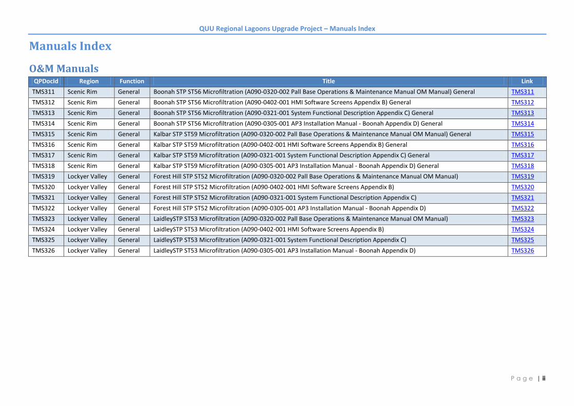
Manuals Index
O&M Manuals QPDocId Region Function Title Link
TMS311 Scenic Rim General Boonah STP ST56 Microfiltration (A090-0320-002 Pall Base Operations & Maintenance Manual OM Manual) General TMS311
TMS312 Scenic Rim General Boonah STP ST56 Microfiltration (A090-0402-001 HMI Software Screens Appendix B) General TMS312
TMS313 Scenic Rim General Boonah STP ST56 Microfiltration (A090-0321-001 System Functional Description Appendix C) General TMS313
TMS314 Scenic Rim General Boonah STP ST56 Microfiltration (A090-0305-001 AP3 Installation Manual - Boonah Appendix D) General TMS314
TMS315 Scenic Rim General Kalbar STP ST59 Microfiltration (A090-0320-002 Pall Base Operations & Maintenance Manual OM Manual) General TMS315
TMS316 Scenic Rim General Kalbar STP ST59 Microfiltration (A090-0402-001 HMI Software Screens Appendix B) General TMS316
TMS317 Scenic Rim General Kalbar STP ST59 Microfiltration (A090-0321-001 System Functional Description Appendix C) General TMS317
TMS318 Scenic Rim General Kalbar STP ST59 Microfiltration (A090-0305-001 AP3 Installation Manual - Boonah Appendix D) General TMS318
TMS319 Lockyer Valley General Forest Hill STP ST52 Microfiltration (A090-0320-002 Pall Base Operations & Maintenance Manual OM Manual) TMS319
TMS320 Lockyer Valley General Forest Hill STP ST52 Microfiltration (A090-0402-001 HMI Software Screens Appendix B) TMS320
TMS321 Lockyer Valley General Forest Hill STP ST52 Microfiltration (A090-0321-001 System Functional Description Appendix C) TMS321
TMS322 Lockyer Valley General Forest Hill STP ST52 Microfiltration (A090-0305-001 AP3 Installation Manual - Boonah Appendix D) TMS322
TMS323 Lockyer Valley General LaidleySTP ST53 Microfiltration (A090-0320-002 Pall Base Operations & Maintenance Manual OM Manual) TMS323
TMS324 Lockyer Valley General LaidleySTP ST53 Microfiltration (A090-0402-001 HMI Software Screens Appendix B) TMS324
TMS325 Lockyer Valley General LaidleySTP ST53 Microfiltration (A090-0321-001 System Functional Description Appendix C) TMS325
TMS326 Lockyer Valley General LaidleySTP ST53 Microfiltration (A090-0305-001 AP3 Installation Manual - Boonah Appendix D) TMS326

QUU Regional Lagoons Upgrade Project – Manuals Index
| iii P a g e
Manuals Index
Vendor Manuals QP Vendor File Description Boonah Kalbar Forest Hill Laidley Link
VM213 ACP A090-070404-001 Compressed Air Pipe Manual x x x x VM213
VM256 Alpha A090-070422-001 FXM650 1100 2000 UPS Installation & Operation Manual x x x x VM256
VM214 Amiad A090-070405-001 Filtomat M100-750 Series Brochure x x x x VM214
VM215 Amiad A090-070405-002 Filtomat M100-750 Series Maintenance Instructions x x x x VM215
VM216 Amiad A090-070405-003 Filomat Inspection Certificate x x x x VM216
VM255 ARI A090-070421-001 D-021 ARV Data Sheet x x x x VM255
VM217 Asahi Kasei A090-070406-001 UNA-620A MF Module Operating Instruction x x x x VM217
VM257 Atlas Copco A090-070423-001 FXE1 Refrigerant Compressed Air Dryers - Instruction Book x x x x VM257
VM258 Atlas Copco A090-070423-002 GX 2-5 FM. Dimension drawing (2202 2609 60 ed. 01) x x x x VM258
VM259 Atlas Copco A090-070423-003 GX2-GX3 Instruction Book x x x x VM259
VM260 Atlas Copco A090-070423-004 PD & DD Filters Instruction Manual x x x x VM260
VM261 Atlas Copco A090-070423-005 Receiver VAR565-1170WP. 9724-5037-52 x x x VM261
VM262 Atlas Copco A090-070423-006 GX2-5 electrical drw x x x x VM262
VM263 Atlas Copco A090-070423-007 Dryer FXe1-3 Service Diagram x x x x VM263
VM264 Atlas Copco A090-070423-008 Dryer Instruction Book FXe1-5 EN x x x x VM264
VM265 Atlas Copco A090-070423-009 Dryer Spare Parts Book FXe1-5 x x x x VM265
VM266 Atlas Copco A090-070423-010 FX1 to 5 Dimension drawing x x x x VM266
VM267 Atlas Copco A090-070423-011 1000 L 10barg VAR STD x x VM267
VM218 Aussie Pumps A090-070407-001 B2KQ-A_EAR4 Data Sheet x x x VM218
VM219 Aussie Pumps A090-070407-002 B3XR-A-ST_EAS1 Data Sheet x x VM219
VM220 Aussie Pumps A090-070407-003 GMP Pump Manual x x x x VM220
VM221 Aussie Pumps A090-070407-004 GMP Pump Operating Instructions x x x x VM221
VM268 Bourke Valves A090-070424-001 Certificate of Conformance x x x x VM268
VM222 Bray Valves A090-070408-001 S20 21 Data Sheet x x x x VM222
VM223 Bray Valves A090-070408-002 S30 31 Data Sheet x x x x VM223
VM224 Bray Valves A090-070408-003 S92-93 Data Sheet x x x x VM224

QUU Regional Lagoons Upgrade Project – Manuals Index
| iv P a g e
QP Vendor File Description Boonah Kalbar Forest Hill Laidley Link
VM225 Bray Valves A090-070408-004 S6A Dimensional Drawing x x x x VM225
VM226 Bray Valves A090-070408-005 S30-S92-S50 Dimensional Drawing x x x x VM226
VM227 Bray Valves A090-070408-006 S31-S92-S50 Dimensional Drawing x x x x VM227
VM228 Bray Valves A090-070408-007 Pneumatic Actuators Product Guide x x x x VM228
VM229 Bray Valves A090-070408-008 RSBV Product Guide x x x x VM229
VM230 BVCI A090-070409-001 2500L Round Squat Corrugated Tank x x x x VM230
VM231 BVCI A090-070409-002 5000L Round Corrugated Tank x VM231
VM232 Caps A090-070410-001 SRV390 Conrader DataSheet x VM232
VM233 Caps A090-070410-002 Equip - Air receiver -GA drawing x VM233
VM328 Cashco A090-070439-001 Cashco - Installation Manual - Pressure Reducing Regulators - Models D & DL
x x x x VM328
VM330 Condamine Electric A090-070441-002 Electrical Safety Compliance Certificate - Boonah x VM330
VM331 Condamine Electric A090-070441-003 Electrical Safety Compliance Certificate - Kalbar x VM331
VM329 Condamine Electrical A090-070441-001 Electrical Safety Compliance Certificate - Forest Hill x VM329
VM332 Condamine Electrical A090-070441-004 Forrest Hill Electrical Certificate x VM332
VM333 Condamine Electrical A090-070441-005 Laidley Electrical Certificate x VM333
VM209 Control IT A090-070401-009 ITP x x x x VM209
VM325 Danfos A090-070436-001 VLT Aqua Drive Operating Instructions x x x x VM325
VM269 Emerson A090-070425-001 Calibration Certificate - Serial 02813759 x VM269
VM270 Emerson A090-070425-002 Calibration Certificate - Serial 02813760 x VM270
VM271 Emerson A090-070425-003 Calibration Certificate - Serial 02832612 x VM271
VM272 Emerson A090-070425-004 Calibration Certificate - Serial 02832616 x VM272
VM273 Emerson A090-070425-005 3900 Manual x x x x VM273
VM234 EzyStrut A090-070411-001 ET3_ET5 Cable Tray Assembly Guide x x x x VM234
VM294 Festo A090-070431-001 Analog Modules x x x x VM294
VM295 Festo A090-070431-002 CPX - Pin Assignment Instructions x x x x VM295
VM296 Festo A090-070431-003 CPX IO and valve blocks - Analogue IO Modules x x x x VM296
VM297 Festo A090-070431-004 CPX IO and valve blocks - Digital IO Modules x x x x VM297
VM298 Festo A090-070431-005 CPX IO and valve blocks - Install & Commisisoning Manual x x x x VM298
VM299 Festo A090-070431-006 CPX IO and valve blocks - Manual x x x x VM299

QUU Regional Lagoons Upgrade Project – Manuals Index
| v P a g e
QP Vendor File Description Boonah Kalbar Forest Hill Laidley Link
VM300 Festo A090-070431-007 CPX Mounting - Data Sheet x x x x VM300
VM301 Festo A090-070431-008 CPX_EN x x x x VM301
VM302 Festo A090-070431-009 CPX-BG-RW-10X Assembly Instructions x x x x VM302
VM303 Festo A090-070431-010 CPX-FB32 IO and valve blocks - Electronics Manual x x x x VM303
VM304 Festo A090-070431-011 CPX-FEC IO and valve blocks - Electronics Manual x x x x VM304
VM305 Festo A090-070431-012 MSB Operating Instructions x x x x VM305
VM306 Festo A090-070431-013 MSF - MS6 Operating Instructions x x x x VM306
VM307 Festo A090-070431-014 MS-LFR Accessories - Data Sheet x x x x VM307
VM308 Festo A090-070431-015 MS-LFR Filter Regulator - Data Sheet x x x x VM308
VM309 Festo A090-070431-016 MS-W Operating Instructions x x x x VM309
VM310 Festo A090-070431-017 SDE1 Pressure Switch - Data Sheet x x x x VM310
VM311 Festo A090-070431-018 SDE1 Pressure Switch - Install Manual x x x x VM311
VM312 Festo A090-070431-019 SDE1 Pressure Switch - Manual x x x x VM312
VM313 Festo A090-070431-020 SDE1-SH Pressure Switch Protective Hood - Data Sheet x x x x VM313
VM314 Festo A090-070431-021 Universal Connecting Cables - Data sheet x x x x VM314
VM315 Festo A090-070431-022 VTSA Valve Terminal - Manual x x x x VM315
VM316 Festo A090-070431-023 QS Series Pneumatic Fittings x x x x VM316
VM317 Festo A090-070431-024 Silencers x x x x VM317
VM274 GMP A090-070426-001 Self Priming End Centrifugal Electric Pumps Installation Instructions
x x x x VM274
VM235 Grundfos A090-070412-001 522 Injection Valve - Operation Manual x x x x VM235
VM236 Grundfos A090-070412-002 DD Chemical Tanks x x x x VM236
VM237 Grundfos A090-070412-003 Foot Valve IOM x x x x VM237
VM238 Gruvlok A090-070413-001 Fig 7305 HDPE Coupling x x x x VM238
VM239 Gruvlok A090-070413-002 Fig 7307 HDPE Transition Coupling x x x x VM239
VM240 Gruvlok A090-070413-003 HDPE Coupling Manual x x x x VM240
VM275 Hach A090-070427-001 Calibration Test Certificate - SC200 Controller - 1206C0043665 x VM275
VM276 Hach A090-070427-002 Calibration Test Certificate - SC200 Controller - 1210C0049992 x VM276
VM277 Hach A090-070427-003 FT660 SC User Manual x x x x VM277
VM278 Hach A090-070427-004 sc200 Controller User Manual x x x x VM278

QUU Regional Lagoons Upgrade Project – Manuals Index
| vi P a g e
QP Vendor File Description Boonah Kalbar Forest Hill Laidley Link
VM279 Hach A090-070427-005 1720E Users Manual x x x x VM279
VM241 Harvel A090-070414-001 Sch. 80 PVC-U Data Sheet x x x x VM241
VM327 Hershey A090-070438-001 Valve - Catalog 2011.05 x x x x VM327
VM242 Jaco A090-070415-001 Compression Fittings Catalogue x x x x VM242
VM212 Johnson Screens A090-070403-001 S 12-69 Intake Screen Drawing x x x x VM212
VM280 Kelco A090-070428-001 F20 Modular Flow Switches Installation & Operating Guide Lines
x x x x VM280
VM243 Lowara A090-070416-001 SHE Pumps Catalogue x x x x VM243
VM244 Lowara A090-070416-002 SHE Pumps Operating Instructions x x x x VM244
VM245 Lowara A090-070416-003 SV-CO-FH-FC-SH-CEF-COF - Safety Instructions x x x x VM245
VM323 Maric A090-070434-001 CFF Brochure x x x x VM323
VM246 Merriman A090-070417-001 Line Strainer 305 x VM246
VM247 Merriman A090-070417-002 Y-strainer x VM247
VM248 Pall A090-070418-001 MF Fiber Information Sheet x x x x VM248
VM322 Pall Beijing A090-070433-001 Quality Documentation x x x x VM322
VM318 Perfab A090-070432-001 Material Data Record - Laidley x VM318
VM319 Perfab A090-070432-002 Material Data Record - Forest Hill x VM319
VM320 Perfab A090-070432-003 Material Data Record - Kalbar x VM320
VM321 Perfab A090-070432-004 Material Data Record - Boonah x VM321
VM281 Rosemount A090-070429-001 644H Temperature Transmitter with 4-20mA Hart Quick Start Guide
x x x x VM281
VM282 Rosemount A090-070429-002 2088, 2090P & 2090F Pressure Transmitter with 4-20 mA Hart Quick Installation Guide
x x x x VM282
VM283 Rosemount A090-070429-003 8700 Series Magnetic Flowmeter Sensors - Quick Intallation Guide
x x x x VM283
VM284 Rosemount A090-070429-004 8732e Magnetic Flowmeter System - Quick Installaiton Guide x x x x VM284
VM285 Rosemount A090-070429-005 Declaration of Conformity x x x x VM285
VM286 Rosemount A090-070429-006 Magnetic 8732 Flowmeter Factory Configuration - Serial No 0354479
x x x x VM286
VM287 Rosemount A090-070429-007 Magnetic 8732 Flowmeter Factory Configuration - Serial No 0354480
x x x x VM287
VM288 Rosemount A090-070429-008 148TemperatureTransmitter_RevAA x x x x VM288

QUU Regional Lagoons Upgrade Project – Manuals Index
| vii P a g e
QP Vendor File Description Boonah Kalbar Forest Hill Laidley Link
VM289 Rosemount A090-070429-009 644HeadandRailMountTemperatureTransmitters_RevJA x x x x VM289
VM290 Rosemount A090-070429-010 RTD&ThermcoupleAssemblies_RevBA x x x VM290
VM324 Solberg A090-070435-001 F Series Filters x x x x VM324
VM249 Spears A090-070419-001 Saddle x x x x VM249
VM250 Spears A090-070419-002 Sch.80 Fittings x x x x VM250
VM251 Spears A090-070419-003 True Union Valves x x x x VM251
VM252 Spears A090-070419-004 Y-strainer x x x x VM252
VM326 Spill Station Australia A090-070437-001 Bunding Information x x x x VM326
VM210 TEE A090-070402-001 CIP Tank Heater - General Arrangement - TIH1001500 x x VM210
VM211 TEE A090-070402-002 CIP Tank Heater - General Arrangement - TIH1001200 x x x VM211
VM291 Vega A090-070430-001 PLICCOM Operating instructions x x x x VM291
VM292 Vega A090-070430-002 Vegason 61 Operating Instructions x x x x VM292
VM293 Vega A090-070430-003 Vegason 61 Product Info x x x x VM293
VM253 Wilden A090-070420-001 P25 Manual x x x x VM253
VM254 Wilden A090-070420-002 Declaration of Conformity x x x x VM254
VM334 Control IT A0901-070401-001 Checklist MCP - Boonah x VM334
VM335 Control IT A0901-070401-005 Commissioning MCP - Boonah x VM335
VM336 Control IT A0901-070401-010 Compliance Certificate - Boonah x VM336
VM337 Control IT A0902-070401-002 Checklist MCP - Kalbar x VM337
VM338 Control IT A0902-070401-006 Commissioning MCP - Kalbar x VM338
VM339 Control IT A0902-070401-011 Compliance Certificate - Kalbar x VM339
VM340 Control IT A0903-070401-003 Checklist - MCP - Laidley x VM340
VM341 Control IT A0903-070401-007 Commissioning MCP - Laidley x VM341
VM342 Control IT A0903-070401-012 Compliance Certifiate - Laidley x VM342
VM343 Control IT A0903-070401-013 Cabinet & Panel Checklist - MCP - Laidley x VM343
VM344 Control IT A0903-070401-014 Commissioning Checklist - MCP - Laidley x VM344
VM345 Control IT A0904-070401-004 Checklist MCP - Forest Hill x VM345
VM346 Control IT A0904-070401-008 Commissioning MCP - Forest Hill x VM346
VM347 Control IT A0904-070401-015 Compliance Certificate - Forest Hill x VM347

Quick Start Guide
00825-0200-4728, Rev AC
November 2012
Note:Before installing the transmitter, confirm the correct Device Driver is loaded on the host
systems. See page 3 for System Readiness.
Rosemount 644H Temperature Transmitter
with 4-20 mA HART (Revision 5 and 7) Protocol
Vendor Manual Rosemount A090-070429-001 644H Temperature Transmitter with 4-20mA Hart Quick Start Guide
Q-Pulse Id VM281 Active 09/09/2013 Page 1 of 30
LeeR
Text Box
A090-070429-001

November 2012
2
Quick Start Guide� � � � � �This installation guide provides basic guidelines for Rosemount 644 transmitters. It does not
provide instructions for configuration, diagnostics, maintenance, service, troubleshooting,
Explosion-proof, Flameproof, or intrinsically safe (I.S.) installations. Refer to the Rosemount 644 reference manual (document number 00809-0100-4728) for more instruction.
This manual is also available electronically on www.rosemount.com.
Explosions could result in death or serious injury:
Installation of this transmitter in an explosive environment must be in accordance with the
appropriate local, national, and international standards, codes, and practices. Please review the approvals section of the 644 reference manual for any restrictions associated with a safe
installation.
Before connecting a HART-based communicator in an explosive atmosphere, make sure the
instruments in the loop are installed in accordance with intrinsically safe or non-incendive
field wiring practices.
Electrical shock can result in death or serious injury.
Avoid contact with the leads and the terminals. High voltage that may be present on leads
can cause electrical shock.
Conduit/Cable Entries
Unless marked, the conduit/cable entries in the transmitter housing use a 1/2-14 NPT thread
form. Entries marked "M20" are M20 x 1.5 thread form. On devices with multiple conduit
entries, all entries will have the same thread form. Only use plugs, adapters, glands, or
conduit with a compatible thread form when closing these entries.
ContentsSystem readiness . . . . . . . . . . . . . . . . . . . . . . . . . 3
Confirm HART revision capability . . . . . . . . . 3
Confirm correct device driver . . . . . . . . . . . . 3
Transmitter installation . . . . . . . . . . . . . . . . . . . . 4
Step 1: Set the alarm switch. . . . . . . . . . . . . . 4
Step 2: Verify configuration . . . . . . . . . . . . . . 4
Step 3: Mount the transmitter . . . . . . . . . . . 10
Step 4: Wire And Apply Power . . . . . . . . . . . 12
Step 5: Perform a loop test. . . . . . . . . . . . . . 16
Safety Instrumented Systems . . . . . . . . . . . . . 17
Product Certifications . . . . . . . . . . . . . . . . . . . . 18
Vendor Manual Rosemount A090-070429-001 644H Temperature Transmitter with 4-20mA Hart Quick Start Guide
Q-Pulse Id VM281 Active 09/09/2013 Page 2 of 30

Quick Start Guide
3
November 2012
System readiness
Confirm HART revision capabilityIf using HART based control or asset management systems, please confirm the HART capability of those systems prior to transmitter installation. Not all systems are capable of communicating with HART Revision 7 protocol. This transmitter can be configured for either HART Revision 5 or 7.For instructions on how to change the HART revision of your transmitter, see Step 2: Verify configuration on page 4.
Confirm correct device driverVerify the latest Device Driver files are loaded on your systems to ensure proper communications.Download the latest Device Driver at www.emersonprocess.com.en-US/documentation/deviceinstallkits/Pages/AboutDeviceInstallKits.aspx or http://www.hartcomm.org/protocol/products/products.html
Rosemount 644 device revisions and files
Table 1 provides the information necessary to ensure you have the correct Device Driver files and Documentation for your device.
Table 1. Rosemount 644 Device Revisions and Files
Software Date
Identify DeviceFind Device Driver
FilesReview
InstructionsReview
Functionality
DateNAMUR
Software Revision
HART Software Revision
HART Universal Revision1
1. NAMUR Software Revision is located on the hardware tag of the device. HART Software Revision can be read using a HART communication tool.
Device Revision2
2. Device Driver file names use Device and DD Revision, e.g. 10_01. HART Protocol is designed to enable legacydevice driver revisions to continue to communicate with new HART devices. To access new functionality, the new Device Driver must be downloaded. It is recommended to download new Device Driv-er files to ensure full functionality.
Manual Document
Number
Changes to Software3
3. HART Revision 5 and 7 Selectable, Dual Sensor support, Safety Certified, Advanced Diagnostics (if ordered),Enhanced Accuracy and Stability (if ordered).
June 2012 1.1.1 01
5 8
00809-0100-4728See footnote 3 for list of changes.
7 9
1. NAMUR Software Revision is located on the hardware tag of the device. HART Software Revision can be read using a HART communication tool.
Vendor Manual Rosemount A090-070429-001 644H Temperature Transmitter with 4-20mA Hart Quick Start Guide
Q-Pulse Id VM281 Active 09/09/2013 Page 3 of 30

November 2012
4
Quick Start Guide
Transmitter installation
Step 1: Set the alarm switch
Set the 644 Alarm Switch before putting the device into operation.
Without a LCD Display
1. Set the loop to manual (if applicable) and disconnect the power.
2. Remove the housing cover.
3. Set the switch to the desired position. H indicates High, L indicates Low. Then reattach the housing cover.
4. Apply power and set the loop to automatic control.
Figure 1. Placement of Alarm Switch
NoteIf using an LCD Display, first remove the display by detaching it from the top of the device, set the
switch to the desired position and reattach the LCD Display.
Step 2: Verify configuration
Verify the configuration of the Rosemount 644 device upon receiving your transmitter using any HART compliant configuration tool. See the Rosemount 644 Reference Manual (00809-0200-4728) for configuration instructions using AMS Device Manager.
The 644 communicates using the Field Communicator (communication requires a loop resistance between 250 and 1100 ohms). Do not operate when power is below 12 Vdc at the transmitter terminal. Refer to the 644 Reference Manual (document number 00809-0200-4728) and the Field Communicator Reference Manual for more information.
Vendor Manual Rosemount A090-070429-001 644H Temperature Transmitter with 4-20mA Hart Quick Start Guide
Q-Pulse Id VM281 Active 09/09/2013 Page 4 of 30
Quick Start Guide
5
November 2012
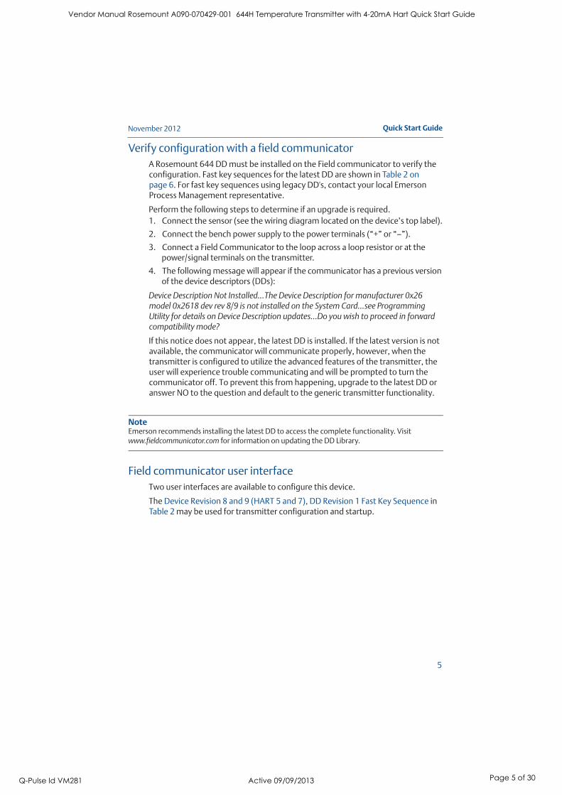
Verify configuration with a field communicator
A Rosemount 644 DD must be installed on the Field communicator to verify the configuration. Fast key sequences for the latest DD are shown in Table 2 on page 6. For fast key sequences using legacy DD's, contact your local Emerson Process Management representative.
Perform the following steps to determine if an upgrade is required.
1. Connect the sensor (see the wiring diagram located on the device’s top label).
2. Connect the bench power supply to the power terminals (“+” or “–”).
3. Connect a Field Communicator to the loop across a loop resistor or at the power/signal terminals on the transmitter.
4. The following message will appear if the communicator has a previous version of the device descriptors (DDs):
Device Description Not Installed…The Device Description for manufacturer 0x26 model 0x2618 dev rev 8/9 is not installed on the System Card…see Programming Utility for details on Device Description updates…Do you wish to proceed in forward compatibility mode?
If this notice does not appear, the latest DD is installed. If the latest version is not available, the communicator will communicate properly, however, when the transmitter is configured to utilize the advanced features of the transmitter, the user will experience trouble communicating and will be prompted to turn the communicator off. To prevent this from happening, upgrade to the latest DD or answer NO to the question and default to the generic transmitter functionality.
NoteEmerson recommends installing the latest DD to access the complete functionality. Visit
www.fieldcommunicator.com for information on updating the DD Library.
Field communicator user interface
Two user interfaces are available to configure this device.
The Device Revision 8 and 9 (HART 5 and 7), DD Revision 1 Fast Key Sequence in Table 2 may be used for transmitter configuration and startup.
Vendor Manual Rosemount A090-070429-001 644H Temperature Transmitter with 4-20mA Hart Quick Start Guide
Q-Pulse Id VM281 Active 09/09/2013 Page 5 of 30

November 2012
6
Quick Start Guide
Figure 2. Device Dashboard Field Communicator Interface
Table 2. Device Revision 8 and 9 (HART 5 and 7), DD Revision 1 Fast Key Sequence
Function HART 5 HART 7
Alarm Values 2, 2, 5, 6 2, 2, 5, 6
Analog Calibration 3, 4, 5 3, 4, 5
Analog Output 2, 2, 5, 1 2, 2, 5, 1
Average Temperature Setup 2, 2, 3, 3 2, 2, 3, 3
Burst Mode 2, 2, 8, 4 2, 2, 8, 4
Comm Status1, 2
Configure additional messages2, 2, 8, 4, 7
Configure Hot Backup 2, 2, 4, 1, 32, 2, 4, 1, 3
D/A Trim 3, 4, 4, 1 3, 4, 4, 1
Damping Values 2, 2, 1, 5 2, 2, 1, 6
Date2, 2, 7, 1, 2 2, 2, 7, 1, 3
Display Setup2, 1, 4 2, 1, 4
Descriptor 2, 2, 7, 1, 4 2, 2, 7, 1, 5
Device Information 1, 8, 1 1, 8, 1
Differential Temperature Setup 2, 2, 3, 1 2, 2, 3, 1
Drift Alert 2, 2, 4, 2 2, 2, 4, 2
Vendor Manual Rosemount A090-070429-001 644H Temperature Transmitter with 4-20mA Hart Quick Start Guide
Q-Pulse Id VM281 Active 09/09/2013 Page 6 of 30

Quick Start Guide
7
November 2012
Filter 50/60 Hz 2, 2, 7, 4, 1 2, 2, 7, 4, 1
First Good Temperature Setup 2, 2, 3, 2 2, 2, 3, 2
Hardware Revision 1, 8, 2, 3 1, 8, 2, 3
HART Lock 2, 2, 9, 2
Intermittent Sensor Detect 2, 2, 7, 4, 2 2, 2, 7, 4, 2
Loop Test 3, 5, 1 3, 5, 1
Locate Device 3, 4, 6, 2
Lock Status 1, 8, 3, 8
LRV (Lower Range Value) 2, 2, 5, 5, 3 2, 2, 5, 5, 3
LSL (Lower Sensor Limit) 2, 2, 1, 7, 2 2, 2, 1, 8, 2
Message 2, 2, 7, 1, 3 2, 2, 7, 1, 4
Open Sensor Holdoff 2, 2, 7, 3 2, 2, 7, 3
Percent Range 2, 2, 5, 2 2, 2, 5, 2
Sensor 1 Configuration 2, 1, 1 2, 1, 1
Sensor 2 Configuration 2, 1, 1 2, 1, 1
Sensor 1 Serial Number 2, 2, 1, 6 2, 2, 1, 7
Sensor 2 Serial Number 2, 2, 2, 7 2, 2, 2, 8
Sensor 1 Type 2, 2, 1, 2 2, 2, 1, 3
Sensor 2 Type 2, 2, 2, 2 2, 2, 2, 3
Sensor 1 Unit 2, 2, 1, 4 2, 2, 1, 5
Sensor 2 Unit 2, 2, 2, 4 2, 2, 2, 5
Sensor 1 Status 2, 2, 1, 2
Sensor 2 Status 2, 2, 2, 2
Simulate Digital Signal 3, 5, 2
Software Revision 1, 8, 2, 4 1, 8, 2, 4
Tag 2, 2, 7, 1, 1 2, 2, 7, 1, 1
Long Tag 2, 2, 7, 1, 2
Terminal Temperature 2, 2, 7, 1 2, 2, 8, 1
URV (Upper Range Value) 2, 2, 5, 5, 2 2, 2, 5, 5, 2
USL (Upper Sensor Limit) 2, 2, 1, 7, 2 2, 2, 1, 8, 2
Variable Mapping 2, 2, 8, 5 2, 2, 8, 5
2-wire Offset Sensor 1 2, 2, 1, 9 2, 2, 1, 10
2-wire Offset Sensor 2 2, 2, 2, 9 2, 2, 2, 10
Function HART 5 HART 7
Vendor Manual Rosemount A090-070429-001 644H Temperature Transmitter with 4-20mA Hart Quick Start Guide
Q-Pulse Id VM281 Active 09/09/2013 Page 7 of 30

November 2012
8
Quick Start Guide
Input or verify Callendar Van-Dusen constants
If sensor matching is being used with this combination of a transmitter and sensor, verify the constants input.
1. From the HOME screen, select 2 Configure, 2 Manual Setup, 1 Sensor. Set the control loop to manual and select OK.
2. Select Cal VanDusen at the ENTER SENSOR TYPE prompt.
3. Select the appropriate number of wires at the ENTER SENSOR CONNECTION prompt.
4. Enter the Ro, Alpha, Delta, and Beta values from the stainless steel tag attached to the special-order sensor when prompted.
5. Return the control loop to automatic control and select OK.
6. To disable the transmitter-sensor matching feature from the HOME screen select 2 Configure, 2 Manual Setup, 1 Sensor, 10 SensorMatching-CVD. Choose the appropriate sensor type from the ENTER SENSOR TYPE prompt.
Verifying configuration with Local Operator Interface (LOI)
The optional LOI can be used for commissioning the device. The LOI is a two button design. To activate the LOI push any button. LOI button functionality is shown on the bottom corners of the display. See Table 3 and Figure 4 for button operation and menu information.
Figure 3. Local Operator Interface
Table 3. LOI Button Operation
Vendor Manual Rosemount A090-070429-001 644H Temperature Transmitter with 4-20mA Hart Quick Start Guide
Q-Pulse Id VM281 Active 09/09/2013 Page 8 of 30
Quick Start Guide
9
November 2012
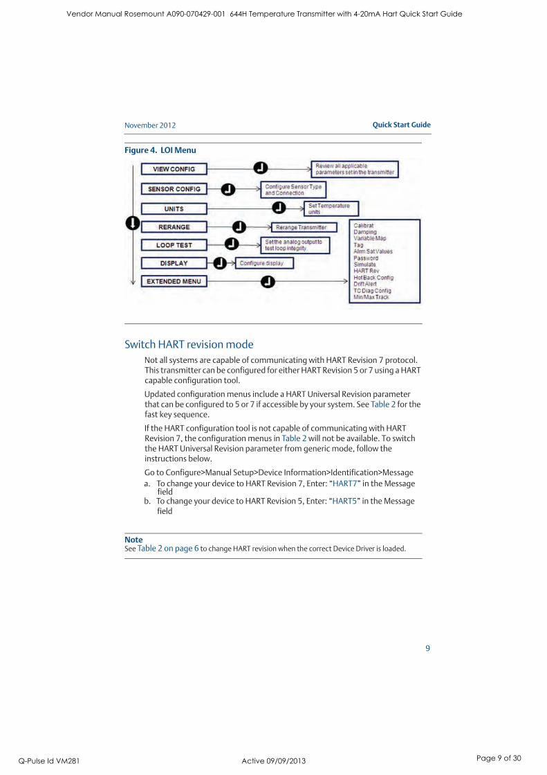
Figure 4. LOI Menu
Switch HART revision mode
Not all systems are capable of communicating with HART Revision 7 protocol. This transmitter can be configured for either HART Revision 5 or 7 using a HART capable configuration tool.
Updated configuration menus include a HART Universal Revision parameter that can be configured to 5 or 7 if accessible by your system. See Table 2 for the fast key sequence.
If the HART configuration tool is not capable of communicating with HART Revision 7, the configuration menus in Table 2 will not be available. To switch the HART Universal Revision parameter from generic mode, follow the instructions below.
Go to Configure>Manual Setup>Device Information>Identification>Message
a. To change your device to HART Revision 7, Enter: “HART7” in the Message field
b. To change your device to HART Revision 5, Enter: “HART5” in the Message field
NoteSee Table 2 on page 6 to change HART revision when the correct Device Driver is loaded.
Vendor Manual Rosemount A090-070429-001 644H Temperature Transmitter with 4-20mA Hart Quick Start Guide
Q-Pulse Id VM281 Active 09/09/2013 Page 9 of 30

November 2012
10
Quick Start Guide
Step 3: Mount the transmitter
Mount the transmitter at a high point in the conduit run to prevent moisture from draining into the transmitter housing.
Typical connection head installation
Head mount transmitter with DIN plate style sensor1. Attach the thermowell to the pipe or process container wall. Install and
tighten the thermowell before applying process pressure.
2. Verify the transmitter failure mode switch position.
3. Assemble the transmitter to the sensor. Push the transmitter mounting screws through the sensor mounting plate.
4. Wire the sensor to the transmitter (see Step 4: Wire And Apply Power).
5. Insert the transmitter-sensor assembly into the connection head. Thread the transmitter mounting screw into the connection head mounting holes. Assemble the extension to the connection head. Insert the assembly into the thermowell.
6. If using a cable gland, properly attach the cable gland to a housing conduit entry.
7. Insert the shielded cable leads into the connection head through the cable entry.
8. Connect the shielded power cable leads to the transmitter power terminals. Avoid contact with sensor leads and sensor connections. Connect and tighten the cable gland.
9. Install and tighten the connection head cover. Enclosure covers must be fully engaged to meet explosion-proof requirements.
A = Connection Head Cover D = Transmitter Mounting Screws
B = Connection Head E = Integral Mount Sensor with Flying Leads
C = Thermowell F = Extension
ABLE
3/4SCALE � �� �
Vendor Manual Rosemount A090-070429-001 644H Temperature Transmitter with 4-20mA Hart Quick Start Guide
Q-Pulse Id VM281 Active 09/09/2013 Page 10 of 30

Quick Start Guide
11
November 2012
Typical universal head installation
Head mount transmitter with threaded sensor1. Attach the thermowell to the pipe or process container wall. Install and
tighten thermowells before applying process pressure.
2. Attach necessary extension nipples and adapters to the thermowell. Seal the nipple and adapter threads with silicone tape.
3. Screw the sensor into the thermowell. Install drain seals if required for severe environments or to satisfy code requirements.
4. Verify the transmitter failure mode switch is in the desired position.
5. Pull the sensor wiring leads through the universal head and transmitter center hole. Mount the transmitter in the universal head by threading the transmitter mounting screws into the universal head mounting holes.
6. Mount the transmitter-sensor assembly into the thermowell, or remote mount if desired. Seal adapter threads with silicone tape.
7. Pull the field wiring leads through the conduit into the universal head. Attach the sensor and power leads to the transmitter. Avoid contact with other terminals.
8. Install and tighten the universal head cover. Enclosure covers must be fully engaged to meet explosion-proof requirements.
A = Threaded Thermowell D = Universal Head (transmitter inside)
B = Threaded Style Sensor E = Conduit Entry
C = Standard Extension
3/4SCALE
� � ��
Vendor Manual Rosemount A090-070429-001 644H Temperature Transmitter with 4-20mA Hart Quick Start Guide
Q-Pulse Id VM281 Active 09/09/2013 Page 11 of 30

November 2012
12
Quick Start Guide
Step 4: Wire And Apply Power
Wire the sensor to the TransmitterThe Wiring diagram is located on the device’s top label below the terminal screws
Figure 5. 644 Single and Dual Input Wiring Diagrams
*The transmitter must be configured for at least a 3-wire RTD in order to recognize an RTD with a compensation loop.
** Rosemount Inc. provides a 4-wire sensors for all single element RTDs. Use these RTDs in 3-wire configurations by leaving the unneeded leads disconnected and insulated with electrical tape.
Vendor Manual Rosemount A090-070429-001 644H Temperature Transmitter with 4-20mA Hart Quick Start Guide
Q-Pulse Id VM281 Active 09/09/2013 Page 12 of 30
Quick Start Guide
13
November 2012
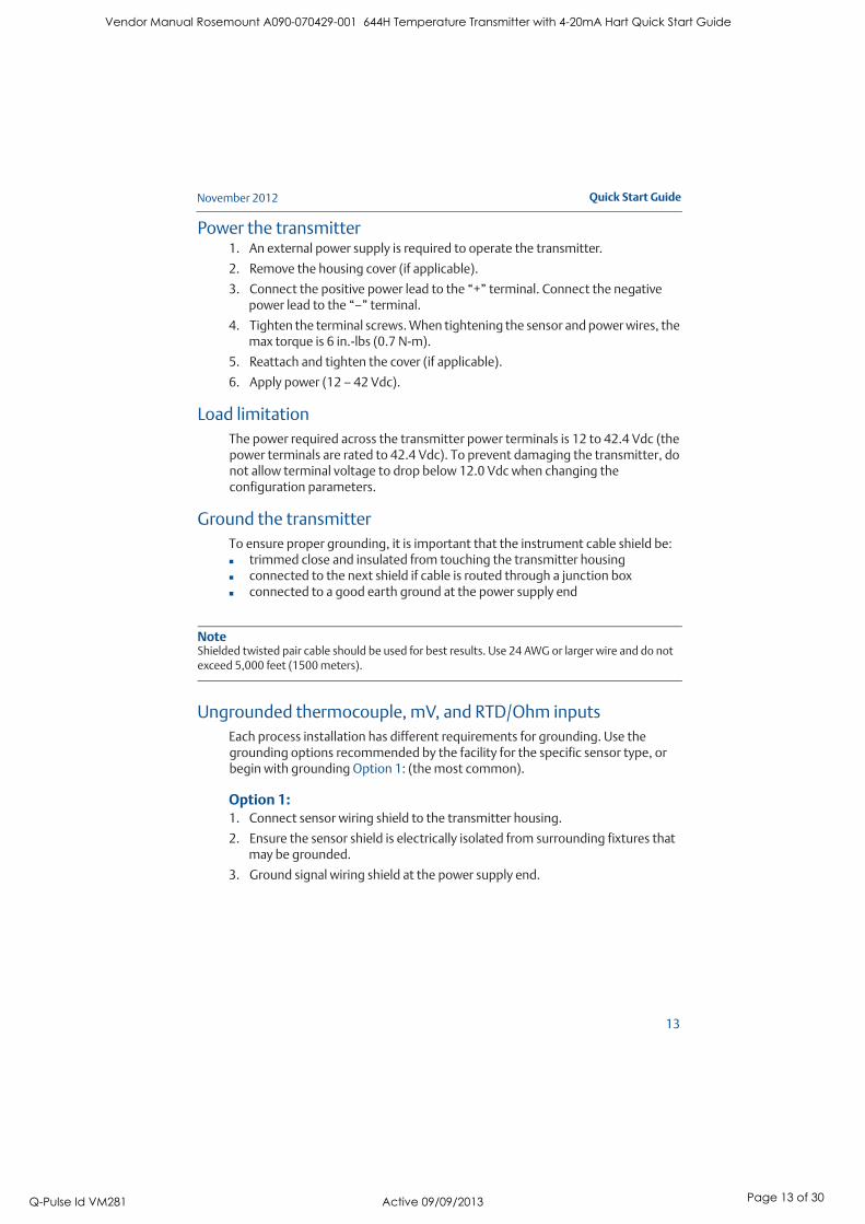
Power the transmitter1. An external power supply is required to operate the transmitter.
2. Remove the housing cover (if applicable).
3. Connect the positive power lead to the “+” terminal. Connect the negative power lead to the “–” terminal.
4. Tighten the terminal screws. When tightening the sensor and power wires, the max torque is 6 in.-lbs (0.7 N-m).
5. Reattach and tighten the cover (if applicable).
6. Apply power (12 – 42 Vdc).
Load limitation
The power required across the transmitter power terminals is 12 to 42.4 Vdc (the power terminals are rated to 42.4 Vdc). To prevent damaging the transmitter, do not allow terminal voltage to drop below 12.0 Vdc when changing the configuration parameters.
Ground the transmitter
To ensure proper grounding, it is important that the instrument cable shield be:trimmed close and insulated from touching the transmitter housingconnected to the next shield if cable is routed through a junction boxconnected to a good earth ground at the power supply end
NoteShielded twisted pair cable should be used for best results. Use 24 AWG or larger wire and do not
exceed 5,000 feet (1500 meters).
Ungrounded thermocouple, mV, and RTD/Ohm inputs
Each process installation has different requirements for grounding. Use the grounding options recommended by the facility for the specific sensor type, or begin with grounding Option 1: (the most common).
Option 1:1. Connect sensor wiring shield to the transmitter housing.
2. Ensure the sensor shield is electrically isolated from surrounding fixtures that may be grounded.
3. Ground signal wiring shield at the power supply end.
Vendor Manual Rosemount A090-070429-001 644H Temperature Transmitter with 4-20mA Hart Quick Start Guide
Q-Pulse Id VM281 Active 09/09/2013 Page 13 of 30
November 2012
14
Quick Start Guide
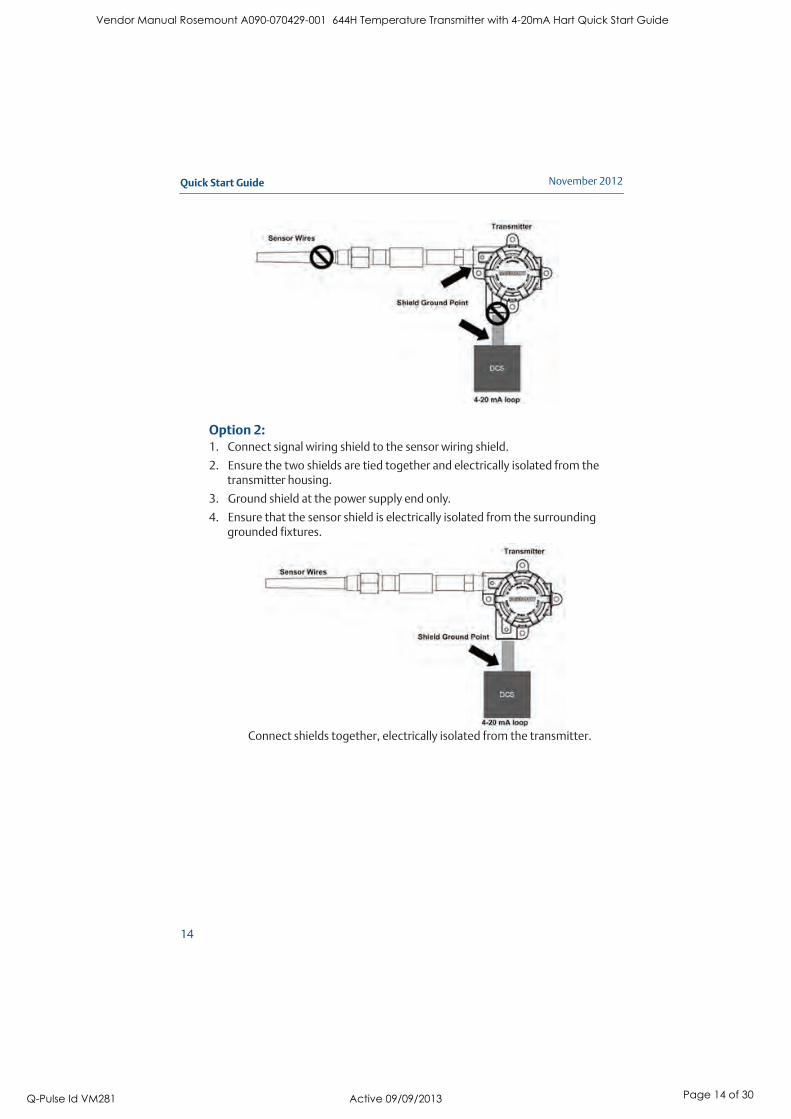
Option 2:1. Connect signal wiring shield to the sensor wiring shield.
2. Ensure the two shields are tied together and electrically isolated from the transmitter housing.
3. Ground shield at the power supply end only.
4. Ensure that the sensor shield is electrically isolated from the surrounding grounded fixtures.
Connect shields together, electrically isolated from the transmitter.
Vendor Manual Rosemount A090-070429-001 644H Temperature Transmitter with 4-20mA Hart Quick Start Guide
Q-Pulse Id VM281 Active 09/09/2013 Page 14 of 30

Quick Start Guide
15
November 2012
Option 3:1. Ground sensor wiring shield at the sensor, if possible.
2. Insure that the sensor wiring and signal wiring shields are electrically isolated from the transmitter housing.
3. Do not connect the signal wiring shield to the sensor wiring shield.
4. Ground signal wiring shield at the power supply end.
Grounded thermocouple inputs
Option 1:1. Ground sensor wiring shield at the sensor.
2. Ensure that the sensor wiring and signal wiring shields are electrically isolated from the transmitter housing.
3. Do not connect the signal wiring shield to the sensor wiring shield.
4. Ground signal wiring shield at the power supply end.
Vendor Manual Rosemount A090-070429-001 644H Temperature Transmitter with 4-20mA Hart Quick Start Guide
Q-Pulse Id VM281 Active 09/09/2013 Page 15 of 30
November 2012
16
Quick Start Guide
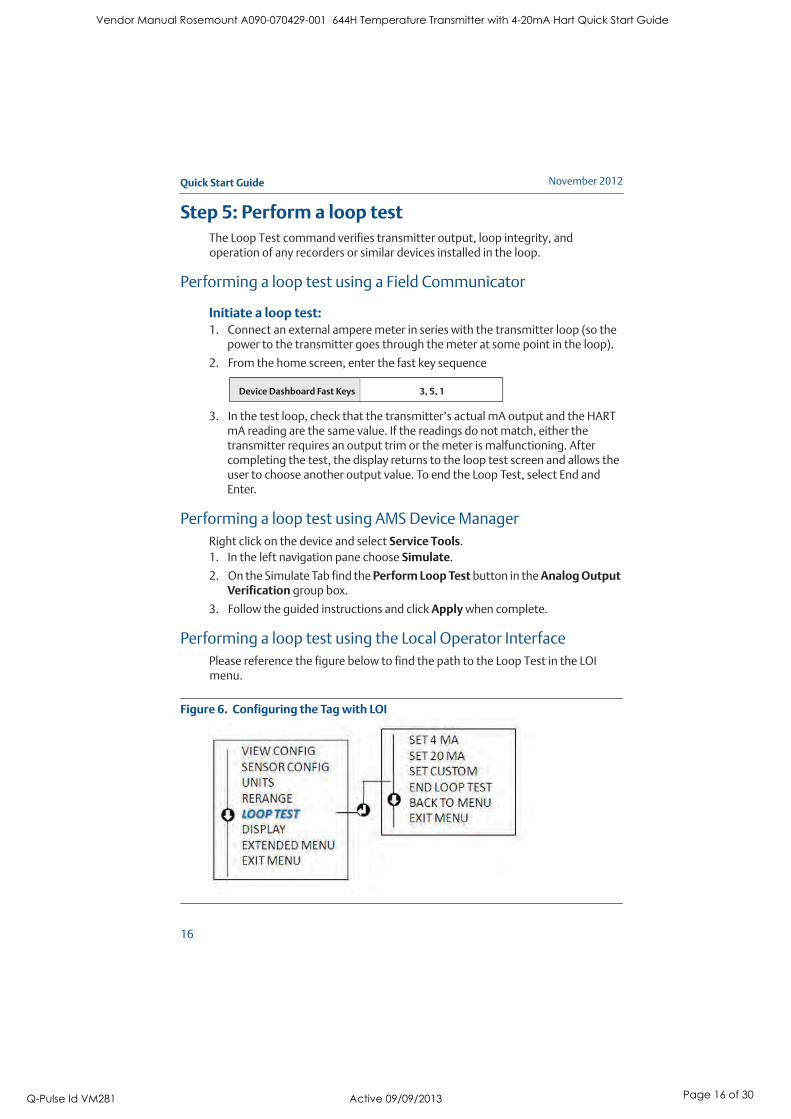
Step 5: Perform a loop test
The Loop Test command verifies transmitter output, loop integrity, and operation of any recorders or similar devices installed in the loop.
Performing a loop test using a Field Communicator
Initiate a loop test:1. Connect an external ampere meter in series with the transmitter loop (so the
power to the transmitter goes through the meter at some point in the loop).
2. From the home screen, enter the fast key sequence
3. In the test loop, check that the transmitter’s actual mA output and the HART mA reading are the same value. If the readings do not match, either the transmitter requires an output trim or the meter is malfunctioning. After completing the test, the display returns to the loop test screen and allows the user to choose another output value. To end the Loop Test, select End and Enter.
Performing a loop test using AMS Device Manager
Right click on the device and select Service Tools.
1. In the left navigation pane choose Simulate.
2. On the Simulate Tab find the Perform Loop Test button in the Analog Output Verification group box.
3. Follow the guided instructions and click Apply when complete.
Performing a loop test using the Local Operator Interface
Please reference the figure below to find the path to the Loop Test in the LOI menu.
Figure 6. Configuring the Tag with LOI
Device Dashboard Fast Keys 3, 5, 1
Vendor Manual Rosemount A090-070429-001 644H Temperature Transmitter with 4-20mA Hart Quick Start Guide
Q-Pulse Id VM281 Active 09/09/2013 Page 16 of 30

Quick Start Guide
17
November 2012
Safety Instrumented Systems
For Safety Certified installations, please refer to the Rosemount 644 reference manual (document number 00809-0200-4728). The manual is available electronically on www.rosemount.com or by contacting an Emerson Process Management representative.
Vendor Manual Rosemount A090-070429-001 644H Temperature Transmitter with 4-20mA Hart Quick Start Guide
Q-Pulse Id VM281 Active 09/09/2013 Page 17 of 30

November 2012
18
Quick Start Guide
Product Certifications
European Union Directive Information
The EC declaration of conformity for all applicable European directives for this product can be found on page 24. The latest revision of the Declaration is available at www.emersonprocess.com.
Ordinary Location Certification from FM Approvals
As standard, the transmitter has been examined and tested to determine that the design meets basic electrical, mechanical, and fire protection requirements by FM Approvals, a nationally recognized testing laboratory (NRTL) as accredited by the Federal Occupational Safety and Health Administration (OSHA).
Hazardous Locations Certifications
North American Certifications
FM Approvals
I5 Intrinsically Safe and Non-IncendiveCertificate No: 3044581
Applicable Standards: FM Class 3600 – 1998, FM Class 3610 – 2010, FM Class 3611 –
2004, FM Class 3810 – 2005, ANSI/NEMA 250 - 2003
Markings (without enclosure):
INT. SAFE CL I, GP ABCD, T4
IS CL I Zone 0, AEX ia IIC; T4 GaNI CL I, DIV.2, GP ABCD
INSTALL PER DRAWINGS 00644-2071
Markings (with enclosure):
IS CL I,II,III, GP ABCDEFG T4IS CL I Zone 0, AEX ia IIC; T4
NI CL I, DIV.2, GP ABCD
INSTALL PER DRAWINGS 00644-2071ENCLOSURE TYPE 4X
Special Conditions for Safe Use (X)
The surface resistivity of the non-metallic enclosure materials is greater than one gigaohm. Care must be taken to avoid electrostatic charge build-up. Do not rub or cleaned with solvents or a dry cloth.The Model 644 optional enclosures may contain aluminum and are considered a potential risk of ignition by impact or friction. Care must be taken into account during installation and use to prevent impact and friction.
E5 Explosion-Proof and Dust Ignition Proof
Certificate No: 3006278Applicable Standards: FM Class 3600 – 1998, FM Class 3615 – 2006, FM Class 3810 –
2005, ANSI/NEMA 250 - 2003
Vendor Manual Rosemount A090-070429-001 644H Temperature Transmitter with 4-20mA Hart Quick Start Guide
Q-Pulse Id VM281 Active 09/09/2013 Page 18 of 30

Quick Start Guide
19
November 2012
Markings:EXPLOSIONPROOF FOR CL. I, DIV. 1, GP BCD
DUST-IGNITIONPROOF FOR CL. II & III, DIV. 1, GP EFGNON-INCENDIVE FOR CL. I, DIV 2, GP ABCD
WHEN INSTALLED PER ROSEMOUNT DRAWING 00644-1049
CONDUIT SEAL REQUIRED WITHIN 18 INCHES OF THE ENCLOSURE AT AMBIENT TEMPERATURES BELOW -40 °C;
ENCLOSURE TYPE 4X
CSA International
I6 Intrinsically Safe
Certificate No.: 1091070Applicable Standards: CSA Std. C22.2 No. 142 – M1987, CSA Std. C22.2 No. 157 – 92,
ANSI/ISA 12.27.02-2003
Markings (without enclosure):
Ex iaCLASS I (GRPS A, B, C, D) CLASS I, ZONE 0, IIC
SUITABLE FOR CLASS I DIV 2, GROUPS A, B, C, D
INSTALL PER DRAWING 00644-2072.
Markings (with enclosure):
Ex ia CLASS I, GRPS A,B,C,D, T4/T6, CLASS I, ZONE 0, IIC
WHEN INSTALL PER DRAWING 00644-1064 or 0644-2072
SUITABLE CLASS I DIV 2, WITH NON-INCENDIVE OUTPUT WHEN INSTALL PER DRAWING 00644-2072
ENCLOSURE TYPE 4X
K6 Explosion-Proof, Dust Ignition Proof, Intrinsically Safe and Suitable for Class I Division
2Certificate No.: 1091070
Applicable Standards: CSA Std. C22.2 No. 142 – M1987, CSA Std. C22.2 No. 30 –
M1986, CSA Std. C22.2 No. 213 – M1987, ANSI/ISA 12.27.02-2003
Markings:CL I, DIV. 1, GRPS. B,C,D; DUST-IGNITION PROOF, CL II, GRPS E,F, CL. III;
SUITABLE FOR CL I, DIV. 2, GROUPS A,B,C,D
INSTALL PER DRAWING 00644-1059ENCLOSURE TYPE 4X; CONDUIT SEAL NOT REQUIRED,
---------------------------------------------------------------------------------------------------------------------
Ex ia
INTRINSICALLY SAFE, CLASS I, GROUPS A, B, C, D, T4/T5/T6CLASS I, ZONE 0, IIC.
INSTALL PER DRAWING 00644-1064 or 00644-2072.SUITABLE FOR CLASS I DIV 2, GROUPS A, B, C, D
INSTALL PER DRAWING 00644-2072.
European Certifications
I1 ATEX Intrinsic Safety Certificate No.: Baseefa 12ATEX0101X
Applicable Standards: IEC 60079-0: 2011, EN60079-11: 2007
Markings: II 1 G, Ex ia IIC T6…T4 Ga; See Certificate (Table 4)
1180
Vendor Manual Rosemount A090-070429-001 644H Temperature Transmitter with 4-20mA Hart Quick Start Guide
Q-Pulse Id VM281 Active 09/09/2013 Page 19 of 30

November 2012
20
Quick Start Guide
Special Conditions for Safe Use (X)
The apparatus must be installed in an enclosure which affords a degree of protection of at least IP20.
Non-metallic enclosures must have a surface resistance of less than 1Gohm.Light alloy or zirconium enclosures must be protected from impact and friction when installed.
Table 4. Input Parameters
N1 ATEX Type n (with enclosure)
Certification No.: BAS 00ATEX3145 Applicable Standards: EN 60079-0: 2006, EN60079-15: 2005
Markings: II 3 G, Ex nA IIC T5 Gc (-40 °C Ta 70 °C)
Specific Conditions for Safe Use (X):
1. The apparatus is not capable of withstanding the 500 V insulation test required by Clause 6.8.1 of EN 60079-15:2005. This must be taken into account when installing the apparatus.
NC ATEX Type n (without enclosure)Certificate No.: Baseefa12ATEX0102U
Applicable Standards: IEC 60079-0: 2011, EN60079-15: 2005
Markings: II 3 G, Ex nA IIC T6…T5 Gc Vmax = 45 volts max
Temperature limitations – T6 (-60 °C Ta 40 °C), T5 (-60 °C Ta 85 °C)
Special Conditions for safe use (x):
The component must be installed in a suitably certified enclosure such that it is afforded a degree of protection of at least IP54 in accordance with IEC 60529, IEC 60079-0 & EN 60079-15.
Loop
Ui = 30 V
Ii = 150 mA Ta < 60°
= 170 mA Ta < 70°
= 190 mA Ta < 80°
Pi = 0.67 W T6 (-60 °C Ta 40 °C), T5 (-60 °C Ta 50 °C)
= 0.8 W T5 (-60 °C Ta 40 °C), T4 (-60 °C Ta 80 °C)
Ci = 3.3 nF
Li = 0
Sensor
Uo = 13.6 V
Io = 80 mA
Po = 80 mW
Ci = 0.44 nF Co = 0.816 µF Group IIC
Co= 5.196 µF Group IIB
Co = 18.596 µF Group IIA
Li = 0 Lo = 5.79 mH Group IIC
Lo = 23.4 mH Group IIB
Lo= 48.06 mH Group IIA
Vendor Manual Rosemount A090-070429-001 644H Temperature Transmitter with 4-20mA Hart Quick Start Guide
Q-Pulse Id VM281 Active 09/09/2013 Page 20 of 30

Quick Start Guide
21
November 2012
E1 ATEX Flameproof (Enclosure options J5-J8, and R1-R4)Certification No.: KEMA 99ATEX8715X
Applicable Standards: EN60079-0: 2006, EN60079-1: 2007
Markings: II 2 G, Ex d IIC T6 Gb (-50°C Ta 65°C)
1180
Special Conditions for Safe Use (X):
For information on the dimensions of the flameproof joints the manufacture shall be contacted.
E1 ATEX Flameproof (Enclosure options J1-J4)
Certificate No.:FM12ATEX0065XApplicable Standards: EN60079-0:2009, EN60079-1:2007
Markings: II 2 G, Ex d IIC T6 Gb (-50 °C Ta 60 °C)
1180
Special Conditions for Safe Use (X):
1. The Model 644 optional housings may contain aluminum and is considered a potential risk of ignition by impact or friction. Care must be taken into account during installation and use to prevent impact and friction.
2. Consult the manufacturer if dimensional information on the flameproof joints is necessary.
ND ATEX Dust (Enclosure options J5-J8, and R1-R4)
Certification No.: KEMA 99ATEX8715XApplicable Standards: EN 61241-0:2006, EN 61241-1:2004
Markings: II 1 D, Ex tD A20 IP66 T95°C
1180
Special Conditions for Safe Use (X): None
ND ATEX Dust (Enclosure options J1-J4)Certificate No.:FM12ATEX0065X
Applicable Standards: EN60079-0:2009, EN60079-31:2009
Markings: II 2 D, Ex tb IIIC T95 Db (-40 °C Ta 70 °C) 1180
Special Conditions for Safe Use (X):
1. The Model 644 optional housings may contain aluminum and is considered a potential risk of ignition by impact or friction. Care must be taken into account during installation and use to prevent impact and friction.
2. Consult the manufacturer if dimensional information on the flameproof joints is necessary.
IECEx Certifications
I7 IECEX Intrinsic Safety
Certificate No.: IECEx BAS 12.0069X
Applicable Standards: IEC 60079-0: 2011, IEC 60079-11: 2007 Markings: Ex ia IIC T6…T4 Ga
See Certificate (Table 4)
Special Conditions for Safe Use (X)
The apparatus must be installed in an enclosure which affords a degree of protection of at least IP20
Non-metallic enclosures must have a surface resistance of less than 1Gohm
Vendor Manual Rosemount A090-070429-001 644H Temperature Transmitter with 4-20mA Hart Quick Start Guide
Q-Pulse Id VM281 Active 09/09/2013 Page 21 of 30

November 2012
22
Quick Start Guide
Light alloy or zirconium enclosures must be protected from impact and friction when installed
N7 IECEX Type n (with enclosure)
Certification No.: IECEx BAS 07.0055Applicable Standards: IEC 60079-0: 2004, EN60079-15: 2005
Markings: Ex nL IIC T5 Gc (-40 °C Ta 70 °C)
NG IECEX Type n (without enclosure)
Certificate No.: IECEx BAS 12.0070U
Applicable Standards: IEC 60079-0: 2011, IEC 60079-15: 2010Markings: Ex nA IIC T6…T5 Gc
Vmax = 45 volts max
Temperature limitations – T6 (-60 °C Ta 40 °C), T5 (-60 °C Ta 85 °C)
Special Conditions for safe use (x):
The component must be installed in a suitable certified enclosure such that it is afforded a degree of protection of at least IP54 in accordance with IEC 60529, IEC 600790, and IEC 60079-15.
E7 IECEx Flameproof (Enclosure options J5-J8, and R1-R4)Certification No.: IECEx KEM 09.0015X
Applicable Standards: IEC 60079-0: 2004, IEC 60079-1: 2007
Markings: Ex d IIC T6 Gb (-40 °C Ta 65 °C)
Special Conditions for Safe Use (X):
For information on the dimensions of the flameproof joints the manufacture shall be contacted.
E7 IECEx Flameproof (Enclosure options J1-J4)
Certificate No.:IECEx FMG12.0022XApplicable Standards: IEC60079-0:2011, IEC60079-1:2007
Markings: Ex d IIC T6 Gb (-50 °C Ta 60 °C)
Special Conditions for Safe Use (X):
1. The Rosemount 644 optional housings may contain aluminum and is considered a potential risk of ignition by impact or friction. Care must be taken into account during installation and use to prevent impact and friction.
2. Consult the manufacturer if dimensional information on the flameproof joints is necessary.
NK IECEX Dust (Enclosure options J5-J8, and R1-R4)
Certification No.: IECEx KEM 09.0015X
Applicable Standards: IEC 61241-0:2004, IEC 61241-1:2004Markings: Ex tD A20 IP66 T95°C
Special Conditions for Safe Use (X): None
NK ATEX Dust (Enclosure options J1-J4)
Certificate No.:IECEx FMG12.0022X
Applicable Standards: IEC60079-0:2011, IEC60079-31:2008Markings: Ex tb IIIC T95 Db (-40 °C Ta 70 °C)
Special Conditions for Safe Use (X):
1. The Rosemount 644 optional housings may contain aluminum and is considered a potential risk of ignition by impact or friction. Care must be taken into account during installation and use to prevent impact and friction.
Vendor Manual Rosemount A090-070429-001 644H Temperature Transmitter with 4-20mA Hart Quick Start Guide
Q-Pulse Id VM281 Active 09/09/2013 Page 22 of 30

Quick Start Guide
23
November 2012
2. Consult the manufacturer if dimensional information on the flameproof joints is necessary.
Combinations of Certifications
Stainless steel certification tag is provided when optional approval is specified. Once a device labeled with multiple approval types is installed, it should not be reinstalled using any other approval types. Permanently mark the approval label to distinguish it from unused approval types.
K1 Combination of E1, I1, N1, and ND
K5 Combination of E5 and I5
K6 Combination of E6 and I6
K7 Combination of E7, I7, NK, and N7
KA Combination of E1, I1, E6, and I6
KB Combination of E5, I5, I6, and E6
KC Combination of E5, E1, I5, and I1
KD Combination of E5, I5, E6, I6, E1, and I1
Other Certifications
Shipboard
SBS American Bureau of Shipping (ABS)
Certificate No.: 00-HS145383/1-PDAApplicable Standards: ABS Rules:2008 Steel Vessels Rules 1-1-4/7.7, 4-8-3/1.7
Intended Service: Measurement of Pressure, Flow and Level for Liquid, Gas and Vapor
Applications on ABS Classed Vessels, Marine and Offshore Installations
Vendor Manual Rosemount A090-070429-001 644H Temperature Transmitter with 4-20mA Hart Quick Start Guide
Q-Pulse Id VM281 Active 09/09/2013 Page 23 of 30
November 2012
24
Quick Start Guide
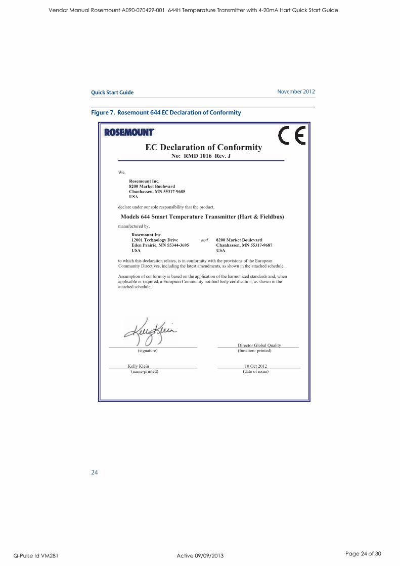
Figure 7. Rosemount 644 EC Declaration of Conformity
EC Declaration of Conformity No: RMD 1016 Rev. J
Director Global Quality
(signature) (function- printed)
Kelly Klein 10 Oct 2012
(name-printed) (date of issue)
We,
Rosemount Inc.
8200 Market Boulevard
Chanhassen, MN 55317-9685
USA
declare under our sole responsibility that the product,
Models 644 Smart Temperature Transmitter (Hart & Fieldbus)
manufactured by,
Rosemount Inc.
12001 Technology Drive and 8200 Market Boulevard
Eden Prairie, MN 55344-3695 Chanhassen, MN 55317-9687
USA USA
to which this declaration relates, is in conformity with the provisions of the European
Community Directives, including the latest amendments, as shown in the attached schedule.
Assumption of conformity is based on the application of the harmonized standards and, when
applicable or required, a European Community notified body certification, as shown in the
attached schedule.
Vendor Manual Rosemount A090-070429-001 644H Temperature Transmitter with 4-20mA Hart Quick Start Guide
Q-Pulse Id VM281 Active 09/09/2013 Page 24 of 30
Quick Start Guide
25
November 2012
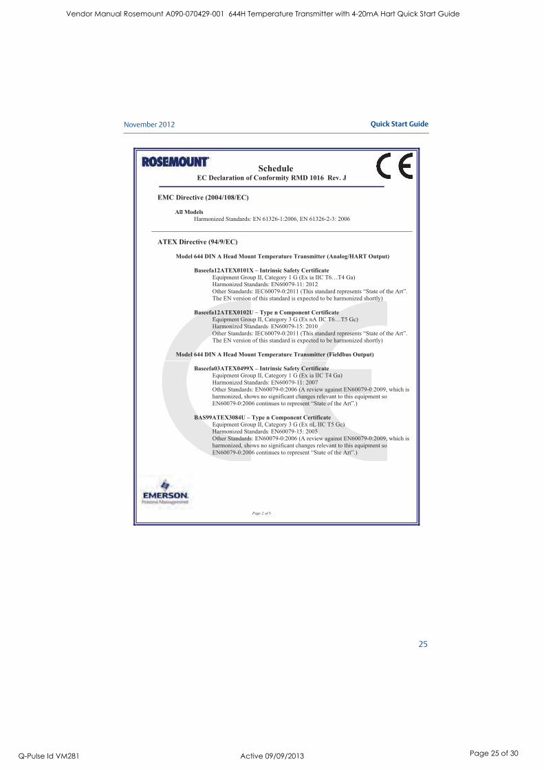
ScheduleEC Declaration of Conformity RMD 1016 Rev. J
Page 2 of 5
EMC Directive (2004/108/EC)
All Models
Harmonized Standards: EN 61326-1:2006, EN 61326-2-3: 2006
ATEX Directive (94/9/EC)
Model 644 DIN A Head Mount Temperature Transmitter (Analog/HART Output)
Baseefa12ATEX0101X – Intrinsic Safety Certificate
Equipment Group II, Category 1 G (Ex ia IIC T6…T4 Ga)
Harmonized Standards: EN60079-11: 2012
Other Standards: IEC60079-0:2011 (This standard represents “State of the Art”.
The EN version of this standard is expected to be harmonized shortly)
Baseefa12ATEX0102U – Type n Component Certificate
Equipment Group II, Category 3 G (Ex nA IIC T6…T5 Gc)
Harmonized Standards: EN60079-15: 2010
Other Standards: IEC60079-0:2011 (This standard represents “State of the Art”.
The EN version of this standard is expected to be harmonized shortly)
Model 644 DIN A Head Mount Temperature Transmitter (Fieldbus Output)
Baseefa03ATEX0499X – Intrinsic Safety Certificate
Equipment Group II, Category 1 G (Ex ia IIC T4 Ga)
Harmonized Standards: EN60079-11: 2007
Other Standards: EN60079-0:2006 (A review against EN60079-0:2009, which is
harmonized, shows no significant changes relevant to this equipment so
EN60079-0:2006 continues to represent “State of the Art”.)
BAS99ATEX3084U – Type n Component Certificate
Equipment Group II, Category 3 G (Ex nL IIC T5 Gc)
Harmonized Standards: EN60079-15: 2005
Other Standards: EN60079-0:2006 (A review against EN60079-0:2009, which is
harmonized, shows no significant changes relevant to this equipment so
EN60079-0:2006 continues to represent “State of the Art”.)
Vendor Manual Rosemount A090-070429-001 644H Temperature Transmitter with 4-20mA Hart Quick Start Guide
Q-Pulse Id VM281 Active 09/09/2013 Page 25 of 30

November 2012
26
Quick Start Guide
ScheduleEC Declaration of Conformity RMD 1016 Rev. J
Page 3 of 5
Model 644 DIN A Head Mount Temperature Transmitter
(Enclosure Options J5, J6, J7, J8, R1, R2, R3, or R4)
KEMA 99ATEX8715X – Flameproof Certificate
Equipment Group II, Category 2 G (Ex d IIC T6 Gb)
Harmonized Standards: EN60079-1: 2007
Other Standards: EN60079-0:2006 (A review against EN60079-0:2009, which is
harmonized, shows no significant changes relevant to this equipment so
EN60079-0:2006 continues to represent “State of the Art”.)
KEMA 99ATEX8715X – Dust Certificate
Equipment Group II, Category 1 D (Ex tD A20 IP66 T95°C)
Harmonized Standards:
Other Standards: EN61241-0:2006, EN61241-1:2004 (A review against
EN60079-0:2009, and EN60079-31, which are harmonized, shows no significant
changes relevant to this equipment so EN61241-0:2006, EN61241-1:2004
continue to represent “State of the Art”.)
Model 644 DIN A Head Mount Temperature Transmitter
(Enclosure Options J1, J2, J3, or J4)
FMG12ATEX0065X – Flameproof Certificate
Equipment Group II, Category 2 G (Ex d IIC T6 Gb)
Harmonized Standards: EN60079-0:2009, EN60079-1: 2007
FMG12ATEX0065X – Dust Certificate
Equipment Group II, Category 2 D (Ex tb IIIC T95°C Db)
Harmonized Standards: EN60079-0:2009, and EN60079-31:2009
Model 644 DIN A Head Mount Temperature Transmitter (All Models)
BAS00ATEX3145 – Type n Certificate
Equipment Group II, Category 3 G (Ex nL IIC T5)
Harmonized Standards: EN60079-15: 2005
Other Standards: EN60079-0:2006 (A review against EN60079-0:2009, which is
harmonized, shows no significant changes relevant to this equipment so
EN60079-0:2006 continues to represent “State of the Art”.)
Vendor Manual Rosemount A090-070429-001 644H Temperature Transmitter with 4-20mA Hart Quick Start Guide
Q-Pulse Id VM281 Active 09/09/2013 Page 26 of 30

Quick Start Guide
27
November 2012
ScheduleEC Declaration of Conformity RMD 1016 Rev. J
Page 4 of 5
Models 644R Rail Mount Temperature Transmitters (Hart)
BAS00ATEX1033X – Intrinsic Safety Certificate
Equipment Group II, Category 1 G (Ex ia IIC T4 Ga)
Harmonized Standards: EN60079-11: 2007
Other Standards: EN60079-0:2006 (A review against EN60079-0:2009, which is
harmonized, shows no significant changes relevant to this equipment so
EN60079-0:2006 continues to represent “State of the Art”.)
BAS99ATEX3084U – Type n Component Certificate
Equipment Group II, Category 3 G (Ex nL IIC T5 Gc)
Harmonized Standards: EN60079-15: 2005
Other Standards: EN60079-0:2006 (A review against EN60079-0:2009, which is
harmonized, shows no significant changes relevant to this equipment so
EN60079-0:2006 continues to represent “State of the Art”.)
Vendor Manual Rosemount A090-070429-001 644H Temperature Transmitter with 4-20mA Hart Quick Start Guide
Q-Pulse Id VM281 Active 09/09/2013 Page 27 of 30

November 2012
28
Quick Start Guide
ScheduleEC Declaration of Conformity RMD 1016 Rev. J
Page 5 of 5
ATEX Notified Bodies for EC Type Examination Certificate
Baseefa [Notified Body Number: 1180]
Rockhead Business Park, Staden Lane
Buxton, Derbyshire SK17 9JN
United Kingdom
DEKRACertification B.V. [Notified Body Number: 0344]
Utrechtseweg 310, 6812 AR Arnhem
P.O. Box 5185, 6802 ED Arnhem
The Netherlands
Postbank 6794687
FM Approvals Ltd. [Notified Body Number: 1725]
1 Windsor Dials
Windsor, Berkshire, SL4 1RS
United Kingdom
ATEX Notified Body for Quality AssuranceBaseefa [Notified Body Number: 1180]
Rockhead Business Park, Staden Lane
Buxton, Derbyshire SK17 9JN
United Kingdom
Vendor Manual Rosemount A090-070429-001 644H Temperature Transmitter with 4-20mA Hart Quick Start Guide
Q-Pulse Id VM281 Active 09/09/2013 Page 28 of 30

Quick Start Guide
29
November 2012
Vendor Manual Rosemount A090-070429-001 644H Temperature Transmitter with 4-20mA Hart Quick Start Guide
Q-Pulse Id VM281 Active 09/09/2013 Page 29 of 30
Rosemount Inc.8200 Market BoulevardChanhassen, MN USA 55317T (US) (800) 999-9307T (Intnl) (952) 906-8888F (952) 906-8889
Emerson Process Management (India) Private Ltd.Delphi Building, B Wing, 6th FloorHiranandani Gardens, PowaiMumbai 400076, IndiaT (91) 22 6662-0566F (91) 22 6662-0500
Emerson Process ManagementAsia Pacific Private Limited1 Pandan CrescentSingapore 128461T (65) 6777 8211F (65) 6777 0947/65 6777 0743
Emerson Process Management, BrazilAv. Hollingsworth, 325 - IporangaSorocaba, SP – 18087-000, BrazilT (55) 15 3238-3788F (55) 15 3228-3300
Emerson Process Management GmbH & Co. OHGArgelsrieder Feld 382234 Wessling GermanyT 49 (8153) 9390, F49 (8153) 939172
Emerson Process Management, Russia29 Komsomolsky prospektChelyabinsk, 454138RussiaT (7) 351 798 8510F (7) 351 741 8432
Beijing Rosemount Far East Instrument Co., LimitedNo. 6 North Street, Hepingli, Dong Cheng DistrictBeijing 100013, ChinaT (86) (10) 6428 2233F (86) (10) 6422 8586
Emerson Process Management, DubaiEmerson FZEP.O. Box 17033,Jebel Ali Free Zone - South 2Dubai, U.A.E.T (971) 4 8118100F (971) 4 8865465
© 2012 Rosemount Inc. All rights reserved. All marks property of owner. The Emerson logo is a trade mark and service mark of Emerson Electric CoRosemount and the Rosemount logotype are registered trademarks of Rosemount Inc.
Quick Start Guide
00825-0200-4728, Rev ACNovember 2012
¢00825-0100-4007I¤
Vendor Manual Rosemount A090-070429-001 644H Temperature Transmitter with 4-20mA Hart Quick Start Guide
Q-Pulse Id VM281 Active 09/09/2013 Page 30 of 30