Quiz I Fall 2016 - Rensselaer Polytechnic Institute Quiz 1... · Quiz I Fall 2016 Name _____...
39
K. Connor, J. Braunstein - 1 - Revised: 17 October 2016 Rensselaer Polytechnic Institute Troy, New York, USA Quiz I Fall 2016 Name ________________________________ Section 1 (12 – 1:50PM, Monday and Thursday) Part B (80 Points) 1. (10 Pts) _________ 2. (16 Pts) _________ 3. (10 Pts) _________ 4. (5 Pts) _________ 5. (9 Pts) _________ 6. (10 Pts) _________ 7. (16 Pts) _________ 8. (4 Pts) _________ Total __________________ Draw circuit diagrams for all problems, especially as you simplify the circuits. Be sure to fully annotate plots, even when the problem does not ask you to do this. Show all of your work. Use the backs of pages if there is not enough room on the front. Almost all problems can be solved using more than one method. Check your answers by using a second method. At least skim through the entire quiz before you begin and then start with the problems you know best. The proctor will only answer clarification questions where wording is unclear or where there may be errors/typos. No other questions will be responded to.
Transcript of Quiz I Fall 2016 - Rensselaer Polytechnic Institute Quiz 1... · Quiz I Fall 2016 Name _____...

K. Connor, J. Braunstein - 1 - Revised: 17 October 2016
Rensselaer Polytechnic Institute Troy, New York, USA
Quiz I Fall 2016
Name ________________________________
Section 1 (12 – 1:50PM, Monday and Thursday)
Part B (80 Points)
1. (10 Pts) _________
2. (16 Pts) _________
3. (10 Pts) _________
4. (5 Pts) _________
5. (9 Pts) _________
6. (10 Pts) _________
7. (16 Pts) _________
8. (4 Pts) _________
Total __________________
Draw circuit diagrams for all problems, especially as you simplify the circuits.
Be sure to fully annotate plots, even when the problem does not ask you to do this.
Show all of your work. Use the backs of pages if there is not enough room on the front.
Almost all problems can be solved using more than one method. Check your answers by
using a second method.
At least skim through the entire quiz before you begin and then start with the problems
you know best.
The proctor will only answer clarification questions where wording is unclear or where
there may be errors/typos. No other questions will be responded to.

ECSE-1010 Quiz 1 Fall 2016
1 October 2016 2 K. Connor, J. Braunstein
Reginald Fessenden (October 6, 1866 – July 22, 1932) was a Canadian inventor who performed
pioneering experiments in radio, including the use of continuous waves and the early— maybe
the first—radio transmissions of voice and music. In his later career he received hundreds
of patents for devices in fields such as high-powered transmitting, sonar, and television.
As reported by the Museum of Radio and Technology: “For their entire careers, the ‘Sparks’, the
ship wireless operators for the United Fruit Company, along with the US Navy, had only heard
Morse code "dit - dahs" coming through their headphones. They had been alerted a few days
earlier for a special message to come at 9 PM Eastern Time on Christmas Eve (1906). Suddenly
they heard something that made some think they were dreaming, a human voice coming from
those headphones. Then they heard singing. There was a violin solo. Then a man made a speech.
Some called their captain and ship's officers to come and listen.
The genius responsible was Reginald Fessenden. He had succeeded in transmitting voice and
music over the air. Fessenden himself played a violin solo of ‘O Holy Night’ accompanying
himself as he sang the last verse. He also read the Biblical account of the birth of Christ from
Luke chapter 2 over the air. The text of the angels' song ‘Glory to God in the Highest - and on
Earth - Peace to Men of Goodwill’ was heard as if by miracle.
At the conclusion, Fessenden wished all a Merry Christmas and invited the Sparks to write him
at Brant Rock, Massachusetts with reception reports. Reports were received from ships along the
Atlantic northeast coast and from shore stations as far south as Norfolk, Virginia. A repeat
broadcast on New Year's Eve was heard as far south as the West Indies.”
This broadcast event was named an IEEE milestone (with plaque) in 2008.
The radio tower was
destroyed in 1971, but
the base remains in the
Blackman’s Point RV
Park in Brant Rock, MA
ECSE-1010 Quiz 1 Fall 2016
1 October 2016 3 K. Connor, J. Braunstein
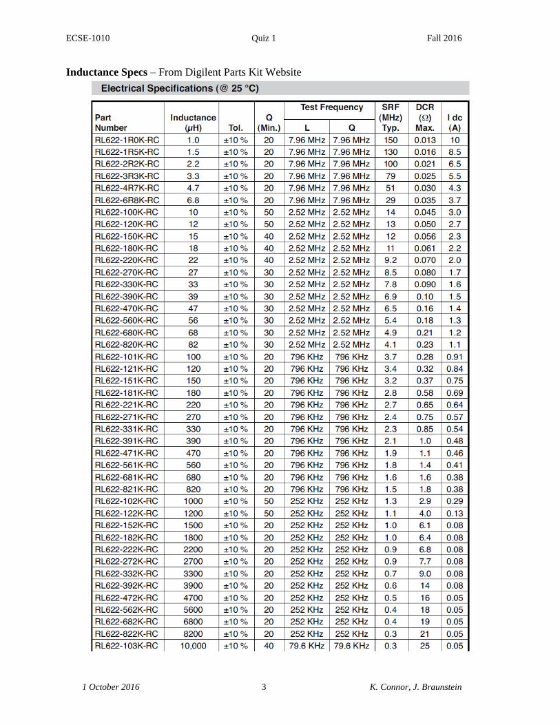
Inductance Specs – From Digilent Parts Kit Website

ECSE-1010 Quiz 1 Fall 2016
1 October 2016 4 K. Connor, J. Braunstein

ECSE-1010 Quiz 1 Fall 2016
1 October 2016 5 K. Connor, J. Braunstein
Problem 1 (10 Points) – Basic Voltage Divider
A voltage divider consisting of two resistors and a DC
voltage source is configured as shown.
a. Determine the output voltage across R2 (in Volts)
b. Determine the power delivered to resistor R1 (in milli-
Watts)
Problem 2 (16 Points) – A Bit More Complicated Voltage Divider
A somewhat more complicated voltage divider,
consisting of more than the usual two resistors
and DC source, is configured as shown.
a. Determine the voltages at B and D (in
Volts)
b. Determine the current through R5 (in
mA)

ECSE-1010 Quiz 1 Fall 2016
1 October 2016 6 K. Connor, J. Braunstein
The circuit is modified by replacing the 12kΩ resistors R3 and R2 with 1.2MΩ and the 1kΩ
resistor R5 with 4kΩ.
c. Determine the voltages at B and D.
d. Determine the current through R5.

ECSE-1010 Quiz 1 Fall 2016
1 October 2016 7 K. Connor, J. Braunstein
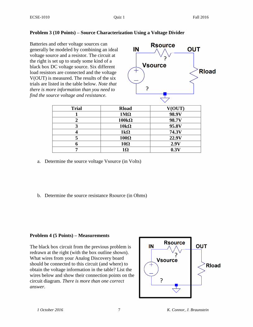
Problem 3 (10 Points) – Source Characterization Using a Voltage Divider
Batteries and other voltage sources can
generally be modeled by combining an ideal
voltage source and a resistor. The circuit at
the right is set up to study some kind of a
black box DC voltage source. Six different
load resistors are connected and the voltage
V(OUT) is measured. The results of the six
trials are listed in the table below. Note that
there is more information than you need to
find the source voltage and resistance.
Trial Rload V(OUT)
1 1MΩ 110.9V
2 100kΩ 110.3V
3 10kΩ 104.1V
4 1kΩ 66.6V
5 100Ω 14.5V
6 10Ω 1.6V
7 1Ω 0.2V
a. Determine the source voltage Vsource (in Volts)
b. Determine the source resistance Rsource (in Ohms)
Problem 4 (5 Points) – Measurements
The black box circuit from the previous problem is
redrawn at the right (with the box outline shown).
What wires from your Analog Discovery board
should be connected to this circuit (and where) to
obtain the voltage information in the table? List the
wires below and show their connection points on the
circuit diagram. There is more than one correct
answer.
?
?
?
?

ECSE-1010 Quiz 1 Fall 2016
1 October 2016 8 K. Connor, J. Braunstein
Problem 5 (9 Points) – Resistor Ladder Circuit
A more complex circuit is formed by essentially connecting a bunch of voltage dividers. The
voltage source is 84V DC, so that is the voltage at A. The remainder of the circuit is built with
resistor values, 1kΩ, 2kΩ and 40kΩ.
a. (2 pts) Before beginning the analysis of this circuit, answer the following two general
questions:
a. What is the approximate value for the series combination of two resistors, R1 and
R2, when R1 >> R2?
b. What is the approximate value for the parallel combination of two resistors, R1
and R2, when R1 >> R2?
b. (2 pts) The circuit above was designed without checking to be sure the resistor values
chosen were standard values. Check the values selected and change any non-standard
values to the closest standard value and indicate the changes on the circuit diagram.
c. (3 pts) Using your modified circuit and the approximations of part a, find the voltages at
nodes B, C, D. This will give you reasonable estimates of the actual voltages.
d. (2 pts) Assume that you were able to measure the actual voltages only at nodes B and C
and found them to be 68.0V and 39.6V, respectively. Determine the voltage at node D.
Compare the three actual voltages to your approximate calculations.

ECSE-1010 Quiz 1 Fall 2016
1 October 2016 9 K. Connor, J. Braunstein

ECSE-1010 Quiz 1 Fall 2016
1 October 2016 10 K. Connor, J. Braunstein
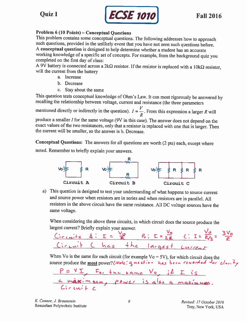
Problem 6 (10 Points) – Conceptual Questions
This problem contains some conceptual questions. The following addresses how to approach
such questions, provided in the unlikely event that you have not seen such questions before.
A conceptual question is designed to help determine whether a student has an accurate
working knowledge of a specific set of concepts. For example, from the background quiz you
completed on the first day of class:
A 9V battery is connected across a 2kΩ resistor. If the resistor is replaced with a 10kΩ resistor,
will the current from the battery
a. Increase
b. Decrease
c. Stay about the same
This question tests conceptual knowledge of Ohm’s Law. It can most rigorously be answered by
recalling the relationship between voltage, current and resistance (the three parameters
mentioned directly or indirectly in the question). R
VI . From this expression a larger R will
produce a smaller I for the same voltage (9V in this case). The answer does not depend on the
exact values of the two resistances, only that a resistor is replaced with one that is larger. Then
the current will be smaller, so the answer is b. Decrease.
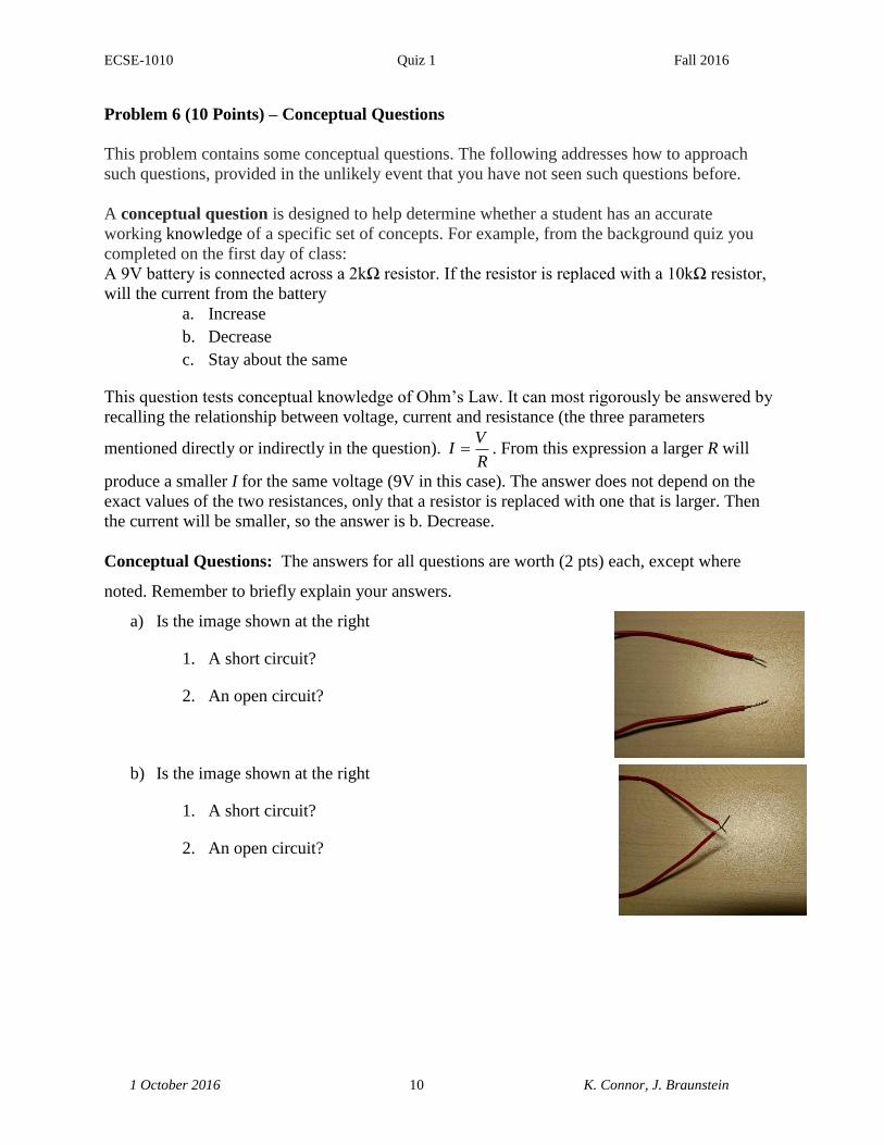
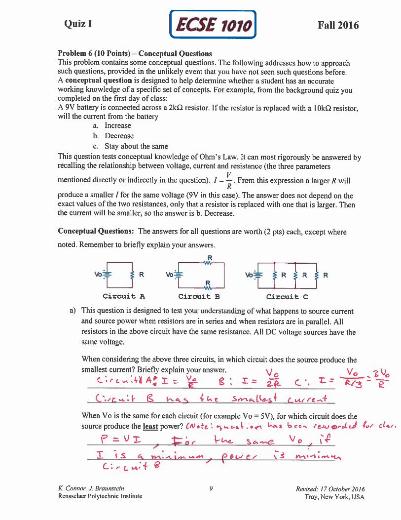
Conceptual Questions: The answers for all questions are worth (2 pts) each, except where
noted. Remember to briefly explain your answers.
a) Is the image shown at the right
1. A short circuit?
2. An open circuit?
b) Is the image shown at the right
1. A short circuit?
2. An open circuit?

ECSE-1010 Quiz 1 Fall 2016
1 October 2016 11 K. Connor, J. Braunstein
c) In the standard voltage divider configuration shown at the
right, resistor R1 is much larger than resistor R2. Is the power
dissipated in R1
1. Much greater than the power dissipated in R2
2. Much less than the power dissipated in R2
3. About the same as the power dissipated in R2
d) In the circuit at the right, two resistors (R1 much larger
than R2) are connected in parallel across a voltage
source V. Is the power dissipated in R1
1. Much greater than the power dissipated in R2
2. Much less than the power dissipated in R2
3. About the same as the power dissipated in R2
e) The LT-Spice generated signal shown above consists of two sinusoidal voltage waves
with different frequencies. What are the two frequencies? The vertical scale is
100mV/Div and the horizontal scale is 0.3ms/Div. Circle the correct answers.
500Hz
1kHz
2kHz
2.5kHz
5kHz
10kHz
20kHz
25kHz

ECSE-1010 Quiz 1 Fall 2016
1 October 2016 - 12 - K. Connor, J. Braunstein
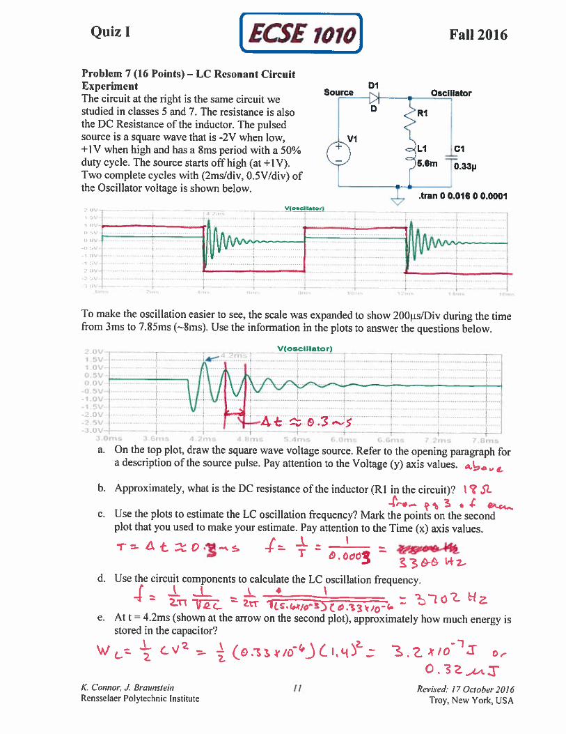
Problem 7 (16 Points) – LC Resonant Circuit Experiment
The circuit at the right is similar
to the one we studied in classes
5 and 7. A different inductor (L
is given) and a different
capacitor (C is unknown) are
used. The resistance is also the
DC Resistance of the inductor
(also not given in the figure).
The pulsed source is a square
wave that is -3V when low and
+1V when high. Two complete
cycles of the Source and
Oscillator voltages are shown
below. The time scale is
2ms/Div and the voltage scale is
0.5V/Div. Recall that there are 10 divisions both horizontally and vertically.
To make the oscillation easier to see, the scale was expanded to show 200µs/Div during the time
from 8mss to 12ms. Use the information in plots to answer the following:
a. What is the frequency of the Source square wave voltage?
b. What is the frequency of the damped oscillation voltage? Hint: Can be found 2 ways.
c. What is the value of the capacitance? Hint: The capacitor value is not standard.
d. What is the value of the resistance? Hint: The inductor is a standard component.
?
?

ECSE-1010 Quiz 1 Fall 2016
1 October 2016 - 13 - K. Connor, J. Braunstein
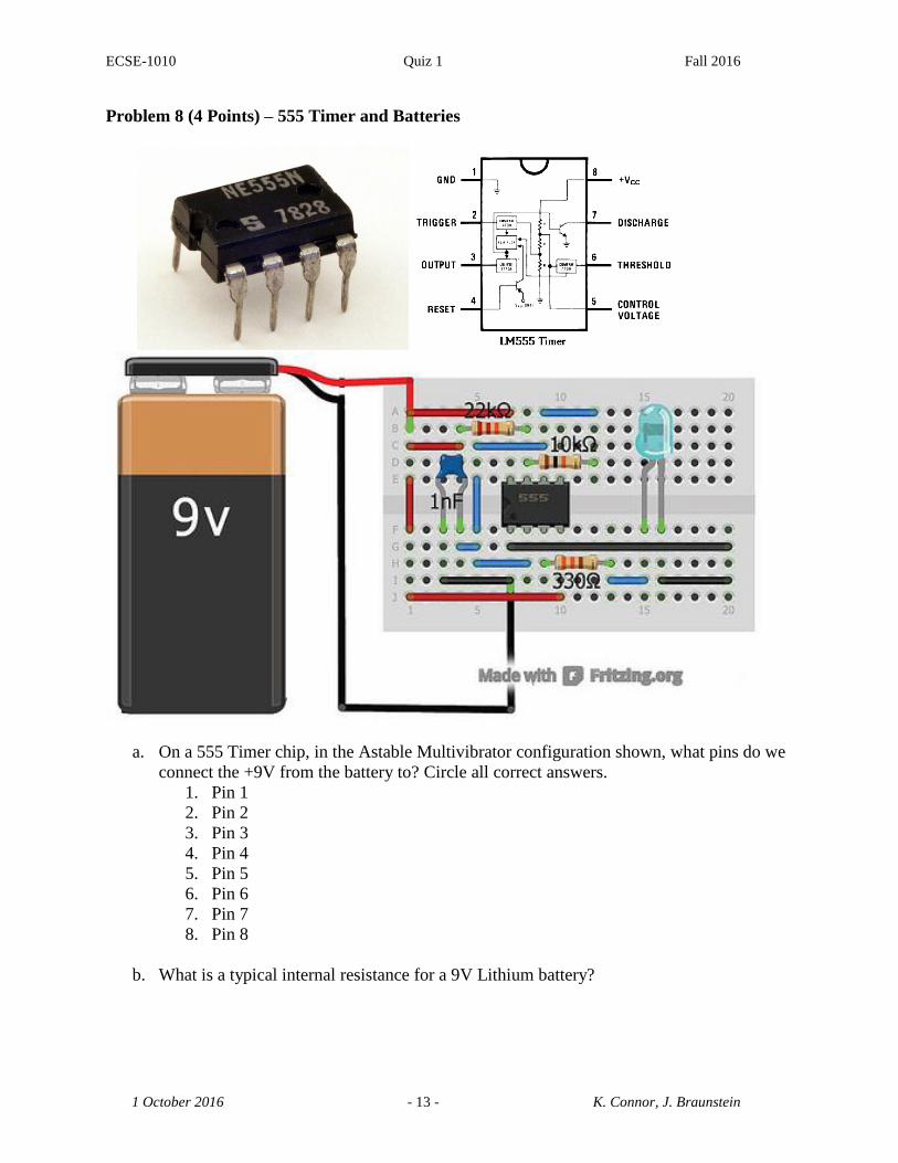
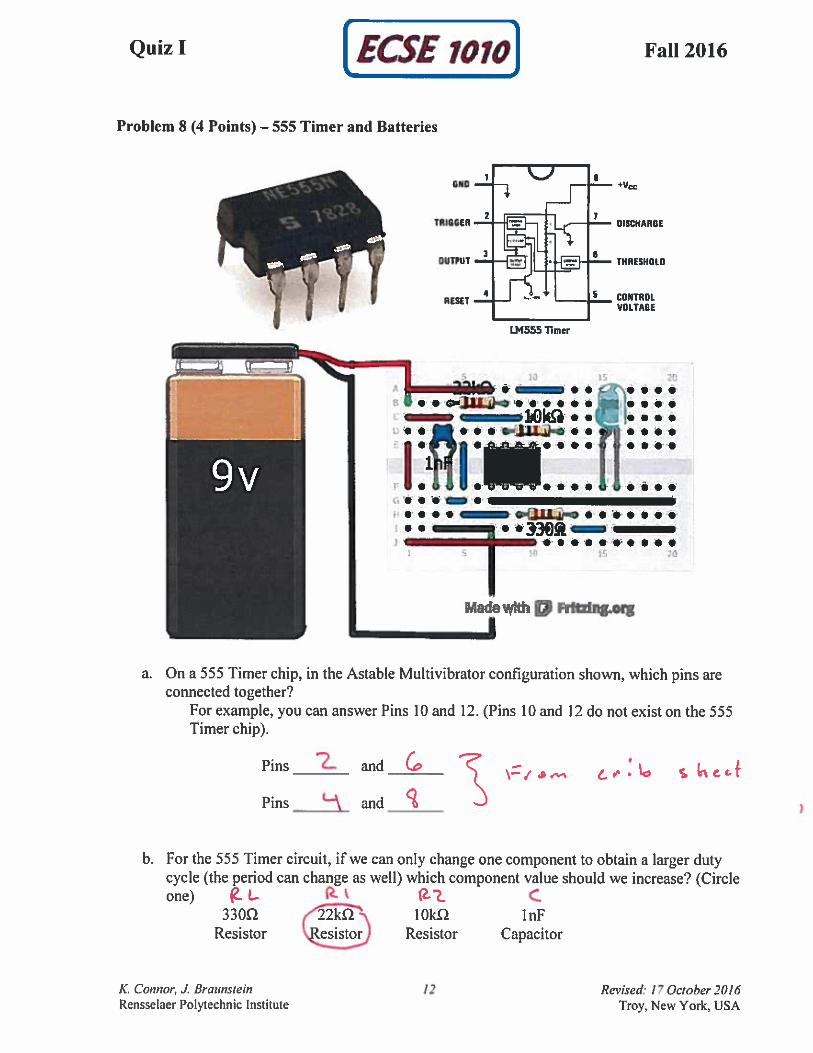
Problem 8 (4 Points) – 555 Timer and Batteries
a. On a 555 Timer chip, in the Astable Multivibrator configuration shown, what pins do we
connect the +9V from the battery to? Circle all correct answers.
1. Pin 1
2. Pin 2
3. Pin 3
4. Pin 4
5. Pin 5
6. Pin 6
7. Pin 7
8. Pin 8
b. What is a typical internal resistance for a 9V Lithium battery?

K. Connor, J. Braunstein - 1 - Revised: 17 October 2016
Rensselaer Polytechnic Institute Troy, New York, USA
Quiz I Fall 2016
Name ________________________________
Section 2 (4 – 5:50PM, Monday and Thursday)
Part B (80 Points)
1. (10 Pts) _________
2. (16 Pts) _________
3. (10 Pts) _________
4. (5 Pts) _________
5. (9 Pts) _________
6. (10 Pts) _________
7. (16 Pts) _________
8. (4 Pts) _________
Total __________________
Draw circuit diagrams for all problems, especially as you simplify the circuits.
Be sure to fully annotate plots, even when the problem does not ask you to do this.
Show all of your work. Use the backs of pages if there is not enough room on the front.
Almost all problems can be solved using more than one method. Check your answers by
using a second method.
At least skim through the entire quiz before you begin and then start with the problems
you know best.
The proctor will only answer clarification questions where wording is unclear or where
there may be errors/typos. No other questions will be responded to.

ECSE-1010 Quiz 1 Fall 2016
1 October 2016 2 K. Connor, J. Braunstein
Reginald Fessenden (October 6, 1866 – July 22, 1932) was a Canadian inventor who performed
pioneering experiments in radio, including the use of continuous waves and the early— maybe
the first—radio transmissions of voice and music. In his later career he received hundreds
of patents for devices in fields such as high-powered transmitting, sonar, and television.
As reported by the Museum of Radio and Technology: “For their entire careers, the ‘Sparks’, the
ship wireless operators for the United Fruit Company, along with the US Navy, had only heard
Morse code "dit - dahs" coming through their headphones. They had been alerted a few days
earlier for a special message to come at 9 PM Eastern Time on Christmas Eve (1906). Suddenly
they heard something that made some think they were dreaming, a human voice coming from
those headphones. Then they heard singing. There was a violin solo. Then a man made a speech.
Some called their captain and ship's officers to come and listen.
The genius responsible was Reginald Fessenden. He had succeeded in transmitting voice and
music over the air. Fessenden himself played a violin solo of ‘O Holy Night’ accompanying
himself as he sang the last verse. He also read the Biblical account of the birth of Christ from
Luke chapter 2 over the air. The text of the angels' song ‘Glory to God in the Highest - and on
Earth - Peace to Men of Goodwill’ was heard as if by miracle.
At the conclusion, Fessenden wished all a Merry Christmas and invited the Sparks to write him
at Brant Rock, Massachusetts with reception reports. Reports were received from ships along the
Atlantic northeast coast and from shore stations as far south as Norfolk, Virginia. A repeat
broadcast on New Year's Eve was heard as far south as the West Indies.”
This broadcast event was named an IEEE milestone (with plaque) in 2008.
The radio tower was
destroyed in 1971, but
the base remains in the
Blackman’s Point RV
Park in Brant Rock, MA

ECSE-1010 Quiz 1 Fall 2016
1 October 2016 3 K. Connor, J. Braunstein
Inductance Specs – From Digilent Parts Kit Website
ECSE-1010 Quiz 1 Fall 2016
1 October 2016 4 K. Connor, J. Braunstein

ECSE-1010 Quiz 1 Fall 2016
1 October 2016 5 K. Connor, J. Braunstein
Problem 1 (10 Points) – Basic Voltage Divider
A voltage divider consisting of two resistors and a DC
voltage source is configured as shown.
a. Determine the output voltage across R2 (in Volts)
b. Determine the power delivered to the load R2 (in milli-
Watts)
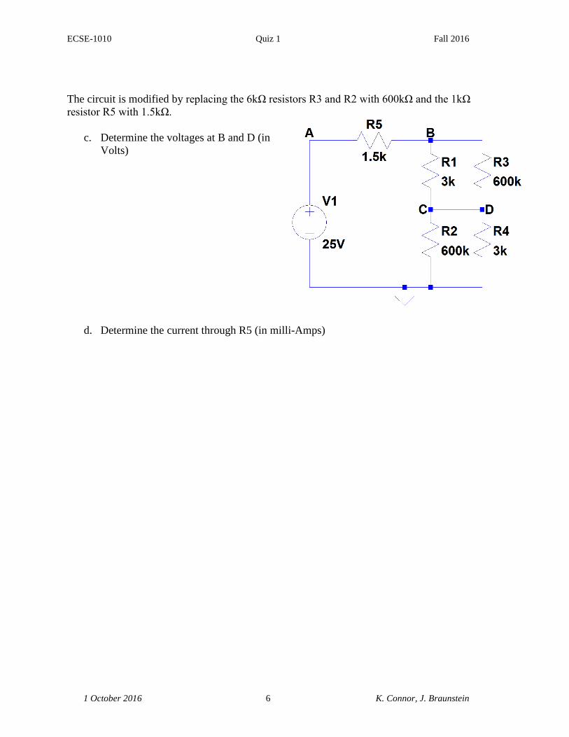
Problem 2 (16 Points) – A Bit More Complicated Voltage Divider
A somewhat more complicated voltage divider,
consisting of more than the usual two resistors and
DC source, is configured as shown.
a. Determine the voltages at B and D (in
Volts)
b. Determine the current through R5 (in milli-Amps)
ECSE-1010 Quiz 1 Fall 2016
1 October 2016 6 K. Connor, J. Braunstein
The circuit is modified by replacing the 6kΩ resistors R3 and R2 with 600kΩ and the 1kΩ
resistor R5 with 1.5kΩ.
c. Determine the voltages at B and D (in
Volts)
d. Determine the current through R5 (in milli-Amps)
ECSE-1010 Quiz 1 Fall 2016
1 October 2016 7 K. Connor, J. Braunstein
Problem 3 (10 Points) – Source Characterization Using a Voltage Divider
Batteries and other voltage sources can
generally be modeled by combining an ideal
voltage source and a resistor. The circuit at
the right is set up to study some kind of a
black box DC voltage source. Six different
load resistors are connected and the voltage
V(OUT) is measured. The results of the six
trials are listed in the table below. Note that
there is more information than you need to
find the source voltage and resistance.
Trial Rload V(OUT)
1 1MΩ 98.9V
2 100kΩ 98.7V
3 10kΩ 95.8V
4 1kΩ 74.3V
5 100Ω 22.9V
6 10Ω 2.9V
7 1Ω 0.3V
a. Determine the source voltage Vsource (in Volts)
b. Determine the source resistance Rsource (in Ohms)
Problem 4 (5 Points) – Measurements
The black box circuit from the previous problem is
redrawn at the right (with the box outline shown).
What wires from your Analog Discovery board
should be connected to this circuit (and where) to
obtain the voltage information in the table? List the
wires below and show their connection points on the
circuit diagram. There is more than one correct
answer.
?
?
?
?

ECSE-1010 Quiz 1 Fall 2016
1 October 2016 8 K. Connor, J. Braunstein
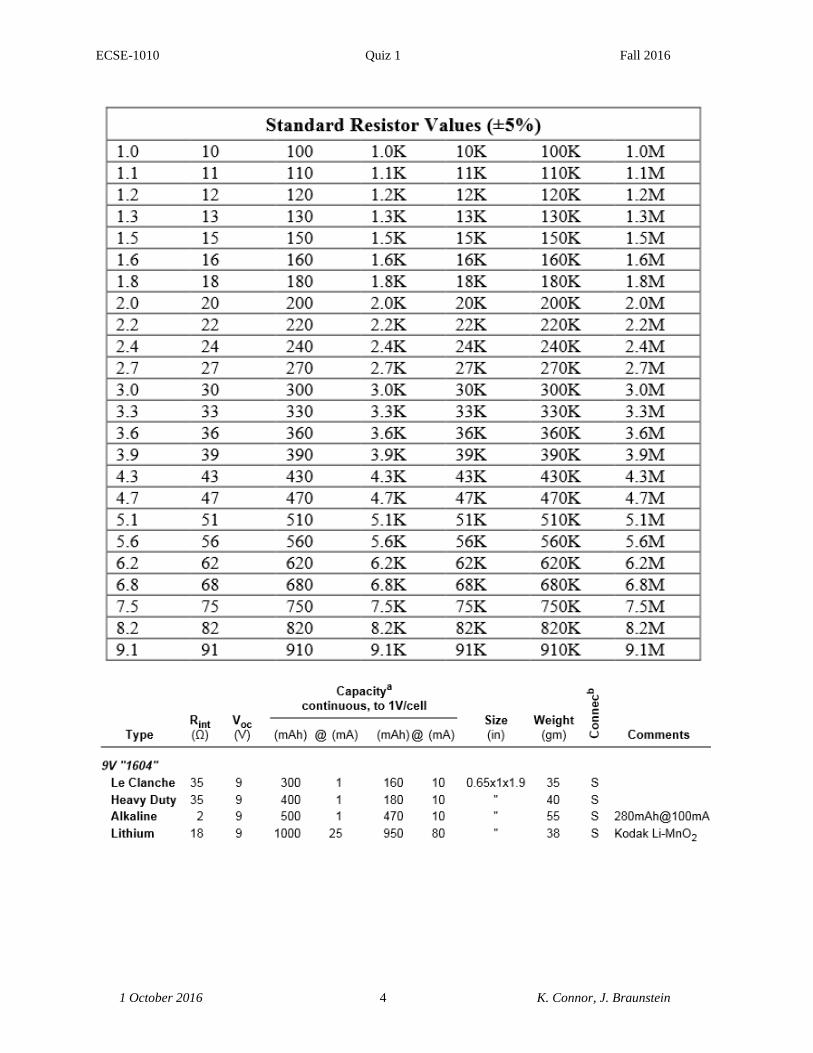
Problem 5 (9 Points) – Resistor Ladder Circuit
A more complex circuit is formed by essentially connecting a bunch of voltage dividers. The
voltage source is 126V DC, so that is the voltage at A. The remainder of the circuit is built with
resistor values: 1kΩ, 2kΩ, 3kΩ and 50kΩ.
a. (2 pts) Before beginning the analysis of this circuit, answer the following two general
questions:
a. What is the approximate value for the series combination of two resistors, R1 and
R2, when R1 >> R2?
b. What is the approximate value for the parallel combination of two resistors, R1
and R2, when R1 >> R2?
b. (2 pts) The circuit above was designed without checking to be sure the resistor values
chosen were standard values. Check the values selected and change any non-standard
values to the closest standard value and indicate the changes on the circuit diagram.
c. (3 pts) Using your modified circuit and the approximations of part a, find the voltages at
nodes B, C, D). This will give you reasonable estimates of the actual voltages.
d. (2 pts) Assume that you built the circuit and were able to measure the actual voltages
only at nodes B and C and (69.1V and 33.9V, respectively). Determine the voltage at
node D. Compare the three actual voltages to your approximate calculations.

ECSE-1010 Quiz 1 Fall 2016
1 October 2016 9 K. Connor, J. Braunstein
ECSE-1010 Quiz 1 Fall 2016
1 October 2016 10 K. Connor, J. Braunstein
Problem 6 (10 Points) – Conceptual Questions
This problem contains some conceptual questions. The following addresses how to approach
such questions, provided in the unlikely event that you have not seen such questions before.
A conceptual question is designed to help determine whether a student has an accurate
working knowledge of a specific set of concepts. For example, from the background quiz you
completed on the first day of class:
A 9V battery is connected across a 2kΩ resistor. If the resistor is replaced with a 10kΩ resistor,
will the current from the battery
a. Increase
b. Decrease
c. Stay about the same
This question tests conceptual knowledge of Ohm’s Law. It can most rigorously be answered by
recalling the relationship between voltage, current and resistance (the three parameters
mentioned directly or indirectly in the question). R
VI . From this expression a larger R will
produce a smaller I for the same voltage (9V in this case). The answer does not depend on the
exact values of the two resistances, only that a resistor is replaced with one that is larger. Then
the current will be smaller, so the answer is b. Decrease.
Conceptual Questions: The answers for all questions are worth (2 pts) each, except where
noted. Remember to briefly explain your answers.
a) Is the image shown at the right
1. A short circuit?
2. An open circuit?
b) Is the image shown at the right
1. A short circuit?
2. An open circuit?

ECSE-1010 Quiz 1 Fall 2016
1 October 2016 11 K. Connor, J. Braunstein
c) In the standard voltage divider configuration shown at the
right, resistor R1 is much larger than resistor R2. Is the power
dissipated in R1
1. Much greater than the power dissipated in R2
2. Much less than the power dissipated in R2
3. About the same as the power dissipated in R2
d) In the circuit at the right, two resistors (R1 much larger
than R2) are connected in parallel across a voltage
source V. Is the power dissipated in R1
1. Much greater than the power dissipated in R2
2. Much less than the power dissipated in R2
3. About the same as the power dissipated in R2
e) The LT-Spice generated signal shown above consists of two sinusoidal voltage waves
with different frequencies. What are the two frequencies? The vertical scale is
100mV/Div and the horizontal scale is 0.3ms/Div. Circle the correct answers.
500Hz
1kHz
2kHz
2.5kHz
5kHz
10kHz
20kHz
25kHz

ECSE-1010 Quiz 1 Fall 2016
1 October 2016 - 12 - K. Connor, J. Braunstein
Problem 7 (16 Points) – LC Resonant Circuit Experiment
The circuit at the right is similar
to the one we studied in classes
5 and 7. A different inductor (L
is given) and a different
capacitor (C is unknown) are
used. The resistance is also the
DC Resistance of the inductor
(also not given in the figure).
The pulsed source is a square
wave that is -3V when low and
+1V when high. Two complete
cycles of the Source and
Oscillator voltages are shown
below. The time scale is
2ms/Div and the voltage scale is
0.5V/Div. Recall that there are 10 divisions both horizontally and vertically.
To make the oscillation easier to see, the scale was expanded to show 200µs/Div during the time
from 8mss to 12ms. Use the information in plots to answer the following:
a. What is the frequency of the Source square wave voltage?
b. What is the frequency of the damped oscillation voltage? Hint: Can be found 2 ways.
c. What is the value of the capacitance? Hint: The capacitor value is not standard.
d. What is the value of the resistance? Hint: The inductor is a standard component.
?
?
ECSE-1010 Quiz 1 Fall 2016
1 October 2016 - 13 - K. Connor, J. Braunstein
Problem 8 (4 Points) – 555 Timer and Batteries
a. On a 555 Timer chip, in the Astable Multivibrator configuration shown, what pins do we
connect the +9V from the battery to? Circle all correct answers.
1. Pin 1
2. Pin 2
3. Pin 3
4. Pin 4
5. Pin 5
6. Pin 6
7. Pin 7
8. Pin 8
b. What is a typical internal resistance for a 9V Lithium battery?
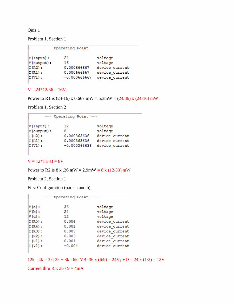
Quiz 1
Problem 1, Section 1
V = 24*12/36 = 16V
Power to R1 is (24-16) x 0.667 mW = 5.3mW = (24/36) x (24-16) mW
Problem 1, Section 2
V = 12*11/33 = 8V
Power to R2 is 8 x .36 mW = 2.9mW = 8 x (12/33) mW
Problem 2, Section 1
First Configuration (parts a and b)
12k || 4k = 3k; 3k + 3k =6k; VB=36 x (6/9) = 24V; VD = 24 x (1/2) = 12V
Current thru R5: 36 / 9 = 4mA
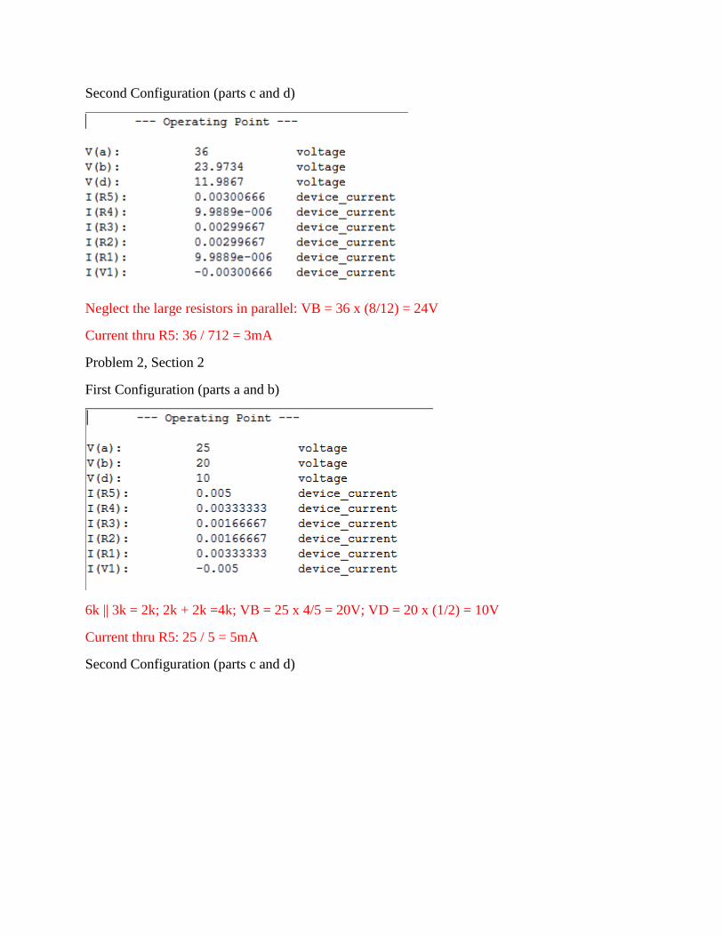
Second Configuration (parts c and d)
Neglect the large resistors in parallel: VB = 36 x (8/12) = 24V
Current thru R5: 36 / 712 = 3mA
Problem 2, Section 2
First Configuration (parts a and b)
6k || 3k = 2k; 2k + 2k =4k; VB = 25 x 4/5 = 20V; VD = 20 x (1/2) = 10V
Current thru R5: 25 / 5 = 5mA
Second Configuration (parts c and d)

Neglect the large resistors in parallel: VB = 25 x (6/7.5) = 20V
Current thru R5: 25 / 7.5 = 3.33mA
Problem 3, Section 1
The source voltage and resistance are shown below.
For the source voltage, use the largest value of the load resistance, because 1M is very large. We
will check it later. Then Vsource = 111V
For the resistance, take one of the smaller loads where the voltage is about half of the source.
Here we choose 1k and 66.6V. R = (111/66.6) x 1000 – 1000 = 666. We can check another
voltage to be sure that these are correct. Choose 100 and 14.5V. R = (111/14.5) x 100 – 100 =
666 which checks.
Problem 3, Section 2
The source voltage and resistance are shown below
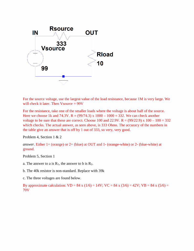
For the source voltage, use the largest value of the load resistance, because 1M is very large. We
will check it later. Then Vsource = 99V
For the resistance, take one of the smaller loads where the voltage is about half of the source.
Here we choose 1k and 74.3V. R = (99/74.3) x 1000 – 1000 = 332. We can check another
voltage to be sure that these are correct. Choose 100 and 22.9V. R = (99/22.9) x 100 – 100 = 332
which checks. The actual answer, as seen above, is 333 Ohms. The accuracy of the numbers in
the table give an answer that is off by 1 out of 333, so very, very good.
Problem 4, Section 1 & 2
answer. Either 1+ (orange) or 2+ (blue) at OUT and 1- (orange-white) or 2- (blue-white) at
ground.
Problem 5, Section 1
a. The answer to a is R1, the answer to b is R2.
b. The 40k resistor is non-standard. Replace with 39k
c. The three voltages are found below.
By approximate calculation: VD = 84 x (1/6) = 14V; VC = 84 x (3/6) = 42V; VB = 84 x (5/6) =
70V

d. By calculation, the voltage at D is 1/3 the voltage at C: 39.6/3 = 13.2V. The voltages at B, C,
and D are all slightly smaller than in the approximate solution because the contribution from the
51k resistor reduces the overall resistance.
Problem 5, Section 2
a. The answer to a is R1, the answer to b is R2.
b. The 50k resistor is non-standard. Replace with 51k
c. The three voltages are found below.
By approximate calculation: VD = 126 x (1/7) = 18V; VC = 126 x (2/7) = 36V; VB = 84 x (4/7)
= 72V
d. By calculation, the voltage at D is ½ the voltage at C: 33.9/2 = 17 (close answers are OK). The
voltages at B, C, and D are all slightly smaller than in the approximate solution because the
contribution from the 51k resistor reduces the overall resistance.


![Spring fall hub quiz [Set-1]](https://static.fdocuments.in/doc/165x107/5888c15c1a28ab200f8b5611/spring-fall-hub-quiz-set-1.jpg)