Quintex Cervical Plating System
28
Quintex ™ Cervical Plating System Surgical Technique Aesculap Spine
Transcript of Quintex Cervical Plating System

Quintex™ Cervical Plating SystemSurgical Technique
Aesculap Spine

2
Quintex™ Cervical Plating SystemSurgical Technique
I. Indications and Contraindications . . . . . . . . . . . . . . . . . . . . . . . . . . . . . 3
II. Warnings and Precautions . . . . . . . . . . . . . . . . . . . . . . . . . . . . . . . . . . . 4
III. Construct Options . . . . . . . . . . . . . . . . . . . . . . . . . . . . . . . . . . . . . . . . . . 4
IV. Surgical Technique . . . . . . . . . . . . . . . . . . . . . . . . . . . . . . . . . . . . . . . . . 5
1 . Surgical Approach & Preparation . . . . . . . . . . . . . . . . . . . . . . . . . . 5
2 . Interbody Insertion . . . . . . . . . . . . . . . . . . . . . . . . . . . . . . . . . . . . . 6
3 . Plate Selection . . . . . . . . . . . . . . . . . . . . . . . . . . . . . . . . . . . . . . . . . 7
4 . Plate Contouring . . . . . . . . . . . . . . . . . . . . . . . . . . . . . . . . . . . . . . . 8
5 . Plate Insertion . . . . . . . . . . . . . . . . . . . . . . . . . . . . . . . . . . . . . . . . . 9
6 . Temporary Plate Fixation . . . . . . . . . . . . . . . . . . . . . . . . . . . . . . . . . 9
7 . Screw Preparation . . . . . . . . . . . . . . . . . . . . . . . . . . . . . . . . . . . . . 10
8 . Guide Selection . . . . . . . . . . . . . . . . . . . . . . . . . . . . . . . . . . . . . . . 11
9 . OPTIONAL: Screw Hole Preparation . . . . . . . . . . . . . . . . . . . . . . . 12
10 . OPTIONAL: Drilling . . . . . . . . . . . . . . . . . . . . . . . . . . . . . . . . . . . . . 12
11 . OPTIONAL: Tapping . . . . . . . . . . . . . . . . . . . . . . . . . . . . . . . . . . . . 13
12 . Screw Selection . . . . . . . . . . . . . . . . . . . . . . . . . . . . . . . . . . . . . . . 13
13 . Screw Placement . . . . . . . . . . . . . . . . . . . . . . . . . . . . . . . . . . . . . . 14
14 . Confirmation . . . . . . . . . . . . . . . . . . . . . . . . . . . . . . . . . . . . . . . . . 15
15 . Closure and Post-operative Care . . . . . . . . . . . . . . . . . . . . . . . . . 15
16 . Implant Removal . . . . . . . . . . . . . . . . . . . . . . . . . . . . . . . . . . . . . . 16
17 . Revision Tips . . . . . . . . . . . . . . . . . . . . . . . . . . . . . . . . . . . . . . . . . . 16
18 . Instrument Disassembly . . . . . . . . . . . . . . . . . . . . . . . . . . . . . 17-18
19 . Instrument Assembly . . . . . . . . . . . . . . . . . . . . . . . . . . . . . . . . . . . 19
20 . Sterilization Recommendations . . . . . . . . . . . . . . . . . . . . . . . . . . 20
V. Implant and Instrument Overview . . . . . . . . . . . . . . . . . . . . . . . . . 21-25
Table of Contents

3
IndicationsThe Quintex™ Cervical Plating System is intended for the treatment of cervical spinal instability resulting from:
■ Degenerative disc disease (DDD) (defined as neck pain of discogenic origin with degeneration of the disc confirmed by history and radiographic studies),
■ Spondylolisthesis,■ Trauma (i .e . fracture or dislocation),■ Spinal Stenosis,■ Deformity (i .e ., scoliosis, kyphosis, and/or lordosis), ■ Tumors, ■ Pseudoarthrosis as a result of failed spine surgery,■ Failed previous fusions,■ Symptomatic cervical spondylosis■ Instability following surgery for the above indications .
Levels of anterior cervical intervertebral body screw fixation for this indication are from C2-T1 .
ContraindicationsDo not apply in the presence of:■ Fever■ Infection — Systemic — In the spine — Local■ Pregnancy■ Acute osteopenia■ Medical or surgical conditions that could negatively affect the success of the implantation■ Foreign body sensitivity to the implant materials■ Inadequate patient compliance■ Severe osteoporosis or similar loss of bone density■ Severe damage to bone structures that would prevent the stable implantation of system components■ Bone tumor in the region of implant fixation■ Anticipated excessive load on the joint implant■ Dependency on pharmaceutical drugs, drug abuse or alcoholism■ Systemic or metabolic disease(s)■ Morbid obesity (adiposity)■ Generally poor condition of the patient■ Wound healing disorders■ Neuromuscular diseases or disorders■ Mental illness
Use only within the indicated levels of the spine and for applications outlined in the Indications section .
I. Indications and Contraindications

4
Quintex™ Cervical Plating SystemSurgical Technique
II. Warnings■ The potential for success is increased by the proper selection of implant size, shape and design . Quintex system implants should
not be expected to withstand the unsupported stresses of full load bearing .■ Ensure that all necessary implants and instruments are on hand and inspected prior to use .■ Contouring of the plate should be minimized as excessive contouring can fatigue implant materials .■ The Quintex system is provided non sterile and must be sterilized prior to use . All packaging materials must be removed prior to
sterilization .■ Mixing of dissimilar metals can accelerate the corrosion process . Quintex system implants should not be mixed with implants from
any other system .■ The Quintex system should not be reused under any circumstances .■ Patient behavior can greatly affect surgical outcomes . Smokers and noncompliant patients should be advised of this fact and
warned of the increased risk of potential complications .■ Patients should be advised of the possible limitations of their implant(s), including postoperative mobility and load-bearing stress .■ This device is not approved or intended for screw attachment or fixation to the posterior elements (pedicles) of the cervical,
thoracic or lumbar spine .
For complete guidelines and labeling limitations, please consult the Quintex Cervical Plating System Instruction for Use.
The Quintex cervical plating system offers four distinct implant combinations, each with unique performance characteristics . For both plate styles, constructs may be hybridized to customize the dynamic properties at each level and accommodate patient-specific anatomical or clinical considerations .
Constrained Semiconstrained Semidynamic™ Dynamic
More Rigid More Dynamic
III. Construct Options

5
A cervical retraction system (such as Aesculap’s Caspar Cervical Retractor System) should then be used to provide adequate visualization to the front of the cervical spine . Adequate fascial plane release is important for optimal exposure .
After identification of the appropriate disc space(s) is/are confirmed via x-ray, a cervical distraction system (such as Aesculap’s Caspar Cervical Distraction System) may be used to enhance access to the disc space . (Fig . 2)
1. Surgical Approach & Preparation
Place the patient in the supine position and bolster the intrascapular region to maintain the head in slight extension . The use of a head halter attached to an outrigger for traction may also be helpful . If fluoroscopy is used, it can be utilized at this point to confirm positioning and check that desired vertebral levels can be adequately visualized .
Shoulder depression can be achieved using 3” surgical tape running from the shoulders to the foot of the bed . KERLIX™ *-style dressings attached to the wrists may allow for enhanced visualization of lower cervical vertebrae and the cervico-thoracic junction .
Utilize the standard anterior approach to the cervical spine . This can be through one of several incisions with the exposure typically medial to the carotid sheath and lateral to the trachea and esophagus . (Fig . 1)
IV. Surgical Technique
Fig . 2Fig . 1
*KERLIX is a registered trademark of a Covidien company .

6
Quintex™ Cervical Plating SystemSurgical Technique
2. Interbody Insertion
Perform a thorough discectomy (Fig . 3) and adequate neural decompression, then prepare the endplates to receive the interbody device of choice . (Fig . 4)
Aesculap offers several interbody products to restore height, lordosis and facilitate solid arthrodesis including the CeSpace™ line of interbody devices . (Fig . 5)
Please consult your Aesculap Spine Representative to learn more about these fusion interbody products .
Fig . 3 Fig . 4 Fig . 5

7
Both the Quintex Hybrid and Quintex Dynamic Plates also provide the surgeon with the ability to vary screw selection by level, enabling customization of the system’s polyaxial and translational properties .
Once the desired plating construct has been selected, the Caliper (SC421R) may be used to provide a linear measurement of the plate length .
3. Plate Selection
The Quintex™ system is designed with the patient and surgeon in mind . Its Constrained, Semiconstrained, Semidynamic and Dynamic construct options maximize intraoperative versatility and accommodate a wide range of anatomical considerations .
Each Quintex plating construct features different performance properties, and it is important to understand the performance characteristics of these implant combinations when determining the appropriate construct for the patient .
Fig . 6
Construct Implants Performance Constrained ■ Hybrid Plate (Blue) ■ Screws will not retain polyaxiality ■ Constrained Screws (Blue) ■ Screws will not translate Semiconstrained ■ Hybrid Plate (Blue) ■ Screws retain polyaxial motion until fusion occurs ■ Semiconstrained Screws (Green) ■ Screws will not translate Semidynamic ■ Dynamic Plate (Gold) ■ Screws retain polyaxial motion until fusion occurs ■ Semiconstrained Screws (Green) ■ Screws will translate with resistance in a controlled manner until fusion occurs Dynamic ■ Dynamic Plate (Gold) ■ Screws retain polyaxial motion until fusion occurs ■ Dynamic Screws (Gold) ■ Screws are free to translate without resistance until fusion occurs
Constrained Semiconstrained Semidynamic™ Dynamic
Note: Hybrid plates should be sized to encompass the desired area of fixation. Dynamic plates should be sized slightly shorter than Hybrid plates to accommodate translational settling.

8
Quintex™ Cervical Plating SystemSurgical Technique
4. Plate Contouring
Adding Lordosis
Quintex system plates are pre-contoured to approximate typical cervical anatomy . If additional contouring is required, the Plate Bender (SC420R) should be used to contour the plate as required . (Fig . 7)
Decreasing Lordosis
To decrease the lordosis, place bending wedge over the bending zone . (Fig . 8)
Fig . 8Fig . 7
Caution: The Quintex implant can be damaged due to excessive material stress. Follow these precautions while contouring plates: ■ Quintex plates should never be bent over a screw
hole. ■ Quintex plates should always be bent in one
direction only. ■ Quintex plates should never be bent back.
Note: The area on the instrument on which the lordosis of the plate can be reduced is labeled “Straighten Plate Here”.

9
5. Plate Insertion
6. Temporary Plate Fixation
Fixation Pin Inserter Assembly
■ Insert the Fixation Pin (SC410R) into the Fixation Pin instrument (SC422R) . To do this, pull back the outer sleeve of the fixation pin instrument . (Fig . 9a)
■ To secure the fixation pins, release outer sleeve of the Fixation Pin instrument (SC422R) . The outer sleeve is then pushed forward by a spring mechanism . (Fig . 9a)
Fixation Pin Insertion
Fixation Pins must be used to provide temporary fixation of Quintex system plates to the vertebral bodies . Temporary fixation prevents unintended repositioning of the plate during screw hole preparation and screw placement .
1 . Load one Fixation Pin (SC410R) into the Fixation Pin Instrument (SC422R) . See Fig . 9a and Fixation Pin Inserter Assembly instructions .
2 . Place the plate in the desired position and insert the Fixation Pin (SC410R) into the desired Fixation Pin Hole (Fig . 9b) by gently advancing the instrument until the pin is fully seated .
3 . Release the Pin .
4 . Repeat this process for each level where Fixation Pin placement is desired . At a minimum, it is recommended that the most cranial and caudal Fixation Pin Holes of the plate are utilized . (Fig . 10)
Fig . 10Fig . 9bPlate Screw Holes
Fixation Pin Holes
Note: At least two fixation pins must be inserted for a secure fixation of the Quintex plate. Use the Fixation Pin instrument (SC422R) for inserting the pins.
Fig . 9a
Note: The Quintex™ system features an optional Plate Holder (SC434R) to facilitate handling. See page 24 .
Note: Fixation Pins are removed after screw placement by reversing the Fixation Pin insertion procedure.

10
Quintex™ Cervical Plating SystemSurgical Technique
7. Screw Preparation
Preparing the holes for the Quintex screws
The holes for the self-drilling and self-tapping Quintex screws are prepared using the self-centering cortical bone center punch . Alternatively, the outer sleeve of the cortical bone center punch can also be removed and the cortical bone center punch can be used in combination with a drill guide for preparing the holes . This opens up the cortical bone layer of the vertebral body and the screw can be screwed in without drilling .
The screw hole can also be pre-drilled with the drill . To do this, position the drill with the drill guide and use it manually with a drill handle .
Fig . 11
Warning: Risk of tissue trauma and incorrect drill hole if the cortical bone center punch (without outer sleeve) is inserted! ■ Use the cortical bone center punch (without outer
sleeve) only in combination with single or double drill guides.
Warning: Incorrect drill hole if drilling is carried out without a drill guide! ■ Use the drill only in combination with the single or
double drill guide.
Warning: Incorrect drill hole if the self-centering outer sleeve of the cortical bone center punch is not used! ■ Always use the self-centering outer sleeve of the
cortical bone center punch if the cortical bone center punch is used without a drill guide.
Note: The maximum penetration depth of the cortical bone center punch with mounted sleeve is 6 mm.
Legenda. Self-centering cortical bone center punch, completeb. Self-centering cortical bone center punch, without outer sleeve
a .
b .

11
The Fixed Single Drill Guide (SC425R) and Fixed Double Drill Guide (SC426R) accommodate all of the screw hole preparation instruments with a fixed depth of 14 mm .
The guide sleeves for the single adjustable drill guide and double adjustable drill guide are interchangeable .
8. Guide Selection
Angulation
The screw insertion angle can be adjusted in a cranial and caudal holes direction as follows: - +20°/-8° for screws used in hybrid plates, - ±30° for screws used in dynamic plates .
Medial screws of multilevel plates allow for screw angle ranges as follows: - ±15° for hybrid plates, - ±30° for dynamic plates .
The screw insertion angle can also be adjusted in a medial-lateral direction: - +/- 6° for all plates in the system
Guide Selection
The Quintex™ system offers several guides to facilitate screw hole preparation and screw placement .
The Adjustable Single Drill Guide (SC423R) and Adjustable Double Drill Guide (SC424R) accommodate all of the screw hole preparation instruments with a variable depth setting .
Fig . 12
Note: Use of a guide is recommended to achieve appropriate placement of the screw holes.
Note: The fixed single drill guide and the fixed double drill guide are labeled “14 mm” on the sleeve for easier identification.
Warning: Risk of spinal cord trauma if the drill depth of the drill guide is incorrectly set! ■ Insert the cortical bone center punch or drill in the
drill guide and check the drill depth setting with a caliper or ruler.
Warning: Risk of injury to the spinal cord of the patient if the self-centering cortical bone center punch is not used or is used incorrectly! ■ Always use the self-centering cortical bone center
punch with outer sleeve to determine the correct position for piercing the cortical bone.
60°30°
30°28°
20°
8°
28°8°
20°60°
30°
30°
12
Quintex™ Cervical Plating SystemSurgical Technique
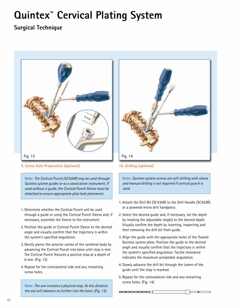
10. Drilling (optional)
1 . Attach the Drill Bit (SC430R) to the Drill Handle (SC429R) or a powered micro drill handpiece .
2 . Select the desired guide and, if necessary, set the depth by rotating the adjustable stop(s) to the desired depth . Visually confirm the depth by inserting, inspecting and then removing the drill bit from guide .
3 . Align the guide with the appropriate holes of the fixated Quintex system plate . Position the guide to the desired angle and visually confirm that the trajectory is within the system’s specified angulation . Tactile resistance indicates the maximum acceptable angulation .
4 . Slowly advance the drill bit through the lumen of the guide until the stop is reached .
5 . Repeat for the contralateral side and any remaining screw holes . (Fig . 14)
9. Screw Hole Preparation (optional)
1 . Determine whether the Cortical Punch will be used through a guide or using the Cortical Punch Sleeve and, if necessary, assemble the Sleeve to the instrument .
2 . Position the guide or Cortical Punch Sleeve to the desired angle and visually confirm that the trajectory is within the system’s specified angulation .
3 . Gently pierce the anterior cortex of the vertebral body by advancing the Cortical Punch into bone until stop is met . The Cortical Punch features a positive stop at a depth of 6 mm . (Fig . 13)
4 . Repeat for the contralateral side and any remaining screw holes .
Fig . 14Fig . 13
Note: The awl contains a physical stop. At this distance the awl will advance no further into the bone. (Fig. 13)
Note: Quintex system screws are self-drilling with sleeve and manual drilling is not required if cortical punch is used.
Note: The Cortical Punch (SC428R) may be used through Quintex system guides or as a stand alone instrument. If used without a guide, the Cortical Punch Sleeve must be attached to ensure appropriate pilot hole placement.
6 mm

13
11 . Tapping (optional)
1 . Slowly advance the Tap (SC431R) through the lumen of the guide until the desired depth is tapped and/or the stop is reached .
2 . Repeat for the contralateral side and any remaining screw holes . (Fig . 15)
12. Screw Selection
Initial construct selection will determine the bone screw styles required to achieve the desired performance characteristics (please refer to Plate Selection on page 7) . Quintex bone screws are available in 3 styles:
Constrained Screws (Blue) ■ For use in the Hybrid Plate only Semiconstrained Screws (Green) ■ For use in the Hybrid or Dynamic Plate Dynamic Screws (Gold) ■ For use in the Dynamic Plate only
The screws are color-coded and organized in the sterilization tray with respect to compatible plate choices . (Fig . 16)
Fig . 16Fig . 15
Note: If you will be tapping the bone, you must drill first.
Constrained Semiconstrained Dynamic
Note: Quintex™ system screws are self-tapping and manual tapping is not required.

14
Quintex™ Cervical Plating SystemSurgical Technique
13. Screw Placement
1 . Load the desired screw onto the Screw Driver (SC432R) by inserting the driver into the head of the screw as it rests in the screw caddy . Ensure that the driver is fully seated into the screw then apply downward pressure to load the screw .
2 . Align the tip of the screw with the screw hole and angle the screw/driver assembly at the desired trajectory . If the hole has been pre-drilled, approximate the pre-drilled trajectory .
3 . Gently but firmly advance the screw into the vertebral body with a clockwise rotation until resistance is met and the screw has been fully seated into the hole or slot .
4 . Repeat for the contralateral side and any remaining screw holes . (Fig . 17)
Fig . 17
Legenda. Screw in plate hole, the screw unlocks automatically when it passes through the hole and it locks as soon as it is fully screwed in.b. Screw correctly inserted and locked, top of the locking ring 8 sits flush with the screw head 7
8
8
77
a b

15
Fig . 18a
14. Confirmation
1 . Visually confirm screw/plate engagement by verifying that at least 60% (3 petals) of the screw head are located below the ventral surface of the plate’s hole or slot and that the lateral aspects of the screw are contained in the slots of the plate . (Fig . 18a, Fig . 18b)
2 . Confirm lock engagement for all screws by visually noting that the locking ring is flush with the screw head .
3 . Remove all fixation pins by reversing the insertion procedure .
4 . Confirm acceptable implant placement using fluoroscopy or intraoperative radiographs .
15. Closure and Postoperative Care
■ The operative site should be closed per the surgeon’s discretion .
■ Prior to adequate fusion, the physician may prescribe additional external support to accommodate full load bearing .
■ The patient should receive adequate instructions regarding the appropriate post-operative activity levels .
■ The patient should be instructed to report unusual changes at the operative site and the physician should closely monitor the patient if unusual changes are reported .
Fig . 18b

16
Quintex™ Cervical Plating SystemSurgical Technique
16. Implant Removal
If necessary, Quintex system screws and plates can be easily removed at any time .
1 . Carefully clear the anterior surface of the plate of any tissue overgrowth .
2 . Try the screwdriver (SC432R) to remove the screw first .
3 . If free spinning insert the Screw Removal Tool (SC433R) into the internally threaded portion of the screw insert and rotate COuNTeRCLOCkWISe until the screw is fully released .
4 . Screws may be removed from the Screw Removal Tool using the optional Screw Removal Forceps (FW076R) .
5 . Once all screws are removed, the plate can be removed .
17. Revision Tips
■ 4 .5 mm screws are provided to accommodate revisiting a previously used screw hole .
■ Do not reuse explanted implants .
Fig . 19
Legenda. Screw extraction instrument before insertion in screw headb. Screw extraction instrument fully screwed into the screw head counterclockwise
a b
Note: Using the Screw Removal Tool deforms the screw’s locking ring. Implants removed using the Screw Removal Tool should not be reused.

17
Instrument for fixation pins (SC422R)
■ Pull back sleeve 10 in the direction of the handle
■ Turn sleeve 10 a quarter turn clockwise
■ Remove sleeve 10 from the instrument for fixation pins D
18. Instrument Disassembly
Single drill guide (SC423R) and double drill guide (SC424R)
■ Remove guide sleeve 3 by turning it clockwise .
You will hear and feel the guide sleeve clicking into position every half turn .
Fig . 21Fig . 20
Note: The thread in the single drill guide (SC423R) and the double drill guide (SC424R) are left-hand threads.
Legenda. Instrument for fixation pins assembledb. Removing the sleeve from the instrument for fixation pins
3
E E
3
F F
10 D
D
a
b

18
Quintex™ Cervical Plating SystemSurgical Technique
Self-centering cortical bone center punch (SC428R)
■ Turn threaded cap counterclockwise to remove the outer sleeve from the threaded cap
■ Remove outer sleeve from the shaft of the self-centering cortical bone center punch I . (Fig .22)
Caliper (SC421R)
■ Turn the knurled screw 12 of the caliper B counterclockwise until it is fully disengaged . (Fig . 23)
Fig . 23Fig . 22
Legenda. Cortical bone center punch assembledb. Removing the sleeve from the cortical bone center punch
11 I
B
12
a
b

19
Self-centering cortical bone center punch (SC428R)
■ Slide outer sleeve 11 over the shaft of the self-centering cortical bone center punch I . (See Fig 22 on page 18)
■ To secure the outer sleeve, turn the threaded cap on the sleeve clockwise .
Caliper (SC421R)
■ Insert knurled screw 12 in the threaded hole and turn it clockwise until tight and there is sufficient resistance when the arms are opened . (See Fig 23 on page 18)
19. Instrument Assembly
Single drill guide (SC423R) and double drill guide (SC424R)
You will hear and feel the guide sleeve clicking into position every half turn .
■ Attach guide sleeve 3 by turning it counterclockwise . (See Fig 20 on page 17)
Instrument for fixation pins (SC422R)
■ Slide sleeve 10 over the shaft of the instrument for fixation pins D so that the milled slot in sleeve 10 is guided over the pins on the instrument shaft . (See Fig 21 on page 17)
■ Turn sleeve 10 a quarter turn counterclockwise (still guiding the slot over the pin) .
The spring pressure pushes the sleeve 10 forward automatically . (See Fig 21 on page 17)
Note: The thread in the single drill guide (SC423R) and the double drill guide (SC424R) are left-hand threads.

20
Quintex™ Cervical Plating SystemSurgical Technique
20. Sterilization Recommendations
The Quintex system is provided non sterile and must be sterilized prior to use . All packaging materials must be removed prior to sterilization .
Sterilization of implants and instruments is to be accomplished by steam .
The recommended sterilization parameters are as follows:
Sterilization Method
TemperatureFull Cycle
TimeMinimum Dry Time
Pre-vacuum270°-275°F 132°-135°C
4 minutes 20 minutes
Individuals or organizations not using the validated method and protocol (cycle, temperature and time) are advised to validate any alternative methods or protocols using an approved method or standard .
For complete guidelines and labeling limitations, please consult the Quintex Cervical Plating System Instructions for Use.
Note: Allow for adequate cooling prior to use

21
V. Implants and Instrument Overview
Plate Overview
Quintex™ Hybrid PlatePart No. DescriptionSC510T Quintex Hybrid Plate 1-Level 18 mmSC511T Quintex Hybrid Plate 1-Level 20 mmSC512T Quintex Hybrid Plate 1-Level 22 mmSC513T Quintex Hybrid Plate 1-Level 24 mmSC514T Quintex Hybrid Plate 1-Level 26 mmSC515T Quintex Hybrid Plate 1-Level 28 mmSC516T Quintex Hybrid Plate 1-Level 30 mmSC517T Quintex Hybrid Plate 1-Level 32 mmSC518T Quintex Hybrid Plate 1-Level 34 mmSC521T Quintex Hybrid Plate 2-Level 34 mmSC522T Quintex Hybrid Plate 2-Level 37 mmSC523T Quintex Hybrid Plate 2-Level 40 mmSC524T Quintex Hybrid Plate 2-Level 43 mmSC525T Quintex Hybrid Plate 2-Level 46 mmSC526T Quintex Hybrid Plate 2-Level 49 mmSC527T Quintex Hybrid Plate 2-Level 52 mmSC528T Quintex Hybrid Plate 2-Level 55 mmSC529T Quintex Hybrid Plate 2-Level 58 mmSC532T Quintex Hybrid Plate 3-Level 49 mmSC533T Quintex Hybrid Plate 3-Level 52 mmSC534T Quintex Hybrid Plate 3-Level 55 mmSC535T Quintex Hybrid Plate 3-Level 58 mmSC536T Quintex Hybrid Plate 3-Level 61 mmSC537T Quintex Hybrid Plate 3-Level 64 mmSC538T Quintex Hybrid Plate 3-Level 67 mmSC541T Quintex Hybrid Plate 4-Level 67 mmSC542T Quintex Hybrid Plate 4-Level 70 mmSC543T Quintex Hybrid Plate 4-Level 73 mmSC544T Quintex Hybrid Plate 4-Level 76 mmSC545T Quintex Hybrid Plate 4-Level 79 mmSC546T Quintex Hybrid Plate 4-Level 82 mmSC547T Quintex Hybrid Plate 4-Level 85 mmSC550T Quintex Hybrid Plate 5-Level 82 mmSC551T Quintex Hybrid Plate 5-Level 85 mmSC552T Quintex Hybrid Plate 5-Level 88 mmSC553T Quintex Hybrid Plate 5-Level 91 mmSC554T Quintex Hybrid Plate 5-Level 94 mmSC555T Quintex Hybrid Plate 5-Level 97 mmSC556T Quintex Hybrid Plate 5-Level 100 mmSC557T Quintex Hybrid Plate 5-Level 103 mm

22
Quintex™ Cervical Plating SystemSurgical Technique
V. Implants and Instrument Overview
Quintex Dynamic PlatePart No. DescriptionSC611T Quintex Dynamic Plate 1-Level 20 mmSC612T Quintex Dynamic Plate 1-Level 22 mmSC613T Quintex Dynamic Plate 1-Level 24 mmSC614T Quintex Dynamic Plate 1-Level 26 mmSC615T Quintex Dynamic Plate 1-Level 28 mmSC616T Quintex Dynamic Plate 1-Level 30 mmSC617T Quintex Dynamic Plate 1-Level 32 mmSC618T Quintex Dynamic Plate 1-Level 34 mmSC621T Quintex Dynamic Plate 2-Level 34 mmSC622T Quintex Dynamic Plate 2-Level 37 mmSC623T Quintex Dynamic Plate 2-Level 40 mmSC624T Quintex Dynamic Plate 2-Level 43 mmSC625T Quintex Dynamic Plate 2-Level 46 mmSC626T Quintex Dynamic Plate 2-Level 49 mmSC627T Quintex Dynamic Plate 2-Level 52 mmSC628T Quintex Dynamic Plate 2-Level 55 mmSC629T Quintex Dynamic Plate 2-Level 58 mmSC632T Quintex Dynamic Plate 3-Level 49 mmSC633T Quintex Dynamic Plate 3-Level 52 mmSC634T Quintex Dynamic Plate 3-Level 55 mmSC635T Quintex Dynamic Plate 3-Level 58 mmSC636T Quintex Dynamic Plate 3-Level 61 mmSC637T Quintex Dynamic Plate 3-Level 64 mmSC638T Quintex Dynamic Plate 3-Level 67 mmSC641T Quintex Dynamic Plate 4-Level 67 mmSC642T Quintex Dynamic Plate 4-Level 70 mmSC643T Quintex Dynamic Plate 4-Level 73 mmSC644T Quintex Dynamic Plate 4-Level 76 mmSC645T Quintex Dynamic Plate 4-Level 79 mmSC646T Quintex Dynamic Plate 4-Level 82 mmSC647T Quintex Dynamic Plate 4-Level 85 mmSC650T Quintex Dynamic Plate 5-Level 82 mmSC651T Quintex Dynamic Plate 5-Level 85 mmSC652T Quintex Dynamic Plate 5-Level 88 mmSC653T Quintex Dynamic Plate 5-Level 91 mmSC654T Quintex Dynamic Plate 5-Level 94 mmSC655T Quintex Dynamic Plate 5-Level 97 mmSC656T Quintex Dynamic Plate 5-Level 100 mmSC657T Quintex Dynamic Plate 5-Level 103 mm

23
V. Implants and Instrument Overview
Screw Overview
Constrained ScrewPart No. DescriptionSC400T Quintex™ Constrained Screw 4 .0x10 mmSC401T Quintex Constrained Screw 4 .0x12 mmSC402T Quintex Constrained Screw 4 .0x14 mmSC403T Quintex Constrained Screw 4 .0x16 mmSC404T Quintex Constrained Screw 4 .0x18 mmSC490T Quintex Constrained Screw 4 .5x11 mmSC491T Quintex Constrained Screw 4 .5x13 mmSC492T Quintex Constrained Screw 4 .5x15 mmSC493T Quintex Constrained Screw 4 .5x17 mm
Semi-Constrained ScrewPart No. DescriptionSC500T Quintex Semiconstrained Screw 4 .0x10 mmSC501T Quintex Semiconstrained Screw 4 .0x12 mmSC502T Quintex Semiconstrained Screw 4 .0x14 mmSC503T Quintex Semiconstrained Screw 4 .0x16 mmSC504T Quintex Semiconstrained Screw 4 .0x18 mmSC590T Quintex Semiconstrained Screw 4 .5x11 mmSC591T Quintex Semiconstrained Screw 4 .5x13 mmSC592T Quintex Semiconstrained Screw 4 .5x15 mmSC593T Quintex Semiconstrained Screw 4 .5x17 mm
Dynamic ScrewPart No. DescriptionSC600T Quintex Dynamic Screw 4 .0x10 mmSC601T Quintex Dynamic Screw 4 .0x12 mmSC602T Quintex Dynamic Screw 4 .0x14 mmSC603T Quintex Dynamic Screw 4 .0x16 mmSC604T Quintex Dynamic Screw 4 .0x18 mmSC690T Quintex Dynamic Screw 4 .5x11 mmSC691T Quintex Dynamic Screw 4 .5x13 mmSC692T Quintex Dynamic Screw 4 .5x15 mmSC693T Quintex Dynamic Screw 4 .5x17 mm

24
Quintex™ Cervical Plating SystemSurgical Technique
CaliperItem No. Qty. DescriptionSC421R 1 Caliper
Plate BenderItem No. Qty. DescriptionSC420R 1 Plate Bender
Plate HolderItem No. Qty. DescriptionSC434R 1 Plate Holder
Fixation PinsItem No. Qty. DescriptionSC410R 4 Nonsterile Temporary Fixation PinUS833R Optional - ABC Fixation Pin – Non-Sterile
Fixation Pin InstrumentItem No. Qty. DescriptionSC422R 1 Fixation Pin Instrument
FJ835R Optional - ABC Fixation Pin Holder
Cortical PunchItem No. Qty. DescriptionSC428R 1 2 x 6 mm Cortical Punch
V. Implants and Instrument Overview

25
Drill BitItem No. Qty. DescriptionSC430R 2 2 .9 mm Drill Bit
Drill HandleItem No. Qty. DescriptionSC429R 1 Drill Handle
FJ839R 1 Optional - ABC Drill Handle
Drill GuidesItem No. Qty. DescriptionSC423R 1 Adjustable Single Drill GuideSC424R 1 Adjustable Double Drill Guide (shown)
Item No. Qty. DescriptionSC425R 1 Fixed Single Drill Guide (shown)SC426R 1 Fixed Double Drill Guide
Screw DriverItem No. Qty. DescriptionSC432R 2 Screw Driver
Screw Removal ToolItem No. Qty. DescriptionSC433R 1 Screw Removal Tool
TapItem No. Qty. DescriptionSC431R 1 4 .0 mm Tap
V. Implants and Instrument Overview (continued)

26
Quintex™ Cervical Plating SystemSurgical Technique
Notes

27

DOC854 Rev A 1M 6/13
Aesculap Implant Systems, LLC | 3773 Corporate Parkway | Center Valley, PA | 18034 Phone 866-229-3002 | Fax 610-984-9096 | www .aesculapimplantsystems .com
Aesculap Implant Systems, LLC - a B . Braun company
All rights reserved . Technical alterations are possible . The information provided in this leaflet is distributed by Aesculap Implant Systems, LLC for educational purposes and not for the purpose of rendering medical advice . The material in this leaflet is not instructional and should NOT be relied upon by surgeons and staff as adequate training for performing the surgeries illustrated . This brochure is intended for health care professionals and employees, not for patients . The information presented is not a substitute for a medical examination and opinion by a licensed physician regarding a patient’s diagnosis or recommended course of treatment . This leaflet may be used for no other purposes than offering, buying and selling of our products . No part may be copied or reproduced in any form . In the case of misuse we retain the rights to recall our catalogs and price lists and to take legal actions .
©2013 AESCULAP . ALL RIGHTS RESERVED . PRINTED IN THE USA .Aesculap is an equal opportunity employer