Quilting Frame - The Grace Company (1) 10 ench . Nut (1) (2) asher (6) Steel Spacer (4) Nut (8)...
25
Pg. 1 Copyright August 15, 2008 GraceWood, Inc (Reproduction Prohibited) Print Date 06-01-09 Quilting Frame
Transcript of Quilting Frame - The Grace Company (1) 10 ench . Nut (1) (2) asher (6) Steel Spacer (4) Nut (8)...

Pg. 1
Copyright August 15, 2008GraceWood, Inc(Reproduction Prohibited)Print Date 06-01-09
Quilting Frame

Pg. 2
Quilting FrameParts ListParts List A. . . . . . . . . . . . . . . . . . . . . . . . . . . . . . . . . . . . . . . . . . . . . . . 3Parts List B . . . . . . . . . . . . . . . . . . . . . . . . . . . . . . . . . . . . . . . . . . . . . . . 4Plastic Parts List . . . . . . . . . . . . . . . . . . . . . . . . . . . . . . . . . . . . . . . . . . . 5Hardware List . . . . . . . . . . . . . . . . . . . . . . . . . . . . . . . . . . . . . . . . . . . . . 6Carriage Parts List. . . . . . . . . . . . . . . . . . . . . . . . . . . . . . . . . . . . . . . . . . 7Assembly StepsStep 1- Height Adjustable Leg Assembly . . . . . . . . . . . . . . . . . . . . . . . . . . 7Step 2- Side Leg Assemby . . . . . . . . . . . . . . . . . . . . . . . . . . . . . . . . . . . . 8Step 3- Middle Leg Assembly . . . . . . . . . . . . . . . . . . . . . . . . . . . . . . . . . . 8Step 4- Track Support Assembly . . . . . . . . . . . . . . . . . . . . . . . . . . . . . . . . 9Step 5- Track Installation . . . . . . . . . . . . . . . . . . . . . . . . . . . . . . . . . . . . . 10Step 6- Frame End Assembly . . . . . . . . . . . . . . . . . . . . . . . . . . . . . . . . . . 10Step 7- Shelf Support Assembly . . . . . . . . . . . . . . . . . . . . . . . . . . . . . . . . 11Step 8- Table Support Assembly . . . . . . . . . . . . . . . . . . . . . . . . . . . . . . . . 11Step 9- Take Up Rail Bracket Assembly . . . . . . . . . . . . . . . . . . . . . . . . . . . 11Step 10- Bungee Brace Assembly . . . . . . . . . . . . . . . . . . . . . . . . . . . . . . . 12Step 11- Front Rail Mount End Assembly . . . . . . . . . . . . . . . . . . . . . . . . . . 12Step 12- Shelf Assembly . . . . . . . . . . . . . . . . . . . . . . . . . . . . . . . . . . . . . 12Step 13- Table Assembly . . . . . . . . . . . . . . . . . . . . . . . . . . . . . . . . . . . . . 13Step 14- Rail Assembly . . . . . . . . . . . . . . . . . . . . . . . . . . . . . . . . . . . . . . 13Step 15- Rail to Frame Assembly . . . . . . . . . . . . . . . . . . . . . . . . . . . . . . . 14Step 16- Top Carriage Assembly . . . . . . . . . . . . . . . . . . . . . . . . . . . . . . . . 15Step 17- Bottom Carriage Assembly . . . . . . . . . . . . . . . . . . . . . . . . . . . . . 16Step 18- Carriage to Frame Assembly . . . . . . . . . . . . . . . . . . . . . . . . . . . . 16Fabric InstallationFabric Installation . . . . . . . . . . . . . . . . . . . . . . . . . . . . . . . . . . . . . . . . . . 17Step 1- Batting . . . . . . . . . . . . . . . . . . . . . . . . . . . . . . . . . . . . . . . . . . . . 18Step 2- Quilt Top to Quilt Top Rail . . . . . . . . . . . . . . . . . . . . . . . . . . . . . . 18Step 3- Quilt Backing to Backing Rail . . . . . . . . . . . . . . . . . . . . . . . . . . . . 18Step 4- Attaching Quilt Layers to the Take-Up Rail . . . . . . . . . . . . . . . . . . . 18Rolling your Fabric . . . . . . . . . . . . . . . . . . . . . . . . . . . . . . . . . . . . . . . . . 20Turning you Quilt Around . . . . . . . . . . . . . . . . . . . . . . . . . . . . . . . . . . . . . 20Making Cloth Leaders . . . . . . . . . . . . . . . . . . . . . . . . . . . . . . . . . . . . . . . 21Bungee Clamp Instructions . . . . . . . . . . . . . . . . . . . . . . . . . . . . . . . . . . . 22Grace Speed Control Box . . . . . . . . . . . . . . . . . . . . . . . . . . . . . . . . . . . . 23Gracie Laser Instructions . . . . . . . . . . . . . . . . . . . . . . . . . . . . . . . . . . . . . 24
Welcome!As you begin assembly of your new home machine quilting system, keep in mind the following:
1: The assembly process will be simple and step by step. 2: Read through each step completely before beginning that step. 3: Using the parts list as a reference, take the parts out of the box and make sure that you have them all. 4: Identify hardware packets: All hardware is separated by type and each packet is labled for ease inidentification. 5: If anything appears to be missing or damaged please contact your dealer or the Grace Company directly at 1-800-264-0644 or [email protected].

Pg. 3
Parts List A
Right Bungee Clamp Brace (1)
Left Bungee Clamp Brace (1)
Left Track Brace (1)
Right Track Brace (1)
Middle Lower Leg Brace (1)
Middle Track Brace (1)
Take-Up Rail Bracket (2)
Left Front Rail Mount End (1)
2” Rail Coupler (3) Table Support (6)
Right Lower Leg Brace (1)
Left Lower Leg Brace (1)
Short Leg (4)
Long Leg (2)
Right Frame End (1)
Left Frame End (1)
Shelf Support Connector (4)
1.5” Rail Coupler (1)
(inside one of the
2” couplers)Back Track Support
Coupler (1)
Front Track Support
Coupler (1)
Right Front Rail Mount End (1)

Pg. 4
Parts List B
Shelf Support (4)
Front Track Support (2)
Back Track Support (2)
2” Rail (6)
Shelf (2)
Table (2)
1.5” Rail (2) (Inside two of your 2” rails)
120” Plastic Track (3)
60” Plastic Track (3)
116” Plastic Tubing (4)

Pg. 5
Plastic Parts List
Right Frame Corner
(1)
Left Frame Corner
(1)
Ratchet Wheel
(6)
Ratchet Wheel Holder
(2)
Fourth Rail End Cap
(2)
Bungee Clamps (4)
Leveling Foot(6)
Speed Control Box(1)
Fabri-Fast Tool(1)
4th Rail Insert Washer
(2)
Laser(1)
Sewing Machine Clamp
(4)

Pg. 6
Hardware ListM6 x 55mm Socket Button
Head Cap Screw (SBHCS) (6)
M6 x 25mm Socket Button
Head Cap Screw (SBHCS) (4)
M6 x 20mm Socket Button
Head Cap Screw (SBHCS) (2)
M6 x 15mm Socket Button
Head Cap Screw (SBHCS) (8)
M6 x 12mm Socket Button
Head Cap Screw (SBHCS) (64)
M5 x 16mm Socket Button
Head Cap Screw (SBHCS) (24)
M5 x 10mm Socket Button
Head Cap Screw (SBHCS) (80)
M5 x 10mmCountersink Screw(12)
M3 Allen Wrench (2)
M4 Allen Wrench (1)
M13/M10 Box End Wrench (1)
M6 Hex Nut (2)
7mm Washer (6)
Steel Spacer (4)
M6 Nylock Nut (8)
Warranty Information for your Grace Machine Quilting Frame
The Machine Quilting Frame has a One-Year limited warranty on all parts. The Grace Company will repair or replace, at its discretion, any part with problems due to our manufacturing, or defects in materials. This warranty does not cover parts damaged through misuse, improper storage, improper assembly, loss, natural events, and willful destruction. Parts must be returned to the Grace Company, shipping prepaid, before we can repair or replace them. We will promptly return the repaired/replaced part at our expense if done within a year of the purchase date. After one year customers are responsible for the cost of return shipping.

Pg. 7
Carriage Top Plate (1)Carriage Bottom Plate (1)
Bottom Plate Surface (1)
Handle Cross Brace (1)
Right Handle (1)
Left Handle (1)
Carriage Parts List
Step 1: Height Adjsutable Leg - Assembly
Parts Needed:
6-M6 x 55mm SBHCS 6-M6 Nylock Nut 6-7mm Washer 6-Leveling Feet 4-Short Leg 2-Long Leg
1-1: Screw a leveling foot into all 6 height adjustable leg, as shown in Fig. 1-1.
Leveling Foot
Height Adjustable
Leg
1-2: Slide one height adjustable leg to the desired height then slide a screw through the leg, height adjustable leg, and out the other end. Slide a washer on the end of the screw and tighten a nut onto the end of the screw. Follow this step again for the other 5 legs, make sure the height is the same.
Fig. 1-1
M6 x 55mm SBHCS
M6 Nylock Nut
7mm Washer
Height of Fabric SurfaceTop Hole 45” 4th Hole 41”7th Hole 44” 3rd Hole 40”6th Hole 43” 2nd Hole 39”5th Hole 42” Bottom Hole 38”
Pg. 8
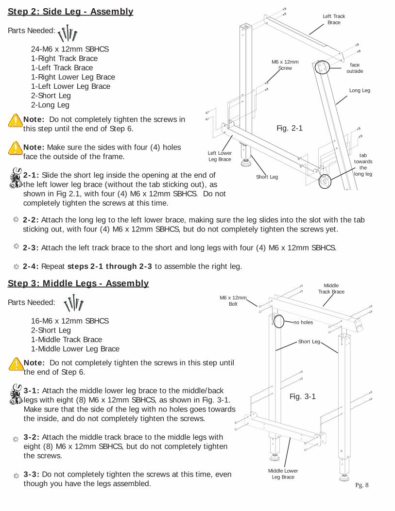
Step 2: Side Leg - Assembly
Parts Needed:
24-M6 x 12mm SBHCS 1-Right Track Brace 1-Left Track Brace 1-Right Lower Leg Brace 1-Left Lower Leg Brace 2-Short Leg 2-Long Leg
Note: Do not completely tighten the screws in this step until the end of Step 6.
Note: Make sure the sides with four (4) holes face the outside of the frame.
2-1: Slide the short leg inside the opening at the end of the left lower leg brace (without the tab sticking out), as shown in Fig 2.1, with four (4) M6 x 12mm SBHCS. Do not completely tighten the screws at this time.
2-2: Attach the long leg to the left lower brace, making sure the leg slides into the slot with the tab sticking out, with four (4) M6 x 12mm SBHCS, but do not completely tighten the screws yet.
2-3: Attach the left track brace to the short and long legs with four (4) M6 x 12mm SBHCS.
2-4: Repeat steps 2-1 through 2-3 to assemble the right leg.
Fig. 2-1
Left Lower Leg Brace
Long Leg
Short Leg
Step 3: Middle Legs - Assembly
Parts Needed:
16-M6 x 12mm SBHCS 2-Short Leg 1-Middle Track Brace 1-Middle Lower Leg Brace
Note: Do not completely tighten the screws in this step until the end of Step 6.
3-1: Attach the middle lower leg brace to the middle/back legs with eight (8) M6 x 12mm SBHCS, as shown in Fig. 3-1. Make sure that the side of the leg with no holes goes towards the inside, and do not completely tighten the screws.
3-2: Attach the middle track brace to the middle legs with eight (8) M6 x 12mm SBHCS, but do not completely tighten the screws.
3-3: Do not completely tighten the screws at this time, even though you have the legs assembled.
Fig. 3-1
Middle Lower Leg Brace
Short Leg
M6 x 12mm Bolt
Middle Track Brace
Left Track Brace
M6 x 12mm Screw face
outside
tab towards
the long leg
no holes

Pg. 9
Fig. 4-2
Step 4: Track Support - Assembly
Parts Needed:
16-M6 x 12mm SBHCS 8-M5 x 10mm SBHCS 1-Left Leg Assembly 1-Right Leg Assembly 1-Middle Leg Assembly 2-Front Track Support 2-Back Track Support 1-Front Track Support Coupler 1-Back Track Support Coupler
4-1: Look at the bottom of each of your front track supports, and locate two holes near one end of the track support.
4-2: Slide the front track support coupler into the end of one track support with the two holes near the end. Tighten two (2) M5 x 10mm SBHCS into the coupler through the track support, as shown in Fig. 4-1.
4-3: Slide the other front track support onto the coupler and tighten two (2) M5 x 10mm SBHCS into the coupler through the track support.
4-4: Follow Step 4-1 through 4-3 for the back track supports and coupler.
Note- The front track support attaches to the diagonal leg.
Fig. 4-1
4-5: Attach the front track support to the left leg assembly with two (2) M6 x 12mm SBHCS, as shown in Fig. 4-2.
4-6: Attach the other end of the front track support to the right leg with two (2) M6 x 12mm SBHCS.
4-7: Tighten four (4) M6 x 12mm SBHCS, through the front track support and into the middle leg.
4-8: Follow Step 4-5 through 4-7 for the back track supports.
M5 x 10mm SBHCS
Front Track Support
Front Track Support Coupler
Back Track Support Coupler
Back Track Support
M6 x 12mm SBHCS
Front Track Support
Back Track Support
M6 x 12mm SBHCS

Pg. 10
Step 5: Track Installation
Parts Needed:
3-60” Crib Tracks* 3-120” King Tracks**
*For Crib setup only.** For King setup only.
5-1: Slide one piece of track into the back track support, as shown in Fig. 5-1.
5-2: Slide two pieces of the track into the front track support.
Fig. 5-1
Step 6: Frame End - Assembly
Parts Needed:
1-Left Frame End 1-Right Frame End 1-Left Frame Corner 1-Right Frame Corner 4-Spacers 4-M6 x 12mm SBHCS 4-M6 x 25mm SBHCS
6-1: Slide a M6 x 25mm SBHCS through both of the bottom holes in the right frame end and then slide a spacer on the end of those screws, as shown in Fig. 6-1.
Fig. 6-1
Fig. 6-2
Track
Spacer
Right Frame End
Right Frame Corner
M6 x 25mm SBHCS
M6 x 12mm SBHCS
6-4: Follow Step 6-1 through 6-3 for the left side.
6-2: Screw those screws into the bottom holes in the right legs.
6-3: Screw two (2) M6 x 12mm SBHCS through the top holes of the right frame end and leg, as show in Fig. 6-2. Do not completely tighten the screws at this time.
6-5: Remove the two screws from the back corner of the right leg, as show in Fig. 6-1.
6-7: Thread the removed screws into the right frame corner and through the back track support into the leg.
6-8: Follow Step 6-5 through 6-7 for the left side. Do not completely tighten the screws.
6-6: Place the right frame corner over the back track support and the right frame end.
Note: Completely tighten all the screws left loose in steps 2, 3, and 6. Make sure you start at one end of the frame and work your way to the other end keeping your track supports lined up as you go.

Pg. 11
Step 7: Shelf Support - Assembly
Parts Needed:
24-M5 x 10mm SBHCS (King) (only 16 for Crib) 4-Shelf Support (King) (only 2 for Crib) 4-Shelf Support Connectors (King)
7-1: Attach the shelf support connectors to the middle lower leg brace with two (2) M5 x 10mm SBHCS each, as shown in Fig. 7-1.
Fig. 7-1
Step 9: Take Up Rail Bracket - Assembly
Parts Needed:
2-Take-Up Rail Mount End
9-1: Slide two (2) M6 x 25mm carriage bolts through the holes in the left frame end from the inside of the frame so the bolts goes through the center slots, as shown in Fig. 9-1.
9-2: Slide the take-up rail mount end onto the two bolts, followed by one plastic spacer. Then tighten a M6 plastic knob onto the end of each bolt.
9-3: Follow steps 9-1 through 9-2 for the right side.
Fig. 9-1
M5 x 10mm SBHCS
Shelf Support Connectors
M5 x 10mm SBHCS
Shelf Support
M6 Plastic Knob
Take Up Rail Bracket
M6 x 25mm Carriage Bolt
Plastic Knob Spacer
Fig. 7-2
7-2: Attach a shelf support to the right lower leg shelf brace with two (2) M5 x 10mm SBHCS and then attach the other side to the shelf support to the shelf support connectors using two (2) M5 x 10mm SBHCS.
7-3: Follow Step 7-2 to attach the last three (3) shelf supports to the frame.
Middle Leg
Step 8: Table Support - Assembly
Parts Needed:
12-M5 x 10mm Countersink Screw **(3 for Crib) 6-Table Support (King) **(3 for Crib)
8-1: Attach all six (6) table supports to the track supports using two (2) M5 x 10mm screw, as shown in Fig. 8-1. Do not completely tighten the screws at this time.
Fig. 8-1
Note: Thescrewsgothroughthetracksupportflangefirstand then screw into the support. The table support end goes underneaththetrack’sflangewiththetapesideup.
Table Supports
M5 x 10mm Countersink
Screw
Tip: It might be easier to attach your shelf support connectors to your shelf supports before you attach them to your frame.

Pg. 12
Step 10: Bungee Brace - Assembly
Parts Needed:
2-M6 x 15mm SBHCS 2-M6 Hex Nuts 1-Right Bungee Clamp Brace 1-Left Bungee Clamp Brace 1-Right Front Rail Mount End 1-Left Front Rail Mount End
10-1: First remove the screw from the top hole and keep the M6 x 15mm SBHCS and hex nut for use in this step. Now slide an M6 x 15mm SBHCS through each hole in the left bungee clamp brace, as shown in Fig. 10-1.
10-2: Slide the screws through the holes in the left front rail mount end.
10-3: Tighten the screws into the nuts.
10-4: Repeat steps 10-1 through 10-3 to complete the right side.
Fig. 10-1
Step 11: Front Rail Mount End - Assembly
Parts Needed:
2-Front Rail Mount End Assemblies
11-1: Slide two (2) M6 x 25mm carriage bolts through the holes in the left frame end so the bolts go through the center slot, as shown in Fig. 11-1.
11-2: Slide the front rail mount end onto the two bolts, follow this with one plastic spacer and then tighten a M6 plastic knob onto the end of each bolt.
Fig. 11-1
Step 12: Shelf - Assembly
Parts Needed:
2-Shelf (King) (only 1 for Crib)
NOTE: To prevent the shelf surface from being attached out of square, begin removing the backing from the tape, starting at one end of the Frame removing it only in one (1) foot sections. Line up the shelf surface with the shelf braces, and pressfirmlyinplacebeforeremovingthenextone(1)footsectionoftapebacking.Repeat this process until the both shelf surfaces are attached.
Fig. 12-1
Left Bungee Clamp Brace
M6 x 15mm SBHCS
M6 Hex Nut
Left Front Rail Mount End
M6 x 25mm Carriage Bolt
Plastic Knob Spacer
Shelf
11-3: Repeat steps 11-1 and 11-2 for the right side.M6 Plastic
Knob

Pg. 13
12-1: Attach the plastic shelf, with the textured surface side UP, to the shelf braces using the pre-installed double sided tape, as shown in Fig. 12-1.
12-2: Repeat Step 12-1 so that both plastic shelf surfaces are attached to the table assembly.
Step 13: Table - Assembly
Parts Needed:
2-Tables (King) (only 1 for Crib)
NOTE: To prevent the table surface from being attached out of square, begin removing the backing from the tape, starting at one end of the Frame removing it only in one (1) foot sections. Line up the table surface withthetablebraces,andpressfirmlyinplacebeforeremovingthenextone (1) foot section of tape backing. Repeat this process until the both table surfaces are attached.
13-1: Attach the plastic table, with the textured surface side UP to the table braces using the pre-installed double sided tape, as shown in Fig. 13-1.
13-2: Repeat Step 13-1 so that both plastic table surfaces are attached to the table assembly.
Fig. 13-1
Step 14: Rail - Assembly
Parts Needed:
24-M5 x 16mm SBHCS 48-M5 x 10mm Screw (none for Crib) 6-2” Rails (King) (only 3 for Crib) 2-1.5” Rail (King) (only 1 for Crib) 4-Rail Couplers (none for Crib) 6-Ratchet Wheels 2-Fourth Rail End Caps
14-1: On one end of four (4) of the 2 inch rails, slide a ratchet assembly inside the rail, as shown in Fig. 14-1. Attach the ratchet assembly to the rail with three (3) M5 x 16mm SBHCS. Tighten the screw in a clockwise manner till they are completely tight.
Fig. 14-1
Table
Ratchet Wheel
M5 x 16mm SBHCS
14-2: On one end of the two (2) 1.5 inch rails, slide a ratchet assembly around the rail. Attach the ratchet assembly to the rail with three (3) M5 x 16mm SBHCS. Tighten the screws in a clockwise manner till they are completely tight.
14-3: On one end of the remaining two (2) 2 inch rails, slide a fourth rail end cap inside the rail, as shown in Fig. 14-2. Attach the fourth rail end cap to the rail with three (3) M5 x 16mm SBHCS. Tighten the screws in a clockwise manner till they are completely tight.
14-4: Now take one of the 1.5 inch rails and slide the 1.5 inch rail coupler in the rail so you can see the coupler holes through the rail holes.

Pg. 14
14-11: Attach the coupler to the rails using six (6) M5 x 10mm SBHCS. Tighten all the screws in a clockwise manner until they are all tight.
14-12: Slide the last 2 inch rails with the fourth rail end cap attached over the coupler and attach the rail to the coupler by using six (6) M5 x 10mm SBHCS.
14-13: Now check all the screws on all the rails to make sure they are tight.
Fig. 14-3
M5 x 10mm SBHCS
Coupler
Fourth Rail End Cap
M5 x 16mm SBHCS
14-5: Attach the coupler to the rails using six (6) M5 x 10mm SBHCS, as shown in Fig. 14-3. Tighten all the screws in a clockwise manner until they are all tight.
14-6: Slide the other 1.5 inch rail over the coupler and attach the rail to the coupler by using six (6) M5 x 10mm SBHCS.
14-7: Now take two of the 2 inch rails with the ratchet wheels attached and slide a 2 inch rail coupler in the rail so you can see the coupler holes through the rail holes.
14-8: Attach the coupler to the rails using six (6) M5 x 10mm SBHCS. Tighten all the screws in a clockwise manner until they are all tight. 14-9: Slide the other 2 inch rails with the ratchet wheels attached over the coupler and attach the rail to the coupler by using six (6) M5 x 10mm SBHCS.
14-10: Now take one of the remaining 2 inch rails with the fourth rail end cap attached and slide a 2 inch rail coupler in the rail so you can see the coupler holes through the rail holes.
Fig. 14-2
Step 15: Rail to Frame - Assembly
Parts Needed:
4-Rail Assembly 4-M6 x 15mm SBHCS 2-Ratchet Wheel Holder 2-4th Rail Insert Washer
M6 x 15mm SBHCS
Ratchet Wheel Holder
15-2: Screw two (2) of the M6 x 15mm SBHCS into the ratchet wheel holder. Follow the same step for the other side of the rail.
Fig. 15-1
2” Rail
M6 Hex Nut(Preinstalled)15-1: Take one of the 2 inch rails (with ratchet
wheels) and slide it up into the front rail bracket till it clicks into place. Then place the ratchet wheel holder in between the ratchet wheel and rail end as shown in Fig. 15-1.

Pg. 15
Step 16: Top Carriage - Assembly
Parts Needed:
4-M6 x 12mm SBHCS 2-M6 x 15mm SBHCS 1-Handle Cross Brace 1-Right Handle 1-Left Handle 1-Carriage Top Plate
16-1: Attach the right handle to the carriage top plate with two (2) M6 x 15mm SBHCS, as shown in Fig. 16-1.
16-2: Attach the left handle in the same manner as the right.
16-3: Place the handle cross brace on the front of the two handles, as shown in Fig. 16-2.
16-4: Insert a screw through the top of each of the two holes in the handle brace and then handles.
16-5: Tighten the screws into the preinstalled inserts.
16-6: Follow Step 16-3 through 16-5 for the other side.
Fig. 16-1
Fig. 16-2
M6 x 12mm SBHCS
Right Handle
M6 x 15mm SBHCS
Handle Cross Brace
15-4: Take the 1.5 inch rail and slide each side down into the take-up rail bracket and put some pressure on it till it clicks into place.
15-5: Take the 2 inch rail (with a ratchet wheel) and slide each side down into the front rail bracket and put some pressure on it till it clicks into place.
15-6: Look in the tab that is sticking out on the angled leg and insert the 4th rail insert washer, by pushing it into the hole, from the inside, in the tab.
15-7: Take the 2 inch rail (with fourth rail end caps) and pop it into place, as shown in Fig. 15-2.
Fig. 15-2
4th Rail
4th Rail Insert Washer

Pg. 16
Step 17: Bottom Carriage - Assembly
Parts Needed:
2-M6 x 20mm SBHCS 2-M6 Nylock Nut 2-Carriage Bearing 1-Bottom Plate 1-Bottom Plate Surface
17-1: Turn your bottom carriage over so the bearing side is up.
17-2: Slide a bolt through the carraige wheel mount.
17-3: Slide the carriage bearing over the screw on thebottomplateflangeandthentightenanylocknutonto the end of the screw, as shown in Fig. 17-1.
17-4: Follow Step 17-2 through 17-3 for the other wheel.
17-5: Attach the bottom plate surface, (with the textured surface side UP) to the bottom carriage using the pre-installed double sided tape, as shown in Fig. 17-2.
M6 Nylock Nut
Carriage Bearing
M6 x 20mm SBHCS
Step 18: Carriage to Frame- Assembly
Parts Needed:
1-Top Plate 1-Bottom Plate
Single Wheel
Double Wheel
18-1: Place the bottom plate on your frame, making sure the dual bearing side goes on the front track support (The front track support is attatched to the slanted leg).
18-2: Place the top carriage on the bottom carriage with the handle cross brace towards the front of the frame.
Fig. 17-1
Fig. 17-2
Fig. 18-1
Front of Frame

Pg. 17
Congratulations! You have completed the assembly of your Quilting Frame.
All that remains is to install your fabric and begin quilting! (You’ll notice you still have Bungee Clamps leftover. These will be assembled in conjunction with your fabric installation).
With the Grace, specially designed Fabri-Fast rails, installing your fabric is easier on this Frame than on any other frame. Each rail has a Fabri-Fast slot and accompanying tubing. These work together to make your fabric installation much easier and faster than using tape, tacks, or Velcro®.
Before you begin, please locate the plastic Fabri-Fast tool included in your shipment.
We recommend you begin with practice material allowing you to experiment with machine settings and stroke techniques.
NOTE: As you cut your fabric layers, we recommend making the quilt backing about 6-8” longer and 2-4” wider than your top. This will allow for a little give in the backing, especially if using thicker batting.
Quilting Frame Fabric Installation
Rail Rotation: It is important that each rail rotates the correct direction to apply tension to your quilt layers correctly. Light tension is applied to your quilt fabric to remove wrinkles, and to allow the fabric to be sewn together consistently throughout the entire quilt. The Ratchet Rail ends allow you to limit the direction that each rail rotates. The ratchet can also be set to a neutral position by pulling the knob up and twisting it.
Installing Fabric Layers onto the Rails (Preview): Center your cloth lengthwise along the rail. Using Grace’s Fabri-FastTM System, take a piece of plastic tubing (cut to the appropriate length), and, holding your fabric to the slot (lining up the edge), press the tubing over the fabric and into the slot. Use the Fabri-Fast tool to press the rest of the tube and fabric in quickly and easily.
Methods of Installation: 1: The recommended method for installing fabric onto the rails is to apply your fabric layers directly to the rails. 2: You may also make and use Cloth Leaders.
OVERVIEW: This is an outline to show which fabric layer goes onto each rail, and the direction that each rail should rotate.
Step 1: Install Batting to Batting rail and roll up.Step 2: Install Quilt Top to the Quilt Top rail and roll up.Step 3: Install Backing to Backing rail and roll up.Step 4: Attach Quilt Layers to Take-Up rail.

Pg. 18
Step 1: Batting
NOTE: A light, bonded batting is recommended.
1-1: Center the batting on the batting rail and attach one end of the batting using the fabri-fast tubing. (NOTE: Fabri-Fast tubing will work with most batting, however, if the batting is too thick to squeeze into the slot, you may tape the batting to the rail to keep it in place).
1-2: Roll the batting onto the rail. The direction that you roll the batting onto the rail doesn’t matter. The important thing to watch when rolling batting onto the rail is that the batting isn’t stretched(See Fig. 1-1).
Step 2: Quilt Top to Quilt Top Rail
2-1: Determine which end of your quilt will be the front.
2-2: Placethequilttopontothetablesurfacewithitsfinishedsidefacingup.Lineupthecenterofyour fabric layer with the center of the quilt top Rail. Attach the back edge of your quilt top to the quilt toprail.Thisistobedonewiththefinishedsideofthefabricfacingup.Donotstretchorpullthefabricduring this process. Let it lay as naturally as possible.
2-3: Roll your quilt top onto the Quilt Top Rail completely. Again, be sure the fabric stays lined up. Smooth out any wrinkles as you roll by brushing the fabric from the center out, being very careful not to stretch or pull the fabric excessively.
Take-Up Rail
Quilt Backing
Backing Rail
Quilt TopQuilt Top Rail
Batting
Batting Rail
Fig. 1-1
Step 3: Quilt backing to Backing rail
3-1: To begin, determine which will be the front and back edges of your quilt backing. (Your quilt can’t exceed (110” wide) the maximum quilt width of your Quilting Frame. Your quilt’s length is not limited)
NOTE:Ifyourbackingismadeupofmorethanonepieceoffabric,cutyourselvedgesoffandflattenout the seams with an iron to allow the backing the proper give it needs.
3-2: Place your quilt backing onto the table surface good side down. Line up the center of your fabric layerwiththecenteroftheBackingRail.Attachthebackingwithitsfinishedsideofthefabricfacingthe rail. Do not stretch or pull the fabric during this process. Let it lie as naturally as possible.

Pg. 19
3-3: Roll your backing onto the backing rail completely. Watch to make sure the fabric stays lined up. Smooth out any wrinkles as you roll by brushing the fabric from the center out. However, be very careful not to stretch or pull the fabric excessively.
NOTE: It is important that you roll the rail the proper direction so the fabric rolls onto the quilt top rail the right way (If the rail always rotates the correct direction, as indicated in Fig. 1-1 you will avoid potential problems with the quilt fabric).
Backing RailQuilt Top Rail
Batting Rail
Take-Up Rail
Batting
Quilt Top
Fig. 3-3
Quilt Backing
Take-Up Rail
Backing Rail
Quilt Top Rail
Batting Rail
Fig. 2-1
Step 4: Attaching Quilt Layers to the Take-Up Rail.
4-1: Put the Take-Up Rails Ratchet into position, to ensure that it always rotates the correct direction.
4-2: Take the end of the quilt backing and attach it to the take-up rail with the fabri-fast tubing, be careful to not stretch your fabric. Roll the Backing Rail to apply just enough tension to the Backing fabric. The fabric should be loose, but not sagging.
4-3: Next, bring your Batting up in between the Quilt Top Rail and Backing Rail and drape over the Backing. Lay it along the edge of the Take-Up Rail (See Fig. 3-3).
4-4: Bring the edge of the Quilt Top up over the Backing and Batting and lay it over the batting along the Take-Up Rail. Pin your Top and Batting to the Backing, in a straight line along the edge of the Take-up Rail. You may also baste the edge with your sewing machine.

Pg. 20
You are now ready to sew your desired patterns onto your quilt.
Rolling your fabric
When you have completed your work area and are ready to roll to the next, simply switch the Quilt Top, and Backing Ratchets into the unlocked position, allowing them to roll freely. Roll the Take-Up Rail forward, rolling the sewn quilt area onto that rail. After you have advanced your quilt to the next location, move each Rail’s Ratchet lever to it’s pre-determined position, and re-apply just enough tension to hold the fabric up without sagging, and without stretching the fabric.
TIP! As you roll the quilt forward, the quilt will accumulate on the Take-Up Rail. Raise the Take-Up Rail Bracket as needed, so that the bottom of the rolled up fabric stays about 1/16” above the sewing machine base. Failing to do so will cause your Carriage Assembly to roll less smoothly.
Turning Quilt Around (This will enable you to quilt the entire quilt surface.)
Step 1: Begin pin basting your quilt when the quilt rolled up onto the Take-Up Rail is larger than desired. Pin baste all of the remaining un-quilted material.
Step 2: Detach the individual layers of fabric from their rails (Backing, Top, and Batting) and roll them up onto the Take-Up Rail. (Keep The quilt attached to the Take-Up Rail.)
Step 3: Remove the Backing Rail. Remember to support the rail to prevent the Rail Ends from beingbroken.Temporarilyplacetherailonthefloorinfrontofyourquiltingframe.(Werecommendhaving someone help you with this step and also with step 4.)
Step 4: Remove the Take-Up Rail (with quilt rolled onto it) and put it into the highest notch in the Fabric Layers Rail Brackets (the Backing Rail Location), making it the New Backing Rail. Now put the other rail in the Take-Up Rail location, making it the New Take-Up Rail. Step 5: Attach the (quilt) two layers of fabric, and the batting to the New Take-Up Rail, using the Fabri-Fast Tubing. Step 6: Roll the quilt off of the New Backing Rail, onto the New Take-Up Rail. Place the New Take-Up Rail’s ratchet into the locked position.
Step 7: Place the ratchet in neutral and roll the quilt back onto the other rail with its ratchet is in the locked position until you can see the area where you left off quilting. Step 8: Place the ratchet on the New Take-Up Rail in the locked position, add a little tension to your fabric and you are ready to begin quilting again.
NOTE: As you advance to the next area roll the fabric off of the Take-Up Rail and out of the throat of thesewingmachineandyourfinishedquiltwillnowberolledupontotheBackingRailatthefrontoftheframe rather than onto the Take-Up Rail.

Pg. 21
Making Cloth Leaders
1: First, select your cloth leader material. We recommend using a good quality muslin or similar fabric that has a good thread count. Be aware, however, that if the fabric is too thick, it may prove more difficultgettingitinstalledintotherailslot.
2: Surge or hem your cloth leaders on all sides.
3: Make cloth leaders in the following widths. (The recommended length is 105”, this length will accommodate any width of quilt that can be made on your Quilting Frame.)
4: Make a dashed line along the length of your leader about ½” in from the edge with a pen or marker. You will use this as a guide to help you insert your leader into the slot in straight line. (OPTIONAL: For a straighter cloth leader installation, some may consider it easier to make a hem and then push the tubing into the hem before installing it into the slot. If you wish to do this, create a hem on one end of each leader by folding over the fabric one inch (1”), and, using your foot pedal as a guide, stitching the fabric together 3/4” from the fold. This will leave about ¼” of fabric beyond the stitching. Leave the edges open on both ends. You may then slide your tubing into the hem, Fig. CL1-1).
5: Mark each cloth leader at the center (length-wise).
6: Mark (or baste) a straight line about ½” in from the opposite (non-hemed, or non-dashed) end of the leader. This will be the line to which you attach your fabric layer.
7: Center your cloth leader lengthwise along the rail. Using Grace’s Fabri-FastTM System, take a piece of
plastic tubing (cut to the appropriate length), and, holding your cloth leader to the slot (lining up the dashed line), press the tubing over the leader and into the slot. Use the Fabri-Fast tool to press the rest of the tube and fabric in quickly and easily. (If you have made a hem, line up this hem w/ tubing over the slot and press it into the slot using the Fabri-Fast tool.
8: With Cloth Leaders in place, pin your Quilt Fabric to the Leaders, rather than attaching it directly to the Rails.
5"13
"20
1/2
"
Take Up Leader
Backing Leader
Top Fabric Leader
3/4" Casing
3/4" Casing
3/4" Casing

Pg. 22
Bungee Clamp InstallationThere are 4 Bungee Clamps provided with your Quilting Frame. The Bungee Clamps allow you to easily add side tension to your quilt fabric. Clip your Bungee Clamps to the quilt fabric, then insert the loose Bungee end through the Bungee Holder, looping it back into the Bungee Holder. Apply some tension to the Bungee then slide the bungee that is in the crescent moon side of the bungee holder toward either tapered side to grip the bungee in place.
There are many optional accessories available for your Quilting frame.
Lamp Holder Accessory: Your Quilting Frame was shipped with Lamp Brackets, as well as the hardware required to attach the brackets. The Lamp Brackets are easily attached to the Handle Braces. Lamps, and other accessories can be attached to the Lamp Brackets. You can purchase a Lamp from the Grace Company web site, www.graceframe.com, or by calling Your Grace Company Distributor.
Optional Accessories
Sewing Tips•Becarefulnottosewtooclosetotheedge,topreventhittingyourBungeeClamps,orrunningofftheedge of the quilt. Also, if you are using side leaders, avoid accidently stitching the leaders to your quilt.
•IfyourquiltwillfitontoyourframeLength-wiseattachyourquilt’sfabrictotherailsalongit’slength.You will have to roll the quilt less often, since your work surface will be as large as possible. Also, the quilt will not be as fat under the arm of the machine when you get to the end.
•Youwillneed4-5bobbinstoquiltasmallsizedquilt(lessthanaqueen).
•Makesuretoturnoffyoursewingmachineanytimeyouleaveyourquiltingroom,especiallyifyouareusing the peddle pushing mechanism. If the mechanism pushes the pedal at all it may cause your sewing machine and peddle to get very hot.
•KeepingthefabricontheTake-UpRailtouchingthebedofthesewingmachine,insteadofabovethebed yields better results. If the fabric is too high off the bed, bouncing will occur.
•Whenrollingthequilt,pullthebattingalittletoeachsidetomakesurethatitisnotbunching.Afterrolling and tightening all the rollers, check under the quilt to see that the back is smooth.

Pg. 23
Grace Speed ControlThe Grace Speed Control is designed to work with the sewing machine that has been provided with your Quilting Frame.
Connecting to your sewing machine:
For Technical Assistance please contact:
The Grace Company1-800-264-0644
Speed Control-Allows you to set your machine to desired stitch-speed ranging from slow to full speed.
Pulse Button-Machine stops when you release, or use for single stitch.
On/Off-Press for on, press again for off
Front Panel
Jack Plug-In
(To Sewing Machine)
(To Speed Control Jack)
Sewing Machine Plug-In
Jack Plug-In

Pg. 24
1. CAUTION: Use of controls, adjustments, or performance of procedures other than given in USER MANUAL may result in hazardous laser light exposure.2. This product is safe to use in normal operations as described in these instructions. AVOID DIRECT EYE EXPOSURE. DO NOT LOOK DIRECTLY INTO THE LASER EMITTER.
Specifications:Power: Class IIWavelength: 650nmOutput Power: 1mWBattery Type: 2 AABattery Life: 150 Continuous hoursWeight: 31.2g Without BatteriesDimensions: 6.929” L X 1.533” WColor: Blue
TheGraceCompanycertifiesthattheGracieLasercomplieswiththe government FDA regulation 21CFR 1040.10 and 1040.11.
The Gracie Laser User Manual
SAFETY PRECAUTIONS
ACTUAL SIZE
CAUTIONLASER RADIATION-
LASER DIODEWavelength: 650nM
Max Output Power: <1mWThis device complies with
21 CFR. Chapter I, Subchapter JCLASS II LASER PRODUCT
ZHONGSHAN CITY NEWWISH METAL & ELECTRONICALGUANGDONG PROVINCE, CHINA
Manufactured date: JANUARY 2006
DO NOT STARE INTO BEAM
CAUTIONLASER RADIATION-
LASER DIODEWavelength: 650nM
Max Output Power: <1mWThis device complies with
21 CFR. Chapter I, Subchapter JCLASS II LASER PRODUCT
ZHONGSHAN CITY NEWWISH METAL & ELECTRONICALGUANGDONG PROVINCE, CHINA
Manufactured date: JANUARY 2006
DO NOT STARE INTO BEAM
Warning Labels are located on the product, as shown:
Parts List
(on reverse side)
Laser Pointer (1)
M6 Knob (2) M6 x 60mm Hex Head bolt (1)
M6 x 45mm Hex Head bolt (1)
Battery Compartment Cover
On/Off Button
Laser Emitter
(+) End of AA Battery
(+) End of AA Battery
Hex Swivel Head (1)
Main Swivel Attatchment (1)
Battery Installation: Use the battery compartment opening tab to remove the battery cover. Batteries are inserted with their possitive pole (+) opposite each other. (Illustration shown)
Battery Compartment Opening Tab

Pg. 25
Laser Assembly
Carriage Installation:Step 1: Insert the M6x45mm Hex Head Bolt through the Laser Pointer Assembly.
Step 2: Insert the M6x45mm Hex Head Bolt through an available 1/4” hole in the Top Platform. (If none of the available holes suit your needs, drill a 1/4” hole in the desired location.)
NOTE: The Laser Pointer may be mounted on either side of the Top Platform, and is easily moved from one side of the Top Platform to the other.
Step 3: Secure the Laser Assembly and bolt to the Top Platform with the M6 Plastic Knob.
M6 x 60mm Hex Head BoltHex Swivel Head
Main Swivel Attatchment
Laser Pointer
M6 Knob
M6 x 45mm Hex Head Bolt
M6 Knob
Assembly Steps: Step 1: Insert the M6x60mm Hex Head Bolt through the Hex Swivel Head with the rounded portion up.Step 2: Continue by pushing the bolt through the Main Swivel Attachment and through the Laser Pointer.Step 3: Tighten the M6 Knob onto the of of the M6x60mm Hex Head Bolt.