QUIETFLOW TWIN SQT - Amazon Web Services
12
These instructions must be read fully before commencing installation. QUIETFLOW TWIN SQT Installation & Maintenance
Transcript of QUIETFLOW TWIN SQT - Amazon Web Services

These instructions must be read fully before commencing installation.
QUIETFLOW TWIN SQT Installation & Maintenance

Tel 01384 275800 Fax 01384 275810 Email [email protected] Website eltafans.com2
Installation Instructions
QUIETFLOW TWIN SQT
1.0 General1.1 It is important these Installation and Maintenance Instructions are fully adhered to.1.2 Full details of the unit supplied are shown on the product nameplate. If in doubt about any detail contact Elta Fans Ltd or its agents for clarification.1.3 All electrical installation must be carried out by suitably qualified and competent personnel in accordance with all current statutory requirements.1.4 These instructions cover only the Elta Fans Ltd product and do not include the supply or installation of any safety equipment that may be required e.g. adequate guarding or protection from rotating parts and proper electrical isolation.1.5 Any declarations made by Elta Fans Ltd about product installation and safety, are dependant on the fan equipment being used within installations which themselves meet the requirements of the relevant Standards and Directives of your region.1.6 The fan is designed for use in an ambient temperature of -20°C up to a maximum of +60°C and up to 95% relative humidity. The fan is not suitable for corrosive or explosive atmospheres.1.7 The installer should provide easy access to the fan to facilitate future maintenance.1.8 The installer should ensure the fan is adequately supported.1.9 This product is not intended for use by persons (including children) with reduced physical, sensory or mental capabilities, or lack of experience and knowledge, unless they have been given supervision or instruction concerning use of the product by a person responsible for their safety. Children should be supervised to ensure that they do not play with the product.1.10 At end-of-life, the unit must be disposed of in an environmentally friendly manner by suitably qualified and competent personnel ina ccordance with the requirements of applicable Standards and Directives.
2.0 Installation
WARNING – The fan must be isolated from the power supply during installation and maintenance. The fan must be earthed in accordance with the local regulations.
2.1 Upon receipt, the fan equipment should be visually inspected to check for any damage. Ensure that the impeller is free to rotate.2.2 If there are any queries concerning the fan equipment, Elta Fans Ltd should be contacted prior to the installation.2.3 The fan must be securely mounted in the desired position to suit the application. The fan can be mounted horizontally only.2.4 Check the details on the motor rating plate to ensure that the correct power supply (voltage, frequency and phase) is available. An incorrect power supply will lead to permanent damage to the fan motor.2.5 Refer to the appropriate wiring diagram. Ensure that all earth connections are made.2.6 Means for electrical disconnection must be incorporated in the wiring installation in accordance with the relevant wiring and electrical regulations.2.7 Precaution must be taken to locate the exhaust discharge terminal so as to avoid the backflow of gases into the room from the open flue of gas or other fuel burning appliances.
EC
Please note: This is an estimated adjustment guide
149-CD-POT
The 149-CD-POT is a commissiong device designed to be used with our EC range of fans.
This device will be as standard with our box fan range from May 2018.
The device will allow the for the installer to set the maximum operating speed of the fan that it isconnected to.
The installer or commissioning engineer can adjust the fan speed using the potentiometer built onto the149-CD-POT board. This potentionmeter can either be used for single speed adjustment or to set amaximum speed for the fan to operate at when an external control source is used.
If external speed control is required, the jumper connection next to the potentionmeter on the boardwould need to be removed, the installer can then connect to ST1 (using the diagram provided).
When an external speed control is �tted, the maximum speed setting available to the external control islimited by the potentiometer setting of the commissioning device.
10/07/2018MK-149-CD-POT Issue: Saved Date:A
Level / Speed OHMS (Ω)
10 10 (Ω)
9 9 (Ω)
8 8 (Ω)
7 7 (Ω)
6 6 (Ω)
5 5 (Ω)
4 4 (Ω)
3 3 (Ω)
2 1.5 (Ω)
1 500 (Ω)
0 1 (Ω)149-CD-POT

Elta Fans Limited has a policy of continuous product development and improvement and therefore reserves the right to supply products which may differ from those illustrated and described in this publication. Confirmation of dimensions and data will be supplied on request. 3
EC
3.0 Start Up3.1 Before power is supplied to the unit, check that the wiring is correct as per the fan connection diagram.3.2 At initial start-up, check that impeller rotation and airflow direction is correct.3.3 Check that the motor amperage drawn does not exceed the nameplate rating.
4.0 Fan Maintenance4.1 Inspection of the fan at least once every 12 months is recommended to ensure that the motor, fan blades, and supporting guards, are clean. Any build up of dust and deposits on the blades or guards should be removed using a non-abrasive cleaner.4.2 All fastenings should be checked for tightness. In addition, all rotating items should be checked.4.3 Bearings are of the ‘sealed for life’ type and will not need a detailed inspection.
WARNING - The EC fan has internal electronic overload protection and the AC fan is fitted with an auto-reset thermal cut-out which switches the fan off in the event of a fault condition. Once the motor cools down the fan may start unexpectedly. Only a suitably qualified and competent person may carry out maintenance after the electrical supply has been isolated.
Installation Instructions
QUIETFLOW TWIN SQT
All wiring and control equipment must comply to the latest IEE regulations, in particular part 552-01-02/03. 149-CD-POT Issue A: 10.07.2018Check the individual product accessories table for fan controller compatibility.
Please note: This is an estimated adjustment guide
149-CD-POT The 149-CD-POT is a commissiong device designed to be used with our EC range of fans. This device will be as standard with our box fan range from May 2018. The device will allow the for the installer to set the maximum operating speed of the fan that it is connected to. The installer or commissioning engineer can adjust the fan speed using the potentiometer built onto the 149-CD-POT board. This potentionmeter can either be used for single speed adjustment or to set a maximum speed for the fan to operate at when an external control source is used. If external speed control is required, the jumper connection next to the potentionmeter on the board would need to be removed, the installer can then connect to ST1 (using the diagram provided). When an external speed control is fitted, the maximum speed setting available to the external control is limited by the potentiometer setting of the commissioning device.
Elta Fans Limited has a policy of continuous product development and improvement and therefore reserves the right to supply products which may differ from those illustrated and described in this publication. Confirmation of dimensions and data will be supplied on request. 3
EC
3.0 Start Up3.1 Before power is supplied to the unit, check that the wiring is correct as per the fan connection diagram.3.2 At initial start-up, check that impeller rotation and airflow direction is correct.3.3 Check that the motor amperage drawn does not exceed the nameplate rating.
4.0 Fan Maintenance4.1 Inspection of the fan at least once every 12 months is recommended to ensure that the motor, fan blades, and supporting guards, are clean. Any build up of dust and deposits on the blades or guards should be removed using a non-abrasive cleaner.4.2 All fastenings should be checked for tightness. In addition, all rotating items should be checked.4.3 Bearings are of the ‘sealed for life’ type and will not need a detailed inspection.
WARNING - The EC fan has internal electronic overload protection and the AC fan is fitted with an auto-reset thermal cut-out which switches the fan off in the event of a fault condition. Once the motor cools down the fan may start unexpectedly. Only a suitably qualified and competent person may carry out maintenance after the electrical supply has been isolated.
Installation Instructions
QUIETFLOW TWIN SQT
GND 10V E1
MIN MAX
E1GND
ST1
ST2
ST2
E110VGND
MAXMIN
ST1
GND E1
THE ABOVE DIAGRAM SHOWS "ST2".
"ST2" CONNECTIONS ARE FACTORY FITTED.
GND = COMMON•10V = 10VDC INPUT•E1 = 0-10VDC OUTPUT•
YOU CAN DETERMINE THE CURRENT VDC OUTPUT BYDISCONNECTING POWER TO THE UNIT, SETTING AMULTIMETER TO OHMS (Ω) AND PLACING THE TEST PROBESBETWEEN GND AND E1
PLEASE USE THE ESTIMATED ADJUSTMENT GUIDE FOR REFERENCE
THIS IS THE INTERNAL POTENTIOMETERTHIS POTENTIOMETER CAN BE ADJUSTED FOR SINGLE SPEED SETTING OR MAX SPEED SELECTION
THIS LINK/JUMPER SHOULD BE REMOVEDWHEN USING AN EXTERNAL POTENTIOMETEROR EXTERNAL CONTROL SIGNAL CONNECTEDTO "ST1"
THE ABOVE DIAGRAM SHOWS "ST1".
"ST1" CONNECTIONS ARE CLASSED AS"CUSTOMER/USER CONNECTIONS".
GND = COMMON•+ = VDC OUTPUT AS SET BY•
INTERNAL POTENTIOMETERE1 = 0-10VDC INPUT•
149-CD-POT
10/07/2018MK-149-CD-POT Issue: Saved Date:A
All wiring and control equipment must comply to the latest IEE regulations, in particular part 552-01-02/03. 149-CD-POT Issue A: 10.07.2018Check the individual product accessories table for fan controller compatibility.
Please note: This is an estimated adjustment guide
149-CD-POT The 149-CD-POT is a commissiong device designed to be used with our EC range of fans. This device will be as standard with our box fan range from May 2018. The device will allow the for the installer to set the maximum operating speed of the fan that it is connected to. The installer or commissioning engineer can adjust the fan speed using the potentiometer built onto the 149-CD-POT board. This potentionmeter can either be used for single speed adjustment or to set a maximum speed for the fan to operate at when an external control source is used. If external speed control is required, the jumper connection next to the potentionmeter on the board would need to be removed, the installer can then connect to ST1 (using the diagram provided). When an external speed control is fitted, the maximum speed setting available to the external control is limited by the potentiometer setting of the commissioning device.

Tel 01384 275800 Fax 01384 275810 Email [email protected] Website eltafans.com4
Table 1: Operational Maintenance
Activity Frequency
Inspect AV mounts for Corrosion or “Sag” 6 months
Check earth bonding 6 months
Dampers check rubber stops and grease (lithium based) pivot points, by removing plastic caps Yearly
Check fixings tightness and conditions of brass track and rivets 26,000 hours / 3 years
Inspect and clean impeller 26,000 hours / 3 years
Remove dirt from motor cooling fins 26,000 hours / 3 years
Check operation of anti-condensation heaters 26,000 hours / 3 years
Check for even tip clearance between impeller and casing – For ATEX 10% of motor shaft diameter with 2mm minimum and 13mm maximum. 26,000 hours / 3 years
Check motor Amps 26,000 hours / 3 years
Any corrosion - treat with suitable chemicals 26,000 hours / 3 years
Check casing seals 26,000 hours / 3 years
Table 2: Terminal Box Maintenance
Activity Frequency
Check that lid seal is in place and not damaged Each time the enclosure is opened
Check that lid fixing screws are in place and secured Each time the enclosure is closed
Check that the mounting bolts are tight and free from corrosion Annually
Check security of all cable glands Annually
Check that all screw clamps terminals are secure Annually and each time enclosure is opened
Check enclosure for damage Annually
5.0 Storage5.1 If the fan is not to be used immediately then it should be stored in a clean, dry, vibration free and lockable location.5.2 The impeller must be spun by hand (ensuring that it does not come to rest in the same position) on a monthly basis to prevent hardening of the grease and possible damage to the bearings.5.3 All items to be stored on pallets that afford adequate protection from damage, dust and high humidity.5.4 If storage periods of longer than 1 month are anticipated then Elta (or their Agent) should be contacted prior to storage taking place, to ensure the storage area provisions will not be detrimental to the well being of Elta products.
6.0 Guarantee Elta Fans Ltd will, free of charge, within a period of 1 year from the date of dIspatch from their works, repair or at its option replace any goods which are proved to have defects as a result of defective materials or workmanship. The goods MUST be returned to Elta Fans Ltd carriage paid for examination.
Installation Instructions
QUIETFLOW TWIN SQT
Elta Fans Limited has a policy of continuous product development and improvement and therefore reserves the right to supply products which may differ from those illustrated and described in this publication. Confirmation of dimensions and data will be supplied on request. 5
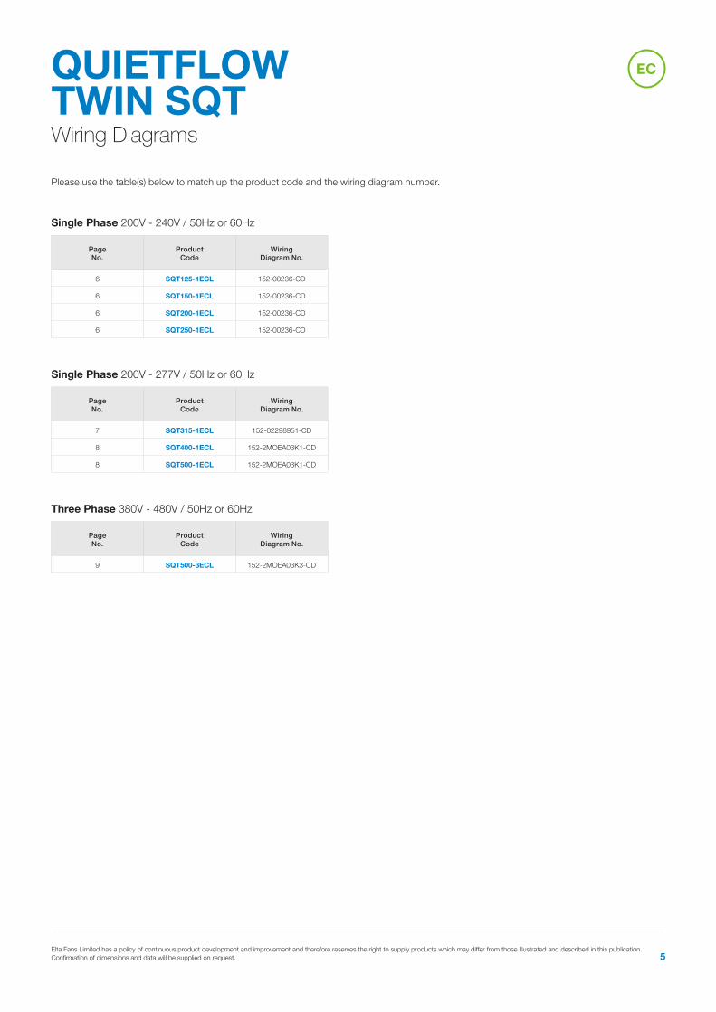
Single Phase 200V - 240V / 50Hz or 60Hz
Single Phase 200V - 277V / 50Hz or 60Hz
Three Phase 380V - 480V / 50Hz or 60Hz
PageNo.
Product Code
Wiring Diagram No.
6 SQT125-1ECL 152-00236-CD
6 SQT150-1ECL 152-00236-CD
6 SQT200-1ECL 152-00236-CD
6 SQT250-1ECL 152-00236-CD
PageNo.
Product Code
Wiring Diagram No.
7 SQT315-1ECL 152-02298951-CD
8 SQT400-1ECL 152-2MOEA03K1-CD
8 SQT500-1ECL 152-2MOEA03K1-CD
PageNo.
Product Code
Wiring Diagram No.
9 SQT500-3ECL 152-2MOEA03K3-CD
Wiring Diagrams
QUIETFLOW TWIN SQTPlease use the table(s) below to match up the product code and the wiring diagram number.
EC
Tel 01384 275800 Fax 01384 275810 Email [email protected] Website eltafans.com6
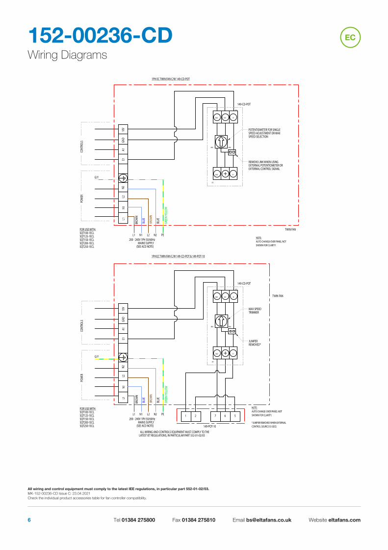
Wiring Diagrams152-00236-CD
ALL WIRING AND CONTROLS EQUIPMENT MUST COMPLY TO THELATEST IET REGULATIONS, IN PARTICULAR PART 552-01-02/03
FOR USE WITH:SQT100-1ECLSQT125-1ECLSQT150-1ECLSQT200-1ECLSQT250-1ECL
G/Y
PEN2N1 L2L1
1PH EC TWIN FAN C/W 149-CD-POT
L2N2
TWIN FAN
BLUE
BROW
N
GREE
N/YE
LLOW
GND 10V E1
MIN MAX
E1GND
ST1
ST2
149-CD-POT
A1GN
D10
VE1
N1L1
BROW
N
BLUE
POW
ER
POTENTIOMETER FOR SINGLESPEED ADJUSTMENT OR MAXSPEED SELECTION
REMOVE LINK WHEN USINGEXTERNAL POTENTIOMETER OREXTERNAL CONTROL SIGNAL
NOTE:AUTO CHANGE-OVER PANEL NOTSHOWN FOR CLARITY.
200 - 240V 1PH 50/60HzMAINS SUPPLY
(SEE ACO NOTE)
CONT
ROLS
MAX
MAX SPEEDTRIMMER
JUMPERREMOVED*
200 - 240V 1PH 50/60HzMAINS SUPPLY
(SEE ACO NOTE)
FOR USE WITH:SQT100-1ECLSQT125-1ECLSQT150-1ECLSQT200-1ECLSQT250-1ECL
CONT
ROLS
POW
ER
NOTE:AUTO CHANGE-OVER PANEL NOTSHOWN FOR CLARITY.
*JUMPER REMOVED WHEN EXTERNALCONTROL SOURCE IS USED.
BLUE
BROW
N
L1N1
E110
VGN
DA1
149-CD-POT
ST2
ST1
GND E1
MIN
E110VGND
2 7 6 5
149-POT-10
1
GREE
N/YE
LLOW
BROW
N
BLUE
TWIN FAN
N2L2
1PH EC TWIN FAN C/W 149-CD-POT & 149-POT-10
L1 L2N1 N2 PE
G/Y
DIMENSIONS ARE IN mm UNLESS STATED OTHERWISE
C
EC
All wiring and control equipment must comply to the latest IEE regulations, in particular part 552-01-02/03. MK-152-00236-CD Issue C: 23.04.2021Check the individual product accessories table for fan controller compatibility.

Elta Fans Limited has a policy of continuous product development and improvement and therefore reserves the right to supply products which may differ from those illustrated and described in this publication. Confirmation of dimensions and data will be supplied on request. 7
Wiring Diagrams152-02298951-CD
CONT
ROLS
200 - 277V 1PH 50/60HzMAINS SUPPLY
(SEE ACO NOTE)
FOR USE WITH:SQT315-1ECLSTDR315-1EC
NOTE:AUTO CHANGE-OVER PANEL NOTSHOWN FOR CLARITY.
*JUMPER REMOVED WHEN EXTERNALCONTROL SOURCE IS USED.
WAGO BLOCK USED.
JUMPERREMOVED*
MAX SPEEDTRIMMER
POW
ER
BLUE
BROW
N
L1N1
E110
VGN
DD1
A1
149-CD-POT
ST2
ST1
GND E1
MAXMIN
E110VGND
L1 N1 L2 N2 PE
G/Y
2 7 6 5
149-POT-10
1
GREE
N/YE
LLOW
BROW
N
BLUE
TWIN FAN
142
112
141
111
N2L2
1PH EC TWIN FAN C/W 149-CD-POT & 149-POT-10
NOTE:AUTO CHANGE-OVER PANEL NOTSHOWN FOR CLARITY.
WAGO BLOCK USED
G/Y
PEN2L2N1L1
1PH EC TWIN FAN C/W 149-CD-POT
L2N2
111
141
112
142
TWIN FAN
BLUE
BROW
N
GREE
N/YE
LLOW
GND 10V E1
MIN MAX
E1GND
ST1
ST2
149-CD-POT
A1D1
GND
10V
E1N1
L1
BROW
N
BLUE
POW
ER
POTENTIOMETER FOR SINGLESPEED ADJUSTMENT OR MAXSPEED SELECTION
REMOVE LINK WHEN USINGEXTERNAL POTENTIOMETER OREXTERNAL CONTROL SIGNAL
FOR USE WITH:SQT315-1ECLSTDR315-1EC
200 - 277V 1PH 50/60HzMAINS SUPPLY
(SEE ACO NOTE)
CONT
ROLS
C
EC
All wiring and control equipment must comply to the latest IEE regulations, in particular part 552-01-02/03. MK-152-02298951-CD Issue C: 23.04.2021Check the individual product accessories table for fan controller compatibility.
Tel 01384 275800 Fax 01384 275810 Email [email protected] Website eltafans.com8
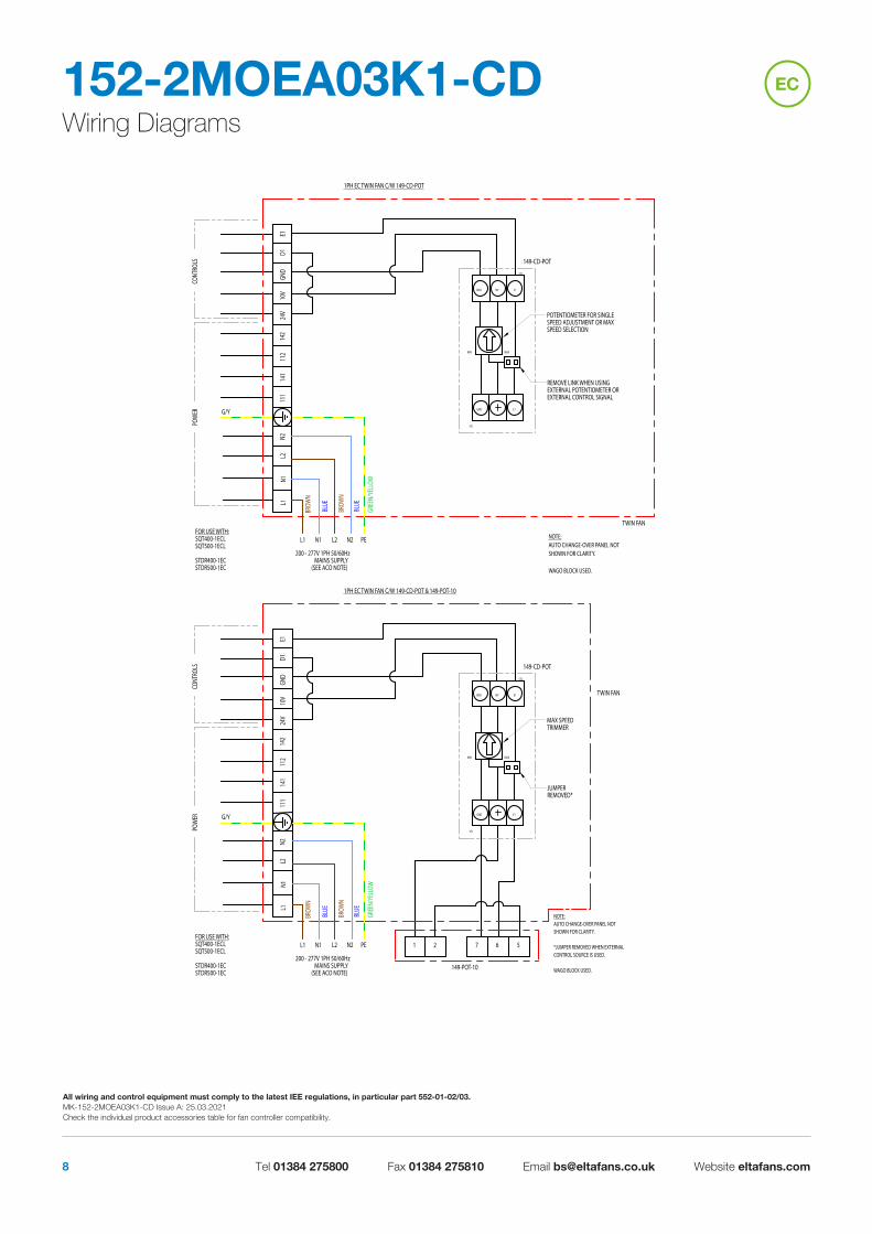
Wiring Diagrams152-2MOEA03K1-CD EC
NOTE:AUTO CHANGE-OVER PANEL NOTSHOWN FOR CLARITY.
*JUMPER REMOVED WHEN EXTERNALCONTROL SOURCE IS USED.
WAGO BLOCK USED.
G/Y
PEN2L2N1L1
1PH EC TWIN FAN C/W 149-CD-POT & 149-POT-10
L2N2
111
141
112
142
TWIN FAN
BLUE
BROW
N
GREE
N/YE
LLOW
1
149-POT-10
5672
GND 10V E1
MIN MAX
E1GND
ST1
ST2
149-CD-POT
E1D1
10V
24V
GND
N1L1
BROW
N
BLUE
POW
ERCO
NTRO
LS
MAX SPEEDTRIMMER
JUMPERREMOVED*
FOR USE WITH:SQT400-1ECLSQT500-1ECL
STDR400-1ECSTDR500-1EC
200 - 277V 1PH 50/60HzMAINS SUPPLY
(SEE ACO NOTE)
NOTE:AUTO CHANGE-OVER PANEL NOTSHOWN FOR CLARITY.
WAGO BLOCK USED.
G/Y
PEN2L2N1L1
1PH EC TWIN FAN C/W 149-CD-POT
L2N2
111
141
112
142
TWIN FAN
BLUE
BROW
N
GREE
N/YE
LLOW
GND 10V E1
MIN MAX
E1GND
ST1
ST2
149-CD-POT
E1D1
10V
24V
GND
N1L1
BROW
N
BLUE
POW
ERCO
NTRO
LS
POTENTIOMETER FOR SINGLESPEED ADJUSTMENT OR MAXSPEED SELECTION
REMOVE LINK WHEN USINGEXTERNAL POTENTIOMETER OREXTERNAL CONTROL SIGNAL
FOR USE WITH:SQT400-1ECLSQT500-1ECL
STDR400-1ECSTDR500-1EC
200 - 277V 1PH 50/60HzMAINS SUPPLY
(SEE ACO NOTE)
C
All wiring and control equipment must comply to the latest IEE regulations, in particular part 552-01-02/03. MK-152-2MOEA03K1-CD Issue A: 25.03.2021Check the individual product accessories table for fan controller compatibility.

Elta Fans Limited has a policy of continuous product development and improvement and therefore reserves the right to supply products which may differ from those illustrated and described in this publication. Confirmation of dimensions and data will be supplied on request. 9
Wiring Diagrams152-2MOEA03K3-CD EC
NOTE:AUTO CHANGE-OVER PANEL NOTSHOWN FOR CLARITY.
WAGO BLOCK USED.
BLAC
K
GREY
BROW
N
BLAC
K
GREY
BROW
N
PEL3L2L1L3L2L1
2L1
2L2
2L3
1L3
1L2
G/Y
3PH EC TWIN FAN C/W 149-CD-POT
111
141
112
142
TWIN FAN
GREE
N/YE
LLOW
GND 10V E1
MIN MAX
E1GND
ST1
ST2
149-CD-POT
E1D1
10V
24V
GND
1L1
POW
ERCO
NTRO
L
POTENTIOMETER FOR SINGLESPEED ADJUSTMENT OR MAXSPEED SELECTION
REMOVE LINK WHEN USINGEXTERNAL POTENTIOMETER OREXTERNAL CONTROL SIGNAL
FOR USE WITH:SQT500-3ECL
STDR500-3EC380-480V 3PH 50/60Hz
MAINS SUPPLY (SEE ACO NOTE)
NOTE:AUTO CHANGE-OVER PANEL NOTSHOWN FOR CLARITY.
*JUMPER REMOVED WHEN EXTERNALCONTROL SOURCE IS USED.
WAGO BLOCK USED
BLAC
K
GREY
BROW
N
BLAC
K
GREY
BROW
N
PEL3L2L1L3L2L1
2L1
2L2
2L3
1L3
1L2
G/Y
3PH EC TWIN FAN C/W 149-CD-POT & 149-POT-10
111
141
112
142
TWIN FAN
GREE
N/YE
LLOW
1
149-POT-10
5672
GND 10V E1
MIN MAX
E1GND
ST1
ST2
149-CD-POT
E1D1
10V
24V
GND
1L1
POW
ERCO
NTRO
L
MAX SPEEDTRIMMER
JUMPERREMOVED*
FOR USE WITH:SQT500-3ECL
STDR500-3EC380-480V 3PH 50/60Hz
MAINS SUPPLY (SEE ACO NOTE)C
All wiring and control equipment must comply to the latest IEE regulations, in particular part 552-01-02/03. MK-152-2MOEA03K3-CD Issue C: 25.03.2021Check the individual product accessories table for fan controller compatibility.

Tel 01384 275800 Fax 01384 275810 Email [email protected] Website eltafans.com10
Notes
QUIETFLOW TWIN SQT

Elta Fans Limited has a policy of continuous product development and improvement and therefore reserves the right to supply products which may differ from those illustrated and described in this publication. Confirmation of dimensions and data will be supplied on request. 11
Notes
QUIETFLOW TWIN SQT

535-IOM0031 Issue D
eltafans.com
Tel +44 (0) 1384 275800Fax +44 (0) 1384 275810Email [email protected]
46 Third Avenue, Pensnett Trading Estate, Kingswinford, West Midlands, DY6 7US United Kingdom
Tel +44 (0) 1489 566500Fax +44 (0) 1489 566555Email [email protected] / [email protected]
17 Barnes Wallis Road, Segensworth East Industrial Estate, Fareham, Hampshire, PO15 5ST United Kingdom
Applied Technology & Building Services Export
Building Services
BS EN ISO 9001:2015 FM 556465
A member ofHEVAC ASSOCIATION