Quickset Product Catalog 2014 - Moog€¦ · Abbreviated list of qualified products. Contact your...
40
PRODUCT CATALOG 2014
Transcript of Quickset Product Catalog 2014 - Moog€¦ · Abbreviated list of qualified products. Contact your...

PRODUCT CATALOG2014

A HisTORy Of DisTinCTiOn
Our history begins over seventy-five years ago with QuickSet establishing itself as the principal supplier of heavy-duty tripods and positioners. Over the years QuickSet distinguished itself by satisfying demands for larger payloads, remote controls, and greater pointing accuracy for various military, government, and industrial applications.
Over fifty years ago, Moog founder, William C. Moog – inventor, entrepreneur, and visionary – developed the electro-hydraulic servovalve, a device that translates tiny, electrical impulses into precise and powerful movement. Today, Moog technology enhances performance in a variety of markets and applications, from commercial aircraft cockpits, to power-generation turbines, to mission critical spacecraft and defense weaponry.
In 2007, Moog acquired QuickSet to further its commitment to mission success and comprehensive project management, continuing to meet the demanding requirements of their customers. Together we are leading the way with technological innovations that tackle the demands of military applications, combat vehicles, border surveillance, and the Department of Homeland Security requirements.
“A BeTTeR WAy” TO RUn A COmPAny
From experience, Bill Moog knew that work environment played an important role in any company’s success. He had some unique ideas about a “better way” to run a company – treating employees with trust and respect.
Bill Moog’s sense of innovation went far beyond product design. He believed that people would be more creative, committed, and productive in a work environment where they felt trusted, respected, and rewarded. This set of ideas came to be known as the Moog Philosophy.
mOOG: An innOvATive enviROnmenT
What other companies are now just discovering, we have known all along – that people work best in an environment where they feel valued, involved, and empowered. As Bill Moog once said, “We believe in the people who work here.... having trust and confidence in our people is the only way we know.” We are a highly successful company built upon a community of hardworking, talented, and dedicated people.
In the fall of 1997, Bill Moog passed away. In a tribute to Bill shortly after his death, Bob Brady, Executive Chairman of Moog, had this to say about our company:
“Every day an extraordinary group of people come together to devote their time and energy to build the best product of its type built anywhere in the world...and to deliver that product to the most demanding customers in the world.
“Those customers can be assured that the product bearing Bill’s name is the best product that mankind can make...and it will be better next month, and better next year. This is our lasting tribute to Bill.”
We think that says it all.
www.quickset.com2
moogmoog

www.quickset.com 3
Moog – An Introduction Inside Cover
Project Design and Management 4
Integrated Systems Introduction 6
General Product Information 8 Thermal Camera Selection 9 GeminEye 10 EXO High Definition Camera Systems 12 Pilot 13 Single Visible Systems 14 Single Thermal Systems 15 Dual Visible/Thermal Systems 16
Camera Housings 17
Accessories 18
Rapid Deployment Kit 19
Precise Positioning Systems QPT-20 Series 20 QPT-35 Series 21 QPT-50 Series 22 QPT-90 Series 23 QPT-130 Series 24 QPT-200 and 500 Series 25 QPT-RF Series 26 Mercury Series 27 Taurus Series 28 Low Profile Yoke 29 Analog Series 30Tripods Pegasus Series 31 Samson Series 32 Hercules Series 34 Gibraltar Series 35
Tracking Systems 36
Controllers and GUI 37
Cables 39
Table of ContentsTable of Contents

www.quickset.com
Whether it’s designing products for a new market need or making adjustments to an existing system, the Moog team of in-house engineers provide full design and rapid prototyping for our customers.
Moog engineers have a reputation for building strong relationships with customers’ engineers. Our people roll up their sleeves and become members of our customers’ project teams, doing whatever it takes to understand the challenges and design effective solutions.
We believe in taking a true systems engineering approach, giving our teams a broad perspective on all the various systems, components, and technical issues involved. In this way, Moog engineers can bring new energy, ideas, and viewpoints to the entire project, while continuing their focus on specialized areas of expertise.
• Systems Engineering • Mechanical Design• Electrical Design
• OEM Design• Software Design• Project Engineering
• Product Engineering• Manufacturing Engineering• Quality Engineering
• On-Site and Field Testing• Rapid Prototyping• Integrated System Design
4
Design and managementProject Design and management

Municipal Security
Border Security
Critical Infrastructure Security
Airports and PerimeterIntrusion Detection Systems
Driver Vision Enhancer Systems
Ports and Harbors
5
Applications

integrated systems www.quickset.com
Security and surveillance are critical 24/7 operations that cannot afford downtime – no matter what visibility, terrain, or environmental challenges are present. A well designed integrated sensor imaging system is your best defense in protecting your assets.
Moog is an industry leader in integrated sensor systems for a wide range of markets and mission critical applications. Our strategy is to supply customizable sensor solutions that are robust, reliable and highly supportable - providing the best possible protection of your assets:
• Highly ruggedized • Quality and durable products reduce cost of ownership
• Various payload integration • Built to withstand extreme environments
• Quick change modules with true plug and play performance • Excellent performance in challenging terrains
6
integrated sensor systemsintegrated sensor systems
visible Cameras infrared Cameras Laser Range finders non-Lethal Deterrents Active imaging/ Communications Devices* Additional integration Options*
Detection, Recognition, and ID Detection, Recognition & ID Distance to Target Acoustic Hailers Radar Systems and RF Antenna Pointing Chem-Bio Sensors
Long Range Surveillance Smoke, Fog, and Haze Penetration Fixed Installation, Moving Targets Directed Communication Slew to Cue Radar and GPS Systems Radiation Sensors
Identification Through Glass Barriers Long Wave Infrared (LWIR) Mobile Installation, Mobile Targets Dazzler Point to Point Microwave Threat Detection
Still Shots and Full Motion Video Medium Wave Infrared (MWIR) Geolocation High-Intensity Illumination Scanning Systems Threat Classification
HD/IP/Megapixel Imaging Short Wave Infrared (SWIR) Command and Control of Unmanned Systems Chemical Cloud Detection
Industrial Inspection / Explosion Proof Thermal Signature and Change Detection Satellites Lighting Systems

integrated systems www.quickset.com
visible Cameras infrared Cameras Laser Range finders non-Lethal Deterrents Active imaging/ Communications Devices* Additional integration Options*
Detection, Recognition, and ID Detection, Recognition & ID Distance to Target Acoustic Hailers Radar Systems and RF Antenna Pointing Chem-Bio Sensors
Long Range Surveillance Smoke, Fog, and Haze Penetration Fixed Installation, Moving Targets Directed Communication Slew to Cue Radar and GPS Systems Radiation Sensors
Identification Through Glass Barriers Long Wave Infrared (LWIR) Mobile Installation, Mobile Targets Dazzler Point to Point Microwave Threat Detection
Still Shots and Full Motion Video Medium Wave Infrared (MWIR) Geolocation High-Intensity Illumination Scanning Systems Threat Classification
HD/IP/Megapixel Imaging Short Wave Infrared (SWIR) Command and Control of Unmanned Systems Chemical Cloud Detection
Industrial Inspection / Explosion Proof Thermal Signature and Change Detection Satellites Lighting Systems
*Payloads provided and integrated by the OEM.
Our experienced program management team has the hands-on knowledge to guide you through building a solid foundation for asset protection and threat intervention.
Key Considerations When Building an Integrated Sensor System:
• Potential threats to be detected • Asset protection objectives
• Assets to be protected • Environmental challenges
• Terrain challenges • Detection range required
7

www.quickset.com
PAn AnD TiLT COnfiGURATiOns
Moog pan and tilt models have been divided into several basic configurations:
1. Analog2. IC: Integrated Control3. ICM: Integrated Control Marine4. ICMS: Integrated Control Marine Sentry5. ICM – RF: Integrated Control Marine Radio Frequency6. ICMS – RF: Integrated Control Marine Sentry Radio Frequency
Analog: All electrical power is delivered from the controller almost directly to the pan and tilt axis motors. There is one motor for each axis.
iC: Integrated Control (IC) includes electrical drivers from external controllers to inside the pan and tilt.
marine: Pan and tilts are housed in rugged, welded, sealed enclosures that increase the range of its use to extreme and challenging environments. They are designed to be used primarily in coastal, marine, frigid, humid, dirty, sandy, and salty atmospheres. (Note: Marine versions of the QPT-20 use extruded aluminum housings.)
sentry: The Sentry designation refers to the use of higher reliability stepper motor technology. Stepper motor drives are used for applications where constant velocity, higher dynamic range in rotational speed, torque, and incremental movement capability are required over that of the basic brush motor units.
Rf: These units provide a means to pass RF signals through the body of the pan and tilt for continuous rotation applications.
PAn AnD TiLT WiRinG AnD CABLe COnfiGURATiOns
formed Tabletop (fT): Basic tabletop; no payload interconnections going into or out of the pan and tilt to the payload.
formed Tilt A (fTA): Formed tabletop with a single Mil-Spec I/O connector port located at the tilt axis. Pre-wired internal connections to this port allow the payload to interface with the power, serial control, lens control, A/D conversion, and capabilities of the pan and tilt.
formed Tilt B (fTB): Formed tabletop with Mil-Spec I/O connector port located at the tilt axis. Pre-wired I/O connections to this connector go directly to the base connector. This allows the option to connect directly to the payload.
Universal: Wiring interface design incorporates multiple Mil-Spec connectors on the tabletop pre-wired for data, power and sensor control.
single ended Cables (se): This cable configuration extends directly from the pan and tilt to the control point without any breakouts when the controller, power supply, and video interfaces are co-located at the same point.
Bifurcated Cables (Bi): This configuration takes into consideration the fact that DC power, required by our IC based units, cannot be located as far away from the pan and tilt as a control site can. Serially controlled pan and tilts, over copper wire, can be located as far as 4,000 ft. away using RS-422 / 485 formats. Ethernet based systems can be located up to 328 ft. away without a switch.
TesTeD AnD CeRTifieD
Moog products have been qualified to the following performance levels:
Product Repeatability (Line of Sight)
Salt Spray TestingMIL-STD-810F
Sand & Dust Penetration(IP 6X)
Water Spray Penetration(IP X6)
Temp Range(Up to -40°C)
Vibration(HMMWV)
Shock(HMMWV)
GeminEye 0.25 deg Passed Passed Passed Passed Passed (8 lbs) Passed (8 lbs)
Apollo Class 0.05 deg Passed Passed Passed Passed Passed (50 lbs) Passed (50 lbs)
QPT-90 0.05 deg Passed Passed Passed Passed Passed (90 lbs) Passed (90 lbs)
QMP-R 0.05 deg Qualified by Similarity Passed Passed Passed Passed (150 lbs) Passed (150 lbs)
Abbreviated list of qualified products. Contact your sales rep for a full list.
AvAiLABLe sysTem COLORs – sTAnDARD
Marine White – MWS* Marine Navy Gray – MNG Flat Black – FB37030 #CARC Black – CBLK
Desert Tan – BGP33446 #CARC – Desert Tan – BGC
Olive Drab – OD34084 #CARC Green – GRN
* Unless otherwise noted MWS is the default finish# Federal Standard 595BContact your sales rep for custom finishes and pricing
8
General Product informationGeneral Product information
Unless Otherwise Noted, product falls under the jurisdiction of the United States Government under the EAR (Export Administration Regulations) as EAR-99. Please contact our company Export Representative at +1-716-687-4930 for additional export information.

9Thermal Camera selection www.quickset.com
Thermal Camera selectionThermal Camera selection
Gemineye THeRmAL imAGinG RAnGes
9 mm Lens
69˚ HFOV
250 meters-Detection
63 meters-Recognition
31 meters-Identification
13 mm Lens
45˚ HFOV
390 meters-Detection
95 meters-Recognition
47 meters-Identification
19 mmLens
32˚ HFOV
570 meters-Detection
144 meters-Recognition
72 meters-Identification
25 mmLens
25˚ HFOV
820 meters-Detection
210 meters-Recognition
104 meters-Identification
35 mm Lens
18˚ HFOV
1140 meters-Detection
280 meters-Recognition
142 meters-Identification
50 mmLens
12 4˚ HFOV
1500 meters-Detection
380 meters-Recognition
190 meters-Identification
60 mmLens
10 4˚ HFOV
1750 meters-Detection
450 meters-Recognition
225 meters-Identification
100 mmLens
25˚ HFOV
2450 meters-Detection
650 meters-Recognition
330 meters-Identification
THeRmAL CAmeRA seLeCTiOn
ResOLUTiOn f/# fOv (H x v)9 mm 640 x 480 (NTSC) - 640 x 512 (PAL) 1.25 6.9˚ x 56˚
13 mm 640 x 480 (NTSC) - 640 x 512 (PAL) 1.25 45˚ x 37˚
19 mm 640 x 480 (NTSC) - 640 x 512 (PAL) 1.25 32˚ x 26˚
25 mm 640 x 480 (NTSC) - 640 x 512 (PAL) 1.1 25˚ x 20˚
35 mm 640 x 480 (NTSC) - 640 x 512 (PAL) 1.2 18˚ x 14˚
50 mm 640 x 480 (NTSC) - 640 x 512 (PAL) 1.2 12.4˚ x 9.9˚
60 mm 640 x 480 (NTSC) - 640 x 512 (PAL) 1.25 10.4˚ x 8.3˚
100 mm 640 x 480 (NTSC) - 640 x 512 (PAL) 1.6 6.2˚ x 5.0˚
15 -100 mm 640 x 480 (NTSC) - 640 x 512 (PAL) 1.4 6.2˚ x 5.0˚ to 42˚ x 54˚
640x512 sensor w/ 9mm lens
640x512 sensor w/ 35mm lens
640x512 sensor w/ 13mm lens
640x512 sensor w/ 50mm lens
640x512 sensor w/ 19mm lens
640x512 sensor w/ 60mm lens
640x512 sensor w/ 25mm lens
640x512 sensor w/ 100mm lens
These products are subject to export control laws and regulations of the United States government and fall under the control jurisdiction of either ITAR or EAR regulations. Please contact our company Export Representative at +1-716-687-4930 for additional export information

integrated systems www.quickset.com
PRODUCT OveRvieW
The GeminEye® Modular Imaging Systems embrace high performance in a small package, and are designed to be configured for multiple applications.
The GeminEye can be configured with single or dual camera blocks for day, night or day/night capability. Various wavelength band sensors and illuminator modules are available. As a system, GeminEye is completely upgradable with image blocks swappable in the field by the user.
PRODUCT sPeCifiCATiOns
Available features • Compact / light weight• Quick-change camera modules (blocks) with true
plug and play performance• Network controllable or dedicated (UniCom®LT)
controller• HD Daylight Camera Systems available• Mil-STD-810F, IP67, sealed and
pressurized camera housings
• Qualified to random vibration, Salt/FogMIL-STD-810F, Method 509.4
• 10-30 VDC operations• Continuous pan rotation• Mobile or inverted operation• Mounting kits• Illuminators with Quick-Site™ boresight mechanism• Pelco compatible
visiBLe BLOCKs
Part Number Description Sensor Size Focal Length Optical Zoom Lens Type Focus Type
GVB-S10XXN VISB 1/4" CCD 995 3.4-122 12x 36x ZA N 1/4” CCD 3.5 - 98 28X Zoom Auto
GVB-S11XXN VISB 1/4" CCD 1020 3.4-122 12x 36x ZA N 1/4” CCD 3.4 - 122 36X Zoom Auto
THeRmAL BLOCKs*
Part Number Description Sensor Size Pixel Size FOV Focal length Digital Zoom ƒ Lens Type Focus Type
GTB-F10F1NF LWIR 320x256 25µ 25mm 4x ƒ1.1 F F NF 320 x 256 25 µ 18° x 14° 25mm 4X ƒ1.1 Fixed Fixed
GTB-F10F2NF LWIR 320x256 25µ 50mm 4x ƒ1.2 F F NF 320 x 256 25 µ 9.1° x 6.9° 50mm 4X ƒ1.2 Fixed Fixed
GTB-F10F3NF LWIR 320x256 25µ 100mm 4x ƒ1.6 F F NF 320 x 256 25 µ 4.6° x 3.4° 100mm 4X ƒ1.6 Fixed Fixed
GTB-F11F2NF LWIR 640x512 17µ 50mm 4x ƒ1.2 F F NF 640 x 512 17 µ 12.4° x 9.9° 50mm 4X ƒ1.2 Fixed Fixed
GTB-F11F3NF LWIR 640x512 17µ 100mm 4x ƒ1.6 F F NF 640 x 512 17 µ 6.2° x 5° 100mm 4X ƒ1.6 Fixed Fixed
GTB-F11Z1NF LWIR 640X512 17µ 15-100 4X ƒ1.4 ZR NF 640 x 512 17 µ 39.9° x 6.2° 15-100mm 4X ƒ1.4 Continuous Zoom Remote
iLLUminATOR BLOCKs
Part Number Description Old Part Number F O V Wavelength
GIB-LU10 Illuminator Block 10° FOV GIB-SC10 10° 850nm
GIB-LU20 Illuminator Block 20° FOV GIB-SC20 20° 850nm
GIB-LU30 Illuminator Block 30° FOV GIB-SC30 30° 850nm
GIB-LU60 Illuminator Block 60° FOV GIB-SC60 60° 850nm
Dual Camera Gemineye
visiBLe AnD THeRmAL CAmeRA sysTems*
Part Number DescriptionThermal Camera
Visible Block Thermal Block
Illuminator BlockSensor Size FOV Focal Length ƒ Lens Type Focus Type
GVTS-S11XXN-F10F2NF GEYE DUAL SYS VISB 1/4” CCD 36X ZOOM 320 x 256 9.1° x 6.9° 50mm ƒ1.2 Fixed Fixed GVB-S11XXN GTB-F10F2NF N/A
GVTS-S10XXN-F10F2NF GEYE DUAL SYS VISB 1/4” CCD 28X ZOOM 320 x 256 9.1° x 6.9° 50mm ƒ1.2 Fixed Fixed GVB-S10XXN GTB-F10F2NF N/A
GVTS-S10XXN-F10F1NF GEYE DUAL SYS VISB 1/4” CCD 28X ZOOM 320 x 256 18° x 14° 25mm ƒ1.1 Fixed Fixed GVB-S10XXN GTB-F10F1NF N/A
GVTS-S11XXN-F10F1NF GEYE Dual SYS VISB 1/4” CCD 36X ZOOM 320 x 256 18° x 14° 25mm ƒ1.1 Fixed Fixed GVB-S11XXN GTB-F10F1NF N/A
GVTS-S11XXN-F11Z1NF GEYE Dual SYS Sony1020 LWIR 640 w/15-100m 640 X 512 39.9° - 6.2° 15- 100 ƒ1.4 Continuous Zoom Remote GVB-S11XXN GTB-F11Z1NF N/A
GVTS-S10XXN-F11Z1NF GEYE Dual SYS VISB 1/4” CCD 28X ZOOM 640 X 512 39.9° - 6.2° 15- 100 ƒ1.4 Continuous Zoom Remote GVB-S10XXN GTB-F11Z1NF N/A
GVTS-S11XXN-F11F3NF GEYE DUAL SYS SONY 1020 LWIR 640 100MM NF 640 X 512 6.2° x 5° 100mm ƒ1.6 Fixed Fixed GVB-S11XXN GTB-F11F3NF N/A
GVTS-S10XXN-F11F2NF GEYE DUAL SYS VISB 1/4” CCD 28X ZOOM 640 X 512 12.4° x 9.9° 50mm ƒ1.2 Fixed Fixed GVB-S10XXN GTB-F11F2NF N/A
GVTS-S11XXN-F11F2NF GEYE DUAL SYS VISB 1/4” CCD 36X ZOOM 640 X 512 12.4° x 9.9° 50mm ƒ1.2 Fixed Fixed GVB-S11XXN GTB-F11F2NF N/A
GVTS-S11XXN-F10F3NF GEYE DUAL SYS SONY 1020 LWIR 320 100MM NF 320 x 256 4.6° x 3.4° 100mm ƒ1.6 Fixed Fixed GVB-S11XXN GTB-F10F3NF N/A
10
Gemineye systemsGemineye systems

Gemineye ACCessORies
Part Number Description
L Brackets
LT-475LB QPT-LT “L”BRACKET SLAVE SIDE w/ Pass-through wiring
LT-450LB QPT-LT “L”BRACKET DRIVE SIDE w/ Pass-through wiring
Power Supply Outdoor
7-08964 Power Supply, Outdoor, Pole Mountable, 24VDC, 10.2A
Cables
6-20151-10/25/50 Power (2- 18 AWG), Aux (2 - 18AWG), 2x Video, Serial Comm to 4x connector, Gnd, CAT-5 to RJ45, available in 10, 25, and 50 ft lengths
Bifurcated Cables
6-20127-16-16 16 ft Each (A) Power (2- 18 AWG), (B) Aux (2 - 18AWG), 2x Video, Serial Comm to 4x connector, Gnd, CAT-5
6-20127-50-50 50 ft Each (A) Power (2- 18 AWG), (B) Aux (2 - 18AWG), 2x Video, Serial Comm to 4x connector, Gnd, CAT-5
Outdoor Power Supply AC Input Cables
6-19235-8/16/50 Cable, Input Power, 115VAC, available in 8, 16, and 50ft lengths
Tripod
4-74434-FB Tripod Samson 3 Section Leg No Column 4”Ft Plt
4-74432-FB Tripod Samson 2 Section Leg w/ PTU Adaptor Mount
Test Stand Kit
7-17555 Kit Test Stand GeminEye
Mounts
7-17567 Pedestal Mount
7-17564 Wall Mount
7-17565 Pole adapter (requires addition of wall mount)
7-17566 Corner adapter (requires addition of wall mount)
Video Management
LT-V1CUBE IP Video Encoder Cube
integrated systems www.quickset.com 11
visiBLe sensOR OnLy sysTems
Part Number DescriptionThermal Camera
Visible Block Thermal Block
Illuminator BlockSensor Size FOV Focal Length ƒ Lens Type Focus Type
GVS-S10XXN GeminEye Single V SYS-VISB 1/4” CCD 28X ZOOM N/A N/A N/A N/A N/A N/A GVB-S10XXN N/A N/A
GVS-S11XXN GeminEye Single V SYS-VISB 1/4” CCD 36X ZOOM N/A N/A N/A N/A N/A N/A GVB-S11XXN N/A N/A
THeRmAL sensOR OnLy sysTems
Part Number DescriptionVisibleCameraModel
Thermal CameraVisible Block Thermal
BlockIlluminator
BlockSensor Size FOV Focal Length ƒ Lens Type Focus Type
GTS-F10F1NF GeminEye Single T SYS-LWIR 320 w/ 25mm on LT-901 N/A 320 x 256 18° x 14° 25mm ƒ1.1 Fixed Fixed N/A GTB-F10F1NF N/A
GTS-F10F2NF GeminEye Single T SYS-LWIR 320 w/ 50mm on LT-901 N/A 320 x 256 9.1° x 6.9° 50mm ƒ1.2 Fixed Fixed N/A GTB-F10F2NF N/A
GTS-F10F3NF GeminEye Single T SYS-LWIR 320 w/ 100mm on LT-901 N/A 320 x 256 4.6° x 3.4° 100mm ƒ1.6 Fixed Fixed N/A GTB-F10F3NF N/A
GTS-F11F3NF GeminEye Single T SYS-LWIR 640 w/ 100mm on LT-901 N/A 640 X 512 6.2° x 5° 100mm ƒ1.6 Fixed Fixed N/A GTB-F11F3NF N/A
GTS-F11Z1NF GeminEye Single T SYS-LWIR 640 w/ 15-100mm on LT-901 N/A 640 X 512 39.9° - 6.2° 15- 100 ƒ1.4 Continuous Zoom Remote N/A GTB-F11Z1NF N/A
iLLUminATOR sysTems
Part Number Description Illuminator FOV Options Visible Block Illuminator Block
GVS-S10XXN-LU10/20/30/60 GeminEye Illuminator System with VISB 1/4” CCD 28X ZOOM 10°, 20°, 30°, 60° GVB-S10XXN GIB-LU10/20/30/60
GVS-S11XXN-LU10/20/30/60 GeminEye Illuminator System with VISB 1/4” CCD 36X ZOOM 10°, 20°, 30°, 60° GVB-S11XXN GIB-LU10/20/30/60
All visible camera part numbers are NTSC, and all thermal camera part numbers are fast frame rate. PAL and slow frame rate options are also available.
* These products are subject to export control laws and regulations of the United States government and fall under the control jurisdiction of either ITAR or EAR regulations. Please contact our company Export Representative at +1-716-687-4930 for additional export information.
4-74434-fB
4-74432-fB
HD Gemineye - AnALOG COmPOnenT viDeO
Part Number DescriptionHD Camera Specifications Thermal Camera Specification*
Image Sensor Lens Signal System No of Pixels Angle of View Video Output Sensor Size Lens
GVSHD-S13XXN Component HD GeminEye - 1/2.8 CMOS Visible Camera Only
1/2.8-type ‘Exmor’ CMOS
30x Optical Zoom, f=4.3 mm (wide) ~
129.0 mm (tele), F1.6
to F4.
HD: 1080p/29.97, 1080p/25, 1080i/59.94 (frame out 29.97 PsF),
1080i/50 (frame out: 25PsF) 720/59.94p, 720/50p, 720p/29.97, 720p/25
Approx. 3.27 million
H) 1080p/30 mode: 55.4° (wide end)
to 2.9° (tele end)
720p/60, 30 mode: 37.6° (wide end)
to 1.95° (tele end)
HD Analog: Component
Y/Pb/Pr
n/a
GVTSHD-S13XXN-F10F1NF-S Component HD GeminEye - 1/2.8 CMOS Visible & 25mm 320x256 thermal
320x256
25mm
GVTSHD-S13XXN-F10F3NF-S Component HD GeminEye - 1/2.8 CMOS Visible & 50mm 320x256 thermal 50mm
GVTSHD-S12XXN-F11Z1NF-S Component HD GeminEye - 1/2.8 CMOS Visible & 100mm 320x256 thermal 100mm
GVTSHD-S13XXN-F10Z1NF-S Component HD GeminEye - 1/2.8 CMOS Visible & 15-100mm 320x256 thermal 15-100mm zoom
GVTSHD-S13XXN-F11F1NF-S Component HD GeminEye - 1/2.8 CMOS Visible & 25mm 640x480 thermal
640x480
25mm
GVTSHD-S13XXN-F11F2NF-S Component HD GeminEye - 1/2.8 CMOS Visible & 50mm 640x480 thermal 50mm
GVTSHD-S13XXN-F11F3NF-S Component HD GeminEye - 1/2.8 CMOS Visible & 100mm 640x480 thermal 100mm
GVTSHD-S13XXN-F11Z1NF-S Component HD GeminEye - 1/2.8 CMOS Visible & 15-100mm 640x480 thermal 15-100mm zoom

High-Definition systems www.quickset.com
PRODUCT OveRvieW
Dual integrated sensor systems offer the best of both worlds for day / night, continuous surveillance. The EXO GeminEye provides 24/7, clear and accurate HD and thermal observation through difficult environmental challenges. The integration of dual sensors increases the level of intelligence available to your team. Detection is significantly enhanced allowing appropriate response to potential threats.
AvAiLABLe feATURes • Cost effective, easy integration • Detection in obscure environments • 24/7/365 surveillance in challenging
environments • Scalable to augment existing systems • Networked control • Integrated H.264 and M-JPEG encoder
with real time streaming video
PRODUCT OveRvieW
Moog EXO Series High Definition (HD) Network Camera Systems, with H.264 High Profile and ONVIF support, are the professional’s choice for capturing brilliant, 1080P full HD video in extreme applications. The EXO Series is built tough to withstand extreme temperature ranges, power surges, heavy impacts, corrosion, and even bullets. EXO Camera Systems are available in three Pan-Tilt-Zoom (PTZ) models: EXO Vandal Resistant, EXO Pressurized, and EXO Corrosion Resistant, and two Fixed models: EXO Vandal Resistant and EXO Fixed Pressurized.
Available features • HD 1080P models 0.095lx min. illumination• 20x and 30x optical zoom, Day / Night with auto IR-cut filter, Wide
Dynamic Range• Dual stream: H.264 and M-JPEG• Multiple models suited to different extreme environments• ONVIF compliant• Meets NEMA TS2 standards • Built-in surge protection (Power, alarms, and network / video)• Auto Image Stabilization (On 30x models)• Local storage with built-in memory card slot
vAnDAL ResisTAnTEXVW7C2-2
CORROsiOn ResisTAnTEXSS7C2-3
exO Gemineye - HD iP viDeO
Part Number DescriptionHD Camera Specifications Thermal Camera Specification*
Image Sensor Lens Signal System No of Pixels Angle of View Video Output Sensor Size Lens
EXGVSHD-S13XXN EXO IP HD GeminEye - 1/2.8 CMOS Visible Camera Only
1/2.8-type ‘Exmor’ CMOS
30x Optical Zoom, f=4.3 mm (wide) ~
129.0 mm (tele), F1.6
to F4.
HD: 1080p/29.97, 1080p/25, 1080i/59.94 (frame out 29.97 PsF),
1080i/50 (frame out: 25PsF) 720/59.94p, 720/50p, 720p/29.97, 720p/25
Approx. 3.27 million
(H) 1080p/30 mH) 1080p/30 mode: 55.4°
(wide end) to 2.9° (tele end)
720p/60, 30 mode: 37.6° (wide end) to
1.95° (tele end)
H.264 High Profile
n/a
EXGVTSHD-S13XXN-F10F1NF EXO IP HD GeminEye - 1/2.8 CMOS Visible & 25mm 320x256 thermal
320 x 256
25mEXGVTSHD-S13XXN-F10F9NF EXO IP HD GeminEye - 1/2.8 CMOS Visible & 35mm 320x256 thermal 35mmEXGVTSHD-S13XXN-F10F2NF EXO IP HD GeminEye - 1/2.8 CMOS Visible & 50mm 320x256 thermal 50mm
EXGVTSHD-S13XXN-F10F10NF EXO IP HD GeminEye - 1/2.8 CMOS Visible & 60mm 320x256 thermal 60mm
EXGVTSHD-S13XXN-F10F3NF EXO IP HD GeminEye - 1/2.8 CMOS Visible & 100mm 320x256 thermal 100mm
EXGVTSHD-S13XXN-F10Z1NF EXO IP HD GeminEye - 1/2.8 CMOS Visible & 15-100mm 320x256 thermal 15-100mm zoom
EXGVTSHD-S13XXN-F11F1NF EXO IP HD GeminEye - 1/2.8 CMOS Visible & 25mm 640x480 thermal
640 x 512
25m
EXGVTSHD-S13XXN-F11F9NF EXO IP HD GeminEye - 1/2.8 CMOS Visible & 35mm 640x480 thermal 35mm
EXGVTSHD-S13XXN-F11F2NF EXO IP HD GeminEye - 1/2.8 CMOS Visible & 50mm 640x480 thermal 50mm
EXGVTSHD-S13XXN-F11F10NF EXO IP HD GeminEye - 1/2.8 CMOS Visible & 60mm 640x480 thermal 60mm
EXGVTSHD-S13XXN-F11F3NF EXO IP HD GeminEye - 1/2.8 CMOS Visible & 100mm 640x480 thermal 100mm
EXGVTSHD-S13XXN-F11Z1NF EXO IP HD GeminEye - 1/2.8 CMOS Visible & 15-100mm 640x480 thermal 15-100mm zoom
12
High Definition systemsHigh Definition Camera systemsNEW!
* These products are subject to export control laws and regulations of the United States government and fall under the control jurisdiction of either ITAR or EAR regulations. Please contact our company Export Representative at +1-716-687-4930 for additional export information.
PRessURizeD fixeDEXPF5C-1
PRessURizeDEXRPF7C2-3
• 1080P full HD 3.27 Megapixel daylight camera
• Quick change daylight and thermal camera modules with true Plug and Play performance
PTz style features• Heavy-duty pan / tilt mechanism, including metal gearing and wide belts for long life
and unmatched durability, 360° continuous rotation• OptiClear lower dome offers industry leading clarity, durability and chemical resistance• Presets and 3 auto-tours, adjustable privacy zones
fixed style features• Pressurized and Vandal resistant models available• HD 720P / 60 fps• 12x Optical Zoom with Auto Focus

Pilot Dual Camera systemPilot Dual Camera systemNEW!
NEW!
integrated systems www.quickset.com
PRODUCT OveRvieW
The Pilot Surveillance Node features cutting edge surveillance capability in a rugged, reliable package; the type of performance you expect from Moog products. Its dual camera configuration and advanced design allow it to excel in situations where 24/7 surveillance capability is essential.
Applications for Pilot include situational awareness for military vehicles, local surveillance capability for first responders and remote sensing for unmanned ground vehicles.The combination of light weight and outstanding performance make it ideal for man portable systems that require a reliable system that is easy to set-up.
PRODUCT sPeCifiCATiOns
The visible spectrum (day) camera provides excellent performance in conditions ranging from bright day light to very low level ambient lighting. The LWIR spectrum (night) camera provides effective imaging throughout all times of the day and night. Together, they yield a complete picture of your region of interest. Pilot provides continuous rotation in pan and 180 degrees of travel in tilt. At speeds up to 100 deg/sec it can reach any point in its field of regard in about 1 second with position locking for high wind loads or mobile applications. It includes the newest electronics platform and software package ensuring scalability.
13
sysTem
Part Number Description Feedback Repeatability Pan Speed
Tilt Speed
Pan Range
Tilt Range Weight Power Communication Control
Protocols Dimensions
PLVTS-S14XXN-F10F1NFPilot Dual Camera System - 1/4” CCD
Visible & 25mm 320x256 thermal
Resonant Induction
<0.05° .005 - 200º/sec .005 - 100º/secContinuous
Rotation180° (± 90°) 16lbs
75w Max; 10-32VDC
RS-422/IPQuickSet
or Pelco D
8.20” (20.83 cm ) H x 10.74” (27.0 cm) WRotational Envelope
PLVTS-S14XXN-F10F2NFPilot Dual Camera System - 1/4” CCD
Visible & 50mm 320x256 thermal
PLVTS-S14XXN-F11F1NFPilot Dual Camera System - 1/4” CCD
Visible & 25mm 640x512 thermal
PLVTS-S14XXN-F11F2NFPilot Dual Camera System - 1/4” CCD
Visible & 25mm 640x512 thermal
visiBLe CAmeRA
Key Features Sensor Size Lens Lens Features Angle of View F/# Digital Zoom Output Format Minimum Illumination
– Wide Dynamic Range Technology– Auto IR-cut Filter Removal (Auto ICR)– Image Stabilization– High resolution & sensitivity Images– Advanced Spherical Privacy Zone– Slow AE Response Function
1/4” CCD Integrated
10 x Optical zoom,F1.8 to F2.9 f= 4.2 mm (wide) to 42.0
(tele)
46 ̊(wide end) to 4.6 ̊(tele end)
1.8 - 2.910X (120X with optical zoom)
NTSC or PAL1.0 lux (F1.8 NTSC:
1/60 sec, PAL: 1/50 sec)

integrated systems www.quickset.com
PRODUCT OveRvieW
Moog single visible integrated systems offer effective broad range surveillance solutions with unsurpassed reliability at an affordable price. Our strategy is to supply sensor solutions that are robust, reliable and highly supportable, and provide the best possible protection of your assets.
PRODUCT sPeCifiCATiOns
Available features • Quick plug and play features • Easily scalable to augment existing systems • Field replaceable modules • Individual remote-controlled cameras • 32 programmable preset locations • Programmable tours to accommodate specific
surveillance requirements
• Networked control • Ruggedized • Built to withstand extreme environments • Excellent performance in challenging terrains • High quality, durable products • Mobile applications available
sPeCifiCATiOns
System Part Numbers Visible Sensor Ranges Camera Lens FocusHFOV F/# min lux (F/1 2)
Pan Speed/Tilt SpeedWFOV NFOV WFOV NFOV Color B/W
PVS-90098 Short 1/4"/ 768 x 494 5 - 98mm Auto 55.8 2.1 1.35 3.7 0.65 — .005 - 25˚/sec .005 - 8˚/sec
PVS-90122 Short 1/4"/ 768 x 494 3.4 - 122.4mm Auto 57.8 1.7 1.6 4.5 1.4 — .005 - 25˚/sec .005 - 8˚/sec
PVS-90240 Short 1/2"/ 768 x 494 12 - 240mm Motor Remote 35.3 1.5 1.5 360 0.03 0.004 .005 - 25˚/sec .005 - 8˚/sec
PVS-90375 Medium 1/2"/ 768 x 494 375mm f/2.3 - 360 Motor Remote 23.2 0.99 2.3 360 0.03 0.004 .005 - 25˚/sec
.005 - 8˚/sec
PVS-90750 Long 1/2"/ 768 x 494 750mm f/4.6 - 720 Motor Remote 11.8 0.5 4.6 720 0.03 0.004 .005 - 25˚/sec
.005 - 8˚/sec
PVS-91500 Very Long 1/2"/ 768 x 494 1500mm f/3.8 - 6000 Motor Remote 14.6 0.25 3.8 6000 0.03 0.004 .005 - 25˚/sec
.005 - 8˚/sec
14
single visible systemssingle visible systems

integrated systems www.quickset.com
PRODUCT OveRvieW
Integrated thermal imaging systems provide the ability to detect threats normally invisible to the naked eye. When you need to quickly detect intrusions before they occur, a thermal integrated system is your first line of defense in asset protection. Thermal systems are ideal for detecting people, objects, and incidents in total darkness or challenging environmental situations.
PRODUCT sPeCifiCATiOns
Available features • Reliable, high level of accuracy • Detection in obscured environments • 365/24/7 surveillance • Easily scalable to augment existing systems • Network control
• 32 programmable preset locations • Programmable tours to accommodate specific
surveillance requirements • Ruggedized systems built to withstand extreme
environments
sPeCifiCATiOns
System Part Numbers Camera Thermal: Vox Microbolometer (LWIR) 7 5 – 13 5µm Focus
HFOVSensitivity NEdT Pan Speed / Tilt Speed
WFOV NFOV
PTS-9L025 LWIR, 17um, 25mm Fixed N/A 25 50 mK @ f/1.0 .005 - 25˚/sec .005 - 8˚/sec
PTS-9L050 LWIR, 17um, 50mm Fixed N/A 12 50 mK @ f/1.0 .005 - 25˚/sec .005 - 8˚/sec
PTS-9L100 LWIR, 17um, 100mm Fixed N/A 6.2 50 mK @ f/1.0 .005 - 25˚/sec .005 - 8˚/sec
Positionable Single Thermal Imaging System Dual Field of View (DFOV)
Imager Thermal: InSb Cooled (MWIR)DFOV 3 5 – 5µm
PTS-9M250 640x480, 15um,50 / 250mm DFOV Motorized Remote 11 2.2 75mK @ f/1.0 .005 - 25˚/sec
.005 - 8˚/sec
PTS-9M500 640x480, 15um,100 / 500mm DFOV Motorized Remote 5.5 1.1 75mK @ f/1.0 .005 - 25˚/sec
.005 - 8˚/sec
PTS-9M750 640x480, 15um,100 / 750mm DFOV Motorized Remote 3.6 0.7 75mK @ f/1.0 .005 - 25˚/sec
.005 - 8˚/sec
Positionable Single Thermal Imaging SystemContinuous Zoom
Imager Thermal: InSb Cooled (MWIR)Continuous Zoom
PTS-9M275 640x480, 15um,22 - 275mm CZ Motorized Remote 25 2 75mK @ f/1.0 .005 - 25˚/sec
.005 - 8˚/sec
PTS-9M490 640x480, 15um,39 - 490mm CZ Motorized Remote 14.1 1.1 75mK @ f/1.0 .005 - 25˚/sec
.005 - 8˚/sec
PTS-9M735 640x480, 15um,59 - 735mm CZ Motorized Remote 9.4 0.75 75mK @ f/1.0 .005 - 25˚/sec
.005 - 8˚/sec
PTS-9M11X 640x480, 15um,88 - 1100mm CZ Motorized Remote 6.3 0.5 75mK @ f/1.0 .005 - 25˚/sec
.005 - 8˚/sec
15
single Thermal systemssingle Thermal systems
These products are subject to export control laws and regulations of the United States government and fall under the control jurisdiction of either ITAR or EAR regulations. Please contact our company Export Representative at +1-716-687-4930 for additional export information.

integrated systems www.quickset.com
PRODUCT OveRvieW
Dual integrated sensor systems offer the best of both worlds for day/night, real-time surveillance. Employing 24/7, clear and accurate observation through difficult environmental challenges significantly enhances detection and appropriate response to potential threats. The integration of various sensors into your surveillance system increases the level of intelligence available to your team.
PRODUCT sPeCifiCATiOns
Available features • Cost effective, easy integration • Detection in obscured environments • 365/24/7 surveillance in challenging environments • Scalable to augment existing systems • Networked control
• 32 programmable preset locations • Programmable tours to accommodate specific
surveillance requirements • Ruggedized systems built to withstand extreme
environments
visiBLe sensOR sPeCifiCATiOns
Dual Visible /Thermal Vision System with Single Field of View (SFOV) LWIR Thermal Camera
VisibleRange Camera (Visible) Lens Focus HFOV F/# min lux (F/1 2)
WFOV NFOV WFOV NFOVPVTS-90098-9L100 Short 1/4”/ 768x494 Integral 3.5 - 91mm Auto 42.2 1.6 1.6 3.8 2 —
PVTS-90122-9L100 Short 1/4”/ 768x494 Integral 3.4 - 122.4mm Auto 57.8 1.7 1.6 4.5 1.4 —Dual Visible /Thermal Vision System with Dual Field of View (DFOV) MWIR Thermal Camera
PVTS-90240-9M250 Short 1/2”/ 768x494 12 - 240mm f/1.4 - 360 Motor Remote 35.3 1.5 1.5 360 1.4 —
PVTS-90375-9M250 Medium 1/2”/ 768x494 15 - 375mm f/2.3 - 360 Motor Remote 23.2 0.99 2.3 360 0.03 0.004
PVTS-90750-9M250 Long 1/2”/ 768x494 30 - 750mm f/4.6 - 720 Motor Remote 11.8 0.5 4.6 720 0.03 0.004
PVTS-90750-9M500 Long 1/2”/ 768x494 30 - 750mm f/4.6 - 720 Motor Remote 11.8 0.5 4.6 720 0.03 0.004
PVTS-91500-9M500 Very Long 1/2”/ 768x494 12.5 - 1500mm f/3.8 - 6000 Motor Remote 14.6 0.25 3.8 6000 0.03 0.004
PVTS-91500-9M750 Very Long 1/2”/ 768x494 12.5 - 1500mm f/3.8 - 6000 Motor Remote 14.6 0.25 3.8 6000 0.03 0.004Dual Visible /Thermal Vision System with
Continuous Zoom (CZ) MWIR Thermal CameraPVTS-90750-9M490 Long 1/2”/ 768x494 30 - 750mm f/4.6 - 720 Motor Remote 11.8 0.5 4.6 720 0.03 0.004
PVTS-91500-9M735 Very Long 1/2”/ 768x494 12.5 - 1500mm f/3.8 - 6000 Motor Remote 14.6 0.25 3.8 6000 0.03 0.004
PVTS-91500-9M11X Very Long 1/2”/ 768x494 12.5 - 1500mm f/3.8 - 6000 Motor Remote 14.6 0.25 3.8 6000 0.03 0.004
THeRmAL sensOR sPeCifiCATiOns*
Dual Visible /Thermal Vision System with Single Field of View (SFOV) LWIR Thermal Camera
ThermalRange
Camera Thermal: Microbolometer Un-Cooled (LWIR / 7 5 - 13 5) Focus HFOV NEdT Pan Speed/ Tilt SpeedWFOV NFOV
PVTS-90098-9L100 Short 640x480, 17um, 100mm Fixed N/A 6.2 50 mK @ f/1.0 .005 - 50°/sec. / .005 - 12°/sec.
PVTS-90122-9L100 Short 640x480, 17um, 100mm Fixed N/A 6.2 50 mK @ f/1.0 .005 - 50°/sec. / .005 - 12°/sec. Dual Visible /Thermal Vision System with Dual Field of View (DFOV) MWIR Thermal Camera
Camera Thermal: InSb Cooled (MWIR / 3 4 - 5um)DFOV
PVTS-90240-9M250 Short/Medium 640x480, 15um, 50 / 250mm DFOV Motorized Remote 11 2.2 75 mK @ f/1.0 .005 - 50°/sec. / .005 - 12°/sec.
PVTS-90375-9M250 Medium 640x480, 15um, 50 / 250mm DFOV Motorized Remote 11 2.2 75 mK @ f/1.0 .005 - 25°/sec. / .005 - 8°/sec.
PVTS-90750-9M250 Medium 640x480, 15um, 50 / 250mm DFOV Motorized Remote 5.5 2.2 75 mK @ f/1.0 .005 - 25°/sec. / .005 - 8°/sec.
PVTS-90750-9M500 Long 640x480, 15um, 100 / 500mm DFOV Motorized Remote 5.5 1.1 75 mK @ f/1.0 .005 - 25°/sec. / .005 - 8°/sec.
PVTS-91500-9M500 Long 640x480, 15um, 100 / 500mm DFOV Motorized Remote 5.5 1.1 75 mK @ f/1.0 .005 - 25°/sec. / .005 - 8°/sec.
PVTS-91500-9M750 Very Long 640x480, 15um, 100 / 750mm DFOV Motorized Remote 3.6 0.7 75 mK @ f/1.0 .005 - 25°/sec. / .005 - 8°/sec. Dual Visible /Thermal Vision System with
Continuous Zoom (CZ) MWIR Thermal CameraCamera Thermal: InSb Cooled (MWIR / 3 4 - 5um)
Continuous ZoomPVTS-90750-9M490 Very Long 640x480, 15um, 39 - 490mm CZ Motorized Remote 14.1 1.1 75 mK @ f/1.0 .005 - 25°/sec. / .005 - 8°/sec.
PVTS-91500-9M735 Very Long 640x480, 15um, 59 - 735mm CZ Motorized Remote 9.4 0.75 75 mK @ f/1.0 .005 - 25°/sec. / .005 - 8°/sec.
PVTS-91500-9M11X Very Long 640x480, 15um, 88 - 1100mm CZ Motorized Remote 6.3 0.5 75 mK @ f/1.0 .005 - 25°/sec. / .005 - 8°/sec.
16
Dual visible/Thermal systemsDual visible/Thermal systems
* These products are subject to export control laws and regulations of the United States government and fall under the control jurisdiction of either ITAR or EAR regulations. Please contact our company Export Representative at +1-716-687-4930 for additional export information.

Housings and AssembliesCamera Housings and Assemblies
37
PRessURizeD CAmeRA AssemBLies
Part Number Description Lens
7-90122 Pressurized Camera Housing w/ VISB 1/4” CCD 36X ZOOM Integrated
7-90995 Pressurized Camera Housing w/ VISB 1/4” CCD 28X ZOOM Integrated
7-90375 Pressurized Camera Housing w/ 1/2” CCD High Sensitivity DSP Color Camera f2.3/15-375mm
7-90750 Pressurized Camera Housing w/ 1/2” CCD High Sensitivity DSP Color Camera f4.6/30-750mm
7-91500 Pressurized Camera Housing w/ 1/2” CCD High Sensitivity DSP Color Camera Telephoto Zoom D60X
7-90240 Pressurized Camera Housing w/ 1/2” CCD High Sensitivity DSP Color Camera 12-240mm
7-9LC100* Pressurized Camera Housing w/ LWIR 640x480, 17 micron 15-100mm f1.4 Continuous Zoom
7-9LC225* Pressurized Camera Housing w/ LWIR 640x480, 17 micron 25-225mm f1.4 Continuous Zoom
Camera Housings www.quickset.com 17
PRODUCT OveRvieW
Moog provides a wide range of pressurized camera housings, building off of the same technology used in our ruggedized pan and tilts. Designed for use in both fixed and mobile applications, our camera housings are built with durability and reliability in mind. Additionally, the professional grade outdoor Fusion Camera Housing with Thermiq Technology is designed to keep advanced IP fixed cameras operating at top performance.
PRODUCT sPeCifiCATiOnsAvailable features (Pressurized)• Slide rail for easy camera install/removal, with electronics subassembly in rear• IP-67 rated• Stainless steel components• Custom configurations, including custom windows• Mil-spec connectors• Boresite kits available• Light weight, but designed for extreme environments
Available features (Fusion)• Meets NEMA Type 4X and IP66 standards• IK10 impact rated• Thermostatically controlled blower• Fits most fixed camera / lens combinations• Standard wall / pole mount
Pressurized
fusion series
fUsiOn CAmeRA HOUsinGs
Part Number Description
FCH11C2WQ Environmental housing with heat exchanger, feed-thru wall / pole mount 24Vac or 12Vdc input, heater / blower, adjustable sunshield
FCH11C4WQ 24Vac input, output 802.3af PoE for the camera, heater / blower, adjustable sunshield
FCH11C8WQ PoE input, with DPA, supports IEEE802.3af cameras, 30 watt midspan included, heater / blower, adjustable sunshieldinput, heater / blower, adjustable sunshield
FCH11C4WQ-MM 24Vac input, output 802.3af PoE for the camera, heater / blower, adjustable sunshield, MSA compliant multi-mode fiber-optic transceiver
FCH11C4WQ-SM 24Vac input, output 802.3af PoE for the camera, heater / blower, adjustable sunshield, MSA compliant single-mode fiber-optic transceiver
* Please contact your sales representative for a full list of cameras compatible with the Fusion housing series.
* These products are subject to export control laws and regulations of the United States government and fall under the control jurisdiction of either ITAR or EAR regulations. Please contact our company Export Representative at +1-716-687-4930 for additional export information.

sysTem inTeRfACe UniTs sPeCifiCATiOns
Part Number Description Application
7-08625-MWS Power Supply, Video Tracking, and Video IP Encoding For PVS, PVTS, and PTS Systems
QS51105 Video Tracking with Gyro Stabilization and Radar Slewing For PVS, PVTS, and PTS Systems
Qs viDeO mARine sysTem sPeCifiCATiOns
Part Number Description Application
SM-1110 Stabilization Module Cube with Internal MEMs Gyro. Mounts GeminEye Positioner, Senses 3-Axis and Provides 2-Axis Stabilization
L-PVU-Console-1 PVU Marine Dash Mount Joystick Controller Dash Mountable Joystick Controller
6-20124-30 30 Ft Interface Cable Between SM-1110 and C-PVU-Console-1 For SM-1110 and C-PVU-Console-1
ACCessORy sPeCifiCATiOns
Part Number Description Application
Payload Mount Interfaces
6-21022 Mount, L Bracket for QPT-90ICM Payloads QS Visible Camera Heads 7-79960-MWS and 7-79968-MWS, thermal payloads
6-21085 Mount, Bore Sight Pan+/-1.8° Tilt+/-1.7° Compatible with 6-21002 L Bracket
Mounts
7-17567 Pedestal Mount Supports GeminEye and QPT-20 systems
7-17564 Wall Mount Supports GeminEye and QPT-20 systems
7-17565 Pole Adapter (requires addition of wall mount component) Supports GeminEye and QPT-20 systems
7-17566 Corner Adapter (requires addition of wall mount) Supports GeminEye and QPT-20 systems
Power Supplies, Outdoor Enclosure, Weather Resistant, Mil Spec Input AC / Output DC Connectors
7-08964* Power Supply, Outdoor, Pole Mountable, 24VDC, 10.2A
For QPT90 /QMP /QMP-R / QPT-50/ QPT-20 Pan and Tilts
7-08801* Power Supply, Outdoor, Pole Mountable, 48VDC, 13.0A For QPT-500 and QPT90 /QMP/QPT-50 High Speed Pan and Tilts
7-08802* Power Supply, Outdoor, Pole Mountable, 24VDC, 14.0A For QPT90 /QMP / QMP-R / QPT-50 Pan and Tilts
7-08804* Power Supply, Outdoor, Pole Mountable, 48VDC, 22.0A
For QPT-500 and QPT90 /QMP / QPT-50 High Speed Pan and Tilts
7-08805*Power Supply, Outdoor, Pole Mountable, 48VDC,
22.0A, 110VAC Pass-Through w/ Serial Controlled On/Off Relay
For QPT-500 and QPT90 /QMP / QPT-50 High Speed Pan and Tilts
* Parts are not available in multiple colors
Accessories www.quickset.com
PRODUCT OveRvieW
Moog provides a wide range of accessories designed and produced to the same quality specifications as our other products. Common accessories are listed below, please contact a Moog representative for additional products.
Video tracking, video stabilization, and video encoding are available.
18
sTABiLizATiOn AnD enCODinG CUBes
Part Number Description Application
LT-V1CUBE Video server, single channel Single Channel Video Encoder
LT-SMCUBE Stabilization, w/ MEMs gyro GeminEye video stabilization
LT-SM1CUBE Video Stabilization PVU Controller
LT-SM2CUBE Video Stabilization GeminEye video stabilization, RS-422
LT-CCUBE 90° Connector Interface Provides 90° base connector
AccessoriesAccessories

1
2
3
4
5
GeminEye Dual Imager
Fully Integrated IP Based System
Wireless Transmitter
Rugged Tripod
Sealed Lithium Ion Battery
PRODUCT OveRvieW
The Rapid Deployment Kit provides a complete battery powered, wireless surveillance system. The kits are specifically designed as a light weight, low power, man portable, covert or overt surveillance system that is simple to set-up and operate. The Rapid Deployment Kit is focused on law enforcement agencies (DEA, FBI, ICE, SWAT, and Secret Service) and satisfies a wide range of needs including emergency response teams, events and defense applications. The kit can be deployed quickly, even in remote areas, covering gaps in threat management.
Rapid Deployment Kit www.quickset.com 19
sPeCifiCATiOns
Operating Voltage 10 to 30 VDC with reverse polarity protection
Pan Range / Speed 360° continuous / 0.25° -100°/sec
Tilt Range / Speed ± 95 / 0.25° -60°/sec
THeRmAL imAGinG BLOCK sPeCifiCATiOns*
Spectral Range 7-14 μm (LWIR)
Zoom Digital (Continuous Zoom Lenses Available)
Focus Remote or Manual Adjustment Athermalized
viDeO enCODeR sPeCifiCATiOns
Video Compression H.264 (MPEG-4 Part 10 / AVC) Motion JPEG
Resolution 176 x 120 to 720 x 576
Frame Rate (H.264) 30/25 (NTSC / PAL) fps in all resolutions
Frame Rate (Motion JPG) 30/25 (NTSC / PAL) fps in all resolutions
TRAnsmiTTeR sPeCifiCATiOns
2 4GHz 5 8GHz
Frequency Range 2.32-2.55 GHz 4.9-5.9 GHz
Gain 10.4-11.2 dBi 14.6-16.1dBi
Cross-pol Isolation 23dB minimum 22dB minimum
Max VSWR 1.6:1 1.6:1
Hpol Beamwidth (6dB) 55° 43°
Vpol Beamwidth (6dB) 53° 41°
Elevation Beamwidth 27° 15°
Polarization Dual Linear Dual Linear
ULTRALife BATTeRy
Average Voltage Maximum: 16.4 or 32.8 Volts Typical: 14.4 or 28.8 VoltsMinimum: 12.0 or 24.0 Volts
Nominal Capacity 15 V Mode: 12.0 Ah @ 1.0 A @ 23°C30 V Mode: 6.0 Ah @ 500 mA @ 23°C
Max. Discharge 6.0 A continuous in 28.8 Volt mode12.0 A continuous in 14.4 Volt mode
Max. Pulse Discharge 18.0 A / 5 seconds in 28.8 Volt mode36.0 A / 5 seconds in 14.4 Volt mode
Energy / Density 173 Wh / 120 Wh/kg, 200 Wh/l
Weight 3.17 Lbs. (1.44 Kg.)
Operating / Storage Temp -20°C to 60°C
sAmsOn TRiPOD
Maximum Height 76” (193 cm)
Minimum Height 34” (86.4 cm)
Weight 10 Lbs. (4.5 Kg.)
Column Travel 18” (45 cm)
Optional Mounting Type Sleeve I.D. 1.75” (4.4 cm)
Rapid Deployment KitRapid Deployment Kit
* These products are subject to export control laws and regulations of the United States government and fall under the control jurisdiction of either ITAR or EAR regulations. Please contact our company Export Representative at +1-716-687-4930 for additional export information.

PRODUCT OveRvieW
The QPT-20 Series of pan and tilts are rugged and durable enough for virtually any environment, including port surveillance and mobile vehicle vision systems. The QPT-20 can handle payloads from 8 – 20 lb-ft, and provides tabletop and/or tilt axis load mounting for multiple sensor array applications. Digital Serial Integrated Control (IC) units communicate via network interface or through a dedicated controller (e.g. UniCom®).
PRODUCT sPeCifiCATiOnsAvailable features • ICM configurations – 8 lb-ft (tilt) lifting torque• ICMS configurations – 20 lb-ft (tilt) lifting torque• Digital Serial Integrated Control (IC) models• Mounting platforms include plain formed tabletop
and tabletop with single tilt-axis connector• Internal wire tabletop for pass-through or IC sensor
wiring on certain models• Fixed, Inverted, or Mobile Installations• Mil-Spec Connectors• Aluminum housings and hardened steel gearing
for durability in harsh environments
Precise Positioning systems www.quickset.com
sPeCifiCATiOns
PartNumber Configuration Load Mount/
InterfaceNominal Voltage
VDCCommunication
InterfaceControlProtocol
Rotation Speeds* Rotation Range Repeatability Pan and TiltPan Tilt Pan Tilt
7-2200A ICM FT-A 12 Serial / IP PTCR-20/Pelco D 1 - 14°/ sec. 1 - 5°/ sec. 435°(± 217.5°) 180°(± 90°) 0.25°
7-2200B ICM FT-B 12 Serial / IP PTCR-20/Pelco D 1 - 14°/ sec. 1 - 5°/ sec. 435°(± 217.5°) 180°(± 90°) 0.25°
7-22HSA ICM HS FT-A 24 Serial / IP PTCR-20/Pelco D 1 - 30°/ sec. 1 - 12°/ sec. 435°(± 217.5°) 180°(± 90°) 0.25°
7-22HSB ICM HS FT-B 24 Serial / IP PTCR-20/Pelco D 1 - 30°/ sec. 1 - 12°/ sec. 435°(± 217.5°) 180°(± 90°) 0.25°
7-2300A ICM CR FT-A 12 Serial / IP PTCR-20/Pelco D 1 - 14°/ sec. 1 - 5°/ sec. Continuous 180°(± 90°) 0.25°
7-2300B ICM CR FT-B 12 Serial / IP PTCR-20/Pelco D 1 - 14°/ sec. 1 - 5°/ sec. Continuous 180°(± 90°) 0.25°
7-23HSA ICM CR HS FT-A 24 Serial / IP PTCR-20/Pelco D 1 - 30°/ sec. 1 - 12°/ sec. Continuous 180°(± 90°) 0.25°
7-23HSB ICM CR HS FT-B 24 Serial / IP PTCR-20/Pelco D 1 - 30°/ sec. 1 - 12°/ sec. Continuous 180°(± 90°) 0.25°
7-2500A ICMS CR FT-A 12 Serial / IP PTCR-96/Pelco D .005 - 25°/sec. .005 - 4°/sec. Continuous 180°(± 90°) 0.05°
7-2500B ICMS CR FT-B 12 Serial / IP PTCR-96/Pelco D .005 - 25°/sec. .005 - 4°/sec. Continuous 180°(± 90°) 0.05°
7-25HSA ICMS CR HS FT-A 24 Serial / IP PTCR-96/Pelco D .005 - 25°/sec. .005 - 8°/sec. Continuous 180°(± 90°) 0.05°
7-25HSB ICMS CR HS FT-B 24 Serial / IP PTCR-96/Pelco D .005 - 25°/sec. .005 - 8°/sec. Continuous 180°(± 90°) 0.05°
ICM - Marine / Brush Motor, ICMS - Marine Sentry (Stepper), CR - Continuous. Rotation, HS - High Speed
Serial: RS-232, RS-422, IP: Ethernet TCP/IP
FT – Formed Tabletop
* At stated load capacity and nominal voltage
• Marine configuration that meets IP-66 standard• Connector (base): 32-Pin• Connector (tilt axis): 26-Soc
sensor integration • Multi-Spectrum cameras• Thermal imagers• IR and visible illuminators• Laser range finders• Communication antennasstandard Configuration
20
QPT-20 iC seriesQPT-20 iC series

Precise Positioning systems www.quickset.com 21
PRODUCT OveRvieW
The QPT-35 provides rugged, durable performance for short to mid-range imaging applications. It is also ideal for positioning smaller antennae in almost any environment. The QPT-35 excels in operations where situational awareness is the key to success.
The QPT-35 can support both single and dual payloads. Its high payload to positioner weight ratio of more than 3:1 for fixed installation optimizes the efficiency of employing a system. It delivers great pointing repeatability to less than 0.05 degrees. The QPT-35 is also designed and tested for mobile use, making it one the most well rounded products in our extensive catalog.
PRODUCT sPeCifiCATiOnsAvailable features • ICMS configurations – 35 lb-ft (tilt) lifting torque• Digital Serial Integrated Control (IC) models• Mounting platforms include plain formed tabletop
with dual tilt-axis connectors.• Fixed, Inverted, or Mobile Installations• Mil-Spec Connectors• Tough metal housing and gearing for durability in
harsh environments• Marine configuration that meets IP-66 standard
sPeCifiCATiOns
PartNumber Configuration Load Mount/
InterfaceNominal Voltage
VDCCommunication
InterfaceControlProtocol
Rotation Speeds* Rotation Range Repeatability Pan and TiltPan Tilt Pan Tilt
7-26000 ICMS Universal 24 Serial / IP PTCR-96/Pelco D 0.005 - 20°/ sec. 0.005 - 5°/ sec. CR 180°(± 90°) 0.05°
ICM - Marine / Brush Motor, ICMS - Marine Sentry (Stepper), CR - Continuous Rotation, HS - High Speed
Serial: RS-232, RS-422, IP: Ethernet TCP/IP
FT – Formed Tabletop
* At stated load capacity and nominal voltage
• Connector (base): 28-Pin• Connector (tilt axis): One 23-soc and one 26-soc
sensor integration • Multi-Spectrum cameras• Thermal imagers• IR and visible illuminators• Laser range finders• Communication antennas
standard Configuration
QPT-35 iC seriesQPT-35 iC seriesNEW!

Precise Positioning systems www.quickset.com22
PRODUCT OveRvieW
The QPT-50 Series of pan and tilts are rugged and durable for virtually any environment. The QPT-50 can handle payloads up to 50 lb-ft of torque making it suitable for a wide range of sensors.
Integrated Control (IC) units communicate via networked PC or through a separate controller. IC units feature integrated dual sensor serial control, lens drive, and power supply interface, making sensor integration quick and easy. The Sentry line takes our products to the next level by utilizing stepper motor technology into the design for more precise accuracy and broader speed control.
PRODUCT sPeCifiCATiOnsAvailable features • Payloads up to 50 lb-ft (67.8 Nm)• Digital Serial Integrated Control (IC) models• Mounting platforms include formed tabletop with
single tilt-axis connector and 4 connector Universal models
• Internal wire tabletop for pass-through or IC sensor wiring on certain models
• Fixed, inverted or mobile installations• Mil-Spec connectors• Tough metal housing and gearing for durability in
harsh environments• Marine configuration that meets IP-66 standard• Models available with RF pass-through connectivity
(RF rotary joint, 1 and 2 channels)• Apollo Series meets IP-67 standard
• Pressurized housing available with formed tabletop models
• Connector (base): 43-Pin• Connector (tilt axis): 26-Soc (1 or 4)
sensor integration • Multi-Spectrum cameras• Thermal imagers• IR and visible illuminators• Laser range finders• Communication antennas• Acoustic devices
Apollo® series
standard Configuration
QPT-50 iC seriesQPT-50 iC series
sPeCifiCATiOns
PartNumber Configuration Load Mount/
InterfaceNominal Voltage
VDCCommunication
InterfaceControlProtocol
Rotation Speeds* Rotation Range Repeatability Pan and TiltPan Tilt Pan Tilt
7-6100A IC FT-A 24 Serial / IP PTCR-20/Pelco D 1 - 25°/sec. 0.3 - 7°/sec. 435°(± 217.5°) 180°(± 90°) 0.25°
7-6100B IC FT-B 24 Serial / IP PTCR-20/Pelco D 1 - 25°/sec. 0.3 - 7°/sec. 435°(± 217.5°) 180°(± 90°) 0.25°
7-6200A ICS FT-A 24 Serial / IP PTCR-96/Pelco D .005 - 50°/sec. .005 - 12°/sec. 435°(± 217.5°) 180°(± 90°) 0.1°
7-6200B ICS FT-B 24 Serial / IP PTCR-96/Pelco D .005 - 50°/sec. .005 - 12°/sec. 435°(± 217.5°) 180°(± 90°) 0.1°
7-6300A ICS CR FT-A 24 Serial / IP PTCR-96/Pelco D .005 - 50°/sec. .005 - 12°/sec. Continuous 180°(± 90°) 0.1°
7-6300B ICS CR FT-B 24 Serial / IP PTCR-96/Pelco D .005 - 50°/sec. .005 - 12°/sec. Continuous 180°(± 90°) 0.1°
7-6600A ICMS CR Apollo FT-A 24 Serial / IP PTCR-96/Pelco D .005 - 50°/sec. .005 - 12°/sec. Continuous 180°(± 90°) 0.05°
7-6600B ICMS CR Apollo FT-B 24 Serial / IP PTCR-96/Pelco D .005 - 50°/sec. .005 - 12°/sec. Continuous 180°(± 90°) 0.05°
7-66000 ICMS CR Apollo Universal 24 Serial / IP PTCR-96/Pelco D .005 - 50°/sec. .005 - 12°/sec. Continuous 180°(± 90°) 0.05°
7-66480 ICMS CR HS Apollo Universal 48 Serial / IP PTCR-96/Pelco D .005 - 60°/sec. .005 - 12°/sec. Continuous 180°(± 90°) 0.05°
ICM - Marine / Brush Motor, ICMS - Marine Sentry (Stepper), CR - Continuous Rotation, HS - High Speed
Serial: RS-232, RS-422, IP: Ethernet TCP/IP
* At stated load capacity and nominal voltage
FT – Formed Tabletop

PRODUCT OveRvieW
The QPT-90 Series of pan and tilts are a high performance and versatile platform designed for a wide variety of positioning and sensor support applications. The QPT-90 supports payloads requiring 90 lb-ft of torque. Integrated Control processor (IC) units feature dual sensor serial control, lens drive, and power supply interfaces, making sensor integrations quick and easy. Serial IP units communicate via networked communications or dedicated joystick controller (Unicom® controller).
The Sentry line takes our products to the next level by integrating stepper motors into the design for higher precision movements and broader speed control. Universal configurations provide internal and external payload interfacing. Our RF units provide one to three pass-through channels for up to 18GHz bandwidth performance.
PRODUCT sPeCifiCATiOns
Available features • Payloads up to 90 lb-ft (122 Nm)• Digital Serial Integrated Control (IC) models• Mounting platforms include formed tabletop
with single tilt-axis connector and 4 connector Universal models
• Internal wire tabletop for IC or pass-through sensor wiring
• Fixed, inverted or mobile installations• Mil-Spec connectors• Tough metal housing and gearing for durability
in harsh environments• Marine configuration that meets IP-67 standard• Models available with RF pass-through connectivity
(RF rotary joint, 1-3 channels)
• Thermostatically controlled heaters standard• Connector (base): 43-Pin• Connector (tilt axis): 26-Soc (1 or 4)
sensor integration • Multi-Spectrum cameras • Thermal imagers• IR and visible illuminators• Laser range finders• Communication antennas• Acoustic devices
Precise Positioning systems www.quickset.com
sPeCifiCATiOns
PartNumber Configuration Load Mount/
InterfaceNominal Voltage
VDCCommunication
InterfaceControlProtocol
Rotation Speeds* Rotation Range Repeatability Pan and TiltPan Tilt Pan Tilt
7-7400A IC FT-A 24 Serial / IP PTCR-20/Pelco D 1 - 8°/sec. 1 - 4.5 °/sec. 435°(± 217.5°) 180°(± 90°) 0.25°
7-7400B IC FT-B 24 Serial / IP PTCR-20/Pelco D 1 - 8°/sec. 1 - 4.5 °/sec. 435°(± 217.5°) 180°(± 90°) 0.25°
7-7500A ICM FT-A 24 Serial / IP PTCR-20/Pelco D 1 - 8°/sec. 1 - 4.5 °/sec. 435°(± 217.5°) 180°(± 90°) 0.25°
7-7500B ICM FT-B 24 Serial / IP PTCR-20/Pelco D 1 - 8°/sec. 1 - 4.5 °/sec. 435°(± 217.5°) 180°(± 90°) 0.25°
7-7600A ICMS FT-A 24 Serial / IP PTCR-96/Pelco D .005 - 25°/sec. .005 - 8°/sec. 435°(± 217.5°) 180°(± 90°) 0.05°
7-7600B ICMS FT-B 24 Serial / IP PTCR-96/Pelco D .005 - 25°/sec. .005 - 8°/sec. 435°(± 217.5°) 180°(± 90°) 0.05°
7-76000 ICMS Universal 24 Serial / IP PTCR-96/Pelco D .005 - 25°/sec. .005 - 8°/sec. 435°(± 217.5°) 180°(± 90°) 0.05°
7-7700A ICMS CR FT-A 24 Serial / IP PTCR-96/Pelco D .005 - 25°/sec. .005 - 8°/sec. Continuous 180°(± 90°) 0.05°
7-7700B ICMS CR FT-B 24 Serial / IP PTCR-96/Pelco D .005 - 25°/sec. .005 - 8°/sec. Continuous 180°(± 90°) 0.05°
7-77000 ICMS CR Universal 24 Serial / IP PTCR-96/Pelco D .005 - 25°/sec. .005 - 8°/sec. Continuous 180°(± 90°) 0.05°
7-77480 ICMS CR HS Universal 48 Serial / IP PTCR-96/Pelco D .005 - 45°/sec. .005 - 14°/sec. Continuous 180°(± 90°) 0.05°
ICM - Marine / Brush Motor, ICMS - Marine Sentry (Stepper), CR - Continuous Rotation, HS - High Speed
Serial: RS-232, RS-422, IP: Ethernet TCP/IP
FT – Formed Tabletop
* At stated load capacity and nominal voltage
iCms model (Universal shown)
standard Configuration (iC)
23
QPT-90 iC seriesQPT-90 iC series

Precise Positioning systems www.quickset.com24
PRODUCT OveRvieW
The QPT-130 Series of pan and tilts are built to withstand harsh environments, and can hold up to 130 lb-ft of torque.
Integrated Control (IC) units communicate via networked PC or through a separate controller. IC units feature integrated dual sensor serial control, lens drive, and power supply interface, making sensor integration quick and easy. The Sentry line takes our products to the next level by utilizing stepper motor technology into the design for more precise accuracy and broader speed control.
PRODUCT sPeCifiCATiOns
Available features • Payloads up to 130 lb-ft • Digital Serial Integrated Control (IC) models• Mounting platform is formed tabletop• Fixed, inverted or mobile installations• Mil-Spec connectors• Tough metal housing and gearing for durability in
harsh environments• Thermostatically controlled heaters standard• Connector (base): 17-Pin
• Stainless steel base• Heavy-duty tabletop
sensor integration • Multi-Spectrum cameras• Thermal imagers• IR and visible illuminators• Laser range finders• Communication antennas• Acoustic devices
sPeCifiCATiOns
PartNumber Configuration Load Mount/
InterfaceNominal Voltage
VDCCommunication
InterfaceControlProtocol
Rotation Speeds* Rotation Range Repeatability Pan and TiltPan Tilt Pan Tilt
7-45510A IC FT 24 Serial PTCR-20 1 - 8°/sec. 1 - 4.5 °/sec. 435°(± 217.5°) 180°(± 90°) 0.25°
7-45514 IC FT 24 Serial PTCR-20 1 - 8°/sec. 2 - 8 °/sec. 435°(± 217.5°) 180°(± 90°) 0.25°
7-55510 IC FT 24 Serial PTCR-90 1 - 8°/sec. 1 - 3 °/sec. 435°(± 217.5°) 180°(± 90°) 0.05°
IC - Classic / Brush Motor, ICS - Classic / Sentry (Stepper)
Serial: RS-232, RS-422, IP: Ethernet TCP/IP
FT – Formed Tabletop
* At stated load capacity and nominal voltage
standard Configuration (iC)
QPT-130 iC seriesQPT-130 iC series

PRODUCT OveRvieW
The QPT 200 and 500 Series of pan and tilts are rugged and durable enough for virtually any environment. The QPT-200 and QPT-500 can handle payloads up to 200 or 500 lb-ft of torque, respectively, making each suitable for a wide range of sensors.
Integrated Control (IC) units can communicate via networked PC or separate controller. The Sentry line takes our products to the next level by integrating stepper motors into the design for higher accuracy and speed control.
PRODUCT sPeCifiCATiOns
Available features • Heavy duty payloads up to 200 and 500 lb-ft• Digital Serial Integrated Control (IC) models• Internal wire tabletop for pass-through or IC sensor
wiring on certain models• Fixed, inverted or mobile installations• Mil-Spec connectors• Tough metal housing and gearing for durability in
harsh environments• Marine configuration that meets IP-67 standard• Models available with RF pass-through connectivity
(RF rotary joint, 1-3 channels)
• Connector (base): 43-Pin• Connector (tilt axis): 26-Soc (1 or 4)
sensor integration • Multi-Spectrum cameras• Thermal imagers• IR and visible illuminators• Laser range finders• Communication antennas• Acoustic devices
Precise Positioning systems www.quickset.com
sPeCifiCATiOns
PartNumber Configuration Load Mount/
InterfaceNominal Voltage
VDCCommunication
InterfaceControlProtocol
Rotation Speeds* Rotation Range Repeatability Pan and TiltPan Tilt Pan Tilt
QPT-200 IC Series
7-4100A ICS FT-A 24 Serial / IP PTCR-96/Pelco D .001 - 20°/sec .001 - 4°/sec. 420°(± 210°) 180°(± 90°) 0.1°
7-4100B ICS FT-B 24 Serial / IP PTCR-96/Pelco D .001 - 20°/sec .001 - 4°/sec. 420°(± 210°) 180°(± 90°) 0.1°
7-4200A ICMS FT-A 24 Serial / IP PTCR-96/Pelco D .001 - 20°/sec .001 - 4°/sec. 420°(± 210°) 180°(± 90°) 0.1°
7-4200B ICMS FT-B 24 Serial / IP PTCR-96/Pelco D .001 - 20°/sec .001 - 4°/sec. 420°(± 210°) 180°(± 90°) 0.1°
7-42000 ICMS Universal 24 Serial / IP PTCR-96/Pelco D .001 - 20°/sec .001 - 4°/sec. 420°(± 210°) 180°(± 90°) 0.1°
7-4300A ICMS CR FT-A 24 Serial / IP PTCR-96/Pelco D .001 - 20°/sec .001 - 4°/sec. Continuous 180°(± 90°) 0.1°
7-4300B ICMS CR FT-B 24 Serial / IP PTCR-96/Pelco D .001 - 20°/sec .001 - 4°/sec. Continuous 180°(± 90°) 0.1°
7-43000 ICMS CR Universal 24 Serial / IP PTCR-96/Pelco D .001 - 20°/sec .001 - 4°/sec. Continuous 180°(± 90°) 0.1°
QPT-500 IC Series
7-4400A ICS FT-A 48 Serial / IP PTCR-96/Pelco D .001 - 20°/sec .001 - 4°/sec. 420°(± 210°) 180°(± 90°) 0.1°
7-4400B ICS FT-B 48 Serial / IP PTCR-96/Pelco D .001 - 20°/sec .001 - 4°/sec. 420°(± 210°) 180°(± 90°) 0.1°
7-4500A ICMS FT-A 48 Serial / IP PTCR-96/Pelco D .001 - 20°/sec .001 - 4°/sec. 420°(± 210°) 180°(± 90°) 0.1°
7-4500B ICMS FT-B 48 Serial / IP PTCR-96/Pelco D .001 - 20°/sec .001 - 4°/sec. 420°(± 210°) 180°(± 90°) 0.1°
7-45000 ICMS Universal 48 Serial / IP PTCR-96/Pelco D .001 - 20°/sec .001 - 4°/sec. 420°(± 210°) 180°(± 90°) 0.1°
7-4600A ICMS CR FT-A 48 Serial / IP PTCR-96/Pelco D .001 - 20°/sec .001 - 4°/sec. Continuous 180°(± 90°) 0.1°
7-4600B ICMS CR FT-B 48 Serial / IP PTCR-96/Pelco D .001 - 20°/sec .001 - 4°/sec. Continuous 180°(± 90°) 0.1°
7-46000 ICMS CR Universal 48 Serial / IP PTCR-96/Pelco D .001 - 20°/sec .001 - 4°/sec. Continuous 180°(± 90°) 0.1°
ICM - Marine / Brush Motor, ICMS - Marine Sentry (Stepper), CR - Continuous Rotation, HS - High Speed
Serial: RS-232, RS-422, IP: Ethernet TCP/IP
FT – Formed Tabletop
* At stated load capacity and nominal voltage
200/500 series iCms model
25
QPT-200 and 500 iC seriesQPT-200 and 500 iC series

Precise Positioning systems www.quickset.com26
PRODUCT OveRvieW
The QPT-RF Series of pan and tilts employ RF Rotary Joint technology for management of radio frequency signals. These rugged antenna positioners support a wide range of antenna sizes, frequency bands, and up to 3 isolated channels of RF pass-through signals. Auxiliary sensor loads, such as visible and/or thermal cameras, can be mounted with the antenna and are completely supported. Applications include: UAV tracking/telemetry, satellite communications, radar, GPS, and many others.
All RF, video, power, and control data cables are pass-through to eliminate cables in motion with the pan and tilt making cable management simple, neat, and safe. IP, RS-232 & RS-422, Pelco D, serial control of the pan and tilt, and sensors are standard. Serial data and lens controls provide plug and play camera load interfaces.
PRODUCT sPeCifiCATiOns
Available features • Supports antennas from man-portable up to 3-meters. • Mulitiple RF channel pass-through from DC up to
18 GHZ. • Auxilliary payload support (cameras, laser range
finders, laser designator, GPS, etc.) • Network ready• Connector (base): 43-Pin• Connector (tilt axis): 26-Soc
• Connector (RF) all N-Type
sensor integration • Antennas • Multi–Spectrum cameras • Thermal imagers • IR and visible illuminators • Laser range finders
sPeCifiCATiOns
PartNumber
Configuration/Channel
LoadMount/
Interface# RF Channels
NominalVoltage
VDC
CommunicationInterface
ControlProtocol
Rotation Speeds* Rotation Range Repeatability Pan and TiltPan Tilt Pan Tilt
QPT-50 (lb-ft torque)
7-61BRFA-18G IC -RF I 18GHz/Single FT-A 1 24 Serial / IP PTCR-20/Pelco D 1.7 - 25°/sec. 0.3 - 7°/sec. Continuous 180°(± 90°) 0.25°
7-61BRFB-18G IC -RF I 18GHz/Single FT-B 1 24 Serial / IP PTCR-20/Pelco D 1.7 - 25°/sec. 0.3 - 7°/sec. Continuous 180°(± 90°) 0.25°
7-61RFA-18G ICMS -RF I 18GHz/Single FT-A 1 24 Serial / IP PTCR-96/Pelco D .005 - 50°/sec. .005 - 12°/sec. Continuous 180°(± 90°) 0.05°
7-61RFB-18G ICMS -RF I 18GHz/Single FT-B 1 24 Serial / IP PTCR-96/Pelco D .005 - 50°/sec. .005 - 12°/sec. Continuous 180°(± 90°) 0.05°
7-62RFA-1816G ICMS -RF II 18/16GHz HBW/ Dual FT-A 2 24 Serial / IP PTCR-96/Pelco D .005 - 50°/sec. .005 - 12°/sec. Continuous 180°(± 90°) 0.05°
7-62RFB-1816G ICMS -RF II 18/16GHz HBW/Dual FT-B 2 24 Serial / IP PTCR-96/Pelco D .005 - 50°/sec. .005 - 12°/sec. Continuous 180°(± 90°) 0.05°
QPT-90 (lb-ft torque)
7-71RFA-18G ICMS -RF I 18GHz/Single FT-A 1 24 Serial / IP PTCR-96/Pelco D .005 - 25°/sec. .005 - 8°/sec. Continuous 180°(± 90°) 0.05°
7-71RFB-18G ICMS -RF I 18GHz/Single FT-B 1 24 Serial / IP PTCR-96/Pelco D .005 - 25°/sec. .005 - 8°/sec. Continuous 180°(± 90°) 0.05°
7-72RFA-184G ICMS -RF II 18/4GHz HP/Dual FT-A 2 24 Serial / IP PTCR-96/Pelco D .005 - 25°/sec. .005 - 8°/sec. Continuous 180°(± 90°) 0.05°
7-72RFB-184G ICMS -RF II 18/4GHz HP/Dual FT-B 2 24 Serial / IP PTCR-96/Pelco D .005 - 25°/sec. .005 - 8°/sec. Continuous 180°(± 90°) 0.05°
7-73RFA-333G ICMS -RF III 3/3/3GHz/3 Channel FT-A 3 24 Serial / IP PTCR-96/Pelco D .005 - 25°/sec. .005 - 8°/sec. Continuous 180°(± 90°) 0.05°
7-73RFB-333G ICMS -RF III 3/3/3GHz/3 Channel FT-B 3 24 Serial / IP PTCR-96/Pelco D .005 - 25°/sec. .005 - 8°/sec. Continuous 180°(± 90°) 0.05°
QPT-500 (lb-ft torque)
7-51RFU-18G ICMS -RF I 18GHz/Single Univ. 1 48 Serial / IP PTCR-96/Pelco D .001 - 20.°/sec .001 - 4°/sec. Continuous 180°(± 90°) 0.1°
7-52RFA-1816G ICMS -RF II 18/16GHz HBW/Dual FT-A 2 48 Serial / IP PTCR-96/Pelco D .001 - 20.°/sec .001 - 4°/sec. Continuous 180°(± 90°) 0.1°
7-52RFB-1816G ICMS -RF II 18/16GHz HBW/Dual FT-B 2 48 Serial / IP PTCR-96/Pelco D .001 - 20.°/sec .001 - 4°/sec. Continuous 180°(± 90°) 0.1°
7-52RFU-184G ICMS -RF II 18/4GHz HP/Dual Univ. 2 48 Serial / IP PTCR-96/Pelco D .001 - 20.°/sec .001 - 4°/sec. Continuous 180°(± 90°) 0.1°
7-52RFU-1816G ICMS -RF II 18/16GHz HBW/Dual Univ. 2 48 Serial / IP PTCR-96/Pelco D .001 - 20.°/sec .001 - 4°/sec. Continuous 180°(± 90°) 0.1°
7-53RFU-333G ICMS -RF III 3/3/3GHz/3 Channel Univ. 3 48 Serial / IP PTCR-96/Pelco D .001 - 20.°/sec .001 - 4°/sec. Continuous 180°(± 90°) 0.1°
ICM - Marine / Brush Motor, ICMS - Marine Sentry (Stepper), CR - Continuous Rotation, HS - High Speed
Serial: RS-232, RS-422, IP: Ethernet TCP/IP
FT – Formed Tabletop
* At stated load capacity and nominal voltage
QPT-Rf seriesQPT-Rf series

PRODUCT OveRvieW
Moog presents the Mercury Positioner which is certified to hold payloads up to 50lbs (mobile) and 75lbs (fixed), and withstands HMMWV Shock and Vibration Standards, making it ideal for applications in harsh environments and rugged terrain.
PRODUCT sPeCifiCATiOns
Available features • Reliable, high level of accuracy• Extremely ruggedized, built to withstand extreme environments• Networked IP control, 2/4 channel available• Continuous 360° rotation• Networked IP control• Stabilized configuration available• MIL-STD-810, salt/fog
• Enclosure IP66• Payload weight – fixed 75 lbs• Payload weight – mobile 50 lbs• Choice of camera systems• Easy integration with open source protocol• Connector (tilt): Two or four 26-soc
sPeCifiCATiOns
PartNumber Configuration Load Mount/
InterfaceNominal Voltage
VDCCommunication
InterfaceControlProtocol
Rotation Speeds* Rotation Range Repeatability Pan and TiltPan Tilt Pan Tilt
7-35000-MWS ICMS CR (Mercury) Universal 24 Serial / IP PTCR-96 / Pelco D .005 - 100°/sec .005 - 100°/sec Continuous 180°(± 90°) 0.05°
ICM - Marine / Brush Motor, ICMS - Marine Sentry (Stepper), CR - Continuous Rotation, HS - High Speed
Serial: RS-232, RS-422, IP: Ethernet TCP/IP
* Maximum speed depends upon payload configuration
Precise Positioning systems www.quickset.com 27
mercury seriesmercury series

Precise Positioning systems www.quickset.com28
PRODUCT OveRvieW
Designed and built for the harshest mobile or stationary environments, the Taurus™ enables simple integration into existing systems and various platform mounting configurations. The Taurus-R™ supports radar or other payloads that can be positioned independently from the pan and tilt.
PRODUCT sPeCifiCATiOns
Available features • Balanced payload stationary: up to 300 lbs total,
balanced on-axis, up to 150 lbs per side• Balanced payload mobile: up to 150 lbs total,
balanced on-axis, up to 75 lbs per side• Stationary or mobile installations• Mil-Spec connectors• Marine configuration that meets IP-67 standard• Universal wiring for sensor integration• Thermostatically controlled heaters• Connector (Base): 43-Pin
• Connector (tilt axis): 26-Soc• RF pass-through turret• 4 payload connectors (2 per side)
sensor integration • Radar antenna systems• Multi-Spectrum cameras• IR and visible illuminators• Laser range finders• Communication antennas• Acoustic devices
sPeCifiCATiOns
PartNumber Configuration Load Mount/
InterfaceNominal Voltage
VDCCommunication
InterfaceControlProtocol
Rotation Speeds* Rotation Range Repeatability Pan and TiltPan Tilt Pan Tilt
7-53400 ICMS CR (Taurus) Universal 24 Serial / IP PTCR-96 / Pelco D .005 - 30°/sec .005 - 30°/sec. Continuous 180°(± 90°) 0.05°
7-53450 ICMS CR (Taurus-R) Universal 24 Serial / IP PTCR-96 / Pelco D .005 - 30°/sec .005 - 30°/sec. Continuous 180°(± 90°) 0.05°
7-54800 ICMS CR HS (Taurus) Universal 48 Serial / IP PTCR-96 / Pelco D .005 - 45°/sec .005 - 45°/sec. Continuous 180°(± 90°) 0.05°
7-54850 ICMS CR HS (Taurus-R) Universal 48 Serial / IP PTCR-96 / Pelco D .005 - 45°/sec .005 - 45°/sec. Continuous 180°(± 90°) 0.05°
ICM - Marine / Brush Motor, ICMS - Marine Sentry (Stepper), CR - Continuous Rotation, HS - High Speed
Serial: RS-232, RS-422, IP: Ethernet TCP/IP
* Maximum speed depends upon payload configuration
Taurus™
Taurus-R™
Taurus/Taurus-R seriesTaurus/Taurus-R series

PRODUCT OveRvieW
The low profile yoke is a light weight positioner and controller designed to remotely operate thermal and/or visible cameras mounted on vehicles.
Other sensors, such as laser range finders or illuminators, can also be mounted and deployed. Simple user interface and rapid “return to home” automatic positioning provides the quick response a driver requires in emergency situations. A simple base mount makes deployment or relocation fast and easy. The low profile yoke positioner is highly durable, yet extremely reliable in even the most harsh environments. It has been certified to withstand pressure change, extreme temperatures, exposure to solar radiation, humidity, dust, and sand penetration, military ground shock, and vibration levels and submission.
PRODUCT sPeCifiCATiOns
Available features • Light weight and compact for mobile, inverted, or
stationary use.• Operate remotely with joystick controller• Easily mount and remotely operate cameras,
illuminators, and other sensors• Rapid automatic “return to home” function• Fast deployment or relocation• Highly durable, extremely reliable in harsh environments• Certified to military environmental test criteria• Mil-Spec connectors
Precise Positioning systems www.quickset.com
• Tough metal housing and gearing for durability in harsh environments
• Marine configuration that meets IP-67 standards• Thermostatically controlled heaters standard
sensor integration • Multi-Spectrum cameras• Thermal imagers• IR and visible illuminators• Laser range finders
29
Low Profile yoke
Low Profile yokeLow Profile yoke
CG-BLPPT CG-PCG-m
PRODUCT COmPARisOn
Characteristics LPPT CG-B CG-M CG-P*
Azimuth Range ± 180° Continuous Continuous Continuous
Elevation Range ± 30° ±90° ± 40° (as shown – extended range dependant on payload) ±90°
Azimuth Speed 45°/ sec max .5 – 80°/sec .5 – 100°/sec .05 to 100°/sec
Elevation Speed 15°/sec max .5 – 80 °/sec .5 – 80°/sec .05 to 100°/sec
Repeatability 0.25° 0.30° 0.30° 0.1°
Power 16 – 32 VDC 16 – 32 VDC 24 VDC 48 VDC
No. of Payloads 1 1 4 4
Slipring No Yes Yes. Includes four port Gigabit switch. Yes. Includes two channels of 1 Gbps ethernet.
* This product is controlled under the International Traffic in Arms Regulations (ITAR). This product cannot be exported without first complying with all the requirements of the ITAR (22 CFR 120-130), USML Category VII (g), including requirements for obtaining specific export authority from the United States Department of State.

Analog seriesAnalog series
sPeCifiCATiOnsPart
Number Configuration Special Features Suitable ControllersVoltage Rotation Speeds Rotation Range
Special NotesVDC AC Pan Tilt Pan Tilt
QPT-20 Analog
7-07000-ODD Analog HS Pots, Heater C207, C207HT, C337, C337HT, C437 24 – 1 - 35°/ sec. 1 - 12°/ sec. 435°(± 217.5°) 180°(± 90°) –
7-07045-D * Analog N/A C151111 – 24 1 - 8°/ sec. 1 - 3°/ sec. 435°(± 217.5°) 180°(± 90°) –
7-07050-D ** Analog Pots, No Heater C107, C327, C427 12 – 1 - 23°/ sec. 1 - 12°/ sec. 435°(± 217.5°) 180°(± 90°) –
7-07051-D Analog Pots, Heater C107, C327, C427 12 – 1 - 23°/ sec. 1 - 12°/ sec. 435°(± 217.5°) 180°(± 90°) –
QPT-50 Analog
7-62120-MWS Analog Pots C107, C327, C427 12 – 0.5 - 8°/sec. 0.1 - 3 °/sec. 435°(± 217.5°) 180°(± 90°) –
QPT-90 Analog7-58000-4H Analog Pots C173421 – 115 1 - 8°/sec. 1 - 3°/sec. 435°(± 217.5°) 180°(± 90°) Restraining Cable
7-59005-2G Analog Pots C207, C337, C437 24 – 1 - 8°/sec. 1 - 4.5°/sec. 435°(± 217.5°) 180°(± 90°) Restraining Cable
7-59120-F Analog Stow, No Pots C102, C322, C422 12 – 1 - 10°/sec. 1 - 3°/sec. 435°(± 217.5°) 180°(± 90°) Restraining Cable
7-59126-SW Analog Dual Stow, No Pots C102, C322, C422 12 – 1 - 10°/sec. 1 - 3°/sec. 435°(± 217.5°) 180°(± 90°) Restraining Cable
7-59206-6F Analog Stow, No Pots C167212, C177212 115 – 1 - 8°/sec. 1 - 3°/sec. 435°(± 217.5°) 180°(± 90°) Restraining Cable
7-59207-5F Analog Pots C177412 115 – 1 - 8°/sec. 1 - 3°/sec. 435°(± 217.5°) 180°(± 90°) Restraining Cable
QPT-130 Analog
7-59510 Analog Pots, Heater, Stow C177422 115 – 1 - 8°/sec. 1 - 3°/sec. 435°(± 217.5°) 180°(± 90°) Stainless Steel Base
QPT-200 Analog7-56050-1B Analog Pots, Heater C177432 115 – 1 - 10°/sec. 1 - 3°/sec. 350° (+/-175°) 180°(± 90°) –
QPT-500 Analog
7-60056-2B Analog Pots, Heater C177432 115 – 1 - 10°/sec. 1 - 3°/sec. 350° (+/-175°) 180°(± 90°) –
SPECIAL CONFIGURATIONS: * No feedback ** Heaters optional
CR – Contiuous rotation (slip ring) HS – High Speed Pots – Potentiometer Feedback
PRODUCT OveRvieW
The Moog line of analog pan and tilts are ideal for applications where electronic control is not needed or available. The analog series offers a cost-efficient solution to first responders, emergency and broadcast vehicles.
We offer a full range of rack-mountable controllers to complement all analog series pan and tilts.
PRODUCT sPeCifiCATiOns
Available features • All AC models have a 14-pin base connector• All VDC models have a 17-pin base connector• All analog units are formed tabletop
QPT-90 (shown)
Precise Positioning systems www.quickset.com
AnALOG COnTROLLeRs sPeCifiCATiOns
Part Number Description Pan and Tilt Joystick Rack-mount Connector Voltage Input Output Meters
DC AC Azimuth Elevation12VDC Output
C124212 Controller, 12VDC/12VDC Prop. Speed, No Meters 20/50 Joystick 1/2 Rack 17 - Pin 12VDC 12 – – –
24VAC Output
C151111 Controller 115VAC/24VAC, Non-variable Spd. 20/90 Joystick Tabletop 17 - Pin 115 / 120VAC – 24
C173431 Controller 115-240VAC/24/120VAC, Non-variable Spd. ,Meters 200/500 Joystick Full 17 - Pin 120 / 240VAC – 24 / 120 X X
C162421 Controller 240VAC/115VAC, Non-variable Spd., A/Z Meters 90/130 Joystick Full 17 - Pin 240VAC – 115 X X
C173421 Controller 120-240VAC/24 / 120VAC, Non variable Spd.A/Z Meters 90/130 Joystick Full 17 - Pin 120 / 240VAC – 24 / 120 X X
115VDC OutputC167212 Controller 220-240VAC/115VDC, Prop Speed, No Meters 90/130 Joystick Plug 1/2 Rack 17 - Pin 220 - 240VDC 115 –C157422 Controller 120VAC/115VDC, Prop Speed, A/Z Meters 90/130 Joystick Full 17 - Pin 120VDC 115 – X XC167422 Controller 220-240VAC/115VDC, Prop Speed, A/Z Meters 90/130 Joystick Full 17 - Pin 220 - 240VDC 115 – X XC167432 Controller 220-240VAC/115VDC, Prop Speed, A/Z Meters 200/500 Joystick Full 17 - Pin 220 - 240VDC 115 – X XC177212 Controller 115/220-240VAC/115VDC, Prop Speed 200/500 Joystick 1/2 Rack 17 - Pin 115 / 220-240VDC 115 –C177422 Controller 120VAC/115VDC, Prop Speed, A/Z Meters 90/130 Joystick Full 17 - Pin 115 / 220VDC 115 – X X
C177432 Controller 120VAC/115VDC, Prop Speed, A/Z Meters 200/500 Joystick Full 17 - Pin 115 / 220VDC 115 – X X
AnALOG PAn AnD TiLT TO COnTROLLeR CABLes sPeCifiCATiOns
Part Number Description Pan and Tilt Connector Voltage (max) Standard Lengths (in feet)Pan and Tilt Controller DC AC
6-19247-1.5 Cable, Analog, w/ 17 Socket / Pin Plugs, , 1.5ft. 20/50/90/130/200 17- Socket 17 - Pin 115 115 1.5, 10, 25, 100, 25, 100, 125, 150, 200, 250
30

Tripods www.quickset.com
PRODUCT OveRvieW
Pegasus is a precision pointing device that can accurately position payloads weighing up to 25 lbs, with high repeatability in both azimuth and elevation. Its flexible architecture allows the operator to use it in a variety of missions and configurations.
Pegasus is an extension of the strong Moog positioning legacy combined with unique new features that give it the performance edge needed for rapid deployments and covert operations. A proprietary drive mechanism provides unlimited positioning in both coarse adjustment, which can be used for initial acquisition, and fine adjustment, a necessary feature for continuous target tracking.
Pegasus was developed for a wide range of uses that require precision pointing of imaging, sighting, and targeting payloads. A well thought out combination of composite and metal components provides a good balance for the optimization of performance light weight materials.
In addition to the unlimited coarse and fine positioning adjustments, the drive mechanism locks the payload in place without the need for additional action by the operator. This is a plus under any condition, but an absolute requirement for time-sensitive operations where stress is at a high level. Pegasus also incorporates a quick release tabletop and a quick disconnect connector to minimize the number of steps required to deploy the system.
Three configurations are available:
1. Pegasus tripod with encoders and a non-magnetic CrossBow North Finder unit. The North Finding unit uses a MEMS based sensor set that can find the north vector and the horizon plane to within 4 mrad. This data is combined with the encoder feedback and provided to the payload or other device. Positioning is relative to the true north and gravity.
2. Pegasus tripod with encoders. Pegasus provides encoder feedback to the payload or other device relative to its base.
3. Pegasus without encoders. Pegasus provides coarse and fine movement for applications that do not require encoder positioning feedback.
PRODUCT sPeCifiCATiOns
Available features • Payload capacity up to 25 lbs• Anodized and powder coat finished parts
for resistance to harsh environments• Rapid deployment
sensor integration • Cameras• Laser range finders• Communication antennas
PeGAsUs sPeCifiCATiOns
Part Number DescriptionLoad Capacity
Weight lbs (kg) Encoder Resolution (mrad) Cumulative Error (mrad)lbs kg
5-60000 Pegasus Tripod With Fine Adjust Only 25 11 3.5 (1.6) N/A N/A
5-60010 Pegasus Tripod With Fine Adjust and Feedback 25 11 6.1 (2.8) 0.17 0.9 to Tripod Head Base
5-60020* Pegasus Tripod With Encoders and Non-Magnetic Cross Bow North Finder Unit 25 11 7.3 (3.3) 0.17 5.0 to North Finder
5-60030 Pegasus Tripod With Camera Screw 30 13 2.0 (0.9) N/A N/A
* This product is controlled under the International Traffic in Arms Regulations (ITAR). This product cannot be exported without first complying with all the requirements of the ITAR (22 CFR 120-130), USML Category XII (d)*, including requirements for obtaining specific export authority from the United States Department of State.
31
Pegasus seriesPegasus seriesNEW!

Tripods www.quickset.com
PRODUCT OveRvieW
The Samson tripod series focuses on precision manufacturing, detailed assembly, and quality parts. The Samson’s sturdy construction makes it ideal for industrial use.
PRODUCT sPeCifiCATiOns
Available features • Payload capacity up to 90 lbs• Anodized tubular construction guarantees years
of reliable service• Adapters and heads for any sensor payload
sensor integration • Antenna• Radar and microwave dishes• Cameras• Laser range finders• Communication antennas• Acoustic devices
sAmsOn sPeCifiCATiOns
Part Number DescriptionLoad Capacity Height Maximum
SpreadDiameter
ColumnTravel
in (cm)
ColumnO D
in (cm)
LegSections
Weightlbs (kg)
Feet(Foot Plate)lbs kg Max in (cm) Min in (cm)
4-73010-7B Tripod,w/ Safety Elev Elevator 40 18 76 (193) 34 (86.4) 68 (173) 18 (45) 1.75 (4.4) 2 10 (4.5) Spike Tip
4-73500-7B 3/4 Tripod Safety Elev Col, Short 40 18 60 (152) 24 (61) 47 (119) 18 (45) 1.75 (4.4) 3 8.5 (3.8) Spike Tip
4-74425-6A Tripod, w/ Elevator & Foot Plates 40 18 76 (193) 34 (86.4) 68 (173) 18 (45) 1.75 (4.4) 2 11 (5) FP4
4-74500-6 Mobile Pedestal, Safety Elev Col 40 18 55 (139) 37 (94) 28 (71) 18 (45) 1.75 (4.4) N/A 23 (10.5) Wheels 4"
4-74420-7B Microwave Tripod with Friction Head, 1/4-20 screw 35 16 64 (162) 40.5 (103) 60 (152) N/A N/A 2 15.5 (7) FP4
4-74424-9C Microwave Tripod w/ Head w/ Quick Change Plate 6-17019-5 35 15 64 (162) 40.5 (103) 60 (152) N/A N/A 2 17 (7.8) FP4
4-74431-OR Tripod, Samson 50 22.7 48 (122) 20 (51) 58 (147) N/A N/A 3 11 (5) SFL
4-74433 -FB Shovel Foot Tripod. 40 18 40 (102) 20 (51) 58 (147) N/A N/A 3 11 (5) SFS
4-74432-FB Tripod, Samson w/ PTU Adaptor MountQPT-20, 50 & GemninEye 40 18 58 (147) 31 (79) 68 (173) N/A N/A 2 10 (4.5) FP4
4-73513-FB Tripod, Samson Short 90 40.8 60 (152) 21 (53) 85.5 (217) N/A N/A 4 9.6 (7.8) Spike Tip
4-74429-FB Tripod Samson Short Light weight 50 22.7 42 (107) 19 (48) 58 (147) N/A N/A 3 7 (3.2) FP4
4-74434 Tripod, 3-Section Leg 40 18 40 (102) 20 (51) 58 (147) N/A N/A 3 10 (4.5) FP4
All Column Diameters (O.D.) 1-3/4 in/4.4 cm
sAmsOn HeADs, viDeO, AnD GeAReD TyPe sPeCifiCATiOns
Part Number DescriptionLoad Capacity L x W x H Pan
(deg)Tilt
(deg) TypeDimen-
sionin (cm)
ControlArm
CameraScrew
Camera Platein (cm)lbs kg in cm
4-72011-6B* Friction Head, Counterbalance Spring 35 15 5.5 x 6.5 x 6.5
14.1 x 16.6x 16.6 360° 45/90 Sleeve 44.4 2 1/4 - 20 2.25 x 4.25
(5.6 x 10.6)
4-72512-3 Geared Photo Head 25 11 8.5 x 6.5x 6
21.6 x 16.5 x 15.2 360° 45/90 Sleeve 44.4 0 1/4 - 20 6.5 x 8.5
(16.5 x 21.6)
4-72612-S3 Geared Movie Head 25 11.4 6 x 6.5x 7.5
15.2 x 16.5 x 15 360° 45/90 Sleeve 44.4 1 1/4 - 20 2.25 x 4.25
(5.6 x 10.6)
All heads have 1/4-20 camera screw.* Includes 2 control arms.
32
samson seriessamson series

DOLLy AnD ACCessORies
Part Number Description
4-20042-L Replacement Control Arm Left for 4-25090-8
4-20042-R Replacement Control Arm Right for 4-25090-8
4-56030-6 Dolly for 4-73010-7, 4-73500-7
4-75350-5 Hi-Hat
4-75750-6 Column Adapter Samson/Hercules
4-75910-6A Adapter, Transit 3-1/2 x 8 to Samson Column
4-75915 Adapter, Samson / QPT20
6-15000-7 Spike & Ball Foot for 4-73010-7 (Set of 3)
6-15001-5 Replacement Footpad Assembly for 4-74420, 4-74424, & 4-74425 (Set of 3)
6-15004-9 Spike & Ball Foot for 4-73500-7 (Set of 3)
6-17019-5 Instrument Plate for 4-74424-9 System
LeveLeRs
Part Number Description
4-75920-XY Leveler
BOResiGHT mOUnTs
Part Number Description
6-21085-FB Boresight Mount
mini fieLD
Part Number Description
4-82500 Mini Field Tripod
FOOT PLATE 6” (15.2cm) diam. w/ 5/8” spike hole - FP6” 4” (10cm) diam. w/ 5/8” spike hole - FP4” Rubberball - Spike 1.5” diam. (3.8cm) - RBS1.5 Shovel Foot Small - SFS Shovel Foot Large - SFL
Tripods www.quickset.com 33

Tripods www.quickset.com
PRODUCT OveRvieW
Our Hercules tripod series is designed to withstand the harshest environments, supporting critical sensor payloads without sacrificing performance.
PRODUCT sPeCifiCATiOns
Available features • Payload capacity up to 150 lbs• Rack and pinion driven center column provides
vertical height adjustments• Anodized tubular construction guarantees years
of reliable service
sensor integration • Antenna• Radar and microwave dishes• Cameras• Laser range finders• Communication antennas• Acoustic devices
HeRCULes sPeCifiCATiOns
Part Number DescriptionLoad Capacity Height Maximum
SpreadDiameter
ColumnTravel
in (cm)
ColumnO D
in (cm)
LegSections
Weightlbs (kg)
Feet(Foot Plate)
Demensions (Transport)in (cm)lbs kg Max in (cm) Min in (cm)
4-53021-8* Tripod, w/ Elevator Column 150 68 70 (178) 33.5 (85) 73 (185) 18 (45) 2 (5) 2 23 (10.4) FP4 40.5 x 12.5 (102 x 31.3)
4-53031-7BQ* Tripod, Extended Height w/ Elevator Column, w/Adapter 150 68 175 (444) 90 (228) 139 (353) 17.5 (44.5) 2 (5) 2 46 (20.9) FP4 77 x 12.5 (193 x 31.3)
4-53220-6* 3/4 Tripod, Short Elevator Column 150 68 57 (144) 26 (66) 50.5 (128) 18 (45) 2 (5) 2 18 (8.2) FP4 30 x 12.5 (76 x 31.3)
4-54504-2 Mobile Pedestal 80 36 56 (142) 38 (96.5) 34 (85) 18 (45) 2 (5) 2 35 (15.9) Wheel Size: 4" 38 x 14 (97 x 35)
4-58001-5 Stationary Pedestal 80 36 50 (127) 32 (81) N/A 18 (45) 2.375 (6.03) 2 16.5 (7.5) FP6 29 x 12 (73 x 30)
4-52202 Tripod, No Column 150 68 52 (132) 30 (76) 73 (185) N/A N/A N/A 20 (9.07) FP4 5 x 12.5 (102 x 31.3)
* All column diameters (O.D.) 2 inches/5 cm
HeRCULes HeADs AnD GeAReD TyPe sPeCifiCATiOns
Part Number DescriptionLoad Capacity L x W x H Pan
(deg)Tilt
(deg) TypeDimen-
sionin
ControlArm
CameraScrew
Camera Platein (cm)lbs kg in cm
4-52217-3C Hercules Instrument Geared Head 50 22.7 8 x 10.5x 11.5
20 x 26.6 x 29.2 360° 45° / 45° Post
1.25 x 1.5 31.5 x 38 Hand Wheel 3/8 -16 9 x 6
(22.5 x 15)
4-52304-9* Hercules Cam Head 80 36 11.75 x 8.25x 5.50
30 x 21 x 14 360° 35° / 45° Post
1.25 x 1.5 31.5 x 38 Hand Wheel 1/4 x 20 / 3/8 -16 4.5 x 10
(11.25 x 39)
4-52926-9C Hercules Geared Head, Calibrated QHH-11 Large Platform 30 13 8 x 9.5
x 10.7520 x 23.7
x 26.9 360° 45° / 90° Post 1.25 x 1.5 31.5 x 38 Hand
Wheel 1/4 - 20 4 x 4 (10 x 10)
* Includes 2 Control Arms.
HeRCULes DOLLy AnD CABLe GUARDs
Part Number Description
4-56021 Dolly, 4 in/10 cm Wheels, for Herc/Gibr Tripods with 4 in/10 cm or 6 in/15.2 cm Footplates
4-56120-5 Cable Guards (Set of 3)
HeRCULes ACCessORies
Part Number Description
4-55040-6 Control Arm for 4-52304-9, Telescoping 14-19.5 in/35-49 cm Long
4-55110-7 Spike Tips (Set of 3)
4-55141-2 Transit Adapter 3-1/2 x 8 to 5/8-11
4-55142-0 Theodolite Adapter 5/8-11 Screw, Rotatable 360°
4-55143 Adapter 3-1/2-8 360 Rotatable
4-55144 Adapater Theodolite Rot. 3/8-16 x .600
4-55730-2 Adapter for QPT 20,50,90,130 to Hercules
4-55732 Adapter for QPT90/130/DOD/Marine
4-55901-9A Adapter, Transit 3-1/2x8 fixed
4-65901-7 Adapter Wedge Plate QGWP
4-65701-1 Adapter Wedge Plate QGWPA
4-69020-2 Adapter, Conversion, fits Hercules accepts mounting posts Gibraltar Heads
4-75760-5 Adapter, Conversion, accepts Samson Heads with Sleeve Mount
FOOT PLATE 6” (15.2cm) diam. w/ 5/8” spike hole - FP6” 4” (10cm) diam. w/ 5/8” spike hole - FP4” Rubberball - Spike 1.5” diam. (3.8cm) - RBS1.5 Shovel Foot Small - SFS Shovel Foot Large - SFL
34
Hercules seriesHercules series
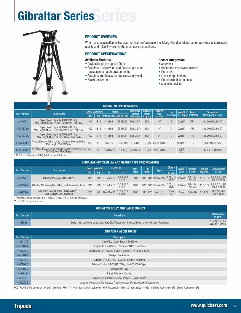
Tripods www.quickset.com
PRODUCT OveRvieW
When your application relies upon critical performance the Moog Gibraltar tripod series provides unsurpassed quality and reliability even in the most severe conditions.
PRODUCT sPeCifiCATiOns
Available features • Payload capacity up to 400 lbs• Anodized and powder coat finished parts for
resistance to harsh environments• Adapters and heads for any sensor payload• Rapid deployment
sensor integration • Antennas• Radar and microwave dishes• Cameras• Laser range finders• Communication antennas• Acoustic devices
GiBRALTAR sPeCifiCATiOns
Part Number DescriptionLoad Capacity Height Maximum
SpreadDiameter
ColumnTravel
in (cm)
ColumnO D
in (cm)
LegSections
Weightlbs (kg)
Feet(Foot Plate)
Dimensions (Transport) in (cm)lbs kg Max in (cm) Min in (cm)
4-60450-0 Tripod, Load Capacity 400 lbs/181 kg, Max Height 41 in/104 cm, 4 in/10 cm Foot Plate 400 181.8 41 (104) 25 (64.5) 55 (139.7) N/A N/A 2 22 (10) FP4 14 x 30.5 (33.5 x 77)
4-60450-0A Tripod, Load Capacity 400 lbs/181 kg, Max Height 41 in/104 cm, 6 in/15.2 cm Foot Plate 400 181.8 41 (104) 25 (64.5) 55 (139.7) N/A N/A 2 22 (10) FP6 14 x 30.5 (33.5 x 77)
4-60450-OD Tripod, Load Capacity 400 lbs/181 kg, Max Height 41 in/104 cm - Color: Olive Drab 400 181.8 41 (104) 25 (64.5) 55 (139.7) N/A N/A 2 22 (10) FP6 14 x 30.5 (33.5 x 77)
4-63020-8A * Tripod, Elevator Column, Load Capacity 200 lbs/90 kg, Max Height 85 in/215 cm 200 91 85 (216) 41.5 (105) 81 (205) 18 (45) 2.375 (6.03) 2 42 (19.1) FP6 17.5 x 49.5 (44x124)
4-63120-6A * 3/4 Tripod, Elevator Column, Load Capacity 200 lbs/90 kg, 65 in/165 cm Max. Height 200 91 65 (165.1) 31.5 (80) 65 (165.1) 18 (45) 2.375 (6.03) 2 33.5
(151) FP6 17.5 x 37 (44x93)
* All Column Diameters (O.D.) 2-3/8 inches/6.03 cm
GiBRALTAR HeADs, ReLAy AnD GeAReD TyPe sPeCifiCATiOns
Part Number DescriptionLoad Capacity L x W x H Pan
(deg)Tilt
(deg) TypeDimen-
sionin (cm)
ControlArm
CameraScrew
Weightlbs (kg)
Camera Platein (cm)lbs kg in cm
4-62050-6 Gibraltar Microwave Relay Head 330 149 6.5 x 6.5 x 7 16.5 x 16.5 x 17.8 360° 30° / 38° Spanner Nut 2.75 - 12
(6.8) Optional 0.5 - 13 Female 30 (13.6) 6.5 x 6.5 Fixed
(16.5 x 16.5)
4-62051-4 Gibraltar Microwave Relay Head, with heavy duty locks 330 149 6.5 x 6.5 x 7 16.5 x 16.5 x 17.8 360° 30° / 38° Spanner Nut 2.75 - 12
(6.8) Optional 0.5 - 13 Female 30 (13.6) 6.5 x 6.5 Fixed
(16.5 x 16.5)
4-62926-7 Instrument Geared Head, Calibrated AZ/EL, Load Capacity 200 lbs/90 kg 200 90 10 x 10 x 12 25.4 x 25.4
x 30.5 360° 53° / 67° Post O.D. 1.75 (4.37) None 3/8 - 16 21 (9.5) 8 x 10 Fixed
(20 x 25.4)
* Price does include control arm 4-65330-9, has 1/2-13 female receptacle. ** Has 3/8-16 camera screws.
GiBRALTAR DOLLy AnD CABLe GUARDs
Part Number Description Dimensions in (cm)
4-56021 Dolly, 4 inches/10 cm Wheels, for Herc/Gibr Tripods with 4 inches/10 cm or 6 in/15.2 cm Footplates 31 x 17.5 x 10.5 (78 x 44.5 x 26.6)
GiBRALTAR ACCessORies
Part Number Description
4-55110-7 Spike Tips (Set of 3) for 4-60450-0
4-55860-7 Adapter, to fit 4-60450-0 and accept Hercules Heads
4-65330-9 Control Arm for 4-62050-6 and 4-62051-4, 14 in/35 cm Long
4-65701-1 Wedge Plate Adapter
4-65740-9 Adapter, QTP 90, 130/150, 200, 500 to 4-60450-0
4-65850-6 Adapter to Mount 4-62926-7 Head to 4-60450-0 Tripod
4-65901-7 Wedge Plate Only
4-65911 Transit Adapter - Modified
4-69010-3 Adapter, fits Gibraltar Column, accepts Hercules Heads
4-69020-2 Adapter, Conversion, fits Hercules Tripods accepts Gibraltar Heads w/post mount
FOOT PLATE 6” (15.2cm) diam. w/ 5/8” spike hole - FP6”; 4” (10cm) diam. w/ 5/8” spike hole - FP4” Rubberball - Spike 1.5” diam. (3.8cm) - RBS1.5 Shovel Foot Small - SFS ; Shovel Foot Large - SFL
35
Gibraltar seriesGibraltar series

Tracking systems www.quickset.com
mULTi-fUnCTiOn UniT PROviDes THe fOLLOWinG CAPABiLiTies: • Precision video tracking (on switchable Visible or Thermal video signals) • AC-to-DC power converter for 24VDC @ 20 amps (max) for Pan/Tilt / Payload power • Video over IP for up to 4 video signals • IP control data interfacing to Quickset Pan/Tilt based surveillance nodes • Serial interface for: pan/tilt, visible camera, thermal imager, and other optional payloads
OPTiOnAL feATURes fOR mARiTime APPLiCATiOns:• Rugged Joysrick Controller: Splash proof joystick controller (dash-mount or handheld
models available)• Radar Slew-toCue: Automatically slews the camera to marine radar contacts (ARPA
targets).• Gyro Stabilization: 2-axis stabilization maintains a target in a 3 degree FOV image
while the host vessel undergoes up to +/- 20 degrees of pitch/roll motion and 360 degrees of yaw motion.
PAn/TiLT nODe inTeRfACeDC Output Power / video / serial Data Control Connector:• Mil – Spec Receptacle, 43 Socket,28 Shell -CT2-28-21-SS provides interfacing to
the following:– Dual NTSC / Pal input from video sensors. (switchable to provide tracking mode in
visible or thermal video)– Pan/Tilt Control (RS-422) – Individual camera (or other payload) serial data control (RS-422)
• 24VDC power for Pan/Tilt node operation• Control / Video Data Network Interface Mil-Spec RJ45 Receptacle for IP Control, Video
Data, and Video Tracking Communication to Control / Monitor site Local Video and Serial Connections Two local video server input (BNC) connections. Interface for local RS-422 control communication (Mil-Spec receptacle,15 socket, 14 Shell) Environmental
• Designed for IP-66 use• Temp Range: -15C to +55°C (Storage); -15C to +40C (Operating)
PRODUCT OveRvieW
We provide a multitude of advanced video tracking techniques designed to allow you to zoom in and precisely track distant boats, aircraft, vehicles or people. Examples of the tracking techniques include traditional contrast and correlation algorithms, and specially designed algorithms for tracking boats on the water and airplanes in the sky. In all cases, the objective is to zoom in and automatically follow the object of interest precisely.
36
Tracking systemsTracking systems
viDeO TRACKinG ALGORiTHms• Hottest Spot• Dynamic Centroid • Dynamic Correlation• Ground Vehicle / Boat Tracking• Ground to Air/Air to Ground Tracking
• Scene Lock • Threshold Tracking • Motion Tracking• Motion on Motion Tracking

Controllers and GUi www.quickset.com
PRODUCT OveRvieW
Moog offers a variety of controllers for analog and IC systems.
Analog Standard analog controllers are a cost-efficient solution for primarily AC and 115VDC powered analog pan and tilts. Low voltage DC solutions are also available.
QuickTrac ® Controllers are the versatile solutions from Moog for low voltage (12 and 24VDC) powered analog pan and tilts.
iC Unicom®-LT Controllers are the cost-efficient solution for primarily one-to-one pan and tilt and payload communicaton. If networked pan and tilt or system control is desirable, use the Unicom Controller.
AnALOG COnTROLLeRs sPeCifiCATiOns
Part Number Description Pan and Tilt Joystick Rack-mount Connector Voltage Input
Output Meters
DC AC Azimuth Elevation
12VDC Output
C124212 Controller, 12VDC/12VDC Prop. Speed, No Meters 20/50 Joystick 1/2 Rack 17 - Pin 12VDC 12 – – –
24VAC Output
C151111 Controller 115VAC/24VAC, Non-variable Spd. 20/90 Joystick Tabletop 17 - Pin 115 / 120VAC – 24
C173431 Controller 115-240VAC/24/120VAC, Non-variable Spd. ,Meters 200/500 Joystick Full 17 - Pin 120 / 240VAC – 24 / 120 X X
C162421 Controller 240VAC/115VAC, Non-variable Spd., A/Z Meters 90/130 Joystick Full 17 - Pin 240VAC – 115 X X
C173421 Controller 120-240VAC/24 / 120VAC, Non variable Spd.A/Z Meters 90/130 Joystick Full 17 - Pin 120 / 240VAC – 24 / 120 X X
115VDC Output
C167212 Controller 220-240VAC/115VDC, Prop Speed, No Meters 90/130 Joystick Plug 1/2 Rack 17 - Pin 220 - 240VDC 115 –
C157422 Controller 120VAC/115VDC, Prop Speed, A/Z Meters 90/130 Joystick Full 17 - Pin 120VDC 115 – X X
C167422 Controller 220-240VAC/115VDC, Prop Speed, A/Z Meters 90/130 Joystick Full 17 - Pin 220 - 240VDC 115 – X X
C167432 Controller 220-240VAC/115VDC, Prop Speed, A/Z Meters 200/500 Joystick Full 17 - Pin 220 - 240VDC 115 – X X
C177212 Controller 115/220-240VAC/115VDC, Prop Speed 200/500 Joystick 1/2 Rack 17 - Pin 115 / 220-240VDC 115 –
C177422 Controller 120VAC/115VDC, Prop Speed, A/Z Meters 90/130 Joystick Full 17 - Pin 115 / 220VDC 115 – X X
C177432 Controller 120VAC/115VDC, Prop Speed, A/Z Meters 200/500 Joystick Full 17 - Pin 115 / 220VDC 115 – X X
AnALOG PAn AnD TiLT TO COnTROLLeR CABLes sPeCifiCATiOns
Part Number Description Pan and TiltConnector Voltage (max)
Standard Lengths (in feet)Pan and Tilt Controller DC AC
6-19247-1.5 Cable, Analog, w/ 17 Socket / Pin Plugs, , 1.5ft. 20/50/90/130/200 17- Socket 17 - Pin 115 115 1.5, 10, 25, 100, 25, 100, 125, 150, 200, 250
37
Controllers and GUiControllers and GUi

Controllers and GUi www.quickset.com
QUiCK TRAC® COnTROLLeRs sPeCifiCATiOns
Part Number Description Pan and Tilt Joystick Rackmount Connector Voltage InputOutput Meters
DC AC Azimuth Elevation
12VDC Output
C102 Controller 12VDC/12VDC Prop Speed 20/50/90 Joystick Plug Full / 1/2 Rack 17 - Pin 12VDC 12 NA
C107 Controller 12VDC/12VDC Prop Speed A/Z Meters 20/50/90 Joystick Plug Full / 1/2 Rack 17 - Pin 12VDC 12 NA X X
C322 Controller 115VAC/12VDC Prop Speed 20/50/90 Joystick Plug Full / 1/2 Rack 17 - Pin 115VDC 12 NA
C327 Controller 115VAC/12VDC Prop Speed 20/50/90 Joystick Plug Full / 1/2 Rack 17 - Pin 115VDC 12 NA X X
C422 Controller 230VAC/12VDC Prop Speed 20/50/90 Joystick Plug Full / 1/2 Rack 17 - Pin 230VDC 12 NA
C427 Controller 230VAC/12VDC Prop Speed A/Z Meters 20/50/90 Joystick Plug Full / 1/2 Rack 17 - Pin 230VDC 12 NA X X
24VDC Output
C202 Controller 24VDC/24VDC Prop Speed 20/50/90/130 Joystick Plug Full / 1/2 Rack 17 - Pin 24VDC 24 NA
C207 Controller 24VDC/24VDC Prop Speed A/Z Meters 20/50/90/130 Joystick Plug Full / 1/2 Rack 17 - Pin 24VDC 24 NA X X
C207HT Controller 24VDC/24VDC Prop Speed A/Z Meters 20/50/90/130 Joystick Plug Full / 1/2 Rack 17 - Pin 24VDC 24 NA X X
C332 Controller 115VAC/24VDC Prop Speed 20/50/90/130 Joystick Plug Full / 1/2 Rack 17 - Pin 115VDC 24 NA
C337 Controller 115VAC/24VDC Prop Speed A/Z Meters 20/50/90/130 Joystick Plug Full / 1/2 Rack 17 - Pin 115VDC 24 NA X X
C337HT Controller 115VAC/24VDC Prop Speed A/Z Meters 20/50/90/130 Joystick Plug Full / 1/2 Rack 17 - Pin 115VDC 24 NA X X
C432 Controller 230VAC/24VDC Prop Speed 20/50/90/130 Joystick Plug Full / 1/2 Rack 17 - Pin 230VDC 24 NA
C437 Controller 230VAC/24VDC Prop Speed A/Z Meters 20/50/90/130 Joystick Plug Full / 1/2 Rack 17 - Pin 230VDC 24 NA X X
QUiCK TRAC® COnTROLLeRs ACCessORies
Part Number Description
CA100 Full Rack Kit
CA101 Half Rack Kit
CA102 Joystick Remote with 15 ft. Cable
CA102-30 Joystick Remote with 30 ft. Cable
CA112 Joystick Remote with 15 ft. Cable w/ Mil Spec Connector
iC COnTROLLeRs sPeCifiCATiOns
Part Number Description Control Interface Applicable Models Touchscreen Compatable
Unicom® LT
CLT-1000 CONTROLLER JOYSTICK - UNICOM LT RS-232, RS-422, RS-485 GeminEye, QPT- 20,50,90,200,500,QMP,QMP-R NO
CLT-1000R CONTROLLER JOYSTICK - UNICOM LT Ruggedized RS-232, RS-422, RS-485 GeminEye, QPT- 20,50,90,200,500,QMP,QMP-R NO
Unicom®
C-JCC-116-NL CONTROLLER JOYSTICK - UNICOM Ruggedized RS-232, RS-422, RS-485, IP (TCP-IP) GeminEye, QPT-20,50,90,200,500,QMP,QMP-R YES
GRAPHiCAL UseR inTeRfACe PRODUCT OveRvieW
When your applications require consolidated and versatile control, Moog provides a state-of-the-art Graphical User Interface for IC products. Highly customizable and expandable, our GUI provides remote access to positioners and camera feeds, with real-time operation and video feed at the convenience of a centralized location.
GUi sPeCifiCATiOns
Part Number Description
S-11000 QuickSet Graphical User Interface
38

Cables www.quickset.com
BifURCATeD - iC PAn AnD TiLT TO POWeR sUPPLy/viDeO COAx/COnTROLLeR CABLes sPeCifiCATiOns
Part Number Description
Bi - Universal - I QPT-20ICM and QPT-20ICMS (A-Control, B-Power) P/T Base Connector
6-BU132-150-25 150 ft control, 25 ft Power - Full 2-Port Universal - I Power /Control / Video (2) 32-Pin
6-BU132-150-50 150 ft control, 50 ft Power - Full 2-Port Universal - I Power /Control / Video (2) 32-Pin
6-BU132-150-75 150 ft control, 75 ft Power - Full 2-Port Universal - I Power /Control / Video (2) 32-Pin
6-BU132-100-100 100 ft control, 100 ft Power - Full 2-Port Universal - I Power /Control / Video (2) 32-Pin
6-BU132-150-150 150 ft control, 150 ft Power - Full 2-Port Universal - I Power /Control / Video (2) 32-Pin
Bi - Universal - II QPT-50, QPT-90, QMP / QMP-R, QPT-200 / 500 (A-Control, B-Power) P/T Base Connector
6-BU243-150-25 150 ft control, 25 ft Power - Full 4-Port Universal - II Power / Control / Video Coax (4) / AUX 43-Pin
6-BU243-150-50 150 ft control, 50 ft Power - Full 4-Port Universal - II Power / Control / Video Coax (4) / AUX 43-Pin
6-BU243-150-75 150 ft control, 75 ft Power - Full 4-Port Universal - II Power / Control / Video Coax (4) / AUX 43-Pin
6-BU243-100-100 100 ft control, 100 ft Power - Full 4-Port Universal - II Power / Control / Video Coax (4) / AUX 43-Pin
6-BU243-150-150 150 ft control, 150 ft Power - Full 4-Port Universal - II Power / Control / Video Coax (4) / AUX 43-Pin
Bi - Universal - II Lite Tilt A and Tilt B Ports for QPT-50, QPT-90, QMP / QMP-R, QPT-200 / 500 P/T Base Connector
6-BU2L4-150-25 150 ft control, 25 ft Power - Tilt - A and Tilt - B Power / Control / Video Coax (2). 43-Pin
6-BU2L4-150-50 150 ft control, 50 ft Power - Tilt - A and Tilt - B Power / Control / Video Coax (2). 43-Pin
6-BU2L4-150-75 150 ft control, 75 ft Power - Tilt - A and Tilt - B Power / Control / Video Coax (2). 43-Pin
6-BU2L4-100-100 100 ft control, 100 ft Power - Tilt - A and Tilt - B Power / Control / Video Coax (2). 43-Pin
6-BU2L4-150-150 150 ft control, 150 ft Power - Tilt - A and Tilt - B Power / Control / Video Coax (2). 43-Pin
PRODUCT OveRvieW
Moog provides a wide range of cable assemblies designed and produced to the same quality specifications as our other products. Common cables are listed below, please contact a Moog representative for special cable needs.
sinGLe enDeD (se) - iC PAn AnD TiLT TO POWeR sUPPLy/viDeO COAx/COnTROLLeR sPeCifiCATiOns
Part Number Standard Lengths (in feet)* Description
SE - Universal - I QPT-20 P/T Base Connector
6-SU132 6, 25, 50, 75, 100, 150 Full 2-Port Universal - I Power /Control / Video Coax (2) 32-Pin
SE - Universal - II QPT-50, QPT-90, QMP / QMP-R, QPT-200 / 500 (4 - Port) P/T Base Connector
6-SU243 6, 50, 75, 100, 150 Full 4-Port Universal - II Power / Control / Video Coax (4) / AUX 43-Pin
SE - Universal - II Lite QPT-50, QPT-90, QMP / QMP-R, QPT-200 / 500 (Tilt A) P/T Base Connector
6-SU2L4 6, 25, 50, 75, 100, 150 Tilt - A and Tilt - B Power / Control / Video Coax (2). 43-Pin
Universal Port Universal Port to Payload Cables P/T Base Connector
6-19269 2 Port A to 16 Shell, 26 - Socket Right Angle –
6-19193 2 Port D to 20 Shell, 55 Socket Right Angle –
Outdoor Power Supplies For all Outdoor Power Supplies; Terminated with NEMA 5-15P (Standard 3- Pin Wall Plug), and Mil Spec P/T Base Connector
6-19235-16 16, 50, 100, 300 Cable, Input Power, 115VAC –
AnALOG PAn AnD TiLT TO COnTROLLeR CABLes sPeCifiCATiOns
Part Number Standard Lengths (in feet) Description Pan and TiltConnector Voltage (max)
Pan and Tilt Controller DC AC
6-19247 1.5, 10, 25, 100, 125, 200, 250 Cable, Analog, w/ 17 Socket / Pin Plugs 20/50/90/130/200 17- Socket 17 - Pin 115 115
39
CablesCables

sensor and surveillance systems3650 Woodhead Drive | Northbrook, IL 60062-1895 USA | +1.847.498.0700 | Fax: +1.847.498.1258 | www.quickset.com
LOCATiOns
Argentina
Australia
Austria
Brazil
Canada
China
Finland
France
Germany
India
Ireland
Italy
Japan
Luxembourg
Netherlands
Norway
Philippines
Russia
Singapore
South Africa
South Korea
Spain
Sweden
Switzerland
United Arab Emirates
United Kingdom
United States
Form 500-700 090413
© 2013 Moog, Inc . A l l r i gh ts reser ved .Produc t and company names l i s ted a re t rademarks o r t rade names o f the i r respec t i ve compan ies .Pe lco i s a reg is te red t rademark o f Pe lco , Inc .