Quick Start Guide gecatalog.weg.net/files/wegnet/WEG-ssw-04-quick-start-guide-qs006... · Quick...
8
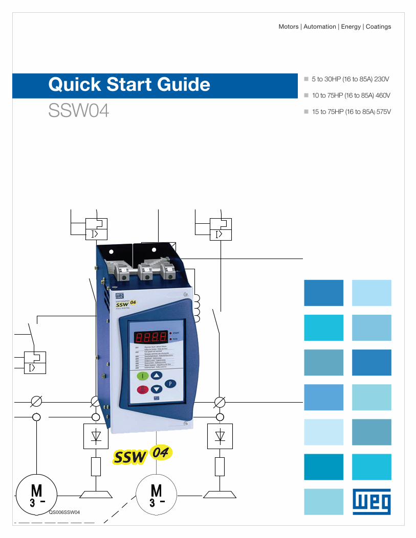
Quick Start Guide SSW04 g 5 to 30HP (16 to 85A) 230V g 10 to 75HP (16 to 85A) 460V g 15 to 75HP (16 to 85A) 575V Motors | Automation | Energy | Coatings QS006SSW04
Transcript of Quick Start Guide gecatalog.weg.net/files/wegnet/WEG-ssw-04-quick-start-guide-qs006... · Quick...
Quick Start GuideSSW04
g 5to30HP(16to85A)230V
g 10to75HP(16to85A)460V
g 15to75HP(16to85A)575V
Motors | Automation | Energy | Coatings
QS006SSW04

Power Connections and Keypad Operation:
2
LED Display –indicates faultcodes, status,parameter numberand value.
Power Connections and Keypad Operation:
The SSW04 Quick Start Guide is a supplement to help get the SSW04 started quickly using the most common installationand configuration options. This SSW04 Quick Start Guide is not meant to replace the SSW04 User’s Manual. For detailedinstructions, safety precautions, proper mounting, installation, configuration, and operation please refer to the SSW04User’s Guide. Warning: Only qualified personnel should plan or implement the installation, start-up, operation andmaintenance of this equipment. Personnel must read the entire SSW04 User’s Guide before attempting to install, operateor troubleshoot the SSW04.
Figure 1 - Power and Grounding Connections
Figure 2 – Keypad Operation
Key Description
Switches the display between
parameter number and content.
Increases Parameternumber/content.
Decreases Parameternumber/content.
Starts (Enables) the motor.
Stops (Disables) the motor, andresets the Soft Starter after a fault
has occurred.
Display Description
rdy Soft Starter is ready to be enabled
Pup Loading pump control parameters
EEP Loading “Default” values
on Function enabled
oFF Function disabled
Start - Red LED
Run - Red LED

Basic Wiring:
3
Basic Wiring:
1. Mount the SSW04 to a flat vertical surface.2. Connect the three-phase incoming power leads to the R, S, and T connections on the power terminal and connect
the GROUND lead to PE on the chassis (Refer to Figure 1). Connect the motor leads to the U, V, and Wconnections on the power terminal and connect the GROUND lead to PE on the chassis (Refer to Figure 1).Note: Only three-phase AC motors can be used.
3. Connect control power (110Vac) hot and neutral leads to pins 1 & 2 of the X1 connector respectively.4. Apply Control Power followed by Input Power. The soft starter will run self-diagnostics and if no problems are
found it will display “rdy” on the LED display.
Minimum Parameters to Set:
P21 – Motor Current Setting - Factory default position is “OFF” so there is no motor overload protection. To protect themotor from overload, obtain the full load amperage (FLA) off the motor and soft-starter name plates, and using thefollowing formula, calculate the percentage of current that the motor will draw from the soft-starter.
– IN of the soft-starter = 170A– IN of the motor = 140A– IN of the motor / IN of the switch = 140A / 170A = 0.823– P21 = 82.3%
P25 – Thermal Class of Overload Protection - Set to factory default of 30 if not specified on the motor name plate.
P26 – Motor Service Factor – obtain from motor name plate.
Notes: (1) To change the value of parameters set parameter P000=ON.(2) Soft Starters are shipped with factory default values. If parameters have been changed it is advisable to reset tofactory default values prior to a new installation by setting P46=ON.(3) These are the minimum parameters for a perfect adaptation between soft starter and motor. For a completedescription of Parameters and Error codes refer to Chapters 6 and 7 in the SSW04 User’s Guide.
Keypad Start/Stop Operation (Local Mode):
Action LED Display Description
After power-up, the display shows thefollowing message.
Soft Starter powered-up.
Press “Start”Motor begins to accelerate.Motor current (P72) = 200%
When end of Acceleration ramp (P02) isreached the Motor Current (P72) = 100%
Press “Stop”
By default, motor coasts to rest. For adecelerated stop, program P04 for desireddeceleration time.
Soft Starter is turned off in “rdY” condition.
Start/Run LED Symbols:
Start-up by Voltage Ramp
4
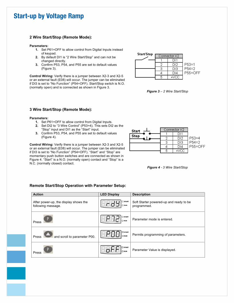
2 Wire Start/Stop (Remote Mode):
Parameters:1. Set P61=OFF to allow control from Digital Inputs instead
of keypad.2. By default DI1 is “2 Wire Start/Stop” and can not be
changed directly.3. Confirm P53, P54, and P55 are set to default values
(Figure 3).
Control Wiring: Verify there is a jumper between X2-3 and X2-5or an external fault (E08) will occur. The jumper can be eliminatedif DI3 is set to “No Function” (P54=OFF). Start/Stop switch is N.O.(normally open) and is connected as shown in Figure 3.
Figure 3 – 2 Wire Start/Stop
3 Wire Start/Stop (Remote Mode):
Parameters:1. Set P61=OFF to allow control from Digital Inputs.2. Set DI2 to “3 Wire Control” (P53=4). This sets DI2 as the
“Stop” input and DI1 as the “Start” input.3. Confirm P53, P54, and P55 are set to default values
(Figure 4).
Control Wiring: Verify there is a jumper between X2-3 and X2-5or an external fault (E08) will occur. The jumper can be eliminatedif DI3 is set to “No Function” (P54=OFF). “Start” and “Stop” aremomentary push button switches and are connected as shown inFigure 4. “Start” is a N.O. (normally open) contact and “Stop” is aN.C. (normally closed) contact.
Figure 4 - 3 Wire Start/Stop
Remote Start/Stop Operation with Parameter Setup:
Action LED Display Description
After power-up, the display shows thefollowing message.
Soft Starter powered-up and ready to beprogrammed.
PressParameter mode is entered.
Press and scroll to parameter P00.Permits programming of parameters.
PressParameter Value is displayed.

5
Press
Setting P00=ON allows parameters to beprogrammed.
PressParameter value is stored.
Press and scroll to parameter P61.
Parameter P61 determines whether commandsare accepted through keypad/serial port orthrough the digital inputs.
PressParameter Value is displayed.
Press
Setting Parameter P61 to “OFF” allowscommands to be accepted through digital inputsinstead of keypad/serial port.
PressParameter value is stored.
Press and scroll to parameter P72Indicates percentage of output current.
Press Parameter Value is displayed.
A. Close the Start/Stop switch at DI1 if 2Wire Control.
B. Push the Start switch at DI1 if 3 WireControl.
Motor starts and P72 indicates 200% outputcurrent at start up.
After acceleration time (P02) has been reachedP72 indicates 100% output current.
A. Open Start/Stop switch at DI1 if 2 WireControl.
B. Push the Stop switch at DI2 if 3 WireControl.
Motor coast to rest if P04 is set to “OFF”. For adecelerated stop, program P04 for desireddeceleration time.
Soft Starter is turned off in “RDY” condition.
Start/Run LED Symbols:
Fault Codes:
When a fault is detected, the soft starter is disabled and the Fault Code is displayed (example E03). To restart the softstarter after a fault has occurred, the soft starter must be reset. Resetting the soft starter can be done by disconnectingand reapplying AC power (power-on reset), by pressing the “O/RESET” key (manual reset), automatic reset, or via digitalinputs. For details on Reset and a full list and description of Fault Codes please read Chapter 7 in the SSW04 User’sGuide.
Credit Limiting for Loads with High or Constant Starting Torque
6
Current Limiting for Loads with High or Constant Starting Torque:
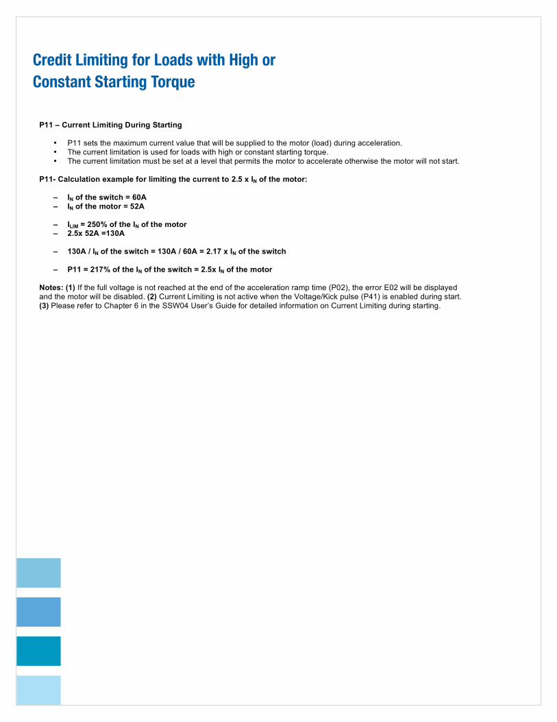
P11 – Current Limiting During Starting
• P11 sets the maximum current value that will be supplied to the motor (load) during acceleration.• The current limitation is used for loads with high or constant starting torque.• The current limitation must be set at a level that permits the motor to accelerate otherwise the motor will not start.
P11- Calculation example for limiting the current to 2.5 x IN of the motor:
– IN of the switch = 60A– IN of the motor = 52A
– ILIM = 250% of the IN of the motor– 2.5x 52A =130A
– 130A / IN of the switch = 130A / 60A = 2.17 x IN of the switch
– P11 = 217% of the IN of the switch = 2.5x IN of the motor
Notes: (1) If the full voltage is not reached at the end of the acceleration ramp time (P02), the error E02 will be displayedand the motor will be disabled. (2) Current Limiting is not active when the Voltage/Kick pulse (P41) is enabled during start.(3) Please refer to Chapter 6 in the SSW04 User’s Guide for detailed information on Current Limiting during starting.

SoftStarters
SSW04Technical Data
Power Supply Voltage Model D: 220 / 230 / 240 / 380 / 400 / 415 / 440 V ( + 10 % , - 15 % )Model G: 460 / 480 / 575 V ( + 10 % , - 15 % )
Frequency 50 / 60 Hz +/- 5 Hz ( 45 ... 65 Hz )Control Voltage 115VAC
Enclosure Metallic Cabinet IP 20 Color Cover: Opaque Gray, Cabinet: Opaque Blue
Control Method Motor Voltage VariationPower Supply Switched Mode Power SupplyCPU 16 Bit Microprocessor
Starting Duty Cycle 300 % ( 3 x Rated Current ) for 20 sec (10 Starts/hour)(10 Starts / Hr)Inputs Digital 4 x 24vDC Programmable Isolated InputsOutputs Relay 2 programmable Outputs: 250 V / 1 A Form A Contact (NO)
Analog 1 Output ( Reversing (NO + NC ) : 250 V / 1 A – Fault IndicationCommunication Serial Interface RS-232Safety Protections Power supply phase loss Programming Error
Motor Phase Loss Motor locked rotorMotor Overload - i2t CPU Error (Watchdog)External Fault Motor Immediate Over CurrentPhase Sequence Motor Over Temperature (via Thermistor input)Motor Immediate Under Current Self Diagnosis ErrorThyristor Fault Thyristor’s / Heatsink Over TemperatureSerial Communication Error
Functions / Features Standard Built-in Operator Interface ( keypad ) Detachable – 7 Segment LED DisplayProgramming Enabling PasswordFault Auto-DiagnosisPUMP CONTROL Feature ( Water Hammer Protection for Pumps )ENERGY SAVING FeatureBY-PASS RelayFWD / REV Feature via Digital Input ( Needs External Contactor)RS-232 Serial InterfaceMotor PTC thermistor inputProgrammable Pedestal Voltage 25 … 90% of Rated VoltageProgrammable Acceleration Ramp 1 ... 240 secondsProgrammable Deceleration Ramp OFF, 2 ... 240 secondsProgrammable Step Down Voltage for Deceleration 100 ... 40 % of Rated VoltageProgrammable Starting Current Limit OFF, 150 ... 500 % of Rated CurrentProgrammable Immediate Motor Over Current Level 105 ... 200 % of Rated CurrentProgrammable Immediate Over Current Time OFF, 1 ... 20 secondsProgrammable Immediate Motor Under Current Level 25 ... 95 % of Rated CurrentProgrammable Immediate Under Current Time OFF, 1 ... 30 secondsKick Start Level : 70 ... 90 % of Rated Voltage
Duration: 0.1 ... 2 secondsDC Braking ( DC Current Injection ) Level : 30 ... 50 % of Rated Voltage
Duration: 1 ... 10 secondsProgrammable Motor Overload Protection OFF, 50 ... 120 % of Rated CurrentJOG Function 25 ... 50 % of Rated VoltageProgrammable Fault Auto Reset OFF, 10 ... 600 secondsProgrammable Motor Thermal Memory Auto-Reset OFF, 1 ... 600 secondsMotor Thermal Overload Protection Class 5, 10, 15, 20, 25 and 30Motor Service Factor 0.80 ... 1.50Programmable Line Voltage 220 ... 440 V and 460 ... 575 V
Optional Remote Operator Interface ( LED’s )
Operator Interface Programming / Start, Stop / Reset and Programming(Keypad) Commands Increment and Decrement Parameters Content
Display Readings Output Current ( Motor ) – [ A ] Output Voltage – [ 0...100 % Rated Voltage ]Output Current ( Motor ) – [ % of Rated ] Motor Output Factor – [ 0.00 ... 0.99 ]Load Active Power – [ kW ] 4 Last Faults Back-upLoad Apparent Power – [ kVA ] Soft Starter Software VersionThermal Protection Status – [ 0 ... 250 % ]
Ambient Temperature 0 ... 40 °C ( 32 ... 104 °F ) Standard Operation at Rated Current40 ... 55 °C ( 104 ... 131 °F ) With Output Current Derating
Humidity 0 ... 90 %, Non CondensingAltitude 0 ... 1000 m ( 3,300 ft ) Standard Operation at Rated Current
Up to 4000 m ( 13,200 ft ) – With Current Derating (1%/100 m(328 ft) above 1000 m (13,200 ft) )Finishing Color Cover: Light Grey RAL 7032 Cabinet: Dark Grey RAL 7022Conformities Safety UL 508 Standard – Industrial Control Equipment
Low Voltage EN 60947-4-2 Standard ; LVD 73 / 23 / EEC – Low Voltage DirectiveEMC EMC Directive 89 / 336 / EEC – Industrial Environment With Additional Filter
Certifications UL(USA)/cUL(Canada) Underwriters Laboratories Inc. – USACE ( Europe ) Certified by ITS – UK

WEG Electric Corp.1327 Northbrook Parkway, Suite 490Suwanee, GA 30024Phone: 1-800-ASK-4WEG web: www.weg.net
QS006SSW04