Quick Installation Manual - Amazon S3
16
Quick Installation Manual eSTORE-BAT-10.3P with ES5048 / EM5048
Transcript of Quick Installation Manual - Amazon S3
Quick Installation Manual
eSTORE-BAT-10.3P with ES5048 / EM5048

Step1 Step2
Open the battery packaging.
Step3
Fix the battery to the wall with M8*60 screws.
Fix the bracket onto the battery with M5*10 screws.
M5*10 screws M6 Gasket M8*60 Expansion screw
Open The Package
Step4
Take the Cable box out of packaging and remove the front panel.
Step5
Take the inverter and accessories out of packaging.
01

02
Step7Step6
and make marks for drilling.Drilling holes accordingly(φ8*80mm)
Note: Opening size drawing
8*80

03
Step8 Step9Hang on the inverter.Fix the bracket with expansionscrews
, 5mm screw driver and gasket.
Step11
Install the Wi-Fi module and secure it with 2 x M5*10 screws.
Install the Wi-Fi Module
Step10
Note: Wi-Fi module should be installed on the left side of the inverter bracket.

04
Step12
DIP Switch and Connect Communication Cable
Use a screwdriver to remove the right communication panel.
Step14
Fix the connector of the cable box power cable to the inverter with 2 x M8*12 screws.
Connecting The Power Cable
Step13
The battery DIP switch is configured according to the black mark position as shown in the above figure. Switch 2 & 3 should be up and the rest are all down.
Note: Make sure the power cable passes through the cable gland and the terminal color matches. Fix with 4 x M3*8 screws.
Step16
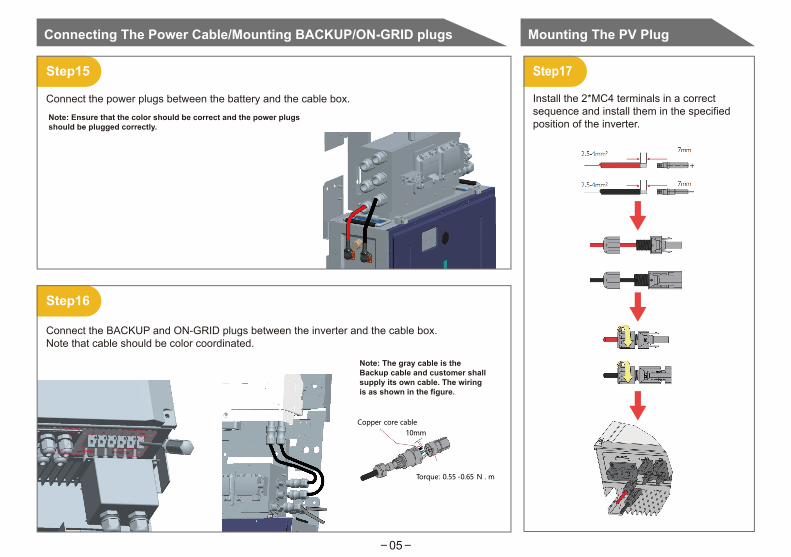
Step17
Install the 2*MC4 terminals in a correct sequence and install them in the specified position of the inverter.
Mounting The PV Plug
Step15
Connect the power plugs between the battery and the cable box.
Connect the BACKUP and ON-GRID plugs between the inverter and the cable box.Note that cable should be color coordinated.
Note: Ensure that the color should be correct and the power plugs should be plugged correctly.
Note: The gray cable is the Backup cable and customer shall supply its own cable. The wiring is as shown in the figure.
Copper core cable
Torque: 0.55 -0.65 N . m
10mm
Connecting The Power Cable/Mounting BACKUP/ON-GRID plugs
05
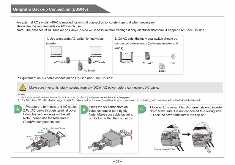
An external AC switch (≥40A) is needed for on-grid connection to isolate from grid when necessary.Below are the requirements on AC switch use:Note: The absence of AC breaker on Back-Up side will lead to inverter damage if only electrical short-circuit happend on Back-Up side.
1. Use a separate AC switch for individualinverter
AC Switch AC Switch
AC Switch
2. On AC side, the individual switch should beconnected before loads (between inverter andloads)
Loads
AC Switch Grid
• Equirement on AC cable connected on On-Grid and Back-Up side:
Make sure inverter is totally isolated from any DC or AC power before connectiong AC cable.
NOTE:1. Neutral cable shall be blue, line cable black or brown (preferred) and protective earth cable yellow-green.2. For AC cables, PE cable shall be longer than N & L cables, so that if in any case AC cable slips or taken out, the protecting earth conductor will be the last to take the strain
CableScrew Cap
Single holeseal ring
TheInsulator
AC Cover Connection Terminal
Fastening torsion 2-2.5N.m
1.Prepare the terminals and AC cables2.Put AC cable through terminal coverfollow the sequence as on the leftNote: Please use the terminals inGoodWe components box
Press the six connectors on cable conductor core tightlyNote: Make sure cable jacket is not locked within the connector
1.Connect the assambled AC terminals onto inverterNote: Make sure it is not connected to a wrong side2. Lock the cover and screw the cap on
A B C
On-grid & Back-up Connection (ES5048)
06

Special Adjustable SettingsThe inverter has field adjustable setting like tripping point, tripping time, reconnect time, active and invalid of QU/PU curves etc. by special firmware. Please contact GoodWe after-sales for the special firmware and adjust methods.
Declaration For Back-Up LoadsGoodWe ES inverter is able to supply a continuous 4600VA output or max 6900VA in less than 10 seconds on Back-Up side to support backup loads. And the inverter has self-protection derating at high ambient temperature.
Accepted loads as below:• Inductive Load: Max 1.5KVA for single inductive load, max 2.5KVA for total inductive load power• Capacitive load: Total capacitive load (like computer, switch power etc.) power ≤3.0KVA (Any load with high inrush current at start-up is notaccepted)
Back-up
Loads Grid
On-grid123
SP3T
1:Load is supplied from Back-Up side2:Load is isolated
3:Load is supplied from grid sideFor a convenient maintenance, an SP3T switch could be installed on Back-Up and On-Grid side. Then it is adjustable to support load by Back-Up or by grid or just leave it there
Declaration For Back-Up Overload ProtectionInverter will restart itself as overload protection happens. The preparation time for restarting will be longer and longer (max one hour) if overload protection repeats. Take following steps to restart inverter immediately:• Decrease Back-Up load power within max limitation• On PV Master→Advanced Setting→ Click “Reset Back-Up Overload History”
07
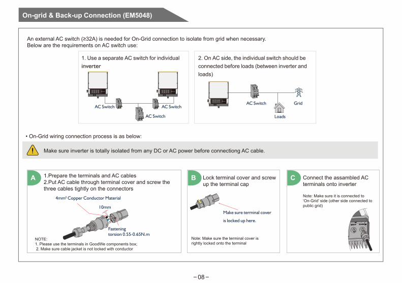
On-grid & Back-up Connection (EM5048)
An external AC switch (≥32A) is needed for On-Grid connection to isolate from grid when necessary.Below are the requirements on AC switch use:
A
1. Use a separate AC switch for individualinverter
2. On AC side, the individual switch should beconnected before loads (between inverter andloads)
Loads
AC Switch GridAC Switch AC Switch
AC Switch
• On-Grid wiring connection process is as below:
Make sure inverter is totally isolated from any DC or AC power before connectiong AC cable.
Make sure terminal cover
is locked up here.
10mm
4mm2 Copper Conductor Material
Fastening torsion 0.55-0.65N.m
1.Prepare the terminals and AC cables2.Put AC cable through terminal cover and screw thethree cables tightly on the connectors
NOTE:1. Please use the terminals in GoodWe components box;2. Make sure cable jacket is not locked with conductor
B
Note: Make sure the terminal cover is rightly locked onto the terminal
08
C Connect the assambled ACterminals onto inverter
Note: Make sure it is connected to ‘On-Grid’ side (other side connected to public grid)
Lock terminal cover and screw up the terminal cap

Special Adjustable SettingsThe inverter has field adjustable setting like tripping point, tripping time, reconnect time, active and invalid of QU/PU curves etc. by special firmware. Please contact GoodWe after-sales for the special firmware and adjust methods.
Connection for SPLIT Grid SystemIn SPLIT grid system, there is a solution to allow inverter work under on-grid condition (Pic 20). But the export power and load power might be detected inaccurately as the nominal output power of inverter is 230V and there could be loads of 110V or 220V
• Back-Up wiring connection process is as below:An external AC switch (≥32A) is needed for Back-Up connection to be isolated when necessary.Note: The absence of AC breaker on Back-Up side will lead to inverter damage if only electrical short-circuit happend on Back-Up side. AndBack-Up funtion cannot turn off under on-grid condition.
A B C
Make sure terminal cover
is locked up here.
10mm
4mm2 Copper Conductor Material
Fastening torsion 0.55-0.65N.m
1.Prepare the terminals and AC cables2.Put AC cable through terminal cover and screw thethree cables tightly on the connectors
NOTE: 1. Please use the terminals in GoodWe components box;2. Make sure cable jacket is not locked with conductor
Lock terminal cover and screw up the terminal cap
Note: Make sure the terminal cover is rightly locked onto the terminal
Connect the assambled AC terminals onto inverter
Note: Make sure it is connected to ‘Back-Up’ side (other side connected to public grid)
09

10m
Smart Meter
Hou
seHouse→Grid
CT
N
L1
L3L2
1 4
Make sure AC cable is totally isolated from AC power before connecting Smart Meter and CT
The Smart Meter with CT in GoodWe product box is compulsory for ES system installation, used to detect grid voltage and current direction and magnitude, further to instruct the operation condition of ES inverter via RS485 communication.
NOTE: 1. The Smart Meter and CT is well configured, please do not change any setting on Smart Meter;2. One Smart Meter& CT can only be used for one ES inverter;3. CT must be connected on the same phase with Smart Meter power cable
• Smart Meter & CT Connection Diagram
ES5048
EM5048
Smart Meter
Smart meter & CT Connection
10
11
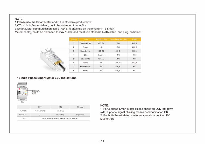
NOTE: 1.Please use the Smart Meter and CT in GoodWe product box;2.CT cable is 3m as default, could be extended to max 5m3.Smart Meter communication cable (RJ45) is attached on the inverter (“To SmartMeter” cable), could be extended to max 100m, and must use standard RJ45 cable and plug, as below:
Orange NC NC
Orange&white 485_A2 NC
Green&white 485_B2 485_B1
Blue CAN_H NC
Blue&white CAN_L NC
Green NC 485_A1
Brown&white NC 485_B1
Brown
2
1
3
4
5
6
7
8 NC 485_A1
RS485
485_B
485_A
485_A
NC
NC
485_B
NC
NC
• Single-Phase Smart Meter LED Indications
NOTE:1. For 3-phase Smart Meter please check on LCD left-downside, a phone signal blinking means communication OK2. For both Smart Meter, customer can also check on PVMaster App
05OFF Blinking
ENERGY / Exporting
POWER Not
working /
COM
ON
Importing
Working
ENERGYPOWERCOM
Blink one time when it transfer data to inverter
Smart Meter FunctionBMS FunctionColorPosition

Wi-Fi Configuration
Step20
PC:
12
13

14
PV Master is an external applica�on for GoodWe storage inverters to configure inverters or to do Wi-Fi configura�on, used on smart phone for both Android and iOS system, main func�on of PV Master App as below:
1. Edit system configura�on to make the system work as it is required locally onsite.
2.
Wi-Fi configura�on
The following pages will introduce the usage of PV Master App on GoodWe hybrid inverters. Any opera�on on the App for the system please follow this instruc�on. Any confusion on this introduc�on, please contact GoodWe for explana�on.
BRIEF INTRODUCTION
PV Master is used on both iOS and Android system, customers need install this app on your device before using it.
For Android system: Download Pla�orm: Google Play Search Keywords: PV Master Compa�ble System: Android
For iOS system: Download Pla�orm: App Store Search Keywords: PV Master Compa�ble System: iOS 8.0 or higher version for iPhone/iPad/iPod Touch
1. Parameters Configura�on --- Local Configura�on
Local configura�on means do inverter configura�on by op�onal two ways:
a. Connec�ng Solar-WiFi* from inverter directly to your smart phone or pad (pic 1): Wi-Fi name: “Solar-WiFi*” (* means the last 8 characters of inverter serial No. ) Password: 12345678
Android System iOS System
INTERFACE INTRODUCTION
a. b. Connect your smart phone to the same network your inverter configured to (a�er Wi-Fi configura�on) refer to Pic 2
Click here to choose the hybrid inverter you want to configure
APP:

Alpha ESS Co., Ltd.
Australia: Alpha ESS Australia Pty. Ltd.+61 (0) 402 500 520 (Sales)+61 1300 968 933 (Technical Support)[email protected]
www.alpha-ess.com.au Suite 1, Level 1, 530 Botany Road, Alexandria, NSW, 2015