Quick Installation Guide -...
12
Wi-Fi Array™ 812-0004-001A Quick Installation Guide This Guide covers the steps required to install the Xirrus XN16 or XN8 Wi-Fi Array on a T-bar ceiling and execute the initial power up of the Array. If installing the Array with a wall bracket (XS-BKT-WALL-3900-3700), indoor enclosure (XE-2020), or outdoor enclosure (XE-4000,OUT), refer to the accompanying Quick Installation Guide shipped with those products. Product specifications start on page 9. For additional information and advanced installation instructions, see the Wi-Fi Array User’s Guide (part number 800-0006-001). You Need the Following Items: w Wi-Fi Array Accessory Kit (included in the Wi-Fi Array shipping carton). w Optional serial console cable (included). Cable lengths up to 25’ are supported, per the RS-232 specification w Dedicated AC power source adjacent to each unit, or remote AC outlet(s) if using the optional Xirrus Power over Gigabit Ethernet (PoGE) single port or eight port modules. If using PoGE, the Array must be connected to PoGE networks without routing cabling to the outside plant—this ensures that cabling is not exposed to lightning strikes or possible cross over from high voltage lines. w Copper Ethernet connection(s) to your wired network. w Workstation with a Web browser to configure the Wi-Fi Array. w Flat screwdriver and 7/16” nut driver for attaching the T-bar clips to the ceiling grid. w Knife for cutting an access hole in the ceiling tile. Choose a Suitable Location w The best location is ceiling-mounted within an open plan environment. w Choose a location that is central to your users. Refer to the Wi-Fi Array User’s Guide for placement details—part number 800-0006-001. w Keep the unit away from electrical devices or appliances that generate RF noise—at least 3 to 6 feet (1 to 2 meters). w Maintain a distance of 50 feet between additional Wi-Fi Arrays. 1 2
Transcript of Quick Installation Guide -...
Wi-Fi Array™
Quick Installation GuideThis Guide covers the steps required to install the Xirrus XN16 or XN8 Wi-Fi Array on a T-bar ceiling and execute the initial power up of the Array. If installing the Array with a wall bracket (XS-BKT-WALL-3900-3700), indoor enclosure (XE-2020), or outdoor enclosure (XE-4000,OUT), refer to the accompanying Quick Installation Guide shipped with those products.
Product specifications start on page 9. For additional information and advanced installation instructions, see the Wi-Fi Array User’s Guide (part number 800-0006-001).
You Need the Following Items:w Wi-Fi Array Accessory Kit (included in the Wi-Fi Array shipping carton).
w Optional serial console cable (included). Cable lengths up to 25’ are supported, per the RS-232 specification
w Dedicated AC power source adjacent to each unit, or remote AC outlet(s) if using the optional Xirrus Power over Gigabit Ethernet (PoGE) single port or eight port modules.
If using PoGE, the Array must be connected to PoGE networks without routing cabling to the outside plant—this ensures that cabling is not exposed to lightning strikes or possible cross over from high voltage lines.
w Copper Ethernet connection(s) to your wired network.
w Workstation with a Web browser to configure the Wi-Fi Array.
w Flat screwdriver and 7/16” nut driver for attaching the T-bar clips to the ceiling grid.
w Knife for cutting an access hole in the ceiling tile.
Choose a Suitable Locationw The best location is ceiling-mounted within an open plan environment.
w Choose a location that is central to your users. Refer to the Wi-Fi Array User’s Guide for placement details—part number 800-0006-001.
w Keep the unit away from electrical devices or appliances that generate RF noise—at least 3 to 6 feet (1 to 2 meters).
w Maintain a distance of 50 feet between additional Wi-Fi Arrays.
1
2
812-0004-001A
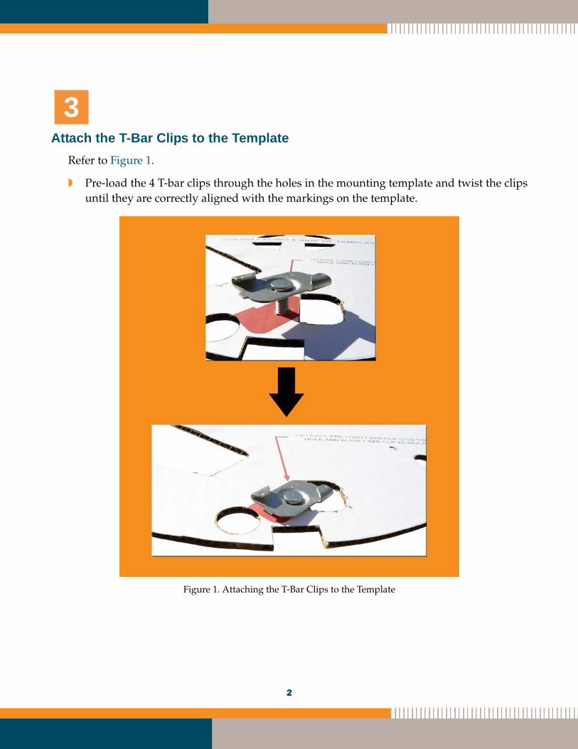
Attach the T-Bar Clips to the TemplateRefer to Figure 1.
w Pre-load the 4 T-bar clips through the holes in the mounting template and twist the clips until they are correctly aligned with the markings on the template.
Figure 1. Attaching the T-Bar Clips to the Template
3
2
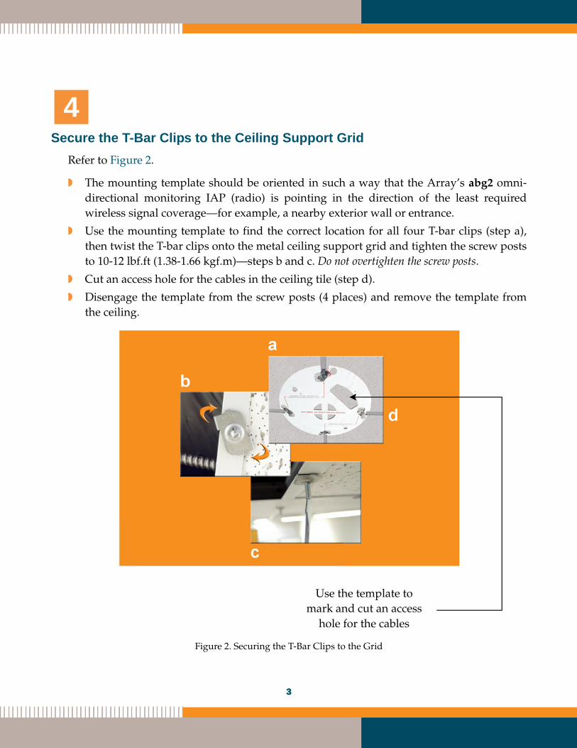
Secure the T-Bar Clips to the Ceiling Support GridRefer to Figure 2.
w The mounting template should be oriented in such a way that the Array’s abg2 omni-directional monitoring IAP (radio) is pointing in the direction of the least required wireless signal coverage—for example, a nearby exterior wall or entrance.
w Use the mounting template to find the correct location for all four T-bar clips (step a), then twist the T-bar clips onto the metal ceiling support grid and tighten the screw posts to 10-12 lbf.ft (1.38-1.66 kgf.m)—steps b and c. Do not overtighten the screw posts.
w Cut an access hole for the cables in the ceiling tile (step d).
w Disengage the template from the screw posts (4 places) and remove the template from the ceiling.
Figure 2. Securing the T-Bar Clips to the Grid
4
Use the template to mark and cut an access
hole for the cables
3
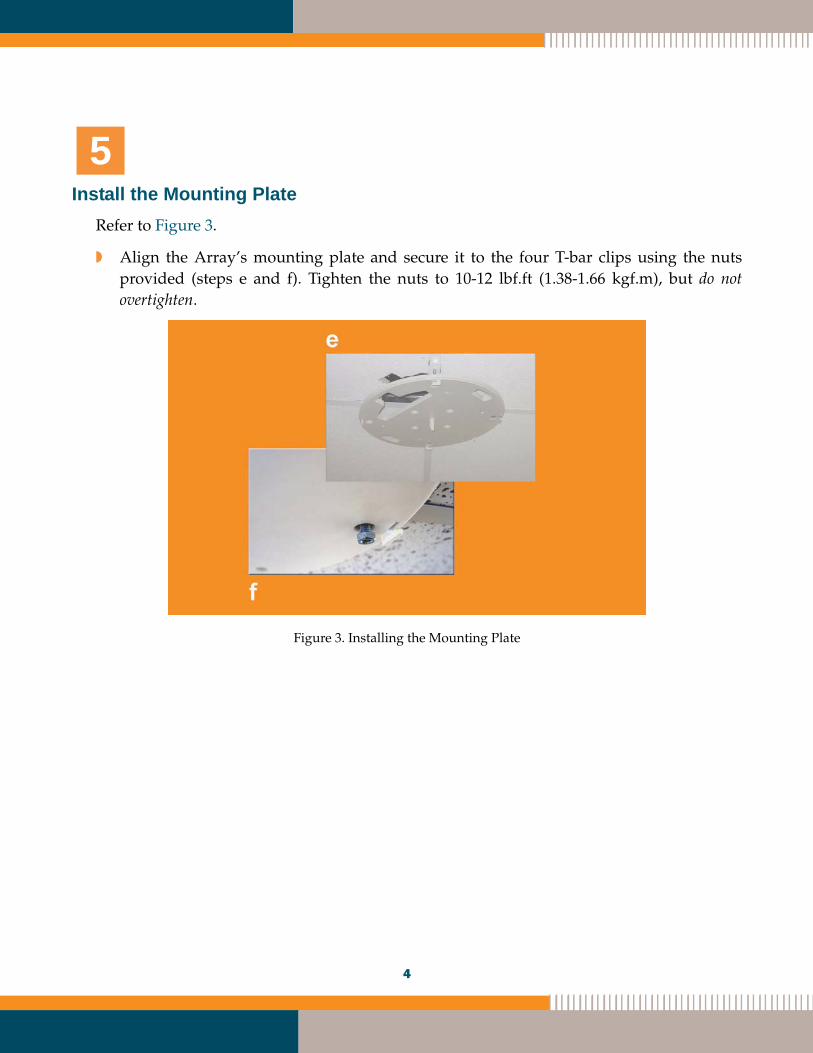
Install the Mounting PlateRefer to Figure 3.
w Align the Array’s mounting plate and secure it to the four T-bar clips using the nuts provided (steps e and f). Tighten the nuts to 10-12 lbf.ft (1.38-1.66 kgf.m), but do not overtighten.
Figure 3. Installing the Mounting Plate
5
4
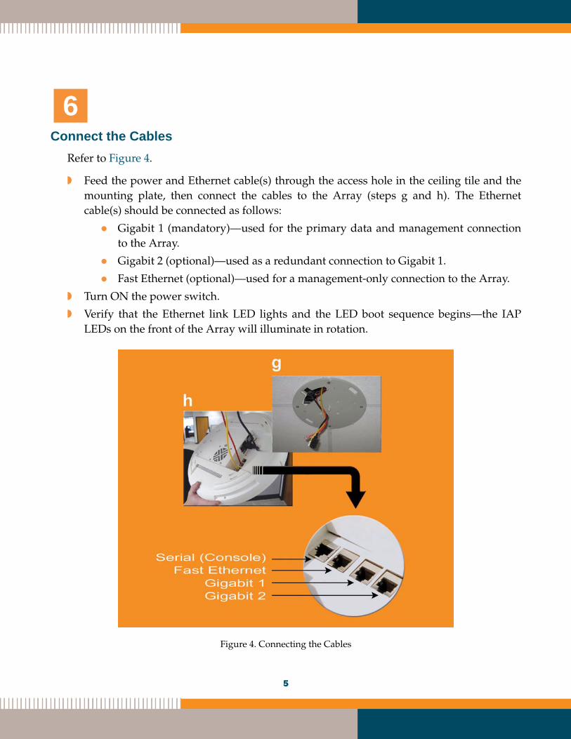
Connect the CablesRefer to Figure 4.
w Feed the power and Ethernet cable(s) through the access hole in the ceiling tile and the mounting plate, then connect the cables to the Array (steps g and h). The Ethernet cable(s) should be connected as follows:
Gigabit 1 (mandatory)—used for the primary data and management connection to the Array.
Gigabit 2 (optional)—used as a redundant connection to Gigabit 1.
Fast Ethernet (optional)—used for a management-only connection to the Array.
w Turn ON the power switch.
w Verify that the Ethernet link LED lights and the LED boot sequence begins—the IAP LEDs on the front of the Array will illuminate in rotation.
Figure 4. Connecting the Cables
6
5
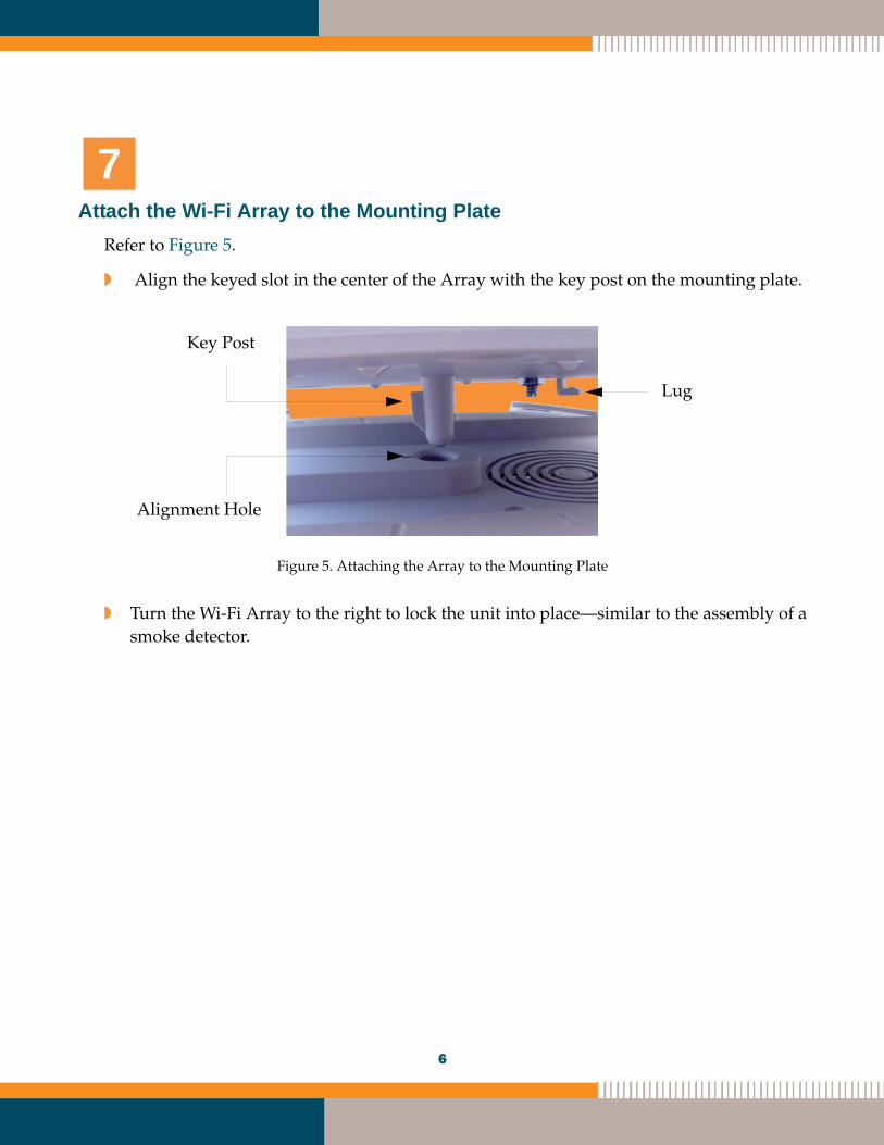
Attach the Wi-Fi Array to the Mounting PlateRefer to Figure 5.
w Align the keyed slot in the center of the Array with the key post on the mounting plate.
Figure 5. Attaching the Array to the Mounting Plate
w Turn the Wi-Fi Array to the right to lock the unit into place—similar to the assembly of a smoke detector.
7
Key Post
Alignment Hole
Lug
6
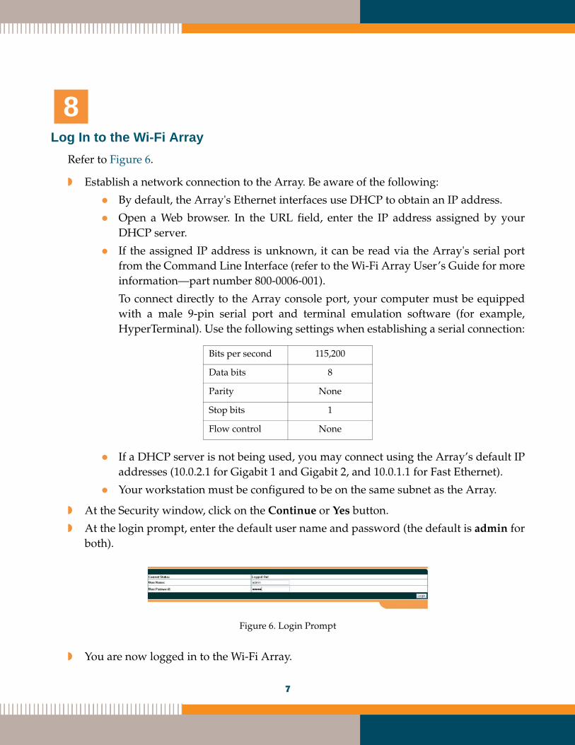
Log In to the Wi-Fi ArrayRefer to Figure 6.
w Establish a network connection to the Array. Be aware of the following:
By default, the Array's Ethernet interfaces use DHCP to obtain an IP address.
Open a Web browser. In the URL field, enter the IP address assigned by your DHCP server.
If the assigned IP address is unknown, it can be read via the Array's serial port from the Command Line Interface (refer to the Wi-Fi Array User’s Guide for more information—part number 800-0006-001).
To connect directly to the Array console port, your computer must be equipped with a male 9-pin serial port and terminal emulation software (for example, HyperTerminal). Use the following settings when establishing a serial connection:
If a DHCP server is not being used, you may connect using the Array’s default IP addresses (10.0.2.1 for Gigabit 1 and Gigabit 2, and 10.0.1.1 for Fast Ethernet).
Your workstation must be configured to be on the same subnet as the Array.
w At the Security window, click on the Continue or Yes button.
w At the login prompt, enter the default user name and password (the default is admin for both).
Figure 6. Login Prompt
w You are now logged in to the Wi-Fi Array.
Bits per second 115,200
Data bits 8
Parity None
Stop bits 1
Flow control None
8
7
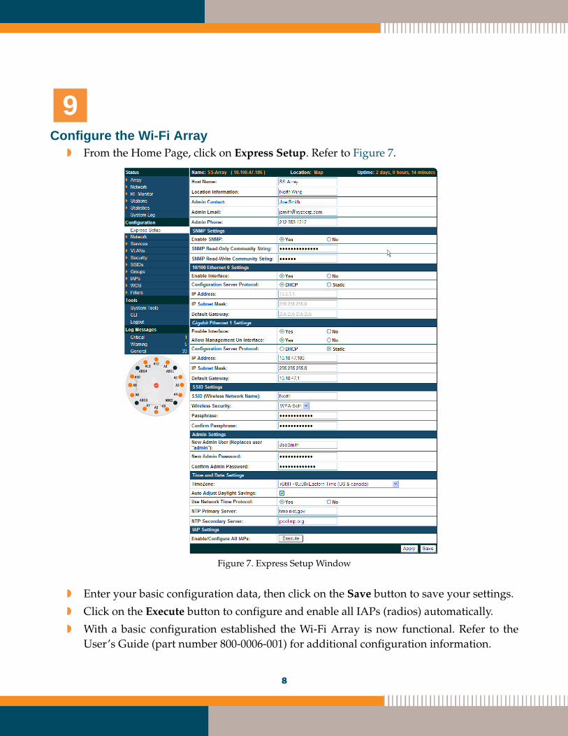
Configure the Wi-Fi Arrayw From the Home Page, click on Express Setup. Refer to Figure 7.
Figure 7. Express Setup Window
w Enter your basic configuration data, then click on the Save button to save your settings.
w Click on the Execute button to configure and enable all IAPs (radios) automatically.
w With a basic configuration established the Wi-Fi Array is now functional. Refer to the User’s Guide (part number 800-0006-001) for additional configuration information.
9
8
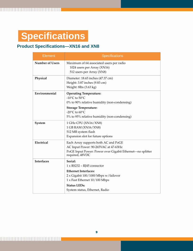
Product Specifications—XN16 and XN8
Element Specifications
Number of Users Maximum of 64 associated users per radio1024 users per Array (XN16)512 users per Array (XN8)
Physical Diameter: 18.65 inches (47.37 cm)Height: 3.87 inches (9.83 cm)Weight: 8lbs (3.63 kg)
Environmental Operating Temperature:-10°C to 50°C0% to 90% relative humidity (non-condensing)
Storage Temperature:-20°C to 60°C5% to 95% relative humidity (non-condensing)
System 1 GHz CPU (XN16/XN8)1 GB RAM (XN16/XN8)512 MB system flash Expansion slot for future options
Electrical Each Array supports both AC and PoGEAC Input Power: 90-265VAC at 47-63Hz PoGE Input Power: Power over Gigabit Ethernet—no splitter required, 48VDC
Interfaces Serial:1 x RS232 – RJ45 connector
Ethernet Interfaces:2 x Gigabit 100/1000 Mbps w/failover1 x Fast Ethernet 10/100 Mbps
Status LEDs:System status, Ethernet, Radio
Specifications
9
0
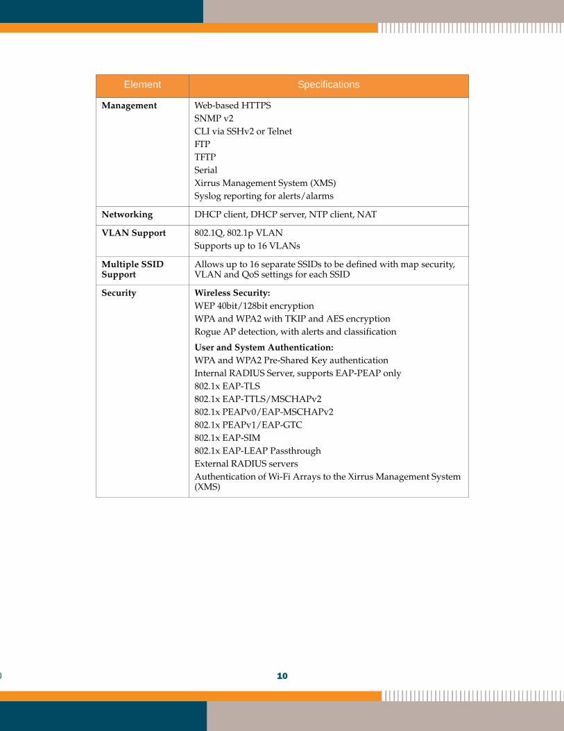
Management Web-based HTTPSSNMP v2CLI via SSHv2 or TelnetFTPTFTPSerialXirrus Management System (XMS)Syslog reporting for alerts/alarms
Networking DHCP client, DHCP server, NTP client, NAT
VLAN Support 802.1Q, 802.1p VLANSupports up to 16 VLANs
Multiple SSID Support
Allows up to 16 separate SSIDs to be defined with map security, VLAN and QoS settings for each SSID
Security Wireless Security:WEP 40bit/128bit encryptionWPA and WPA2 with TKIP and AES encryptionRogue AP detection, with alerts and classification
User and System Authentication:WPA and WPA2 Pre-Shared Key authenticationInternal RADIUS Server, supports EAP-PEAP only802.1x EAP-TLS802.1x EAP-TTLS/MSCHAPv2802.1x PEAPv0/EAP-MSCHAPv2802.1x PEAPv1/EAP-GTC802.1x EAP-SIM802.1x EAP-LEAP Passthrough External RADIUS serversAuthentication of Wi-Fi Arrays to the Xirrus Management System (XMS)
Element Specifications
10
1
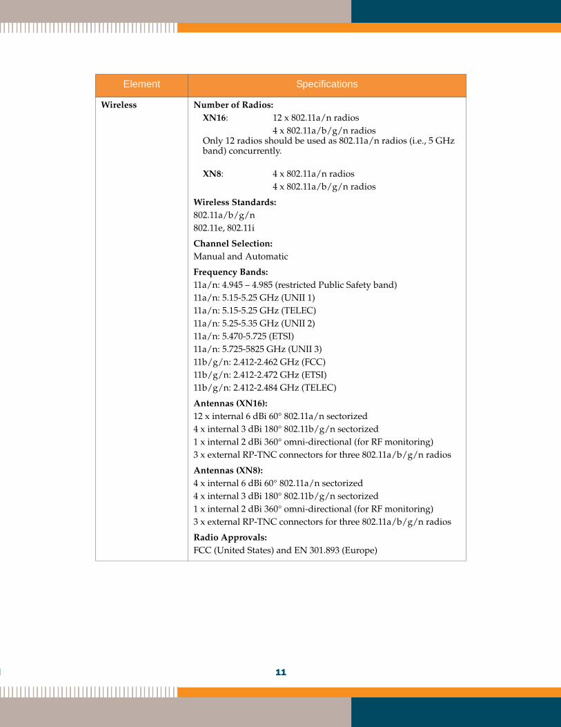
Wireless Number of Radios:XN16: 12 x 802.11a/n radios
4 x 802.11a/b/g/n radios Only 12 radios should be used as 802.11a/n radios (i.e., 5 GHz band) concurrently.
XN8: 4 x 802.11a/n radios4 x 802.11a/b/g/n radios
Wireless Standards:802.11a/b/g/n 802.11e, 802.11i
Channel Selection:Manual and Automatic
Frequency Bands: 11a/n: 4.945 – 4.985 (restricted Public Safety band)11a/n: 5.15-5.25 GHz (UNII 1)11a/n: 5.15-5.25 GHz (TELEC)11a/n: 5.25-5.35 GHz (UNII 2)11a/n: 5.470-5.725 (ETSI)11a/n: 5.725-5825 GHz (UNII 3)11b/g/n: 2.412-2.462 GHz (FCC)11b/g/n: 2.412-2.472 GHz (ETSI)11b/g/n: 2.412-2.484 GHz (TELEC)
Antennas (XN16):12 x internal 6 dBi 60° 802.11a/n sectorized4 x internal 3 dBi 180° 802.11b/g/n sectorized1 x internal 2 dBi 360° omni-directional (for RF monitoring)3 x external RP-TNC connectors for three 802.11a/b/g/n radios
Antennas (XN8):4 x internal 6 dBi 60° 802.11a/n sectorized4 x internal 3 dBi 180° 802.11b/g/n sectorized1 x internal 2 dBi 360° omni-directional (for RF monitoring)3 x external RP-TNC connectors for three 802.11a/b/g/n radios
Radio Approvals:FCC (United States) and EN 301.893 (Europe)
Element Specifications
11
2
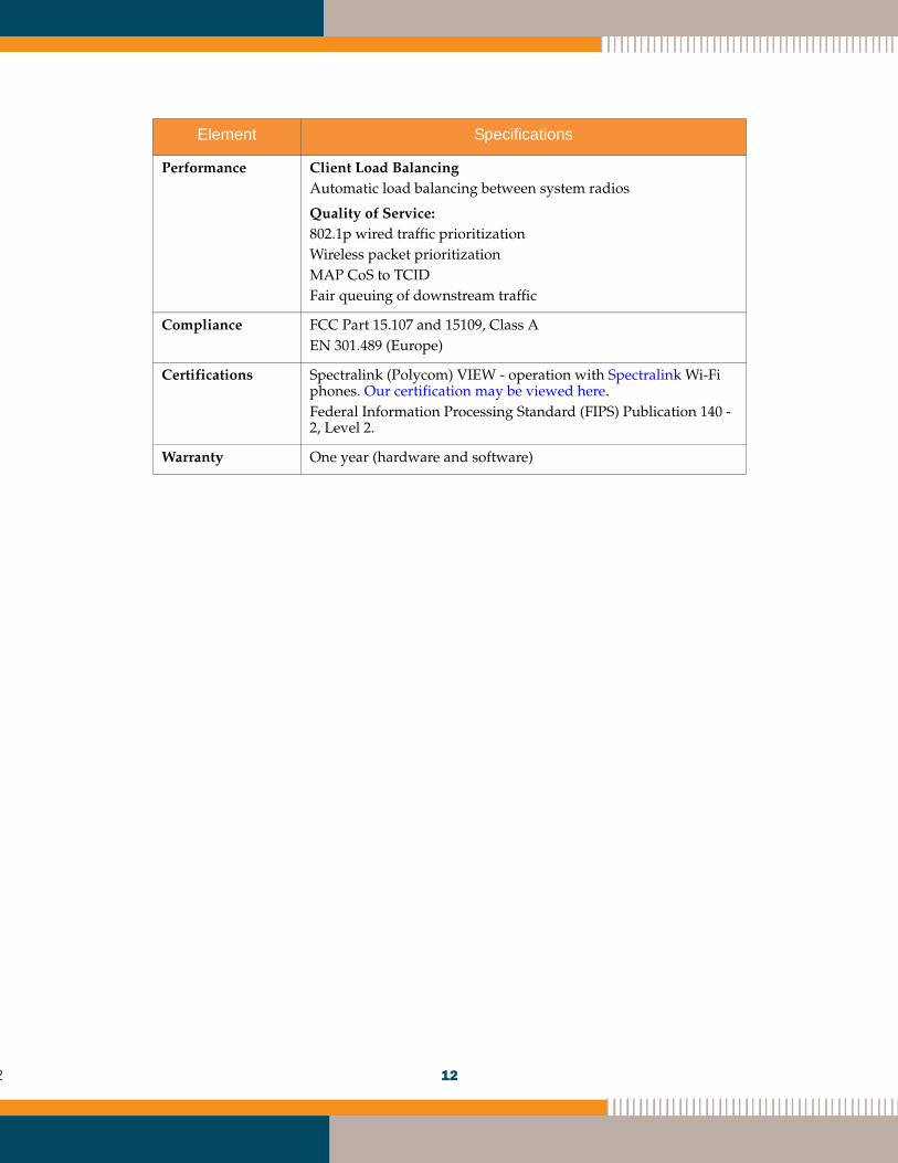
Performance Client Load BalancingAutomatic load balancing between system radios
Quality of Service:802.1p wired traffic prioritizationWireless packet prioritizationMAP CoS to TCIDFair queuing of downstream traffic
Compliance FCC Part 15.107 and 15109, Class AEN 301.489 (Europe)
Certifications Spectralink (Polycom) VIEW - operation with Spectralink Wi-Fi phones. Our certification may be viewed here. Federal Information Processing Standard (FIPS) Publication 140 -2, Level 2.
Warranty One year (hardware and software)
Element Specifications
12