Quick guide Danfoss aqua fc 200
40
Application Quick Guide VLT® AQUA Drive FC 200
-
Upload
cong-ty-co-phan-oks-ban-cua-co-dien-va-mua-hang -
Category
Automotive
-
view
170 -
download
0
Transcript of Quick guide Danfoss aqua fc 200
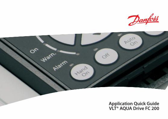
Application Quick Guide VLT® AQUA Drive FC 200
Safety instructions
This Application Quick Guide is intended only for use by trained specialists in conjunction with the product manuals for working on VLT® AQUA Drive FC 200 series frequency converters.
Hazardous voltages are present in the frequency converter when it is connected to the mains. Incorrect installation of the motor, frequency converter or control cables can cause irreparable damage to the frequency converter or system as well as serious or fatal injuries.
To prevent electrical shock, the frequency converter must be disconnected from the mains before performing all maintenance work. The DC link capacitors of the VLT® AQUA Drive FC 200 retain their charge for a very long time even after disconnecting the mains supply. It is therefore essential to wait for the duration of the period specified on the unit or in the product manual before carrying out any maintenance work after disconnecting the mains supply.
Always follow the instructions contained in the relevant product manuals as well as local and national rules and safety regulations.
The contents of this Application Quick Guide refer mainly to the basic unit of the VLT® AQUA Drive with graphical control panel (LCP 102) up to 90 kW (400 V) and initial operation with an asynchronous motor. For the sake of clarity, this Application Quick Guide does not cover all options and accessories or detailed differences with higher-power models or special variants. Please refer to the corresponding product manual in all cases.
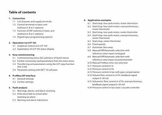
Table of contents
1. Connection 1.1 List of power and supply terminals 1.2 Control terminals in basic unit (without A, B or C options) 1.3 Function of DIP switches in basic unit (without A, B or C options) 1.4 Digital input programming options
2. Operation via LCP 102 2.1 Graphical control unit LCP 102 2.2 Explanation of LCP 102 status display
3. Easy commissioning 3.1 Commissioning menu (Q2 submenu of Quick menu) 3.2 Further commonly used parameters from the main menu 3.3 Transferring unit parameters using the LCP copy function (Par. 0.50) 3.4 Parameter setting with MCT 10 software
4. Profibus DP interface 4.1 General settings 4.2 Further settings
5. Fault analysis 5.1 Warnings, alarms, and alarm resetting 5.2 If the drive fails to restart after resetting an alarm 5.3 Warning and alarm indications
6. Application examples 6.1 Start/stop, four-pole motor, motor thermistor 6.2 Start/stop, four-pole motor, oversynchronous, motor thermistor 6.3 Start/stop, two-pole motor, motor thermistor 6.4 Start/stop, two-pole motor, oversynchronous, motor thermistor 6.5 Start/stop, motor thermistor 6.6 Fixed speeds 6.7 Automatic fast ramp 6.8 Manual/Off/Automatic selection with reference value input via keypad 6.9 Manual/Off/Automatic selection with reference value input via potentiometer 6.10 Manual Profibus time-out selection 6.11 Pressure control in % 6.12 Pressure control in Pa 6.13 Pressure control in bar with pipe compensation 6.14 Volume flow control in m³/h, feedback signal output 0–20 mA 6.15 Volumetric flow control in m³/h, oversynchronous, feedback signal output 0–20 mA 6.16 Pressure control in bar, basic cascade controller
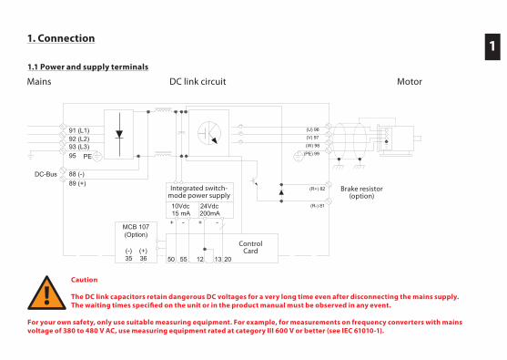
1. Connection
1.1 Power and supply terminals
Caution
The DC link capacitors retain dangerous DC voltages for a very long time even after disconnecting the mains supply. The waiting times specified on the unit or in the product manual must be observed in any event.
For your own safety, only use suitable measuring equipment. For example, for measurements on frequency converters with mains voltage of 380 to 480 V AC, use measuring equipment rated at category III 600 V or better (see IEC 61010-1).
1
91 (L1)92 (L2)93 (L3)
PE
88 (-)89 (+)
10Vdc15 mA 200mA
+ - + -
(U) 96
(V) 97
(W) 98
(PE) 99
Integr. Schaltnetzteil
DC-Bus
24Vdc
95
(R+) 82
(R-) 81
(Option)Bremswiderstand
20135550 12
Steuerkarte
MCB 107(Option)
(-)35
(+)36
DC-ZwischenkreisNetz MotorDC link circuitMains
Brake resistor(option)
Control Card
Integrated switch-mode power supply
Motor
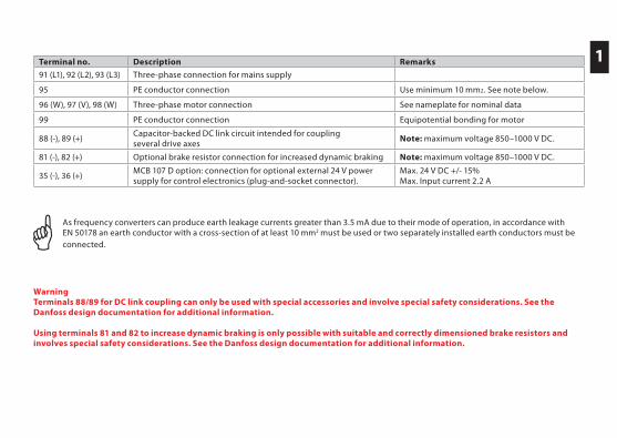
Terminal no. Description Remarks
91 (L1), 92 (L2), 93 (L3) Three-phase connection for mains supply
95 PE conductor connection Use minimum 10 mm2. See note below.
96 (W), 97 (V), 98 (W) Three-phase motor connection See nameplate for nominal data
99 PE conductor connection Equipotential bonding for motor
88 (-), 89 (+)Capacitor-backed DC link circuit intended for coupling several drive axes
Note: maximum voltage 850–1000 V DC.
81 (-), 82 (+) Optional brake resistor connection for increased dynamic braking Note: maximum voltage 850–1000 V DC.
35 (-), 36 (+)MCB 107 D option: connection for optional external 24 V power supply for control electronics (plug-and-socket connector).
Max. 24 V DC +/- 15%Max. Input current 2.2 A
As frequency converters can produce earth leakage currents greater than 3.5 mA due to their mode of operation, in accordance with EN 50178 an earth conductor with a cross-section of at least 10 mm2 must be used or two separately installed earth conductors must be connected.
WarningTerminals 88/89 for DC link coupling can only be used with special accessories and involve special safety considerations. See the Danfoss design documentation for additional information.
Using terminals 81 and 82 to increase dynamic braking is only possible with suitable and correctly dimensioned brake resistors and involves special safety considerations. See the Danfoss design documentation for additional information.
1
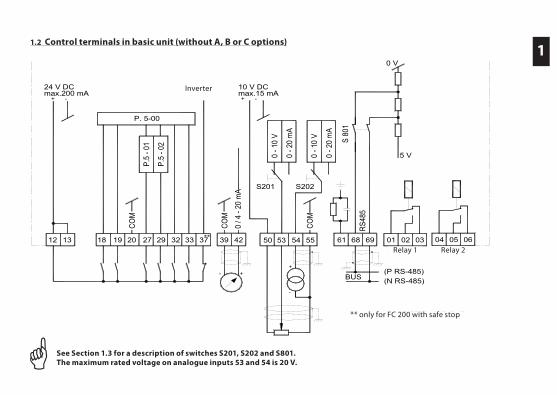
1.2 Control terminals in basic unit (without A, B or C options)1
12 13 18 19 20 27 29 32 33 39 42 50 53 54 55 61 68 69 01 02 03
- ++
-
COM
RS48
5
0 / 4
- 20
mA
COM
COM
24 V DCmax.200 mA
-+
0 V
5 V
BUS(P RS-485)(N RS-485)
37
S 80
1
P.5
- 02
P.5
- 01
P. 5-00
10 V DCmax.15 mA+ -
0 - 1
0 V
0 - 2
0 m
A
0 - 1
0 V
0 - 2
0 m
A
S202S201
0504 06
Wechsel-richter
**
Relais 1 Relais 2
** nur beim FC 200 mit Safe Stop
Inverter
Relay 1 Relay 2
** only for FC 200 with safe stop
See Section 1.3 for a description of switches S201, S202 and S801. The maximum rated voltage on analogue inputs 53 and 54 is 20 V.
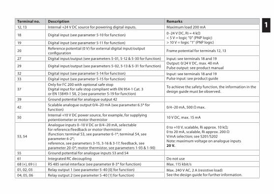
Terminal no. Description Remarks
12, 13 Internal +24 V DC source for powering digital inputs. Maximum load 200 mA
18 Digital input (see parameter 5-10 for function) 0–24 V DC, Ri = 4 kΩ < 5 V = logic “0” (PNP logic) > 10 V = logic “1” (PNP logic) 19 Digital input (see parameter 5-11 for function)
20Reference potential (0 V) for external digital input/output configuration
Frame potential for terminals 12, 13
27 Digital input/output (see parameters 5-01, 5-12 & 5-30 for function) Input: see terminals 18 and 19Output: 0/24 V DC, max. 40 mA Pulse output: see product manual29 Digital input/output (see parameters 5-02, 5-13 & 5-31 for function)
32 Digital input (see parameter 5-14 for function) Input: see terminals 18 and 19Pulse input: see product guide33 Digital input (see parameter 5-15 for function)
37Only for FC 200 with optional safe stopDigital input for safe stop compliant with EN 954-1 Cat. 3 or EN 13849-1 SIL 2 (see parameter 5-19 for function)
To achieve the safety function, the information in the design guide must be observed.
39 Ground potential for analogue output 42
42Scalable analogue output 0/4–20 mA (see parameter 6.5* for function)
0/4–20 mA, 500 Ω max.
50Internal +10 V DC power source, for example, for supplying potentiometer or motor thermistor
10 V DC, max. 15 mA
53, 54
Analogue inputs 0–10 V DC or 0/4–20 mA, selectable for reference/feedback or motor thermistor(function: terminal 53, see parameter 6-1*; terminal 54, see parameter 6-2*; reference, see parameters 3-15, 3-16 & 3-17; feedback, see parameter 20-0*; motor thermistor, see parameters 1-93 & 1-90)
0 to +10 V, scalable, Ri approx. 10 kΩ;0 to 20 mA, scalable, Ri approx. 200 ΩV/mA selection; see S201/S202Note: maximum voltage on analogue inputs 20 V.
55 Ground potential for analogue inputs 53 and 54
61 Integrated RC decoupling Do not use
68 (+), 69 (-) RS 485 serial interface (see parameter 8-3* for function) Max. 115 kbit/s
01, 02, 03 Relay output 1 (see parameter 5-40 [0] for function) Max. 240 V AC, 2 A (resistive load)See the design guide for further information.04, 05, 06 Relay output 2 (see parameter 5-40 [1] for function)
1
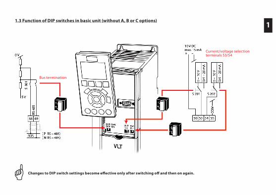
Changes to DIP switch settings become effective only after switching off and then on again.
1.3 Function of DIP switches in basic unit (without A, B or C options)1
Bus termination
Current/voltage selection terminals 53/54
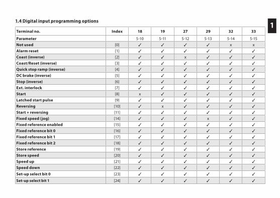
Terminal no. Index 18 19 27 29 32 33
Parameter 5-10 5-11 5-12 5-13 5-14 5-15
Not used [0] 3 3 3 3 x xAlarm reset [1] 3 3 3 3 3 3
Coast (inverse) [2] 3 3 x 3 3 3
Coast/Reset (inverse) [3] 3 3 3 3 3 3
Quick stop ramp (inverse) [4] 3 3 3 3 3 3
DC brake (inverse) [5] 3 3 3 3 3 3
Stop (inverse) [6] 3 3 3 3 3 3
Ext. interlock [7] 3 3 3 3 3 3
Start [8] x 3 3 3 3 3
Latched start pulse [9] 3 3 3 3 3 3
Reversing [10] 3 x 3 3 3 3
Start + reversing [11] 3 3 3 3 3 3
Fixed speed (jog) [14] 3 3 3 x 3 3
Fixed reference enabled [15] 3 3 3 3 3 3
Fixed reference bit 0 [16] 3 3 3 3 3 3
Fixed reference bit 1 [17] 3 3 3 3 3 3
Fixed reference bit 2 [18] 3 3 3 3 3 3
Store reference [19] 3 3 3 3 3 3
Store speed [20] 3 3 3 3 3 3
Speed up [21] 3 3 3 3 3 3
Speed down [22] 3 3 3 3 3 3
Set-up select bit 0 [23] 3 3 3 3 3 3
Set-up select bit 1 [24] 3 3 3 3 3 3
11.4 Digital input programming options
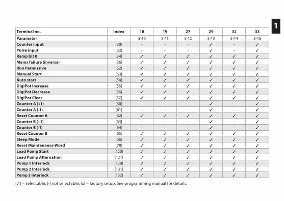
1 Terminal no. Index 18 19 27 29 32 33
Parameter 5-10 5-11 5-12 5-13 5-14 5-15
Counter input [30] - - - 3 - 3
Pulse input [32] - - - 3 - 3
Ramp bit 0 [34] 3 3 3 3 3 3
Mains failure (inverse) [36] 3 3 3 3 3 3
Run Permissive [52] 3 3 3 3 3 3
Manual Start [53] 3 3 3 3 3 3
Auto start [54] 3 3 3 3 3 3
DigiPot Increase [55] 3 3 3 3 3 3
DigiPot Decrease [56] 3 3 3 3 3 3
DigiPot Clear [57] 3 3 3 3 3 3
Counter A (+1) [60] - - - 3 - 3
Counter A (-1) [61] - - - 3 - 3
Reset Counter A [62] 3 3 3 3 3 3
Counter B (+1) [63] - - - 3 - 3
Counter B (-1) [64] - - - 3 - 3
Reset Counter B [65] 3 3 3 3 3 3
Sleep Mode [66] 3 3 3 3 3 3
Reset Maintenance Word [78] 3 3 3 3 3 3
Lead Pump Start [120] 3 3 3 3 3 3
Lead Pump Alternation [121] 3 3 3 3 3 3
Pump 1 Interlock [130] 3 3 3 3 3 3
Pump 2 Interlock [131] 3 3 3 3 3 3
Pump 3 Interlock [132] 3 3 3 3 3 3
[3] = selectable; [-] not selectable; [x] = factory setup. See programming manual for details.
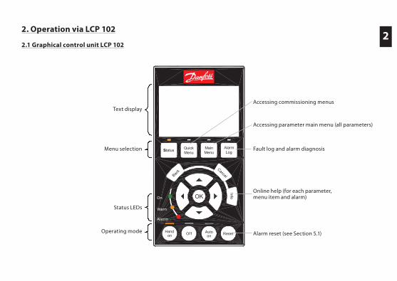
2. Operation via LCP 102
2.1 Graphical control unit LCP 102
Autoon ResetHand
on Of f
SStatus QuickMenu
MainMenu
AlarmLog
Back
Cancel
InfoOKOn
Alarm
Warn.
On
Warn
Alarm
Text display
Menu selection
Status LEDs
Operating mode
Accessing commissioning menus
Accessing parameter main menu (all parameters)
Fault log and alarm diagnosis
Online help (for each parameter, menu item and alarm)
Alarm reset (see Section 5.1)
2
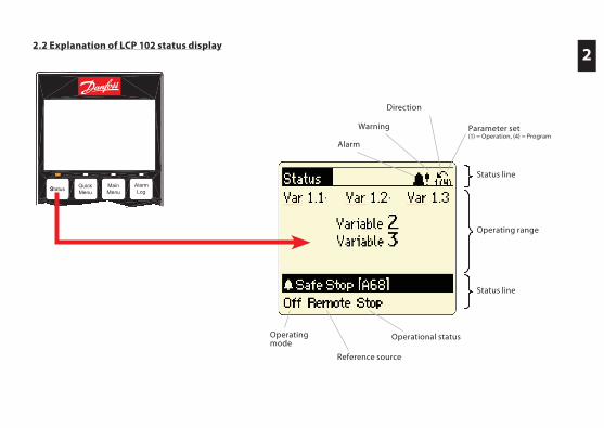
Alarm
Warning
Direction
Operational status
Reference source
Operating mode
Parameter set(1) = Operation, (4) = Program
Status line
Operating range
Status lineAutoon ResetHand
on Of f
SStatus QuickMenu
MainMenu
AlarmLog
Back
Cancel
InfoOKOn
Alarm
Warn.
On
Warn
Alarm
2.2 Explanation of LCP 102 status display2
3. Easy commissioning
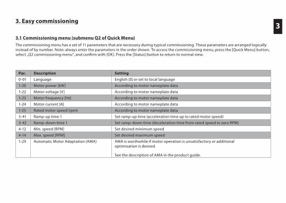
3.1 Commissioning menu (submenu Q2 of Quick Menu)The commissioning menu has a set of 11 parameters that are necessary during typical commissioning. These parameters are arranged logically instead of by number. Note: always enter the parameters in the order shown. To access the commissioning menu, press the [Quick Menu] button, select „Q2 commissioning menu“, and confirm with [OK]. Press the [Status] button to return to normal view.
Par. Description Setting
0-01 Language English [0] or set to local language
1-20 Motor power [kW] According to motor nameplate data
1-22 Motor voltage [V] According to motor nameplate data
1-23 Motor frequency [Hz] According to motor nameplate data
1-24 Motor current [A] According to motor nameplate data
1-25 Rated motor speed [rpm] According to motor nameplate data
3-41 Ramp-up time 1 Set ramp-up time (acceleration time up to rated motor speed)
3-42 Ramp-down time 1 Set ramp-down time (deceleration time from rated speed to zero RPM)
4-12 Min. speed [RPM] Set desired minimum speed
4-14 Max. speed [RPM] Set desired maximum speed
1-29 Automatic Motor Adaptation (AMA) AMA is worthwhile if motor operation is unsatisfactory or additional optimisation is desired. See the description of AMA in the product guide.
3
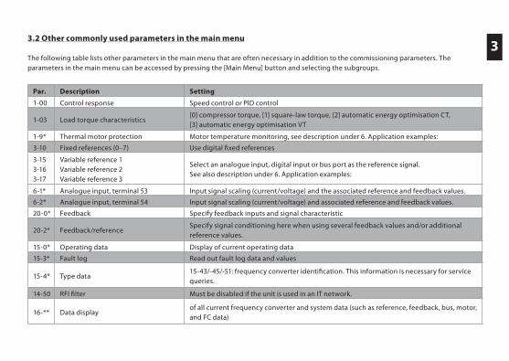
3.2 Other commonly used parameters in the main menu
The following table lists other parameters in the main menu that are often necessary in addition to the commissioning parameters. The parameters in the main menu can be accessed by pressing the [Main Menu] button and selecting the subgroups.
3
Par. Description Setting
1-00 Control response Speed control or PID control
1-03 Load torque characteristics[0] compressor torque, [1] square-law torque, [2] automatic energy optimisation CT, [3] automatic energy optimisation VT
1-9* Thermal motor protection Motor temperature monitoring, see description under 6. Application examples:
3-10 Fixed references (0–7) Use digital fixed references
3-15 3-16 3-17
Variable reference 1 Variable reference 2 Variable reference 3
Select an analogue input, digital input or bus port as the reference signal. See also description under 6. Application examples:
6-1* Analogue input, terminal 53 Input signal scaling (current/voltage) and the associated reference and feedback values.
6-2* Analogue input, terminal 54 Input signal scaling (current/voltage) and associated reference and feedback values.
20-0* Feedback Specify feedback inputs and signal characteristic
20-2* Feedback/referenceSpecify signal conditioning here when using several feedback values and/or additional reference values.
15-0* Operating data Display of current operating data
15-3* Fault log Read out fault log data and values
15-4* Type data15-43/-45/-51: frequency converter identification. This information is necessary for service queries.
14-50 RFI filter Must be disabled if the unit is used in an IT network.
16-** Data displayof all current frequency converter and system data (such as reference, feedback, bus, motor, and FC data)
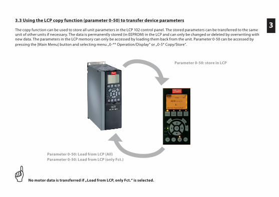
3.3 Using the LCP copy function (parameter 0-50) to transfer device parameters The copy function can be used to store all unit parameters in the LCP 102 control panel. The stored parameters can be transferred to the same unit of other units if necessary. The data is permanently stored (in EEPROM) in the LCP and can only be changed or deleted by overwriting with new data. The parameters in the LCP memory can only be accessed by loading them back from the unit. Parameter 0-50 can be accessed by pressing the [Main Menu] button and selecting menu „0-** Operation/Display“ or „0-5* Copy/Store“.
No motor data is transferred if „Load from LCP, only Fct.“ is selected.
Parameter 0-50: Load from LCP (All)Parameter 0-50: Load from LCP (only Fct.)
Parameter 0-50: store in LCP
3
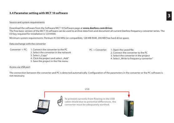
3.4 Parameter setting with MCT 10 software
Source and system requirements
Download the software from the Software/MCT 10 Software page at www.danfoss.com/drivesThe free basic version of the MCT 10 software can be used to archive data from and document all current Danfoss frequency converter series. The CD key required for installation is 12314500.
Minimum system requirements: Pentium III 350 MHz (or compatible), 128 MB RAM, 200 MB free hard drive space.
Data exchange with the converter
Converter -> PC: 1. Connect the converter to the PC 2. Select the converter in the network 3. Select „Copy“ 4. Click the project and select „Add“ 5. Save the project in the File menu
Access via USB port
The connection between the converter and PC is detected automatically. Confi guration of the parameters in the converter or the PC software is not necessary.
PC -> Converter: 1. Open the saved fi le 2. Connect the converter to the PC 3. Select the converter in the project 4. Select „Write to frequency converter“
3
USB
To prevent currents from fl owing in the USB cable shield due to potential diff erences, the converter must be adequately earthed.
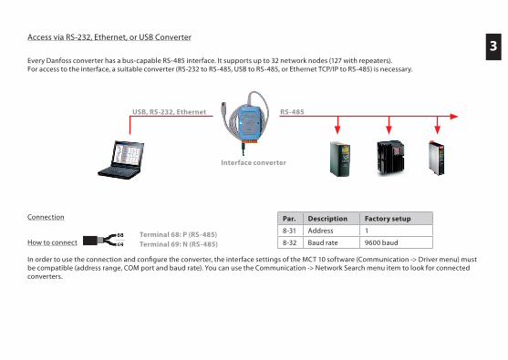
Access via RS-232, Ethernet, or USB Converter
Every Danfoss converter has a bus-capable RS-485 interface. It supports up to 32 network nodes (127 with repeaters). For access to the interface, a suitable converter (RS-232 to RS-485, USB to RS-485, or Ethernet TCP/IP to RS-485) is necessary.
Connection
How to connect
In order to use the connection and confi gure the converter, the interface settings of the MCT 10 software (Communication -> Driver menu) must be compatible (address range, COM port and baud rate). You can use the Communication -> Network Search menu item to look for connected converters.
Terminal 68: P (RS-485)Terminal 69: N (RS-485)
USB, RS-232, Ethernet RS-485
Interface converter
Par. Description Factory setup
8-31 Address 1
8-32 Baud rate 9600 baud
3
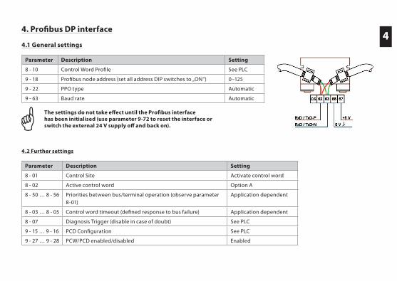
44. Profibus DP interface
4.1 General settings
The settings do not take effect until the Profibus interface has been initialised (use parameter 9-72 to reset the interface or switch the external 24 V supply off and back on).
4.2 Further settings
Parameter Description Setting
8 - 10 Control Word Profile See PLC
9 - 18 Profibus node address (set all address DIP switches to „ON“) 0–125
9 - 22 PPO type Automatic
9 - 63 Baud rate Automatic
Parameter Description Setting
8 - 01 Control Site Activate control word
8 - 02 Active control word Option A
8 - 50 … 8 - 56 Priorities between bus/terminal operation (observe parameter 8-01)
Application dependent
8 - 03 … 8 - 05 Control word timeout (defined response to bus failure) Application dependent
8 - 07 Diagnosis Trigger (disable in case of doubt) See PLC
9 - 15 … 9 - 16 PCD Configuration See PLC
9 - 27 … 9 - 28 PCW/PCD enabled/disabled Enabled
5. Fault analysis
5.1 Warnings, alarms, and alarm resetting5
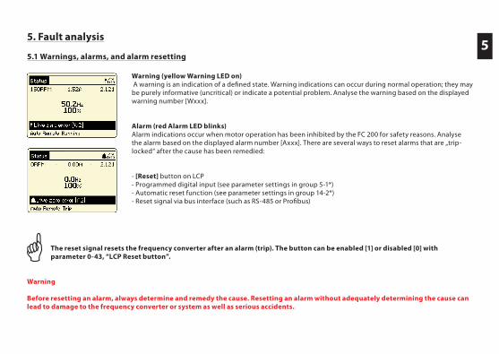
Warning (yellow Warning LED on) A warning is an indication of a defined state. Warning indications can occur during normal operation; they may be purely informative (uncritical) or indicate a potential problem. Analyse the warning based on the displayed warning number [Wxxx].
Alarm (red Alarm LED blinks)Alarm indications occur when motor operation has been inhibited by the FC 200 for safety reasons. Analyse the alarm based on the displayed alarm number [Axxx]. There are several ways to reset alarms that are „trip-locked“ after the cause has been remedied:
- [Reset] button on LCP- Programmed digital input (see parameter settings in group 5-1*)- Automatic reset function (see parameter settings in group 14-2*)- Reset signal via bus interface (such as RS-485 or Profibus)
The reset signal resets the frequency converter after an alarm (trip). The button can be enabled [1] or disabled [0] with parameter 0-43, “LCP Reset button”.
Warning
Before resetting an alarm, always determine and remedy the cause. Resetting an alarm without adequately determining the cause can lead to damage to the frequency converter or system as well as serious accidents.
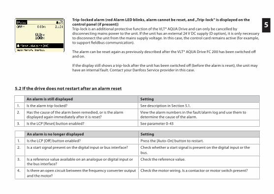
5Trip-locked alarm (red Alarm LED blinks, alarm cannot be reset, and „Trip-lock“ is displayed on the control panel (if present))Trip-lock is an additional protective function of the VLT® AQUA Drive and can only be cancelled by disconnecting mains power to the unit. If the unit has an external 24 V DC supply (D option), it is only necessary to disconnect the unit from the mains supply voltage. In this case, the control card remains active (for example, to support fieldbus communication).
The alarm can be reset again as previously described after the VLT® AQUA Drive FC 200 has been switched off and on.
If the display still shows a trip-lock after the unit has been switched off (before the alarm is reset), the unit may have an internal fault. Contact your Danfoss Service provider in this case.
5.2 If the drive does not restart after an alarm reset
An alarm is still displayed Setting
1. Is the alarm trip-locked? See description in Section 5.1.
2. Has the cause of the alarm been remedied, or is the alarm displayed again immediately after it is reset?
View the alarm numbers in the fault/alarm log and use them to determine the cause of the alarm.
3. Is the LCP [Reset] button enabled? See parameter 0-43
An alarm is no longer displayed Setting
1. Is the LCP [Off] button enabled? Press the [Auto-On] button to restart.
2. Is a start signal present on the digital input or bus interface? Check whether a start signal is present on the digital input or the bus.
3. Is a reference value available on an analogue or digital input orthe bus interface?
Check the reference value.
4. Is there an open circuit between the frequency converter output and the motor?
Check the motor wiring. Is a contactor or motor switch present?
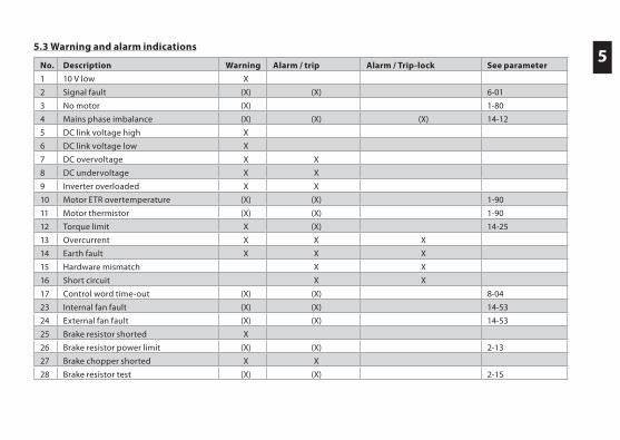
55.3 Warning and alarm indications
No. Description Warning Alarm / trip Alarm / Trip-lock See parameter
1 10 V low X
2 Signal fault (X) (X) 6-01
3 No motor (X) 1-80
4 Mains phase imbalance (X) (X) (X) 14-12
5 DC link voltage high X
6 DC link voltage low X
7 DC overvoltage X X
8 DC undervoltage X X
9 Inverter overloaded X X
10 Motor ETR overtemperature (X) (X) 1-90
11 Motor thermistor (X) (X) 1-90
12 Torque limit X (X) 14-25
13 Overcurrent X X X
14 Earth fault X X X
15 Hardware mismatch X X
16 Short circuit X X
17 Control word time-out (X) (X) 8-04
23 Internal fan fault (X) (X) 14-53
24 External fan fault (X) (X) 14-53
25 Brake resistor shorted X
26 Brake resistor power limit (X) (X) 2-13
27 Brake chopper shorted X X
28 Brake resistor test (X) (X) 2-15
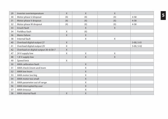
529 Inverter overtemperature X X X
30 Motor phase U dropout (X) (X) (X) 4-58
31 Motor phase V dropout (X) (X) (X) 4-58
32 Motor phase W dropout (X) (X) (X) 4-58
33 Inrush fault X X
34 Fieldbus fault X (X)
36 Mains failure X X
38 Internal fault X X
40 Overload digital output 27 X 5-00, 5-01
41 Overload digital output 29 X 5-00, 5-02
42 Overload on digital output 30-6/30-7 X
47 24 V supply low X X X
48 1.8 V supply low X X
49 Speed limit X
50 AMA calibration fault X
51 AMA check Unom and Inom X
52 AMA low Inom X
53 AMA motor too big X
54 AMA motor too small X
55 AMA parameter out of range X
56 AMA interrupted by user X
57 AMA timeout X
58 AMA internal fault X X
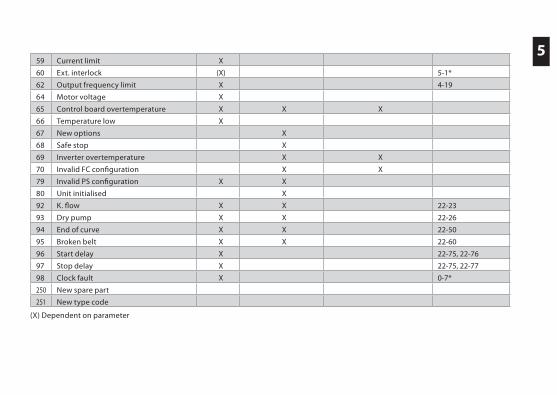
5 59 Current limit X
60 Ext. interlock (X) 5-1*
62 Output frequency limit X 4-19
64 Motor voltage X
65 Control board overtemperature X X X
66 Temperature low X
67 New options X
68 Safe stop X
69 Inverter overtemperature X X
70 Invalid FC configuration X X
79 Invalid PS configuration X X
80 Unit initialised X
92 K. flow X X 22-23
93 Dry pump X X 22-26
94 End of curve X X 22-50
95 Broken belt X X 22-60
96 Start delay X 22-75, 22-76
97 Stop delay X 22-75, 22-77
98 Clock fault X 0-7*
250 New spare part
251 New type code
(X) Dependent on parameter
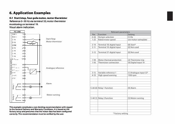
6. Application Examples6
This example constitutes a non-binding recommendation with regard to the General Delivery and Warranty Conditions. It is based on the factory setup and presumes that the motor data has been confi gured correctly. This recommendation must be verifi ed by the user.
6.1 Start/stop, four-pole motor, motor thermistorReference 0–50 Hz via terminal 53; motor thermistor monitoring on terminal 19.Visual alarm indication.
6. Application Examples6. Application Examples6
This example constitutes a non-binding recommendation with regard to the General Delivery and Warranty Conditions. It is based on the factory setup and presumes that the motor data has been confi gured correctly. This recommendation must be verifi ed by the user.
6.1 Start/stop, four-pole motor, motor thermistorReference 0–50 Hz via terminal 53; motor thermistor monitoring on terminal 19.Visual alarm indication.
Relevant parametersPar. Function Setting0-02 Hz/rpm selection [1] Hz1-25 Rated motor speed see motor nameplate
5-10 Terminal 18: digital input [8] Start*5-11 Terminal 19: digital input [0] Not used
5-12 Terminal 27: digital input [0] Not used
1-90 Motor thermal protection [2] Thermistor trip1-93 Thermistor connection [4] Digital input 19
3-15 Variable reference 1 [1] Analogue input 53*4-53 High speed warning 1500 rpm
5-40 [0] Relay 1 function [9] Alarm
5-40 [1] Relay 2 function [5] Motor running
* Factory setting
Start/StopMotor thermistor
Analogue reference
Alarm
Motor running
*Saf
e st
op
as
op
tio
nRe
lay
2Re
lay
1
6
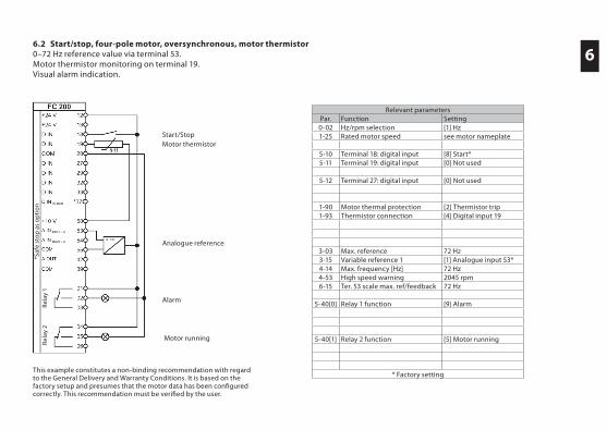
This example constitutes a non-binding recommendation with regard to the General Delivery and Warranty Conditions. It is based on the factory setup and presumes that the motor data has been confi gured correctly. This recommendation must be verifi ed by the user.
6.2 Start/stop, four-pole motor, oversynchronous, motor thermistor0–72 Hz reference value via terminal 53.Motor thermistor monitoring on terminal 19.Visual alarm indication.
Relevant parametersPar. Function Setting0-02 Hz/rpm selection [1] Hz1-25 Rated motor speed see motor nameplate
5-10 Terminal 18: digital input [8] Start*5-11 Terminal 19: digital input [0] Not used
5-12 Terminal 27: digital input [0] Not used
1-90 Motor thermal protection [2] Thermistor trip1-93 Thermistor connection [4] Digital input 19
3-03 Max. reference 72 Hz3-15 Variable reference 1 [1] Analogue input 53*4-14 Max. frequency [Hz] 72 Hz4-53 High speed warning 2045 rpm6-15 Ter. 53 scale max. ref/feedback 72 Hz
5-40[0] Relay 1 function [9] Alarm
5-40[1] Relay 2 function [5] Motor running
* Factory setting
Start/StopMotor thermistor
Analogue reference
Alarm
Motor running
*Saf
e st
op
as
op
tio
nRe
lay
2Re
lay
1
6
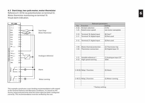
This example constitutes a non-binding recommendation with regard to the General Delivery and Warranty Conditions. It is based on the factory setup and presumes that the motor data has been confi gured correctly. This recommendation must be verifi ed by the user.
6.3 Start/stop, two-pole motor, motor thermistorReference 0–50 Hz via potentiometer on terminal 53.Motor thermistor monitoring on terminal 19.Visual alarm indication.
Relevant parametersPar. Function Setting0-02 Hz/rpm selection [1] Hz1-25 Rated motor speed see motor nameplate
5-10 Terminal 18: digital input [8] Start*5-11 Terminal 19: digital input [0] Not used
5-12 Terminal 27: digital input [0] Not used
1-90 Motor thermal protection [2] Thermistor trip1-93 Thermistor connection [4] Digital input 19
3-15 Variable reference 1 [1] Analogue input 53*4-53 High speed warning 3000
5-40 [0] Relay 1 function [9] Alarm
5-40 [1] Relay 2 function [5] Motor running
* Factory setting
Start/StopMotor thermistor
Analogue reference
Alarm
Motor running
*Saf
e st
op
as
op
tio
nRe
lay
2Re
lay
1
6
This example constitutes a non-binding recommendation with regard to the General Delivery and Warranty Conditions. It is based on the factory setup and presumes that the motor data has been confi gured correctly. This recommendation must be verifi ed by the user.
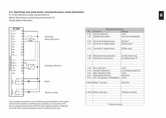
6.4 Start/stop, two-pole motor, oversynchronous, motor thermistor0–72 Hz reference value via terminal 53.Motor thermistor monitoring on terminal 19.Visual alarm indication.
Start/StopMotor thermistor
Analogue reference
Alarm
Motor running
Relevant parametersPar. Function Setting0-02 Hz/rpm selection [1] Hz1-25 Rated motor speed see motor nameplate
5-10 Terminal 18: digital input [8] Start*5-11 Terminal 19: digital input [0] Not used
5-12 Terminal 27: digital input [0] Not used
1-90 Motor thermal protection [2] Thermistor trip1-93 Thermistor connection [4] Digital input 19
3-03 Max. reference 72 Hz3-15 Variable reference 1 [1] Analogue input 53*4-14 Max. frequency [Hz] 72 Hz4-53 High speed warning 4320 rpm6-15 Ter. 53 scale max. ref/feedback 72 Hz
5-40 [0] Relay 1 function [9] Alarm
5-40 [1] Relay 2 function [5] Motor running
* Factory setting
*Saf
e st
op
as
op
tio
nRe
lay
2Re
lay
1
6
This example constitutes a non-binding recommendation with regard to the General Delivery and Warranty Conditions. It is based on the factory setup and presumes that the motor data has been confi gured correctly. This recommendation must be verifi ed by the user.
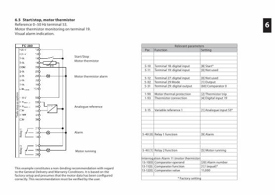
6.5 Start/stop, motor thermistorReference 0–50 Hz terminal 53.Motor thermistor monitoring on terminal 19.Visual alarm indication.
Start/StopMotor thermistor
Analogue reference
Alarm
Motor running
Motor thermistor alarm
Relevant parametersPar. Function Setting
5-10 Terminal 18: digital input [8] Start*5-11 Terminal 19: digital input [0] Not used
5-12 Terminal 27: digital input [0] Not used5-02 Terminal 29 Mode [1] Output5-31 Terminal 29: digital output [60] Comparator 0
1-90 Motor thermal protection [2] Thermistor trip1-93 Thermistor connection [4] Digital input 19
3-15 Variable reference 1 [1] Analogue input 53*
5-40 [0] Relay 1 function [9] Alarm
5-40 [1] Relay 2 function [5] Motor running
Interrogation Alarm 11 (motor thermistor)13-10[0] Comparator operand [20] Alarm number13-11[0] Comparator function [1] ! (equal)*13-12[0] Comparator value 11,000
* Factory setting
*Saf
e st
op
as
op
tio
nRe
lay
2Re
lay
1
6
This example constitutes a non-binding recommendation with regard to the General Delivery and Warranty Conditions. It is based on the factory setup and presumes that the motor data has been confi gured correctly. This recommendation must be verifi ed by the user.
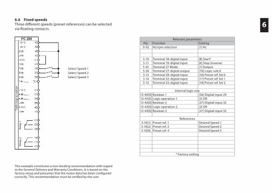
6.6 Fixed speedsThree diff erent speeds (preset references) can be selected via fl oating contacts.
Select Speed 1Select Speed 2Select Speed 3
Relevant parametersPar. Function Setting0-02 Hz/rpm selection [1] Hz
5-10 Terminal 18: digital input [8] Start*5-11 Terminal 19: digital input [6] Stop (inverse)5-01 Terminal 27 Mode [1] Output5-30 Terminal 27: digital output [70] Logic rule 05-13 Terminal 29: digital input [16] Preset ref. bit 05-14 Terminal 32: digital input [17] Preset ref. bit 15-15 Terminal 33: digital input [18] Preset ref. bit 2
Internal logic rule13-40[0] Boolean 1 [36] Digital input 2913-41[0] Logic operation 1 [2] OR13-42[0] Boolean 2 [37] Digital input 3213-43[0] Logic operation 2 [2] OR13-44[0] Boolean 3 [37] Digital input 33
References3-10[1] Preset ref. 1 Desired Speed 13-10[2] Preset ref. 2 Desired Speed 23-10[4] Preset ref. 4 Desired Speed 3
* Factory setting
*Saf
e st
op
as
op
tio
nRe
lay
2Re
lay
1
6
This example constitutes a non-binding recommendation with regard to the General Delivery and Warranty Conditions. It is based on the factory setup and presumes that the motor data has been confi gured correctly. This recommendation must be verifi ed by the user.
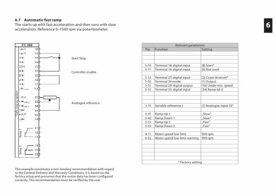
6.7 Automatic fast rampThe starts up with fast acceleration and then runs with slow acceleration. Reference 0–1500 rpm via potentiometer.
Relevant parametersPar. Function Setting
5-10 Terminal 18: digital input [8] Start*5-11 Terminal 19: digital input [0] Not used
5-12 Terminal 27: digital input [2] Coast (inverse)*5-02 Terminal 29 mode [1] Output5-31 Terminal 29: digital output [16] Under min. speed5-15 Terminal 33: digital input [34] Ramp bit 0
3-15 Variable reference 1 [1] Analogue input 53*
3-41 Ramp Up 1 „Slow“3-42 Ramp Down 1 „Slow“3-51 Ramp Up 2 „Fast“3-52 Ramp Down 2 „Fast“
4-11 Motor speed low limit 900 rpm4-52 Motor speed low limit warning 900 rpm
* Factory setting
Start/Stop
Analogue reference
Controller enable
*Saf
e st
op
as
op
tio
nRe
lay
2Re
lay
1
6
This example constitutes a non-binding recommendation with regard to the General Delivery and Warranty Conditions. It is based on the factory setup and presumes that the motor data has been confi gured correctly. This recommendation must be verifi ed by the user.
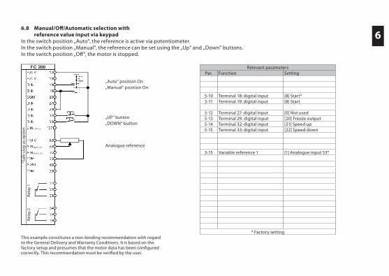
6.8 Manual/Off /Automatic selection with reference value input via keypadIn the switch position „Auto“, the reference is active via potentiometer.In the switch position „Manual“, the reference can be set using the „Up“ and „Down“ buttons.In the switch position „Off “, the motor is stopped.
Relevant parametersPar. Function Setting
5-10 Terminal 18: digital input [8] Start*5-11 Terminal 19: digital input [8] Start
5-12 Terminal 27: digital input [0] Not used5-13 Terminal 29: digital input [20] Freeze output5-14 Terminal 32: digital input [21] Speed up5-15 Terminal 33: digital input [22] Speed down
3-15 Variable reference 1 [1] Analogue input 53*
* Factory setting
„Auto“ position On„Manual“ position On
„UP“ button„DOWN“ button
Analogue reference
*Saf
e st
op
as
op
tio
nRe
lay
2Re
lay
1
6
This example constitutes a non-binding recommendation with regard to the General Delivery and Warranty Conditions. It is based on the factory setup and presumes that the motor data has been confi gured correctly. This recommendation must be verifi ed by the user.
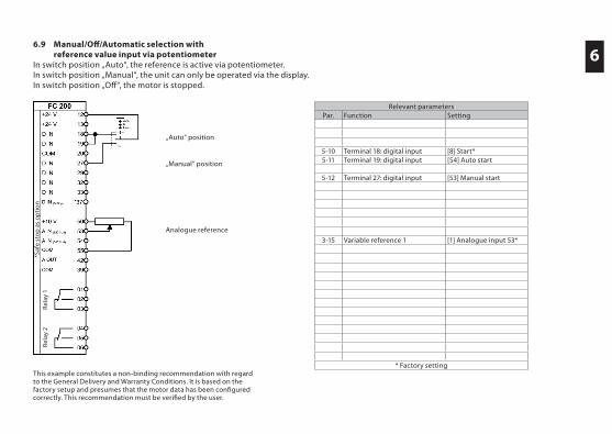
6.9 Manual/Off /Automatic selection with reference value input via potentiometerIn switch position „Auto“, the reference is active via potentiometer.In switch position „Manual“, the unit can only be operated via the display.In switch position „Off “, the motor is stopped.
Relevant parametersPar. Function Setting
5-10 Terminal 18: digital input [8] Start*5-11 Terminal 19: digital input [54] Auto start
5-12 Terminal 27: digital input [53] Manual start
3-15 Variable reference 1 [1] Analogue input 53*
* Factory setting
„Auto“ position
„Manual“ position
Analogue reference
*Saf
e st
op
as
op
tio
nRe
lay
2Re
lay
1
6
This example constitutes a non-binding recommendation with regard to the General Delivery and Warranty Conditions. It is based on the factory setup and presumes that the motor data has been confi gured correctly. This recommendation must be verifi ed by the user.
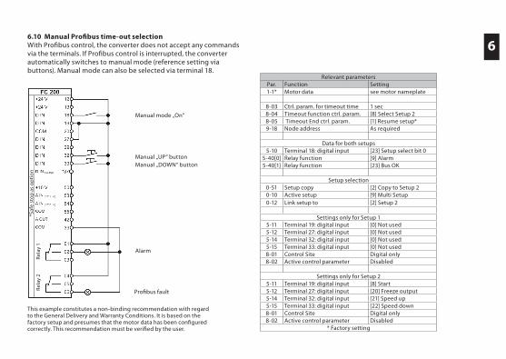
6.10 Manual Profi bus time-out selectionWith Profi bus control, the converter does not accept any commands via the terminals. If Profi bus control is interrupted, the converter automatically switches to manual mode (reference setting via buttons). Manual mode can also be selected via terminal 18.
Relevant parametersPar. Function Setting1-1* Motor data see motor nameplate
8-03 Ctrl. param. for timeout time 1 sec8-04 Timeout function ctrl. param. [8] Select Setup 28-05 Timeout End ctrl. param. [1] Resume setup*9-18 Node address As required
Data for both setups5-10 Terminal 18: digital input [23] Setup select bit 0
5-40[0] Relay function [9] Alarm5-40[1] Relay function [23] Bus OK
Setup selection0-51 Setup copy [2] Copy to Setup 20-10 Active setup [9] Multi Setup0-12 Link setup to [2] Setup 2
Settings only for Setup 15-11 Terminal 19: digital input [0] Not used5-12 Terminal 27: digital input [0] Not used5-14 Terminal 32: digital input [0] Not used5-15 Terminal 33: digital input [0] Not used8-01 Control Site Digital only8-02 Active control parameter Disabled
Settings only for Setup 25-11 Terminal 19: digital input [8] Start5-12 Terminal 27: digital input [20] Freeze output5-14 Terminal 32: digital input [21] Speed up5-15 Terminal 33: digital input [22] Speed down8-01 Control Site Digital only8-02 Active control parameter Disabled
* Factory setting
Manual mode „On“
Manual „UP“ buttonManual „DOWN“ button
Alarm
Profi bus fault
*Saf
e st
op
as
op
tio
nRe
lay
2Re
lay
1
6
This example constitutes a non-binding recommendation with regard to the General Delivery and Warranty Conditions. It is based on the factory setup and presumes that the motor data has been confi gured correctly. This recommendation must be verifi ed by the user.
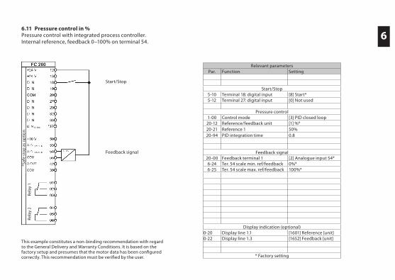
6.11 Pressure control in %Pressure control with integrated process controller.Internal reference, feedback 0–100% on terminal 54.
Relevant parametersPar. Function Setting
Start/Stop5-10 Terminal 18: digital input [8] Start*5-12 Terminal 27: digital input [0] Not used
Pressure control1-00 Control mode [3] PID closed loop20-12 Reference/feedback unit [1] %*20-21 Reference 1 50%20-94 PID integration time 0.8
Feedback signal20-00 Feedback terminal 1 [2] Analogue input 54*6-24 Ter. 54 scale min. ref/feedback 0%*6-25 Ter. 54 scale max. ref/feedback 100%*
Display indication (optional)0-20 Display line 1.1 [1601] Reference [unit]0-22 Display line 1.3 [1652] Feedback [unit]
* Factory setting
Feedback signal
Start/Stop
*Saf
e st
op
as
op
tio
nRe
lay
2Re
lay
1
6
This example constitutes a non-binding recommendation with regard to the General Delivery and Warranty Conditions. It is based on the factory setup and presumes that the motor data has been confi gured correctly. This recommendation must be verifi ed by the user.
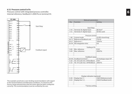
6.12 Pressure control in PaPressure control with integrated process controller.Internal reference, feedback 0–2000 Pa on terminal 54.
Relevant parametersPar. Function Setting
Start/Stop5-10 Terminal 18: digital input [8] Start*5-12 Terminal 27: digital input [0] Not used
Pressure control1-00 Control mode [3] PID closed loop20-12 Reference/feedback unit [72] Pa20-21 Reference 1 1500 Pa20-94 PID integration time 0.8
Scaling in Pa3-02 Min. reference 0 Pa*3-03 Max. reference 2000 Pa
Feedback signal20-00 Feedback terminal 1 [2] Analogue input 54*6-24 Ter. 54 scale min. ref/feedback 0 Pa*6-25 Ter. 54 scale max. ref/feedback 2000 Pa
Display indication (optional)0-20 Display line 1.1 [1601] Reference [unit]0-22 Display line 1.3 [1652] Feedback [unit]
* Factory setting
Feedback signal
Start/Stop
*Saf
e st
op
as
op
tio
nRe
lay
2Re
lay
1
6
This example constitutes a non-binding recommendation with regard to the General Delivery and Warranty Conditions. It is based on the factory setup and presumes that the motor data has been confi gured correctly. This recommendation must be verifi ed by the user.
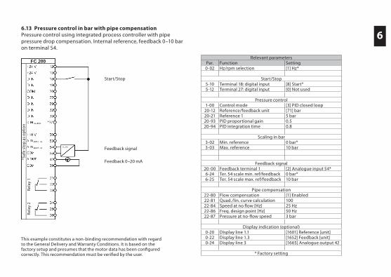
6.13 Pressure control in bar with pipe compensationPressure control using integrated process controller with pipe pressure drop compensation. Internal reference, feedback 0–10 bar on terminal 54.
Relevant parametersPar. Function Setting0-02 Hz/rpm selection [1] Hz*
Start/Stop5-10 Terminal 18: digital input [8] Start*5-12 Terminal 27: digital input [0] Not used
Pressure control1-00 Control mode [3] PID closed loop20-12 Reference/feedback unit [71] bar20-21 Reference 1 5 bar20-93 PID proportional gain 0.520-94 PID integration time 0.8
Scaling in bar3-02 Min. reference 0 bar*3-03 Max. reference 10 bar
Feedback signal20-00 Feedback terminal 1 [2] Analogue input 54*6-24 Ter. 54 scale min. ref/feedback 0 bar*6-25 Ter. 54 scale max. ref/feedback 10 bar
Pipe compensation22-80 Flow compensation [1] Enabled22-81 Quad./lin. curve calculation 10022-84 Speed at no fl ow [Hz] 25 Hz22-86 Freq. design point [Hz] 50 Hz22-87 Pressure at no-fl ow speed 3 bar
Display indication (optional)0-20 Display line 1.1 [1601] Reference [unit]0-22 Display line 1.3 [1652] Feedback [unit]0-24 Display line 3 [1665] Analogue output 42
* Factory setting
Feedback signal
Feedback 0–20 mA
Start/Stop
*Saf
e st
op
as
op
tio
nRe
lay
2Re
lay
1
6
This example constitutes a non-binding recommendation with regard to the General Delivery and Warranty Conditions. It is based on the factory setup and presumes that the motor data has been confi gured correctly. This recommendation must be verifi ed by the user.
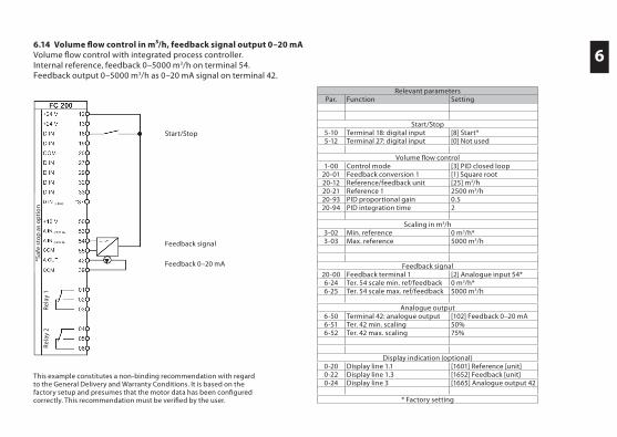
6.14 Volume fl ow control in m³/h, feedback signal output 0–20 mAVolume fl ow control with integrated process controller.Internal reference, feedback 0–5000 m3/h on terminal 54.Feedback output 0–5000 m3/h as 0–20 mA signal on terminal 42.
Relevant parametersPar. Function Setting
Start/Stop5-10 Terminal 18: digital input [8] Start*5-12 Terminal 27: digital input [0] Not used
Volume fl ow control1-00 Control mode [3] PID closed loop
20-01 Feedback conversion 1 [1] Square root20-12 Reference/feedback unit [25] m3/h20-21 Reference 1 2500 m3/h20-93 PID proportional gain 0.520-94 PID integration time 2
Scaling in m3/h3-02 Min. reference 0 m3/h*3-03 Max. reference 5000 m3/h
Feedback signal20-00 Feedback terminal 1 [2] Analogue input 54*6-24 Ter. 54 scale min. ref/feedback 0 m3/h*6-25 Ter. 54 scale max. ref/feedback 5000 m3/h
Analogue output6-50 Terminal 42: analogue output [102] Feedback 0–20 mA6-51 Ter. 42 min. scaling 50%6-52 Ter. 42 max. scaling 75%
Display indication (optional)0-20 Display line 1.1 [1601] Reference [unit]0-22 Display line 1.3 [1652] Feedback [unit]0-24 Display line 3 [1665] Analogue output 42
* Factory setting
Feedback signal
Feedback 0–20 mA
Start/Stop
*Saf
e st
op
as
op
tio
nRe
lay
2Re
lay
1
6
This example constitutes a non-binding recommendation with regard to the General Delivery and Warranty Conditions. It is based on the factory setup and presumes that the motor data has been confi gured correctly. This recommendation must be verifi ed by the user.
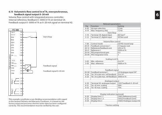
6.15 Volumetric fl ow control in m³/h, oversynchronous, feedback signal output 0–20 mAVolume fl ow control with integrated process controller.Internal reference, feedback 0–5000 m3/h on terminal 54. Feedback output 0–5000 m3/h as 0–20 mA signal on terminal 42.
This example constitutes a non-binding recommendation with regard
Relevant parametersPar. Function Setting0-02 Hz/rpm selection [1] Hz4-14 Max. frequency [Hz] 72 Hz
Start/Stop5-10 Terminal 18: digital input [8] Start*5-12 Terminal 27: digital input [0] Not used
Volume fl ow control1-00 Control mode [3] PID closed loop
20-01 Feedback conversion 1 [1] Square root20-12 Reference/feedback unit [25] m3/h20-21 Reference 1 2500 m3/h20-93 PID proportional gain 0.520-94 PID integration time 2
Scaling in m3/h3-02 Min. reference 0 m3/h*3-03 Max. reference 5000 m3/h
Feedback signal20-00 Feedback terminal 1 [2] Analogue input 54*6-24 Ter. 54 scale min. ref/feedback 0 m3/h*6-25 Ter. 54 scale max. ref/feedback 5000 m3/h
Analogue output6-50 Terminal 42: analogue output [102] Feedback 0–20 mA6-51 Ter. 42 min. scaling 50%6-52 Ter. 42 max. scaling 75%
Display indication (optional)0-20 Display line 1.1 [1601] Reference [unit]0-22 Display line 1.3 [1652] Feedback [unit]0-24 Display line 3 [1665] Analogue output 42
* Factory setting
Feedback signal
Feedback signal 0–20 mA
Start/Stop
*Saf
e st
op
as
op
tio
nRe
lay
2Re
lay
1
6
This example constitutes a non-binding recommendation with regard to the General Delivery and Warranty Conditions. It is based on the factory setup and presumes that the motor data has been confi gured correctly. This recommendation must be verifi ed by the user.
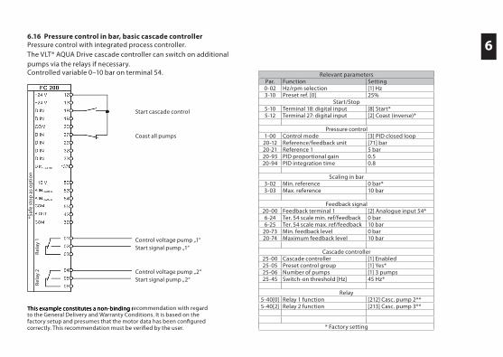
6.16 Pressure control in bar, basic cascade controllerPressure control with integrated process controller.The VLT® AQUA Drive cascade controller can switch on additional pumps via the relays if necessary.Controlled variable 0–10 bar on terminal 54.
This example constitutes a non-binding recommendation with regard
Relevant parametersPar. Function Setting0-02 Hz/rpm selection [1] Hz3-10 Preset ref. [0] 25%
Start/Stop5-10 Terminal 18: digital input [8] Start*5-12 Terminal 27: digital input [2] Coast (inverse)*
Pressure control1-00 Control mode [3] PID closed loop20-12 Reference/feedback unit [71] bar20-21 Reference 1 5 bar20-93 PID proportional gain 0.520-94 PID integration time 0.8
Scaling in bar3-02 Min. reference 0 bar*3-03 Max. reference 10 bar
Feedback signal20-00 Feedback terminal 1 [2] Analogue input 54*6-24 Ter. 54 scale min. ref/feedback 0 bar6-25 Ter. 54 scale max. ref/feedback 10 bar
20-73 Min. feedback level 0 bar20-74 Maximum feedback level 10 bar
Cascade controller25-00 Cascade controller [1] Enabled25-05 Preset control group [1] Yes*25-06 Number of pumps [1] 3 pumps25-45 Switch-on threshold [Hz] 45 Hz*
Relay5-40[0] Relay 1 function [212] Casc. pump 2**5-40[2] Relay 2 function [213] Casc. pump 3**
* Factory setting
Control voltage pump „1“Start signal pump „1“
Control voltage pump „2“Start signal pump „2“
Start cascade control
Coast all pumps
*Saf
e st
op
as
op
tio
nRe
lay
2Re
lay
1

If you have any questions or need additional assistance, contact your authorised retailer or designated contact person.
The current contact data can be found on the website of the appropriate country or under Contact at www.danfoss.com.
PB.14.H1.02 VLT® is a trademark of Danfoss A/S Produced by KKM 2010.03