QUESTION BANK of Control System VI sem ECE Table/VI sem ECE.pdfMicrosoft Word - QUESTION BANK of...
12
QUESTION BANK RUCHITA GUPTA CONTROL SYSTEM ECE VI SEM UNIT-I 1. Explain open loop & closed loop control systems by giving suitable examples & also highlights their merits & demerits. 2.(a) Determine the overall transfer function (C/R) of the system shown in figure by block diagram reduction technique. (b) Draw the Signal flow graph of the above system & verify the result by using Mason’s gain formula.
-
Upload
nguyendang -
Category
Documents
-
view
217 -
download
2
Transcript of QUESTION BANK of Control System VI sem ECE Table/VI sem ECE.pdfMicrosoft Word - QUESTION BANK of...
QUESTION BANK
RUCHITA GUPTA
CONTROL SYSTEM
ECE VI SEM
UNIT-I
1. Explain open loop & closed loop control systems by giving suitable
examples & also highlights their merits & demerits.
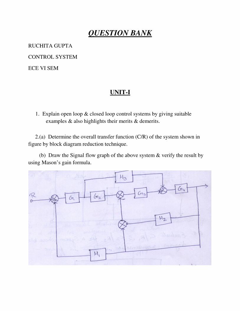
2.(a) Determine the overall transfer function (C/R) of the system shown in
figure by block diagram reduction technique.
(b) Draw the Signal flow graph of the above system & verify the result by
using Mason’s gain formula.

3. Use Mason’s gain formula to find the transfer function C(s)/R(s) for the
signal flow graph shown below-
4. Find the transfer function of the electrical network shown in figure-

5. Evaluate C1/R1 & C2/R2 for a system whose block diagram representation is
shown in figure-
6. Determine C(s)/R(s)-

7. Draw signal flow graph for the following equations-
(i) y2 = a1*dy1/dt
(ii) y3 = d2y2/dt
2 + dy1/dt – y1
(iii) d2y/dx
2 + 2/3 * dy/dx + 11/2 * y = x
UNIT-II
1. Obtain the nodal equations for the system shown in figure & draw its
analogous electrical network-
2. A servo system for the position control of a rotable mass is stabilized by
viscous friction damping which is three-quarters of that is needed for critical
damping. The undamped natural frequency of the system in 12Hz. Derive an
expression for the output of the system, if the input control is suddenly
moved to a new position, being initially at rest. Hence, find the maximum
overshoot.

3. Measurements conducted on a servomechanism show the system response
to be C(t) = 1+0.2 e-60t
– 1.2 e-10t
, when subjected to a unit step input, obtain
the expression for closed loop transfer function, the damping ratio &
undamped natural frequency of oscillations.
4. The transfer function of a control system is given by G(s) = 1/(1+sT)2 .
Show that if the input is a step displacement, the output will complete
98.26% of the step in 6T seconds for critical damping.
5. For a unity feedback system whose open loop transfer function is
G(s) = 50/(1+0.1s)(1+2s) , find the position, velocity & acceleration error
constants.
6. A feedback control system is described as
G(s) = 50/s(s+2)(s+5) , H(s) = 1/s
For a unit step input, determine the steady state error constants & errors.
7. The closed loop transfer function of a unity feedback control system is
given by-
C(s)/R(s) = 10/(s2+4s+5)
Determine
(i) Damping ratio
(ii) Natural undammed resonance frequency
(iii) Percentage peak overshoot
(iv) Expression for error response.
UNIT-III
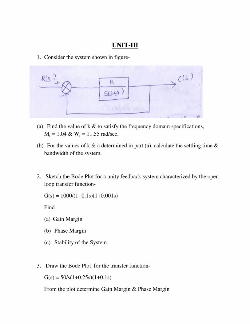
1. Consider the system shown in figure-
(a) Find the value of k & to satisfy the frequency domain specifications,
Mr = 1.04 & Wr = 11.55 rad/sec.
(b) For the values of k & a determined in part (a), calculate the settling time &
bandwidth of the system.
2. Sketch the Bode Plot for a unity feedback system characterized by the open
loop transfer function-
G(s) = 1000/(1+0.1s)(1+0.001s)
Find-
(a) Gain Margin
(b) Phase Margin
(c) Stability of the System.
3. Draw the Bode Plot for the transfer function-
G(s) = 50/s(1+0.25s)(1+0.1s)
From the plot determine Gain Margin & Phase Margin

4. Draw the Bode Plot for a system having
G(s) H(s) = 100/s(s+1)(s+2)
Find-
(a) Gain Margin
(b) Phase Margin
(c) Gain Crossover freq.
(d) Phase crossover freq.
5. Determine the transfer function whose approximate plot shown in figure-

UNIT-IV
1. With the help of Routh Hurwitz criterion comments upon the stability of the
system having the following characteristic equation
S6+s
5-2s
4-3s
3-7s
2-4s-4=0
2. (a) The closed loop transfer function of an antenna control system is given
by-
T(s) = k/(s4+6s
3+30s
2+60s+k)
Determine the range in which k must lie for the system to be stable.
(b) How many roots does each of the following polynomials have in the
right half of the s-plane.
(i) s4+2s
3+4s
2+8s+15
(ii) s6+4s
5+11s
4+12s
3+26s
2+84s+16
3. Sketch the root-locus of G(s) = k/(s2+10s+100)
4. The open loop transfer function of a unity gain feedback is given by-
G(s) = k(s+2)/(s4+3s
3+4s
2+2s) , k>=0
(a) Determine all the poles & zeros of G(s).
(b) Draw the root locus.
5. Sketch the polar plot for the following transfer function-
G(s) = 1/s(s+1)
6. Investigate the stability of a closed loop system with the following open loop
transfer function using Nyquist stability criterion-
G(s) H(s) = k(s+3)/s(s-1)
7. Sketch the Nyquist Plot for a unity feedback system having open-loop
transfer function given by-
G(s) = k/s(1+s)(1+2s)(1+3s)
Determine the range of values of k for which the system is stable.
UNIT-V
1. Derive the Expression for the Transfer function from the state model

2. Construct signal flow graph & state model for a system whose transfer
function is-
T(s) = (s2+3s+3)/(s
3+2s
2+3s+1)
3. A system is described by-
Find the T.F. & construct the signal flow graph.
4. Draw state transition signal flow graph for the following system-
d2c(t)/dt
2 + 6dc(t)/dt + 5 c(t) = 2 dr(t)/dt + r(t)
by means of
(i) Parallel decomposition
(ii) Cascade decomposition
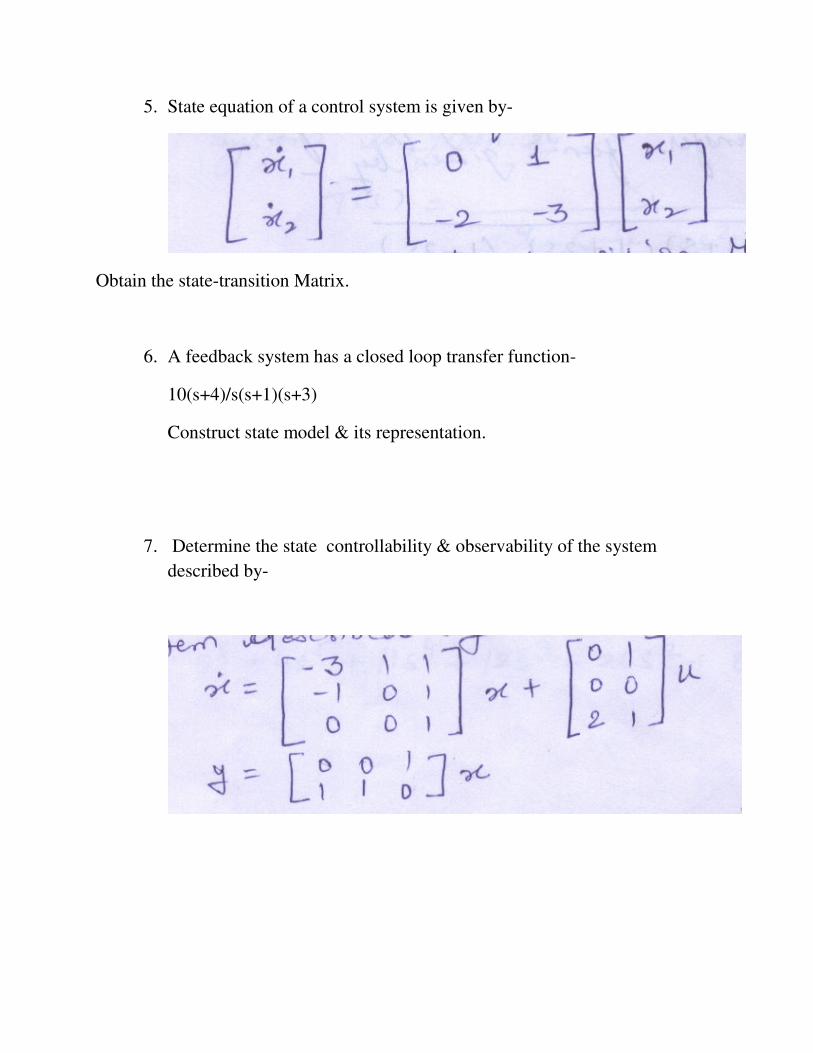
5. State equation of a control system is given by-
Obtain the state-transition Matrix.
6. A feedback system has a closed loop transfer function-
10(s+4)/s(s+1)(s+3)
Construct state model & its representation.
7. Determine the state controllability & observability of the system
described by-

----------------------------------------****----------------------------------------