Question Bank
394
SYSTEMS OF TRAIN WORKING QUESTION BANK (SIGNAL) (Subjective Questions) Q1: With the help of a sketch, define station limits for "B" class stations equipped with Two Aspect signalling on single line and double line sections. 2.41 STATION SECTION means that section of station limits (a) At a class `B' station provided with two-aspect signals, which is included - (i)On a double line, between Home Signal and the Last Stop Signal of the Station in either direction; OR (ii) On a single line – Between the Shunting Limit Boards or Advanced Starters (if any), or Between the Home Signals if there are no Shunting Limit Boards or Advanced Starters, or Between the outermost facing points, if there are no Home Signals or Shunting Limit Boards or Advanced Starters; (b) At a class `B' station provided with manually operated multiple-aspect or modified lower quadrant signals, which is included -- (i)On a double line -- Between the outermost facing points and the last Stop Signal of the station in either direction, or Between the Block Section Limit Board, where provided, and the last Stop Signal of the station in either direction, OR (ii) On a single line - Between the Shunting Limit Boards or Advanced Starters (if any), or Between the outermost facing points if there are no Shunting Limit Board or Advanced Starters. Q2: What are the classifications of stations in Indian Railways? 14.1 For the purpose of rules, stations in absolute block system are classified as shown below.
-
Upload
bhavani-prasad-banda -
Category
Documents
-
view
432 -
download
30
Transcript of Question Bank
SYSTEMS OF TRAIN WORKING
QUESTION BANK (SIGNAL) (Subjective Questions)
Q1: With the help of a sketch, define station limits for "B" class stations equipped with Two Aspect signalling on single line and double line sections.
2.41 STATION SECTION means that section of station limits
(a) At a class `B' station provided with two-aspect signals, which is included -
(i) On a double line, between Home Signal and the Last Stop Signal of the Station in either direction;
OR(ii) On a single line –
Between the Shunting Limit Boards or Advanced Starters (if any), or
Between the Home Signals if there are no Shunting Limit Boards or Advanced Starters, or
Between the outermost facing points, if there are no Home Signals or Shunting Limit Boards or Advanced Starters;
(b) At a class `B' station provided with manually operated multiple-aspect or modified lower quadrant signals, which is included --
(i) On a double line --
Between the outermost facing points and the last Stop Signal of the station in either direction, or
Between the Block Section Limit Board, where provided, and the last Stop Signal of the station in either direction, OR
(ii) On a single line -
Between the Shunting Limit Boards or Advanced Starters (if any), or
Between the outermost facing points if there are no Shunting Limit Board or Advanced Starters.
Q2: What are the classifications of stations in Indian Railways?14.1 For the purpose of rules, stations in absolute block system are classified as shown below.
(a) CLASS `A' STATIONS: Where line clear may not be given for a train, unless the line on which it is intended to receive the train is clear for atleast 400 metres beyond the Home Signal, or upto the starter.
(b) CLASS `B' STATIONS: Where line clear may be given for a train before the line has been clear for the reception of the train within the station section.
(c) CLASS `C' STATIONS OR BLOCK HUTS: Where permission to approach may not be given for a train unless the whole of the last proceeding train has passed complete at least 400 metres beyond the Home Signal and is continuing its journey. This will also include an Intermediate Block Post.
SYSTEMS OF TRAIN WORKING
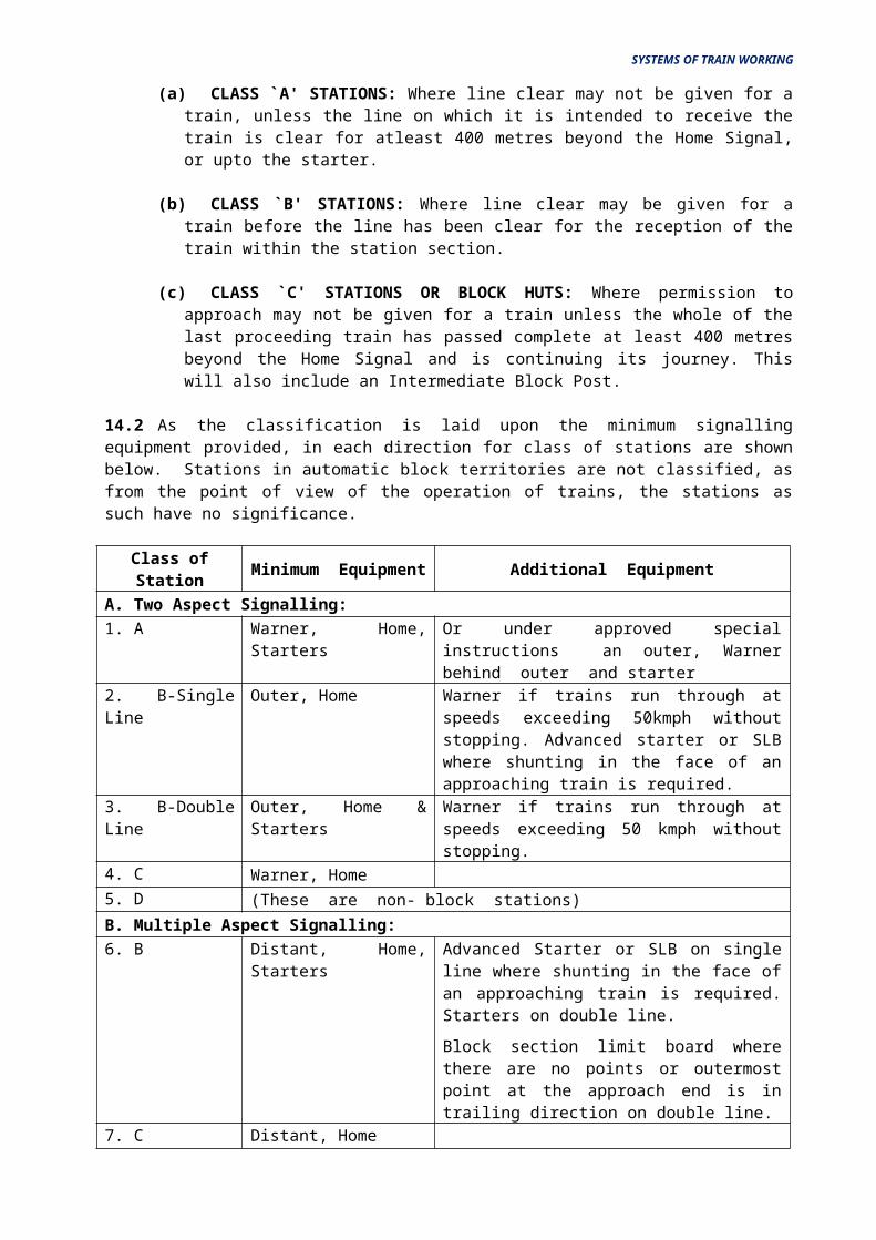
14.2 As the classification is laid upon the minimum signalling equipment provided, in each direction for class of stations are shown below. Stations in automatic block territories are not classified, as from the point of view of the operation of trains, the stations as such have no significance.
Class of Station Minimum Equipment Additional Equipment
A. Two Aspect Signalling:1. A Warner, Home, Starters Or under approved special instructions an
outer, Warner behind outer and starter
2. B-Single Line Outer, Home Warner if trains run through at speeds exceeding 50kmph without stopping. Advanced starter or SLB where shunting in the face of an approaching train is required.
3. B-Double Line Outer, Home & Starters Warner if trains run through at speeds exceeding 50 kmph without stopping.
4. C Warner, Home5. D (These are non- block stations)
B. Multiple Aspect Signalling:6. B Distant, Home, Starters Advanced Starter or SLB on single line where
shunting in the face of an approaching train is required. Starters on double line.
Block section limit board where there are no points or outermost point at the approach end is in trailing direction on double line.
7. C Distant, Home
C. Modified Lower Quadrant:8. B Distant, Home, Warner
below main Home & Starters
MLQ Signalling may be used only where it is expressly sanctioned by a special order of the Rail Board
9. C Distant & Home
Q3: What do you mean by "Read Back Technique" in Railway signalling? Please cite few examples of this technique being used in your Railway.
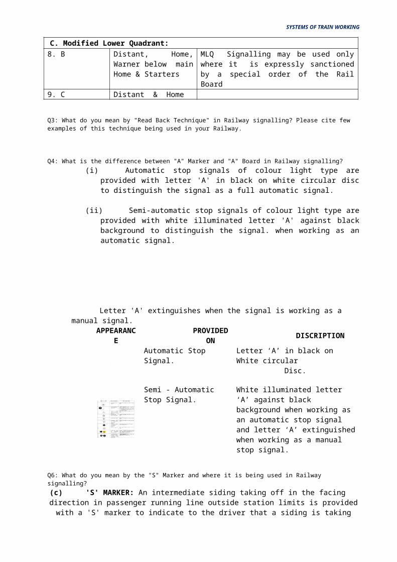
Q4: What is the difference between "A" Marker and "A" Board in Railway signalling?(i) Automatic stop signals of colour light type are provided with letter 'A' in black on
white circular disc to distinguish the signal as a full automatic signal.
(ii) Semi-automatic stop signals of colour light type are provided with white illuminated letter 'A' against black background to distinguish the signal. when working as an automatic signal.
SYSTEMS OF TRAIN WORKING
Letter 'A' extinguishes when the signal is working as a manual signal.APPEARANC
EPROVIDED
ONDISCRIPTION
Automatic Stop Signal. Letter ‘A’ in black on White circular Disc.
Semi - Automatic Stop Signal.
White illuminated letter ‘A’ against black background when working as an automatic stop signal and letter ‘A’ extinguished when working as a manual stop signal.
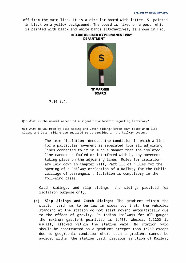
Q6: What do you mean by the "S" Marker and where it is being used in Railwaysignalling?
(c) 'S' MARKER: An intermediate siding taking off in the facing direction in passenger running line outside station limits is provided with a 'S' marker to indicate to the driver that a siding is taking off from the
main line. It is a circular board with letter 'S' painted in black on a yellow background. The board is fixed on a post, which is painted with black and white bands alternatively as shown in Fig. 7.16 (c).
Q5: What is the normal aspect of a signal in Automatic signaling territory?
Q6: What do you mean by Slip siding and Catch siding? Write down cases when Slipsiding and Catch siding are required to be provided in the Railway system.
The term `Isolation' denotes the condition in which a line for a particular movement is separated from all adjoining lines connected to it in such a manner that the isolated line cannot be fouled or interfered with by any movement taking place on the adjoining lines. Rules for isolation are laid down in Chapter VIII, Part III of “Rules for the opening of a Railway or Section of a Railway for the Public carriage of passengers”. Isolation is compulsory in the following cases.
Catch sidings, and slip sidings, and sidings provided for isolation purpose only.
SYSTEMS OF TRAIN WORKING
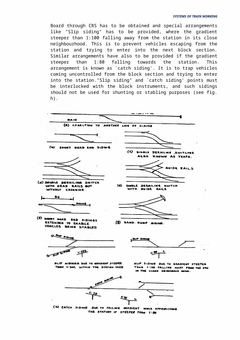
(d) Slip Sidings and Catch Sidings: The gradient within the station yard has to be low in order to, that, the vehicles standing at the station do not start moving automatically due to the effect of gravity. On Indian Railways for all gauges the maximum gradient permitted is 1:400, whereas 1:1200 is usually allowed within the station yard. No station yard should be constructed on a gradient steeper than 1:260 except due to geographic condition where such a gradient cannot be avoided within the station yard, previous sanction of Railway Board through CRS has to be obtained and special arrangements like "Slip siding" has to be provided, where the gradient steeper than 1:100 falling away from the station in its close neighbourhood. This is to prevent vehicles escaping from the station and trying to enter into the next block section. Similar arrangements have also to be provided if the gradient steeper than 1:80 falling towards the station. This arrangement is known as `catch siding'. It is to trap vehicles coming uncontrolled from the block section and trying to enter into the station."Slip siding" and `catch siding' points must be interlocked with the block instruments, and such sidings should not be used for shunting or stabling purposes (see fig. h).
SYSTEMS OF TRAIN WORKING
METHODS OF ISOLATION
Q7: In Indian Railways, what are the systems of train working adopted? Please alsomention the name of the most widely used system on Indian Railways.
SYSTEMS OF TRAIN WORKING
In Indian Railways, six systems of train working are adopted and they are
(a) The Absolute Block System
(b) The Automatic Block System
(c) The Following Trains System
(d) The Pilot Guard System
(e) The Train Staff and Ticket System
(f) The One Train Only System
Out of the above six systems of train working, the Absolute Block System and the Automatic Block System only shall be used, unless the adoption of other systems are especially permitted by the Railway Board.
Q8: Please prepare the locking table for Lever numbers 1, 3, 4, 6 & 7 of the followingdiagram: -
Q9: What are the essential requirements of the Absolute Block System?(a) Para 8.01 of General Rules stipulates the essential requirements of the system as under
“Where trains are worked on the Absolute Block System”.
(i) no train shall be allowed to leave a block station unless Line clear has been received from the block station in advance, and
(ii) On double lines, such line clear shall not be given unless the line is clear not only upto the first stop signal at the block station at which such line clear is given but also for an adequate distance beyond it.
(iii) On single lines, such Line Clear shall not be given unless the line is clear of trains running in the same direction not only upto the first stop signal at the block station at which such Line Clear is given but also for an adequate distance beyond it, and is clear of trains running in the direction towards the block station to which such Line Clear is given.
SYSTEMS OF TRAIN WORKING
(b) The General Rule further states that the adequate distance referred above shall not be less than 400 metres in case of 2 Aspect signalling and 180 metres in Multiple Aspect Upper Quadrant Semaphore Signalling or Colour Light Signalling and modified lower quadrant signalling. This is generally called the "Block Overlap" in signalling parlance. This distance can be reduced in case of necessity but this can be done, only under "approved special instructions" which means that sanction of Commissioner of Railway Safety is required to be obtained for reduction in the adequate distance.
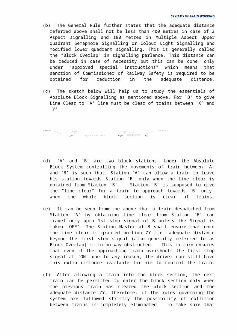
(c) The sketch below will help us to study the essentials of Absolute Block Signalling as mentioned above. For `B' to give Line Clear to `A' line must be clear of trains between `X` and `Y'.
(d) `A' and `B' are two block stations. Under the Absolute Block System controlling the movements of train between `A' and `B' is such that, Station `A' can allow a train to leave his station towards Station `B' only when the line clear is obtained from Station `B'. Station `B' is supposed to give the "line clear" for a train to approach towards `B' only, when the whole block section is clear of trains.
(e) It can be seen from the above that a train despatched from Station `A' by obtaining line clear from Station `B' can travel only upto 1st stop signal of B unless the Signal is taken `OFF'. The Station Master at B shall ensure that once the line clear is granted portion ZY i.e. adequate distance beyond the first stop signal (also generally referred to as Block Overlap) is in no way obstructed. This in turn ensures that even if the approaching train overshoots the first stop signal at `ON' due to any reason, the driver can still have this extra distance available for him to control the train.
(f) After allowing a train into the block section, the next train can be permitted to enter the block section only when the previous train has cleared the block section and the adequate distance ZY, therefore, if the rules governing the system are followed strictly the possibility of collision between trains is completely eliminated. To make sure that the Station Masters on both sides are able to follow the rules, provision of communication between stations under this system is compulsory. An additional aids to Station Master, Block Instruments, Last Vehicle Check Device etc., also may be provided according to the requirements.
(g) The conditions for granting line clear are given in Chapter 8 of General Rules as detailed below:
(i) Rule No.8.02: Conditions for granting Line Clear at Class `A' Station
(ii) Rule No.8.03: Conditions for granting Line Clear at Class `B' Station
(iii) Rule No.8.04: Conditions for granting Line Clear at Class `C' Station
(h) In all the above cases, two most important points beside other things are stressed. They are
(i) The whole of the last preceding train has arrived complete; an
(ii) All necessary signals have been put back to `ON' behind the said train

CLASSIFICATION
(i) The arrival of a complete train is checked either by physical verification (L.V. Board or Tail Lamp) or by provision of a last vehicle check device or by having continuous track circuits in the entire block section or by having Axle Counters in the Block section or by any other approved means.
(j) With regard to ensuring all necessary signals have been put back to `ON' after the arrival of a train, these are proved by certain relays which ensure that the signals have been restored to `ON' position before closing of the Block Instrument after the arrival of the train.
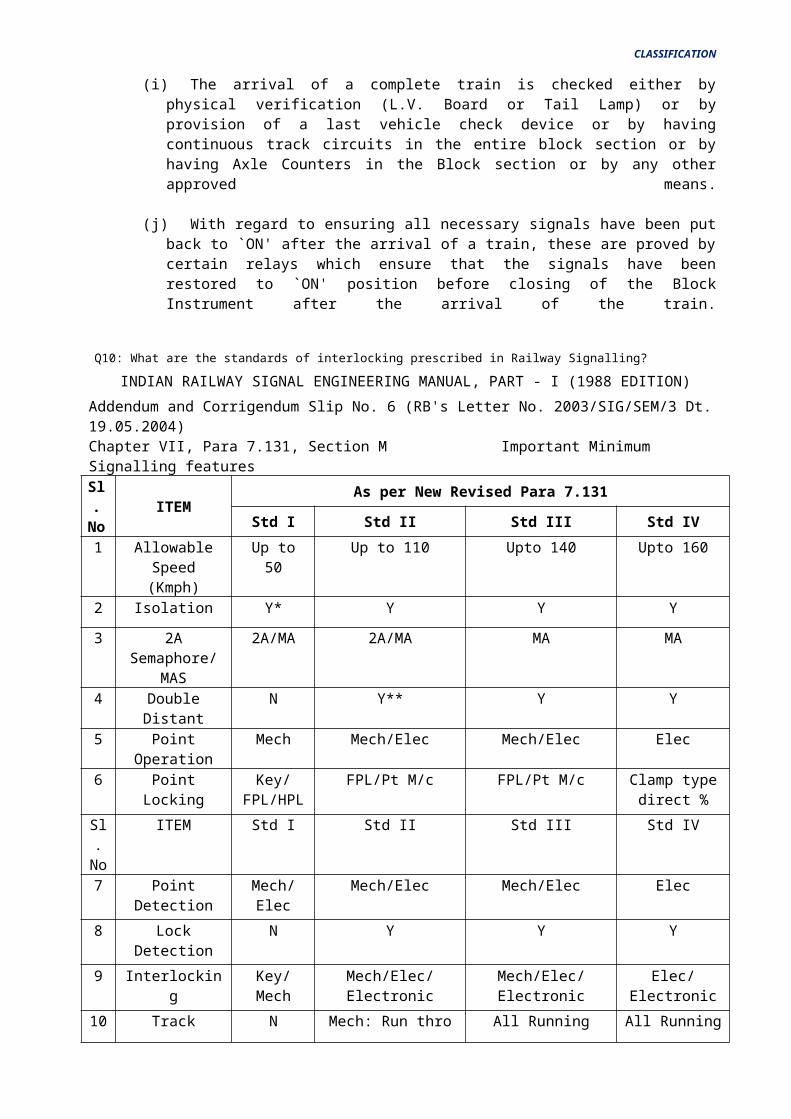
Q10: What are the standards of interlocking prescribed in Railway Signalling?
INDIAN RAILWAY SIGNAL ENGINEERING MANUAL, PART - I (1988 EDITION)
Addendum and Corrigendum Slip No. 6 (RB's Letter No. 2003/SIG/SEM/3 Dt. 19.05.2004)
Chapter VII, Para 7.131, Section M Important Minimum Signalling features
Sl.No
ITEMAs per New Revised Para 7.131
Std I Std II Std III Std IV
1 Allowable Speed (Kmph)
Up to 50 Up to 110 Upto 140 Upto 160
2 Isolation Y* Y Y Y
3 2A Semaphore/ MAS
2A/MA 2A/MA MA MA
4 Double Distant N Y** Y Y
5 Point Operation Mech Mech/Elec Mech/Elec Elec
6 Point Locking Key/FPL/HPL
FPL/Pt M/c FPL/Pt M/c Clamp type direct %
Sl.No
ITEM Std I Std II Std III Std IV
7 Point Detection Mech/Elec Mech/Elec Mech/Elec Elec
8 Lock Detection N Y Y Y
9 Interlocking Key/Mech Mech/Elec/Electronic Mech/Elec/Electronic Elec/Electronic
10 Track Circuiting N Mech: Run thro linesElec/Electronic: All
RLs
All Running Lines All Running Lines
11 Block Working Token Token / SGE # SGE / TC # SGE / TC
12 Preventing SPAD
N N N Y %
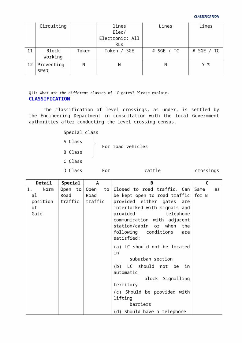
Q11: What are the different classes of LC gates? Please explain.
CLASSIFICATION
CLASSIFICATION
The classification of level crossings, as under, is settled by the Engineering Department in consultation with the local Government authorities after conducting the level crossing census.
Special class
A Class For road vehicles
B Class
C Class
D Class For cattle crossings
Detail Special A B C1. Normal
position ofGate
Open to Road traffic
Open to Road traffic
Closed to road traffic. Can be kept open to road traffic provided either gates are interlocked with signals and provided telephone communication with adjacent station/cabin or when the following conditions are satisfied:
(a) LC should not be located in suburban section
(b) LC should not be in automatic block Signalling territory.
(c) Should be provided with lifting barriers
(d) Should have a telephone connection with the nearest station with exchange of private numbers
(e) Visibility at the level crossing should be good
(f) Should be provided with Whistle boards on either side at adequate distance to enjoin the drivers of approaching trains to give audible warning of the approach of the train to the road users.
(g) As long as the L.C gate is kept open to road traffic, a red flag by day and red light during night should be displayed towards approaching trains on either side of level crossings
Same as for B
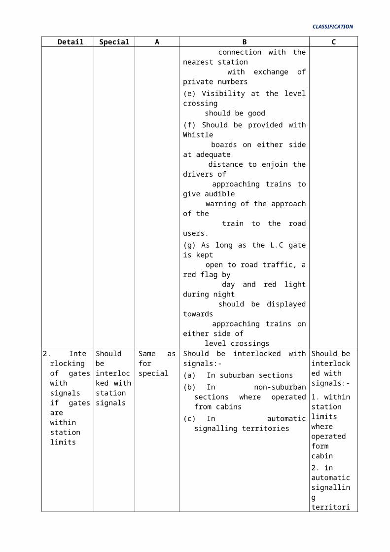
2. Interlocking of gates with signals if gates are within station limits
Should be interlocked with station signals
Same as for special
Should be interlocked with signals:-
(a) In suburban sections
(b) In non-suburban sections where operated from cabins
(c) In automatic signalling territories
Should be interlocked with signals:-
1. within station limits where operated form cabin
2. in automatic signalling
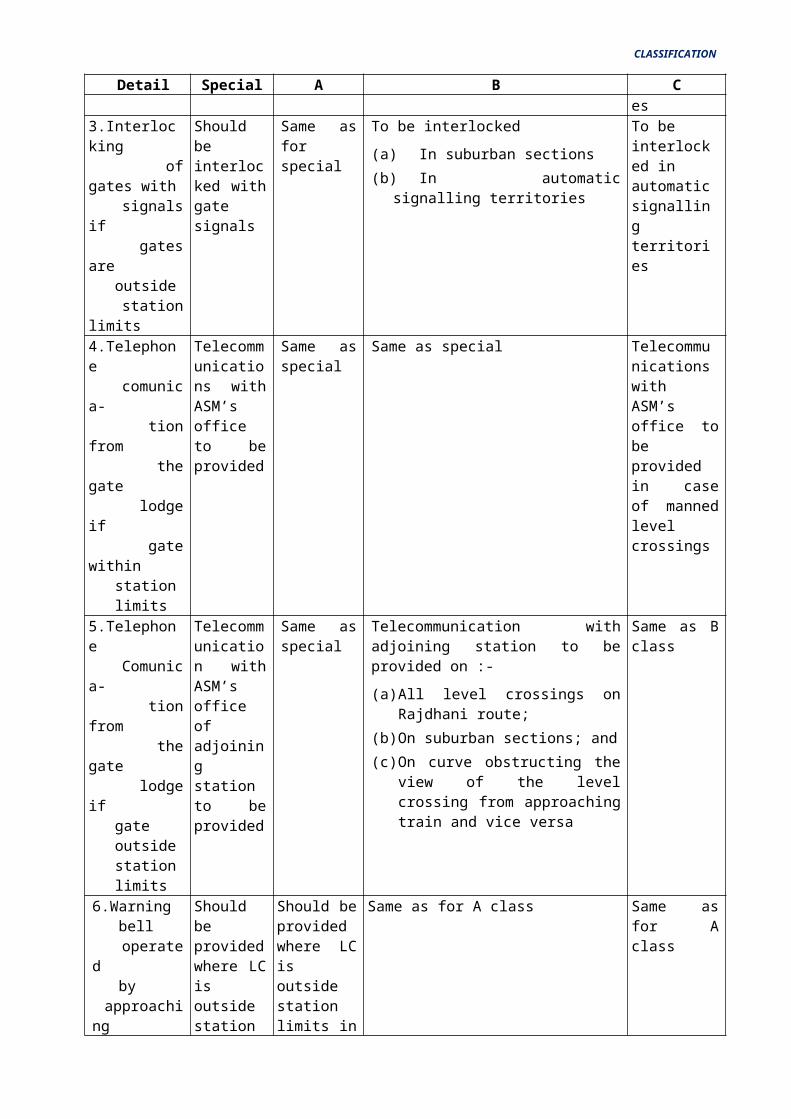
CLASSIFICATION
Detail Special A B Cterritories
3.Interlocking of gates with signals if gates are outside station limits
Should be interlocked with gate signals
Same as for special
To be interlocked
(a) In suburban sections
(b) In automatic signalling territories
To be interlocked in automatic signalling territories
4.Telephone comunica- tion from the gate lodge if gate within station limits
Telecommunications with ASM’s office to be provided
Same as special
Same as special Telecommunications with ASM’s office to be provided in case of manned level crossings
5.Telephone Comunica- tion from the gate lodge if gate outside station limits
Telecommunication with ASM’s office of adjoining station to be provided
Same as special
Telecommunication with adjoining station to be provided on :-
(a) All level crossings on Rajdhani route;
(b) On suburban sections; and
(c) On curve obstructing the view of the level crossing from approaching train and vice versa
Same as B class
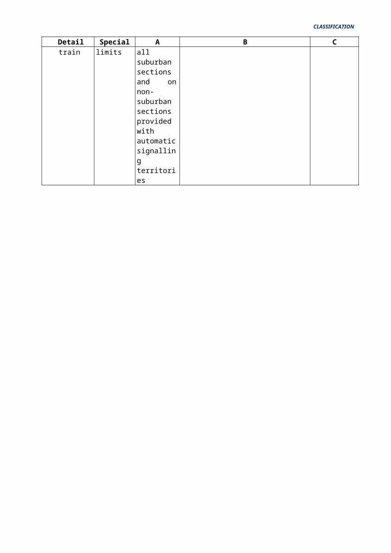
6.Warning bell operated by approaching train
Should be provided where LC is outside station limits
Should be provided where LC is outside station limits in all suburban sections and on non-suburban sections provided with automatic signalling territories
Same as for A class Same as for A class
LOOSE LOCKING BETWEEN POINTS IS FOR SAFETY AND FLEXIBILITY
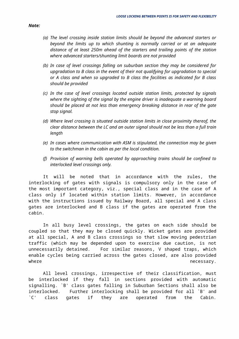
Note:
(a) The level crossing inside station limits should be beyond the advanced starters or beyond the limits up to which shunting is normally carried or at an adequate distance of at least 250m ahead of the starters and trailing points of the station where advanced starters/shunting limit boards are not provided
(b) In case of level crossings falling on suburban section they may be considered for upgradation to B class in the event of their not qualifying for upgradation to special or A class and when so upgraded to B class the facilities as indicated for B class should be provided
(c) In the case of level crossings located outside station limits, protected by signals where the sighting of the signal by the engine driver is inadequate a warning board should be placed at not less than emergency breaking distance in rear of the gate stop signal.
(d) Where level crossing is situated outside station limits in close proximity thereof, the clear distance between the LC and an outer signal should not be less than a full train length
(e) In cases where communication with ASM is stipulated, the connection may be given to the switchman in the cabin as per the local condition.
(f) Provision of warning bells operated by approaching trains should be confined to interlocked level crossings only.
It will be noted that in accordance with the rules, the interlocking of gates with signals is compulsory only in the case of the most important category, viz., special class and in the case of A class only if located within station limits. However, in accordance with the instructions issued by Railway Board, all special and A class gates are interlocked and B class if the gates are operated from the cabin.
In all busy level crossings, the gates on each side should be coupled so that they may be closed quickly. Wicket gates are provided at all special, A and B class crossings so that slow moving pedestrian traffic (which may be depended upon to exercise due caution, is not unnecessarily detained. For similar reasons, V shaped traps, which enable cycles being carried across the gates closed, are also provided where necessary.
All level crossings, irrespective of their classification, must be interlocked if they fall in sections provided with automatic signalling. `B' class gates falling in Suburban Sections shall also be interlocked. Further interlocking shall be provided for all `B' and `C' class gates if they are operated from the Cabin.
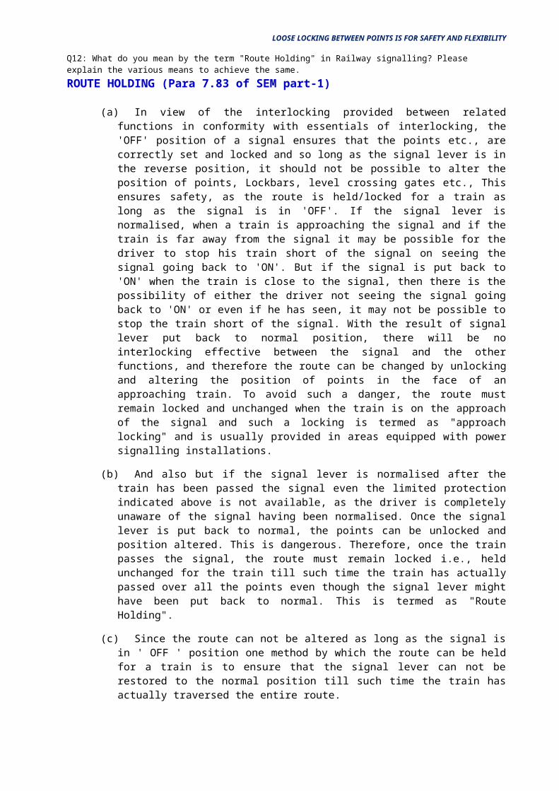
Q12: What do you mean by the term "Route Holding" in Railway signalling? Pleaseexplain the various means to achieve the same.
ROUTE HOLDING (Para 7.83 of SEM part-1)
(a) In view of the interlocking provided between related functions in conformity with essentials of interlocking, the 'OFF' position of a signal ensures that the points etc., are correctly set and locked and so long as the signal lever is in the reverse position, it should not be possible to alter the position of points, Lockbars, level crossing gates etc., This ensures safety, as the route is held/locked for a train as long as the signal is in 'OFF'. If the signal lever is normalised, when a train is approaching the signal and if the train is far away from the signal it may be possible for the driver to stop his train short of the signal on seeing the signal going back to 'ON'. But if the signal is put back to 'ON' when the train is close to the signal, then there is the possibility of either the driver not seeing the signal going back to 'ON' or
LOOSE LOCKING BETWEEN POINTS IS FOR SAFETY AND FLEXIBILITY
even if he has seen, it may not be possible to stop the train short of the signal. With the result of signal lever put back to normal position, there will be no interlocking effective between the signal and the other functions, and therefore the route can be changed by unlocking and altering the position of points in the face of an approaching train. To avoid such a danger, the route must remain locked and unchanged when the train is on the approach of the signal and such a locking is termed as "approach locking" and is usually provided in areas equipped with power signalling installations.
(b) And also but if the signal lever is normalised after the train has been passed the signal even the limited protection indicated above is not available, as the driver is completely unaware of the signal having been normalised. Once the signal lever is put back to normal, the points can be unlocked and position altered. This is dangerous. Therefore, once the train passes the signal, the route must remain locked i.e., held unchanged for the train till such time the train has actually passed over all the points even though the signal lever might have been put back to normal. This is termed as "Route Holding".
(c) Since the route can not be altered as long as the signal is in ' OFF ' position one method by which the route can be held for a train is to ensure that the signal lever can not be restored to the normal position till such time the train has actually traversed the entire route.
(d) The method suggested above may require track circuits over the entire route and an electric lever lock on the signal lever so that it is not possible to normalise the signal lever unless the train has cleared the entire route. Provision of track circuit may not be practicable at all wayside stations, in view of the heavy expenditure involved and therefore, some other method must be employed to hold the route. This is achieved with the help of the Lockbars and interlocking between successive Lockbars.
(e) Lockbars are working in conjunction with facing point locks, which are used to lock the points, once the Lockbar lever is operated, the points get locked at site in the position in which it was lying prior to the operation of the Lockbar and the point position can not be altered unless the point is first unlocked. For unlocking the point, the Lockbar lever has to be normalised which is not possible when a train is on that Lockbar. Therefore if the Lockbar can not be normalised, the point can not be unlocked and its position would remain unaltered. This gives us an application by which the route can be held.
(f) Referring to Fig. 2.8.5 points 8 and 11 have to be first locked in the normal position by operating Lockbar levers 7 and 10 to reverse before the signal No.3 for main line is taken 'OFF'. Once the signal lever is operated to reverse, the Lockbar levers get back locked and can not be put back to normal. This protection is available so long as the signal lever has not been normalised.
(g) But once the signal lever is normalised, the interlocking between the signal lever and the Lockbar levers is released and therefore, the point position can be changed after unlocking them. But, if the distance between the signal No.3 and the point No.8 can be kept restricted such that before the cabinman has had time to normalise the Lockbar lever No.7 (after normalising the signal lever), the train has already been on the Lockbar No.7, then, even though the interlocking on lever No.7 is free, it is not possible to normalise the Lockbar as the train is physically on it. If the Lockbar can not be normalised, the position of the point also can not be changed. This way point No.8 is held for the train even though the signal lever No.3 has been put back to normal.
(h) But how can the route holding be extended to point No.11 which is a little away from signal No.3? Because of the longer distance involved, the cabin man, after normalising the signal lever, may have enough time to normalise Lockbar lever No. 10 which is locking point No.11. Once the Lockbar lever is normalised, the point position can be changed. To prevent this,
LOOSE LOCKING BETWEEN POINTS IS FOR SAFETY AND FLEXIBILITY
interlocking between successive Lockbars in the route is introduced in such a way that the lever of Lockbar in advance can not be normalised unless the lever of Lockbar in rear has first been normalised. In the present situation, the Lockbar lever No.10 can not be normalised unless Lockbar lever No.7 is normalised which is not possible as long as a train is on lockbar 7. Now if we restrict the distance between those two successive points and the successive Lockbars, such that, by the time the cabin man is able to normalise Lockbar lever No.10 after the train has cleared the Lockbar No.7 and 7 is normalised, the train already would have reached on Lockbar 10, then the point No.11 is also held by the train. By extending similar interlocking between all the Lockbars, all the facing points in the route advance of the train can be held till the train actually clears them.
(i) The time interval that lapses from the instant the signal lever has been put back to normal to the instant when the train actually occupies the first Lockbar, or the time interval that lapses between the instant the train clears the Lockbar in rear and the instant it occupies the Lockbar immediately in advance is the crucial factor in the satisfactory working of the above method. In other words the distance between the signal and the first facing point and the distance between successive facing points has to be limited and Para 7.83 of Signal Engineering Manual 1988 specifies that this distance should not be more than 180 Meters.
(j) If the distance becomes more than 180 Meters then an additional lockbar called Lock Retaining Bar (sometimes called holding bar) has to be introduced between the signal and the first facing point or between two successive facing points. In such cases, the distance between any two adjacent functions i.e., the signal and the Lock Retaining Bar and the Lockbar of the facing point is not more than 180 Meters Interlocking also shall be provided between successive Lockbars in a route such that the Lockbar in advance can not be normalised unless the Lockbar/Lock Retaining Bar in rear has been normalised. It will be seen later on that, this is the same relationship as Lockbar in rear released by Lockbar in advance.
(k) If the system of working is such that enough time would have lapsed between the instant the cabin man puts back the signal to ON to the instant when he is in a position to operate the point and during this time if the train would have actually cleared the route, then, special arrangements for holding the route are not necessary. An example of this type of working is the Route Key Method employed in Double Wire Cabins or Standard-I interlocking with locally operated key locked points.
(l) The factors by which route holding is achieved (in the above methods) are:-
(i) The Interlocking between the signal and the facing points and the Lockbars, results the points can not be unlocked and altered unless the signal lever is normalised.
(ii) The distance between the signal and the first facing point and the distance between successive facing points (which is limited to 180 Meters) and the interlocking between successive Lockbars due to which it is ensured that the cabinman can not unlock any facing point in the face of an approaching train even though concerned signal has been put back to normal behind the train.
(iii) The very purpose of the lockbar on the facing point is such that the point can not be unlocked when the train is passing over the Lockbars.
(iv) Where the distance from the signal to the first facing point or from one facing point to next facing point is more than 180 Meters provision of lock retaining bar/bars ensures route holding. In the case of successive facing points, the Lockbar of a facing point in the rear serves as a lock-retaining bar for the facing point Lockbar in advance of it. This is ensured by interlocking between successive Lockbars.
LOOSE LOCKING BETWEEN POINTS IS FOR SAFETY AND FLEXIBILITY
(m) The following are the provisions of 7.83 SEM part-1 in this connection
(i) The signal must be located as close as possible to the points which it protects.
(ii) Where the signal cannot be located within 180 Meters from the first facing point which it protects, and where the distance between successive facing points is more than 180 Meters special methods of route holding must be employed as indicated in the Paras above.
(iii) Such methods are unnecessary if the method of working is such that the sufficient time lapses between the instant the signal lever was put back to normal and to the instant that the point levers are in a position to be operated and by that time train must have actually cleared the route.
(n) At a station where trains run through at speeds more than 50 KMPH, such arrangements are also required to hold the route are also required in case of trailing points situated more than 180 Meters from the signal controlling them. However such arrangements are not required if the points are locked in either position by the signal in advance 7.83(2) of SEM part-1
Q13: What do you mean by "Loose" and "Tight" locking in Railway signalling? Pleaseexplain with examples.
CHAPTER – 10: TIGHT AND LOOSE LOCKING
10.1 It is seen from the proceeding chapter that by using a clutch lever interlocking can be extended right up to the function. The integrity of the wire transmission can not be taken for granted and therefore there is a possibility of the function not responding to the action of the lever. The lever and its function may be out of correspondence with each other.
10.2 When a clutch lever is used and when there is out of correspondence between the lever and its function or when the transmission is defective, the lever drum alone is made to rotate and the lever is said to trip. The rotation of the drum results in a stroke on the locking plunger.
10.3 The stroke on the locking plunger can be caused either by the tripping of the lever if the lever happens to be a clutch lever or by the operation of the lever, the stroke in the two cases being 1/2" (12mm) and 11/2 " (40 mm) respectively. As the movement of the plunger can be made use of to lock another function, the movement due to the out of correspondence between the function and the lever can also be used to lock another function, i.e., the interlocking is extended right up to the function.
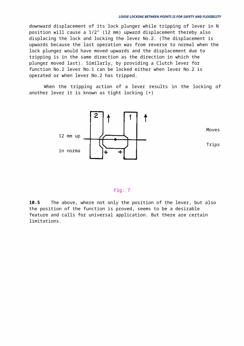
10.4 For example, let the locking relationship between two levers 1 and 2 be such that 1 locks 2. With the transmission of lever No.1 becoming defective, it may so happen that while lever No.1 is in the normal position the function No.1 may not be in normal position. It is desirable to lock lever No.2 in normal position if either the lever No.1 is not in normal position or the function No.1 is not in normal position. To achieve this, a Clutch lever has to be provided for function No.1. In this case in a situation when lever No.1 is in normal position and function No.1 is not in normal position lever No.1 would trip causing a tripping stroke on plunger No.1, which can be made use of to lock lever No.2. In the notes on double wire, it has been explained that the stroke on the plunger due to tripping action is in the same direction in which the plunger moved last. In figure No.7 operation of lever No.1 from N to R, causes a 1 1/2"(40 mm) downward displacement of its lock plunger while tripping of lever in N position will cause a 1/2" (12 mm) upward displacement thereby also displacing the lock and locking the lever No.2. (The displacement is upwards because the last operation was from reverse to normal when the lock plunger
LOOSE LOCKING BETWEEN POINTS IS FOR SAFETY AND FLEXIBILITY
would have moved upwards and the displacement due to tripping is in the same direction as the direction in which the plunger moved last). Similarly, by providing a Clutch lever for function No.2 lever No.1 can be locked either when lever No.2 is operated or when lever No.2 has tripped.
When the tripping action of a lever results in the locking of another lever it is known as tight locking (+)
1 X 2 + Moves 12 mm up when
2 X 1 + Trips in normal
Fig. 7
10.5 The above, where not only the position of the lever, but also the position of the function is proved, seems to be a desirable feature and calls for universal application. But there are certain limitations.
FUNCTION OF PCB'S IN FTG-S FRAME
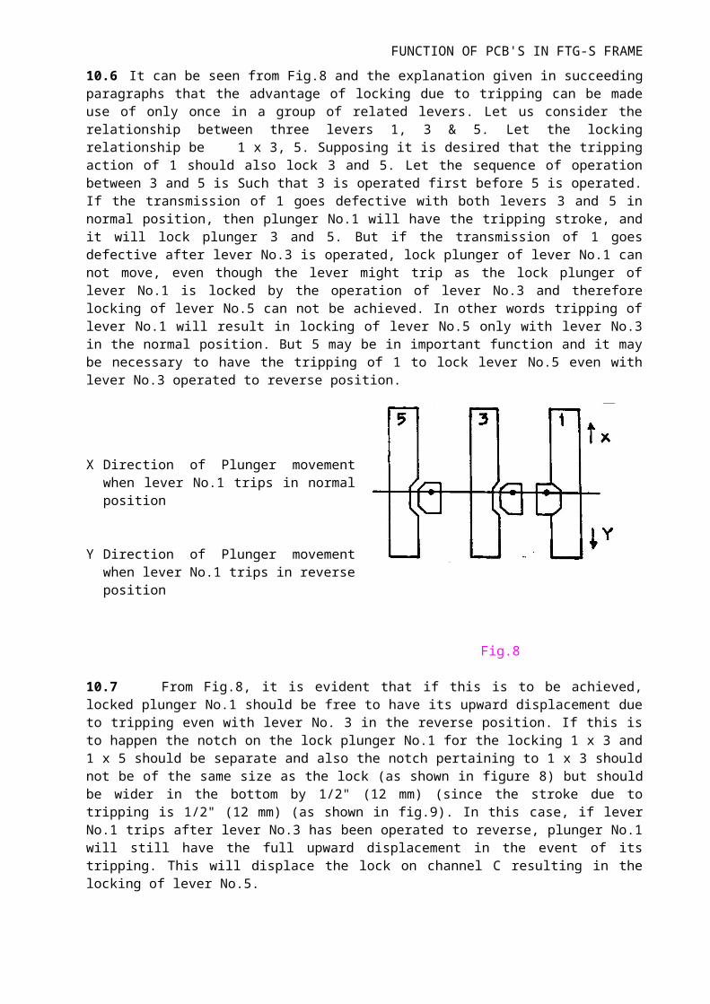
10.6 It can be seen from Fig.8 and the explanation given in succeeding paragraphs that the advantage of locking due to tripping can be made use of only once in a group of related levers. Let us consider the relationship between three levers 1, 3 & 5. Let the locking relationship be 1 x 3, 5. Supposing it is desired that the tripping action of 1 should also lock 3 and 5. Let the sequence of operation between 3 and 5 is Such that 3 is operated first before 5 is operated. If the transmission of 1 goes defective with both levers 3 and 5 in normal position, then plunger No.1 will have the tripping stroke, and it will lock plunger 3 and 5. But if the transmission of 1 goes defective after lever No.3 is operated, lock plunger of lever No.1 can not move, even though the lever might trip as the lock plunger of lever No.1 is locked by the operation of lever No.3 and therefore locking of lever No.5 can not be achieved. In other words tripping of lever No.1 will result in locking of lever No.5 only with lever No.3 in the normal position. But 5 may be in important function and it may be necessary to have the tripping of 1 to lock lever No.5 even with lever No.3 operated to reverse position.
X Direction of Plunger movement when lever No.1 trips in normal position
Y Direction of Plunger movement when lever No.1 trips in reverse position
Fig.8
10.7 From Fig.8, it is evident that if this is to be achieved, locked plunger No.1 should be free to have its upward displacement due to tripping even with lever No. 3 in the reverse position. If this is to happen the notch on the lock plunger No.1 for the locking 1 x 3 and 1 x 5 should be separate and also the notch pertaining to 1 x 3 should not be of the same size as the lock (as shown in figure 8) but should be wider in the bottom by 1/2" (12 mm) (since the stroke due to tripping is 1/2" (12 mm) (as shown in fig.9). In this case, if lever No.1 trips after lever No.3 has been operated to reverse, plunger No.1 will still have the full upward displacement in the event of its tripping. This will displace the lock on channel C resulting in the locking of lever No.5.
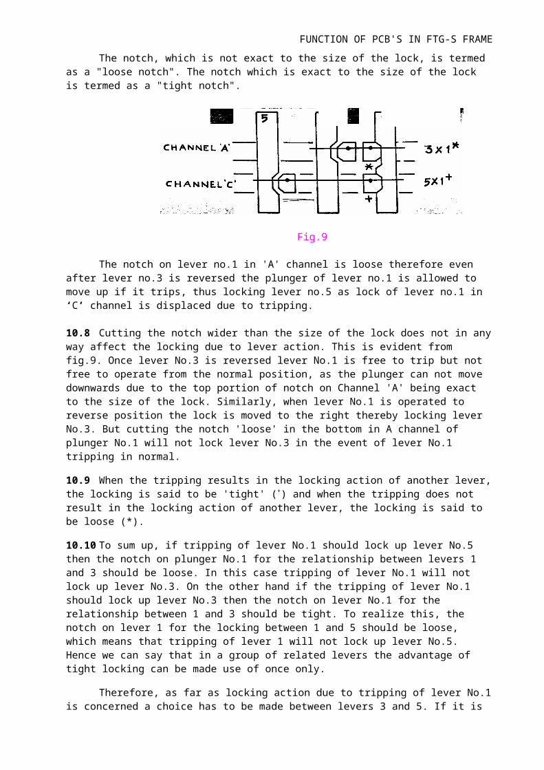
The notch, which is not exact to the size of the lock, is termed as a "loose notch". The notch which is exact to the size of the lock is termed as a "tight notch".
Fig.9
The notch on lever no.1 in 'A' channel is loose therefore even after lever no.3 is reversed the plunger of lever no.1 is allowed to move up if it trips, thus locking lever no.5 as lock of lever no.1 in ‘C’ channel is displaced due to tripping.
FUNCTION OF PCB'S IN FTG-S FRAME
10.8 Cutting the notch wider than the size of the lock does not in any way affect the locking due to lever action. This is evident from fig.9. Once lever No.3 is reversed lever No.1 is free to trip but not free to operate from the normal position, as the plunger can not move downwards due to the top portion of notch on Channel 'A' being exact to the size of the lock. Similarly, when lever No.1 is operated to reverse position the lock is moved to the right thereby locking lever No.3. But cutting the notch 'loose' in the bottom in A channel of plunger No.1 will not lock lever No.3 in the event of lever No.1 tripping in normal.
10.9 When the tripping results in the locking action of another lever, the locking is said to be 'tight' (+) and when the tripping does not result in the locking action of another lever, the locking is said to be loose (*).
10.10 To sum up, if tripping of lever No.1 should lock up lever No.5 then the notch on plunger No.1 for the relationship between levers 1 and 3 should be loose. In this case tripping of lever No.1 will not lock up lever No.3. On the other hand if the tripping of lever No.1 should lock up lever No.3 then the notch on lever No.1 for the relationship between 1 and 3 should be tight. To realize this, the notch on lever 1 for the locking between 1 and 5 should be loose, which means that tripping of lever 1 will not lock up lever No.5. Hence we can say that in a group of related levers the advantage of tight locking can be made use of once only.
Therefore, as far as locking action due to tripping of lever No.1 is concerned a choice has to be made between levers 3 and 5. If it is to be available for lever No.5, it should not have been made use of for lever No.3 and if it has been made use of for lever No.3 it is not to be available for lever No.5. In such cases, the choice normally lies on the lever which is more important for safety.
10.11 Another limitation is brought about due to operational necessity. If safety is not jeopardized, then in the interest of flexibility, loose locking may be provided. As an example consider the relationship between a trailing point in the overlap and a signal. Safety will not be jeopardized even if the signal is taken 'OFF' with the point incorrectly set. The provision of a tight locking in this case will result in a signal failure if the point lever trips due to defective transmission, incorrect setting or some such cause.
Therefore, to prevent a signal failure, loose locking may be provided if safety is not jeopardized.
10.12 Doubt may now arise as to why at all a clutch lever should be provided if the tripping action is not to be made use of. Even though loose locking may be provided for the relationship with certain levers, in view of the two limitations indicated above, there may be certain other levers with which the relationship should be tight, in the interest of safety. In the case considered in Para 10.10 above, the point may be a facing point lying in the portion traveled by a train and governed by another signal and the relationship with this signal has to be a tight relationship as the positions of the point lever and the point function are very important as far as this signal is concerned. Tight locking should be provided in this case. Since the same point requires a loose as well as tight relationship, a clutch lever has to be provided.
10.13 In the case of a direct lever, there is no question of tripping and therefore, there is no choice of 'loose' or 'tight' locking. All the notches in the plunger of a direct lever are exact to the size of the lock.
10.14 A tight locking is indicated by the sign + and loose locking by the sign * in the locking tables and in the locking diagrams. For example, if the relationship between levers 4 and 5 is Such that 4 locks 5 and if tripping of lever No.4 should lock lever No.5 the relationship is expressed as 5 x 4+. Similarly, if the tripping of lever No.4 is not to lock lever No.5, the relationship is expressed as 5 x 4*. The sign +
represents that the notch on lever No.4 is 'tight' and the * represents that the notch on lever No. 4 is 'loose'.* * *Q14: What do you mean by Ballast Resistance? What are the minimum permissiblevalues for the ballast resistance in the station yard and in the Block section?
FUNCTION OF PCB'S IN FTG-S FRAME
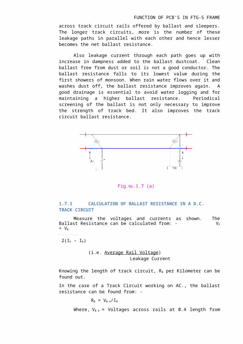
BALLAST RESISTANCE
It is the net resistance of various leakage paths across track circuit rails offered by ballast and sleepers. The longer track circuits, more is the number of these leakage paths in parallel with each other and hence lesser becomes the net ballast resistance.
Also leakage current through each path goes up with increase in dampness added to the ballast dustcoat. Clean ballast free from dust or soil is not a good conductor. The ballast resistance falls to its lowest value during the first showers of monsoon. When rain water flows over it and washes dust off, the ballast resistance improves again. A good drainage is essential to avoid water logging and for maintaining a higher ballast resistance. Periodical screening of the ballast is not only necessary to improve the strength of track bed. It also improves the track circuit ballast resistance.
Fig.No.1.7 (a)
1.7.1 CALCULATION OF BALLAST RESISTANCE IN A D.C. TRACK CIRCUIT
Measure the voltages and currents as shown. The Ballast Resistance can be calculated from: - VF + VR
2(IF – IR)
(i.e. Average Rail Voltage) Leakage Current
Knowing the length of track circuit, RB per Kilometer can be found out.
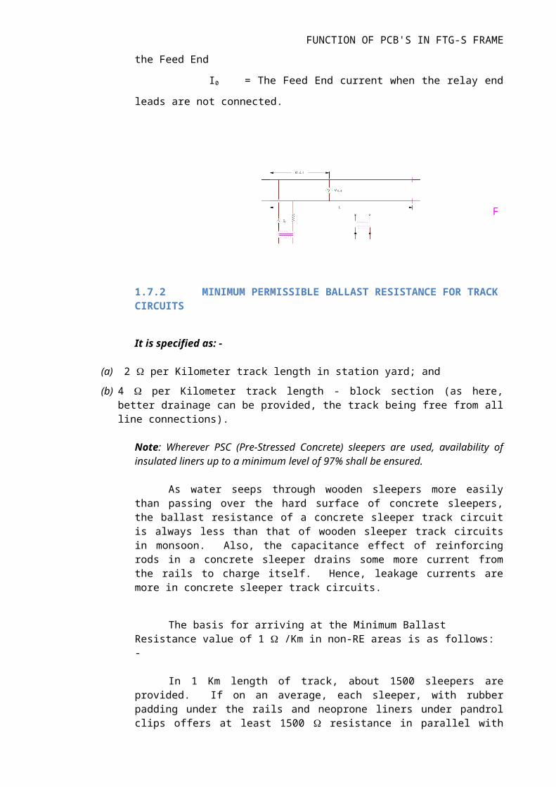
In the case of a Track Circuit working on AC., the ballast resistance can be found from: -
RB = V0.4/I0
Where, V0.4 = Voltages across rails at 0.4 length from the Feed End
I0 = The Feed End current when the relay end leads are not
connected.
FUNCTION OF PCB'S IN FTG-S FRAME
1.7.2 MINIMUM PERMISSIBLE BALLAST RESISTANCE FOR TRACK CIRCUITS
It is specified as: -
(a) 2 per Kilometer track length in station yard; and
(b) 4 per Kilometer track length - block section (as here, better drainage can be provided, the track being free from all line connections).
Note: Wherever PSC (Pre-Stressed Concrete) sleepers are used, availability of insulated liners up to a minimum level of 97% shall be ensured.
As water seeps through wooden sleepers more easily than passing over the hard surface of concrete sleepers, the ballast resistance of a concrete sleeper track circuit is always less than that of wooden sleeper track circuits in monsoon. Also, the capacitance effect of reinforcing rods in a concrete sleeper drains some more current from the rails to charge itself. Hence, leakage currents are more in concrete sleeper track circuits.
The basis for arriving at the Minimum Ballast Resistance value of 1 /Km in non-RE areas is as follows: -
In 1 Km length of track, about 1500 sleepers are provided. If on an average, each sleeper, with rubber padding under the rails and neoprone liners under pandrol clips offers at least 1500 resistance in parallel with damp ballast, the net resistance amounts to 1 per Kilometer.
In RE area, as one rail of single rail track circuit is maintained at earth potential, that rail leaks more current to earth.
1.8 MINIMUM PERMISSIBLE RESISTANCE OF A CONCRETE SLEEPER
Fi
1T 2T
1TR 2TR
++
--
SHUNT
2
1
1T 2T
1TR 2TR
++ --
SHUNT
2
FUNCTION OF PCB'S IN FTG-S FRAME
Q15: What do you mean by the staggering of adjacent track circuit rail polarities and why is this required?
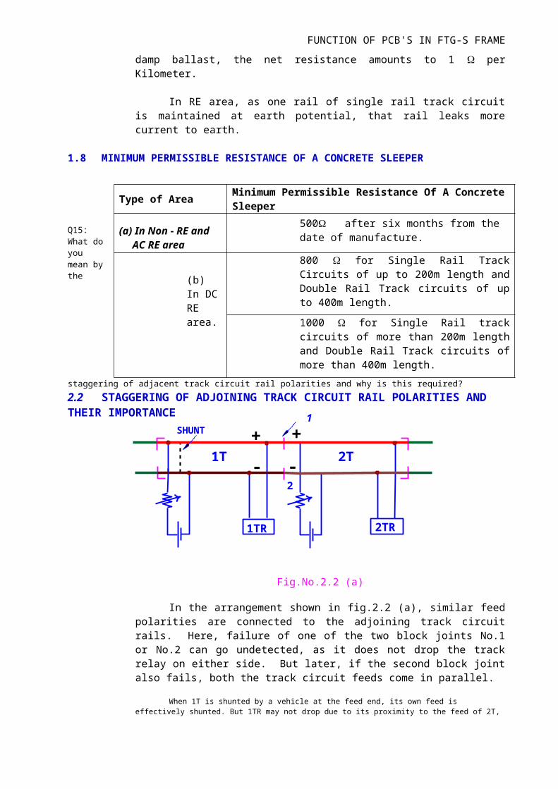
2.2 STAGGERING OF ADJOINING TRACK CIRCUIT RAIL POLARITIES ANDTHEIR IMPORTANCE
Fig.No.2.2 (a)
In the arrangement shown in fig.2.2 (a), similar feed polarities are connected to the adjoining track circuit rails. Here, failure of one of the two block joints No.1 or No.2 can go undetected, as it does not drop the track relay on either side. But later, if the second block joint also fails, both the track circuit feeds come in parallel.
When 1T is shunted by a vehicle at the feed end, its own feed is effectively shunted. But 1TR may not drop due to its proximity to the feed of 2T, while the shunt is remotely connected making it less effective. This is an unsafe condition, which should be avoided.
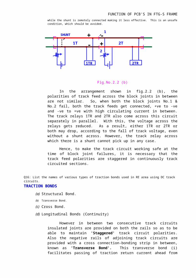
Fig.No.2.2 (b)
In the arrangement shown in fig.2.2 (b), the polarities of track feed across the block joints in between are not similar. So, when both the block joints No.1 & No.2 fail, both the track feeds get connected, +ve to -ve and -ve to +ve with high circulating current in between. The track relays 1TR and 2TR also come across this circuit
1
Type of Area Minimum Permissible Resistance Of A Concrete Sleeper
(a) In Non - RE and AC RE area
500 after six months from the date of manufacture.
(b) In DC RE area.
800 for Single Rail Track Circuits of up to 200m length and Double Rail Track circuits of up to 400m length.
1000 for Single Rail track circuits of more than 200m length and Double Rail Track circuits of more than 400m length.
FUNCTION OF PCB'S IN FTG-S FRAME
separately in parallel. With this, the voltage across the relays gets reduced. As a result, either 1TR or 2TR or both may drop, according to the fall of track voltage, even without a shunt across. However, the track relay across which there is a shunt cannot pick up in any case.
Hence, to make the track circuit working safe at the time of block joint failures, it is necessary that the track feed polarities are staggered in continuously track circuited sections.
Q16: List the names of various types of traction bonds used in RE area using DC trackcircuits.
TRACTION BONDS
(a) Structural Bond.
(b) Transverse Bond.
(c) Cross Bond.
(d) Longitudinal Bonds (Continuity)
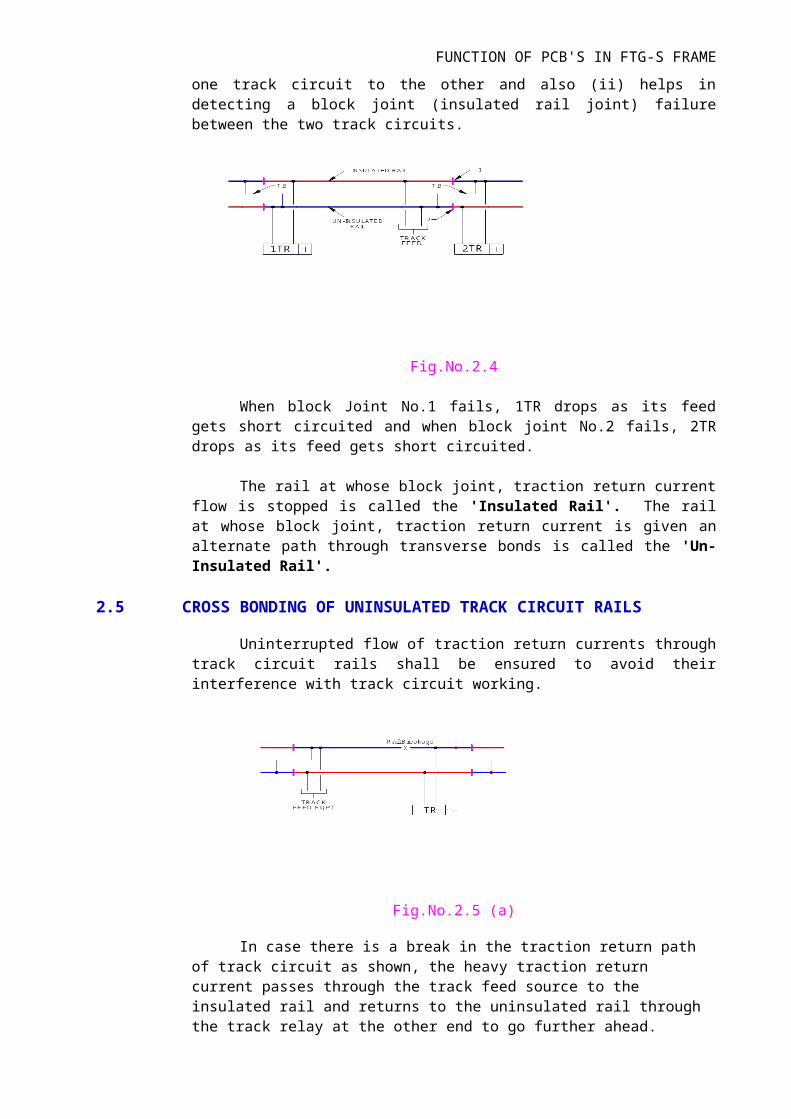
However in between two consecutive track circuits insulated joints are provided on both the rails so as to be able to maintain 'Staggered' track circuit polarities. Also the negative rails of adjoining track circuits are provided with a cross connection-bonding strip in between, known as 'Transverse Bond'. This transverse bond (i) facilitates passing of traction return current ahead from one track circuit to the other and also (ii) helps in detecting a block joint (insulated rail joint) failure between the two track circuits.
Fig.No.2.4
When block Joint No.1 fails, 1TR drops as its feed gets short circuited and when block joint No.2 fails, 2TR drops as its feed gets short circuited.
The rail at whose block joint, traction return current flow is stopped is called the 'Insulated Rail'. The rail at whose block joint, traction return current is given an alternate path through transverse bonds is called the 'Un-Insulated Rail'.
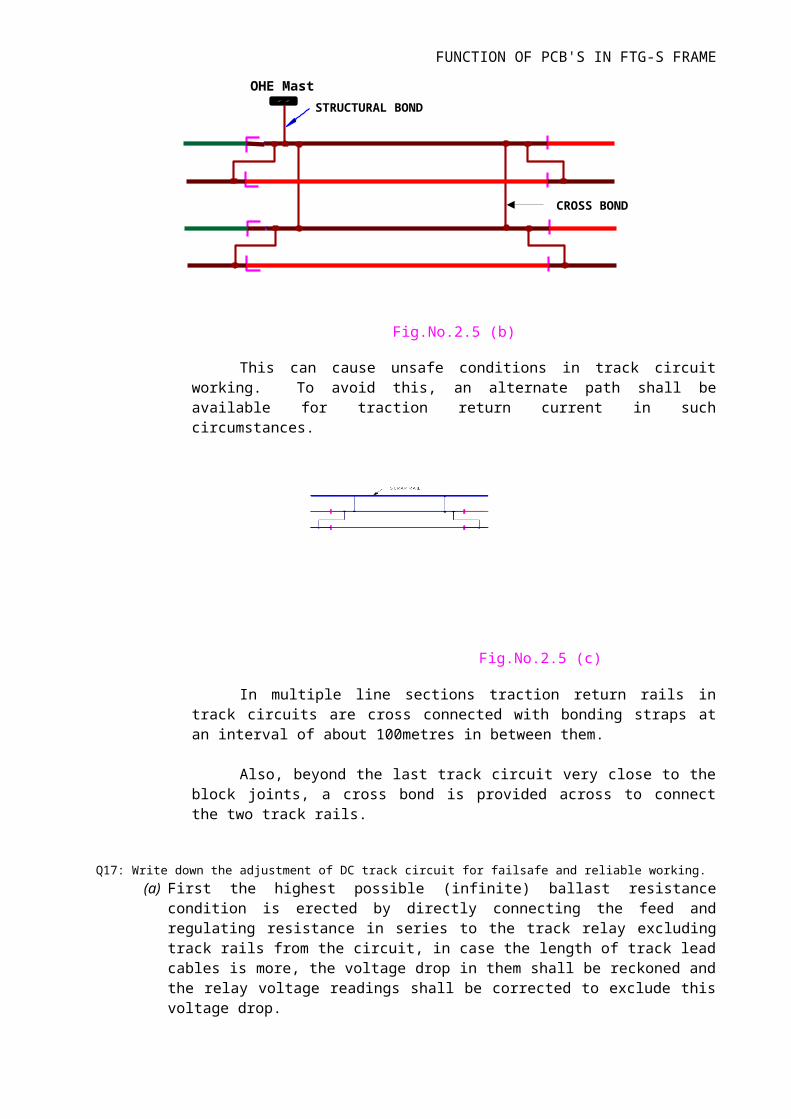
2.5 CROSS BONDING OF UNINSULATED TRACK CIRCUIT RAILS
Uninterrupted flow of traction return currents through track circuit rails shall be ensured to avoid their interference with track circuit working.
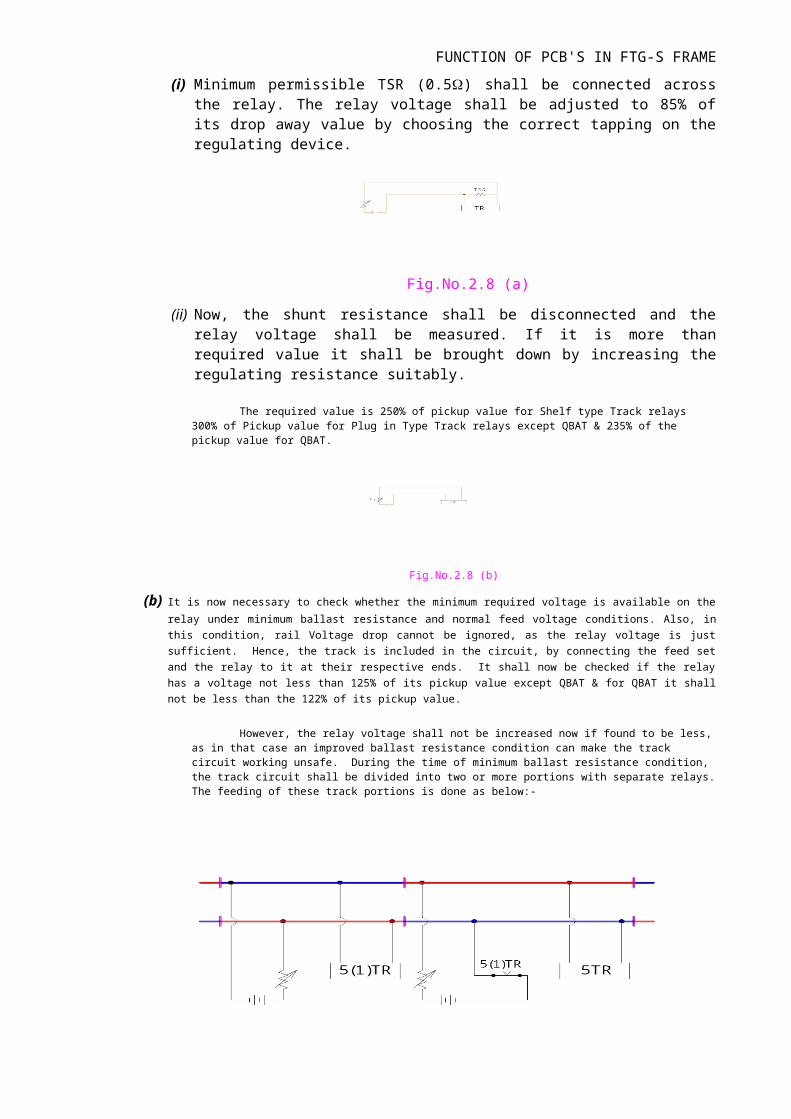
CROSS BOND
OHE Mast
STRUCTURAL BOND
FUNCTION OF PCB'S IN FTG-S FRAME
Fig.No.2.5 (a)
In case there is a break in the traction return path of track circuit as shown, the heavy traction return current passes through the track feed source to the insulated rail and returns to the uninsulated rail through the track relay at the other end to go further ahead.
Fig.No.2.5 (b)
This can cause unsafe conditions in track circuit working. To avoid this, an alternate path shall be available for traction return current in such circumstances.
Fig.No.2.5 (c)
In multiple line sections traction return rails in track circuits are cross connected with bonding straps at an interval of about 100metres in between them.
Also, beyond the last track circuit very close to the block joints, a cross bond is provided across to connect the two track rails.
Q17: Write down the adjustment of DC track circuit for failsafe and reliable working.
FUNCTION OF PCB'S IN FTG-S FRAME
(a) First the highest possible (infinite) ballast resistance condition is erected by directly connecting the feed and regulating resistance in series to the track relay excluding track rails from the circuit, in case the length of track lead cables is more, the voltage drop in them shall be reckoned and the relay voltage readings shall be corrected to exclude this voltage drop.
(i) Minimum permissible TSR (0.5) shall be connected across the relay. The relay voltage shall be adjusted to 85% of its drop away value by choosing the correct tapping on the regulating device.
Fig.No.2.8 (a)
(ii) Now, the shunt resistance shall be disconnected and the relay voltage shall be measured. If it is more than required value it shall be brought down by increasing the regulating resistance suitably.
The required value is 250% of pickup value for Shelf type Track relays 300% of Pickup value for Plug in Type Track relays except QBAT & 235% of the pickup value for QBAT.
Fig.No.2.8 (b)
(b) It is now necessary to check whether the minimum required voltage is available on the relay under minimum ballast resistance
and normal feed voltage conditions. Also, in this condition, rail Voltage drop cannot be ignored, as the relay voltage is just sufficient. Hence, the track is included in the circuit, by connecting the feed set and the relay to it at their respective ends. It shall now be checked if the relay has a voltage not less than 125% of its pickup value except QBAT & for QBAT it shall not be less than the 122% of its pickup value.
However, the relay voltage shall not be increased now if found to be less, as in that case an improved ballast resistance condition can make the track circuit working unsafe. During the time of minimum ballast resistance condition, the track circuit shall be divided into two or more portions with separate relays. The feeding of these track portions is done as below:-
FUNCTION OF PCB'S IN FTG-S FRAME
Fig.No.2.8 (c)
This arrangement is known as 'fed over' or 'cut section' track circuit arrangement. The relay connected to the last portion of the track is treated as the track relay of the entire. Section involved for the purpose of detection and other controls.
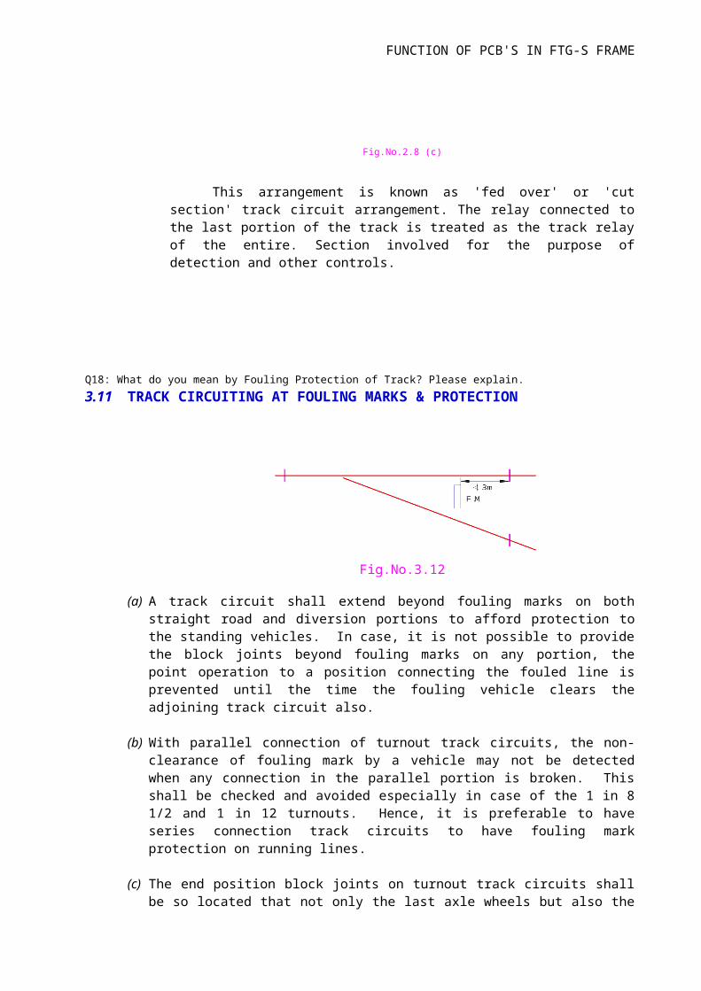
Q18: What do you mean by Fouling Protection of Track? Please explain.
3.11 TRACK CIRCUITING AT FOULING MARKS & PROTECTION
Fig.No.3.12
(a) A track circuit shall extend beyond fouling marks on both straight road and diversion portions to afford protection to the standing vehicles. In case, it is not possible to provide the block joints beyond fouling marks on any portion, the point operation to a position connecting the fouled line is prevented until the time the fouling vehicle clears the adjoining track circuit also.
(b) With parallel connection of turnout track circuits, the non-clearance of fouling mark by a vehicle may not be detected when any connection in the parallel portion is broken. This shall be checked and avoided especially in case of the 1 in 8 1/2 and 1 in 12 turnouts. Hence, it is preferable to have series connection track circuits to have fouling mark protection on running lines.
(c) The end position block joints on turnout track circuits shall be so located that not only the last axle wheels but also the overhanging portions of vehicle (1.8m) clear the fouling mark before the track relay picks up. So, in case of Crossovers, Block joints shall be provided from the Fouling mark at a distance of NOT LEES THAN 3m.
D.S
LEVELCROSSING
RLY TRACK
FUNCTION OF PCB'S IN FTG-S FRAME
Q19: What is Dead Section in track circuit area and how can it be eliminated?
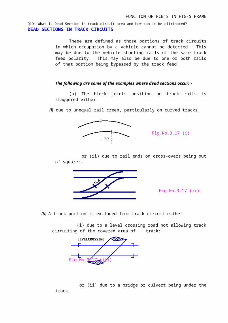
DEAD SECTIONS IN TRACK CIRCUITS
These are defined as those portions of track circuits in which occupation by a vehicle cannot be detected. This may be due to the vehicle shunting rails of the same track feed polarity. This may also be due to one or both rails of that portion being bypassed by the track feed.
The following are some of the examples where dead sections occur: -
(a) The block joints position on track rails is staggered either
(i) due to unequal rail creep, particularly on curved tracks.
Fig.No.3.17 (i)
or (ii) due to rail ends on cross-overs being out of square:-
Fig.No.3.17 (ii)
(b) A track portion is excluded from track circuit either
(i) due to a level crossing road not allowing track circuiting of the covered area of track:
Fig.No.3.17 (iii)
or (ii) due to a bridge or culvert being under the track.
or (iii) due to a tram line passing across the railway track.
Fi
6m in BG3.6 m in M.G/N.G MG/NG
1.8 min BG
11.7 m (39')
1.125m in MG/NG
FUNCTION OF PCB'S IN FTG-S FRAME
Fig.No.3.17 (v)
While allowing for dead sections in track circuits, the following precautions shall be taken so as to avoid unsafe conditions of traffic over them: -
The dead section shall not accommodate a four-wheeler vehicle entirely in itself without shunting any 'live' portion of the track circuit at the same time.
In B.G sections, the distance between the two axles of a four-wheeler is 6m (20') and in MG /NG sections, it is 3.6m (12').
Fig.No.3.17 (vi)
If one trolley of an eight-wheeler gets entirely accommodated in a dead section, the second trolley of the same vehicle shall not go beyond the live portion of that track circuit in either direction.
In B.G sections, the distance between the two axles of this trolley is 1.8m (6') and in MG/NG sections, it is 1.125m (3'9").
In this case, the track circuit shall extend on either side of dead section by more than 12m (40').
Fig.No.3.17 (vii)
If the dead section is longer than 10.8m(36') as in the case of long bridges underneath the track, a 'Trap Circuit' shall be provided including the control of dead section track by two other track circuits on either side as shown.
Q20: What do you mean by cut section track circuit and/or fed over track circuits?
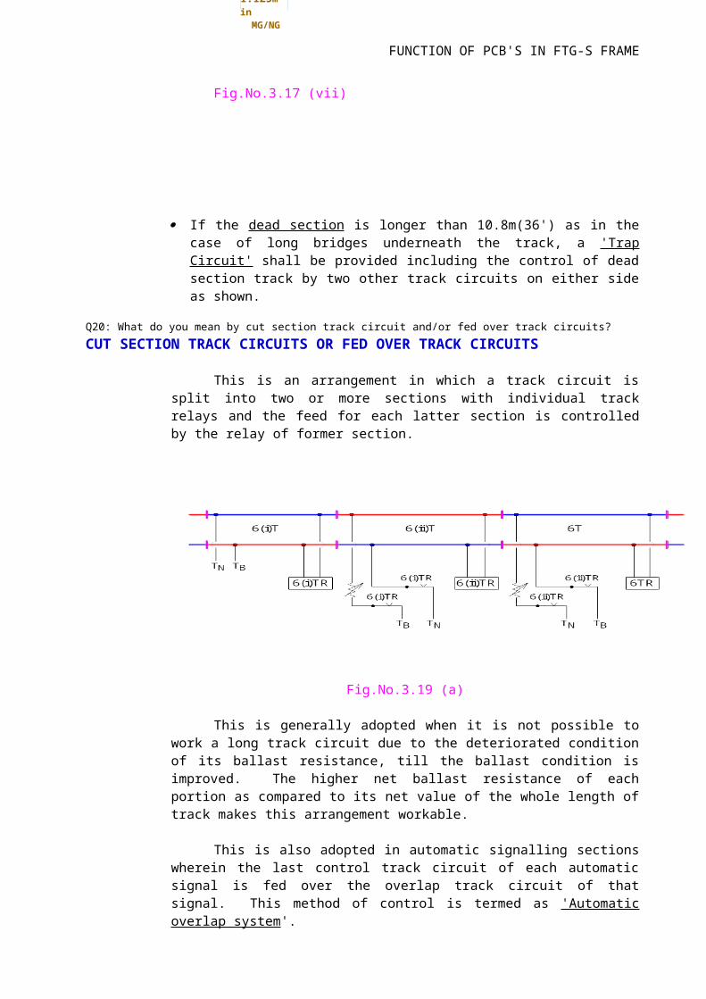
CUT SECTION TRACK CIRCUITS OR FED OVER TRACK CIRCUITS
This is an arrangement in which a track circuit is split into two or more sections with individual track relays and the feed for each latter section is controlled by the relay of former section.
S101 S103 S105
A1T 101T 101AT 103T 103AT 103BT 105T
FUNCTION OF PCB'S IN FTG-S FRAME
Fig.No.3.19 (a)
This is generally adopted when it is not possible to work a long track circuit due to the deteriorated condition of its ballast resistance, till the ballast condition is improved. The higher net ballast resistance of each portion as compared to its net value of the whole length of track makes this arrangement workable.
This is also adopted in automatic signalling sections wherein the last control track circuit of each automatic signal is fed over the overlap track circuit of that signal. This method of control is termed as 'Automatic overlap system'.
Fig.No.3.19 (b)
In this arrangement, when 101 ATR goes down, 103TR which also controls S103 is still picked up but when 103TR goes down, 101ATR cannot pickup until 103T is also cleared by the running train. Thus while 101AT controls only S101, 103T controls both S101 and S103.
Q21: Can an AFTC be used in a track section with steel sleepers? Why?
Q22: What do you mean by "End Fed" and "Centre Fed" types of AFTCs along-withcorresponding maximum permissible lengths of track circuits?
Three modes of connections are adopted for FTGS-depend on the length of section and location
(a) STANDARD LAYOUT
FUNCTION OF PCB'S IN FTG-S FRAME
(b) CENTRE FED LAYOUT
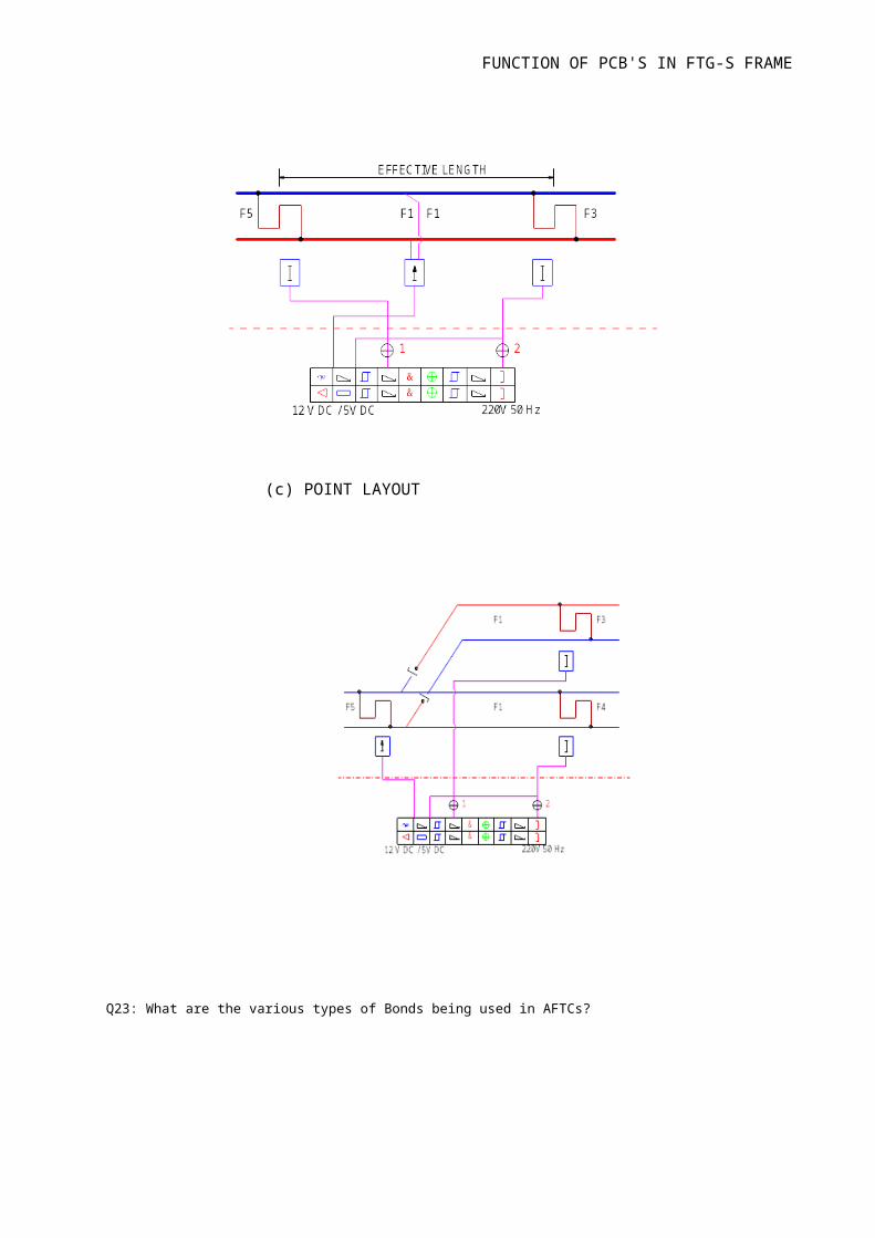
(c) POINT LAYOUT
FUNCTION OF PCB'S IN FTG-S FRAME
Q23: What are the various types of Bonds being used in AFTCs?
FUNCTION OF PCB'S IN FTG-S FRAME
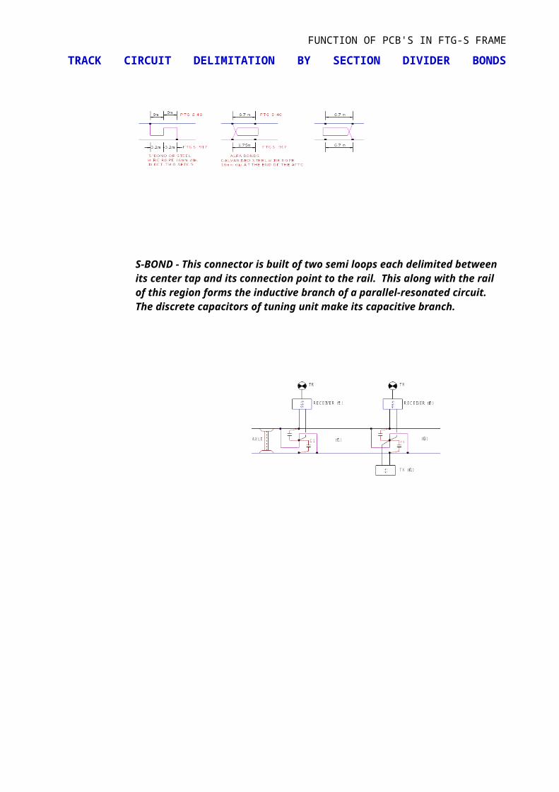
TRACK CIRCUIT DELIMITATION BY SECTION DIVIDER BONDS
S-BOND - This connector is built of two semi loops each delimited between its center tap and its connection point to the rail. This along with the rail of this region forms the inductive branch of a parallel-resonated circuit. The discrete capacitors of tuning unit make its capacitive branch.
FUNCTION OF PCB'S IN FTG-S FRAME
The more distant semi loop of the two S-bonds delimiting a track section is tuned to the operating frequency of track circuit. Feed is applied to the resonated semi loop circuit causing its transmitter to consume little energy. The other semi loop of section divider is tuned to the operating frequency of neighboring track circuit. Due to the layout of semi loops in the S-bond, an axle standing on the S-bond occupies both the near and advance track circuits. This S-bond causes overlapping, of the two track circuits so that there is no detection gap.
In the last AFTC of a region, End bonds (Alfa bonds) are provided at their exact delimitation or for their transition to other types of track circuits with block joints in betweenQ24: Please list the names of the constituent parts of a Electrical Lever Lock and itsfunctioning.
LEVER LOCKS AND CIRCUIT CONTROLLERS.
1 INTRODUCTION: In mechanical installations the functions are operated by a lever through a
mechanical rigid means i.e. for points by rod transmissions and for signals by wire
transmission. In Electro-mechanical installations the functions are operated by mechanical
lever without any rigid connection. Because of this the function may go out of
correspondence with the lever. To avoid this condition over the mechanical lever different
electrical locking are required to provide. This will be done by means of “Electrical lever lock”
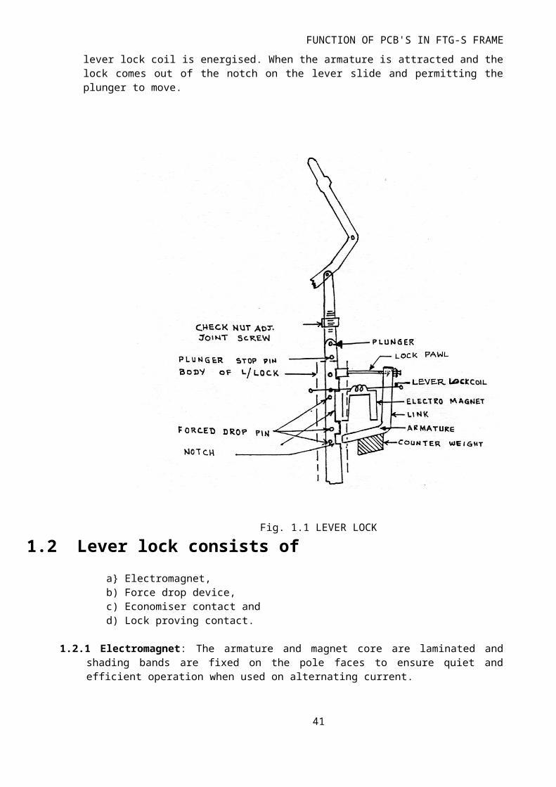
1.1 Electric Lever Lock: Electric lever lock is used where an electrical control on a mechanical lever is required. Levers controlling points and signals are equipped with electric locks to prevent or limit their movements. The lock pawl holds the lever mechanically so that the lever cannot be operated when the condition for its operation is not safe. In figure 1.1 shown the armature extension (lock pawl) engages in the notch cut on the lever plunger (slide) in order to lock the lever when the electro-magnet is de-energised. Consequently, the lever cannot be operated till the lever lock coil is energised. When the armature is attracted and the lock comes out of the notch on the lever slide and permitting the plunger to move.
30
FUNCTION OF PCB'S IN FTG-S FRAME
Fig. 1.1 LEVER LOCK
1.2 Lever lock consists of
a Electromagnet,b) Force drop device,c) Economiser contact and d) Lock proving contact.
1.2.1 Electromagnet: The armature and magnet core are laminated and shading bands are fixed on the pole faces to ensure quiet and efficient operation when used on alternating current.
1.2.2 Force drop device: Some times the armature of the lever lock may not release after de-energisation of lock coil due to residual magnetism or any other mechanical holding which may lead to unsafe conditions by allowing the lock to release without proving the required safety condition. To ensure that the lock pawl is positively pushed inside the locking notch before every unlocking operation, a mechanical arrangement called “Force drop” is provided. The force drop pins/nibs are riveted on the slide and a bevel shaped extension is provided on the lock pawl. The force drop pins/nibs force the lock pawl to drop into the locking notch through its bevel shaped extension before each pick up.
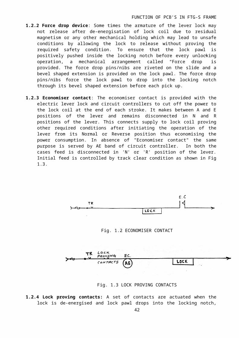
1.2.3 Economiser contact: The economiser contact is provided with the electric lever lock and circuit controllers to cut off the power to the lock coil at the end of each stroke. It makes between A and E positions of the lever and remains disconnected in N and R positions of the lever. This connects supply to lock coil proving other required conditions after initiating
31
FUNCTION OF PCB'S IN FTG-S FRAME
the operation of the lever from its Normal or Reverse position thus economising the power consumption. In absence of "Economiser contact" the same purpose is served by AE band of circuit controller. In both the cases feed is disconnected in 'N' or 'R' position of the lever. Initial feed is controlled by track clear condition as shown in Fig 1.3.
Fig. 1.2 ECONOMISER CONTACT
Fig. 1.3 LOCK PROVING CONTACTS
1.2.4 Lock proving contacts: A set of contacts are actuated when the lock is de-energised and lock pawl drops into the locking notch, proving that the lever is locked positively. An electrical circuit taken through these proving contact, proves that the armature is de-energised and consequently the lever is locked. Fig 1.3
1.3 Indication locking circuit: It is a locking provided on B AND D position of point lever slide and in the case of signals on B position only.
Fig.1.4A INDICATION CIRCUIT
1.4 Track locking circuit: Held in lever lock is released when the lever is either in A or B position with track clear condition. Locking of the point levers provides a safeguard against the derailment during hand signalled movement. Since track locking and indication locking are provided on the point lever, combined track locking and indication locking is used as shown in fig. 1.5
32

FUNCTION OF PCB'S IN FTG-S FRAME
Fig.1.4B TRACK LOCKING CIRCUIT
Fig. 1.5 COMBINED CKT OF TRACK AND INDICATION LOCKING
1.5 Circuit Controllers: Circuit Controller is a device by which electrical circuits can be made or broken according to requirements. It has generally got the two sets of fixed contacts and corresponding numbers of rotating contacts. The rotating contacts may be of different positions such as N,R., NB, RD, etc. The contact segments are rotated by a plunger connected to the lever. Each rotating segment can be adjusted in steps of few degree (3 ¾ deg in SGE circuit controller) and locked in position. Though the lever lock and circuit controllers may be used separately, they can also be combined together on a lever lock and circuit controller.
A sketch showing the relative positions of circuit controller contacts to that of the lever controlling them are shown in Fig.1.6 for converting the linear motion of the plunger to the circular motion of the contact segments, different methods such as cam path, rack and toothed sector, crank motion etc., are used by different manufacturers.
33
FUNCTION OF PCB'S IN FTG-S FRAME
N = Full normal position of lever.A = Normal Economiser Position.B = Normal Indication Position.C = Centre positionD = Reverse Indication position.R = Full Reverse Position.
34
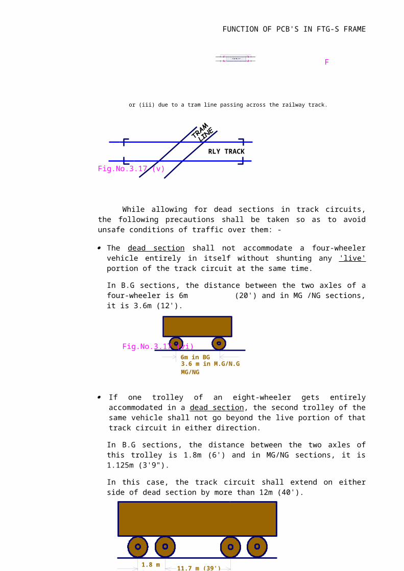
Fig. 1.6 CIRCUIT CONTROLLERS
Q25:: What do you mean by Indication Locking and Track Locking and on which leversthese are being used?
Q26: Explain the working of Snubbing Circuit in Point machine operation using 3-wirecontrol.
Snubbing Circuits: At the completion of point throw and locking, the cut off contacts ensure that the supply to the point motor is cut off, but the momentum of the motor will keep it running. The presence of the clutch between the point motor and the throw rods which are connected in the switch rails ensures that undue strain on the motor will not take place. In addition to this, to provide a smoother stopping, an electrical circuit may be provided, by which the kinetic energy of the motor is dissipated and the point motor is brought to a smoother stop. It is mostly employed in high speed machines. Some of the snubbing circuits employed are discussed below
Snubbing circuits are completed through a) snubbing relay contact,b) directional contact and c) a half wave rectifier.
4.12.1 Snubbing relay contact : In point machine a snubbing relay is used. The snubbing relay remains energised throughout the operation of point machine and at the end of the operation when the feed to the point motor is cut off, the snubbing relay drops. Through the back contact of this relay and the reverse or normal snubbing contact (RS-makes in reverse position) armature and the field winding are short circuited. When one field widning is used for working the motor, the other field winding is used for snubbing. When the armature and field are short circuited, the induced current develops an opposite torque which causes motor to stop smoothly. Refer Fig.No.4.11.
Fig No : 4.11.SNUBBING BY USING RELAY CONTACT
35 | P a g e
Q27: What is the concept of Cross protection in signalling circuits? Please explain.
Q28: Explain the working of 4-wire point detection circuit using circuit diagram.Four wire detection: (Refer Fig.4. 19).
In this detection, 4 wires are used between the relays and the nearest detector. Since two neutral relays are used, there is a possibility of both relays picking up at the same time. To prevent this the back contact of RWKR is used in NWKR circuit and the back contact of NWKR is used in RWKR circuit. To ensure correspondence between the lever and the function, the concerned lever contacts also can be used.
In the above-mentioned point indication circuits cross protection arrangements are not provided. During the operation of the point neither the normal detection contacts nor the reverse detection contacts are available and hence the relay is de-energised. In this position, to prevent the relay being energised by a cross feed, an arrangement is provided by which the indication relay is shunted by a detector contact which makes only during the operation of points.
Q29: What do you mean by super imposed detection of points? As per the latestdirectives of Railway Board, is it suggested to use this arrangement?
Super Imposed Detection: Normally, separate sets of wires are used for point control and point indication circuits. I.e For point operation 3 conductors and point indication circuits 4 conductors are used i.e total 7 conductors are required for point operation and point detection . To effect economy on line wires and give greater protection against the external feeds, the idle point control and the return wires are used for indication and when such an arrangement is known as "super-imposed detection". Normally point control supply is DC and indication supply is AC. The indication circuit voltage is kept low, so that the motor operation cannot take place while the indication is being given. In this arrangement only 4 conductors are used for both point operation and detection circuits.
36 | P a g e
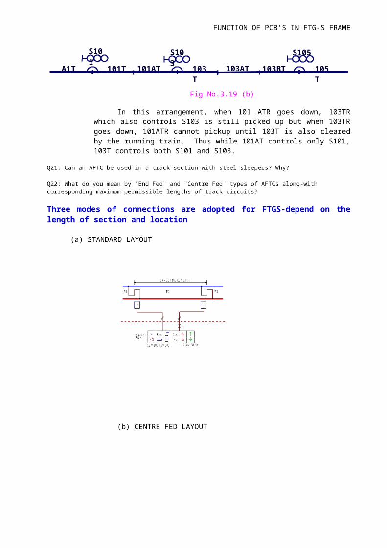
Fig No : 4.20 SUPER IMPOSED CIRCUIT
Q30: Write down the general features of IRS Rotary Type point machines with 143 mm stroke.
Q31: Explain the working of Point operation circuit using Siemens Point Contactor unit in an electromechanical installation.
Q32: What do you mean by RHS and LHS turnouts? Can we use the same type of Pointmachine (IRS Rotary type) for both the turnouts? Please explain.
Q33: Compare different types of conventional signal lamps.
Q34:: What are the different types of ECRs being used with conventional signal lamps?
Q35: What are Triple Pole lamps? Describe their merits over Double pole lamps.
Q36: What do you mean by H-Type, I-Type and L-Type signal transformers along-withtheir uses?
Q37: What is Aspect Control and Aspect Control circuits? Draw an aspect control circuit for an inner distant signal in Double Distant signalling territory.
Q38: What is cascading of signal aspects? Explain with suitable circuit diagram.
Q39: What do you mean by Red Lamp Protection? Expalin with suitable diagrams.
Q40: What do you mean by Cutting in Arrangement in signalling circuits and reason for its use?
Q41: What do you mean by "Direct Feeding", "Local Feeding" and "Remote Feeding" of signals? Explain.
37 | P a g e
Q42: Describe the advantages of LED signal Lamps over conventional signal lamps.
Q43: What are the various PVC signal cables used in Railway signalling in SECR? Arethey screened one or not?
Q44: What do you mean by cable meggering? Please explain.
Q45: What is Electric Signal Reverser? List different types of Electric Signal Reversersbeing used over Indian Railways.
Q46: What do you mean by EKT? Describe the working of EKT.
Q47: What do you mean by TS, TSS, FP, SP & SSP? Please explain.
Q48: What are the effects of RE in signalling?
Q49: List the names of various types of Block Instruments being used in stations onSingle/Double line and RE/Non-RE area. What special feature is incorporated in theblock instruments meant for use in RE area?
Q50: What do you mean by maximum length of parallelism in Railway Signalling overRE area? Explain.
Q51: Why the repeater relays of track Relays are made Slow To Pick-up and with whattime delay and why? Explain.
Q52: What are the reasons behind using various traction bonds in Track Circuits overRE area?
Q53: What arrangements/changes are required to be carried out in the DC track circuits being used in RE area w.r.t. Non-RE area?
Q54: What are the effects of RE in signalling circuits and how are they minimised?
Q55: List the various types of Route indicators used in Railway Signalling and whichtype is being commonly used in Indian Railways?
Q56: What are the items which are being used to increase the length of a DC trackcircuit in RE area? What are the maximum permissible length of track circuits in Singleand Double line section on RE area?
Q57: What are the maximum permissible distances for direct feeding of signals onSingle and Double line section in RE area?
38 | P a g e
Q58: What are the various means of suppressing the value of induced voltages at thesource of 25 kV traction? Explain.
Q59: Draw a sketch showing the arrangement of power supply, neutral section feeding post, sectioning & sub sectioning posts.
Q60: Draw and explain the State Transition diagram for the working of Axle Counter.
Q61: What are the different constituent parts of an axle counter?
Q62: What is Trolley Suppression Track circuit? Why is it necessary in Axle counter?
Q63: What are approach locking, back locking and dead approach locking in electricalsignalling? Explain with suitable examples using sketches.
Q64: What do you mean by Sectional route release in electrical signalling? Explain with suitable example using sketches.
Q65: What is Crank Handle Interlocking in Railway signalling? Explain with suitableexample using sketch.
Q66: What is LC Gate Interlocking in Railway signalling? Explain with suitable examples using sketches.
Q67: What is the working principle of 24V battery charger used in Railway signalling?Explain with sketch.
Q68: What do you mean by Filters in electrical rectifier circuits? What is the differencebetween the chargers being used in signalling and telecommunication applications?
Q69: What is IPS? Describe in detail. How many battery banks are used in IPS inRailway signalling?
Q70: What is electrical transformer? Explain its working in detail.
Q71: Mention the major advantages of the SMPS over Thyristor controlled Powersupplies.
Q72: What is an Inverter and where is this being used in Railway Signalling?
Q73: Calculate the total load in a typical 4 line way side station with one siding line and a common loop in a Double line section. Draw necessary sketches.
Q74: In a PI installation, which circuit ensures the "One Signal-One Train" feature?Please mentioned the name of this circuit and explain with suitable example.
39 | P a g e
Q75: Explain the signal control circuit for a home signal with one route with suitablesketch and circuits.
Q76: List the name of activities pertaining to signal department which require priorsanction of CRS for their execution in the yards.
Q77: What is the validity period of CRS sanction? Explain the process for obtainingCRS's sanction.
Q78: What do you mean by ground connections?Q79: What is the role of Drawing Office in S&T department?
Q80 What are the equipments to be provided with a Trolley/Lorry/Motor Trolley?
Q81 What is IB signal? Why this signal is provided? Is it being provided on single linesection? Explain the working of an IB signal.
Q82 What is the procedure to pass an IBS signal at its ON aspect by the driver of anytrain?
Q83: What is half notch? Why is this provided and in which equipment/instrument?
Q84 Draw the Block Clearance circuit for SGE Double line instrument using appropriatecircuits.
Q85 What are the principles of Lock and Block working? How these are achieved inSGE Double Line Block Instrument?
Q86 In Siemens signal group relays, the GLSR relay is made slow to release. Why?Please explain.
Q87 What are the items to be checked during scrutiny of Engineering Scale Plan?
Q88 What items will you check during inspection of a motor operated point?
Q89 What items will you check during inspection of SSDAC?
Q90 What item are being noted during day/night footplate?
Q91 What items are being noted during joint point and crossing inspection with SE/SSE (P-Way)?
Q92 Draw the ALSR CKT for signal number S- ?
Q93 How will you councell your staff to prevent short cut method?
40 | P a g e
Q94 Why Disconnection Memo should be issued before attending to maintenance ofcertain signal gears & for which activities/works, it should it be issued?
Q95 (a) What is the propose of using the choke in single rail DC track circuits in REarea?
Q95 (b) What is half notch? Why is this provided and in which equipment/instrument?
Q96 Draw the complete diagram of Single Rail DC track circuit in RE area includingvalue of cack component?
Q97 What parameters are being checked during inspection of Analog Axle Counter andwhat are their standard values?
Q98 (a) What are the conditions for granting line clear in double line B class station onMACLS territory?
Q98 (b) What are the conditions for granting line clear in single line B class station onTwo Aspect CLS territory?
99. Draw the dog chart of following: - 2X3W5R
100. For the given yard draw the RCC for the following signals: - Down Home Signal (S-1), Shunt Signal (Sh- 26), Starter Signal (S-4) and CallingOn signal (Co-2).
FOR SELECTION FROM JE/I/Tele to SE/Tele MW
1. What is Radio Patch? Describe it with the help of a Suitable diagram to patch control circuit, in case of need. 2. Explain phase lock loop system with suitable diagram. 3. How rainfall attenuation is measured in MW communication. 4. What are the advantages of digital MW communication in comparison with the analog MW? 5. Write one method of finding the modulation index. 6. Discuss different methods for avoiding the fading in MW communication. 7. Discuss the salient features of DTL-MUX equipment. 8. Draw a block diagram of Transreceiver radio equipment of Digital radio MW. 9. What is the testing carried out before taking over the charge of digital MW system? 10. Draw the block diagram for Radio Equipment? 7D6 & 7D15 11. Explain the function of 7D6 & 7D15 Radio Equipment? 12. What is fading? What are the counter measures Railways adopt to present? 13. What is DTL MUX? Explain it with diagram? 14. What is the meaning of video in & video-out signal-in Radio equipment? 15. How many types of measuring instrument are used in MW circuit? Write short notes on each? 16. Write the short notes to explain the following? · Channel Modem Card. · VFT card.
41 | P a g e
· Design & set up the MW Communication in between two MW station and two telephone exchanges in Railways?
CONTROL
1. Draw a neat sketch of a six pin socket wiring practiced in RE area and indicates the advantage in it. 2. Explain in detail DTMF Signaling and its advantages? 3. Why two tones are transmitted at a time in DTMF signaling? What are it's advantages? 4. What are the types of traffic train control being used in Railways? Explain each of them? 5. What is total interruption of control? What is the work procedure at stations in such situations?
RE & 6 Quad CABLE
1. What is meant by Loading in RE Cable? 2. What is meant by BON? Why and where it is used in RE Cable? 3. What is meant by Half Loading Section? 4. What is meant by Screening Factor in an underground telecommunications cable? 5. Write down types of Telecom Cable used in Railway for different communication system. 6. Discuss benefits of replacement of O/H alignment by 6Q cable. 7. Write jointing procedure of 50 pair PIJF cable.
EXCHANGE
1. What is meant by Pulse Code modulation? 2. Give the working principle of Digital Exchange & its features. 3. Describe the properties of earthing used in Telecom with specific values used for resistances, wire diameter, in each case. 4. Explain the working of SPC Exchange in brief with block diagram. 5. Describe PCM-TDM with appropriate diagram where it is used. 6. What are the functions of Line cards? 7. Explain Call processing in Electronic Exchange. 8. Write different types of tones with frequency and `ON' and `OFF' time duration for each case. 9. What is "hunt group"? Explain the requirement of hunt groups. 10. What is DID and DOD. Explain advantages of these. 11. Write down the maintenance & protection of electronics exchange? How it is better than strongers? 12. Advantage of Digital Exchange over analog Exchange? 13. Write 10 of features of electronic exchange. Which you would like to have in your exchange? 14. Draw the basic structure of ISDN Exchange? What are the advantages & procedure's of it's working. 15. Explain the structure of 2mbps bit stream with frame & multiframe? 16. Explain Bit-interleaving and Byte-interleaving? 17. Write down procedure to augmentation of electronic exchange up to 5000 Lines along with justification. Prepare the brief estimate also. 18. How we can add two exchanges with 2MB connectivity? What will be its advantages. 19. Discuss and explain difference between IP exchange and SPC exchange. 20. Discussed feature of ISDN with block diagram?
OFC
1. Explain the function of an OLTE in Optic-Fiber-System? 2. What are the advantages of Optic fiber cable over the conventional cable system? 3. How STM is more useful in SDH system over PDH system.
42 | P a g e
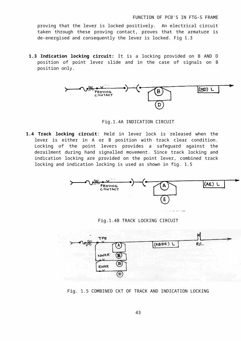
4. How monomode fiber is advantageous for communication network rather than multichrome. 5. How dispersion is reduced in graded index fiber. 6. Discuss the merits & demerits of SDH? 7. What may be the reasons of alarm in OFC communication system? 8. Discuss the difference between PDH & SDH system? Also advantages of SDH over PDH system. 9. Explain different network Topologies & basic, requirement of topologies? 10. Write down in what ways transmission & reception occurs in OFC. How OFC can be optimum utilized in Indian Railways. How we can expand uses of OFC in Commercial ways. 11. What are test conducted in OFC? 12. How we can patch from OFC to conventional cable? 13. What is RDSO specification of OFC Cable. 14. Detail the works of Railtel? How this body is advantageous for Railways.
RAILNET
1. What is LAN? What is the difference between internet & intranet, and which can be categorized under LAN? 2. What do you meaning of LAN, WAN, MAN & VLAN? 3. What is the function of Router? 4. How networking in our Railway has been done? Discuss its benefits & procedures for Internet Connectivity. 5. Discuss different network topologies? Give explanation diagram for each? 6. How to connect 10 nodes (PC) in network. Explain with diagrams, detailing equipments needed. 7. Explain different network Topologies. Also explain requirement of individual topologies with diagrams? 8. What is Router? What types of ports are available in Router? 9. Explain the functions of switch? Also detail the advantages of switch over HUB? 10. What is VPN? How it will be useful in a corporate network? 11. What is Layer 3 switch? 12. What is synchronous & asynchronous communication? 13. What is the use of NMS to monitor and control the problems in Railnet? 14. Detail the differences between OSI & ISO layer? 15. Differentiate between L-3 switch and Router? 16. Difference between Hub and switch with diagrams? 17. What do you mean by NMS? 18. What is the permissible length between switch to switch via CAT-5/6 cable? 19. What is TCP/IP and UDP? 20. Why OFC cable is used in LAN? What are it's advantages? 21. Give details of AFRES, MMIS, and PRIME? 22. Why VLAN used? What are the advantages of VLAN configuration over the normal configuration? 23. Give full form of SNMP. Detail its basics and why it is used? 24. What is the meaning of MAC ? 25. What is IP address? Also give details of four sections of it. 26. Explain OSI seven layer model? 27. What is synchronous and asynchronous communication? 28. What type of mail server is being used in our Railway? 29. What are the minimum number of ports in a Router? 30. What theory used in LAN, is it Multicast, Unicast or Broadcast? 31. What is RAS and what are it's functions?? 32. What is proxy server? Why Proxy server is being used in SEC Railway? 33. What do you mean by MPLS? Where it is used? 34. For testing one Hop distance which command are used? 35. How many types of modem are used for network? Specify for permanent & dialup types? 36. What do you mean about Firewall?
43 | P a g e
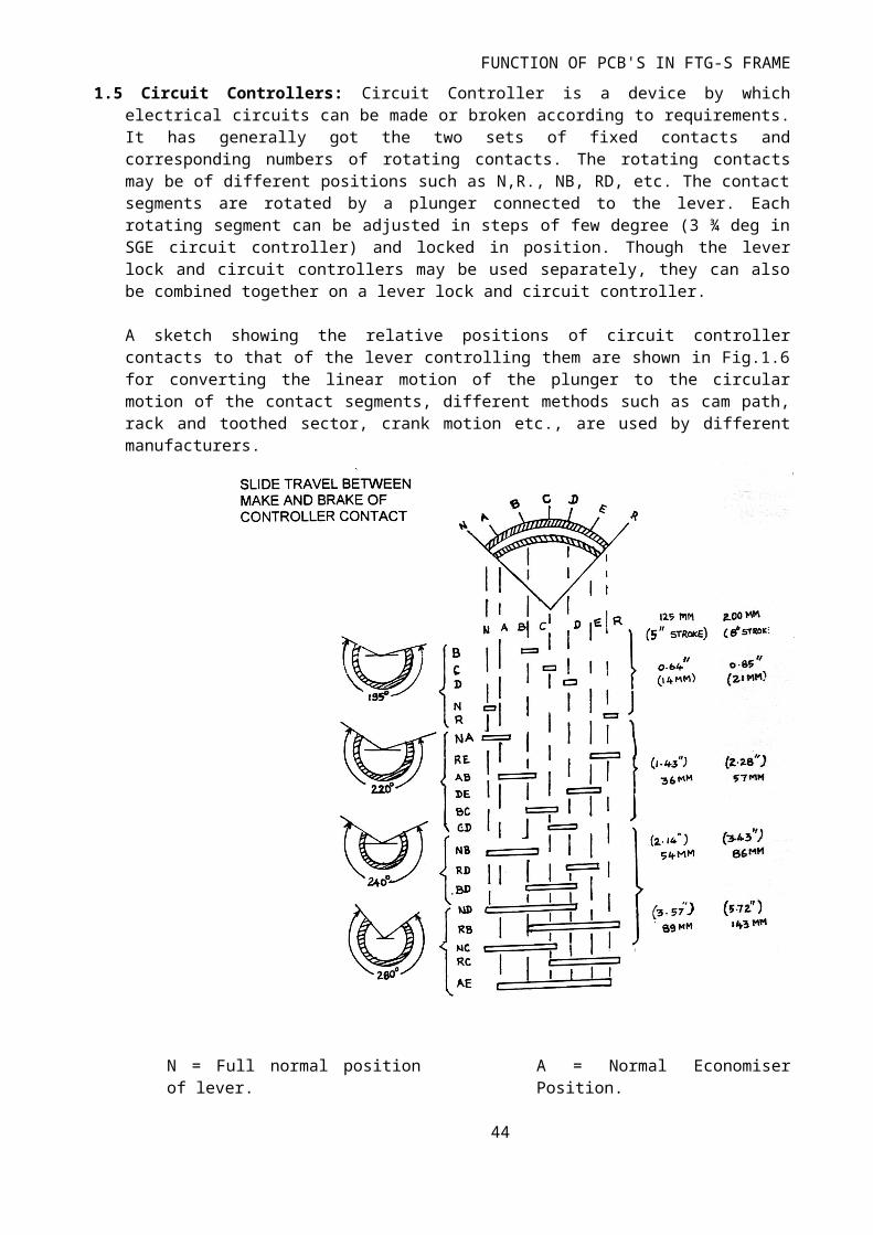
37. Why NetBIOS protocols are used? 38. In Railway which type of architecture are used for MIS? 39. List the differences between ROM & RAM? 40. What Operating and application software are used in client and server side in Railways for MIS application? 41. What do you mean by UTP CAT5/6 cables? 42. What is Hop distance? 43. For route checking which command are used in command mode? 44. What do you mean about IDS, IPS in security? 45. Which technology used for wireless data communication between two PCs. or Mobile to PC? 46. Bandwidth for STM-1 & E-2 steam? 47. MAC address is which Layer address in OSI Layer? 48. What are the terms indicated by subnet mask ? 49. Give an example of IP address, subnet mask and gateway of router with simple example? 50. Draw a block diagram of SECR Railnet with all network devices and servers and explain each network devices in brief. (Including R & NGP) 51. Give short notes on: · VOIP · URL · NIC · CSMA/CD · Frame · Packet
FOIS
1. How do we connect FOIS network between two stations. Explain with block diagram. 2. What are the advantages we are getting from FOIS? Explain fourth point of public & Railways. 3. Explain with block diagram the connectivity of FOIS between Divisions to HQ in SECR.
PASSENGER AMENETIES
1. Discuss how Touch & Feel system works in Railway. What are items included in it? 2. Discuss unification of PRS & UTS. What are the advantages of it? 3. Discuss how IVRS, video conferencing, Call Centre, Train Charting/Voice Recorder works. 4. Draw a block diagram of PRS at a way side station? 5. Write down the working principle of Coach Guidance System and Train indication board?
Interaction with other public agencies
Give short notes on:(i) SACFA(ii) PTCC(iii) WPC
Write short notes: -
a. Wave Guide b. Space Diversity c. Fade Margins d. Frequency Diversity e. Railnet f. FOIS g. OTDR
44 | P a g e

h. NTES i. IVRS j. DTMF Signaling k. ISDN l. LAN m. WAN n. FOIS o. MODEM p. LAN Extender q. Router r. Voice Data Logger s. NMS t. PRC u. CCB Telephone v. Q signaling w. Jitter & Wander x. PDH y. SDH z. Leased line aa. BRI bb. PRI cc. TDM dd. PCM ee. CUG scheme Objective type questions (i) Write full forms of the following i. CEPT card ii. ISDN iii. SMPS iv. MTBF v. OTDR vi. SCADA vii. ACSR viii. OLTE ix. MODEM x. NMS xi. UTS xii. PIJP xiii. DTMF xiv. BON xv. GSM xvi. CRIS xvii. FOIS xviii. SPC xix. DTMS xx. COIS xxi. AMI xxii. HDB-3 xxiii. TDM xxiv. RMS xxv. STM xxvi. LAN xxvii. WAN xxviii. PCM xxix. GRIM xxx. CUG xxxi. TDM xxxii. NMS
(ii) Write True/False of the following:-
45 | P a g e
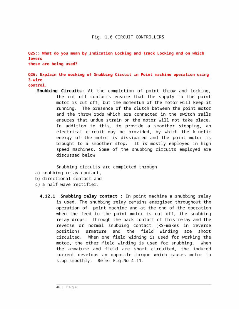
1. In OFC Cable Repeater, Index of Core is kept higher than clad. (For Total Internal Reflection) (T/F) 2. OTDR can be used to measure the Splice loss also in OFC-(T/F) 3. Inmarset works via satellite and any access to Private Network is not required- (T/F) 4. In (PRS+UTS) unified system UTS counter can issue a Reserved Ticket- (T/F). 5. For Radio Patching working of CNL cuts. It is necessary to convert 4W.CKT into 2W before patching.- (T/F). 6. With MLLN of CNL cuts, it is necessary to convert 4W CKT into 2W before patching- (T/F). 7. In DTMF dialing always two different frequencies are transmitted (T/F). 8. 1 Watt is equal to 30 dbm. (T/F) 9. 672 MB are provided in STM-I (T/F) 10. OTDR is used in Digital MW. (T/F). 11. WAN can be provided in closed premises. (T/F). 12. In TDM, the transmission of signal is on time sharing basis. (T/F) 13. In SPC Exchange, the switching network set up temporary connection between two are more exchanges. (T/F) 14. LAN Extender can be used for WAN connectivity (T/F). 15. Specification of OFC Cable is IRSTC-55(T/F).
(iii) Fill in the blanks.
1. The duration of a multiframe is ...........2. In a 30 channel system, the sampling time period is.............3. In 30 cahnnel PCM system, a time slot duration is ............. microsecond.4. STM 4 is having -----------2Mb5. In data circuit, Data transfer limit in CAT-6 cable is ---------6. Channel transmission capacity of STM-1 is --------------7. Bit rate of 2Mb with --------------------- PPM tolerance.8. Bit rate of 2nd order mux ----------------- Kbps ---------------- PPM tolerance.9. Duration of frame -------------------10. Duration of Time slot -------------------11. What does EPABX stand for ----------------------------------12. Analog Subscriber loop resistance ------------------------ Ohm.13. Working voltage of electronic exchange ----------------- V ----------------- tolerance.14. Ideal working Temperature of exchange ---------------------15. Dial tone ------------------ Hz modulated with ----------------- Hz frequency.16. Ring back tone ------------------ Hz modulated with ------------------ Hz frequency.17. Busy tone ------------------- Hz modulated with --------------- Hz frequency.18. Switch is a ------------------ device (Broadcasting/Unicasting).19. Switch function on the principle of ------------------ (CSMA/CDMA).20. Insertion loss of Telephone equipment in the case of: -· Handset is on the -----/switch/Nil · Handset is off the -----/switch/0.2db· Press to -------"button pressed/3.0db
QUESTION BANK FOR THE SELECTION OF JE-I(SIGNAL) TO SE(SIGNAL) (Objective/True-False and short Questions)
1 Operating Current of coil of indicator in DLBI is about:- i) 40 50 mA ii) 95-100mA iii) 17-25 mA iv) 37-42 mA
2 Rated current and coil resistance of a polarized relay is:- i) 100 mA & 100 Ohm ii) 33 mA & 25 Ohm iii) 25 mA & 77 Ohm iv) 125 mA & 77 Ohm
3 L-Type of transformers are used:-
46 | P a g e
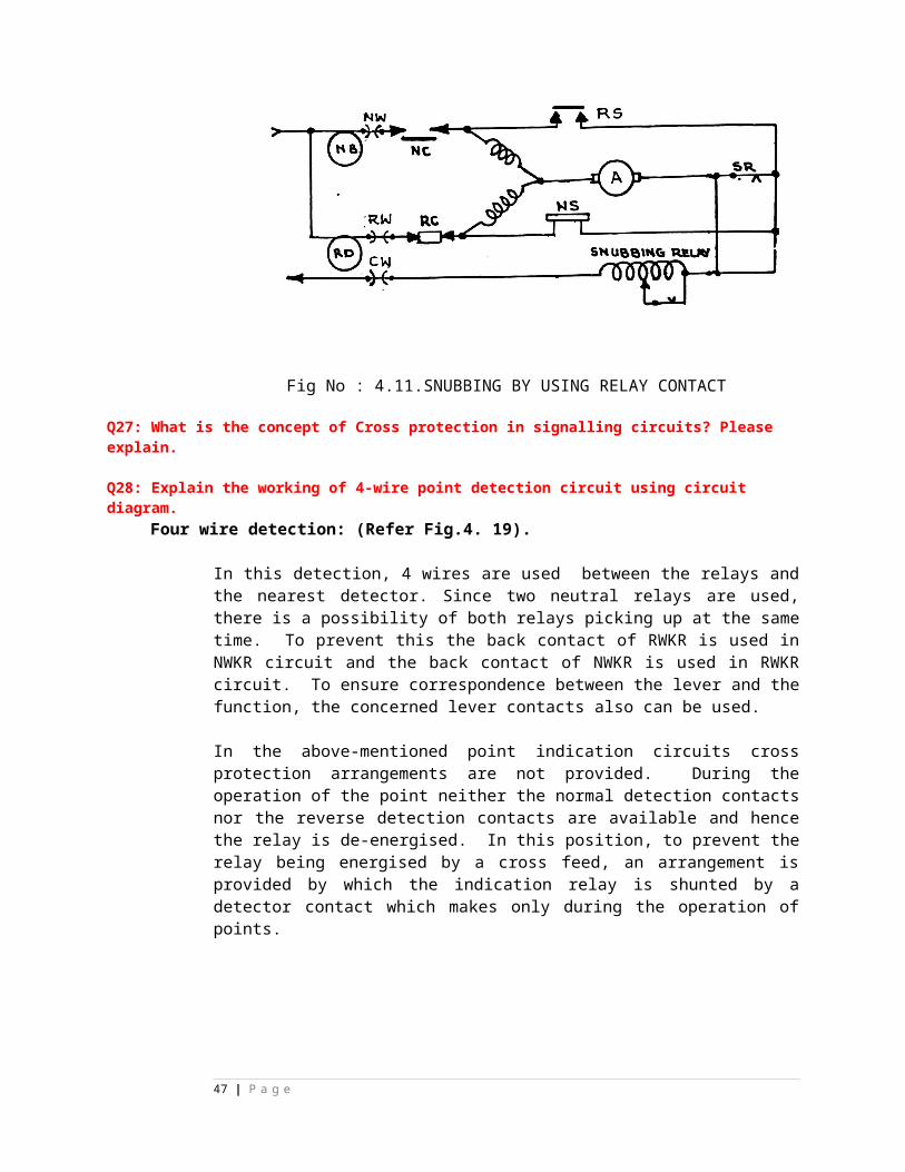
i) Where Signals lamps are directly fed up to 605 Mtr. ii) Where LED Signals lamps are used. iii) Where Signals lamps are directly fed up to 240 Mtr iv) Where Signals lamps are directly fed beyond 1000 Mtr
4 Rating of SL-35B triple pole lamps is :- i) 12 V/24W,24W ii) 12V/24W,18W iii) 24 V/24W,24W iv) 24V/12W,12W
5 The No. of front and back contacts in QTA2 relay is:- i) 1F/1B ii) 2F/1B iii) 1F/2B iv) 2F/2B
6 Minimum permissible TSR with concrete sleeper track circuits in RE area is:- i) 2.5/KM ii) 0.6 /KM iii) 0.25/KM iv) 0.5 /K
7 QS3 DC neutral Relays are used in :- i) All circuits of non RE section ii) Only internal circuits of RE area iii) In axle counter in place of self type relay iv) Point machine controlling RE area
8 QJ1 DC neutral Relays are used in :- i) All circuits of non RE section ii) For timing control iii) In axle counter in place of self type relay iv) Point machine controlling RE area
9 Lamp proving relays are :-
i) Current sensing DC line relays ii) Voltage sensing DC line relays iii) Current sensing DC track relays iv) Voltage sensing DC track relays
10 Rated Voltage and Power of an AC LED signal is :- i) 230V, 15W ii) 110V, 50W iii) 110 V, 15W iv) 230V, 50W
11 In DLBI Commutator handle gets locked when it is turned :- i) From Line Close to Line Clear ii) From Line Clear to Line Closed iii) From Line Closed to train on Line iv) Line Clear to Train on Line
12 ALSR Relay is used for :- i) Sequential route release ii) Sectional Route release iii) Route Locking iv) Dead approach locking
13 EUYNR is: - i) Emergency route cancellation relay ii) Emergency group signal cancellation Relay iii) Emergency route cancellation button relay iv) 120 second time delay relay
14 Commissioner of Railway Safety (CRS) belongs to theministry of:-
47 | P a g e
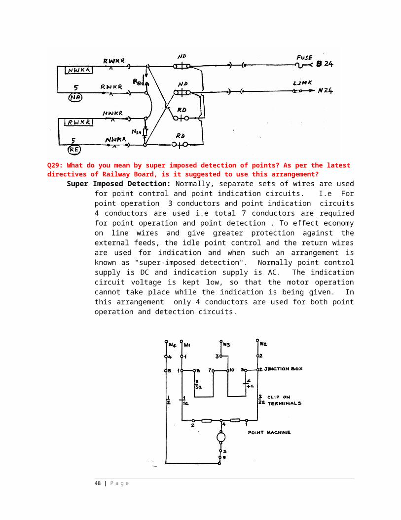
i) Railways ii) Civil Aviation iii) Surface Transportation iv) Labour
15 Refresher course of signal supervisors is required once in:- i) 3 Year s ii) 5 Years iii) 4 Years iv) 6 Years
16 Number of aspects in the Inner Distant signal of an IBS signal in Double Distant signalling territory is:- i) 3 ii) 2 iii) 4 iv) Same as those of its Distant Signal
17 Longitudinal bonding is provided by: i) Engineering Department ii) Electrical department iii) S&T department iv) Combined with ii &iii
18 Induced voltage in unscreened cable for double line is i) 116 V/Km ii) 95 V/Km iii) 87.5 V/Km. iv) 78.5V/Km19 Maximum length of direct feeding for screened and unscreened cables respectively is i) 890 m and 980 m ii) 345m and 543m iii) 600m and 240m iv) 640m and 200m
20 IRS type high thrust point machine can operate safely with maximum contact test load of.....kg on the throw bar i) 670 ii) 700 iii) 730 iv) 760
21 Stroke of IRS type point machine is i) 143 mm ii) 220 mm iii) Both i and ii iv) Stroke can be adjusted between 110 mm to 220 mm
22 No. of throw rod, detection rod and lock rod in IRS type point machine are i) 1, 2 and 2 ii) 2,1 and 2 iii) 2, 2 and 1 iv) 2,2 and 2
23 Study the following statement about testing of Glued Joints A) In dry condition resistance of glued joint shall be less than 25 Mega ohm when meggering voltage of 100 V DC is applied across the joint B) In wet condition resistance of glued joint shall not be less than3 Kilo ohm when meggering voltage of 100 V DC is applied across the joint.
Which of these statements are true? i) Both A & B ii) Only A
48 | P a g e
iii) Only B iv) None of A & B
24 Study the following statement A) For track Circuits lengths up to 700 m, Maximum permissible rail resistance is 2 Ohm/Km B) For track Circuits lengths more 700 m, Maximum permissible rail resistance is 0.5 Ohm/Km. Which of these statements are true
i) Both A & B ii) Only A iii) Only B iv) None of A & B
25 Study the following A) Rail resistance = (Voltage Drop in Rails)/ Average track circuit current B) Ballast Resistance = (Average rail Voltage)/Leakage Current
Which of these statements are correct?
i) Both A & B ii) Only A iii) Only B iv) None of A & B
26 Study the following statement A) For safe working of track Circuits, without a shunt across the track, track relay excitation shall not exceed 250% of its pick up valve. B) With normal feed source voltage and minimum permissible ballast resistance of the track, Track relay voltage shall be less than 125 % of its pick up valve. Which of these statements are true? i) Both A & B ii) Only A Only B iii) iv) None of A & B
27 Study the following statement A) In DLBI block bell has separate line wire. B) In DLBI Top indicator needle of station in advance is connected to bottom indicator needle of station sending train. Both A & B are correct i) ii) Only A is correct iii) Only B is correct iv) None of A & B are incorrect
28 Study the following statement A) In DLBI, Commutator handle should locked first before the "Train on line" indication appears on the indication when the handle is turned from "Line Clear" to "Train on line" position. B) If turning of Commutator is done quickly, a situation may arise when TOL contacts are made but the Commutator is not locked in TOL position. i) Both A & B are correct and B is correct explanation of A. ii) Both A & B are correct and B is not correct explanation of A iii) Only A is correct.
49 | P a g e

iv) Only B is correct.
29 Study the following statement A) A transverse Rail Bond is provided connecting all the non- insulated rails. B) This provides continuous return path to traction current.
i) Both A & B are correct and B is correct explanation of A. ii) Both A & B are correct and B is not correct explanation of A iii) Only A is correct. iv) Only B is correct.
30 Study the following statement Transverse Bond is provided by ......... department and identification of non-insulated rail is done by..........department. i) S&T, Electrical ii) S&T, S&T iii) Electrical, S&T iv) Electrical, Electrical
31 Study the following statement A) In double cutting arrangement, proving of control contacts is done on either limb of HR coil. B) This prevents false energisation of HR from multiple faults. i) Both A & B are correct and B is correct explanation of A. ii) Both A & B are correct and B is not correct explanation of A iii) Only A is correct.
50 | P a g e
iv) Only B is correct.
32 EI & PI are provided for stations having no. of routes..... and ...... respectively. 0-25, 25-200 i) ii) 70-100, 20-35 iii) 50-200, 0-50 5-100, 100-200 iv) 33 Track crossings of signalling cables are done at a depth of 1meter below .......... Ballast Level i) Top Level of Rail ii) Bottom Level of Sleeper iii) Bottom Level of Rail iv)
34. M/s CEL is one of the manufacturers for: a. Analog Axle Counters only b. Integrated Power Supply c. Electronic Interlocking Equipment d. Both Analog and Digital Axle Counters
35. For Mechanical Signal Items, who does the inspection of materials? a. RDSO b. RITES c. Consignee d. None of the above.
36. The "Outlying Siding" is referred to the siding for which: a. The siding line takes off from running lines and the siding is located out side of that station. b. The siding line takes off from running lines and is located in side of that station. c. The siding line takes off from running lines and located between block stations. d. An additional line is provided for this purpose in any station.
37. CRS's sanction is not required for the following work in the existing yard? a. Replacing mechanical operation of a point with motor operation b. Inserting a turnout on passenger running line c. Shifting of a signal from LHS to RHS. d. Opening of a new line for public
38. The following is wrong with respect to track repeater relay (TPR)? a. It has 12 Front /4 Back contacts b. It is of QNA1 type c. It has got AC immunity against induced voltages d. It is an example of track relay
39. The power supply Track Circuits are taken through which
51 | P a g e
of the following components/modules of the IPS? a. Rectifier b. DC-DC converter c. Inverter d. Transformer40. Choose the correct option for Digital Axle Counters presently being used in SEC Railway a. It has both "Preparatory" and "Hard" Resetting options b. It doesn't require trolley suppression track circuit c. It can detect more than one section d. It uses only Two conductors for establishing communication between the pair of EJBs
41. Block Bell Equipment is used for a. Converting AC line voltage coming from the Block instrument at other end of station to required DC voltage in local Block instrument b. Converting high AC line voltage coming from the Block instrument at other end of station to a required low AC voltage in local Block instrument
c. Converting high DC line voltage coming from the Block instrument at other end of station to a required low DC voltage in local Block instrument d. Converting DC line voltage coming from the Block instrument at other end of station to required AC voltage in local Block instrument
42. What is the approximate maximum distance for Direct Feeding of conventional signal lamps on Double Line RE area? a. 180 meters b. 600 meters c. 595 meters d. 220 meters43. Choose the correct answer from the following a. The term "Block Forward" is concerned with the station lying only in a Single Line section b. The term "Block Back" is concerned with the station lying only in a Single Line section c. The term "Block Back" is concerned with the station lying either in a Single Line section or a Double Line section d. The term "Block Back" is concerned with the station lying only in a Double Line section
44. The signal overlap for IBS signal is a. 120 meters b. 180 meters c. 200 meters d. 400 meters
45. The Outer and Warner signals in LQ signalling territory are examples of a. A permissive and stop signals respectively b. A stop and permissive signals respectively c. A subsidiary and main signals respectively d. Both are subsidiary signals
46. What is the normal aspect of main signals in Automatic Signalling territory?
52 | P a g e

a. Yellow b. Red c. Green d. Double Yellow47. As per the latest policy of Railway Board, Level Crossing Gate can be interlocked if the TVU of the LC gate is a. Up to 20,000 b. Below 25,000 c. Between 15,000 to 20,000 d. More than 25,000
48. Which is correct with respect to VCOR in signalling installations? a. This is a special type of relay used in Digital Axle Counter b. This is a special type of relay used to control rectifier output of an IPS c. This is a special type of relay used in Electronic Interlocking d. This is a special type of relay used in Siemens RRI
49. The working of an electrical transformer is based on a. Mutual Inductance b. Self Inductance c. Hall Effect d. Self Conductance
50 Circuit wiring in PI installations over SECR is being done with a. 0.6 mm tinned wire b. 1.0 mm tinned wire c. 16/0.2 multi strand copper wire d. 1.5 Sq. mm copper wire
51 Fill in the blanks:-
i) For Roding, running under the track the minimum distance between top of Roding and bottom of rail should be.... ii) Minimum length of the lock bar for a broad gauge is........ iii) Lock bar should have minimum no. of Clips....... iv) The colour of point lever is ........ v) Resumption of normal working after overhauling can be done by SSE / Signal if no. of lever are not more than ........ vi) All gates within station limit are called ...gates. vii) A gate qualifies for interlocking if the TVU are more than........ viii) Clearance between road surface and LC boom should be between ......to...... Meter. ix) Far boom locking to be effective it shall not be possible to lift the boom by .....From close position. x) Minimum of. ........ % of spare conductors are to be provided in the main cable up to farthest point zone. xi) Station section in a "C' class station is from ......to ......... xii) Specification of self regulatory battery charger is S......... xiii) A concrete sleeper is used in track circuited area if it has a minimum resistance of ....Ohms between insert to insert. xiv) Minimum cross section of lead wire for track circuit should be .......mm. xv) Excitation level of a track relay will not be less than .......of rated pick up voltage. xvi) Plug in type of track relays has to replace after .......years. xvii) The overhauling period of DLBI is ..........years.xviii) For obstruction test of a point test piece is kept at a .........
53 | P a g e
distance from the tow ofxix) Fuse of correct capacity should be of about ......time the rated current in signaling circuit.xx) The minimum implantation distance of a colour light signal from the centre of the track should be ...........xxi) The colour of shunt signal button on the panel is ...........xxii) Route setting on the panel is indicated by.......xxiii) UYR relay is used for ..........xxiv) WCR relay is used for.............xxv) ALSR is used for ..........xxvi) The value of induced voltage in unscreened cable in double line section is ........ohm/Km.xxvii) The AC immunity of a IRS point machine is.......Ohm.xxviii) As per SEM the minimum visibility of a distance signal in MACLS territory is........xxix) The Block Section Limit Board is located at minimum .....metre from home signal.xxx) Clamp type direct locks are desirable for speed above......... Km/Hour.
52. Write full form of :-
(i) SPAD(ii) CCRS(iii) RAMS(iv) ECTS(v) CTC(vi) SSDAC(vii) MSDAC(viii) EKT(ix) REB(x) TLJB(xi) MACLS(xii) OLWR(xiii) DMTR(xiv) MTTR(xv) MTBF
53. Write true or false:-
i) Insulated rail shall be kept clear of the ballast by 25mm.ii) Only single rail track circuit can be provided in 25 KV Ac area.iii) Rail joint bonds are maintained by S&T department.iv) Audio frequency track circuit does not require glued joints.v) Diodo token less block instrument cannot be used in RE area.vi) 3-Phase point machine is immune to induced voltage and can be used to any length of parallelism.vii) Direct feeding of AC LED signals is permitted up to 2 Kms.viii) All external circuit requires cross protection arrangement.ix) When SM key is out no operation can be done from the panel.x) Calling- on signal button is of red colour with white dot.xi) Implantation distance is painted in red colour on signal post if distance is more than 2.36 metre.xii) Shelf type line relays are overhauled on after every 15 year.xiii) CRS approval is required for locating a signal on right side.xiv) For solid rodding the minimum unsupported length is 1.8 metres.xv) Green notice is issued by traffic department.xvi) The type of turn out is specified in Interlocking plan.xvii) Calling- on signal detects all the points in routes and overlap.xviii) After two months of commissioniong responsibility of
54 | P a g e
maintaining Signalling gears in station lies on open line even if station is not handed over to open line.xix) Interlocking of a L. C. gates requires sanction of CRS.xx) QSPA1 relay is used as repeater of TR.xxi) Authority to proceed means authority to enter in block section.xxii) Station limit and station section means same thing.xxiii) Class "D" stations are non interlocked.xxiv) Double yellow aspect means caution.xxv) A depended shunt signal has no ON aspect.xxvi) In automatic signaling letter "A" in white on black circular disc is provided.xxvii) Absolute block system is most prevalent system of block working.xxviii) Driver can pass an Automatic signal in red without any authority.xxix) Caution board is provided at 400 metre away from speed indicator board.xxx) Grease/petroleum jelly can be provided on secondary battery terminals to prevent corrosion.xxxi) The LED ECR used in ON aspect can also be used for route aspect.xxxii) SL-21 signal lamps have two filaments of equal rating.xxxiii) The maximum length of track circuit in RE area using PSC sleeper is 350 metres.xxxiv) Force drop arrangement is provided in EKT.xxxv) Calling on signal is of lunar white colour.
Syllabus basic concept -S1
State true OR false
S.NO
Question Write answer
Key
1 Indications for caution aspect is proceed and be prepared to pass next stop signal at restricted speed.
( ) False
55 | P a g e
2 OFF aspect of a Warner signal is attention. ( ) False
3 Normal aspect of distant signal in double distance territory is caution.
( ) False
4 Normal aspect of automatic stop signal is proceed. ( ) True
5 Name of aspect and indication of UQMA signal and MACL signal are not same.
( ) False
6 UQ distant signal cannot combine with a stop signal. ( ) False
7 Combining of signal shall be done under approved special instruction.
( ) False
8 Simultaneous reception and despatch shall be done under special instructions.
( ) False
9 Function of passenger and goods warning board is same. ( ) True
10 A Warner signal and a distant signal perform same function.
( ) False
11 Shunting can be performed in face of approaching train at class “A” station.
( ) False
12 The block overlap and signal overlap in two aspect signaling and multi-aspect signaling is 180 Mts.
( ) True
13 A Warner signal(semaphore) is permissive signal and provided with a “P” marker.
( ) False
14 Passenger warning board shall be placed at distance of 1KMts in rear of first stop signal in a station with multi-aspect colour light signaling.
( ) False
15 The block overlap in multi aspect signaling is more than L.Q. signal.
( ) False
16 When distant signal display green aspect then it indicates run though condition.
( ) False
17 Shunt signal can be placed below first stop signal. ( ) False
18 Calling On signal can be placed on last stop signal. ( ) False
19 The signal overlap in two aspect signaling is 120 Mts. ( ) False
20 Goods warning board shall be placed at distance of 1.4 KMts in rear of first stop signal.
( ) True
21 Warner signal at OFF indicate run through condition on Loop Line.
( ) False
22 On single line station signal overlap is reckoned form outer most point of station.
( ) True
56 | P a g e
23 Location of shunting limit board & Last stop signal is same.
( ) True
24 Isolation is not required in standard III interlocking. ( ) False
25 Block section limit board shall be provided at class B station on double line where first point is a trailing point OR no point with lower quadrant signalling.
( ) False
26 Visibility of Warner signal shall be 1.2 KMts for speed more than 100 KMPH.
( ) False
27 Lock detection is not required in revised standard II interlocking.
( ) False
28 If LC Gate is interlocked with advance starter then a G maker shall be provided below advance starter.
( ) False
29 Visibility of a pre-warned signal 200 Mt. ( ) True
30 Shunting limit board shall be placed at a distance of signal overlap from outer most point on double line.
( ) False
31 Block overlap class C station is 400 Mts always. ( ) True
32 Catch siding protect block section and slip siding protect station section.
( ) False
33 If speed is more than 50 kmph then one goods line need not be isolated from other goods line.
( ) False
34 Purpose of repeating and co-acting signal is same. ( ) False
35 More than one calling ON signal can be placed below a stop signal.
( ) False
36 A “P” maker shall be provided below UQ distant signal. ( )
37 First stop signal on signal line normally shall be placed at distance of signal overlap plus block overlap from outer most point.
( ) True
38 A “C ” marker shall be provided below a Semaphore miniature calling ON signal.
( ) False
39 Starter repeater and repeating signal are same signals. ( ) False
40 Simultaneous reception of trains is allowed under approved special instruction.
( ) False
41 If speed is less than 50 KMPH, then isolation of a passenger line from other connecting passenger line is not required.
( ) True
42 Under special instruction means approval from commissioner of railway safety.
( ) False
57 | P a g e
Fill up the blanks with correct answers
1 The block overlaps and signal overlap in Multi aspect signal are _____________ & ____________ respectively.
a) 180 Mt b) 400 Mt c) 120 Mt d) 300 Mt
( )
2 Semiautomatic signal is provided with
a) ‘A’ marker b) illuminated ‘A’ marker c) ‘AG’ marker d) ‘P’ marker
( ) b
3 A shunt signal can be placed
a) On post by it self b) below any stop signalc) Below any stop signal other than first stop signal d) a &c
( ) d
4 Shunting in the face of approaching train can be performed at --------------- station/stations
a) Class ‘A’ b) Class ‘B’ c) Class ‘c’ d) all a,b &c
( ) b
5 Attention aspect (double yellow) indicates that----------------
a) Two next signal ahead at OFF b) one next signal ahead at OFF c) Be prepared to pass next signal with restricted speed. d) a &c
( ) c
6 If distant signal in single distant territory display proceed aspect then it indicates-----------
a) Run through on main line b) Run through on loop line
c) Train is going to be received on Main line , d) all a,b &c
( ) c
7 Adequate distance in automatic block system on double line is ---------------------
a) 180 Mt b) 400 Mt c) 120 Mt d) 300 Mt
( ) c
8 Isolation is required for station with -------------------of interlocking
a) Standard I b) standard II c) standard III d) b&c
( ) d
9 Normal aspect of automatic signal is -----------------------
a) ON b) OFF c) proceed d) caution
( ) c
58 | P a g e
10 The possible maximum numbers of aspect in LQ signal with combination of signal is/ are ---------
a) Stop b) proceed with caution c) proceed d) all a,b,&c
( ) d
11 A catch siding shall be provided if the gradient stepper than 1:80 in near vicinity of station and falling --------------
a) Away from station b) Towards station c) Towards block section d) all a,b &c
( ) b
12 A slip siding shall be provided if the gradient stepper than 1:100 in near vicinity of station and falling --------------
a) Away from station b) to words station
c) To words block section d) all a,b &c
( ) a
14 If a semiautomatic stop signal is protecting LC gate as well as point then ----------- shall be provided on the post.
a) ‘A’ marker b) illuminated ‘A’ marker c) ‘AG’ marker d) b&c
( ) d
15 When the shunt signal and calling on signal is provided below stop signal then sequenced from top is ---------------------------------- signal.
a) First calling on then shunt b) first shunt and then calling on c) Not possible d) any of a, &b
( ) a
16 Aspects in distant signal in double distant signal territory is/ are
a) Attention b) a &c c) proceed d) caution
( ) b
17 The passenger warning board shall be provided 1 Km in rear of ------------ signal.
a) Home b) first stop c) routed home d) nun of above
( ) b
18 The section Gate under absolute block system shall be provided with ------- marker.
a) ‘G’ b) ‘AG’ c) ‘PG’ d) ‘A’
( ) a
19 If two automatic block section and overlap ahead of an automatic signal is clear of train then it will display
( ) a
59 | P a g e
--------------- aspect
a) Attention b) a OR d c) stop d) caution
20 The block overlap in class ‘C’ station provided with colour light signal is---------
a) 180Mt b) 400Mt c) 120Mt d) 580Mts
( )
21 Repeating signal is provided when ----------------
a) Signal is not continuous visible b) signal is not visible at all c) Prescribed visibility of signal is not available d) duplicate signal is to be provided.
( )
22 If speed is less than 15 KMPH then ------------- type route indicator shall be provided.
a) Directional b) stencil c) multi lamp d) any one of three
( )
Match the Following :
1. Signal overlap in LQ Signal (e ) a) 400Mt2. Block overlap plus signal overlap in LQ Signal (d ) b) 300Mt3. Signal overlap in automatic Signal (DL) (c ) c) 120Mt4. Block overlap plus signal overlap in UQ Signal (b ) d) 580Mt5. Block overlap in class ‘C’ station (a ) e) 180Mt
Match the Following :
1. Sighting distance (e ) a) station limit2. Block section limit board (d ) b) LQ signal station3. Shunting limit board (c ) c) Class B station single line4. Passenger warning board (b ) d) class B station MACLS double line5. Distant signal (a ) e) goods warning board
Match the Following :
1. Illuminated ‘A’ marker (e ) a) No ‘P’ marker2. ‘G’ marker (d ) b) P marker 3. ‘AG’ marker (c ) c) LC Gate and point4. Distant signal (b ) d) LC Gate in block section5. Distant cum gate home signal (a ) e) LC Gate in automatic section
S 2. State true/false
s.n Question Write Key
60 | P a g e
o answer
1 Swinger/top piece can not be used in the first & last
channels
( ) T
2 Reverse swinger can not be used in the second
channel
( ) T
3 Normal swinger can not be used in the last but one
channel
( ) T
4 Swinger shall not be used in the adjacent channel on
the same tappet
( ) T
5 Fouling of notches can not be over looked ( ) T
6 The total nos.of bridle bars at any given place of a
channel 2 top bridle bar +2 bottom bridle bar in catch
handle lever frame.
( ) T
7 If the distance from the signal & 1st facing point or from one facing point to next facing point is more than 180 Mts. then one holding bar to be provided.
( ) T
8 If the distance from the signal & 1st facing point or from one facing point to next facing point is more than 180 mtr then lock retaining bar to be provided
( ) T
9 Dummy Lock need to be provided if an unconnected length of a bridle bar exceeds more than 10 levers.
( ) T
10 Use of top pieces shall be a last alternative for avoiding fouling notches
( ) T
11 Warner is not released by any one of the Home Signal
( ) T
12 Signaling plan is prepared based on Type of Signaling, the class of Station
( ) T
13 Size of Catch handle type lever frame will be in
combination or multiples of 8 and 10
( ) T
14 “Direct” type lever frame size will be in combination or
multiple of 5 and 7
( ) T
15 Outer is released by any one of the Home Signal ( ) T
16 Width of the tappet is 41 mm in direct lever frame ( ) T
17 Width of the channel 40 mm in catch handle lever
frame
( ) T
18 Clearence between the two tappets is 59 mm in Catch ( )
61 | P a g e
handle lever frame
19 The lock dog should be riveted with the only one bridle
bar
( )
20 Length of swinger is 79 mm ( )
21 In SWCH type lever frame (SA1101/M) the pitch of the
channel is 100 mm
( ) T
22 In SWCH type lever frame (SA1101/M) the stroke of
the tappet is 65 mm
( ) T
23 Fouling of notches can be avoided by using top pieces ( ) T
24 The locking diagram is to be prepared based on
approved locking table
( ) T
25 The factor by which the route holding is achieved by interlocking between the successive lock bars
( ) T
26 The factor by which the route holding is the distance from the signal and first facing point by limiting to 180 Mts.
( ) T
27 The factor by which the route holding is achieved by
the existence of lock bar
( ) T
28 Size of bridle bar is 16 mm X 12 mm. ( ) T
29 Locking tray should be graphited periodically. ( ) T
30 Graphite should be mixed along with axle oil. ( ) T
31 Any swinger/top piece can not be used in the first and
the last channels.
( ) T
32 Reverse swinger can be used in the second channel ( ) F
33 Normal swinger can be used in the last but one
channel.
( ) F
34 Swinger always shall be used in the adjacent channel
on the same tappet.
( ) F
35 Fouling of notches can be over looked. ( ) F
36 The numbering of bridle bar at any given place of a
channel may be more than four if required
( ) F
37 Dummy Lock need not be provided if an unconnected
length of a bridle bar to a distance of more than 10
levers
( ) F
38 Use of top pieces shall not be a last alternative for ( ) F
62 | P a g e
avoiding fouling notches.
39 Warner is released by Outer & Main Line Home ( ) T
40 Outer is released by Adv. Starter ( ) F
41 Signal in advance locking the trailing points both ways
is an arrangement of route holding.
( ) T
42 The converse of locks normal is locks released by. ( ) F
43 Released by relation can also be expressed as locks
both ways.
( ) F
44 The lock retaining bar is used in centralized MAUQ
signaling for holding the route.
( ) F
45 Route lever is also a means of route holding. ( ) T
46 Conflicting points shall lock each other. ( ) T
47 A facing lock bar is released by another trailing lock bar in the route of a train, is called as successive lock bar locking.
( ) F
48 Route method is normally adopted to prepare a locking
table.
( ) T
49 An intermediate stanchion is required for a double wire LF having a capacity of more than 18 levers.
( ) T
50 Loose and tight locking are a special feature of D.W.
lever frame.
( ) T
51 A swinger is required for a conditional locking. ( ) T
52 A swinger should be placed similar to condition on a
conditional lever.
( ) T
53 Number of bridle bars in a conditional locking is equal
to number of swingers plus one
( ) T
54 Testing of converse locking in locks normal is not
necessary.
( ) T
55 Spare levers are catered in the middle while numbering a layout with geographical cum group method of numbering.
( ) F
56 The signaling plan is prepared based on the
engineering plan.
( ) T
57 While deciding the size of the lever frame is in multiples of 8 and / or 10 in catch handle type lever frames.
( ) T
58 Level crossing gate numbering is done at the end of all ( ) F
63 | P a g e
groups while numbering the yard with geographical-cum-group method.
59 Principles of interlocking is applicable only for lower quadrant signaling and not for other types of signaling
( ) F
60 Separate arrangements of route holding is not necessary as principles of interlocking is covering the route holding.
( ) F
61 Signals are released by level crossing gates in the
route
( ) T
62 By tripping of one lever if the other lever is not locked it
is called as loose locking
( ) T
63 The loose locking is used for flexibility in the yard. ( ) T
64 When the clutch lever trips in the normal position the
locking plunger moves by 12 mm upwards
( )
65 Slots lock each other directly having separate overlap. ( ) T
66 Additional arrangement of route holding is necessary
when a signal is placed at a distance of greater than
180M from the point it controls.
( ) T
67 Successive point locking is one of the arrangements of
route holding.
( ) F
68 In a central cabin operated double wire signalling yard,
the route holding is achieved by clutch levers.
( ) F
69 Normally geographical method is adopted for
numbering the signals in a yard
( ) F
70 Dummy dog to be used when the bridle bar is un
supported for eight plungers
( ) F
71 Any swinger should not used in the last channel. ( ) T
72 A signal is locking normal points if required in reverse ( ) F
73 While numbering a signaling yard normally group cum
geographical method is not adopted.
( ) F
74 An additional lock bar to be provided when the distance
between the two successive lock bars is more than 500
Mts
( ) F
75 More important point released by less important point ( ) F
76 Signals are released by the first point ( ) F
64 | P a g e
77 In a conditional locking when the swinger is placed on
a locking lever it is always reverse swinger.
( ) T
78 In a conditional locking number of swingers are equal
to no. of locking levers
( ) F
79 Shunt signal should lock slot in opposite direction
through a condition having separate overlap
( )
80 The trap point releases the lock bar. ( ) T
81 Outer Signal releases Home Signals ( ) F
82 Loop Home Signal releases Warner Signals ( ) F
83 Main line Home Signal Locks Loop lines slot having
separate overlap.
( ) T
84 A Running Signal released by shunt Signal below it (in
same post).
( ) F
85 A slot having separate overlap must not lock all others
Slots
( ) F
86 Width of tappet is 1980 mm ( ) F
87 Size or width of Channel is 65 mm in SWCH lever
frame
( ) F
88 Section of Bridle Bar is 16 mm X 12 mm ( ) T
89 Space between two Tappet is 346 mm in double wire
lever frame
( ) F
90 A Signal shall lock the point for isolation though it may not be in the route and negotiated by the train
( ) T
91 Any swinger/top piece can be used in the first and the last channels.
( ) F
92 Reverse swinger can be used in the second channel
( ) F
93 Normal swinger can be used in the last but one channel .
( ) F
94 Swinger shall be used in the adjacent channel on the same tappet.
( ) F
95 Fouling of notches may be over looked
( ) F
96 The numbering of bridle bar at any given place of a ( ) F
65 | P a g e
channel may exceed four in double wire lever frame.97 Dummy Lock need to be provided if an unconnected
length of a bridle bar to a distance of more than 12 levers
( ) F
98 Use of top pieces need not be a last alternative for avoiding fouling notches.
( ) F
99 Warner is released by Outer & Loop Line Home ( ) F100 Outer is not released by Adv. Starter ( ) T
S3 QUESTION BANK
1. LEVER FRAMES:s.no Question Write answer Key1 Single Wire lever frame classified as
(a) 3 types (b) 2 types (c) 4 types( ) B
2 Length of the direct lever (SA 530) is (a) 1455mm (b) 2275mm (c) 1980mm
( ) B
3 Pitch of the Direct lever is (a) 100mm (b) 125mm (c) 150mm
( ) B
4 Angular Through of the Direct lever is (a) 33 deg. (b) 52 deg. (c) 27 deg.
( ) C
5 Stroke of the Tappet in Direct lever is (a) 346mm (b) 277mm (c) 65mm
( ) A
6 Pitch of the Channel in Direct Lever (SA-530) frame (a) 110mm (b) 70mm (c) 63.3mm
( ) A
7 Width of the Channel in Direct Lever (SA-530) frame (a) 55mm (b) 70mm (c) 40mm
( ) B
8 Max.No.of interlocking Bar in Direct Lever (SA-530) frame (a) Top=3, Bottom=3 (b) Top=3, Bottom=2 (c) Top=2, Bottom=2
( ) A
9 Max.No.of channels in Direct Lever (SA-530) frame (a) 5&8 (b) no limit (c) 2 &4
( ) A
10 Bay in Direct Lever (SA-530) frame (a) 8 or 10 (b) 1,2,3,4,5, 6 (c) 5 or 7
( ) C
11 Length of the Catch handle (SA 1101) is (a) 1455mm (b) 2275mm (c) 1980mm
( ) C
12 Pitch of the Catch handle (SA 1101) (a) 150mm (b) 125mm (c) 100mm
( ) C
66 | P a g e
13 Angular Through of the Catch handle (SA 1101) is (a) 33 deg. (b) 52 deg. (c) 27 deg.
( ) A
14 Stroke of the Tappet in Catch handle (SA 1101) is (a) 346mm (b) 277mm (c) 65mm
( ) C
15 Pitch of the Channel in Catch handle (SA 1101) frame (a) 110mm (b) 70mm (c) 55mm
( ) C
16 Width of the Channel in Catch handle (SA 1101) frame (a) 55mm (b) 70mm (c) 40mm
( ) C
17 Max.No.of interlocking Bar in Catch handle (SA 1101) frame (a) Top=3, Bottom=3 (b) Top=3, Bottom=2 (c) Top=2, Bottom=2
( ) C
18 Max.No.of channels in Catch handle (SA 1101) frame (a) 5&8 (b) 2&4 (c) no limit
( ) C
19 Bay in Catch handle (SA 1101) frame (a) 8 or 10 (b) 1,2,3,4,5, 6 (c) 5 or 7
( ) A
20 Length of the Ground lever (a) 1455mm (b) 2275mm (c) 1980mm
( ) A
21 Pitch of the Ground lever (a) 150mm (b) 125mm (c) 100mm
( ) C
22 Angular Through of the Ground lever (a) 33 deg. (b) 52 deg. (c) 27 deg.
( ) B
23 Stroke of the Tappet in Ground lever (a) 346mm (b) 277mm (c) 65mm
( ) B
24 Pitch of the Channel in Ground lever frame (a) 110mm (b) 63.3mm (c) 55mm
( ) B
25 Width of the Channel in Ground lever frame (a) 55mm (b) 70mm (c) 40mm
( ) A
26 Max.No.of interlocking Bar in Ground lever frame (a) Top=3, Bottom=3 (b) Top=3, Bottom=2 (c) Top=2, Bottom=2
( ) B
27 Max.No.of channels in Ground lever frame (a) 5&8 (b) 2&4 (c) no limit
( ) B
28 Bay in Ground lever frame (a) 8 or 10 (b) 1,2,3,4,5, 6 (c) 5 or 7
( ) B
29 To alter the stroke to the required magnitude (a) Relief Crank (b) Adjustable Crank (c) Vertical Crank
( ) B
30 It will convert vertical movement into horizontal movement. (a) Accommodating Crank (b) Adjustable Crank (c) Vertical Crank
( ) C
2. CRANKS:31 First crank used in a rod transmission ( ) C
67 | P a g e
(a) Accommodating Crank (b) Horizontal Crank (c) Vertical Crank
32 Adjustable sleeve in Adjustable Crank can be shifted in steps of (a) 10mm (b) 12mm (c) 15mm
( ) B
33 Last crank used in rod transmission (a) Adjustable Crank (b) Horizontal Crank (c) Vertical Crank
( ) A
34 To adjust the required stroke ----- crank is used (a) Accommodating Crank (b) Adjustable Crank (c) Vertical Crank
( ) B
3. Rodding:35 Solid rod dia.
(a) 25mm (b) 33mm (c) 55mm
( ) B
36 Solid rod available in length (a) 18’ (b) 15’ (c) 17’
( ) A
37 Solid rod weight (a) 4 lb/ft (b) 6 lb/ft (c) 2 lb/ft
( ) A
38 The distance between two adjacent roller stands should not be more than ------in solid rodding (a) 2.2M (b) 3.3M (c) 1.89M
( ) A
39 The distance between two adjacent roller stands should not be more than ------in tubular rodding (a) 2.2M (b) 3.3M (c) 1.85M
( ) C
40 Trestles are supplied in (a) 2-way & 4-way (b) 3-way & 4-way (c) 1-way &3-way
( ) A
41 Bottom rollers required for 2-way roller stand (a) 3 no. (b) 2 no. (c) 4 no.
( ) B
42 Bottom rollers required for 4-way roller stand (a) 3 no. (b) 2 no. (c) 4 no.
( ) C
43 Top rollers required for 2-way roller stand (a) 3 no. (b) 2 no. (c) 4 no.
( ) B
44 Top rollers required for 4-way roller stand (a) 3 no. (b) 2 no. (c) 4 no.
( ) C
45 Top roller pins required for 2-way roller stand (a) 3 no. (b) 2 no. (c) 4 no.
( ) B
46 Top roller pins required for 4-way roller stand (a) 3 no. (b) 2 no. (c) 4 no.
( ) C
47 Split pins required for 2-way roller stand (a) 3 no. (b) 6 no. (c) 5 no.
( ) A
48 Split pins required for 4-way roller stand (a) 3 no. (b) 5 no. (c) 6 no.
( ) B
4. ROD COMPENSATOR: ( )
49 Compensator need not be used for points operation up to the length of (a) 12M (b) 13M (c) 18.5M
( ) A
68 | P a g e
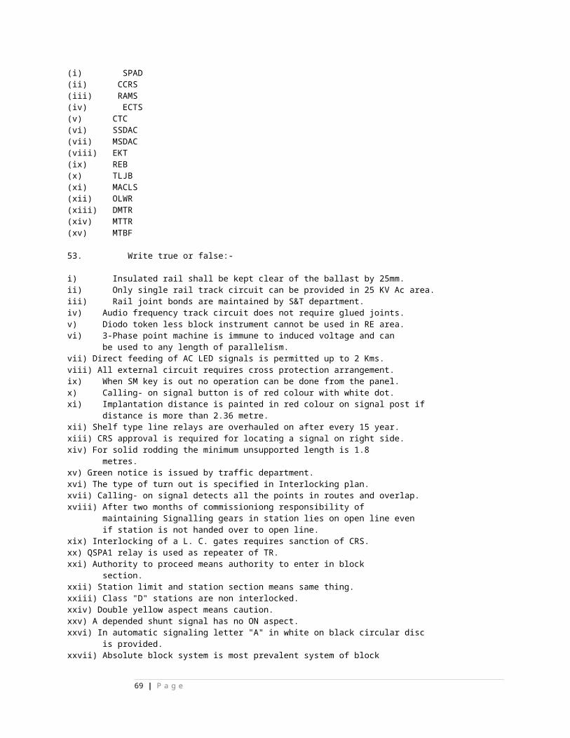
50 Compensator need not be used for lock bar operation up to the length of (a) 12M (b) 13M (c) 18.5M
( ) C
51 In compensator Acute /Obtuse angle crank arm sizes are (a) 375 x 235mm (b) 406 x 253mm (c) 300 x 225mm
( ) B
52 In compensator link rod size is (a) 346mm (b) 275mm (c) 165mm
( ) B
53 One compensator must be provided up the rod transmission (a) 346M (b) 210M (c) 265M
( ) B
5. FACING AND TRAILING POINT LAYOUTS:
54 Facing point lock plunger length in In and Out type of locking without cross slide is (a) 346mm (b) 755mm (c) 500mm
( ) C
55 Facing point lock plunger length in In and Out type of locking with cross slide is(a) 346mm (b) 755mm (c) 500mm
( ) B
56 Facing point lock plunger length in straight through type of locking is (a) 346mm (b) 755mm (c) 500mm
( ) B
57 Facing point lock plunger thickness is (a) 20mm (b) 38mm (c) 50mm
( ) A
58 Facing point lock plunger width in (a) 20mm (b) 38mm (c) 50mm
( ) C
59 Facing point lock plunger width in straight through type of locking is (a) 20mm (b) 38mm (c) 50mm
( ) B
60 Notch width in split stretcher bar in In and Out type of locking is (a) 23mm (b) 38mm (c) 53mm
( ) C
61 Notch depth in split stretcher bar in In and Out type of locking is (a) 23mm (b) 41mm (c) 53mm
( ) A
62 Notch width in split stretcher bar in straight through type of locking is (a) 41mm (b) 38mm (c) 53mm
( ) A
63 Notch depth in split stretcher bar in straight through type type of locking is (a) 23mm (b) 41mm (c) 53mm
( ) A
64The length of lock bar is (a) 42 ft (b) 38ft (c) 53ft
( ) A
65 Section of lock bar is (a) 50 x 50 x 6mm (b) 50 x 40 x 6mm (c) 50 x 50 x 20mm
( ) A
69 | P a g e
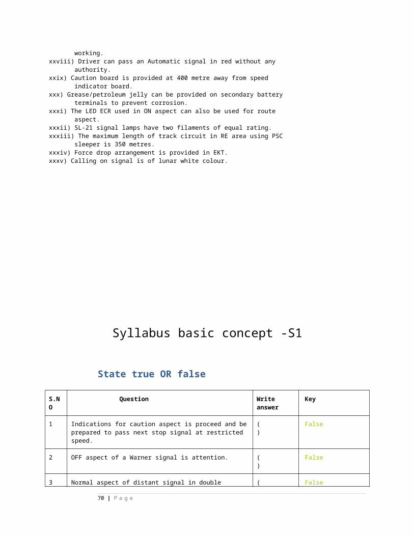
66 Inter distance between two lock bar clips shall not exceed (a) 1040mm (b) 1220mm (c) 1250mm
( ) B
67 Total lift of lock bar is (a) 35mm (b) 38mm (c) 44mm
( ) C
SIGNAL &WIRE TRANSIMMION:
68 The maximum spacing between the pulley stakes should not exceed. a) 8M (b) 10M (c) 4M
( ) B
69 The joints on the wire should be sufficiently clear of pulley stakes is about a) 2M (b) 6M (c) 4M
( ) A
LC Gates:70 SPL –Class L.C.Gates can be provided if the
TVU is more than a) 30,000 (b) 25,000 (c) 50,000
( ) C
71 A –Class L.C.Gates can be provided if the TVU is more than a) 30,000 (b) 25,000 (c) 50,000
( ) A
72 B –Class L.C.Gates can be provided if the TVU is more than a) 30,000 (b) 25,000 (c) 50,000
( ) B
73 Range of operation for lifting barrier type is a) 200M (b) 125M (c) 150M
( ) C
74 The open position of the lifting barrier shall be with in ------------degrees from the horizontal a) 80 to 90 (b) 75 to 85 (c) 80 to 85
( ) C
75 The closed position of the lifting barrier shall be within ----------degrees from the horizontal. a) 0 to 10 (b) -5 to +5 (c) 0 to 5
( ) A
70 | P a g e
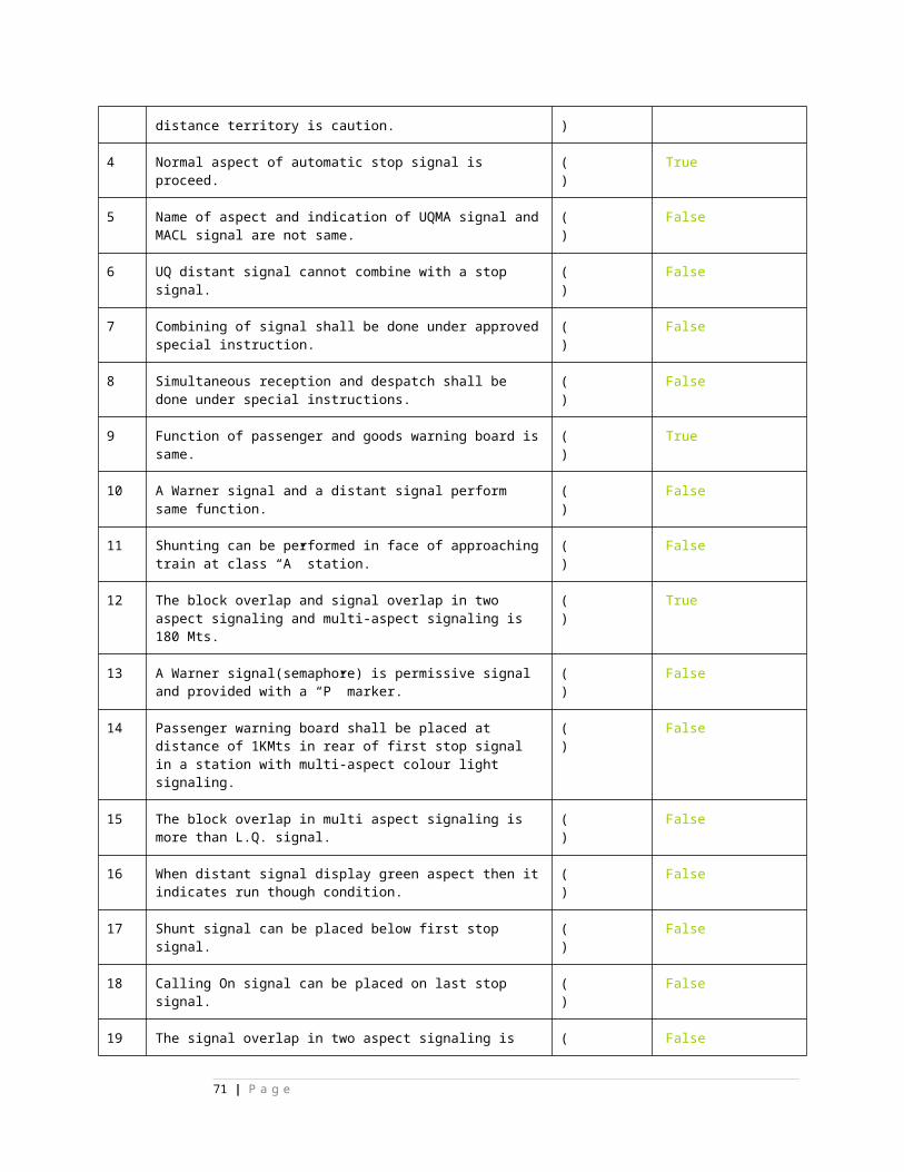
TRUE OR FALSE:1. LEVER FRAMES:
1 In Direct lever, Lever shoes are common and interchangeable
( ) T
2 For each standard, one baring cap is provided. ( ) T
3 Direct lever frame is available in bays of 5 levers and 7 levers.
( ) T
4 Shaft collars are provided to maintain lever pitch in catch handle lever frame
( ) T
5 Front tails are available as different strokes. ( ) T
6 In Direct lever Back tail is meant for carrying a 25kg weight for long distance signals.
( ) T
7 In Direct lever Quadrants are fixed on T-section quadrant supporting bars.
( ) T
8 Quadrants to hold the lever in Normal & Reverse positions.
( ) T
9 Quadrants to guide the lever during operation. ( ) T
10 Quadrants to maintain the lever pitch. ( ) T
11 Direct lever poses the problems of conflicting notches. ( ) T
12 In Direct lever locking box to attend maintenance and to attend failure.
( ) T
13 Conflicting of notches are almost completely avoided ( ) T
14 SA1101 is More mechanical advantages than SA530. ( ) T
15 D.W. Levers can be inserted on catch handle type to facilitate Outer, Warner & LSS operations.
( ) T
16 The locking will start to actuate by pressing the catch handle in ‘N & R’
( ) T
17 Mechanical advantage in catch handle lever is 5.6 ( ) T
18 Mechanical advantage in direct handle lever is 5.6 ( ) T
19 Pressing releasing the catch handle in catch handle ( ) T
71 | P a g e
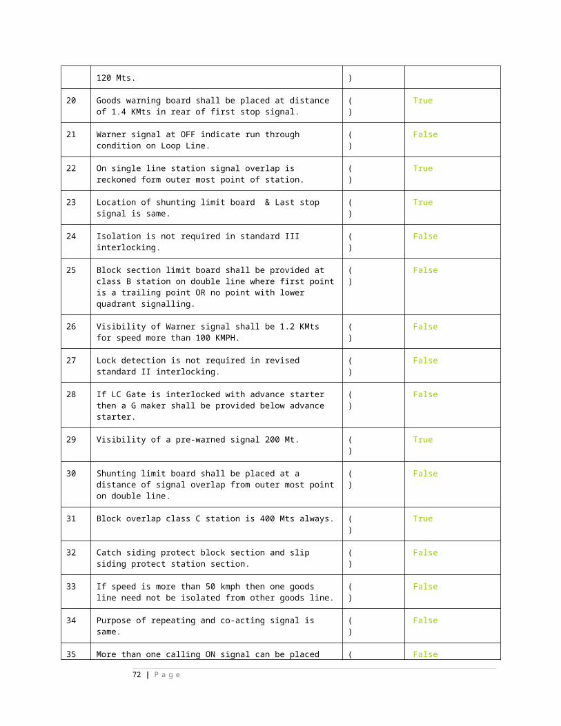
lever frame tappet will move 31mm
20 Clearance between catch block bottom and quadrant is 3mm
( ) T
21 Quadrants are fixed on rectangular quadrant supporting bar in catch handle lever frame
( ) T
22 Interlocking bar having the size of 16 x 12 mm ( ) T
2. CRANKS:
23 To divert the rod run up to 20° Relief crank is used ( ) T
24 Crank arm length 300mm x 300mm (12” x 12”) ( ) T
25 One of the arm is CURVED in Accommodating crank to facilitate connection & to accommodate cranks placed adjacent to it.
( ) T
26 Accommodating crank used in Outside lead out ( ) T
27 Accommodating crank 300mm x 300mm (12” x 12”) is used for lever pitch is 100mm(4”)
( ) T
28 Accommodating crank 350mm x 350mm (14” x 14”) is used for lever pitch is 125mm(4”)
( ) T
29 Accommodating crank arm sizes are 300mm x 300mm (12” x 12”) & 300mm x 400mm
( ) T
30 Changing the alignment of rodding run.i.e., 500mm or 600mm Straight Arm Crank is used
( ) T
31 In adjustable crank both the arms are equal. ( ) T
32 In adjustable crank length of the arms are 300mm x 450mm ( ) T
33 Signal crank is fixed at the base of signal ( ) T
34 Signal crank arm length are 225 mm x 300 mm ( ) T
35 Rod Joints are used for connecting levers, crank, points,etc., ( ) T
36 Flush Joint is used at vertical crank towards out side leadout.
( ) T
37 Screw Joint single end is used at lock plunger and lifting ( ) T
72 | P a g e
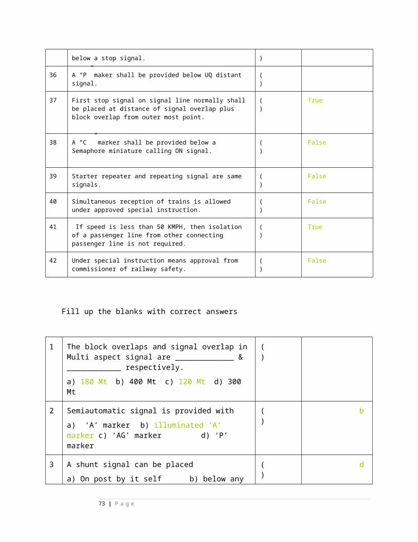
barried boom locking.
38 Screw Joint double end used for balancing of stroke at throw rod of point and lock bar.
( ) T
39 Eye Joint is used at radial guide, signal arm and circuit controllers
( ) T
40 Wide Joint is used where two rod joints required at one place.
( ) T
41 Lug Eye joint is use where two functions are operated from one lever.
( ) T
42 Swan Neck & Goose Neck joints are used for point detection rods.
( ) T
43 With turning of buckle in point adjusting screw we can shortening or lengthening of rodding. ( T )
( ) T
3. Rodding:
44 Tubular rod length is 33.5 to 34.5mm ( ) T
45 Tubular rod available in length 18’ ( ) T
46 Tubular weight is 2 lb/ft ( ) T
47 The rodding is supported on bottom rollers A small roller (top roller) is provided above the rods to prevent any undue distortion in vertical plane
( ) T
48 The height of the trestles is 38mm ( ) T
49 Point rodding shall be solid and shall be in accordance with IRS Spec.no.S5
( ) T
50 Point rodding shall be straight before being laid. ( ) T
51 With lever in the middle position joints and lug eyes must not be located less than 300mm from roller stand.
( ) T
52 Cranks and compensators should be so located in the main run that it leaves field side clear for additional rodding run.
( ) T
53 Cranks and compensators must not be fixed nearer a point rod roller than 900mm.
( ) T
54 When rodding running under tracks must be arranged to ( ) T
73 | P a g e
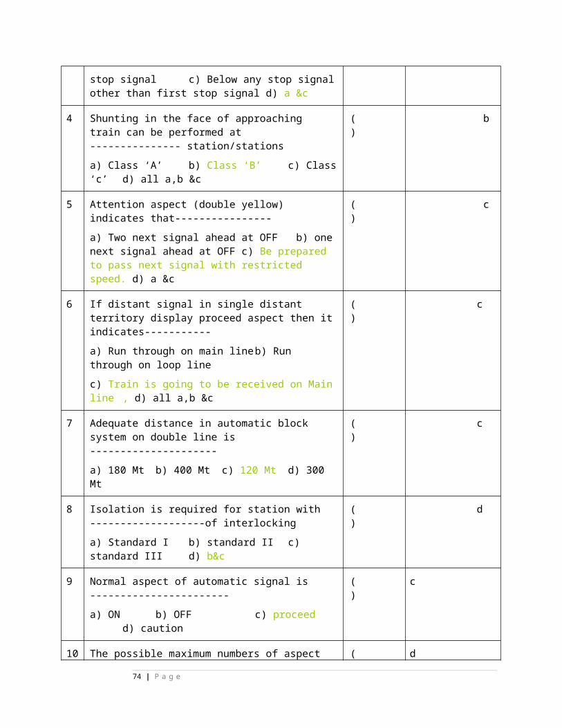
permit the standard spacing and packing of the sleepers.
55 The top of the rodding should not be less than 25mm below the bottom of the rails.
( ) T
56 Whenever possible, the running of rods under rail joints should be avoided
( ) T
57 Where a series of crossings have to be made each group must not be less than two sleepers apart.
( ) T
58 Rodding under L.C.Gates should preferably be run through standard reinforced concrete channels having mild steel cover plates at the road level.
( ) T
59 Where diversion in rodding run up to 20 degrees relief crank must be used.
( ) T
60 The top of roller standards adjacent to tracks shall not be fixed more than 64mm above rail level.
( ) T
61 The distance from the nearest rod to the center of the track shall not be less than 1905mm on BG lines.
( ) T
62 The distance from the nearest rod to the center of the track shall not be less than 1370mm on MG lines.
( ) T
63 Off-sets in the rodding should be limited 90mm ( ) T
64 Minimum length of the off-set should not be less than twice the amount of the off-set.
( ) T
65 Where more than one off-set is necessary, a guide should be provided.
( ) T
66 Joints in the rod run should be laid flat. ( ) T
67 Two bolts at joints preferable to provide one bolt with head on top and the other with head underneath.
( ) T
68 Welding of 35mm joints into rodding should be avoided. ( ) T
69 It is a rod used for connecting an interlocking lever to a vertical crank.
( ) T
70 Down rod length is more than 2M must be supported by a guide or guides in order to prevent buckling.
( ) T
71 Vertical crank is used in inside lead out ( ) T
74 | P a g e
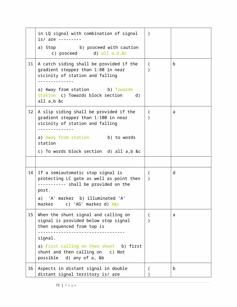
72 Accommodating crank is used in out side lead out ( ) T
4.ROD COMPENSATOR:( )
73 The rod compensator is installed to compensate the linear motion of rods (solid/tubular) due to temperature changes.
( ) T
74 A reverse crank used as compensator up to 120M transmission.
( ) T
75 The length of crank arm i.e, 300 mm (12”) is capable to take of up the expansion/contraction of 60M (200 ft) of rodding connected to it.
( ) T
76 This compensation range is limited to 22 ½° on either side of its means position as a safe margin.
( ) T
77 Compensator is able to convert pull motion into push and vice versa without alteration of stroke
( ) T
78 The initial setting of the crank arms should corresponds with prevailing temperature.
( ) T
79 The compensator should transmit working stroke unchanged although it
must reverse the direction.
( ) T
80 Where the normal crank is used the length of the shorter rod must be added to the length of the longer rod to find out the total length of straight line/trans.
( ) T
81 Where the reverse crank is used the length of the shorter rod must be subtracted from the length of the longer rod.
( ) T
82 There is no compensator in single wire transmission. ( ) T
83 Approximate linear expansion of rods 0.24” /100 Yds/10 F rise in temperature
( ) T
84 For crossover point one compensator should be provided between cabin and near end point and near end point to far end point one more compensator should be provided
( ) T
85 In rodding transmission there will be (2) Neutral points one at lever and other at function.
( ) T
86 The compensator is to provide exactly at centre of the two neutral points.
( ) T
75 | P a g e
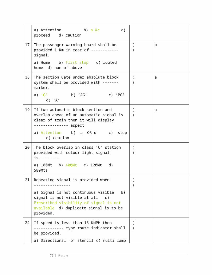
5. FACING AND TRAILING POINT LAYOUTS:
( )
87 Points are said to be facing when a vehicle or a train moving over them can be diverted from one track to the other
( ) T
88 In loose heel switch the front bolts of the fish plate at heel joint are to be kept sufficiently loose to allow for the easy movement of the switch.
( ) T
89 In fixed heel switch the force required for the operation of point is increased.
( ) T
90 In over ridding switches the tongue rail slides over the foot of the stock rail.
( ) T
91 The length of tongue rail in BG in 1:8 1/2 turnout is 4722mm(Straight Switch)
( ) T
92 The length of tongue rail in BG in 1:8 1/2 turnout is 7620 mm (Curved switch)
( ) T
93 The length of tongue rail in BG in 1:12 turnout is 7620mm (Straight Switch)
( ) T
94 The length of tongue rail in BG in 1:12 turnout is 9020mm (Curved Switch)
( ) T
95 The length of tongue rail in BG in 1:16 turnout (90R) is 11000mm (Curved Switch)
( ) T
96 The length of tongue rail in BG in 1:16 turnout (52Kg) is 13000mm (Curved Switch)
( ) T
97 points in the two tonque rails to move in union the tonque rails are tied through structure bars
( ) T
98 Leading stretcher bar having the size on BG is 6’ x 3” x ½”. ( ) T
99 Leading stretcher bar having the size on MG is 4’ x 2 1/2” x 3/8”.
( ) T
100 Leading stretcher bar should be fixed on BG at a distance of 13” from the toe of the switch rail.
( ) T
101 Leading stretcher bar should be fixed on MG at a distance of 15” from the toe of the switch rail.
( ) T
102 Following stretcher bar having the size on MG is 2’9” x 2 ( ) T
76 | P a g e
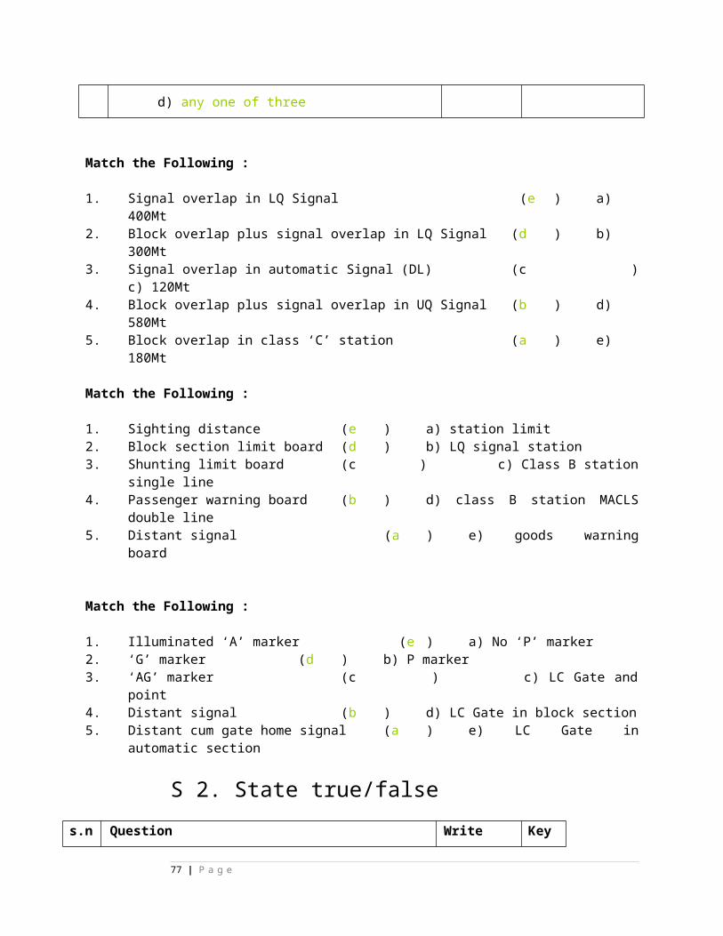
1/2” x 3/8”
103 Following stretcher bar having the size on BG is 4’8” x 3” x 1/2”.
( ) T
104 The following stretcher bar should be fixed on BG at a distance of 55” from the toe of the switch rail.
( ) T
105 The following stretcher bar should be fixed on MG at a distance of 54” from the toe of the switch rail.
( ) T
106 In point zone the track should be correct level and alignment
( ) T
107 In loose heel switch they can be thrown both ways with ease and can be housed against the stock rail by hand and remain there when the pressure is removed.
( ) T
108 In fixed heel switch they normally lie in the mid-position and flex equally in the normal and reverse positions.
( ) T
109 Tongue rail is chipped/cracked over a small length aggregating to 200mm with in the distance of 1000mm from its toe.
( ) T
110 The lock bar & the Plunger is provided to prevent the unlocking of points while the train is moving over it.
( ) T
111 Lock bar driving attachment to be fixed at 14” (350 mm) from the toe of lock bar.
( ) T
112 Three(3) lock bar stop are provided to ensure a fixed clearance below the rail level by 38 mm (1 ½ “)
( ) T
113 Each section of lock bar one stop to be provided. ( ) T
114 When the lock bar is normal, the FPL plunger should be clear by 12mm (1/2”) from the split stretcher bar.
( ) T
115 The clearance between stretcher notches and lock plunger shall not be more than 1.5 mm
( ) T
116 Detector is necessary to provide to detect the position of points and locks.
( ) T
117 The function of Detector is to prove the correct normal or reverse setting and correct locking of the point.
( ) T
SIGNAL &WIRE TRANSIMMION:( )
77 | P a g e
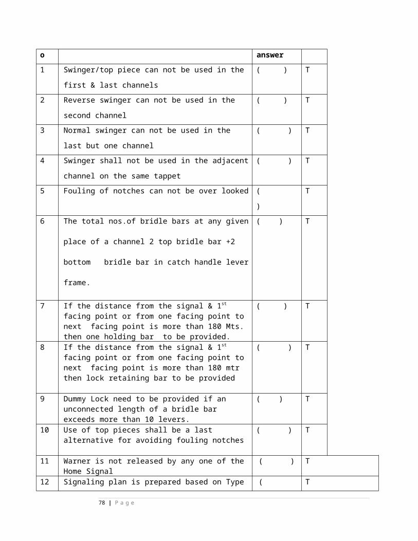
118 2-Aspect lower quadrant semaphore signals are generally worked by single wire transmission.
( ) T
119 Day aspect of signal is Arm position horizontal is ‘ON’ and 45 to 60 degrees below horizontal is ‘OFF’ position.
( ) T
120 In Mechanical signals spectacle arm is connected to the down rod
( ) T
121 The counter weight balance lever itself is fitted below on the post at a min. distance of 4 feet from the fulcrum of spectacle.
( ) T
122 A signal post consists of two tubes of section ‘140mm’ and ‘168mm’ outer diameter having each thickness of ‘7-9mm’.
( ) T
123 In tubular signal post the maximum height being only ’10.5M’.
( ) T
124 Where two or more lines diverge to the signals must be fixed on a bracket post.
( ) T
125 Dolls available in 4.9M,3.9M,2.9M,1.9M. ( ) T
126 Ladder on the signal post fixed at ‘225mm’ from the top of the post.
( ) T
127 B-Type spectical is commonly used on the Indian railways ( ) T
128 B-Type spectical is Much heavier than A-Type spectical ( ) T
129 In counter weight balance lever 92mm hole is connected to shunt signal.
( ) T
130 In counter weight balance lever 118mm hole is connected to ‘B’ type spectacle to get 90mm stroke for 45 degrees.
( ) T
131 In counter weight balance lever 154mm hole connected to ‘A’ type spectacle to get 130mm stroke for 50 degrees.
( ) T
132 The lowest transmission wire should be about 150mm clear from the ground.
( ) T
133 For running wire under level crossings, trenches are made along the level crossings, the top being covered with mild steel plates of suitable size and the inside surface of trench being plastered with cement.
( ) T
134 Sometimes wire run under L.C. Gates are made through pipes provided in the level crossings.
( ) T
78 | P a g e
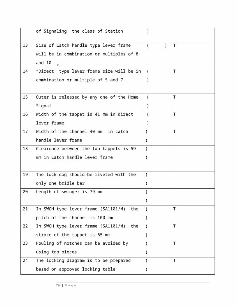
135 Facile stroke lever may be employed at a distance of 60 to 80M from the signal.
( ) T
LC Gates:( )
136 D –Class L.C.Gates provided for cattle crossing ( ) T
137 L.C.Gate Census will be taken once in three years ( ) T
138 Swing type gates are open either towards or away from the track.
( ) T
139 Mechanical lifting barrier type gates are operated by vertically
( ) T
140 The booms are provided according to the width of the road ( ) T
141 Lifting barrier drum is connected by D.W. transmission with gear on the winch.
( ) T
142 The movement of the lock wheel in lifting barrier winch is made less than one complete revolution.
( ) T
143 ‘E’ type key can be extracted only when the gate is closed ( ) T
144 A light fringe is usually fitted to provide a barrier between the boom and road surface , so that smaller animals of children may not pass through.
( ) T
145 Lifting barrier boom height from road surface should be maintained between 0.8M and 1M.
( ) T
146 The boom shall be either painted with 300mm bands of alternate black and yellow color or provided with approved type of retro-reflective strips.(
( ) T
147 It shall be ensured that Boom locking is effective and it is not possible to lift the boom by more than 10 degree from closed position.
( ) T
148 Rope drum (fixed on pedestal) not inter changeable for assembly from RH to LH and vice-versa.
( ) T
149 Tunion Brackets not inter changeable for assembly from RH to LH and vice-versa.
( ) T
150 Link assembly for bell not inter changeable for assembly from RH to LH and vice-versa.
( ) T
151 Pedestal on winch rope drum is mounted not inter ( ) T
79 | P a g e
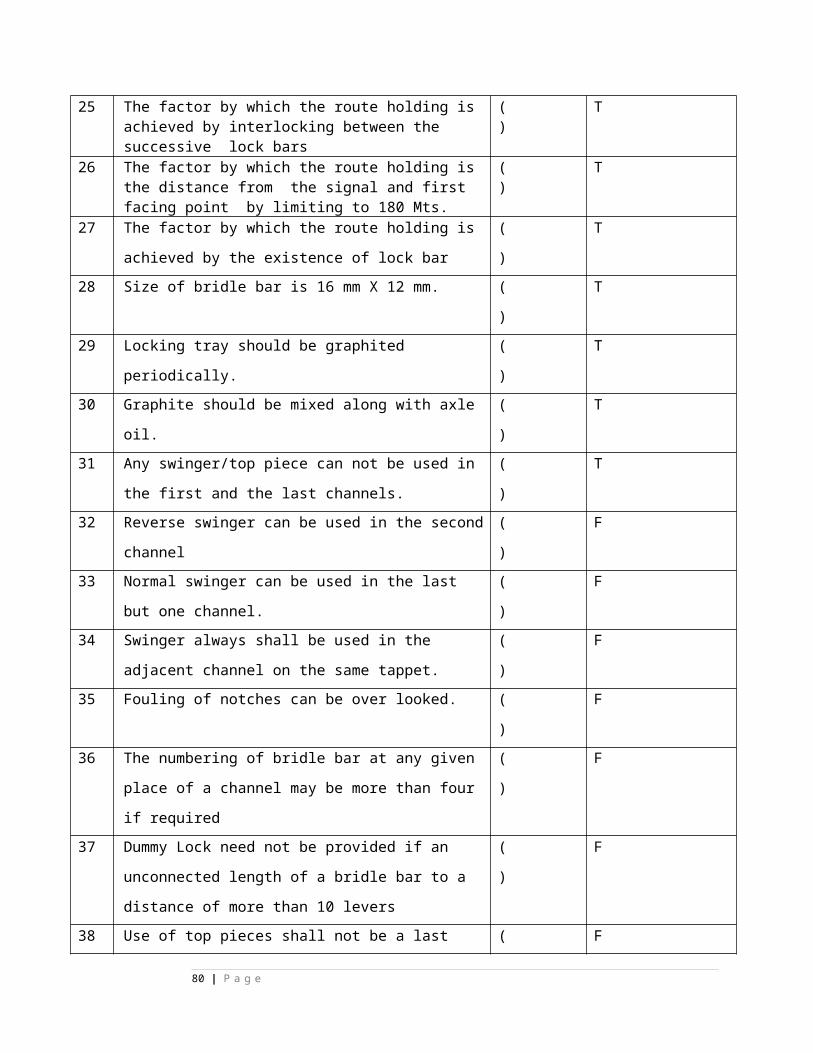
changeable for assembly from RH to LH and vice-versa.
152 The approach road should be in level. ( ) T
153 The gate equipments should be there as prescribed in the working rule
( ) T
154 The Whistle Board are provided on track while approaching L.C.Gate.
( ) T
155 The view for road users and the gateman of an approaching train is not obstructed.
( ) T
156 The telephone communication is in proper working order in gate lordge.
( ) T
157 The working instructions of the L.C.Gate is in the local language besides Hindi and English.
( ) T
158 At the time of taking cences Train, Motor vehicle, bullock carts&tongues taken as 1 unit
( ) T
159 At the time of taking cences Cycle rickshaw & auto rickshaw taken as ½ unit
( ) T
160 Visibility of manned gate is 5M. ( ) T
161 Fencing parallel to the track in L.C.Gate to be provided both side of track on either side of road is 15M
( ) T
162 Gate lodge to be provided at 6M from center of track ( ) T
163 Speed Breakers are provided at 20M from center of track on both sides
( ) T
164 Height gauge to be provided at 8M from center of track ( ) T
165 Gate post be provided at 3M from center of track ( ) T
166 TVU is more than 6000 or L.C.Gate visibility is poor –Un manned gate is converted into Manned gate.
( ) T
E- TYPE LOCKS:
167 Standard size of Key lock (E-type) –155X95X65mm ( ) T
168 E-type Key locks used for interlocking different functions ( ) T
169 E-type Key locks used for locking points ( ) T
80 | P a g e
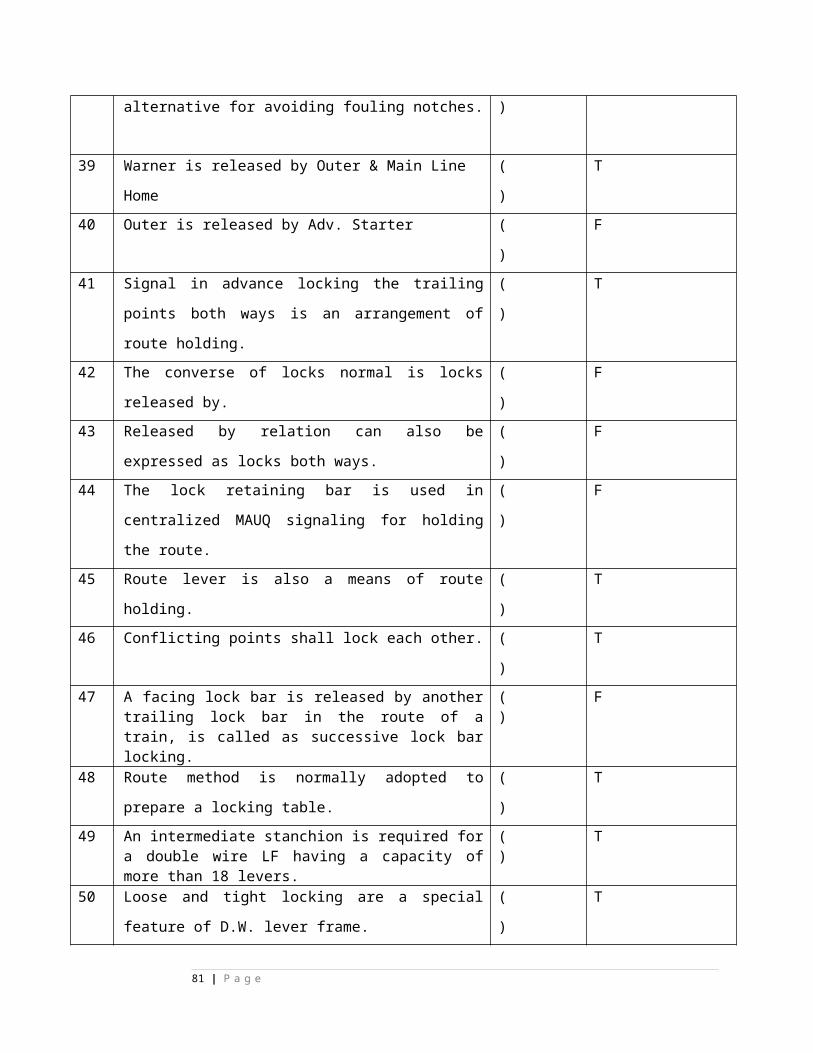
170 E-type Key locks used for locking boom locking levers ( ) T
171 E-type Key locks used for locking levers ( ) T
172 E-type Key locks used for block instruments locking ( ) T
173 The stroke of the E-type lock is 25mm. ( ) T
174 The no. of wards in the key is 3 ( ) T
175 A small hole is provided on center stud for sealing purpose. ( ) T
176 The function of the ward is to actuate the tumbler. ( ) T
177 The function of Lug & Feather is to operate the operating piece and to prevent the insertion of wrong key .
( ) T
178 Key turned clockwise lock bolt goes inside and key is locked.
( ) T
179 Key turned anti clockwise lock bolt comes out and key is came out.
( ) T
180 Material used for the tumblers is brass. ( ) T
181 Length of each key ward –6mm ( ) T
182 Length of each lug & feather –18mm. ( ) T
183 No.of locks available is 42 ( ) T
184 No.of ward combination is 24 ( ) T
S4-Double wire signalingState true/false
Chapter-2(Double Wire Levers)1 Double wire levers can be replaced
without disturbing other levers.( ) T
2 Double wire levers rotate through 1800, when operated from normal to reverse.
( ) T
3 The stroke transmitted to the tappet is 40mm when a lever is operated from normal to reverse.
( ) T
4 Locking tappet stroke of a clutch lever is 12 mm upwards when tripped at Normal.
( ) T
5 Locking tappet stroke of a clutch lever is ( ) T
81 | P a g e
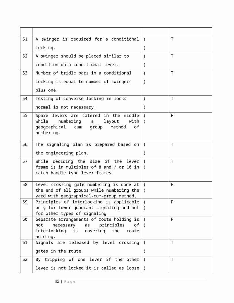
12 mm downwards when tripped at Reverse.
6 Locking tappet stroke of direct lever is 40 mm upwards while operating from Normal to Reverse.
( ) T
7 Locking tappet stroke of direct lever is 40 mm downwards while operating from Reverse to Normal.
( ) T
8 Locking tappet stroke of clutch lever is 40 mm upwards while operating from Normal to Reverse.
( ) T
9 Locking tappet stroke of clutch lever is 40 mm downwards while operating from Reverse to Normal.
( ) T
10 Locking tappet stroke of Rack&Pinion lever is 40 mm upwards while operating from Normal to Reverse.
( ) T
11 Locking tappet stroke of Rack&Pinion is 40 mm downwards while operating from Reverse to Normal.
( ) T
12Locking tappet stroke is 20 mm upwards while operating from Normal to Pull of the miniature lever.
( ) T
13Locking tappet stroke is 20 mm downwards while operating from Normal to Push of the miniature lever.
( ) T
14500 mm stroke Direct lever operates the signal without detector up to 1200 Mts.
( ) T
15 600 mm stroke Direct lever operates the signal without detector greater than 1200 Mts.
( ) T
82 | P a g e
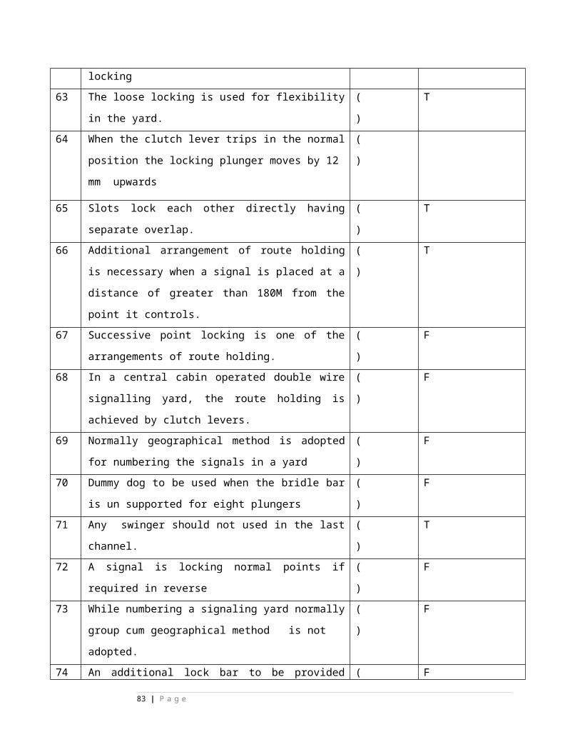
16
500 mm stroke Clutch lever operates the Points up to 500 Mts.
( ) T
17
600 mm stroke Clutch lever operates the Point up to 730 Mts.
( ) T
18
500 mm stroke Clutch lever operates the Detector up to 600 Mts.
( ) T
19
600 mm stroke Clutch lever operates the Detector up to 730 Mts.
( ) T
20
500 mm stroke Clutch lever operates the Signal with Detector up to 600 Mts.
( ) T
21
600 mm stroke Clutch lever operates the Signal with Detector up to 730 Mts.
( ) T
22
The stroke of the Rack& Pinion lever is 200 mm
( ) T
23
Rack& Pinion lever can operate the single end points up to 460 Mts.
( ) T
24
Rack& Pinion lever can operate the single end points up to 460 Mts.
( ) T
25
The Rack& Pinion lever can operate the double end points up to 275 Mts.
( ) T
26
The rope drum and the lever handle are rigidly fixed in the Direct lever.
( ) T
27
Conflicting functions can be operated through 3-position miniature lever.
( ) T
28
Rope drum and the lever handle are connected through a spring loaded clutch
( ) T
29
Rope drum can rotate independent of the lever handle in clutch lever
( ) T
30
85 Kgs tension difference in the transmission should not cause the clutch lever to trip
( ) T
Chapter-3(Coupling of levers)
31 Coupling of levers economizes cost of material of one transmission.
( ) T
32 Coupling of levers economizes cost of installation of one transmission.
( ) T
33 Coupling of levers economizes cost of maintenance of one transmission.
( ) T
34 Coupling of levers economizes cost of one compensator.
( ) T
35 Coupling of levers economizes cost of one signal mechanism when located on the same signal post.
( ) T
36 Coupling of levers economizes cost of installation ( ) T
83 | P a g e
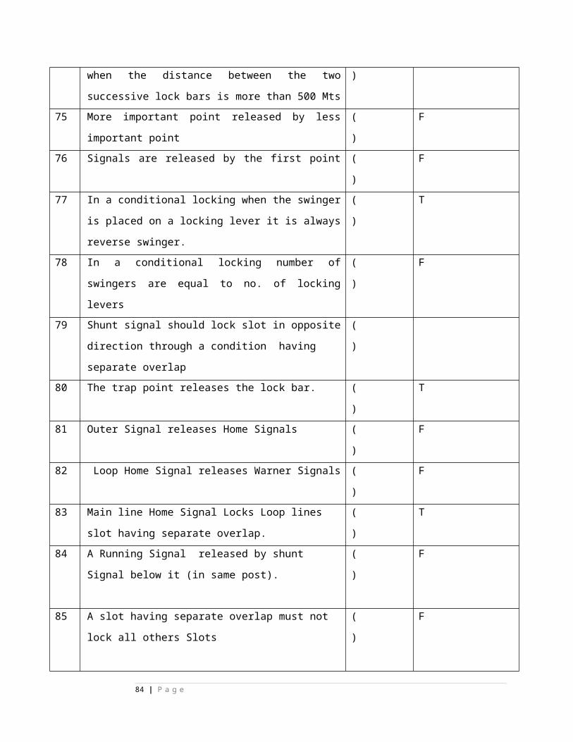
and maintenance of a signal mechanism.
37 The two levers should be adjacent in the lever frame for coupling.
( ) T
38 The two levers should bear consecutive numbers for coupling.
( ) T
39 Length of transmission between the two coupled functions should not be greater than 73 Mts.
( ) T
40 Push-Pull coupling to be adopted for the conflicting functions.
( ) T
41 Pull-Pull coupling to be adopted for the successive operated functions.
( ) T
42 Pull wires of both the coupling device levers are connected to the coupling device levers in Push-Pull coupling.
( ) T
43 Return wire of first operated lever and Pull wire of second operated lever are connected are connected to the coupling device levers in Pull-Pull coupling.
( T )
( ) T
44 L.Q. Main and Loop Line home signals are connected in Push-Pull coupling.
( ) T
45 L.Q. or U.Q. Ist loop and 2nd loop home signals are connected in Push-Pull coupling.
( T )
( ) T
46 A starter and a shunt below starter are connected in Push-Pull coupling.
( ) T
47 Two shunt signals one below the other are connected in Push-Pull coupling.
( ) T
48 A Home Signal and a Calling on signal below Home signal are connected in Push-Pull coupling. ( T )
( ) T
49 Normal and Reverse detectors are connected in Push-Pull coupling.
( ) T
50 Main line Home signal on a multiple aspect signalling ( ) T
84 | P a g e
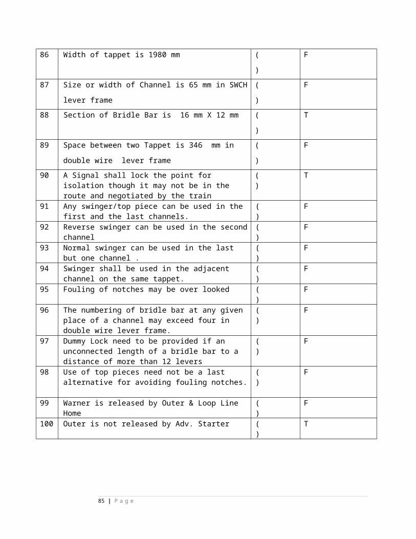
territory are connected in Pull-Pull coupling. ( T )
51 Outer and Warner Signals located on the same post are connected in Pull-Pull coupling. ( T )
( ) T
52 Hook lock is adopted to prevent the tripping of a coupled clutch lever.
( ) T
Chapter-4(Points)
53 The rack movement during unlocking of point is 51 mm.
( ) T
54 The rack movement during Point setting stroke 107mm.
( ) T
55 The rack movement during unlocking of point is 42 mm.
( ) T
56 The point mechanism movement during unlocking of point is 127 mm.
( ) T
57 The point mechanism movement during Point setting stroke 268mm.
( ) T
58 The point mechanism movement during unlocking of point is105 mm.
( ) T
59 The total movement of rack during its lever operation is 200 mm.
( ) T
60 Broken wire lock is adopted to prevent the operation of points when the last pull wire is broken
( ) T
61 Broken wire lock pawls must be tested once in every quarter.
( ) T
62 The width of the lock plunger on EFPL is 49.8 mm. ( ) T
63 The width of the locks on the EFPL is 38 mm independently for N and R___
( ) T
64 The two locks on the EFPL are staggered by 12 mm. ( ) T
65 The two locks on the EFPL are separated by the distance by 158 mm.
( ) T
66 Staggering of locks on EFPL proves correct setting of ( ) T
85 | P a g e
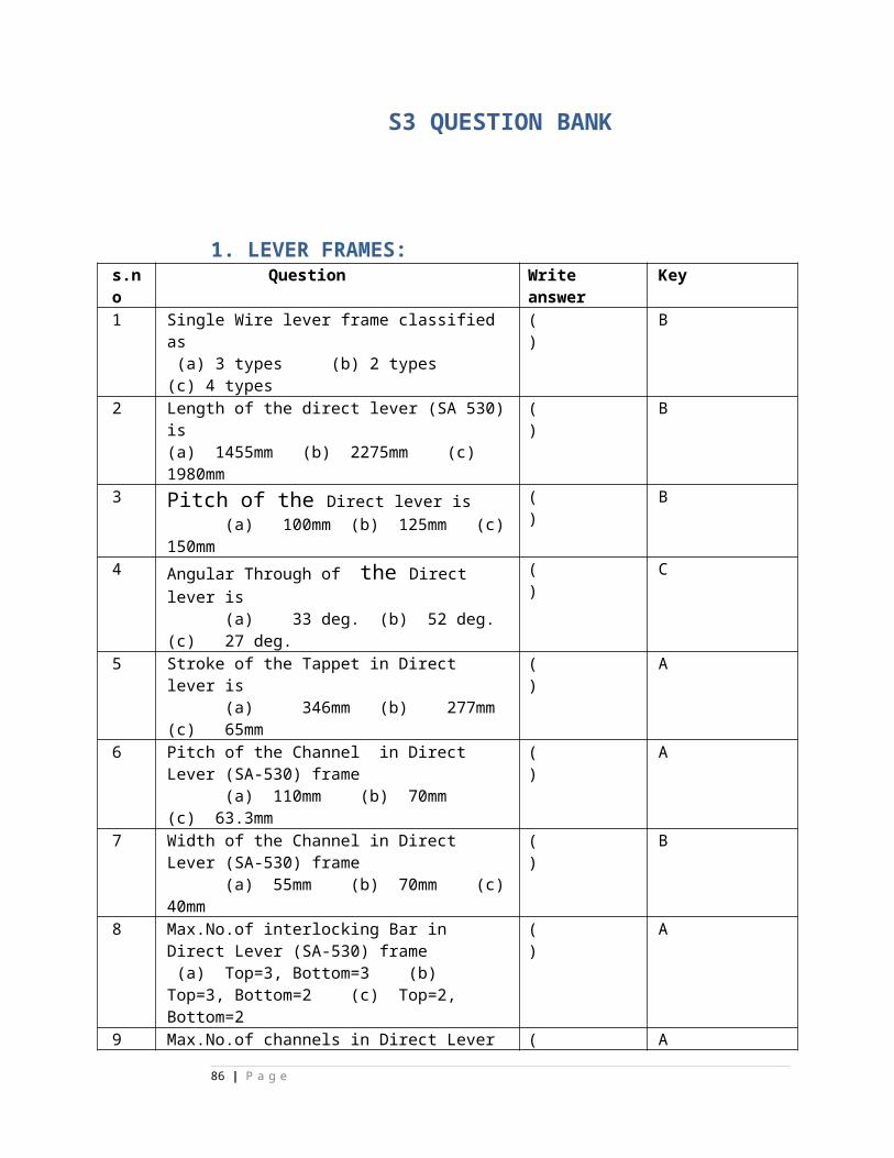
Points.
67 Separation of locks on EFPL facilitates economy in operation of point and lock.
( ) T
68 EFPL to be connected by the thumb rule “left in right out”
( ) T
69 The pitch of the notches on split lock stretchers with EFPL is 127 mm in BG
( ) T
70 The movement of cross slide when unlocked in EFPL is 16 mm.
( ) T
71 The movement of cross slide when relocked in EFPL is 16 mm.
( ) T
72 The movement of cross slide during point operation in EFPL is zero mm.
( ) T
73 PWI must bring the track on either side of the point to correct alignment.
( ) T
74 PWI must ease off rail joints on either side of points to be interlocked
( ) T
75 PWI must close the stock rail joints associated with lock bars.
( ) T
76 PWI must provide ballast fully and pack all points which are to be interlocked.
( ) T
77 PWI must take adequate measures to prevent creep in the vicinity points.
( ) T
78 PWI must provide creep and level pillars to prevent creep in the vicinity points.
( ) T
79 PWI must arrange the sleepers on adjacent track to facilitate rod/wire transmission to cross.
( ) T
80 PWI must provide and fix special timbers where required
( ) T
81 PWI must provide gauge tie plate correctly PWI must adjuste loose heel switches so that they can be thrown both way with ease
( ) T
82 Loose heel switches can be housed against the stock rail by hand and remain there when the pressure is
( ) T
86 | P a g e
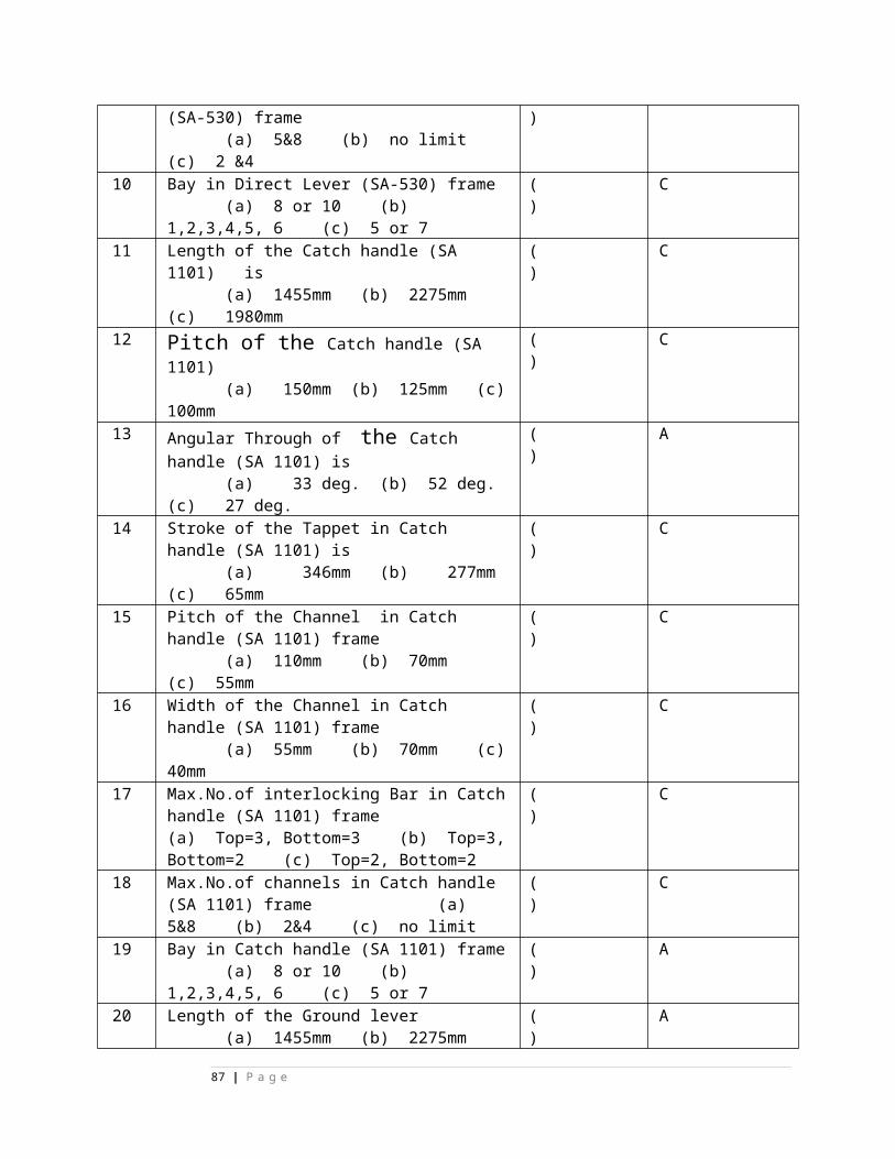
removed.
83 The planed surface of the switch rail should fully house against the stock rails for a sufficient length.
( ) T
84 Fixed heel switches lie in the mid-position and flex equally in the normal and Reversed positions. .
( ) T
85 Point should be fitted with fitted flexible stretchers so that they flex equally in the normal and reverse Positions
( ) T
86 Point should be fitted provided with a stop for the open position of a single switch layout.
( ) T
87 Facing point lock is fixed at 500mm from the gauge face in B.G.
( ) T
CHAPTER : 5 : SIGNALS
88 Signal mechanism should prevent inaccuracies in the transmission of lever strokes helps display of correct signal aspects.
( ) T
89 Signal mechanism should provide broken wire protection
( ) T
90 Signal mechanism should co-relate the down rod movement with that of the mechanism drum.
( ) T
91 Signal mechanism should make the maximum torque required for signal operation
( ) T
92 Signal mechanism should increase the range of signal operation & ease of lever operation.
( ) T
93 A single signal mechanism has one stop ( ) T
94 A coupled signal mechanism has two stops ( ) T
95 The cam paths are identical in the Universal signal mechanism
( ) T
96 Concentric path of Signal mechanism provides stability to the 'ON' and 'OFF' aspects of the Signal arm
( ) T
97 0 - 450 - 900 Signal Mechanism is used for working 3 aspects main line Home used for working 3 aspects
( ) T
87 | P a g e
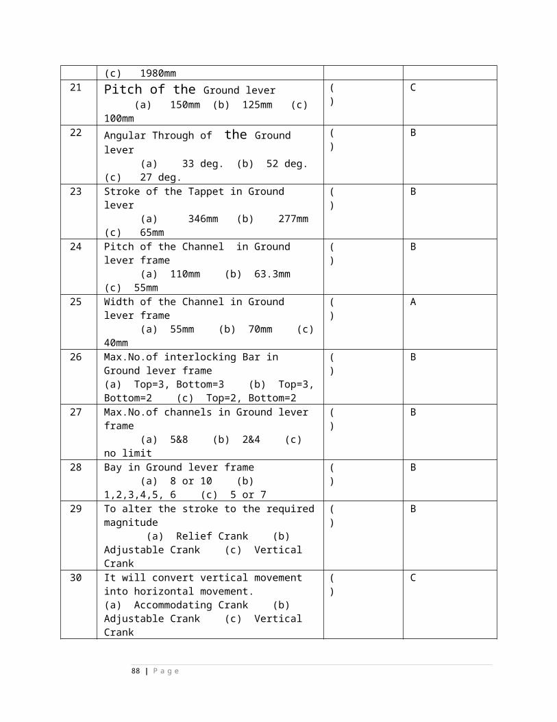
main line Home
98 450 - 0 - 900 Signal Mechanism is used for working the distant signal.
( ) T
CHAPTER: 6: DETECTORS
99 Detector is used to prove the position of the points ( ) T
100 Detector should be capable of being used in a signal transmission
( ) T
101 Detector is used to ensure the correct setting of the route.
( ) T
102 Length of Bottom rim 176 mm. ( ) T
103 Length of Detecting rim 869 mm. ( ) T
104 Length of Control rim 75 mm. ( ) T
105 Length of Locking rim 30 mm. ( ) T
106 Height of Bottom rim 10 mm. ( ) T
107 Height of Control rim 25 mm. ( ) T
108 Height of Detecting rim 10 mm. ( ) T
109 Height of Locking rim 10 mm. ( ) T
110 Detector detects the correct relation between switch and stock rails.
( ) T
111 Detector locks the points in the last operated position when the detector is operated.
( ) T
112 Detector locks the points in the last operated position if the detector transmission wire opposite this rim breaks.
( ) T
113 Detector permits the detector to be installed in a signal transmission.
( ) T
114 Locking Rim establishes correct relation between switch and stock rails.
( ) T
115 Locking Rim locks the points in the last operated position when the wire opposite this rim breaks.
( ) T
88 | P a g e
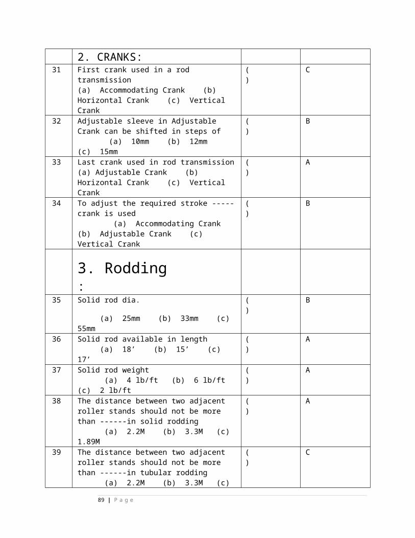
116 Control Rim proves the route ( ) T
117 Control Rim acts as a limiting stop in the event of wire breakage
( ) T
118 Control Rim helps the locking to lock the points in the last operated position in the event of wire breakage
( ) T
119 Control Rim helps the Locking rim to lock the points in the last operated position in the event of wire breakage.
( ) T
120 Control Rim helps the Detecting rim to lock the points in the last operated position in the event of wire breakage.
( ) T
121 Control Rim ensures the tripping of clutch lever. (T)
( ) T
CHAPTER : 7: COMPENSATORS
122 Double wire compensator introduces initial tension 68 kgs. in the transmission wires with the transmission at rest.
( ) T
123 The compensator levers should be locked during operation of the lever.
( ) T
124 Stretch in the intact wire incase of point transmission is 100 mm
( ) T
125 Wire breakage mark is indicated by 6 mm counter sunk depression
( ) T
126 Compensator locking stroke should not be greater than 25 mm
( ) T
127 Compensator levers are free to oscillate when the transmission is at rest
( ) T
128 Single compensator will have 3 pairs of wheels. ( ) T
129 Coupled compensator will have 4 pairs of wheels. ( ) T
CHAPTER : 8: TRANSMISSIONS
130 Double Wire transmission should be laid straight alignment.
( ) T
131 Inter distance between two pulley stakes should not ( ) T
89 | P a g e
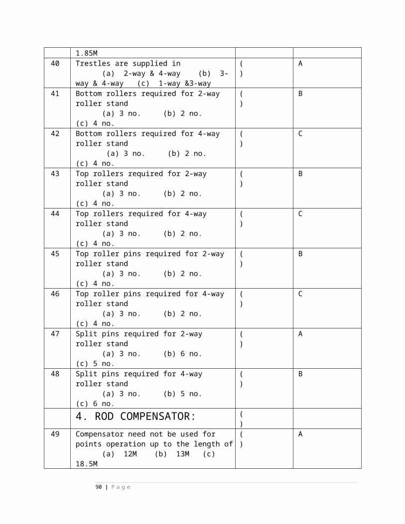
be greater than 20 Mts in case of Signals.
132 Inter distance between two pulley stakes should not be greater than 15 Mts in case of Points.
( ) T
133 Inter distance between two pulley stakes should not be greater than 15 Mts in case of Detectors.
( ) T
134 Inter distance between two pulley stakes should not be greater than 15 Mts in case of Signals with Detectors.
( ) T
135 Pulley Stakes should be properly leveled. ( ) T
136 Pulley Stakes should be rigidly fixed in the ground.
( ) T
137 Bottom most pulley should be 300 mm clear of ground in the D.W transmission.
( ) T
138 Fixing of Pulley stakes in the side drains should be avoided
( ) T
139 Wires and ropes must not scrap against walls protecting covers platform ramps, rails and sleepers.
( ) T
140 At level crossing gate transmission should run in RCC troughs and steel cover plates. (T)
( ) T
141 Transmission running in the diversion from straight up to 10 0 should run through diversion pulley.
(T)
( ) T
142 Transmission running in the diversion from 10 0 up to 30 0 should run through horizontal diversion wheel of dia 195 mm.
( ) T
143 Transmission running in the diversion greater than
should run through horizontal diversion wheel of dia 225 mm.
( ) T
1 25 KV AC 50 Hz single phase power supply for electric traction is derived from
( )
90 | P a g e
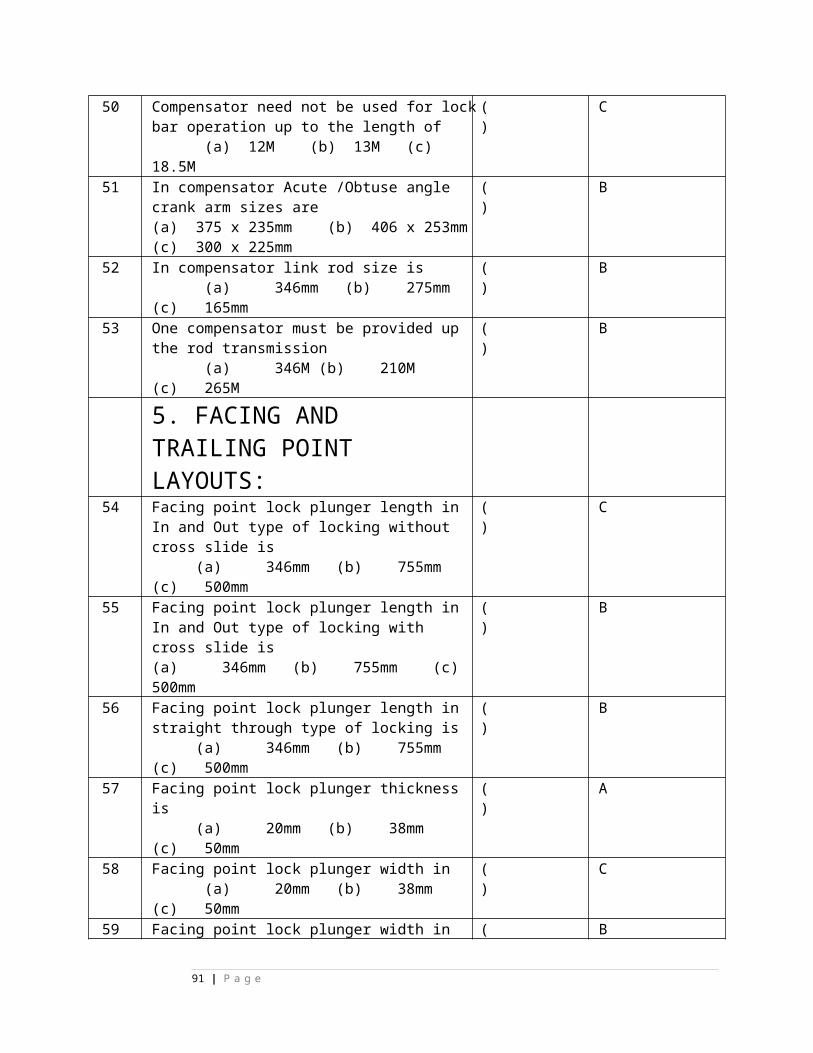
a) State grid b) Central grid c) Railway grid d) None 2 OHE with automatic tensioning is called
a) Regulated OHE b) Un-regulated OHE c) Ire-regulated OHE d) None
( )
3 The normal height of contact wire for regulated OHE above rail level is
a) 6.55m b) 7.59 m c) 5.55m d) None
( )
4 Under bridges, the height of contact wire on BG is
a) 5.55m b) 4.5 m c) 4.65m d) None
( )
5 On BG straight tracks, the catenary system is supported at maximum intervals of
a) 82m b) 62m c) 72m d) None
( )
6 Contact wire staggered on either side of centre line track on straight line tracks is
a) 200mm b) 300mm c) 29m d) None
( )
7 Contact wire staggered on either side of centre line track on curved tracks is
a) 300mm b) 400mm c) 600m d) None
( )
2.SIGNAL CLEARANCE AND VISIBILITY ( )8 For 25 KV A.C vertical clearance between any live part of
OHE and part of any fixed structure to a moving dimension is a) 300mm b) 400mm c) 320mm d) None
( )
9 For 25 KV A.C vertical clearance between any live part of OHE and part of any fixed structure to a stationary dimension is a) 300mm b) 270mm c) 320mm d) None
( )
10 For 25 KV A.C lateral clearance between any live part of OHE and part of any fixed structure to a moving dimension is a) 400mm b) 320mm c) 270mm d) None
( )
11 For 25 KV A.C lateral clearance between any live part of OHE and part of any fixed structure to stationary a dimension is
a) 400mm b) 320mm c) 220mm d) None
( )
12 Normal implantation of RE mast from centre line of nearest track
a) 3.5m b) 4.5m c) 2.5 m d) None
( )
13 The nearest part of the signal post from the centre line of track shall be
( )
91 | P a g e
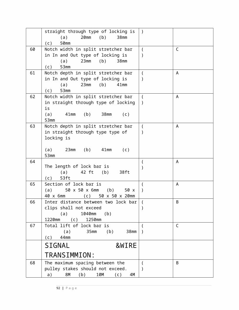
a) 3.5m b) 2.844 c) 2.5 m d) None 14 The distance between the signal and the mast in front of it shall
not be less than
a) 40m b) 50m c) 30m d) None
( )
15 The distance between the signal and the mast just in advance of signal normally
a) 40m b) 50m c) 10m d) None
( )
3. PROTECTION OF OPERATING AND S&T STAFF (T/F)16 For rod running under the track, the top of the rod shall not be
less Than 40 mm below the bottom of the rail. ( )
17 The distance between any OHE mast and the point rod shall not be less than 40 mm.
( )
18 Each rod shall be provided with an insulator immediately outside the cabin in the lead-out as close to the cabin as possible.
( )
19 An additional insulator shall be provided between the last adjustable crank and the point/lock bar
( ) T
20 If the rod transmission is more than 400 metres, additional insulators shall be provided on each rod at every 400metres
( ) F
21 The distance between two consecutive insulators on the same rod should be lesser than 300 metres.
( ) T
22 The wire insulator shall conform to IRS Spec. No. S47-74. ( ) T23 An insulator shall be provided in each wire near the gear of
operation ( ) T
24 A wire insulator to be provided at every 300mts of wire transmission
( ) T
25 The horizontal distance between two wires shall not be less than 60 mm
( ) F
26 The vertical distance between two wires shall not be less than 200 mm.
( )
4. EARTHLING ARRANGEMENTS27 The lever frame and other metallic frames of the cabin shall
be connected together to a separate earthing. ( ) T
28 The earthing shall not be provided at every location box where cable terminate.
( ) F
29 Earth connected for lightening discharger should not be more than 10 Ohms
( ) T
30 Earth connected for equipment should not be less than 10 Ohms.
( ) F
31 Earth connected Axle counter cable (screened) in ac electrified area should not be more than 1 Ohm.
( ) T
32 Where more than one earthing arrangements are employed, the distance between earthing electrodes shall not be less than 6metres.
( ) F
33 The clearance of equipment earths from system earths provided by the Electrical Dept. of Railways or any other administration shall not
( ) F
92 | P a g e
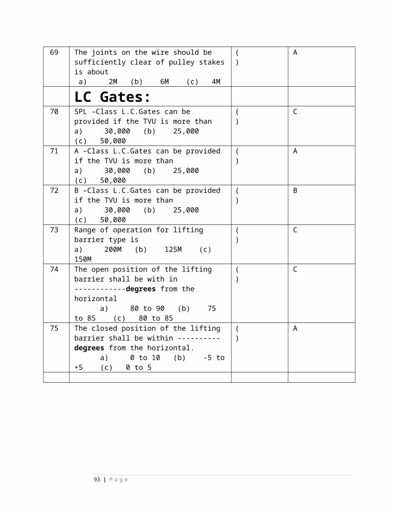
be less than 30 meters 5. LAYING OF SIGNALLING CABLES ( )
34 The cables laid parallel to the track buried at a depth of 2 m minimum.
( )
35 The depth of tail cables shall not be less than 1 m. ( )36 If cable is laid one meter from the RE mast its trench depth
shall not be more than 0.5m. ( )
37 If cable is laid in concrete/HDPE pipes up to 3 meters on either side of mast, the distance between the mast and trench can be reduced to 0.5 meters
( )
38 If the cable is laid at more than 0.5 meters depth the distance between trench and mast shall not be less not be less than 3 meters.
( )
39 In the vicinity of traction sub station the cables shall be laid on the side of the track opposite to the sub-station side
( )
40 Cables shall be laid at least 10 meters away from the switching station earthing
( )
41 During track crossings, the cables should cross the track at right angles
( )
42 During track crossings, the cables can cross the track under points and crossings
( )
43 During track crossings, the cables are to be laid in concrete pipes while crossing the track.
( )
44 During track crossings, the cables shall be buried at a depth of 1.0 metre below the bottom of the rail.
( )
45 At out side of station limits, the cable shall be laid 5 to 6 meters from the nearest centre line of the track.
( )
46 At with in station limits, the cable shall be laid not less than 5.5 meters from the nearest centre line of the track
( )
6. STRAY CURRENTS ( )47 Stray voltage in a track circuit shall not be more than 100mV. ( )48 The total stray current shall not exceed 10mA for a track
circuit length less than100m( )
49 The total stray current shall not exceed 10mA for a track circuit length more than100m
( )
7. ALTERATIONS TO TRACK CIRCUITS50 Only 09 ohms track relay should be used in AC RE area ( )51 Only single rail DC track circuit should be used in AC RE area. ( )52 In DC single rail track circuit feed end is protected by “B type”
choke.( )
53 Maximum length of DC track circuit with wooden sleepers is 250m.
( )
54 Maximum length of DC track circuit with PSC sleepers is 350m.
( )
55 Maximum length of DC track circuit with QBAT relay and choke at feed-end is 450m
( )
INDUCTION & ITS EFFECTS ON SIGNALLING ( )56 Electro static effects in signalling circuit can be nullified by ( )
93 | P a g e
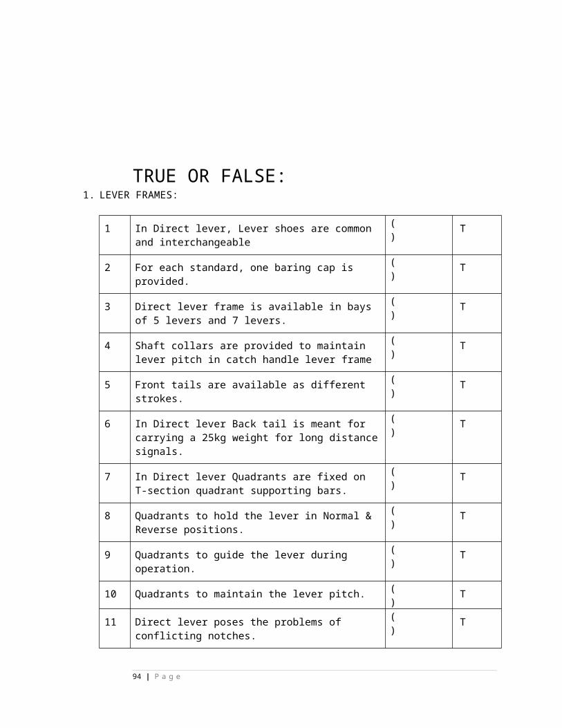
transferring the circuits in to Under ground cables. 57 Electro static effects in signalling circuit directly proportional to
Length of parallelism.( )
58 Electro static effects in signalling cable inversely proportional to distance of separation between catenary and cable.
( )
59 If whole of the return current passing the rails, then the voltage induced in a signaling cable which laid equal-distance from catenary & rail is 35v/km
( )
60 In screened cable by earthing of metallic sheath voltage induced in cable is reduced.
( )
61 Catenary current in old design is 600A D/L, 300A in single line.
( )
62 Short circuit current in old design is 4500A. ( )63 Rail impedance in old design is 0.6 ohms. ( )64 Rail reduction factor in old design is 0.56 for S/L 0.4 for D/L. ( )65 Cable screening factor in old design is 9.6 ( )66 A common design was adopted for single and double/multiple
track electrified sections in old design ( )
67 Due to electro-magnetic induction the voltage induced in signalling scrneed cable in old design is 35V/KM.
( )
68 Due to electro-magnetic induction the voltage induced in signaling un-scrneed cable in old design is 95V/KM.
( )
69 Max. Length of a circuit parallelism with screened cable is 3.5 km in old design.
( )
70 Max. Length of a circuit parallelism with un-screened cable is 1.9 km in old design.
( )
71 Glow voltage of 12v signal bulb on primary of signal transformer (110/12) is 21V.
( )
72 Glow voltage of 12v signal bulb on secondary of signal transformer (110/12) is 5V.
( )
73 Direct feeding range of signals with scrneed cable is 600m. ( )74 Direct feeding range of signals with un- scrneed cable in old
design is 330m( )
75 Shelf type line relays tested under BSS 1659, RE.Spec. 187/11, are only AC immunised
( )
76 In case of track relays Copper slugs & a magnetic shunt is used to make the relay to AC immunised.
( )
77 In case of Shelf type line relays no extra materials used to make relay AC immunised.
( )
78 AC. immunized Shelf type track relay is immune to 65VAC ( )79 QAT2 track relay is immune up to 50V AC. ( )80 Factor of safety in old design is 2.5. ( )81 QBAT track relay is immune up to 8OV AC ( )82 Shelf type line relays are immune up to 250V AC. ( )83 In case of siemens relays K-50B type relays only AC
immunized. ( )
84 Safe handling voltage in old design is 100V. ( )85 Remote feeding method is just extension of direct feeding. ( )86 Screening factor of Tele. Com cable is 0.1. . ( )
94 | P a g e
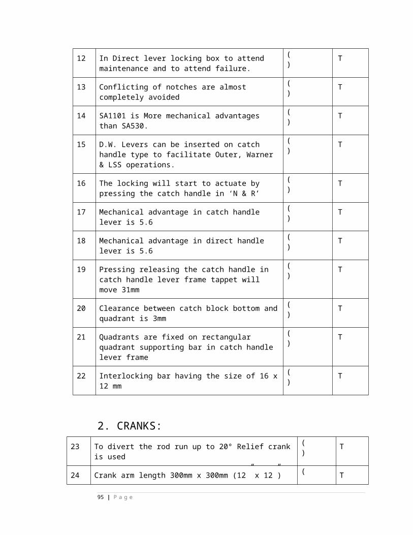
EVALUATION AND UPGRADATION OF EXISTING SYSTEM DESIGN-VARIOUS PARAMETERS
87 Catenary current in new design is 1000A D/L, 800A in single line.
( )
88 Short circuit current in new design on D/L 10000A. ( )89 Short circuit current in new design on S/L 6000A. ( )90 Rail impedance in new design is 0.701 Single Line ( )91 Rail impedance in new design is 0.561 Double Line ( )92 Rail Reduction Factor in new design for 0.3926 Single Line. ( )93 Rail Reduction Factor in new design for 0.566 Single Line. ( )94 Using of screened cable discontinued since we are unable to
maintain earth resistance as 0.2ohams to get 0.4 screening factor.
( )
95 New screening factor is 0.91. ( )Induced Voltages due to Higher Catenary Currents
96 Due to electro-magnetic induction the voltage induced in signalling cable in new design on D/L is 95V/KM
( )
97 Due to electro-magnetic induction the voltage induced in signalling cable in new design on S/L is 120 V/KM
( )
REVISED DESIGN OF SIGNALLING SYSTEM TO SUIT HIGH CATENARY CURRENTS
( )
98 Direct feeding range of signals on D/L in new design is 226m. ( )99 Direct feeding range of signals on S/L in new design is 180m. ( )100 Safe handling voltage in new design is 400V ( )101 Max. Length of a circuit parallelism on D/L in new design is
2.3 KM ( )
102 Max. Length of a circuit parallelism on S/L in new design is 2.1KM
( )
103 Factor of safety in new design is 3.5 ( )104 AC. Immunity level of GRS 5E point machine is 90V ( )105 Maximum permissible separation between Point Contractor
and GRS 5E Point Machine on single line is 400m ( )
106 Maximum permissible separation between Point Contractor and GRS 5E Point Machine on double line is 630m
( )
107 AC. Immunity level of IRS-24 point machine is 90V ( )108 Maximum permissible separation between Point Contractor
and IRS-24 Point Machine on single line is 910m ( )
109 Maximum permissible separation between Point Contractor and IRS-24 Point Machine on double line is 2.1KM.
( )
110 Maximum permissible separation between Point Contractor and SIEMENS IA type Point Machine on double line is 1.1KM.
( )
111 Maximum permissible separation between Point Contractor and SIEMENS IB type Point Machine on double line is 2.1KM.
( )
112 Maximum permissible separation between Point Contractor and SIEMENS IB type Point Machine on single line is 1650M.
( )
95 | P a g e
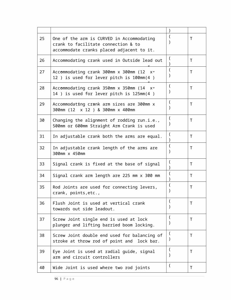
113 Maximum permissible separation between Point Contractor and SIEMENS IC type Point Machine on double line is 1850M.
( )
114 Maximum permissible separation between Point Contractor and SIEMENS IC type Point Machine on single line is 2.2 KM.
( )
115 AC. Immunity level of SIEMENS IB type Point machine is 300V
( )
116 AC. Immunity level of SIEMENS IC type Point machine is 500V
( )
117 As per RDSO specification No.S24/90 - for Electrical Point Machine non-trailable type, specifies the A.C. immunity level of Electrical Point Machine shall not be less than 160V RMS at 50 Hz
( )
1.Ans; a 26. Ans. T 51.Ans; T 76. Ans; T 101. Ans; F2.Ans; a 27. Ans. T 52.Ans; T 77.Ans; T 102Ans; T3.Ans; c 28. Ans. F 53.Ans; F 78.Ans; F 103.Ans; F4.Ans; c 29. Ans. T 54Ans; T 79 Ans; T 104.Ans; T5.Ans; c 30. Ans. F 55Ans; F 80.Ans; T 105. Ans; F6.Ans; a 31 Ans. T 56. Ans; T 81. Ans; T 106.Ans; T7.Ans; a 32. Ans. F 57.Ans; T 82.Ans; F 107Ans; F8.Ans; c 33. Ans. F 58.Ans; T 83. Ans; T 108.Ans; T9.Ans; b 34..Ans; F 59.Ans; F 84 Ans; F 109.Ans; F10.Ans; b 35.Ans; F 60. Ans; T 85. Ans; T 110. ANS;T11.Ans; c 36.Ans; T 61 Ans; T 86. Ans; T 111.Ans; T12.Ans; c 37.Ans; T 62Ans; F 87Ans; T 112. Ans; T13.Ans; b 38.Ans; T 63. Ans; F 88.Ans; F 113. Ans; F14.Ans; c 39.Ans; T 64. Ans; T 89. Ans; T 114.Ans; T15.Ans; c 40.Ans; F 65Ans; F 90.Ans; T 115.Ans; T16.Ans; T 41Ans; T 66Ans; T 91.Ans; T 116. Ans; F17.Ans; T 42Ans; F 67.Ans; T 92.Ans; T 117.Ans; T18. Ans. T 43.Ans; T 68.Ans; F 93Ans; F19.Ans. T 44.Ans; T 69.Ans; T 94 Ans; T20. Ans. F 45Ans; F 70.Ans; F 95. Ans; T21.Ans. T 46.Ans; T 71.Ans; T 96.Ans; T22. Ans. T 47.Ans; T 72.Ans; F 97.Ans; F23. Ans. T 48.Ans; T 73.Ans; T 98. Ans; F24.Ans. T 49.Ans; T 74.Ans; F 99.Ans; T25.Ans. F 50Ans; T 75. Ans; T 100. Ans; T
SECONDARY CELLSIf the load current is 4A and backup time required is 10Hrs then
recommended capacity of Lead Acid Cell is ______B) 60 AH C) 80 AH D) 120 AH
Maximum permissible load on 120AH capacity Lead Acid cell is ________
96 | P a g e
B) 20 A C) 10 A D) 24 AVoltage of the fully charged lead acid cell is ________ V
B) 2.2 V C) 2.3 V D) 2.4
End point voltage of the lead acid cell is _______ V B) 1.9 V C) 2.0 V D) 2.2 V
Specific gravity of the discharged lead acid cell is ___________ in terms of hydrometer reading. B) 1200±5 C) 1210±5 or 1220 D) 1240±5
Specific gravity of the fully-charged Lead Acid cell is ________ in terms of Hydrometer reading. B) 1200±5 C) 1210±5 D) 1240±5
MULTIPLE CHOICES:
STATE TRUE or FALSE
1 If the load current is 8A and backup time required is 10Hrs then recommended capacity of Lead Acid Cell is 80AH
( ) F
2 During the preparation of electrolyte always add acid to distilled water only, but not water to acid.
( ) T
3 In Lead Acid cells, electrolyte level should be maintained at 12mm to 15mm above the plates.
( ) T
4 If the Lead acid cells are continuously used in “FLOAT Charging” then equalising charge must be given once in 3 months.
( ) T
5 In Lead Acid cells, Boost charging current must given at the rate of C/10 Amp
( ) T
6 LMLA cells are preferred over VRLA cells for signaling application.
( ) T
97 | P a g e
BATTERY CHARGER
MULTIPLE CHOICES:1 Battery charger of 24V can charge maximum ______ no. of cells.
A) 24 B) 12 C) 13 D) 14
( ) D
2 Recommended current rating of Battery charger for charging 120AH Lead Acid cell is _______________. A) 12 A B) 24 A C) 30 A D) 40 A
( ) C
3 For charging of 200 AH cells _____________ amp capacity charger is required. A) 20 A B) 24 A C) 30 A D) 40 A
( ) D
4 Boost charging voltage of the lead acid cell is ______
A) 2.2 V B) 2.3 V C) 2.4 V D) 2.7 V
( ) C
5 Initial charging voltage of the lead acid cell is _________
A) 2.2 V B) 2.3 V C) 2.4 V D) 2.7 V
( ) D
6 Float charging voltage of the Automatic battery charger (IRS: 86/200) is adjustable from ________ per cell. A) 2.12 to 2.3 V B) 2.2 to 2.3 V C) 2.12 to 2.4 VD) 2.12 to 2.7 V
( ) A
7 Chargers used for Axle counter installations, the r.m.s ripple shall be less than______. A) 10mV B) 50mV C) 100mV D) 200mV
( ) A
8 Chargers used for Axle counter installations, the peak to peak noise voltage shall be less than 50mV. A) 10mV B) 50mV C) 100mV D) 200mV
( ) B
9 Battery charger working in manual mode, the charger output voltage shall be _____ V per cell. A) 2.2 V B) 2.25 V C) 2.3 V D) 2.4 V
( ) B
10 Battery charger generates low battery alarm when the battery voltage falls to ______ V per cell. A) 1.95 V B) 2.0 V C) 2.2 V D) 2.25 V
( ) A
11 Battery charger generates start DG set non-resettable alarm when the battery voltage falls to 1.90V/cell. A) 1.9 V B) 2.0 V C) 2.2 V D) 2.25 V
( ) A
12 Battery charger isolates battery from the load when the battery voltage falls to ________V per cell. A) 2.0 V B) 2.15 V C) 2.2 V D) 1.8 V
( ) D
STATE TRUE or FALSE
98 | P a g e
1 60V battery charger is having the provision for charging the 30 or 31 or 32 no. of cells.
( ) T
2 Battery charger can able to give the constant output voltage with the input Voltage variation of 160VAC to 270VAC.
( ) T
3 110V battery charger is having the provision for charging maximum 55 no. of cells.
( ) F
4 In IRS: 86/2000 Battery charger the boost charging current control & float voltage adjustment is possible only in Auto mode.
( ) T
IPS SYSTEMSTATE TRUE or FALSE
1 Blanking of signals due to power supply failure can be effectively and economically prevented by using IPS.
( ) T
2 In IPS system, inverters are configured with (1+1) configuration. ( ) T3 All the DC-DC converters except for Relays (internal) of IPS
system are used in (N+1) load sharing configuration.( ) T
4 In IPS system, Inverter output is used for the load of DC Track circuits.
( ) F
5 In case of IPS system, normally only one Battery bank is used. ( ) F6 An inverter is used in IPS system to convert the A.C. power into
D.C. power.( ) T
7 DC-DC converters of IPS system for Relays (internal) are used in (N+1) load sharing configuration.
( ) F
8 SMRs of IPS system are provided with in (N+2) load configuration.
( ) T
9 In IPS system Inverter-2 will be automatically connected to the load, when Inverter-1 output is failed.
( ) T
10 In IPS system CVT or AVR will be automatically connected to the load, when Inverter-1 and Inverter-2 output is failed.
( ) T
11 With IPS System, DG set is not required ( ) F12 Class B and Class C arresters are used in IPS for stage1 and
stage2 protection( ) T
13 IPS system generates Start D.G set audio-visual alarm with 50% depth of discharge of Battery bank.
( ) T
14 IPS system generates Stop D.G set audio-visual alarm whenever FRBC / SMR change over to float mode from boost mode.
( ) T
OBJECTIVE: BATTERIES:
Fill up the blanks with suitable words:
1 I.S. Specification number of battery graded Con.Sulphuric acid __________ (IS266-1977)
( )
99 | P a g e
2 I.S. Specification number of Battery graded Distilled water is__________(IS1069)
( )
3 I.S. Specification number of acid resistant paint is___________. ( )4 I.S. Specification number of Plante positive Lead acid cells
__________.( )
5 I.S. Specification number of pasted plates Lead Acid cells __________.
( )
6 I.S. Specification number of tubular positive Lead Acid cells __________.
( )
7 I.S. Specification number of Dry Leclanche cell is ____________. ( )8 I.R.S. Specification number of Auto/Manual battery charger
___________.( )
9 I.S. Specification number of Ni- Cd rechargeable pocket plated batteries is______________.
( )
10 I.R.S. Specification of Low maintaince lead acid batteries is__________.
( )
11 I.R.S. Specification number of SMF lead acid batteries is_____________.
( )
12 Voltage of a fully charged Lead Acid cell is______________. ( )13 Lead Acid cell can be discharged up to voltage of
____________.( )
14 Separators prevent ____________ between _______ & __________ plates in Lead Acid cell.
( )
15 The active materials in Lead acid cell are ___________, ________ &_____________.
( )
16 A 400Ahcapacity Lead Acid cell can be charged with a maximum current of ___________.
( )
17 Capacity of any Lead Acid cell is given in___________ with ________ Hrs rating.
( )
18 Electrolyte used in Lead Acid cell is _______ _____________. ( )19 Specific gravity of battery graded Con. Sulphuric Acid is
____________.( )
20 Initial charging current rate can be taken as _______% of its capacity in case of L,A, cells if manufacturer’s rating is not available.
( )
21 Maximum electrolyte temperature allowed during Initial charging of Lead Acid Cell is__________ºC.
( )
22 Electrolyte for lead acid cell can be prepared by adding _________ to __________ in small quantities.
( )
23 To avoid lead corrosion on battery connectors and terminals apply ______________ or _______________.
( )
24 Per cell voltage in case of Float charging is_________. ( )25 Per cell voltage in case Boost charging is___________. ( )26 The rate of self discharge in case of Lead Acid cell can be taken
as______ per AH.( )
27 Specific gravity of electrolyte varies with temperature at the rate of ___________ per 1ºC.
( )
28 The measuring instrument used for measuring Specific gravity is _____________.Sulphation can be identified by ____________ & ___________.
( )
100 | P a g e
29 Sulphation in Lead Acid cell increases ___________________ in Lead Acid Cell.
( )
30 In VRLA cell/battery the compensation of distilled water is by _________________.
( )
31 In VRLAB the pressure inside is regulated by ___________. ( )32 ____________ indicates the fully charged condition of Lead Acid
cell.( )
33 Internal resistance is maximum at _________ Specific gravity. ( )34 If temperature increases the specific gravity _____________ in
Lead Acid Cell.( )
35 After discharge, both the plates becomes ________ in Lead Acid Cell,
( )
36 The level of electrolyte above the plates should be always_________.
( )
37 Buckling of plates in Lead Acid cell is due to _________________ of plates.
( )
38 During Initial charging, the charging can be stopped only after ____ % of AH input is fed.
( )
39 The insulating pieces between positive and negative plates of a cell are called as _____________.
( )
40 The ratio of Acid to Distilled water to get 1200 Specific gravity electrolyte is______: ________.
( )
41 Voltage of a fully charged Nickle Cadmium cell is __________ . ( )42 Electrolyte used in Ni-Cd cell is _____________. ( )43 The active material on +ve plates in Ni-Cd cell is
_________________.( )
44 The active material on –ve plates in Ni-Cd cell is _________________.
( )
45 When Ni- Cd cell is discharged the Cadmium Hydroxide is reduced to __________________.
( )
46 In Ni-Cd cell, the Lithium hydroxide is added to electrolyte to ________________________.
( )
47 In Ni-Cd cell the plate grids are made from _________ _______ ________ _______________.
( )
48 Specification number of sealed cylindrical Ni-Cd cell is ______________.
( )
49 Capacity range of pocket plated Ni-Cd cell is ________________.
( )
50 The material used for separators in Ni-Cd cell is __________________.
( )
51 In Automatic Battery charger the output controlling device is ______________.
( )
52 Recommended current rating of charger for an 80AH battery with maximum permissible load of 12 Amps is ___________ Amps.
( )
53 Automatic battery charger under S-86/20000 specification can supply constant output voltage for A.C. input variation from ________V to ______ V.
( )
54 The rectifier circuit converts ___________ to ___________. ( )55 In case of Ferro resonant type automatic regulator for sudden
changes of input voltage or Load variation the response time is ( )
101 | P a g e
< ____________.56 In case of Ferro resonant type automatic regulator short circuit
protection is achieved by__________________ winding.( )
57 Voltage of a Solar cell is ____________ . ( )58 Charging current should be reduced when the battery starts
_____________.( )
59 Per cell voltage in case of Initial charging is_____________. ( )60 Per cell voltage in case of Boost charging is____________ ( )61 Per cell voltage in case of Float charging is_____________. ( )62 In case of Ni-Cd cell/Battery , charge input during first charge
should be __________ capacity of C5 AH.( )
63 ____________ are formed on the plate surphase , when Sulphated.
( )
64 Note down ___________ ____________ of each cell periodically.
( )
65 The material used for grids in MFB is __________________. ( )66 Topping up with distilled water in case of HDP plante Lead Acid
cells can be done once in ________months.( )
67 Terminal voltage of a fully discharged Ni-Cd cell is____________.
( )
68 When the Lead Acid cell is discharged completely, both the plates are converted into ____________ .
( )
69 The material used for grid structure in Lead Acid cell is______________.
( )
70 The insulation resistance of Mains transformer in battery charger should be more than ____________ M Ohms.
( )
71 In battery charger the current rating of Diodeds & SCR’s should be more than ____________ current flowing through them.
( )
72 The resistors power rating, used in battery charger should be __________.
( )
73 Voltage rating of capacitors used in chargers should be _______٪ above peak value.
( )
74 I.S. Specification number of HRC fuses is ______________. ( )75 Additional protection for chargers rated above 50 Amps shall be
provided with extra _____________ & ___________.( )
76 Ripple in D.C. output of battery charger should be less than_________٪
( )
77 Psophometric noise voltage in the output of a battery charger should be less than __________ Mv.
( )
78 The charger works in ________________ condition, if battery draws current less than 5% of its set value.
( )
79 The charger switches to ____________ when the battery draws currewnt more than 8-12% of the set current.
( )
80 Power factor of an Automatic battery charger must be above _______ lagging in all modes.
( )
81 No load AC input current shall be __________ value in case of Automatic battery charger.
( )
82 In Automatic battery charger the gate pulses for SCR’s is generated by ____________ circuit.
( )
83 In case of Automatic battery charger permitted variation in the ( )
102 | P a g e
output voltage over the entire range of input AC supply variation is ___________.
84 The grid structure of Lead Acid cell is made from _________________ or ________________alloy.
( )
85 Permissible raise in temperature above amient for Mains Transformer shall be __________.
( )
86 ON/OFF switch in battery charger shall be of _____________ pole type.
( )
87 The range of voltage control potentio meter in a battery charger shall be___________ to __________ V.
( )
88 In chargers above 50Amps rating series fuses to be provided for ______________ & ____________ elements.
( )
89 Specific gravity of electrolyte ____________ when temp decreases.
( )
90 Specific gravity correction factor per 1ºC is___________. ( )91 Equavalising charging is necessary to a battery connected in
___________ charging .( )
92 Use of ballast resistance in a battery charger is_______________.
( )
93 Check _________, __________, ________ for every 8Hours during initial charging
( )
94 Voltage of a Secondary cell depends on ______________ & ______________
( )
95 A 300 AH 10H battery can supply 20 Amps current for ___________ number of hours.
( )
96 IS Specification of a plante positive type cells is ________________ (IS-1652)
( )
97 IS Specification of Tubular positive type cells is _____________. (IS-1651)
( )
98 Specific gravity correction factor per 1ºC is _____________. ( )99 Negative plates are one more than the positive plates to provide
______________________.( )
100 Vent holes are provided in vent cap to for ____________ to ______________.
( )
101 The level of electrolyte in Lead Acid Cell is indicated by ____________________.
( )
102 The level of electrolyte inside the cell is always be _______ '' above the plates.
( )
103 The current inside the cell is carried by _____________. ( )104 The separators used in VRLAB are made from
_______________.( )
105 The grid in VRLAB are made from _______________ alloy. ( )106 The normal battery operating temperature is ________ºC. ( )107 SMF cells need much addition of distilled water due to
_________________ principle.( )
108 The electronic device which converts AC to DC is called as _______________.
( )
INVERTER:
103 | P a g e
109 Inverter converts ____________ to ___________. ( )
110 Efficiency range of an inverter should be within _________% to __________%,
( )
111 Output frequency of inverter should be _____________ ( )
112 In case of solid state inverter no load current shall not exceed _______% of full load current.
( )
113 Inverters of 500VA and above shall be provided with __________& __________ indications.
( )
114 The PWM IC number used in 500 Watts inverter is ______________.
( )
115 SG2535A is an _______________________________ I.C. ( )
116 EMI/RFI filter is connected on the ______________ side of the inverter.
( )
117 The inverter automatically shuts off when battery voltage goes below ___________ volts.
( )
118 The inverter will be in OFF condition when mains A.C. supply is ___________.
( )
119 The Oscillator frequency inside the SG3525A I.C. is ________ Hz.
( )
120 The power amplifier stage in inverter uses _______________ as power amplifier device.
( )
121 MCCB means____________ _______ __________ ___________.
( )
122 The changeover time to inverter during Mains power failure is in ________
( )
123 Shut- off input to IC SG3525A is given to pin No_______________.
( )
124 The insulation resistance of the inverter shall not be less than_________M Ohms under 40ºC.
( )
Solar cells:
1 Solar cells converts __________ energy to _________ energy. ( )
2 Solar panel is a combination of _________ connected in ___________ & __________ fashion.
( )
3 The solar cell is made from __________ & ______________ materials.
( )
104 | P a g e
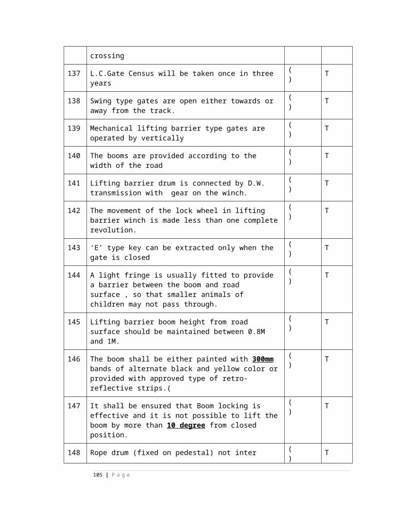
4 Generation of electricity from Sun light is called as________________
( )
5 A typical Solar cell is nothing but __________________ ( )
6 Conversion efficiency of a Silicon solar cell is _________________.
( )
7 Falling of dust, dirt and snow, decreases the Solar arrays ___________
( )
8 A solar panel is installed inclined at an angle equal to the _____________ of the plane.
( )
9 Surface of solar cell is coated with ________________ coating to increase _____________.
( )
10 Open circuit voltage of a solar cell is _______ V. ( )
Say TRUE or FALSE:
1 Hexagonal shape of a solar cell provides more utilization area ( )
2 Solar cell converts “Electrical energy” into “Solar energy” ( )
3 Solar panel is a combination of solar cells ( )
4 Voltage of each solar cell is 1.2 V ( )
5 Solar cells are made from semiconductor materials ( )
6 The semiconductor material used for solar cell is Aluminium ( )
7 Solar cell produces pollution ( )
8 Efficiency of a Solar cell is very high ( )
9 Solar system is having longer life ( )
10 Conventional Lead Acid Cells are suitable for Solar panel ( )
Uninterrupted power supply (UPS):
105 | P a g e
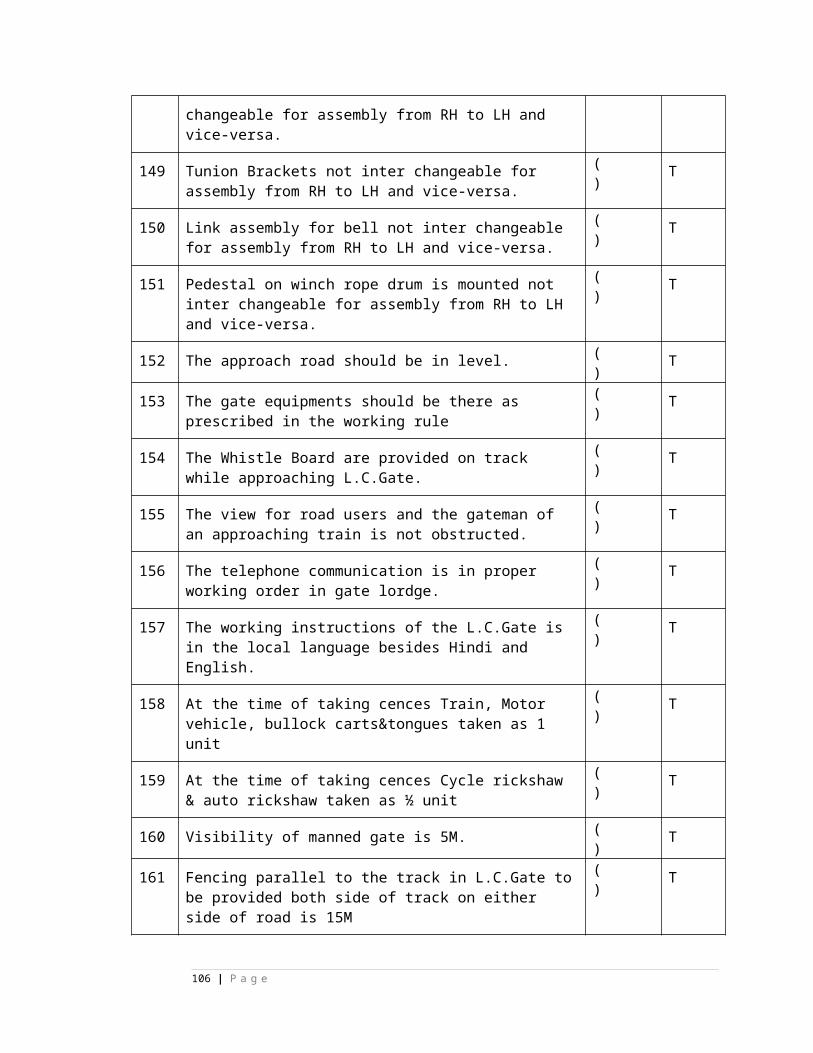
11 In Off-Line UPS the inverter is ON only when the mains supply
__________.
( )
12 Change over time in ON-line UPS is _____________ mS ( )
13 ____________ of batteries are preferred in UPS. ( )
14 Regulation of output voltage is done by using __________
principle in UPS
( )
15 Normal PF rating of UPS is ________ ( )
16 In ON-Line UPS the battery will be always in ___________
condition.
( )
17 __________ or __________ device are used in Power Amplifier
stage of UPS.
( )
Say TRUE or FALSE:1 In Off-Line UPS the inverter is always in ‘ON’ condition ( )
2 In ON-Line UPS there is no change over time ( )
3 In put to UPS is A.C ( )
4 In OFF-Line UPS the relay will be OFF condition when AC input
is present
( )
5 UPS backup time can be increase by increasing the capacity of
the battery
( )
106 | P a g e
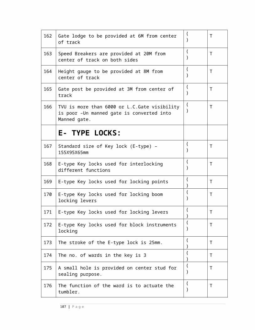
6 Only a single transformer is sufficient in ON-Line UPS ( )
7 In OFF-Line UPS the battery will be charge only when the
inverter is ON
( )
8 For UPS with rating higher than 2KVA IGBT device is used in
power amplifier stage
( )
Choose correct answer:
1)
1 The backup time in UPS depends on,
A) Load B) Voltage C) Batter capacity D) all the three
( )
2 The type of UPS used in Medical side is,A) ON-Line B) OFF-Line C) Line interactive D) Non of the above
( )
3 Malfunctioning of UPS is avoided by incorporating,A) Fuse B) EMI/RFI filter C) Only filter D) controlling device
( )
4 4) Input to an UPS is, A) Battery B) AC mains voltage C) rectifier output D) non of above
( )
SMPS:
1 The switching & controlling element in SMPS is ___________________. ( )
2 The output voltage of SMPS is regulated by, A) converter transformer B) pulse width of controlling pulses C) input rectifier D) filter circuit
( )
3 SMPS of 100 Amps rating requires 3 SMR modules of each rating ,A) 50Amps B) 25 Amps C) 100 Amps d) any value
( )
4 The switching device used in SMPS is ,A) transistor B) IGBT C) MOSFET D) Diode
( )
5 The switching device in SMPS operates at,A) above 100KHz B) VF range C) 10-100 KHz D) 10-100MHz
( )
107 | P a g e
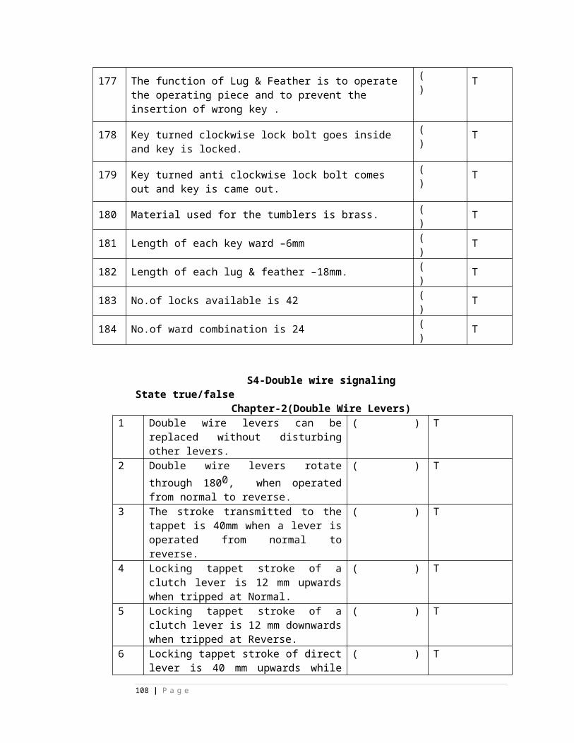
6 The converter transformer in SMPS operates at low frequency ( )
7 The switching device in SMPS will be in always On condition ( )
8 SMPS is a modular type power supply ( )
Say TRUE or FALSE :-
1 The grids and separators will be effected if the specific gravity of electrolyte isbelow 1.240
( )
2 The internal resistance is minimum at specific gravity 1.240 in Lead Acid cell ( )
3 Capacity of a Lead Acid cell is directly proportional to its length of service ( )
4 The Initial charging current is less than normal charging current ( )
5 Electrolyte can be prepared by adding distilled water to Sulphuric Acid ( )
6 During Initial charging add only distilled water ( )
7 The battery which is kept continuously under “Float charging” should be given “ Equavalising charge” to compensate low or uneven Sp. Gravities of cells
( )
8 Buckling is one of the causes for internal short circuit ( )
9 The internally short circuited cell gasses freely ( )
10 Buckling of cell plates takes place due to excessive charging or discharging ( )
11 Shedding means falling of active material from the plates ( )
12 Do not allow the batteries to get fully discharged ( )
13 Boost charging charges the battery quickly ( )
14 The internally short leads to reverse polarity of the cell ( )
15 Formation of lead corrosion at cell terminals causes high resistance ( )
16 Rate of Trickle charging is 100 mA/AH capacity. ( )
108 | P a g e
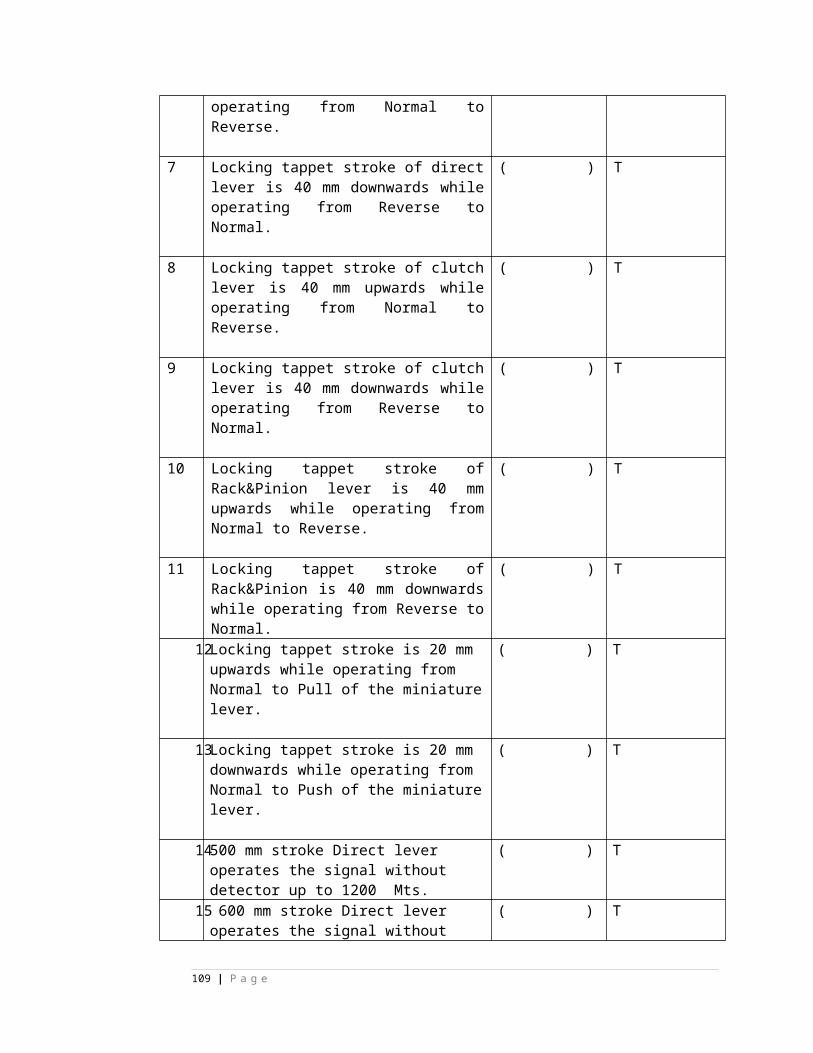
17 Distilled water to be added in MFB ( )
18 Initial charging is a constant potential type of charging ( )
19 Gas recombination principle is used in maintaince free sealed L.A. battery ( )
20 Constant potential method is used to charge VRLA battery ( )
21 Voltage of a fully charged Ni-Cd cell is 2.1 V ( )
22 Distilled water to be added during initial charging to maintain the level ( )
23 Initial charging can be stopped before 50% of charging is completed ( )
24 Trickle charging is given to a fully discharged battery ( )
25 Boost charging is a constant potential type of charging ( )
26 The nominal cell voltage of a MFB lead acid battery is 2V ( )
27 Calcium alloy is having lower self discharge and increased conductivity ( )
28 Maximum electrolyte temperature allowed during charging is 100ºC ( )
29 The active material on the positive plates in Lead Acid cell is Spongy Lead ( )
30 Con. Sulphuric Acid is used as electrolyte in Lead Acid Cell ( )
31 Secondary cell voltage depends on the number of plates ( )
32 Ampere-Hour efficiency can be increaswd by controlling thje charging current ( )
33 Efficiency of a secondary battery is defind as the ratio of input divided by output
( )
DG Set:
1 Fill up the blanks with suitable words: ( )
2 The D.G. Set converts _____________energy into ______________ energy. ( )
109 | P a g e

3 In Diesel engine the ___________ is compressed in the cylinder. ( )
4 During ______________ stroke the power is transmitted to the crank shaft. ( )
5 The liquid fuel is sprayed into the cylinder by ____________. ( )
6 The out-put voltage of generator is controlled by controlling the ______________ of the shaft.
( )
7 The speed of the Diesel engine is controlled by providing ________________ on the engine shaft.
( )
8 The fuel used in Diesel engine is __________ oil. ( )
II. CHOOSE CORRECT ANSWER: ( )
1 The paper element of fuel filter is to be changed for every,
A)250 Hrs B) 500 Hrs C) 800 Hrs D) 50 Hrs
( )
2 Speed of the prime mover at full load is,
A) 1200 RPM B) 1560 RPM C) 1570 RPM D) 1500 RPM
( )
3 Engine starts and stops due to,
A) Fuel tank filled completely B) air in fuel lines C) piston defective D) non
of the above
( )
4 Compression ratio in Diesel engine is,
A) 16:1 B) 1:16 C) 10:1 D) 5:1
( )
5 Both the valves are closed during.
A) suction stroke B) compression stroke C) exhaust stroke D) non of the
above
( )
6 The valves in DG set are lifted by,
A) Cams on cam shaft B) piston C) crank shaft D) non of the above
( )
7 Engine starts but stops after some time due to,
A) Air in fuel line B) Oil tank is full C) piston faulty D) non of the three
( )
8 The fuel in diesel engine is ignited by,A) spark plug B) Compression C) piston D) Non of the three
( )
9 Lubricating oil in Diesel engine is located at,A) Tank B) piston C) Sump D) non of the three
( )
10 The fuel filter in Diesel engine is to be replace after,A) 500 Hrs B) 800 Hrs C) 1000 Hrs D) 500 Hrs
( )
110 | P a g e
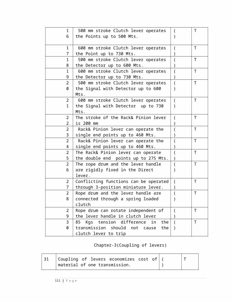
III. Say TRUE or FALSE:-
1 Spark ignition system is required in diesel engine ( )
2 Fuel tank in diesel engine should be cleaned for every 250 hours of working ( )
3 Excessive fuel consumption is due to incorrect value of fuel timing ( )
4 The exhaust valve opens during power stroke ( )
5 Governor throttle regulates the amount of fuel supplied to the engine ( )
6 The diesel engine is to be overhauled for every 500 Hours ( )
7 The power is transmitted to alternator by camshaft in diesel engine ( )
8 The valves are opened by livers in diesel engine ( )
IV) MATCH THE FOLLOWING:
1 Injector A) low ESR filter capacitors ( )
2 Piston B) stores mechanical energy ( )
3 Radiator C) charge/discharge system ( )
4 Fly wheel D) Cooling system ( )
5 SMPS E) compress the air ( )
6 Linear power supply F) spray liquid fuel ( )
7 Micro wave station G) low efficiency ( )
8 clean the air filter H) after 250 Hrs ( )
9 change the air filter I) for every 50 hrs element ( )
10 Clean the sump J) after 800 Hrs ( )
111 | P a g e
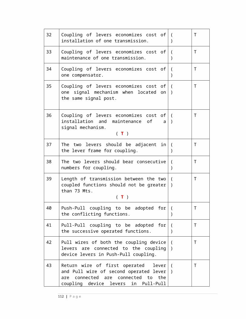
S.No. Question
1 When cascading is used in aspect control circuit them signal lamp to be used is/are--------a) SL18 b) SL21 c) SL35 d) a&c both
2 The signal lamp to be used in directional route indicator is/are ------------------a) SL33 b) SL13 c) SL35 d) SL25
3 Locking provided in siemens and IRS point machine is ---------------- type.a) Rotary b) straight troughc) in & out d) clamp type
4 The signal lamp to be used in multi-lamp route indicator is/are ------------------a) SL33 b) SL13 c) SL35 d) SL25
5 The signal lamp to be used in shunt signal (parallel) is/are -----------------a) SL33 b) SL13 c) SL35 d) SL25
6 When point is not set , not lock OR both then ------------------ makes.a) RC contact b) NC contact c) RD contact d) a&b both
7 The signal lamp to be used in shunt signal (series) is/are ------------------a) SL65 (60 voilt/25 watts) b) SL13 c) SL35 d) SL25
8 The signal lamp terminal voltage shall not be more than ------------- of rated voltage.a) 90% b) 98 %c) 80 % d) 12 %
9 The rating of SL 21 signal lamp is-----------------------.a) 12 volts 24 watts & 12 volts 16 watts b) 12 volts 33 watts & 12 volts 16 watts c) 12 volts 24 watts & 12 volts 24 watts d) 12 volts 16 watts & 12 volts 16 watts
10 The effective focal length of combination of inner colour lens and clear outer lens is ----- a) 17 to 21mm b) 140mm c) 100mm d) 5mm
112 | P a g e
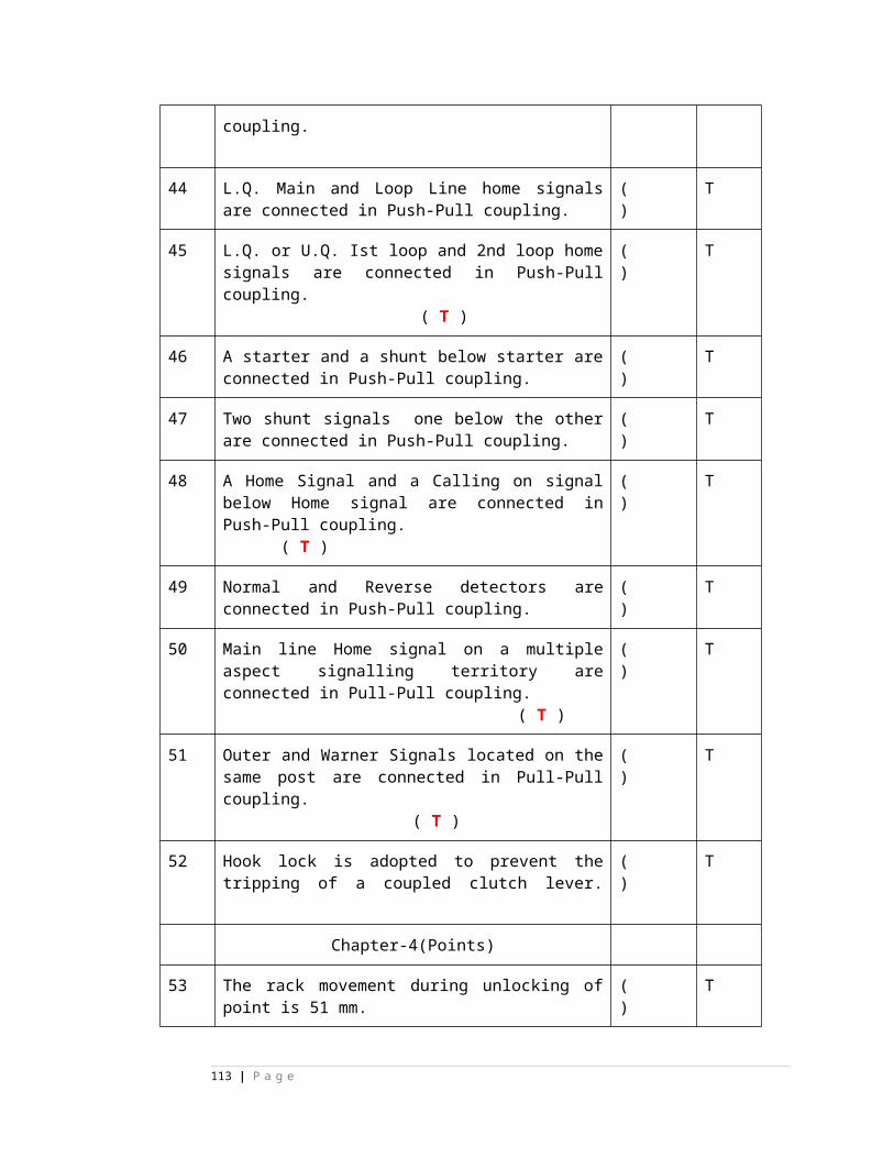
11 Lamp to be used in ON aspect of signal is/are a) SL21 b) SL35Ac) SL35B d) a&c
12 The rating of SL 18 signal lamp is-----------------------.a) 12 volts 24 watts & 12 volts 16 watts b) 12 volts 33 watts & 12 volts 33 watts c) 12 volts 24 watts & 12 volts 24 watts d) 12 volts 24 watts
13 When Distant in single distant territory displays proceed aspect then indicates -----------------a) Run through on main line b) run through on loop line c) Train going to be received on main line band.d) a&c
( ) d) a&c
14 Red lamp protection provided to----------------------- a) Protect blank signal b) prevent blanking of signal c) Replacement of signal to ONd) a & b both
15 -----------------------------------ECR can be used for LED AC signala) Conventional ECR b) LED AC ECRc) LED DC ECRd) a , b &
16 Normal working voltage of LED signal unit is / are -----------------a) 110 volt AC b) 110 volt DC c) 230 AC d) a&b
17 The insulation resistance of signaling cable shall not less than------------------- ( )
Chapter-2
1 The proceed aspect is displayed in four aspect automatic section when ________ automatic sections ahead and overlap are clear.a) 4 b) 3 c) 5 d) 2
( ) b) 3
2 The rating of SL 35 A signal lamp is-----------------------.a) 12 volts 24 watts & 12 volts 16 watts b) 12 volts 33 watts & 12 volts 16 watts c) 12 volts 24 watts & 12 volts 24 watts d) 12 volts 16 watts & 12 volts 16 watts
( ) c) 12 volts 24 watts & 12 volts 24 watts
113 | P a g e
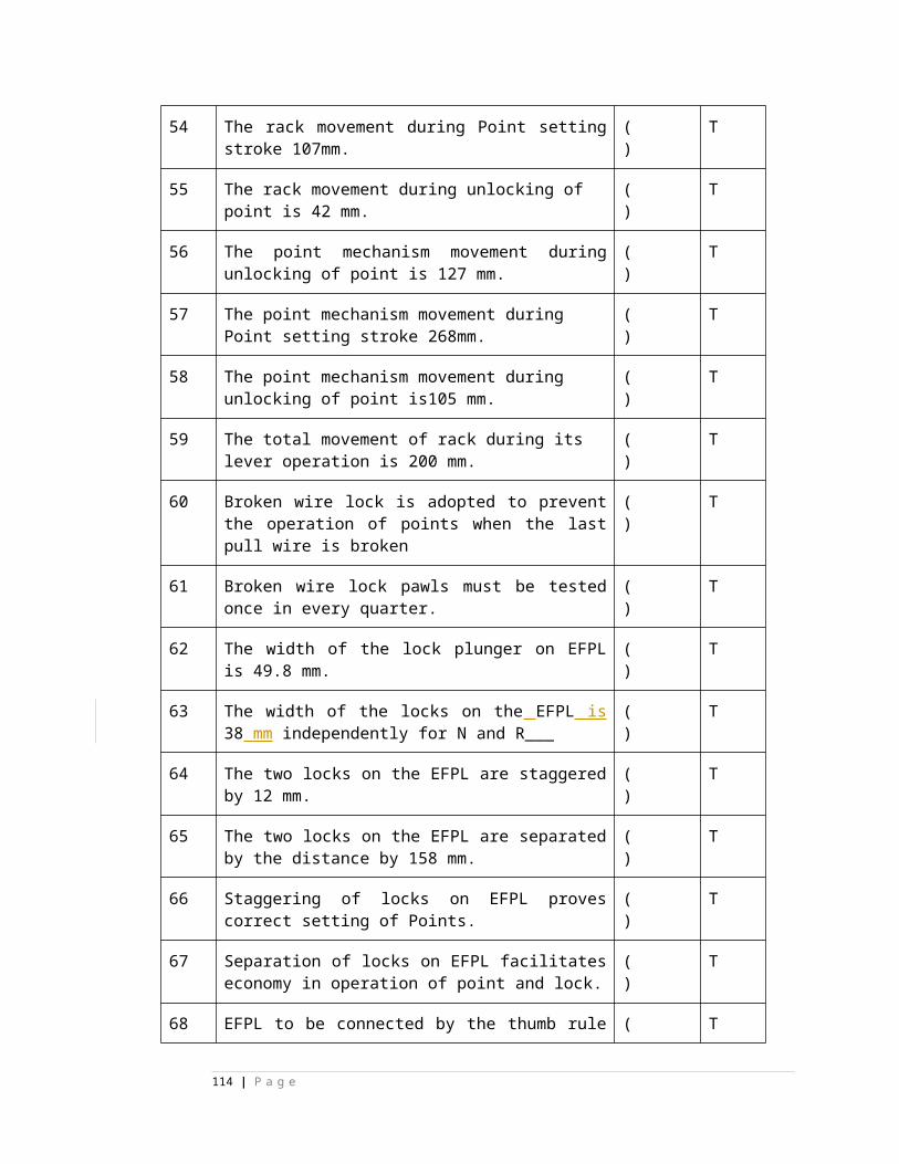
3 The signal lamps are triple pin lamp to avoid---------------- a) Lamp theft b) out of focus after replacement of lamp c) use for domestic purposed) loose grip
( ) b) out of focus after replacement of lamp
4 The no load current of signal transformer shall not be more than ------------------- a) 5 mAmp b) 15 Amp c) 40 mAmp d) 15 mAmp
( ) d) 15 mAmp
5 The rating of SL 35 B signal lamp is-----------------------.a) 12 volts 24 watts & 12 volts 16 watts b) 12 volts 33 watts & 12 volts 33 watts c) 12 volts 24 watts & 12 volts 24 watts d) 12 volts 16 watts & 12 volts 16 watts
( ) b) 12 volts 33 watts & 12 volts 33 watts
6 The power ratting of signal transformer is ------------------- a) 400VA b) 40VAc) 4KVA d) 40KVA
( ) b) 40VA
7 The tapping on secondary side of signal transformer is/are ------------------- a) 13 volt b) 14.5 volt c) 16 volt d) a,b &c
( ) d) a,b &c
8 When MECR & Signal transformer are placed in side two aspect unit then number of cable conductors required in tail cable (with double cutting) are---------------------- a) 10 b) 8 c) 12 d) 6
( ) b) 8
Match the Following :
1. SL-5 (e ) a) triple pole ON aspect
2. SL –18 (d ) b) triple pole OFF aspect
3. SL – 21 (c ) c) double pole ON aspect
4. SL – 35 A (b ) d) cascaded OFF aspect
5. SL – 35 B (a ) e) indication Lamp
Match the Following :
1. colour inner lens (e ) a) 140mm yellow
2. Clear outer lens (d ) b) no lens
3. Route indicator lens (c ) c) 92mm
114 | P a g e
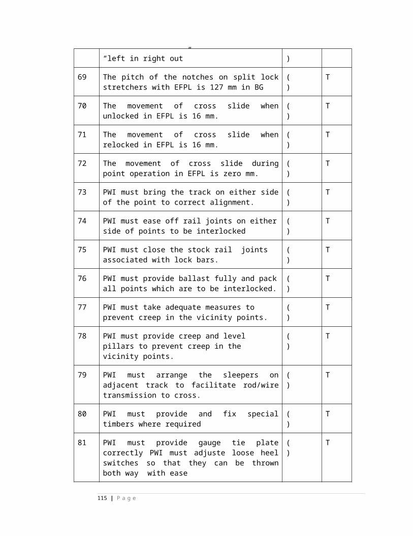
4. LED signal (b ) d) 213mm
5. Calling ON (a ) e) 140mm
State True or False1 The 3 pins of CLS lamp are provided to prevent
lamp theft (True/False)
( ) False
2 LED signal works on 110 volts AC only. (True/False)
( ) False
3 All type ECR can be used with LED signal (True/False)
( ) False
1 When Distant in double distant territory displays proceed aspect then indicates -----------------a) Run through on main line b) run through on loop line c) Train going to be received on main line b.d) a&c
( ) d) a&c
2 When inner Distant in double distant territory displays proceed aspect then indicates ----------------a) Run through on main line b) run through on loop line c) Train going to be received on main line band.d) a&b
( ) a) Run through on main line
3 When Distant in double distant territory displays proceed aspect then indicates -----------------a) Run through on main line b) run through on loop line c) Train going to be received on main line b.d) a&c
( ) d) a&c
4 When inner Distant in double distant territory displays proceed aspect then indicates ----------------a) Run through on main line b) run through on loop line c) Train going to be received on main line band.d) a&b
( ) a) Run through on main line
1 1SL 18 lamp and SL 35 A lamp can not used in cascaded off aspect. (True/False)
( ) False
2 LED signal unit and SL 35 A lamp can not used in cascaded off aspect. (True/False)
( ) False
3 Siemens ON ECR can be used in aspect control circuit with LED signal.
( ) False
115 | P a g e
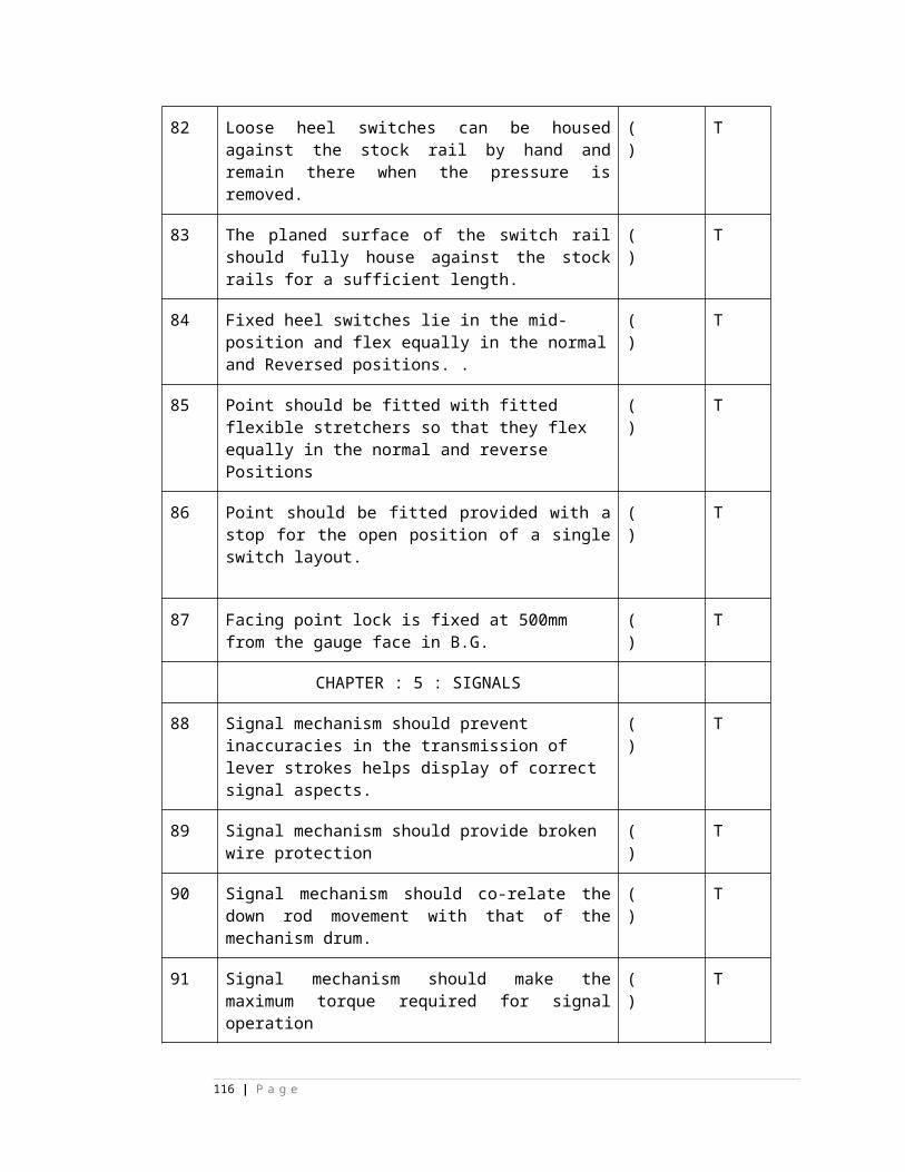
(True/False) 4 No load current of signal transformer shall not be more
than 15 Milli Amps.(True/False)
( ) True
5 Normally No load current of signal transformer shall be measured on secondary side of transform.(True/False)
( ) False
6 Terminal voltage of signal lamp shall not be more than 90% of ratted voltage of lamp.(True/False)
( ) True
7 Purpose cascading is to protect blank signal and red lamp protection is prevent blanking of signal respectively (True/False)
( ) False
8 Purpose red lamp protection is prevent blanking of signal in case of OFF aspect lamp fuses.(True/False)
( ) False
9 One aspect of CLS unit contains two lenses, inner clear lens and outer colour lens. (True/False)
( ) False
10 Auxiliary filament of triple pole lamp will also burn while main filament is burning.(True/False)
( ) False
11 Proceed aspect of Distant Signal in single distant territory indicate run-through condition always.(True/False)
( ) False
12 The Distant Signal in double distant territory has total three aspects.(True/False)
( ) False
13 Home signal is always a slotted signal.(True/False)
( ) False
. S.No….n Question( ) Ans
wer
1.Track locking is made effective A&E positions on point lever.(True/False)
2.Dead Approach to be provided where the sufficient length of Approach Track circuit cannot be provided.(True/False)
3.Indication locking is to be provided where there is no rigid connection between the lever and its function. (True/False)
4.The back locking on a signal lever will be effective at B position.(True/False)
5.The purpose of UYR1 and UYR2 circuits is to release the after the train is received signals. (True/False)
116 | P a g e
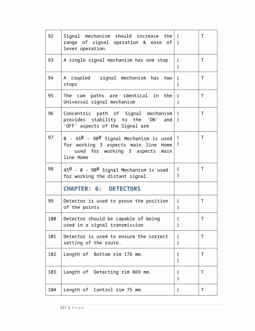
6.The purpose of ‘NA’ band contact across HR relay is to achieve cross protection to HR relay . (True/False)
7.The purpose of GECR contact in HR circuit is to avoid the bobbing of the signal when the signal ahead is changing its aspects. (True/False)
8.The purpose of JR back contact in HR circuit is to cancellation is not in progress when the signal is being initiated.(True/False)
9.To perform the function of lock bar, in power signaling track circuit & lever lock ll be provided.(True/False)
10.When a stop signal is taken off, the crank handle must be in locked condition.(True/False)
11.In junction type route indicator, the maximum number of routes can be displayed is seven . (True/False)
12.In junction type route indicator, to energize UECR minimum three
nos. of route lamps must be in lit condition.(True/False)
13.The maximum number of routes which can be indicated by using stencil type route indicator is four.(True/False)
14.Approach locking is provided for the goods loop starter.(True/False)
15.
Indication locking on signals will be effective at B position of signal lever. (True/False)
16.The berthing track circuit shall be proved in HR circuit of shuntsignal.(True/False)
17.
The approach locking is provided to prevent manipulation of the route when train cross the signal. (True/False)
18.All the track circuit in the route shall be proved in the back locking.(True/False)
19. Indication locking on signal lever is effective on ‘B’ &’D’ position. (True/False) ( ) ( F )
20.TSR circuit achieves one signal one-train principle.(True/False)
( ) ( T )
21.Point in isolation must be proved in shunt signal control.(True/False)
( )( T )
22.Track locking performs the function of lock bar.(True/False)
( )( T )
23. UYR relays provided to prevent premature route release. ( )( T )
117 | P a g e
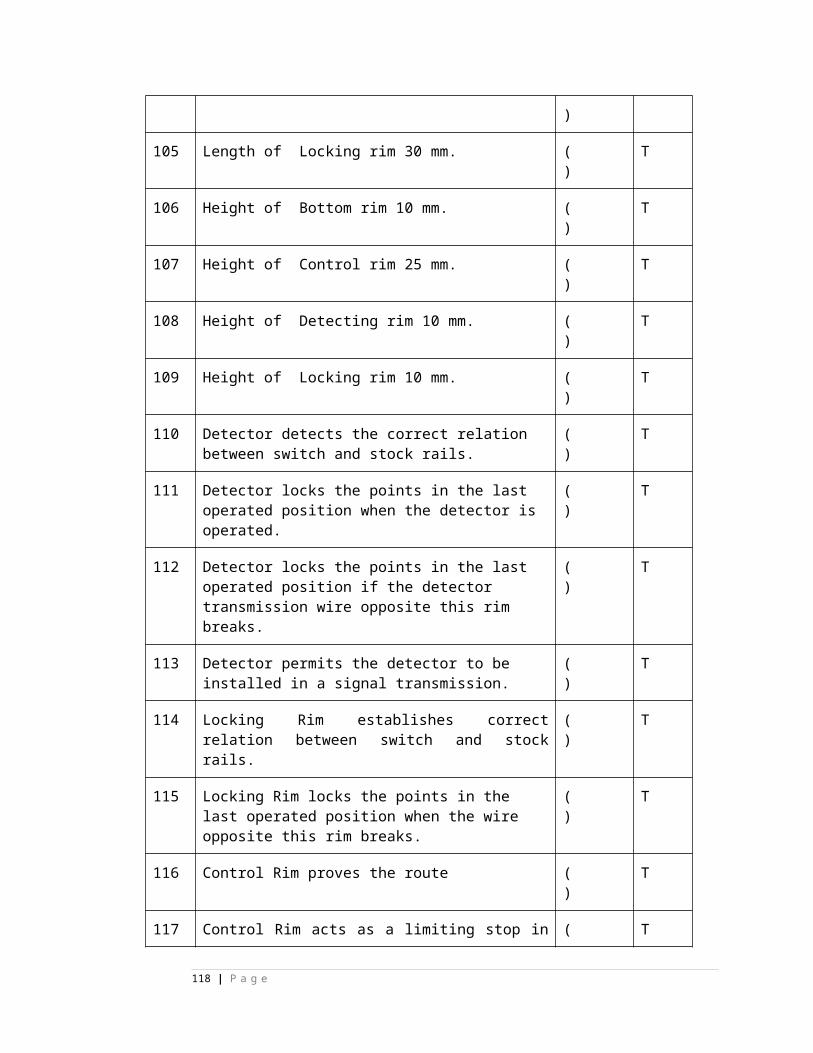
(True/False)
Chapter-1
1.In home signal HR circuit points in the route must be proved(True/False)
2.In home signal HR circuit points in the over lap must be proved(True/False)
3.In home signal HR circuit points in the isolation must be proved(True/False)
4.In home signal HR circuit track circuit in the route must be proved(True/False)
5.In home signal HR circuit track circuit in the berthing portion must be proved(True/False)
6.In home signal HR circuit track circuit in the over lap must be proved(True/False)
7.In home signal HR circuit crank handle in and locked must be proved(True/False)
8.In home signal HR circuit route release relays dropped position must be proved (True/False)
9.In home signal HR circuit route cancellation relays dropped position must be proved(True/False)
10.In home signal HR circuit calling on signal below home signal not operated position must be proved(True/False)
11.In home signal HR circuit one signal one train feature must be proved(True/False)
12. In home signal HR circuit route lamps lit for diverging line must be proved
13.In home signal HR circuit route lamps not lit for straight line must beProved(True/False)
14.In home signal HR circuit LC gate closed and locked condition mustbe proved(True/False)
15.In home signal HR circuit siding control normal position must beproved(True/False)
16.In home signal HR circuit its control operated position in both positive and negative limbs must be proved(True/False)
17.In home signal HR circuit cross protection across HR must be proved(True/False)
118 | P a g e
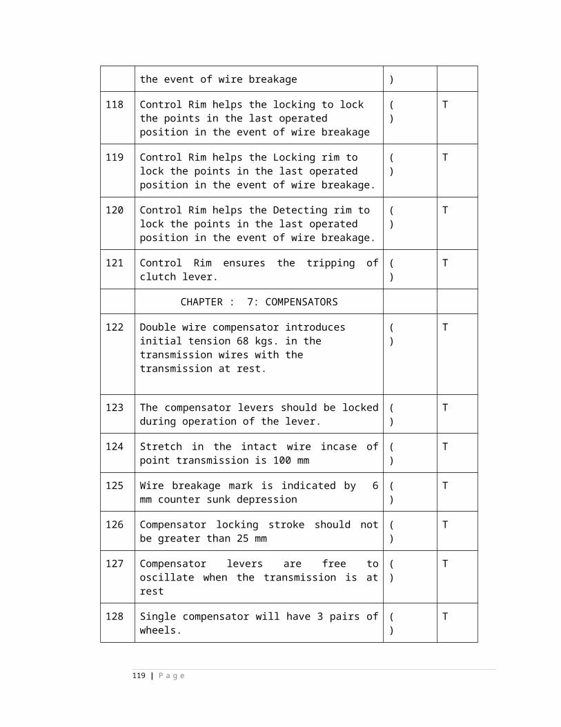
S12 chapter 3.
1. To ensure the signal ahead is not blank in the HR circuit of home, only Main line starter HECR & DECR in parallel are proved.
( ) False
2. The points in isolation must be proved in HR circuit of calling on signal.
( ) True
3. All tracks in the route overlap and berthing shall be proved in home signal HR.
( ) True
4. For shunt signal, the route locking is up to berthing track included.
( ) False
5. For approach locking of loop line starter, the berthing track alone is proved.
( ) True
6. Calling signal detects all the points, which the main signal above it detects excluding the overlap points.
( ) True
7. Generally Dead Approach locking is provided for a home signal of wayside station.
( ) True
8. The CO signal will have that many numbers of routes as many overlaps available.
( ) False
9. The CO signal locks the starter ahead and vice versa.
( ) True
10. The shunt signal signal is provided with approach locking.
( ) True
11. In panel interlocking, the CO signal cancellation period is 240 seconds.
True12. ( ) True
119 | P a g e
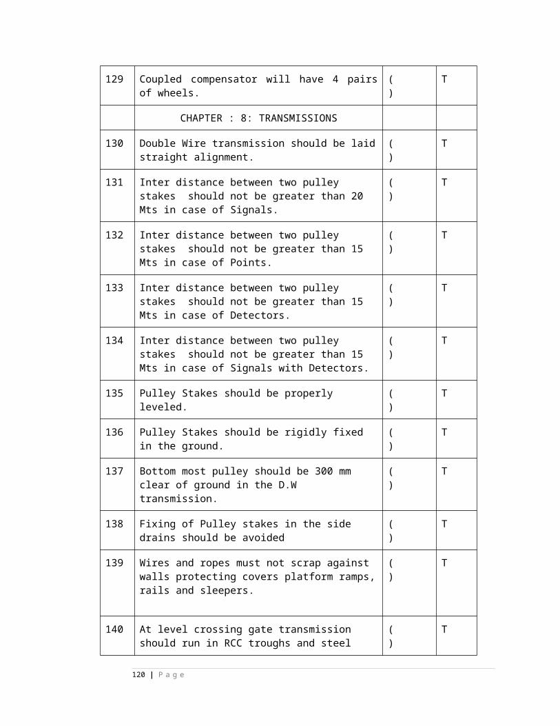
13. . In panel interlocking, all signals except CO signal will have cancellation period of 120 seconds.
( )
14. In panel interlocking for way side stations, the starter signal is provided with cancellation period of 240 seconds.
( )
chapter no.3- Key
1. False2. True 3. True 4. False5. True 6. True 7. True 8. False9. True10.True11.True12.True
S-12 chapter no.4
State true or false
1. It shall not be possible to insert the crank handle extracted from one group of points in the point machine of any other group of points.
( ) True
2. For cross protection of HR relay, UCR front contact is used.
( ) False
3. On complete arrival of the train, SM normalized the signal knob but route not released due to one of the back lock track failed, but SM reversed the gate control knob and slot was sent to gate lodge with a time delay 120 seconds to open the gate
( ) True
120 | P a g e
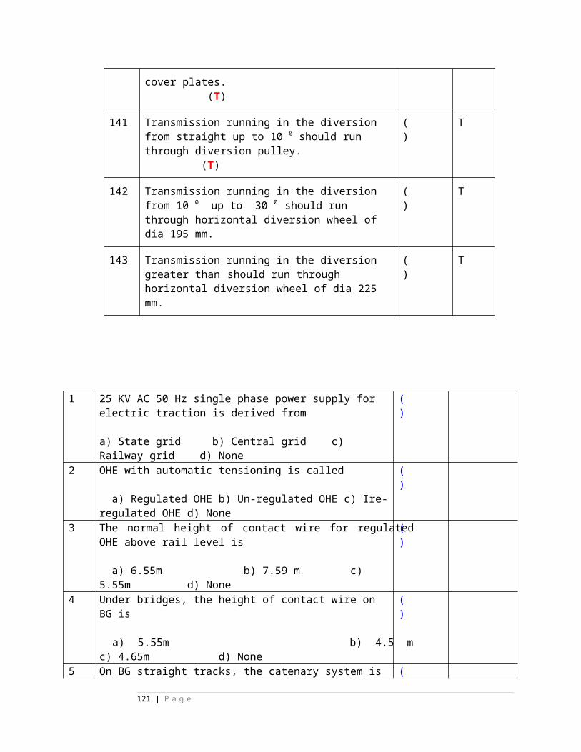
4. For home signal DR to pick up, it is sufficient that main line starter DR is in pick up condition.
( ) False
5. When economizer pushbutton is pressed to extract the crank handle, the lock coil is energized only after dropping of CHLR.
( ) True
6. When SM’s key is taken out, still it is possible to take off a signal from the panel.
( ) False
7. In route setting type interlocking, when signal knob is reversed, the route setting relay LR is energized to operate points to required position.
( ) False
8. In RRI, point knob has to be kept in ‘C’ position, for automatic operation of points.
( ) True
9. In route setting panel interlocking with domino type panel with all buttons, two common point group buttons are provided i.e. one for normal and other for reverse
( ) True
10. OVSR relay picks up automatically when run through signals are given and train cleared berthing track.
( ) True
11. LC gate opening is possible without any time delay, after complete arrival of train but route not released.
( ) False
12. In all buttons route setting type panel, the NNR drops the moment NRR picks up
( ) True
13. One signal one train movement is achieved through TSR circuit
( ) True
14. When SM locks the panel, RR dropping is prevented by SMCR front contact bridging the knob reverse contact.
( ) False
15. When signal is taken off the CHFR relay drops , thereby Crank handle is locked in the EKT can not be taken out.
( ) True
16. In ASR circuit indication, back & approach locking were proved.
( ) True
17. For cancellation of a signal, JSLR picks up through its own ASR drop contact only after the signal knob is normalized.
( ) True
18. The track locking is proved in WLR circuit of a point.
( ) True
121 | P a g e
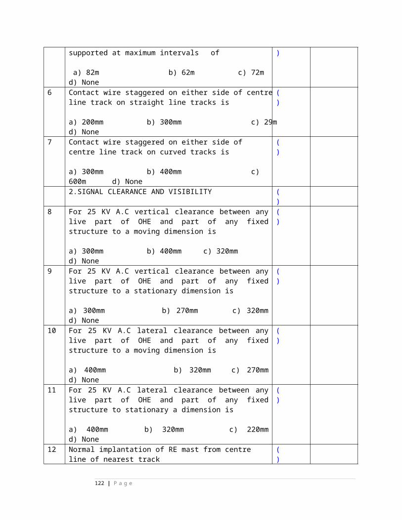
19. With the help of one front contact maximum three repeater relays can be energized
( ) True
20. OVSR relay picks immediately when the train clears the back lock tracks , occupies berthing track and stops at the foot of the starter.
( ) False
21. UYRs are made slow to release because ASR picks up through UYRs up and UYRs pick up through ASR back contact.
( ) True
22. UCR front contact is proved in ASR so that ASR drops the moment route checking is completed.
( ) False
23. When the train arrives on the berthing track and stops at the foot of the starter, the overlap cancellation takes place automatically and OVSR picks up after 2 minutes time delay.
( ) True
24. The calling signal locks the main signal above it. ( ) True25. when the signal is in taken off condition, if the SM
turns LC gate controlling knob to reverse, then the gate man can extract the LC gate key for the opening the gate.
( ) False
26. In route setting panel interlocking, NNR picks up through the back contact of NRR, the moment ALSR picks up.
( ) True
27. When the ASR (proved in point WLR cct) drops, the WLR still can pick up and point can be operated.
( ) False
28. 28. The GECR relay remains in pickup when any one of the aspects is burning in the signal.
( ) True
Chapter 4-KEY
1. True2. False3. True4. False5. True6. False7. False8. True9. True10. True11. False12. True13. True14. False
122 | P a g e
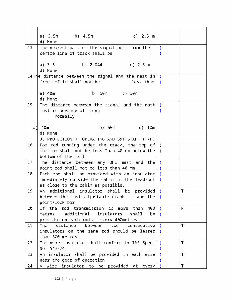
15. True16. True17. True18. True19. True20. False21. True22. False23. True24. True25. False26. True27. False28. True
Chapter no.1STATE TRUE OR FALSE
1. Conflicting signal-to-signal locking is proved in at least two stages.
( )
True
2. In relay interlocking, the interlocking is checked at UCR, ASR & HR stages.
( )
False
3. The two types of relay interlocking are Non route setting type and Route setting type.
( )
True
4. The two types of relay interlocking are panel interlocking and RRI
( )
True
5. The two types of interlocking are Non route setting type interlocking & panel interlocking.
( )
False
6. The two types of interlocking are route
( )
False
123 | P a g e
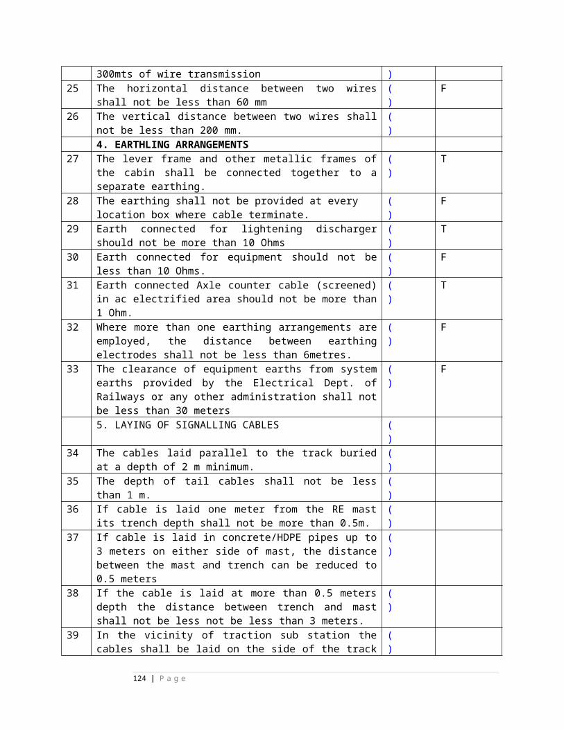
setting type interlocking and RRI
7. Track indications on the panel when track is clear and route set and locked is white strip lights.
( )
True
8. Track indication on the panel when track is occupied or failed is red
( )
True
9. Track indications on the panel when the track is clear and route set locked is yellow strip lights (LEDs)
( )
False
10.
Track indications on the panel when the track is clear and route set & locked is green strip lights (LEDs)
( )
False
11.
when no route is set and no track failed the indications on the panel for tracks is blank.
( )
True
Chapter no.1 key
1. True2. False
124 | P a g e
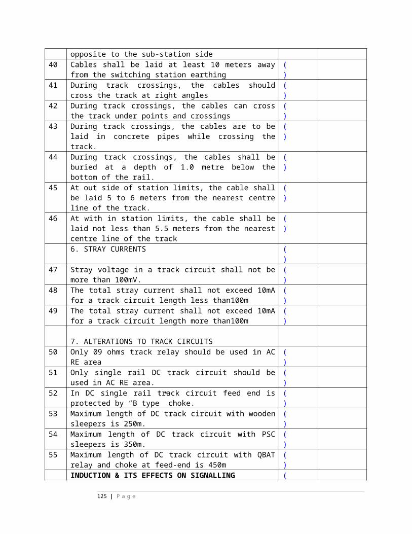
3. True4. True5. False6. False7. True8. True9. False10. False11. True
S-12 CHAPTER 2
STATE TRUE OR FALSE
1. Point knobs used in RRI are of 3 position type.
( ) True
2. In route setting type inter locking points are to be operated to correct position before signal is taken off.
( ) False
3. Non route setting type / panel interlocking the points are to be operated manually before clearing the signal.
( ) True
4. When UCR picks up , ASR concerned will be dropped either in PI or in RRI.
( ) True
5. The points will be set automatically in RRI when signal button and route button are pressed simultaneously.
( ) True
6. In panel interlocking LR relay sets all the relevant points to the correct position automatically.
( ) False
7. The point switches used in route setting type inter locking will have three positions i.e. N, C and R.
( ) True
125 | P a g e
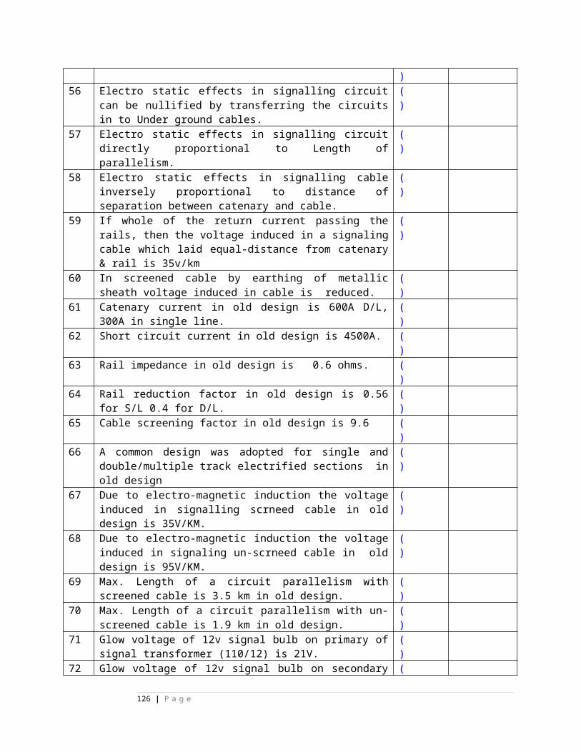
8. For automatic operation of points in RRI , the point knob has to be set to centre ( C ) position.
( ) True
9. When the point switch 3 positions is kept in the centre( C) position then both NC & RC switch contacts are made to facilitate automatic point operation.
( ) True
Chapter 2 Key1.True2.False3. True4. True5. True6. False7. True8. True9. True
S-15,16
Siemens question banks
Select the choice
1. For initiation of signal ------- letter is used in Siemens concept A) Z B) Z1 C) Z2 D) none
( ) A) Z
126 | P a g e
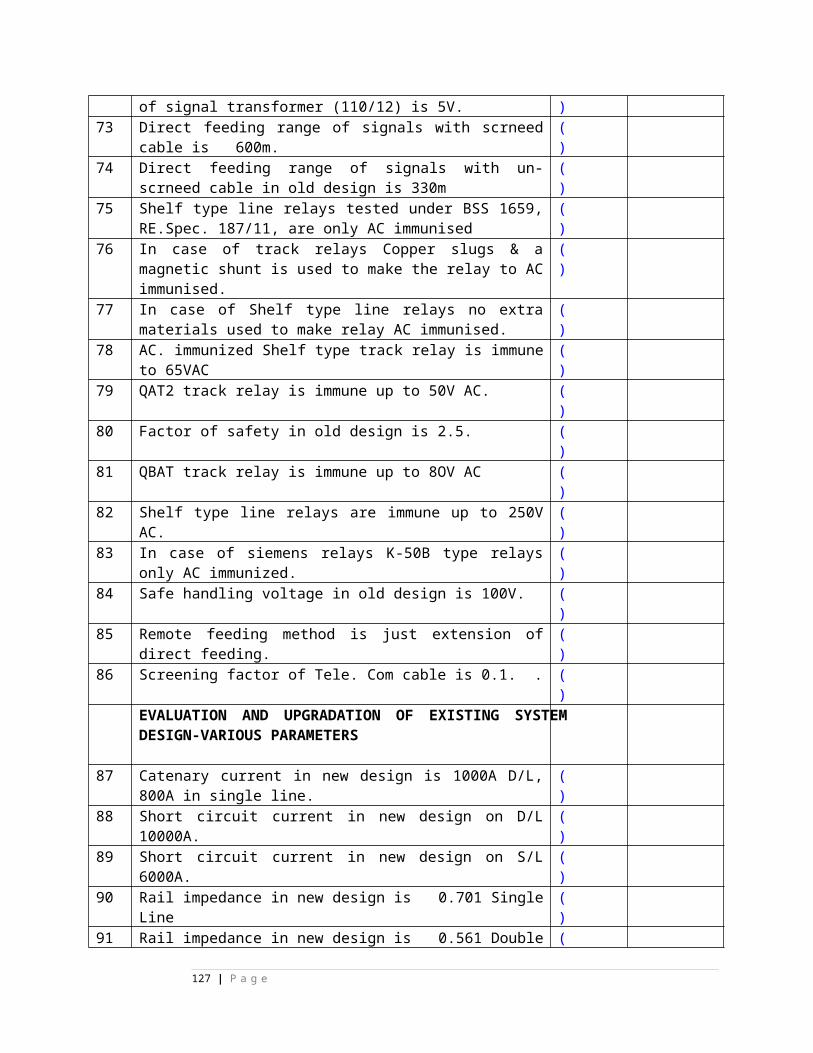
2. For overlap setting relay the -------letter is used in Siemens concept A) Z 2 B) U C) R D) none
( ) A) Z 2
3. For straight line route section the--- letter is used in Siemens concept A) Z 2 B) U C) R D) none
( ) D) none
4. for first diversion route section the ----- letter is used in Siemens concept A) Z 2 B) U C) B D) none
( ) C) B
5. For second diversion route section the ----- letter is used in Siemens concept A) D B) C C) B D) A
( ) B) C
6. For any BUTTON the ----- letter is used in Siemens concept A) U B) G C) N D) W
( ) C) N
7. For any signal button relay the ----- letters are used in Siemens concept A) GN B) GNR C) NR D) SR
( ) A) GN
8. For common point button the ----- letters are used in Siemens concept A) WWN B) WWWN C) W NR D) WWNR
( ) A) WWN
9. For emergency point button the ----- letters are used in Siemens concept A) EWN B) WWWN C) W NR D) WWNR
( ) A) EWN
10. For emergency point button relay the ----- letters are used in Siemens concept A) EWN B) WWWNR C) EW NR D) WWNR
( ) C)EWNR
11. UNR means -------------- A) route button relay B) route checking relay C) route locking relay D) under normal relay E) none
( ) A) route button relay
127 | P a g e
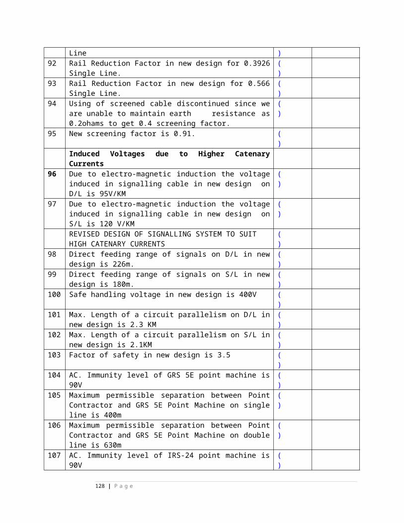
12. GNCR means------------------- A) Signal button relay B) signal button checking relay C) signal Checking relay D) gate normal checking relay E) none
( )
13. UNCR means-------- A) Route button relay B) route checking relay C) route locking relay D) Route button checking relay E) none
( ) D) Route button checking relay
14. WNCR means ---------- A) Point button relay B) point checking relay C) point locking rela D) Point button checking relay E) none
( ) D) Point button checking relay
15. UECR means --------- A) Route button relay B) route checking relay C) lamp checking relay D) Route lamp checking relay E) none
( ) D) Route lamp checking relay
16. EUUYN cancellation is registered by --------- counter A) EUYZ B) BUUYZ C) EUUYZ D) EUYYZ
( ) C) EUUYZ
17. Key is provided for ---------button. A) EUYZ B) EUYYN C) EUYN D) EWNZ
( ) C) EUYN
18. Seal arrangement is provided for ---------- A) EUYZ &EWN B) EUUYN &EWN C) EUYN &EWN D) None
( ) C) EUYN &EWN
19. Written memo by on duty SM/ASM to S&T staff is compulsory before operation of --------- A) GN B) EUUYN C) EUYN D) UN
( ) C) EUYN
20. In new installation EUYN key is provided ----------- A) On top of panel B) on left side C) on right side D) inside panel desk E) In relay room
( ) D) inside panel desk
128 | P a g e
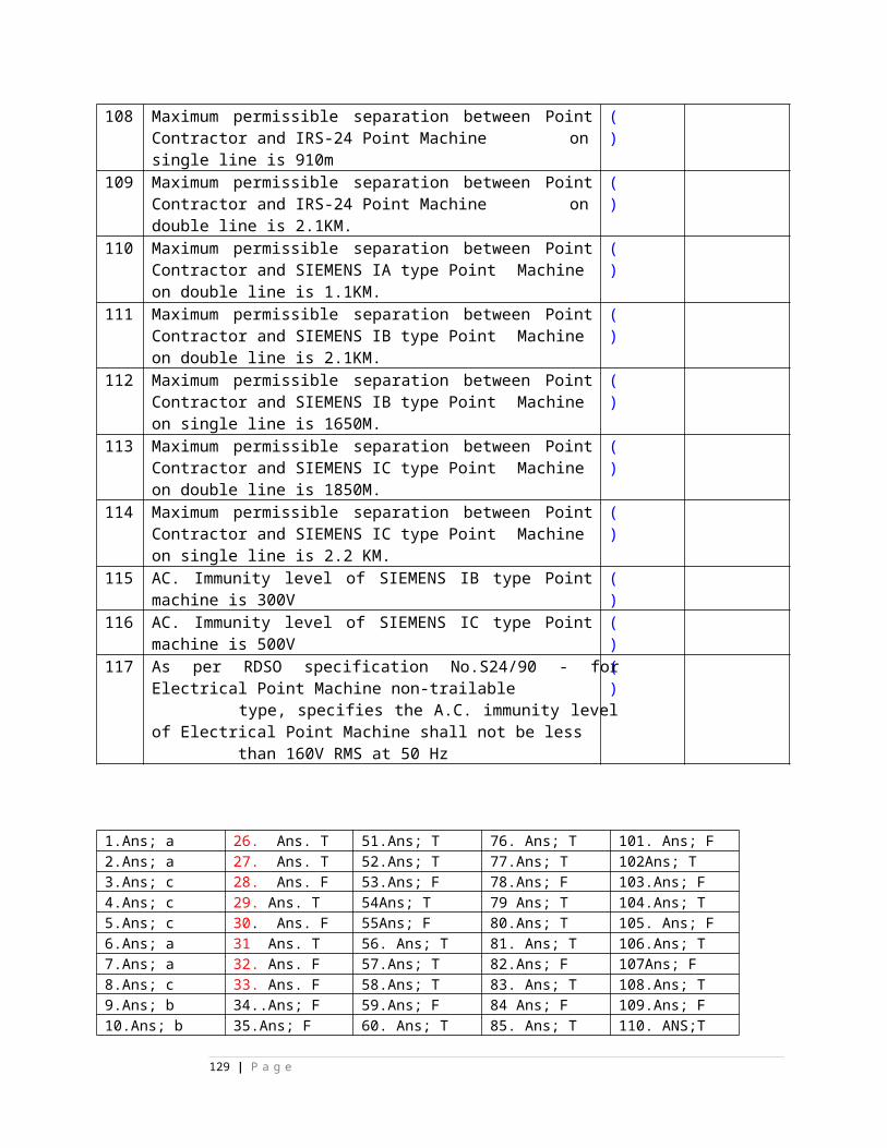
21. EWN operation can be done when ----------------- A) Route is not set, pt TPR’s up B) route is set, pt TPR’sup C) Route is set, pt TPR’s down D) route is not set,TPR’s down E) None
( ) D) route is not set, pt TPR’s down
22. WWN operation is possible when route is not set & TPR’s are down. State true/false A) May be false B) true C) false D) cannot declare E) none
( ) C) false
23. EWN & WWN simultaneous command is possible at a time. A) May be false B) false C) true D) cannot declare E) none
( ) B) false
24. WN & EWN simultaneous command is possible at a time when route is not set & TPR’s are down. A) May be false B) false C) true D) can not declare E) none
( ) C) true
25. WWN & WN simultaneous command is possible at a time when route is not set & TPR’s are down. A) May be false B) false C) true D) cannot declare E) none
( ) B) false
26 Two GN buttons operation simultaneously is possible because SM key is not Proved A) May be false B) false C) true D) cannot declare E) none
( ) C) true
27. GNR can be picking up by making SM key out A) May be true B) false C) true D) cannot declare E) none
( )
28 GNPR can not pick when SM key is out A) May be true B) false C) true D) cannot declare E) none
( ) B) false
29 GNR can not pick when SM key is out. A) May be true B) false C) true D) cannot declare E) none
( ) B) false
30. UNR can pick when SM key is out. A) May be true B) false C) true D) cannot declare E) none
( ) B) false
129 | P a g e
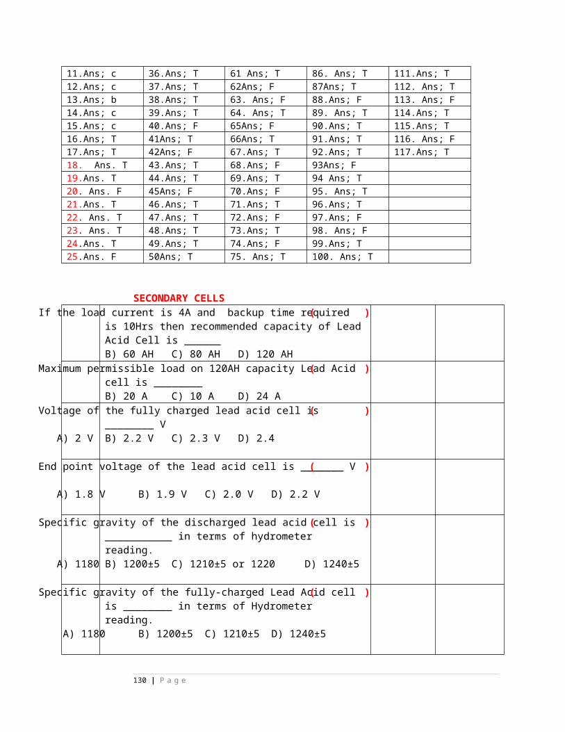
31. -------- GNCR is/are provided for one lay out. A) one B) two C) three D) four E) none
( ) A) one
32. -------- UNCR is/are provided for one lay out. A) one B) two C) three D) four E) none
( ) A) one
33 -------- MnGNPR is/are provided for one lay out . A) one B) two C) three D) four E) none
( ) A) one
34 -------- ShGNPR is/are provided for one lay out . A) one B) two C) three D) four E) none
( ) A) one
35 -------- MnGzR is/are provided for one lay out . A) one B) two C) three D) four E) none
( ) A) one
36 -------- ShGzR is/are provided for one lay out . A) one B) two C) three D) four E) none
( ) A) one
37 -------- ZDUCR is/are provided for one lay out . A) one B) two C) three D) four E) none
( ) A) one
38 Z1UR is provided for each ------------------ A) berthing potion B) route section C) subroute D) signal group E) Route group
( )
39 GNPR is provided for each ------------------ A) Route group B) route section C) subroute D) signal group E) none
( ) E) none
40 UNPR is provided for each ------------------ A) berthing potion B) route section C) subroute D) signal group E) None
( ) E) none
41 GNCR works for------------------- A) main signal button B)shunt signal button C) main and shunt sign D)route sections E) none
( ) C) main and shunt signal buttons
130 | P a g e
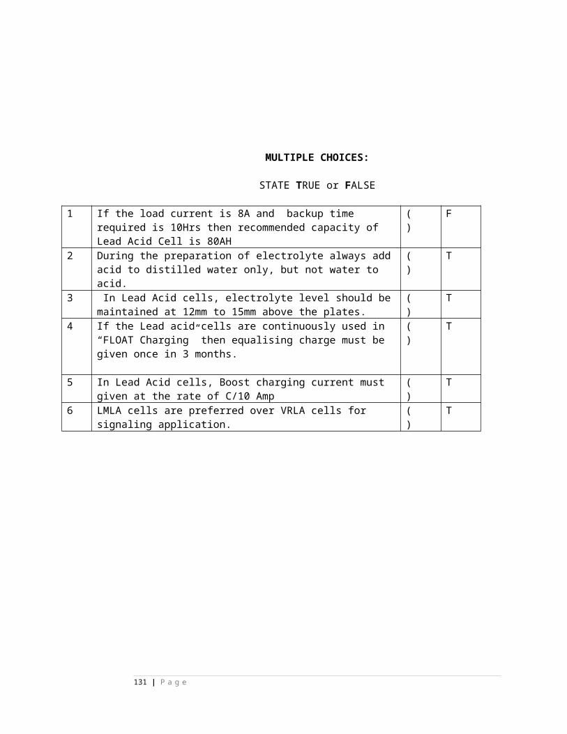
42 UNCR works for------------------- A) main signals B)shunt signals C) main and shunt signals D)route sections E) none
( ) E) none
43 GNCR drops when ------------------ is pressed. A) UN B) BN C) GN D) WN E) None
( ) C) GN
44 UNCR drops when ------------------ is pressed. A) UN B) BN C) GN D) WN E) None
( ) A) UN
45 WNCR drops when ------------------ is pressed. A) UN B) BN C) GN D) WN E) None
( ) D) WN
46 MnGNPR drops when ------------------ is pressed. A) UN B) BN C) GN D) WN E) None
( ) C) GN
47 MnGZR picks up when ------------------ is pressed. A) GN B) GN+UN C) GN +WN D) WN +WWN E) None
( ) B) GN+UN
48 ZDUCR picks up when ------------------ is pressed. A) GN B) GN+UN C) GN +WN D) WN +WWN E) None
( ) B) GN+UN
49 Z1UR picks up when ------------------ is pressed. A) GN B) GN+UN C) GN +WN D) WN +WWN E) None
( ) B) GN+UN
50 Energization of MnGZR proves ------------------------------ A) main point is initiated B) only main signal is initiated C) main and shunt signal are initiated D) main or shunt signal is initiated E) only shunt signal is initiated
( ) B) only main signal is initiated
51 Energization of ShGZR proves ------------------------------ A) main point is initiated B) only main signal is initiated C) main and shunt signal are initiated D) main or shunt signal is initiated E) only shunt signal is initiated
( ) E) only shunt signal is initiated
52 Energization of ZDUCR proves ---------------------- A) main point is initiated B) only main signal is initiated C) main and shunt signal are initiated D) main or shunt signal is initiated E) only shunt signal is initiated
( ) D) main or shunt signal is initiated
131 | P a g e
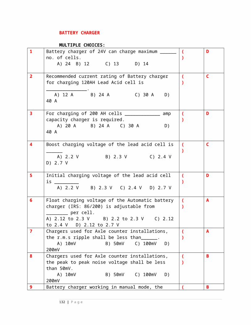
53 direction relay is named as per --------------------------- A) top point B) point track C) berthing track ckt D) signal E) none
( ) C) berthing track ckt
54 Z1UR is named asper ------------------- A) top point/ B) subroute name C) berthing track ckt D) route section E) none
( ) B) subroute name
55 sub route is named asper -------------------- A) Z1UR B) Top point C) signal number D) Top point or signal number E) track ckt
( ) D) Top point or signal number
56 route section is named as per ----------------A) top point B) subroute name C) berthing track ckt D) signal E) none
( ) B) subroute name
57 WN+WWN operation leads to -------------- when point zone TPR’s are up A) point operation B) TPR’s up C) EWNR to pick up D)TPR’s to drop E) none
( ) A) point operation
58 WN+EWN operation leads to ------------- when point zone TPR’s are drop A) point operation B) TPR’s up C) WWNR to pick up D)TPR’s to drop E) none
( ) A) point operation
59 WWN+EWN operation leads to ------------- when point zone TPR’s are drop A) point operation B) TPR’s up C) WWNR to pick up D)TPR’s to drop E) none
( ) E) none
60 UN+GN operation leads to ------------- A) signal clearance B) TPR’s up C) WWNR to pick up D)TPR’s to drop E) none
( ) A) signal clearance
132 | P a g e
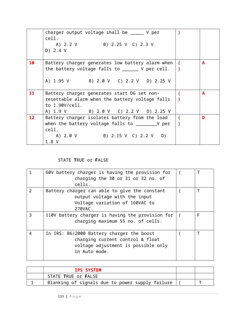
Siemens relays1 Siemens relays other name is -------------
A) k-50 B) k-60 C) k-59 D) k-69 E) none
( )
A) k-50
2 Siemens relays specification is A) IRS S46-76 B) IRS S47-76 C) IRS S46-77 D) IRS S76-46 E) None
( )
A) IRS S46-76
3 Siemens relays are ------------------------- typeA) Dependant B) independent C) separate D) twin E) none
( )
B) indepe
133 | P a g e
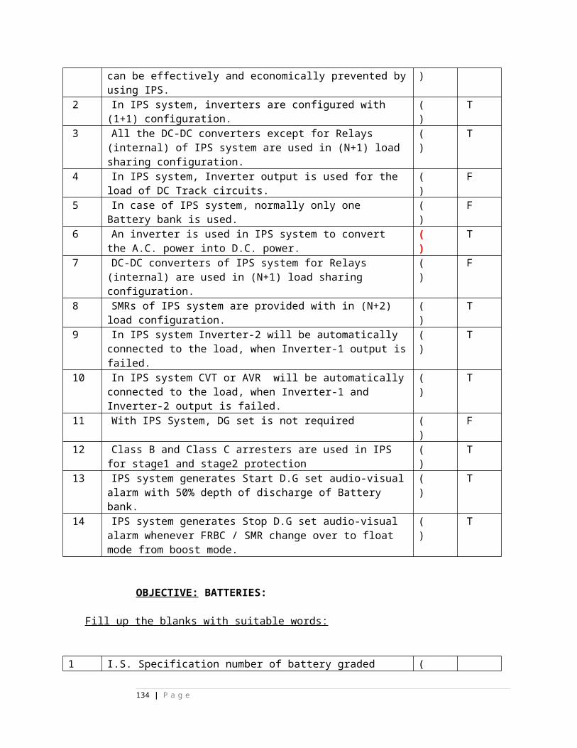
ndent
4 Siemens relays are --------------------- typ A) double make double break B)spring C)contact D) welding E)none
( )
A) double make double break
5 In Siemens relays there is no---------------------------contact A) Front B) back C) arm D) metal E) none
( )
C) arm
6 in Siemens relays -----------pins are provided to prevent invert plugging
( )
D)
134 | P a g e
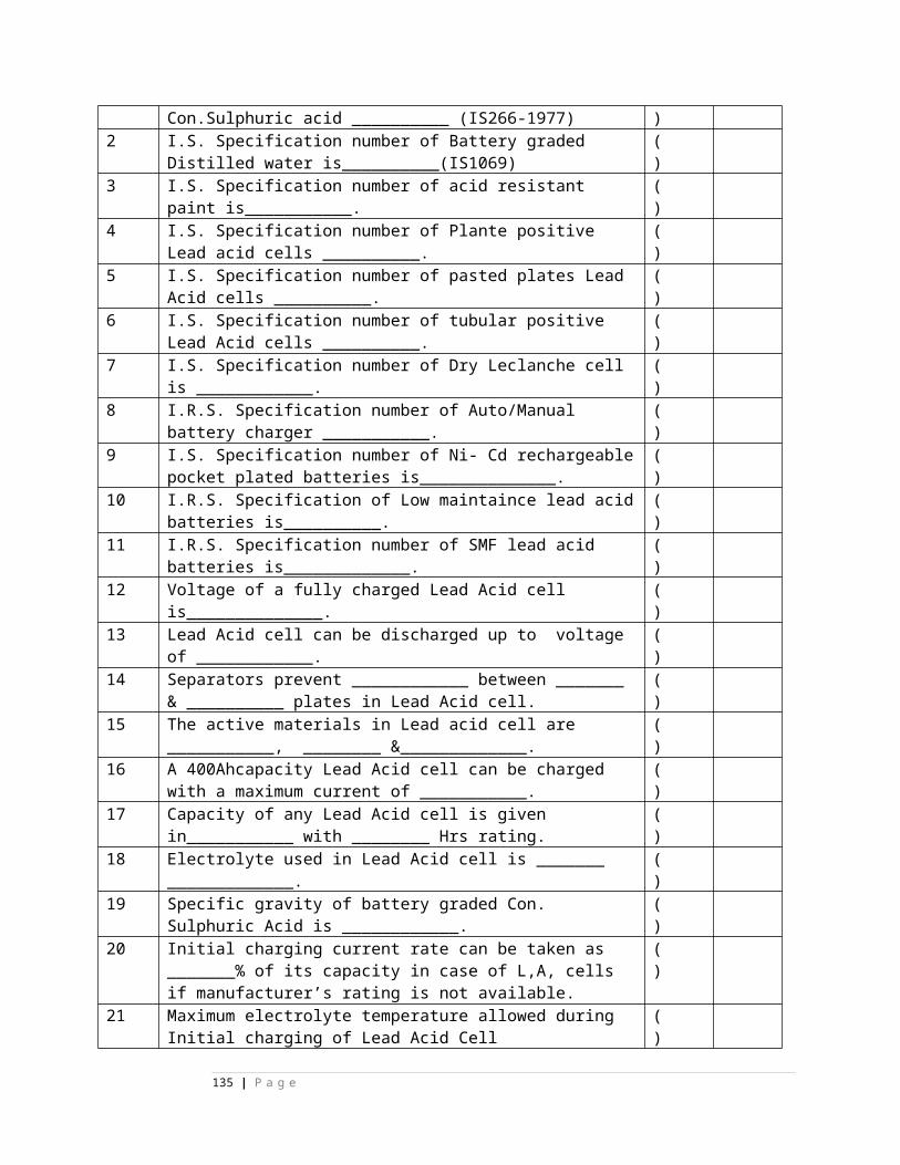
A) wide B)side C)hide D) guide E)none
guide
7 --------------- action in Siemens relays is self cleaning. A) Ripping B) fast C) slow D) wiping E) none
( )
D) wiping
8 Pick up time in Siemens relays is ------------------- A) 5ms B) 75-80ms C) 15-20ms D) 25-60ms E) none
( )
D) 25-60ms
9 Drop away time in Siemens relays is ------------------ A) 2-5ms B) 5-6ms C) 7-15ms D) 25-60ms E) none
( )
C) 7-15ms
10 In Siemens neutral type relays -------------combination is available A) 12f/4b B) 6f/2b C) 8f/8b D) 2f/6b E) none
( )
11 6f/2b,4f/4b combinations are available in Siemens -------------------A) ACI type B) ECR type C) clock type
( )
E)n
135 | P a g e
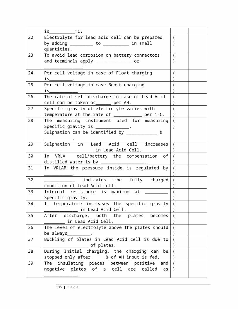
D) D type E)none one
12 In Siemens ACI type only -------- type is available A) 6f/2b B)5f/3b C) 4f/4b D)8f/8b E)none
( )
B)5f/3b
13 In interlocked Siemens relays -------------combinations art available A) 6f/2b B) 4f/4b C) 5f/3b D) all given in A, B, C option E) none
( )
D) all given in A, B, C option
14 In interlocked relay –---no contact is used as economizer contact A) 11 B) 12 C) 13 D) 14 E) none
( )
B) 12
15 In interlocked type ------------- arrangement is ( A
136 | P a g e
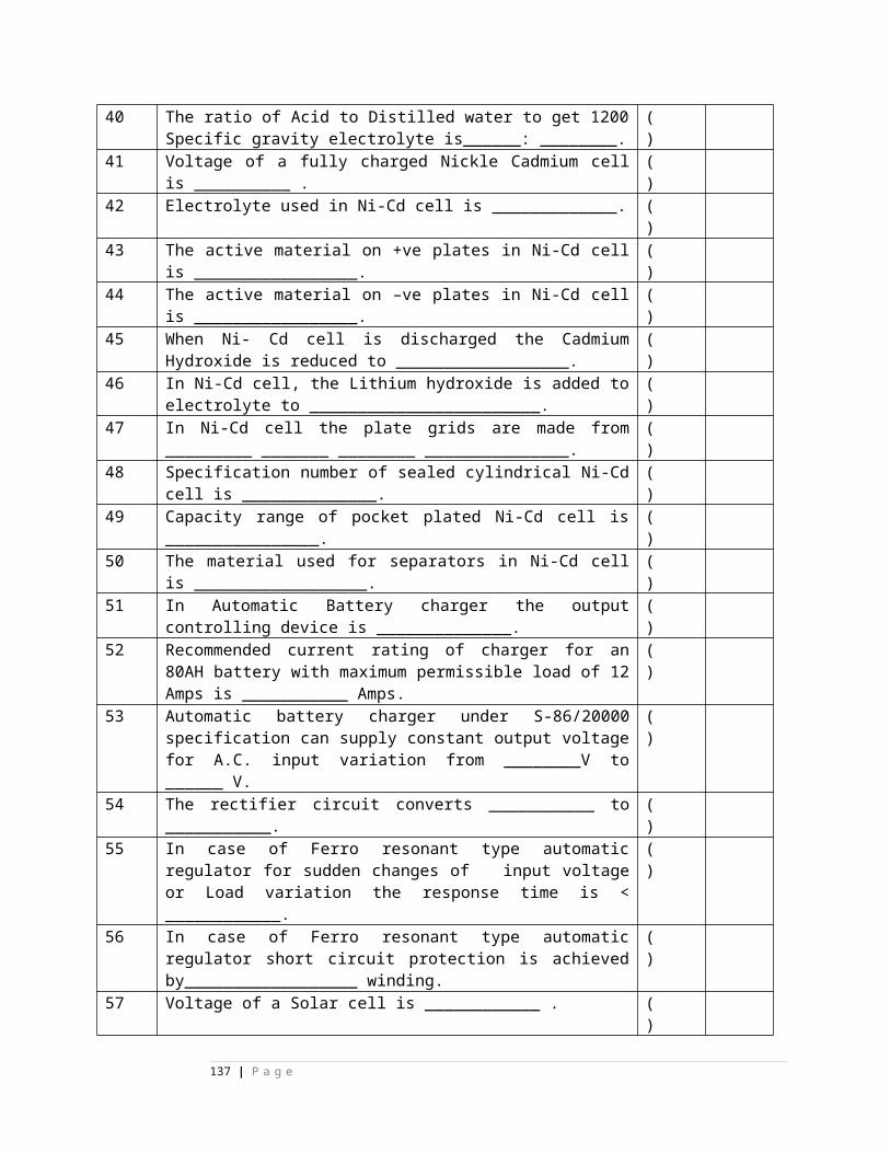
provided to keep relay in pick up condition A) Mechanical B) electrical C) electronic D) dynamic E) none
) ) Mechanical
16 Interlocked relay is used for -------------------- circuit. A) Conflicting B) series C) parallel D) indication E) none
( )
A) Conflicting
17 in interlocked type relays ------------coil is energized condition normally A) top B) side C) up D) bottom E) none
( )
A) top
18 In interlocked type relays ------------coil is de energized condition normally A) Normal B) side C) reverse D) bottom E) none
( )
C) reverse
137 | P a g e
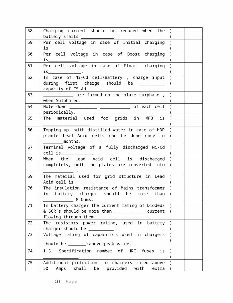
19 ON ECR is used for --------------aspect A) yellow B) green C) red D)white E)none
( )
C) red
20 OFF ECR is used for ----------------aspect. A) Yellow B) red C) blue D) on E) none
( )
A) Yellow
21 ON ECR contact combination is ------------- A) 6f/2b B)4f/4b C)5f/3b D)3f/3b E) none
( )
D)3f/3b
22 OFF ECR contact combination is ----- A) 6f/2b B) 4f/4b C) 5f/3b D) 3f/3b E) none
( )
D)3f/3b
23 UECR contact combination is ----- A) 6f/2b B) 4f/4b C) 5f/1b D) 3f/3b E) none
( )
C) 5f/1b
24 UECR is used for --------------aspectA) Yellow B) green C) red D) route E) none
( )
D) r
138 | P a g e
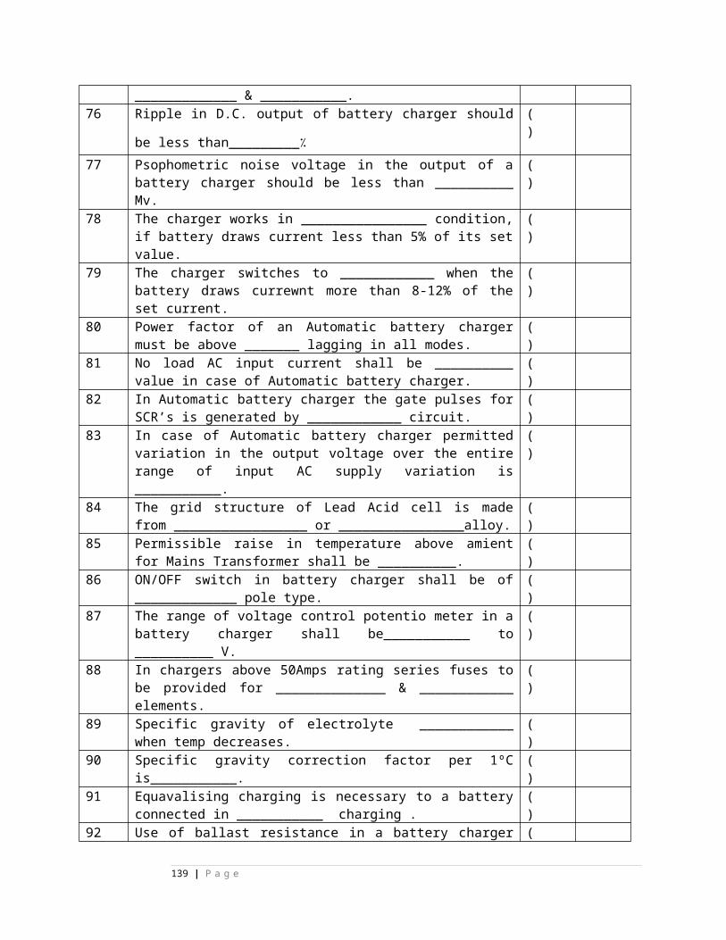
oute
25 -----------pin combination is provided in Siemens relays to prevent plugging of wrong relays A) guide B) non magnetic C) residual D)coding E) none
( )
D)coding
26 in 5f/3b contact combination ---is back contact A) 11 B) 12 C) 13 D)14 E)15
( )
E)15
27 in 5f/3b contact combination ---is back contact A) 1 B) 2 C) 3 D) 4 E)11
( )
D) 4
28 in 5f/3b contact combination ---is back contact A) 11 B) 12 C) 3 D)14 E)none
( )
E)none
29 in 6f/2b contact combination ---is back contact A) 11 B) 12 C) 13 D)14 E)15
( )
E)15
30 in 6f/2b contact combination ---is back contact A) 1 B) 2 C) 3 D) 4 E) 5
( )
E) 5
139 | P a g e
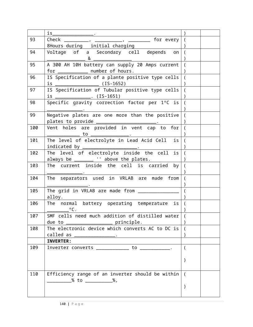
DOMINO AND CONTROLPANEL1 size of domino available in Siemens concept are
A)63mmx38mm B)83mmx68mm C) 45mmx34mm D) 54mmx38mm E) none
( )
A)63mmx38mm
2 compartments given in domino are --------- A) 11 B) 12 C) 13 D)14 E)15
( )
E)15
3 terminals provided in domino are -------A) 12 B)14 C)16 D)18 E) none
( )
4 -------- terminal carries neg of indication cktA) 3&8 B)8&13 C)16 D)15 E) none
( )
C)16
5 common aluminum plate is connected to terminal------- A) 3&8 B)8&13 C)16 D)15 E) none
( )
6 Arrangement of common aluminum plate is such that ----------------- Will definitely touches to common plate. A) Indication bulb B) button assembly C) cap of indication bul D) Neg E) none
( )
C) cap of
140 | P a g e
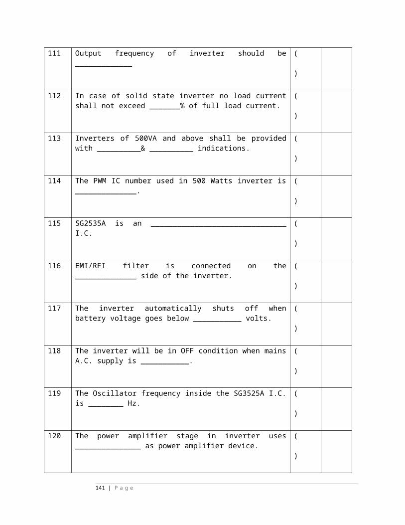
indication bul
7 Button assembly can be provided in compartments-------&-------- A) 3&8 B)6&7 C)7&8 D) 8&9 E)none
( )
A) 3&8
8 Point locking indication can be given in compartment-----A) 3 B) 8 C) 13 D) 3&13 E) none
( )
B) 8
9 Track indication when TPR’s are in drop condition is given in---&----A) 6&10 B)7&9 C)6&9 D)7&10 E)none
( )
B)7&9
10 Track indication when TPR’s are in pick up condition is given in---&----A) 6&10 B)7&9 C)6&9 D)7&10 E)none
( )
A) 6&10
11 top plate is combination of --------- platesA) 1 B) 2 C) 3 D) 4 E)none
( )
C) 3
12 upper plate of top plate is of ------------- ( C
141 | P a g e
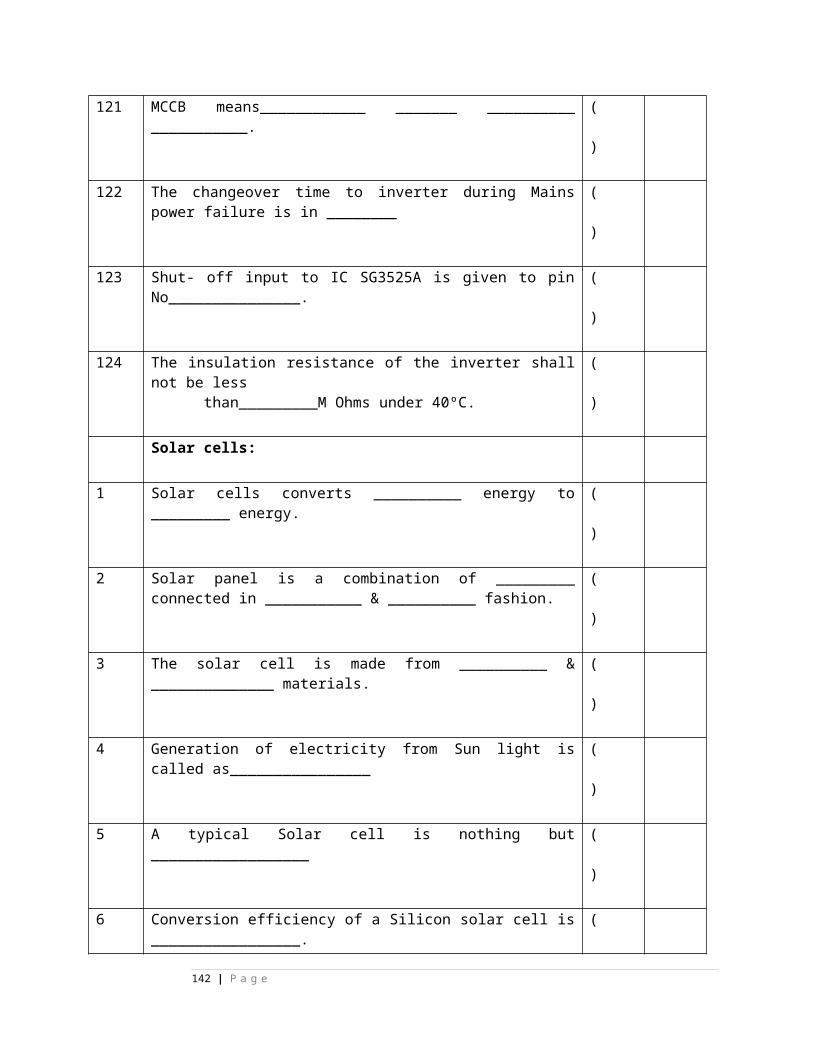
A) copper B) brass C) steel D) aluminum E) none
) ) steel
13 Location of compartment is given by--------A) CR B)CRC C)CCR D) CRR E)none
( )
C)CCR
14 on panel desk, on track drawing ----&----- buttons are provided A) GN&UN B)GN&WN C) WN&WWN D)SHGN&WN E) NONE
( )
A) GN&UN
15 indication of ON aspect of any signal is given in -----or------- ButtonsA) 3 or 13 B)3 or 8 C) 8 or 13 D) 3&8 E)none
( )
A) 3 or 13
16 colour of GN button is -------A) yellow B) red C) blue D) blue with white dot E)grey
( )
B) red
17 colour of UN button is ------- A) yellow B) red C) blue D) blue with white dot E)grey
( )
E)grey
18 colour of WN button is ------- A) yellow B) red C) blue D) blue with white dot
( )
C) blue
142 | P a g e
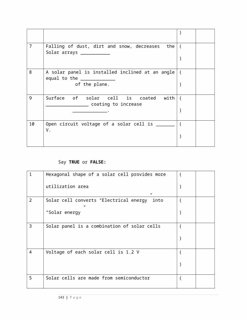
E)grey19 colour of WWN button is -------
A) yellow B) red C) blue D) blue with white dot E)grey
( )
C) blue
20 colour of EGGN button is ------- A) yellow B) red C) blue D) blue with white dot E)grey
( )
B) red
21 colour of EUUYN button is ------- A) yellow B) red C) blue D) blue with white dot E)grey
( )
E)grey
22 colour of EUYN button is ------- A) yellow B) red C) blue D) blue with white dot E)grey
( )
D) blue with white dot
23 colour of SHGN button is ------- A) yellow B) red C) blue D) blue with white dot E)grey
( )
A) yellow
24 colour of YYN button is ------- A) yellow B) red C) blue D) blue with white dot E)grey
( )
E)grey
25 colour of YRN button is -------
A) yellow B) red C) blue D) blue with white dot E)grey
( )
E)grey
26 colour of OYN button is ------- A) yellow B) red C) blue D) blue with white dot
( )
E)grey
143 | P a g e
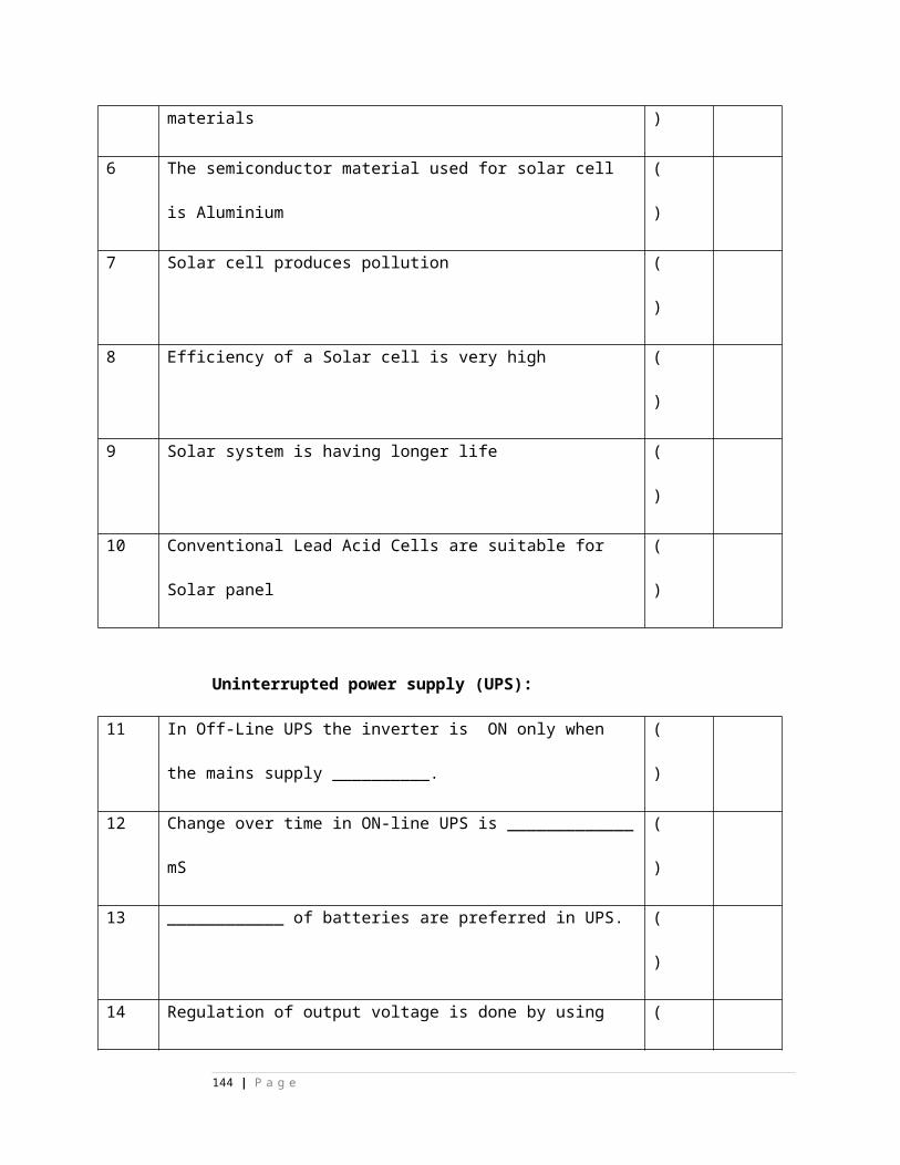
E)grey27 colour of CHYN button is -------
A) yellow B) red C) blue D) blue with white dot E)green
( )
E)green
28 colour of LXN button is -------
A) yellow B) red C) blue D) blue with white dot E)grey
( )
E)grey
29 colour of WN button( with subroute cancellation facility) is ------- A) yellow B) red C) blue D) blue with white dot E)grey
( )
D) blue with white dot
30 colour of EWN button is ------- A) yellow B) red C) blue D) blue with white dot E)grey
( )
C) blue
31 Sealing arrangement is provided for --------------A) EWN B) EUYYN C)EGGN D) OYN E)none
( )
A) EWN
32 full route cancellation is done by------- A) EWN B) EUYYN C)EGGN D) OYN E)none
( )
E)none
33 sub route cancellation is done by------- A) EWN B) EUYYN C)EGGN D) OYN E)EUYN
( )
E)E
144 | P a g e
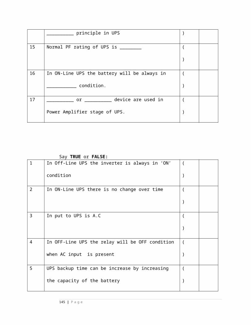
UYN
34 full route cancellation counter is ----------- A) EUYZ B)EUYYZ C)EUUYZ D)EEUYZ E)EWZ
( )
C)EUUYZ
35 Subroute cancellation counter is -----------A) EUYZ B)EUYYZ C)EUUYZ D)EEUYZ E)EWZ
( )
A) EUYZ
36 overlap cancellation counter is ----------- A) EUYZ B)EUYYZ C)EUUYZ D)OYZ E)EWZ
( )
D)OYZ
37 Calling on clearance counter is ----------- A) EUYZ B)EUYYZ C)EUUYZ D)COGGZ E)EWZ
( )
D)COGGZ
38 emergency point operation counter is ----------- A) EUYZ B)EUYYZ C)EUUYZ D)EEUYZ E)EWZ
( )
E)EWZ
39 key interlocking is provided to ------------- A) EWN B) EUYYN C)EGGN D) OYN E)EUYN
( )
E)EU
145 | P a g e
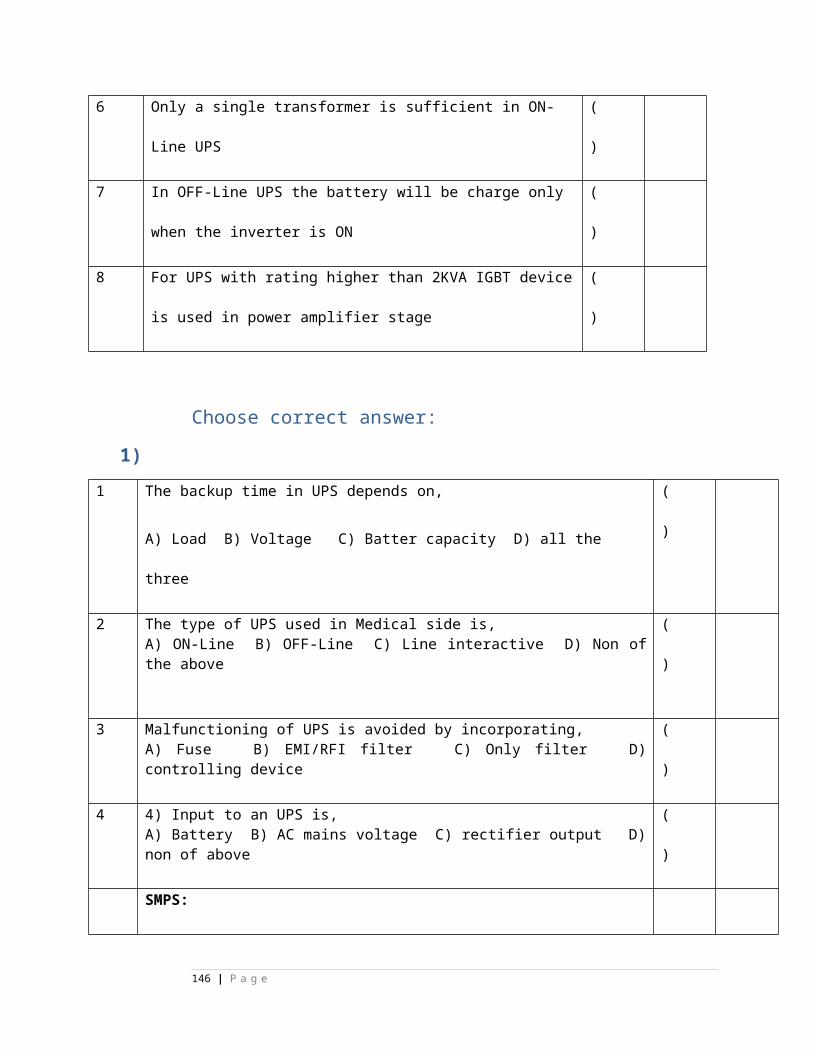
YN
40 EUYN operation can be done by--------- A) ESM III B)ESM II C)ESM I D) Helper khalashi E) none
( )
C)ESM I
Relay rack and arrangement
1. color of wire of Amphenol pin 1 is-----A)blue B) red C)grey D)green E)none
( )
A)blue
2. color of wire of Amphenol pin 2is----- A)blue B) red C)grey D)green E)none
( )
A)blu
146 | P a g e
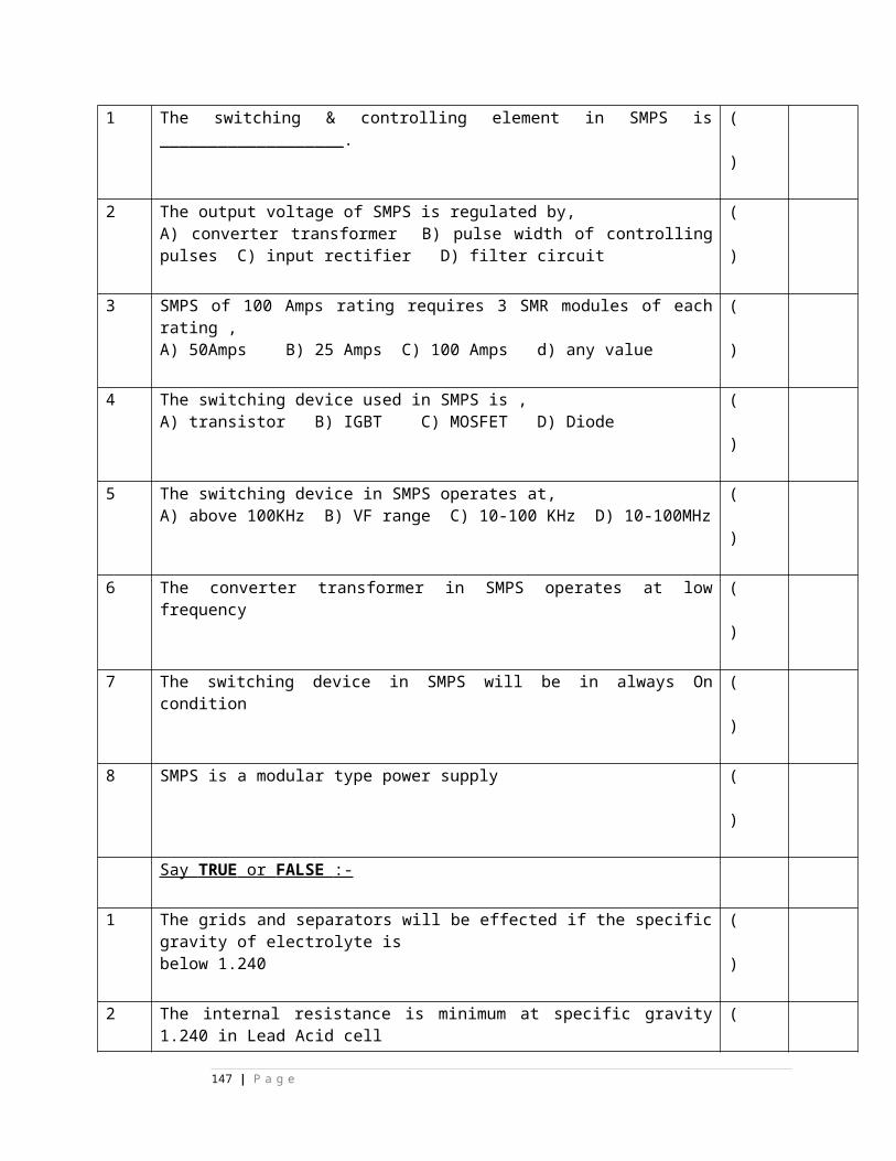
e 3. color of wire of Amphenol pin 3is-----
A)blue B) red C)grey D)green E)none
( )
A)blue
4. color of wire of Amphenol pin 4 is----- A)blue B) red C)grey D)green E)none
( )
A)blue
5. color of wire of Amphenol pin 11 is----- A)blue B) red C)grey D)green E)none
( )
B) red
6. color of wire of Amphenol pin 12 is----- A)blue B) red C)grey D)green E)none
( )
B) red
7. color of wire of Amphenol pin 13 is----- A)blue B) red C)grey D)green E)none
( )
B) red
8. color of wire of Amphenol pin 14 is----- A)blue B) red C)grey D)green E)none
( )
B) red
9. color of wire of Amphenol pin 21 is----- A)blue B) red C)grey D)green E)none
( )
C)gr
147 | P a g e
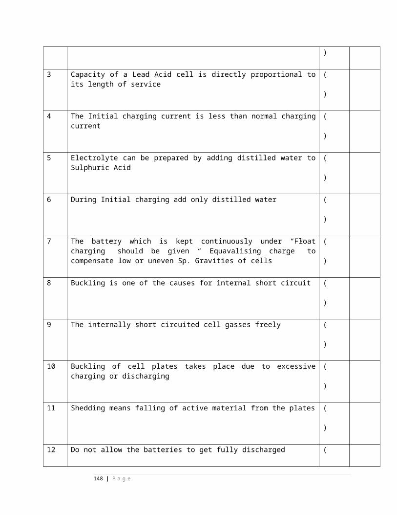
ey
10. color of wire of Amphenol pin 31 is----- A)blue B) red C)grey D)green E)none
( )
D)green
11. color of wire of Amphenol pin 32 is----- A)blue B) red C)grey D)green E)none
( )
D)green
12. color of wire of Amphenol pin 33 is----- A)blue B) red C)grey D)green E)none
( )
D)green
13. color of wire of Amphenol pin 34 is----- A)blue B) red C)grey D)green E)none
( )
D)green
14. color of wire of Amphenol pin 41 is----- A)blue B) red C)grey D)green E)none
( )
E)none
15. color of wire of Amphenol pin 42 is----- ( E
148 | P a g e
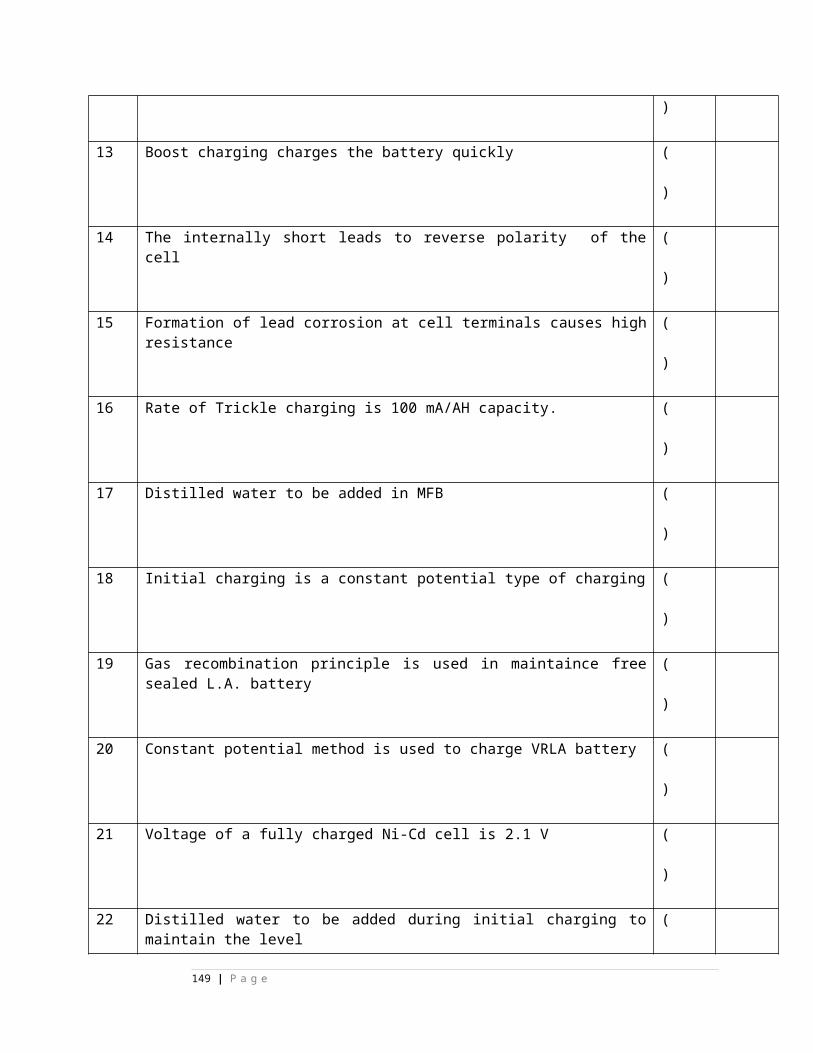
A)blue B) red C)grey D)green E)none
) )none
16. color of wire of Amphenol pin 43 is-----A)blue B) red C)grey D)green E)none
( )
E)none
17. color of wire of Amphenol pin 44 is-----A)blue B) red C)grey D)green E)none
( )
E)none
18. color of wire of Amphenol pin 51 is-----A)blue B) red C)grey D)green E)none
( )
E)none
19. color of wire of Amphenol pin 52 is----- A)blue B) red C)grey D)green E)none
( )
E)none
20. color of wire of Amphenol pin 53 is----- A)blue B) red C)grey D)green E)none
( )
E)none
21. color of wire of Amphenol pin 54 is----- A)blue B) red C)grey
( )
E)
149 | P a g e
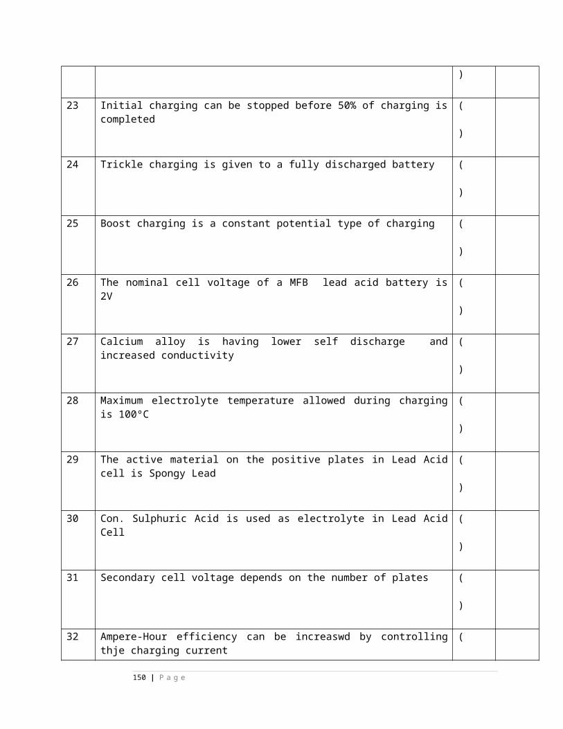
D)green E)none none
22. color of wire of Amphenol pin 22 is-----A)blue B) red C)grey D)green E)none
( )
E)none
23. color of wire of Amphenol pin 61 is-----A)brown B) black C)yellow D)white E)none
( )
C)yellow
24. color of wire of Amphenol pin 62 is-----A)brown B) black C)yellow D)white E)none
( )
C)yellow
25. color of wire of Amphenol pin 63 is-----A)brown B) black C)yellow D)white E)none
( )
C)yellow
26. color of wire of Amphenol pin 64 is-----A)brown B) black C)yellow D)white E)none
( )
C)y
150 | P a g e
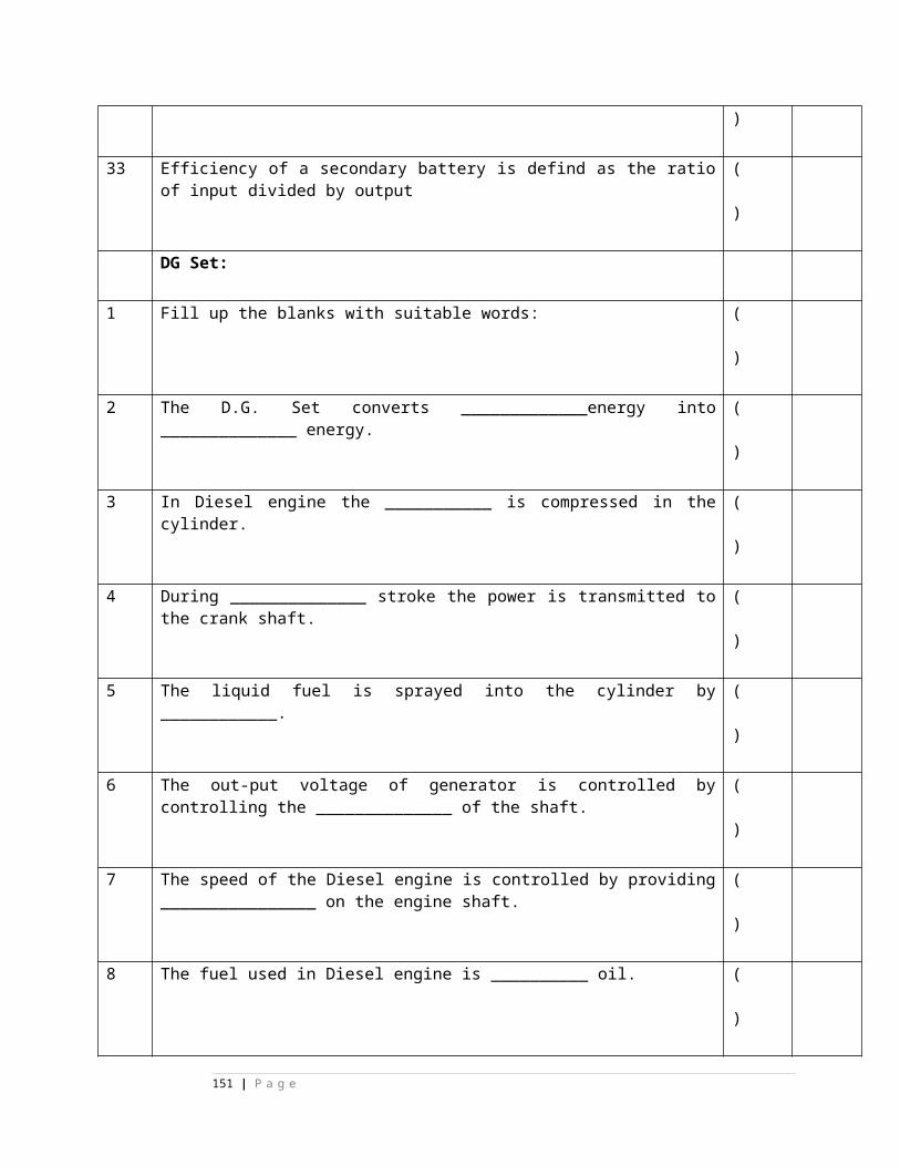
ellow
27. color of wire of Amphenol pin 71 is----- A)brown B) black C)yellow D)white E)none
( )
D)white
28. color of wire of Amphenol pin 72 is----- A)brown B) black C)yellow D)white E)none
( )
D)white
29. color of wire of Amphenol pin 73is-----A)brown B) black C)yellow D)white E)none
( )
D)white
30. color of wire of Amphenol pin 74 is-----A)brown B) black C)yellow D)white E)none
( )
D)white
31. color of wire of Amphenol pin 81 is-----A)brown B) black C)yellow D)white E)none
( )
E)none
32. color of wire of Amphenol pin 82 is----- A)brown B) black C)yellow
( )
E)
151 | P a g e
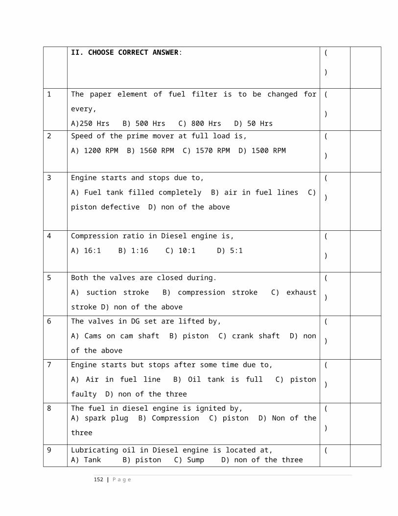
D)white E)none none
33. color of wire of Amphenol pin 83 is----- A)brown B) black C)yellow D)white E)none
( )
E)none
34. color of wire of Amphenol pin 84 is-----A)brown B) black C)yellow D)white E)none
( )
E)none
35. color of wire of Amphenol pin 91 is-----A)brown B) black C)yellow D)white E)none
( )
E)none
36. color of wire of Amphenol pin 92 is----- A) brown B) black C)yellow D)white E)none
( )
E)none
37. color of wire of Amphenol pin 93 is-----A) brown B) black C)yellow D)white E)none
( )
E)none
38. color of wire of Amphenol pin 94 is-----A) brown B) black C)yellow D)white E)none
( )
E)n
152 | P a g e
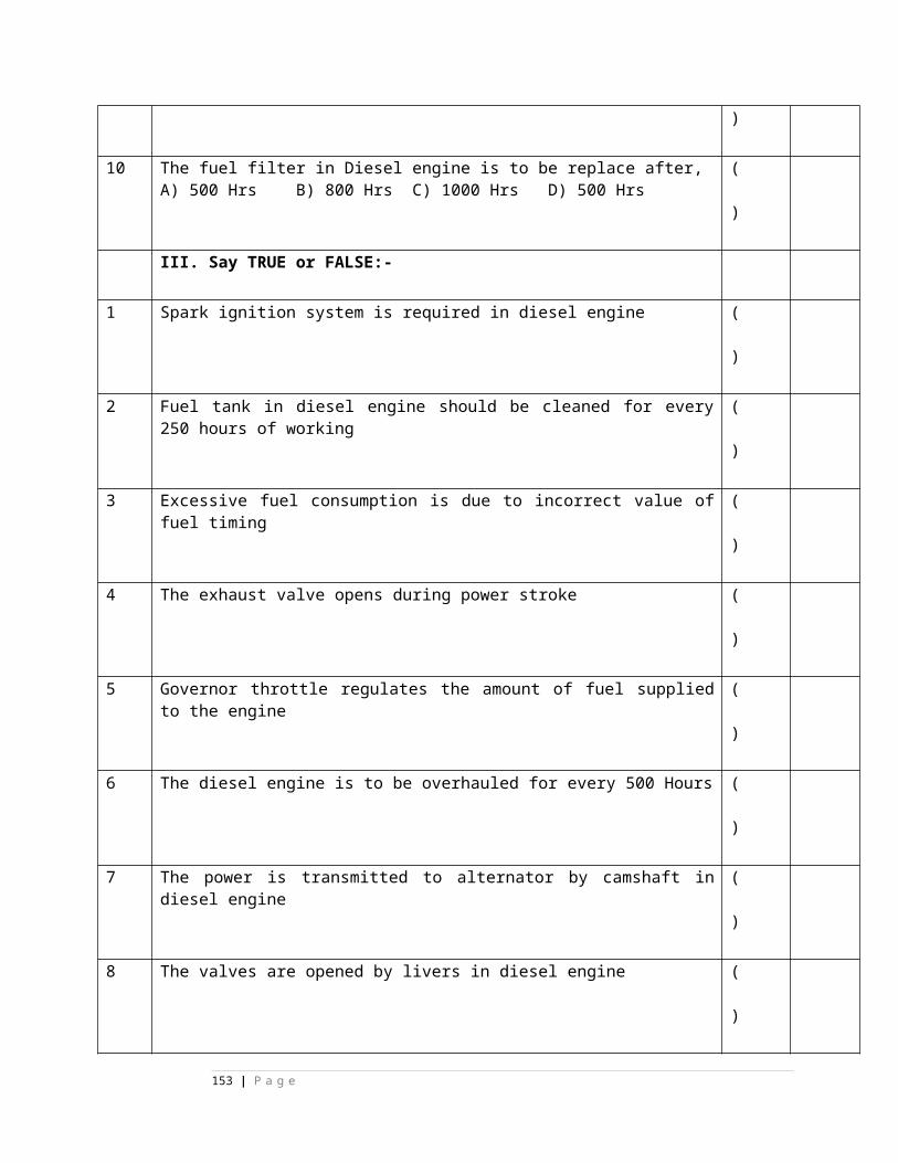
one
39. color of wire of Amphenol pin 23 is-----A) brown B) black C)yellow D)white E)none
( )
E)none
40. color of wire of Amphenol pin 24 is-----A) pink B) black C) purple D)white E)none
( )
E)none
41. color of wire of Amphenol pin 1 is-----A) pink B) black C) purple D)white E)none
( )
E)none
42. color of wire of Amphenol pin 2is-----A) pink B) black C) purple D)white E)none
( )
E)none
43. color of wire of Amphenol pin 3is-----A) pink B) black C) purple D)white E)none
( )
E)none
44. color of wire of Amphenol pin 4is-----A) pink B) black C) purple D)white E)none
( )
E)no
153 | P a g e
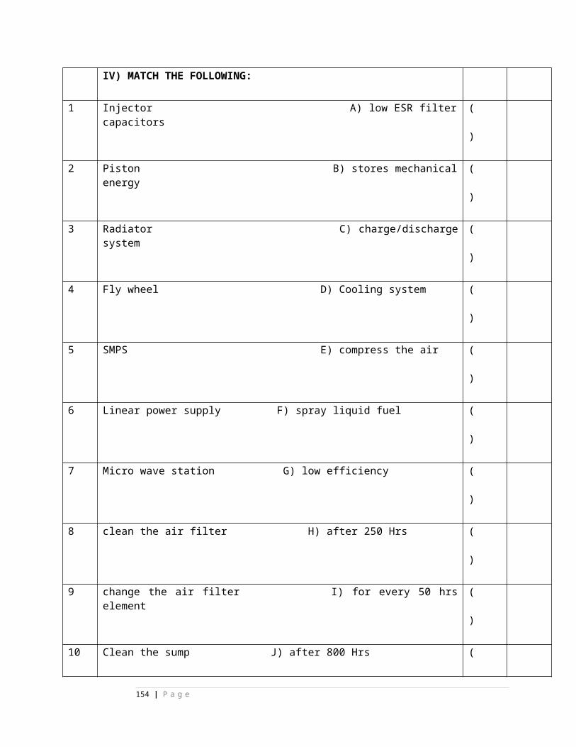
ne
45. color of wire of Amphenol pin 11is-----A) pink B) black C) purple D)white E)none
( )
E)none
46. color of wire of Amphenol pin 12is-----A) pink B) black C) purple D)white E)none
( )
E)none
47. color of wire of Amphenol pin 13is-----A) pink B) black C) purple D)white E)none
( )
E)none
48. color of wire of Amphenol pin 14is-----A) pink B) black C) purple D)white E)none
( )
E)none
49. color of wire of Amphenol pin 21is-----A) pink B) black C) purple D)white E)none
( )
E)none
50. color of wire of Amphenol pin 22is-----A) pink B) black C) purple D)white E)none
( )
E)non
154 | P a g e
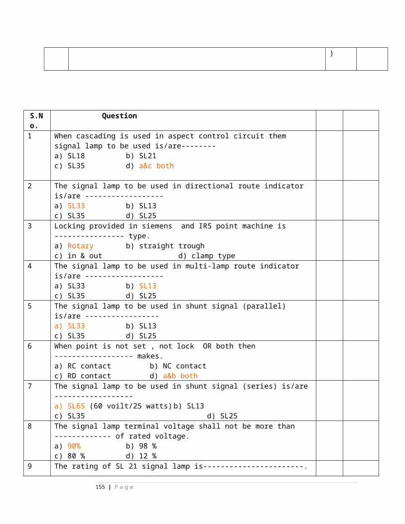
e51. color of wire of Amphenol pin 23is-----
A) pink B) black C) purple D)white E)none
( )
E)none
52. color of wire of Amphenol pin 24is-----A) pink B) black C) purple D)white E)none
( )
E)none
53. color of wire of Amphenol pin 31is-----A) pink B) black C) purple D)white E)none
( )
E)none
54. color of wire of Amphenol pin 32is-----A) pink B) black C) purple D)white E)none
( )
E)none
55. color of wire of Amphenol pin 33is-----A) pink B) black C) purple D)white E)none
( )
E)none
56. color of wire of Amphenol pin 34is-----A) pink B) black C) purple D)white E)none
( )
E)none
155 | P a g e
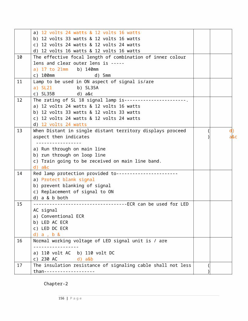
57. color of wire of Amphenol pin 41is-----A) pink B) black C) purple D)white E)none
( )
E)none
58. color of wire of Amphenol pin 42is-----A) pink B) black C) purple D)white E)none
( )
E)none
59. color of wire of Amphenol pin 43is-----A) pink B) black C) purple D)white E)none
( )
E)none
60. color of wire of Amphenol pin 44is-----A) pink B) black C) purple D)white E)none
( )
E)none
61. color of wire of Amphenol pin 51is-----A) pink B) black C) purple D)white E)none
( )
B) black
62. color of wire of Amphenol pin 52 is-----A) pink B) black C) purple D)white E)none
( )
B) blac
156 | P a g e
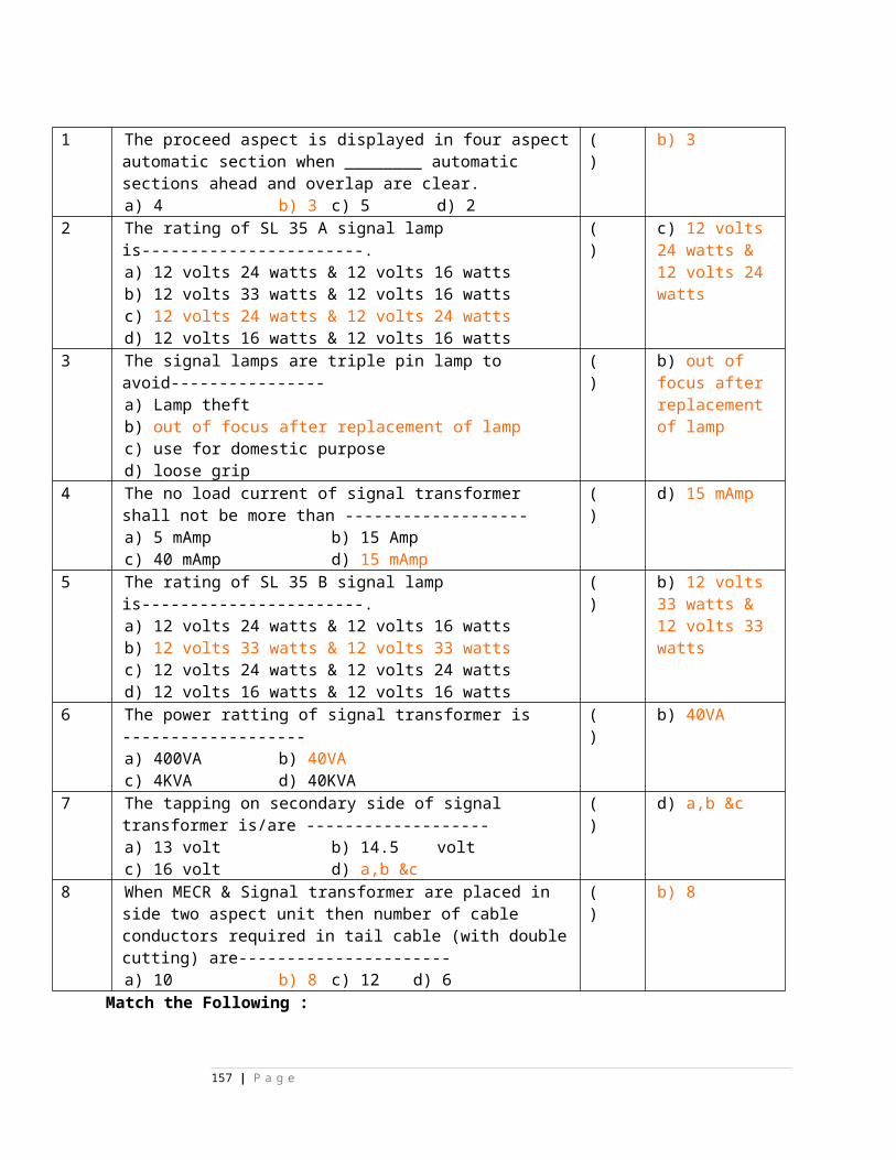
k 63. color of wire of Amphenol pin 53 is-----
A) pink B) black C) purple D)white E)none
( )
B) black
64. color of wire of Amphenol pin 54is-----A) pink B) black C) purple D)white E)none
( )
B) black
65. color of wire of Amphenol pin 61 is-----A) pink B) black C) purple D)white E)none
( )
E)none
66. color of wire of Amphenol pin 62 is-----A) pink B) black C) purple D)white E)none
( )
E)none
67. color of wire of Amphenol pin 63 is-----A) pink B) black C) purple D)white E)none
( )
E)none
68. color of wire of Amphenol pin 64 is-----A) pink B) black C) purple D)white E)none
( )
E)no
157 | P a g e
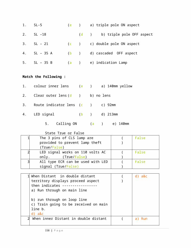
ne
69. color of wire of Amphenol pin 71 is-----A) pink B) black C) purple D)blue E)none
( )
A) pink
70. color of wire of Amphenol pin 72 is-----A) pink B) black C) purple D)blue E)none
( )
A) pink
71. in Siemens relay ,continuity of contact ------ is available in between Amphenol terminal 11 &12A) 01.01 B) 02.01 C)03.01 D)04.01 E)none
( )
B) 02.01
72. in Siemens relay ,continuity of contact ------ is available in between Amphenol terminal 21 &22A) 01.01 B) 02.01 C)03.01 D)04.01 E)none
( )
C)03.01
73. in Siemens relay ,continuity of contact ------ is available in between Amphenol terminal 31 &32 A) 01.01 B) 02.01 C)03.01 D)04.01 E)none
( )
D)04.01
158 | P a g e
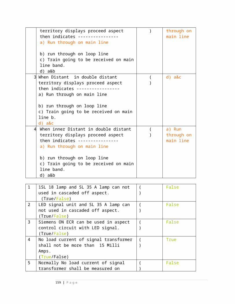
74. in Siemens relay ,continuity of contact ------ is available in between Amphenol terminal 41 &42 A) 01.01 B) 02.01 C)03.01 D)04.01 E)none
( )
E)none
75. in Siemens relay ,continuity of contact ------ is available in between Amphenol terminal 51 &52A) 01.01 B) 02.01 C)03.01 D)04.01 E)none
( )
E)none
76. in Siemens relay ,continuity of contact ------ is available in between Amphenol terminal 61 &62A) 05.02 B) 15.02 C)03.01 D)04.01 E)none
( )
E)none
77. in Siemens relay ,continuity of contact ------ is available in between Amphenol terminal 71 &72 A) 13.01 B) 14.01 C)03.01 D)04.01 E)none
( )
A) 13.01
78. in Siemens relay ,continuity of contact ------ is available in between Amphenol terminal 81 &82 A) 13.01 B) 14.01 C)03.01 D)04.01 E)none
( )
E)none
79. in Siemens relay ,continuity of contact ------ is available in between Amphenol terminal 91 &92A) 13.01 B) 14.01 C)03.01 D)11.02 E)none
( )
E)none
159 | P a g e
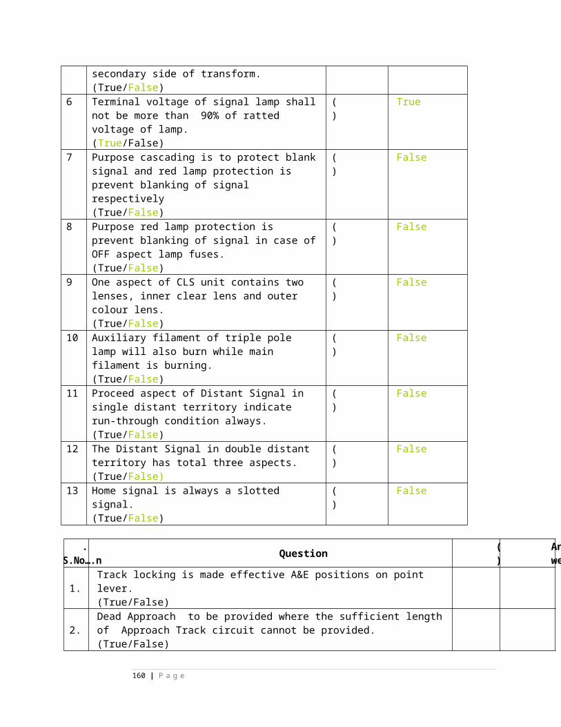
80. in Siemens relay ,continuity of contact ------ is available in between Amphenol terminal 13 &14 A) 01.01 B) 02.01 C)03.01 D)04.01 E)none
( )
E)none
81. in Siemens relay ,continuity of contact ------ is available in between Amphenol terminal 23 &24A) 01.01 B) 02.01 C)03.02 D)04.01 E)none
( )
C)03.02
82. in Siemens relay ,continuity of contact ------ is available in between Amphenol terminal 33 &34A) 01.01 B) 02.01 C)03.01 D)04.02 E)none
( )
D)04.02
83. in Siemens relay ,continuity of contact ------ is available in between Amphenol terminal 43 &44 A) 01.01 B) 05.02 C)03.02 D)04.02 E)none
( )
B) 05.02
84. in Siemens relay ,continuity of contact ------ is available in between Amphenol terminal 53 &54A) 15.02 B) 05.02 C)03.02 D)04.02 E)none
( )
85. in Siemens relay ,continuity of contact ------ is available in between Amphenol terminal 63 & 64A) 15.02 B) 14.02 C) 13..02 D) 11.02 E)none
( )
B) 14.
160 | P a g e
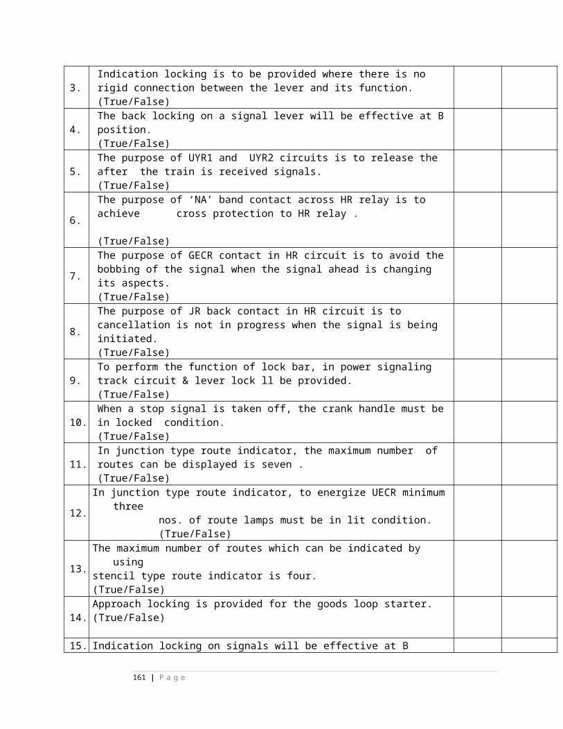
02
86. in Siemens relay ,continuity of contact ------ is available in between Amphenol terminal 73 & 74A) 15.02 B) 14.02 C) 13..02 D) 11.02 E)none
( )
C) 13..02
87. in Siemens relay ,continuity of contact ------ is available in between Amphenol terminal 83 & 84A) 15.02 B) 14.02 C) 13..02 D) 11.02 E)none
( )
E)none
88. in Siemens relay ,continuity of contact ------ is available in between Amphenol terminal 93 & 94A) 15.02 B) 14.02 C) 13..02 D) 11.02 E)none
( )
D) 11.02
89. in Siemens relay ,continuity of contact ------ is available in between Amphenol terminal 93 & 94A) 15.02 B) 14.02 C) 13..02 D) 11.01 E)none
( )
E)none
90. in Siemens relay ,continuity of contact ------ is available in between Amphenol terminal 83 & 84A) 15.02 B) 14.02 C) 13..02 D) 12.02 E)none
( )
D) 12.02
91. 160 pin tag block can accommodate ----------mini groups
( )
D)
161 | P a g e
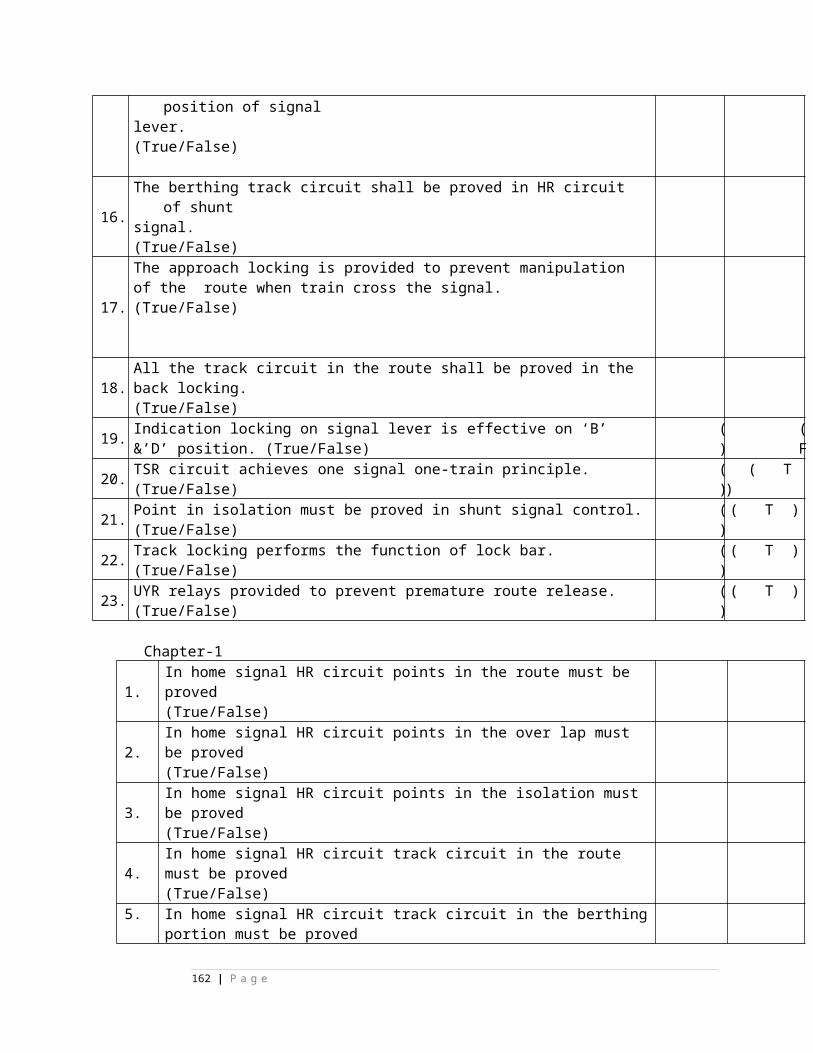
A) 1 B) 2 C) 3 D)4 E)none 4 92. 200 pin tag block can accommodate ----------
mini groupsA) 1 B) 2 C) 3 D)4 E)none
( )
E)none
93. 160 pin tag block can accommodate ----------minor groupsA) 1 B) 2 C) 3 D)4 E)none
( )
E)none
94. 200 pin tag block can accommodate ----------minor groupsA) 1 B) 2 C) 3 D)4 E)none
( )
B) 2
95. 200 pin tag block can accommodate ----------major groupsA) 1 B) 2 C) 3 D)4 E)none
( )
A) 1
96. one ‘G’ type fuse block can accommodate -------fuses.A) 91 B) 93 C) 95 D) 96 E)none
( )
D) 96
97. in one ‘G’ type max fuse strip -----fuses are available
( )
98. one relay rack can accommodate ---------mini groups A)16 B) 64 C) 8 D) 8x2 E) none
( )
B) 64
99. one relay rack can accommodate ---------minor groups A)16 B) 64 C) 8 D) 8x8 E) none
( )
A)16
100. one relay rack can accommodate ---------major groups
( )
C)
162 | P a g e
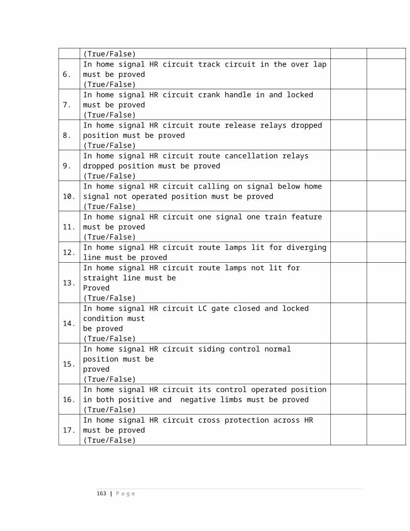
A)16 B) 64 C) 8 D) 8x2 E) none 8 101. one relay rack can accommodate ---------major
groups A)2x4 B) 2x8 C) 8x8 D) 4x2 E) none
( )
A)2x4
102. one relay rack can accommodate ---------minor groups A)2x4 B) 2x8 C) 8x8 D) 4x4 E) none
( )
D) 4x4
103. one relay rack can accommodate ---------mini groups A)2x4 B) 2x8 C) 8x8 D) 4x4 E) none
( )
C) 8x8
104. relay space provided in mini group is----------A) 2 B) 15 C) 30 D) 1 E) none
( )
A) 2
105. relay space provided in minor group is----------A) 2 B) 15 C) 30 D) 1 E) none
( )
B) 15
106. relay space provided in major group is----------A) 2 B) 15 C) 30 D) 23+1 E) none
( )
C) 30
107. relay space provided in point minor group is----------A) 2 B) 15 C) 30 D) 11+1 E) none
( )
B) 15
108. relay space provided in signal minor group is----------A) 2 B) 15 C) 30 D) 11+1 E) none
( )
B) 15
109. relay space provided in shunt minor group ( B
163 | P a g e
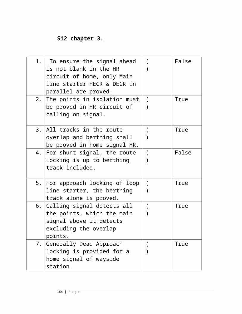
is----------A) 13 B) 15 C) 30 D) 11+1 E) none
) ) 15
110. relay space provided in route minor group is----------A) 13 B) 15 C) 11 D) 11+1 E) none
( )
B) 15
111. relays provided in point minor group are--------A) 2 B) 15 C) 30 D) 11+1 E) none
( )
D) 11+1
112. relays provided in 2A signal minor group are ---------- A) 13 B) 15 C) 30 D) 11+1 E)none
( )
E) none
113. relays provided in 3A signal minor group are ----------A) 13 B) 15 C) 30 D) 11+1 E) none
( )
A) 13
114. relays provided in point major group -----------A) 30 B)15 C) 23+1 D) 11+1 E) none
( )
C) 23+1
115. relays provided in point chain group -----------A) 8 B)15 C) 23+1 D) 11+1 E) none
( )
A) 8
116. indications provided on 2A signal minor group are -----------A) 1 B) 2 C) 3 D) 4 E) none
( )
B) 2
117. indications provided on 3A signal minor group ( B
164 | P a g e
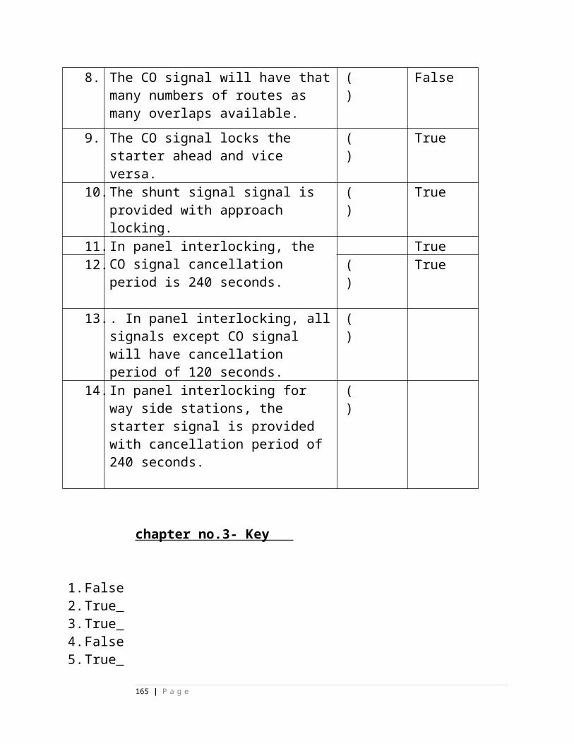
are -----------A) 1 B) 2 C) 3 D) 4 E) none
) ) 2
118. indications provided on point minor group are -----------A) 1 B) 2 C) 3 D) 4 E) none
( )
A) 1
119. indications provided on point major group are -----------A) 1 B) 2 C) 3 D) 4 E) none
( )
C) 3
120. indications provided on route minor group are -----------A) 1 B) 2 C) 3 D) 4 E) none
( )
B) 2
121. indications provided on shunt signal minor group are -----------A) 1 B) 2 C) 3 D) 4 E) none
( )
D) 4
122. indications provided on point chain group are -----------A) 1 B) 2 C) 3 D) 4 E) none
( )
E) none
123. indications provided on 2A signal minor group are -----------A) RKE,DKE B) REK.DK C) RKE D) HKE E) none
( )
A) RKE,DKE
124. indications provided on 3A signal minor group are -----------A) RKE,DKE B) REK.DK C) RKE D) HKE E) none
( )
A) RKE,DK
165 | P a g e
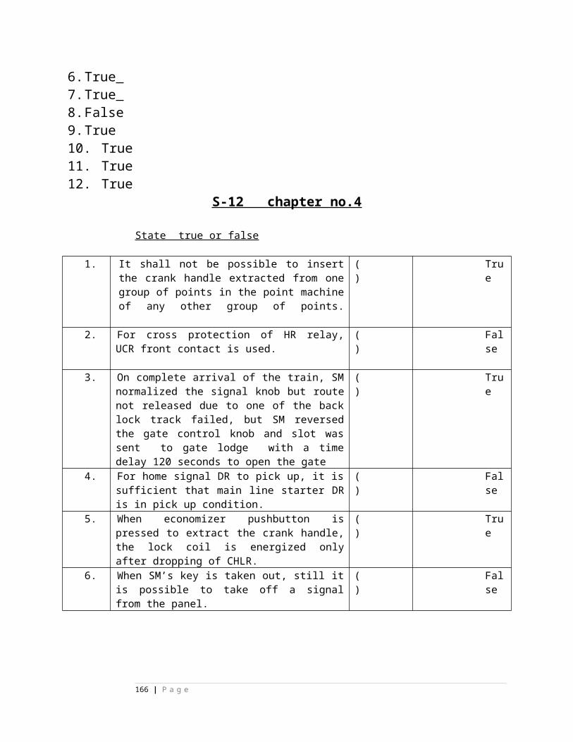
E 125. indications provided on POINT minor group
are -----------A) RKE,DKE B) REK.DK C) RKE D) HKE E) none
( )
C) RKE
126. indications provided on point major group are -----------A) RKE,DKE B) REK.DK C) RKE D) HKE E) none
( )
E) none
127. indications provided on shunt signal minor group are -----------A) RKE,DKE B) RKE,HKE ,RKE,HKE C) RKE D) HKE E) none
( )
B) RKE,HKE ,RKE,HKE
128. indications provided on point chain group are -----------A) RKE,DKE B) RKE,HKE ,RKE,HKE C) RKE D) HKE E) none
( )
E) none
129. indications provided on route minor group are -----------
( )
A)
166 | P a g e
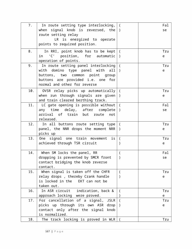
A) RKE,HKE B) RKE,HKE ,RKE,HKE C) RKE D) HKE E) none
RKE,HKE
130. indications provided on mini group are -----------A) RKE,DKE B) RKE,HKE ,RKE,HKE C) RKE D) HKE E) none
( )
E) none
131. MDF means--------------A)main distribution fuse B) main distant frame C) main distribution frame D) main distant fuseE) none
( )
C) main distribution frame
132. IDF means--------------A) Intermediate distribution fuse
( )
C)
167 | P a g e
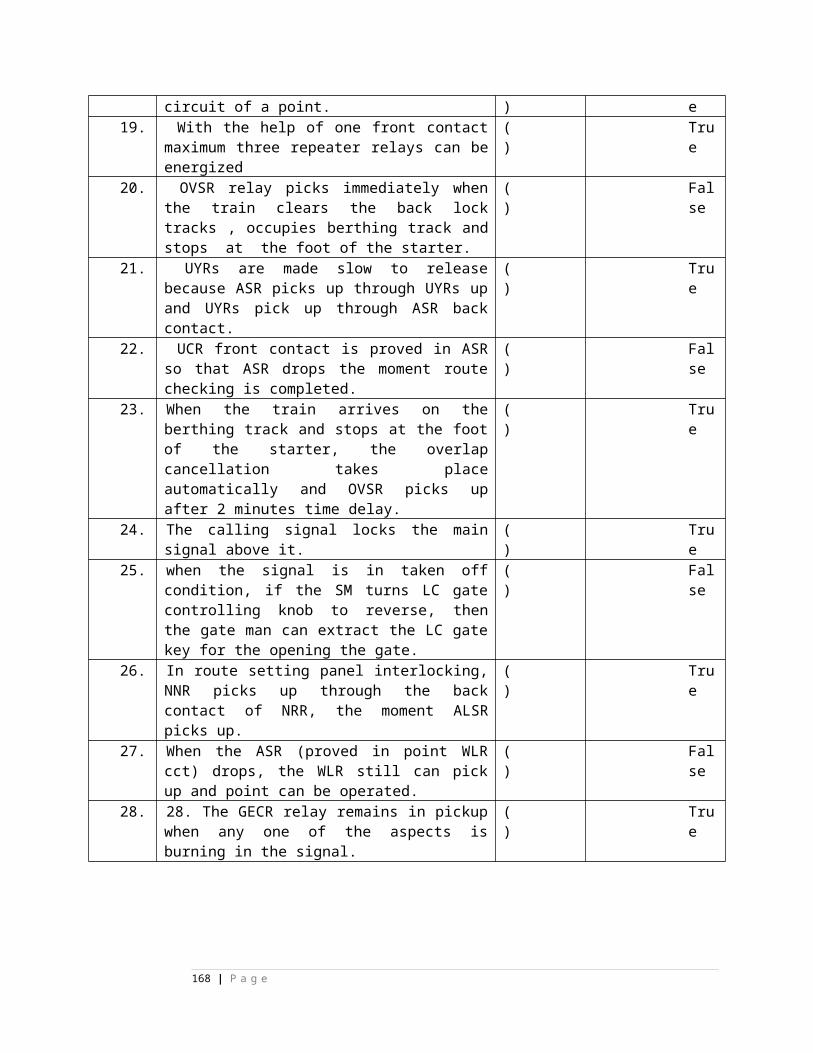
B) Intermediate distant frame C) Intermediate distribution frame D) main distribution frame E) none
Intermediate distribution frame
133. MDF is provided in ----------A) big yards B)small yards C)mid sections D) IBS E) none
( )
B)small yard
168 | P a g e
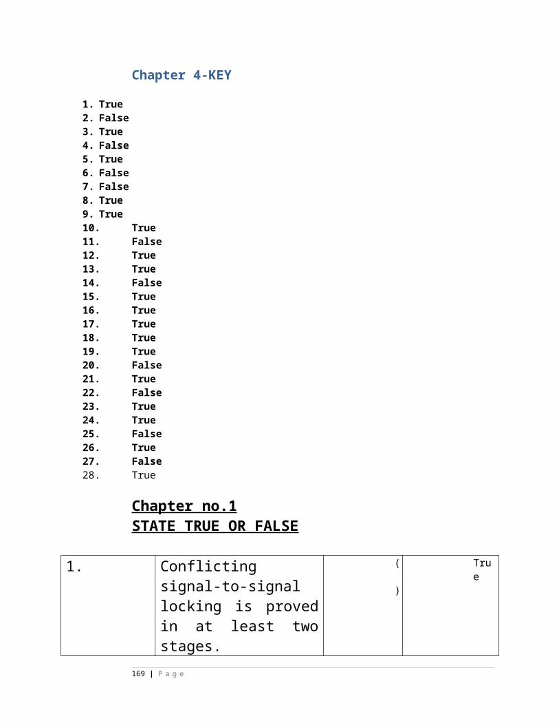
s 134. IDF is provided in ----------
A) big yards B)small yards C)mid sections D) IBS E) none
( )
A) big yards
135. In IDF tag block provided on one pillar are-------A) 4 B) 6 C) 8 D) 10 E) none
( )
D) 10
136. wiring from domino to panel desk tag block is done with A) 0.4mm dia indoor cable B) 0.4mm dia jumper wireC) 0.6mm dia indoor cable D) 0.6mm dia jumper wire E) none
( )
B) 0.4mm dia jumper wire
137. wiring from panel desk tag block to IDF is done with
( )
C)
169 | P a g e
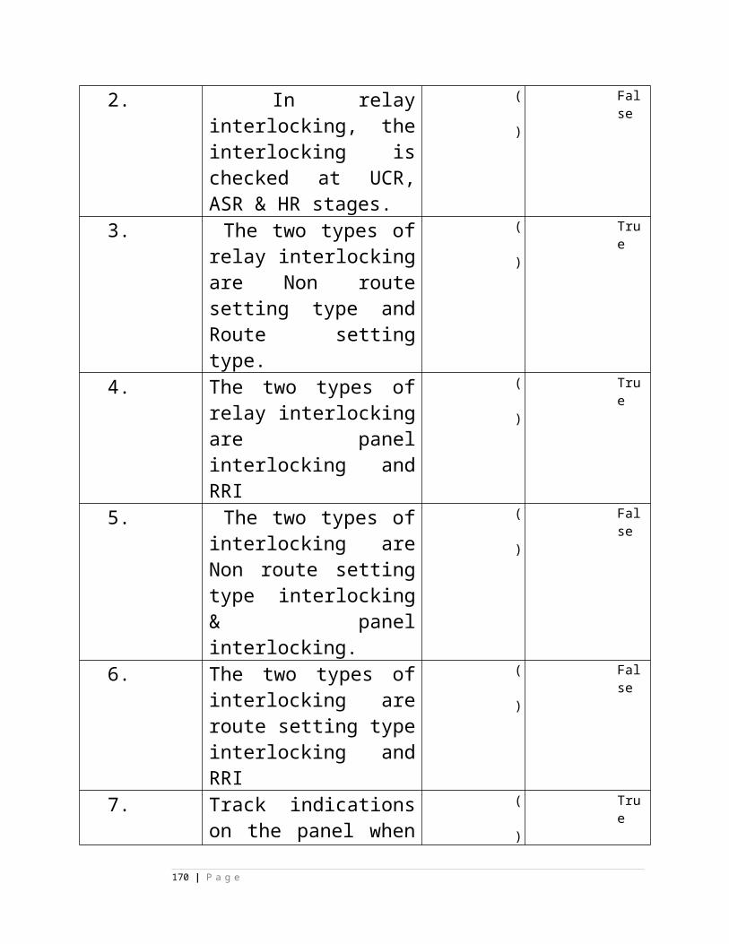
A) 0.4mm dia indoor cable B) 0.4mm dia jumper wireC) 0.6mm dia indoor cable D) 0.6mm dia jumper wire E) none
0.6mm dia indoor cable
138. wiring from tag block IDF to relay base plate is done with A) 0.4mm dia indoor cable B) 0.4mm dia jumper wireC) 0.6mm dia indoor cable D) 0.6mm dia jumper wire E) none
( )
C) 0.6mm dia indoor c
170 | P a g e
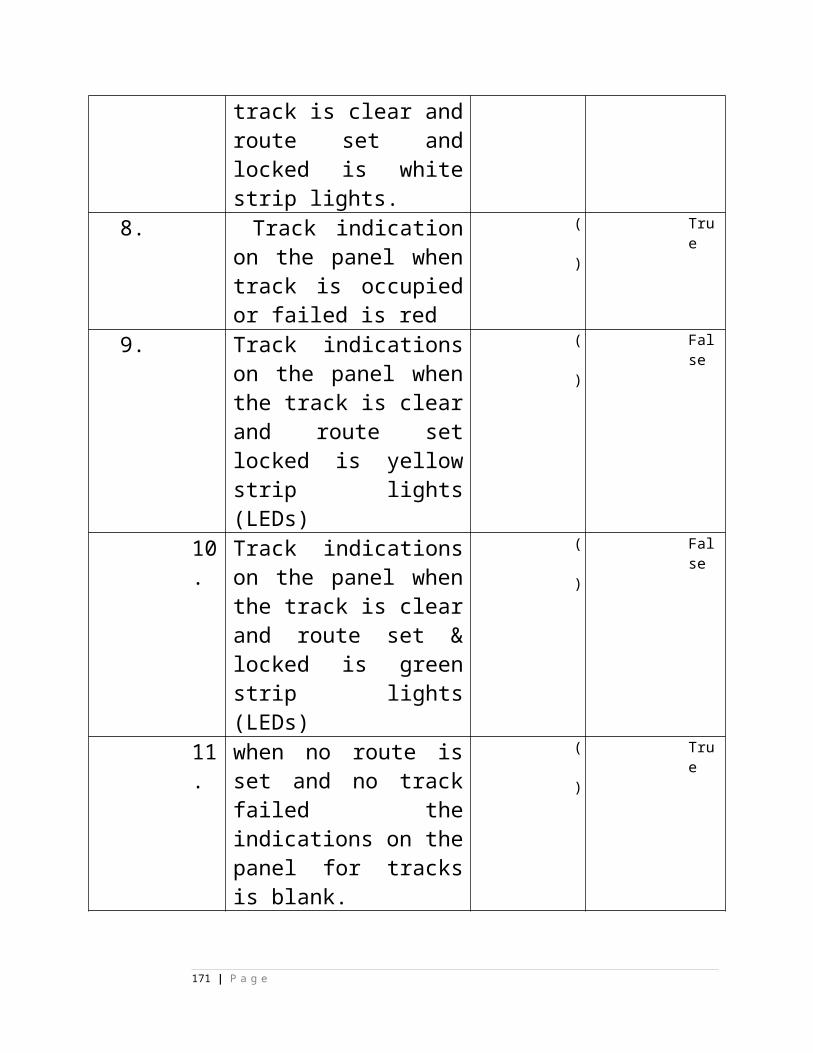
able
139. wiring from tag block IDF to tag block IDF is done with A) 0.4mm dia indoor cable B) 0.4mm dia jumper wireC) 0.6mm dia indoor cable D) 0.6mm dia jumper wire E) none
( )
D) 0.6mm dia jumper wire
140. wiring from tag block IDF to CT -- rack is done with A) 0.4mm dia indoor cable B) 0.4mm dia jumper wireC) 0.6mm dia indoor cable D) 0.6mm dia jumper wire E) none
( )
D) 0.6mm dia jum
171 | P a g e
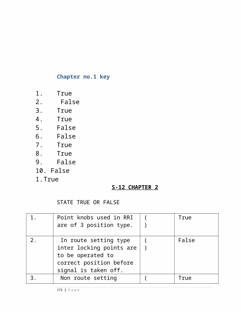
per wire
141. wiring from tag block IDF to CT - rack for point controlling ckt is done with A) 0.4mm dia indoor cable B) 0.4mm dia jumper wireC) 0.6mm dia indoor cable D) 0.6mm dia jumper wire E) none
( )
E) none
142. wiring from tag block IDF to CT - rack for sig lamp checking ckt is done with A) 0.4mm dia indoor cable B) 0.4mm dia jumper wireC) 0.6mm dia indoor cable D) 0.6mm dia jumper wire E) none
( )
E) none
143. On one terminal of tag block soldering of --------wires are allowed.A) 1 B)2 C) 3 D)4 E) none
( )
B)2
144. Inter distance between two racks should not be less than ---------- A) 1m B) 2m C) 3m D) 4m E) none
( )
A) 1m
145. distance between roof and top surface of rack should not be less than ---A) 1m B) 1.25m C) 1.35m D) 1.5m E) none
( )
D) 1.5m
146. distance between side wall and rack should not be less than ---
( )
D)
172 | P a g e
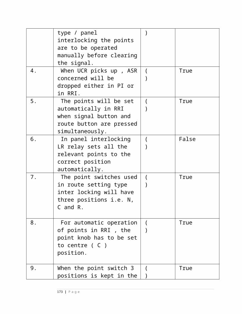
A) 1m B) 1.25m C) 1.35m D) 1.5m E) none
1.5m
147. distance between parallel wall and relay row should not be less than ---A) 1m B) 1.25m C) 1.35m D) 1.5m E) none
( )
D) 1.5m
148. distance between IDF and relay rack should not be less than ---A) 1m B) 1.25m C) 1.35m D) 1.5m E) none
( )
C) 1.35m
149. in panel desk --------tag pin is used normallyA)69 B) 160 C) 96 D) 40 E) none
( )
C) 96
150. point locking relay--------
A) B) C) D)
E) none
( )
A)
173 | P a g e
151. signal locking relay
A) B) C) D)
E) none
( )
B)
152. route locking relay
A) B) C) D)
E) none
( )
E) none
153. route locking interlocked relay coil ------------
A) B) C) D)
E) none
( )
E) none
154. interlocked relay normal coil front contact -----
A) B) C) D)
E) none
( )
E) none
155. interlocked relay reverse coil back contact------
A) B) C) D)
( )
B)
174 | P a g e
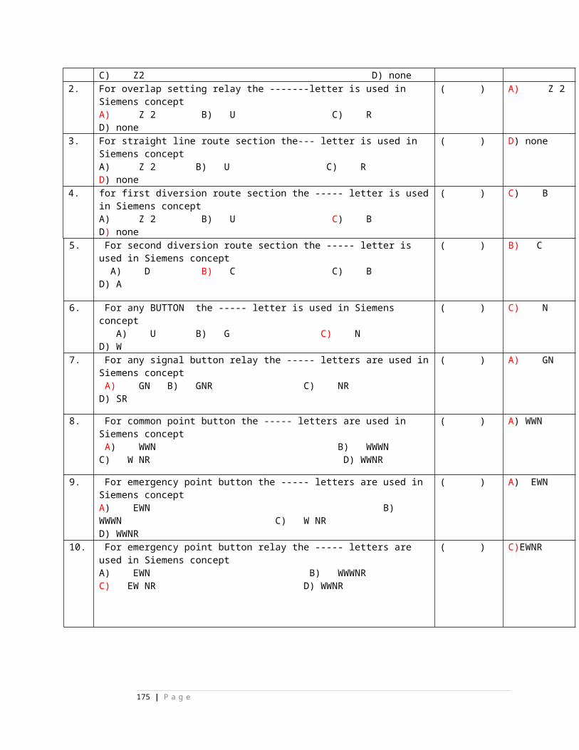
E) none156. neutral relay front contact-------
A) B) C) D)
E) none
( )
E) none
157. neutral relay back contact-------
A) B) C) D)
E) none
( )
A)
158. route checking relay
A) B) C) D)
E) none
( )
A)
159. route controlling relay
A) B) C) D)
E) none
( )
E) none
175 | P a g e
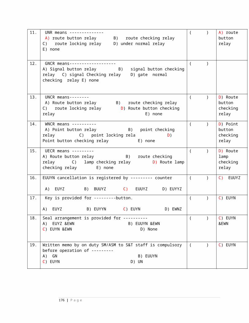
T
160. signal controlling relay
A) B) C) D)
E) none
( )
E) none
161. point contactor relay
A) B) C) D)
E) none
( )
B)
162. point time relay
A) B) C) D)
E) none
( )
E) none
163. track relay----
A) B) C) D)
E) none
( )
A)
164. point neutral locking relay--------
A) B) C) D)
( )
B)
176 | P a g e
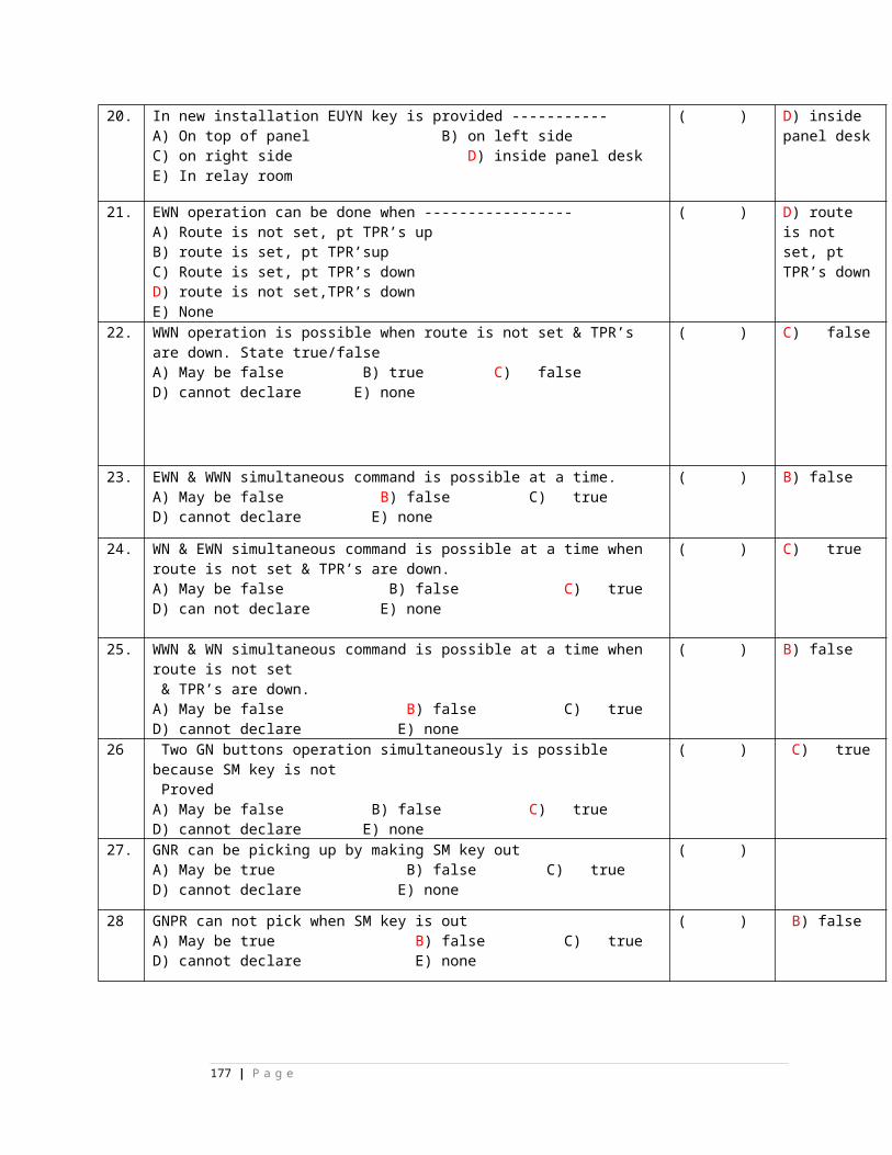
E) none165. signal indication neutral relay-------
A) B) C) D)
E) none
( )
E) none
166. track repeater relay------
A) B) C) D)
E) none
( )
E) none
167. in k-50 relays ------is always front contact A) 01 B) 11 C) 15 D) 02 E) none
( )
D) 02
168. in k-50 relays ------is always front contact A) 01 B) 11 C) 12 D) 05 E) none
( )
C) 12
169. in k-50 relays ------is always back contact (except ECRs)A) 01 B) 11 C) 12 D) 05 E) none
( )
D) 05
170. in k-50 relays ------is always back contact (except ECRs)A) 01 B) 11 C) 12 D) 15 E) none
( )
D) 15
177 | P a g e
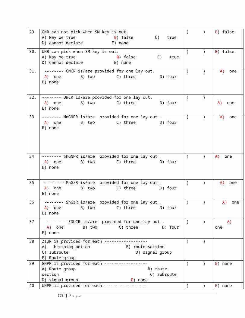
*******************************************************************************
CHAPTER 1
STATE TRUE or FALSE
1. In case of Electronic Interlocking System,
Non-Interlocking period is less
( )
(
T
)
2. In case of Electronic Interlocking System,
Standard of safety and reliability is higher as
compared with existing relay interlocking
systems.
( )
(
T
)
3. Datalogger / Event logger is not an integral
part of EI.
( )
(
F
)
4. Electronic Interlocking System is provided
with self-diagnostic in feature.
( )
(
T
)
178 | P a g e
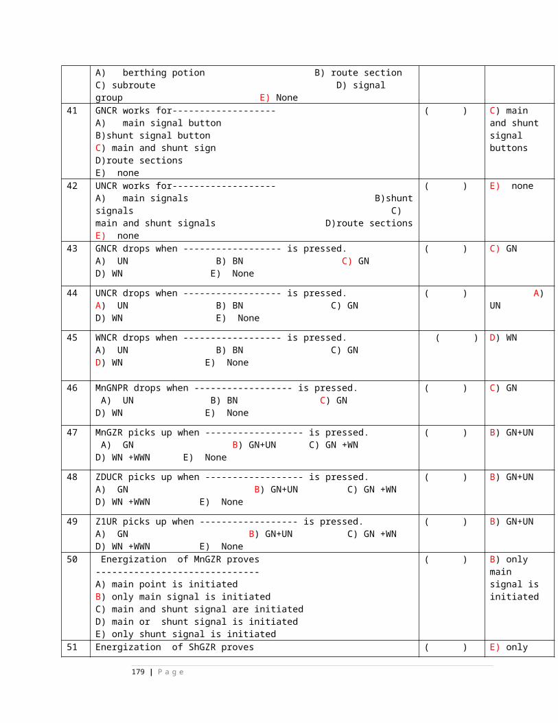
5. By using Object Controllers Main signalling
cables between Equipment Room (Relay
Room) and Location Box of field functions
can be eliminated.
( )
(
T
)
6. Microlok-II is a Dual hardware with software
diversity system.
( )
(
F
)
7. SIMIS S Electronic interlocking system is a 2
out of 3 system.
( )
(
F
)
8. In Electronic interlocking system, executive
software is common to all EI’s of same
company manufacturing the same model.
( )
(
T
)
9. In Electronic interlocking system, executive
software cuts off vital supply voltage to
output relays, in case of unsafe failures.
( )
(
T
)
10. In Electronic interlocking system,
application software is specific to each
station.
( )
(
T
)
179 | P a g e
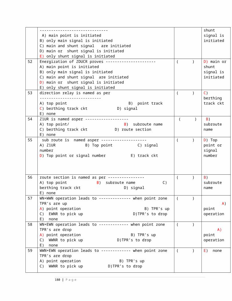
CHAPTER 2
STATE TRUE or FALSE
1. Microlok -II is a 2 out of 3 system. ( )
(
F
)
2. In MICROLOK-II, Application software is
common for all stations.
( )
(
F
)
3. In MICROLOK-II, Executive software is
common for all stations.
( )
(
T
)
4. Microlok-II system is limited to 4-road
station only.
( )
(
F
)
5. In Microlok II, each card file capacity is 20
slots.
( )
(
T
)
6. Non-Vital I/O cards are required in
Microlok-II system only when the system is
( )
(
T
180 | P a g e
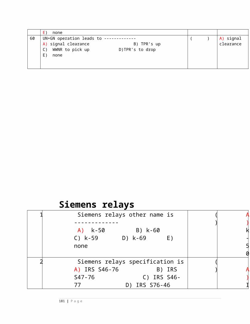
required to be interface with conventional
Control cum Indication Panel.
)
7. In Microlok-II system RS-485 ports are used
for vital interface.
( )
(
T
)
8. In Microlok-II system RS-232 ports are used
for Non-Vital data interface.
( )
(
T
)
9. In Microlok-II card file, maximum 20 nos. of
Input / Output interface cards can be
accommodated.
( )
(
F
)
10. In Microlok-II card file, CPU card occupies
the space of 2 slots.
( )
(
T
)
11. In Microlok-II card file, Power supply card
occupies the space of 1 slot.
( )
(
F
)
12. In Microlok-II CPU card is provided with
FLASH ROMs / EEPROMs for storing the
( )
(
T
181 | P a g e
executive and application software. )
13. In Microlok-II, each address select PCB
consists of 8 nos. of Jumpers.
( )
(
F
)
14. In Microlok-II, each address select PCB
jumper settings are unique and shall match
with the definition of cards in application
program.
( )
(
T
)
15. In Microlok-II card file, keying plugs
prevents plugging of wrong type of card.
( )
(
T
)
16. In Microlok-II, address select PCB is used to
address particular slot of the card file.
( )
(
T
)
182 | P a g e
17. The EEPROM PCB is placed on the 48 Pin
connector of the CPU card to store Site-
specific configuration data.
( )
(
T
)
18. Microlok II can be used as a Distributed
Interlocking System.
( )
(
T
)
19. Main Signalling Cable can be totally
eliminated with Microlok-II as a Distributed
Interlocking System.
( )
(
T
)
20. For a 4-road station with Microlok-II as a
Distributed Interlocking is costlier over
Microlok-II as a Centralised Interlocking
system.
( )
(
F
)
MULTIPLE CHOICE:
1. VCOR Relay has _____ _____ contacts.
A) 8F/B B) 4F/B C) 6F/B D)
2F/B
( ) C
)
6
183 | P a g e
F
/
B
2. VCOR Relay contact current rating is____ Amp
A) 1A B) 3A C) 5A D) 50mA
( ) B
)
3
A
3. In Microlok-II CPU card is provided with ______________
processor.
A) 68000 B) 8086 C) 68332
D)Intel Pentium
( ) C
)
6
8
3
3
2
4. In Microlok-II system, CPU card is provided with ______
no. of ports.
A)4 serial and 1 parallelB) 5 serialC) 4 parallel and 1 serialD) 5 parallel.
( ) B
)
5
s
e
r
i
a
184 | P a g e
l
5. In Microlok-II system, Input capacity of each Vital input
card is_______
A) 8 input B) 16 input C) 32 input D) None of the above
( ) B
)
1
6
i
n
p
u
t
6. In Microlok-II system, each Vital output card drives
_______no. of relays
A) 4 B) 8 C) 16 D) 32
( ) C
)
1
6
7. In Microlok-II system, each Non-vital input- output card
can be connected with maximum _____ no. of inputs and
_____ no. of outputs respectively.
A) 16 Inputs & 16 Outputs B) 8 Inputs & 8 OutputsC) 16 Inputs & 32 Outputs D) 32 Inputs & 32 Outputs
( ) D
)
3
2
I
n
p
185 | P a g e
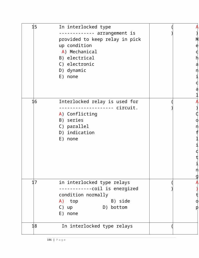
u
t
s
&
3
2
O
u
t
p
u
t
s
8. Non-vital Inputs are
A) Control Panel Push Buttons & Key contactsB) Track Circuits TPRs. Point DetectionC) VCOR indicationD) None the above
( ) A
)
C
o
n
t
r
186 | P a g e
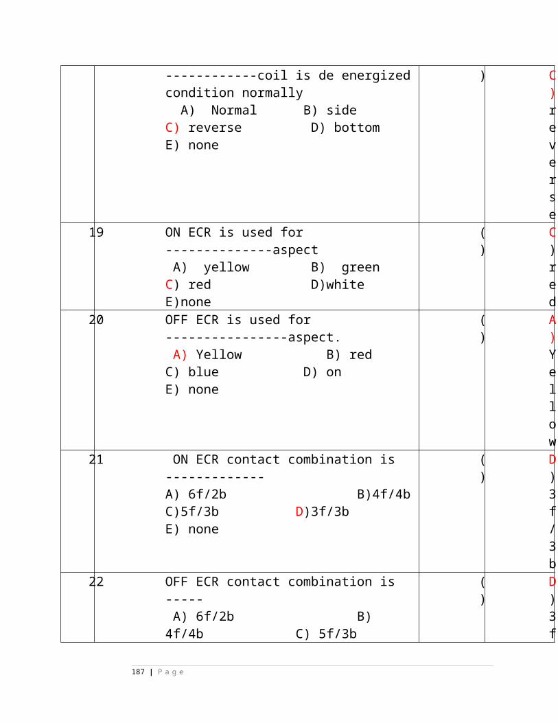
o
l
P
a
n
e
l
P
u
s
h
B
u
t
t
o
n
s
&
K
e
187 | P a g e
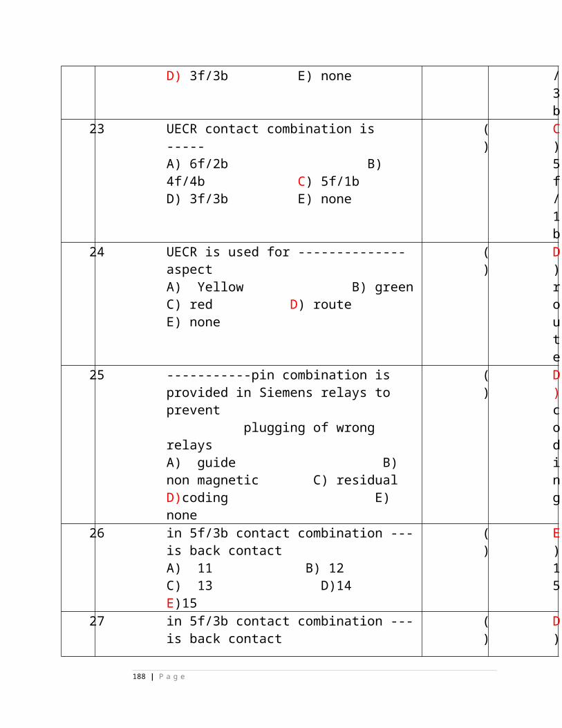
y
c
o
n
t
a
c
t
s
9. In the Card File the Power Supply Card is normally placed
in the slot no. _____
A) 1 B) 15 C) 16 D) 20
( ) C
)
1
6
10. In Microlok-II system, PC / Lab top loaded with
Maintenance tool software can to connect to Port
No._____ of CPU card.
A) 1 B) 3 C) 4 D)
5
( ) D
)
5
11. In Microlok-II, the 48 Pin Connector assembly is used for
__________
A) Vital Input boards only B) Vital Output boards onlyC) Vital Input and Output boards D) Non-vital I/O
( ) C
)
V
i
188 | P a g e
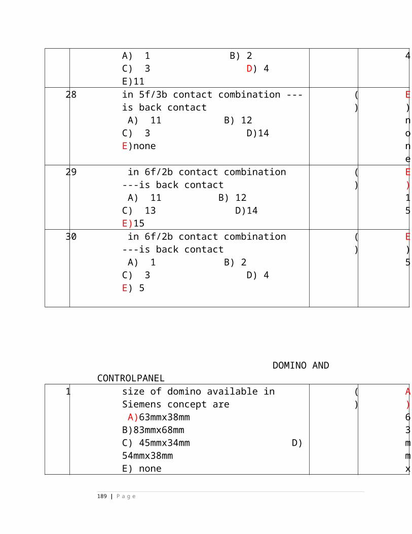
boards t
a
l
I
n
p
u
t
a
n
d
O
u
t
p
u
t
b
o
a
r
d
189 | P a g e
s
12. In Microlok-II, the 96 Pin connector assembly is used for
___________
A) Vital Input boards only B) Vital Output boards onlyC) Vital Input and Output boards D) Non-vital I/O boards
( ) D
)
N
o
n
-
v
i
t
a
l
I
/
O
b
o
a
r
d
s
13. To start design of MLK II based Interlocking system, ( ) D
190 | P a g e
Inputs required are ________
A) Approved Signal Interlocking Plan & Front Plate DrawingB) CT rack termination details.C) Details of any additional interlocking equipment to be interfaced with MLKII.D) All of these
)
A
l
l
o
f
t
h
e
s
e
14. In Microlok-II, each card file should be provided with
__________
A) Power Supply Card B) CPU cardC) VCOR D) All of these
( ) D
)
A
l
l
o
f
t
h
e
s
e
191 | P a g e
15. In Microlok-II, Application Program ‘ * ‘ symbol is used
for _______
A) SERIES B) PARALLEL
C) BACK CONTACT D) BIT SEPERATION
( ) A
)
S
E
R
I
E
S
16. In Microlok-II, Application Program ‘+ ‘ symbol is used
for _______
A) SERIES B) PARALLEL C) BACK CONTACT D) BIT SEPERATION
( ) B
)
P
A
R
A
L
L
E
L
17. In Microlok-II, Application Program ‘ , ‘ symbol is used for _______ A) SERIES B) PARALLEL C) BACK CONTACT D) BIT SEPERATION
( )D) BIT SEPERATION
18. In Microlok-II, Application Program ‘ ( ‘ symbol is used ( ) C
192 | P a g e
for _______
A) SERIES
B) PARALLEL
C) START OF PARALLEL PATH
D) END OF PARALLEL PATH
)
S
T
A
R
T
O
F
P
A
R
A
L
L
E
L
P
A
T
H
193 | P a g e
19. In Microlok-II, Application Program ‘ ) ‘ symbol is used
for _______
A) SERIES B) PARALLEL C) START OF PARALLEL PATH D) END OF PARALLEL PATH
( ) D
)
E
N
D
O
F
P
A
R
A
L
L
E
L
P
A
T
H
20.In Microlok-II, Application Program ‘ ; ‘ symbol is used
( ) D
194 | P a g e
for _______
A) SERIES
B) PARALLEL
C) END OF PARALLEL PATH
D) END OF STATEMENT/ SECTION
)
E
N
D
O
F
S
T
A
T
E
M
E
N
T
/
S
E
C
T
I
195 | P a g e
O
N
21. In case of Distributed Interlocking system _________________ is / are required to be used in place of Main Signalling Copper Cable between Relay/Equipment Room and Location Boxes/ Goomties. A) Object Controllers B) Optical Fiber CableC) both A & B D) None of these
( ) C
)
b
o
t
h
A
&
B
196 | P a g e
.
CHAPTER 3
STATE TRUE or FALSE
1. The SIMIS S basic system meets the Generic
CENELEC SIL3 safety standards.
( )
(
F
)
2. The SIMIS-S is following the coded mono
processing as TWO 1-out-of-1 processors in
standby configuration.
( )
(
T
)
3. In SIMIS S System, Reaction time of less than
1.5 seconds for showing a restrictive aspect
after a hazardous event occurs.
( )
(
T
)
4. SIMIS S System behavior is Fail-safe, if
failures occur within the system or the
operating modules
( )
(
T
)
5. In SIMIS S System, RS-232 protocol is used. ( )
(
F
197 | P a g e
)
6. PROFIBUS Protocol means Process Field Bus
Protocol.
( )
(
T
)
7. PROFIBUS protocol includes fault detection,
because of safety reasons no correction
procedure is implemented.
( )
(
T
)
8. In PROFIBUS protocol, if a telegram is
detected as false this telegram is send again.
( )
(
T
)
9. In SIMIS S System, Digital Input Modules
(Vital) and Digital output Modules (Vital)
are provided with hot swapping
feature.
( )
(
T
)
10. In SIMIS S System, Provides Interface
between the profibus and I/O modules in an
Electronic Terminal station.
( )
(
T
)
198 | P a g e
MULTIPLE CHOICE:
1. Maximum length, for which PROFIBUS
with copper cable can be used, without
repeater is _____
A) 100m B) 200m C) 500mD)1000m
(
)
B)
200m
2. Maximum length of PROFIBUS with
Optical Fiber Cable is _____
A) 1KMB) 5KMC) 10KM D)15KM
(
)
D)15KM
3. In SIMIS S System, the address switch is a
_____position dipswitch to identify the
correct Input / output card by the
processor. ( C )
A) 6 B) 8 C) 10D)16
(
)
C) 10
4. In SIMIS S System, Input capacity of each
Digital Input Module (Vital) is
(
)
C) 4
199 | P a g e
A) 16 B) 8 C) 4D)32
5. In SIMIS S System, each Digital Output
Module (Vital) drives _____ no. of relays.
A) 32 B) 16 C) 8D)4
(
)
D)4
6. In SIMIS S System, Rated input voltage of
Digital Input Module (Vital) is _____
A) 12V DC B) 24V DC
C) 60V DC D)110V AC
(
)
B) 24V
DC
7. In SIMIS S System, Rated output voltage
of Digital output Module (Vital) is _____
A) 12V DC B) 24V DC
C) 60V DC D)110V AC
(
)
B) 24V
DC
8. In SIMIS S System, each Electronic
Terminal Station shall be provided
with__________
A) Interface moduleB) Power moduleC) Digital Input and Output modules
D) all of these.
(
)
D) all of
these
1 --------------------- megger (insulation tester) shall be used to test insulation of signaling cable shall .
( )
a) 500 Volt DC
a) 500 Volt DC b) 500 Volt AC c) 100 Volt DC d) 100 Volt AC
200 | P a g e
2 __________ relay back contact shall be provided across DR back contact to ensure cascading arrangement in 3- aspect signal circuit.
( )
b) DECR
a) HECR b) DECR c) RECR d) HR
State TRUE or FALSE
1 The insulation resistance of the new Signaling cables should not be less than 10M ohms/ KM
( )
False
(True/False)2 Periodicity of cable meggering
for tail cables is once in a year.( )
False
(True/False)
S19 chapter no.1
1. The alphabet U is used in signaling for indicating (A) point (B) route (c) slot (D) track
( )
B
2. The alphabet T is used in signaling for indicating(A) track (B) signal (c)slot (D) train stop
( )
A
3. Symbol indicates in signaling. (A)Attention aspect control relay of signal No.5 (B) caution aspect controlling relay of sig.No.5 (c) clear aspect control relay of sig.No.5 (D) None
( )
C
4. Symbol indicates in signaling.
(A)ON aspect lamp of signal No.5
(B) caution aspect lamp of signal No.5
(c) Attention aspect lamp of signal No.5
(D) clear aspect lamp of signal No.5
( )
B
201 | P a g e
5 DR
5

5.
Symbol indicates the relay.
(A) Slow to release ( B) Slow to pick up (C) AC immunized (D) None
( )
C
6. The Alphabet ‘C’ used in signaling for (A) Checking (B) Clear (C) Caution (D) None
( )
A
7. above line indicates(A) Arm (B) Back (C) Front (D) None
( )
C
SIGNALLING RELAYS CHAPTER NO: 2
1. Relays which are connected directly to track are called as :(A) Line Relays (B) Track Relays(C) Polarized Relays (D) None
( )
B
2. The Relays which close same set of contacts when energized with normal polarity or reverse polarity supply are known as :(A) Polarized relays (B) DC Neutral relays(C) None (D) Vital relays
( )
B
3. The relays which have contacts with atleast one non-fusible contact(A) None (B) Vital(C) None proved type (D) Proved type
( )
C
4. An electromagnetic device which is used to convey information from one circuit toAnother circuit through a set of contacts is known as:(A) Economizer push button (B) Switch(C) Relays (D) None
( )
C
5. The relays which are used for controlling signal gears are known as:(A)Shelf type (B)Line relays(C) Vital relays (D) Non Vital relays
( )
C
6. Metal to metal contact relays are known as :(A) None Proved type (B) None Vital Type
(C) Proved Type (D) None
( )
C
202 | P a g e
~
CHAPTER NO:3
1. In shelf type relays contacts can be:(A) Dependent (B) Independent (C) Dependent & Independent (D) None
( )
C
2. In a relay Copper/Brass pins provided on the armature facing the magnet poles to maintain a small air-gap in its attracted position is known as :(A) Yoke (B)Contact (C) Residual pin (D) None
( )
C
3. Shelf type line works on :(A) 24 V DC (B) 12 V DC (C) 110 V DC (D) 12 V AC
( )
B
4. Front contact of shelf type relay has contact resistance of(A) 0.1 ohm (B) 0.5 ohm (C) 0.2 ohm (D) 10 ohm
( )
C
5. To avoid damage to contacts during transportation,the item provided in shelf type relays is known as :(A) Transportation screw (B) Residual pin(C) Coil terminal (D) None
( )
A
6. Shelf type track relay can be energized maximum upto :(A) 125% of P.U.V. (B) 300% of P.U.V (C) 250% of P.U.V. (D) 335% of P.U.V
( )
C
7. POH for track relays shelf type relay:(A) 15 Years (B) Not required (C) 10 Years (D) 20 Years
( )
C
8. POH for shelf type line relays(A) Not required (B) 10 Years(C) 15 Years (D) None
( )
C
9. AC immunization is achieved in shelf type AC immunized relays by(A) Magnetic shunt (B) Two copper slugs(C) Magnetic shunt & two copper slugs(D) None
( )
C
10. AC immunity of AC immunized shelf type line relay is(A) 100 V (B) 300 V(C) 50 V (D) None
( )
B
11. AC immunity of AC immunized track relay is ( D
203 | P a g e
(A) 100 V (B) 150 V(C) 300 V (D) 50 V
)
Chapter-41. The interchangeable contacts in Q-Series
relays A) A5,A6 B)B5,B6 C) D5,D6 D)None
( )
B
2. Plug in type line relays have POH of A)10yrs. B)No Overhauling C) 15 yrs. D) 10- 12 yrs.
( )
B
3. How many Code pins are used at a time in ‘Q’ Series relays.A) 2 B) 3 C) 4 D) 5
( )
D
4. All the contacts in ‘Q’ Series relays are A) Independent B) Dependent C) Independent & Dependent D) None of these
( )
A
5. The contacts used in ‘Q’ Series relays are A) M to M B) M to C C) M to M & M to C D) None of these
( )
B
6. QNN1 Consists of how many neutral relays.A) Only One B) Two C) Three D) None
( )
B
7. QNA1 relays are used in A)Relay room internal circuits B)All external circuitsC) All external circuits & internal relays in RR energized from external feed D) None
( )
C
8. QS3 relays have coil resistance of A) 1000ohms B) 100 Ohms C) 10 Ohms D) 10000 Ohms
( )
A
9. QS3 are used as A) TPR’s B) B) EVR & SUPR in Axle Counters C) C)Double line Block Inst. D) Single line Handle type Block Inst.
( )
B
10. QB3 has a permanent magnet nearerA)Heel piece side B) Armature Side C) In the Center D) None
( )
B
204 | P a g e
11. QB3 relays are used in A) Single line token less push button block inst.B) Double line block inst C) Diado InstrumentD) None
( )
A
12. QBCAI relay heavy duty contact can carry current upto A) 3A B) 30A C) 15A D) 20A
( )
B
13. QBAI relays are used in A) Single line token inst.B) Single line token less push button C) Diado Single line block InstrumentD) Double line Block Inst.
( )
C
14. QSPA1 relays are used in asA) TR B) TPR C) WLR D) None
( )
B
15. QSPA1 relays have pick up time of A) 540 – 600 m sec. B) 220 m sec. C) 150 m sec. D) 300 m sec.
( )
A
16. QBCA1 has a contact configuration of A) 8F/4B B) 2F heavy duty/ 4B C) 4F/4B D) None
( )
B
17. QL1 has a permanent magnet near to A) Armature B) Heel piece side C) At the center D) None
( )
B
18. How many coils are used in QL1 relay?A) only One B) Two coils C) Three D) None of these
( )
B
Chapter No.5Relays & Cables
1. How many code pins used in K-50 relaysA) 4 Nos. B) 2 Nos. C) 1 No. D) None
( )
B
2. How many maximum relays can be accommodated in a mini groupA) 30 Nos. B) 15 Nos. C) 2 Nos. D) 1 No.
( )
C
3. in a Siemen’s interlocked relay, how the latching is achieved.A) Magnetically B) Mechanically C) Electronically D) None
( )
B
205 | P a g e
4. Siemen’s relays work withA) 24 V DC B) 60 V DC C) 24 V AC D) 60 V AC
( )
B
5. K-50 relays are classified asA) K50-A, K50-B, K50-E type B) K50-C, K50-FC) All same D) None
( )
A
6. Siemen’s UECR relay contact configuration isA) 3F/ 3B B) 6F/2B C) 5F/1B D) None
( )
C
7. Siemen’s ON/ OFF ECR contact configuration isA) 3F/ 3B B) 5F/1B C) 6F/2B D) 4F/4B
( )
A
8. for wiring of 4 minigroups, the maximum tagblock required isA) 100 Way B) 80 way C) 160 Way D) 200 Way
( )
C
9. Siemen’s relay contacts areA) Independent type B) Dependent typeC) Dependent type & Independent type D) None of these
( )
A
10. How many guide pins are used in Siemen’s relaysA) 4 Nos. B) 3 Nos. C) 2 Nos. D) None
( )
C
Chapter No.6
1. The purpose of ECR isA) Providing Cascading arrangementB) Red lamp protection & Signal aspect indication at the operating place.C) Controlling the signal in accordance with the aspect displayed on signal in advance.D) All A, B, C.
( )
D
2. I type current transformer method is generally used forA) Red lamp B) Yellow lamp C) Green Lamp D) None
( )
A
3. For picking up of Siemen’s UECR, the minimum no.of Route lamps required to glow isA) 2 Nos. B) 4 Nos. C) 3 Nos.
( )
C
206 | P a g e
D) 5 Nos.
Chapter No.7
1. Siemen’s motorized clockwork timer relay works with A) 24 V DC B) 110 V AC C) 24 V AC D) None
( )
B
2. Siemen’s motorized clockwork timer relay has contact configuration of A) One front & one back B) 2 front & 2 back C) 3front & 3 back D) None
( )
A
3. QJ1 is used for A) Track relay B) TPR C) Timer D) None
( )
C
Chapter No.8
1. QT 2 track relay is used inA) Non RE B) RE C) Non Re & RE D) None
( )
A
2. QT 2 has contact configuration of
A) 2F/2BB) 2F/1BC) 2F only D) 2B only
( )
B
3. QTA2 &QBAT are used inA) Non RE only B) Non RE C) RE only D) None
( )
C
4. QBAT has contact configuration ofA)2F only B) 2B only C) 2F/2B D) None
( )
C
5. The AC immunity of QBAT isA) 50 V B) 80 V C) 90 V D) None
( )
B
6. The AC immunity of QTA2 isA) 80 V B) 90 V C) 50 V AC D) None
( )
C
7. The repeater relay used in relay room when QTA2/QBAT is used as TR.A) QB3 B) QNA1 C) QSPA1 D) QBCA1
( )
C
8. Back contact available in QTA2/QT2 is used for
(
A
207 | P a g e
A) Cross Protection B) Double cuttingC) Cross Protection & Double cutting D) None
)
CHAPTER NO-9
1. Siemens thermo flasher unit is used for(A) To create flashing of indication lamps on panel when
needed.(B) (B) To take photos(C) For arc wilding(D) (D) None
( )
A
2. Siemens thermo flasher works with(A)12 V DC/AC (B) 110 V AC(C) 220 V AC (D) All A,B,C,D
( )
D
3. What is flashing frequency of siemens thermo flasher unit ?(A) 120/mnt (B) 60/mnt(C)90/mnt (D) None
( )
B
CHAPTER NO-10
SLOW ACTING RELAYS
1 Slow to release arrangement in relays is created by
(A) Connecting a resistance across relay R1,R2.
(B) Connecting a condenser across relay R1,R2.
(C) A resistance & a condenser in series are connected across relay R1,R2.
(D) None.
( )
C
CHAPTER NO-11
1. When DC polarized relay is energized with
normal polarity +Ve on R1 and –Ve On
R2, the contact made is
( )
D
208 | P a g e
(A) No contact made (B) Front contact (C) Back contact (D) Normal contact
2. When DC polarized relay is energized with reverse polarity i.e; -Ve on R1 and +Ve on R2, the contact made is
(A) Normal contact (B) No contact (C) Back contact (D) Reverse contact
( )
D
3. When DC Polarized relay is in de-energized condition, the contact made is called
(A) Front contact (B) Back contact (C) No contact made (D) None of these
( )
C
CHAPTER NO-12
1. Generally what cable is used for Q-series relay wiringA) 16 Strand 0.2 mm flexible wire B) 0.6 mm Copper single strand C)
D)
( )
A
2. Generally outdoor cables numbering starts with -----conductor as No.1 and ends with ---------------conductor at each layer.A) Yellow, Blue B) Blue, Yellow C) Red, Blue
D) None
( )
B
3. No spare conductors required to left in case total number of conductors used is A) 12C B) 30C C) Three or less D)None
( )
C
4. The Megger used for testing Signalling cables is A) 110 Volts DC Megger B) 200 Volts DC MeggerC) 500 Volts DC Megger D) None
( )
C
Sl. No.
Question ( )
Answer
209 | P a g e
1. When RKT key is locked in condition then -------------------contact/s is/are in make condition a) 1&2 b) 3&4 c) 3&5 d) a&b
( )
d) a&b
2. When RKT key is out then ----------------- contact/s is/are in open condition a) 1&2 b) 3&4 c) 3&5 d) all
( )
3. Normal working voltage of RKT is ---------------------a) 3.75 DC volt b) 3.75 volt DC plus line drop c) 10 volt DC d) 12 volt DC
( )
b) 3.75 volt DC plus line drop
4. The maximum stroke of single wire lever lock is ---------------mm.a) 150 b) 200 c) 100
d) 45
( )
b) 200
5. YSR relay ensures ---------------------------- featurea) One slot one train b) one signal one train c) run trough d) a&b
( )
a) One slot one train
State True or False
Sl. No.
Question ( ) Answer
1. Electric lever lock is used where mechanical control on a electrical equipment is required. (True/False)
( )False
2. Maximum THREE slides can be placed in the EPD. (True/False)
( ) False
3. C and D detection slides of EPD are not inter-changeable where as siemens point machine are inter-changeable.(True/False)
( ) False
4. When in and out type of FPL is used then A type lock slid shall be used in EPD.(True/False)
( )
5. When in and out type of FPL is used then B type lock slid shall be used in EPD.(True/False)
( )False
6. When RKT key is to be transmitted then 1,2 & 3,5 contacts are in make condition. (True/False)
( )
Sl. No.
Question ( )
Answer
1 The stroke of siemens point machine is ----------------------mm.
a) 140
( )
c) 143
210 | P a g e
b) 150
c) 143
d) 2202 In signal machine
hold OFF mechanism is initially pick through -------------- a) Pick up coil
b) hold off coil c) diode & resistance d) a&b both
( )
a) Pick up coil
3 Feed to signal machine motor is control through ----------------a) K contact
b) H contactc) resistance
d) a&b both
( )
a) K contact
4 Normal position of H and k contact of signal machine is -------------a) K make & H open
b) K make & H makec) K open & H open
d) K open & H make
( )
b) K make & H make
5 Locking provided in GRS 5E point machine ---------------- type.a) Rotary
b) straight trough
c) in
( )
c) in & out
211 | P a g e
& out d) clamp type
6 When point is set and lock in normal then ------------------ makes.a) RC contact
b) NC contact c) ND contact
d) a&c both
( )
d) a&c both
7 Locking of switches provided in siemens point and IRS machine is/are ------------------ type.a) Combine
b) individual
c) clamp d) a&b both
( )
a) Combine
8 Simultaneous power & manual operation of point machine is prevented by-----------------a) Crank handle cut out contact b) locking of crank handle c) ward & feather on crank handled) a&b both
( )
a) Crank handle cut out contact
9 Maximum -------------------number of slides can be used in electrical point detector.a) 3 b) 4c) 2
( )
b) 4
212 | P a g e
d) 6 Various detection & control contact
10 available in IRS/ siemens point machine are ------------------.
a) 2 Control &2 detection b) 4 control &4 detection
c) 3 control &3 detection d) 8 control &8 detection
( )
b) 4 control &4 detection
11 Various detection contact available in IRS/ siemens point machine are -----------------
a) 1/1a , 2/2a 5/5a & 6/6a b) 1/1a , 2/2a 3/3a & 4/4a
c) 3/3a , 4/4a 7/7a & 8/8a d) 1/1a , 3/3a 5/5a & 6/6a
( )
c) 3/3a , 4/4a 7/7a & 8/8a
12 ------------------------ snubbing arrangement is provided in IRS/ siemens point machine
a) electrical b) mechanical
c) No d) a & b
( )
b) mechanical
13 ------------------------ snubbing arrangement is provided in GRS5E point machinea) Electrical b) mechanical c) No d) a & b
( )
a) Electrical
14 During obstruction test of machine operated point with 5mm test piece -----------a) Point shall not
( )
d) a ,b & c
213 | P a g e
lock b) friction clutch shall slip c) Detection contacts shall not make d) a ,b & c
15 Difference between normal working current and obstruction current shall not be more than -------------- Amps. a) 0.5 amps b) 5 amps c) 2.5 amps d) 10amps
( )
a) 0.5 amps
16 Power supply to point machine is control at----------------- level.a) Circuit b) battery c) machine d) a &c both
( )
d) a &c both
17 Crank handle contacts are provided to prevent simultaneous ---------------------- and -------------------- operation.a) Power b) manual c) hydraulic d) crowbar
( )
a) Power b) manual
18 Obstruction current shall not be more than -------------------- of normal working current.a) 2 times
( )
a) 2 times
214 | P a g e
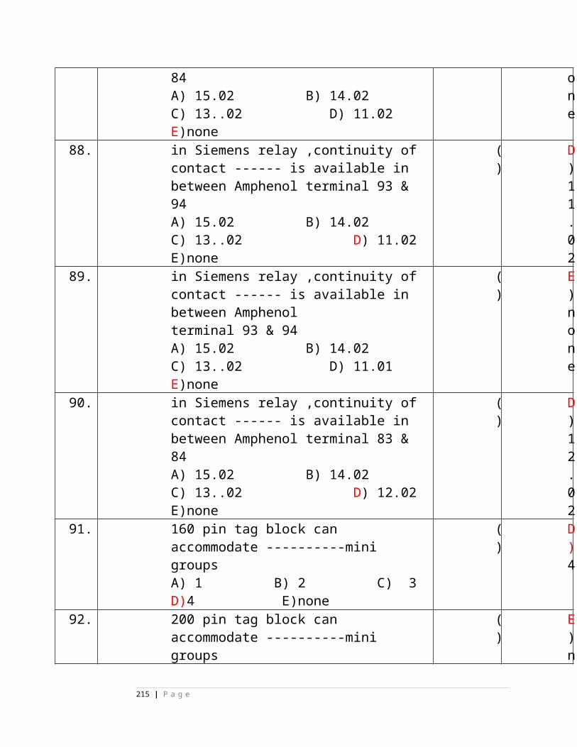
b) 0.5 timesc) 100 times d) 4 times
19 When electrical point detector is fixed on double slip then slides used is / are -------------.a) Detector slid C&D b) Detector slid A&B
c) Detector slid C, D & lock slid A d) a&b
( )
d) a&b
20 Detector slid C shall be connected to ------------------a) Nearest switch rail b) farthest switch rail c) Any one switch rail d) FPL
( )
a) Nearest switch rail
21 __________contact is connected across hold OFF coil of signal machine.a) H b) Kc) 0 to 5 band. d) 0 to 45 band
( )
a) H
Match the Following :
1. Friction clutch siemens (e ) a) electrical snubbing
2. Friction clutch signal machine (d ) b) unauthorized operation
3. Force drop arrangement (c ) c) mechanical/ magnetic
Stuck up4. Normal locking signal machine (b ) d) shock less holding of signal arm at OFF
5. diode and resistance (a ) e) mechanical snubbing
215 | P a g e
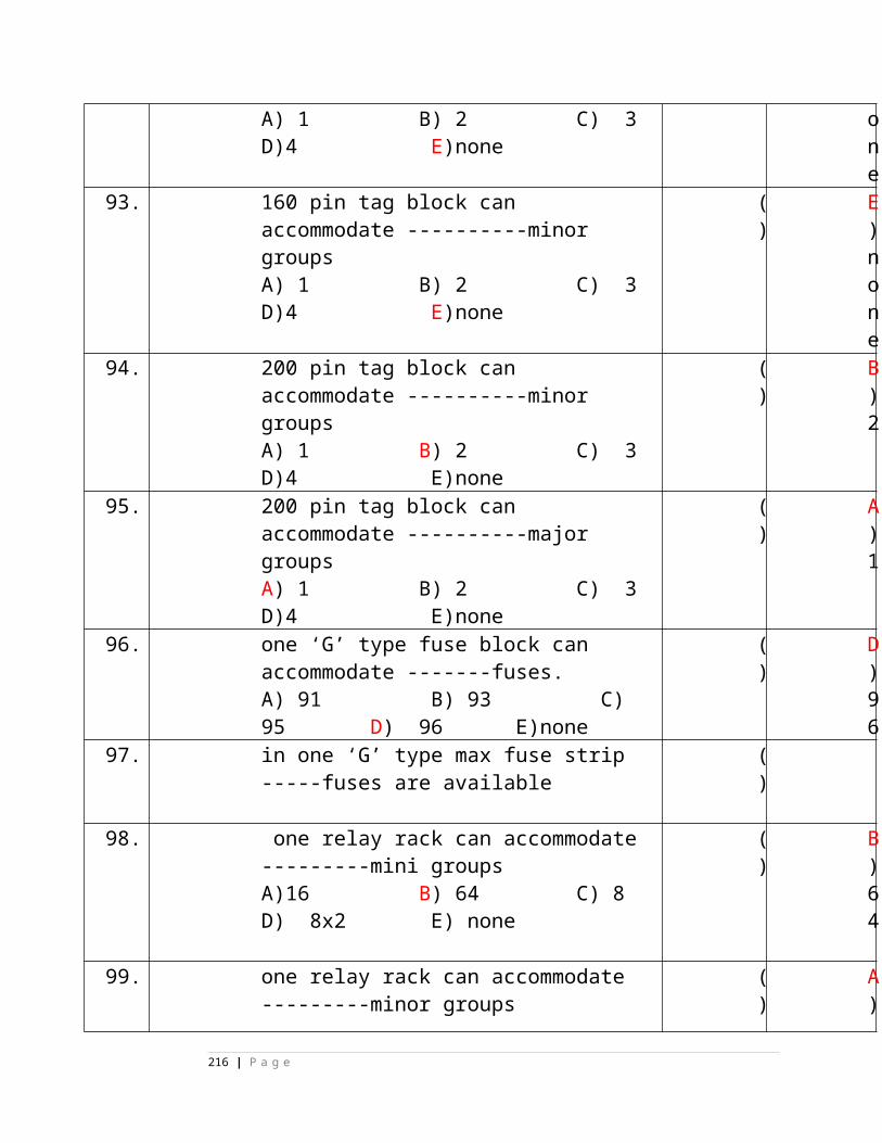
1 When point is set and lock in reveres then RC & RD contact will makes. (True/False)
( )
False
2 When point is not set and lock in normal then RC & NC contact will makes.(True/False)
( )
True
3 When point machine switching unit is taken out then RD & ND contact will makes.(True/False)
( )
True
4 Economizer contact in lever lock is for power saving.(True/False)
( )
True
5 H contact in signal machine is used to control feed to motor
( )
False
(True/False)6 Stroke of Siemens, IRS and GRS 5E
point machine is equal.(True/False)
( )
False
7 Function of top roller and bottom roller of Siemens point machine switching assembly is detect setting of switches and locking of switches respectively.(True/False)
( )
False
8 IRS point machine contains total four detection and control contacts.(True/False)
False
9 Snubbing in Siemens point machine is electrical type.(True/False)
( )
False
10 Siemens point machine friction clutch adjustment should be done at site.(True/False)
( )
False
11 When point is in mid position all control and detection contacts are in made position in Point machine.(True/False)
( )
False
216 | P a g e
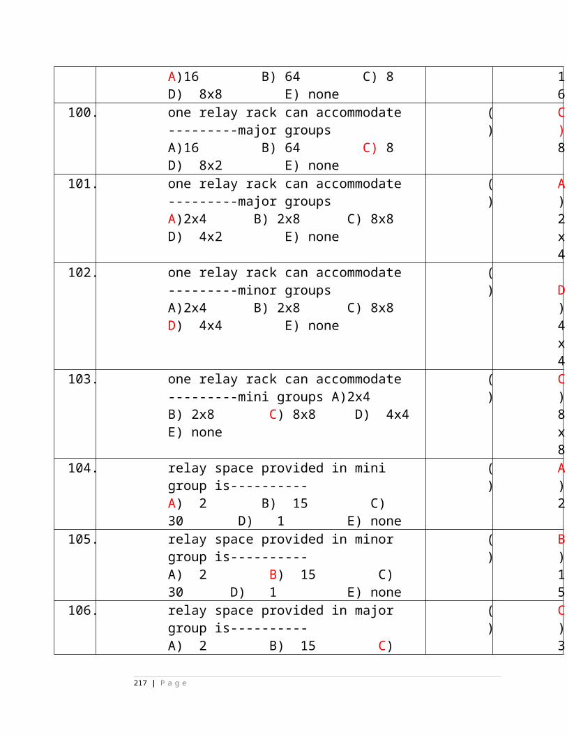
12 The normal condition of “K” and “H” contacts in Signal machine circuit is open.(True/False)
( )
False
13 In Electric detector, NWKR is wired across Normal Shunt contact(True/False)
( )
True
14 Maximum cores available in underground signaling cables are 37 cores
(True/False)
( )
True
15 The motor of IRS and Siemens point machine are interchangeable(True/False)
( )
False
16 Electrical parameter of The motor of IRS and Siemens point machine are same
(True/False)
( )
True
17 Thrust of The of IRS and Siemens point machine are same(True/False)
( )
False
CHOOSE THE CORRECT ANSWER
No.
Question ( )
Answer
1 “Authority to proceed” is given to -------------- to enter the block section with his traina) Guard b) Driver c) SM d) none
( )
b) Driver
2 Neales ball token Block Instrument is
( )
b) Singl
217 | P a g e
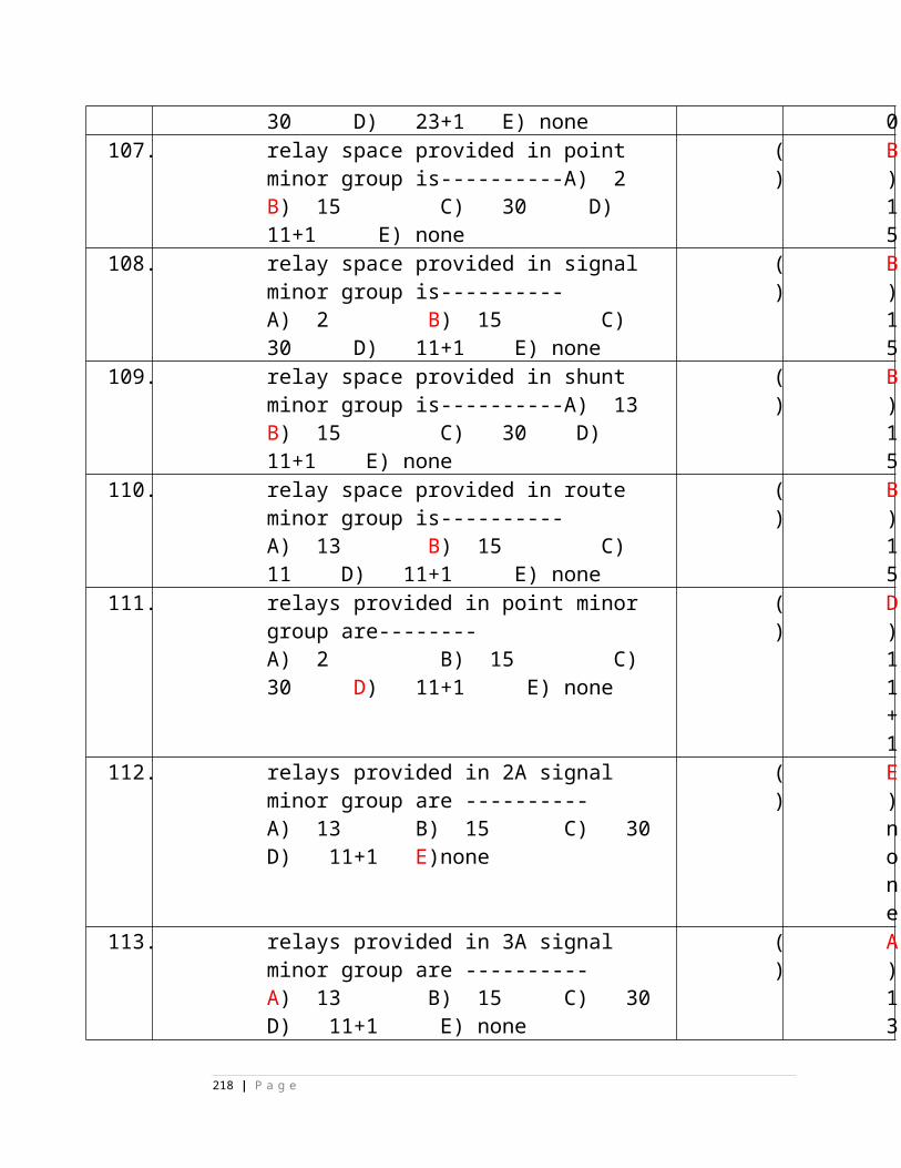
used for a) Double line section b) Single line section c) Automatic territory d) none of above
e line section
3 The POH of NBT Block instrument is a) 10 years b) 7 years c) 12 years d) 5 years
( )
a) 10 years
4 In double line Block working in Non- RE area we require a) 2 Lines only b) 3 Lines only c) 2 Line + separate Earth return d) 3 Lines + separate Earth return
( )
d) 3 Lines + separate Earth return
5 The Resistance of door lock coil is _________ in SGE DLBIa) 40 Ohms b) 50 Ohms c) 80 Ohms d) 160 Ohms
( )
b) 50 Ohms
6 Adequate distance meansa) 200 Mts b) 180 Mts c) Distance given to ensure safety d) Breaking distance + sighting distance
( )
c) Distance given to ensure safety
7 TGT lock coils picks up _________ no s of times while turning the handle to TGa) 1 b) 2 c) 3 d) 4
( )
b) 2
8 Tokens are classified into _____________________ no s of types a) 3
( )
c) 5
218 | P a g e
b) 4 c) 5 d) 6
9 The POH of DLBI is a) 7 year b) 12 years c) 10 years d) when SSE found necessary
( )
a) 7 year
10
Bell spring Assembly has _________ no of terminals in DLBI to use in Non – R.E AC a) 1 b) 2 c) 3 d) 4
( )
d) 4
11
When Bell plunger pressed _________ no of springs will make in DLBI SGE type Non – R.E ACa) 1 b) 2 c) 3 d) 4
( )
c) 3
12
When handle is turned to TOL the no of pairs of contacts that will make in DLBI byculla makea) 1 b) 2 c) 3 d) 4
( )
c) 3
13
TOL contact is DLBI will make in a) only in TOL Position b)TOL &line clearc) Line closed d) Only in Line clear
( )
a) only in TOL Position
14
Minimum no of Track circuit required for block release circuita) 1 b) 2 c) 3 d) 4
( )
b) 2
1 Voltage required to (
219 | P a g e
5 pick up PR relay is ________a)1.7 v b)2 v c)2.2 v d)1.5 v
)
16
Resistance of TCF/TGT relay is ____ ohmsa)150ohms b)148 ohms c)200 ohms d)136 oms
( )
b)148 ohms
17
Voltage required to pick up TCF/TGT relay isa)4.5 v b)5.5 v c)3.5 v d)6 v
( )
a)4.5 v
18
Current required to pick up TCF/TGT relay isa) 160ma b) 120ma c) 110ma d)100ma
( )
a) 160ma
19
No: of tokens that can be extracted at a time in NBT B/Ia) 4 b) 3 c) 2 d)1
( )
d)1
20
In a block station the minimum no: of block Instruments provided area) 4 b) 3 c) 2 d)1
( )
c) 2
MATCH THE FOLLOWING
1. LCPR (a) DLBI( )
2. TCF & TGT Coil Resistance (b) 148 Ohms ( )
220 | P a g e
3. PR Relay (c) 77 Ohms ( )
4. DLBI Line curent (d) 25mA( )
5. In coming trains (e) Bottom Indicator ()
6. Neales Ball Token Instrument (f) Spigot( )
7. SR1 & SR2 (g) LSS Clearance circuit ( )
8. Rest Contact (h) Neales Token Instrument( )
9. Butter fly type contact (j) DLBI SGE make ( )
10.POH of neales token inst (j) 10 years( )
11. POH of DLBI Podanur make (k) 7 years( )
No. Question ( ) Answer
1 Adequate Distance is the distance given as120mts to ensure safety (True/False)
( ) False
2 Block back is a message given to the driver to enter into block section (True/False)
( )False
3 The wring of Normal & Reverse polarity instrument are Identical in Neal’s Token Instrument (True/False)
( )False
4 Double line Block instrument should have 2 indicator only (True/False)
( )True
5 Double line Block instrument can be used for single line working (True/False)
( )False
221 | P a g e
6 PR in NBT does not require P.O.H (True/False)
( )False
7 In DLBI all the Block operation are done at sending end. (True/False)
( )False
8 Authority to proceed is given to the Guard of a special train (True/False)
( )False
9 Premature TOL is done in S/L Token Block Instrument (True/False)
( )False
10 Rest contact Breaks isolates PR with line Circuit (True/False)
( )True
11 Rest contact is dynamic is nature (True/False)
( )False
12 The object of providing Block Instrument is to prevent more than one train in a block section at a time (True/False)
( )True
13 Absolute Block working is to maintain space internal between two trains (True/False)
( )True
14 The Driver is a Absolute Block working should not enter into the Block section without proper Authority (True/False)
( )True
15 Token is handed over to the driver of a train as an authority to proceed (True/False)
( )True
16 At a time max no of tokens extracted from a pair of Block instruments are 2 No s (True/False)
( )False
17 To connect pair of NBT instrument we require 2 lines wire and earth return (True/False)
( )False
18 On a single line where trains work under absolute Block system every train in its progress from one block station to next shall be signalled over the block instruments(True/False)
( )True
19 Inserting the token into the block instrument indicate that the train is in his custody/train reached safely by the S.M (True/False)
( )True
20 I R S Drg No for Neal’s ball token instruments is SA 20701/M (True/False)
( )True
21 Solid balls are used as tokens in NBT Instrument (True/False)
( )False
22 The groove cut in Balls of NBT Instrument is to easy carry (True/False)
( )False
222 | P a g e
23 Different hole configurations are provided to distinguish the token belonging to block instruments of different block section(True/False)
( )True
24 SM’s key when ‘out’ in NBT will mechanically lock the bottom (operating) handle and Top Handle only (True/False)
( )True
25 Top handle can only be locked in its position at 85 from the vertical (True/False)
( )True
26 SM’s key removed no incoming or out going bell beats (True/False)
( )False
27 We can turn the top handle upto a maximum of 180 when token is not inserted (True/False)
( )False
28 Top indicator is having only one indication i.e green (True/False)
( )False
29 LSS control key can extract only in TGT Position of B/H (True/False)
( )True
30 When tokens are available in the instrument it is possible to turn the block handle to TCF (True/False)
( )True
31 When tokens are available in the instrument it is possible to turn the block handle to TGT (True/False)
( )False
32 Safety catch allows declutching of commentator shaft from spring clutch shaft while turning the handle from line close to TCF/TGT (True/False)
( )False
33 Lubrication is done with Axle oil medium grade to IS: 1628 (True/False)
( ) True
34 Checking the polarity of NBT instruments is done by not less then superior grade (JE)(True/False)
( )True
35 Adequate Distance is the distance sufficient to ensure safety(True/False)
( )True
36 6 types no: of types of block workings are existing in Indian railways (True/False)
( )True
37 Resistance of PR relay is 77 ohms (True/False)
( )True
38 Resistance of Galvo relay is 150 ohms (True/False)
( )True
39 Current required to pick up Galvo relay is 20 ma (True/False)
( )True
223 | P a g e
40 Capacity of Tablet token block instrument is 36 no: (True/False)
( )False
41 commutater has three positions ( Normal,Reverse & center ) (True/False)
( )False
42 In normal position of commutater if plunger is pressed 1 &3 commutater spring contacts make (True/False)
( )False
43 For shunting in the Block section Block handle should be kept in TOL condition where shunting is in progress (True/False)
( )False
44 Block handle cannot be turned to TGT when there is no tokens in the Block instrument (True/False)
( )True
QUESTION BANK FOR FM HANDLE TYPE INSTRUMENT
1 The following are the carrier frequencies in FM Instrument a) 2700HZ or 1800HZ b) 65HZ or 85HZ c) 2000HZ or 2500HZ c) All of the above
( )
[ a ]
2 The codes required to turn the handle to TGT in FM Instrument a) + Ve b) Carrier modulated by 65HZ with +vec) Carried modulated by 65HZ d) Carrier modulated by 85HZ with +ve
( )
[ b ]
3 The codes required to turn to handle to TCF in FM Instrument a) +Ve b) Carrier modulated by 65HZ with +vec) Carrier modulated by 85HZ with +ve d) Carried modulated
( )
[ c ]
224 | P a g e
by 65HZ 4 The codes required to
turn the handle to line closed position in FM Instrument a) +Ve b) Carrier modulated by 65HZ with +vec) Carried modulated by 65HZ d) Carrier modulated by 85HZ with +ve
( )
[ d ]
5 The code that Transmits during TOL code Transmission a) +Ve b) Carrier modulated by 65HZ c) Carrier modulated by 85HZ with +ve d) Carrier modulated by 65HZ with +ve
( )
[ b ]
6 Time Release Indicator operated by the following relay in FM Instrument a) 1R b) 2R c) 3R d) None
( )
[ c ]
7 Normal cancellation performed with the following switch a) S1 b) S2 c) PB1 d) PB2
( )
[ a ]
8 To turn the handle to TGT the following relays are to be picked up apart from other selections in FM instrument. a) CR1 & CR2 b) CR2, NR & TRSRc) CR2 & NR d) CR2 & BLR
( )
[ b ]
9 Unauthorised operation is prevented by the following key.
( )
[ c ]
225 | P a g e
a) Shunt Key b) Maintenance Key c) SM’s Key d) None
10 ‘One Train one line clear’ principle complained by the following relay in FM instrument.a) 2R b) TRSR c) 3R d) PBPR
( )
[ b ]
11 The following is the line relay in FM Instrument. a) PBPR b) TOLR c) NR d) CR1
( )
[ c ]
12 The following is the line relay in FM Instrument. a) PBPR b) BLR c) TOLR d) CR2
( )
[ b ]
13 3R used for the following purpose in FM Instrument
a) rain complete arrival b) Push back normalisation c) To operate time release indicator d) None of the above
( )
[ c ]
14 Which of the following is telephone relay. a) TER b) TEPR c) TELR d) TOLR
( )
[ c ]
15 To pick up CR2 the following Frequency is required. a) 65HZ b) 85HZ c) None of the above d) All of the above
( )
[ a ]
16 Which of the following is irrelevant to time release indicator in FM Instrument. a) 3R b) Free c) S1 d) S2
( )
[ d ]
226 | P a g e

17 CR1 not to be picked up for
a) Line closed to TCFb) TCF to line closed c) Line closed to TGT d) TGT to line closed
( )
[ c ]
18 CR2 to be picked up for
a) Line closed to TCFb) TCF to line closed c) Line closed to TGT d) TGT to line closed
( )
[ c ]
19 CR1 will not be help full in the following operation a) N to R b) R to N c) N to L d) L to N
( )
[ c ]
20 The following is not a power supply arrangement with regard to Block Instrument. a) Line battery b) Local battery c) External battery d) Internal battery
( )
[ d ]
21 Which of the following is relevant regarding AC RE area with respect to Block instrumenta) Block Filter unit b) Block Bell Equipment c) Isolation Transformer d) All of the above
( )
[ d ]
22 Which of the following is irrelevant to Time Release Indicator a) 3R b) S1 c) Free d) S2
( )
[ d ]
23 TRSR is a) Slow to Pick up b) Slow to Release c) None of the above d) All of the above
( )
[ b ]
227 | P a g e
24 TOLR is a) Slow to Pick up b) Slow to Release c) None of the above d) All of the above
( )
[ b ]
25 To turn the handle to TGT, which of the following frequencies are relevant a) 65HZ b) 85HZ c) None of the above d) All of the above
( )
[ a ]
True or False 1 Galvanoscope Indicates
incoming and outgoing DC currents. (True/False)
( )
(T)
2 Galvanoscope Indicates only outgoing DC current in FM instrument (True/False)
( )
(F)
3 Time Release Indicator operated during cancellation of line clear (True/False)
( )
(T)
4 Time Release Indicator operated during push back normalisation of the Block Instrument (True/False)
( )
(F)
5 Time Release indicator displays green with locked and changes to white with free when operated. True/False
( )
(F)
6 Switch S2 is used for cancellation of line clear True/False
( )
(F)
7 Switch S1 is used for ( (F)
228 | P a g e
push back normalization of the Instrument True/False
)
8 Switch S2 is used for push back normalization of the Instrument True/False
( )
(T)
9 The modulating frequencies are common for all Instruments(True/False)
( )
(T)
10. TOL indicator normally displays a white indication(True/False)
( )
(T)
11. TOL indicator displays red indication with ‘train on line’ before the train enter into block section(True/False)
( )
(F)
12. PB1 used to transmit DC Pulses for exchanging bell code signals(True/False)
( )
(T)
13. PB2 is a push button used in conjunction with PB1 to transmit frequency modulated code(True/False)
( )
(T)
14. Movement of the handle to TCF, TGT and back to normal position from TCF or TGT is controlled by a electrical lock(True/False)
( )
(T)
15. For turning the handle to TGT the lock is initially energises at X position but gets force dropped before X’ and it attracts at X’ position for further movement to TGT
(True/False)
( )
(T)
16. Check locking is provided to ensure the conscious co-operation of the operator at the other end(True/False)
( )
(T)
17. Check locking is effective while turning the handle fromTGT to Normal(True/False)
( )
(F)
18. Block handle assembly consist of 24 sets of spring contacts actuated during the cause of handle operation(True/False)
( )
(T)
229 | P a g e
19. Buzzer BZ1 operates when in a train enters block section(True/False)
( )
(T)
20. Buzzer BZ1 operates when a train clears the block section(True/False)
( )
(F)
21. BZ2 operated when a train clears the block section(True/False)
( )
(T)
22. BZ2 operated when a train enter the block section(True/False)
( )
(F)
23. SM’s key when removed the Instrument is inoperative for all functions(True/False)
( )
(F)
24. SM’s key when removed it is possible for the reception of bell codesignal or reception of transmission of TOL code(True/False)
( )
(T)
25. Shunt key can be removed only in line closed or TGT position(True/False)
( )
(T)
26. Shunt key can be removed in TCF position(True/False)
( )
(F)
27. Shunt key cannot be removed in TCF position(True/False)
( )
(T)
28. If the shunt key is removed the Instrument handle in locked mechanically(True/False)
( )
(T)
29. If the shunt key is removed the instrument handle is locked electrically(True/False)
( )
(F)
30. Insertion and extraction of shunt key can be done with out SM’s key in the Instrument(True/False)
( )
(F)
31. Transmitter gives a FM output when the DC feed us connected to it by different selection
(True/False)
( ) (T)
32. The modulating frequency is selected by the transmitter according tothe condition of the Block Instrument
( ) (T)
230 | P a g e
(True/False)33. Receiver gives DC output for energising
either CR1 or CR2 irrespective of the modulating frequency of the code received(True/False)
( )
(F)
34. The receiver is switched on when the DC feed is connected through the relevant selections(True/False)
( )
(T)
35. Level adjustment switch is a three position switch associates with the Receiver(True/False)
( ) (T)
36. The level of the signal output of the transmitter can be adjusted by level adjustment switch(True/False)
( ) (T)
37. Attenuator associates with the transmitter(True/False)
( ) (F)
38. Attenuator can be set to introduce the required db loss on the received signal(True/False)
( ) (T)
39. PBPR energised only when PB2 are pressed(True/False)
( )
(F)
40. PBPR energised when PB1 is pressed when TOLR relay is energised with Block handle in ‘R’ position(True/False)
( ) (T)
41. PBPR when energised connects to line battery –ve & +ve on L1 & L2 Respectively(True/False)
( ) (F)
42. PBPR when dropped connects NR relay to line (True/False)
( )
43. PBPR when dropped connects 24v to the transmitter (True/False)
( ) (F)
44. NR is a DC polar line Relay(True/False)
( )
(F)
45. NR energises when –ve is received on L1 and +ve to transmitter(True/False)
( ) (F)
231 | P a g e
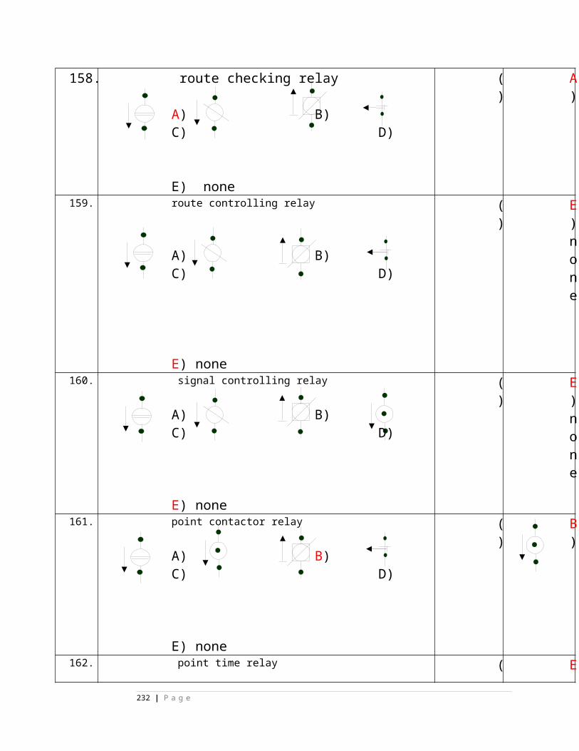
46. BLR is a DC Neutral line Relay(True/False)
( ) (F)
47. BLR energises when –ve is received is L1 and +ve on L2(True/False)
( ) (T)
48. TEPR is a DC polar Relay(True/False)
( ) (F)
49. TELR is energised when the pressed switch of hand micro telephoneis pressed(True/False)
( ) (T)
50. TELR connects to telephone current to the line through its back contact(True/False)
( ) (F)
51. TELR isolates transmitter and receiver from lines as they are connectedto lines through its back contact(True/False)
( ) (T)
52. 3R is line clear cancellation Relay(True/False) (T)
53. 3R picks up after about 120 seconds on operating switch S1 during cancellation of line clear (True/False)
(T)
54. TRSR sticks in the LX’ position of the operating handle (True/False)
( ) (T)
55. TRSR release when the train passes last vehicle Track circuit(True/False)
( ) (F)
56. TOLR picks up only before CR2 picks up at train receiving station(True/False)
( ) (F)
57. TOLR operated when the train occupies the first vehicle track circuit
when the operating handle is in TGT position.(True/False)
( )
(T)
58. TER operates when switch S1 is operated(True/False)
( )
(F)
59. TER operates when switch S1 is operated and LSS controls Normalised(True/False)
( )
(T)
60. CR1 picks up when a code of 1800HZ or ( (T)
232 | P a g e
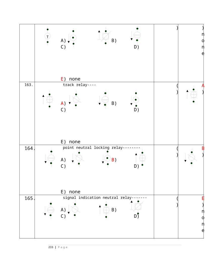
2700HZ modulated by85HZ is received from the distant station(True/False)
)
61. CR2 pick up when a code of 1800HZ or 2700HZ Modulated by 65HZ
is received from the distant station(True/False)
( )
(T)
62. CR2 energises TOLR in the other end instrument during TOL code
Transmission(True/False)
( ) (T)
63. TOLR indicator is of magnetic stick type(True/False)
( ) (T)
64. The Normal coil of TOLK is energised through back contact of TOLR(True/False)
( ) (F)
65. To Release coil of TOLK is energised through XX’ and YY’ contact
of Block handle(True/False)
( )
(F)
66. ASR and HSR are conflicting Relays in FM Instrument(True/False)
( )
(T)
67. ASR picks up when block handle is in TCF position with TRSR energised(True/False)
( ) (F)
68. The front contact of ASR controls the feed to the LSS(True/False)
( )
(T)
69. To pick up ASR, TRSR front contact is required (True/False)
( ) (T)
70. Bell circuit is having two parallel path one with BLR front contact
another with NR Back contact(True/False)
( )
(F)
71. Back contacts of CR1 and CR2 relays have been proved toensure that ‘PBPR’ relay will not be energised while receiving modulated frequencies(True/False)
( )
(T)
72. To Ensure that relays NR and BLR are not picked up simultaneously
( )
(F)
233 | P a g e
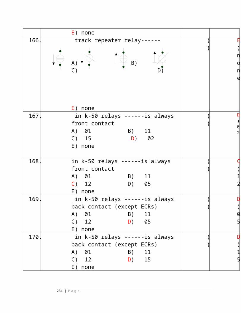
front contact of NR relay is proved in BLR circuit(True/False)
73. Back contact of ‘PBPR’ and front contact of PBPR are proved in
DC feed circuit of TX and RX respectively(True/False)
( )
(F)
74. Front contacts of CR1 & CR2 have been proved into DC feed circuit
for transmit to ensure that no code except the code of bell signals can be generated unless the code relays are de-energised(True/False)
( )
(F)
76. Since TOL to be transmitted automatically, front contact of PBPR is not provided in DC feed circuit to the Transmitter(True/False)
( )
(T)
77. Receiver to be in readiness to receive the TOL code the DC feed circuit is taken via 2R relay block contact with the block handle at R position(True/False)
( )
(T)
78. Press contact of the PB2 in the DC feed circuit of the transmitter prevent DC feed to TX while acknowledging TOL code(True/False)
( )
(T)
79. Block handle contact BX and DY are included in the DC feed circuitto the receiver minimises the battery consumptions(True/False)
( )
(T)
80. SM’s key contact has not been proved in the DC feed circuit of
Transmitter to ensure that the TOL indicator will display immediately to block section is occupies irrespective of the position of SM’s key(True/False)
( )
(T)
( )
81. Cross protector to the lock magnet coil ( (F)
234 | P a g e
is given through CR1 and CR2 front contact(True/False)
)
82. TX and RX are connected to line through the back contact of ‘TELR
to ensure that during conversation on telephone no code in transmitted or received by the TX & RX respectively at either end(True/False)
( )
(T)
83. The telephone set is connected to the lines through to front contact of TELR(True/False)
( )
(T)
84. The TELR feed is taken through to back contact of CR1 & CR2 andTOLR to ensure that during transmission and reception of TOL code to telephone is disconnected(True/False)
( )
(T)
85. The front contact of TOLR is included in the TELR pick up circuit to ensure that the telephone circuit is disconnected the movement TOLR picks up to transmitter or receive TOL code(True/False)
( )
(F)
86. TOLR is made slow to release since its energising circuit is through the front contact of TRSR and stick circuit is through back contact of(True/False)
( )
(T)
87. TRSR is made slow to release to provide the conditions required forthe energises circuit of TOLR in which the front contact of TRSR and back contact of FVTPR included(True/False)
( )
(T)
88. Switch S1 Reverse contact has been included in the ASR circuit(True/False)
( ) (F)
89. In Non RE area FM signal super imposed on to same pair of line
wires of DC circuit(True/False)
( ) (T)
235 | P a g e
90. In RE area it is worded on a pair of conductor of pet quad of main
telecom cable and to Dc circuit workers on two phantoms derivedfrom the pet quad(True/False)
( )
(T)
91. In AC RE area since a physical pair is used for FM signal and a derived phantoms is used for DC the choke CH1 is very essential
(True/False)
( )
(F)
Matching1. Galvanoscope coil Resistance a) 18.2 ( )2. Time Release Indicator b) 120 Sec ( )3. Resistance of the
time Release Indicator coil
c) 200 Ohms ( )
4. To Turn B/H to TCF d) Lock to be energised at Y Position
( )
5. To turn B/H to line closed from TCF or TGT
e) Lock to be energised at D & B respectively
( )
6. Locking effective at ‘X’ f) Check Locking ( )7. B/H assembly g) 24 sets of spring
contacts( )
8. Single stroke bell h) Coil Resistance 310 Ohms & 70mA
( )
9. Carrier Frequency i) 1800HZ & 2700HZ ( )10.TELR Relay j) Coil Resistance 70
Ohms( )
11.Normal condition of signals and controller
k) 1R ( )
12.One Train one line clear l) TRSR ( )13.Train on line Relay m) TOLR ( )14.TER coil Resistance n) 50 Ohms ( )15.TOLR o) Two coils of 500
Ohms & 200 Ohms( )
16.CR1 & CR2 p) conflicting Relay ( )17.ASR & HSR q) external
conflicting Relay( )
18.DC –Ve to be sent on L1 r) For Exchange of Bell code signals
( )
236 | P a g e
19.Filter unit s) AC RE area ( )20.Free indicator t) Green back
ground( )
21.TOL u) Red Back ground ( )22.Locked v) white Back ground ( )23.Galvanoscope w) Polarised Indicator ( )24.Shunt Key x) Locked Block Handle
Mechanically( )
25.Bell coil unit y) NR & BLR front contact In Parallel ( )
QUESTION BANK FOR S23 PUSH BUTTON
1. To obtain the full advantage of Tokenless block working push button type have been evolved(True/False)
(T)
2. A pair of push button instrument are connected with four line wires(True/False)
(F)
3. Push button instruments are purely relay interlocked(True/False)
(T)
4. Push button instruments are electro mechanical Instruments(True/False)
(F)
5. Pressing TGB and BCB at train sending station transmits ‘Train goingto ‘ to the instrument at the other end(True/False)
(F)
6. After the Instrument at the receiving end in set to TCF & TGT codeis transmitted back to train sending end(True/False)
(T)
7. When train arrives operation of push button BCB & TCB simultaneously at the receiving end reraly in transmission of the Line closed code to the train sending end instrument(True/False)
(T)
8. The user had to provide EKT instruments for shunt key and stop/catchsiding control key where required(True/False)
(T)
9. TOL or Free indication lit on establishment without the requirement
of BCB or panel lamp Button pressed(True/False)
(T)
237 | P a g e
10. The Non co-operative feature is destroyed by locking up of the instrument(True/False)
(F)
11. First step of operational code station with +ve in PB(True/False)
(F)
12. Code for bell is +ve in PB Instrument(True/False)
(T)
13. To cancel ‘Train going to’ condition before the train enter the blocksection BCB & LCB must be operated at both station concurrently(True/False)
(T)
14. Set the Block instrument to line closed when the train pushes back to thedispatching station BCB & LCB must be operated at sending station concurrently(True/False)
(F)
15. All operational codes are transmitted only when LCB or TGB is presses withBCB at the transmitting station(True/False)
(F)
16. ‘Train on line’ Buzzer operates only at the receiving station (True/False)
(T)
17. Train on line code is suppressed by the sending station by keeping the pressed TGB
(True/False)
(T)
18. SNR proves the Normal position of all the signals and their control levers/knobs pertaining to that block section(True/False)
(T)
19. Picking up of SNR indirectly proves that shunt key and slip/catch siding keys are out position(True/False)
(F)
20. SNR picks up by pressing BCB along with TGB/LCB buttons(True/False)
(T)
21. SNR picks up automatically on receipt of all 2nd functioned pulse and drops at the end of 3rd pulse(True/False)
(F)
22. Normal position of FVT & LVT are proved in SNR circuit(True/False)
(T)
23. For all functioned SNR relay working is a must(True/False)
(F)
24. Though feed to other relay from the external circuit is
238 | P a g e
available it does not pick up however SNR indication is available(True/False)
(T)
25. TAR picks up through external battery(True/False)
(T)
26. TAR de-latches to Normal through line battery once the instrument assumes to line closed position(True/False)
(F)
27. ASTR picks up once FVT is actuated (True/False)
(F)
28. Dropping of ASTR in TGT position initiates transmission of Automatic TOL code(True/False)
(T)
29. ASTR picks up and stock while initiating push back normalization (True/False)
(T)
30. Non Energization of this relay will not permit the instrument to changeto TGT even on receipt of answer back TGT code (True/False)
(T)
31. TCKR at transmitting and CRR relay at receiving end are in series through to line with the line battery at the transmitting end(True/False)
(T)
32. In the line circuit at the receiving end RCKR front contact is proves(True/False)
(F)
33. RCKR acts as a code pulse terminator(True/False)
(T)
34. Generator and transmission of a pulse is done at the transmitting end while the terminator of a pulse are ordered by the circuit at the receiving end(True/False)
(T)
35. RCKR prepares the instrument for automatic answer back(True/False)
(T)
36. CTR by its state of energization or deenergization decides whether the instrument is receiving or transmitting respectively(True/False)
(F)
37. CTR relay front contact the line battery to lien while its back contact connect
CRR(R)/CRR (R) to line(True/False)
(T)
239 | P a g e
38. LCCPR drops when line closed code is received from line(True/False)
(F)
39. Picking up to LCCPR enables to TGTR or TCFR to release and switches on CTR for answer back when necessary(True/False)
(T)
40. LCCPR allows line closed code transmission as an automatic reply code
only when to enquiry code is line closed code and _____________(True/False)
(T)
41. PTR & NTR are used respectively to connect –ve /+ve of the line battery on line at the transmitting instrument(True/False)
(F)
42. LR is the relay that is reacted on front by CRR(R) or TCKR while the instrument is receiving or transmitting respectively(True/False)
(T)
43. Zener Diode is provided across the condenser of 3CR relay to have a contact time delay irrespective of the voltage variation(True/False)
(T)
44. 1 CR os having toe branches one with TCKR and other with RDR respectively effective during transmission and reception of code(True/False)
(T)
45. PZR & NZR _____ the polarity of the front pulse of code that is received(True/False)
(F)
46. When the SM acknowledges the TOL code by pressing BCB to transmita bell code to TOLAR at the sending station __________ and causes
TOLTR drop to stop the transmission of TOL codes(True/False)
(T)
47. PCR picks up at the end that initiates line closed operation(True/False)
(T)
48. TGTR picks up on successful reception of TCF code and releases when line
closed code is received(True/False)
(T)
49. TCFR picks up when TCF code is received and releases on reception of line closed code(True/False)
(T)
50. ASCR picks up and locks the signal when cancellation is
240 | P a g e
initiated(True/False)
(T)
51. Front contact of ASR (True/False)
Matching the following 1. Push Button colour Black ( )2. Train Going to Button colour b) Green ( )3. Line closed Button colour c) white ( )4. cancelled Button d) Red ( )5. Panel lamp Button e) Yellow ( )6. Shunt key Button f) Blue ( )7. No drain circuit feature g) SNR ( )8. ASTR h) Repeate of FVTR ( )9. CRR I) Polarised Relay ( )10. TCKR J) Transmission o f code
checking Relay( )
11. RCKR k) Code reception checking Relay
( )
12. N2R l) Second -ve pulse receiving relay
( )
13. PCR m) Relay that changes pulse
( )
14. CAR n) Cancellation Relay ( )15. ASCR o) LSS control Relay ( )16. SCKR p) Low voltage
monitoring Relay ( )
17. ASR q) Advanced station Relay
( )
18. Q series Relay PBI r) 36 Relays ( )19. NV1 Relay PBI s) 4 Relays ( )20. Bell t) +Ve ( )
1 To set the Instrument to TGT the following Buttons are to be pressed at the train sending station
a) TGB b) BCBc) BCB & TGB simultaneouslyd) All the above
( )(c)
2 One of the following is TCF Code a) - + - b) - - + c) - - - d) - + +
( ) (a)
241 | P a g e
3 One of the following is TGT code a)- + - b) - - + c)- - - d)- + +
( ) (b)
4. One of the following is line closed code a)- + - b) - - + c)- - - d)- + +
( ) (d)
5. Shunt key cannot be extracted in a) TCF b) TG c) Line closed d) TGT – TOL
( ) (a)
6. One of the following is TOL code a) - + - b) - - + c)- - - d) - + +
( ) (c)
7. When the PB instrument is locked by the SM the following is possible
a) To set the instrument to TGTb) To initiate line closed codec) To send bell code d) To transmit receive the TOL code
( ) (d)
8. When the PB instrument is locked by the SM the following is not possible
a) Transmit TGT codea) TCF or line closed code b) Transmit answer back line closed code c) To initiate line closed code
( ) (d)
9. The following is not an external circuit Relay a) SNR b) ASTR c) TARd) RCKR
( ) (d)
10. External circuit Relays will not monitor the following condition
a) Normal position of Reception and dispatch signals and their controls
b) Entry/Occupation of Block section by a train c) Clearing of Block section by a traind) Normalization of the Block Instrument
( ) (d)
11. The following is irrelevant to TAR Relay in PB a) External Battery b) Local Battery c) Line Battery d) Magnetic latch
( ) (c)
12. The following Relays are picked up by line Battery a) TCKRb) CRRc) All of the above d) None of the above
( ) (c)
242 | P a g e
13. The following Relay energised by Local Battery a) TCKR b) SNR c) CRRd) RDR
( ) ( d)
14. The following Relay stores the first pulse of any code when it is –Ve
a) RCKRb) CTR c) RDR d) CTPR
( ) (c )
15. Picking up of CTR will not prove the following a) All reception and dispatch signals pertaining to an
Instrument are Normalb) No shunting is being carried out in the face of a trainc) SM is Keeping the required button in the pressed condition d) The conditions are not favourable for answering back
( ) (d)
16. The following is not a coding Relays a) 2 CR b) PCR c) 3CR d) 1CR
( ) (b)
17. The following Relays is not a magnetic latch Relay a) TGTRb) TCFT c) TOLTRd) TAR
( ) (c)
18 . Picking up of SHKR is not a pre-requisite for activation of
a) CTRb) TCFRc) PCRd) TGTR
( ) (c)
19. The following is not a button Relay a) TGTBR b) SCKRc) LCBRd) BCBR
( ) (b)
20 . The following power supplies is not required for PB Instrument
a) Local Batteryb) Internal Batteryc) Line Batteryd) External Battery
( ) (b)
243 | P a g e
TRACK CIRCUITS1 Train shunt Resistance (TSR) is directly proportional to the
Relay voltage.
True/False
( ( T)
2 Ballast resistance (RB) is directly proportional to the length of the Track circuit.
True/False
( ( F)
3 Dead section on the point zone shall not be more than 1.8 m (6’) for B.G.
True/False
( ( T)
4 The value of the regulating resistance used in the D.C track circuit in AC RE area is 0-30 (adjustable) True/False
( T)
5 Minimum permissible Ballast resistance of a D.C track circuit in Block section shall be 2 Ω/ K.M
True/False
( ( F)
6 Minimum permissible value of TSR for a D.C track circuit shall be 0.5 ohms.
True/False
( ( T)
7 Maximum length of DC Track Circuit in AC RE area using QBAT is 750 m with B type choke at both ends.
True/False
( ( T)
8 The maximum limit of voltage drop across DC track relay of QTA2 is up to 300% of its pick up value.
True/False
( ( T)
9 The total stray current as measured, shall not exceed 10 milliamps if the length of the track circuit is less than 100metres.
True/False
( ( T)
10 The total stray current as measured, shall not exceed 100 milliamps if the length of the track circuit is more than or equal to 100metres.
True/False
( ( T)
244 | P a g e
11 Stray voltage shall not be more than 100mv irrespective of length of track circuit.
True/False
( ( T)
12 The insert to insert resistance of a sleeper should not be less than 500 ohms
True/False
( ( T)
13 B type choke has impedance Z=120Ω and resistance = 3Ω.
True/False
( ( T)
14 Insulation Resistance Testing of Glued Joints is done with 100V DC Megger.
True/False
( ( T)
15 Insulation Resistance of a glued joint in Dry condition shall not be less than 25 MΩ when a meggering voltage of 100V DC is applied across the joint. True/False
( ( T)
16 Insulation Resistance of a glued joint in wet condition shall not be less than 3 KΩ.
True/False
( ( T)
17 The measured TSR value of a track circuit should be always higher than the minimum TSR of 0.5 ohms.
True/False
( ( T)
18 Minimum permissible ballast resistance in station yard is 2 Ω/Km
True/False
( (T )
19 Minimum permissible ballast resistance out side station yard is 1 Ω/Km
True/False
( ( F )
20 Track Relay used for track circuit length up to 100 m is 2.25 Ω
True/False
( ( F )
21 Track Relay used for Track Circuit length more than 100 m is 2.25 Ω
True/False
( ( T )
245 | P a g e
22 The minimum length of a DC track circuit is 2 rail lengths (26m)
True/False
( ( T )
23 Regulating resistance (Round Type) used in DC track circuit of Non-RE area is 0-15 Ω.
True/False
( ( T )
24 The DC Track Circuit Regulating Resistance can be made zero
True/False
( ( F )
25 Ballast Resistance is inversely proportional to Length of Track Circuit.
True/False
( ( T )
26 When TPR drops, it indicates that the Closed Track Circuit is not occupied by the train.
True/False
( ( F )
27 Transverse Bonds are provided between Positive Rails in DC Single Rail Track Circuit.
True/False
( ( F )
28 Transverse Bonds are provided between Negative Rails of adjacent DC single rail track circuits.
True/False
( ( T )
29 Rail Resistance is directly proportional to the length of The Track Circuit.
True/False
( ( T )
30 Rail Resistance shall not exceed 0.5 Ω/Km., if Track Circuit Length is more than 700 m.
True/False
( ( T )
31 Rail Resistance shall not exceed 1.5 Ω/Km., if Track Circuit Length is less than 700 m.
True/False
( ( T )
32 Under minimum Ballast Resistance condition, for the QBAT Track Relay, voltage across the track relay shall not be less than 125% of its Rated Pick UP Value.
True/False
( ( F )
246 | P a g e
33 Under minimum Ballast Resistance condition, voltage across the track relay shall not be less than 125% of its Rated Pick UP Value except for QBAT.
True/False
( ( T )
34 The insert-to-insert resistance of a PSC sleeper should be more than 500Ω for use in D.C track circuit.
True/False
( ( T)
35 When drop shunt test is done with 0.5ohm resistance the relay voltage should not be more than 85% of drop away voltage.
True/False
( ( T)
36 As per SEM the availability of GFN liners should be ensured up to 97% for proper working of DC track circuit.
True/False
( ( T )
AFTC
1 Where Ballast conditions are poor, AFTC of more than 450m length should be of the centre fed version.
True/False
( ) ( T )
2. Where Ballast conditions are poor, AFTC of less than 450m length shall be of the end fed version.
True/False
( ) ( T )
3. Siemens FTGS track circuits are not coded track circuits.
True/False
( ) ( F )
4. ‘S’ bonds are used where Siemens AFTC is followed by ALSTOM AFTC.
True/False
( ) ( F )
5. If ALSTOM AFTC is followed by ALSTOM AFTC, ‘S’ bonds can be used.
True/False
( ) ( T )
6. In SIEMENS AFTC, 12 different types of carrier frequencies are used.
( ) ( T )
247 | P a g e

True/False
7. In SIEMENS AFTC, data signal (modulating signal) is 8-bit pattern
True/False
( ) ( T )
8. In SIEMENS AFTC, 8 different types of data signals are available for each carrier frequency.
True/False
( ) ( F )
9. In SIEMENS AFTC, receiver-I card checks received signal amplitude and frequency
True/False
( ) ( T )
10. Receiver-I card of SIEMENS AFTC is a universal card.
True/False
( ) ( F)
11. Transmitter card of SIEMENS AFTC is a frequency dependent card i.e. separate card is required for each frequency.
True/False
( ) ( F )
12. Receiver-II card of SIEMENS AFTC is a universal card.
True/False
( ) ( T )
13. Demodulator card of SIEMENS AFTC is a universal card.
True/False
( ) ( T )
14. In SIEMENS AFTC, data verification is done by Receiver-II card
True/False
( ) ( T )
15. In SIEMENS AFTC, amplitude assessment is done in amplifier card.
True/False
( ) ( T )
16. FTGS-46 is suitable for short length track circuits.
True/False
( ) ( F )
17. FTGS-917 is suitable for long length track circuits.
True/False
( ) ( F )
248 | P a g e
18. FTGS-917 is suitable for short length Track circuits
True/False
( ) ( T )
19. SIEMES AFTC worked on MSK Principle
True/False
( ) ( F )
20. ‘TSR value in the track circuited portion of AFTC is 0.5Ώ
True/False
( ) ( T )
21. TSR value in the tuned zone portion of AFTC is 0.15 Ώ
True/False
( ) ( T )
22. Audio Frequency Track Circuit can be a Joint Less Track Circuit except in Point Zone Track Circuit.
True/False
( ) ( T )
23. Z’ bonds are used in the turned zone of SIEMENS AFTC.
True/False
( ) ( F )
24. ALSTOM AFTC worked on FSK principle
True/False
( ) ( F )
25. In ALSTOM AFTC, only three different types of data signal are available for each carrier frequency.True/False
( ) ( T )
26. DTC-24 is suitable for long length track circuits
True/False
( ) ( T )
TRACK CIRCUITS1. Maximum voltage of DC track relay(shelf type) should not
exceed -------- of its rated pick up voltage under maximum ballast resistance and maximum battery voltage.
2. Maximum voltage of DC track relay shall not be less than - - - - - of its rated pick up value under minimum ballast resistance and minimum battery voltage.
3. Maximum voltage of DC Q-Series track relay (QTA2/QT1)should
249 | P a g e
not exceed -------- of its rated pick up voltage under maximum ballast resistance and maximum battery voltage.
4. Voltage at track relay terminals with 0.5 ohm TSR should be less than 85% of its - - - - - - -- - - - - value.
5. The size of continuity bond wire is - - - - - - .
6. Overhauling period of a shelf type track relay- - - - - - - .
7. The DC resistance of B type choke is - - - - - - - .
8. AC impudence of B type choke is - - - - - .
9. Block joints are to be changed as whole once in a - - - - - - - .
10. Polarity of the supply to the adjacent track circuit is to be - - - - - -- - .
11. Minimum permissible TSR for DC track circuits is - - - - - -
12. The recommended rail resistance per Kilometre is not more than - - - - - .
13. The recommended ballast resistance per kilometre in station section is - - - - - .
14. The recommended ballast resistance per kilometre in Block section is - - - - - .
15. The clearance between bottom of the rail and ballast is - - - - - - .
16. The insulation resistance of glued joint in dry condition when 100VDC applied across the joint is- - - - - - - - .
17. The insulation resistance of glued joint in wet condition when 100VDC applied across the joint is- - - - - - - - .
18. Formula used to calculate the rail resistance - - -- - - - -.
19. Formula used to calculate the ballast resistance - - -- - - - -.
20. The coil resistance of QBAT relay is - - - - - - -
21. The percentage release of track relay is - - - - - - - .
22. The maximum excitation for DC Q series track relay (QTA2) should be less than - - -
23. The maximum excitation for DC Q series track relay (QBAT) should be less than - - -
24. The distance between track circuit termination and fouling mark shall not be less than - - - -- - - meters.
25. The resistance offered by track circuit rails and continuity bonds is termed as - - - - - - .
250 | P a g e
26. The resistance offered by ballast and sleepers across the track circuit is called ---------.
27. Minimum length of DC track circuits is - - - - - - meters.
28. Maximum length of DC track circuits in station section with PSC sleepers in RE Area is - - -
29. Maximum permissible length of DC track circuits with QBAT relay in RE Area on PSC sleepers is - - -
30. Maximum length of track circuit with wooden / psc sleepers in Block section of Non RE Area is - - - - - - -
31. Maximum length of track circuit with wooden / psc sleepers in Station section of Non RE Area is - - - - - - -
32. Maximum length of track circuit with wooden sleepers in the station section of RE Area is - -- - - - - - - .
33. The AC immunity level of shelf type track relay is - - - - - - -.
34. The AC immunity level of QBAT relay is - - - - - - -.
35. QSPA1 relay shall be used as repeater relay for - - - - -type track relay.
36. The minimum resistance of concrete sleepers between insert to insert is - - - - ohms
37. The rail resistance per kilometer shall not exceed -- -- - - ohms for track circuits longer than 700meters.
38. The rail resistance of track per kilometer shall not exceed - - - - - ohms per track circuits less than 700 meters.
39. Only - - - - - type clip shall be used in glued joint portion of track.
40. The minimum permissible ballast resistance per kilometre with in the station section is - -- - -- - .
41. The minimum permissible ballast resistance per kilometre with in the Block section is - -- - -- - .
STATE TRUE OR FALSE 1. 1. Train shunt Resistance (TSR) is directly proportional to
the Relay voltage.( )
2. 2. Ballast resistance (RB) is directly proportional to the length of the Track circuit.
( )
3. 3. Dead section on the points zone shall not be more than 1.8 m (6’) for B.G.
( )
4. 4. The value of the regulating resistance used in the D.C track circuit in AC RE area is 0-30 (adjustable)
( )
5. 5. Minimum permissible Ballast resistance of a D.C track circuit in Block section shall be 2 ohms per k.m.
( )
6. 6. Minimum permissible value of TSR for a D.C track circuit shall be 0.5 ohms.
( )
7. 7. The distance between two cross bonds shall not be more than 100m, used in D.C. track circuit used in AC RE area.
( )
8. 8. The minimum length of a D.C track circuit is 26 meters (2 ( )
251 | P a g e
rail lengths) normally.9. 9. Insulation resistance of a glued joint shall not be less
than 3k ohms in wet condition When meggered with 100 V D.C Megger.
( )
10. 10. Transverse Bonds are provided between negative rail to negative rail, in continous single rail D.C track circuit zone
( )
11. 11. Maximum length of DCTC in RE using QBAT is 750 mtrs.
( )
12. 12. Overhauling of a plug-in type track relay is to be done once in 15 years
( )
13. 13. ‘B’ type choke is to be provided in DCTC is of 120 ohms impedance and 3 resistance.
( )
ANSWERS
250%125%300%Rated drop away value8S.W.G10-12years3ohms120 ohms12 monthsstaggered0.5 ohms01 ohms
1) 2 ohms2) 4 ohms3) 50 mm4) not less than 25 mega ohms5) not less than 3 kilo ohms6) 2(vf-vr) / If + Ir7) vf +vr / 2(If – Ir)8) 9 ohms9) 68%10) 300%11) 235%12) 3 meters13) Rail resistance14) Ballast resistance15) 26 meters
252 | P a g e
16) 350 meters17) 750 meters18) 1000 meters19) 670 meters20) 450 meters21) 50 Volts AC22) 80 Volts AC23) QTA2/ QBAT24) 500 Ohms25) 0.5 ohms26) `1.5 ohms27) J type28) 2 ohms29) 4 ohms
UNIVERSAL AXLE COUNTERS
State true or False
CHAPTER-1
1 Two sets of Tx / Rx coils are required at one detection point to establish the direction of traffic.True/False
( )
True
2 Transmitter coils are always connected inside the rail.True/False
( )
False
3 Preparatory reset prepares to reset the axle counter and ensures that the SM/ASM pilot the train. True/False
( )
True
4 In preparatory reset, after resetting, axle counter continues to show occupied until one train movement in the section carries out correct balancing of track section. True/False
( )
True
253 | P a g e
5 In UAC, both the Transmitter coils are connected in Series.True/False
( )
True
6 In analog axle counter, the receiver output signal due to passage of train is an amplitude modulated signal. True/False
( )
True
7 In axle counter for each axle passing over detection point causes a ‘dip’ in the receiver signal. True/False
( )
True
MULTIPLE CHOICE:CHAPTER-1
1 In UAC, input voltage to EJB and EV is ---------------
A) 12V & 24V DC respectively B) 110 V ACC) 24V DC D) 12V DC
( ) ( C)
2 In UAC, DC-DC converter output voltages are ____, _____ & _______+5 V, +12V, +12V(ISO) B) +5 V, -12V, +12V(ISO) C) +5 V, +10V, +10V(ISO) D) +5 V, -10V, +10V(ISO)
( ) ( C )
3 Preparatory reset can be used in case of the __________sections provided with axle counters. A) Main lineB) Section between Advance starter and IBSC) Block Instrument and BPACD) all of these.
( ) ( D )
CHAPTER-2
MULTIPLE CHOICE:
1 In Universal Axle counters, the minimum
( )
( C
254 | P a g e
input channel voltage coming from EJB required at Evaluator CTB is _____ mv AC.
A) 1000 B) 150 C) 175 D) 1500
)
2 In UAC, Oscillator card output voltage & frequency is _________ A) 60 VAC & 5KHz B) 30 VAC & 5KHz C) 60VAC & 5Hz D) 30VAC & 5Hz
( )
( A )
3 In UAC Receiver coil output voltage is __________ A) 0.7 to 1.0 V AC B) 60 VAC C) 1.0 to 1.2 V DC D) 105 to 110mv AC
( )
( A )
4 In UAC Transmitter coil current is ____________
A) 100 milli Amps B) 3 to 5 micro Amps C) 420 milli Amps D) 420 micro Amps
( )
( C )
5 In UAC Receiver card out put voltage is _______________ A) 1.2 to 1.5 V AC B) 60 VAC C) 1.2 to 1.5 V DC D) 105 to 110mv AC
( )
( A )
6 In UAC, Dip voltage measured at the Receiver output coil shall be not more than ------ of its normal value.
A ) 90% B) 10%C) 15%D) 85%
( )
( B )
255 | P a g e
7 Minimum spacing between sleepers for fixing Tx / Rx is _______ A) 550 mm B) 200mm C) 800mm D) 400mm
( )
( A )
8 Minimum length of Track circuit required for trolley protection on either side of a detection point in single Line section is __________________ mtrsA)5 Rail lengths B) 3 Rail lengths C) 8 Rail lengths D) 9 Rail lengths
( )
( A )
9 Relays used for EVR & SUPR are of ______________ neutral line relaysA) QS3 type & 12V DC B) QS3 type & 24V DC C) QN1 type & 12V DC D) QNA1 type & 12V DC
( )
( A )
10
For connecting the output of electronic junction box to evaluator, the following cables are to be used depending upon the distance between the two and whether to be used in R.E. or non R.E. Area.
A) 4 quad axle counter cable as per specification No. TC-30 for RE & TC-31 for Non-REB) PET quad of main telecom cable as per specification No.TC-14/75C)Polythene jelly filled
( )
( D )
256 | P a g e
telephone cable as per specification No.TC-41 /90.D) All of these
State true or False
1 In universal or multi entry axle counter evaluator consists of 8No.s of cards including Power Supply card.
True/False
( )
( F )
2 Main purpose of trolley suppression track circuit is to prevent the conversion of pulses from the dip caused by trolley wheel.
True/False
( )
( T )
3 In Universal Axle counter, the transmitter signal frequency is 5 KHzTrue/False.
( )
( T )
4 In Universal Axle counter, with one evaluator unit maximum 8 detection points can be connected.
True/False
( )
( F )
5 In Universal axle counters, we
(
( T )
257 | P a g e
have an option to select either Preparatory Reset or Conditional Hard Reset in Logic Card used for A, B, C, D channels.
True/False
)
6 Trolley suppression track circuit is provided in card no. 4 for ABCD channels.
True/False
( )
( T )
7 Trolley suppression track circuit is provided in card no. 5 for EFGH channelsTrue/False
( )
8 Logic card for ABCD channel is card no 5. True/False
( )
( T )
9 Channel voltage after attenuator pads of card no 1 &2 is 105mv AC. True/False
( )
( T )
10
SUPR & EVER are controlled through card no.9.True/False
( )
( T )
258 | P a g e
11
Transmitter & Receiver cables should be put in HDPE pipe for safety and laid at a depth of >1 meter from bottom of rail.
True/False
( )
( T )
12
Axle counter Transmitter cables and receiver cables of individual track devices can be laid in same pipe.
True/False
( )
( F )
CHAPTER - 3 SSDAC- CEL State true or False1 In CEL single section digital axle
counters, event logger card is optional with each set of axle counters used for monitoring the one track section.
True/False
( F )
2 Phase reversal modulation technique is used in digital axle counters to avoid the trolley suppression track circuit.
( T )
259 | P a g e
True/False3 In SSDAC of CEL make, SCC-1
generates the frequencies of 21KHz carrier signals, which is transmitted to 1ST set of Tx coils. True/False
( T )
4 In SSDAC of CEL make, SCC-2 generates the frequencies of 21KHz carrier signals, which is transmitted to 2nd set of Tx coils.True/False
( F )
5 In SSDAC of CEL make, when the train wheel passes over the axle detectors, the Rx signal gets phase modulated. True/False
( T )
6 In SSDAC of CEL make, the SCC conditions the modulated signal and demodulates it to generate valid train pulses. True/False
( T )
MULTIPLE CHOICE:
1 SSDAC used with block working, type of reset used is ________ A) Direct Hard Reset
B) Conditional Hard Reset C) Preparatory Reset
D) Any one these can be used
( )
( C )
2 In SSDAC of CEL make, card no 5 is _________ A) Modem Card. B) Event Logger Card. C) Micro controller Logic BoardD) Relay Driver Card.
( )
( B )
3 In SSDAC of CEL make, card no 6 is _________ A) Modem Card. B) Event Logger Card. C) Micro controller Logic BoardD) Relay Driver Card.
( )
( A )
260 | P a g e
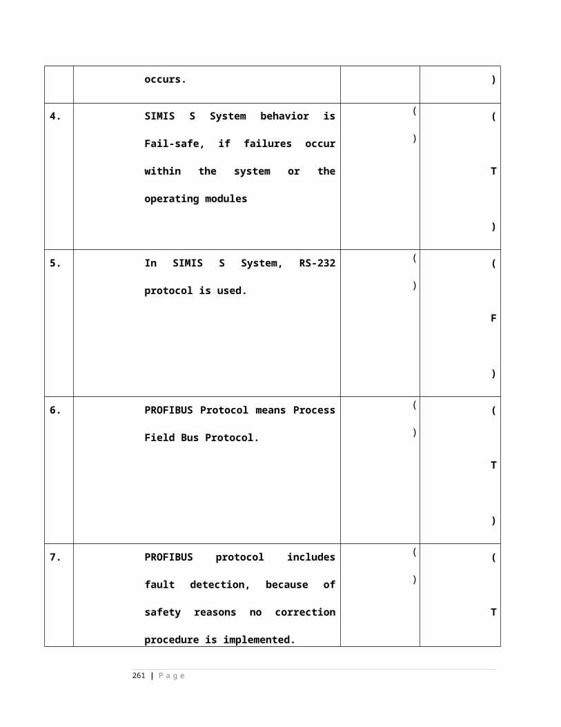
4 In SSDAC of CEL make, card no 7 is _________ A) Modem Card. B) Event Logger Card. C) Micro controller Logic Board D) Relay Driver Card.
( )
( D )
5 In SSDAC of CEL make, card no 8 is ________A) Modem Card. B) Event Logger Card. C) DC-DC Converter Card D) Relay Driver Card.
( )
( C )
6 In SSDAC of CEL make, card no 1&2 are _________ A) Modem Card.
B) Signal Conditioning Cards. C) Micro controller Logic BoardsD) Relay Driver Card.
( )
( B )
7 In SSDAC of CEL make, card no 3&4 are _________ A) Modem Card.
B) Signal Conditioning Cards. C) Micro controller Logic BoardsD) Relay Driver Card.
( )
( C )
8 In SSDAC of CEL make, _______ no. of conductors required for connecting two SSDAC units. A) 2 B) 4
C) 8 D) 10
( )
( A )
9 Baud rate of modem card in SSDAC of CEL is -------------------------- A) 56KBPS B) 3000BPS C) 300 BPS
( )
( C )
261 | P a g e
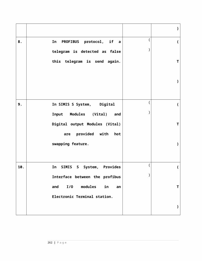
D) 9600BPS10 In SSDAC of CEL
make, the function of the Micro-controller Logic Board card is A) Wheel detection B) Train direction is checking and Wheel counting. C) Receives the remote wheel count and computes the status of the section for clear or occupied. D) all of these
( )
( D )
11 In SSDAC of CEL make, Input voltage of the DC-DC converter Card is
A) 12V DC B) 110V ACC) 24V DC D) 110V DC
( )
( C )
12 In SSDAC of CEL make, output voltages of the DC-DC converter Card is A) 5V DC & 12V DC B) 5V DC & 24V DC C) Both A & B D) None of these
( )
( C )
CHAPTER - 4
SSDAC- ELDYNE
1 Amplitude modulation technique is used in digital axle counters to avoid the trolley suppression track circuit.
True/False
( )
( F)
2 SSDAC- ELDYNE (AzLS) is containing 2 out of 2 micro-controllers to count the axles, establish the track occupancy of a track section.
( )
( T )
262 | P a g e
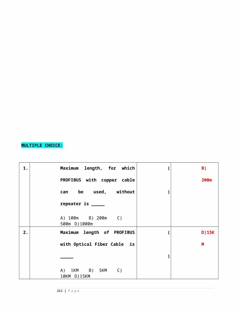
True/False3 The AzLS, consisting
double rail contact Sk30H and an electronic unit. True/False
( )
( T )
4 In AzLS, Analog card of Electronic Unit generates Tx signal, Amplifies Rx signal, does phase sensitive rectification and also generates wheel pulse of MESSAB and RADIMP.True/False
( )
( T )
5 In AzLS, Digital card of Electronic Unit Counts wheel pulse, Determines RCD, Supervises Rail Contact, Codes telegrams.
True/False
( )
( T )
6 AzLS can be configured as a single section axle counter with one Rail Contact (RC) and Electronic Control Unit (EAK) combination at both ends of the section and with a two-wire fault tolerant link (FTL) between the two. True/False
( )
( T )
7 In AzLS, additional Digital PCB or evaluator card is not required to be used at the common detection point (EAK).
True/False
( )
( F )
8 AzLS could be configured in a double section application including point zone application.
( )
( T )
263 | P a g e
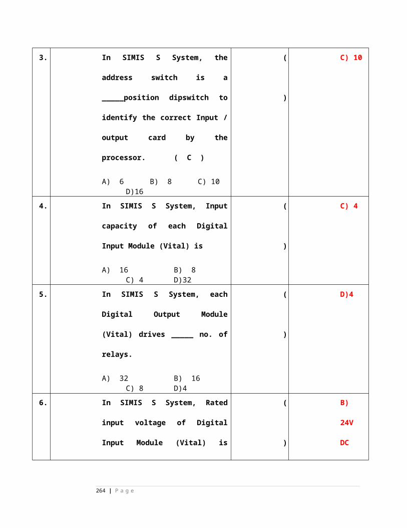
True/False
MULTIPLE CHOICE:
1 Baud rate in SSDAC of ELDYNE (AzLS) is ---------- A) 56KBPS B) 3000BPS C) 300 BPS D) 9600BPS
( )
( C )
2 In AzLS, EAK consists of ____________
A) Back plane B) Evaluator board C) Analog board D) all of these
( )
( D )
CHAPTER- 5MSDACState true or False
1 axle detectors do not detect push trolley with 4 / 6 / 8 spokes.
True/False
( )
( T )
2 In CEL MSDAC, Each field unit is connected to Central Evaluator on half Quad cable in Star Configuration.True/False
( )
( T )
MULTIPLE CHOICE:
1 Multi-section Digital Axle Counter system consists of ______________
( )
( D )
264 | P a g e
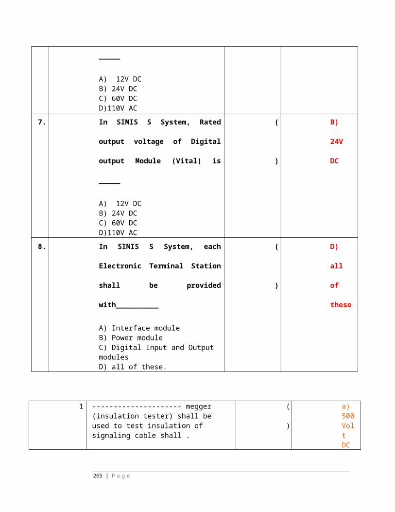
A) Detection Point
B) Central Evaluator Unit and Reset UnitC) Relay Unit and Event logger and diagnostic terminalD) All of these
2 In MSDAC, Central Evaluator unit drives _______ Vital Relay in order to give Free and occupied indication of an axle counter track section. A) 24VDC, 1000 ohms Plug-in type
B) 12VDC, 1000 ohms Shelf typeC) 110VAC, 1000 ohms Plug-in typeD) None of these.
( )
( A )
3 In CEL MSDAC, each Digital Axle counter field unit _____________A) is configured as one Detection point. B) Detects wheels and store counts based on 2 out of 2 logic.C)Transmits count and health information to Central Evaluator.D) All of these
( )
( D )
CHAPTER 6 & 7 MAY BE SHIFTED to ANNEXURES.
DATALOGGER
MULTIPLE CHIOCES
SL.No. Question ( ) Answ
265 | P a g e
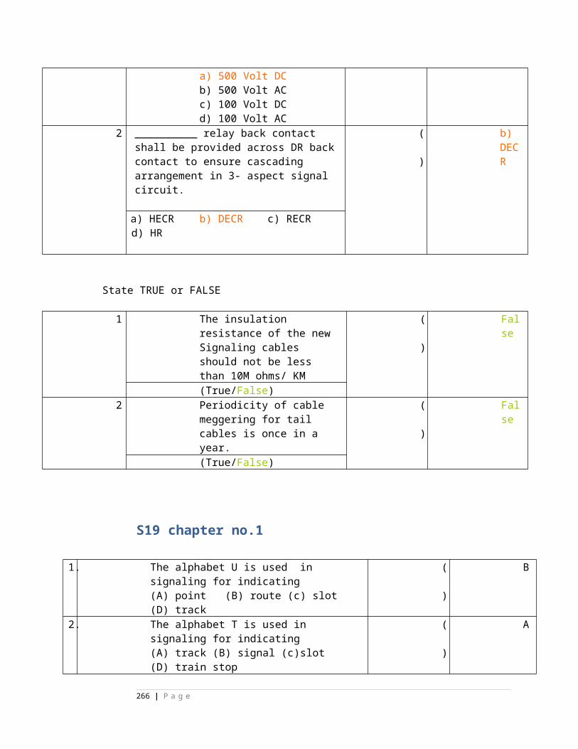
er
1 In EFFTRONICS Datalogger, capacity of each Digital input card is ____
inputs.
A) 16 B) 32 C) 64 D) 512
( C
)
2 In EFFTRONICS Datalogger, capacity of each Analog input card is
_________ no. of analog channels.
A) 16 B) 8 C) 4 D) 2
( B
)
3 In EFFTRONICS Datalogger, all Digital inputs are scanned at the rate of
______ m. sec.
A) 16 B) 32 C) 64 D) 512
( A
)
4 In EFFTRONICS Dataloggers, all the Analog inputs are scanned at the
rate of ------------.
A) 16 m.sec B) less than 1 sec.
C) 32 m.sec D) 1 minute
( B
)
5 In EFFTRONICS Dataloggers, DSU is required only when the system is
required to be connected with more than ______ no. of relays.
A) 64 B) 128 C) 512 D) 1024
( C
)
6 Digital input capacity of Datalogger system is ____________.
A) 512B) 1024 C) 64 D) 4096
( D
)
7 Analog input capacity of Datalogger system is ____________.
A) 24 B) 96 C) 64 D) 32
( B
266 | P a g e
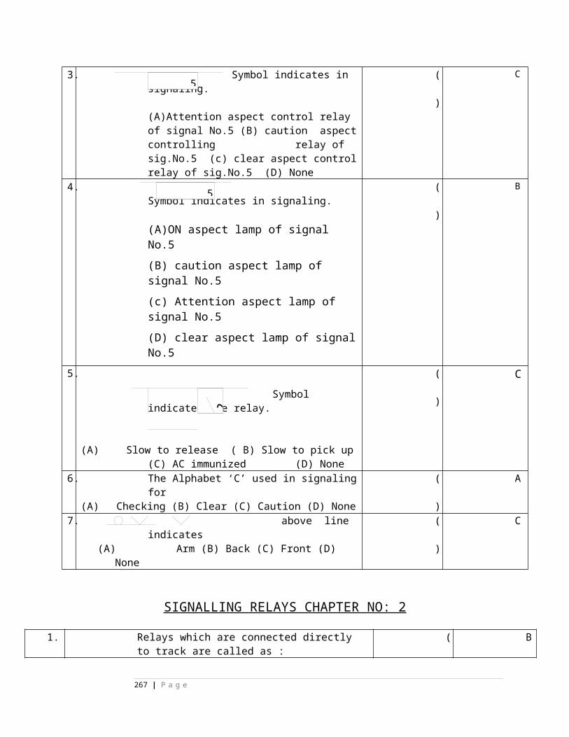
)
8 Minimum no. of Analog channels is required to be provided with
datalogger system is ___________
A) 16 B) 24 C) 32 D) 96
( C
)
9 Minimum no. of Digital inputs are required to be provided with
datalogger system is ___________
A) 64 B) 256 C) 512 D) 4096
( C
)
10In EFFTRONICS Datalogger, each DSU is provided with maximum of
_________ no. of digital input cards.
A) 16 B) 8 C) 4 D) 2
( B
)
No.Question Answer
267 | P a g e
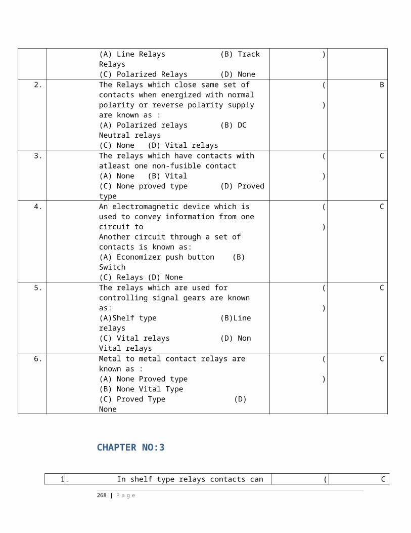
1 Data logger records data of analog signals & digital signals.True/False
( ) True
2 Data loggers cannot be connected on network True/False
( )False
3 For making reports, printing of data is possible locally as well as at centralized placeTrue/False
( )True
4 Relay data is stored with respective to date and time in the datalogger system, only when there is a change in status of the relay.True/False
( )True
5 In networking of Dataloggers modems are required to be provided.True/False
( )True
6 In networking of Dataloggers, “ORG” Modem of one station can be connected to “ORG” Modem of the adjacent station.True/False
( )False
7 In networking of Dataloggers, FEP is required at Centralised Place, where you want to monitor the data of all the stations.True/False
( )True
8 In networking of Efftronics Dataloggers, Central Monitoring Unit is provided with Nmdl, Fault entry, Reports and Track OFF software.True/False
( )True
9 Datalogger stores 10Lakhs events.True/False
( )True
10 In EFFTRONICS Datalogger, each ASU is provided with maximum of 4 no. of analog input cards.True/False
( )False
11 Dataloggers are very much useful for accident analysisTrue/False
( )True
12 With the help of datalogger, Train Signal passing at Danger events may not be analysed.True/False
( )False
13 With the help of datalogger, Speed of a Train can be analysedTrue/False
( )True
14 With the help of datalogger, Un-Signal Movement can be analysed.True/False
( )True
15 With the help of datalogger, power supply fluctuations can be analysed
True/False
( )True
16 In AWS, opto coupler card senses the aspects information of signal and connects
the same to track magnet.
True/False
( )True
268 | P a g e
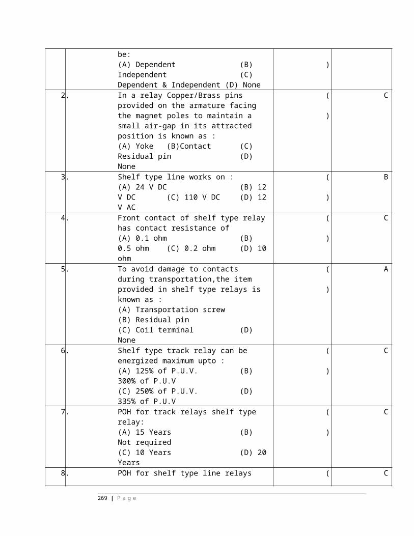
17 In AWS, Engine Magnet transmits 50Hz and 100Hz frequencies to
Track Magnet.
True/False
( )True
18 In AWS, Track magnet works on 24V DC.
True/False
( )False
19 AWS applies brakes whenever Driver passed signal at Danger.True/False
( )True
20 AWS continuously monitors train speed and direction of movement.
True/False
( )True
21 ACD prevents train collision in the mid section and station sections.
True/False
( )True
22 ACD is having Door –Drishti of 3 Kms in all Weather conditions.
True/False
( )True
23 ACDs are provided with Radio Modems for Inter-communication
between them.
True/False
( )True
24 In ACD, UHF radio modem communication is used for tracking the train.
True/False
( )False
25 ACD detects Train Parting.
True/False
( )True
26 ACD alerts driver on 'Station Approach'.
True/False
( )True
27 Alerting the driver and regulating the train speed to 25KMPH, when it detects (through the Loco ACD of other train) that it has stopped in mid-section.True/False
( )True
28 TPWS facilitates to run the train at maximum permitted speed by providing the ( )True
269 | P a g e
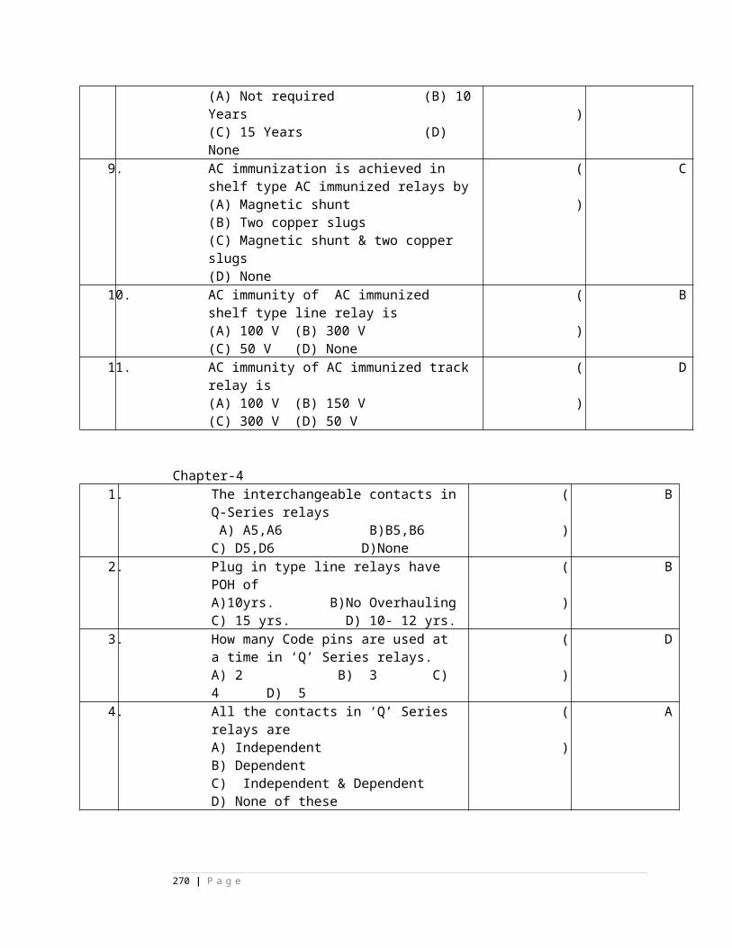
indication to the driver 500 meters in advance of signal.
True/False29 TPWS facilitates to run the train at maximum permitted speed by providing the
indication to the driver 500 meters in advance of signal.
True/False
( ) True
30 TPWS facilitates normal operation of train in dense foggy condition where visibility is near zero.True/False
( )True
QUESTION BANK IN POWER PLANT (T-10A):
OBJECTIVE: BATTERIES:Fill up the blanks with suitable words:1) I.S. Specification number of battery graded Con.Sulphuric acid __________ (IS266-
1977)2) I.S. Specification number of Battery graded Distilled water is__________(IS1069)3) I.S. Specification number of acid resistant paint is___________.(4) I.S. Specification number of Plante positive Lead acid cells __________.5) I.S. Specification number of pasted plates Lead Acid cells __________.6) I.S. Specification number of tubular positive Lead Acid cells __________.7) I.S. Specification number of Dry Leclanche cell is ____________.8) I.R.S. Specification number of Auto/Manual battery charger ___________.9) I.S. Specification number of Ni- Cd rechargeable pocket plated batteries
is______________.10) I.R.S. Specification of Low maintaince lead acid batteries is__________.11) I.R.S. Specification number of SMF lead acid batteries is_____________.12) Voltage of a fully charged Lead Acid cell is______________.13) Lead Acid cell can be discharged up to voltage of ____________.14) Separators prevents ____________ between _______ & __________ plates in Lead
Acid cell.15) The active materials in Lead acid cell are ___________, ________ &_____________.16) A 400Ahcapacity Lead Acid cell can be charged with a maximum current of
___________.17) Capacity of any Lead Acid cell is given in___________ with ________ Hrs rating.18) Electrolyte used in Lead Acid cell is _______ _____________.19) Specific gravity of battery graded Con. Sulphuric Acid is ____________.20) Initial charging current rate can be taken as _______% of its capacity in case of L,A,
cells if manufacturer’s rating is not available.
270 | P a g e
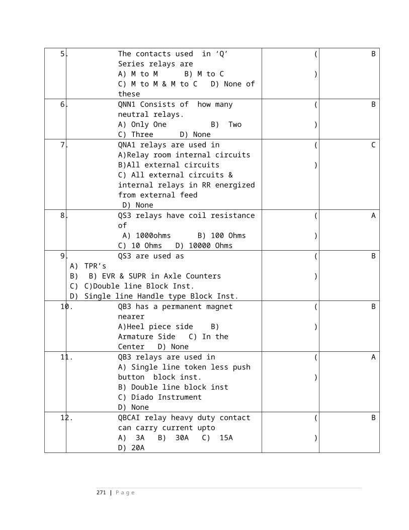
21) Maximum electrolyte temperature allowed during Initial charging of Lead Acid Cell is__________ºC.
22) Electrolyte for lead acid cell can be prepared by adding _________ to __________ in small quantities.
23) To avoid lead corrosion on battery connectors and terminals apply ______________ or _______________.
24) Per cell voltage in case of Float charging is_________.25) Per cell voltage in case Boost charging is___________.26) The rate of self discharge in case of Lead Acid cell can be taken as______ per AH.27) Specific gravity of electrolyte varies with temperature at the rate of ___________ per
1ºC.28) The measuring instrument used for measuring Specific gravity is _____________.29) Sulphation can be identified by ____________ & ___________.30) Sulphation in Lead Acid cell increases ___________________ in Lead Acid Cell.31) In VRLA cell/battery the compensation of distilled water is by _________________.32) In VRLAB the pressure inside is regulated by ___________.33) ____________ indicates the fully charged condition of Lead Acid cell.34) Internal resistance is maximum at _________ Specific gravity.35) If temperature increases the specific gravity _____________ in Lead Acid Cell.36) After discharge, both the plates becomes ________ in Lead Acid Cell,37) The level of electrolyte above the plates should be always_________.38) Buckling of plates in Lead Acid cell is due to _________________ of plates.39) During Initial charging, the charging can be stopped only after ____ % of AH input is fed.40) The insulating pieces between positive and negative plates of a cell are called as
_____________.41) The ratio of Acid to Distilled water to get 1200 Specific gravity electrolyte is______:
________.42) Voltage of a fully charged Nickle Cadmium cell is __________ .43) Electrolyte used in Ni-Cd cell is _____________.44) The active material on +ve plates in Ni-Cd cell is _________________.45) The active material on –ve plates in Ni-Cd cell is _________________.46) When Ni- Cd cell is discharged the Cadmium Hydroxide is reduced to
__________________.47) In Ni-Cd cell, the Lithium hydroxide is added to electrolyte to
________________________.48) In Ni-Cd cell the plate grids are made from _________ _______ ________
_______________.49) Specification number of sealed cylindrical Ni-Cd cell is ______________.50) Capacity range of pocket plated Ni-Cd cell is ________________.51) The material used for separators in Ni-Cd cell is __________________.52) In Automatic Battery charger the output controlling device is ______________.53) Recommended current rating of charger for an 80AH battery with maximum permissible
load of 12 Amps is ___________ Amps.54) Automatic battery charger under S-86/20000 specification cansupply constant output voltage for A.C. input variation from ________Vto ______ V.55) The rectifier circuit converts ___________ to ___________.56) In case of Ferro resonant type automatic regulator for sudden changes of input voltage
or Load variation the response time is < ____________.57) In case of Ferro resonant type automatic regulator short circuit protection is achieved
by__________________ winding.
271 | P a g e
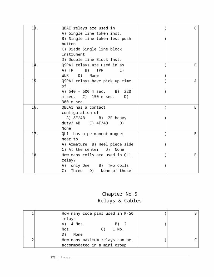
58) Voltage of a Solar cell is ____________ .
59) Charging current should be reduced when the battery starts _____________.60) Per cell voltage in case of Initial charging is_____________.61) Per cell voltage in case of Boost charging is____________62) Per cell voltage in case of Float charging is_____________.63) In case of Ni-Cd cell/Battery , charge input during first charge should be __________
capacity of C5 AH.64) ____________ are formed on the plate surphase , when Sulphated.65) Note down ___________ ____________ of each cell periodically.66) The material used for grids in MFB is __________________.67) Topping up with distilled water in case of HDP plante Lead Acid cells can be done once
in ________months.68) Terminal voltage of a fully discharged Ni-Cd cell is____________.69) When the Lead Acid cell is discharged completely, both the plates are converted into
____________ .70) The material used for grid structure in Lead Acid cell is______________.71) The insulation resistance of Mains transformer in battery charger should be more than
____________ M Ohms.72) In battery charger the current rating of Diodeds & SCR’s should be more than
____________ current flowing through them.73) The resistors power rating, used in battery charger should be __________.74) Voltage rating of capacitors used in chargers should be _______٪ above peak value.75) I.S. Specification number of HRC fuses is ______________.76) Additional protection for chargers rated above 50 Amps shall be provided with extra
_____________ & ___________.77) Ripple in D.C. output of battery charger should be less than_________٪78) Psophometric noise voltage in the output of a battery charger should be less than
__________ Mv.79) The charger works in ________________ condition, if battery draws current less than
5% of its set value.80) The charger switches to ____________ when the battery draws currewnt more than 8-
12% of the set current.81) Power factor of an Automatic battery charger must be above _______ lagging in all
modes.82) No load AC input current shall be __________ value in case of Automatic battery
charger.83) In Automatic battery charger the gate pulses for SCR’s is generated by ____________
circuit.
84) In case of Automatic battery charger permitted variation in the output voltage over the entire range of input AC supply variation is ___________.
85) The grid structure of Lead Acid cell is made from _________________ or ________________alloy.
86) Permissible raise in temperature above amient for Mains Transformer shall be __________.
87) ON/OFF switch in battery charger shall be of _____________ pole type.88) The range of voltage control potentio meter in a battery charger shall be___________ to
__________ V.89) In chargers above 50Amps rating series fuses to be provided for ______________ &
____________ elements.
272 | P a g e
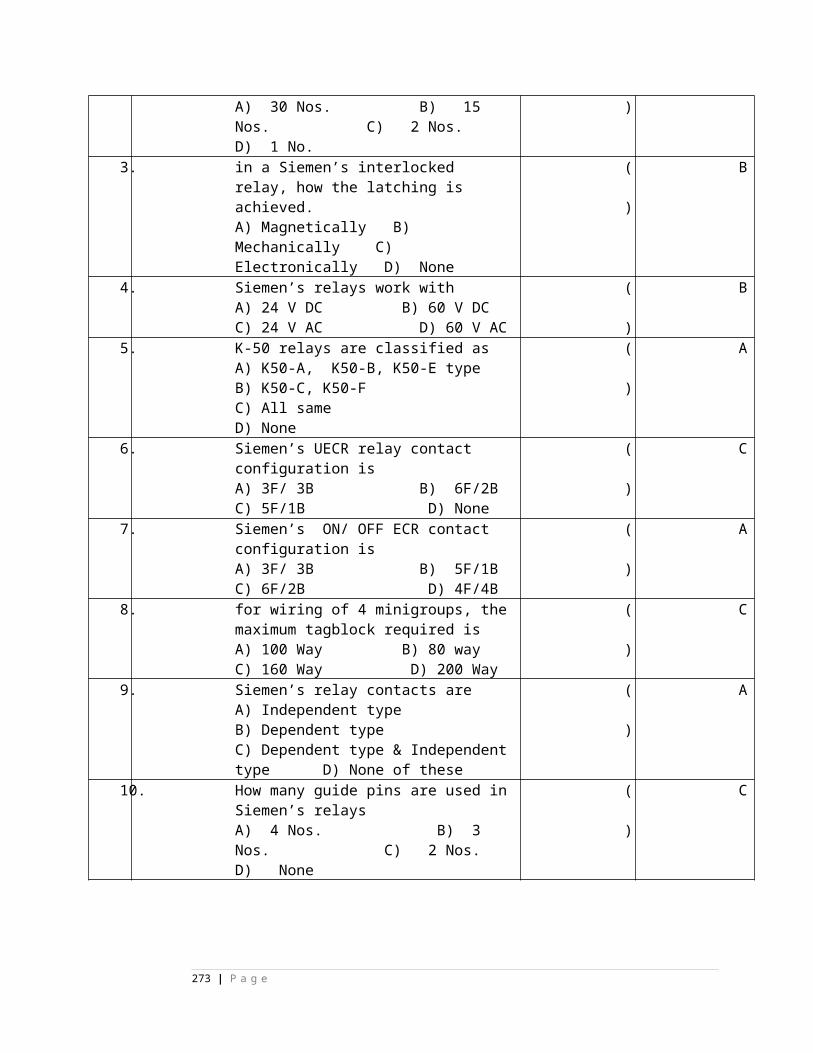
90) Specific gravity of electrolyte ____________ when temp decreases.91) Specific gravity correction factor per 1ºC is___________.92) Equavalising charging is necessary to a battery connected in ___________ charging .100) Use of ballast resistance in a battery charger is_______________.
101) Check _________, __________, ________ for every 8Hoursduring initial charging102) Voltage of a Secondary cell depends on ______________ & ______________103) A 300 AH 10H battery can supply 20 Amps current for ___________ number of hours.104) IS Specification of a plante positive type cells is ________________ (IS-1652)105) IS Specification of Tubular positive type cells is _____________. (IS-1651)107) Specific gravity correction factor per 1ºC is _____________.108) Negative plates are one more than the positive plates to provide ______________________.109) Vent holes are provided in vent cap to for ____________ to ______________.110) The level of electrolyte in Lead Acid Cell is indicated by ____________________.111) The level of electrolyte inside the cell is always be _______ '' above the plates.112) The current inside the cell is carried by _____________.113) The separators used in VRLAB are made from _______________.114) The grid in VRLAB are made from _______________ alloy.115) The normal battery operating temperature is ________ºC.116) SMF cells need much addition of distilled water due to _________________ principle.
INVERTER:1) The electronic device which converts AC to DC is called as _______________.2) Inverter converts ____________ to ___________.3) Efficiency range of an inverter should be within _________% to __________%,4) Output frequency of inverter should be _____________5) In case of solid state inverter no load current shall not exceed _______% of full load current.6) Inverters of 500VA and above shall be provided with __________& __________ indications.7) The PWM IC number used in 500 Watts inverter is ______________.8) SG2535A is an _______________________________ I.C.9) EMI/RFI filter is connected on the ______________ side of the inverter.10) The inverter automatically shuts off when battery voltage goes below ___________ volts.11) The inverter will be in OFF condition when mains A.C. supply is ___________.12) The Oscillator frequency inside the SG3525A I.C. is ________ Hz.13) The power amplifier stage in inverter uses _______________ as power amplifier device.14) MCCB means____________ _______ __________ ___________.15) The changeover time to inverter during Mains power failure is in ________16) Shut- off input to IC SG3525A is given to pin No_______________.17) The insulation resistance of the inverter shall not be less than_________M Ohms under 40ºC.
273 | P a g e
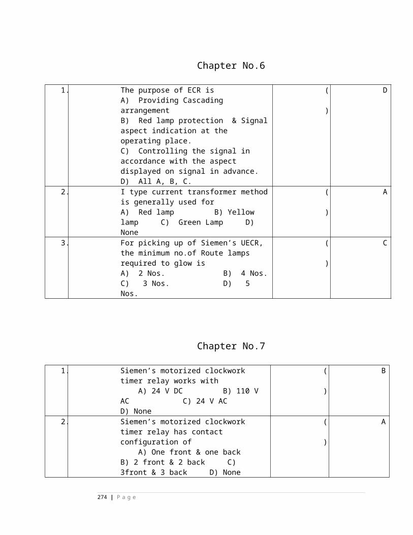
Solar cells:1) Solar cells converts __________ energy to _________-- energy.2) Solar panel is a combination of _________ connected in ___________ & __________
fashion.
3) The solar cell is made from __________ & ______________ materials.4) Generation of electricity from Sun light is called as________________5) A typical Solar cell is nothing but __________________6) Conversion efficiency of a Silicon solar cell is _________________.7) Falling of dust, dirt and snow, decreases the Solar arrays ___________
8) A solar panel is installed inclined at an angle equal to the _____________ of the plane. 9) Surface of solar cell is coated with ________________ coating to increase _____________. 10) Open circuit voltage of a solar cell is _______ V.
Say TRUE or FALSE:1) Hexagonal shape of a solar cell provides more utilization area ( )2) Solar cell converts “Electrical energy” into “Solar energy” ( )3) Solar panel is a combination of solar cells ( )4) Voltage of each solar cell is 1.2 V( )5) Solar cells are made from semiconductor materials ( )6) The semiconductor material used for solar cell is Aluminium ( )7) Solar cell produces pollution ( )8) Efficiency of a Solar cell is very high ( )9) Solar system is having longer life ( )10) Conventional Lead Acid Cells are suitable for Solar panel ( )
Uninterrupted power supply (UPS):
1) In Off-Line UPS the inverter is ON only when the mains supply __________. 2) Change over time in ON-line UPS is _____________ mS
4) ____________ of batteries are preferred in UPS.5) Regulation of output voltage is done by using __________ principle in UPS6) Normal PF rating of UPS is ________7) In ON-Line UPS the battery will be always in ___________ condition.8) __________ or __________ device are used in Power Amplifier stage of UPS.
Say TRUE or FALSE:1) In Off-Line UPS the inverter is always in ‘ON’ condition ( )2) In ON-Line UPS there is no change over time ( )3) In put to UPS is A.C ( )4) In OFF-Line UPS the relay will be OFF condition when AC input is present ( )5) UPS backup time can be increase by increasing the capacity of the battery ( )6) Only a single transformer is sufficient in ON-Line UPS ( )
274 | P a g e
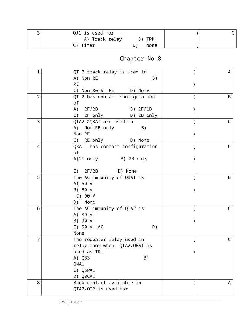
7) In OFF-Line UPS the battery will be charge only when the inverter is ON( )
8) For UPS with rating higher than 2KVA IGBT device is used in power amplifier
stage( )
Choose correct answer:
1) The backup time in UPS depends on,
( ) A) Load B) Voltage C) Batter capacity D) all the three
2) The type of UPS used in Medical side is,( ) A) ON-Line B) OFF-Line C) Line interactive D) Non of the above
3) Malfunctioning of UPS is avoided by incorporating,( ) A) Fuse B) EMI/RFI filter C) Only filter D) controlling device4) Input to an UPS is,( ) A) Battery B) AC mains voltage C) rectifier output D) non of above
SMPS:
1) The switching & controlling element in SMPS is ___________________.2) The output voltage of SMPS is regulated by,
( ) A) converter transformer B) pulse width of controlling pulses
C) input rectifier D) filter circuit
3) SMPS of 100 Amps rating requires 3 SMR modules of each rating ,( ) A) 50Amps B) 25 Amps C) 100 Amps d) any value
4) The switching device used in SMPS is ,( ) A) transistor B) IGBT C) MOSFET D) Diode 5) The switching device in SMPS operates at,( ) A) above 100KHz B) VF range C) 10-100 KHz D) 10-100MHz6) The converter transformer in SMPS operates at low frequency ( )
12) The switching device in SMPS will be in always On condition ( )
13) SMPS is a modular type power supply ( )
Say TRUE or FALSE :- 1) The grids and separators will be effected if the specific gravity of electrolyte isbelow 1.240 ( )2) The internal resistance is minimum at specific gravity 1.240 in Lead Acid cell( )
275 | P a g e
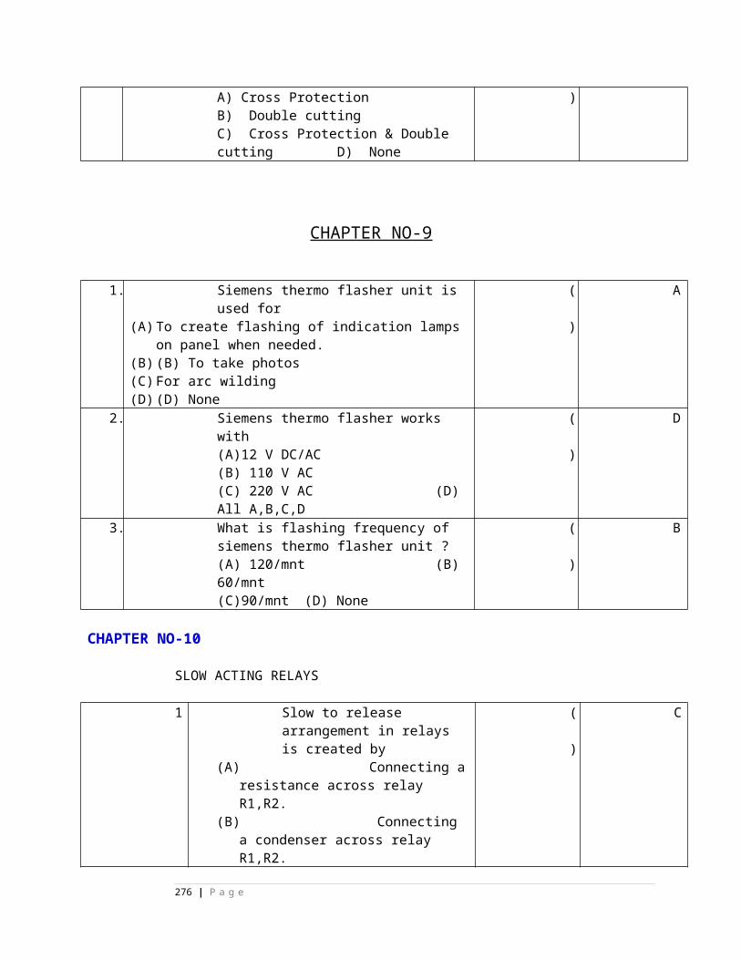
3) Capacity of a Lead Acid cell is directly proportional to its length of service ( )4) The Initial charging current is less than normal charging current ( )5) Electrolyte can be prepared by adding distilled water to Sulphuric Acid( )6) During Initial charging add only distilled water ( )7) The battery which is kept continuously under “Float charging” should be given “ Equavalising charge” to compensate low or uneven Sp. Gravities of cells ( )8) Buckling is one of the causes for internal short circuit ( )9) The internally short circuited cell gasses freely ( )10) Buckling of cell plates takes place due to excessive charging or discharging ( )11) Shedding means falling of active material from the plates ( )12) Do not allow the batteries to get fully discharged ( )13) Boost charging charges the battery quickly ( )14) The internally short leads to reverse polarity of the cell ( )15) Formation of lead corrosion at cell terminals causes high resistance ( )16) Rate of Trickle charging is 100 mA/AH capacity.17) Distilled water to be added in MFB ( )18) Initial charging is a constant potential type of charging ( )19) Gas recombination principle is used in maintaince free sealed L.A. battery( )20) Constant potential method is used to charge VRLA battery ( )21) Voltage of a fully charged Ni-Cd cell is 2.1 V( )22) Distilled water to be added during initial charging to maintain the level ( )23) Initial charging can be stopped before 50% of charging is completed ( )24) Trickle charging is given to a fully discharged battery ( )25) Boost charging is a constant potential type of charging ( )26) The nominal cell voltage of a MFB lead acid battery is 2V ( )27) Calcium alloy is having lower self discharge and increased conductivity ( )28) Maximum electrolyte temperature allowed during charging is 100ºC ( )29)The active material on the positive plates in Lead Acid cell isSpongy Lead ( )30) Con. Sulphuric Acid is used as electrolyte in Lead Acid Cell ( ) 31) Secondary cell voltage depends on the number of plates ( F )32) Ampere-Hour efficiency can be increaswd by controlling thje charging current ( T )33) Efficiency of a secondary battery is defind as the ratio of input devided by output ( F )
DG Set:Fill up the blanks with suitable words:
1) The D.G. Set converts _____________energy into ______________ energy.
2) In Diesel engine the ___________ is compressed in the cylinder.
3) During ______________ stroke the power is transmitted to the crank shaft.
4) The liquid fuel is sprayed into the cylinder by ____________.
5) The out-put voltage of generator is controlled by controlling the
______________ of the shaft.
276 | P a g e
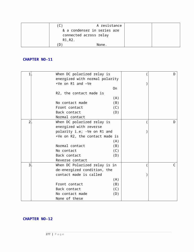
6) The speed of the Diesel engine is controlled by providing ________________
on the engine shaft.
7) The fuel used in Diesel engine is __________ oil.
II. CHOOSE CORRECT ANSWER:
1) The paper element of fuel filter is to be changed for every,
( ) A)250 Hrs B) 500 Hrs C) 800 Hrs D) 50 Hrs
2) Speed of the prime mover at full load is,
( ) A) 1200 RPM B) 1560 RPM C) 1570 RPM D) 1500 RPM
3) Engine starts and stops due to,
( ) A) Fuel tank filled completely B) air in fuel lines C) piston defective
D) non of the above
4) Compression ratio in Diesel engine is,
( ) A) 16:1 B) 1:16 C) 10:1 D) 5:1
5) Both the valves are closed during.
( ) A) suction stroke B) compression stroke C) exhaust stroke D) non of
the above
7) The valves in DG set are lifted by,
( ) A) Cams on cam shaft B) piston C) crank shaft D) non of the above
8) Engine starts but stops after some time due to,
( ) A) Air in fuel line B) Oil tank is full C) piston faulty D) non of the three
9) The fuel in diesel engine is ignited by,( ) A) spark plug B) Compression C) piston D) Non of the three
10) Lubricating oil in Diesel engine is located at,( ) A) Tank B) piston C) Sump D) non of the three
11) The fuel filter in Diesel engine is to be replace after,( ) A) 500 Hrs B) 800 Hrs C) 1000 Hrs D) 500 Hrs
III. Say TRUE or FALSE:-
1) Spark ignition system is required in diesel engine ( )
277 | P a g e
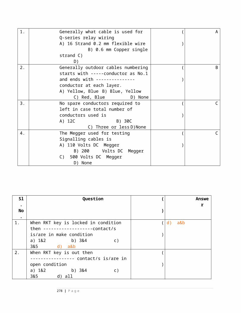
2)Fuel tank in diesel engine should be cleaned for every 250 hours
of working ( )
3) Excessive fuel consumption is due to incorrect value of fuel timing ( )
4) The exhaust valve opens during power stroke ( )
5) Governor throttle regulates the amount of fuel supplied to the
engine ( )
18) The diesel engine is to be overhauled for every 500 Hours ( )
19) The power is transmitted to alternator by camshaft in diesel engine ( )
20) The valves are opened by livers in diesel engine ( )
IV) MATCH THE FOLLOWING:
( ) 1. Injector A) low ESR filter capacitors
( ) 2. Piston B) stores mechanical energy
( ) 3. Radiator C) charge/discharge system
( ) 4. Fly wheel D) Cooling system
( ) 5. SMPS E) compress the air
( ) 6. Linear power supply F) spray liquid fuel
( ) 7. Micro wave station G) low efficiency
( ) 8. clean the air filter H) after 250 Hrs
( ) 9. change the air filter I) for every 50 hrs element
( ) 10. Clean the sump J) after 800 Hrs
CABLES
Fill in the blanks:1.RE cables VF quads are ---------- insulated. 2.PET quads are used for----------in RE main cable.
278 | P a g e
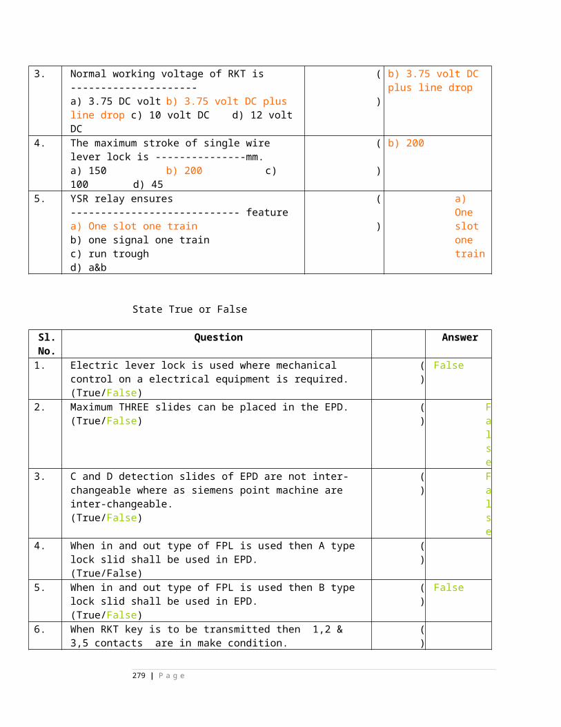
3.The characteristic impedance of PET quads is--------.4.Loading section length of RE main cable is--------.5.Screening factor of lead sheathed cable is--------.6.RDSO specification 6 quad jelly filled cable is --------.7.SWBD cables are used for--------- wiring.8. The inductance value of loading coil used in RE main cable is---------.9) Impedance of paper insulated pair of RE cable is ________________.10) Value of loading coil used in 6Quad cable is _____________11) The instrument used to measure the capacitance unbalance in cable is known as ____________. 12) At road crossings the cables should be drawn through ________________.13) The cable used for emergency purpose is called as _________________14) Before laying the cable should be tested for proper _____________ & _________________.
STATE TRUE OR FALSE:1) Conductor dia of re derivation cable is 0.9mm ( )2) RDSO specification for RE main cable IRSTC30/97 ( )3) Quad cables are not used in Non-RE area ( )4) 6 quad cable loading section length is 2 km ( ).5) 6 quad cable is paper insulated ( )6) Emergency control post is provided for every 1 km. ( )7) Loop resistance of 6 quad cable is 600 ohms ( )8) RE main cables are aluminum sheathed ( )
CHOOSE CORRECT ANSWER:1) Loop resistance of 1 Km RE main cable is ,( ) (A) 560 Ohms (B) 56 Ohms (C) 0.56 Ohms (D) 470 Ohm2) The purpose of Armour in RE cable is, ( ) (A) mechanical protection (B) to screen the induced voltages © protection from moisture (D) protection from soil3) Distance of Loading coil joint in a Loading section in RE section is,( ) (A) 915 mtrs (B) 1830 Mtrs (C) 457 Mtrs (D) 200 Mtrs
4) The purpose of Al screened wires in 6Q cable is, ( ) (A) mechanical protection (B) to screen the induced voltages © protection from rats (D) protection from soil5)The insulation test on RE cable is to be carried out for every,( ) (A) 3 Months (B) 1 Month (C) 6 Months (D) non of the above
6) Switch board cable is used for ,( ) (A) Indoor (B) Outdoor (C) both places (D) under ground
279 | P a g e
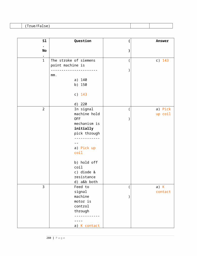
280 | P a g e
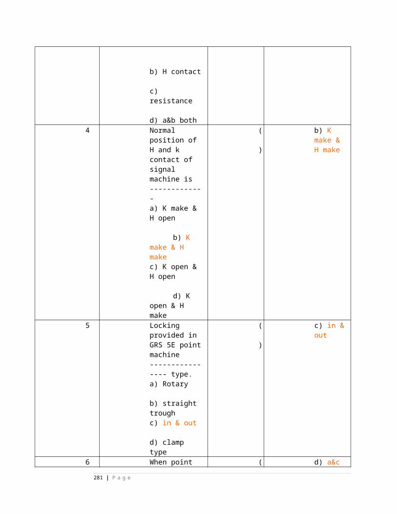
CHAPTER XXIX
BOOKS OF REFERENCE29.1 BOOKS OF REFERENCE : Books of reference should be supplied to Officers, Supervisors and Maintainers for their personal use, as well as for use in their offices. A statement showing the various books and their distribution is at Annexure A. For the officers, this list should be read in conjunction with Para 8.17 of Indian Railways Signal Engineering Manual, Part 1 (1988 edition)
29.2 RESPONSIBILITY : All officials to whom books of reference have been supplied shall be responsible for:
a. their safe custody and good order, b. pasting all addenda and corrigenda slips promptly and seeing that these are up to date to the last slip as notified from time to time, and c. returning all books issued to them for personal use prior to retirement or resignation or transfer from the railway service.
29.3 INSPECTION : Each Senior Divisional Signal & TelecommunicationEngineer/ Divisional Signal & Telecommunication Engineer shall make periodical checks tosee that Inspectors maintain their books of reference up to date and in good order. EachInspector shall, likewise, see that the staff under him maintain their books of reference up-to-date and in good order.
29.4 ACCOUNTAL : All books of reference should be accounted for in the same wayas tools and plant items.29.5 REPORTS OF TELECOMMUNICATION STANDARD COMMITTEE, TECHNICAL PAPERS AND JOURNALS : Each Senior Divisional Signal & Telecommunication Engineer / Divisional signal & Telecommunication Engineer should arrange to have the under-mentioned technical literature in his office library :
281 | P a g e
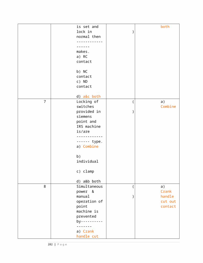
a. Reports of Telecommunication Standards Committee Meetings.
b. Proceedings & Technical papers issued by Institution of Telecom Engineers, India, Institute of Electronics & Telecommunication Engineers, Institution of Railway Signal & Telecommunication Engineers.
c. All IRS Specifications pertaining to Telecommunication, relevant BSS, ISS & DOT(TEC) specifications.
d. Quarterly Technical Bulletin and other technical papers on telecommunication matters published by the Railway Board.
e. Technical books and journals of interest on telecommunications.
f. Copies of technical instructions and reports issued by RDSO on different items of work relating to underground telecom cable installations, such as Technical Instructions on `balancing of VF cable', `jointing of cables', `installation of loading
282 | P a g e
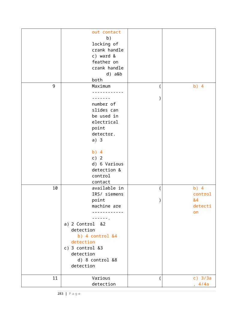
coils', `installation of VF repeater station equipment', `cable laying practice for optical fibre cables', `testing of digital microwave equipments' etc.,
29.6 RESPONSIBILITY OF DSTE : The Senior Divisional Signal & TelecommunicationEngineer / Divisional Signal & Telecommunication Engineer should encourage hissupervisors and other staff to study these reports, proceedings, papers and journals, so as toenhance their knowledge and to keep themselves informed about the up-to-datedevelopments, methods and techniques in telecommunications. He should arrange to circulateparticulars of all new publications that are received from time to time for the information ofsupervisors once every three months.
ANNEXURE -A Para 29.1
STATEMENT SHWONG THE VARIOUS BOOKS OF REFERENCE AND THEIR DISTRIBUTION AMONG STAFF
Item Publications Scale forNo. Office of Personal possession of Sr.DSTE/DSTE
Sr.DSTE/DSTE SSE/SE(Tele)
Maintainer SE(Tele) ASTE
ASTE CSTE
283 | P a g e
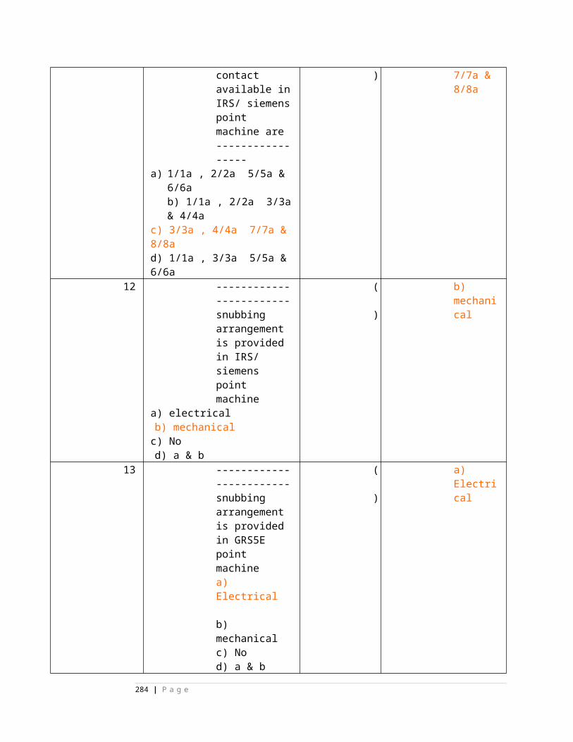
CSTE CCE
1 2 3 4 5 6 7 8 9 1 11 12 01. Telecommunication Engineering 1 1 1 1 1 1 1 1 1 1 Manual2. General and Subsidiary Rules 1 1 1 1 1 1 1 1 1 13. Stores Manual 1 - - 1 - - - - - -4. Pass Manual 1 1 - 1 - - - - - -5. Safety First Manual 1 1 - 1 1 1 1 1 1 -6. Schedule of dimensions 1 1 1 1 1 1 1 1 1 17. Telegraph Code 1 - 1 1 1 1 1 1 -8. Payment of wages act with 1 1 - 1 - - - - - - notifications as issued.9. The hours of employment 1 1 - 1 - - - - - - regulations with notifications as issued.10. Working Time table & Appendix 1 1 1 1 1 1 1 1 1 1 thereto11. Catalogue of Stores 1 1 1 1 - - - - - -12. Accident Manual 1 1 - 1 - - - -13. IRS Drawings(Telecom) 1 1 1 1 - - - - - -
284 | P a g e
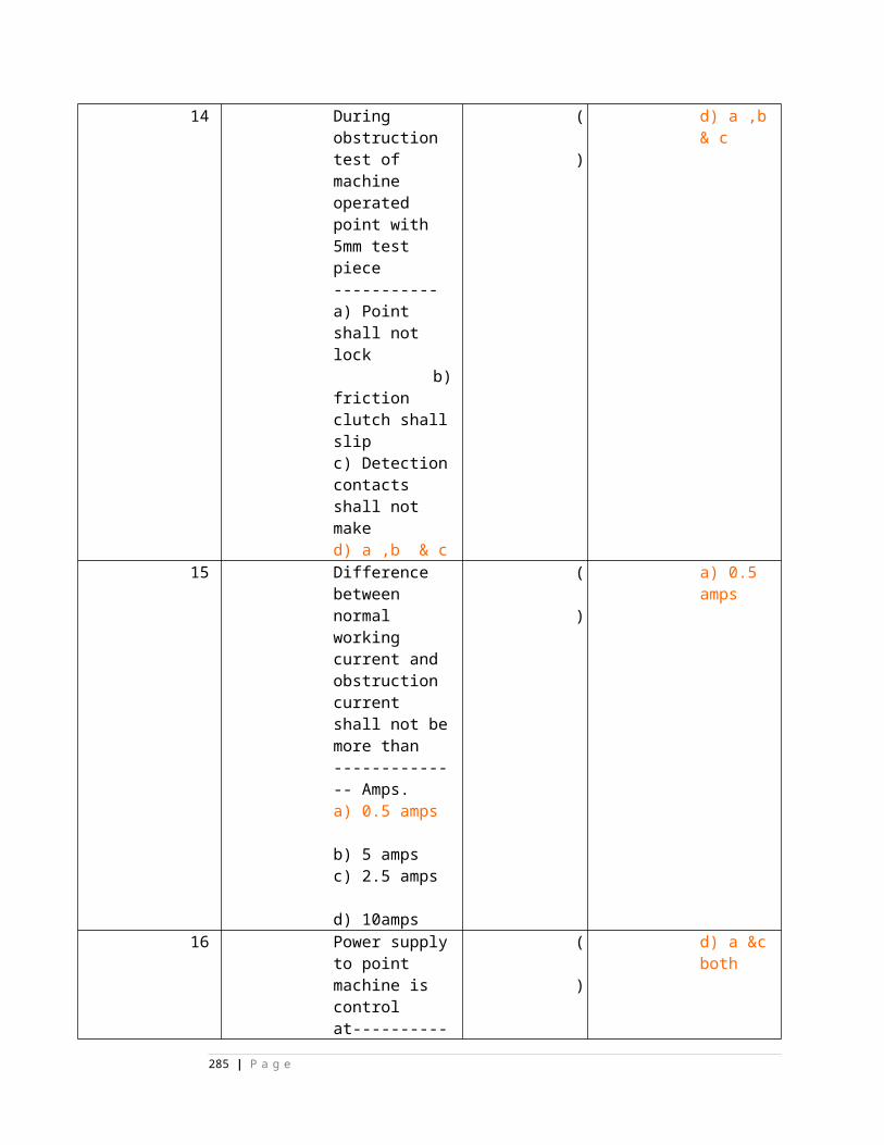
14. IRS specifications (of telecom items) 1 1 1 - - - - - - -15. Railway Standard Drawings 1 1 1 1 - - - - - -16. Indian Telegraph Act 1 1 - 1 - - - - - -17. Indian Government Railway Code 1 - - - - - - - - - for Engineering Department18. CCIR Documents of the plenary 1 - - - - - - - - - assembly19. CCITT documents of the plenary 1 - - - - - - - - - assembly20. Indian Electricity Act 1 - - - - - - - - -21. Electric Supply Rules 1 - - - - - - - - -
********
285 | P a g e
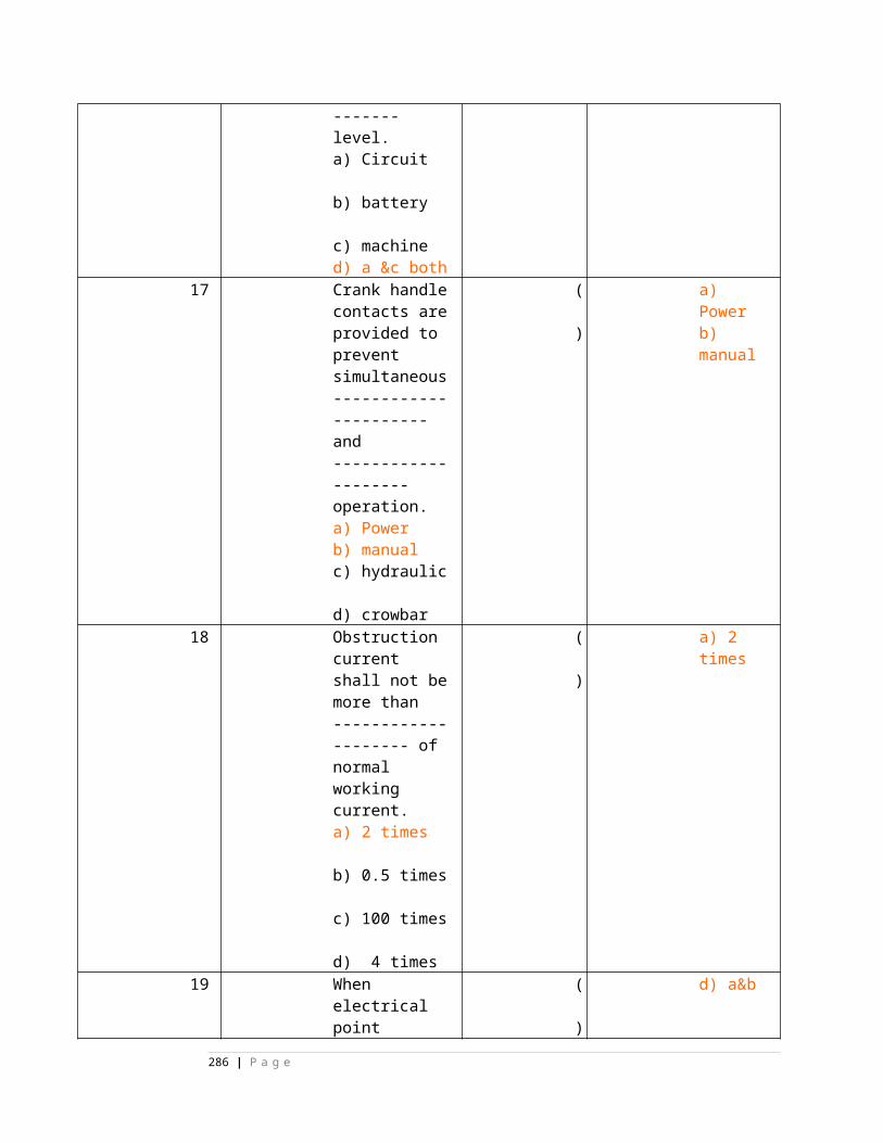
SYLLABUS for LDCE in S&T Dept.
PROFESSIONAL SUBJECT PART-I.
Maximum Marks 100 Time 3 Hours
NOTE: Total six questions to be answered Three in Part-`A' and Three in Part-`B' Four questions to be set in each part and threeout of four to be answered. `A'
General and Subsidiary Rules as applied to Railway operations,signalling and works connected with signalling and P.Way; Special reference asapplied to automatic signalling and APB(Auto Perm. Block) working; Rules for openingof a Railway with special reference to standards of interlocking at wayside stations,provision of signals at level crossing gates and outlying sidings; rules for working ofoutlying sidings with & without token control on single line; catch and slip sidings.Signal Engineering Manual with special reference to various requirements of blockworking, provision of signalling and interlocking; inspections to be carried out byofficers and subordinates etc. Telecommunication Engineering Manual with referenceto various types of line wire circuits and wireless circuits. Departmentally ownedTelecommunication alignments; various parameters valid for Copper, ACSR and G.I.wires and their limitations; improvement to communication circuits by patching withother carrier circuits, procedures for indenting of stores for revenue and works, impreststores, Stock sheets and other matters connected with goods store keeping practices;Block Working Manual, with regard to requirements of token and token lessinstruments on single line and double line instruments. Schedule of dimensions andoperating manual with special reference to infringements. Operations as affecting orguided by better Signalling and Telecommunication arrangements.
`B'
Fundamental Engineering and applied technology; simple machinery likeinclined plane, pulley blocks, travelling trollies, machines which aid in reduction of timeand labour in installation of various signalling gears; Principle of magnetism andelectricity as affecting the operation of signalling equipments like Relays both ACand DC, Point Machines, Signal Reversers, Signal Machines etc. Fundamentalelectronics with special reference to power supply and stabilisation of power supplyequipments. Simple digital circuits as required for digital clocks, Axle Counters etc.Heat engines and standby Diesel Generators with manual starting, electric starter andautomatic starter. A.C. to D.C. converters, D.C. to A.C. invertors and D.C. to D.C.converters as power supply sources in Signalling and Telecommunication. Special
286 | P a g e
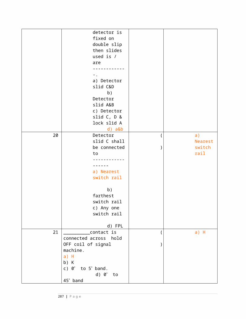
measures required for Telecommunication power supply to reduce noise. Powersupply distribution for signalling schemes with reference to voltage drop, size of cables
PROFESSIONAL SUBJECT PART-II.Maximum Marks 100 Time 3 Hours
NOTE:Total 6 questions to be answered. Four questions to be provided in each of the three parts `A', `B' & `C'. Three questions tobe answered from any one part and three from any of theother two parts. `A' (i) Mechanical Signalling with special reference to provision of rod and wire compensators, double wire operation of points; detectors and signals. Temperature compensation in both Orthodox and double wire Signalling. Various aspects of lever frames and methods of looking achieved. (ii) Basic principles of electrical interlocking with reference to track locking, back locking, approach locking, sectional route release and sequential locking. (iii) Track Circuits both DC and AC; Axle Counters as substitute for Track Circuits. (iv) Interlocking plans, locking tables and selection circuits. (v) Types of Point Machines with their special features including operating, control and detection circuits. Block Circuits for Token, Tokenless and Double Line Instruments, Direction Lever Working with Track Circuits and Axle Counters for single line sections, APB Signalling and intermediate block signalling. (vi) Automatic Signalling, Detailed Circuit operation for AC and DC Traction areas including cascading circuits. (vii) Simple Panel Interlocking, using metal to carbon Relays and metal to metal Relays. (viii) Route Relay Interlocking, Electronics Track Circuits, Automatic Warning System, Centralised Traffic Control.] (ix) Special features of Signalling in AC Traction Areas.
`B' Overhead line wire, underground cable system. Special armatures of circuits in25 KV traction areas. 2 wire to wire circuits. Conversion of 4 wire to 2 wire and 2 wireto 4 wire circuits. Control office and wayside station equipment of different types,emergency control communication equipments. Telephone Exchanges of PAX, PBX,MAX-II and MAX-I types. Trunk Exchanges of various types. Telegraphy-Horse,teleprinter circuits. Derivation of Telegraphic Channels through S+DX and VFT.Multiplexing equipments, derivation of channels by frequency translation using sub-groups, basic groups and super groups. HF-SSB Communication; multi-channelcommunication using VHF, UHF, Microwave Systems using Audio Relay methods,signal to noise ratio and fading.
`C'
287 | P a g e
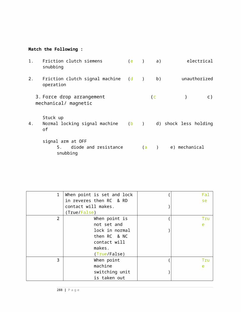
(i) Workshop practice Raw materials, processing, workshop machines and their utilisation. Quality control. Overhauling procedures and practices Inspection, stage and final and testing. (ii) Prime Movers. (iii) Manufacture of Axle Counters details components testing procedure commissioning and measurements. (iv) Repairs and testing of HF Transmitter, microwave trans-receiver, ultra sonic flaw detectors, automatic warning system. (v) Overhauling of Relays requirement procedure methodology etc.
NOTES ON ACCOUNTS FOR LDCE(S&T)
Compiled by: RPS YADAV, SSE/Tele/RE/AllahabadSYLLABUS
1. Parliamentary control over railway finance2. Public accountability3. Financial priority4. Financial planning & Budgeting5. Budgetary financial review6. Appropriation accounts7. Rules of allocation8. Classification of expenditure control over expenditure.9. Responsibility accounting10.Performance Budgetary11.Exchequer control12.Financial resulting of working13.Works program14.Financial justification of works15.Survey16.Preparation of estimates17.Capital budget18.Control over capital expenditure19.Productivity test20.Financial control over stores expenditure21.Purchase & stores keeping procedure22.Inventory control & ABC analysis23.Financial & cost control in railway workshops24.Rules & procedure relating to tenders & contracts for execution of works & procurement of stores25.Procedure for processing & finalizing the audit objections & draft Para26.Delegation of powers27.Losses frauds & embezzlements
288 | P a g e
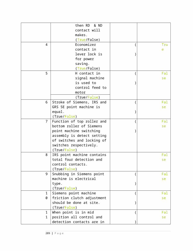
Notes of Establishment Rule for LDCE ( S&T )
Compiled by -- RPS Yadav, SSE/Tele/RE/AllahabadSyllabus 1. Organization of Personnel Dept in railways 2. Objective of Personnel dept 3. Functions & policies of personnel dept. 4. Role of personnel officers in HQ & Divn. 5. Classification of services Group A to D 6. Recruitment of artisan staff 7. Special reservations in railway services 8. Role of RRB in recruitment 9. Recruitment through other channels 10. Promotion policies & methods 11. Personnel supervision 12. Formal& informal democratic or participative leadership style 13. Advantage of participation 14. Joint council management 15. Negotiation schemes 16. Zonal & corporate enterprise groups 17. Inspectors of loco sheds, C&W Dipo, Stns & Engg offices 18. Imp recognized trade unions in railways 19. Role of unrecognized unions and methods of dealing with them 20. Industrial disputes and Legislative framework 21. Causes of industrial dispute and basic remedies 22. Industrial dispute act 1947 23. Strikes & lock outs 24. Ways of handling grievances by LEOs 25. HOER & overtime 26. Job analysis & its machines 27. Factory acts 28. Special rules for workshop staffs 29. Workmen compensation act 30. Ex-gratia payment 31. Incentive bonus scheme 32. Pass rules 33. Retirement benefits under provident fund scheme 34. Final settlement 35. Welfare for the family of retired and concept & practice of obtaining
289 | P a g e