Queensland Department of Infrastructure and Planning (as ... · Options studied by BC/TJH.....11...
35
REQUEST for PROJECT CHANGE (‘RPC’) WOOLOOWIN WORKSITE MODIFICATION Report on Principal Construction and Community aspects associated with the RPC prepared for Queensland Department of Infrastructure and Planning (as agent for the Coordinator-General) G M Peck & Associates Pty Ltd Author: G M Peck 20 July 2009 revised 30 July
-
Upload
hoanghuong -
Category
Documents
-
view
214 -
download
1
Transcript of Queensland Department of Infrastructure and Planning (as ... · Options studied by BC/TJH.....11...
REQUEST for PROJECT CHANGE (‘RPC’)
WOOLOOWIN WORKSITE MODIFICATION
Report on Principal Construction and Community aspects associated with the RPC
prepared for
Queensland Department of Infrastructure and Planning
(as agent for the Coordinator-General)
G M Peck & Associates Pty Ltd Author: G M Peck
20 July 2009
revised 30 July

Table of Contents
1. INTRODUCTION .................................................................................................................... 3
2. TECHNICAL ISSUES GIVING RISE TO THE RPC................................................................ 3
3. COMPARATIVE ROADHEADER TUNNEL SUPPORT REQUIREMENTS, PREDICTED ADVANCE RATES AND PROGRAM IMPLICATIONS OF THE AS-FOUND GEOLOGY ......... 4
The Kedron ramps and caverns.................................................................................................................................................4
Comparative Geological Conditions..........................................................................................................................................6
Comparative Support requirements for Kedron Ramps and Caverns ..................................................................................6
Program Implications of the “No additional worksite” Option. .............................................................................................7
4. PROGRAM RECOVERY OPTIONS ..................................................................................... 11
Options studied by BC/TJH .....................................................................................................................................................11 Option (i): TBMs to traverse caverns prior to completion by Roadheaders ...........................................................................11 Options ii to vi: Increased resources with existing access &/or alternative access via new shafts.........................................12
5. SPECIFIC CONSTRUCTION ASPECTS OF THE ROSE STREET SHAFT OPTION.......... 20
Proposed Site Location .............................................................................................................................................................20
Site Establishment and setup ...................................................................................................................................................20
Discussion: Stage 1 and 2 operations.......................................................................................................................................22
Discussion : Stage 3 operation..................................................................................................................................................24 Day time Operational Noise ...................................................................................................................................................24 Night-time Operational Noise ................................................................................................................................................25
6. COMMUNITY ISSUES.......................................................................................................... 26
Spoil Haulage.............................................................................................................................................................................26
Workforce Numbers .................................................................................................................................................................29
7. SUMMARY- POSITIVE AND NEGATIVE ASPECTS OF THE ROSE STREET SHAFT OPTION .................................................................................................................................... 29
Positive Aspects .........................................................................................................................................................................29
Negative Aspects........................................................................................................................................................................29
APPENDIX 1 – FIGURES 1 TO 4............................................................................................ 31

p.3
1. INTRODUCTION The Airport Link Project is being delivered by BrisConnections Pty Ltd (BC). Design and Construction on behalf of BC is being undertaken by its contractor Thiess-John Holland Joint Venture (TJH) Construction commenced in the third quarter of 2008, and worksites are established at Windsor, Lutwyche, Kedron, Clayfield and Toombul. As the detailed design and construction has progressed, a constraint has emerged which was not previously identified and therefore not dealt with in either of the previous evaluation reports undertaken by the Coordinator-General under Part 4 of the SDPWO Act. A Request for Project Change Report (RPC) dated June 20091 has been lodged by BC. The author of this review has been requested by the Coordinator-General, through the Queensland Department of Infrastructure and Planning, to review and comment on the necessity for the change and issues likely to arise from the RPC.
2. TECHNICAL ISSUES GIVING RISE TO THE RPC The technical issues which have arisen are detailed at some length in the RPC. The following notes are intended as a brief overview. The geotechnical investigations undertaken for the project were reasonably comprehensive and in the reviewer’s opinion, of the extent normally undertaken in advance for a project of this size. (refer Figure 1, Appendix 1). However, such investigations can only provide what is deemed to be a representative sample of the ground conditions that will actually be encountered during the construction. On a statistical basis, the samples are always very small. As is normal in projects such as this, further geotechnical investigations were undertaken post commencement to confirm the original indications. These have revealed ground conditions in the vicinity of the Kedron underground ramps and caverns which are significantly worse than expected from the original data. The implications of the conditions identified in terms of possible construction access requirements necessary to construct the underground works in accordance with the agreed program have therefore not been dealt with as possibilities in the previous evaluation reports undertaken by the Coordinator-General as a requirement of the EIS process. The ground support designs now developed to suit the ground conditions identified involve much more complex and time consuming work sequences than expected, which means the achievable rate of progress in the construction of the ramps is much reduced relative to initial expectations. The geometry of the ramps and caverns dictates that these must all be constructed using roadheaders to excavate the openings. The two Tunnel Boring Machines (TBMs) which undertake the greatest portion of the underground roadways commence at the eastern extremity of the underground works near Clayfield and advance westwards towards Kedron, pass through the Kedron intersection area then progress southwards to the area of the northbound and southbound exit caverns, pass through these southbound and northbound
1 “Wooloowin Worksite Modification – Request for Project Change”

p.4
caverns to the completion point of the TBM work at the Chalk Street shaft, at which point the TBMs are removed2. All the caverns must be completed before the TBMs can pass through them. The Kedron caverns are the affected ones and occur at approximately 55% of the length along the TBM section of the underground link3. If the work were to proceed from only the original approved worksites, present projections indicate that even with a 50% increase in the number of roadheaders (from 4 to 6), there would be about an eight month delay to the availability of the Kedron caverns. This means a similar delay to the completion of the TBM sections of the tunnels (the majority length) beyond the Kedron area, and the same eight month delay to the completion and opening of the project as a whole. The implications of this are discussed in detail in the RPC and commented upon further in subsequent sections of this report. Suffice to say here that they would involve significant negative implications for both the community around the present project worksites and the overall traffic benefits to the Brisbane network, compared to those already considered in the previous evaluation reports undertaken by the Coordinator-General. The only viable solution to avoid this delay involves both increasing the resources and the creation of new work fronts by opening up a new work site in an area not previously envisaged. This also inevitably involves some inconvenience to a section of the community not previously directly exposed to construction activities. The following sections of this report discuss the options considered by BC/TJH, the reasons for adoption of the preferred option, and the practical issues likely to arise from it.
3. COMPARATIVE ROADHEADER TUNNEL SUPPORT REQUIREMENTS, PREDICTED ADVANCE RATES and PROGRAM IMPLICATIONS of the AS-FOUND GEOLOGY
The Kedron ramps and caverns The diagram following (Figure 3.1) has been reproduced from the RPC Appendix 1-A with the addition of some explanatory notes to identify the terms used in the RPC and subsequent sections of this review. The indicated access for ramps B, C and D plus the Eastbound and Westbound caverns is that intended before the identification of the geotechnical conditions now known to exist. Figure 3.1
2 Refer www.brisconnections..com.au/default.aspx?tabid=61 3 Refer section of alignment diagram, Appendix 1, Figure 2

p.5
The sections of tunnel described as the “Kedron Ramps” form the entry and exit lanes to and from the Airport Link at Kedron. There are three ramps designated for reference purposes as Ramps B, C and D. The sections described as “Caverns” are the widened sections of tunnel which provide the merges necessary to allow entering or exiting traffic to safely merge with or separate from the through traffic. The TBMs can only excavate a constant circular profile. The method commonly adopted at the merge caverns involves pre-excavation and support of the section above final roadway level4 then removal of the circular segment below roadway with the TBM as it passes through the cavern area. The possibility of allowing the TBM to pass through the caverns before they are completed has been considered by BC/TJH, but for safety and other reasons ruled out. This option is further referred to later in this review under section 4 following, Option (i) The caverns relevant to this submission are the Eastbound and Westbound caverns at the intersections with Ramps C and D respectively. The Northbound and Southbound caverns are constructed from the Chalk Street worksite and are not impacted significantly by the geological conditions. From a construction perspective, the ramp tunnels provide the following:
– Access to the caverns for cavern excavation and support prior to the TBM passage; – Access for the final concrete lining operations to the caverns and associated ramps.
4 The method of excavation depends on a number of factors. For Airport Link, Roadheaders are the primary tool for all ramps and caverns. Drill and blast is an emergency fall back only.
p.6
– Primary power feed from the Kedron Substation to the completed tunnel;
The original construction plan involved excavation progressing from the Kedron portal via headings in each of the ramps into the Eastbound and Westbound caverns. The expected geological conditions would have allowed completion of the ramps and caverns about three months in advance of the TBM arrival, thus left a reasonable margin for variances in the estimated progress and overcoming occasional localised unexpected ground conditions. The bench sections of the ramps were largely to be completed after the critical cavern sections were done – this strategy is identified on Figure 3.1 above.
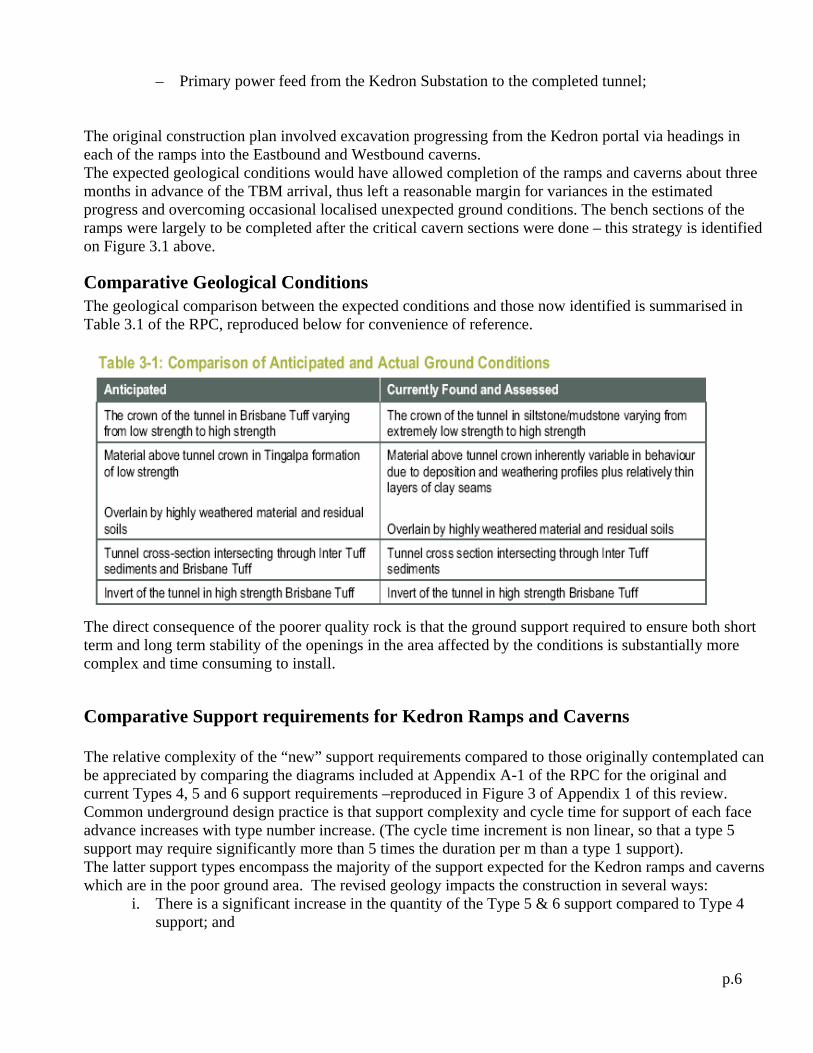
Comparative Geological Conditions The geological comparison between the expected conditions and those now identified is summarised in Table 3.1 of the RPC, reproduced below for convenience of reference.
The direct consequence of the poorer quality rock is that the ground support required to ensure both short term and long term stability of the openings in the area affected by the conditions is substantially more complex and time consuming to install.
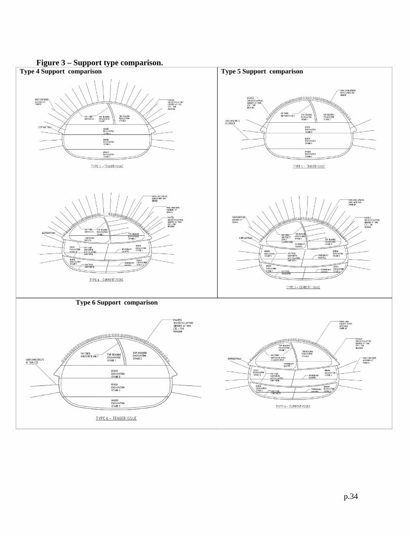
Comparative Support requirements for Kedron Ramps and Caverns The relative complexity of the “new” support requirements compared to those originally contemplated can be appreciated by comparing the diagrams included at Appendix A-1 of the RPC for the original and current Types 4, 5 and 6 support requirements –reproduced in Figure 3 of Appendix 1 of this review. Common underground design practice is that support complexity and cycle time for support of each face advance increases with type number increase. (The cycle time increment is non linear, so that a type 5 support may require significantly more than 5 times the duration per m than a type 1 support). The latter support types encompass the majority of the support expected for the Kedron ramps and caverns which are in the poor ground area. The revised geology impacts the construction in several ways:
i. There is a significant increase in the quantity of the Type 5 & 6 support compared to Type 4 support; and

p.7
ii. The revised “Type 5 and 6” supports are in fact significantly more complex than the original support types with the same type numbers, thus require longer times to install and further reduce the achievable rate of forward advance.
The rate of advance of any roadheader excavation is a function of the support complexity necessary to provide a safe and stable opening. Thus there is always an apparent anomaly – the “weaker” the ground (i.e. “softer”), the slower the progress, even though the instantaneous excavation rate may be higher in the “weaker” ground. The relative complexity of the modified support requirements is best reflected in the gross production rates measured in terms of volume excavated per week. This production measure is summarised in Table 3.2 of the RPC, reproduced below.
The increases in the quantity of the more difficult and time consuming support types is reflected in the tabulation following, which has been compiled by the author of this review from data made available by BC/TJH.
Support Type required -->
Expected Geology
Revised geology
Expected Geology
Revised geology
Ramp B 448 102 205 560Ramp C 115 120 199 201Ramp D 260 90 305 340WB Cavern 184 60 0 130EB Cavern 404 90 0 320
* Design drawings retain original type designations but actual details for revised geology are much more complex
ST 2 - 4* ST 5 - 6*Comments
Tabulated value = Length expected in support type, m
[Note: The apparent reduction in total supported length in the various drives comes from geometrical design improvements able to be made which allow greater use of the TBM profile section for the ramp merge]
Program Implications of the “No additional worksite” Option. As is evident from the diagrams of the support types included in Figure 3 of Appendix 1 hereto, the size of both ramps and caverns demands several passes of the roadheader irrespective of the support type involved. The upper (crown) sections are the most difficult and dangerous and control the rate of progress. Typically, working space and other practical issues require that the bench excavation lags of the order of 100m behind the heading.

p.8
The heading itself is large enough to provide access to the cavern areas, thus it is possible to delay some or all of the bench excavation of the ramps to permit earlier access to the caverns, hence earlier completion of the critical cavern sections. The heading advance will therefore control the excavation program, so direct comparison of the heading times is the primary indicator of the extra time required for completion of the ramps and caverns. As already indicated in Figure 3.1, this approach is incorporated in the TJH methodology for the ‘baseline program’. It has been retained for all subsequent programs developed to investigate the magnitude of delays associated with the changed geological conditions. The RPC includes a tabulation of the additional time estimate for construction of each of the ramps and caverns at Table 3.3 reproduced below. The addition of the ‘delay days’ as has been done in the table is a measure of the additional roadheader time required to complete all sections, but is NOT a measure of the project delay. Ramp C provides access to Ramp D, and also to the Eastbound cavern. Ramp D provides access to the Westbound cavern (refer program titled “Original GP08 Work-fronts”, RPC Appendix A.1). Thus there is a degree of overlap between the various delays of Table 3-3
The RPC does not specifically address the overall project delay that would result if the original construction sequencing and Roadheader resources were to continue to apply. However, it is obvious that the delay to completion of the Westbound (W/B) and Eastbound (E/B) caverns would be not less than the 12 months indicated slip in the cavern completion dates indicated in Table 3-4 for the comparison between the program dates given for “Original GP08 ...Work fronts” [W/B cavern. 10/07/2010; E/B cavern 20/8/2010] and “GP08 Alternative 1” [W/B cavern. 22/06/2011; E/B cavern 18/8/2011]. It can be seen from the version of GP08 Original program reproduced as Figure 3.2.b hereafter that the cavern completion dates had about 3 months float relative to the ‘Must be completed by’ arrival date of the TBMs at each of the W/B and E/B caverns. Since the ‘GP08 Alternative 1’ program already includes for the addition of 1 extra Roadheader spread (making 5 compared to the original 4), it is readily apparent that absent any mitigation steps, the impact of the revised geological conditions would be at least (12-3 = 9) months delay to the project opening. The program logic depicted in the Appendix A-1 “Original GP08 Work-fronts” of the RPC has been summarised in Figures 3.2.a & 3.2 .b following.

p.9
Figure 3.2.a: GP08 - Roadheader resources & Workfront locations

p.10
Figure 3.2.b: GP08 program projections with 4 Roadheaders, up to TBM arrival at W/B & E/B caverns.

p.11
4. PROGRAM RECOVERY OPTIONS
Options studied by BC/TJH The program implications discussed above have led to a number of studies by BC/TJH as to means of mitigating the unacceptable consequences referred to above. Options considered are detailed at some length in section 3.3 of the RPC. In summary, the options considered have included:
i. Allow the TBMs to traverse the caverns prior to completion of cavern excavation ii. Add one extra work-front and roadheader on Ramp B. iii. Add two extra work-fronts and roadheaders on Ramp B and Eastbound cavern. iv. Rose Street Access shaft plus three extra work-fronts and roadheaders on Ramp B, eastbound and
westbound caverns. v. DES Access shaft option plus three extra work-front and roadheaders on Ramp B, eastbound and
westbound caverns. vi. Melrose Park Access shaft plus three extra work-front and roadheaders on Ramp B, eastbound and
westbound caverns.
Each of the above are briefly explained below.
Option (i): TBMs to traverse caverns prior to completion by Roadheaders This option would allow the TBMs to proceed through the cavern area prior to its completion, hence at first glance, avoid the TBM delay. The RPC deals with this as follows:
While this technique is relatively simple with the appropriate TBMs, the adverse ground conditions encountered between Kedron and Clayfield for Airport Link require a different type of TBM (i.e. Earth Pressure Balance – EPB - style single shielded segment machines).
The “adverse ground conditions” referred to in this comment are those which were known to exist from the project initiation over a section of the drive between the Clayfield and Kedron areas because of the different geology in that section. Those conditions dictated the use of the type of machine chosen by TJH. They involve geological conditions quite different from those affecting the Kedron ramps and caverns. A single shield machine operates by excavating a length equal to the length of the precast segments installed within the shield immediately behind the face (segment length of the order of 2 to 2.4m for this diameter), then installing the segment ring, then jacking off the completed ring to excavate the next segment length. The segment rings are progressively backfilled with pea-gravel and cement grout as they emerge from the shield, thus creating a continuous concrete lining behind the TBM as it advances. The lower half of the circular profile is below final road level so is progressively backfilled behind the rear of the TBM “backup train”, which incorporates the multitude of services and supply activities necessary to support the TBM operations. In the case of passing through an already excavated and supported cavern, the caverns are only excavated to final roadway level (or slightly below if invert struts are need as part of the initial cavern support system), so segments are only installed in the lower half of the ring (i.e, below final road level). This is

p.12
sufficient to provide the necessary thrust reaction for forward advance and the crown section has already been made safe by the previous roadheader operation. The RPC further notes in respect of this option that:
.The use of this type of TBM to cut through a partially excavated cavern would introduce additional safety risks for the tunnelling crews. The measures required to mitigate the safety risks in turn would delay progress of the TBMs through the caverns. Once a TBM had traversed an incomplete cavern, the supply systems for the TBM (conveyor, services, etc) would essentially quarantine the cavern from the works necessary to complete the cavern excavation until the TBM work was complete. In summary, this option does not assist in mitigating delays to the completion of the Project.
The TBM “back-up” train carries the entire infrastructure necessary to support the operation except the muck removal conveyor extensions, ventilation extensions, and water and power extensions – all of which extend back through the completed tunnel to the starting point of the TBM operation. The backup train will be of the order of 150m-200m length. It must be fed by road trains supplying segments, invert culvert sections, grout and segment backfill materials, and a multitude of ancillary materials. Once the TBM passes through the cavern, the muck removal conveyors, ventilation and water and power extensions will remain in use until the TBM completes at Lutwyche (the Chalk street shaft). Road traffic within the completed section of TBM tunnel must continue to service the TBM with segments, invert culvert sections, etc. There will be little or no opportunity to undertake the complex excavation and support that would be required were the precast lining to be partially removed and the cavern widened and support installed for its final geometry. Thus the statement quoted above from the RPC is considered to be very much an under statement. The reviewer agrees that this option does not assist in mitigating delays to the completion of the Project. It should be noted that the Northbound and Southbound caverns on the layout diagram are accessed from the Chalk Street worksite, thus these caverns will be completed well before needed. Once these are sufficiently advanced, a new heading can be opened up driving Ramp B from the southern end (ramp bottom) in parallel with the heading being advanced from the upper (crosscut C2) end. This is alternative (ii) of the options above. It reduces the delays to Ramp B, but as can be seen from the tabulation in the section below, achieves little by way of improving the outcome for the critical Eastbound and Westbound caverns.
Options ii to vi: Increased resources with existing access &/or alternative access via new shafts. Each of these options is discussed in the RPC with comparative programs provided in Appendix A-1 and an outcome summary at Table 3.4. The table following has been produced using the data of Table 3.4 in combination with the programs of Appendix A-1. The comparative delays resulting from the various options have been added as an additional column. The critical factor is to achieve initial excavation and support of the merge caverns prior to arrival of either of the two TBMs, progress of which is critical to the overall completion date of the Airport Link project. In essence, each of these options involves the introduction of additional road-header resources, and, in the case of the shaft options, addition of a completely new work front by the sinking of a shaft to gain access to the eastern end of the eastbound and westbound caverns to allow excavation and support of these to proceed from both the west and east ends simultaneously. This effectively halves the cavern excavation period without prejudicing the safety of any of the underground options. In the final analysis, any option which does not preserve the high level of workplace safety that is imperative in any underground operation can not be contemplated.
p.13
Options ii and iii involve only the addition of extra roadheader workfronts by modifying the sequence of the access arrangements commencing from the principal access to the Kedron ramps via Ramp C and utilising the Chalk Street site to gain access to the southern end of Ramp B and drive northwards while the drive from the northern end advances towards the south. The work sequence logic and program outcomes resulting from option iii are reproduced in figures 3.3.a and 3.3.b following. This still results in an overall projected delay of the order of seven to eight months. In the reviewer’s opinion, option iii represents the maximum benefit likely to be gained without the addition of a completely new access point to the Eastbound and Westbound caverns. In practical terms, any such new worksite will involve a major roadheader operation based upon development of a shaft to access the appropriate cavern area from the shaft well in advance of the time possible from the original ramp accesses.

p.14
Figure 3.3.a Underground sequencing logic to achieve six (6) Roadheader workfronts from original Kedron & Chalk St access points

p.15
Figure 3.3.b: Program projections with six (6) Roadheaders, up to TBM arrival at W/B & E/B caverns.

p.16
The table below has been produced using the program projections of the RPC Appendix A-1 together with the contents of Table 3-4 of the RPC.
Mitigation Strategy Outcome ProjectionsProgram (Status/ Version) Start of
ramp CComplete W/B cavern ( Excavation only)
Complete E/B cavern (Excavation only)
Complete Balance of Mined Tunnels (Excavation, Pavement & Lining)
Resource Implications
Westbound EastboundLatest Dates caverns required for TBMs 01/10/10 23/11/10 01/10/10 23/11/10
Figs 3.2.a & 3.2.b
Original GP08 (original tender document) Workfronts
17/07/2009 10/07/2010 20/08/2010 30/08/2011 4 Roadheader workfronts required for original expected geotechnical conditions <2.8> <3.2> <3.0>
GP08 Alternative 1 (impact of actual geology)
7/07/2009 22/06/2011 18/08/2011 22/08/2012 One extra Roadheader heading added to drive Ramp B back from Chalk Street in parallel with drive from N end of Ramp B (total 5 Roadheader headings)
8.8 8.9 8.9
Figs 3.3.a & 3.3.b
GP08 Alternative 2 (impact of actual geology)
7/07/2009 22/06/2011 20/05/2011 22/05/2012 Additional Roadheader heading added to Alternative 1, via access created from Westbound cavern at crosspassage 30 to northern third of eastbound cavern (total 6 Roadheader headings)
8.8 5.9 7.4
Figs 3.4.a & 3.4.b
Rose Street Access shaft 7/07/2009 4/09/2010 8/10/2010 27/10/2011 Provide new access via shaft to N end of Eastbound and Westbound caverns withtwo additional Roadheader headings based on Rose Street shaft and Alternative 1 extra heading for Ramp B progressing from Chalk St.
<0.9> <1.5> <1.2>
DES Access shaft option 7/07/2009 26/05/2011 17/03/2011 8/03/2012 Equipment as Rose Street option, but with considerable length of access drive to reach the tunnel alignment
7.9 3.8 5.9
Melrose Park Access shaft option
7/07/2009 6/05/2011 12/02/2011 17/02/2012 Equipment as Rose Street option, but with considerable length of access drive to reach the tunnel alignment
7.2 2.7 5.0
Note 1:
Note 2: The delays included in the tabulation above are based on activity completion dates included in RPC Table 3-4. The delays identified on the referenced figures against the alternatives are based on counting of months in the program representations of RPC Appendix A-1. For present purposes, the differences are not considered significant.
Critical path Delay in months , hence probable project delay (see note 2 below table) Negative
value = NO DELAY
Mean of delays to TBMs (see note 1
below table) Negative value =
NO DELAY
Cross passages, ceiling smoke ducts, underground substations, and services fitout require both TBM tubes complete to be significantly progressed. Thus the overall project delay is more closely aligned with the maximum delay to either of the two TBMs than the mean delay as used in the tabulation above
It is apparent from the tabulation above that none of the practical options can approach the original completion date unless both the following are provided:
o additional workfronts utilising additional resources, and o a new access point to allow effective utilisation of some of the additional resources.
The new access point permits new workfronts to be opened up to drive back from a point near the extremity of the cavern driveage and meet the original Roadheader drives as they advance forwards, thereby substantially reducing the length each independent heading is required to advance in the essentially fixed time period available before the TBMs arrive at the Westbound and Eastbound caverns. The difference between the three shaft options considered (i.e., options iv, v and vi) is essentially the length of access drive required from the base of the shaft to the cavern alignment. As the access drive is

p.17
temporary works only, it must also be backfilled when no longer required, which adds further expense (although a non-critical activity). These differences are evident from the diagrams included with each of the option programs included in Appendix A-1 of the RPC. The Rose Street site is almost directly over the alignment and requires only a short length of temporary access drive to reach the main alignment whereas each of the other two shaft options involve considerable lengths of additional temporary access drive to reach the tunnel alignment. In the reviewer’s opinion, the Rose Street option is the only available option that has a reasonable chance of achieving the original completion date. The next best program option would appear to be the Melrose Park shaft, which would mean somewhere between five (5) months delay (the mean value) and seven (7) months delay (the maximum delay to the Westbound TBM) to the project for a similar expenditure at surface level and a greater expenditure underground because of the added drive length. It would also involve exposure of the communities around the existing worksites for longer periods, as follows:
o the Kalinga Park portal at Clayfield : at least 7 months (TBM conveyor & spoil disposal system must remain in place until both TBMs are complete);
o the Kedron portals : at least five months (minimum overall project delay); o the Chalk Street worksite precinct: at least 7 months (removal of last TBM); o Bowen Hills worksite – (not considered in detail, but some delay inevitable).
In addition, the Brisbane community as a whole will be impacted because of the delay to commencement of the tunnel operation. The work sequence logic and program outcomes resulting from the Rose Street shaft option are reproduced in figures 3.4.a and 3.4.b following. [note that the sequence diagram included in the RPC, Appendix -1 for this option, Appears to have incorrectly coloured the segment of Westbound cavern work undertaken by RH 7. The diagram of Figure 3.4.a has rectified this perceived error.]

p.18
Figure 3.4.a Underground sequencing logic to achieve seven (7) Roadheader workfronts from original Kedron & Chalk St access points plus proposed Rose Street shaft addition.

p.19
Figure 3.4.b Program projections with seven (7) Roadheaders and Rose Street shaft addition, up to TBM arrival at W/B & E/B caverns.

p.20
5. SPECIFIC CONSTRUCTION ASPECTS of the ROSE STREET SHAFT OPTION
Proposed Site Location The proposed location within the general urban area is indicated in several places in the RPC including ‘Figure 2-3, Local Area’ and ‘Figure 2-6, Existing Land Uses’. The latter two diagrams are reproduced as Figure 4 of Appendix 1 of this report. The proposed shaft and worksite is on vacant land owned by the State, fronting onto Rose Street between Park Rd and Kent Street – see diagram following from the RPC. .
Site Establishment and setup Extensive noise modelling has been undertaken by BC/TJH which is reported in detail in sections 5.3 and Appendix A.3 of the RPC. Based on prior experience with similar shaft setups in urban areas, TJH assumed from the outset that it would be necessary to construct a large acoustically lined shed over the shaft work area to meet the noise standards required by the existing Coordinator-General’s conditions. The modelling has considered 3 stages of activity at the Rose Street worksite:
Stage 1 – site set up and shaft sinking through upper 20m of overburden in parallel with acoustic shed construction.
Stage 2 –shaft excavation beyond depth of 20 m with hydraulic hammer in parallel with ongoing acoustic shed construction;
Stage 3 – site operation with acoustic shed constructed (roadheader excavation and tunneling operations associated with permanent underground development).
In summary, it has been determined that in order to achieve the noise standards to be met by the construction operations required at the Rose Street worksite, it will be necessary to set up the site facilities to the following standard:
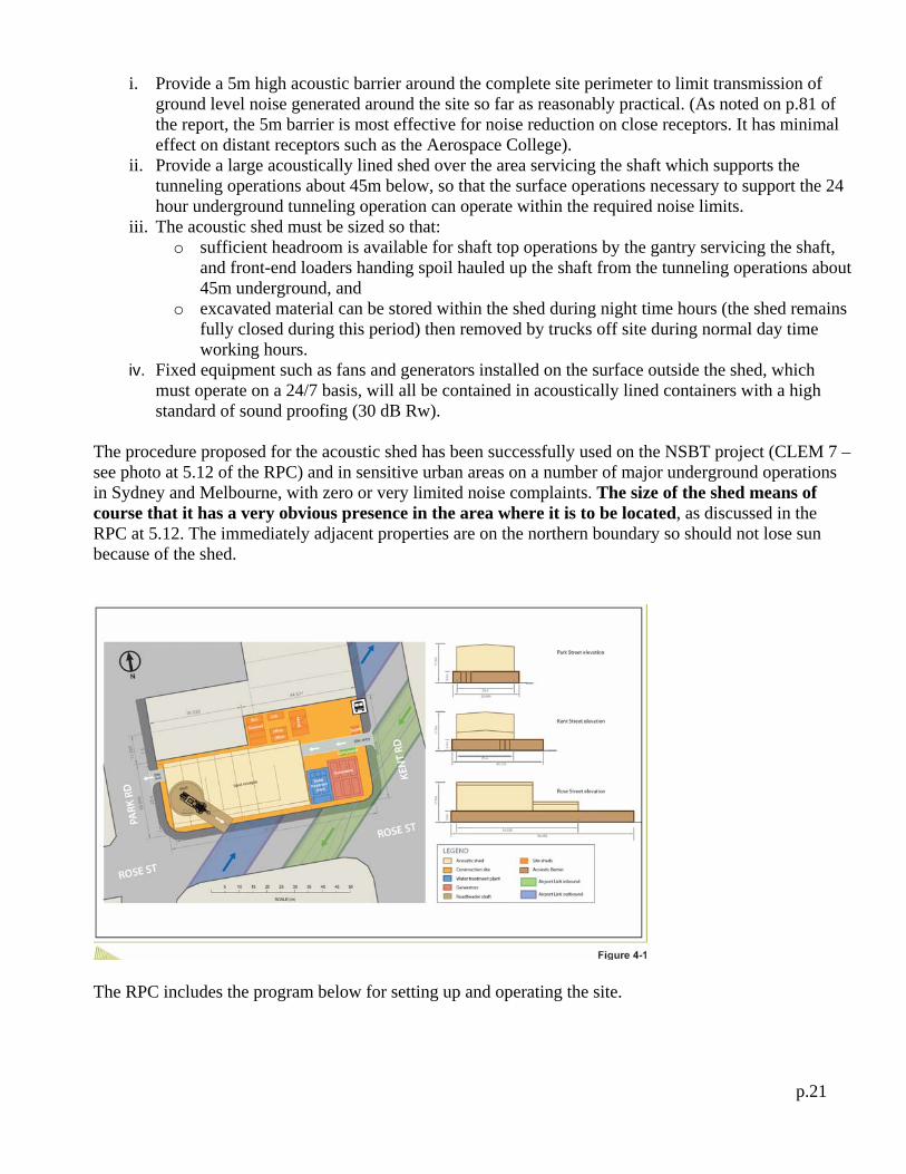
p.21
i. Provide a 5m high acoustic barrier around the complete site perimeter to limit transmission of ground level noise generated around the site so far as reasonably practical. (As noted on p.81 of the report, the 5m barrier is most effective for noise reduction on close receptors. It has minimal effect on distant receptors such as the Aerospace College).
ii. Provide a large acoustically lined shed over the area servicing the shaft which supports the tunneling operations about 45m below, so that the surface operations necessary to support the 24 hour underground tunneling operation can operate within the required noise limits.
iii. The acoustic shed must be sized so that: o sufficient headroom is available for shaft top operations by the gantry servicing the shaft,
and front-end loaders handing spoil hauled up the shaft from the tunneling operations about 45m underground, and
o excavated material can be stored within the shed during night time hours (the shed remains fully closed during this period) then removed by trucks off site during normal day time working hours.
iv. Fixed equipment such as fans and generators installed on the surface outside the shed, which must operate on a 24/7 basis, will all be contained in acoustically lined containers with a high standard of sound proofing (30 dB Rw).
The procedure proposed for the acoustic shed has been successfully used on the NSBT project (CLEM 7 – see photo at 5.12 of the RPC) and in sensitive urban areas on a number of major underground operations in Sydney and Melbourne, with zero or very limited noise complaints. The size of the shed means of course that it has a very obvious presence in the area where it is to be located, as discussed in the RPC at 5.12. The immediately adjacent properties are on the northern boundary so should not lose sun because of the shed.
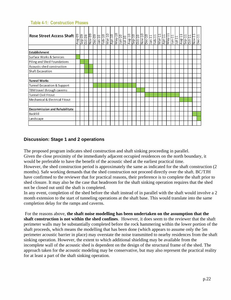
The RPC includes the program below for setting up and operating the site.
p.22
Discussion: Stage 1 and 2 operations
The proposed program indicates shed construction and shaft sinking proceeding in parallel. Given the close proximity of the immediately adjacent occupied residences on the north boundary, it would be preferable to have the benefit of the acoustic shed at the earliest practical time. However, the shed construction period is approximately the same as indicated for the shaft construction (2 months). Safe working demands that the shed construction not proceed directly over the shaft. BC/TJH have confirmed to the reviewer that for practical reasons, their preference is to complete the shaft prior to shed closure. It may also be the case that headroom for the shaft sinking operation requires that the shed not be closed out until the shaft is completed. In any event, completion of the shed before the shaft instead of in parallel with the shaft would involve a 2 month extension to the start of tunneling operations at the shaft base. This would translate into the same completion delay for the ramps and caverns. For the reasons above, the shaft noise modelling has been undertaken on the assumption that the shaft construction is not within the shed confines. However, it does seem to the reviewer that the shaft perimeter walls may be substantially completed before the rock hammering within the lower portion of the shaft proceeds, which means the modelling that has been done (which appears to assume only the 5m perimeter acoustic barrier in place) may overstate the noise transmitted to nearby residences from the shaft sinking operation. However, the extent to which additional shielding may be available from the incomplete wall of the acoustic shed is dependent on the design of the structural frame of the shed. The approach taken for the acoustic modeling may be conservative, but may also represent the practical reality for at least a part of the shaft sinking operation.

p.23
The BC/TJH noise modelling indicates the EIS conditions are met at ground level for all initial site setup operations with the 5m acoustic screen. However, with barrier doors (‘gates’) open, exceedances of the adopted noise goals at first floor level of close receptors are predicted unless the doors for the perimeter noise barrier remain closed. Such a condition cannot be enforced all the time because delivery vehicles must come and go. As noted above, if the perimeter walls of the acoustic shed are largely in place, both ground level and first floor noise exceedances would appear likely to be significantly reduced relative to the modelling reported in the RPC. During shed construction, Table 5.7 indicates the LA10 noise limits (i.e. noise limits that are likely to be exceeded 10% of the period in question) are likely to be exceeded at 3 residences. The perimeter of the shaft is proposed to be constructed with overlapping bored piles (otherwise called secant piles). This operation is little different to the foundation piling required for any significant residential apartment block. The RPC notes that this activity is not expected to cause either noise or vibration difficulties, and the reviewer is of the same view. An exploratory borehole on shaft centreline indicates the first 20 to 25 m of the shaft should be easily excavated by a large backhoe. Again, this activity is little different to the basement excavation of commercial developments in overburden or soft rock, and the acoustic modelling indicates this operation should not result in any major disturbance to the adjacent properties. The section of shaft below about 25 m is likely to require mechanical breaking with hydraulic rock hammers. Hammering hours per metre of advance will increase with depth because the rock becomes increasingly stronger with depth. On the positive side, vibration and emitted noise will diminish with depth. Given normal expected production rates of about 6-8 m3/hr from rock hammering in a shaft of this size, the lower 20m in rock is likely to require between 400 and 500 elapsed working hours. The operations involve repeated cycles comprising breaking out by hammering, then loading and hoisting the broken rock to the surface, then installing rock support as necessary in the newly exposed base region of the shaft, then repeating the cycle. The elapsed duration in days for the shaft sinking will depend on the permitted hours for rock hammering. The RPC proposes hammering between 06:30-18:30 hours. Assuming 1 hr per day out for lunch and crib breaks, this would translate to about 1.5 to 2.0 days per m of advance, or between 30 and 40 days to bottom out. Assuming 6 day working and allowing for piling and excavation of the upper half of the shaft, this estimate would be consistent with the TJH indicated program. If hammering hours were to be restricted to less than the window above, the sinking time will be proportionately increased. The RPC states that: when the acoustic shed is able to provide the requisite noise screening, the working hours shall be extended to permit activities such as shaft excavation to be carried out. For the reasons set out above, it seems unlikely to the reviewer that any significant portion of the shaft will be constructed under the protection of the acoustic shed. The acoustic modelling for the rock hammering has been undertaken on the assumption that the acoustic shed would not be in place. The standard adopted was the LA10 requirement, (being the limit only exceeded 10% of the time). The tabulation presented at Table 5.9 of the RPC indicates that with the 5m barrier in place, the LA10 standard will be exceeded at 2 residences. As I have noted, assuming the perimeter wall of the acoustic shed is largely in place, it seems probable that the modelling overestimates the noise impact during shaft sinking for at least a portion of the sinking operation.
p.24
The other aspect of rock hammering will be vibration. This is dealt with in the RPC at 5.4.2, p. 99, as follows:
The level of vibration measured at the adjacent properties would be dependent upon hammer energy and the distance between the hammering location and the point of measurement. Measurements from other similar Project areas indicate that the level of vibration would be at a maximum at the rock interface (estimated to be 20 m below the collar) in the range of 0.5 m to 1 mm/s. Vibration levels of this magnitude would be perceptible to persons within the nearest properties, although levels are expected to be within the compliance values specified in the Coordinator-General’s conditions.
Blasting: The likelihood of blasting being required during shaft sinking seems low. It is noted as an emergency method in case extremely hard rock is encountered. While some blasting has apparently been undertaken at the southern portal area, it would seem wise for some small scale trial blasts be undertaken in advance of the shaft excavation advancing below about 20m depth, in case some blasting is required at Rose Street. Vibration projections are based on empirical formulae, and it is desirable to “calibrate” the ground to more accurately predict transmitted vibration levels. The peak particle velocity regime (ppv) already included in the existing project approval requirements is considered conservative, but advance trials would ensure that any initial production blasts that may be required will meet the prescribed standard. If blasting should be required, explosives should be stored in an offsite magazine and the amount kept on site at any time limited to day use only. If not used, the excess should be returned to the off-site storage magazine. Discussion of this subject with BC/TJH indicates that this is their intention, which is why explosives is not mentioned in their list of “hazardous materials” to be stored on site. Summary: Stage 1 and 2 operations It seems probable that TJH may have to make some arrangements with several of the surrounding residences during the shed construction period and the shaft sinking period in accordance with the existing Coordinator-General’s conditions (“Proponent is required to implement mitigation measures and undertake consultation to manage the impact on potentially affected residents”).
Discussion : Stage 3 operation
Day time Operational Noise The majority of construction activity will be within the limits of the acoustic shed, but the doors will be opened to allow vehicles to enter and leave. As noted in Section 6 following, during the two months of peak spoil haulage operations, trucks will be leaving and entering on an average 11 minute cycles, so in practice both the acoustic shed doors and the 5m perimeter barrier ‘gates’ will have to remain open for a significant portion of each day during that peak period. There will be inevitable fluctuations in vehicle arrival and departure frequency, so conditions requiring that doors remain closed in other than peak period vehicle frequencies could be reasonably imposed. Table 5.12 of the RPC records that only one residence will be exposed to noise levels above the

p.25
LA10 limit. Based on Table 5.11, the exceedance would appear to be only 1dB above the limit (65 permitted, 66 modeled). For practical purposes, this should be readily negotiable between TJH and the affected residence.
Night-time Operational Noise General operations through night-time hours (proposed by BC/TJH to be between 18:30 and 06:30 the following day) are to proceed with the acoustic shed doors closed. It is proposed that tunnel spoil excavated through the nightshift will be stored within the shed and spoil haulage off site will be limited to between 06:30 in the morning and 18:30 in the evening. The noise modelling summarised at Tables 5.11 and 5.12 of the RPC indicates that construction operations undertaken within acoustic shed meet the existing noise conditions for night-time operation provide the acoustic shed doors remain closed. The fans and generators located outside the shed were modelled assuming Rw 20 dB enclosures. This standard does not achieve the required noise results, there being 31 residences where the LA eq standard is exceeded with that assumption. As noted at p.88 of the RPC, it will be necessary provide silencers on the fans to achieve 12dBA reduction and to increase the rating of the enclosures for generators and compressors from Rw 20dB to Rw 30 dB to meet the required standard. It is noted that with those adjustments, predictions show that the night-time LAeq noise goal would be achieved. The reviewer is of the opinion that the improvements noted are both practical and reliably achievable. There is one exception to achievement of the night-time standards. The RPC notes at 5.3, p. 87, that
There is a potential for a maximum of four shotcrete trucks to make deliveries between the hours of 18:30 and 06:30. The night-time maximum noise level goal would be exceeded during such events.
The need for shotcrete undoubtedly arises from the support requirements of the ramps and caverns – refer Figure 3 of Appendix 1 hereto. It is inevitable that with the support types indicated and a 24 hour underground operation, shotcrete applications will arise randomly throughout any 24 hour period. Since the unsupported face advance is limited to between 1 and 1.2m, the amount of shotcrete required can be reasonably calculated. However, safety demands that it be applied as soon as the face is excavated, hence the need for shotcrete to be available on call at any time within the 24 hour period. This fact is noted at RPC p.88. It is probable that any shotcrete requirement will involve several deliveries spaced about 20-30 minutes apart. The RPC further notes5 that by the addition of suitable set retarders, it would be possible to limit deliveries to site within the hours of 18:30 to 22:30, hence “concrete deliveries beyond 22:30 are not planned to occur.” The reviewer is not aware of retarders that may delay set to the extent necessary to guarantee their use would result in shotcrete availability whenever likely to be needed during the period 22:30 to 06:30. However, given that it has been offered, a condition precluding shotcrete deliveries after 22:30 would seem to be in order. Summary: Stage 3 operations:
5 Executive Summary, p.12; Appendix A-2, Work Method Statement, p.15/38.

p.26
i. Day-time construction operations may produce some exceedances of the LA10 limit at the closest residence. The one most likely to be affected is that immediately adjacent to the site exit onto Park Rd. The predicted LA10 noise level according to the modelling results included in the RPC is only marginally above the approved level, so it would seem possible for the level of exceedance to be negotiated with the affected residence(s).
ii. Night-time construction operations will meet the required LAeq standard most of the time provided operations proceed with the acoustic doors remaining closed, additional silencing of ventilation fans is provided, and acoustic enclosures for the main externally located generators and compressors meet an Rw 30 dB standard. The exceptions to meeting the standard involve the possibility of up to four loads of shotcrete being delivered between the hours of 18:30 and 06:30. The reviewer is of the opinion that this event will be largely random, and difficult to predict with any accuracy in advance of each night shift. The RPC has offered to accept no shotcrete deliveries after 22:30, which would limit any community inconvenience due to this fairly random activity.
6. COMMUNITY ISSUES
Spoil Haulage The program for the underground work accessed from the Rose Street shaft indicates a progressive increase in material removed over the period of underground development. This simply reflects the fact that as the development expands away from the shaft base, so additional work faces can be added. Figure 4.4 of the RPC (reproduced below) indicates the expected volume that will be removed from commencement of underground excavation at the shaft base according to the program production estimates. (The Y axis of the figure is in working days). .

p.27
From a community impact point of view, it is the number of trucks per day that is of significance. The RPC refers to approximately 9,000 truckloads assuming a solid density of 2.3 Te/m3. From the reviewers experience, this density is more likely to be low than high, but the difference in truck loads is not considered significant. Adopting 2.3 te/m3 as the relevant figure, Figure 4-4 has been used to produce a chart of both volumes by period and truck loads by date period, as below. Date periods are based on the Rose street shaft program included in the RPC and reproduced section 5 above.
TRUCK HAULAGE REQUIREMENTS PER WORKING DAY AS PROGRAM PROJECTIONS
0
100
200
300
400
500
600
700
800
900
1000
1100
1200
1300
1400
1500
14-O
ct-0
9
03-D
ec-0
9
22-J
an-1
0
13-M
ar-1
0
02-M
ay-1
0
21-J
un-1
0
10-A
ug-1
0
29-S
ep-1
0
18-N
ov-1
0
Notional date, assuming 1 Dec 09 haulage start
Solid
m3
rem
oved
per
day
as
prog
ram
pr
ojec
tions
0
10
20
30
40
50
60
70
80
90
100
No.
of B
-dou
ble
truc
k lo
ads
off s
ite p
er w
orki
ng
day
Daily quantity in Solid m3 No. of B-double trucks per day; (32te loads @ 2.3 te/m3)
The maximum daily haulage amounts to about 65 trucks. Assuming the RPC haulage window of 06:30 to 18:30, this equates to one B-double truck entering and leaving the site on an average 11 minute cycle. For the first six months of the shaft operation, the intensity of truck movements would be less than half this figure (about 30 loads per day, on an average 24 minute cycle). The intensity then progressively builds over the period May through June, reaching the maximum over about a 2 month period (late June 2010 to mid August 2010). This variation in load out volumes is referred to in the RPC in section 4.5.2. Various haulage routes have been analysed by BC/TJH. The preferred route is discussed in section 5.2.1 and identified at Figure 5-1, reproduced below. The key points relative to the proposed route would appear to be:
The proposed route:
o uses State-controlled roads and arterial roads only.

p.28
o is a one-way circuit east along Rose Street and Junction Road to Sandgate Road, returning via Rode Road, Gympie Road, Kedron Park Road, Park Road, Rose Street to Kent Road.
Alternative arrangements are proposed6 to bypass construction traffic around the oversaturated intersection of Sandgate Road and Junction Road during the a.m. peak, thereby avoiding impact on that intersection.
o The haul route may require a reconfiguration of the traffic island located at the intersection of Park Road and Rose Street, to accommodate the swept path of construction vehicles leaving the proposed worksite7.
It is noted at section 5.2.2 that: During the AM and PM peak periods, additional construction vehicles, including spoil haulage vehicles, represent between a 1% and 3% increase to existing AADT (daily traffic) volumes. This increase is less than the normal variation in traffic flows and therefore the impact to traffic operations along Junction Road and Rose Street is considered negligible in terms of daily traffic flows. It is also noted at 8.3 of the RPC that it is recommended that a condition be applied covering haulage past the nearby Kedron State High School drop off zone, as follows:
during school drop-off and pick-up times (being 7:30am to 9.00am and 2.30pm to 4:00pm, Monday to Friday on school days) only where traffic control measures, including without
6 Refer RPC, section 5.2.1, p. 69. 7 Reconfiguration to be in compliance with Road Planning and Design Manual requirements for use as a pedestrian refuge
island.

p.29
limitation appropriately qualified pedestrian controllers and traffic controllers, are in place to manage pedestrians and traffic flows in and around Kedron State High School.
The reviewer is of the opinion that this is a sensible safeguard.
Workforce Numbers The construction workforce operating from the Rose Street shaft will be significant. The expected numbers are identified in Table 4-2 of the RPC, as below.
BC/TJH have recognised the potential impact of this by proposing as follows (RPC, p. 72):
Car parking for the proposed Rose Street workforce would be provided at the Kedron worksite. The workforce would be transported to and from the proposed worksite via a dedicated Project shuttle bus only. Drop-offs and pick-ups would occur within the boundaries of the worksite. No private vehicle access or car parking on the site or in nearby local streets would be permitted by the contractor.
7. SUMMARY- POSITIVE AND NEGATIVE ASPECTS of the ROSE STREET SHAFT OPTION
Positive Aspects The major positive aspect of the Rose Street option is that it appears to be the only option which presents a reasonable probability that the project will be able to complete within the original time frame. This means that the benefits of the project to the Brisbane traffic network and hence the community as a whole will be available when expected. Additional local benefits will accrue to those areas where worksites have already been approved and established. Without the Rose Street option, all these work sites will need to continue in operation for the added length of time required to complete the project.
Negative Aspects In a situation such as has arisen here, it is inevitable that some part of the community will be exposed to inconvenience that was not contemplated at the outset of the project.

p.30
The obvious factors that arise around the Rose Street site are noise, vibration and traffic. The RPC includes professional studies undertaken on behalf of BC/TJH covering all these issues at some length. The studies have confirmed that with a few exceptions, all of the original EIS conditions relating to noise and vibration can be met. The acoustic structure that must be constructed at Rose Street to achieve the conditions is large and visually unattractive. Apart from choosing an exterior colour that avoids glare, there would not appear to be any obvious ways to make it attractive. Traffic studies have been undertaken to reduce the impact of the truck concentration associated with the construction activities, but some inconvenience would seem inevitable. G M Peck 20 July 2009 Revised 30 July 2009

p.31
Appendix 1 – Figures 1 to 4
p.32
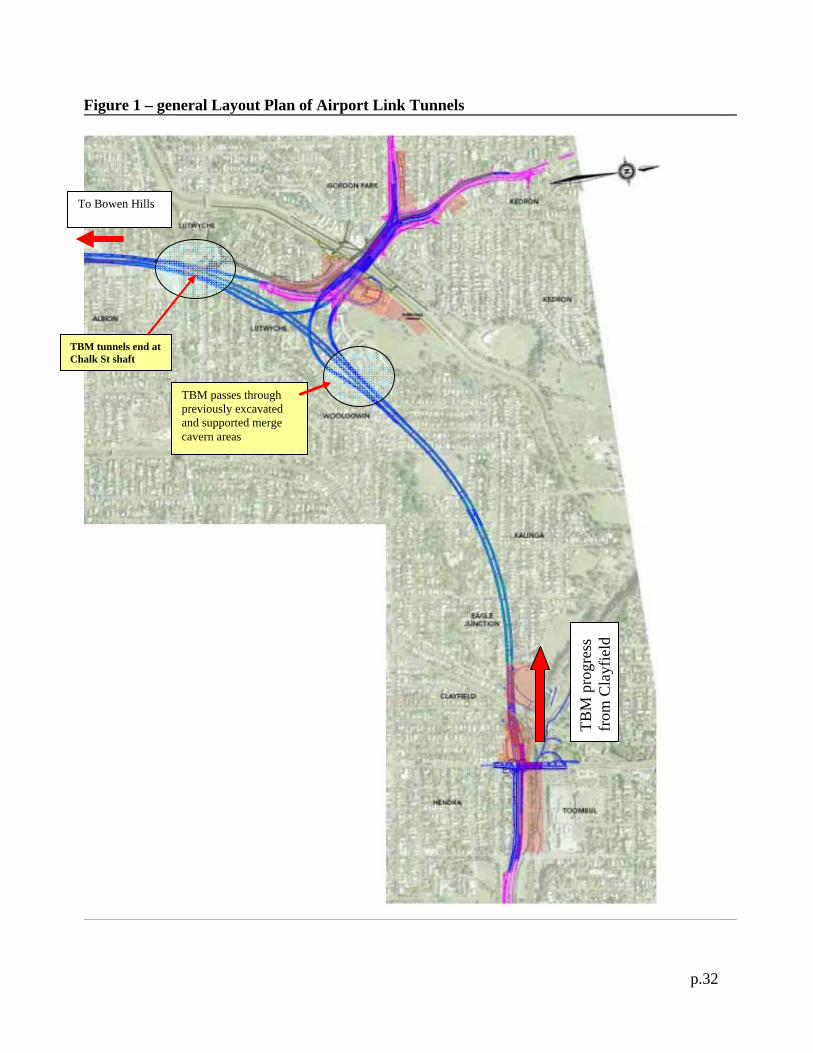
Figure 1 – general Layout Plan of Airport Link Tunnels
To Bowen Hills
TBM
pro
gres
s fr
om C
layf
ield
TBM passes through previously excavated and supported merge cavern areas
TBM tunnels end at Chalk St shaft

p.33
Figure 2 - Boreholes available at Offer Time
p.34
Figure 3 – Support type comparison.
Type 4 Support comparison
Type 5 Support comparison
Type 6 Support comparison

p.35
Figure 4 – Neighbourhood features around Rose Street shaft location