
QUATTRO Column Formwork - PERIe4a67982-35a8-46f4-9c2b-5b8ba4c915c1/... · PERI products have been...
38
Issue 11 | 2016 QUATTRO Column Formwork Instructions for Assembly and Use – Standard Configuration
Transcript of QUATTRO Column Formwork - PERIe4a67982-35a8-46f4-9c2b-5b8ba4c915c1/... · PERI products have been...

Issue 11 | 2016
QUATTROColumn Formwork
Instructions for Assembly and Use – Standard Configuration

1
Overview
QUATTRO Column1 QUATTRO Frame QES2 Frame Spanner QUATTRO QA3 Brace Connector QUATTRO QR4 Eyebolt M20 x 1105 Chamfer Strip QDL6 Bolt Ø 20 x 1407 Transportation Wheel
QUATTRO
Concreting Platform, Complete11 Concreting Landing12 Platform Guardrail 134 or 5213 Crane Hook Concreting Platform14 Cam Nut DW 1515 Platform Front Guardrail 86/86
Access Ladders21 QUATTRO Lader Connector-222 End Ladder 180/223 Ladder 180/624 Ladder Hook25 Ladder Base26 Ladder Safety Cage 7527 Ladder Safety Cage 150
Main Components
QUATTRO Column FormworkInstructions for Assembly and Use – Standard Configuration
111513
14
12
22
23
27
26
242125
7
1 4
6 2
3
5

Content
Overview Main Components 1 Key 2 Presentational Reference 2
Introduction Target Groups 3 Additional Technical Documentation 3 Intended Use 4 Instructions on Use 4 Cleaning and Maintenance Instructions 5
Safety Instructions Cross-System 6 System-Specific 7 Storage and Transportation 7
Assembly and DismantlingA1 Storage and Transportation 8
Moving on the Construction Site 8
A2 Cleaning 9
A3 Assembly Preparation 10 Assembly 11 Extending at the Bottom / Extensions 12 Push-Pull Props 13 Concreting Platform 14 Parts List for Access Ladders 14 Access Ladders 15 A4 Shuttering Placing the Formwork 16 Closing the Formwork 17
A5 Striking, Moving 18
A6 Adjusting Column Cross-Section 20
Components Components 22
QUATTRO Column FormworkInstructions for Assembly and Use – Standard Configuration

2
Overview
Dimension specificationsDimensions are usually given in mm. Other measurement units, e.g. cm, are shown in the illustrations.Load details are usually given in kg. Oth-er measurement units, e.g. t, are shown in the illustrations.
Conventions � Instructions are numbered with: 1. ....., 2. ....., 3. .....
� The result of an instruction is shown by:
� Position numbers are clearly provided for the individual components and are given in the drawing, e.g. 1, in the text in brackets, for example (1).
� Multiple position numbers, i.e. alter-native components, are represented with a slash, e.g. 1 / 2.
Key
Presentational Reference
The illustration on the front cover of these instructions is understood to be a system representation only. The assem-bly steps presented in these Instruc-tions for Assembly and Use are shown in the form of examples with only one component size. They are valid accord-ingly for all component sizes contained in the standard configuration.
For a better understanding, detailed il-lustrations are partly incomplete. Safety installations may not have been includ-ed in these detailed drawings, but must be used nevertheless.
Arrows
Arrow representing an action
Arrow representing a reactionof an action*
Forces
* If not identical to the action arrow.
Pictogram | Definition
Safety instructions
Note
Load-bearing point
Visual check
QUATTRO Column FormworkInstructions for Assembly and Use – Standard Configuration
3
Introduction
QUATTRO Column FormworkInstructions for Assembly and Use – Standard Configuration
ContractorsThese Instructions for Assembly and Use are designed for contractors who either
� assemble, modify and dismantle the formwork system, or
� use it, e.g. for concreting, or � who have it used, e.g. for forming operations.
Construction site coordinatorThe Safety and Health Protection Coor-dinator*
� is appointed by the client, � must identify potential hazards during the planning phase,
� determines measures that provide protection against risks,
� creates a health and safety plan, � coordinates the protective measures for the contractor and site personnel so that they do not endanger each other,
� monitors compliance with the protec-tive measures.
Target Groups
� Design Tables 2015 – Formwork and Scaffolding
� Brochures – QUATTRO Column Formwork
Additional Technical Documentation
* Valid in Germany: Regulations for Occupa-tional Health and Safety on Construction Sites 30 (RAB 30).
** Instructions are given by the contractor him-self or a competent person selected by him.
Competent personsDue to the specialist knowledge gained from professional training, work experi-ence and recent professional activity, the competent person has a reliable un-derstanding of safety-related issues and can correctly carry out inspections. Depending on the complexity of the test to be undertaken, e.g. scope of testing, type of testing or the use of certain measuring devices, a range of specialist knowledge is necessary.
Qualified personsThe scaffolding may only be assembled, modified or dismantled by personnel who are suitably qualified to do so. For the work to be carried out, the qualified persons must have received instruc-tions** covering at least the following points:
� Explanation of the plan for the assem-bly, modification or dismantling of the formwork in an understandable form and language.
� Description of the measures for safely assembling, modifying or dismantling the scaffolding.
� Designation of the preventive meas-ures to avoid the risk of persons and objects falling.
� Designation of the safety precautions in the event of changing weather con-ditions that could adversely affect the safety of the formwork system as well as the persons concerned.
� Details regarding the permissible loads.
� Description of any other risks that are associated with the assembly, modifi-cation or dismantling procedures.
� In other countries, ensure that the relevant national guidelines and regulations in the respective current version are complied with!
� If no country-specific regulations are available, it is recommended to proceed according to German guidelines and regulations.

4
Introduction
Intended Use
Technical dataPermissible fresh concrete pressure 80 kN/m².
System dimensionsFormwork height:Maximum 4.50 m, extendable in 25-cm increments.
Column cross-sections:Square or rectangular from 20 x 20 cm to 60 x 60 cm in 5-cm increments.
Product descriptionPERI products have been designed for exclusive use in the industrial and com-mercial sectors by qualified users only.
PERI QUATTRO is the column form-work designed for fast moving with one crane lift. Units can also be moved by hand using the insertable transportation wheels. In the process, all mounting parts remain attached to the formwork. Concrete surfaces with increased re-quirements can be realised thanks to the formlining that is installed from the rear. A chamfer strip should be fixed to vertical panel joints. Both square and rectangular column cross-sections can be formed through the formwork element arrangement, which is based on the windmill vane principle.
QUATTRO Column FormworkInstructions for Assembly and Use – Standard Configuration
Instructions on Use
Use in a way not intended, deviating from the standard configuration or the intended use according to the Instruc-tions for Assembly and Use, represents a misapplication with a potential safety risk, e.g. risk of falling.
Only PERI original components may be used. The use of other products and spare parts is not allowed.
Changes to PERI components are not permitted.

5
Introduction
Cleaning and Maintenance Instructions
In order to maintain the value and opera-tional readiness of the formwork materi-als over the long term, clean the panels after each use. Some repair work may also be inevita-ble due to the tough working conditions. The following points should help to keep cleaning and maintenance costs as low as possible.
Spray the formwork on both sides with concrete release agent before each use. This allows easier and faster cleaning of the formwork. Spray the concrete re-lease agent very thinly and evenly!
Spray the rear side of the formwork with water immediately after concret-ing. This avoids any time-consuming and costly cleaning operations.
When used continuously, spray the panel formlining with concrete release agent immediately after striking. Then clean by means of a scraper, brush or rubber lip scraper. Important: do not clean plywood formlining with high-pressure equipment as this could result in the formlining being damaged.
Fix box-outs and mounting parts with double-headed nails. This allows the nails to be removed easily later on, and largely avoids damage to the formlining.
Close all unused anchor holes with plugs. This eliminates any subsequent cleaning or repair work. Anchor holes accidentally blocked with concrete are freed by means of a steel pin from the formlining side.
When placing bundles of reinforcement bars or other heavy objects on horizon-tally-stored formwork elements, suita-ble support, e.g. square timbers, is to be used. As a result, impressions and damage to the formlining are largely avoided.
Internal concrete vibrators should be fit-ted with rubber caps if possible. This reduces any damage to the formlining if the vibrator is accidentally inserted be-tween the reinforcement and formlining.
Never clean powder-coated compo-nents, e.g. elements and accessories, with a steel brush or hard metal scraper. This ensures that the powder-coating remains intact.
Use spacers for reinforcement with large-sized supports or extensive areas of support, as this largely avoids impres-sions being formed in the formlining when under load.
Mechanical components, e.g. spindles or gear mechanisms, must be cleaned of dirt or concrete residue before and after use, and then greased with a suita-ble lubricant.
Provide suitable support for the compo-nents during cleaning so that no unin-tentional change in their position is pos-sible.
Do not clean components suspended on crane lifting gear.
QUATTRO Column FormworkInstructions for Assembly and Use – Standard Configuration

6
Safety Instructions
Cross-System
GeneralThe contractor must ensure that the Instructions for Assembly and Use sup-plied by PERI are available at all times and understood by the site personnel.
These Instructions for Assembly and Use can be used as the basis for creat-ing a risk assessment. The risk assess-ment is compiled by the contractor. However, these Instructions for Assem-bly and Use do not replace the risk assessment!
Always take into consideration and comply with the safety instructions and permissible loads.
For the application and inspection of PERI products, the current safety regu-lations and guidelines valid in the re-spective countries must be observed.
Materials and working areas are to be inspected on a regular basis, especially before each use and assembly, for:
� signs of damage, � stability and � function.
Damaged components must be ex-changed immediately on site and may no longer be used.
Safety components are to be removed only when they are no longer required.
Components provided by the contractor must conform with the characteristics required in these Instructions for As-sembly and Use as well, as with all valid construction guidelines and standards. Unless otherwise indicated, this applies in particular:
� timber components: strength class C24 for solid wood according to EN 338.
� scaffold tubes: galvanised steel tubes with minimum dimensions of Ø 48.3 x 3.2 mm according to EN 12811-1:2003 4.2.1.2.
� scaffold tube couplings according to EN 74.
Deviations from the standard configura-tion are only permitted after a further risk assessment has been carried out by the contractor. Appropriate measures for working and operational safety, as well as stability, are defined on the basis of this risk assessment.Corresponding proof of stability can be provided by PERI on request if the risk assessment and resulting measures to be implemented are made available.
Before and after exceptional occurrences that may have an adverse effect regard-ing the safety of the formwork system, the contractor must immediately
� create another risk assessment, with appropriate measures for ensuring the stability of the formwork system being carried out based on the re-sults,
� and arrange for an extraordinary in-spection by a competent person. The aim of this inspection is to identify and rectify any damage in good time, in order to guarantee the safe use of the formwork system.
Exceptional occurrences can include: � accidents, � longer periods of non-use, � natural events, e.g. heavy rainfall, ic-ing, heavy snowfall, storms or earth-quakes.
Assembly, modification and disman-tling workAssembly, modification or dismantling of formwork systems may only be car-ried out by qualified persons and under the supervision of a competent person. The qualified persons must have re-ceived appropriate training for the work to be carried out with regard to specific risks and dangers.
On the basis of the risk assessment and the Instructions for Assembly and Use, the contractor must create installation instructions, in order to ensure safe as-sembly, modification and dismantling of the formwork system.
The contractor must ensure that the personal protective equipment required for the assembly, modification or dis-mantling of the formwork system, e.g.
� safety helmet, � safety shoes, � safety gloves, � safety glasses,
is available and used as intended.
If personal protective equipment against falling from a height (PPE) is required or specified in local regulations, the con-tractor must determine appropriate at-tachment points on the basis of the risk assessment.The contractor stipulates the PPE to be used to prevent falling.
The contractor must � provide safe working areas for site personnel, which are to be reached through the provision of safe access ways. Areas of risk must be cordoned off and clearly marked.
� ensure stability during all stages of construction, in particular during as-sembly, modification and dismantling operations.
� ensure and prove that all loads can be safely transferred.
UtilisationEvery contractor who uses or allows formwork systems or sections of the formwork to be used, is responsible for ensuring that the equipment is in good condition.
If the formwork system is used succes-sively or at the same time by several contractors, the health and safety coor-dinator must point out any possible mutual hazards, and all work must be then coordinated.
QUATTRO Column FormworkInstructions for Assembly and Use – Standard Configuration

7
Safety Instructions
Storage and Transportation
Store and transport components ensur-ing that no unintentional change in their position is possible. Detach lifting ac-cessories and slings from the lowered components only if they are in a stable position and no unintentional change is possible.
Do not drop the components.
Use PERI lifting accessories and slings and only those load-bearing points pro-vided on the component.
During the moving procedure � ensure that components are picked up and set down so that unintentional falling over, falling apart, sliding, fall-ing down or rolling is avoided.
� no persons are allowed to remain un-der the suspended load.
Always guide pre-assembled scaffold-ing bays, scaffolding units or scaffolding sections with ropes when moving them by crane.
The access areas on the jobsite must be free of obstacles and tripping hazards, as well as being slip-resistant.
For transportation, the surface used must have sufficient load-bearing capacity.
Use original PERI storage and transport systems, e.g. crate pallets, pallets or stacking devices.
System-Specific
Retract components only when the con-crete has sufficiently hardened, and the person in charge has given the go-ahead for striking to take place.
Anchoring is to take place only if the anchorage has sufficient concrete strength.
Only use designated PERI lifting gear.
During striking, do not tear off the form-work panels with the crane.
If a storm warning is given, additional push-pull props or other bracing meas-ures are to be used and the details in the PERI design tables must be imple-mented.
QUATTRO Column FormworkInstructions for Assembly and Use – Standard Configuration

8
13
A1 Storage and Transportation
For storing and transporting,lay the four column frames QUATTRO QES on top of each other to form a stack and then store bundled together positioned on timbers. (Fig. A1.01)
When storing horizontally, a maximum of three stacks are placed on top of each other with timbers placed in be-tween.
The stack can be transported using both a forklift truck and crane.(Fig. A1.02)
Moving on the Construction Site
Unit with concreting platformAttach the 3-sling lifting gear to the three crane eyes of the concreting platform (13). (Fig. A1.03)
Fig. A1.01 Fig. A1.02
Fig. A1.03
QUATTRO Column FormworkInstructions for Assembly and Use – Standard Configuration
9
A2 Cleaning
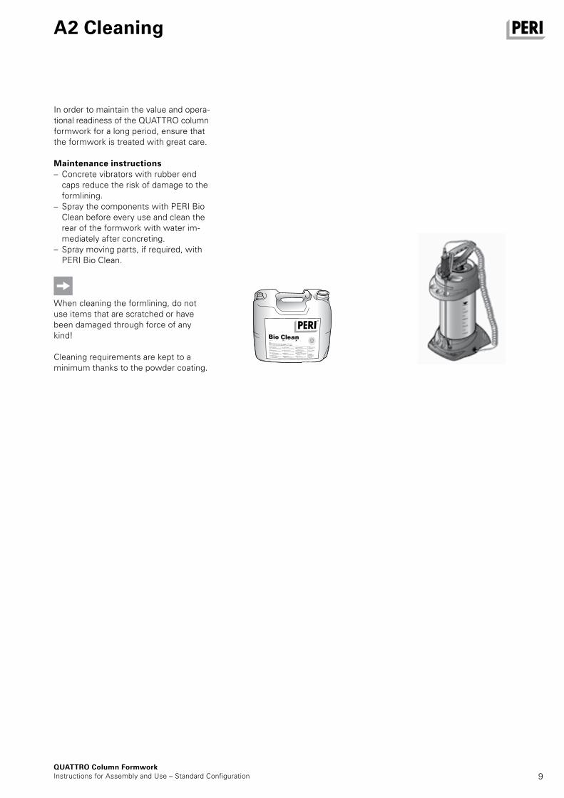
In order to maintain the value and opera-tional readiness of the QUATTRO column formwork for a long period, ensure that the formwork is treated with great care.
Maintenance instructions – Concrete vibrators with rubber end caps reduce the risk of damage to the formlining.
– Spray the components with PERI Bio Clean before every use and clean the rear of the formwork with water im-mediately after concreting.
– Spray moving parts, if required, with PERI Bio Clean.
When cleaning the formlining, do not use items that are scratched or have been damaged through force of any kind!
Cleaning requirements are kept to a minimum thanks to the powder coating.
QUATTRO Column FormworkInstructions for Assembly and Use – Standard Configuration

10
A3 Assembly
Fig. A3.01
Fig. A3.02
Preparation
Before assembly takes place, a Chamfer Strip QDL (5) must be attached to the long side of the formlining. This can be carried out when stacked. (Fig. A3.01)
The Chamfer Strip QDL is fixed with nails at approx. 15-cm spacings.
Assembly1. With the QUATTRO QES element in
a horizontal position, remove bolts Ø 20 x 140 (1.3) from the perforated walers (1.1).
2. Swivel out (1.1) the perforated waler and fix the diagonal struts (1.2) in position using the bolts Ø 20 x 140 (1.3).
3. Secure with bolts Ø 20 x 140 (1.3) and cotter pins 4/1. (Fig. A3.02)
QUATTRO Column FormworkInstructions for Assembly and Use – Standard Configuration
1.1
1.3
1.2
5

11
A3 Assembly
Fig. A3.03
Fig. A3.04
Col
umn
cros
s-se
ctio
n
Fig. A3.05
Fig. A3.05a
Assembly
Assembly1. Position the first QUATTRO QES Col-
umn Frame together with perforated waler (1.1) on the assembly area and remove Bolts ø 20 x 140 (1.5) from the fastening straps.(Fig. A3.04)
2. Unscrew eye bolts M20 x 110 (4) on the second QUATTRO QES Column Frame and re-attach using the drilled holes (a). (Fig. A3.03)
3. Attach the 2-sling lifting gear to the offset eye bolts M20 x 110 and swivel the QUATTRO QES Column Element to the first QUATTRO QES Column Element using a crane.(Fig. A3.04)
4. Connect both QUATTRO QES Col-umn Elements to the fastening straps and perforated walers by means of Bolts Ø 20 x 140 (1.5) and Cotter Pins 4/1. (Fig. A3.05)
Do not damage the Chamfer Strip QDL. The stamped measurements on the perforated waler indicate the column cross-section. (Fig. A3.05a)
A wood gauge makes the work easier.(Fig. A3.04)
QUATTRO Column FormworkInstructions for Assembly and Use – Standard Configuration
1.5
1.1
1.5
a4 a
4
Wood gauge

12
A3 Assembly
Fig. A3.07
Extending at the Bottom / Extensions
1. Pre-assemble bottom extension / height extension element: see Assembly.
2. Remove QUATTRO QB Bottom Plate (7) from the QUATTRO QES Column Element and re-attach to the bottom extension.
3. Fix to horizontal base element using eyebolts M20 x 110 (4). (Fig. A3.07)
– In order to avoid dismantling and re-assembling the concreting platform and access ladder, the column form-work is to be extended or shortened from below at varying concreting heights.
– Ensure that formlining joints are flush and formlining edges are vertically aligned.
TableRequired panels and push-pull props depending on the formwork height
* With these heights, additional bottom plates are to be ordered.
** Permissible fresh concrete pressure 80 kN/m².
*** permissible fresh concrete pressure 90 kN/m².
QUATTRO Column FormworkInstructions for Assembly and Use – Standard Configuration
Formwork height [m]
Panels Push-Pull Props
Kickers350 275 125 50
2.50* 2 RSS I - AV RS300 - RS210
2.75 1 RSS I - AV RS300 - RS210
3.00* 2 1 RSS I - AV RS300 - RS210
3.25 1 1 RSS II - AV RS300 - RS210
3.50*** 1 RSS II - AV RS450 - RS210
3.75** 1 2 RSS II - AV RS450 - RS210
4.00** 1 1 RSS II - AV RS450 - RS210
4.50** 1 2 RSS II - AV RS450 - RS210
4
RS Push-Pull Props
13
A3 Assembly
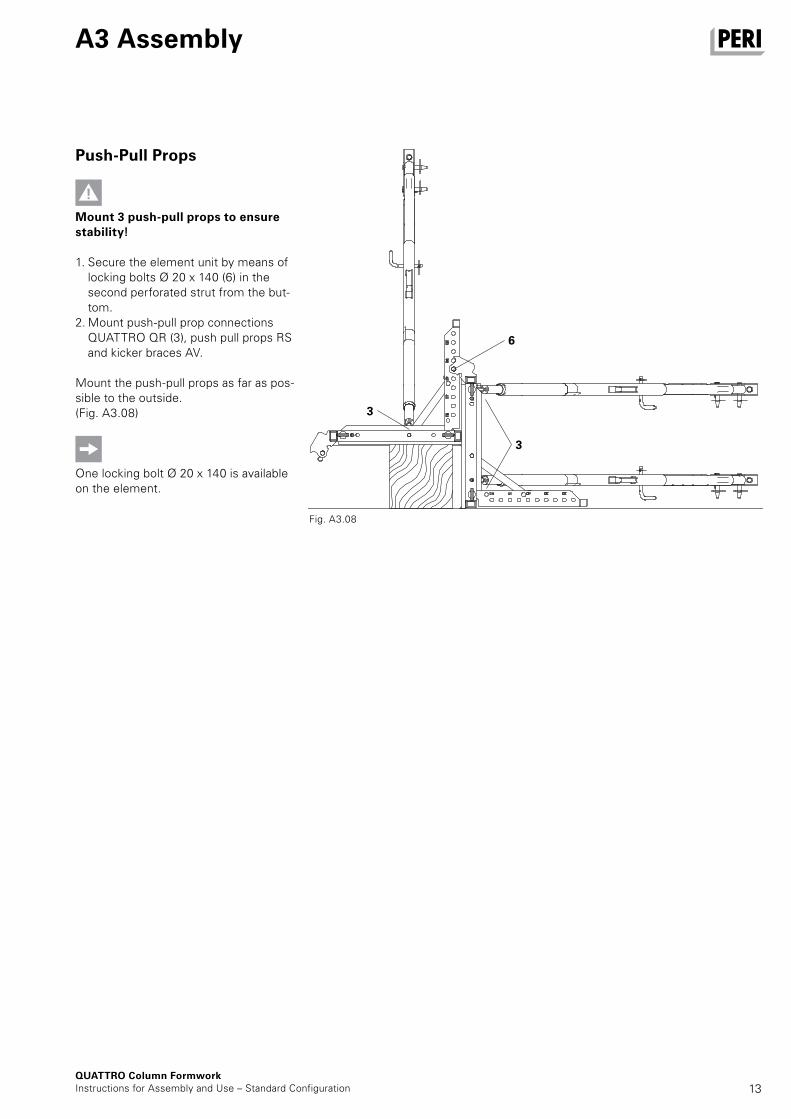
Push-Pull Props
Mount 3 push-pull props to ensure stability!
1. Secure the element unit by means of locking bolts Ø 20 x 140 (6) in the second perforated strut from the but-tom.
2. Mount push-pull prop connections QUATTRO QR (3), push pull props RS and kicker braces AV.
Mount the push-pull props as far as pos-sible to the outside. (Fig. A3.08)
One locking bolt Ø 20 x 140 is available on the element.
QUATTRO Column FormworkInstructions for Assembly and Use – Standard Configuration
6
3
3
Fig. A3.08

14
A3 Assembly
Concreting Platform
Assembly on the horizontally-positioned formwork half.
1. Remove eye bolt M20 x 110 from the QUATTRO QES Column Element and attach to one of the lower cross struts to ensure that it is not lost.
2. Remove the cam nuts DW 15 (14) from the crane eyes on the concreting platform (13) and position the plat-form by hand on the element group.
3. Push the crane eye of the concreting platform through the drilled hole (b) of the panel border and undo cam nut DW 15, SW 27. In so doing, slightly raise the concreting platform.
4. Proceed in the same way for drilled hole (c).
5. Align telescopic girder to drilled hole (d) and mount the third crane eye of the concreting platform.(Fig. A3.09)
6. Insert Platform Guardrail (12), Guard-rail 134, 2 x, Guardrail 52, 1 x. (Fig. A3.10)
If the drilled holes do not match, then turn the concreting platform by 180°.
To access the platform, slide the re-spective end guardrail upwards out of the platform and reinsert it into the designated lugs of the concret-ing platform immediately after en-tering.
Parts List for Access Ladders
QUATTRO Column FormworkInstructions for Assembly and Use – Standard Configuration
Item no.With access ladder Description 2.70 – 3.60 m 3.90 – 4.20 m
037400 Concreting Platform, Complete 1 1
051410 Ladder 180/6 2 2
103724 End Ladder 180/2 1 1
051450 Ladder Safety Cage 150 1 1
104132 Ladder Safety Cage 75 0 1
051460 Ladder Base 1 1
103718 Ladder Hook 2 2
127260 QUATTRO Ladder Connector-2 2 2
Fig. A3.09
Fig. A3.10
12
12
d c
b
14 13

15
A3 Assembly
Access Ladders
Assembly on the horizontally-positioned formwork half.
1. Position QUATTRO Ladder Connec-tions-2 (21) on the frame.
2. Insert bolts in the outermost drilled hole and secure with clamp. (Fig. A3.11)
3. Pre-assembling the ladder: – attach Ladder 180/6 (23) to Access Ladder 180/2 (22), SW 19.
– fix ladder base to Ladder 180/6.4. Adjust distance of the ladder to the
platform access point and secure with the eye bolt.
5. Fix Ladders 180/6 and 180/2 with clamping plates (28) to the QUATTRO Ladder Connections-2 (21), SW 19. (Fig. A3.12)
6. Attach Ladder Safety Cage 150 (27) using clamping plates to Access Ladder 180/2 and Ladder 180/6 using an overlapping ladder joint, SW 19. (Fig. A3.13)
Assembly at great heights1. Insert bolts in the outermost drilled
hole and secure with clamp.2. Attach Ladder 180/6 (23) to Access
Ladder 180/2 (22), SW 19.3. Depending on the height, attach addi-
tional Ladders 180/6. 4. Mount ladder hooks and ladder base
to the bottom-most ladder.5. Fix Ladders 180/6 and 180/2 with
clamping plates (28) to the ladder connections (21), SW 19.
6. Attach Ladder Safety Cage 150 and Ladder Safety Cage 75 by means of clamping plates, SW 19.
7. Attach bottom-most ladder to the vertically-positioned element.
Secure ladder safety cage above and below the ladder joint.
QUATTRO Column FormworkInstructions for Assembly and Use – Standard Configuration
Fig. A3.11
Fig. A3.13
Fig. A3.12
22
23
21
21
28
21
27

16
A4 Shuttering
Placing the Formwork
Check stability.
Always install the element unit with the concreting platform first.Bottom-extended / extended elements can only be installed as an element unit.Locating boards (30) facilitate formwork adjustment.
Formwork half with concreting platform
1. Attach 3-sling lifting gear to the crane eyes of the concreting platform, align formwork and then transport to the place of use. (Fig. A4.01)
2. Position formwork at right angles in the area of operations.
3. Secure with push-pull props and kicker braces, e.g. using PERI Anchor Bolt 14/20 x 130 or equivalent.
4. Check stability and align.5. Detach lifting gear.
(Fig. A4.02)
The first formwork half is now in position.
Fig. A4.02
QUATTRO Column FormworkInstruction for Assembly and Use - Standard Configuaration
Fig. A4.01
30

17
A4 Shuttering
Closing the Formwork
1. Assemble second unit and attach to the previously erected formwork using bolts Ø 20 x 140 and cotter pins 4/1 (1.5). Take into account the cross-section!
2. Mark out QUATTRO QR Frame Spanner (2) using the provided bolts Ø 20 x 140 (1.5). – Position of the Frame Spanner = size of column - 5 cm.
– Example: column = 35 cm, Frame Spanner = 30 cm. (Fig. A4.03)
3. Swing out QUATTRO QR Frame Spanner over the fastening straps on the adjacent element and tighten by means of the wingnuts (2.1). (Fig. A4.04)
The right angle adjusts itself automati-cally through the tensioning.
(Fig. A4.04 is shown here without the concreting platform).
The stamped measurements in the perforated waler indicate the column cross-section. (Fig. A4.03a)
QUATTRO Column FormworkInstructions for assembly and Use - Standard Configuration
1.5
2.1
2
Fig. A4.04
Fig. A4.03a
Fig. A4.03.
1.5
1.52

18
A5 Striking, Moving
Striking1. Loosen QUATTRO QA Frame
Spanner (2), remove locking pins Ø 20 x 140 (6), fold up element with the QUATTRO QA Frame Spanner and stabilise the opened position by means of the locking pins Ø 20 x 140 (6) .(Fig. A5.01)
2. Continue to open the unit until the second element is released from the concrete.
3. Stabilise the unit in the opened position using the locking pins Ø 20 x 140 (6).
4. Secure the complete formwork to the crane.
5. Release push-pull props RS and remove the complete unit from the concrete.
The push-pull props RS remain attached and the moving process takes place us-ing one crane lift.
Moving by Crane1. Attach lifting gear to the 3 crane eyes
on the concreting platform (13).2. Remove base plates of the push-pull
props RS and kickers AV from the ground.
3. Position formwork for cleaning and secure.(Fig. A5.02)
QUATTRO Column FormworkInstructions for Assembly and Use – Standard Configuration
Fig. A5.01
2
6
13
Fig. A5.02

19
A5 Striking, Moving
Formwork up to a max. height of 3.50 m may be moved by means of the transportation wheels.
Moving with Transportation Wheel1. Mount four transportation wheels
QUATTRO (7) on the closed form-work. The tube supports of the eccentric plate (7.1) are pointing upwards.(Fig. A5.03 + A5.03a)
2. Loosen the push-pull props and open formwork until the second unit is released from the concrete. Secure with bolt Ø 20 x 140. (Fig. A5.04)
3. Release the base plate fixings and press the eccentric plate downwards. – Important: pay attention to the order!
Wheel 1 - 4. (Fig. A5.04)
– The formwork is raised and the tube supports are in a horizontal position.
– Use a scaffold tube or tie rod. (Fig. A5.05)
4. Retract formwork, move, re-position formwork at next place of use and then close.
5. Press eccentric plate (7.1) upwards. The formwork is lowered and the tube supports are pointing upwards.(Fig. A5.06)
6. Fix base plates.
Wheel 2
Wheel 1
Rad 3Rad 4
ø 4
8,3
x 3
,2
QUATTRO Column FormworkInstructions for Assembly and Use – Standard Configuration
Fig. A5.03a
7.1
7
Fig. A5.03
Fig. A5.04
7.1
Fig. A5.05
Fig. A5.06

20
A6 Adjusting the Column Cross-Section
The cross-section can be adjusted if the formwork has been extended at the top and bottom, and with concreting platform. The locking pins Ø 20 x 140 (6) must always be inserted between the units (1)+(2) and (3)+(4).
Moving with AAttach unit (1) to the crane.Units (2-4) remain in position.
Moving with BAttach unit (1+2) to the crane.Units (3+4) remain in position.
Moving with CAttach unit (4) to the crane.Units (2-3) remain in position.
1. Release bolts Ø 20 x 140 (1.5) between the elements.
2. Position Frame Spanner according to the new cross-section.
3. Set out by means of bolts Ø 20 x 140 (1.5). (Fig. A6.01 + A6.01a)
4. Push elements QUATTRO QA (2) until new cross-section has been reached. (Fig. A6.01b)
Position of the Frame Spanner QUATTRO QA = size of column – 5 cm. Example: column = 35 cm,frame spanner = 30 cm.
Fig. A6.01b
Fig. A6.01
Fig. A6.01a
QUATTRO Column FormworkInstructions for Assembly and Use – Standard Configuration
B
C
A
3
4
1
2
1.5
1.5
30
2
6
6

21QUATTRO Column FormworkInstructions for Assembly and Use – Standard Configuration

QUATTRO Column Formwork
22
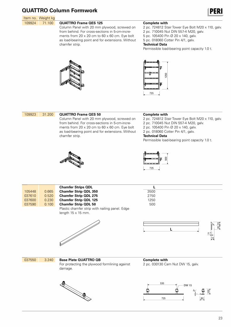
Item no. Weight kg
109925 152.000 QUATTRO Frame QES 275Column Panel with 20 mm plywood, screwed on from behind. For cross-sections in 5-cm-incre-ments from 20 x 20 cm to 60 x 60 cm. Eye bolt as load-bearing point and for extensions. Without chamfer strip.
Complete with2 pc. 724812 Stair Tower Eye Bolt M20 x 110, galv.2 pc. 710045 Nut DIN 557-4 M20, galv.9 pc. 105400 Pin Ø 20 x 140, galv.9 pc. 018060 Cotter Pin 4/1, galv.1 pc. 037550 Base Plate QUATTRO QBTechnical DataPermissible load-bearing point capacity 1.0 t.
2750
725
109926 199.000 QUATTRO Frame QES 350Column Panel with 20 mm plywood, screwed on from behind. For cross-sections in 5-cm-incre-ments from 20 x 20 cm to 60 x 60 cm. Eye bolt as load-bearing point and for extensions. Without chamfer strip.
Complete with2 pc. 724812 Stair Tower Eye Bolt M20 x 110, galv.2 pc. 710045 Nut DIN 557-4 M20, galv.13 pc. 105400 Pin Ø 20 x 140, galv.13 pc. 018060 Cotter Pin 4/1, galv.1 pc. 037550 Base Plate QUATTRO QBTechnical DataPermissible load-bearing point capacity 1.0 t.
3500
693
835
725
725
QUATTRO Column Formwork
23
Item no. Weight kg
037550 3.240 Base Plate QUATTRO QBFor protecting the plywood formlining against damage.
Complete with2 pc. 030130 Cam Nut DW 15, galv.
725
530
80
100
DW 15
3°105448037610037600037590
0.665 0.520 0.230 0.100
Chamfer Strips QDLChamfer Strip QDL 350Chamfer Strip QDL 275Chamfer Strip QDL 125Chamfer Strip QDL 50Plastic chamfer strip with nailing panel. Edge length 15 x 15 mm.
L 3500 2750 1250 500
L 2015
2,7
15
109923 31.200 QUATTRO Frame QES 50Column Panel with 20 mm plywood, screwed on from behind. For cross-sections in 5-cm-incre-ments from 20 x 20 cm to 60 x 60 cm. Eye bolt as load-bearing point and for extensions. Without chamfer strip.
Complete with2 pc. 724812 Stair Tower Eye Bolt M20 x 110, galv.2 pc. 710045 Nut DIN 557-4 M20, galv.2 pc. 105400 Pin Ø 20 x 140, galv.2 pc. 018060 Cotter Pin 4/1, galv.Technical DataPermissible load-bearing point capacity 1.0 t.
500
725
109924 71.100 QUATTRO Frame QES 125Column Panel with 20 mm plywood, screwed on from behind. For cross-sections in 5-cm-incre-ments from 20 x 20 cm to 60 x 60 cm. Eye bolt as load-bearing point and for extensions. Without chamfer strip.
Complete with2 pc. 724812 Stair Tower Eye Bolt M20 x 110, galv.2 pc. 710045 Nut DIN 557-4 M20, galv.5 pc. 105400 Pin Ø 20 x 140, galv.5 pc. 018060 Cotter Pin 4/1, galv.Technical DataPermissible load-bearing point capacity 1.0 t.
1250
725

QUATTRO Column Formwork
24
Item no. Weight kg
105400 0.330 Pin Ø 20 x 140, galv.For different connections.
89140
Ø8
Ø20
018060 0.014AccessoriesCotter Pin 4/1, galv.
724500 0.098 Bolt Ø 20 x 42, QUATTRO, galv.For different connections.
42
20Ø5
018060 0.014AccessoriesCotter Pin 4/1, galv.
037530 1.130 Brace Connector QUATTRO QRFor connecting push-pull props and kicker braces to QUATTRO and LICO Panels.
Complete with1 pc. 027170 Pin Ø 16 x 42, galv.1 pc. 018060 Cotter Pin 4/1, galv.
24
155
93
037540 2.370 Frame Spanner QUATTRO QAFor bracing QUATTRO Column Panels. Only required at a column corner.
NoteRequired no. of pieces: h = 3.50 m 6 pieces, h = 2.75 m 4 pieces h = 1.25 m 2 pieces, h = 0.50 m 1 piece
5745
89
249
195
Ø21DW 15
105400 018060
0.330 0.014
AccessoriesPin Ø 20 x 140, galv.Cotter Pin 4/1, galv.

QUATTRO Column Formwork
25
Item no. Weight kg
127260 9.240 QUATTRO Ladder Connector-2For connecting ladders to QUATTRO Column Panels.
Complete with2 pc. 710266 Bolt ISO 4017 M12 x 25-8.8, galv.2 pc. 701763 Clamping Plate Fl 25 x 10 x 90
50 160
410
1100
454 30 265
103391 4.890 Ladder Connector QUATTRO
750
453
260
160
105791 16.900 Transportation Wheel QUATTROFor moving completely assembled QUATTRO Column Formwork. Always use 4 pieces per column.
Technical DataPermissible load-bearing capacity 500 kg.
642
464 135
018060 0.014 Cotter Pin 4/1, galv.
Ø4
QUATTRO Column Formwork
26
Item no. Weight kg
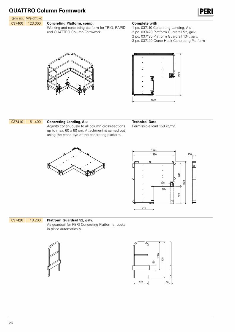
037420 10.200 Platform Guardrail 52, galv.As guardrail for PERI Concreting Platforms. Locks in place automatically.
1005
1305
525
150
50
037410 51.400 Concreting Landing, AluAdjusts continuously to all column cross-sections up to max. 60 x 60 cm. Attachment is carried out using the crane eye of the concreting platform.
Technical DataPermissible load 150 kg/m2.
14201524
710
840
620
1524Ø21
Ø14
130
037400 123.000 Concreting Platform, compl.Working and concreting platform for TRIO, RAPID and QUATTRO Column Formwork.
Complete with1 pc. 037410 Concreting Landing, Alu2 pc. 037420 Platform Guardrail 52, galv.2 pc. 037430 Platform Guardrail 134, galv.3 pc. 037440 Crane Hook Concreting Platform
1521
1521

QUATTRO Column Formwork
27
Item no. Weight kg
051460 2.180 Ladder Base, galv.As bottom ladder connection and for securing ladders against sliding on the scaffold decks.
405
210
50
037440 5.640 Crane Hook Concreting PlatformFor assembling the concreting landing to the TRIO, RAPID and QUATTRO column frames.
NoteFollow Instructions for Assembly and Use!Technical DataPermissible load-bearing capacity 1.0 t.
252
511
137
DW 1570
120
115352 15.300 Platform Front Guardrail 86/86As guardrail for PERI Concreting Platforms towards the column. Mounted with Screw-on Coupler.
NoteWrench size SW 19.
824
1150
037430 17.100 Platform Guardrail 134, galv.As guardrail for PERI Concreting Platforms. Locks in place automatically.
1340 50
150
1005
1305

QUATTRO Column Formwork
28
Item no. Weight kg
103718 0.684 Ladder Hook, galv.For adjusting the bottom ladder. Always use in pairs.
Complete with2 pc. 710266 Bolt ISO 4017 M12 x 25-8.8, galv.2 pc. 710381 Nut ISO 7042 M12-8, galv.
330 SW 19
104132051450
15.600 25.200
Lader Safety Cages, galv.Ladder Safety Cage 75, galv.Ladder Safety Cage 150, galv.Ladder safety cage for PERI Access Ladders.
Complete with4 pc. 710266 Bolt ISO 4017 M12 x 25-8.8, galv.4 pc. 701763 Clamping Plate Fl 25 x 10 x 90
750
/150
0
710
704
SW 19
103724 10.400 End Ladder 180/2, galv.As access for PERI Formwork Systems.
Complete with4 pc. 710224 Bolt ISO 4017 M12 x 40-8.8, galv.4 pc. 710381 Nut ISO 7042 M12-8, galv.
298 12001885
450
051410 11.700 Ladder 180/6, galv.As access for PERI Formwork Systems.
Complete with4 pc. 710224 Bolt ISO 4017 M12 x 40-8.8, galv.4 pc. 710381 Nut ISO 7042 M12-8, galv.
14905 x 298 = 831960
450
SW 19

QUATTRO Column Formwork
29
Item no. Weight kg
117468 23.000 Push-Pull Prop RS 450, galv.Extension length l = 2.80 – 4.50 m. For aligning PERI Formwork Systems and precast concrete elements.
NotePermissible load see PERI Design Tables.
2670
73Ø
2800min max 4500
9
Ø48,3
Ø21Ø17
117467 15.500 Push-Pull Prop RS 300, galv.Extension length l = 1.90 – 3.00 m. For aligning PERI Formwork Systems and precast concrete elements.
NotePermissible load see PERI Design Tables.
1773
64,5
Ø
1900min max 3000
Ø48,3
Ø21 Ø179
118238 12.100 Push-Pull Prop RS 260, galv.Extension length l = 2.30 – 2.60 m. For aligning PERI Formwork Systems and precast concrete elements.
NotePermissible load see PERI Design Tables.
60,6
Ø2178
min 2300 max 2600
9
Ø21
Ø48,3
Ø17
117466 10.600 Push-Pull Prop RS 210, galv.Extension length l = 1.30 – 2.10 m. For aligning PERI Formwork Systems and precast concrete elements.
NotePermissible load see PERI Design Tables.
1178
60,6
Ø
1300min max 2100
9
Ø17Ø21
Ø48,3

QUATTRO Column Formwork
30
Item no. Weight kg
103800 271.000 Push-Pull Prop RS 1400, galv.Extension length l = 6.40 – 14.00 m. For aligning PERI Formwork Systems.
NotePermissible load see PERI Design Tables. Chain can be operated from bottom.
min 6400 max 14000
6460
17 x 200 = 3400 17 x 200 = 3400
10
Ø48,3 Ø48,3
Ø21 Ø21Ø17
400 400
028990 115.000 Push-Pull Prop RS 1000, galv.Extension length l = 6.40 – 10.00 m. For aligning PERI Formwork Systems.
NotePermissible load see PERI Design Tables.
min 6325 max 10000
10
102
Ø
Ø48,3 Ø17
117469 39.900 Push-Pull Prop RS 650, galv.Extension length l = 4.30 – 6.50 m. For aligning PERI Formwork Systems and precast concrete elements.
NotePermissible load see PERI Design Tables.
88,9
Ø4140
4300min max 6500
Ø17Ø21
Ø48,3

QUATTRO Column Formwork
31
Item no. Weight kg
028010 17.900 Push-Pull Prop RSS IExtension length l = 2.05 – 2.94 m. For aligning PERI Formwork Systems.
NotePermissible load see PERI Design Tables.
2050min max 2940
1915Ø16,5
10
Ø32
70Ø
113397 1.600AccessoriesSpindle Handle RSS / AV
117343 3.250 Base Plate-2 for RS 210 - 1400, galv.For assembly of Push-Pull Props RS 210, 260, 300, 450, 650, 1000 and 1400.
Complete with2 pc. 105400 Pin Ø 20 x 140, galv.2 pc. 018060 Cotter Pin 4/1, galv.
261
106
5264
Ø21
124777 0.210AccessoriesAnchor Bolt PERI 14/20 x 130
102018 4.880 Base Plate-2 for RS 1000/1400, galv.For assembly of Push-Pull Props RS 210, 260, 300, 450, 650, 1000, 1400 and Heavy Duty Spindles.
Complete with2 pc. 105400 Pin Ø 20 x 140, galv.2 pc. 018060 Cotter Pin 4/1, galv.
290 95
Ø21 108
126666 3.070 Base Plate-3 for RS 210 - 1400For assembly of Push-Pull Props RS 210, 260, 300, 450, 650, 1000 and 1400.
Complete with2 pc. 105400 Pin Ø 20 x 140, galv.2 pc. 018060 Cotter Pin 4/1, galv.1 pc. 113063 Bolt ISO 4014 M12 x 80-8.8, galv.1 pc. 113064 Hex Nut ISO7042-M12-8-G, galv.
264
64
52
105
Ø21
124777 0.210AccessoriesAnchor Bolt PERI 14/20 x 130

QUATTRO Column Formwork
32
Item no. Weight kg
106000 1.820 Base Plate-2 for RSS, galv.For assembly of Push-Pull Props RSS.
Complete with1 pc. 027170 Pin Ø 16 x 42, galv.1 pc. 018060 Cotter Pin 4/1, galv.
150
Ø21
Ø11
100 1285
124777 0.210AccessoriesAnchor Bolt PERI 14/20 x 130
028030 38.400 Push-Pull Prop RSS IIIExtension length l = 4.60 – 6.00 m. For aligning PERI Formwork Systems.
NotePermissible load see PERI Design Tables.
min 4600 max 6000
4399Ø16,5 Ø16,5
Ø48,3
915
82,5
Ø
028020 22.000 Push-Pull Prop RSS IIExtension length l = 2.91 – 3.80 m. For aligning PERI Formwork Systems.
NotePermissible load see PERI Design Tables.
min 2910 max 3800
Ø16,5Ø16,52775
Ø32
10
70Ø
15
113397 1.600AccessoriesSpindle Handle RSS / AV
113397 1.600 Spindle Handle RSS / AVSpindle handle for screwing on Push-Pull-Props RSS I, RSS II and Kickers AV 210 and AV RSS III.
Complete with2 pc. 722342 Screw ISO 4017 M8 x 25-8.8, galv.2 pc. 711071 Nut ISO 7042 M8-8, galv.
196
179
130

QUATTRO Column Formwork
33
Item no. Weight kg
108135 12.900 Kicker AV 210Extension length l = 1.28 – 2.10 m. For aligning PERI Formwork Systems.
Complete with1 pc. 027170 Pin Ø 16 x 42, galv.1 pc. 018060 Cotter Pin 4/1, galv.NotePermissible load see PERI Design Tables.
min 1280 max 2100
Ø16x42 Ø16,5
Ø36
70Ø
1171
1010
113397 1.600AccessoriesSpindle Handle RSS / AV
028110 4.850 Kicker AV 140Extension length l = 1.08 – 1.40 m. For aligning PERI Formwork Systems.
Complete with1 pc. 027170 Pin Ø 16 x 42, galv.1 pc. 018060 Cotter Pin 4/1, galv.NotePermissible load see PERI Design Tables.
min 1080 max 1400
38Ø Ø16x42Ø16,5
Ø30
980
10 10
057087057088
3.510 4.200
Kicker AVKicker AV 82Kicker AV 111For aligning PERI Formwork Systems.
min. L max. L 500 820 790 1110 Complete with1 pc. 027170 Pin Ø 16 x 42, galv.1 pc. 018060 Cotter Pin 4/1, galv.NotePermissible load see PERI Design Tables.
min 790 max 1110min 500 max 820
38Ø
390
10 10
Ø16,5
Ø30
Ø16x42
690

QUATTRO Column Formwork
34
Item no. Weight kg
124777 0.210 Anchor Bolt PERI 14/20 x 130For temporary fixation to reinforced concrete structures.
NoteSee PERI Data Sheet! Drilling Ø 14 mm.
130
SW 24Ø14
028080 2.970 Connector Kicker/Push-Pull Prop, galv.For connecting push-pull props and kicker braces to Main Beam HDT.
Complete with1 pc. 027170 Pin Ø 16 x 42, galv.1 pc. 018060 Cotter Pin 4/1, galv.
200 100 1285
Ø25
028120 17.000 Kicker AV RSS IIIExtension length l = 2.03 – 2.92 m. For aligning PERI Formwork Systems.
Complete with1 pc. 027170 Pin Ø 16 x 42, galv.1 pc. 018060 Cotter Pin 4/1, galv.NotePermissible load see PERI Design Tables.
min 2030 max 2920
1915Ø16x42 Ø16,5
Ø32
10 10
70Ø
113397 1.600AccessoriesSpindle Handle RSS / AV


PERI GmbHFormwork Scaffolding EngineeringRudolf-Diesel-Strasse 1989264 WeissenhornGermanyTel. +49 (0)7309.950-0Fax +49 (0)[email protected]
DE
en 0
8 | 2
018
1m
a 7
907
13 ©
PE
RI G
mbH
The optimal System for every Project and every Requirement
System-Independent Accessories
Column FormworkWall Formwork Slab Formwork
Climbing Systems Bridge Formwork Tunnel Formwork Shoring Systems
Construction Scaffold Industrial ScaffoldFacade Scaffold Access
Protection Scaffold Safety Systems Services