QUARTZ BATH INSTALLA TION GUIDE
19
QUARTZ ™ BATH INSTALLATION GUIDE
Transcript of QUARTZ BATH INSTALLA TION GUIDE

QUARTZ™ BATHINSTALLATION
GUIDE

Quartz™ Bath Installation Guide 02
COMPONENTS (HP/COMBI)
Mains fed and separately pumped water systems only

Quartz™ Bath Installation Guide 03
COMPONENTS (GRAVITY PUMPED)
Gravity stored water systems only

Quartz™ Bath Installation Guide 04
IMPORTANT INFORMATIONSafety informationThis appliance can be used by children aged from 3 years and above and persons with reduced physical, sensory or mental capabilities or lack of experience and knowledge if they have been given supervision or instruction concerning use of the appliance in a safe way and understand the hazards involved.
Children shall not play with the appliance.
Cleaning and user maintenance shall not be made by children without supervision.
This product must be installed by a competent person in accordance with all relevant current local and national Water Supply Regulations.
ALL PRODUCTS REQUIRING AN ELECTRICAL CONNECTION MUST BE INSTALLED BY A QUALIFIED PERSON FOLLOWING THE LATEST REVISION OF THE ELECTRICAL WIRING REGULATIONS, BOTH NATIONAL AND LOCAL AND CERTIFIED TO CURRENT BUILDING REGULATIONS.
This system should be installed so that other taps or appliances operated elsewhere within the premises do not significantly affect the flow.
The Quartz Smart Valve™ must not be used with a hot water supply temperature of over 65ºC. If the maximum hot water temperature is likely to rise above 65ºC then a Thermostatic Blending Valve must be used.
The Quartz Smart Valve™ is supplied factory pre-set at maximum temperature of 45ºC. The maximum temperature is fully adjustable to suit site conditions. If adjusted, we recommend the outlet temperature is set to a MAXIMUM of 46ºC.
The Quartz Smart Valve™ must be installed in an accessible location for servicing and maintenance.
The Quartz Smart Valve™ must not be installed in situations where either the ambient temperature is likely to exceed 40ºC or where freezing may occur.
The bath controller must not be installed in situations where the ambient temperature is likely to fall below 5ºC or rise above 40ºC.
We do not recommend the use of a bath controller in steam therapy facilities.
This appliance must be earthed.
Cables must be protected by a suitably sized conduit or trunking to avoid risk of damage and to allow removal for service and maintenance purposes. Failure to install this way may invalidate the warranty.
Ensure that the conduit is run to avoid the bath controller fixing holes.
Surface mounted cables must also be protected by a suitable approved conduit, even in a loft, where there may be a risk of damage from vermin.
The power lead must only be replaced by the manufacturer or his accredited agent.
The bath controller is supplied from a safety low voltage source.
This product is suitable for domestic use only.
Aqualisa products are supplied complete with a 1 year guarantee that can be upgraded by registering the product with Aqualisa.
See www.aqualisa.co.uk/guarantee for details.
Installation of the pumped Quartz Smart Valve™ (for gravity stored systems)The pumped Quartz Smart Valve™ shower system is designed to operate up to a maximum static pressure of 100kPa ((1 bar)(10 metres head)(14.5psi)). Under no circumstances must the pumped Quartz Smart Valve™ be connected directly to the water main or in line with another booster pump.
The minimum actual capacity of the cold water storage cistern should be not less than 225 litres (50 gallons). The capacity of the hot water cylinder must be capable of meeting anticipated demand.

Quartz™ Bath Installation Guide 05
Installation of the standard (unpumped) Quartz Smart Valve™ (for balanced high pressure and unvented systems, combination boiler systems and separately pumped gravity systems)Pressures: The standard (unpumped) Quartz Smart Valve™ is designed to operate up to a maximum static pressure of 700kPa ((7 bar)(100psi)). Where pressures are likely to exceed 700kPa ((7 bar)(100psi)), a pressure reducing valve must be fitted to the incoming mains supply. A setting of 400kPa ((4 bar)(60psi)) is recommended. It should be noted that daytime pressures approaching 600kPa ((6 bar)(80psi)) can rise above the stated maximum overnight.
Special notes for combination boiler systemsThe appliance must have a minimum domestic hot water rating of 24kW and be of the type fitted with a fully modulating gas valve.
If in any doubt, please contact the appliance manufacturer before installation commences.
PLEASE NOTE: DUE TO PERFORMANCE CHARACTERISTICS OF COMBINATION BOILERS, SEASONAL INLET TEMPERATURE CHANGE WILL AFFECT THE QUARTZ SMART VALVE™ OUTLET FLOW RATE RESULTING IN VARYING SHOWER FLOW RATE AND FLOW CONTROL RANGE. INLET TEMPERATURE CHANGE MAY ALSO CAUSE THE TEMPERATURE DISPLAY TO FLASH; THIS IS NOT NECESSARILY CHANGING THE OUTLET TEMPERATURE.
Special notes for separately pumped gravity systems and universal/negative head pumps (for divert systems)We recommend a MINIMUM pump rating of 1.5 bar. For optimum performance a 2.5 bar pump should be used for all separately pumped installations.
A twin ended pump is required for use with single outlet products.
A universal/negative head type twin ended pump (works on both positive and negative head conditions) MUST be used with divert products.
The minimum actual capacity of the cold water storage cistern should be not less than 225 litres (80 gallons). The capacity of the hot water cylinder must be capable of meeting the anticipated demand.
THIS PRODUCT IS NOT SUITABLE FOR USE WITH A SINGLE ENDED PUMP.
ConnectionsThis product incorporates 15mm ‘push-fit’ type connections. Tube should be cut using a rotary type cutter and lubricated using a silicone grease, petroleum jelly, or similar, prior to insertion into the fitting. 15mm pipework must be used to connect the product.
If plastic pipe is used, the tube insert must not increase the tube diameter or extend the cut-off length by more than 2mm.
THESE FITTINGS ARE NOT SUITABLE FOR STAINLESS STEEL TUBE. COMPRESSION FITTINGS MUST NOT BE USED.
Pipe sizing PLEASE NOTE: Check pipe size requirements for connections to outlets and accessories. Long pipe runs, on both inlet and outlet, will reduce the flow rate at the shower head, 22mm pipe work should be used on inlets and reduce down to 15mm as close to the valve as possible to reduce pressure losses and help maintain flow rate. If using 15mm pipe, copper pipe is preferred, to optimise performance minimise the number of elbows used. If long pipe runs are unavoidable on the outlet, use copper pipe rather than plastic, particularly if a diverter is used, and minimise the number of elbows as the pipe inserts are very restrictive.
FlushingSome modern fluxes can be very corrosive and, if left in contact, will attack the working parts of this unit. All soldering must be completed and the pipe work thoroughly flushed out in accordance with current local and national Water Supply Regulations prior to connection of the product.
Declaration of conformityAqualisa Products Limited declares that the Quartz Smart Valve™ and bath controller, in conjunction with the wired remote, complies with the essential requirements and other relevant provisions of the Low Voltage Directive (2014/35/EU) and the EMC Directive (2014/30/EU).
After installationFamiliarise the end user with the operation of this product and hand them this guide. Complete and post the guarantee card or register online at www.aqualisa.co.uk

Quartz™ Bath Installation Guide 06
QUARTZ™ BATH INSTALLATIONThis product must be installed by a competent person in accordance with the relevant Water Supply Regulations.Prior to installation, ensure all additional guides supplied with this product are read and understood.In addition to the guide below, it is essential that the important information (overleaf) is read and understood and that you have all the necessary components before commencing installation.The Quartz™ bath system is supplied with universal fixings intended to secure the Quartz Smart Valve™ to a suitable surface.
•
!
Although the Quartz Smart Valve™ complies with all relevant EMC standards, if incorrectly sited, it may interfere with digital TV reception. Please follow the recommendations below to minimise this effect.
If TV interference is an issue a service kit is available (part no: 652102).
See recommended layouts below.
Images of Quartz Smart Valve™ for illustration only, refer to instruction 1 for orientation.
Valve colour may vary – the Original Quartz™ valve being black, and the Quartz Smart Valve™ being orange.
• Route cables separately, and as far apart from each other as possible.
• Aerial to point away from the Quartz Smart Valve™.
• Ensure the distance between the Quartz Smart Valve™ and the aerial is as large as possible.
DIGITAL TV INTERFERENCE
AERIAL
LARGEST POSSIBLE DISTANCE
DATA CABLE
POWER CABLE
CABLE TO TV
HIGH PROBABILITY OF INTERFERENCE,
BOTH RADIATED AND CONDUCTED
POWER CABLE CABLE
TO TV
DATA CABLE
AERIAL
SHORT DISTANCE
LAYOUT WHICH COULD CAUSE PROBLEMSLOWEST PROBABILITY OF INTERFERENCE
1
To ensure safe operation and installation of this product, the Quartz Smart Valve™ MUST be installed in one of the orientations shown.
300 mm
210 mm
70 mm
300 mm
210 mm
210 mm
450 mm
450 mm
70 mm

Quartz™ Bath Installation Guide 07
2Isolation valves are supplied with the Quartz Smart Valve™ and must be fitted on both inlets and the blended water outlet. All pipe work should be run in 15mm pipe. All pipe work should be supported. For gravity fed installations, 22mm pipe work should
be run as close to the Quartz Smart Valve™ as possible before reducing down to 15mm.
To ensure optimum performance we recommend using copper pipe with a minimum number of elbows.
•
!
The inlet supply centres are 48mm.Please note arrow on isolation valve to indicate direction of flow.DO NOT use compression fittings on the inlet and outlet spigots this will affect the warranty if fitted.
•
!
3Choose the position for your Quartz Smart Valve™ as close to the bath controller as possible. The Quartz Smart Valve™ may be sited in the roof space above the proposed bath site, in the airing cupboard or behind a screwed bath panel if more convenient. For information regarding protecting the Quartz Smart Valve™ from cold/frost, contact Aqualisa Customer Services or refer to the Aqualisa website. Insulation material must not be placed under or on top of the Quartz Smart Valve™, the location should be where freezing cannot occur.
Please refer to the system layout diagrams.
The Quartz Smart Valve™ MUST be sited in a position that is safely accessible for servicing and commissioning purposes. When fitted in a loft space, the route to and the area around the Quartz Smart Valve™ must be boarded to ensure a safe working environment.
The optimum position for the Quartz Smart Valve™ is in the roof space above the controller site to take full advantage of the ease and speed of installation.
The distance between the Quartz Smart Valve™ and the controller must be within the range of the 10m data cable supplied.
4Place the Quartz Smart Valve™ on a solid mounting surface, and place the fixing feet into suitable positions. Mark, then drill and
prepare suitable fixings before securing the Quartz Smart Valve™ to the mounting surface using the screws provided, (if suitable).

Quartz™ Bath Installation Guide 08
5Flush through both hot and cold supply pipes.
REFER TO SAFETY INFORMATION SECTIONThe maximum hot water inlet temperature must be no more than 65˚C.
•
!
6Attach the supply pipes to the Quartz Smart Valve™, ensuring that the cold and hot feeds are fitted into the appropriately marked inlets.
7Run a pipe from the mixed water outlet of the Quartz Smart Valve™ to the proposed siting for the bath fill outlet.
To ensure optimum performance we recommend using copper pipe with a minimum number of elbows.
•
!
Suitable non restrictive double check valves (not supplied) MUST be fitted to the blended outlet pipe in line with the current Water Supply Regulations.
•
!
8Place the paper template on the wall in the desired location for the bath controller and mark all fixing points and the data cable entry point. Remove the template and drill a Ø16mm hole at the appropriate position for the data cable.
Ensure the data cable is the correct way round as both ends differ in type of connection used (transparent connector to the Quartz Smart Valve™).
Data cables must be protected by suitable sheathing or conduit in the event of servicing and maintenance. Failure to install this way may invalidate the warranty.
Care should be taken to ensure the mounting holes do not pierce the data cable conduit.
•
!
If installing this Quartz™ product as a replacement product, it may be necessary to purchase a concealed retro-fit wall plate to cover the existing hole in the tiling. The cavity in the wall should be plugged using a suitable material for the wall plate to be secured to. Contact our Customer Service Department to purchase product code:
QZD.B3.RWP.14 – Quartz Smart Valve™ concealed retro-fit wall plate.
Quartz™ Bath Installation Guide 09
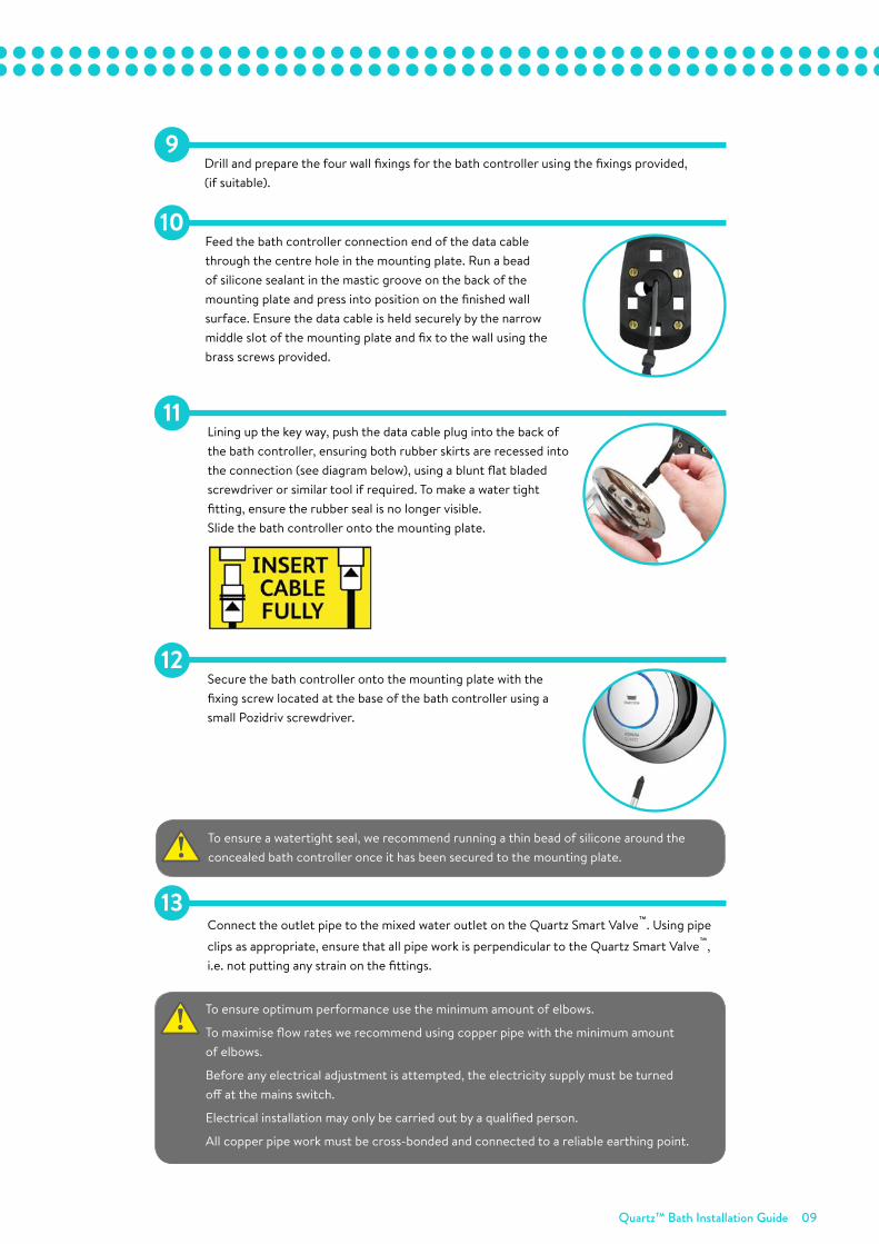
9Drill and prepare the four wall fixings for the bath controller using the fixings provided, (if suitable).
10Feed the bath controller connection end of the data cable through the centre hole in the mounting plate. Run a bead of silicone sealant in the mastic groove on the back of the mounting plate and press into position on the finished wall surface. Ensure the data cable is held securely by the narrow middle slot of the mounting plate and fix to the wall using the brass screws provided.
11Lining up the key way, push the data cable plug into the back of the bath controller, ensuring both rubber skirts are recessed into the connection (see diagram below), using a blunt flat bladed screwdriver or similar tool if required. To make a water tight fitting, ensure the rubber seal is no longer visible.Slide the bath controller onto the mounting plate.
12Secure the bath controller onto the mounting plate with the fixing screw located at the base of the bath controller using a small Pozidriv screwdriver.
•
! To ensure a watertight seal, we recommend running a thin bead of silicone around the concealed bath controller once it has been secured to the mounting plate.
13Connect the outlet pipe to the mixed water outlet on the Quartz Smart Valve™. Using pipe
clips as appropriate, ensure that all pipe work is perpendicular to the Quartz Smart Valve™, i.e. not putting any strain on the fittings.
To ensure optimum performance use the minimum amount of elbows.
To maximise flow rates we recommend using copper pipe with the minimum amount of elbows.
Before any electrical adjustment is attempted, the electricity supply must be turned off at the mains switch.
Electrical installation may only be carried out by a qualified person.
All copper pipe work must be cross-bonded and connected to a reliable earthing point.
•
!

Quartz™ Bath Installation Guide 10
14Connect the Quartz Smart Valve™ power lead to a double pole 3 amp fuse switched spur incorporated in the fixed wiring circuit, in accordance with current wiring rules (refer to safety information section). Ensure that this is located in an accessible, dry location and not in the bathroom.
THIS APPLIANCE MUST BE EARTHED We recommend protecting surface mounted cables in suitable approved conduit to avoid the risk of damage from vermin.The power lead should also be clipped in place with ‘P’ clips or similar to avoid accidents.
•
!
15Loosen the single fixing screw on the top of the Quartz Smart
Valve™ and then carefully tilt the lid up and off the location lugs, and set the lid aside.
Plug in the transparent connector of the low voltage, 10m data cable into the socket adjacent to the temperature adjuster as indicated on the label. Feed the cable out of the Quartz Smart
Valve™ ensuring it is correctly routed within the data cable channel.
A further data cable socket has been provided for use with a wired remote or diverter. This can be accessed by carefully snapping and removing the entry pillar and connecting the cable as described above. Please refer to the Wired Remote Installation Guide or Diverter Installation Guide for the relevant wiring diagrams.
•
!
16The Quartz Smart Valve™ is supplied factory set to either ‘NORMAL HP’ mode or ‘NORMAL GRAVITY’ mode depending on which product has been ordered.
BALANCED HP SYSTEMS AND SEPARATELY PUMPED GRAVITY SYSTEMS:The standard Quartz Smart Valve™ fits to balanced high pressure systems or separately pumped gravity systems. It may be set to ‘NORMAL HP’, or for water economy, ‘ECO HP’ mode.
STANDARD COMBINATION BOILER SYSTEMS:When installed on combi boiler systems, the standard Quartz Smart
Valve™ should be set to ‘COMBI’ mode for optimum performance.
GRAVITY PUMPED QUARTZ SMART VALVE™:The gravity pumped Quartz Smart Valve™ installed on gravity systems ONLY may be set to ‘NORMAL GRAVITY’, or for water economy, ‘ECO GRAVITY’ mode.
In order to fill your bath as quickly and efficiently as possible, we recommend the ‘ECO’ settings are not used.
•
!
When making any adjustment to the Quartz Smart Valve™ settings the power MUST be isolated.
•
!

Quartz™ Bath Installation Guide 11
17Reinstate the electrical supply to the Quartz Smart Valve™. Press the ‘Start/Stop’ button on the bath controller to turn the bath on.
18Run the bath at maximum temperature (factory pre set to 45ºC). If required, maximum temperature adjustment can be made with a flat bladed screwdriver using the ‘MAX TEMP ADJUSTMENT’ control as indicated. When the temperature has been set to the desired position, carefully replace the
Quartz Smart Valve™ lid and secure the fixing screw, hand tight only.
Site conditions can affect temperature settings, installer to adjust as required.
•
!
Quartz™ Bath Installation Guide 12
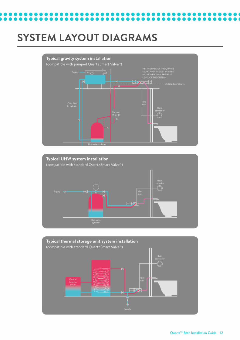
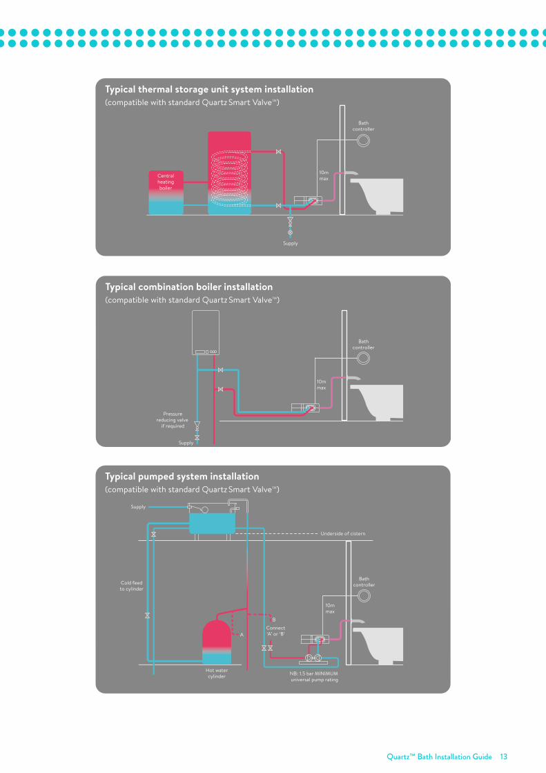
SYSTEM LAYOUT DIAGRAMS
Typical gravity system installation(compatible with pumped Quartz Smart ValveTM)
Typical combination boiler installation(compatible with standard Quartz Smart ValveTM)
Typical UHW system installation(compatible with standard Quartz Smart ValveTM)
Typical thermal storage unit system installation(compatible with standard Quartz Smart ValveTM)
Typical pumped system installation(compatible with standard Quartz Smart ValveTM)
Supply
Hot watercylinder
10mmax
Bathcontroller
10mmax
Bathcontroller
Centralheatingboiler
Supply
Supply
Pressurereducing valve
if required
10mmax
Bathcontroller
Supply
Hot water cylinder
Connect‘A’ or ‘B’
Cold feedto cylinder
B
A
NB: THE BASE OF THE QUARTZ SMART VALVETM MUST BE SITED NO HIGHER THAN THE BASE LEVEL OF THE CISTERN
10mmax
Underside of cistern
Bathcontroller
Supply
Underside of cistern
Hot watercylinder NB: 1.5 bar MINIMUM
universal pump rating
Cold feedto cylinder
Connect‘A’ or ‘B’
B
A
10mmax
Bathcontroller
Quartz™ Bath Installation Guide 13
Typical gravity system installation(compatible with pumped Quartz Smart ValveTM)
Typical combination boiler installation(compatible with standard Quartz Smart ValveTM)
Typical UHW system installation(compatible with standard Quartz Smart ValveTM)
Typical thermal storage unit system installation(compatible with standard Quartz Smart ValveTM)
Typical pumped system installation(compatible with standard Quartz Smart ValveTM)
Supply
Hot watercylinder
10mmax
Bathcontroller
10mmax
Bathcontroller
Centralheatingboiler
Supply
Supply
Pressurereducing valve
if required
10mmax
Bathcontroller
Supply
Hot water cylinder
Connect‘A’ or ‘B’
Cold feedto cylinder
B
A
NB: THE BASE OF THE QUARTZ SMART VALVETM MUST BE SITED NO HIGHER THAN THE BASE LEVEL OF THE CISTERN
10mmax
Underside of cistern
Bathcontroller
Supply
Underside of cistern
Hot watercylinder NB: 1.5 bar MINIMUM
universal pump rating
Cold feedto cylinder
Connect‘A’ or ‘B’
B
A
10mmax
Bathcontroller

Quartz™ Bath Installation Guide 14
QUARTZ™ BATH OVERFLOW FILLER
The bath overflow filler is suitable for baths up to a maximum thickness of 24mm.
•
!
Installation videos are available on our website www.aqualisa.co.uk/installation-videos or alternatively, scan the QR codes on the reverse of this guide.
Carefully unscrew and remove the overflow filler outlet from the body assembly and set aside.
1
Carefully unscrew and remove the bath waste clicker assembly from the waste body and set aside.
2
Offer the bath waste into position ensuring the rubber washer is correctly aligned between the waste assembly and the bath base.
3
Ensuring the rubber washer is correctly aligned, pass the bath waste clicker through the bath and secure to the waste body assembly.
4

Quartz™ Bath Installation Guide 15
Connect the bath waste to a suitable waste pipe.5
Offer the outlet body assembly into position at the rear of the bath ensuring the rubber washer is correctly aligned between the outlet body assembly and bath wall.
6
Ensuring the rubber washer is correctly aligned, pass the overflow filler outlet through the bath and secure to the body assembly.
7
Remove the relevant inlet blanking plug and attach the flexible hose to the blended inlet connection.
8
PTFE thread tape MUST be used to guarantee a watertight seal.
•
!
9Connect the flexible hose to the blended supply pipe ensuring suitable non restrictive double check valves (not supplied) are fitted in line with current Water Supply Regulations.

Quartz™ Bath Installation Guide 16
WASTE PIPE EXTENSION KIT
If required for larger baths, a 900mm waste pipe conversion kit is available from the Aqualisa Customer Service Department. Please contact our Customer Service Department on 01959 560010.
•
!
Unscrew the clamping nut and remove the waste pipe from the waste assembly.
1
Remove the clamping nut and sealing washer from the waste pipe and set aside.2
Carefully cut down the length of the waste pipe, and disconnect from the outlet assembly, ensuring not to damage the outlet.
3
To reassemble, push the longer waste pipe into position over the outlet, and secure it in place using a jubilee clip (not supplied).
NOTE: The waste pipe may need to be softened by running it under hot water, to ensure it slides over the outlet.
4
Please do not leave the bath filler running unattended. Although the overflow will remove excess water once the bath is overfilled, this may not be sufficient to prevent the bath from overflowing (depending on system conditions).
If you have any queries regarding the installation of this product please contact the Aqualisa Customer Service Department on 01959 560010.
•
!

Quartz™ Bath Installation Guide 17
USER GUIDE
The Quartz™ bath system has a maximum run time of 12 minutes as a precaution to prevent overflow.
The bathfill can be stopped at anytime by pressing the ‘Start/Stop’ button.
•
!
Bath overflow filler user guide
1. Push the waste cover to engage the plug fitting.
2. Push the waste cover again to disengage the plug fitting.
Please do not leave the bath filler running unattended. Although the overflow will remove excess water once the bath is overfilled, this may not be sufficient to prevent the bath from overflowing (depending on system conditions).If you have any queries regarding the installation of this product please contact the Aqualisa Customer Service Department on 01959 560010.
•
!
Bath controller user guide
1. Turn the temperature dial to the required setting.
2. Press the ‘Start/Stop’ button on the controller, to fill the bath.
3. The blue LED display will flash until the selected temperature has been reached and will then remain constant.
4. The temperature may be adjusted once the bath is filling.
5. Press the ‘Start/Stop’ button on the bath controller to stop the bath filling, when at the desired depth.

Quartz™ Bath Installation Guide 18
Cleaning and maintenance
Your Quartz™ bath system should be cleaned using only a soft cloth and washing up liquid.
The ‘click clack’ waste plug mechanism should be kept clear of debris to ensure the plug maintains a watertight seal. The plug can be unscrewed and removed to check and clean the mechanism.
DO NOT USE ABRASIVE CLEANERS
Cleaning and maintenance should not be undertaken by children without supervision by a person responsible for their safety.
It is imperative that descaling is carried out in accordance with the manufacturer’s instructions, substances that are not suitable for plastics and electroplated surfaces must not be used.
•
!

Aqualisa Products LimitedThe Flyers WayWesterham Kent TN16 1DECustomer Helpline: 01959 560010Brochure Hotline: 0800 652 3669Website: www.aqualisa.co.ukEmail: [email protected] of IrelandSales enquiries: 01-864-3363Service enquiries: 01-844-3212
Please note that calls may be recorded for training and quality purposes.The company reserves the right to alter, change or modify the product specifications without prior warning.™ Trademark of Aqualisa Products Limited.
Scan here for Quartz™ bathfillinstallation video
Part No: 703950 Issue 03 Dec 18