Quantum Information Processing - arXiv.org e-Print … have enabled two-mode frequency...
10
Electro-Optic Frequency Beamsplitters and Tritters for High-Fidelity Photonic Quantum Information Processing Hsuan-Hao Lu, 1 Joseph M. Lukens, 2 Nicholas A. Peters, 2, 3 Ogaga D. Odele, 1 Daniel E. Leaird, 1 Andrew M. Weiner, 1 and Pavel Lougovski 2, * 1 School of Electrical and Computer Engineering and Purdue Quantum Center, Purdue University, West Lafayette, Indiana 47907, USA 2 Quantum Information Science Group, Computational Sciences and Engineering Division, Oak Ridge National Laboratory, Oak Ridge, Tennessee 37831, USA 3 Bredesen Center for Interdisciplinary Research and Graduate Education, The University of Tennessee, Knoxville, Tennessee 37996, USA (Dated: December 13, 2017) We report experimental realization of high-fidelity photonic quantum gates for frequency-encoded qubits and qutrits based on electro-optic modulation and Fourier-transform pulse shaping. Our frequency version of the Hadamard gate offers near-unity fidelity (0.99998 ± 0.00003), requires only a single microwave drive tone for near-ideal performance, functions across the entire C-band (1530- 1570 nm), and can operate concurrently on multiple qubits spaced as tightly as four frequency modes apart, with no observable degradation in the fidelity. For qutrits we implement a 3 × 3 extension of the Hadamard gate: the balanced tritter. This tritter—the first ever demonstrated for frequency modes—attains fidelity 0.9989 ± 0.0004. These gates represent important building blocks toward scalable, high-fidelity quantum information processing based on frequency encoding. Introduction.—The coherent translation of quantum states from one frequency to another via optical nonlin- earites has been the focus of considerable research since the early 1990s [1]; yet only fairly recently have such processes been explored in the more elaborate context of time-frequency quantum information processing (QIP), where optical frequency is not just the carrier of quan- tum information but the information itself. Important examples include the quantum pulse gate [2, 3], which uses nonlinear mixing with shaped classical pulses for se- lective conversion of the time-frequency modes of single photons [4–6], and demonstrations of frequency beam- splitters based on both χ (2) [7, 8] and χ (3) [9–11] non- linearities, which interfere two wavelength modes analo- gously to a spatial beamsplitter. These seminal experi- ments have shown key primitives in frequency-based QIP, but many challenges remain. For example, optical filters and/or low temperatures are required to remove back- ground noise due to powerful optical pumps, either from the sources themselves or Raman scattering in the non- linear medium. And achieving the necessary nonlinear mixing for arbitrary combinations of modes will require additional pump fields, as well as properly engineered phase-matching conditions. Recently we proposed a fundamentally distinct plat- form for frequency-bin manipulations, relying on electro- optic phase modulation and Fourier-transform pulse shaping for universal QIP [12]. Our approach requires no optical pump fields, is readily parallelized, and scales well with the number of modes. In this Letter, we ap- ply this paradigm to experimentally demonstrate the first electro-optic-based frequency beamsplitter. Our fre- quency beamsplitter attains high fidelity, operates in * [email protected] parallel on multiple two-mode subsets across the en- tire optical C-band, and retains excellent performance at the single-photon level. Moreover, by incorporating an additional harmonic in the microwave drive signal, we also realize a balanced frequency tritter, the three- mode extension of the beamsplitter. This is the first frequency tritter demonstrated on any platform, and es- tablishes our electro-optic approach as a leader for high- dimensional frequency-based QIP. Combined with its na- tive parallelizability and absence of optical noise sources, our mixer design offers new opportunities for a range of quantum information applications, including linear- optical computation [12], quantum repeaters [13], and quantum walks [14]. The tritter also serves as an elemen- tary building block for a frequency version of three-mode directionally unbiased linear-optical multiports, which find application in quantum simulations [15] and Bell state discriminators [16]. Background.—The Hilbert space of interest consists of a comb of equispaced frequency bins, with opera- tors ˆ a n (n ∈ Z) that annihilate a single photon in the narrowband modes centered at frequencies ω n = ω 0 + nΔω [12, 17]. A qudit is represented by a sin- gle photon spread over d such modes, and the objec- tive is to implement a frequency multiport V connecting the input ˆ a (in) n and output ˆ a (out) m modes in some desired fashion: ˆ a (out) m = ∑ n V mn ˆ a (in) n . Line-by-line pulse shap- ing [18, 19] permits arbitrary phase shifts for frequency modes, i.e., the operation V mn = e iφm δ mn . Following the initial demonstration of entangled-photon temporal shaping in 2005 [20], a range of experiments have show- cased the utility of pulse shaping at the single-photon level [21–25]. However, universal QIP also requires frequency mode mixing. And while, as noted above, parametric processes arXiv:1712.03992v1 [quant-ph] 11 Dec 2017
-
Upload
truongdien -
Category
Documents
-
view
216 -
download
0
Transcript of Quantum Information Processing - arXiv.org e-Print … have enabled two-mode frequency...
Electro-Optic Frequency Beamsplitters and Tritters for High-Fidelity PhotonicQuantum Information Processing
Hsuan-Hao Lu,1 Joseph M. Lukens,2 Nicholas A. Peters,2, 3 Ogaga D.
Odele,1 Daniel E. Leaird,1 Andrew M. Weiner,1 and Pavel Lougovski2, ∗
1School of Electrical and Computer Engineering and Purdue Quantum Center,Purdue University, West Lafayette, Indiana 47907, USA
2Quantum Information Science Group, Computational Sciences and Engineering Division,Oak Ridge National Laboratory, Oak Ridge, Tennessee 37831, USA
3Bredesen Center for Interdisciplinary Research and Graduate Education,The University of Tennessee, Knoxville, Tennessee 37996, USA
(Dated: December 13, 2017)
We report experimental realization of high-fidelity photonic quantum gates for frequency-encodedqubits and qutrits based on electro-optic modulation and Fourier-transform pulse shaping. Ourfrequency version of the Hadamard gate offers near-unity fidelity (0.99998± 0.00003), requires onlya single microwave drive tone for near-ideal performance, functions across the entire C-band (1530-1570 nm), and can operate concurrently on multiple qubits spaced as tightly as four frequency modesapart, with no observable degradation in the fidelity. For qutrits we implement a 3 × 3 extensionof the Hadamard gate: the balanced tritter. This tritter—the first ever demonstrated for frequencymodes—attains fidelity 0.9989 ± 0.0004. These gates represent important building blocks towardscalable, high-fidelity quantum information processing based on frequency encoding.
Introduction.—The coherent translation of quantumstates from one frequency to another via optical nonlin-earites has been the focus of considerable research sincethe early 1990s [1]; yet only fairly recently have suchprocesses been explored in the more elaborate context oftime-frequency quantum information processing (QIP),where optical frequency is not just the carrier of quan-tum information but the information itself. Importantexamples include the quantum pulse gate [2, 3], whichuses nonlinear mixing with shaped classical pulses for se-lective conversion of the time-frequency modes of singlephotons [4–6], and demonstrations of frequency beam-splitters based on both χ(2) [7, 8] and χ(3) [9–11] non-linearities, which interfere two wavelength modes analo-gously to a spatial beamsplitter. These seminal experi-ments have shown key primitives in frequency-based QIP,but many challenges remain. For example, optical filtersand/or low temperatures are required to remove back-ground noise due to powerful optical pumps, either fromthe sources themselves or Raman scattering in the non-linear medium. And achieving the necessary nonlinearmixing for arbitrary combinations of modes will requireadditional pump fields, as well as properly engineeredphase-matching conditions.
Recently we proposed a fundamentally distinct plat-form for frequency-bin manipulations, relying on electro-optic phase modulation and Fourier-transform pulseshaping for universal QIP [12]. Our approach requiresno optical pump fields, is readily parallelized, and scaleswell with the number of modes. In this Letter, we ap-ply this paradigm to experimentally demonstrate thefirst electro-optic-based frequency beamsplitter. Our fre-quency beamsplitter attains high fidelity, operates in
parallel on multiple two-mode subsets across the en-tire optical C-band, and retains excellent performanceat the single-photon level. Moreover, by incorporatingan additional harmonic in the microwave drive signal,we also realize a balanced frequency tritter, the three-mode extension of the beamsplitter. This is the firstfrequency tritter demonstrated on any platform, and es-tablishes our electro-optic approach as a leader for high-dimensional frequency-based QIP. Combined with its na-tive parallelizability and absence of optical noise sources,our mixer design offers new opportunities for a rangeof quantum information applications, including linear-optical computation [12], quantum repeaters [13], andquantum walks [14]. The tritter also serves as an elemen-tary building block for a frequency version of three-modedirectionally unbiased linear-optical multiports, whichfind application in quantum simulations [15] and Bellstate discriminators [16].
Background.—The Hilbert space of interest consistsof a comb of equispaced frequency bins, with opera-tors an (n ∈ Z) that annihilate a single photon inthe narrowband modes centered at frequencies ωn =ω0 + n∆ω [12, 17]. A qudit is represented by a sin-gle photon spread over d such modes, and the objec-tive is to implement a frequency multiport V connecting
the input a(in)n and output a
(out)m modes in some desired
fashion: a(out)m =
∑n Vmna
(in)n . Line-by-line pulse shap-
ing [18, 19] permits arbitrary phase shifts for frequencymodes, i.e., the operation Vmn = eiφmδmn. Followingthe initial demonstration of entangled-photon temporalshaping in 2005 [20], a range of experiments have show-cased the utility of pulse shaping at the single-photonlevel [21–25].
However, universal QIP also requires frequency modemixing. And while, as noted above, parametric processes
arX
iv:1
712.
0399
2v1
[qu
ant-
ph]
11
Dec
201
7

2
have enabled two-mode frequency beamsplitters, electro-optic modulation represents an attractive alternative: itrequires no optical pumps, relies on purely electrical con-trols, and is compatible with state-of-the-art telecommu-nication technology. Such features have enabled impres-sive electro-optic experiments in quantum photonics, in-cluding single-photon temporal shaping [26–30], nonlocalmodulation cancellation [17, 31, 32], and state measure-ment [33, 34]. Nevertheless, realization of an arbitraryd × d frequency-bin multiport presents stark challengesfor a single electro-optic phase modulator (EOM). Bydesign, an EOM couples a single input frequency modeto many output modes, unavoidably scattering an in-put photon outside of the d-dimensional computationalspace. A simple argument suggests that this undesired“scatter probability” is at least (d − 1)/(2d − 1) for auniform d-mode mixer based on a single EOM (Ap-pendix A). Yet this limitation can be circumvented byconsidering two EOMs with a pulse shaper sandwichedbetween them; the spectral phase imparted by the mid-dle stage ensures that the sidebands populated after thefirst EOM are returned to the computational space afterthe second one, thereby making it possible to realize afully deterministic frequency beamsplitter [12].
Quantitatively, the performance of a generic frequencymultiport V can be compared to the desired d × d uni-tary operation Ud×d through success probability P =1d Tr(V †d×dVd×d) and fidelity F = 1
Pd2 |Tr(V †d×dUd×d)|2metrics, where Vd×d denotes the infinite-dimensional uni-tary V truncated to the d modes of Ud×d [35]. Experi-mentally, the success probability is further degraded byphoton loss, an effect absent in an ideal unitary. Butsince insertion loss is distinct from operation purity—the former being technical in nature, the latter stem-ming from fundamental properties of the modulationapproach—we normalize the measured linear transforma-tion by total transmissivity before computing P.Frequency beamsplitter.—For our first experimental
demonstration, we focus on the 50/50 beamsplitter withphases chosen to match the Hadamard gate:
U2×2 =1√2
(1 11 −1
), (1)
the top row corresponding to mode 0 (ω0) and the bot-tom to mode 1 (ω1). We make use of two improvementsfrom our original solution in [12], which result in a morepractical experimental setup. First, we can absorb theinitial pulse shaper into the first EOM, thereby reducingthe number of optical components from four to three;second, by considering only phase-shifted sinewaves asthe electro-optic modulation functions—rather than ar-bitrary waveforms—theory still predicts F = 0.9999 andP = 0.9760 (Appendix B): a small reduction from unityand well above the single-EOM limit of P = 2/3. Thisnear-ideal performance even with such simple microwavemodulation represents a major theoretical advance interms of practicality and scalability, removing the needfor a high-bandwidth arbitrary waveform generator to
realize the Hadamard gate. Moreover, while we focuson nearest-neighbor mode coupling, in which the mi-crowave drive frequency equals the fundamental modespacing ∆ω, spectrally separated modes can be mixedas well. Setting the modulation frequency to an inte-ger multiple N∆ω produces a frequency beasmplitterfor lines now spaced N modes apart, all while avoidingcrosstalk with interior modes, assuming a pure N∆ω-periodic drive. Using the pulse-shaper phases, it is theneven possible to realize different operations on these in-terleaved N -harmonic “supergrids,” potentially permit-ting an array of independent nearest-neighbor and non-adjacent frequency operations within the same set of el-ements.
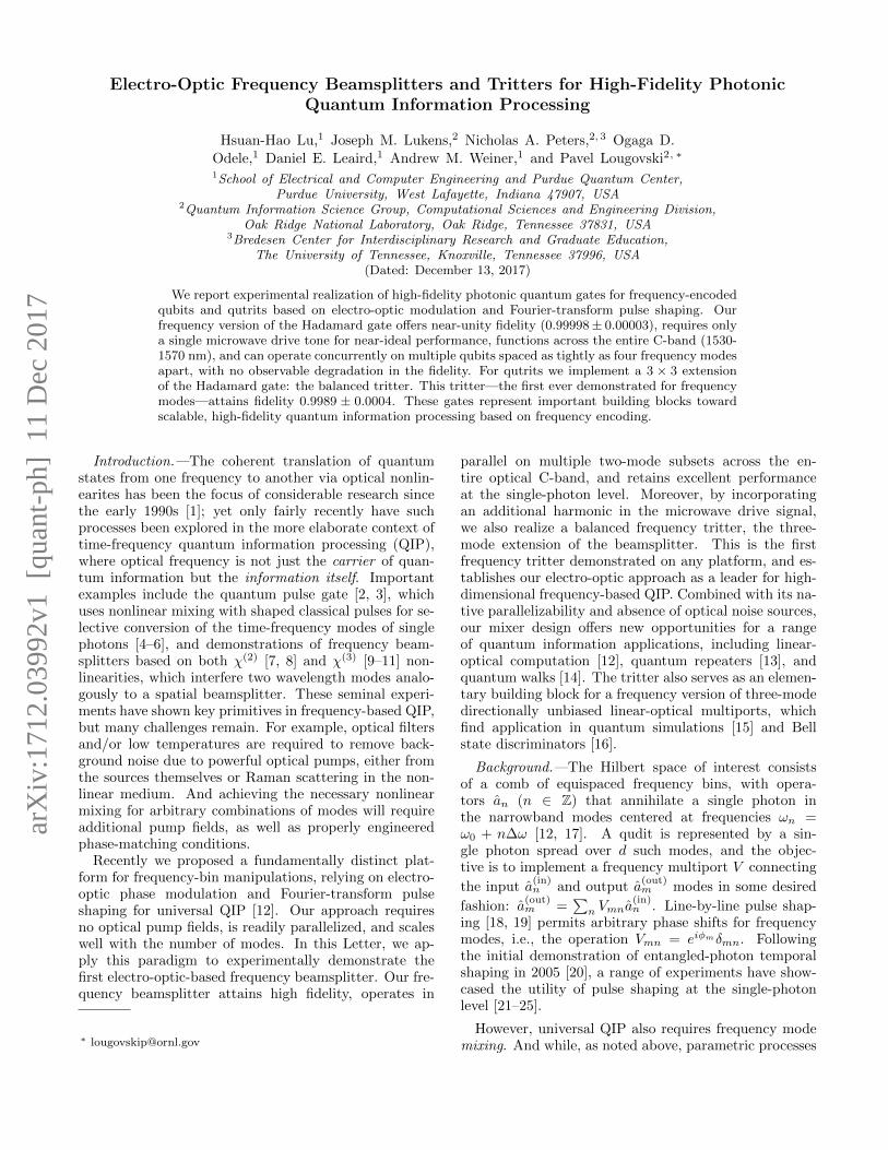
Figure 1 provides a schematic of the experimentalsetup (Appendix C). A radio-frequency (RF) oscilla-tor provides a 25-GHz drive signal to each EOM, withamplifiers and delay lines setting the appropriate ampli-tude and phase for each waveform. The central pulseshaper applies the numerically optimized spectral phasepattern for the Hadamard gate. The ∼10-GHz spec-tral resolution of this pulse shaper ultimately limits thetightest frequency-mode spacing (and thus total num-ber of modes) we can utilize in our setup; experimen-tally we have found detectable reduction in F and Pfor spacings below ∼18 GHz. To characterize the fullfrequency-bin multiport, we probe it with an electro-optic frequency comb, measuring the output spectrumfor different input frequency superpositions. This tech-nique represents the analogue of the spatial version pro-posed and demonstrated in [36], applied here for thefirst time to frequency modes (Appendix D). We alsoadopt the convention [36] which specifies zero phase asthe input superposition state that maximizes the powerin the zeroth frequency bin of the output; the phase val-ues of any subsequent state (as set by the state prepa-ration pulse shaper in Fig. 1) are thus only defined rel-ative to this operating point. At a center wavelengthof 1545.04 nm (ω0 = 2π × 194.036 THz), we measurefidelity F = 0.99998 ± 0.00003 and success probability
2x
RF Source
Optical Attenuator
Inte
nsity
Mod
ulat
or
CW
Las
er
Pul
se S
hape
r
EOM EOM
Pulse ShaperFrequency-Resolved
Detection
PowerSplitter
RF LEGEND
Amplifier
VariableAttenuator
PhaseShifter
2xFrequencyDoubler
For Tritter Only
Optical Path
RF Path
FREQUENCY MIXERSTATE
PREPARATION
FIG. 1. Experimental setup. See text and Appendix C fordetails.

3
P = 0.9739± 0.0003, where error bars give the standarddeviation of five independent measurement sequences.The current gate insertion loss is 12.5 dB: the EOMscontribute ∼2.8 dB each; the pulse shaper, ∼4.7 dB; andthe remainder comes from fiber patch cord connectionsand polarization controllers.
Figure 2 shows four experimentally recorded in-put/output combinations: the top row shows the equi-amplitude superpositions resulting from input in ei-ther mode 0 or mode 1; the second row reveals thesingle-wavelength output with the input in the states|αω0(±α)ω1〉. The small bumps in adjacent modes −1and +2 reflect the nonunity success probability, a limita-tion which—as noted above—could be removed by moresophisticated modulation waveforms. And even in thecurrent arrangement with P ≈ 0.97, the impact suchresidual scattering could have on gates downstream—i.e.,by coupling back into the computational space and in-troducing errors—can be eliminated, either by using thenext pulse shaper to selectively attenuate these modes,or by sending them to a fiber tap for detection.
A crucial claim in favor of our beamsplitter is its suit-ability for parallelization. Ironically, the very charac-teristic which precludes a deterministic frequency beam-splitter using a single EOM—frequency-translation in-variance (Appendix A)—enables nearly effortless paral-lelization. After properly compensating dispersion acrossthe optical spectrum (to synchronize group delay betweenthe two EOMs), we scan the wavelength of the centralgate mode in 5-nm increments and measure F and P ateach step over the full C-band. Figure 3(a) shows that thefidelity exceeds 0.9990 for all test points, and the successprobability does not drop below 0.965. A second ques-tion, complementary to the total acceptance bandwidth,
0
0.5
1
No
rma
lize
d I
nte
nsit
y [a
.u]
Input
Output
Input
Output
−2 −1 0 1 2 3
Mode Index n [(ω-ω )/Δω]o
0
0.5
1
Input
−2 −1 0 1 2 3
Input
OutputOutput
(a)
(d)(c)
(b)
FIG. 2. Experimentally measured beamsplitter output spec-tra for specific coherent state inputs. (a) Pure mode 0:|αω00ω1〉. (b) Pure mode 1: |0ω0αω1〉. (c) Mode 0 and mode1 in phase: |αω0αω1〉. (d) Mode 0 and mode 1 out of phase:|αω0(−α)ω1〉.
(b)
(a)
6
0.9992
0.9996
1.0000
Fid
elit
y
Wavelength [nm]1530 1540 1550 1560
0.967
0.971
0.975
Succe
ss Pro
bability
0 1 2 3 4 5Number of Guardband Modes
0.9
0.99
0.999
Fid
elit
y
0.9999
0
0.9
0.99 Succe
ss Pro
bability
FIG. 3. (a) Fidelity and success probability as a functionof center wavelength. (b) Parallel beamsplitter performanceagainst frequency separation.
is the minimum frequency spacing: how close can twosingle-qubit gates be placed without performance degra-dation? Since sidebands adjacent to the computationalspace are populated mid-calculation, one would expectthat a finite number of dark, guardband modes are re-quired to prevent cross-contamination. We address thisquestion experimentally by implementing two beamsplit-ters in parallel and characterizing the total operation asa function of the number of initially empty modes be-tween mode 1 of the low-frequency gate and mode 0 ofthe higher frequency one. The fidelity and success prob-ability for the collective parallel operation are plotted inFig. 3(b); they reach their asymptotic values for sepa-rations of just four modes. Combined with the 40-nm(5-THz) bandwidth of Fig. 3(a) and the 25-GHz modespacing, these results imply that the present system canrealize 33 frequency beamsplitters in parallel—a remark-able indication of the promise of our approach in scalableQIP.
Frequency tritter.—Thus far, quantum frequency mix-ers have focused on the basic two-mode case [7–11], yetthe inherent high dimensionality of frequency-bin statesmakes them well-suited for more complex qudit opera-tions as well. Accordingly, generalizing mode mixers todimensions beyond d = 2 represents an important mile-stone for frequency-based QIP. For d = 3, the most nat-ural operation is the uniform frequency tritter—the fre-quency analogue of a 3×3 spatial coupler with equal splitratios [37], which has been shown to enable fundamen-tally richer quantum physics than the two-mode case [38].The specificity of such an operation distinguishes the fre-quency tritter from previous examples of frequency con-version which, while involving three distinct modes, havenot attained arbitrary control over the full 3× 3 interac-tion [39]. For our purposes, a particularly convenient op-eration satisfying the equi-amplitude requirement is the

4
3-point discrete Fourier transform (DFT):
U3×3 =1√3
1 1 11 e2πi/3 e4πi/3
1 e4πi/3 e2πi/3
. (2)
Numerically, we find that incorporating an additionalharmonic in the EOM drive signals allows our currentconfiguration to reproduce the above frequency tritterwith predicted fidelity F = 0.9999 and success prob-ability P = 0.9733 (Appendix B). The fact thatthe modulation remains so simple even for the trit-ter operation—consisting of the sum of just two phase-shifted sinewaves—again manifests the fortuitous prac-ticality of our Fourier-series approach, beyond even theoriginal proposal which relied on specialized RF wave-forms [12].
Experimentally, we incorporate an RF frequency dou-bler into the setup (see dotted box in Fig. 1) to producethe necessary second harmonic. Because of the high-frequency rolloff of our microwave components, we alsoreduce the drive frequency—and hence, mode spacing—from 25 GHz to 18.1 GHz, for a doubled component at36.2 GHz [40]. Running the coherent-state-based char-acterization algorithm (Ref. [36] and Appendix D), wemeasure fidelity F = 0.9989 ± 0.0004 and success prob-ability P = 0.9730 ± 0.0002, again extremely close totheoretical predictions. Figure 4 plots several importantinput/output spectra: for any single-line input, the out-put exhibits equal lines in the same three modes; con-versely, three-mode input superpositions of the appropri-ate phases excite single lines at the output. This high-fidelity, balanced frequency tritter—the first of its kind—confirms that our electro-optic technique scales well to
0
0.5
1
No
rma
lize
d I
nte
nsit
y [a
.u]
Input
Output
−2 −1 0 1 2 3
Mode Index n [(ω-ω )/Δω]o
0
0.5
1Input
Output
(d)(c)
(b)Input
Output
4 −2 −1 0 1 2 3 4
(a)
Ⅰ Ⅱ Ⅲ
FIG. 4. Experimentally measured tritter output spec-tra for specific coherent-state inputs. (a) Pure mode 0:|αω00ω10ω2〉. (b) Pure mode 1: |0ω0αω10ω2〉. (c) Pure mode2: |0ω00ω1αω2〉. (d) Outputs for the superposition state input|αω0(e−iφα)ω1(e−2iφα)ω2〉 for: (I) φ = 0, (II) φ = 2π/3, and(III) φ = 4π/3.
higher dimensions, with only a minor increase in the sys-tem complexity.
Single-photon level.—Finally, to verify that these fre-quency mode mixers maintain performance at the single-photon level, we attenuate the input state |αω0(e−iφα)ω1〉for the beamsplitter and |αω0(e−iφα)ω1(e−2iφα)ω2〉 forthe tritter to ∼0.1 photons per detection window at thegate input (i.e., before loss through the frequency mixer)and scan the input phase φ. The resulting interferencepatterns for these weak coherent states allow us to predictoperation fidelity for true single-photon states as well.This follows because the gate itself is a one-photon op-eration, and thus the interference visibility depends onlyon the average flux and any extra noise introduced by thegate—not on the photon number statistics of the input.At each setting, we use a wavelength-selective switch todirect the output modes to a gated InGaAs single-photondetector. Figure 5(a) plots the counts in modes 0 and 1for the beamsplitter, after subtracting the average de-tector dark count rate (error bars give the standard de-viation of five repeated measurements). Moving on tothe three-mode case, we obtain the detection rates formodes 0, 1, and 2 shown in Fig. 5(b). The oscillationsnow trace a sum of two sines, with respective peaks atφ = 0, 2π/3, and 4π/3, as expected for the ideal matrixin Eq. (2). The reduced flux for mode 1 is primarilydue to the wavelength-selective switch, as its 12.5-GHzpassbands do not match the 18.1-GHz line spacing; in ourfilter definitions, the center of mode 1 is close to one pass-band edge, and thereby experiences an additional ∼1-dBattenuation. Overall, both the beamsplitter and trit-ter perform exceptionally well at the single-photon level,with detector-dark-count-subtracted visibilities from 97-100%. Such low-flux visibilities far exceed those of pre-vious χ(2) or χ(3) frequency beamsplitters, which sufferfrom optical noise generated by the powerful pump fields;our approach inherently contributes no excess noise pho-tons, making it particularly well-suited for quantum ap-
−1
Co
un
t R
ate
[s
]
0 1 2 3 4 5
Input Phase [rad]
400
0
200
6
300
100
0 1 2 3 4 5
1600
0
800
6
1200
400
Mode 0
Mode 1Mode 2
Mode 0
Mode 1
(a) (b)
FIG. 5. Spectral interference with weak coherent states. (a)Output count rates for the two frequency modes of the beam-splitter, as the phase φ of the single-photon-level state |ψ2〉is scanned. (b) Counts for the three output modes of the fre-quency tritter as the phase φ of the three-mode state |ψ3〉 isscanned. The plotted best-fit curves are Fourier series of theform
∑nAn cos(nφ + Bn), summed from n = 0 to 1 for (a),
and n = 0 to 2 for (b).

5
plications.Discussion.—A major goal moving forward would be
to fully integrate this frequency mixer, using on-chipmodulators and pulse shapers—not only for reducingoverall footprint but also lowering the current ∼12.5-dBinsertion loss, due primarily to our use of off-the-shelftelecommunication components. While our system’smassive bandwidth could soften the impact of loss in theshort term, through parallel replication of a desired oper-ation, the ideal solution would be to reduce the loss alto-gether by improved engineering. An on-chip EOM with∼1-dB loss has already been demonstrated [41], and anintegrated pulse shaper with only∼2-dB loss appears rea-sonable with established silicon-photonic processes [42].Without a doubt, significant challenges remain to syn-thesize these capabilities onto a monolithic platform, de-manding continued research and as-yet-uncharted tech-nological advances. But the current state of the art nev-ertheless provides legitimate promise for the developmentof high-throughput on-chip frequency gates, compatiblewith on-chip quantum frequency combs [43–47]. This in-tegration would be extremely valuable, as the importanceof electro-optic mixing has already been demonstrated inoff-chip probing of the frequency entanglement of suchfrequency combs [46, 47]. However, these examples usedonly one EOM and therefore suffered large amountsof scattering outside of the computational space (Ap-pendix A). By contrast, our multiple-EOM scheme per-mits inherently efficient true quantum gates—essentialfor the development of large-scale on-chip frequency QIPsystems.
Finally, we note a useful connection between ourelectro-optic results and previous parametric beamsplit-ters [7–11]. Since our technique excels for tightly spacedmodes operated in parallel, whereas nonlinearity-basedbeamsplitters instead perform well for interband modesspaced beyond typical electro-optic bandwidths, one canenvision integrating both approaches in the same system:computations can be performed in parallel within densesubbands with our technique, and the resulting photonicstates can then be spectrally combined by parametricfrequency mixers for further processing. In this way, theadvantages of both approaches can be leveraged simulta-neously, bringing us one step closer to the full utility ofphotonic QIP with frequency modes.
ACKNOWLEDGMENTS
We thank W. R. Ray for use of the optical spectrumanalyzer and N. Lingaraju for helpful discussions regard-ing on-chip photonics. This work was performed in partat Oak Ridge National Laboratory, operated by UT-Battelle for the U.S. Department of Energy under con-tract no. DE-AC05-00OR22725. Funding was providedby ORNL’s Laboratory Directed Research and Develop-ment Program and National Science Foundation grantECCS-1407620.
Appendix A: Single EOM and scatter probability
Consider an EOM driven with phase ϕ(t), assumedperiodic at the inverse mode spacing (T = 2π/∆ω).Then the input and output frequency modes are re-
lated according to a(out)m =
∑n cm−na
(in)n , where cn =
(2π)−1∫Tdt eiϕ(t)ein∆ωt are the Fourier series coefficients
of the periodic EOM operation. The ideal EOM is there-fore invariant to optical frequency translation; mathe-matically speaking, the operation is a Toeplitz (diagonal-constant) matrix, with coefficients depending only on thefrequency difference between input and output modes.Accordingly, any modulation which succeeds in coupling,say, mode n to n+1, will also couple modes n+1 to n+2with equal weight. In the case of a uniform mode mixer,this implies that a single EOM will necessarily scatter in-put photons out of the d-mode computational space intoadjacent sidebands. Because of the Toeplitz condition, anEOM that attains uniform amplitude for a d× d matrixmust have at least 2d− 1 equal coefficients in its Fourierseries (with additional sidebands to preserve unitarity).As d− 1 of these fall outside of the computational space,the scatter probability is at least (d − 1)/(2d − 1) for auniform d-mode mixer based on one EOM.
Appendix B: Optimization Approach
While our original spectral Hadamard gate makes useof two pairs of pulse shapers and EOMs [12], we notethat three total components (EOM-shaper-EOM) sufficeto perform the Hadamard gate with F = P = 1. Thisfollows from the fact that, since the input photon occu-pies just two frequency modes, any pair of phases appliedto these two modes by the first pulse shaper is indistin-guishable from a temporal delay: the spectral phase istrivially a linear function of frequency. Thus, any modu-lation that would have been applied by this pulse shapercan be absorbed into a delay on the first EOM. Underthis simplification, we can approximate the transforma-tion matrix for the frequency multiport V by
V = FD3F†D2FD1F
†, (B1)
where D1 and D3 (D2) are diagonal unitary matrices rep-resenting the temporal (spectral) phase modulations ap-plied by the EOMs (pulse shaper), and F is the M ×Mdiscrete Fourier transform (DFT). Truncating the ma-trix V to M modes provides an accurate approximationto the d× d operation of interest as long as M � d andthe solution does not experience aliasing—that is, sam-pling exceeds the Nyquist rate. In our simulations, weutilize the Optimization Toolbox in MATLAB to searchfor an optimal set of phases for D1, D2, and D3 whichpreserve fidelity F > 0.9999 and maximize success prob-ability P. In general, each matrix is characterized byM independent real numbers in (−π, π]: for the pulseshaper (D2), these signify the phase shifts applied to each

6
frequency mode; for the EOMs (D1 and D3), these aresamples of the temporal phase modulation over one pe-riod. However, for experimental practicability, we con-strain the temporal phase patterns to sums of sinewaves(i.e., truncated Fourier series), rather than fully arbi-trary functions. Thus, taking a total of p harmonicsin the optimization—each specified by an amplitude andphase—the number of free parameters for each EOM ma-trix reduces to 2p. In the following we set M = 128 andp = 1 for the frequency beamsplitter simulations, for atotal of M + 2(2p) = 132 numbers to find; for the fre-quency tritter, we add one more harmonic, giving p = 2and 136 total parameters.
Here we record the specific solutions for the pulseshaper and each EOM in the optimal frequency beam-splitter and tritter. Figures 6(a) and (b) show the re-sults for the frequency beamsplitter, with F = 0.9999and P = 0.9760. The temporal phases on both EOMsare just phase-shifted sinewaves driven by a single RFtone. In addition, the spectral phase on the pulse shaper,shown in Fig. 6(b), turns out to be a step function witha π-phase jump between mode indices 0 and 1, readilyimplemented in the line-by-line pulse shaping scheme.
Furthermore, additional simulations show that thisthree-element setup can implement the frequency DFTup to d = 7 while maintaining F × P > 0.97, using drivesignals consisting of only d− 1 single-frequency harmon-ics [48]. These findings indicate favorable scaling in ourparadigm, effectively sublinear in the number of compo-nents and preserving high F and P.
The solution for the frequency tritter is presented inFigs. 6(c) and (d). We incorporate an additional RFharmonic to both EOMs while maintaining the three-element setup, and numerically we achieve F = 0.9999and P = 0.9733. As shown in Fig. 6(c), the temporalphases are still time-shifted replicas, but now composedof two harmonics. The introduction of the additionalharmonic couples more optical power to high-frequencymodes, and relatively more complicated spectral phasecontrol is needed for the frequency tritter, as plotted inFig. 6(d). Note that both solutions are achievable experi-mentally: the maximum temporal phase shifts [Figs. 6(a)and (c)] are well within values available from commer-cial EOMs, and the number of frequency modes requir-ing spectral shaping is <∼ 20 [Figs. 6(b) and (d)]—muchless than the full M -mode space, indicating 128 samplesare fully sufficient to characterize the solution. This in-tuition is confirmed numerically; by inserting passbandswhich block all frequencies beyond a finite interior band,we find no reduction in either F or P to 6 significantdigits, when keeping just 8 modes for the beamsplittersolution and 16 modes for that of the tritter.
Ph
ase
[rad
]
0 0.5 1−1
0
1(a) (b)
−8 0 8−4 4−2
0
2
1
−1
Time t/T Mode Index n
Ph
ase
[rad
]
0 0.5 1−2
0
2(c) (d)
−16 0 16−8 8−3
0
3
Time t/T Mode Index n
FIG. 6. Numerical solutions for the time-frequency phasesrequired to implement optimal beamsplitter and tritter. Forthe frequency beamsplitter: (a) temporal phase modulationapplied to the first EOM [solid red] and second EOM [dottedblue], plotted over one period; (b) phases applied to eachfrequency mode by the pulse shaper, where modes 0 and 1denote the computational space. For the frequency tritter:(c) temporal phase modulation for first [solid red] and second[dotted blue] EOM; (d) phases applied to each frequency modeby the pulse shaper, where now modes 0, 1, and 2 denote thecomputational space.
Appendix C: Experimental Methods
1. Frequency Beamsplitter
In our experimental scheme (Fig. 1), the preparationof input states, frequency mixing, and final output statedetection are all built on commercial fiber-optics instru-mentation, such as intensity/phase modulators, pulseshapers and single-photon counters. The implementa-tion of the frequency beamsplitter can be described asfollows. A tunable continuous-wave (CW) laser operat-ing in the C-band is firstly sent to an intensity modula-tor (IM; Photline MX-LN-40) driven at 25 GHz, whichcreates a total number of three frequency bins with aspacing of 25 GHz. (The use of an intensity, rather thanphase, modulator was purely from equipment availability:a phase modulator would produce many more comblineswith greater efficiency, but the IM suffices for the num-ber of modes needed in this experiment.) The subse-quent pulse shaper (Finisar WaveShaper 1000S)—whichpossesses ∼10-GHz spectral resolution, 1-GHz address-ability, with operating wavelength from 1527.4 nm to1567.5 nm—then performs amplitude and phase filter-ing to prepare either pure mode or superposition statesas input to the following frequency beamsplitter. We usean RF oscillator (Agilent E8257D) to generate a 25-GHzsinewave, and split it three ways feeding amplifiers for

7
the first IM for state preparation and the two 40-Gb/sEOMs (EOSpace) of the frequency beamsplitter. Accu-rate control of the amplitude and the timing of RF signalsis achieved by the usage of variable attenuators and phaseshifters, by which we fine tune every RF component untilwe have correlation above 99.9% between the experimen-tally obtained intensity spectrum after each EOM andthe theoretical prediction. With estimated EOM half-wave voltages of Vπ = 5.37 V at 25 GHz, the total RFpower required at each EOM for the solution in Fig. 6(a)is roughly 12.9 dBm.
The central pulse shaper (another Finisar Wave-Shaper), applies the numerically obtained phase patterns[Fig. 6(b)], and for the parallelization tests (Fig. 3), italso compensates optical dispersion. Experimentally, wefound that applying a dispersion of −0.4 ps/nm was suf-ficient to compensate all frequency-dependent delay be-tween the two EOMs (including the residual dispersionin the pulse shaper itself) and thus ensure proper tim-ing between EOMs across the full C-band. Otherwise,the beasmplitter would not be able to preserve the cor-rect split ratio for all parallel gates simultaneously ; onthe other hand no dispersion compensation is neededfor a single gate, since frequency-dependent delay overthe bandwidth involved (∼6 modes or ∼1 nm) is muchsmaller than the 40-ps RF period. For output state detec-tion in the high-flux regime, we utilize an optical spec-trum analyzer (OSA; Yokogawa) to obtain five spectrafor each input state, and calculate the mean and stan-dard deviation for both F and P. For this coherent-satecharacterization, we set the CW laser power to about 5mW at the gate input.
In the weak-coherent-state experiment, the outputstate is frequency-demultiplexed by a frequency-selectiveswitch (Finisar WaveShaper 4000S), and measured byan InGaAs single-photon avalanche photodiode (AureaTechnology SPD AT M2), gated at 1.25 MHz, with a 1-ns gate and 20% detection efficiency. As the input stateis attenuated to ∼0.1 photons per detection window atthe gate input (inferred by the measured system loss anddetector parameters), we register ∼400 counts/s on thedetector. The dark count rate is measured when the laseris turned off and maximum (>35-dB) attenuation is seton the shaper; roughly 20 counts/s are registered. Foreach phase setting, we perform five 5-s measurements torecord mean photon counts and the error bars, subtractthe mean dark counts, and calculate the visibility of eachtrace with the Curve Fitting Toolbox in MATLAB, re-peating this for both frequency modes.
2. Frequency Tritter
For the frequency tritter, we incorporate an RF fre-quency doubler (Spacek Labs AQ-2X) to produce thenecessary second-harmonic signal. Due to a combina-tion of doubling efficiency and loss in current microwavecomponents, we chose for these experiments to operate
at 18.1-GHz mode spacing, rather than the beamsplit-ter’s 25 GHz. [No such reduction would be required withall-V-band (40-75 GHz) hardware.] Considering the pre-dicted EOM half-wave voltages at 18.1 and 36.2 GHz(Vπ = 4.78 and 6.02 V, respectively), the expected RFpower at the input of each EOM is 14.1 dBm at 18.1GHz and 7.89 dBm at 36.2 GHz. Also, because of therelative difficulty to manually phase shift both harmon-ics synchronously, we set the relative phase of the twocombined frequencies on both EOMs independently, thenmatch the overall delay between EOMs by applying ad-ditional linear spectral phase on the central pulse shaper.
The high-flux F and P measurements use the samemeasurement components as in the beamsplitter case.Yet for the single-photon-level tritter tests, demultiplex-ing is achieved with an amplitude-only wavelength se-lective switch (Finisar WSS) having 12.5-GHz channelspecificity across a total bandwidth of 4.825 THz, anddetection with an InGaAs photon counter operated at4-MHz gate frequency, 2.5-ns gate duration, and >10%efficiency (ID Quantique id-200). Such differences in de-multiplexing and detection explain why the overall countrates in the main text (Fig. 5) vary between the beam-splitter and tritter. Measuring dark counts with thesame procedure as with the beamsplitter, we obtain ∼150counts/s, which are subsequently subtracted from the to-tals.
Appendix D: Procedure for MeasuringTransformation Matrix
Our calculations of F and P rely on complete char-acterization of the d × d multiport Vd×d. We utilize ananalogue of the spatial technique shown in Ref. [36], andhere we provide additional details on precisely how todetermine each of the matrix elements. This techniquerelies on high-power coherent state probing, which is jus-tified because the operation of interest is, at its basiclevel, a linear multiport; thus its distinguishing behav-ior holds for high-flux coherent states as well as singlephotons.
The definition of success probability P is
P =1
dTr(V †d×dVd×d), (D1)
where Vd×d denotes the infinite-dimensional transforma-tion V truncated to the d modes of the desired operationUd×d. This can be written equivalently as
P =1
d
d−1∑m=0
d−1∑n=0
|Vnm|2, (D2)
from which we see that P depends on only the moduli ofthe d2 matrix elements. To find these values, we probeour frequency multiport with a single optical frequencyfrom index n = 0 to d − 1. The information we need tocalculate P, namely |Vmn|2, is then given by the output

2× 2
3× 3
2× 2
8
optical power in mode m when the input is set to n.And by measuring the total throughput of the system inall modes (even those beyond d), we can normalize eachmatrix element by overall transmissivity, distinguishingthe insertion loss (photon is missing) from scatter loss(photon remains, but has left d-dimensional subspace),so that P can quantify the latter. Thus, a value P = 1means that, given that the input photon exits the system,it is guaranteed to have undergone the desired operationand has remained in the d-mode computational subspace.
On the other hand, the fidelity F involves the fullHilbert-Schmidt inner product:
F =1
d
|Tr(V †d×dUd×d)|2
Tr(V †d×dVd×d), (D3)
or alternatively
F =1
d2P
∣∣∣∣∣d−1∑m=0
d−1∑n=0
V ∗nmUnm
∣∣∣∣∣2
, (D4)
which indeed depends on the phase as well as ampli-tude information of Vd×d. To determine these phases,we next probe the setup with superpositions of two fre-quency modes, scanning the relative phase φ from 0 to2π. Extracting the power on specific modes from a seriesof optical spectra yields interference patterns over φ, and
the unknown phase terms in Vd×d can be obtained byperforming sinusoidal fitting on each curve.
In our experiments, we apply the above techniqueto d = 2 (beamsplitter) and d = 3 (tritter).The corresponding frequency multiport matrices areV2×2 and V3×3, and the input optical field E(t) =∑d−1m=0
√pme
iφme−iωnt can be expressed in mode ma-
trix form as [√p0e
iφ0√p1e
iφ1 · · · √pd−1eiφd−1 ]T . We
write a general matrix element of Vd×d in polar form asVmn = rmne
iφmn . Since phase is only physically mean-ingful up to a unitary rotation, we follow the procedureof Ref. [36] and define the phases of the first row and col-umn as zero: this effectively provides a reference for zerophase on our input state preparation. Finally, though thematrices in the following equations are expressed in d di-mensions for brevity, experimentally the optical powercan be scattered out of the d-mode computational spaceinto adjacent sidebands. Therefore, the sensitivity of theOSA should be high enough so that we can collect theoptical power in as many modes as possible for accuratenormalization. Experimentally, we found that only 6-8modes were needed to encompass all the optical power(to within 10−4 accuracy).
The test cases for a single-frequency-mode probe are(note that the OSA functions as a frequency-resolvedsquare-law detector):
[r00 r01
r10 r11eiφ11
] [√p
0
]=√p
[r00
r10
]OSA−−−→ p
[r200
r210
][r00 r01
r10 r11eiφ11
] [0√p
]=√p
[r01
r11eiφ11
]OSA−−−→ p
[r201
r211
]r00 r01 r02
r10 r11eiφ11 r12e
iφ12
r20 r21eiφ21 r22e
iφ22
√p00
=√p
r00
r10
r20
OSA−−−→ p
r200
r210
r220
r00 r01 r02
r10 r11eiφ11 r12e
iφ12
r20 r21eiφ21 r22e
iφ22
0√p
0
=√p
r01
r11eiφ11
r21eiφ21
OSA−−−→ p
r201
r211
r221
r00 r01 r02
r10 r11eiφ11 r12e
iφ12
r20 r21eiφ21 r22e
iφ22
00√p
=√p
r02
r12eiφ12
r22eiφ22
OSA−−−→ p
r202
r212
r222
(D5)
We thus see that by these measurements we can obtain all d2 amplitudes of Vd×d. Subsequently, we probe the systemwith superpositions of two frequency modes, and scan the relative phase φ ∈ [0, 2π] between them. The differentconfigurations are:
[r00 r01
r10 r11eiφ11
] [ √p√peiφ
]=√p
[r00 + r01e
iφ
r10 + r11ei(φ+φ11)
]OSA−−−→ p
[r200 + r2
01 + 2r00r01 cosφr210 + r2
11 + 2r10r11 cos(φ+ φ11)
]

3× 3
9
r00 r01 r02
r10 r11eiφ11 r12e
iφ12
r20 r21eiφ21 r22e
iφ22
√p√peiφ
0
=√p
r00 + r01eiφ
r10 + r11ei(φ+φ11)
r20 + r21ei(φ+φ21)
OSA−−−→ p
r200 + r2
01 + 2r00r01 cosφr210 + r2
11 + 2r10r11 cos(φ+ φ11)r220 + r2
21 + 2r20r21 cos(φ+ φ21)
r00 r01 r02
r10 r11eiφ11 r12e
iφ12
r20 r21eiφ21 r22e
iφ22
√p0√peiφ
=√p
r00 + r02eiφ
r10 + r12ei(φ+φ12)
r20 + r22ei(φ+φ22)
OSA−−−→ p
r200 + r2
02 + 2r00r02 cosφr210 + r2
12 + 2r10r12 cos(φ+ φ12)r220 + r2
22 + 2r20r22 cos(φ+ φ22)
(D6)
For each curve, we then perform sinusoidal fitting withrespect to the input phase φ and obtain all the phasevalues in Vd×d. And from this, we can calculate fidelityF .
To give an idea of what our measurements produce, weprovide two examples of matrices obtained using the pre-vious characterization method. An example mode trans-formation for the beamsplitter is
V2×2 =
[√0.4871
√0.4869√
0.4866√
0.4871ei3.1400
]. (D7)
These values correspond to P = 0.9739 and F = 0.9999when compared to the ideal Hadamard gate. Error barsfrom repeating the full characterization four more times
then gave P = 0.9739±0.0003 and F = 0.99998±0.00003.
For the three-mode DFT, an example transformationmeasured is
V3×3 =
√0.3261√
0.3126√
0.3062√0.3183
√0.3290ei2.0925
√0.3339ei4.1775
√0.3202
√0.3476ei4.1365
√0.3256ei2.0425
,(D8)
with associated success P = 0.9731 and fidelity F =0.9992 with respect to the perfect (i.e., not numericallysimulated) DFT matrix. Averaging over five repeatedmeasurements then yielded P = 0.9730±0.0002 and F =0.9989± 0.0004, as in the main text.
[1] J. Huang and P. Kumar, Phys. Rev. Lett. 68, 2153(1992).
[2] B. Brecht, A. Eckstein, A. Christ, H. Suche, and C. Sil-berhorn, New J. Phys. 13, 065029 (2011).
[3] A. Eckstein, B. Brecht, and C. Silberhorn, Opt. Express19, 13770 (2011).
[4] B. Brecht, A. Eckstein, R. Ricken, V. Quiring, H. Suche,L. Sansoni, and C. Silberhorn, Phys. Rev. A 90, 030302(2014).
[5] P. Manurkar, N. Jain, M. Silver, Y.-P. Huang, C. Lan-grock, M. M. Fejer, P. Kumar, and G. S. Kanter, Optica3, 1300 (2016).
[6] V. Ansari, M. Allgaier, L. Sansoni, B. Brecht,J. Roslund, N. Treps, G. Harder, and C. Silberhorn,arXiv:1607.03001v1 (2016).
[7] T. Kobayashi, R. Ikuta, S. Yasui, S. Miki, T. Yamashita,H. Terai, T. Yamamoto, M. Koashi, and N. Imoto, Nat.Photon. 10, 441 (2016).
[8] T. Kobayashi, D. Yamazaki, K. Matsuki, R. Ikuta,S. Miki, T. Yamashita, H. Terai, T. Yamamoto,M. Koashi, and N. Imoto, Opt. Express 25, 12052 (2017).
[9] H. J. McGuinness, M. G. Raymer, C. J. McKinstrie, andS. Radic, Phys. Rev. Lett. 105, 093604 (2010).
[10] S. Clemmen, A. Farsi, S. Ramelow, and A. L. Gaeta,Phys. Rev. Lett. 117, 223601 (2016).
[11] C. Joshi, A. Farsi, and A. Gaeta, in CLEO: 2017 (Op-tical Society of America, 2017) p. FF2E.3.
[12] J. M. Lukens and P. Lougovski, Optica 4, 8 (2017).[13] K. Azuma, K. Tamaki, and H.-K. Lo, Nat. Commun. 6,
6787 (2015).[14] M. Hillery, J. Bergou, and E. Feldman, Phys. Rev. A
68, 032314 (2003).[15] D. S. Simon, C. A. Fitzpatrick, S. Osawa, and A. V.
Sergienko, Phys. Rev. A 95, 042109 (2017).[16] D. S. Simon, C. A. Fitzpatrick, and A. V. Sergienko,
Phys. Rev. A 93, 043845 (2016).[17] L. Olislager, J. Cussey, A. T. Nguyen, P. Emplit, S. Mas-
sar, J.-M. Merolla, and K. P. Huy, Phys. Rev. A 82,013804 (2010).
[18] S. T. Cundiff and A. M. Weiner, Nat. Photon. 4, 760(2010).
[19] A. M. Weiner, Opt. Commun. 284, 3669 (2011).[20] A. Pe’er, B. Dayan, A. A. Friesem, and Y. Silberberg,
Phys. Rev. Lett. 94, 073601 (2005).[21] F. Zah, M. Halder, and T. Feurer, Opt. Express 16,
16452 (2008).[22] C. Bernhard, B. Bessire, T. Feurer, and A. Stefanov,
Phys. Rev. A 88, 032322 (2013).[23] J. M. Lukens, A. Dezfooliyan, C. Langrock, M. M. Fejer,
D. E. Leaird, and A. M. Weiner, Phys. Rev. Lett. 111,193603 (2013).
[24] J. M. Lukens, A. Dezfooliyan, C. Langrock, M. M. Fejer,D. E. Leaird, and A. M. Weiner, Phys. Rev. Lett. 112,133602 (2014).
[25] A. Agarwal, J. M. Dailey, P. Toliver, and N. A. Peters,Phys. Rev. X 4, 041038 (2014).
[26] P. Kolchin, C. Belthangady, S. Du, G. Y. Yin, and S. E.Harris, Phys. Rev. Lett. 101, 103601 (2008).

10
[27] C. Belthangady, C.-S. Chuu, I. A. Yu, G. Y. Yin, J. M.Kahn, and S. E. Harris, Phys. Rev. Lett. 104, 223601(2010).
[28] C. Liu, Y. Sun, L. Zhao, S. Zhang, M. M. T. Loy, andS. Du, Phys. Rev. Lett. 113, 133601 (2014).
[29] M. Karpinski, M. Jachura, L. J. Wright, and B. J. Smith,Nat. Photon. 11, 53 (2017).
[30] L. J. Wright, M. Karpinski, C. Soller, and B. J. Smith,Phys. Rev. Lett. 118, 023601 (2017).
[31] S. E. Harris, Phys. Rev. A 78, 021807 (2008).[32] S. Sensarn, G. Y. Yin, and S. E. Harris, Phys. Rev. Lett.
103, 163601 (2009).[33] C. Belthangady, S. Du, C.-S. Chuu, G. Y. Yin, and S. E.
Harris, Phys. Rev. A 80, 031803 (2009).[34] J. M. Lukens, O. D. Odele, D. E. Leaird, and A. M.
Weiner, Opt. Lett. 40, 5331 (2015).[35] D. B. Uskov, L. Kaplan, A. M. Smith, S. D. Huver, and
J. P. Dowling, Phys. Rev. A 79, 042326 (2009).[36] S. Rahimi-Keshari, M. A. Broome, R. Fickler,
A. Fedrizzi, T. C. Ralph, and A. G. White, Opt. Ex-press 21, 13450 (2013).
[37] A. Zeilinger, H. Bernstein, D. Greenberger, M. Horne,and M. Zukowski, in Quantum Control and Measurement,edited by H. Ezawa and Y. Murayama (Elsevier, 1993)pp. 9–22.
[38] A. J. Menssen, A. E. Jones, B. J. Metcalf, M. C. Tichy,S. Barz, W. S. Kolthammer, and I. A. Walmsley, Phys.Rev. Lett. 118, 153603 (2017).
[39] I. Agha, M. Davanco, B. Thurston, and K. Srinivasan,Opt. Lett. 37, 2997 (2012).
[40] Higher frequencies could be obtained by using appropri-ate V-band (40-75 GHz) hardware.
[41] L. Fan, C.-L. Zou, M. Poot, R. Cheng, X. Guo, X. Han,and H. X. Tang, Nat. Photon. 10, 766 (2016).
[42] AIM Photonics, “Process design kit,” http://www.
aimphotonics.com/pdk/ (2017).[43] D. Grassani, S. Azzini, M. Liscidini, M. Galli, M. J.
Strain, M. Sorel, J. E. Sipe, and D. Bajoni, Optica 2, 88(2015).
[44] C. Reimer, M. Kues, P. Roztocki, B. Wetzel, F. Grazioso,B. E. Little, S. T. Chu, T. Johnston, Y. Bromberg,L. Caspani, D. J. Moss, and R. Morandotti, Science351, 1176 (2016).
[45] J. A. Jaramillo-Villegas, P. Imany, O. D. Odele, D. E.Leaird, Z.-Y. Ou, M. Qi, and A. M. Weiner, Optica 4,655 (2017).
[46] P. Imany, J. A. Jaramillo-Villegas, O. D. Odele, K. Han,M. Qi, D. E. Leaird, and A. M. Weiner, in Conference onLasers and Electro-Optics (Optical Society of America,2017) p. JTh5B.3; arXiv:1707.02276v1.
[47] M. Kues, C. Reimer, P. Roztocki, L. R. Corts, S. Sciara,B. Wetzel, Y. Zhang, A. Cino, S. T. Chu, B. E. Little,D. J. Moss, L. Caspani, J. Azana, and R. Morandotti,Nature 546, 622 (2017).
[48] Manuscript in preparation.