Quality of Service (QoS) in ARM Systems: An Overview · Quality of Service (QoS) mechanisms seek to...
8
Copyright © 2014 ARM Limited. All rights reserved. The ARM logo is a registered trademark of ARM Ltd. All other trademarks are the property of their respective owners and are acknowledged Page 1 of 8 Quality of Service (QoS) in ARM ® Systems: An Overview Ashley Stevens Senior FAE, Systems IP July 2014 Introduction Whether it’s the latest consumer multimedia device with ultra-high resolution display, or high- performance, long up-time enterprise hardware, almost all performance-oriented SoC systems are dependent on high bandwidth and low latency external memory systems to deliver within cost and performance boundaries. With the cost and power of adding additional or higher performance memory controllers being prohibitive in many or indeed most cases, schemes that can get the best performance from existing or more modest memory systems are desirable. Quality-of-Service (QoS) in the SoC interconnect and memory controller simultaneously enables low latency for highly latency-sensitive masters like CPUs, hard real-time demands from real-time devices and sufficient but not excessive bandwidth for potentially greedy masters like GPUs and high-performance DMAs. Various QoS mechanisms are supported within ARM ® System on Chip (SoC) IP. This paper presents an overview of the mechanisms available for the SoC designer to chose from and discusses the scenarios where they may be most advantageous. Quality of Service (QoS) Mechanisms For the purposes of QoS analysis a system can be considered as a transaction initiator, requestor or in AMBA ® 4 terms a ‘master’, an interconnect network and a transaction responder, target or in AMBA 4 terms a ‘slave’. Masters can be categorized into three broad classes: 1. Latency-sensitive masters 2. Greedy masters (or bulk transfer) 3. Real-time masters
Transcript of Quality of Service (QoS) in ARM Systems: An Overview · Quality of Service (QoS) mechanisms seek to...

Copyright © 2014 ARM Limited. All rights reserved. The ARM logo is a registered trademark of ARM Ltd.
All other trademarks are the property of their respective owners and are acknowledged
Page 1 of 8
Quality of Service (QoS) in ARM®
Systems: An Overview
Ashley Stevens
Senior FAE, Systems IP
July 2014
Introduction Whether it’s the latest consumer multimedia device with ultra-high resolution display, or high-performance, long up-time enterprise hardware, almost all performance-oriented SoC systems are dependent on high bandwidth and low latency external memory systems to deliver within cost and performance boundaries. With the cost and power of adding additional or higher performance memory controllers being prohibitive in many or indeed most cases, schemes that can get the best performance from existing or more modest memory systems are desirable. Quality-of-Service (QoS) in the SoC interconnect and memory controller simultaneously enables low latency for highly latency-sensitive masters like CPUs, hard real-time demands from real-time devices and sufficient but not excessive bandwidth for potentially greedy masters like GPUs and high-performance DMAs. Various QoS mechanisms are supported within ARM® System on Chip (SoC) IP. This paper presents an overview of the mechanisms available for the SoC designer to chose from and discusses the scenarios where they may be most advantageous. Quality of Service (QoS) Mechanisms For the purposes of QoS analysis a system can be considered as a transaction initiator, requestor or in AMBA® 4 terms a ‘master’, an interconnect network and a transaction responder, target or in AMBA 4 terms a ‘slave’. Masters can be categorized into three broad classes:
1. Latency-sensitive masters 2. Greedy masters (or bulk transfer) 3. Real-time masters
Copyright © 2014 ARM Limited. All rights reserved. The ARM logo is a registered trademark of ARM Ltd.
All other trademarks are the property of their respective owners and are acknowledged
Page 2 of 8
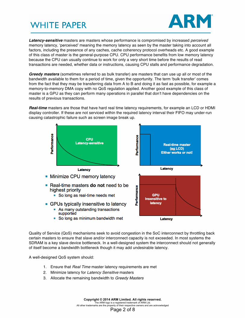
Latency-sensitive masters are masters whose performance is compromised by increased perceived memory latency, ‘perceived’ meaning the memory latency as seen by the master taking into account all factors, including the presence of any caches, cache coherency protocol overheads etc. A good example of this class of master is the general-purpose CPU. CPU performance benefits from low memory latency because the CPU can usually continue to work for only a very short time before the results of read transactions are needed, whether data or instructions, causing CPU stalls and performance degradation.
Greedy masters (sometimes referred to as bulk transfer) are masters that can use up all or most of the bandwidth available to them for a period of time, given the opportunity. The term ‘bulk transfer’ comes from the fact that they may be transferring data from A to B and doing it as fast as possible, for example a memory-to-memory DMA copy with no QoS regulation applied. Another good example of this class of master is a GPU as they can perform many operations in parallel that don’t have dependencies on the results of previous transactions. Real-time masters are those that have hard real time latency requirements, for example an LCD or HDMI display controller. If these are not serviced within the required latency interval their FIFO may under-run causing catastrophic failure such as screen image break up.
Quality of Service (QoS) mechanisms seek to avoid congestion in the SoC interconnect by throttling back certain masters to ensure that slave and/or interconnect capacity is not exceeded. In most systems the SDRAM is a key slave device bottleneck. In a well-designed system the interconnect should not generally of itself become a bandwidth bottleneck though it may add undesirable latency. A well-designed QoS system should:
1. Ensure that Real Time master latency requirements are met 2. Minimize latency for Latency Sensitive masters 3. Allocate the remaining bandwidth to Greedy Masters

Copyright © 2014 ARM Limited. All rights reserved. The ARM logo is a registered trademark of ARM Ltd.
All other trademarks are the property of their respective owners and are acknowledged
Page 3 of 8
…in that order. Of course there’s a certain trade-off to be had between #2 and #3 in terms of how much bandwidth the architect is willing to give up to reduce latency for latency-sensitive masters but #1 is always the primary concern.
SDRAM controllers commonly contain transaction queues that enable out-of-order return of transactions (subject to ordering constraints) that seek to maximize efficiency and/or performance by optimizing ordering based on known SDRAM state, such as page open status. QoS mechanisms seek to ensure that high-priority transactions can always reach the SDRAM queue and prevent interconnect congestion. Priority and Arbitration using QoS Priority Value Priority is indicated on AMBA 4 AXI using a 4 bit QoS Priority Value. Masters are assigned to one or more priority levels, indicated using the QoS 4 bit field. Transactions emanating from the master do so with a particular QoS value. Arbitration that takes place within the interconnect network and within slaves supporting out-of-order return takes into account the QoS priority. In the ARM CoreLink™ NIC-400 network interconnect and CCI-400 Cache Coherent Network, masters with the same QoS value are deemed within the same priority group and arbitration between these masters proceeds on a round-robin basis. Any priority system should take info account the possibility that low priority masters may starve. In the ARM DMC-400 for example a timeout can be programmed to raise the priority of a low priority master if it’s been waiting for an excessive period. Regulation-based mechanisms Regulation-based mechanisms seek to prevent congestion by limiting the rate and/or number of transactions injected into the interconnect. By putting limits on the number of transactions that can be injected into the system from masters, system resources (memory controller and interconnect) can be reserved for higher priority transactions. Issue Rate Regulation Mechanisms TSPEC Transaction Specification Regulation TSPEC regulation can be useful for isochronous masters that need a constant rate of data flow (‘Isochronous’ means at a constant rate). Video controllers, display controllers and audio input/output are good examples of constant rate or isochronous devices. It can also be used as a mechanism to place an upper limit on the bandwidth of greedy masters such as memory-to-memory DMA controllers, where there’s a requirement to put a maximum bandwidth limit on the device to prevent it from saturating the interconnect and/or the memory controller. TSPEC gets its name from ‘Traffic Specification’ regulation typically used in communications networks like the internet. TSPEC regulation works by specifying a desired transaction rate. Ie a specified time between transaction initiation. That said, if it ‘gets behind’ on transaction completion (due to other traffic causing congestion within the network) then there’s a certain amount of ‘catching up’ allowed, which is specified in the burstiness parameter. In more detail, TSPEC allows the user to specify a target average transaction rate. If the master ‘gets behind’ (in terms over transactions completed over time) then it can catch up, limited by the maximum number of catch-up transactions allowed in the burstiness parameter and an optional faster maximum peak rate during catch up mode which prevents the master taking exclusive control of the network, which otherwise would be possible if the master is the highest priority or very high priority device on the network during the catch-up phase.
Copyright © 2014 ARM Limited. All rights reserved. The ARM logo is a registered trademark of ARM Ltd.
All other trademarks are the property of their respective owners and are acknowledged
Page 4 of 8
Outstanding Transaction Regulation Outstanding transaction regulation limits the number of simultaneous outstanding transactions from a master that supports them in large numbers. Masters with this capability typically generate transactions that do not depend on previous transactions, like GPUs, DSP and DMAs. Outstanding transaction regulation is a flexible mechanism that regulates the bandwidth of such masters in periods of high system load whilst enabling them to better exploit system resources when the rest of the system is less highly stressed. As the (integer) number of outstanding transactions is quite a coarse variable, ARM QoS mechanisms implement fractional outstanding transaction regulation where the number of transactions permitted constantly oscillates between two fixed integer values separated by 1. For example 2.5 is achieved by a 50:50 mark:space ration between 2 and 3 outstanding transactions. Dynamic priority-based mechanisms Priority-based mechanisms dynamically vary the QoS priority value to achieve desired target average transaction latency or long term average bandwidth. Note that schemes that vary the QoS value cannot guarantee the latency of any given particular transaction and therefore are not generally useful for real-time masters. These schemes are good for devices that require a desired long-term average latency and/or bandwidth. There’s two dynamic priority based schemes. Both these schemes rely on programming a target latency parameter and then varying the QoS parameter to achieve the target within a feedback loop. A scaling register is used to control how quickly the priority is varied. If the QoS parameter is varied too quickly then it may start to oscillate between very high and very low priority. If it’s too low then it may take a long time to lock onto a suitable QoS value and to re-lock if conditions in the system change. Min and max range parameters are used to control the maximum and minimum values of QoS used for transactions. This ensures that QoS value adjusts only within a defined range and can’t equal or exceed the priority of top priority devices nor end up the lowest priority, if that’s the desired intention. Transaction Latency-based priority regulation This scheme measures the time between a transaction initiation and transaction completion, thus measuring transaction latency. The QoS priority value is then adjusted up or own down to in order to match the desired target latency as closely as possible within the maximum and minimum range that’s been defined. The adjustment amount is programmable. Address Request Latency-based priority regulation This scheme measures the time between the previous transaction initiation and the next transaction initiation. The QoS priority value is then adjusted up or own down to in order to match the desired target latency as closely as possible within the maximum and minimum range that’s been defined. It’s therefore similar to the transaction latency regulation but because it measures time between transactions it’s more akin to and bandwidth target than a latency target. As with transaction latency regulation the adjustment amount is programmable. Credit-based mechanisms QoS Virtual Networks (QVN) in AMBA 4 AXI QoS Virtual Networks (QVN) are a mechanism to prevent blocking in the interconnect. In a system with a memory controller with a re-ordering queue and that accepts multiple outstanding transactions, QVN enables the memory controller to reserve a certain number of transactions slots for high priority masters. In a system with QVN, the memory controller hands out ‘credits’ (or tokens) to masters and a master must obtain a credit before initiating a transaction. QVN puts the slave in control and ensures that transactions are not initiated unless they can be accepted at their destination, thus ensuring that transactions don’t back up and block the interconnect causing ‘head-of-line blocking’ (lower priority transactions blocking

Copyright © 2014 ARM Limited. All rights reserved. The ARM logo is a registered trademark of ARM Ltd.
All other trademarks are the property of their respective owners and are acknowledged
Page 5 of 8
higher priority transactions behind them in the interconnect). More information on QVN can be found in my white paper entitled “Introduction to QoS Virtual Networks (QVN)” here: http://community.arm.com/servlet/JiveServlet/previewBody/7958-102-2-12820/QVN-Introduction-CC.pdf QoS Regulators in Practice
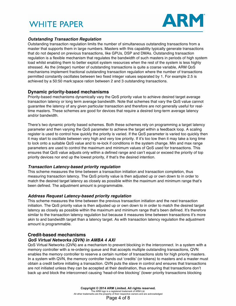
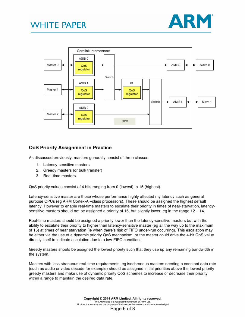
A QoS regulator is not a standalone IP block, it’s part of a Corelink network interconnect, such as the ARM CoreLink NIC-400 Interconnect. To use advanced QoS features with regulators (as opposed to just fixed priority or priority fed in from external signalling) then the NIC-400 requires the QoS-400 feature to be enabled, which is a separate FlexLM license feature in the AMBA Designer graphical environment. In the screenshot below you can see that the Advanced Quality of Service QoS-400 feature license is present and OK as indicated by the box with a small white check-mark. If you don’t see the check-mark then the QoS regulators can’t be instantiated in the NIC-400 interconnect.
In the ARM CoreLink NIC-400 interconnect the QoS regulators primarily reside in the AMBA Slave Interface Block (ASIB) which is a slave interface that connects to an external AMBA master. That is, they reside on the transaction-level inputs to the interconnect. In the case of a multi-level hierarchical interconnect QoS regulators may also reside in an internal Interface Block (IB) which is the block between two switches within the overall NIC-400 hierarchical interconnect. A QoS regulator in the ASIB can be used to regulate a master that it’s connected to externally. A QoS regulator in an IB can regulate a group of upstream masters as one. QoS regulation can be applied to the read channel, to the write channel, or a combined regulation limit for reads and writes is available.
Copyright © 2014 ARM Limited. All rights reserved. The ARM logo is a registered trademark of ARM Ltd.
All other trademarks are the property of their respective owners and are acknowledged
Page 6 of 8
Master 0
Master 1
ASIB 0
QoS regulator
ASIB 1
QoS regulator
Switch
ASIB 2
QoS regulator
IB
QoS regulator
AMIB0
Switch AMIB1
Master 2
Slave 0
Slave 1
Corelink Interconnect
GPV
QoS Priority Assignment in Practice As discussed previously, masters generally consist of three classes:
1. Latency-sensitive masters 2. Greedy masters (or bulk transfer) 3. Real-time masters
QoS priority values consist of 4 bits ranging from 0 (lowest) to 15 (highest).
Latency-sensitive master are those whose performance highly affected my latency such as general purpose CPUs (eg ARM Cortex-A –class processors). These should be assigned the highest default latency. However to enable real-time masters to escalate their priority in times of near-starvation, latency-sensitive masters should not be assigned a priority of 15, but slightly lower, eg in the range 12 – 14.
Real-time masters should be assigned a priority lower than the latency-sensitive masters but with the ability to escalate their priority to higher than latency-sensitive master (eg all the way up to the maximum of 15) at times of near starvation (ie when there’s risk of FIFO under-run occurring). This escalation may be either via the use of a dynamic priority QoS mechanism, or the master could drive the 4-bit QoS value directly itself to indicate escalation due to a low-FIFO condition.
Greedy masters should be assigned the lowest priority such that they use up any remaining bandwidth in the system.
Masters with less strenuous real-time requirements, eg isochronous masters needing a constant data rate (such as audio or video decode for example) should be assigned initial priorities above the lowest priority greedy masters and make use of dynamic priority QoS schemes to increase or decrease their priority within a range to maintain the desired data rate.

Copyright © 2014 ARM Limited. All rights reserved. The ARM logo is a registered trademark of ARM Ltd.
All other trademarks are the property of their respective owners and are acknowledged
Page 7 of 8
Combining Multiple QoS Strategies Simultaneously
QoS schemes are not mutually exclusive; it’s possible to use more than one scheme simultaneously. In the CoreLink NIC-400 Interconnect it’s possible to insert all types of regulators within the RTL and then enable or disable then as well as program their parameters in software. Each regulator in the NIC-400 adds around 2K gates or so, so it’s not a huge area burden to incorporate them all, which increases flexibility in final silicon as various schemes can be experimented with.
There are various combinations of QoS schemes that could make sense. For example TSPEC regulation sets an upper bound on the bandwidth that a master can take. TSPEC regulation can therefore be used to set an upper bound on the total traffic that a master can take. This could be combined with another scheme such as a dynamic priority based scheme that alters priority to achieve a target latency or bandwidth. Since these schemes don’t guarantee anything about instantaneous bandwidth or latency but only average, it’s reasonable to combine with TSPEC regulation, where the maximum bandwidth defined by TSPEC is higher than the target bandwidth define by dynamic priority regulation, to ensure that the desired peak maximum is never exceeded. There are other combinations of multiple QoS schemes that can make sense. Generally two schemes targeting the same bandwidth or latency target would not make much sense, rather one setting a target average and another setting a minimum or maximum could be advantageous.

Copyright © 2014 ARM Limited. All rights reserved. The ARM logo is a registered trademark of ARM Ltd.
All other trademarks are the property of their respective owners and are acknowledged
Page 8 of 8
Summary and Conclusions
Advanced QoS schemes build on simple priority based systems with the addition of QoS regulators, which limit traffic based number of outstanding transactions, frequency of issue of transactions, or on dynamic priority. QVN prevents memory controller and interconnect transaction back-up thereby preventing blocking in the interconnect. Multiple QoS systems may be instantiated in the same SoC, indeed even operating on the same master, and may be used individually or in combination to achieve the desired results.
Appendix: Summary of QoS Features in ARM CoreLink™ Family Products
Product QoS Priority Value
Address Latency Priority
Transaction Latency Priority
(Bandwidth)
Outstanding Transaction Regulation
TSPEC QVN
NIC-3011
✔ ✔ ✔ ✔
NIC-4002
✔ ✔ ✔ ✔ ✔ ✔
CCI-4003
✔ ✔ ✔ ✔ ✔
DMC-4004
✔ * * ✔
• Indirectly supports the feature, regulators are in the interconnect
1 - CoreLink NIC-301 Configurable Network Interconnect 2 - CoreLink NIC-400 Configurable Network Interconnect 3 - CoreLink CCI-400 Cache Coherent Interconnect 4 - CoreLink DMC-400 Dynamic Memory Controller