Quality Management Process for Design-Bid-Build Final Plan
28
Minnesota Department of Transportation Quality Management Process For Design-Bid-Build Final Plan Development April 19, 2012
Transcript of Quality Management Process for Design-Bid-Build Final Plan
Minnesota Department of Transportation
Quality Management Process For Design-Bid-Build Final Plan Development April 19, 2012
Minnesota Department of Transportation
QUALITY MANAGEMENT PROCESS For Design-Bid-Build Final Plan Development
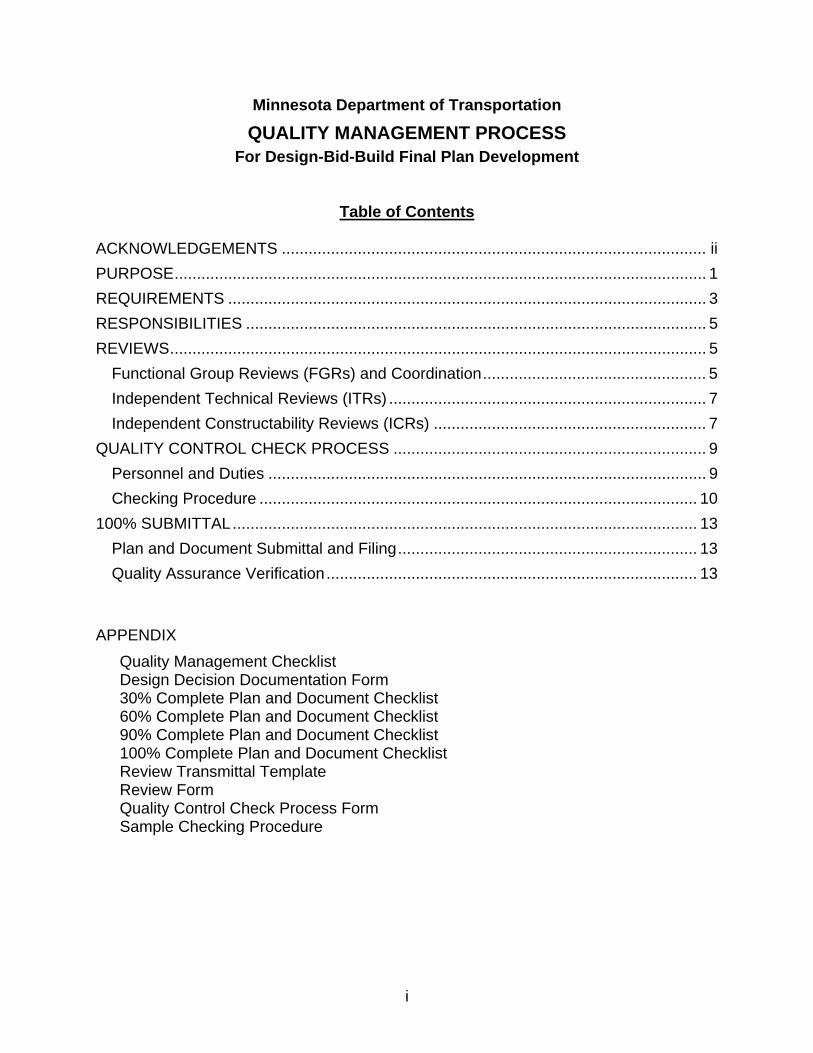
Table of Contents ACKNOWLEDGEMENTS ............................................................................................... ii PURPOSE ....................................................................................................................... 1 REQUIREMENTS ........................................................................................................... 3 RESPONSIBILITIES ....................................................................................................... 5 REVIEWS ........................................................................................................................ 5
Functional Group Reviews (FGRs) and Coordination .................................................. 5 Independent Technical Reviews (ITRs) ....................................................................... 7 Independent Constructability Reviews (ICRs) ............................................................. 7
QUALITY CONTROL CHECK PROCESS ...................................................................... 9 Personnel and Duties .................................................................................................. 9 Checking Procedure .................................................................................................. 10
100% SUBMITTAL ........................................................................................................ 13 Plan and Document Submittal and Filing ................................................................... 13 Quality Assurance Verification ................................................................................... 13
APPENDIX
Quality Management Checklist Design Decision Documentation Form 30% Complete Plan and Document Checklist 60% Complete Plan and Document Checklist 90% Complete Plan and Document Checklist 100% Complete Plan and Document Checklist Review Transmittal Template Review Form Quality Control Check Process Form Sample Checking Procedure
i

Minnesota Department of Transportation QUALITY MANAGEMENT PROCESS
For Design-Bid-Build Final Plan Development
ACKNOWLEDGEMENTS The following teams contributed to the development of this Quality Management Process: Oversight Team: Champion – Jon Chiglo Operations Division – Greg Ous District Engineer – Bob Busch Districts – Nancy Sannes (D1), Jeff Buschette (D4), Mike Kempinger (D6), and
Peter Davich (Metro) PCMG – Todd Broadwell, Craig Collison, and John Griffith OTS – Val Svensson, Tim Swanson, and Darwin Yasis Technical Advisory Team: D1 – Roberta Dwyer, Dan Erickson, Nancy Sannes (Program) and
Pat Huston (Construction) D2 – Phillip Bergem D3 – Todd Grater, Tom Highum, and Rick Beckes (Construction) D4 – Jeff Buschette D6 – Mike Kempinger and Eric Breitsprecher (Construction) D7 – Brett Benzkofer D8 – Paul Jurek and Kelly Brunkhorst (Construction) Metro – Shane Rowbotham and Trudy Elsner (Maintenance) Bridge – Angel Staples Traffic – Bill Pirkl (D2), Mike Schweyen (D6), Mike Gerbensky (Metro), and
Mike Reynolds (Metro) RTMC – Terry Haukom State Aid – Ron Dahlquist Geometrics – Darwin Yasis Site Development – Carol Reamer Landscape Architecture – David Larson CAES – Lou Barrett FHWA – Kevin Kliethermes and Brian Hogge Consultant Team: TKDA – Project Manager – Tim Chalupnik TKDA – Technical Advisor – Kevin Cullen
ii

Minnesota Department of Transportation
QUALITY MANAGEMENT PROCESS For Design-Bid-Build Final Plan Development
PURPOSE The intent of Mn/DOT’s Quality Management Process (QMP) is to assure that a statewide standard of quality is accomplished for the development of final plans on design-bid-build projects. (Similar, yet distinct, processes are used on design-build projects and on projects or portions of projects prepared by or for the Bridge Office). The QMP is based on the philosophy that:
1. Quality will be advocated from the top down and the bottom up.
2. Quality is achieved by adequate planning, scoping, communications and coordination, supervision, and technical direction; by providing adequate time in the schedule for thorough reviews; by proper definition of job requirements and procedures; by the use of appropriately skilled personnel; and by individuals performing their work functions carefully.
3. Implementing quality processes early and throughout the development of
final plans will ultimately save time and help to avoid costly errors and/or scheduling delays.
4. Quality is controlled through documented reviewing and checking
procedures.
5. Quality is assured by having the Central Office Pre-Letting Section coordinate quality assurance verification to determine whether the quality control process and documentation were properly completed.
See the next page for a timeline of the Project Development Process from planning and programming though construction.
1
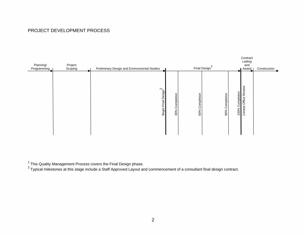
PROJECT DEVELOPMENT PROCESS 1 This Quality Management Process covers the Final Design phase. 2 Typical milestones at this stage include a Staff Approved Layout and commencement of a consultant final design contract.
ContractLetting
and Award
Planning/ Programming
Project Scoping Final Design
1 Preliminary Design and Environmental Studies
Beg
in F
inal
Des
ign2
30%
Com
plet
ion
60%
Com
plet
ion
90%
Com
plet
ion
100%
Com
plet
ion
Cen
tral O
ffice
Rev
iew
Construction
2
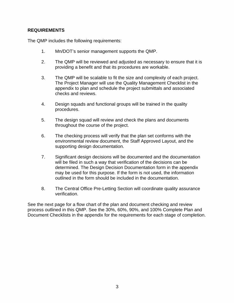
REQUIREMENTS The QMP includes the following requirements:
1. Mn/DOT’s senior management supports the QMP.
2. The QMP will be reviewed and adjusted as necessary to ensure that it is providing a benefit and that its procedures are workable.
3. The QMP will be scalable to fit the size and complexity of each project.
The Project Manager will use the Quality Management Checklist in the appendix to plan and schedule the project submittals and associated checks and reviews.
4. Design squads and functional groups will be trained in the quality
procedures.
5. The design squad will review and check the plans and documents throughout the course of the project.
6. The checking process will verify that the plan set conforms with the
environmental review document, the Staff Approved Layout, and the supporting design documentation.
7. Significant design decisions will be documented and the documentation
will be filed in such a way that verification of the decisions can be determined. The Design Decision Documentation form in the appendix may be used for this purpose. If the form is not used, the information outlined in the form should be included in the documentation.
8. The Central Office Pre-Letting Section will coordinate quality assurance
verification. See the next page for a flow chart of the plan and document checking and review process outlined in this QMP. See the 30%, 60%, 90%, and 100% Complete Plan and Document Checklists in the appendix for the requirements for each stage of completion.
3

PLAN AND DOCUMENT CHECKING AND REVIEW FLOW CHART
100% Quality Control Check Process*
Central Office Quality Assurance Verification
Central Office Review
30% Quality Control Check Process*
Project Approvals and Clearances Advertise for Bids
Functional Group
Reviews**
Independent Technical
Review(s)**
Independent Constructability
Review(s)**
60% Quality Control Check Process*
90% Quality Control Check Process* Final District Review
Consult with the CO Project Delivery
Section on projects with unique features
Functional Group
Reviews**
Independent Technical
Review(s)**
Independent Constructability
Review(s)**
Functional Group
Reviews**
Independent Technical
Review(s)**
Independent Constructability
Review(s)**
100% Submittal to Central Office
Resubmittals as Necessary
Quality Control
Incomplete Quality Control Complete
*The 30%, 60%, and 90% Quality Control Check Processes may be formal or informal. The 100% Quality Control Check Process must be formal. When using the formal process, see the Quality Control Check Process (starting on page 8) and the Sample Checking Procedure in the appendix. **Use the Review Form and the Transmittal Letter Template in the appendix. See the applicable sections of this manual for more information on each review type.
4
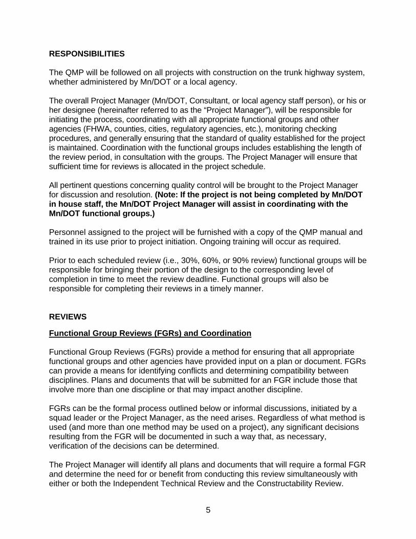
RESPONSIBILITIES The QMP will be followed on all projects with construction on the trunk highway system, whether administered by Mn/DOT or a local agency. The overall Project Manager (Mn/DOT, Consultant, or local agency staff person), or his or her designee (hereinafter referred to as the “Project Manager”), will be responsible for initiating the process, coordinating with all appropriate functional groups and other agencies (FHWA, counties, cities, regulatory agencies, etc.), monitoring checking procedures, and generally ensuring that the standard of quality established for the project is maintained. Coordination with the functional groups includes establishing the length of the review period, in consultation with the groups. The Project Manager will ensure that sufficient time for reviews is allocated in the project schedule. All pertinent questions concerning quality control will be brought to the Project Manager for discussion and resolution. (Note: If the project is not being completed by Mn/DOT in house staff, the Mn/DOT Project Manager will assist in coordinating with the Mn/DOT functional groups.) Personnel assigned to the project will be furnished with a copy of the QMP manual and trained in its use prior to project initiation. Ongoing training will occur as required. Prior to each scheduled review (i.e., 30%, 60%, or 90% review) functional groups will be responsible for bringing their portion of the design to the corresponding level of completion in time to meet the review deadline. Functional groups will also be responsible for completing their reviews in a timely manner. REVIEWS Functional Group Reviews (FGRs) and Coordination Functional Group Reviews (FGRs) provide a method for ensuring that all appropriate functional groups and other agencies have provided input on a plan or document. FGRs can provide a means for identifying conflicts and determining compatibility between disciplines. Plans and documents that will be submitted for an FGR include those that involve more than one discipline or that may impact another discipline. FGRs can be the formal process outlined below or informal discussions, initiated by a squad leader or the Project Manager, as the need arises. Regardless of what method is used (and more than one method may be used on a project), any significant decisions resulting from the FGR will be documented in such a way that, as necessary, verification of the decisions can be determined. The Project Manager will identify all plans and documents that will require a formal FGR and determine the need for or benefit from conducting this review simultaneously with either or both the Independent Technical Review and the Constructability Review.
5
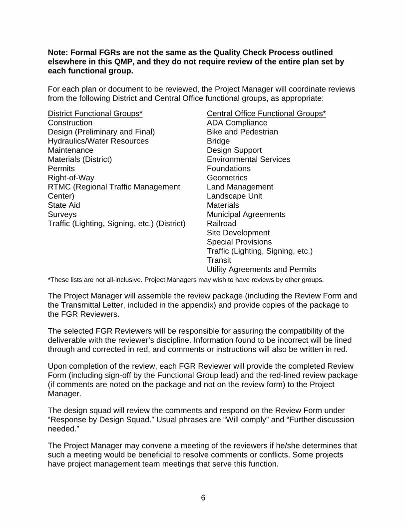
Note: Formal FGRs are not the same as the Quality Check Process outlined elsewhere in this QMP, and they do not require review of the entire plan set by each functional group. For each plan or document to be reviewed, the Project Manager will coordinate reviews from the following District and Central Office functional groups, as appropriate: District Functional Groups* Central Office Functional Groups*
Construction Design (Preliminary and Final) Hydraulics/Water Resources Maintenance Materials (District) Permits Right-of-Way RTMC (Regional Traffic Management Center) State Aid Surveys Traffic (Lighting, Signing, etc.) (District)
ADA Compliance Bike and Pedestrian Bridge Design Support Environmental Services Foundations Geometrics Land Management Landscape Unit Materials Municipal Agreements Railroad Site Development Special Provisions Traffic (Lighting, Signing, etc.) Transit Utility Agreements and Permits
*These lists are not all-inclusive. Project Managers may wish to have reviews by other groups. The Project Manager will assemble the review package (including the Review Form and the Transmittal Letter, included in the appendix) and provide copies of the package to the FGR Reviewers. The selected FGR Reviewers will be responsible for assuring the compatibility of the deliverable with the reviewer’s discipline. Information found to be incorrect will be lined through and corrected in red, and comments or instructions will also be written in red. Upon completion of the review, each FGR Reviewer will provide the completed Review Form (including sign-off by the Functional Group lead) and the red-lined review package (if comments are noted on the package and not on the review form) to the Project Manager. The design squad will review the comments and respond on the Review Form under “Response by Design Squad.” Usual phrases are “Will comply” and “Further discussion needed.” The Project Manager may convene a meeting of the reviewers if he/she determines that such a meeting would be beneficial to resolve comments or conflicts. Some projects have project management team meetings that serve this function.
6

After the needed discussion has occurred, the design squad will update the responses as necessary. When the Functional Group Lead concurs with all of the actions taken, he/she will sign-off on the Review Form. Independent Technical Reviews (ITRs) Independent Technical Reviews (ITRs) are an opportunity to obtain input from an independent expert who is not otherwise involved in the project and can therefore bring a fresh set of eyes to the review of a plan or document. ITRs can occur at any time in the plan development process. ITRs are intended for specific project elements of a complex or unique nature. The Project Manager will identify all plans and documents that will require an ITR and determine the need for or benefit from conducting this review simultaneously with either or both the Functional Group Review and the Constructability Review. The Project Manager may contact other Districts and/or Functional Group Leads for identifying resources for ITRs. For each plan or document to be reviewed, the Project Manager will select the ITR Reviewer, assemble the review package (including the Review Form and the Transmittal Letter, included in the appendix) and provide the package to the ITR Reviewer. The ITR Reviewer will review the plan or document for intent, technical adequacy, and conformance to any applicable standards and format with regard to those aspects of the design he/she has reviewed. The reviewing activity will be recorded directly on the review package. Information found to be incorrect will be lined through and corrected in red, and comments or instructions will also be written in red. Upon completion of the review, the ITR Reviewer will provide the completed Review Form and the red-lined review package (if comments are noted on the package and not on the review form) to the Project Manager. The design squad will review the comments and respond on the Review Form under “Response by Design Squad.” Usual phrases are “Will comply” and “Further discussion needed.” The Project Manager will collect and resolve comments resulting from the ITR and make sure the comments are addressed. Independent Constructability Reviews (ICRs) Independent Constructability Reviews (ICRs) are conducted to obtain input so that construction-related expertise is incorporated into complex or unique designs. This may include reviews by Mn/DOT staff or by a contractor or consultant. (Note: If a contractor or consultant is considered to provide input, care must be given to ensure that a prospective bidder is not given an unfair advantage. Coordination with the Offices of Construction and Innovative Contracting must also occur.)
7
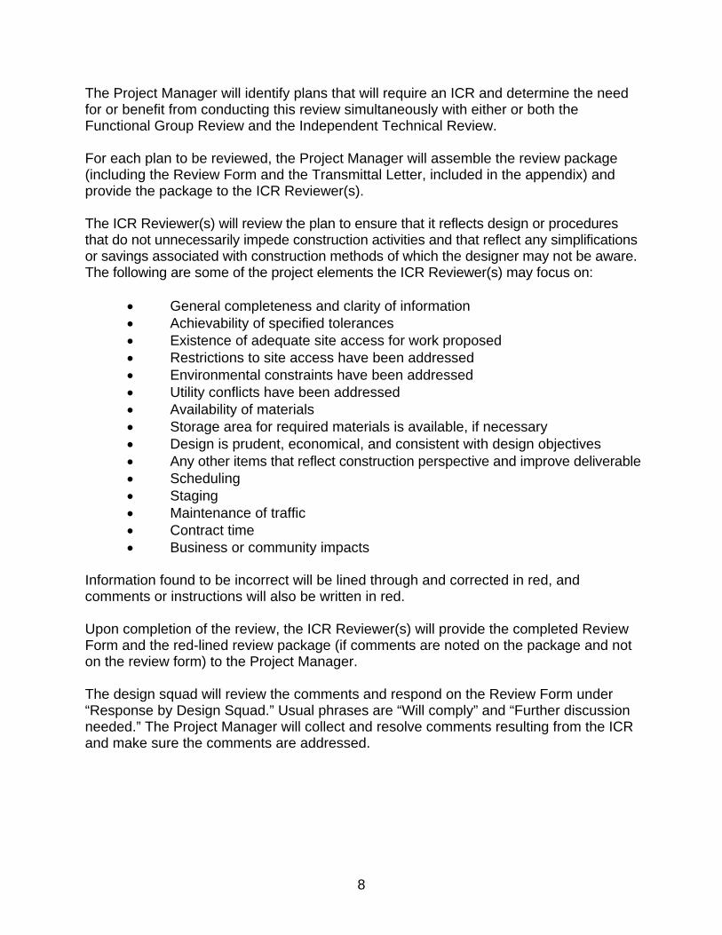
The Project Manager will identify plans that will require an ICR and determine the need for or benefit from conducting this review simultaneously with either or both the Functional Group Review and the Independent Technical Review. For each plan to be reviewed, the Project Manager will assemble the review package (including the Review Form and the Transmittal Letter, included in the appendix) and provide the package to the ICR Reviewer(s). The ICR Reviewer(s) will review the plan to ensure that it reflects design or procedures that do not unnecessarily impede construction activities and that reflect any simplifications or savings associated with construction methods of which the designer may not be aware. The following are some of the project elements the ICR Reviewer(s) may focus on:
• General completeness and clarity of information • Achievability of specified tolerances • Existence of adequate site access for work proposed • Restrictions to site access have been addressed • Environmental constraints have been addressed • Utility conflicts have been addressed • Availability of materials • Storage area for required materials is available, if necessary • Design is prudent, economical, and consistent with design objectives • Any other items that reflect construction perspective and improve deliverable • Scheduling • Staging • Maintenance of traffic • Contract time • Business or community impacts
Information found to be incorrect will be lined through and corrected in red, and comments or instructions will also be written in red. Upon completion of the review, the ICR Reviewer(s) will provide the completed Review Form and the red-lined review package (if comments are noted on the package and not on the review form) to the Project Manager. The design squad will review the comments and respond on the Review Form under “Response by Design Squad.” Usual phrases are “Will comply” and “Further discussion needed.” The Project Manager will collect and resolve comments resulting from the ICR and make sure the comments are addressed.
8
QUALITY CONTROL CHECK PROCESS The primary goals of this process are to provide a technical review of project plans and documents by a qualified staff member, to allow the designer or author/collator of the plan or document and the reviewer to come to a consensus on any changes, and to make certain any needed changes are made correctly. The Quality Control Check Process may be the formal process described below or an informal process determined by the Project Manager. The formal process must be used at 100% completion (prior to submittal to the Central Office) and may be used at the 30%, 60%, and 90% stages of completion. It is recommended that the formal process be used more often on complex projects. Documentation of formal and informal checking processes shall be kept in the project file until the Contract is awarded. The core of the formal Quality Control Check Process involves checking, correcting, and verifying that the corrections have been made. Back checking, as outlined below, is not required until the check at 100%. The following plans and documents will be subject to this checking process:
• Construction plans • Special provisions • Design and quantity calculations • A design document (for example, design exceptions, design memos,
Public Interest Findings) • A cost estimate • A schedule
Personnel and Duties Originator: The Originator will usually be the designer or author/collator of the plan or document. The Originator will have the primary responsibility for accuracy and adequacy. In most cases, the Originator will also function as the Back Checker. Checker: The Checker will be responsible for checking the plan or document independently of the Originator (the Checker must not have prepared the item being checked). In most cases, the Checker will also function as the Verifier.
For plans, calculations, specifications, special provisions, and design documents, the Checker will be a qualified person with sufficient knowledge and experience in the discipline of the work being checked.
9

For structural design plans and calculations, the Checker will be a licensed Professional Engineer, as appropriate, with sufficient knowledge and experience to understand the analysis and design components of the project; the use of standards; and the requirements, constraints, and limitations of incorporating the standards in the project.
For computer program input, the Checker will be skilled in the use of the design software being used.
Back Checker: The Back Checker (usually the Originator) will be responsible for confirming/denying corrections asserted by the Checker. In cases where no corrections, additions, or deletions were found, there will be no need for back checking. Back checking may be used but is not required until the check at 100%. Corrector: Correction of the plan or document will be completed by the Corrector, who may be the Originator, or a CADD technician, administrative assistant, or other personnel (as appropriate). Verifier: The Verifier (usually the Checker) will be responsible for confirming that corrections have been accurately made. Central Office: The Central Office Pre-Letting Section will coordinate the Quality Assurance verification. Checking Procedure See the Sample Checking Procedure in the appendix for an example of the mark-ups outlined in the following procedure. 1. The Originator will prepare the Check Print. See page 9 for a list of plans and
documents that could constitute a “Check Print.”
On the Check Print, the Originator will make sure that all plan sheets are appropriately numbered or that the pages of all other documents, including calculations, are sequentially numbered.
The Originator will fill out the top of the Quality Control Check Process Form (included in the appendix). The form will be attached to the Check Print. The Originator will sign and date the Quality Control Check Process Form and provide the Check Print to the Checker.
10
2. The Checker will check the plan or document and record the checking activity on the Check Print.
Information found to be correct will be highlighted in yellow.* The checker may choose to use yellow marks or yellow checkmarks rather than highlighting the information. No matter what type of marking style is used, the markings must clearly show that the checking occurred.
Information found to be incorrect will be lined through and corrected in red, and comments or instructions will also be written in red.
For calculations, the Checker will thoroughly check the calculations including assumptions, mandated parameters, references, given values, and formulas; check for omissions and accuracy of arithmetic; ask questions of the designer in areas that are not clear or where additional calculations are required; seek technical advice if unsure of any particular element of the calculation; and review the output data of computer calculations for consistency with expected results.
For computer program input and output, the Checker will thoroughly check the input parameters and all assumptions, references, and mandated values. In the case of GEOPAK output, the Checker will thoroughly check the output and associated reports, as well as measure or visually verify the CADD files to ensure that desirable results have been attained and that design standards or required criteria have been met. In the case of non-GEOPAK related output, the Checker will thoroughly check graphical output by measuring or visually verifying to ensure that the desired results have been achieved.
For plans, the Checker will use the appropriate plan review checklists. The following is a list of checklists that could be utilized:
Road Design Plans Final Checklist (Design Scene, Chapter 18) http://www.dot.state.mn.us/pre-letting/scene/download/ scene-complete.pdf#chapter-18
30%, 60%, and 90% Plan Review Checklists (Metro District Final Design) http://www.dot.state.mn.us/metro/finaldesign/docs.html
Traffic Signal Design Checklists (Signal Design Manual) http://www.dot.state.mn.us/trafficeng/publ/signaldesign/ 2010%20Signal%20Design%20Manual/2010_Signal_Design_Manual.pdf
The Checker will check the entire drawing for design intent, technical adequacy, and conformance to any applicable standards and format. The Checker will be responsible for determining that the drawing is consistent with the corresponding calculations and for affirming that those calculations have been properly
* The colors specified in this Quality Control Check Process are recommended; however, Districts can choose their own colors, provided that the various steps in the checking process can be distinguished on the Check Print.
11

checked. The Checker will also check to ensure that all relevant design documents have been incorporated.
For specifications and special provisions, the Checker will review the document for applicability and clarity. The Checker will review the entire document, even if only a small portion has changed, to ensure that revisions have not introduced conflict or ambiguities. The Checker will also review the special provisions together with the plans to ensure that all necessary pay items have been covered, that the pay item units are correct, and that the plans and special provisions are consistent. The Checker will also check to ensure that all relevant design documents have been incorporated.
For design documents, each Checker will place their initials next to their comments or corrections (this is not necessary if using Track Changes in Word, which automatically records this information). Checkers will review the document with regard to their responsible area, conformance with project criteria and requirements, and content. They will also review those parts of the document that interface with their area of responsibility to assure that there are no conflicts. The editorial reviewer will be responsible for assuring uniform format, proper sentence structure, proper syntax, and spelling.
Note: For checking related to non-standard structures, refer to the Bridge Office Quality Manual. Non-standard structures include those with any deviation from the Standard Plans.
Following the checking, the Checker(s) will sign and date the Quality Control Check Process Form and provide the Check Print and the form to the Back Checker.
3. The Back Checker will review each of the Checker’s corrections (red marks) and
will record the back-checking activity on the Check Print.
If the Back Checker is in agreement with a correction, the Back Checker will place a check mark in green next to the correction.
If the Back Checker finds any additional changes not picked up by the Checker, the Back Checker will confer with the Checker and, with the concurrence of the Checker, will add the additional changes in green.
If the Back Checker is not in agreement with a Checker’s correction, the Back Checker will confer with the Checker. If both agree that the Checker’s correction should not be made, the Back Checker will cross out the Checker’s correction in green. The Back Checker must not obliterate the Checker’s marks. If the Back Checker and Checker cannot achieve resolution, the Project Manager will be consulted to resolve the differences.
Following the back checking, the Back Checker will sign and date the Quality Control Check Process Form and provide the Check Print and the form to the Corrector.
12
13
4. The Corrector will make the changes to the plan or document and will highlight or circle in blue each correction as incorporated.
When all of the corrections have been made, the Corrector will sign and date the Quality Control Check Process Form. A new copy of the corrected plan or document and the marked-up Check Print will be provided to the Verifier.
5. The Verifier will compare the new copy of the plan or document with the Check
Print to confirm that the agreed-to corrections have been incorporated without error.
If a correction has been properly made on the new copy, the Verifier will cross-highlight in yellow the blue circle or highlight on the Check Print.
If a correction has not been made or is in error, the new copy of the plan or document will be annotated in red and returned to the Corrector. The Corrector will make the corrections as outlined above and provide a new copy of the plan or document to the Verifier.
Once all corrections have been properly made and verified, the Verifier will sign and date the Quality Control Check Process Form.
100% SUBMITTAL Plan and Document Submittal and Filing When all project plans and documents have been checked, the Project Manager will file the Quality Control Check Process Form for each item in ProjectWise and submit the plans, special provisions, and cost estimate to the Central Office. (If desired, the District may perform quality assurance verification prior to submittal to the Central Office.) The Check Print for each item (hard or electronic copy) shall be kept by the Project Manager until the construction contract is awarded. Quality Assurance Verification The Central Office Project Delivery Section will review the Quality Control Check Process Forms to determine whether or not the quality control procedures described in steps 1-5, above, were implemented. In certain circumstances, the Central Office reviewer may also review the Check Prints at the Project Manager’s office. The reviewer will coordinate with the Project Manager (or others as appropriate) to resolve all issues arising from the quality assurance verification. Once the verification is complete and any nonconformance issues have been resolved, the reviewer will sign and date the Quality Control Check Process Form. The completed form will be filed in ProjectWise.

APPENDIX

4/19/12
QUALITY MANAGEMENT CHECKLIST (To be completed by the Project Manager at the beginning of Final Design
and updated throughout the project)
Project Manager:
Design Squad:
State Project No.:
Project Description:
Programmed Letting Date: Checking* and Reviews at: 30% Complete: Planned
Date** Completed
Date** Not
Needed (A detailed explanation is required if Not Needed is checked.***)
Indicate which reviews are planned below.
Needed Not Needed (A detailed explanation is required if Not Needed is checked.***) FGR ITR ICR 60% Complete: Planned
Date** Completed
Date** Not
Needed (A detailed explanation is required if Not Needed is checked.***)
Indicate which reviews are planned below.
Needed Not Needed (A detailed explanation is required if Not Needed is checked.***) FGR ITR ICR 90% Complete: Planned
Date** Completed
Date**
Indicate which reviews are planned below.
Needed Not Needed (A detailed explanation is required if Not Needed is checked.***) FGR ITR ICR 100% Complete: Planned
Date** Completed
Date**
* Formal or informal at 30%, 60%, and 90%. Formal at 100%. ** The date plans and documents are completed, checked, and ready for review. *** N/A or equivalent is not acceptable.
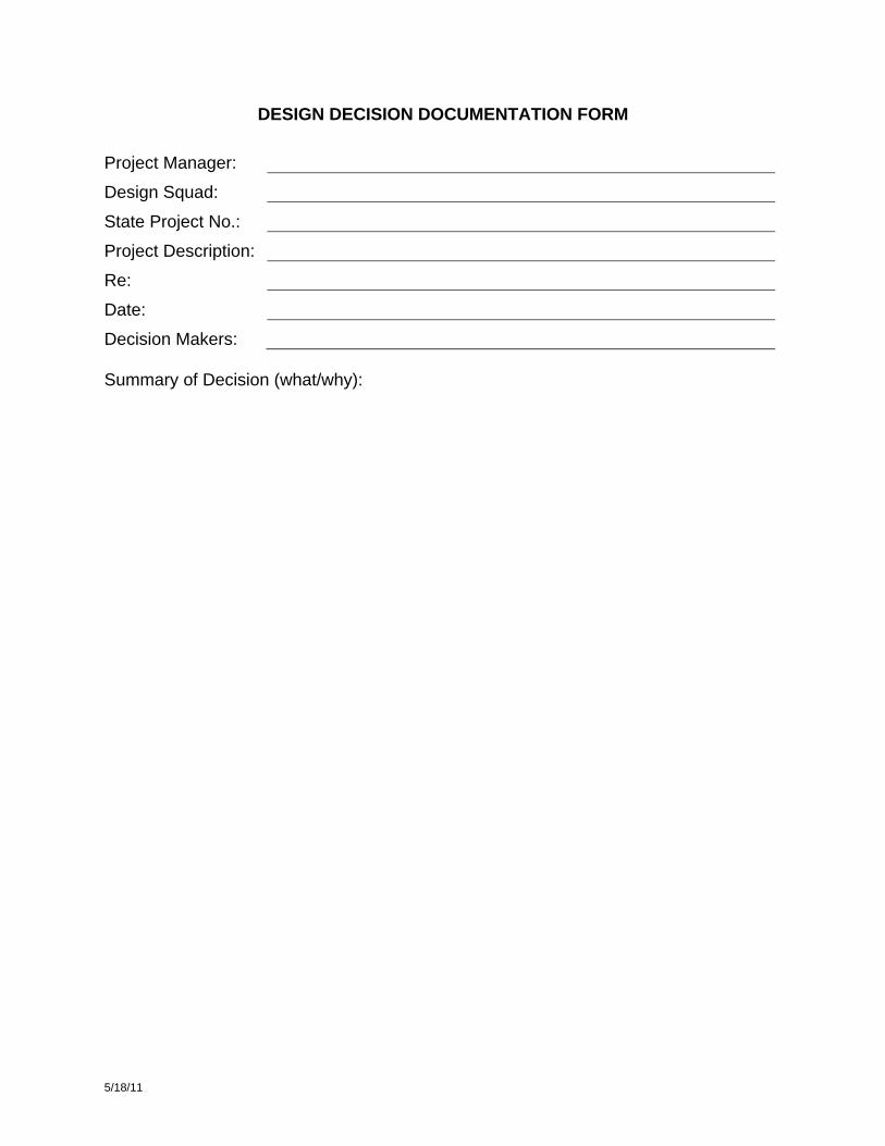
DESIGN DECISION DOCUMENTATION FORM Project Manager:
Design Squad:
State Project No.:
Project Description:
Re:
Date:
Decision Makers: Summary of Decision (what/why):
5/18/11
4/19/12
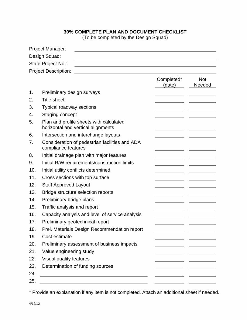
30% COMPLETE PLAN AND DOCUMENT CHECKLIST (To be completed by the Design Squad)
Project Manager: Design Squad: State Project No.: Project Description:
Completed*
(date) Not
Needed 1. Preliminary design surveys 2. Title sheet 3. Typical roadway sections 4. Staging concept 5. Plan and profile sheets with calculated
horizontal and vertical alignments
6. Intersection and interchange layouts 7. Consideration of pedestrian facilities and ADA
compliance features
8. Initial drainage plan with major features 9. Initial R/W requirements/construction limits 10. Initial utility conflicts determined 11. Cross sections with top surface 12. Staff Approved Layout 13. Bridge structure selection reports 14. Preliminary bridge plans 15. Traffic analysis and report 16. Capacity analysis and level of service analysis 17. Preliminary geotechnical report 18. Prel. Materials Design Recommendation report 19. Cost estimate 20. Preliminary assessment of business impacts 21. Value engineering study 22. Visual quality features 23. Determination of funding sources 24. 25. * Provide an explanation if any item is not completed. Attach an additional sheet if needed.
4/19/12
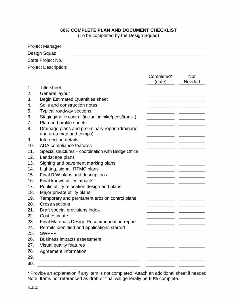
60% COMPLETE PLAN AND DOCUMENT CHECKLIST (To be completed by the Design Squad)
Project Manager: Design Squad: State Project No.: Project Description:
Completed* (date)
Not Needed
1. Title sheet 2. General layout 3. Begin Estimated Quantities sheet 4. Soils and construction notes 5. Typical roadway sections 6. Staging/traffic control (including bike/peds/transit) 7. Plan and profile sheets 8. Drainage plans and preliminary report (drainage
and area map and comps)
9. Intersection details 10. ADA compliance features 11. Special structures – coordination with Bridge Office 12. Landscape plans 13. Signing and pavement marking plans 14. Lighting, signal, RTMC plans 15. Final R/W plans and descriptions 16. Final known utility impacts 17. Public utility relocation design and plans 18. Major private utility plans 19. Temporary and permanent erosion control plans 20. Cross sections 21. Draft special provisions index 22. Cost estimate 23. Final Materials Design Recommendation report 24. Permits identified and applications started 25. SWPPP 26. Business impacts assessment 27. Visual quality features 28. Agreement information 29. 30. * Provide an explanation if any item is not completed. Attach an additional sheet if needed. Note: Items not referenced as draft or final will generally be 60% complete.
4/19/12
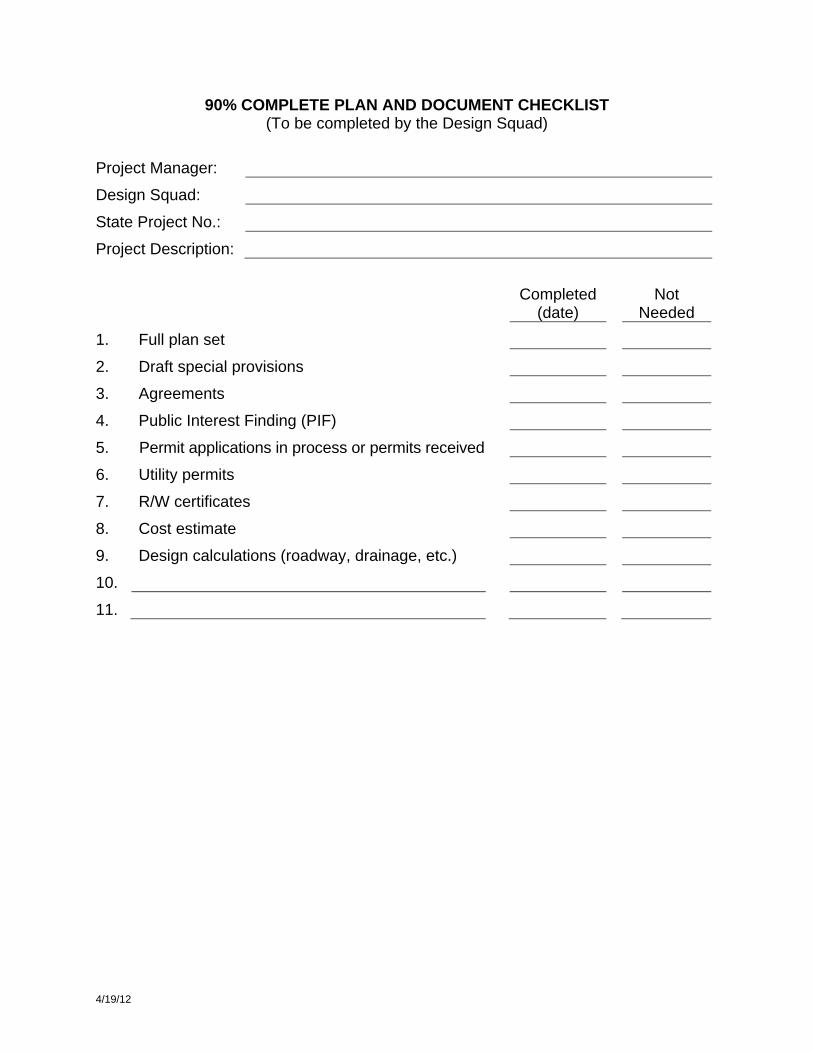
90% COMPLETE PLAN AND DOCUMENT CHECKLIST (To be completed by the Design Squad)
Project Manager:
Design Squad:
State Project No.:
Project Description:
Completed
(date) Not
Needed
1. Full plan set
2. Draft special provisions
3. Agreements
4. Public Interest Finding (PIF)
5. Permit applications in process or permits received
6. Utility permits
7. R/W certificates
8. Cost estimate
9. Design calculations (roadway, drainage, etc.)
10.
11.

5/18/11
100% COMPLETE PLAN AND DOCUMENT CHECKLIST (To be completed by the Design Squad)
Project Manager:
Design Squad:
State Project No.:
Project Description:
Completed
(date) Not
Needed
1. Submittal letter
2. Certified originals
3. Final special provisions
4. Final designer construction cost estimate
5. Environmental permits
6.
7.

STATE OF MINNESOTA DEPARTMENT OF TRANSPORTATION
Office Memorandum
DATE: __________ TO: Addressees FROM: __________ SUBJECT: SP __________
Funding: __________ FGR/ITR/ICR Review
Attached for your review and comment are __________ for the above referenced project. The letting date for this project is __________. The construction starting date will be __________. There will be __________ working days allowed. Intermediate Completion of Project (Open to Traffic) will be __________. Project completion will be __________. The Programmed estimate is $__________. The current District construction cost estimate is $__________. The total project cost estimate is $__________. Please use the attached Review Form for your comments. Make your comments clear and self-explanatory. Attach examples if they will make your comments clearer. Make additional copies of the form if required. If you have questions, please call me to discuss them. The _________ is a critical element of the project, so comments relating to _________ would be appreciated. Please return the Review Form (even if you have no comments) and your comments to me no later than _________. This is the final date for comments. The following letters after your functional group represent the portions of the plan package you are receiving: (P) = plan, (X) = cross sections, (S) = special provisions. Addressees: Construction, ___ Right-of-Way, ___ Design (Preliminary and Final), ___ RTMC (Regional Traffic Mgmt. Ctr.), ___ Hydraulics/Water Resources, ___ State Aid, ___ Maintenance, ___ Surveys, ___ Materials (District), ___ Traffic (Lighting, Signing, etc.), ___ Permits, ___ __________, ___

4/19/12 Page ___ of ___
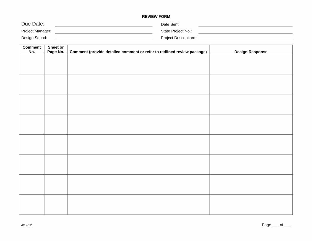
REVIEW FORM
Due Date: Date Sent:
Project Manager: State Project No.:
Design Squad: Project Description: Review Phase: Review Type: Functional Groups:
30% FGR (Functional Group Review) ADA Compliance Right-of-Way 60% ITR (Independent Technical Construction RTMC (Regional Traffic Mgmt. Ctr.) 90% Review) Design (Preliminary and Final) State Aid ICR (Independent Constructability Hydraulics/Water Resources Surveys
(specify) Review) Maintenance Traffic (Lighting, Signing, etc.) Materials (District) (project element) Permits Comments By: Name: Phone: Date:
*Functional Group Lead Concurs With Comments (below): Name: Signature: Date:
*Functional Group Lead Concurs With Design Response (below): Name: Signature: Date:
* For FGRs only.
Comment No.
Sheet or Page No. Comment (provide detailed comment or refer to redlined review package) Design Response
4/19/12 Page ___ of ___
REVIEW FORM
Due Date: Date Sent:
Project Manager: State Project No.:
Design Squad: Project Description: Comment
No. Sheet or Page No. Comment (provide detailed comment or refer to redlined review package) Design Response

4/19/12
QUALITY CONTROL CHECK PROCESS FORM
Project Manager:
Design Squad:
State Project No.:
Project Description:
Item to be Checked:
Originated by:
Print name Sign Date
Checked by:
Print name Sign Date
Back Checked by:
Print name Sign Date
Corrected by:
Print name Sign Date
Verified by:
Print name Sign Date
Quality Assurance Verification by Central Office Project Delivery Section:
Print name Sign Date

15
40’ R.
12’
12’
10’
8’
12’
12’
10’
14’
STA. 14+85
BEGIN TAPER
STA. 15+45
END TAPER
15:1
ORIGINATOR{ MAIN ST.
CHECK PRINT
15
40’ R.
12’
12’
10’
8’
12’
12’
10’
14’
STA. 14+85
BEGIN TAPER
STA. 15+45
END TAPER
15:1
{ MAIN ST.
CHECK PRINT
CHECK PRINT
CORRECTOR
15
40’ R.
12’
12’
10’
12’
12’
10’
14’
STA. 14+85
BEGIN TAPER
STA. 15+45
END TAPER
1:15
{ MAIN ST.
CORRECTED PLAN SHEET
CHECKER
BACKCHECKER
VERIFIER
CONSTRUCTION LIMITS
SHOW AND LABEL
10’
1:15
40’ R
.
40’ R
. CONSTRUCTION LIMITS
SHOW AND LABEL
1:15
10’
40’ R
. CONSTRUCTION LIMITS
SHOW AND LABEL
1:15
10’
40’ R
. CONSTRUCTION LIMITS
SHOW AND LABEL
1:15
10’
15
40’ R.
12’
12’
10’
8’
12’
12’
10’
14’
STA. 14+85
BEGIN TAPER
STA. 15+45
END TAPER
15:1
{ MAIN ST.
CHECK PRINT
10’
1:15
40’ R
.
40’ R
.
1:15
10’
40’ R
.
1:15
10’
40’ R
.
1:15
10’
B624 C&G
B624 C&G
B424B424B424B424
CONSTRUCTION LIMITS
SHOW AND LABEL
CONSTRUCTION LIMITS
SHOW AND LABEL
CONSTRUCTION LIMITS
SHOW AND LABEL
CONSTRUCTION LIMITS
SHOW AND LABELB624 C&G
B424B424B424B424
DECISION IS MARKED BY BOTH.DISCUSS AND RESOLVE DIFFERENCE.BACKCHECKER AND CHECKER
15
40’ R.
12’
12’
10’
8’
12’
12’
10’
14’
STA. 14+85
BEGIN TAPER
STA. 15+45
END TAPER
15:1
{ MAIN ST.
10’
1:15
40’ R
.
40’ R
.
1:15
10’
40’ R
.
1:15
10’
40’ R
.
1:15
10’
CONSTRUCTION LIMITS
SHOW AND LABEL
CONSTRUCTION LIMITS
SHOW AND LABEL
CONSTRUCTION LIMITS
SHOW AND LABEL
CONSTRUCTION LIMITS
SHOW AND LABELB624 C&G
B424B424B424B424
CHECK PRINT
15
40’ R.
12’
12’
10’
8’
12’
12’
10’
14’
STA. 14+85
BEGIN TAPER
STA. 15+45
END TAPER
15:1
{ MAIN ST.
10’
1:15
40’ R
.
40’ R
.
1:15
10’
40’ R
.
1:15
10’
40’ R
.
1:15
10’
CONSTRUCTION LIMITS
SHOW AND LABEL
CONSTRUCTION LIMITS
SHOW AND LABEL
CONSTRUCTION LIMITS
SHOW AND LABEL
CONSTRUCTION LIMITS
SHOW AND LABELB624 C&G
B424B424B424B424
B624 C&G
10’
40’ R.
LIMITS
CONSTRUCTION
LIMITS
CONSTRUCTION
SAMPLE CHECKING PROCEDURE
(Usually the Originator)
(Usually the Checker)
ALL ELEMENTS HAVE BEEN CHECKEDAS NECESSARY TO VERIFY THATCORRECT INFORMATION HIGHLIGHTED
INSTRUCTIONSCORRECTIONS, COMMENTS, AND
YELLOW
RED
GREENWITH CORRECTIONCHECK MARK IF IN AGREEMENT
IN AGREEMENT WITH CORRECTIONSEE EXAMPLE TO THE LEFT IF NOT
BLUEMADECIRCLE OR HIGHLIGHT CORRECTIONS
YELLOWPROPERLY MADECROSS HIGHLIGHT CORRECTIONS
REQUIRED ONLY AT 100%