
Quality inspection guide - eschneider.pl Aparaty nn/Rozdzielnice obudowy... · Quality inspection...
60
Quality inspection guide GIQ2 / ESB / 11.1998 1 Foreword On the strength of its experience, the Groupe Schneider has always sought to produce quality equipment. But what exactly do we mean by Quality. It is: “ the set of properties and characteristics of a product or service which make it suitable to satisfy implicit or explicit needs (NFX 50-120). ” Although final inspection is in some respects a statement of failure (as we have not been able to control the necessary quality throughout the assembly process) it is nevertheless a vital stage in equipment production. This stage must be performed with care and rigour, both with respect to customer specifications (explicit needs), and proper operating procedures (implicit needs), in order to satisfy the customer. This amended quality inspection guide (GIQ2), designed by ESB specially for you, contains all the procedures and instructions extensively inspired by our units in France. This document completes the range of existing guides (technical guides, tool guide) to which we often refer in the various chapters. By adapting it to your own needs, it should ensure that you obtain an equipment production quality of the standard desired by Schneider and able to satisfy the requirements of our customers. We can guarantee the durability of this document by means of regular exchanges. Please contact us at the numbers below. Thank you for your contribution. Jean-Jacques Kuntz Patrick Charles Jean-Pierre Chorda Tél : +33 04 76 39 40 94 Tél : +33 04 76 39 40 70 Tél : +33 04 76 39 40 71 Fax : +33 04 76 39 40 72 Fax : +33 04 76 39 40 72 Fax : +33 04 76 39 40 72
Transcript of Quality inspection guide - eschneider.pl Aparaty nn/Rozdzielnice obudowy... · Quality inspection...

Quality inspection guide
GIQ2 / ESB / 11.1998 1
Foreword On the strength of its experience, the Groupe Schneider has always sought to produce quality equipment. But what exactly do we mean by Quality. It is: “ the set of properties and characteristics of a product or service which make it suitable to satisfy implicit or explicit needs (NFX 50-120). ” Although final inspection is in some respects a statement of failure (as we have not been able to control the necessary quality throughout the assembly process) it is nevertheless a vital stage in equipment production. This stage must be performed with care and rigour, both with respect to customer specifications (explicit needs), and proper operating procedures (implicit needs), in order to satisfy the customer. This amended quality inspection guide (GIQ2), designed by ESB specially for you, contains all the procedures and instructions extensively inspired by our units in France. This document completes the range of existing guides (technical guides, tool guide) to which we often refer in the various chapters. By adapting it to your own needs, it should ensure that you obtain an equipment production quality of the standard desired by Schneider and able to satisfy the requirements of our customers. We can guarantee the durability of this document by means of regular exchanges. Please contact us at the numbers below. Thank you for your contribution.
Jean-Jacques Kuntz Patrick Charles Jean-Pierre Chorda Tél : +33 04 76 39 40 94 Tél : +33 04 76 39 40 70 Tél : +33 04 76 39 40 71 Fax : +33 04 76 39 40 72 Fax : +33 04 76 39 40 72 Fax : +33 04 76 39 40 72

Contents
GIQ2 / ESB / 11.1998 2
Inspection Qualité : moyens et procédures
1. Justification of quality inspection 4
2. Quality inspection 6
2.1. Quality inspection function 6
2.2. Quality inspection responsibility 6
2.3. Quality inspector’s profile 6
2.4. Quality inspection zone 6
2.5. Necessary documents 6
2.6. Dedicated material means 6
2.7. Necessary human resources 7
3. Continuous inspection 7
4. Final inspection 8
5. Summarising operations after final inspection 11
5.1. Project without customer acceptance or missing parts 12
5.2. Project without customer acceptance but with missing parts 12
5.3. Project with customer acceptance but without missing parts 12
5.4. Project with customer acceptance and missing parts 13
Quality inspection: instructions
6. Performing in-process inspection 15
6.1. Reminderl 15
6.2. Composition 15
7. Performing the final inspection 15
7.1. Conformity check 15
7.1.1. Enclosure 15 7.1.2. Framework 16 7.1.3. Switchgear 17 7.1.4. Busbars 19 7.1.5. PE and/or PEN protection busbars 20 7.1.6. Flexible busbars 21 7.1.7. Cables 21 7.1.8. Connections 22
7.2. Mechanical checks 23

Contents
GIQ2 / ESB / 11.1998 3
7.3. Electrical checks 24
7.3.1. Operating tests 24 7.3.2. Dielectric withstand (Standard IEC 439.1 paragraph 8.3.2) 26 7.3.3. Insulation resistance 28 7.3.4. Electrical continuity of the protection circuits (standard IEC 439.1 paragraph 8.3.3) 29
Appendix
8. Quality indicator chart 31
8.1. Purpose 31
8.2. Principles 31
8.3. Scope 31
8.4. Produced non quality 32
8.5. Example of a Produced Non Quality index switchboard 33
8.6. Example of a graph showing the non quality index 33
9. Control of inspection means 34
9.1. Purpose 34
9.2. Reminders of basic principles 34
9.3. Responsibility 34
9.4. General diagram of operations 35
9.5. Application rules 35
9.5.1. Choice of means 35 9.5.2. Classification of means 35 9.5.3. Checking frequency 36 9.5.4. Listing and monitoring the inspection means 36 9.5.5. Occasional checks 36 9.5.6. Devices outside the accuracy class 36
10. List of equipment 38
10.1. The Quality Inspector’s tools 38
10.2. Switchgear common to the Quality Inspection 38
11. Example of measuring means accuracy 39
12. Useful addresses 40
13. File example 40
13.1. List of checking procedures 40
13.2. Example of Quality Inspection documents 45
14. Glossary 60

Quality inspection: means and procedures
GIQ2 / ESB / 11.1998 4
Procedure “ Set of organisational rules of an administrative nature in order to achieve a certain result (see Petit Robert dictionary) “ Specified way of accomplishing an activity ” (see ISO 9001)
1. Justification of quality inspection The complexity of LV equipment and the large number of human interventions and thus risk of errors, are the main reasons for its implementation. It is also stipulated in the standards (see I.E.C. 439.1) which defines three routine tests (or individual tests) to complete the type tests: n giving the equipment the TTA label (Type Tested Assembly), n and which are binding on the panel builder’s responsibility. These three individual tests are: n Electrical operation, n Dielectric tests and/or measurement of insulation resistance, n Checking of the electrical continuity of the protective circuit.
Quality inspection: means and procedures
GIQ2 / ESB / 11.1998 5
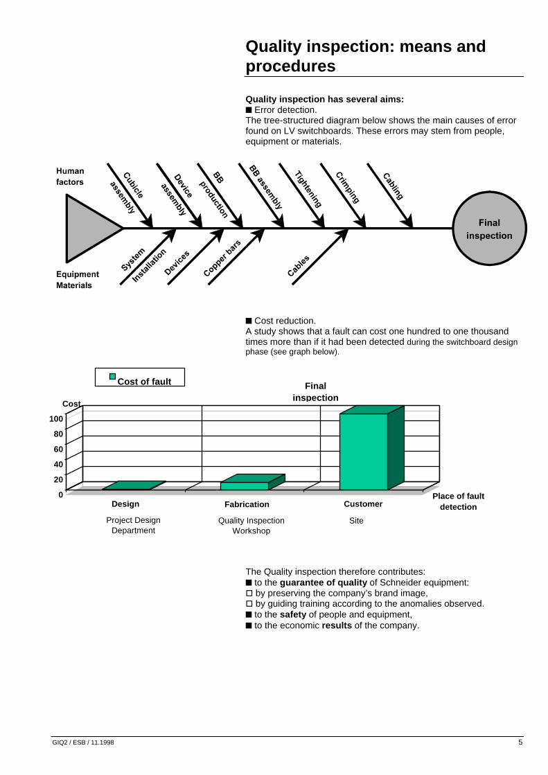
Quality inspection has several aims: n Error detection. The tree-structured diagram below shows the main causes of error found on LV switchboards. These errors may stem from people, equipment or materials.
n Cost reduction. A study shows that a fault can cost one hundred to one thousand times more than if it had been detected during the switchboard design phase (see graph below). The Quality inspection therefore contributes: n to the guarantee of quality of Schneider equipment: o by preserving the company’s brand image, o by guiding training according to the anomalies observed. n to the safety of people and equipment, n to the economic results of the company.
Fabrication0
20
40
60
80
100
Design CustomerPlace of fault
detection
Cost of fault Final inspection
Project Design Department
Quality Inspection Workshop
Site
Cost
Quality inspection: means and procedures
GIQ2 / ESB / 11.1998 6
2. Quality inspection
2.1. Quality inspection function o Perform the inspection with respect to: – the project file and the customer document, – Schneider rules and products, – IEC standards. o Carry out acceptance tests in the customers’ presence. o Perform quality follow-up and corrective actions.
2.2. Quality inspection responsibility Quality inspection: o is directly attached to management and independent from manufacture, o can delay delivery of a project and require reworking to ensure conformity, o performs the corrective actions, o in event of a dispute, informs the unit manager who alone has the power to decide, o is responsible for the safety of all people working in the quality inspection zone.
2.3. Quality inspector’s profile o Electrotechnical training (B.T.S. or equivalent: higher technician’s certificate), o Versatile, o Sound knowledge of Schneider equipment, o Authorised to work near electrical current: – Knowledge of the hazards of electrical current, – Authorisation by approved training course, – Basic notions of first-aid.
2.4. Quality inspection zone o is independent from production, o must be physically separated from the other departments: – for reasons linked to the hazards of electrical current, – for protection of people and equipment, o is clearly marked out (tapes, partitions, etc.) o is clearly indicated (warning beacon, flashing light, etc.)
2.5. Necessary documents To carry out the various checks, the quality inspector must possess a complete, updated file of the project and the customer technical specifications.
2.6. Dedicated material means The quality inspector must: o Have the necessary inspection means (mechanical and electrical): – Test desk, variable current and voltage sources, – Inspector, peak demand, – Dielectrometer, insulation monitor, – Tools, – Mounting plates, – Associated documents. o Ensure periodical calibration of his equipment.
Quality inspection: means and procedures
GIQ2 / ESB / 11.1998 7
2.7. Necessary human resources In the Groupe’s equipment units, the quality inspectors account for approximately 10% of workforce, i.e. 1 quality inspector for 8 to 10 cablers/fitters.
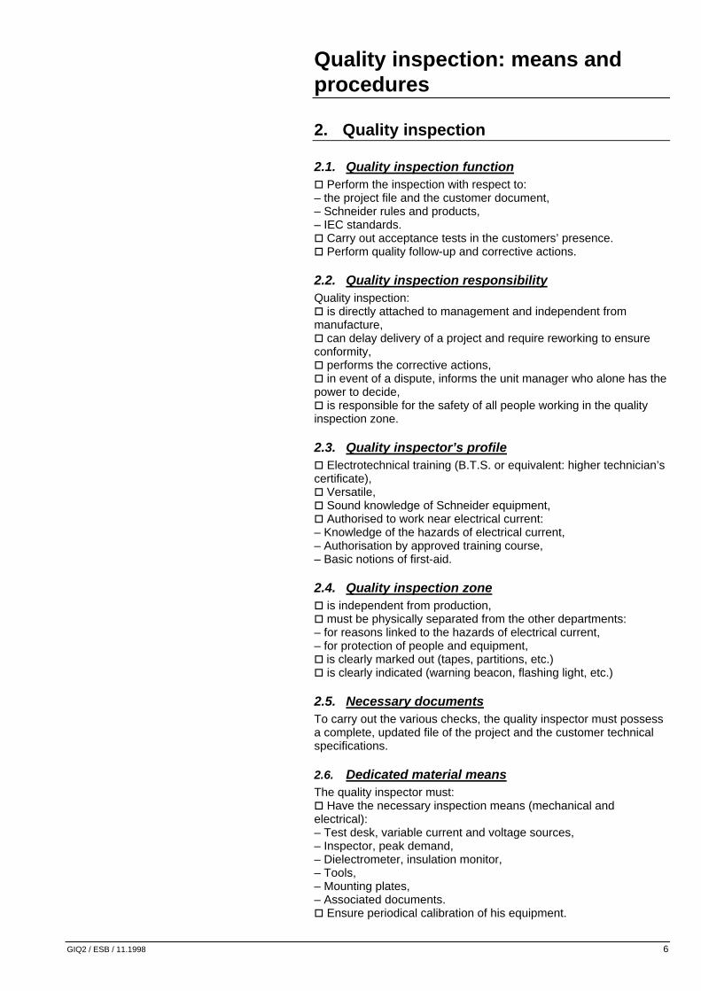
3. Continuous inspection n Continuous inspection consists of carrying out checks throughout manufacture in the form of: o Operator checks which make each operator responsible for the quality of his work. The instructions provided at each manufacturing stage enable these checks to be formally defined (see ISO 9000). o Systematic inspection or sampling which is part of quality inspection and takes place during manufacture. n A follow-up sheet must be used to log the status of the inspections performed. n The various inspections can be modelled by the diagram below: This diagram represents the operations on which in-process inspections are carried out. The many phases in which operator inspections and incoming quality inspection are performed are clearly marked.
NB: Despite the operator checks performed for each operation, final inspection is always necessary. It can be reduced but never completely removed, particularly as it is stipulated by standard IEC 439.1.

Quality inspection: means and procedures
GIQ2 / ESB / 11.1998 8
4. Final inspection Final inspection guarantees operation and conformity of products with respect to applicable drawings and standards. It is performed by the unit’s Q.I. department. A document per project formulating the customer’s requirements and transcribing the specification is used for the checking phases during assembly and for final inspection. It forms the first reference document (project file). n The final inspection takes place as follows: o Carry out the conformity check, o Conduct the tests, o Modify the Project Design file by adding any necessary annotations (throughout testing), o List all the nonconformities: – by drafting a list of missing parts, – by noting all the faults observed. o Draft the report, o Ensure reworking for conformity, o If customer acceptance is scheduled, receive the customer and his representative in the quality inspection zone. Carry out the tests and ask him to sign the report at the end of customer acceptance, o Point out any areas of dispute between customer and supplier, o Ensure that the Project Design documents have been properly updated, by checking final version status and dating the versions, o Sign the documents and in particular the report o Archive the final inspection documents. n List of the various final inspection tests: a. conformity checks: o Enclosure, – Appearance, – Composition, o Framework, o Devices, o Busbars, o PE and (or) PEN protection busbars, o Flexible busbars, o Cables, o Connections.
E20559

Quality inspection: means and procedures
GIQ2 / ESB / 11.1998 9
b. mechanical checks: These checks consist of testing proper operation of the mechanisms and manual controls, the sturdiness of the switchgear, the proper location of the polarising devices as per their code, etc. c. electrical checks: o Operating tests, o Dielectric withstand, o Electricity continuity of protection circuits, o Insulation resistance. The operating rules can be modelled using the following diagram:
Operating rule
End of manufacture
Final inspection
Report Signature
Repair
Customermodification
Who How
Salesengineer
Q.I.
Customer
Q.I.
Procedure
Informs the
Project handling procedure
Manufacture
Instruction of The 2nd part of guide
yes
no
no
yes
no
Salesengineer
schedule
Executionconform
Customeracceptance
Customeracceptance
yes

Quality inspection: means and procedures
GIQ2 / ESB / 11.1998 10
The following diagram describes the various possible cases of treatment of nonconformity.
Treatment of non conformity During the final inspection operations, any errors detected must be marked on an “enter non quality” list, and all nonconformities corrected. This table is a standard table that can be modified as required.
Internal Corrective action Location / Type of fault BB assembly Cabling Perfomed
by Time Signature
E1 CB2 Cabling error X Jean 5 min E2 Busbar support missing X Alain 1 hour (reference: quality indicator chart file)
The following table gives you an idea of the average time required to perform a final inspection according to the type of switchboard to be inspected. The following information is given in hours per cubicle.
Distribution cubicle
Motor control cubicle
Standard project Simple project Semi-complex Complex 4 8 12 16
Detection of a Non conformity (N.C.)
Entering the N.C.
Inform relevant departement
Rework
Declare conformity
Q.I.rework
Q.I.inspection
not conform
Q.I. rework&
inspection
yes
Who How
Q.I.
Q.I.
Q.I.
Fitter
Q.I.
Q.I.
Complete the« Enter nonquality » form
Photocopy of theform
Sign the form infront of line n

Quality inspection: means and procedures
GIQ2 / ESB / 11.1998 11
On completion of final inspection, a label declaring conformity of equipment is placed inside a cubicle (label example). Only fully inspected cubicles can be dispatched. A label, resembling the one below, is used to identify them.
Final inspection sheet OK for dispatch
Customer: Customer order no. Project: Factory order no. Report number: Of the: Quality Inspection Name:
Date: ..../..../....
Signature:
5. Summarising operations after final inspection
After final inspection and according to contract clauses, the Quality inspector may run a check on the project accompanied by a sales engineer and the customer. This is known as customer acceptance, in the course of which the customer ensures that the specification has been respected. NB: The following information is taken from procedures for the Merlin Gerin Alpes, Pontcharra (France) regional workshop. After final inspection, the following are required: n Check that all the boxes of the “ITP” (Inspection and Test Programme) have been filled in, n Check any reworks noted on the “enter non quality” sheet and sign in the relevant boxes, n Record and draft a report (final inspection report), n Ask the quality manager to validate the report, n Note the report number on the ITP.
Date : ..../..../.... Quality inspection Project no: .............................................. Switchboard: ........................................... Checked by: Number of columns: ............................... Checking index: ...................................... date: ... / ... / ...
Manufacture Peformed by:

Quality inspection: means and procedures
GIQ2 / ESB / 11.1998 12
Then according to contract clauses:
5.1. Project without customer acceptance or missing parts
o Draft the “final inspection sheet”, ask the quality manager to validate it, and fix it on the cubicle, o Send the original of the “OK for dispatch and packing” to the warehouse manager and a copy to the manufacturing manager, o Record the project in the “project dispatch” folder, o Inspect, record and file the ITP with the final inspection report once the equipment has been packed.
5.2. Project without customer acceptance but with missing parts
o Complete no. 2 in the “follow up of missing parts” document at the end of the project (see page no. 49), o Quickly forward this document to the production management manager, o Wait for this document to be returned with the agreement or refusal of the sales engineer concerning project dispatch, o Place the document in the “missing parts register”. o Draft the final inspection sheets and ask the quality manager to validate them, o Fix the final inspection sheets on the cubicles, o Draft an “OK for dispatch and packing”, adding the words “dispatch with missing parts”, then record the project in the “project dispatch” folder. o Send the warehouse manager the original of the “OK for dispatch and packing”, together with the “list of components not dispatched with the project” and send a copy of the list to the sales engineer and the manufacturing manager. o Inspect, record and file the ITP with the final inspection report after the equipment has been packed. On receipt of the missing components: o Inspect the missing parts accompanied by the “list of components not dispatched with the project” (delivered by the warehouse), o Add the missing parts to the batch and note the “OK for dispatch” list, o Record the dispatch of missing parts in the “project dispatch” folder. o Send the missing parts together with the list to the warehouse.
5.3. Project with customer acceptance but without missing parts
Customer acceptance: o Wait for the customer acceptance report (CAR) o Check the reworks or annotations on the CAR, o Validate reworks requiring inspection, o Validate the annotations or other action (e.g. sending drawings to the customer, etc.). o Ask the quality manager to validate lifting of the reservations, o Record and file the CAR with the report. o Draft the final inspection sheets and have them validated by the quality manager, o Fix the sheets on the cubicles, o Draft an “OK for dispatch and packing”,
Quality inspection: means and procedures
GIQ2 / ESB / 11.1998 13
o Send the original of the “OK for dispatch and packing” to the warehouse manager and a copy to the manufacturing manager, o Record the project in the “project dispatch” folder. o Inspect, record and file the ITP with the final inspection report after the equipment has been packed.
5.4. Project with customer acceptance and missing parts
o Complete no. 2 of the “follow up of missing parts” document. o Quickly send the document to the production management manager, o Wait for the document to be returned to dispatch the project with missing parts with the sales engineer’s approval. Customer acceptance: o Wait for the CAR, o Check the reworks or annotations on the CAR, o Validate the reworks requiring inspection and the annotations or other action (e.g. sending drawing to the customer, etc.), o Ask the quality manager to validate lifting of the reservations, o Record and file the CAR with the report, o Draft the final inspection sheets and have them validated by the quality manager, o Fix the sheets with an elastic band to the handles of the cubicles, o Draft an “OK for dispatch and packing”, o Send the warehouse manager the original of the “OK for dispatch and packing” together with the “list of components not dispatched with the project” and send a copy of the list to the sales engineer, as well as a copy to the manufacturing manager, o Record the project in the “project dispatch” folder and specify that the project is dispatched with missing parts, o Inspect, record and file the ITP with the final inspection report after the equipment has been packed. On receipt of the missing components: o Inspect the missing parts accompanied by the “list of components not dispatched with the project” (delivered by the warehouse), o Add the missing parts to the batch and note the “OK for dispatch” list, o Record the dispatch of missing parts in the “project dispatch” folder. o Send the missing parts together with the list to the warehouse.
Quality inspection: instructions
GIQ2 / ESB / 11.1998 14
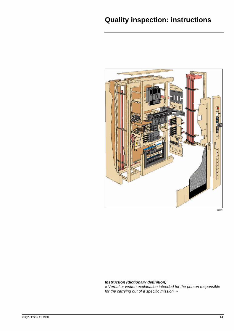
Instruction (dictionary definition) « Verbal or written explanation intended for the person responsible for the carrying out of a specific mission. »
E28373

Quality inspection: instructions
GIQ2 / ESB / 11.1998 15
6. Performing in-process inspection
6.1. Reminder The purpose of in-process inspection is to ensure product conformity after each manufacturing operation.
6.2. Composition n One assembly follow-up sheet is completed for each cubicle n It is used from the first assembly phase through to final inspection. n After each stage, the operator checks and declares product conformity by signing this sheet and noting any observations. n On completion of the inspections, a copy of this sheet is archived (see sheet example in the appendix).
7. Performing the final inspection The Quality Inspector must: n Take delivery of the switchboards to be inspected in the dedicated zone. n Examine the Project Design file n Check the observations and information given in the assembly follow-up sheet, n Perform the final inspection by following the list of tests to be carried out.
7.1. Conformity check
7.1.1. Enclosure n Appearance: o Colour and reference of paint: Use the colour palette to ensure that the reference of the paint given in the project file matches the colour of the cubicle. o Homogeneity: Perform a visual inspection to check the homogeneity of the colours of the various switchboard components (doors, panels, etc.). o Front face: Visually check that the front face of the cubicle matches that shown in the drawing of the project design file. o Finish: Check external appearance by an essentially visual inspection: no scratches, deformation, etc.

Quality inspection: instructions
GIQ2 / ESB / 11.1998 16
n Composition o Number and order of cubicles: Use the drawing of the front face of the project to ensure that the number and order of cubicles is respected. o Dimensions: Check the cubicle dimensions (height, width, length and depth) by measuring and comparing them with those stated in the project design file. o Type of form: Check the type of form against that defined in the project design file. o Mimic diagram: Check conformity of the mimic diagram compared with the power diagram. o Project identification label: – Check that the label is present and in the right position (normally it is placed at the top of the switchboard). – Check that the information marked on the label matches that in the project file o Cubicle identification markers: – Check the presence of an identification marker on each switchboard cubicle. This is normally shown in the form of a self-adhesive label. – Ensure that this label contains the registration number, signature, switchboard number and update version. – On completion of final inspection, the Quality Inspector must place his registration number or signature and indicate the date when the inspection was performed.
7.1.2. Framework n Ground fixing: Use the project design drawing to check the location of the ground fixing points and the layout of the various cubicles in the project. n Cable routing area: Check the special facilities provided for cable (top or bottom) routing or busbar trunkings. n Fixing of mounting plates, protection screens and partitioning or cowling parts: Check that all screws (and picot washers) for fixing these components are present, and check that screws are properly tightened. n Auxiliary screws: Check the presence of the screws required for joining the cubicles and for mounting fishplates and roofs. n “Danger” and “downstream live” warning plates: Ensure they are fitted if required by the product or customer.

Quality inspection: instructions
GIQ2 / ESB / 11.1998 17
n Equipment: o Use the project design file to ensure that the cubicle equipment is complete and has been installed properly (seal covers, base plates, cableways, awnings, etc.) o Panelling: Ensure the presence and proper fitting of: – the front, rear and end panels, – the roofs and bottom plates (steel, aluminium, etc.), – the doors (plain, transparent, etc.). o Conformity of cutouts in the plates: Using the drawing check the presence of any cutouts in the roofs and separation plates allowing fishplating of transfer busbars (mainly for MB 200), etc. o Checking the locks: Check matching of the lock references and the key numbers with the references given in the project design file. o Checking the degree of protection (I.P.): – This check is performed by checking the presence of the components guaranteeing the IP level stated in the project design file. Needs vary according to the required IP degree: awning, seal, front plate, etc. (information given in the product catalogues or guides). – If a seal is used, ensure it is properly positioned and continuous.
7.1.3. Switchgear n Location / identification: Use the layout diagrams in the project design file to ensure that the devices are properly placed and identified (QF1, QF2, etc.). At the same time, the nature of the labels associated with the devices and the content of the text can be checked using the project design file drawing. n Fixing the switchgear: Check the fixing of the devices on the mounting plates, doors, auxiliary compartment doors or front plates (checking that they are correctly fitted and that all the necessary screws are present). n Accessories: Visual checking of the presence of these accessories: o Crank handles for circuit-breaker extraction, o Locking of doors, o Clamps for fuse extraction, o Pins for fixing certain relays, o etc.

Quality inspection: instructions
GIQ2 / ESB / 11.1998 18
n Technical data: o For circuit-breakers: – Check the type, rating, breaking capacity and number of poles. Also check presence and technical data of their associated devices (vigi, SD switch, trip unit, etc.). – Check or carry out the settings for switchgear such as thermal and magnetic releases, time delays, etc. o Check the supply voltages for: – coils (contactors, relays, impulse relays, undervoltage or shunt coils of the Compact, Masterpact and multi 9), – switchgear motor mechanisms, – indicator lights, – all the electronic devices. All these checks must be made with respect to the project design file. n Toroids: Check the technical data of each toroid against the project design file and the customer connection cables. Also ensure the correct mounting direction: the arrow shows current direction. n Current transformer (CT): o Check the technical data of the current transformers against the project design file, together with the supply direction. For example: some manufacturers propose transformers where current must enter via P1 and leave via P2. o Check the correspondence between the current transformer and the associated device (ammeter, meter, etc.), ensuring that the current delivered by its secondary circuit is compatible with the device. o Check the clearances of the fixing screws and the connecting screws of the current transformer and particularly those near the live conductors or metal parts. n Shunt: Check the connection between the shunt and the measuring instrument. n Position of the indicators after a fault trip: trip the device, then examine the position of the indicators. n Plug-in protection flaps: Check the presence of the plug-in sealing flap. n Insulation screen / phase separator: Check they are fitted if required. n Accessibility: Check accessibility of the devices, settings, HPC fuses for replacement, coils.
E20545

Quality inspection: instructions
GIQ2 / ESB / 11.1998 19
n Safety perimeters: o Check the circuit-breaker safety perimeters referring to their installation guides, o Check if necessary, the various accessories necessary for proper operation. n Pre-tripping of the devices during plug-in and plug-out: Check operation of the mechanical systems for pre-tripping the plug-out devices on base or frame.
7.1.4. Busbars n Type: Check correspondence of the busbar type (Linergy, flat busbars) with the one shown on the project design file drawing. n Cross-section: According to nominal current (In), short-circuit current (Isc) and circuit-breaker breaking time, check that the cross-section corresponds to that shown in the switchboard technical guide. n Coating: Check the type of coating of the busbars (bare copper, tin-coated copper, sheathed busbars, epoxy paint, silver-plating, etc.). n Layout: o Check their position (horizontal, vertical) using the project design file layout drawing. o Check that the layout or arrangement of the busbars does not obstruct routing of cable connection cables. o Ensure the extension possibilities of the busbars according to specific features. n Marking: o Check correspondence of the type of labelling against the project design file. o Check that marking order (phases 1, 2, 3, neutral and PE) is respected according to the layout drawing. Phase order will be checked at a later stage. n Type of supports: Check their type referring to the switchboard technical guide. n Clearances / creepage distances: Check using the switchboard technical guide.
Quality inspection: instructions
GIQ2 / ESB / 11.1998 20
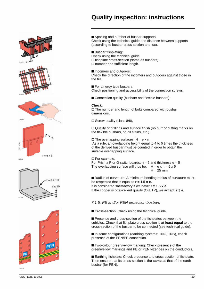
n Spacing and number of busbar supports: Check using the technical guide, the distance between supports (according to busbar cross-section and Isc). n Busbar fishplating: Check using the technical guide: o fishplate cross-section (same as busbars), o number and sufficient length. n Incomers and outgoers: Check the direction of the incomers and outgoers against those in the file. n For Linergy type busbars: Check positioning and accessibility of the connection screws. n Connection quality (busbars and flexible busbars): Check: o The number and length of bolts compared with busbar dimensions, o Screw quality (class 8/8), o Quality of drillings and surface finish (no burr or cutting marks on the flexible busbars, no oil stains, etc.). o The overlapping surfaces: H = e x n As a rule, an overlapping height equal to 4 to 5 times the thickness of the derived busbar must be counted in order to obtain the suitable overlapping surface. o For example: For Prisma P or G switchboards: n = 5 and thickness e = 5 The overlapping surface will thus be: H = e x n = 5 x 5 H = 25 mm n Radius of curvature: A minimum bending radius of curvature must be respected that is equal to r = 1.5 x e. It is considered satisfactory if we have: r ≥ 1.5 x e. If the copper is of excellent quality (CuETP), we accept: r ≥ e.
7.1.5. PE and/or PEN protection busbars n Cross-section: Check using the technical guide. n Presence and cross-section of the fishplates between the cubicles: Check that fishplate cross-section is at least equal to the cross-section of the busbar to be connected (see technical guide). n In some configurations (earthing systems: TNC, TNS), check presence of the PEN/PE connection. n Two-colour green/yellow marking: Check presence of the green/yellow markings and PE or PEN lozenges on the conductors. n Earthing fishplate: Check presence and cross-section of fishplate. Then ensure that its cross-section is the same as that of the earth busbar (for PEN).
E20473
E20480
E20472
E20479
E20483
E20581

Quality inspection: instructions
GIQ2 / ESB / 11.1998 21
7.1.6. Flexible busbars n Cross-section: To be checked according to the device rating using the technical guide. n Radius of curvature of the flexible busbars (at least once busbar thickness). n In the event of a superimposed busbar installation, ensure that insulating spacers are placed between the conductors to provide proper ventilation. n Binding: Check that the type and number of bindings used correspond to those marked in the LV switchboard implementation guide. For example: No direct binding on metal parts. If necessary fit an insulating wedge. n Check the connections: presence of the thick washer and the contact washer (see LV switchboard implementation guide).
7.1.7. Cables n Cross-section of power, auxiliary and protection conductors: Check cross-section referring to the switchboard technical guide. n Nature of cables: Check that they are Ui 1000 V insulated, with an utilisation temperature of <105°C and self-extinguishing (Schneider recommendation). n Protection of cables: Check that the cables do not run near sharp edges, moving parts or exposed live parts. n Radius of curvature: Ensure that the cable radius of curvature is roughly 6 to 8 times cable diameter. n Number of cables per strand: Refer to the switchboard implementation guide. n Separating the strands: Check that the power and control strands are separated as well as the strands receiving an auxiliary voltage of more than 500V AC-DC. n Wiring trunking: Ensure that the reserve in the trunkings is approximately 20% and that their fasteners are made of insulating accessories (e.g. polycarbonate screws). n The maximum centre distance between two trunking fasteners must not exceed 600mm.
E20540
E20532
entraxe max.

Quality inspection: instructions
GIQ2 / ESB / 11.1998 22
n No cables must be inserted between the power bars. n Cable fixing: Use the technical guide to ensure that the number of cable tie-bars, the quality of fastening according to lsc and the type of binding used are correct.
7.1.8. Connections n Three types of inspection are performed according to the connections : o Visual inspection (A) : – Of the crimping recess (quality, pressure, etc.), – Of proper cable insertion, – Of the position of the conductor core in the lug shaft, – Of cable cross-section compared with lug cross-section. o Mechanical inspection (B) by manual traction (performed by random sampling). o Visual inspection (C) of presence and direction of contact washers (flat washers + “contact” washers on flexible busbars and oblong holes), and presence of varnish certifying tightening to the right torque (on visible connections). In event of doubt (number of threads protruding from the nut, for connections of the same type, differs on screws of the same length, contact washers excessively crushed or moving), carry out a sampling check. If a number of faults are detected, ask the person responsible for assembling it to repair the LV switchboard. The following table gives the inspections to be performed according to the type of connection used: Connections Power Other circuits
Lugs A + C B + C
Clips B B
Cable connectors A B
Terminals B + C B
Nuts-washers contacts
C C
(reference: PR 309/A) Where A, B, C stand for the various inspection types. A = visual inspection B = mechanical inspection C = checking presence and positioning. n Accessibility of power connection points and terminal blocks: Check accessibility of the connection points so that the customer can connect according to the radius of curvature of the cables.
E20485
E20488

Quality inspection: instructions
GIQ2 / ESB / 11.1998 23
n Possibility of connecting cables on pads or terminals: Refer to the technical guide and the project design file. o Check that the number of holes matches the number of cables with which the customer connects. o Check that the cross-section and number of cables ensure compliance with clearances.
7.2. Mechanical checks n Operation of doors, mechanical accessories and drawers: Check their operation by manoeuvring them. n Manual controls of mechanisms: Manoeuvre the manual control devices to ensure their proper operation. n Resetting after fault trip: Check that the circuit-breaker is reset after an electrical fault trip or after pressing the tripping test button. n Locking systems: a. interlockings: Check that closing of one circuit-breaker prevents closing of the other(s). o Locking by rods: Check their mechanical fasteners. o Locking by cables: Check its radius of curvature using the installation guide and ensure that they are not fixed near exposed live parts. o Locking by key-locks, check: – the type and references of the key-locks. – that the key-lock prevents the device from operating. b. Plug-in / Plug-out: o Check that operation is impossible when the device is closed. o Check pre-tripping of the devices on plug-in and plug-out. c . ensure sturdiness of the various locking systems: o Polarisation: Check that the position of the polarising slots matches the specification (MCC drawers). With respect to switchgear, check their polarising code referring to the device polarisation manual. o Interchangeability between drawers and circuit-breakers: Check the possibility of interchangeability of circuit-breakers and drawers of the same type.
E18622 E18622
E21399 E21399
E26766
Quality inspection: instructions
GIQ2 / ESB / 11.1998 24
7.3. Electrical checks
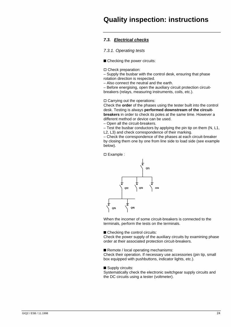
7.3.1. Operating tests n Checking the power circuits: o Check preparation: – Supply the busbar with the control desk, ensuring that phase rotation direction is respected. – Also connect the neutral and the earth. – Before energising, open the auxiliary circuit protection circuit-breakers (relays, measuring instruments, coils, etc.). o Carrying out the operations: Check the order of the phases using the tester built into the control desk. Testing is always performed downstream of the circuit-breakers in order to check its poles at the same time. However a different method or device can be used. – Open all the circuit-breakers. – Test the busbar conductors by applying the pin tip on them (N, L1, L2, L3) and check correspondence of their marking. – Check the correspondence of the phases at each circuit-breaker by closing them one by one from line side to load side (see example below). o Example :
When the incomer of some circuit-breakers is connected to the terminals, perform the tests on the terminals. n Checking the control circuits: Check the power supply of the auxiliary circuits by examining phase order at their associated protection circuit-breakers. n Remote / local operating mechanisms: Check their operation. If necessary use accessories (pin tip, small box equipped with pushbuttons, indicator lights, etc.). n Supply circuits: Systematically check the electronic switchgear supply circuits and the DC circuits using a tester (voltmeter).
Qf2
Qf5 Qf6
Qf3 Qf4
Qf1

Quality inspection: instructions
GIQ2 / ESB / 11.1998 25
n Electrical indications: o Check the presence of the power on indicator lights. o Check the function of these indicator lights. o Ensure their correspondence with the associated devices (“on” indicator light for “on” position, etc.). n Information supplied on the connection terminals: o Check contact status (open or closed on make or break according to required operation). o Check the remaining information (voltage, current, etc.) by measuring it using a suitable device. n Motor mechanisms (contactors, relays, etc.): o Close the protection devices to be checked. o Activate the operating mechanism of these devices using pushbuttons or relays. n Electrical lockings: Check that it is impossible to close a device equipped with a locking contact. n Metering circuits: To check the metering circuits, the CT secondary must be supplied using a phase shift box (failing this, you can use any other calibrated device offering the same possibilities). o Example of carrying out the operations: – Select the supply voltage, – Adjust the maximum value of the current to be injected in the secondary circuit, – Inject the current in one of the circuits or in all three at once to check cabling. n Checking the test function: Circuit-breaker operation is checked by a variety of tests according to device type: o Earth leakage module test (Multi 9 range, NS range): – Close the circuit-breaker. – Press the test button of the Vigilohm part. This test is used to regularly check device tripping by simulating an earth fault. o Trip unit test (NS and Masterpact range): This test is performed using an external electronic tripping box. – Close the circuit-breaker. – Make it trip using the box by connecting its cord to the specially provided socket on the front face of the trip unit part. – For increased dependability, repeat this operation. o Testing the mechanical part: – Press the test button (normally red). – Check circuit-breaker tripping. o If the circuit-breaker opens for each test, the device operates correctly.

Quality inspection: instructions
GIQ2 / ESB / 11.1998 26
n Voltage relays, time delay relays, fault tracking devices: o For the voltage relays, check that the contacts are in the status defined in the project design file. o For the time delay relays, check correct operation of the time delays. o For the fault tracking devices, create a fault and check that the device detects and indicates its presence. In order to create a fault, a resistance box can be supplied as shown below: Pre-set the value of the resistance required to create a fault according to toroid characteristics. Make the resistance vary by reducing its value. When you fall below the pre-set value, the device must indicate the fault. n Time delay settings: Check that these settings comply with the project design file.
7.3.2. Dielectric withstand (Standard IEC 439.1 paragraph 8.3.2)
n Preparation : o The dielectric test is always performed before the insulation test. o Do not forget to remove the covers from the Vigi modules of the Compact NS.
L1
L2
L3
N
Resistor
box
Load
To the fault tracking device
Quality inspection: instructions
GIQ2 / ESB / 11.1998 27
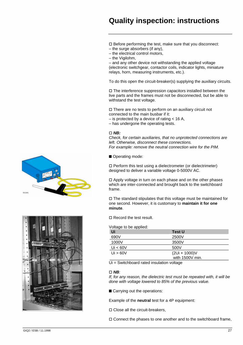
o Before performing the test, make sure that you disconnect: – the surge absorbers (if any), – the electrical control motors, – the Vigilohm, – and any other device not withstanding the applied voltage (electronic switchgear, contactor coils, indicator lights, miniature relays, horn, measuring instruments, etc.). To do this open the circuit-breaker(s) supplying the auxiliary circuits. o The interference suppression capacitors installed between the live parts and the frames must not be disconnected, but be able to withstand the test voltage. o There are no tests to perform on an auxiliary circuit not connected to the main busbar if it: – is protected by a device of rating < 16 A, – has undergone the operating tests. o NB: Check, for certain auxiliaries, that no unprotected connections are left. Otherwise, disconnect these connections. For example: remove the neutral connection wire for the PIM. n Operating mode: o Perform this test using a dielectrometer (or dielectrimeter) designed to deliver a variable voltage 0-5000V AC. o Apply voltage in turn on each phase and on the other phases which are inter-connected and brought back to the switchboard frame. o The standard stipulates that this voltage must be maintained for one second. However, it is customary to maintain it for one minute. o Record the test result. Voltage to be applied:
Ui Test U 690V 2500V 1000V 3500V Ui < 60V 500V Ui > 60V (2Ui + 1000)V
with 1500V min. Ui = Switchboard rated insulation voltage o NB: If, for any reason, the dielectric test must be repeated with, it will be done with voltage lowered to 85% of the previous value. n Carrying out the operations: Example of the neutral test for a 4P equipment: o Close all the circuit-breakers, o Connect the phases to one another and to the switchboard frame,
E21261

Quality inspection: instructions
GIQ2 / ESB / 11.1998 28
o Interconnect all the switchboard frames and earth them, o Connect the measuring instrument earthing wire to the switchboard frame, o Place the pin tip in contact with the circuit to be monitored and gradually increase voltage up to the required value, o Maintain this voltage for one minute, o Gradually reduce voltage before disconnecting, o Record the result and note it on the measuring sheet, o Once this check is complete, repeat it for the other conductors. n Result: The tests are satisfactory if there is no bypass, deterioration of the insulators or perforation.
7.3.3. Insulation resistance n Check preparation: Disconnect: o The circuit-breaker electrical control motors and Vigilohms together with any other device not withstanding the applied voltage. o Some devices, so as not to create connections between the live conductors (such as coils, relays, indicator lights, contactor electromagnets, etc.) and the loads such as measuring instruments. n Operating mode: Using an insulation measuring instrument (megohmmeter), measure insulation at a voltage of 500 V DC. This measurement is taken between each live conductor and the two or three other conductors connected to the switchboard frame. n Carrying out the operations: The procedure is the same as the one used for testing dielectric withstand. n Result: The test is correct if insulation resistance between the circuits and the frame is at least 1000 Ohms/V with respect to the voltage of this circuit (NB: for our LV switchboards, the usual value of this insulation resistance is approximately 1 megohm).

Quality inspection: instructions
GIQ2 / ESB / 11.1998 29
7.3.4. Electrical continuity of the protection circuits (standard IEC 439.1 paragraph 8.3.3)
The inspection is either visual or electrical as required by the customer. n Visual inspection: This inspection is performed by checking the presence of component parts such as picot washers, earthing braids, etc. o For earthing braids, check the presence and direction of the picot washers (see electrical switchboard implementation guide) as well as their withstand by exerting a slight pressure on their connections. n Electrical inspection: NB: There is no device enabling this continuity to be checked. The method given is only for information. o Operating mode: A DC source is used, with an electromotive force of less than 6 V. A 2 A current is injected between the inlet of the earth busbar and the parts to be inspected (doors, front face, frame, etc.).
Measured resistance: R = U / I n Result: The inspection is satisfactory if the measured resistance is less than 0.1 Ohm.
6 V DC 2 A
V
A
U measur.
I measur.
Generator
Earth bar
Part to be tested
Appendix
GIQ2 / ESB / 11.1998 30

Appendix
GIQ2 / ESB / 11.1998 31
8. Quality indicator chart
8.1. Purpose The purpose of this chart is to measure quality performance and perform the necessary corrective actions to progress.
8.2. Principles The quality assurance manager issues a monthly quality report entitled “Quality indicator chart”. This document is intended for the unit manager, the site department managers and the quality assurance managers of the activity in the division.
8.3. Scope Performance is evaluated in the Groupe Schneider according to the four indicators below: n NQA : purchased non quality. n NQP : produced non quality. n NQS : service non quality. n NQE : customer complaints. n The non quality index: o is an indicator used to measure changes in non quality, o defines the target aims, o reveals the weaknesses of the various operations and allows the relevant action to be taken. n These non quality indices can be calculated using specific formulas that are found in the quality indicator chart form. With respect to quality inspection, the index directly associated with the final inspection is produced non quality.
Plant
Suppliers
Customers
Purchased Non-Quality Service
Non-Quality
Produced Non-Quality
External Non-Quality
Appendix
GIQ2 / ESB / 11.1998 32
n Purchased non quality is monitored by means of 3 indicators: o global ratio, o ratio outside the group, o Schneider ratio. n External non quality: Taking customer complaints into account (intermediate or end).
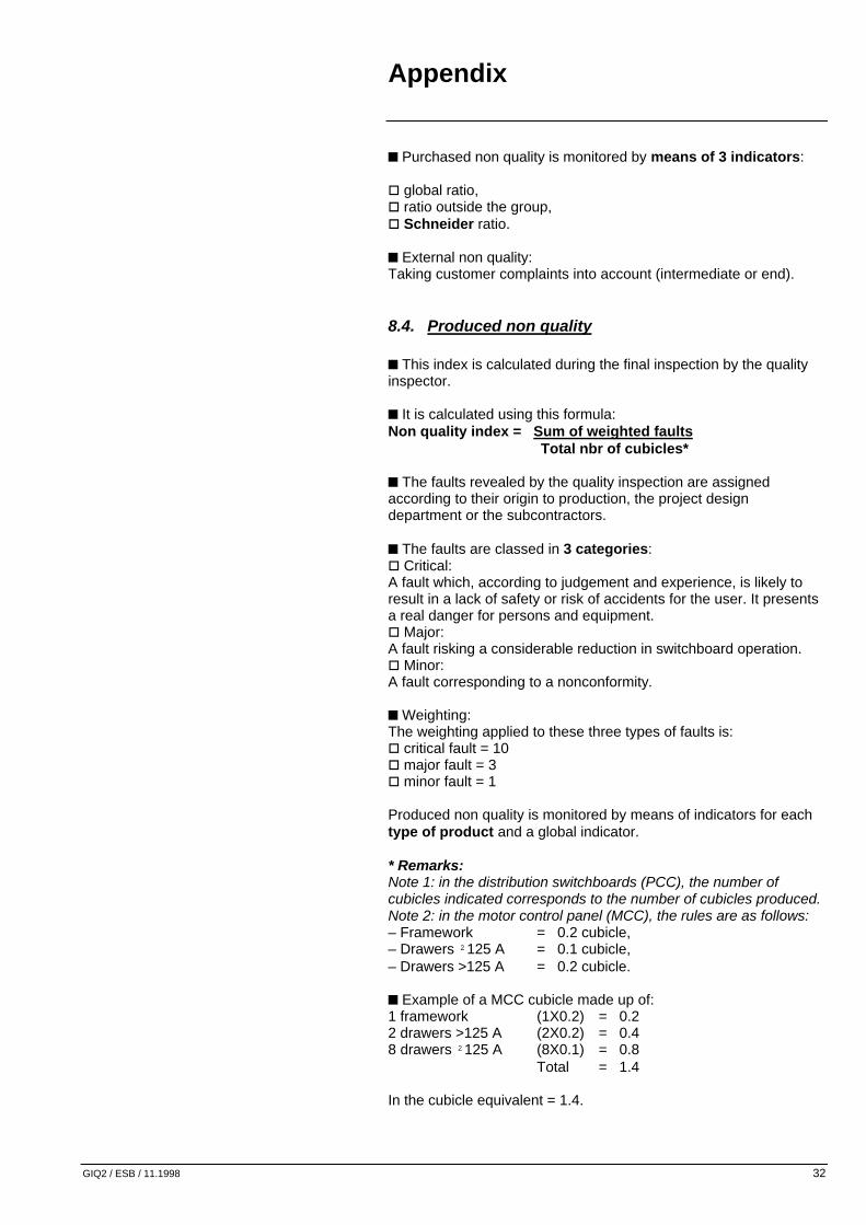
8.4. Produced non quality n This index is calculated during the final inspection by the quality inspector. n It is calculated using this formula: Non quality index = Sum of weighted faults Total nbr of cubicles* n The faults revealed by the quality inspection are assigned according to their origin to production, the project design department or the subcontractors. n The faults are classed in 3 categories: o Critical: A fault which, according to judgement and experience, is likely to result in a lack of safety or risk of accidents for the user. It presents a real danger for persons and equipment. o Major: A fault risking a considerable reduction in switchboard operation. o Minor: A fault corresponding to a nonconformity. n Weighting: The weighting applied to these three types of faults is: o critical fault = 10 o major fault = 3 o minor fault = 1 Produced non quality is monitored by means of indicators for each type of product and a global indicator. * Remarks: Note 1: in the distribution switchboards (PCC), the number of cubicles indicated corresponds to the number of cubicles produced. Note 2: in the motor control panel (MCC), the rules are as follows: – Framework = 0.2 cubicle, – Drawers ²125 A = 0.1 cubicle, – Drawers >125 A = 0.2 cubicle. n Example of a MCC cubicle made up of: 1 framework (1X0.2) = 0.2 2 drawers >125 A (2X0.2) = 0.4 8 drawers ²125 A (8X0.1) = 0.8 Total = 1.4 In the cubicle equivalent = 1.4.

Appendix
GIQ2 / ESB / 11.1998 33
8.5. Example of a Produced Non Quality index switchboard
Product Number Non
conform Faults Responsibilities Weighting
version
Nbr % A B C Weight. total
Prod. Project design dept.
Ext.
equip. 1 12.0 3 25 5 2 0 11 4 2 1 0.92 equip. 2 5.0 4 80 3 3 1 22 3 1 3 4.44 equip. 3 8.0 4 50 4 0 1 14 4 0 1 1.75 Total 25.0 11 44 12 5 2 47 11 3 5 1.88
Equipment 1: Prisma A: Minor = 1. Equipment 2: MB 100 / 200 B: Major = 3. Equipment 3: MB 400 C: Critical = 10.
8.6. Example of a graph showing the non quality index
0
1
2
3
4
5
6
J A S O N D J F M A
TargetIndex
n The peaks shown on the graph of the previous page may be due to: o the number of projects handled, o the complexity of certain projects (complicated operating sequence), o insufficient personnel training, o insufficient sensitivity of personnel, o poor control of supplies, o poor quality of the project design file.
Appendix
GIQ2 / ESB / 11.1998 34
9. Control of inspection means
9.1. Purpose The purpose of this section is to control the inspection and production means used in the unit.
9.2. Reminders of basic principles n Inspection means o List and identify the inspection means, o Have them checked at specific intervals, according to the accuracy of the measurements to take, by an approved international or national organisation. (For example, the organisation for France is the B.N.M. – National Metrology Office), o Identify by a label “not followed up in calibration”, the devices not assigned to measurement (e.g. power on detection devices), o Store, use and transport these means in conditions guaranteeing their proper operation and level of accuracy, o Rule on the project equipment delivered and inspected using nonconform measuring instruments. n Production means o Torque wrenches. o Crimping means.
9.3. Responsibility The inspection and production means manager appointed by the quality manager is responsible for: n listing and identifying these means, n implementing and monitoring the checks, n decision-making after checking, n archiving the documents.

Appendix
GIQ2 / ESB / 11.1998 35
9.4. General diagram of operations
9.5. Application rules
9.5.1. Choice of means Inspection means are chosen according to: n the type of measurement, n the theoretical values to be measured, n the required accuracy.
9.5.2. Classification of means n For checking follow-up: All the inspection means identified and monitored during checking that are used for inspection. n The items of equipment identified by a label “not followed up in calibration” and listed on the associated document are used as indicators. NB: the electrical test desks are qualified by the QI manager.
Technical comparison
Measurement results
Checking Calibration
Comparing results with the documented specification
Non-Conform Conform
Adjusting Repairing Derating Reworking
Updating the life sheet Putting (back) into operation
Check report life sheet
Calibration document
Check reference
Calibration reference Decision
Appendix
GIQ2 / ESB / 11.1998 36
9.5.3. Checking frequency n Inspection means The normal frequencies chosen are: o 1 check once a year for normally used inspection means (type: dielectrometer, etc.), o 1 check once every 2 years for seldom used inspection means (e.g. oscilloscope, etc.). n Production means o Torque wrenches: Must be calibrated once a year at least. o Crimping means: Must be checked once a year.
9.5.4. Listing and monitoring the inspection means n A list of inspection means plus a checking schedule are updated by the manager. n Each inspection means has a life sheet, which is opened for each acquisition and completed after each check by the manager. n A label is placed on each inspection means by an authorised organisation, such as BNM for France. It gives the check date and the date of the next check to be carried out. n The checking reports, measurement readings and nonconformity sheets transmitted by the organisation are filed with the life sheet.
9.5.5. Occasional checks These checks must be performed after: n Acquisition of a new inspection means (without verification or conformity certificate), n An impact, n A repair, n A loan, n A long period of inactivity.
9.5.6. Devices outside the accuracy class Should the calibration organisation declare the inspection means to fall outside the accuracy class, it is up to the manager to isolate it and implement one of the decisions listed below: n Repair, n Derating to an inspection means not assigned to measurement, n Scrapping.

Appendix
GIQ2 / ESB / 11.1998 37
He must also decide whether to initiate a Notification of NonConformity (NNC) used to rule on project equipment delivered which is inspected using the device in question as follows:
* See the example of Notification of NonConformity.
Prepare an NNC
Effects on product
operation or on safety of people and equipment
Analyse
List the projects delivered and tested using the faulty means
Contact customers
Programme intervention
Settle the NNC after correction
yes
Settle the NNC*
no
Who
Calibration manager Quality department manager

Appendix
GIQ2 / ESB / 11.1998 38
10. List of equipment
10.1. The Quality Inspector’s tools These are the switchboard fitter’s tools (screwdriver, wrenches, etc.) with in addition: n A small rule to check clearances, n A lamp, n An articulated mirror.
10.2. Switchgear common to the Quality Inspection n Control desk, n Dielectrometer or dielectrimeter, n Megohmmeter, n Peak demand, phase order tester, n The Quality Inspector should have at his disposal: mounting plate, test cords and a variety of plugs, supply cords and other connection systems, n Some devices are seldom used and act only as an indicator (e.g. oscilloscope, cubicle scales, etc.).
E21258
E21259
E21257

Appendix
GIQ2 / ESB / 11.1998 39
11. Example of measuring means accuracy
Type of measurement Example of the type of device to be used
Required accuracy Device accuracy
Voltage measurement: – ac: 0-650V – dc: 0-250V
n Peak demand o MX522 (Metrix). o MX570 (Metrix). n Kit DHF MTM 3US2
5%
o 0.5% o Digital 0.1% o Anal. 1.5% o 1%
Current measurement 0-10A 0-50A
n Peak demand o MX522 (Metrix). o MX570 (Metrix). n Kit DHF MTM 3U S2.
5%
o 0.5% o 1%
Resistance measurement n Peak demand
o MX522 (Metrix). o MX570 (Metrix).
5%
o 0.5%
o Digital 0.1% o Anal. 1.5%
Insulation measurement n Megger BM6. n Chauvin Arnoux Isoca. n ELK VH 27. n Bouchet A 509. n Sefelec MG50.
Temperature measurement
Metrix HA 1159.
5% o 2° from 0 to 70 o 3° from 70 to 120°
Length measurement n Sliding caliper: o Mittutoyo CD 15D o Storm.
0.1mn (Dimension measurement up to 200m)
o 0.02mn o 0.01mn
Coating thickness measurement on ferrous and non-ferrous metals:
Elcometer 345-022322
n Paint on steel sheet:10 microns n Nickel and Zinc on steel: 2 microns
3% of value read
Signal readings: Metrix Oscilloscope
Circuit-breaker tripping test
Merlin Gerin
Dielectric withstand Bouchet A507 (or A884) Chauvin Arnoux MC5B.
Appendix
GIQ2 / ESB / 11.1998 40
12. Useful addresses Refer to the tool guide « addition to low voltage switchboard guides » (ESB / GO2 / 11.98).
13. File example
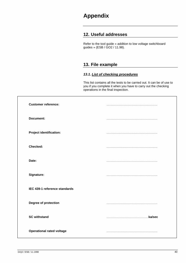
13.1. List of checking procedures This list contains all the tests to be carried out. It can be of use to you if you complete it when you have to carry out the checking operations in the final inspection.
Customer reference: .....................................................................................
Document: .....................................................................................
Project identification: .....................................................................................
Checked: .....................................................................................
Date: .....................................................................................
Signature: .....................................................................................
IEC 439-1 reference standards
Degree of protection .....................................................................................
SC withstand ......................................................................ka/sec
Operational rated voltage .....................................................................................

Appendix
GIQ2 / ESB / 11.1998 41
1. Composition o Number of cubicles o Order of cubicles o Cubicle identification o Handling device o Switchboard and cubicle identification markers o "Man struck by lightning" plates for U ≥ 660 V or form door
2. Appearance Paint o MG paint colour and reference o Finish - Homogeneity o No scratches or deformation
3. Framework o Dimensional inspection – Switchboard – Length – Width – Height – Depth – Fixing points. o Operation of doors and mechanical accessories o Inspecting key-locks and key numbers o Operation of drawers o Checking the degree of protection
4. Conformity of the devices installed Checking o Conformity of the devices installed (circuit-breakers – contactors – thermal relays - etc) o Their type and rating / o Device breaking capacities o Safety perimeters o Manual controls of mechanisms o Interlockings o Plug-in protection flaps o Fault trip indicators o Compacts NS motor mechanisms
5. Checking the electrical connections Busbars n Checking the busbars: o Spacing and number of BB supports for electrodynamic withstand. o Type of supports (conformity with product technical file) o Busbar fishplating n Accessibility of: o Phase rotation o Effective continuity of the earthing circuit (take care with EMC compatibility) o Presence of the earthing fishplate o Cross-section of the protection conductor.
Appendix
GIQ2 / ESB / 11.1998 42
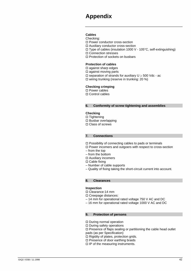
Cables Checking: o Power conductor cross-section o Auxiliary conductor cross-section o Type of cables (insulation 1000 V - 105°C, self-extinguishing) o Connection stresses o Protection of sockets on busbars Protection of cables o against sharp edges o against moving parts o separation of strands for auxiliary U ≥ 500 Vdc - ac o wiring trunking (reserve in trunking: 20 %) Checking crimping o Power cables o Control cables
6. Conformity of screw tightening and assemblies Checking o Tightening o Busbar overlapping o Class of screws
7. Connections o Possibility of connecting cables to pads or terminals o Power incomers and outgoers with respect to cross-section – from the top – from the bottom o Auxiliary incomers o Cable fixing – Number of cable supports – Quality of fixing taking the short-circuit current into account.
8. Clearances Inspection o Clearance:14 mm o Creepage distances: – 14 mm for operational rated voltage 750 V AC and DC – 16 mm for operational rated voltage 1000 V AC and DC
9. Protection of persons o During normal operation o During safety operations o Presence of flaps sealing or partitioning the cable head outlet pads (as per Specification) o Rigidity of plates, protection grids. o Presence of door earthing braids o IP of the measuring instruments.

Appendix
GIQ2 / ESB / 11.1998 43
10. Accessibility o Functional units or devices o Terminal blocks manually or using a screwdriver
11. Interchangeability of drawers o Polarisation o Electrical interchangeability between drawers and circuit-breakers
12. Checking locking systems o Pre-tripping of devices on plug-in and plug-out operations o Correct resetting of devices after a fault trip (circuit-breaker, relay, etc.) o Impossibility of plugging in a drawer when the device is closed o Impossibility of plugging out a drawer when the device is closed o Sealing flaps on the power circuits o Sturdiness of the locking systems by key-locks or padlocks o Operating safety (jamming – safety margin)
13. Checking mechanical settings Check o Limit travel contacts: circuit-breaker - drawer - etc. – Plug-in position - test . – Plug-out position - free o Contactor pretripping o Tripping on fuse blowing o Cubicle back micros o Circuit-breaker rod assemblies (Normal/Standby Source Changeover switches – switches) o Power plug-in penetrations o Freedom of the power clamp fingers – of contact pressure
14. Checking serviced devices o Fitting or removing the arc chutes (contactors, circuit-breakers, etc.) o Access to HPC fuses for replacement o Ease of fitting or removing covers, front plates, etc.
15. Operating inspection Check o IT inlets and outlets o Winding direction o Wiring and the various operating sequences o Local and remote controls o Mechanical electrical indications o Electrical controls and mechanisms o Electrical locking o Protection and metering circuits o Time delay setting

Appendix
GIQ2 / ESB / 11.1998 44
16. Measuring dielectric withstand
Circuit tested ϕ1 ϕ2 ϕ3 N Aux
Nominal voltage
Applied voltage
Leakage current
Result
17. Insulation resistance measurement
Circuit tested ϕ1 ϕ2 ϕ3 N Aux
Nominal voltage
Insulation resistance
Result
18. Monitoring protection circuits o Visual o By tests
19. Inspection prior to dispatch Check o Roofs, seal covers and fixing screws o End panels and fixing screws o Sealing flaps (+ screws), openings for access to the cubicle anchoring points o Cubicle coupling screws o Conformity of cutouts in the separation plates for insertion of the transfer busbars (or cables) o Seals according to the IP (those mounted after installation) o Fishplates (nature) and associated screws o Circuit-breaker extraction crank handles: - Masterpact - C 1250, etc. o Device lifting handles o Extraction clamps for L fuses o Accessories for protecting wires between cubicles o Separate equipment o Cubicle anchoring bolting (if stipulated in Specification) o Devices dismantled for transportation o Door handle keys: key-locking o The list of equipment not delivered (missing)
Appendix
GIQ2 / ESB / 11.1998 45
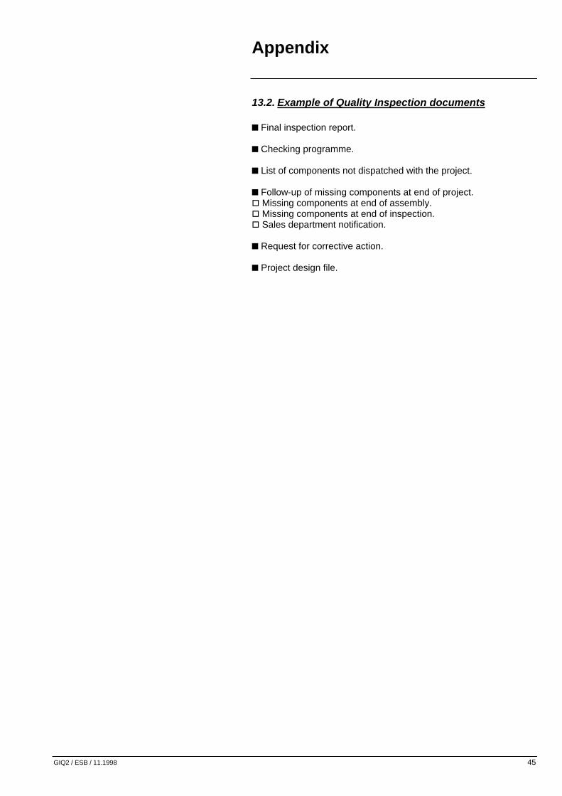
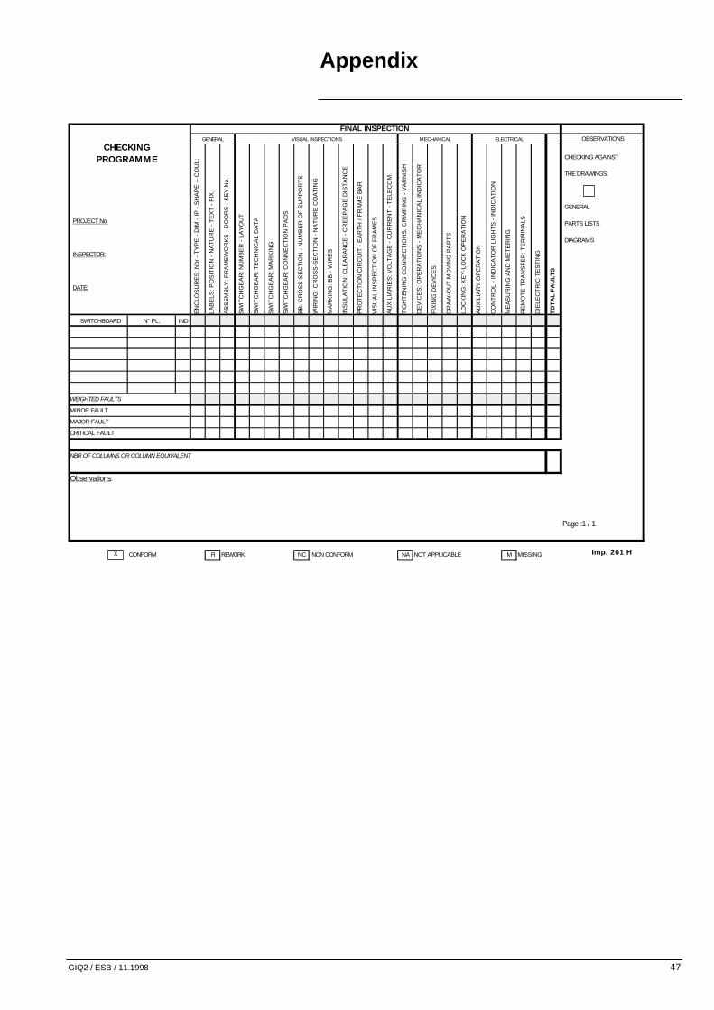
13.2. Example of Quality Inspection documents n Final inspection report. n Checking programme. n List of components not dispatched with the project. n Follow-up of missing components at end of project. o Missing components at end of assembly. o Missing components at end of inspection. o Sales department notification. n Request for corrective action. n Project design file.

Appendix
GIQ2 / ESB / 11.1998 46
Procès verbal de contrôle finalFinal inspection record
Client / Customer : ........................................................... PV n° / Certif Nr ........................................Affaire / Projet : ........................................................... N° Cde client / Customer ref : .......................Nom du tableau / Switchboard identification .................. .....................................................................................................................................................................: N° affaire / Job ref . : .....................................Type de produit /Product : .................................................Quantité / Qty : ................................................. Fin contrôle Exped.Plan n° / DRWG Nr : ................................................. Indice / Index :
Gamme de contrôle / Checking program
1. Contrôle de conformité / conformity checking
- Les enveloppes / Enclosures ...........................................................
- L'appareillage / Switchgear ...........................................................
- Les conducteurs / Conductors ...........................................................
2. Vérifications mécaniques/ mechanical checking
3. Continuité électrique des masses mécaniques Visuel / Visual
Exposed conductive parts electrical continuity Electrique / Electrical
Réf. appareil de mesure / meter ref.
Valeur / Value
4. Essais diélectriques / dielectric testdielectric test Réf. appareil de mesure / meter ref.
Circuit / Circuit Auxiliaires / Auxiliaries Puissance / PowerTension nominale / nominal volt VTension injection / injection volt V
5. Essais d'isolement / insulating test Réf. appareil de mesure / mesure ref.
Circuit / Circuit Auxiliaires / Auxiliaries Puissance / PowerTension d'applicat./ Applied voltage VValeur d'isolement / Insulation value V
6. Essais d'isolement / performances electric test......................................
Observation / comment :
Inspecteur client Inspecteur qualité Respons. I.QCustomer représentative Quality inspector Quality manager
Date Date Visa
Visa Visa
Appendix
GIQ2 / ESB / 11.1998 47
FINAL INSPECTIONGENERAL VISUAL INSPECTIONS MECHANICAL ELECTRICAL OBSERVATIONS
EN
CLO
SU
RE
S: N
br -
TY
PE
- D
IM -
IP -
SH
AP
E -
- C
OU
L;
LAB
ELS
: PO
SIT
ION
- N
AT
UR
E -
TE
XT
- F
IX.
AS
SE
MB
LY: F
RA
ME
WO
RK
S -
DO
OR
S -
KE
Y N
o.
SW
ITC
HG
EA
R: N
UM
BE
R -
LA
YO
UT
SW
ITC
HG
EA
R: T
EC
HN
ICA
L D
AT
A
SW
ITC
HG
EA
R: M
AR
KIN
G
SW
ITC
HG
EA
R: C
ON
NE
CT
ION
PA
DS
BB
: CR
OS
S-S
EC
TIO
N -
NU
MB
ER
OF
SU
PP
OR
TS
WIR
ING
: CR
OS
S-S
EC
TIO
N -
NA
TU
RE
CO
AT
ING
MA
RK
ING
: BB
- W
IRE
S
INS
ULA
TIO
N: C
LEA
RA
NC
E -
CR
EE
PA
GE
DIS
TA
NC
E
PR
OT
EC
TIO
N C
IRC
UIT
- E
AR
TH
/ F
RA
ME
BA
R
VIS
UA
L IN
SP
EC
TIO
N O
F F
RA
ME
S
AU
XIL
IAR
IES
: VO
LTA
GE
- C
UR
RE
NT
- T
ELE
CO
M.
TIG
HT
EN
ING
CO
NN
EC
TIO
NS
: CR
IMP
ING
- V
AR
NIS
H
DE
VIC
ES
: OP
ER
AT
ION
S -
ME
CH
AN
ICA
L IN
DIC
AT
OR
FIX
ING
DE
VIC
ES
DR
AW
-OU
T M
OV
ING
PA
RT
S
LOC
KIN
G: K
EY
-LO
CK
OP
ER
AT
ION
AU
XIL
IAR
Y O
PE
RA
TIO
N
CO
NT
RO
L -
IND
ICA
TO
R L
IGH
TS
- IN
DIC
AT
ION
ME
AS
UR
ING
AN
D M
ET
ER
ING
RE
MO
TE
TR
AN
SF
ER
: TE
RM
INA
LS
DIE
LEC
TR
IC T
ES
TIN
G
TO
TA
L F
AU
LT
S
SWITCHBOARD N° PL. IND
WEIGHTED FAULTS
MINOR FAULT
MAJOR FAULT
CRITICAL FAULT
NBR OF COLUMNS OR COLUMN EQUIVALENT
Observations:
Page :1 / 1
CONFORM R REWORK NC NON CONFORM NA NOT APPLICABLE M MISSING
CHECKING AGAINST
THE DRAWINGS:
PROJECT No:
INSPECTOR:
DATE:
CHECKING PROGRAMME
GENERAL
PARTS LISTS
DIAGRAMS
X Imp. 201 H
Appendix
GIQ2 / ESB / 11.1998 48
Merlin Gerin - L.V Switchboards Plant
Tel : 00.00.00.00.00. Fax: 00.00.00.00.00.
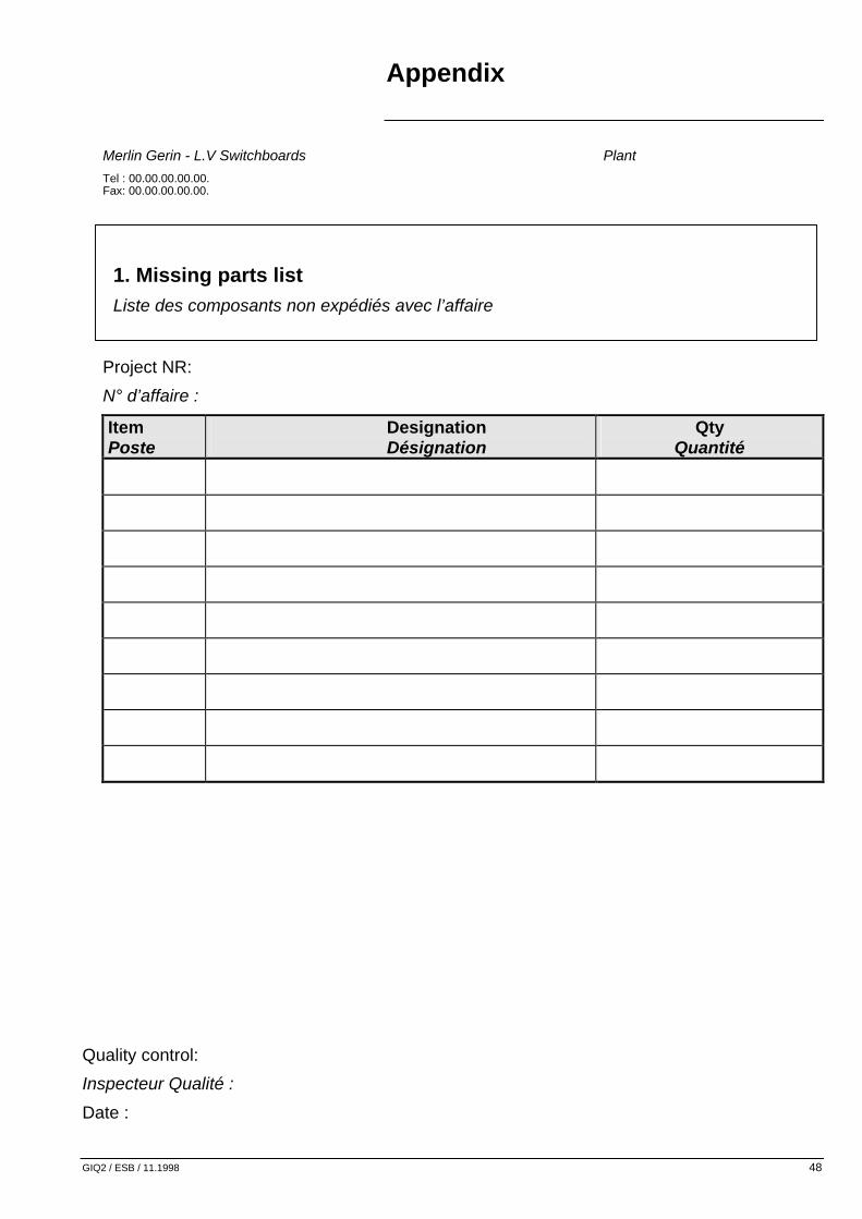
1. Missing parts list Liste des composants non expédiés avec l’affaire
Project NR: N° d’affaire :
Item Poste
Designation Désignation
Qty Quantité
Quality control:
Inspecteur Qualité :
Date :

Appendix
GIQ2 / ESB / 11.1998 49
2. Follow-up of missing parts at end of project
Project no. : Date received by customer or factory
availability lead time
1 Missing at end of assembly
Issued by: Manu è I.M. è Supply è I.M. Date : (copy) è IQ.I.
Items Project co-ordinator Quantities Supplies References Lead time announced

Appendix
GIQ2 / ESB / 11.1998 50
2 Missing parts at end of inspection/custormer acceptance
Issued: Q.I. è I.M. è Supply è I.M. è S.E.I.M. è S.E. Date: (copy) è Q.I. (copy) è Warehouse
Items Quality inspector Quantities Supplies References Lead time
announced
3 Sales department notification
Can the project be dispatched with missing parts? Yes No
Must the missing parts be partially dispatched? Yes No
Wich ones?
_______________________________________________________________________
Missing parts _______________________________________________________________________
dispatch address: ________________________________________________________________________
Project site delivery date: ________________________________________________

Appendix
GIQ2 / ESB / 11.1998 51
C O R R E C T IV E A C T IO N R E Q U E S T
A .R . o f
D a te :
F r o m : T o :
C o p y t o :
N o n c o n f o r m i ty d e te c te d b y c u s to m e r d e te c te d in te r n a lly
P r o d u c t in q u e s t io n : P r o je c t n o :
I s s u e d b y : D a te : C u s to m e r :
D e s c r i p t i o n o f t h e n o n c o n f o r m i t y
A n y s u g e s t io n s
A n s w e r
C o r r e c t iv e a c t io n s P e r f o m e d b y D a te
R C A s e t t le d D a te Q .A . s ig n a tu r e
Im p . 2 0 5 A

Inspection qualité des tableaux basse tension : Tableau de bord Qualité Quality inspection of low voltage equipment: Quality chart
GIQ2 / ESB / 11.1998 52
I - finalité / purpose Donner des indicateurs de performances en matière de qualité.
Give performance indicators in the field of quality
II - principes / principles Le responsable assurance qualité émet un rapport qualité mensuel intitulé “Tableau de bord qualité” à l’intention du responsable d’unité, des responsables de service du site et des responsables assurance qualité de l’activité dans la division.
The quality assurance manager writes down every month a quality report entitled “quality operating report” for the attention of the Department Manager, the Manager and the Quality Assurance Managers of the Division.
III - domaine d’application / scope - Non qualité achetée - Non qualité produite - Non Qualité de service - Non qualité externe.
- purchased « non quality » - performed « non quality » - Non service quality - external « non quality »
Non Qualité achetéeNon Quality Purchased
Non Qualité ProduiteProduced Non Quality
Non Qualité de serviceService Non Quality
Fournisseurs
Suppliers
UsineFactory
Customers
Clients
external Non Quality
Non Quality Purchased

Inspection qualité des tableaux basse tension : Tableau de bord Qualité Quality inspection of low voltage equipment: Quality chart
GIQ2 / ESB / 11.1998 53
IV - définitions / definitions Nota : la base de temps est le mois. Note : Time base is the month.
IV/1 - non qualité achetée / purchased non quality Nb de réceptions non conformes* X 100 Nb total de réceptions * : détectées en réception ou hors réception. La non qualité achetée est suivie au moyen de 3 indicateurs : - taux global - taux hors groupe - taux =S=.
Nbr of non conform * entering receipts X 100 overall Nbr of entering receipts * : detected during inspection or off inspection time. The purchased « non quality » is followed up by mean of 3 indicators : - overall rate - off-Group rate - =S= rate.
IV/2 - non qualité produite / performed non quality Somme des défauts pondérés Nb total de colonnes** La mesure est faite au cours du contrôle final. Les défauts mis en évidence par l’inspection qualité sont imputables selon leur origine à la production, au BEA, ou aux sous-traitants. Ils sont classés en 3 catégories : - critique : c’est un défaut qui, d’après le jugement et l’expérience, est susceptible de conduire à un manque de sécurité ou à des risques d’accidents par l’utilisateur ; - majeur :c’est un défaut qui, sans être critique, risque de réduire de façon importante, la réalisation d’une fonction du tableau ; - mineur : c’est un défaut qui, sans être majeur, correspond à une non-conformité. La pondération appliquée à ces 3 types de défaut est : critique : 10 majeur : 3 mineur : 1

Inspection qualité des tableaux basse tension : Tableau de bord Qualité Quality inspection of low voltage equipment: Quality chart
GIQ2 / ESB / 11.1998 54
La non qualité produite est suivie au moyen d’indicateurs par type de produit et d’un indicateur global. nota 1 : dans le cas des tableaux PRISMA - MB100 - MB200, le nombre de colonnes indiqué correspond au nombre de colonnes produites. nota 2 : dans le cas du MB400, les règles sont les suivantes : - charpente = 0,2 colonne - tiroirs ½ ou 1 module = 0,1 colonne - tiroirs 2, 3 ou 4 modules = 0,2 colonne exemple 1 colonne MB400 composée de : 1 charpente ( 1 x 0.2 ) = 0,2 2 tiroirs de 3 modules ( 2 x 0.2 ) = 0,4 8 tiroirs de 1 module ( 8 x 0.1 ) = 0,8 total = 1,4 équivalent colonne = 1,4
Sum of weighted faults overall Nbr of columns ** This measurement is done during the final inspection. The faults brought to the fore by the quality inspection are chargeable, depending on their origin, to production, to Design office or to subsuppliers. They are filed in 3 categories : - critical : according to the experience, this fault may lead to a lack in sureness or to risks of accident for the user ; - major : without being critical, this fault may lead to an important decreasing in the achivement of a function in the switchboard ; - minor : without being major, this fault corresponds to a non conformity. The applied weighting to those 3 types of faults is the following : critica : 10 major : 3 minor : 1 The performed « non quality » is followed up by mean of indicators for each type of product and of an overall indicator. nota 1 : In the case of Prisma - MB 100 - MB 200 switchboards, the number of indicated columns corresponds to the number of produced columns.

Inspection qualité des tableaux basse tension : Tableau de bord Qualité Quality inspection of low voltage equipment: Quality chart
GIQ2 / ESB / 11.1998 55
nota 2 : In the case of MB 400, the rules are the following : - frame = 0,2 column - ½ drawers or 1 module = 0,1 column - 2, 3 drawers or 4 modules = 0,2 column example 1 MB 400 column including : 1 frame (1 x 0,2) = 0,2 2 drawers of 3 modules (2 x0,2) = 0,4 8 drawers of 1 module (8 x 0,1) = 0,8 Total = 1,4 column equivalent = 1,4
IV/3 - non qualité de service / non service quality (ou taux de non service) / (or non service rate) L’indice de non qualité de service est obtenu de la façon suivante : 100 - indice calculé A ou B A - Nb d’affaires ordonnancées*, complètes** à l’heure X 100 Nb total d’affaires ordonnancées B - Nb d’affaires complètes** à l’heure X 100 Nb total d’affaires livrées dans le mois * ordonnancées : la date de référence est la date fixée par le technico-commercial. Cette date peut-être celle de la recette, de la mise à disposition usine, de l’expédition ou du rendu site, selon l’accord passé avec le client. ** complètes : le nombre de colonnes commandées est respecté. Toutes les affaires sont comptabilisées, y compris le matériel séparé (seuls les protos Merlin Gerin peuvent ne pas être pris en compte). En cas d’affaires fractionnées en partiels, le nombre d’affaires comptabilisées correspond au nombre de délais ordonnancés différents. Une affaire dont le délai est renégocié avec le client, suite à un problème interne, est comptée hors délai.

Inspection qualité des tableaux basse tension : Tableau de bord Qualité Quality inspection of low voltage equipment: Quality chart
GIQ2 / ESB / 11.1998 56
La première façon de procéder mesurera plutot la totale maitrise du planning des affaires. La deuxième façon permet de débuter avec les indices de qualité. Exemple : - 10 affaires prévues dans le mois - 5 complètes à l’heure - 2 livrées dans le mois avec retard La première methode donnera 5/10 soit 100% - 50% = 50% Avec la deuxième methode on aura : 5/7 soit 100% - 71.4% = 28.6%
Non Quality service is calculate as follow : 100 - calculate index A or B A - Nbr of scheduled *, complete**, and in time orders X 100 overall nbr of scheduled orders B - Nbr of complete in time orders X 100___ overall Nbr of orders delivered in the month * scheduled : the reference date is the one set by the Sales Engineer. This date may be the one of the inspection, or the one of the on-site delivery, according to the agreement signed with the customer. ** complete : The number of ordered columns is respected. Every order is registered, including the spare parts (only Merlin Gerin prototypes may not be taken into account). In the case of orders being splitted into partial delivrery, the number of registered orders corresponds to the number of the different scheduled delivery times. Any order which delivery time has been re-negociated with the customer, due to an internal problem, will be scheduled “off-delivery time”. First method gives total view of all business planning. Second method is a good way to begin dealing with quality indexes.

Inspection qualité des tableaux basse tension : Tableau de bord Qualité Quality inspection of low voltage equipment: Quality chart
GIQ2 / ESB / 11.1998 57
Example : - 10 scheduled orders in the month - 5 are complete and in due time - 2 are late but delivered in the month First method gives 5/10 also 100% - 50% = 50% Second method gives 5/7 also 100% - 71.4% = 28.6%
IV/4 - non qualité externe / external non quality Nombre de réclamations clients. Sont comptabilisées dans cet indicateur les réclamations d’origine clients finals ou intermédiaires adressées sous forme de lettres, de télex ou de fax, imputables à =S=.
Number of customer’s claims. The following matters are registrered in this indicator : final or intermediary customer’s claims sent by letter, telex or fax, chargeable to =S=.
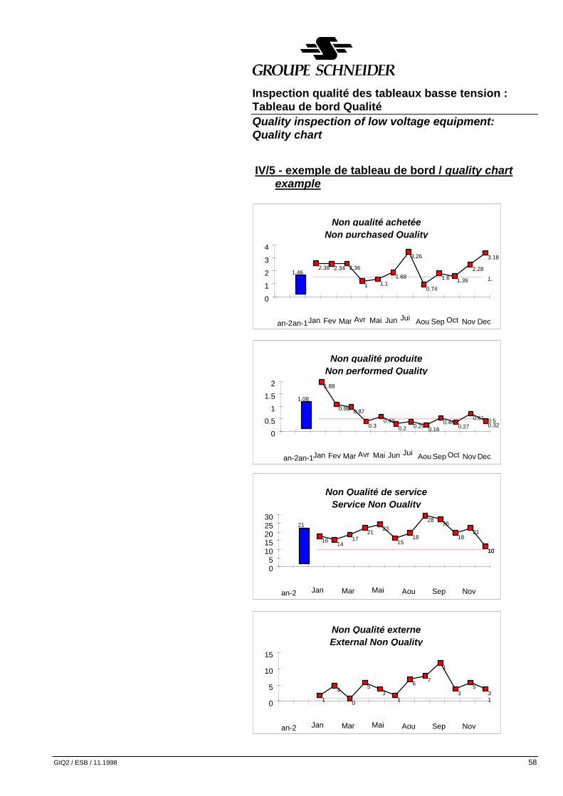
Inspection qualité des tableaux basse tension : Tableau de bord Qualité Quality inspection of low voltage equipment: Quality chart
GIQ2 / ESB / 11.1998 58
IV/5 - exemple de tableau de bord / quality chart example
Non qualité produiteNon performed Quality
1.08
1.88
0.98 0.87
0.30.49
0.2 0.29 0.160.44
0.270.61
0.320.5
0
0.5
1
1.5
2
an-2an-1Jan Fev Mar Avr Mai Jun Jui Aou Sep Oct Nov Dec
Non Qualité de serviceService Non Quality
21
1614
1721 23
1518
2826
1821
1010
05
1015202530
an-2 Jan Mar Mai Aou Sep Nov
Non Qualité externeExternal Non Quality
4
0
53
1
6 7
1
35
3110
5
10
15
an-2 Jan Mar Mai Aou Sep Nov
Non qualité achetéeNon purchased Quality
1.462.38 2.34 2.36
1 1.11.68
3.26
0.74
1.6 1.39
2.28
3.18
1.
0
1
2
3
4
an-2an-1Jan Fev Mar Avr Mai Jun Jui Aou Sep Oct Nov Dec

Inspection qualité des tableaux basse tension : Tableau de bord Qualité Quality inspection of low voltage equipment: Quality chart
GIQ2 / ESB / 11.1998 59
IV/6 - exemple de pondération des non conformités non conformity weight example
Item Description / Description
Poids / weight
1 2 3 4 5 6 7 8 9
10
11
12
13
14
15
16
17
18
19
20
Etiquette / Labelling Marquage filerie / Wire marking Aspect câblage / Wiring aspect Accessibilité des équipements / Accessibility of equipment Fixation des appareils / Fixation of apparatus Espace raccordement client / space for customer connection Mauvais sertissage / Bad crimping Calibre protection auxiliaires / Auxiliary protection rating Section filerie auxiliaire / Auxiliary wire section Respect IP / IP degree Connexion des masses / Earth connection Polarité des phases / Phase polarity Sequence de fonctionnement electrique / Electrical sequence operation Filerie auxiliaire endomagée / Auxiliary wire damages Câbles puissance endomagés / Power wire damages Distance d’isolement / Insulating distance Dimension des câbles ou JdB / Power cable or bus bars section Conformité des appareils de protection / Protection devices conformity Nombre et espacement des support de JdB / number and clearance of busbars supports Verrouillages / Interlockings
1 1 1 1 1 1 3 3 3 3 3 3 3 3
10
10
10
10
10
10

Appendix
GIQ2 / ESB / 11.1998 60
14. Glossary B.E.A.: Project Design Department B.M.A.: Project Methods Department B.N.M.: National Metrology Office. L.V.: Low Voltage. L.V.D.C.: Low Voltage Distribution Catalogue. I.E.C.: International Electrotechnical Commission. C.A.R.: Customer Acceptance Report. Dielectrimeter: A device used only to perform dielectric tests. Dielectrometer: A device used for dielectric testing. It measures insulation resistance and then dielectric withstand. H.B.C.: High Breaking Capacity. I.S.C.: Short Circuit-Current. I.P.: Degree of Protection. Q.I.: Quality Inspection. Q.I.: Quality Inspector. Megohmmeter: a device used to measure insulation. N.N.C.: Notification of Non Conformity. I.T.P.: Inspection and Test Programme. P.E.: Electrical Protection. P.E.N.: Electrical Protection with Neutral. C.T.: Current Transformer. S.E.: Sales Engineer.