Quality Connector for heavy duty multipole A perfect...
40
Quality Connector for .... A perfect Connection R heavy duty multipole Industrial Connectors
-
Upload
hoangthuan -
Category
Documents
-
view
215 -
download
2
Transcript of Quality Connector for heavy duty multipole A perfect...

Quality Connector for....
A perfect Connection
R
heavy duty multipole
Industrial Connectors

COMPANY PROFILE
Indo Electricals was established in the year 1975 at Vadodara India for manufacturing of Signaling and different terminals. Due to the change in market demand and change in market scenario since 1993 we started the manufacture of Industrial Connectors. This has now become our core competence.
Indo Electricals is one of the leading manufacturers of Industrial Connector in India. During the years the Company has undergone continuous modernization, for which we now have a versatile & sophisticated workshop that is under continuous upgradation. Connectors are designed using the state of art software and are developed in a well facilitated and sophisticated tool room equipped with the latest CNC machines for manufacturing & equipment for desired Quality Control.
To fulfill the market requirements the company has enhanced its new premises. The Companies objective is to continuously upgrade its manufacturing facility, improve its techniques, Automate the Production line to ensure a Quality product at the right time at the right place at the right cost.
At present throughout the electrical & electronic Industry wherever connection, interconnection system and solenoids are required and specifically where data processing control and measurement applications are involved, our products meet the most exacting requirement and are in daily use throughout the country in all the field of engineering. The Company has close link with leading OEM Companies resulting in innovation due to constant interaction, which has set current trends and have found country wide recognition.
The Company is catering to the highly technologically advanced domestic market of Switchgear Industries more then a decade & strives to meet the technical specification as per Industry requirement. It has also been regularly dealing with sophisticated Machinery Manufacturer of CNC Machines, Micro Process Plastic Injection Molding Machine, Textile, Automobile Assembly line, Robotic Equipment, SPM, Power Station, Electro Medical apparatus etc.
VISION
MISSION
indoelectricals.com

STANDARDS
ICO A
ICO AA
ICO AB
ICO ABS
ICO AQ
indoelectricals.comINDEX
6,8,10,16,24,32,32(2x16),48(2x24)+PE
6,10,16,24,32(2x16),48(2x24)+PE
6,10,16,24,32(2x16),48(2x24)+PE
10,18,32,46,64(32x2),92(46x2)+PE
5+PE
Screw Terminal
Screwless
Spring Terminal
Crimp Terminal
Crimp Terminal
Crimp Terminal
16A 500V
16A 500V
16A 500V
16A 500V
ICO B 6,12(6x2)+PEScrew Terminal 35A 690V
16A 400V
ICO E Screw Terminal 80A/16A 830V/400V
80A/16A 400V
4/0, 4/2+PE
4/8+PE
ICO ABE Crimp Terminal 16A 500V 40,64+PE
FPIU
Machine Lamp
ACCESSORIES
HOODS & HOUSINGS
ICO CA
ICO C
ICO D
ICO DD
3,4+PE
10,16,24,32(16x2),48(16x3),64(16x4),72(24x3)+PE
7,8,15,25,40,50(25x2),64,80(40x2),128(64x2)+PE
24,42,72,108,144(72x2),216(108x2)+PE
Screw Terminal
Screw Terminal
CrimpTerminal
Crimp Terminal
10A 400V
16A 250V
10A 250V
10A 250V
08-16
02-06
08-16
08-16
26-28
18-24
32-38
30-31
50-56
40-48
62-65
58-60
69
66-67
155-157
140-154
158-160
Page No.

2
Degrees of pollutionPollution indicates the presence of any kind of foreign matter, whether solid, liquid or gaseous (ionised gas) that can have a negative influence on the dielectric strength or on the surface resistivity of the insulating material.The standard establishes four degrees of pollution. The categories are identified by conventional numbers based on the quantity of polluting agents or on the frequency of the phenomenon which determines the reduction of the dielectric strength and/or of the surface resistivity.
Pollution degree 1:No pollution or only dry, non-conductive pollution.The pollution has no influence.Pollution degree 2:Only non-conductive pollution except that occasionally a temporary conductivity caused by condensation may occur.Pollution degree 3:Conductive pollution or dry, non-conductive pollution which becomes conductive due to condensation which may occur.Pollution degree 4:The pollution generates persistent conductivity caused by conductive dust or by rain or snow.
Pollution degree 3 is typical of an industrial environment or similar, while pollution degree 2 is typical of a household environment or similar.
Standard EN 61984 permits the sizing of surface insulation distances of connectors installed in enclosures in protection class &IP54 for the degree of pollution immediately below that of the application environment (e.g.: 2 instead of 3).
Extract from standard EN 619846.19.2.2 For a connector in protection class IP54 or higher, according to Publication IEC 60529, the insulating parts inside the enclosure may be sized for a lower degree of pollution.This applies also to coupled connectors, closure of which is ensured by the connector enclosure, and which may be uncoupled for test and maintenance purposes only.One may therefore use connectors installed in enclosures or containers in protection class & IP 54, at the rated data referring to degree pollution 2 in industrial applications with degree of pollution 3, if, in compliance with the standard, the coupling of the connectors is opened only occasionally for tests or maintenance. In the event of temporary or limited duration in uncoupled state, a closing cover is, however, necessary, guaranteeing at least protection class IP 54. However, this does not apply to connectors which remain uncoupled and exposed to an industrial atmosphere for an indefinite period. It should be noted, however, that pollution could penetrate inside coupled connectors, also when it comes from remote parts of the electrical system (e.g. through conduits providing cable entry to the connectors enclosure).Moreover, connector enclosures are usually supplied without cable entry devices, with the installer fitting such devices according to need. The degree of protection marked on the enclosures is guaranteed only for connectors coupled through the use of cable entry devices in equal or higher IP protection class and expertly installed.
Examples of application for the selection of degree of pollution 2 for a connector- connector on an electric motor controller, which is uncoupled only to replace a faulty motor, also in cases where degree of pollution 3 is instead specified for the system ;- connector on a module-constructed machine, which is opened only for transport purposes and which is used only for faster installation and for safer putting into service. One must make sure that the connector has not been polluted during transport. To ensure this has not occurred, protective covers or adequate packing must be used;- connector inside a panel in protection class &IP54. In this case one may even renounce equipping the connector with an IP54 enclosure.
Insulating materialInsulating material influences the determination of the minimum creepage distance. It is characterised according to the damage it suffers from the concentrated release of energy during scintillations when a surface leakage current is interrupted due to the drying of the contaminated surface.The CTI (comparative tracking index), (index of resistance to surface currents) is assumed as index of the resistance to creep currents of the insulating materials in the presence of atmospheric contaminating agents.The CTI constitutes the numeric value of the maximum voltage at which a material can resist against 50 drops of an electrolytic test solution without tracking, i.e. without a progressive formation of conductive paths on the surface of the solid insulating material (and permanent electric arc between the electrodes of the test equipment) due to the combined effect of electrical stress and electrolytic contamination.
The solid insulating materials are classified into four groups: Group I 600 < CTI Group II 400 < CTI < 600 Group Ilia 175 < CTI < 400 Group Illb 100 < CTI < 175
The values for groups Illa/lllb (Table 6, EN 61984) are identical for the purpose of determining the creepage distance values.The insulating materials used to manufacture the INDO ELECTRICALS multipole connectors belong to groups Ilia / Illb.
Dimensioning of clearances and creepage distancesEuropean standard EN 61984 Ed. 1.0 (22001-11) was recently published for safety prescriptions for multipole connectors for industrial uses and for the relevant tests. This standard assimilates, without any modifications, the corresponding international standard IEC 61984 Ed.1.0 (2001-06). It is applicable to connectors with rated voltage values of over 50V, and up to 1000V, and rated currents values of up to 125A per pole, for which no dedicated standard exists, or to which the particular specifications or the manufacturer refer as regards the safety aspects.For determining the minimum through-air and surface insulation distances, i.e. creepage distances, for connectors, this standard makes use (with some modifications) of the concepts of standard IEC 60664-1 Ed. 1.0 (1992-10)1'.NOTE - For connectors with rated voltage values of up to 50V - excluded from the field of application of Low Voltage Directive 73/23/EEC - standard EN 61984 may be used as a guide. For surface and through-air insulation distances, refer to standard IEC 60664-1 Ed. (1992-10).We are illustrating below the method of standard EN 61984 for determining minimum insulation values in connectors. The following are now obsolete: the insulation group concept, and the distinction of rated voltage values into d.c. and a.c. voltage values 220V and 380V were adapted to standardised values 230V and 400V according to IEC 60038'21 and some concepts were taken from the regulations for LV electrical systems of the IEC 60364'3' series, as follows:- The over voltage categories (I, II, III, IV), according to the use of the equipment<4). They are correlated to the transient over-voltages taken as a basis for determining the rated impulse withstand voltage- The degrees of pollution- The classification of insulating materials according to their resistance to tracking- The conditions of the electrical field (homogenous or inhomogenous).
Over voltage categories (or impulse withstand)The over voltage categories of a circuit or of an electrical system are identified by a conventional number (from I to IV) based on the limit or the control of the assumed transient over voltage values obtained on a circuit or electrical system and depends on the means used to reduce the over voltages.
TABLE 1The rated impulse withstand voltage for equipment energised directly from the low-voltage mains (IEC 60664-1 Edition 1.0 1992-10)
(a) The "/" symbol indicates a four-wire three phase distribution system (star distribution), The lower value is the voltage between phase and neutral (phase voltage), whereas the higher value is the voltage between the phases (mains voltage). Where only one value is indicated, it refers to three-wire, three-phase systems (delta distribution) and specifies the line-to-line value.(b) Equipment with these rated impulse withstand values can be used in installations in accordance with standard IEC 6036+4-443 (Italian standard CEI 64W4 Section 443, German standard DIN VDE 0100-443).
Table 1 supplies the rated impulse withstand voltage for equipment energised directly from the low voltage mains in function of the rated voltage of the power supply system, the relative voltage line-to-neutral and the over voltage category. Industrial machinery and installations with fixed connection to the low voltage supply system and consequently the relative components including multipole connectors, constitute an example of the equipment that belongs to the over voltage category III.Examples of general equipment that comes under over voltage category II are electrical household appliances, portable tools and other household equipment or similar.For distribution networks with rated voltage of 230/400V (star distribution with earthed neutral), and over-voltage category III (category III: impulse withstanding), the demanded rated impulse withstanding voltage is 4kV.For distribution networks with rated voltage of 400 or 500V (star distribution without neutral or with insulated neutral, or delta distribution, insulated or corner-earthed), and over-voltage category III (category III: impulse withstanding), the demanded rated impulse withstanding voltage is 6kV.
(1) Assimilated with modifications as European Harmonisation Document HD 625.1 S1:1996 and published by the CENELEC member countries as a national standard: Italian standard CEI 28-6 (1997-11), German standard DIN VDE 0110-1 (VDE 0110Teil 1):1997-04. (2) Harminisation Document CENELEC HD 472 S1, Italian standard CEI 8-6, German standard DIN IEC 38:1987-05. (3) Italian standard CEI 64-8, German standard DIN VDE 0100. (4) HD 625.1 S1 modifies the definition to "impulse withstanding categories".
Nominal voltage of Voltage line to netural Rated impulse withstandb)the supply system derived from nominal voltage
based on IEC 60038 voltage a.c. or d.c.(CENELEC HD 472 S1, CEI 8-6) Over Voltage categoryV V < V V
a)Three phase Single phase I II III IV
50 330 500 800 1500 100 500 800 1500 2500 120-240 150 800 1500 2500 4000230/400 300 1500 2500 4000 6000277/480400/690 600 2500 4000 6000 80001000 1000 4000 6000 8000 12000
indoelectricals.comSTANDARDS

Electric field conditionsThe insulation clearance is determined in Table 2 of IEC 60664-1, bearing in mind the following influencing factors:- Rated impulse withstand voltage- Electric field conditions- Altitude: the values specified in Table 2 give sufficient impulse withstand capability for equipment for use at altitudes up to 2.000 m. For equipment for use at higher altitudes, the corrective factors specified in Table A2 of IEC 60664-1- The micro-environment. The shape and arrangement of the conductive parts influence the homogeneity of the electric field and consequently the clearance needed to withstand a given voltage. The clearances in Case A (inhomogeneous field) have the required impulse withstand voltage under all conditions: clearances not less than those specified in Table 2 - Case A can be used irrespective of the shape and arrangement of the conductive parts and without verification by an impulse withstand test.
Determination of clearancesIn accordance with standard IEC 60664-1, the following must be identified to determine it:(a) The rated voltage of the power supply (usually 230/400V and therefore a conventional voltage line-to-neutral of 300V), in star distribution networks with earthed neutral, or 400V for star networks without neutral, or with insulated neutral, or in networks with the distribution transformer's secondary winding delta connected, insulated or corner-earthed and, therefore, with conventional phase voltage of 600V);(b) The overvoltage category (usually III);(c) The rated impulse withstand voltage determined from Table 1 of IEC 606641 (usually 4 kV or 6kV)(d) The type of electric field to which the parts through which the current flows shall be subjected (worse case = inhomogenous field) and the degree of pollution (usually 3).Standard EN 61984 specifies that the through-air insulation distance should be sized according to Table 2 of IEC 60664-1, but according to the rated impulse withstanding voltage obtained from Table 5 of EN 61984. The rated impulse withstanding voltage must be selected according to the rated power supply voltage and to the overvoltage category. The assignment of connectors to a particular overvoltage category (usually III) is effected according to the rules of IEC 60664-1.
Rated voltageThe voltage value assigned by the manufacturer to the connector and to which the operating and performance characteristics refer (IEC 60664-1, definition 1.3.9 modified).NOTE - A connector may have more than one rated voltage value. As concerns the choice of the type of electric field, the through-air insulation distances via windows and openings in the enclosures of insulating material, must comply with the values of case A in Table of IEC 60664-1. i.e. for non uniform field conditions.
TABLE 5Rated impulse withstand voltage (EN 61984 Edition 1.0 - 2001-11)
1) Between pointed and flat electrode.2) When the clearance is less than the value indicated for Case A an impulse withstand voltage test certificate is required3) Preferential values specified in Table 14) For printed wiring material, the values of degree of pollution 1 apply except that the value shall not be less than 0.04 mm as specified in Table 45) These minimum clearances given for pollution degrees 2, 3 and 4 are based on experience rather than on fundamental data.*) Table 2 of IEC 60664-1 is modified in Variant 2. In particular, the columns referring to degree of pollution 4 have been eliminated. The definition of this degree is varied in 2.5.1 to: "permanent conductivity occurs, due to conductive dust, rain or other humid conditions". The through-air insulation distances for degree of pollution 4 area as specified for degree of pollution 3, with the exception that the minimum through air distance is 1.6 mm. In 2.5.2 it is specified that "in conductive pollution conditions, the dimensions for the surface insulation distances cannot be specified where permanent conductive pollution is present, e.g.: due to coal or metal dust. On the contrary, the insulation surface should be designed in order to prevent a seamless path of conductive pollution, e.g.: by means of ribs and cavities".The values written in bold are the most common multipole connectors for industrial purposes.If the component respects the minimum through-air insulation distance prescribed for live parts of opposing polarities, it is exempted from the impulsed voltage withstanding test. This test is run at sea level using increased voltage values in order to take into account rarefied air at high altitude (the prescribed values refer to 2000 m asl. However, if this distance is not respected, passing the test gives one the right to declare the relevant rated impulse withstanding voltage.Declaration of the rated impulse withstanding voltage is optional for standard EN 61984: if the manufacturer declares the rated impulse withstanding voltage, the impulse withstanding voltage test is, in any event, necessary as dielectric verification. Alternatively, if the manufacturer does not declare this rated value, the voltage withstanding dielectric test at mains frequencies of 50/60 Hz for 60 s (test 4a of IEC 60512) is necessary but at reduced values compared to the peak values of the impulsive test voltages of wave shape standardised at 1.2/50 us. To this end, standard EN 61984 provides the following cross-reference table:
TABLE 8Test voltages (EN61984 Edition 1.0 - 2001-11)
* If the test laboratory is situated between sea level and an altitude of 2000 m asl, interpolation of test impulsed voltage is allowed.
Rated impulse withstand voltageThe rated impulse withstanding voltage assigned by the manufacturer to the connector, which refers to the withstanding capacity of its insulation with respect to transient overvoltages [IEC 60664-1, definition 1.3.9.2 modified].Impulse withstand voltageThe highest peak value of a voltage impulse of prescribed shape and polarity, which does not cause insulation faults under specified conditions.
Rated impulse Test voltages withstand voltage impulse withstand* withstand voltage kV voltage (r.m.s. value) kV (1.2/50 us) kV (50/60 Hz) at 2000 above sea level at sea level
0.33 0.33 0.35 0.23 0.5 0.5 0.55 0.37 0.8 0.8 0.91 0.50 1.5 1.5 1.75 0.84 2.5 2.5 2.95 1.39 4 4 4.8 1.21 6 6 7.3 3.31 8 8 9.8 4.26 12 12 14.8 6.6
kV 1 2 3 4 1 2 3 43) 4) 5) 5) 5) 4) 5) 5) 5) 0.33 0.01 0.2 0.8 1.6 0.01 0.2 0.8 1.6
4) 5) 5) 5) 4) 5) 5) 5) 0.40 0.02 0.2 0.8 1.6 0.02 0.2 0.8 1.6 3) 4) 5) 5) 5) 4) 5) 5) 5)0.50 0.04 0.2 0.8 1.6 0.04 0.2 0.8 1.6 4) 5) 5) 5) 4) 5) 5) 5)0.60 0.06 0.2 0.8 1.6 0.06 0.2 0.8 1.6
3) 4) 5) 5) 5) 4) 5) 5) 5) 0.80 0.10 0.2 0.8 1.6 0.10 0.2 0.8 1.6 4) 5) 5) 5) 4) 5) 5) 5)1.0 0.15 0.2 0.8 1.6 0.15 0.2 0.8 1.6 5) 5) 4) 5) 5) 5)1.2 0.25 0.25 0.8 1.6 0.2 0.2 0.8 1.6 3) 4) 5) 5) 5) 5) 5)1.5 0.05 0.2 0.8 1.6 0.3 0.3 0.8 1.6 4) 5) 5) 5) 5)2.0 1.0 0.2 1.0 1.6 0.45 0.45 0.8 1.6 3) 4) 5) 5) 5) 5)2.5 1.5 0.2 1.5 1.6 0.6 0.6 0.8 1.6 5) 5)3.0 2 2 2 2 0.8 0.8 0.8 1.6 3) 5)4.0 3 3 3 3 1.2 1.2 1.2 1.6 5)5.0 4 4 4 4 1.5 1.5 1.5 1.6
3) 6.0 5.5 5.5 5.5 5.5 2 2 2 2 3) 8.0 8 8 8 8 3 3 3 3
10.0 11 11 11 11 3.5 3.5 3.5 3.5 3) 12.0 14 14 14 14 4.5 4.5 4.5 4.5
Requiredimpulsewithstandvoltage
Minimum clearances in air in mm.up to 2.000 m. above sea level
Case A - inhomogenous field 1) Case B - inhomogenous field 2)
degree of pollution degree of pollution
TABLE 8Minimum clearance for insulation co-ordination (IEC 60664-1 Edition 1.0 - 1992-10)
With the three values (b) (c) and (d) the minium clearence is determined in Table 2 of IEC 60664-1
Vol
tage
line
-to-
eart
h de
rived
from
the
nim
inal
vol
tage
of t
hesu
pply
sys
tem
to th
e a.
c. v
olta
ge(r
.m.s
. val
ue)
or d
.c. v
olta
ge
Spe
cial
pro
tect
ed le
vels
Leve
l for
ele
ctric
al e
quip
men
t(h
ouse
hold
and
sim
ilar)
Leve
l for
dis
trib
utio
nsu
pply
sys
tem
s
Inpu
t lev
el
Nominal voltage of the supply system
(< rated insulation voltage of equipment)
Preferred values for the rated impluse withstand voltage in kV (1.2/50 us)
Over voltage category
I II III IV a.c. a.c. a.c. a.c. voltage voltage voltage voltage (r.m.s. (r.m.s. (r.m.s. (r.m.s. value) value) value) value) d.c. d.c. voltage voltage
V V V V V kV kV kV kV 100 66/115 66 60 - 0.5 0.8 1.5 2.5 150 120/208; 115;120; 110; 120; 220-110; 0.8 1.5 2.5 4 127/220; 127 240-120; 300 220/380; 220; 230; 220 440-220 1.5 2.5 4 6 230/400; 240; 260; 240/415; 277; 260/440; 277/480; 600 347/600; 347; 380; 480 960-480 2.5 4 6 8 380/660 400; 145; 400/690 440; 480; 415/720 500; 480; 480/830 600; 1000 660; 690; 1000 - 4 6 8 12 720; 830; 1000; * Value for voltage , 50V mentioned in IEC 60664-1, Encl. B
indoelectricals.comSTANDARDS
3

With this voltage value, the pollution degree and the materials group the minimum creepage distance can be determined using Table 6.
NOTE 1: The values for voltages s 50V are supplied in IEC 60664-1, Table 4.NOTE 2: The values in bold are reduced compared to those of Table 4 IEC 60664-1, in compliance with 2.4 of IEC 60664-1.a Materials group I or materials group II, III, where the possibility of tracking is reduced in conformance with the conditions of paragraph 3.2 of IEC 60664-1.b Materials group I, II, Ilia, Illbc Materials group Illb is not recommended for application with pollution degree 3 above 630V and with pollution degree 4.
Legends :A = All systems.B = Single phase three-wire systems with mid-point earthed.C = Three-phase four-wire systems [secondary winding of a star distribution transformer] neutral-earthed2).D = Three-phase three-wire systems [secondary winding of a delta distribution transformer], unearthed " or corner-earthed.
(1) The phase-earth insulation for unearthed or impedance-earthed lines is equal to that between phases, because the operating voltage of any phase can, in practice, approach full voltage between the phases [line voltage]. This is because the actual voltage to earth is determined by the insulation resistance and by the capacitive reactance of each phase to earth. Consequently, a low (but acceptable) insulation resistance of a phase can, in effect, earth it and increase voltage to earth of the other two phases at full voltage between the phases [line voltage].(2) For equipment for use on both three-phase three-wire and three-phase four wire supplies, earthed or unearthed, use only the values for three-wire systems. (*) Assuming a rated voltage of the equipment.(**) These values correspond to the values given in Table 1.
Dimensioning of creepage distances
The minimum surface insulation distance (creepage distance), i.e. "the shortest distance along the surface of the insulation material between two conducting parts " [IE 60664-1 development 1.3.3] for connectors is prescribed by standard EN 61984 in Table 6. It is determined according to rated voltage, degree of pollution and insulating material group. The rated voltage providing access to Table 6 (rationalised voltage of the feed system) is determined in Table 3a of IEC 60664-1 for single phase two or three wire a.c. or d.c. systems or Table 3b for three-phase three or four wire a.c. systems. Usually for three-phase systems with 230V/400V reted voltage, the conventional line-to-line insulation voltage is 400V and the line-to-earth for TT or TN systems is 250V. For three-phase systems with 400V or 500V rated voltage the conventional line-to-line insulation voltage is respectively 400V and 500V.The degree of pollution must be specified according to standard IEC 60664-1. It strongly influences the rated insulation voltage of a connector. Therefore, the rated insulation voltage of a connector should be reconsidered time by time for each degree of pollution.
Table 6Minimum creepage distance (EN 61984 Edition 1.0 - 2001-11)
Rated
voltage
r.m.s. value
a.c. or d.c.a c c V I II III I II III I II III
63 0.2 0.63 0.9 1.25 1.6 1.8 2 2.1 2.6 3.4
80 0.22 0.67 0.95 1.3 1.7 1.9 2.1 2.2 2.8 3.6
100 0.25 0.71 1 1.4 1.8 2 2.2 2.4 3 3.8
125 0.28 0.75 1.05 1.5 1.9 2.1 2.4 2.5 3.2 4
160 0.32 0.8 1.1 1.6 2 2.2 2.5 3.2 4 5
200 0.42 1 1.4 2 2.5 2.8 3.2 4 5 6.3
250 0.56 1.25 1.8 2.5 3 3.5 4 5 6.3 7.5
320 0.75 1.6 2.2 3.2 4 4.5 5 6 7.3 8.6
400 1 2 2.8 4 4.5 5.3 6 7 8.5 10
500 1.3 2.5 3.6 5 6 7 8 9 11 13
630 1.8 3.2 4.5 6.3 8 9 10 11.1 13.6 16.1
800 2.4 4 5.6 8 9 10.5 12 13.8 17 20.2
1000 3.2 5 7.1 10 12 14 16 17 21 25
Minimum creepage distances (mm)
Pollution degree
1 2 3 4bsee note Material group material group Material group
TABLE 3aSingle phase two or three wire a.c. or d.c. systems (IEC 60664-1 Edition 1.0 - 1992-10)
TABLE 3bThree-phase three or four wire a.c. systems (IEC 60664-1 Edition 1.0 - 1992-10)
Nom
inal
volta
ge o
f the
supp
ly s
yste
m*) Voltage rationalised
for Table 4
for insulation1)line-to-line
A
1)line-to-earth
B
V V V
12.5 12.5 -
24 25 -
25 25 -
30 32 -
42 50 -
48 50 -
50** 50 -
60 63 -
30-60 63 32
100** 100 -
110 125 -
120 125 -
150** 160 -
220 250 -
110-220 250 125
120-240 250 125
300** 320 -
220-440 500 250
600** 630 -
480-960 1000 500
1000** 1000 -
Nom
inal
volta
ge o
f the
supp
ly s
yste
m*) Voltage rationalised
for Table 4
for insulation1)line-to-line
A C
1)line-to-earth D
V V V V 63 63 32 63 110 125 80 125 120 125 80 125 127 125 80 125 150** 160 - 160 208 200 125 200 220 250 160 250 230 250 160 250 240 250 160 250 300** 320 - 320 380 400 250 400 400 400 250 400 415 400 250 400 440 500 250 500 480 500 320 500 500 500 320 500 575 630 400 630 600** 630 - 630 660 630 400 630 690 630 400 630 720 800 500 800 830 800 500 800 960 1000 630 1000 1000** 1000 - 1000
indoelectricals.comSTANDARDS
4
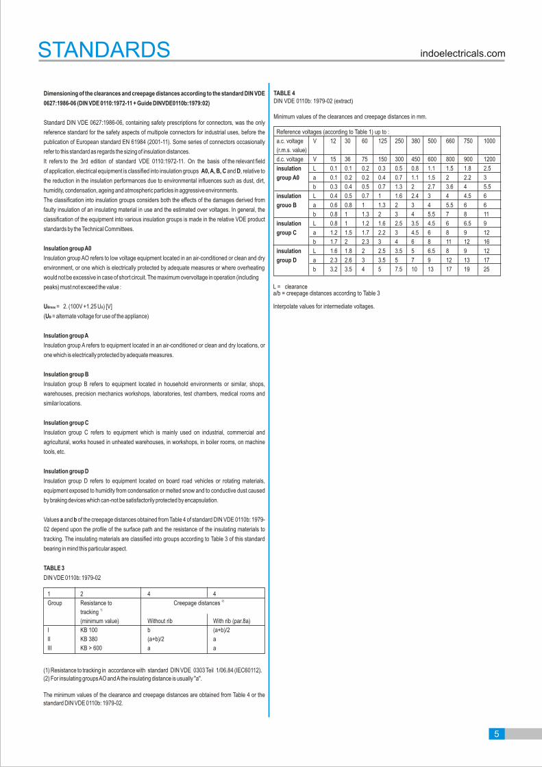
Dimensioning of the clearances and creepage distances according to the standard DIN VDE
0627:1986-06 (DIN VDE 0110:1972-11 + Guide DINVDE0110b:1979:02)
Standard DIN VDE 0627:1986-06, containing safety prescriptions for connectors, was the only
reference standard for the safety aspects of multipole connectors for industrial uses, before the
publication of European standard EN 61984 (2001-11). Some series of connectors occasionally
refer to this standard as regards the sizing of insulation distances.
It refers to the 3rd edition of standard VDE 0110:1972-11. On the basis of the relevant field
of application, electrical equipment is classified into insulation groups A0, A, B, C and D, relative to
the reduction in the insulation performances due to environmental influences such as dust, dirt,
humidity, condensation, ageing and atmospheric particles in aggressive environments.
The classification into insulation groups considers both the effects of the damages derived from
faulty insulation of an insulating material in use and the estimated over voltages. In general, the
classification of the equipment into various insulation groups is made in the relative VDE product
standards by the Technical Committees.
Insulation group A0
Insulation group AO refers to low voltage equipment located in an air-conditioned or clean and dry
environment, or one which is electrically protected by adequate measures or where overheating
would not be excessive in case of short circuit. The maximum overvoltage in operation (including
peaks) must not exceed the value :
UBmax = 2. (100V +1.25 UB) [V]
(UB = alternate voltage for use of the appliance)
Insulation group A
Insulation group A refers to equipment located in an air-conditioned or clean and dry locations, or
one which is electrically protected by adequate measures.
Insulation group B
Insulation group B refers to equipment located in household environments or similar, shops,
warehouses, precision mechanics workshops, laboratories, test chambers, medical rooms and
similar locations.
Insulation group C
Insulation group C refers to equipment which is mainly used on industrial, commercial and
agricultural, works housed in unheated warehouses, in workshops, in boiler rooms, on machine
tools, etc.
Insulation group D
Insulation group D refers to equipment located on board road vehicles or rotating materials,
equipment exposed to humidity from condensation or melted snow and to conductive dust caused
by braking devices which can-not be satisfactorily protected by encapsulation.
Values a and b of the creepage distances obtained from Table 4 of standard DIN VDE 0110b: 1979-
02 depend upon the profile of the surface path and the resistance of the insulating materials to
tracking. The insulating materials are classified into groups according to Table 3 of this standard
bearing in mind this particular aspect.
TABLE 3
DIN VDE 0110b: 1979-02
(1) Resistance to tracking in accordance with standard DIN VDE 0303 Teil 1/06.84 (IEC60112).
(2) For insulating groups AO and A the insulating distance is usually "a".
The minimum values of the clearance and creepage distances are obtained from Table 4 or the
standard DIN VDE 0110b: 1979-02.
1 2 4 42)Group Resistance to Creepage distances
1) tracking
(minimum value) Without rib With rib (par.8a)
I KB 100 b (a+b)/2
II KB 380 (a+b)/2 a
III KB > 600 a a
TABLE 4DIN VDE 0110b: 1979-02 (extract)
Minimum values of the clearances and creepage distances in mm.
Reference voltages (according to Table 1) up to :
a.c. voltage V 12 30 60 125 250 380 500 660 750 1000
(r.m.s. value)
d.c. voltage V 15 36 75 150 300 450 600 800 900 1200
insulation L 0.1 0.1 0.2 0.3 0.5 0.8 1.1 1.5 1.8 2.5
group A0 a 0.1 0.2 0.2 0.4 0.7 1.1 1.5 2 2.2 3
b 0.3 0.4 0.5 0.7 1.3 2 2.7 3.6 4 5.5
insulation L 0.4 0.5 0.7 1 1.6 2.4 3 4 4.5 6
grouo B a 0.6 0.8 1 1.3 2 3 4 5.5 6 6
b 0.8 1 1.3 2 3 4 5.5 7 8 11
insulation L 0.8 1 1.2 1.6 2.5 3.5 4.5 6 6.5 9
group C a 1.2 1.5 1.7 2.2 3 4.5 6 8 9 12
b 1.7 2 2.3 3 4 6 8 11 12 16
insulation L 1.6 1.8 2 2.5 3.5 5 6.5 8 9 12
group D a 2.3 2.6 3 3.5 5 7 9 12 13 17
b 3.2 3.5 4 5 7.5 10 13 17 19 25
L = clearancea/b = creepage distances according to Table 3
Interpolate values for intermediate voltages.
indoelectricals.comSTANDARDS
5

01 1 0 016 M 0 1 1
Type of Connector
Range of Connector
Colour of connector
No. of Contacts
Type of Insert
Sequence of Contact Numbers
Type of Termination
Surface Coating
01 9 1 016 B C 1 0
Type of Connector
Environmental Condition
Hood with respect to connector
No. of Contacts
Type of Construction of Casting
Type of Cable Entry
Type of Clamp
Type of Threads
01 9 1 016 PM 40
Type of Connector
Type of Environmental Condition
Housing with respect to connector
No. of Contacts
Type of Mounting
Type of Clamp
01 9 1 016 B E 1 0
Type of Connector
Type of Environmental Condition
Housing with respect to connector
No. of Contacts
Type of Construction
Type of Entry
Type of Clamp
Type of Thread
CODING FOR INSERT
CODING FOR HOOD
CODING FOR BULKHEAD MOUNTING HOUSING
CODING FOR SURFACE MOUNTING HOUSING
indoelectricals.comCODING SYSTEM
6

indoelectricals.com
7

ICO A, ICO AA, ICO AB
indoelectricals.comICO A, ICO AA, ICO AB
Ambient temperature [ ]oC
Wo
rkin
g c
urr
en
t [A
]1. ICO A-0062. ICO A-0103. ICO A-0164. ICO A-024
Ambient temperature [ ]oC
Wo
rkin
g c
urr
en
t [A
]
1. ICO AA-0062. ICO AA-0103. ICO AA-0164. ICO AA-024
Ambient temperature [ ]oC
Wo
rkin
g c
urr
en
t [A
]
1. ICO AB-0062. ICO AB-0103. ICO AB-0164. ICO AB-024
Current carrying capacity
The current carrying is limited by maximum temperature of materials for inserts for inserts and contacts including terminals
Control and test procedures according to DIN EN 60512-5
TECHNICAL CHARACTERISTICS
8

Number of Contact
6+
Identification Series Drawing Dimension in mm. Male Female
0110 006 F0110110 006 M011
Contact arrangementview from termination side
35
36
44
27
3.3 O
Panel cut out forInsert without Housing/Hood
14
F
6 3
4
5
1
2
M
3 6
41
52
Rating : 16 A-500 V
Screw Terminal
Screwless Spring Terminal
Crimp Terminal
0110 006 F031
0110 006 F021
0110 006 M031
0110 006 M021
9
ICO A
ICO AA
ICO AB
ICO A, ICO AA, ICO AB
Crimp Contacts
0103 000 5M040103 000 5M030103 000 5M050103 000 5M020103 000 5M010103 000 5M060103 000 5M070103 000 5M08
Silver plated
Gold plated
0.14-0.370.500.751.001.502.503.004.00
0103 000 5F040103 000 5F030103 000 5F050103 000 5F020103 000 5F010103 000 5F060103 000 5F070103 000 5F08
0103 000 5M140103 000 5M130103 000 5M150103 000 5M120103 000 5M110103 000 5M160103 000 5M170103 000 5M18
0.14-0.370.500.751.001.502.503.004.00
0103 000 5F140103 000 5F130103 000 5F150103 000 5F120103 000 5F110103 000 5F160103 000 5F170103 000 5F18For crimping tool & contact removal tool Page No. 140
Identification Drawing Dimension in mm.2(mm ) Male Female
M3 X 10
51
34
34
44
27
M3 X 10
51
32
34
44 27
For Hoods/Housing please refer page no.91-96
22.20
7.50
Ø4.50
25.00
7.50
Ø4.50 Ø2.50
Wire gauge Striping length2
0.14-0.37 mm2
0.50 mm2
0.75 mm2
1.00 mm2
1.50 mm2
2.50 mm2
3.00 mm2
4.00 mm
7.5 mm7.5 mm7.5 mm7.5 mm7.5 mm7.5 mm7.5 mm7.5 mm
AWG 26-22AWG 20AWG 18AWG 18AWG 16AWG 14AWG 12AWG 12
Indentification
No GrooveNo Groove1 Groove1 Groove2 Groove3 Groove
Wide GrooveNo Groove
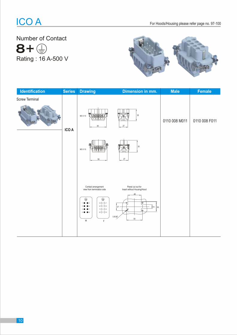
Number of Contact
8+
Identification Series Drawing Dimension in mm. Male Female
0110 008 F0110110 008 M011
Rating : 16 A-500 V
2
3
4
1
8
6
7
5
8
6
7
5
2
3
4
1
Panel cut out forInsert without Housing/Hood
Contact arrangementview from termination side
48
36
50
27
3.30 O
M F
Screw Terminal
2750
35
M3 X 10
M3 X 10
2750
35
ICO A
ICO A
14
10
For Hoods/Housing please refer page no. 97-100

Number of Contact
10+
0110 010 F0110110 010 M011
Panel cut out forInsert without Housing/Hood
Contact arrangementview from termination side
57
36
48
27
3.3 O105
94
83
61
72
10 5
9 4
8 3
16
27
Rating : 16 A-500 V
M F
Screw Terminal
0110 010 F031
0110 010 F021
0110 010 M031
0110 010 M021
Screwless Spring Terminal
Crimp Terminal
11
Identification Series Drawing Dimension in mm. Male Female
ICO A
ICO AA
ICO AB
ICO A, ICO AA, ICO AB
M3 X 10
64 34
34
5727
M3 X 10
64
32
57 27
34
14
Crimp Contacts
0103 000 5M040103 000 5M030103 000 5M050103 000 5M020103 000 5M010103 000 5M060103 000 5M070103 000 5M08
Silver plated
Gold plated
0.14-0.370.500.751.001.502.503.004.00
0103 000 5F040103 000 5F030103 000 5F050103 000 5F020103 000 5F010103 000 5F060103 000 5F070103 000 5F08
0103 000 5M140103 000 5M130103 000 5M150103 000 5M120103 000 5M110103 000 5M160103 000 5M170103 000 5M18
0.14-0.370.500.751.001.502.503.004.00
0103 000 5F140103 000 5F130103 000 5F150103 000 5F120103 000 5F110103 000 5F160103 000 5F170103 000 5F18
Identification Drawing Dimension in mm.2(mm ) Male Female
For Hoods/Housing please refer page no. 101-110
22.20
7.50
Ø4.50
25.00
7.50
Ø4.50 Ø2.50
Wire gauge Striping length2
0.14-0.37 mm2
0.50 mm2
0.75 mm2
1.00 mm2
1.50 mm2
2.50 mm2
3.00 mm2
4.00 mm
7.5 mm7.5 mm7.5 mm7.5 mm7.5 mm7.5 mm7.5 mm7.5 mm
AWG 26-22AWG 20AWG 18AWG 18AWG 16AWG 14AWG 12AWG 12
Indentification
No GrooveNo Groove1 Groove1 Groove2 Groove3 Groove
Wide GrooveNo Groove
For crimping tool & contact removal tool Page No. 140

Number of Contact
16+
0110 016 F0110110 016 M011
Contact arrangementview from termination side
Panel cut out forInsert without Housing/Hood
36
68.5
27
3.3 O
77.5
Rating : 16 A-500 V
M F
513135
15157
8 1616
14146
7
8
6
4 1212
3 1111
2 1010
4
3
2
1 99 1
Screw Terminal
0110 016 F031
0110 016 F021
0110 016 M031
0110 016 M021
Screwless Spring Terminal
Crimp Terminal
Identification Series Drawing Dimension in mm. Male Female
ICO A
ICO AA
ICO AB
ICO A, ICO AA, ICO AB
M3 X 10
84 34
3535
77.527
M3 X 10
84 34
77.5
33
27
Crimp Contacts
0103 000 5M040103 000 5M030103 000 5M050103 000 5M020103 000 5M010103 000 5M060103 000 5M070103 000 5M08
Silver plated
Gold plated
0.14-0.370.500.751.001.502.503.004.00
0103 000 5F040103 000 5F030103 000 5F050103 000 5F020103 000 5F010103 000 5F060103 000 5F070103 000 5F08
0103 000 5M140103 000 5M130103 000 5M150103 000 5M120103 000 5M110103 000 5M160103 000 5M170103 000 5M18
0.14-0.370.500.751.001.502.503.004.00
0103 000 5F140103 000 5F130103 000 5F150103 000 5F120103 000 5F110103 000 5F160103 000 5F170103 000 5F18
Identification Drawing Dimension in mm.2(mm ) Male Female
14
12
For Hoods/Housing please refer page no. 111-120
22.20
7.50
Ø4.50
25.00
7.50
Ø4.50 Ø2.50
Wire gauge Striping length2
0.14-0.37 mm2
0.50 mm2
0.75 mm2
1.00 mm2
1.50 mm2
2.50 mm2
3.00 mm2
4.00 mm
7.5 mm7.5 mm7.5 mm7.5 mm7.5 mm7.5 mm7.5 mm7.5 mm
AWG 26-22AWG 20AWG 18AWG 18AWG 16AWG 14AWG 12AWG 12
Indentification
No GrooveNo Groove1 Groove1 Groove2 Groove3 Groove
Wide GrooveNo Groove
For crimping tool & contact removal tool Page No. 140

Number of Contact
24+
0110 024 F0110110 024 M011
Panel cut out forInsert without Housing/Hood
Contact arrangementview from termination side
104
36
95
27
3.30 O9
8
11
10
12
2311
12 24
219
10 22
8 20
23
24
21
22
20
1
2
4
5
6
3
7
164
7 19
6 18
5 17
3 15
2 14
1 13
16
19
18
17
15
14
13
Rating : 16 A-500 V
M F
Screw Terminal
0110 024 F031
0110 024 F021
0110 024 M031
0110 024 M021
Screwless Spring Terminal
Crimp Terminal
13
Identification Series Drawing Dimension in mm. Male Female
ICO A
ICO AA
ICO AB
ICO A, ICO AA, ICO AB
M3 X 10
111 34
34
27104
M3 X 10
11134
104 27
32
14
Crimp Contacts
0103 000 5M040103 000 5M030103 000 5M050103 000 5M020103 000 5M010103 000 5M060103 000 5M070103 000 5M08
Silver plated
Gold plated
0.14-0.370.500.751.001.502.503.004.00
0103 000 5F040103 000 5F030103 000 5F050103 000 5F020103 000 5F010103 000 5F060103 000 5F070103 000 5F08
0103 000 5M140103 000 5M130103 000 5M150103 000 5M120103 000 5M110103 000 5M160103 000 5M170103 000 5M18
0.14-0.370.500.751.001.502.503.004.00
0103 000 5F140103 000 5F130103 000 5F150103 000 5F120103 000 5F110103 000 5F160103 000 5F170103 000 5F18
Identification Drawing Dimension in mm.2(mm ) Male Female
For Hoods/Housing please refer page no. 121-130
22.20
7.50
Ø4.50
25.00
7.50
Ø4.50 Ø2.50
Wire gauge Striping length2
0.14-0.37 mm2
0.50 mm2
0.75 mm2
1.00 mm2
1.50 mm2
2.50 mm2
3.00 mm2
4.00 mm
7.5 mm7.5 mm7.5 mm7.5 mm7.5 mm7.5 mm7.5 mm7.5 mm
AWG 26-22AWG 20AWG 18AWG 18AWG 16AWG 14AWG 12AWG 12
Indentification
No GrooveNo Groove1 Groove1 Groove2 Groove3 Groove
Wide GrooveNo Groove
For crimping tool & contact removal tool Page No. 140
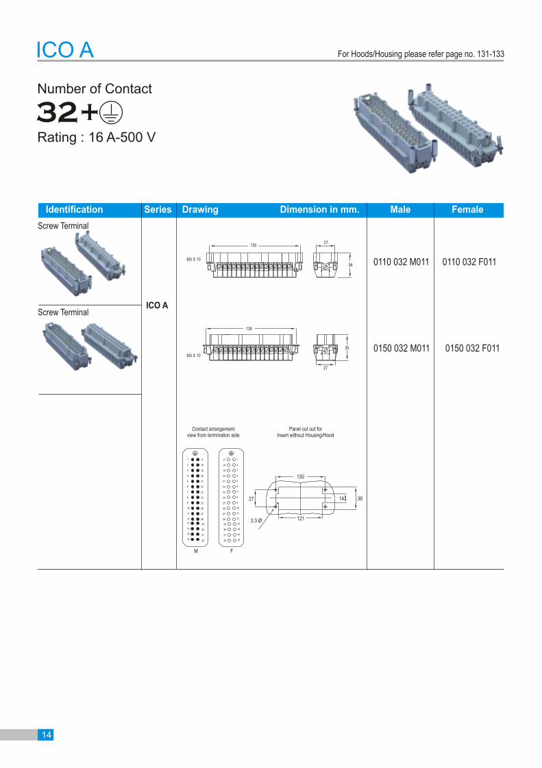
Number of Contact
32+
0110 032 M011
Contact arrangementview from termination side
Panel cut out forInsert without Housing/Hood
36
121
27
3.3 O
130
Rating : 16 A-500 V
14
10
12
11
8
9
7
5
6
3
4
1
2
23
24
26
25
28
27
10
12
11
9
7
8
17
18
19
21
22
20
3
6
5
4
1
2
16
15
13
14
31
32
30
29
16
15
13
14
M F
23
24
26
25
28
27
17
18
19
21
22
20
31
32
30
29
M3 X 10
13027
36
M3 X 10
27
35
ICO A
0110 032 F011
0150 032 F0110150 032 M011
Identification Series Drawing Dimension in mm. Male Female
ICO A
Screw Terminal
Screw Terminal
130
14
For Hoods/Housing please refer page no. 131-133
Screwless Spring Terminal
Crimp Terminal
Number of Contact
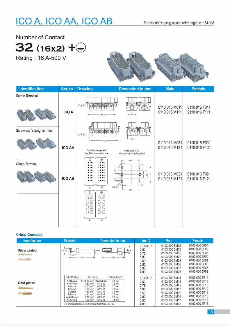
32 (16x2) +
Panel cut out forInsert without Housing/Hood
Contact arrangementview from termination side
35
68.5
27
3.30 O
14
77.5
71
0110 016 F0110110 016 F111
0110 016 M0110110 016 M111
Rating : 16 A-500 V
M M
F F
10 21826
2618102
3123157
328 16 24
146 3022
15 72331
81632 24
2230 14 6
135 2921
124 2820
113 2719
2129 13 5
2028 412
27 19 11 3
259 171
9 125 17
77.5
M3 X 10
77.5
M3 X 10
0110 016 F0310110 016 F131
0110 016 M0310110 016 M131
0110 016 F0210110 016 F121
0110 016 M0210110 016 M121
ICO A, ICO AA, ICO AB
15
ICO A
ICO AA
ICO AB
Identification Series Drawing Dimension in mm. Male Female
Crimp Contacts
0103 000 5M040103 000 5M030103 000 5M050103 000 5M020103 000 5M010103 000 5M060103 000 5M070103 000 5M08
Silver plated
Gold plated
0.14-0.370.500.751.001.502.503.004.00
0103 000 5F040103 000 5F030103 000 5F050103 000 5F020103 000 5F010103 000 5F060103 000 5F070103 000 5F08
0103 000 5M140103 000 5M130103 000 5M150103 000 5M120103 000 5M110103 000 5M160103 000 5M170103 000 5M18
0.14-0.370.500.751.001.502.503.004.00
0103 000 5F140103 000 5F130103 000 5F150103 000 5F120103 000 5F110103 000 5F160103 000 5F170103 000 5F18
Identification Drawing Dimension in mm.2(mm ) Male Female
Screw Terminal
27
27
For Hoods/Housing please refer page no. 134-136
22.20
7.50
Ø4.50
25.00
7.50
Ø4.50 Ø2.50
Wire gauge Striping length2
0.14-0.37 mm2
0.50 mm2
0.75 mm2
1.00 mm2
1.50 mm2
2.50 mm2
3.00 mm2
4.00 mm
7.5 mm7.5 mm7.5 mm7.5 mm7.5 mm7.5 mm7.5 mm7.5 mm
AWG 26-22AWG 20AWG 18AWG 18AWG 16AWG 14AWG 12AWG 12
Indentification
No GrooveNo Groove1 Groove1 Groove2 Groove3 Groove
Wide GrooveNo Groove
For crimping tool & contact removal tool Page No. 140
Number of Contact
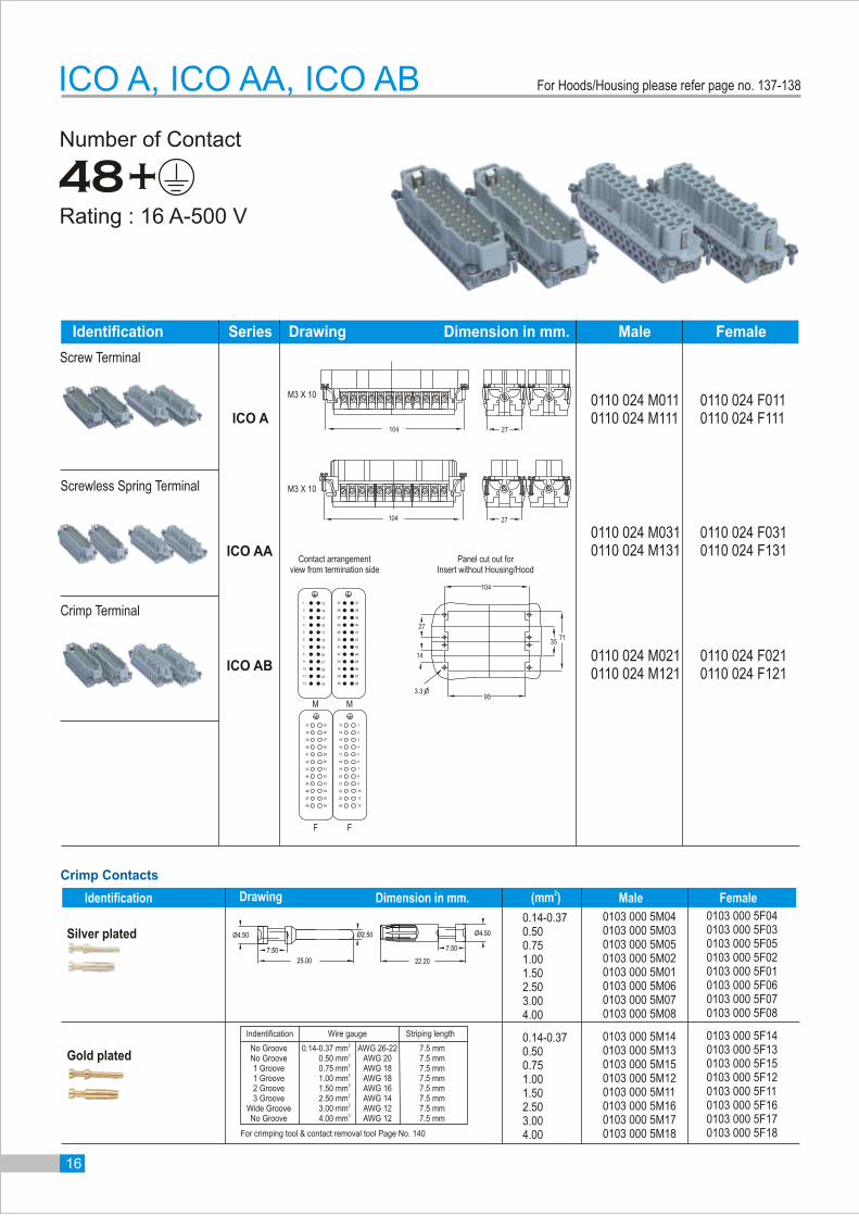
48+Rating : 16 A-500 V
Contact arrangementview from termination side
Panel cut out forInsert without Housing/Hood
35
27
3.3 O
104
37
38
40
41
42
39
43
45
44
46
48
473511 23
12 3624
33219
3410 22
8 3220
284 16
7 3119
6 3018
5 2917
273 15
2 2614
1 2513
11233547
48 36 24 12
9213345
34 2246 10
44 2032 8
4162840
43 31 19
42 1830
7
6
41 29 17 5
39 27 15 3
38 1426
37 1325
2
1
71
95
14
M M
F F
0110 024 M0110110 024 M111
0110 024 F0110110 024 F111
0110 024 F0310110 024 F131
0110 024 F0210110 024 F121
0110 024 M0310110 024 M131
0110 024 M0210110 024 M121
Screwless Spring Terminal
Crimp Terminal
ICO A
ICO AA
ICO AB
Identification Series Drawing Dimension in mm. Male Female
ICO A, ICO AA, ICO AB
Crimp Contacts
0103 000 5M040103 000 5M030103 000 5M050103 000 5M020103 000 5M010103 000 5M060103 000 5M070103 000 5M08
Silver plated
Gold plated
0.14-0.370.500.751.001.502.503.004.00
0103 000 5F040103 000 5F030103 000 5F050103 000 5F020103 000 5F010103 000 5F060103 000 5F070103 000 5F08
0103 000 5M140103 000 5M130103 000 5M150103 000 5M120103 000 5M110103 000 5M160103 000 5M170103 000 5M18
0.14-0.370.500.751.001.502.503.004.00
0103 000 5F140103 000 5F130103 000 5F150103 000 5F120103 000 5F110103 000 5F160103 000 5F170103 000 5F18
Identification Drawing Dimension in mm.2(mm ) Male Female
Screw Terminal
104
M3 X 10
27
27104
M3 X 10
16
For Hoods/Housing please refer page no. 137-138
22.20
7.50
Ø4.50
25.00
7.50
Ø4.50 Ø2.50
Wire gauge Striping length2
0.14-0.37 mm2
0.50 mm2
0.75 mm2
1.00 mm2
1.50 mm2
2.50 mm2
3.00 mm2
4.00 mm
7.5 mm7.5 mm7.5 mm7.5 mm7.5 mm7.5 mm7.5 mm7.5 mm
AWG 26-22AWG 20AWG 18AWG 18AWG 16AWG 14AWG 12AWG 12
Indentification
No GrooveNo Groove1 Groove1 Groove2 Groove3 Groove
Wide GrooveNo Groove
For crimping tool & contact removal tool Page No. 140
indoelectricals.com
17
ICO ABS
ICO ABS
Ambient temperature [ ]oC
Op
era
tin
g c
urr
en
t [A
]
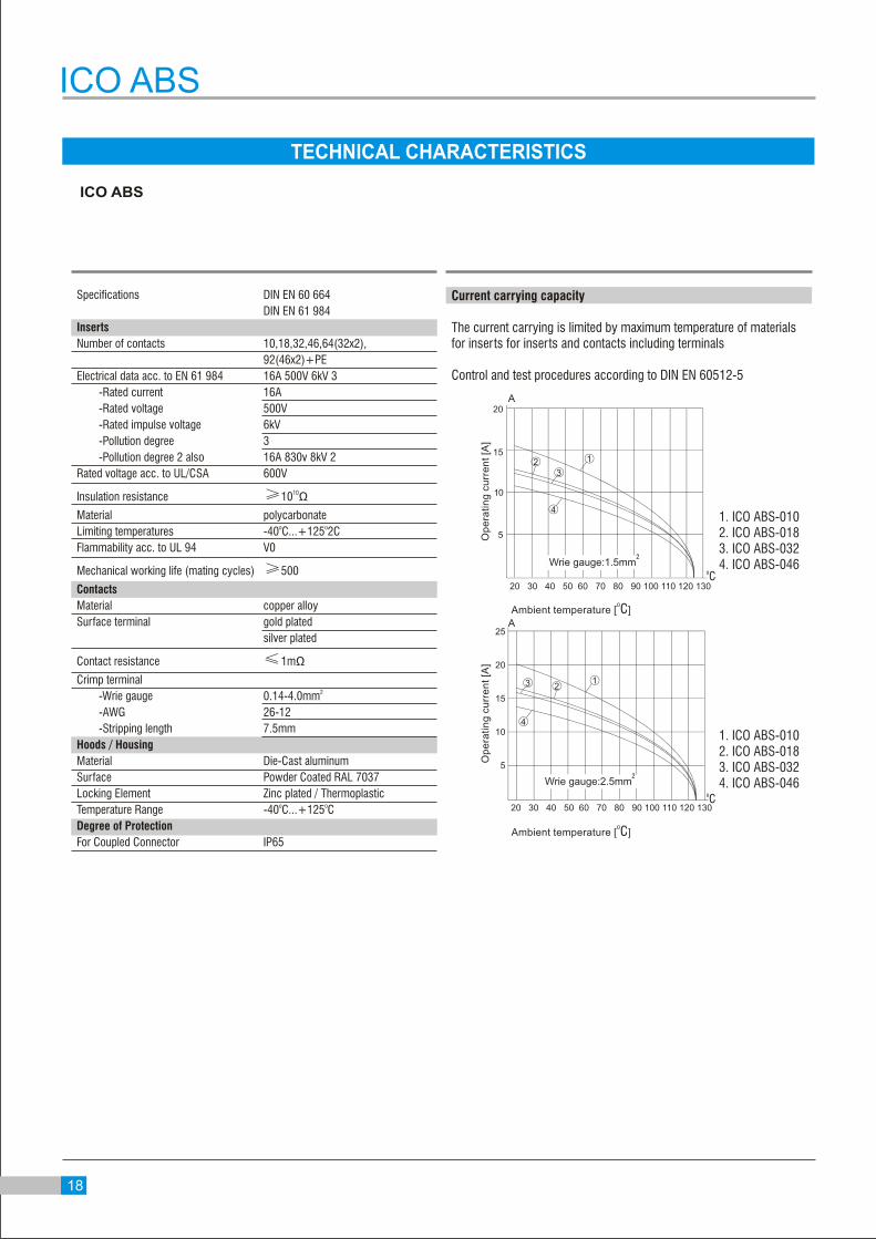
Wrie gauge:2.5mm2
oC
1. ICO ABS-0102. ICO ABS-0183. ICO ABS-0324. ICO ABS-046
A
Ambient temperature [ ]oC
Op
era
tin
g c
urr
en
t [A
]
Wrie gauge:1.5mm2
1. ICO ABS-0102. ICO ABS-0183. ICO ABS-0324. ICO ABS-046
oC
A
Current carrying capacity
The current carrying is limited by maximum temperature of materials for inserts for inserts and contacts including terminals
Control and test procedures according to DIN EN 60512-5
Specifications DIN EN 60 664
DIN EN 61 984
Inserts
Number of contacts 10,18,32,46,64(32x2),
92(46x2)+PE
Electrical data acc. to EN 61 984 16A 500V 6kV 3
-Rated current 16A
-Rated voltage 500V
-Rated impulse voltage 6kV
-Pollution degree 3
-Pollution degree 2 also 16A 830v 8kV 2
Rated voltage acc. to UL/CSA 600V
10Insulation resistance ≥10 Ω
Material polycarbonateo oLimiting temperatures -40 C...+125 2C
Flammability acc. to UL 94 V0
Mechanical working life (mating cycles) ≥500
Contacts
Material copper alloy
Surface terminal gold plated
silver plated
Contact resistance ≤1mΩ
Crimp terminal2 -Wrie gauge 0.14-4.0mm
-AWG 26-12
-Stripping length 7.5mm
Hoods / Housing
Material Die-Cast aluminum
Surface Powder Coated RAL 7037
Locking Element Zinc plated / Thermoplastico oTemperature Range -40 C...+125 C
Degree of Protection
For Coupled Connector IP65
TECHNICAL CHARACTERISTICS
18
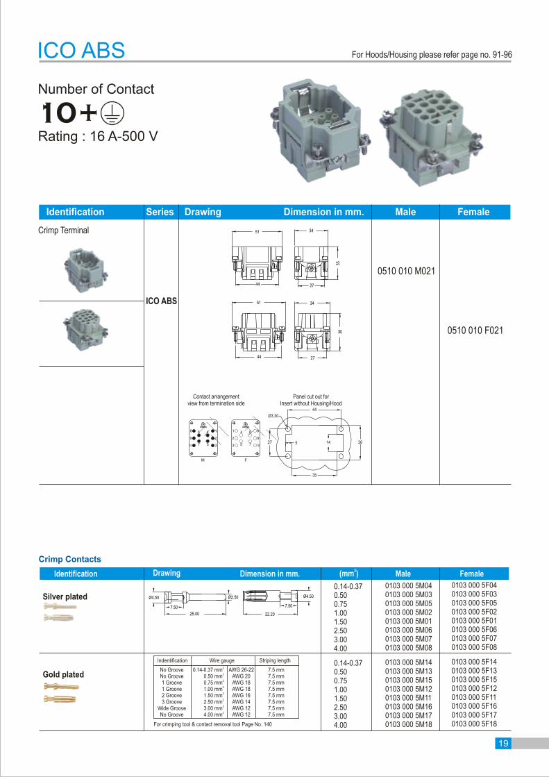
Number of Contact
10+
Identification Series Drawing Dimension in mm. Male Female
0510 010 F021
0510 010 M021
Rating : 16 A-500 V
Crimp Terminal
ICO ABS
34
36
2744
51
34
33
2744
51
ICO ABS
1
2
3
6 4
7 5
8
9
10
1
2
3
64
75
8
9
10
M F
44
27
35
36145
Ø3.30
Contact arrangementview from termination side
Panel cut out forInsert without Housing/Hood
Crimp Contacts
0103 000 5M040103 000 5M030103 000 5M050103 000 5M020103 000 5M010103 000 5M060103 000 5M070103 000 5M08
Silver plated
Gold plated
0.14-0.370.500.751.001.502.503.004.00
0103 000 5F040103 000 5F030103 000 5F050103 000 5F020103 000 5F010103 000 5F060103 000 5F070103 000 5F08
0103 000 5M140103 000 5M130103 000 5M150103 000 5M120103 000 5M110103 000 5M160103 000 5M170103 000 5M18
0.14-0.370.500.751.001.502.503.004.00
0103 000 5F140103 000 5F130103 000 5F150103 000 5F120103 000 5F110103 000 5F160103 000 5F170103 000 5F18
Identification Drawing Dimension in mm.2(mm ) Male Female
For Hoods/Housing please refer page no. 91-96
22.20
7.50
Ø4.50
25.00
7.50
Ø4.50 Ø2.50
Wire gauge Striping length2
0.14-0.37 mm2
0.50 mm2
0.75 mm2
1.00 mm2
1.50 mm2
2.50 mm2
3.00 mm2
4.00 mm
7.5 mm7.5 mm7.5 mm7.5 mm7.5 mm7.5 mm7.5 mm7.5 mm
AWG 26-22AWG 20AWG 18AWG 18AWG 16AWG 14AWG 12AWG 12
Indentification
No GrooveNo Groove1 Groove1 Groove2 Groove3 Groove
Wide GrooveNo Groove
19
For crimping tool & contact removal tool Page No. 140

Number of Contact
18+Rating : 16 A-500 V
Crimp Terminal
Identification Series Drawing Dimension in mm. Male Female
ICO ABS
0510 018 F021
0510 018 M021
34
36
2757
64
34
33
2757
64
ICO ABS
14 610
913
2
3
4
1
5
15
16
17
18
146 10
9 13
2
3
4
1
5
15
16
17
18
M F
27 36145
Ø3.30
57
48
Panel cut out forInsert without Housing/Hood
Contact arrangementview from termination side
Crimp Contacts
0103 000 5M040103 000 5M030103 000 5M050103 000 5M020103 000 5M010103 000 5M060103 000 5M070103 000 5M08
Silver plated
Gold plated
0.14-0.370.500.751.001.502.503.004.00
0103 000 5F040103 000 5F030103 000 5F050103 000 5F020103 000 5F010103 000 5F060103 000 5F070103 000 5F08
0103 000 5M140103 000 5M130103 000 5M150103 000 5M120103 000 5M110103 000 5M160103 000 5M170103 000 5M18
0.14-0.370.500.751.001.502.503.004.00
0103 000 5F140103 000 5F130103 000 5F150103 000 5F120103 000 5F110103 000 5F160103 000 5F170103 000 5F18
Identification Drawing Dimension in mm.2(mm ) Male Female
For Hoods/Housing please refer page no. 101-110
22.20
7.50
Ø4.50
25.00
7.50
Ø4.50 Ø2.50
Wire gauge Striping length2
0.14-0.37 mm2
0.50 mm2
0.75 mm2
1.00 mm2
1.50 mm2
2.50 mm2
3.00 mm2
4.00 mm
7.5 mm7.5 mm7.5 mm7.5 mm7.5 mm7.5 mm7.5 mm7.5 mm
AWG 26-22AWG 20AWG 18AWG 18AWG 16AWG 14AWG 12AWG 12
Indentification
No GrooveNo Groove1 Groove1 Groove2 Groove3 Groove
Wide GrooveNo Groove
20
For crimping tool & contact removal tool Page No. 140

Number of Contact
32+
0510 032 F021
0510 032 M021
Rating : 16 A-500 V
Crimp Terminal
Identification Series Drawing Dimension in mm. Male Female
ICO ABS
34
36
2777.5
84
34
33
2777.5
84
ICO ABS
1
2
3
4
5
6
7
8
9
24
25
26
27
28
29
30
31
32
17 10
23 16
1
2
3
4
5
6
7
8
9
24
25
26
27
28
29
30
31
32
1710
2316
27 36145
Ø3.30
77.50
68.50
M F
Contact arrangementview from termination side
Panel cut out forInsert without Housing/Hood
Crimp Contacts
0103 000 5M040103 000 5M030103 000 5M050103 000 5M020103 000 5M010103 000 5M060103 000 5M070103 000 5M08
Silver plated
Gold plated
0.14-0.370.500.751.001.502.503.004.00
0103 000 5F040103 000 5F030103 000 5F050103 000 5F020103 000 5F010103 000 5F060103 000 5F070103 000 5F08
0103 000 5M140103 000 5M130103 000 5M150103 000 5M120103 000 5M110103 000 5M160103 000 5M170103 000 5M18
0.14-0.370.500.751.001.502.503.004.00
0103 000 5F140103 000 5F130103 000 5F150103 000 5F120103 000 5F110103 000 5F160103 000 5F170103 000 5F18
Identification Drawing Dimension in mm.2(mm ) Male Female
For Hoods/Housing please refer page no. 111-130
22.20
7.50
Ø4.50
25.00
7.50
Ø4.50 Ø2.50
Wire gauge Striping length2
0.14-0.37 mm2
0.50 mm2
0.75 mm2
1.00 mm2
1.50 mm2
2.50 mm2
3.00 mm2
4.00 mm
7.5 mm7.5 mm7.5 mm7.5 mm7.5 mm7.5 mm7.5 mm7.5 mm
AWG 26-22AWG 20AWG 18AWG 18AWG 16AWG 14AWG 12AWG 12
Indentification
No GrooveNo Groove1 Groove1 Groove2 Groove3 Groove
Wide GrooveNo Groove
21
For crimping tool & contact removal tool Page No. 140
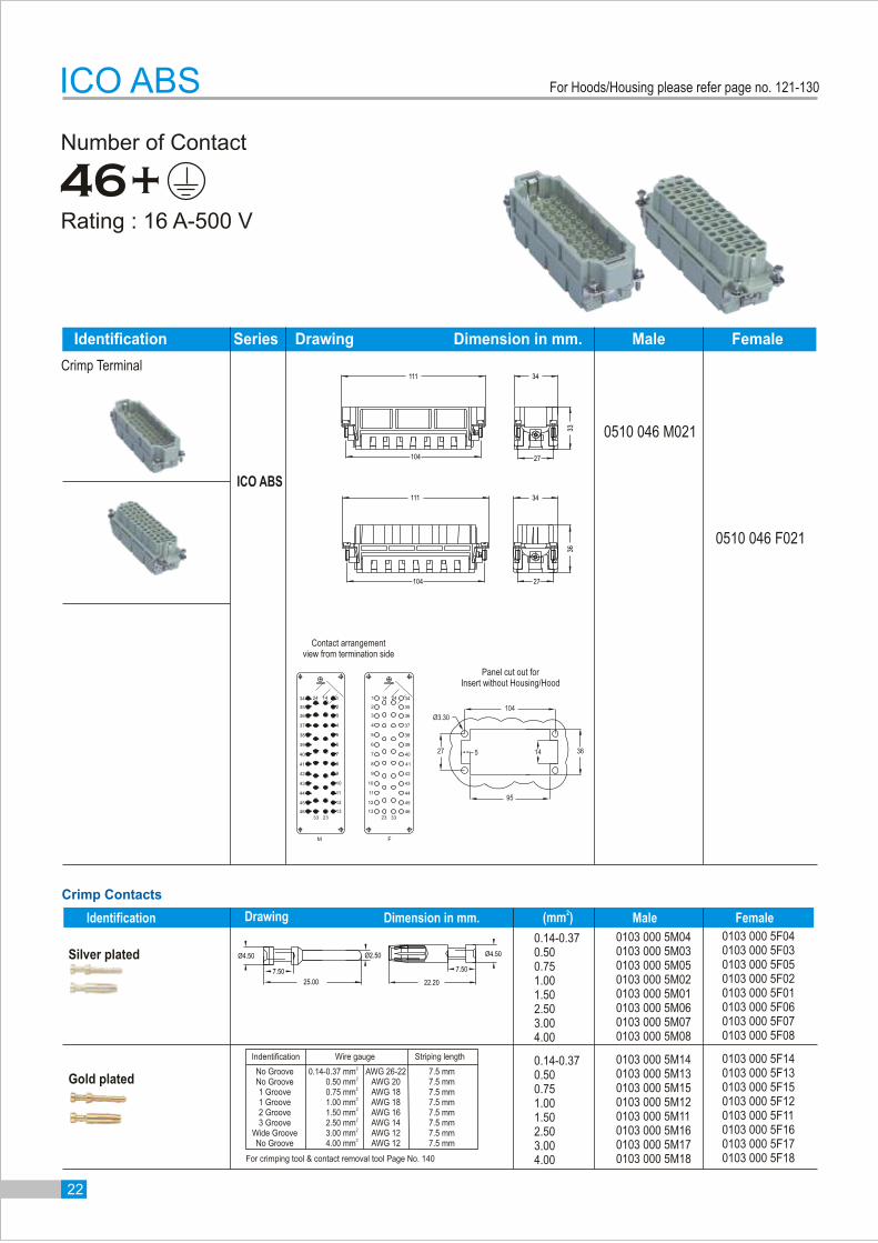
Number of Contact
46+
0510 046 F021
Rating : 16 A-500 V
Crimp Terminal
Identification Series Drawing Dimension in mm. Male Female
ICO ABS
0510 046 M021
111 34
36
27104
111 34
33
27104
ICO ABS
2
3
4
5
6
7
8
9
10
35
36
37
38
39
40
41
42
43
M
1144
1245
1346
134 24 14
33 23
2
3
4
5
6
7
8
9
10
35
36
37
38
39
40
41
42
43
F
11 44
12 45
13 46
1 342414
3323
Panel cut out forInsert without Housing/Hood
Contact arrangementview from termination side
Crimp Contacts
0103 000 5M040103 000 5M030103 000 5M050103 000 5M020103 000 5M010103 000 5M060103 000 5M070103 000 5M08
Silver plated
Gold plated
0.14-0.370.500.751.001.502.503.004.00
0103 000 5F040103 000 5F030103 000 5F050103 000 5F020103 000 5F010103 000 5F060103 000 5F070103 000 5F08
0103 000 5M140103 000 5M130103 000 5M150103 000 5M120103 000 5M110103 000 5M160103 000 5M170103 000 5M18
0.14-0.370.500.751.001.502.503.004.00
0103 000 5F140103 000 5F130103 000 5F150103 000 5F120103 000 5F110103 000 5F160103 000 5F170103 000 5F18
Identification Drawing Dimension in mm.2(mm ) Male Female
27 36145
Ø3.30
104
95
For Hoods/Housing please refer page no. 121-130
22.20
7.50
Ø4.50
25.00
7.50
Ø4.50 Ø2.50
Wire gauge Striping length2
0.14-0.37 mm2
0.50 mm2
0.75 mm2
1.00 mm2
1.50 mm2
2.50 mm2
3.00 mm2
4.00 mm
7.5 mm7.5 mm7.5 mm7.5 mm7.5 mm7.5 mm7.5 mm7.5 mm
AWG 26-22AWG 20AWG 18AWG 18AWG 16AWG 14AWG 12AWG 12
Indentification
No GrooveNo Groove1 Groove1 Groove2 Groove3 Groove
Wide GrooveNo Groove
22
For crimping tool & contact removal tool Page No. 140

Crimp Terminal
Number of Contact
64 (32x2) +Rating : 16 A-500 V
ICO ABS
Identification Series Drawing Dimension in mm. Male Female
0510 032 M0210510 032 M121
0510 032 F0210510 032 F121
ICO ABS
56
57
58
59
60
61
62
63
64
4942
5548
1
2
3
4
5
6
7
8
9
24
25
26
27
28
29
30
31
32
1710
2316
33
34
35
36
37
38
39
40
41
56
57
58
59
60
61
62
63
64
49 42
55 48
1
2
3
4
5
6
7
8
9
24
25
26
27
28
29
30
31
32
17 10
23 16
33
34
35
36
37
38
39
40
41
Panel cut out forInsert without Housing/Hood
Contact arrangementview from termination side
Crimp Contacts
0103 000 5M040103 000 5M030103 000 5M050103 000 5M020103 000 5M010103 000 5M060103 000 5M070103 000 5M08
Silver plated
Gold plated
0.14-0.370.500.751.001.502.503.004.00
0103 000 5F040103 000 5F030103 000 5F050103 000 5F020103 000 5F010103 000 5F060103 000 5F070103 000 5F08
0103 000 5M140103 000 5M130103 000 5M150103 000 5M120103 000 5M110103 000 5M160103 000 5M170103 000 5M18
0.14-0.370.500.751.001.502.503.004.00
0103 000 5F140103 000 5F130103 000 5F150103 000 5F120103 000 5F110103 000 5F160103 000 5F170103 000 5F18
Identification Drawing Dimension in mm.2(mm ) Male Female
77.50
68.50
71.00
27.00
35
Ø3.30
M F
111 34
33
27104
111 34
36
27104
For Hoods/Housing please refer page no. 134-136
22.20
7.50
Ø4.50
25.00
7.50
Ø4.50 Ø2.50
Wire gauge Striping length2
0.14-0.37 mm2
0.50 mm2
0.75 mm2
1.00 mm2
1.50 mm2
2.50 mm2
3.00 mm2
4.00 mm
7.5 mm7.5 mm7.5 mm7.5 mm7.5 mm7.5 mm7.5 mm7.5 mm
AWG 26-22AWG 20AWG 18AWG 18AWG 16AWG 14AWG 12AWG 12
Indentification
No GrooveNo Groove1 Groove1 Groove2 Groove3 Groove
Wide GrooveNo Groove
23
For crimping tool & contact removal tool Page No. 140
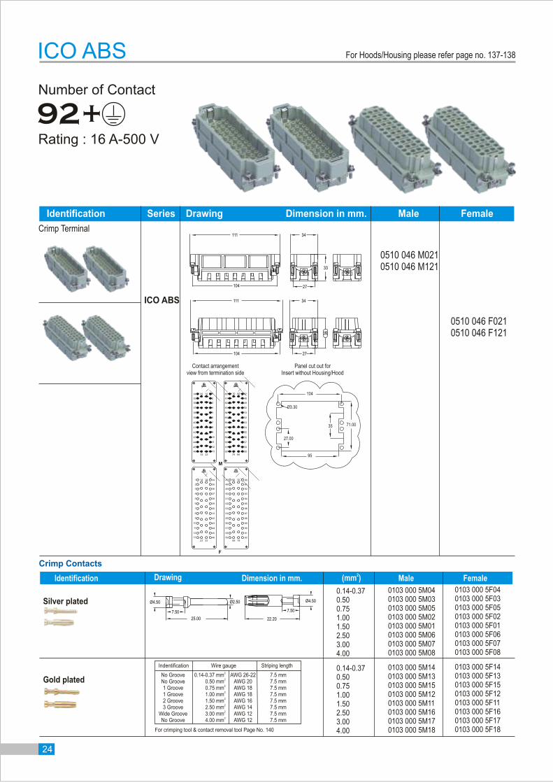
Number of Contact
92+Rating : 16 A-500 V
0510 046 M0210510 046 M121
0510 046 F0210510 046 F121
ICO ABS
Identification Series Drawing Dimension in mm. Male Female
Crimp Terminal
ICO ABS
2
3
4
5
6
7
8
9
10
35
36
37
38
39
40
41
42
43
11 44
12 45
13 46
1 342414
3323
48
49
50
51
52
53
54
55
56
57
58
59
47 60 70
69 79
81
82
83
84
85
86
87
88
89
90
91
92
80
2
3
4
5
6
7
8
9
10
35
36
37
38
39
40
41
42
43
1144
1245
1346
134 24 14
33 23
48
49
50
51
52
53
54
55
56
57
58
59
476070
6979
81
82
83
84
85
86
87
88
89
90
91
92
80
Contact arrangementview from termination side
Panel cut out forInsert without Housing/Hood
Crimp Contacts
0103 000 5M040103 000 5M030103 000 5M050103 000 5M020103 000 5M010103 000 5M060103 000 5M070103 000 5M08
Silver plated
Gold plated
0.14-0.370.500.751.001.502.503.004.00
0103 000 5F040103 000 5F030103 000 5F050103 000 5F020103 000 5F010103 000 5F060103 000 5F070103 000 5F08
0103 000 5M140103 000 5M130103 000 5M150103 000 5M120103 000 5M110103 000 5M160103 000 5M170103 000 5M18
0.14-0.370.500.751.001.502.503.004.00
0103 000 5F140103 000 5F130103 000 5F150103 000 5F120103 000 5F110103 000 5F160103 000 5F170103 000 5F18
Identification Drawing Dimension in mm.2(mm ) Male Female
F
M
111 34
33
27104
111 34
36
27104
71.00
27.00
35
Ø3.30
104
95
For Hoods/Housing please refer page no. 137-138
22.20
7.50
Ø4.50
25.00
7.50
Ø4.50 Ø2.50
Wire gauge Striping length2
0.14-0.37 mm2
0.50 mm2
0.75 mm2
1.00 mm2
1.50 mm2
2.50 mm2
3.00 mm2
4.00 mm
7.5 mm7.5 mm7.5 mm7.5 mm7.5 mm7.5 mm7.5 mm7.5 mm
AWG 26-22AWG 20AWG 18AWG 18AWG 16AWG 14AWG 12AWG 12
Indentification
No GrooveNo Groove1 Groove1 Groove2 Groove3 Groove
Wide GrooveNo Groove
24
For crimping tool & contact removal tool Page No. 140
indoelectricals.com
25
ICO ABE
ICO ABE
Ambient temperature [ ]oC
Op
era
tin
g c
urr
en
t [A
]
1. ICO ABE-0402. ICO ABE-064
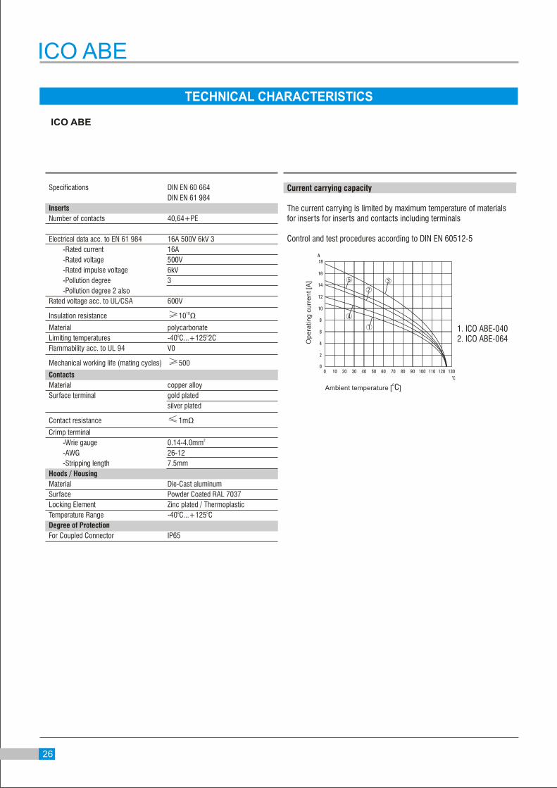
Current carrying capacity
The current carrying is limited by maximum temperature of materials for inserts for inserts and contacts including terminals
Control and test procedures according to DIN EN 60512-5
Specifications DIN EN 60 664
DIN EN 61 984
Inserts
Number of contacts 40,64+PE
Electrical data acc. to EN 61 984 16A 500V 6kV 3
-Rated current 16A
-Rated voltage 500V
-Rated impulse voltage 6kV
-Pollution degree 3
-Pollution degree 2 also
Rated voltage acc. to UL/CSA 600V
10Insulation resistance ≥10 Ω
Material polycarbonateo oLimiting temperatures -40 C...+125 2C
Flammability acc. to UL 94 V0
Mechanical working life (mating cycles) ≥500
Contacts
Material copper alloy
Surface terminal gold plated
silver plated
Contact resistance ≤1mΩ
Crimp terminal2 -Wrie gauge 0.14-4.0mm
-AWG 26-12
-Stripping length 7.5mm
Hoods / Housing
Material Die-Cast aluminum
Surface Powder Coated RAL 7037
Locking Element Zinc plated / Thermoplastico oTemperature Range -40 C...+125 C
Degree of Protection
For Coupled Connector IP65
TECHNICAL CHARACTERISTICS
5
2
4
3
1
18
0
2
4
6
8
10
12
14
16
0 10 20 30 40 50 60 70 80 90 100 110 120 130oC
A
26
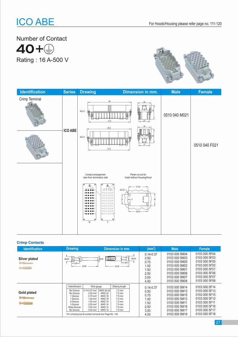
Number of Contact
40+
0510 040 F021
0510 040 M021
Rating : 16 A-500 V
Crimp Terminal
Identification Series Drawing Dimension in mm. Male Female
ICO ABE
ICO ABE
2
3
4
5
6
7
8
9
10
M
1
2
3
4
5
6
7
8
9
10
1D C B A
2
3
4
5
6
7
8
9
10
F
1
2
3
4
5
6
7
8
9
10
1DCBA
27 36145
Ø3.30
77.50
68.50
Contact arrangementview from termination side
Panel cut out forInsert without Housing/Hood
34
27
27
3336
34
77.5
84.5
M3x10
M3x10
77.5
84
Crimp Contacts
0103 000 5M040103 000 5M030103 000 5M050103 000 5M020103 000 5M010103 000 5M060103 000 5M070103 000 5M08
Silver plated
Gold plated
0.14-0.370.500.751.001.502.503.004.00
0103 000 5F040103 000 5F030103 000 5F050103 000 5F020103 000 5F010103 000 5F060103 000 5F070103 000 5F08
0103 000 5M140103 000 5M130103 000 5M150103 000 5M120103 000 5M110103 000 5M160103 000 5M170103 000 5M18
0.14-0.370.500.751.001.502.503.004.00
0103 000 5F140103 000 5F130103 000 5F150103 000 5F120103 000 5F110103 000 5F160103 000 5F170103 000 5F18
Identification Drawing Dimension in mm.2(mm ) Male Female
For Hoods/Housing please refer page no. 111-120
22.20
7.50
Ø4.50
25.00
7.50
Ø4.50 Ø2.50
27
Wire gauge Striping length2
0.14-0.37 mm2
0.50 mm2
0.75 mm2
1.00 mm2
1.50 mm2
2.50 mm2
3.00 mm2
4.00 mm
7.5 mm7.5 mm7.5 mm7.5 mm7.5 mm7.5 mm7.5 mm7.5 mm
AWG 26-22AWG 20AWG 18AWG 18AWG 16AWG 14AWG 12AWG 12
Indentification
No GrooveNo Groove1 Groove1 Groove2 Groove3 Groove
Wide GrooveNo Groove
For crimping tool & contact removal tool Page No. 140

Number of Contact
64+
0510 064 F021
Rating : 16 A-500 V
Crimp Terminal
Identification Series Drawing Dimension in mm. Male Female
ICO ABE
0510 064 M021
111 34
3627104
111 34
33
27104
ICO ABE
Panel cut out forInsert without Housing/Hood
Contact arrangementview from termination side
2
3
4
5
6
7
8
9
10
M
1
2
3
4
5
6
7
8
9
10
1D C B A
2
3
4
5
6
7
8
9
10
F
1
2
3
4
5
6
7
8
9
10
1DCBA
1111
1212
1313
1414
1515
1616
11 11
12 12
13 13
14 14
15 15
16 16
Crimp Contacts
0103 000 5M040103 000 5M030103 000 5M050103 000 5M020103 000 5M010103 000 5M060103 000 5M070103 000 5M08
Silver plated
Gold plated
0.14-0.370.500.751.001.502.503.004.00
0103 000 5F040103 000 5F030103 000 5F050103 000 5F020103 000 5F010103 000 5F060103 000 5F070103 000 5F08
0103 000 5M140103 000 5M130103 000 5M150103 000 5M120103 000 5M110103 000 5M160103 000 5M170103 000 5M18
0.14-0.370.500.751.001.502.503.004.00
0103 000 5F140103 000 5F130103 000 5F150103 000 5F120103 000 5F110103 000 5F160103 000 5F170103 000 5F18
Identification Drawing Dimension in mm.2(mm ) Male Female
27 145
Ø3.30
95
104
36
For Hoods/Housing please refer page no. 121-130
22.20
7.50
Ø4.50
25.00
7.50
Ø4.50 Ø2.50
28
Wire gauge Striping length2
0.14-0.37 mm2
0.50 mm2
0.75 mm2
1.00 mm2
1.50 mm2
2.50 mm2
3.00 mm2
4.00 mm
7.5 mm7.5 mm7.5 mm7.5 mm7.5 mm7.5 mm7.5 mm7.5 mm
AWG 26-22AWG 20AWG 18AWG 18AWG 16AWG 14AWG 12AWG 12
Indentification
No GrooveNo Groove1 Groove1 Groove2 Groove3 Groove
Wide GrooveNo Groove
For crimping tool & contact removal tool Page No. 140
indoelectricals.com
829
ICO C, ICO CA
TECHNICAL CHARACTERISTICS
ICO C, ICO CA
Ambient temperature [ ]oC
Wo
rkin
g c
urr
en
t [A
]1. 2.5 2mm
2mm2. 1.52mm3. 1.0
Ambient temperature [ ]oC
Wo
rkin
g c
urr
en
t [A
]
1. 2.5 2mm2mm2. 1.52mm3. 1.0
Ambient temperature [ ]oC
Wo
rkin
g c
urr
en
t [A
]
1. 2.5 2mm2mm2. 1.52mm3. 1.0
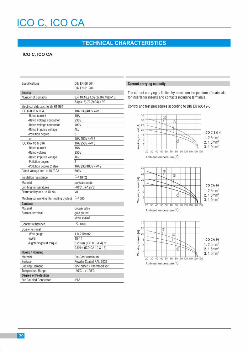
Current carrying capacity
The current carrying is limited by maximum temperature of materials for inserts for inserts and contacts including terminals
Control and test procedures according to DIN EN 60512-5
ICO C 3 & 4
ICO CA 10
ICO CA 16
30

Identification Series Drawing Dimension in mm. Male Female
ICO C
Number of Contact
3+
0120 003 F011
0120 004 M011
Rating : 10 A-250/400 V
& 4+
0120 003 M011
0120 004 F011
21
2727
21
32
21
831
ICO C
ICO C
Contact arrangementview from termination side
1
23
4
M
1
23
4
F
1
23M
1
23F
21
Screw Terminal
Screw Terminal
32
For Hoods/Housing please refer page no. 71-73

ICO CA
Identification Series Drawing Dimension in mm. Male Female
Number of Contact
10+
0140 010 F011
0140 010 M011
Rating : 16 A-250 V
16 32
43.5
3.3 O49.5
10
Panel cut out forInsert without Housing/Hood
2349.5
16
30
56
M3x10
M3x10
56 23
33
49.5 16
Contact arrangementview from termination side
M F
7 22 7
5 10
4 9
3 8
510
3
49
8
1 6 6 1
ICO CA
Screw Terminal
32
For Hoods/Housing please refer page no. 75-76

ICO CA
Identification Series Drawing Dimension in mm. Male Female
Number of Contact
16+Rating : 16 A-250 V
Panel cut out forInsert without Housing/Hood
Contact arrangementview from termination side
M F
816 168
513
6
412
715
14
135
6
124
157
14
9 1
311
210
1 9
113
102
0140 016 F011M3x10
23
30
72.5
1666
23
16
33.5
73
M3x10
0140 016 M011
66
833
ICO CA
Screw Terminal
For Hoods/Housing please refer page no. 77-78
32
60
3.3 O66
16 10

Identification Series Drawing Dimension in mm. Male Female
ICO CA
ICO CA
Screw Terminal
34
For Hoods/Housing please refer page no. 79-80
32
60
3.3 O66
16 10

ICO CA
Identification Series Drawing Dimension in mm. Male Female
Number of Contact
32(16x2)+Rating : 16 A-250 V
Panel cut out forInsert without Housing/Hood
24
60
10
3.30 O
16
66
56
Contact arrangementview from termination side
M M
F F
1321
22
24
23
30
32
31
614
816
15 7
6
8
7
18
17
20
19
25
26
28
29
27
1
19
210
4
5
12
311
2
5
4
3
2113
30
32
31
2214
2416
2315
17 259
26
29
28
27
1810
2012
1911
0140 016 M111
0140 016 M011M3 X 10
16
30
2373
66
0140 016 F111
0140 016 F011M3 X 10
66
72.5
16
23
30
835
ICO CA
Screw Terminal
For Hoods/Housing please refer page no. 81-84

ICO CA
Identification Series Drawing Dimension in mm. Male Female
Number of Contact
48 (16x3)+Rating : 16 A-250 V
Contact arrangementview from termination side
M
F
M
40
37
38
36
39
33
35
34
48
45
44
47
46
41
43
42
M
24
21
22
20
23
17
19
18
32
29
28
31
30
25
27
26
8
5
6
4
7
1
3
2
16
13
12
15
14
9
11
10
F
33
36
37
34
35
40
38
39
41
44
43
45
42
48
46
47
F
9
12
13
10
11
16
14
15
1
4
3
5
2
8
6
7
17
20
21
18
19
24
22
23
25
28
29
26
27
32
30
31
0140 016 F1110140 016 F011
0140 016 F211M3x10
72.5
6623
30
16
0140 016 M1110140 016 M011
0140 016 M211
73
M3x10
66
23
16
33.5
ICO CA
Screw Terminal
36
For Hoods/Housing please refer page no. 85-88

Identification Series Drawing Dimension in mm. Male Female
ICO CA
837
ICO CA
Screw Terminal
64 (16x4)+
For Hoods/Housing please refer page no. 89
73 23
33.5
1666
6623
16
30
72.5

Identification Series Drawing Dimension in mm. Male Female
ICO CA
ICO CA
Screw Terminal
72 (24x3)+
38
For Hoods/Housing please refer page no. 89
23
33.5
16104
30
16
23
104