Qualification of innovative floating substructures for ... · D7.5 Guidance on platform and mooring...
70
Qualification of innovative floating substructures for 10MW wind turbines and water depths greater than 50m Project acronym LIFES50+ Grant agreement 640741 Collaborative project Start date 2015-06-01 Duration 40 months Deliverable 7.5 Guidance on platform and mooring line selection, installation and marine operations Lead Beneficiary USTUTT Due date 2016-07-31 Delivery date 2016-08-03 Dissemination level Public Status Final Classification Unrestricted Keywords floating wind turbines, concept selection, mooring line design, installation and marine operations Company document number Click here to enter text. The research leading to these results has received funding from the European Union Horizon2020 programme under the agreement H2020-LCE-2014-1-640741.
Transcript of Qualification of innovative floating substructures for ... · D7.5 Guidance on platform and mooring...

Qualification of innovative floating substructures for
10MW wind turbines and water depths greater than 50m
Project acronym LIFES50+ Grant agreement 640741
Collaborative project Start date 2015-06-01 Duration 40 months
Deliverable 7.5 Guidance on platform and mooring line selection,
installation and marine operations
Lead Beneficiary USTUTT
Due date 2016-07-31
Delivery date 2016-08-03
Dissemination level Public
Status Final
Classification Unrestricted
Keywords floating wind turbines, concept selection, mooring line design, installation and marine operations
Company document number Click here to enter text.
The research leading to these results has received funding from the
European Union Horizon2020 programme under the agreement
H2020-LCE-2014-1-640741.

D7.5 Guidance on platform and mooring line selection, installation and marine operations
LIFES50+ Deliverable, project 640741 2/70
Disclaimer
The content of the publication herein is the sole responsibility of the publishers and it does not neces-sarily represent the views expressed by the European Commission or its services.
While the information contained in the documents is believed to be accurate, the authors(s) or any other participant in the LIFES50+ consortium make no warranty of any kind with regard to this material including, but not limited to the implied warranties of merchantability and fitness for a particular pur-pose.
Neither the LIFES50+ Consortium nor any of its members, their officers, employees or agents shall be responsible or liable in negligence or otherwise howsoever in respect of any inaccuracy or omission herein.
Without derogating from the generality of the foregoing neither the LIFES50+ Consortium nor any of its members, their officers, employees or agents shall be liable for any direct or indirect or consequential loss or damage caused by or arising from any information advice or inaccuracy or omission herein.
Document information
Version Date Description
2 2017-07-03 Advanced draft
Prepared by Kolja Müller, Denis Matha, Michael Karch,
Simon Tiedemann
Reviewed by Luca Vita, Roberts Proskovics, Gonzalo Gonzales
Approved by Kolja Müller
3 2015-07-24 Final draft for review
Prepared by Kolja Müller, Denis Matha, Michael Karch,
Simon Tiedemann, Roberts Proskovics
Reviewed by Roberts Proskovics, Iñigo Mendikoa Alonso
Approved by Kolja Müller
Final 2017-08-03 Final version for QA before submission
Prepared by Kolja Müller, Denis Matha, Michael Karch,
Simon Tiedemann, Roberts Proskovics
Reviewed by Kolja Müller, Denis Matha
Approved by Jan Arthur Norbeck
In order to enter a new version row, copy the above and paste into left most cell.
Authors Organization
Müller, K. University of Stuttgart
Matha, D. Ramboll
Tiedemann, S. Ramboll
Proskovics, R. ORE Catapult
Lemmer, F. University of Stuttgart

D7.5 Guidance on platform and mooring line selection, installation and marine operations
LIFES50+ Deliverable, project 640741 3/70
Contributors Organization
Schlipf, D. University of Stuttgart
Lemmer, F. University of Stuttgart
Faerron-Guzman, R. University of Stuttgart
Rösler, J. University of Stuttgart
Pan, Q. University of Stuttgart
Vita, L. DNV GL
Karch, M. Ramboll
Tiedemann, S. Ramboll
Amate, J. Iberdrola
González, G. Iberdrola
Sánchez, G. Iberdrola
Landbø, T. Olav Olsen
Andersen, H. Olav Olsen
Jones, W. Ideol
Ugwu, J. ORE Catapult
Perez, G. Tecnalia
Mendikoa, I. Tecnalia
Delhaye, V. SINTEF Ocean
Robertson, A. NREL
Jonkman, J. NREL
Sirnivas, S. NREL
Damiani, R. NREL
Musial, W. NREL
Wendt, F. NREL

D7.5 Guidance on platform and mooring line selection, installation and marine operations
LIFES50+ Deliverable, project 640741 4/70
Definitions & Abbreviations
AST Administrative Support Team
AHV Anchor handling tug
ALS Accidental limit state
AUV Autonomous underwater vehicle
DFF Design fatigue factor
DLC Design load case
DP Dynamic positioning
FLS Fatigue limit state
FOWT Floating offshore wind turbine
LCA Life Cycle Assessment
LCOE Levelized cost of energy
MRL manufacturing readiness level
MSV Multi service vessel
MW Megawatt
O&M Operation and maintenance
OEM Original equipment manufacturer
PC Project Coordinator
PM Project Manager
QTF Quadratic transfer function
RAO Response amplitude operator
RNA Rotor Nacelle Assembly
ROV Remotely operated vehicle
SPMT Self-Propelled Modular Transporter
TLP Tension leg platform
TLS Tension leg system
TRL Technology readiness level
ULS Ultimate limit state
VIV Vortex induced vibrations
WP Work package
WPL Work Package Leader
WTG Wind turbine generator
AST Administrative Support Team
AHV Anchor handling tug

D7.5 Guidance on platform and mooring line selection, installation and marine operations
LIFES50+ Deliverable, project 640741 5/70
Executive Summary
The increasing relevance of industrialization capabilities of the available concepts for floating wind
turbine platforms goes in line with the progress in the development of technology and manufacturing
readiness. A key part of LIFES50+ effort is the development of industrialized processes which will
allow for significant cost reduction through serial production, standardization, and optimized handling
procedures along the lifecycle of the system. Complementarily, methods to determine the costs and
risks of floating offshore wind turbine systems were developed in order to evaluate and rate the results.
This deliverable provides a comprehensive and generalized overview of the achievements of
LIFES50+ with respect to industrialization of the FOWT technology.
In particular, this deliverable focusses on the following items:
(1) Platform selection
A list of parameters, which are needed to set up a decision making process, is defined and embedded
into an optimization procedure by classifying the parameters into constraints, design parameters and
performance indicators. This way, a transparent and systematic view on the selection and optimization
procedure is given for finding the optimal concept for a given site.
(2) Station keeping
The mooring line design process is described, providing considerations during the design and listing
relevant standards and load cases for catenary and taut mooring lines. Upscaling and risk considera-
tions are also addressed.
(3) Installation and marine operations
Topics of marine operations and installation processes are covered, which constitute a large factor for
cost reduction for floating offshore wind turbine projects. Common procedures are presented and dif-
ferences between different concepts, constraints, challenges and risks are highlighted. A special focus
is put on equipment to be used as well as on assembly methodologies.
The upcoming deliverable 7.10 on O&M, logistics, manufacturing and decommissioning can be re-
garded as a supplement to this document on topics of industrialization.

D7.5 Guidance on platform and mooring line selection, installation and marine operations
LIFES50+ Deliverable, project 640741 6/70
Contents
1 Introduction ..................................................................................................................................... 7
2 Platform selection ............................................................................................................................ 8
2.1 Introduction ............................................................................................................................. 8
2.2 Optimization problem description ........................................................................................... 9
2.3 Previous research ................................................................................................................... 11
2.4 Optimization problem for concept selection ......................................................................... 15
2.5 10 MW specific issues ........................................................................................................... 23
3 Design of the station keeping system ............................................................................................ 29
3.1 Introduction ........................................................................................................................... 29
3.2 General Design Procedure ..................................................................................................... 29
3.3 Design methodology for a spread mooring system ............................................................... 30
3.4 Design methodology for a tension leg system ....................................................................... 40
3.5 Optimization of station keeping system ................................................................................ 42
3.6 Upscaling considerations and challenges for large wind turbines ......................................... 48
3.7 Risk consideration in design of station keeping system ........................................................ 48
3.8 LIFES50+ mooring design in WP5 ....................................................................................... 49
4 Installation and marine operations ................................................................................................. 53
4.1 Introduction ........................................................................................................................... 53
4.2 Common installation procedures for floating structures ....................................................... 54
4.3 Equipment ............................................................................................................................. 62
4.4 Assembly ............................................................................................................................... 64
4.5 At port.................................................................................................................................... 64
4.6 Risk consideration for installation and marine operations .................................................... 64
5 Bibliography .................................................................................................................................. 67
D7.5 Guidance on platform and mooring line selection, installation and marine operations
LIFES50+ Deliverable, project 640741 7/70
1 Introduction
With the increasing technology and manufacturing readiness level (TRL and MRL) of available sub-
structures for floating offshore wind turbines (FOWT), the industrialization capabilities, which allow
for low-cost mass production, become increasingly important in the design of advanced concepts. The
main items required to achieve a high level of industrialization and to reduce costs have been named as
standardised designs, optimised fabrication lines, easier assembly, transportation, installation, and
decommissioning (James, 2015). With floating wind soon to arrive at a pre-commercial status, consid-
erations of manufacturability, fabrication constraints, serial production, design complexity reduction,
assembly, supply chain, installation, geotechnics, operation and maintenance (O&M) and risk are ad-
dressed as part of distinctive efforts in the LIFES50+ project. These aim at further increasing the TRL
and MRL and developing an industrialized setting for future FOWT substructures.
To this point, substantial experience for industrialization was collected as part of the work performed
in LIFES50+: In the design task in work package (WP) 1, the four different concepts were up-scaled to
carry a 10MW turbine and withstand the loads from three representative sites of different environmen-
tal severity. Part of the work was also the consideration of fabrication, installation and O&M require-
ments. The designs were presented in (Sanchez, et al., 2017) and the relevant experiences for the up-
scaling were collected in (Pérez, et al., 2017). The work provided insight into the different FOWT
design philosophies present in the project and their performance at the different sites. The definition
and application of a risk assessment methodology in WP6 as presented in (Hutton, et al., 2015) ena-
bled the quantification and adequate addressing of critical items that could potentially lead, among
other consequences, to failure of the structures. Based on efforts in WP2, it was made possible to
compare the fundamentally different designs based on the definition of tools to assess the levelized
cost of energy (LCOE), as well as the technical and environmental impact, which were presented in
(Benveniste, et al., 2016). In the continuation of the project, the two selected designs are addressed in
more detail and optimized designs are developed, a part of which is the incorporation of industrializa-
tion considerations. Topics focussing on industrialization are addressed in WP5, where a roadmap to
an industrialized design process was presented in (Matha, et al., 2016) and procedures for numerical
simulations in the mooring line design where investigated towards their application in an industrialized
environment (Matha, et al., 2017).
As part of the work in WP7 and leading to this deliverable the abovementioned project results provid-
ing insight to industrialized design procedures for FOWT substructures were collected, scrutinized and
summarized to provide a comprehensive and generalized overview on the achievements of LIFES50+
aiming at an industrialization of the FOWT community.
In particular, this deliverable focusses on the following items: platform selection, station keeping, and
installation and marine operations as well as related risks and challenges to be expected in upscaling
activities and the installation of large wind farms. The upcoming deliverable 7.10 on O&M, logistics,
manufacturing and decommissioning can be regarded as a supplement to this document on topics of
industrialization.

D7.5 Guidance on platform and mooring line selection, installation and marine operations
LIFES50+ Deliverable, project 640741 8/70
The deliverable is organized as follows:
Chapter 2 describes the selection procedure of substructure concepts for a given site. As this is a no
straightforward task, it was decided to abstract and embed the connected evaluation of the boundary
conditions into an optimization procedure. This provides a transparent view on the decision making
procedure which is performed in the selection and optimization of site specific FOWT substructure
concepts.
Chapter 3 describes the mooring line design process, providing considerations during the design and
listing relevant standards and load cases for spread and tension mooring lines. Upscaling and risk con-
siderations are also addressed.
Chapter 4 covers topics of marine operations and installation processes, which constitute a large factor
for cost reduction for FOWT projects. Common procedures are presented and differences between
different concepts, constraints, challenges and risks are highlighted. A special focus is put on equip-
ment to be used as well as on assembly methodology.
2 Platform selection
2.1 Introduction When searching the optimal site specific design solution of FOWT substructures, the aim is to find the
best compromise between the system costs and the overall system performance. Significant work has
been performed in the past on investigating the advantages and disadvantages of different platform
concepts and on procedures to find optimal platforms for predefined site conditions. These are pre-
sented in section 2.3. The basic, functional requirements of FOWT substructures were summarized by
(Henderson, et al., 2010):
1. Maintain the turbine rotor sufficiently high above the sea
2. Maintain position within the range required for the power cable
3. Counteract the turbine’s thrust, torque and yaw loads
4. Provide a sufficiently stable base for the wind turbine, i.e. to counteract the wave and sea-
current loads
The solutions to these objectives are typically linked to the fundamental static stability characteristic
of a considered platform: barge (water plane area stabilized), spar (ballast stabilized) and tension leg
(mooring line stabilized), which can be combined in the pitch restoring stiffness coefficient:
(1)
The selection of the platform or the stability classification can be seen as the first design step of
FOWT substructure design. Once this is established, the determination of the many different parame-
ters describing the platform is performed as highlighted e.g. in (Müller, et al., 2016), keeping in mind
the abovementioned basic functional requirements. While this may lead to seemingly optimal solu-
tions, satisfying only the functional requirements (which in itself is by no means is a simple task) is a
strong reduction in the scope of the overall FOWT design procedure. It misses the various and com-
plex influences, decisions and constraints that are part of the design and hence can only account for a
fraction of what a designer has to deliver when defining an FOWT substructure concept.

D7.5 Guidance on platform and mooring line selection, installation and marine operations
LIFES50+ Deliverable, project 640741 9/70
The complexity of interactions within the overall FOWT system throughout its lifetime makes it diffi-
cult to determine the one best concept as it is not straight forward to pin down one indicator next to the
LCOE (which only reveals itself once all design parameters are fixed) that could serve as a global
performance measure for any platform. Rather, the concept selection is seen here as an optimization
process for a given site, including different possible designs with competing characteristics that (once
they are expressed in terms of cost) sum up to the LCOE. Even though this may shed some light on the
compromises to be made, a simple definition or solution of the overall problem that applies for any
designer on the market may not be possible, due to the numerical effort required for the suitability
check of any given concept as well as the developer-dependent design constraints (e.g. availability of
production units). Successful FOWT-designers will know their possibilities and limitations regarding
different platforms, station keeping systems, installation methods, design tools, site conditions, etc.
and will draw economically feasible conclusions in the form of compromises from them.
This chapter first introduces an approach for the problem definition for finding optimal design solu-
tions. The approach is subsequently used in order to evaluate previous research on the topic. Building
on the previous research as well as a questionnaire that was sent out to LIFE50+ partners, the problem
description was defined for the platform selection.
2.2 Optimization problem description It is the aim of this work to provide a list of parameters that are needed to set up a decision making
process. These will give a more transparent and systematic view on the procedure which is part of
selecting a concept for a given site. As done for shipbuilding (Papanikolaou, 2011), the decision mak-
ing can be viewed as the solution of an optimization problem which is formulated around three key
parameters:
Constraints
Constraints are the hard limits of the design and result from the environment of the considered design
(e.g. site conditions, serviceability limits of the chosen turbine, water depth…). The design must be
within these constraints, so the constraints define the limits of the design space.
Design parameters
Design parameters represent the different qualitative and quantitative decisions the designer has to
make as part of each design realization (e.g. which platform type, which material to use, wall thick-
ness, etc.). Design parameters can be chosen by a new decision making or optimization process (if
sufficient information is available) or randomly (if sufficient information is not available).
Performance indicators
Performance indicators of a given design evaluate the different characteristics of the system (e.g. ma-
terial weight, installation time, etc.). The different indicators are usually transformed into costs,
weighted and result in the overall objective of the performed optimization (e.g. the LCOE).

D7.5 Guidance on platform and mooring line selection, installation and marine operations
LIFES50+ Deliverable, project 640741 10/70
Figure 1: FOWT platform selection optimization problem
A sketch of the overall optimization procedure for FOWT is described in Figure 1. The description of
the selection and optimization process is aiming at a high level overview and does not entirely go in
line with industry procedures particularly due to the following items:
1. The mooring lines are considered as a design parameter of the platform optimization, which
can be optimized separately, see chapter 3. It should be kept in mind that the mooring system
significantly influences also the platform type (see Eq. (1)), but is seen at a lower importance,
especially when focussing on mooring line characteristics such as material, additional ele-
ments and connectors. In this way, the decision on the platform type includes the definition of
tension constraints for the mooring system.
2. In an industrial setting and as part of a typical tendering process, it is to be expected that the
client contacts a number of (preselected) concept developers for a given site. As the develop-
ers typically focus on one design which is then optimized site specifically, the choice for a cer-
tain substructure geometry (and other parameters such as e.g. material, mooring lines, etc.) can
be seen as preselection prior to the substructure optimization as described in Figure 1. For
simplification and better overview, design parameters are taken as variables in this work, even
though this likely is not the case in the industry, where certain parameters may be fixed for
concept developers.
It is likely that a small number of criteria (such as water depth, draft, footprint and maximum motions)
will drive the overall platform selection procedure for a given site, as some concepts may result in
economically unfeasible designs. If in principle a concept can be used for a given site, the evaluation
of which concept is likely to perform best at this site will be extremely difficult due to the many prop-
erties of a platform. Even if one concept may initially seem unfit for a given site, design specific assets
(e.g. efficient installation procedure) may balance out other disadvantage for one particular design
(e.g. higher manufacturing cost).

D7.5 Guidance on platform and mooring line selection, installation and marine operations
LIFES50+ Deliverable, project 640741 11/70
This complexity of the design when taking into account all life cycle stages of the system leads to the
importance of the definition of performance indicators, which allow for a transparent view on the
overall characteristic for a given system.
2.3 Previous research Using the framework presented in the previous section, previous research focussing on optimization of
designs and comparison between different concepts will now be analysed in order to describe the op-
timization problem.
- (Butterfield, et al., 2005), review
o Performance indicators
A differentiation of the advantages and disadvantages of different platform types,
which are expected to influence the performance and cost of a floating platform, was
provided and is shown in Table 1. These can be regarded as performance indicators
for this work. It is worth mentioning that the impact on turbine stability classification
is regarded as a separate item, to be evaluated independent of the platform perfor-
mance.
- (Tracy, 2007), optimization
o Constraints
Stability during towing and operation, dynamic pitch, line tension, slamming height/
air gap
o Performance indicators
Nacelle acceleration, static plus three sigma tensions, displaced volume
- (Jonkman, et al., 2011), (Robertson, et al., 2011), (Matha, 2010), load comparison
o Performance indicators
Different load cases were evaluated and the sea to land ratio of different dynamic re-
sponses was used as a means of quantifying the impact of the platform on the turbine.
Table 2 summarizes the performance of the different platform types.
- (de Boom, 2011), semi-submersible concept presentation
o Performance indicators
Platform: access, lifting operations next to floating body within short time,
disconnection and tow-away to harbor possible
Mooring lines: restoring force characteristics. Figure 4 shows a mooring system providing a linear restoring behavior.
- (Fylling, et al., 2011), optimization
o Constraints
Turbine: max tower inclination angle, max nacelle acceleration
Platform: max draft, heave/pitch period boundaries
Mooring lines: min/max tension, min fatigue life, max slope angle at anchor
o Design parameters
Platform: cylinder and heave plate dimensions, vertical position of mooring
line fairleads, submerged weight
Mooring lines: line orientation, pretension/distance to anchor, segmentation
o Performance indicators
combined costs of platform, cable and mooring lines
- (Bachynski, et al., 2012), TLP design study

D7.5 Guidance on platform and mooring line selection, installation and marine operations
LIFES50+ Deliverable, project 640741 12/70
o Constraints
Survival under seismic loads, water depth, platform natural period such that the first-
order wave excitation is avoided (e.g. surge and sway > 25s, heave, roll, pitch <3.5s),
maximum mean offset to limit angle at tendon connectors, minimum displacement,
minimum tendon cross sectional area to prevent failure.
o Design parameters
Displaced volume, water plane area/inertia moment, center of buoyancy, center of
gravity, number of mooring lines, mooring line angle, platform shape, mooring line
material, anchor type, column diameter, pontoon radius, permanent ballast weight,
natural periods, stiffness
o Performance indicators
Structural loads on wind turbine and tendons, platform motions, power production,
mooring line pretension, steel mass, displacement, load variation
- (Castro-Santos, et al., 2013), LCOE study
o Performance indicators
It was indicated that most of the costs are to be expected from the manufacturing
(number of wind turbines, power of each wind turbine, mass of platform and wind
turbine, cost of steel, direct labour, direct material and activities) and exploitation
(cost for taxes, assurance exploitation management and O&M) life cycle phases, see
Figure 2. A large number of cost items was established which could be helpful to de-
termine more detailed cost drivers / performance indicators.
- (Myhr, et al., 2014), LCOE study
o Performance indicators
A substantially increased steel price sensitivity of LCOE for steel based structures was
identified (and a consequent LCOE uncertainty of up to ca. 5%), and an influence of
the water depth related to mooring system costs. No remarkable change of sensitivity
between different platform concepts was found for farm size, distance to shore, pro-
ject life span, load factor or discount rate. The results also show the contribution of
different components to the overall substructure costs (see Figure 3).
- (Hall, et al., 2014), (Hall, et al., 2013), optimization
o Constraints
Static pitch angle, dynamic pitch angle, slackline events
o Design parameters
Several platform geometry variables (e.g. diameter and column spacing), mooring line
configurations
o Performance indicators
Nacelle acceleration, support structure cost
- (Adam, et al., 2015), TLP load comparison (wave tank experiments)
o Performance indicators
Max accelerations
- (Strach-Sonsalla, et al., 2016), review
o Constraints
Natural frequency outside of 1P, 3P excitation, survival under extreme conditions and
failure, air gap, sloshing, operational limits in inclination, acceleration and motion
amplitudes, hydrodynamic stability during normal operation
- (Lemmer, et al., 2016), optimization
o Constraints
Draft, hydrostatic pitch stiffness

D7.5 Guidance on platform and mooring line selection, installation and marine operations
LIFES50+ Deliverable, project 640741 13/70
o Design parameters
Platform radius, column spacing, heave plate thickness, ratio of heave plate
radius and column radius
o Performance indicators
Cost (weight), standard deviation of tower top displacement, mass moment of
inertia
Table 1: Design Challenge Tradeoffs for Stability Criteria (Butterfield, et al., 2005)
Table 2: Qualitative assessment of offshore wind turbine floating platform classes (Jonkman, et al., 2011), indicating
relative advantage (‘+’) and disadvantage (‘-‘).

D7.5 Guidance on platform and mooring line selection, installation and marine operations
LIFES50+ Deliverable, project 640741 14/70
Figure 2: Percentage of the costs for different floating platform models. C1: Definition cost, C2: Design cost, C3:
Manufacturing cost, C4: Installation cost, C5: Exploitation cost, C6: Dismantling cost (Castro-Santos, et al., 2013)
Figure 3: CAPEX quantification per MW for different concepts (water depth: 200m) (Myhr, et al., 2014)
Figure 4: GustoMSC mooring connection with advanced restoring characteristics (de Boom, 2011)

D7.5 Guidance on platform and mooring line selection, installation and marine operations
LIFES50+ Deliverable, project 640741 15/70
2.4 Optimization problem for concept selection
Based on the previous research listed above and on a questionnaire filled out by the LIFES50+ partici-
pants the constraints, design parameters and performance indicators describing the search for optimal
floating wind turbine substructures is assessed and provided below. Note that all items provided here
are resulting from the authors’ evaluation of different sources of input and thus may not represent the
opinion of all LIFES50+ consortium members to the last detail. Also, the provided lists may not be
complete and could be subject to change in the future.
2.4.1 Constraints
In general, a site specific platform is considered to be designed in accordance with the applicable
guidelines (applied for the given site conditions). This typically means ensuring that the environmental
loads can be endured by the designed system over the full life time. More restrictions from other life
cycle stages are present, however, these might be more dependent on the individual designer or local
government but also need to be taken into account (e.g. maximum sizes of components from a logis-
tics point of view).
In this section, relevant constraints are presented in Table 3. They are classified according to a related
life cycle category and described in more detail below. An alternative view to categorize the design
constraints may be a division between environmental and logistical parameters, which is not done
here, but could, potentially, better separate the items for different stages in the design.
Additional constraints regarding installation and assembly are also given in section 4.2.5.
Table 3: Constraints in the decision making of FOWT support structure selection
Life cycle
category
Constraint
D Numerical / design effort
D Mooring line footprint
D Site conditions
ML Component dimensions / weights
ML Material
IA Stability during transport
IA System dimensions
IA Weight
IA Minimum weather window
OM Stability, motions & accelerations (SLS)
OM Frequency constraints
OM Load constraints (ULS, FLS, ALS)
DC Decommissioning constraints
D – Design
ML – Manufacturing & Logistics
IA – Installation & Assembly
OM – Operation & Maintenance
DC– Decommissioning
Numerical /design effort: The numerical/design effort required to design a FOWT system within
guideline requirements might be excessively large, if the structure or parts is too complex or too little
information exists on the behavior of the structure. While the design of both substructures and wind
D7.5 Guidance on platform and mooring line selection, installation and marine operations
LIFES50+ Deliverable, project 640741 16/70
turbines is well known in the adjacent industries, the challenge meant here is resulting from the effects
of the coupled systems (aerodynamic, hydrodynamic, controller domains), which need to be taken into
consideration.
Mooring line footprint: The site-specific design may require a maximum footprint per installed unit
to be fulfilled in order to meet designated distance between turbines / area requirements.
Site conditions: Site conditions may prohibit the use of certain platform types. In particular, the water
depth may disqualify concepts with increased draft (e.g. spar) or certain mooring systems (e.g. catena-
ry) and hence the platforms relying on them. The maximum drift allowed from the dynamic cable per-
spective (10-20% of water depth) will impose stiffness constraints on the system that might be impos-
sible to realize. If occurrence of ice loads is likely, this needs to be considered in the design. Geotech-
nical and –physical site conditions may prohibit the use of certain anchoring systems that define a
given concept. The occurrence possibility of extreme events such as typhoons or cyclones can also
constrain the use of certain concepts.
Component dimensions / weights: Dimensions / weights of components and materials have to be
kept within limits in order to stay within the limits of the logistic chain or manufacturing yards. E.g.
max component weight 2,000 tons for use of SPMTs; if large components need to be manufactured,
storage places must be available at the harbor so the parts can be stored during manufacturing, assem-
bly or O&M operations.
Material: As a desired material might not be feasible for given site (supply chain limitations, fabrica-
tion…), the use of a certain material may not be possible. Being restricted to use a certain material
(e.g. concrete) could however lead to the inclusion of local content, which may be an advantage for the
concept.
Stability during transport: A minimum stability during transport is required in order to ensure a safe
installation of the system. This is in particular a challenge for concepts with small water plane area,
especially for TLP, where the excess of buoyancy needs to be taken into account during transport (e.g.
by use of additional weights).
System dimensions: Dimensions of the assembled system have to be kept within limits, in order to
allow towing operations to site of operation. This also includes the draft, as depending on the desig-
nated harbor, a maximum draft may exist which cannot be exceeded in order to allow installation of
the platform.
Weight: A limitation on the system weight may exist due to harbor operations or vessels to be used
for towing and installation
Minimum weather window: A minimum required weather window for the installation of a given
platform may be in conflict with the one available at a given site. The assembly location will influence
the minimum weather window (i.e. is the system assembled in a dry dock, or are some operations nec-
essary on site?). Towing and O&M procedures may also be restricted by the weather window at the
considered site.
Stability, motions & accelerations (SLS): A minimum stability of the turbine/overall system may be
required in order to ensure a safe operation of the system. Excessive motions and/or accelerations may
not be allowed due to serviceability limit states (SLS) imposed by the design requirements of the used
wind turbine and platform.

D7.5 Guidance on platform and mooring line selection, installation and marine operations
LIFES50+ Deliverable, project 640741 17/70
Frequency constraints: It needs to be ensured that the systems’ and components’ natural frequencies
are not within the range of excitation frequencies coming from the wind turbine generator (e.g. 1P, 3P,
especially for the tower), or the environment (e.g. wave periods, especially for the floater and the
mooring system). If swell occurrence is likely, this should also be considered. It is mentioned that the
platform pitching eigenfrequency is usually a bandwidth limitor of standard blade-pitch controllers of
the WTG. This means that a very low platform pitch eigenfrequency might limit the controller perfor-
mance. This depends, however, on the specific platform as well as the controller.
Load constraints (ULS, FLS, ALS): Site-specific load conditions need to be endured by the system.
The applied guidelines can be used for definition of the relevant load cases. Clearances (air gap, slosh-
ing) also need to be ensured.
Decommissioning constraints: The concept must allow meeting decommissioning requirements from
local government (i.e. allowance for leaving behind anchors or mooring lines, using certain materials,
etc.).
2.4.2 Design parameters
In this section, relevant design parameters in the platform design are listed in Table 4 and are de-
scribed below. Each design parameter requires a decision for one or another alternative and thus can
also be the base for a new optimization problem. In this work this is presented in more detail for the
mooring lines in section 3.5.
Table 4: Relevant design parameters in the platform design
Design parameters
Platform type
Geometric shape
Weight distribution
Articulation
Mooring system
Material
Compartmentation
Ship impact resistance
Risk profile
Platform type: Different platform types exist as mentioned in the introduction of this chapter. The
source of hydrostatic stability defines these as TLP, spar buoy, barge or hybrid forms (such as semi-
submersible). As described in section 2.2 in a usual tender process, the decision on a certain platform
type is typically not part of the optimization procedure, but closely linked to the concept developer’s
portfolio.
Geometric shape: Different geometric shapes are possible: star, triangle, square, moon pool, applica-
tion of heave plates, etc. The shape significantly influences the platform hydrostatic (i.e. displaced
volume, water plane area/inertia moment, center of buoyancy) and hydrodynamic properties and thus
influences other design parameters as well. Generally, the smaller the cross-sectional area is at the
water line (CSA) the smaller the platform excitation to wave inputs is to be expected. Also smaller
CSA is an advantage in terms of numerical simulations (if , wave diffraction
D7.5 Guidance on platform and mooring line selection, installation and marine operations
LIFES50+ Deliverable, project 640741 18/70
becomes relevant). The geometric shape and the resulting dimensions will also influence the choice of
vessels used for installation. A triangle design has been proven to be effective in terms of stabil-
ity/mass ratio. As described in section 2.4 in a usual tender process, the decision on a certain geomet-
ric shape is typically not part of the optimization procedure, but closely linked to the concept develop-
er’s portfolio.
Weight distribution: The distribution of platform weight (including ballast) will define the center of
mass and thus influence the dynamic behavior of the platform , hence also influencing the platform
stability. By taking active ballasting into account, the weight distribution becomes an adjustable varia-
ble for different conditions.
Articulation: Including joints to the substructure provides the possibility to add means of active and
passive control on the dynamic behavior of the floating wind turbine (e.g. additional swivels to allow
control of yaw positioning.)
Mooring system: Depending on the soil conditions and the water depth at the site, the selection and
design of the mooring system (consisting of mooring lines, anchors and auxiliary equipment) may be
of high influence on the overall costs.
Material: The ratio of different materials used in the design has some influence of the overall weight
and cost of the structure, as well as the sensitivity towards FLS or ULS conditions. Some platform
types may not be feasible with a certain material (e.g. TLP shouldn’t be made of concrete due to high
bending load amplitudes). In principle, either steel or steel reinforced concrete is normally chosen, for
which the advantages and disadvantages are the following:
- Steel:
o Advantage: experience of working with steel in the offshore industry, recycling, steel
yard availability and efficiency, lighter structure, logistics
o Disadvantage: welding cost, price per ton, corrosion protection
- Concrete:
o Advantage: low price and price uncertainty per ton, low fatigue sensitivity, ro-
bust/durable, flexible geometries, low maintenance, low carbon content, construction
local to offshore site (i.e. local content)
o Disadvantage: required thickness, mass, size, handling weight on land, recy-
cling/environmental footprint, logistics
It has been noted that concrete seems to be more cost-efficient when the turbine size increases. In ad-
dition, the disadvantage regarding recycling characteristics of concrete may be diminished when it is
used as aggregate. The future may also see towers and substructures made (partially) from composite
materials as they promise lighter solutions.
Compartmentation: The designer may decide on a separation of the platform into different compart-
ments that can be flooded without drowning the whole unit.
Ship impact resistance: The designer needs to decide how resistant the platform will be to hull
breach due to collision. Compartmentation could be an item to address this issue,
Risk profile: The designer might choose not to accept the design or any part that score above some
threshold in terms of risk.
D7.5 Guidance on platform and mooring line selection, installation and marine operations
LIFES50+ Deliverable, project 640741 19/70
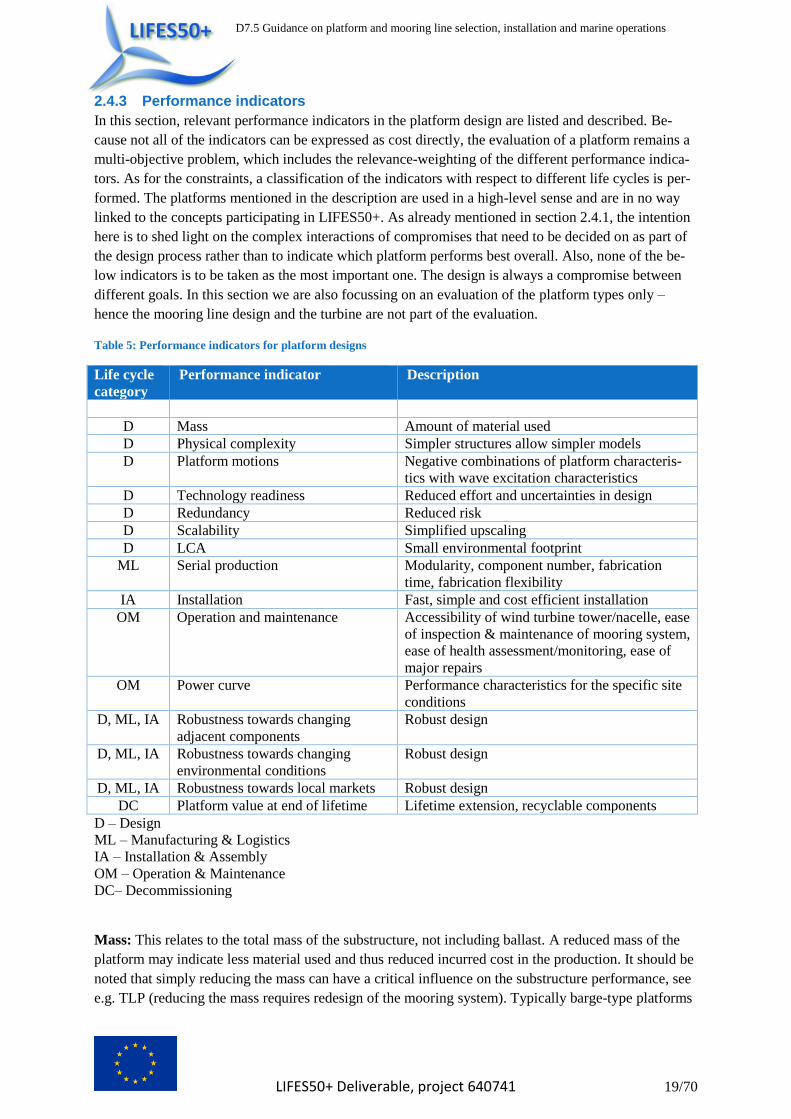
2.4.3 Performance indicators
In this section, relevant performance indicators in the platform design are listed and described. Be-
cause not all of the indicators can be expressed as cost directly, the evaluation of a platform remains a
multi-objective problem, which includes the relevance-weighting of the different performance indica-
tors. As for the constraints, a classification of the indicators with respect to different life cycles is per-
formed. The platforms mentioned in the description are used in a high-level sense and are in no way
linked to the concepts participating in LIFES50+. As already mentioned in section 2.4.1, the intention
here is to shed light on the complex interactions of compromises that need to be decided on as part of
the design process rather than to indicate which platform performs best overall. Also, none of the be-
low indicators is to be taken as the most important one. The design is always a compromise between
different goals. In this section we are also focussing on an evaluation of the platform types only –
hence the mooring line design and the turbine are not part of the evaluation.
Table 5: Performance indicators for platform designs
Life cycle
category
Performance indicator Description
D Mass Amount of material used
D Physical complexity Simpler structures allow simpler models
D Platform motions Negative combinations of platform characteris-
tics with wave excitation characteristics
D Technology readiness Reduced effort and uncertainties in design
D Redundancy Reduced risk
D Scalability Simplified upscaling
D LCA Small environmental footprint
ML Serial production Modularity, component number, fabrication
time, fabrication flexibility
IA Installation Fast, simple and cost efficient installation
OM Operation and maintenance Accessibility of wind turbine tower/nacelle, ease
of inspection & maintenance of mooring system,
ease of health assessment/monitoring, ease of
major repairs
OM Power curve Performance characteristics for the specific site
conditions
D, ML, IA Robustness towards changing
adjacent components
Robust design
D, ML, IA Robustness towards changing
environmental conditions
Robust design
D, ML, IA Robustness towards local markets Robust design
DC Platform value at end of lifetime Lifetime extension, recyclable components
D – Design
ML – Manufacturing & Logistics
IA – Installation & Assembly
OM – Operation & Maintenance
DC– Decommissioning
Mass: This relates to the total mass of the substructure, not including ballast. A reduced mass of the
platform may indicate less material used and thus reduced incurred cost in the production. It should be
noted that simply reducing the mass can have a critical influence on the substructure performance, see
e.g. TLP (reducing the mass requires redesign of the mooring system). Typically barge-type platforms

D7.5 Guidance on platform and mooring line selection, installation and marine operations
LIFES50+ Deliverable, project 640741 20/70
tend to have larger mass compared to the other platforms when using the same material configuration.
Also, concrete-material platforms typically tend to have a larger mass.
Physical complexity: Physically simple structures will enable simpler modelling, resulting in faster
and less conservative designs with lower uncertainty (e.g. the geometry of a spar allows the use of
simpler models than other concepts (e.g. star-shaped platforms)).
Platform motions: While platform motions in different degrees of freedom may reduce the loading on
the system, it is likely to have a negative influence on the system performance. Typically, the interplay
between the physical properties of the structures and the waves effect the platform performance, i.e.
platform natural frequencies or other wave excitation peaks in the wave spectrum likely lead to in-
creased motions. Making use of e.g. the wave cancellation effect may be beneficial to mitigate nega-
tive consequences. Different degrees of freedom should be considered.
For the platform pitch, small platform motions will result in small variances of the tower top motions
and thus in the power performance. A large pitch stiffness leads to an increased platform stability and
hence reduces tower top motions. However, high stiffness should not be regarded as an absolute bene-
ficial factor, e.g. having the pitch period in the frequency range of the waves can increase fatigue
loads. For the platform surge, large motions may negatively impact the loads on mooring lines and
the dynamic cable. Typically, barge platforms tend to show larger horizontal displacements than other
platforms, while TLPs or platforms with taut mooring systems tend to show small displacements. For
the platform yaw, platforms with small yaw stiffness due to the geometric setup or eccentricity of the
rotor blades may lead to increased motions.
Potentially, some of the induced loads may be reduced by active or passive load mitigation systems
which will enhance the power performance and reduce the loading of the system (e.g. unit positioning
at a predefined angle, individual pitch control, etc.). This will come at some cost, as the applied sys-
tems may need to be maintained. Also, if a component failure of the load mitigation system is a critical
issue, redundancy or sufficient safety levels need to be considered in the design. At this point in time
load mitigation systems are not typically implemented in FOWTs, but could be more common in fu-
ture designs.
Technology readiness: The technology readiness level (TRL) of a given platform helps to reduce the
design effort and risks as well as the uncertainty of the costs and investors’ confidence. There are dif-
ferent ways to derive the TRL. A means for indication of the TRL could be the number of installed
platforms of this system in the form of prototypes and pre-commercial farms. To this point full-scale
FOWT systems based on spar and semi-submersible platforms have been deployed.
Redundancy (station keeping system): A redundant station keeping system reduces the risk level of
the system (and thus insurance costs) and allows the station keeping system to be designed for a nor-
mal safety class. Without a redundant station keeping system, the consequences of failures need to be
considered in the design. These can be critical, if the considered platform is not self-stable (typically
TLP substructures for floating wind applications).
Scalability: The same concept may have to be adapted for different wind turbines sizes. In that case,
considerations for different parameters may be important and have to be evaluated case-specifically.
For example, if the concept’s dimension is generally large and the dimension is a relevant factor due to
constraints in the production, concepts with smaller overall dimensions have an advantage (e.g. TLP
substructures). On the other hand, larger structures may not require a significant redesign of the sub-
structure, but simple upscaling by means of enlarging the dimensions, which results in a reduced up-
scaling effort.

D7.5 Guidance on platform and mooring line selection, installation and marine operations
LIFES50+ Deliverable, project 640741 21/70
LCA: The life cycle assessment (LCA) can be used as a measure of how “green” the platform is. The
environmental footprint of concrete platforms and synthetic mooring lines may be less beneficial,
when looking at recycling capabilities.
Serial production: If a large number of units is to be produced, several specific items become im-
portant:
- Modularity: A high ratio of modular components of a structure indicates enhanced manufac-
turing capabilities (flexibility towards supply chain, manufacturing yard, i.e. industrialized
manufacturing) as well as simpler transportation and, consequently, reduced costs. While in
general all platform concepts can be modularized, it tends to be easier to realize this with steel
structures. Large concrete structures tend to be more difficult to design in a modular manner.
- Component number: A small number of components/parts and thus joints/connections re-
quires less time for manufacturing (e.g. welds, connecting flanges) and reduces expected
maintenance costs (e.g. inspection). This is comparable to the selection of jacket substructures
and monopiles, where both platforms are highly modular, but monopiles have an advantage
with respect to the number of components due to the reduced number (and complexity) of
welding connections.
- Fabrication time: A smaller fabrication time means a higher flexibility of the overall produc-
tion and faster project delivery. To reach this, the platform design needs to allow a high level
of automation and use of assembly lines during the production.
- Fabrication flexibility: A platform that can be fabricated at different sites and is not limited
to a certain harbour, workshop etc. will have a relative advantage, because it is less dependent
on given local conditions and possibly increased transportation cost. Additionally, simultane-
ous manufacturing at multiple facilities is possible.
Installation: The aim for a cost effective installation is that it all procedures can be performed fast, are
simple and inexpensive. Items that may have a significant influence on the installation performance of
a substructure are:
- Stability during transport: Stability during transport operations allows a more stable
transport and hence cost-effective transport of the platform. To achieve this, a lower centre of
gravity or a large second moment of water plane area is beneficial.
- Installation time: An efficient installation due to optimized connection solutions or parallel-
ized installation procedures will enable a fast installation and early power production.
- Required Infrastructure at harbour: A concept that can be assembled at any harbour can
freely choose the assembly harbour, which will reduce the time of installation. Also, cost are
reduced due to availability of more options to choose from. Items that come into play for the
assembly harbour are potentially platform draft, wind turbine assembly procedure, modularity,
launching mechanism, storage requirements, and maximum weights & dimensions of compo-
nents (i.e. lifting requirements).
- Also, the requirements regarding installation vessels, as well as the mooring and anchoring
system may be of importance.
Operation and maintenance: During the system life, efficient execution of inspection, maintenance
and repair operation is desired. This overall goal can be divided into the following items:
- Accessibility of wind turbine tower/nacelle: A good accessibility of the tower and rotor-
nacelle assembly (RNA) enables quick and efficient maintenance manoeuvres. This can be re-
alized by smaller platform motions due to improved dynamic behaviour and large deck areas.

D7.5 Guidance on platform and mooring line selection, installation and marine operations
LIFES50+ Deliverable, project 640741 22/70
- Ease of inspection and maintenance of mooring system: A good accessibility of the moor-
ing lines enables quick and efficient maintenance manoeuvres (e.g. tow back to harbour).
Above water mooring connection and access from deck support accessibility and maintenance.
Smaller mooring line lengths allow faster inspections. Adjustments to allow simple re-
tensioning procedures, sensors for condition monitoring are of advantage. Overall very specif-
ic point to the design and not related to a specific platform type.
- Ease of health assessment/monitoring: If it is possible to easily track the structural health of
the system, the effort of scheduling and performing O&M tasks is reduced. The same applies
to on-site health monitoring. Overall very specific point to the design and not related to a spe-
cific platform type.
- Major repairs (e.g. change of blades)
Strategy for major repairs (on-site, tow in). Ease of disconnection process, vessel require-
ments. Challenging to find suitable heavy-lift crane vessels to allow on-site change of major
turbine components (especially for 10MW units), so tow-in is likely necessary, which may be
problematic for deep-draft structures.
Power curve: A good match of the mean measured and OEM performance characteristics for the spe-
cific site conditions is desired. For this, platforms with less motion tend to have less fluctuation in the
produced power. Smaller mean inclination of the platform also yield less cosine-losses in the power
output. The key to ensuring that the turbine characteristics are maintained is an adequately designed
controller.
Robustness towards changing components: A system that performs well with different wind tur-
bines / station keeping systems / electrical setups does not require a redesign and hence reduces uncer-
tainty.
Robustness towards changing environmental conditions: This is regarded as one of the key items
for a FOWT design. A system that performs well in different environmental conditions does not re-
quire a substantial redesign and hence reduces the uncertainty (e.g. with respect to expected loads and
motions). Robustness towards the following items can be considered of importance:
- Geotechnical considerations (including geophysics and bathymetry): Due to site specific
locations it may be necessary to select different anchoring systems. Also, the water depth may
vary for different turbines within a wind farm or even the same turbine but different anchors.
- Metocean conditions
o Wind: In addition to different maximum wind speeds, different classes of turbulence
may have to be expected for different sites or locations within a wind farm. Also,
more than one wind directions may be dominant, so that an ideal orientation of the
platform may not be possible. Wind farm effects have not been considered in detail
for FOWTs up to this point but can be expected to be an important consideration in
the future.
o Waves: Different wave heights and especially wave period ranges (or even swell
waves) may be present. As wind and waves may not come from one dominant direc-
tion, but vary in directionality, this could lead to a large range of wind-wave misa-
lignments.
o Currents: Wind driven and tidal currents may be present at a site. Different current
profiles, with varying directions, are possible. Vortex-induced-vibrations may also
have to be considered.

D7.5 Guidance on platform and mooring line selection, installation and marine operations
LIFES50+ Deliverable, project 640741 23/70
o Tidal ranges: Tides lead to site specific temporary changes in the water depth with
varying magnitude for different locations. This could have some impact on the preten-
sion of TLPs and thus have a larger effect on this platform type.
- Extreme weather events: Hurricanes, typhoons, ice, earthquakes, etc. may be present at the
chosen site.
- Marine growth: For different locations, varying depth ranges and different compositions of
marine growth are possible.
- Weather window: A large variety of available time for installation as well as O&M proce-
dures is to be expected for different areas of deployment.
- Climate: For different locations, a change in the climate (in addition to the abovementioned
parameters) may lead to the necessity of redesigning specific components, e.g. due to in-
creased temperatures.
Robustness towards local markets: Local regulations (on materials, damage stabilites, etc.), supply
chain, vessel availability, subsidies for local content, local economy (e.g. fisheries), environmental
concerns, may also impact the decision making for the site specific design.
Platform value at end of lifetime: Platforms that are likely to be of value after their designated life-
time may be more desirable. This can be achieved by e.g. lifetime extension. Platforms that can poten-
tially be used beyond their designed lifetime are to be higher valued. This may be due to more con-
servative design, application of advanced design methods or materials, etc. Other options to achieve a
value after the design lifetime is the use of recyclable materials as well as accounting for measures that
allow simple decommissioning procedures.
2.5 10 MW specific issues A part of this work is the investigation of the influence of increasing size of wind turbines (and hence
the platform size) on the concept selection. In order to do this, the same questionnaire as mentioned in
section 2.4 was evaluated to determine relevant items which could change with increasing system size.
Next to this, key results of the upscaling workshop as part of the LIFES50+ deliverable 1.6 (Pérez, et
al., 2017) are included in this report to provide an overview of items to be considered when upscaling
a system. Finally, as part of this work, a simulation study was performed to analyse the loading of
different substructures with 10 MW systems. This was compared with a previous study performed
with 5 MW systems and evaluated for differences.
2.5.1 Upscaling considerations and challenges for large wind turbines
New challenges for floating substructures due to increasing size of wind turbines are summarized here
based on results of the above mentioned questionnaire and the LIFES50+ WP1 workshop as docu-
mented in (Pérez, et al., 2017).
From WP1 design experiences, the tower design and wind turbine control can be seen as the main
challenges for the design. For the tower, upscaling could possibly increase 3P excitation. Thus, con-
cept designers will likely need to adopt different solutions in order to avoid an overlap with this fre-
quency in the design of the system. Both soft-stiff and stiff-stiff designs can be considered as was done
in this project. For large wind turbines, the tower design should be addressed in close collaboration
with the WTG manufacturer, taking into consideration the control algorithm to be used for the system.
From LIFES50+ experience, the same design procedures and modelling used for smaller wind turbines
are also valid for larger ones. The concern is that the nonlinear scaling of diffraction effects and the
mooring line loads may be a critical item as mentioned in (Strach-Sonsalla, et al., 2016), was not re-

D7.5 Guidance on platform and mooring line selection, installation and marine operations
LIFES50+ Deliverable, project 640741 24/70
flected by the LIFES50+ experience. The scaling of physical properties did not have detrimental ef-
fects on the overall concept design and the design procedures. Also, for the LIFES50+ designs, the
design driving load cases remained the same as those for the floaters designed for smaller turbines.
However, some load cases may need to be addressed in more detail, which might require a higher
quality of the environmental data for a given site.
Logistics for serial production is regarded as a potential bottleneck as WTGs continue to increase in
size. Modularization of the floating structure is considered a key factor in the path for the industrializa-
tion (including serial manufacturing) of large floating wind turbines and for large wind farms. The
increased component sizes may make it impossible to fabricate and/or assembly them in certain ship-
yards/harbours. The final assembly of the platform, with the inclusion of the WT and tower erection, is
also detected as a possible bottleneck for large scale wind turbines, due to the limited availability of
lifting devices which can handle the required weights up to the required heights.
More related to the different concepts, the turbine spacing is increased with a larger rotor diameter
which means that upscaling eases footprint restrictions for a given concept (e.g. catenary systems).
However, concrete structures may at some point become excessively large.
Aspects not considered in detail in LIFES50+, like wind farm layout, turbulence modelling and power
production can also significantly influence the floater and mooring line design and should be consid-
ered more closely when facing detailed design stages. In general, larger systems result in larger plat-
forms and turbines relative to waves, wind and ice, which generally increases the number of potential
deployment sites.
2.5.2 Load specific evaluation of platform types
A simulation study was performed in order to investigate the wind turbine loading for a given site
using two different substructures. Simulation of an onshore wind turbine were used as a means for
normalization. The floating DTU 10 MW reference turbine (Borg, et al., 2015) was positioned on top
of the DTU TLP (made available for this work by DTU and presented in (Bredmose, et al., 2015),
(Pegalajar Jurado, et al., 2016), (Heilskov, et al., 2016)) and the Stuttgart Wind Energy (SWE) Tri-
pleSpar (Lemmer, et al., 2016). In order to simplify the comparison, the same tower and controller was
used for both platforms. While a different tower geometry may reduce the loads, it also complicates a
direct comparison, when an onshore turbine is to be used as a reference. A new controller was estab-
lished and used for both floating substructures. Using the same controller for both systems facilitates a
direct comparison and was possible in this study because the pitch natural frequency of the SWE Tri-
pleSpar is similar to the surge natural frequency of the DTU TLP. This way, the FOWT controller for
both platforms required the filtering of the same frequency range. The considered site was Site A -
Golf de Fos (most realistic for development of FOWT wind farms) for which the design load cases
(DLCs) 1.2, 1.4, 1.6, 6.1 were evaluated as described in (Krieger, et al., 2015). Preparatory simulations
were also performed in order to determine the platform specific orientation at the site, worst case di-
rection for wind and wave loading and wind speed dependent steady state conditions that were used as
initial conditions for the simulations. The results of the different load cases are discussed in the follow-
ing paragraphs, concluding with a global evaluation.
The following abbreviations were defined and used for the evaluated positions (mostly adopted from
FAST):
- TwrBsM: resulting tower base bending moment
- TwrBsYawM: tower base yaw moment
- TTBrMxn: tower top fore-aft bending moment

D7.5 Guidance on platform and mooring line selection, installation and marine operations
LIFES50+ Deliverable, project 640741 25/70
- TTBrMyn: tower top side-side bending moment
- TTBrMzn: tower top yaw bending moment
- RootFlapM: blade root flapwise bending moment
- RootEdgeM: blade root edgewise bending moment
- PtfmSurge: Surge displacement of platform
- PtfmSway: Sway displacement of platform
- PtfmHeave: Heave displacement of platform
- PtfmRoll: Roll displacement of platform
- PtfmPitch: Pitch displacement of platform
- PtfmYaw: Yaw displacement of platform
Note that no load evaluation is performed for any location below the tower base as the loads on the
onshore wind turbine were always considered as the reference values. Due to the fundamental differ-
ences of the investigated substructure concepts, a comparison of the platform or mooring line loads
would not lead to any practical conclusions. Also, it is highlighted that the same wind environment
was considered for both the onshore and offshore calculations. For the DLC1.6 reference case this
implies the same loading as for DLC 1.2 for onshore calculations (similar to the onshore DLC1.1).
The loads are normalized using onshore reference simulations, as has been done previously in
(Jonkman, et al., 2011).
DLC 1.2: Figure 5 shows the results of DLC1.2 calculations for different wind speeds. The same wind
distribution (i.e. according to Gulf de Fos design basis) has been used for the onshore and floating
conditions. Damage equivalent loads (DELs) were calculated using rainflow counting and a SN-curve
slope of . The fatigue load case with the 10 MW shows similar results as has been presented in
previous studies for smaller systems, e.g. (Matha, 2010), (Robertson, et al., 2011). For wind speeds
with significant damage contribution (i.e. around rated wind speed and higher) the tower fatigue loads
show a significant increase compared to the onshore system. This underlines that a site-specific design
of the tower is needed also for floating wind turbines. The fatigue loading of the rotor shows no signif-
icant increase in the loading (<10% for relevant wind speeds), when the turbine is positioned on any of
the two considered floating structures.
Figure 5: Mean sea-to-land DEL ratios from DLC 1.2 over wind speed
D7.5 Guidance on platform and mooring line selection, installation and marine operations
LIFES50+ Deliverable, project 640741 26/70
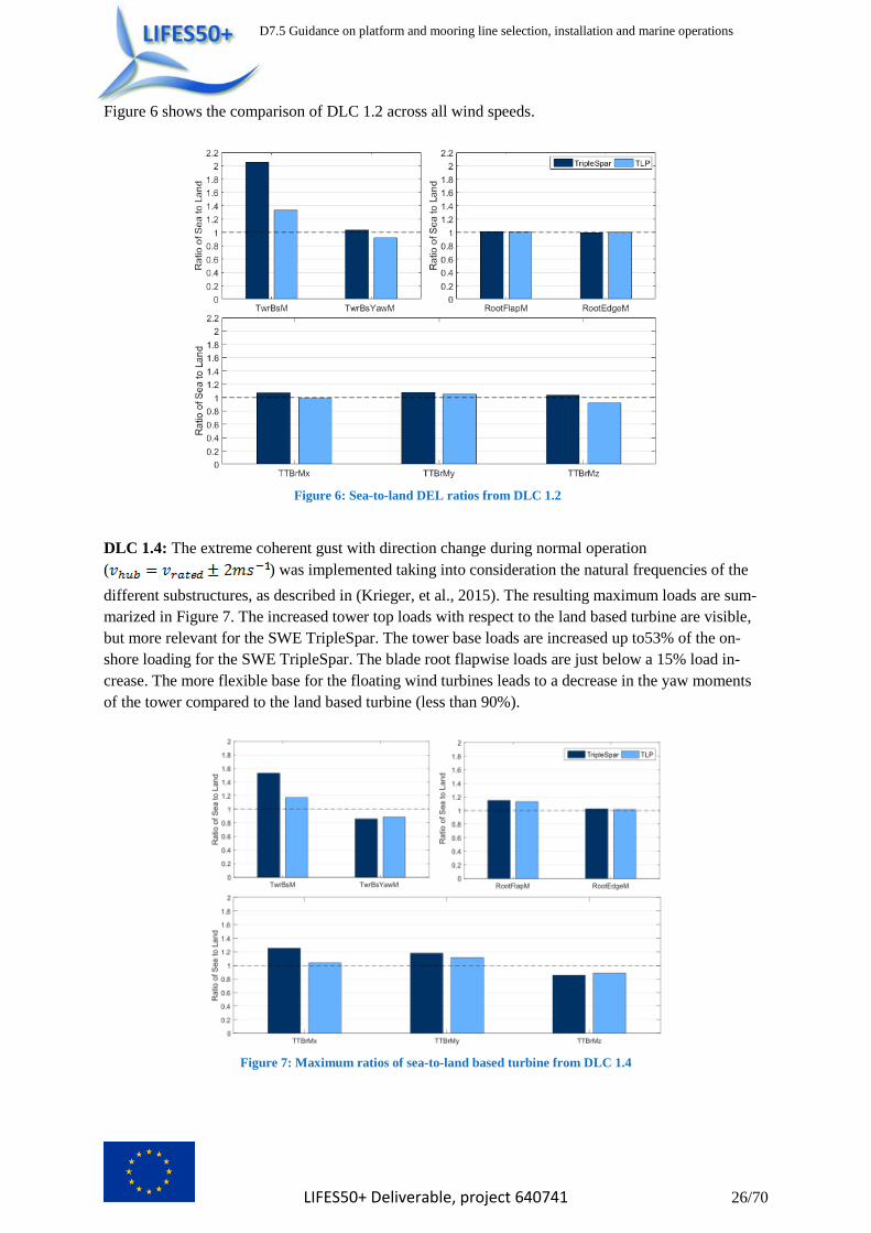
Figure 6 shows the comparison of DLC 1.2 across all wind speeds.
Figure 6: Sea-to-land DEL ratios from DLC 1.2
DLC 1.4: The extreme coherent gust with direction change during normal operation
( ) was implemented taking into consideration the natural frequencies of the
different substructures, as described in (Krieger, et al., 2015). The resulting maximum loads are sum-
marized in Figure 7. The increased tower top loads with respect to the land based turbine are visible,
but more relevant for the SWE TripleSpar. The tower base loads are increased up to53% of the on-
shore loading for the SWE TripleSpar. The blade root flapwise loads are just below a 15% load in-
crease. The more flexible base for the floating wind turbines leads to a decrease in the yaw moments
of the tower compared to the land based turbine (less than 90%).
Figure 7: Maximum ratios of sea-to-land based turbine from DLC 1.4
D7.5 Guidance on platform and mooring line selection, installation and marine operations
LIFES50+ Deliverable, project 640741 27/70
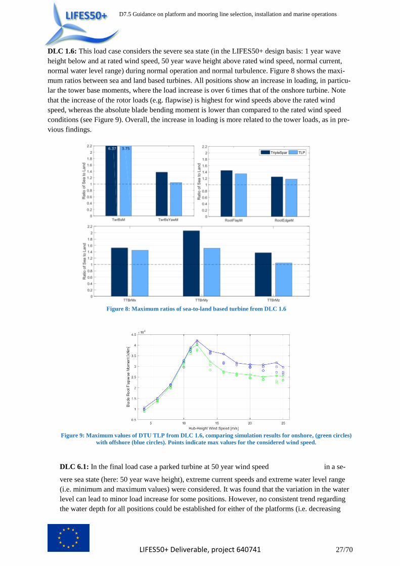
DLC 1.6: This load case considers the severe sea state (in the LIFES50+ design basis: 1 year wave
height below and at rated wind speed, 50 year wave height above rated wind speed, normal current,
normal water level range) during normal operation and normal turbulence. Figure 8 shows the maxi-
mum ratios between sea and land based turbines. All positions show an increase in loading, in particu-
lar the tower base moments, where the load increase is over 6 times that of the onshore turbine. Note
that the increase of the rotor loads (e.g. flapwise) is highest for wind speeds above the rated wind
speed, whereas the absolute blade bending moment is lower than compared to the rated wind speed
conditions (see Figure 9). Overall, the increase in loading is more related to the tower loads, as in pre-
vious findings.
Figure 8: Maximum ratios of sea-to-land based turbine from DLC 1.6
Figure 9: Maximum values of DTU TLP from DLC 1.6, comparing simulation results for onshore, (green circles)
with offshore (blue circles). Points indicate max values for the considered wind speed.
DLC 6.1: In the final load case a parked turbine at 50 year wind speed in a se-
vere sea state (here: 50 year wave height), extreme current speeds and extreme water level range
(i.e. minimum and maximum values) were considered. It was found that the variation in the water
level can lead to minor load increase for some positions. However, no consistent trend regarding
the water depth for all positions could be established for either of the platforms (i.e. decreasing

D7.5 Guidance on platform and mooring line selection, installation and marine operations
LIFES50+ Deliverable, project 640741 28/70
water depth may or may not lead to an increase in loading). Again, an increase in loading ratios for
all evaluated positions could be observed, this time even larger when compared with the previous
load cases. However, due to the lower absolute loads compared to DLC 1.6, for most positions,
this load case did not mark the critical condition for either one of the platforms (see Table 6, Table
7). Figure 10shows the maximum sea-to-land ratios for DLC 6.1 as well as the maximum observed
displacements in the 6 degrees of freedom. It can be seen that staying within displacement and
SLS criteria is more likely to affect the SWE TripleSpar platform than the DTU TLP.
Figure 10: Left: Maximum ratios of sea to land based turbine from DLC 6.1; Right: Maximum values of platform
motions from DLC 6.1
Table 6 and Table 7 show the maximum absolute ultimate loads for the different platforms and the
different load cases. The load case for each position with the largest loads is marked in dark blue. If
another load case generated close to the same loads (i.e. within 25%), it was marked in light blue. It
can be observed that for the chosen site, platforms and evaluated load locations, there is no difference
in the critical environmental conditions between the floating substructures analysed, apart from in-
creased flap bending loads for the SWE TripleSpar in DLC 1.4.
Table 6: Maximum values of DTU TLP in ultimate load cases
DLC 1.4 DLC 1.6 DLC 6.1
Tower base bending moment [kNm] 183 800 343 270 213 770
Tower base yaw moment [kNm] 24 680 17 720 3 670
Tower top bending moment [kNm] 18 971 25 760 23 730
Blade flapwise ben-ding moment [kNm] 37 530 42 140 25 780
Blade edgewise ben-ding moment [kNm] 13 520 16 120 6 810
Table 7: Maximum values of SWE TripleSpar in ultimate load cases
DLC 1.4 DLC 1.6 DLC 6.1
Tower base bending moment [kNm] 302 520 412 550 269 350
Tower base yaw moment [kNm] 34 610 17 550 4 345
Tower top bending moment [kNm] 34 955 27 780 24 420
Blade flapwise ben-ding moment [kNm] 53 700 42 860 28 530
Blade edgewise ben-ding moment [kNm] 14 310 16 720 7 661
Dis-
plac
eme
nt
[m]
Dis-
plac
eme
nt
[°]

D7.5 Guidance on platform and mooring line selection, installation and marine operations
LIFES50+ Deliverable, project 640741 29/70
Overall, when using the same tower design, there are increased loads for the TripleSpar compared to
the TLP. Also, the TripleSpar is more sensitive towards the Gust events as described in D1.4. DLC 1.6
does not seem to have a high importance for both substructures. For both platform types, the tower
needs to be redesigned (larger tower weights are to be expected for semi-submersibles due to the in-
creased tower loads. This goes in line with the fact that for the LIFES50+ public concepts from D4.2
(see (Wei, et al., 2017)), the tower weight of the semi-submersible platform is almost 3 times as high
as the one for the TLP). Also, limitations on displacements are more likely to affect the design of
semi-submersibles than the TLP. Rotor loads should be revaluated for both platform types even
though they do not show a significant change in magnitude when comparing offshore with onshore
loads (this is due to the relatively low influence of waves on the RNA loads).
3 Design of the station keeping system
3.1 Introduction The aim of the mooring line system is (1) to keep the floating substructure within a specified limit
from its reference position (i.e. control directional heading and limit maximum excursion defined by
dynamic power cable or wind farm setup) and (2) to provide a certain portion of stability to the float-
ing substructure. Assuming a substructure type (TLP, semi-sub, barge) is already selected, the remain-
ing decisions to be made by the designer regarding the mooring line selection are summarized in this
chapter. The chapter starts out with the design process, where a general description of the mooring line
design process for spread and tension mooring lines is given in sections 3.3 and 3.4, respectively.
Spread mooring systems are used as a baseline. Differences in the design approach for spread mooring
systems are highlighted in section 3.4. Additionally, in the same way as for the platform concept selec-
tion an optimization problem is formulated for the mooring line selection in section 3.5, in order to
provide information on the constraints, design parameters and performance indicators to be considered
in the mooring line design process. Based on the experiences from the upscaling procedure performed
in LIFES50+, the challenges expected from large wind turbines and upscaling procedures are summa-
rized in section 3.6. Finally, an overview of the risk considerations in the design of station keeping
system is given in section 3.7.
3.2 General Design Procedure Typically catenary mooring systems are designed with the main target of being compliant with the
motions of the floating substructure. The substructure motions in a given sea state are primarily domi-
nated by motions around the wave frequency, with the motions increased for waves closer to the natu-
ral frequencies of the substructure. Most substructure types for FOWTs are designed to have natural
periods out of the relevant range of wave frequencies (where most of the energy in the site wave spec-
trum is located), however for some types such as TLPs (at low wave periods / 3-5s) and barge-type
floaters (around peak spectral wave periods / 8-12s), avoiding such coinciding of natural FOWT peri-
ods with wave periods of relevant energy content is not always possible. For such designs, however,
typically either the damping is large enough in order to limit the increase in motion amplitudes in such
resonance conditions, or the resulting ultimate and/or fatigue loads are not design critical.
Floating substructures are often exhibiting large displacement, for FOWTs primarily in surge direc-
tion. A viable mooring design should be performed in order to fulfil its main purpose of station keep-
ing by being compliant and not forcefully restraining the translational motions of the floater. Mooring
systems only restrain motions for TLP designs, and here mostly only in heave direction (allowing for

D7.5 Guidance on platform and mooring line selection, installation and marine operations
LIFES50+ Deliverable, project 640741 30/70
inverted pendulum motions). However some TLP designs with cross-tendons (e.g. GICON’s SOF TLP
design) also restrain motions in pitch, roll and yaw to most extent
The actual design procedure utilized for FOWT mooring and TLP system designs cannot be general-
ized, with substructure designers following often individual approaches developed over time and expe-
rience in order to come up with an optimal design. On a high level however, most approaches share a
common procedure, as e.g. outlined by Kim (Kim, et al., 2014) and shown in Figure 11 and described
in Table 8. For TLP FOWTs, Bachynski (Bachynski, 2014) provides a good account of the particular
design procedures applied for tendon systems. Other accounts for design methodologies for station
keeping systems in floating wind are provided by Masciola in a book edited byCruz (Cruz, et al.,
2016).
Step Task
1. Definition of floating substructure and
design constraints and targets (e.g.
metocean conditions, max. heel angle,
etc.)
2. Linear analysis of floater (RAOs)
3. Initial/conceptual mooring design based
on simplified (mostly quasi-static) ap-
proaches
4. Floating stability check (static equilibri-
um)
5. Design load determination by load case
simulation in time domain (typically a
combination of global fully coupled FOWT
analyses and detailed de-coupled mooring
analysis)
6. Check of characteristic design tension
against limit states (and slacking for
TLPs)
Figure 11: Catenary mooring design, (Kim, et al., 2014) Table 8 General mooring design steps
From related design works in LIFES50+, a two-step / decoupled design approach for mooring lines is
recommended: (1) calculate movements and forces from coupled simulation and use these for (2) de-
tailed mooring line design using higher-order hydrodynamics that cannot be considered in coupled
simulation with feasible time.
3.3 Design methodology for a spread mooring system
3.3.1 Functional principle
3.3.1.1 Catenary mooring system
The upper end of the mooring chain is attached to the floater, the lower end is attached to an anchor. In
the initial floater position a significant part of the mooring chain lies horizontally on the seabed. When
the floater is moved in the horizontal direction due to static and dynamic environmental loads the
D7.5 Guidance on platform and mooring line selection, installation and marine operations
LIFES50+ Deliverable, project 640741 31/70
shape of the mooring chain changes: the free hanging part (catenary) is tightened and raised, which
results in an increased horizontal restoring force. Furthermore, the lower part of the chain is raised
from the seabed, increasing the effective weight of the mooring line and, thus, the vertical reaction
force on the floater.
As the lower end of the mooring chain lies on the seabed, it is possible to use drag anchors for catena-
ry mooring systems.
3.3.1.2 Taut / semi-taut spread mooring systems
Taut and semi-taut mooring systems are often composed of synthetic fibre ropes, steel wire ropes or
are hybrid solutions (e.g. synthetic fibre ropes + chains). The upper end of the mooring line is con-
nected to the floater and the lower end to the anchor, the mooring line is taut between these two points.
The shape of the mooring line does not change significantly with floater offset, hence, the restoring
characteristic of these mooring systems strongly depends on line elasticity and general dimensions of
the mooring system (line angles, line length, etc.).
In taut / semi-taut spread mooring systems the line uplift angle at the anchor point is > 0°, hence drag
anchors are not suitable for this mooring type. Anchor piles are mainly used. However, in hybrid sys-
tems heavy chains may be used in the lower part of the line in order to reduce the uplift angle, so that
drag anchors can be used.
3.3.2 Rules & standards
A number of classification societies have issued FOWT specific standards and guidelines, which cover
– among other topics – the design of station keeping systems. In general, these documents adopt the
requirements on the station keeping systems for oil and gas (O&G) floating structures defined in the
respective standards (class rules, API, ISO) and combine them with wind turbine specific requirements
(IEC 61400-3).
A selection of relevant rules and standards are provided below (this list does not claim to be compre-
hensive, other rules and standards for station keeping system design also exist):
- FOWT specific documents:
o DNV-OS-J103, Design of Floating Wind Turbine Structures
o BV-NI572, Classification and certification of floating offshore wind turbines
o ABS Pub 195, Floating Offshore Wind Turbine Installations
o ABS Pub 206, Global Performance Analysis for Floating Offshore Wind Turbine In-
stallations
o ClassNK, Guidelines for Offshore Floating Wind Turbine Structures
- General floating structures and station keeping systems (O&G):
o API RP 2FPS, Recommended Practice for Planning, Designing, and Constructing
Floating Production Systems
o API RP 2SK, Design and Analysis of Station keeping Systems for Floating Structures
o ISO 19904-1, Petroleum and natural gas industries - Floating offshore structures,
Part 1: Monohulls, semi-submersibles and Spars
o ISO 19901-7, Petroleum and natural gas industries - Specific requirements for off-
shore structures, Part 7: Station keeping systems for floating offshore structures and
mobile offshore units
o ABS Pub 82 (FPI Rules), Rules for building and classing floating production installa-
tions

D7.5 Guidance on platform and mooring line selection, installation and marine operations
LIFES50+ Deliverable, project 640741 32/70
o DNV GL-ST-0126, Design of wind turbine support structures
o DNVGL-OS-C103, Structural design of column stabilised units – LRFD method
o DNVGL-OS-C105, Structural design of TLPs – LRFD method
o DNVGL-OS-C106, Structural design of deep draught floating units – LRFD method
o DNVGL-OS-E301, Position mooring
o BV-NR571, Classification of column stabilized units
o BV-NR493, Classification of mooring systems for permanent offshore units
o Lloyds Register, Rules and Regulations for the Classification of Offshore Units
Furthermore, specific documents are available for the components of the mooring system (chains, steel
wire ropes, synthetic fibre ropes, and anchors).
In Table 9 the major differences between O&G and FOWT requirements are addressed.
Table 9: Major differences between O&G and FOWT requirements
No O&G FOWT
1 ULS (survival) condition defined by envi-
ronmental conditions with 100y return
period.
ULS is defined as the combined load or com-
bined load effect, whose return period is 50
years. Therefore 50y environmental conditions
are used.
2 Number of relevant ULS conditions rela-
tively small, mainly covering combinations
of 100y environmental parameters (signifi-
cant wave height, wave period, wind-
speed, current).
Most severe loading condition is not necessarily
the 50y storm condition with idling WTG. All
relevant conditions (full spectrum of the design
load cases DLCs adopted from IEC 61400-3) need
to be investigated. This may lead to an extensive
scope of load simulations necessary compared
to O&G.
3 Different calculation methods for mooring
lines are possible, from quasi-static to
coupled dynamic analyses. The accuracy of
the analysis method is accounted for in
different safety factors to be applied.
Applicability of the quasi-static approach for
FOWT is questioned, dynamic effects from the
WTG are deemed to be important. Therefore,
dynamic analysis methods shall be used for
mooring design, unless it can be shown that
dynamic effects are negligible
4 Generally in O&G redundant mooring sys-
tems are required.
Non-redundant systems are possible. Higher
safety factors have to be then applied. E.g. 3-line
spread mooring systems are possible.
The items 2 and 3 from Table 9 require a significant computational effort needed to design a mooring
system for a FOWT. For practical application an agreement with the certification body will need to be
found in this regard.
In the following, DNVGL rules will be taken as the basis for design of the station keeping system:
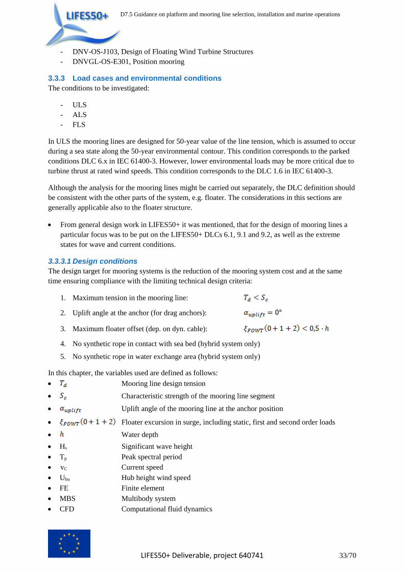
D7.5 Guidance on platform and mooring line selection, installation and marine operations
LIFES50+ Deliverable, project 640741 33/70
- DNV-OS-J103, Design of Floating Wind Turbine Structures
- DNVGL-OS-E301, Position mooring
3.3.3 Load cases and environmental conditions
The conditions to be investigated:
- ULS
- ALS
- FLS
In ULS the mooring lines are designed for 50-year value of the line tension, which is assumed to occur
during a sea state along the 50-year environmental contour. This condition corresponds to the parked
conditions DLC 6.x in IEC 61400-3. However, lower environmental loads may be more critical due to
turbine thrust at rated wind speeds. This condition corresponds to the DLC 1.6 in IEC 61400-3.
Although the analysis for the mooring lines might be carried out separately, the DLC definition should
be consistent with the other parts of the system, e.g. floater. The considerations in this sections are
generally applicable also to the floater structure.
From general design work in LIFES50+ it was mentioned, that for the design of mooring lines a
particular focus was to be put on the LIFES50+ DLCs 6.1, 9.1 and 9.2, as well as the extreme
states for wave and current conditions.
3.3.3.1 Design conditions
The design target for mooring systems is the reduction of the mooring system cost and at the same
time ensuring compliance with the limiting technical design criteria:
1. Maximum tension in the mooring line:
2. Uplift angle at the anchor (for drag anchors):
3. Maximum floater offset (dep. on dyn. cable):
4. No synthetic rope in contact with sea bed (hybrid system only)
5. No synthetic rope in water exchange area (hybrid system only)
In this chapter, the variables used are defined as follows:
Mooring line design tension
Characteristic strength of the mooring line segment
Uplift angle of the mooring line at the anchor position
Floater excursion in surge, including static, first and second order loads
Water depth
Hs Significant wave height
Tp Peak spectral period
vC Current speed
Uhu Hub height wind speed
FE Finite element
MBS Multibody system
CFD Computational fluid dynamics
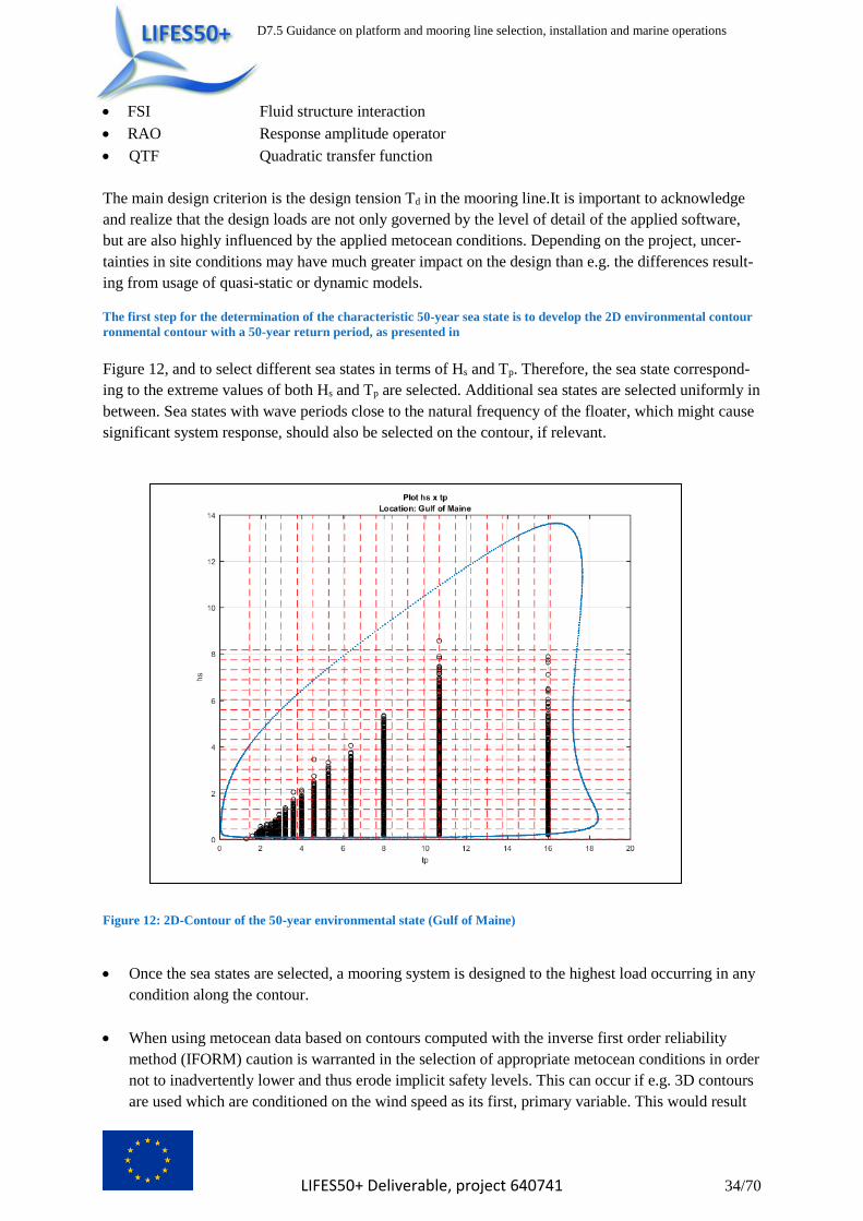
D7.5 Guidance on platform and mooring line selection, installation and marine operations
LIFES50+ Deliverable, project 640741 34/70
FSI Fluid structure interaction
RAO Response amplitude operator
QTF Quadratic transfer function
The main design criterion is the design tension Td in the mooring line.It is important to acknowledge
and realize that the design loads are not only governed by the level of detail of the applied software,
but are also highly influenced by the applied metocean conditions. Depending on the project, uncer-
tainties in site conditions may have much greater impact on the design than e.g. the differences result-
ing from usage of quasi-static or dynamic models.
The first step for the determination of the characteristic 50-year sea state is to develop the 2D environmental contour
ronmental contour with a 50-year return period, as presented in
Figure 12, and to select different sea states in terms of Hs and Tp. Therefore, the sea state correspond-
ing to the extreme values of both Hs and Tp are selected. Additional sea states are selected uniformly in
between. Sea states with wave periods close to the natural frequency of the floater, which might cause
significant system response, should also be selected on the contour, if relevant.
Figure 12: 2D-Contour of the 50-year environmental state (Gulf of Maine)
Once the sea states are selected, a mooring system is designed to the highest load occurring in any
condition along the contour.
When using metocean data based on contours computed with the inverse first order reliability
method (IFORM) caution is warranted in the selection of appropriate metocean conditions in order
not to inadvertently lower and thus erode implicit safety levels. This can occur if e.g. 3D contours
are used which are conditioned on the wind speed as its first, primary variable. This would result

D7.5 Guidance on platform and mooring line selection, installation and marine operations
LIFES50+ Deliverable, project 640741 35/70
in rather benign Hs and Tp conditions. Thus, care must be taken when selecting the actual data on
the contours, depending on considerations what the most relevant design driving parameters are.
Typically, using 2D Hs, Tp contours are a good initial assumption to determine governing ULS
conditions. The implications of the site conditions are aggravated by the highly nonlinear, progres-
sively stiffening restoring behaviour of mooring lines, particularly steel chains. Thus, the system
responds in the last part of the motion with an unproportionally higher tension and increases the
effect on ULS loads from uncertainties in site conditions.
Another known challenge from mooring design is how to determine the characteristic design loads.
Typically, following common recognized class societies (RCS) standards, a statistical database from
established tension data is developed and design values are extrapolated based on probability distribu-
tions. DNVGL-OS-E301 in this respect provides detailed guidance on how this extrapolation should
be performed.
3.3.3.2 ULS in parked conditions (DLC 6.x)
- On the 50-year environmental 2D contour (Hs, Tp) the following sea states are selected:
1) maximum value of significant wave height Hs + corresponding wave peak period Tp
2) wave periods Tp near the eigenfrequency of the floater + corresponding Hs values
3) other points along the contour for sensitivity check
- For current speed vC the 50y value is applied.
- For wind speed Uhub the 50y value is applied.
3.3.3.3 ULS in operation (DLC 1.6)
- 50-year sea states with corresponding operational wind speeds
To determine these conditions, below an exemplary method is presented (other methods also are appli-
cable, see standards for details):
- The 50-year environmental 3D contour of (U10, Hs, Tp) is determined and the 2D contour (Hs,
Tp) corresponding to Uhub = WTG operational wind speeds (all relevant wind speeds, at least
cut-out, rated, around rated).
- On the extracted 2D contour (Hs, Tp) the relevant sea states are selected as described above in
Section 3.3.3.2.
- For current speed vC, the 10y value is applied.
- For wind speed Uhub, the operational wind speeds for the DTU 10 MW wind turbine are ap-
plied.
3.3.3.4 ALS (Damaged condition)
The ALS analysis is carried out with the same environmental loads as for the ULS analysis. In the ALS analysis one line of the mooring system is assumed to be damaged (i.e. missing). Furthermore, in the ALS condition lower load factors are applied compared to ULS.
3.3.3.5 FLS
Fatigue assessment is required for the design of the mooring system. The long term environment
should be represented by a number of discrete conditions. Each condition consists of a reference direc-
tion and a reference sea state characterised by a significant wave height, peak period, current velocity
and wind velocity. Based on sensitivity analyses and/or other considerations, the reference directions
for wind and wave and its combinations should provide a good representation of the directional distri-
bution of a long-term environment (in the studies within this project, 8-12 combinations of directions
were acceptable). The required number of reference sea states should be determined based on sensi-

D7.5 Guidance on platform and mooring line selection, installation and marine operations
LIFES50+ Deliverable, project 640741 36/70
tivity studies and/or other considerations. Fatigue damage prediction may be sensitive to the number of
sea states, and sensitivity studies may be necessary.
If a fatigue analysis based on time domain calculations and rainflow counting is not applied for FLS
analysis due to the often time-consuming calculations, DNVGL-OS-E301 proposes alternative meth-
ods such as the “combined spectrum approach”, which considers both wave-frequency and low-
frequency components to compute the characteristic damage. For the calculation of the line tensions
components due to wave-frequency motions, time domain analyses taking into account mooring line
dynamics are required. Low-frequency components of the line tensions can be derived from the quasi-
static analysis. However the applicability of this approach for a specific floating wind turbine and site
must be demonstrated by comparisons to rainflow counting methods.
3.3.4 Calculation methods
3.3.4.1 Design Tools
Mooring system models combine structural mechanics for the representation of the line itself with
hydrodynamics for computation of the external fluid forces and contact mechanics for the forces on
the line from line-seabed interaction. In general, the marine environment continually disturbs each part
of the mooring line by perturbation from surface waves, surface and subsurface currents, subsurface
turbulence, and internal waves. The line responds to these disturbances with drift motions and transla-
tional and rotational oscillations along with structural deformations. In addition gravitational forces
from the weight of the line in water are constantly forcing the line to assume a catenary shape. For
lines with parts resting on the seabed, the line-seabed interaction in terms of friction forces on the line
and damping must be considered as well, a problem where a wide variety of models exist (Inoue, et
al., 1994; Ong, et al., 2003). The resulting motion of the line in turn gives rise to motion of the plat-
form, i.e. both systems are in general coupled except for special built-in fairlead design features aim-
ing to decouple the systems. Numerical mooring system models can generally be divided into two
main categories: quasi-static and dynamic modelling approaches. Table 10 presents the two categories
and the different methods within these categories together with their typical implementation in inte-
grated aero-servo-hydro-elastic models.
Table 10: Categories of mooring modelling methodologies
Main Category Sub-category Common implementation
Quasi-static
Linearized representation of complete moor-
ing system (valid only for small displace-
ments) (Sandner, et al., 2012)
Linear stiffness matrix
Nonlinear force-displacement relationship
derived from either quasi-static or dynamic
models (averaged) (Cordle, et al., 2011)
3D-lookup-table with interpolation for complete
mooring system restoring force
3D-lookup-table with interpolation for each
individual mooring line restoring force
Analytical solution of implicit nonlinear
catenary equations (Jonkman, 2007)
Analytical subroutine
Dynamic Discretized finite element or finite-difference
approach with Morison or other potential
flow hydrodynamic force (Armendariz, et al.,
2011; Hall, 2013)
Various finite element formulations

D7.5 Guidance on platform and mooring line selection, installation and marine operations
LIFES50+ Deliverable, project 640741 37/70
Discretized multibody approach with Mori-
son or other potential flow hydrodynamic
force (Matha, et al., 2011)
Rigid or flexible connected multibody elements
Discretized FE/MBS with 3D CFD hydrody-
namic force (Chakrabarti, 2008)
Full 3D FSI (FE-CFD) implementation (currently
only applied for O&G structures)
In summary, except for quasi-static models, which do not represent the line structure itself, the struc-
tural mechanical representations used by dynamic models are lumped mass, rigid or flexible finite
segment, assumed modes or FE approaches. In case of quasi-static methods only the hydrostatics loads
acting on the mooring line are modelled, and in case of dynamic methods in addition the hydrodynam-
ic forces from waves and currents and line motion are represented by potential flow or CFD based
methods. Since a line is a slender cylindrical body, usage of Morison equation is suitable.
In O&G and floating wind industries, both quasi-static and dynamic models are used in the design. For
conceptual analyses, the quasi-static models offer a good and robust tool to investigate important
trade-offs and study a large variety of different systems. In the detailed design phase, ultimately dy-
namic mooring line models applied in time-domain simulations are primarily used. Here numerous
commercial software packages exist which are capable of high fidelity modelling of the mooring sys-
tems, with some of commercial packages now also being able to model the wind turbine to a sufficient
level of detail.
3.3.4.2 Quasi-static analysis
Tensions in the mooring lines at defined horizontal floater offset are calculated by static FE-analysis.
The considered floater offset includes:
1) Static offset due to static environmental loads (steady wind, steady current, mean wave
drift force) and steady turbine thrust if applicable.
2) Dynamic offset due to low-frequency motion (slowly varying oscillations) .
3) Dynamic offset due to wave-frequency motion .
The two dynamic offset components are referred to in DNVGL-OS-E301 (Ch. 2, Sc. 2.7.6) as the
characteristic offset , which is defined as the larger value of the following:
(2)
where either the maximum low-frequency offset is combined with the significant value of the wave-
frequency offset, or, the significant value of the low-frequency offset is combined with the maximum
wave-frequency offset.
The dynamic offset components are calculated using floater hydrodynamics (RAOs of motions, hy-
drodynamic added masses and damping coefficients, QTFs of wave drift forces) determined by means
of a hydro-mechanic frequency domain analysis (e.g. with a radiation/diffraction panel method).
As the motion behaviour of the floater is dependent on the stiffness of the mooring system, the hydro-
dynamic analysis of the floater should take this into account.

D7.5 Guidance on platform and mooring line selection, installation and marine operations
LIFES50+ Deliverable, project 640741 38/70
The quasi-static analysis method can be employed very efficiently for a concept design of the mooring
system. A large number of different mooring configurations can by analysed in a short time, which
makes this analysis method suitable for parametric studies.
However, for the certification of a permanent mooring system for a FOWT the quasi-static method
alone is not sufficient, as mooring line dynamics as well as the dynamic coupling between the mooring
system, the floater and the wind turbine are considered to be relevant.
As the quasi-static analysis method contains a number of uncertainties and simplifications, suitable
safety factors should be applied when using this method. Some of the documents listed in Section
3.3.2 provide safety factors, which account for the analysis method, however, the applicability of these
values for FOWTs is not always clear and should be rather understood as a guiding value. The safety
factor to be included in the quasi-static approach should be in the range of 1.7-2.0.
3.3.4.3 Dynamic analysis
For the detailed design of the mooring system for a FOWT a coupled dynamic analysis in the time-
domain should be performed. The dynamic analysis takes into account the time varying effects due to
mass, intertia, damping and fluid acceleration. Non-linear effects including line stretch (e.g. for syn-
thetic line material), change in line geometry, hydrodynamic loads on the line (often computed with
Morison equation, assuming the line is a slender cylindrical structure) and sea bottom effects can be
modelled.
For FOWTs the dynamic loads from the wind turbine are deemed to be important. Hence, in the dy-
namic analysis a coupled model (coupling between mooring lines, floater and wind turbine) should be
used. In each time step of the simulation the equation of motion including aero-dynamic loads on the
wind turbine, hydrodynamic loads on the floater and the mooring lines, inertia forces and restoring
forces of the mooring lines is solved.
For the time-domain analysis of mooring lines a number of commercial software packages, mainly
from O&G, are available.
In order to perform a coupled dynamic analysis, it is a common practice to calculate the aerodynamic
loads with a different software package (e.g. FAST) and to incorporate this loads into the finite ele-
ment model of the floater and the mooring system in each time step of the dynamic simulation. Updat-
ed structural positions and wind loads are exchanged between the corresponding solvers until numeri-
cal convergence is reached.
Dynamic analysis enables an accurate calculation of the maximum line loads in the ULS and ALS
conditions, extraction of the relevant cyclic load components for the FLS analysis as well as investiga-
tion of transient conditions (e.g. transition from the intact to the damaged condition, in which an
“over-shooting” of the final equilibrium position in the damaged condition is investigated).
3.3.5 Safety factors
The safety factors or load factors to be applied in the mooring line design generally depends on:
- Type of installation, i.e. temporary or permanent (FOWT is considered to be a permanent in-
stallation)
- Type of analysis (ULS or ALS)
- Redundancy of the mooring system
- Analysis method, i.e. quasi-static or dynamic analysis (usually, in FOWT specific guidelines
only factors for dynamic analysis are provided)
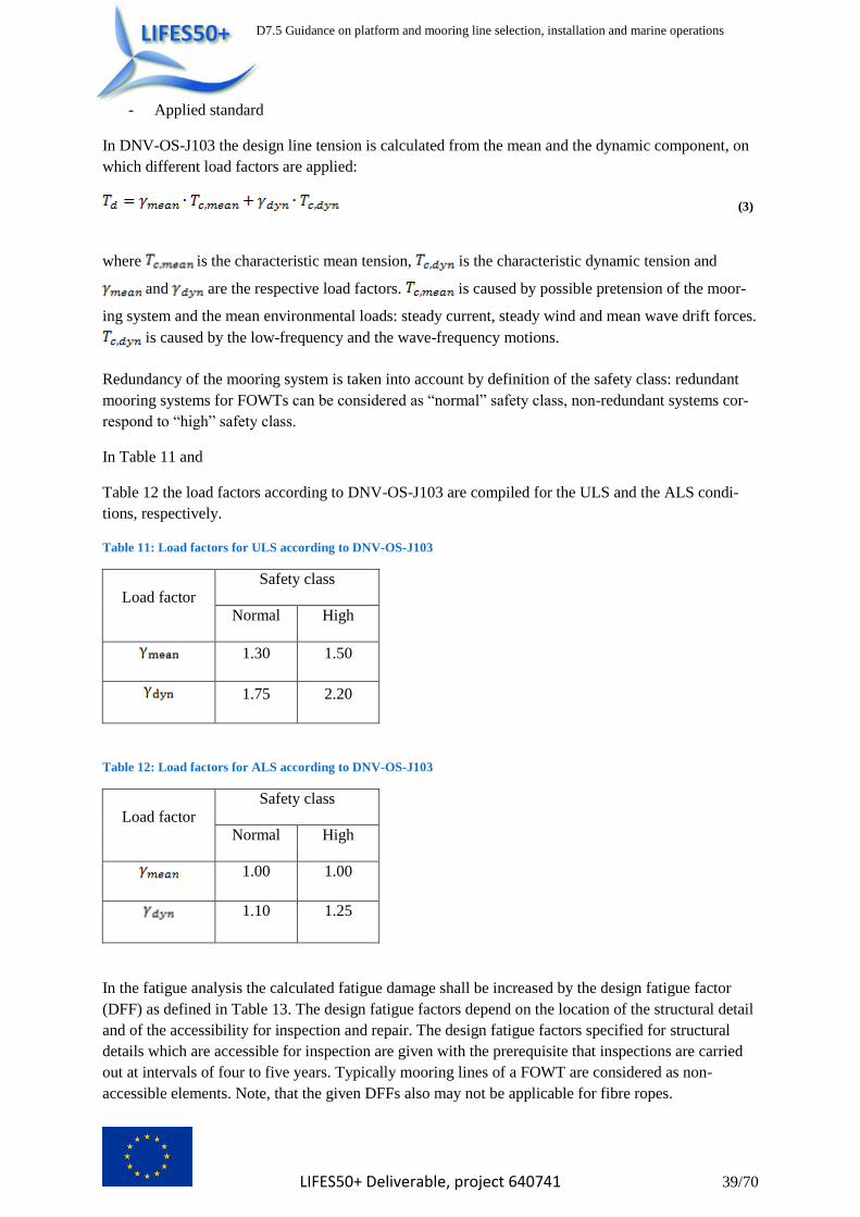
D7.5 Guidance on platform and mooring line selection, installation and marine operations
LIFES50+ Deliverable, project 640741 39/70
- Applied standard
In DNV-OS-J103 the design line tension is calculated from the mean and the dynamic component, on
which different load factors are applied:
(3)
where is the characteristic mean tension, is the characteristic dynamic tension and
and are the respective load factors. is caused by possible pretension of the moor-
ing system and the mean environmental loads: steady current, steady wind and mean wave drift forces.
is caused by the low-frequency and the wave-frequency motions.
Redundancy of the mooring system is taken into account by definition of the safety class: redundant
mooring systems for FOWTs can be considered as “normal” safety class, non-redundant systems cor-
respond to “high” safety class.
In Table 11 and
Table 12 the load factors according to DNV-OS-J103 are compiled for the ULS and the ALS condi-
tions, respectively.
Table 11: Load factors for ULS according to DNV-OS-J103
Load factor
Safety class
Normal High
1.30 1.50
1.75 2.20
Table 12: Load factors for ALS according to DNV-OS-J103
Load factor
Safety class
Normal High
1.00 1.00
1.10 1.25
In the fatigue analysis the calculated fatigue damage shall be increased by the design fatigue factor
(DFF) as defined in Table 13. The design fatigue factors depend on the location of the structural detail
and of the accessibility for inspection and repair. The design fatigue factors specified for structural
details which are accessible for inspection are given with the prerequisite that inspections are carried
out at intervals of four to five years. Typically mooring lines of a FOWT are considered as non-
accessible elements. Note, that the given DFFs also may not be applicable for fibre ropes.

D7.5 Guidance on platform and mooring line selection, installation and marine operations
LIFES50+ Deliverable, project 640741 40/70
Table 13: Selected Design Fatigue Factors (DFF) for FLS analysis according to DNV-OS-J103 (ref. to DNV-OS-J103,
Table 10 for full details)
Structural element
Safety class
Normal High
External, not accessible for inspection and
repair in dry and clean conditions 3.0 6.0
Non-accessible, not planned for inspec-
tion/repair 6.0 10.0
Note that according to DNVGL-OS-C105- “Structural design of TLPs - LRFD method” (Ch. 2, Sc. 6,
4.1.6), for TLPs other DFFs may need to be applied: “Tendon and tendon components shall have a
minimum design fatigue factor (DFF) of 10”.
3.4 Design methodology for a tension leg system
3.4.1 Functional principle
Although the first tension leg platforms (TLPs) in the O&G sector were very similar from a stabil-
ity/seakeeping point of view to a classic semi-submersible platform and were self-stable in any opera-
tional condition, the latest and most optimized design TLPs (the so called “seastar”) do not allow for
this stability without any external means or its mooring system during the operational stage. In this
sense, looking at the cost optimization at the floating offshore wind sector, most of the TLPs that are
being currently developed are, in general, not self-stable and their buoyancy is larger than the weight
at the still water draft. The bottom corners of the platform are connected with the seabed by means of
vertical tension legs (arrays of tendons). The difference in the buoyancy and the weight (surplus buoy-
ancy) is taken by the tension force in the tendons. The tension leg system (TLS) acts as station keeping
system ensuring platform stability as well as restraining motion of the platform due to environmental
loads to the specified design limits. The tendons are designed to be under a continuous tensile load that
provides a horizontal restoring force when the platform is displaced laterally from its still water posi-
tion. Positive tension should be achieved in all operational conditions. The mooring system is very
stiff in the axial direction, thus heave, pitch, and roll response of the platform is very limited and stiff,
i.e. with periods in the range of 1-5 seconds. In the transversal direction the mooring system is compli-
ant and restrains surge, sway, and yaw response within operationally acceptable limits.
Currently there exist a number of designs of station keeping systems for FOWTs, which are similar to
the O&G TLP tendon system concept. These systems utilize inclined “tendons” or a combination of
vertical and diagonal “tendons”, which are mostly composed of synthetic materials (for classical TLPs
in the O&G sector steel pipes are normally used as tendons). These systems are in some cases used for
relatively small water depths. Strictly speaking, these mooring systems are not tension leg systems, as
they do not work according to a tension leg principle.
In this sense, although it is possible to perform the design of a TLP with a very simple approach for
modelling the mooring system behaviour (e.g. mooring system stiffness) as it may be performed with
the other FOWT typologies, the importance of the mooring system design for the behaviour of a TLP
makes it more recommendable to perform a simultaneous basic design of the floating platform and the
mooring system.

D7.5 Guidance on platform and mooring line selection, installation and marine operations
LIFES50+ Deliverable, project 640741 41/70
3.4.2 Considerations regarding platform design
The design of the platform (buoyant body) has a strong influence on the tendon design, e.g.:
- The platform should provide sufficient surplus buoyancy in order to achieve adequate initial
tension in the tendons. Generally the initial tension should be as small as possible but provide
positive tension (no compression) in all operational conditions.
- The hydrodynamic properties of the platform should be optimized with regard to limiting the
vertical hydrodynamic forces in heave direction, i.e. advantage should be taken of wave can-
cellation effects in order to reduce heave motions and thus, the dynamic tension components
in the tendons.
- While heave is the primary motion relevant for the tendon tensions, both extreme surge and
pitch motions also may lead to peak loads or slack events and must be considered in the de-
tailed design stage.
- The FOWT pitch natural frequencies are significantly influenced by the tendons and the tower
flexibility. Particularly the tower must thus always be considered in the tendon design.
- Phases of transport and installation should be considered during platform design (e.g. suffi-
cient floating stability for transport).
- Mooring system shall be designed to compensate the heeling effects produced by the wind
turbine’s thrust in operation.
3.4.3 Rules & Standards
In addition to the documents listed in Section 3.3.2 the following documents have particular focus on
TLP design:
- API RP 2T, Recommended Practice for Planning, Designing and Constructing Tension Leg
Platforms
- DNVGL-OS-C105, Structural design of TLPs - LRFD method
- DNVGL-OS-E303, Offshore fibre ropes
- DNVGL-OS-E304, Offshore mooring steel wire ropes
- BV-NR578, Rules for the classification of tension leg platforms
TLPs are designed according to general rules (O&G), as no specific requirements related to FOWTs
are defined by classification societies. API RP 2T is referenced in the most other standards and pro-
vides relevant information on the TLP design.
3.4.4 Load cases and environmental conditions
API RP 2T defines a number of design loading conditions for TLP design related to different project
phases (construction, load out, transportation, installation, in place) and system conditions (intact,
damaged), see Table 14.
Table 14: Design cases for TLP according to API RP 2T
Design
Case
Project
Phase
System
Condition
Environment
1 Construction Various stages n.a.
2 Loadout Intact Calm
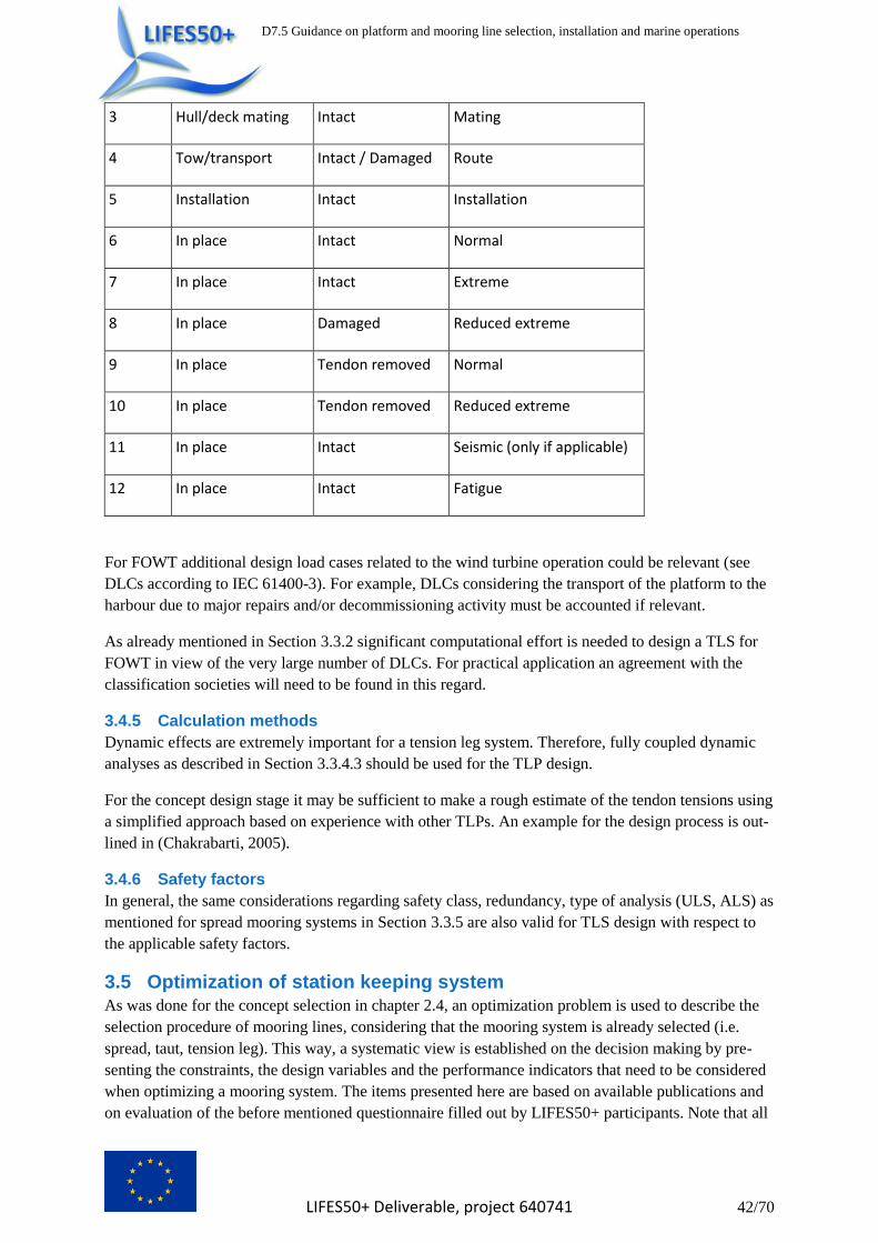
D7.5 Guidance on platform and mooring line selection, installation and marine operations
LIFES50+ Deliverable, project 640741 42/70
3 Hull/deck mating Intact Mating
4 Tow/transport Intact / Damaged Route
5 Installation Intact Installation
6 In place Intact Normal
7 In place Intact Extreme
8 In place Damaged Reduced extreme
9 In place Tendon removed Normal
10 In place Tendon removed Reduced extreme
11 In place Intact Seismic (only if applicable)
12 In place Intact Fatigue
For FOWT additional design load cases related to the wind turbine operation could be relevant (see
DLCs according to IEC 61400-3). For example, DLCs considering the transport of the platform to the
harbour due to major repairs and/or decommissioning activity must be accounted if relevant.
As already mentioned in Section 3.3.2 significant computational effort is needed to design a TLS for
FOWT in view of the very large number of DLCs. For practical application an agreement with the
classification societies will need to be found in this regard.
3.4.5 Calculation methods
Dynamic effects are extremely important for a tension leg system. Therefore, fully coupled dynamic
analyses as described in Section 3.3.4.3 should be used for the TLP design.
For the concept design stage it may be sufficient to make a rough estimate of the tendon tensions using
a simplified approach based on experience with other TLPs. An example for the design process is out-
lined in (Chakrabarti, 2005).
3.4.6 Safety factors
In general, the same considerations regarding safety class, redundancy, type of analysis (ULS, ALS) as
mentioned for spread mooring systems in Section 3.3.5 are also valid for TLS design with respect to
the applicable safety factors.
3.5 Optimization of station keeping system As was done for the concept selection in chapter 2.4, an optimization problem is used to describe the
selection procedure of mooring lines, considering that the mooring system is already selected (i.e.
spread, taut, tension leg). This way, a systematic view is established on the decision making by pre-
senting the constraints, the design variables and the performance indicators that need to be considered
when optimizing a mooring system. The items presented here are based on available publications and
on evaluation of the before mentioned questionnaire filled out by LIFES50+ participants. Note that all

D7.5 Guidance on platform and mooring line selection, installation and marine operations
LIFES50+ Deliverable, project 640741 43/70
items provided here are resulting from the authors’ evaluation of different sources of input and thus
may not represent the opinion of all LIFES50+ partners to the last detail. Also, the provided lists may
not be complete and could be subject to change in the future.
3.5.1 Constraints
In this section, relevant constraints in the selection of a mooring system are presented. They are classi-
fied according to different life cycle categories for better overview.
Table 15: Constraints in the selection of mooring lines
Life cycle
category
Constraint
D Numerical / design effort
D Site conditions
D Footprint
D VIV constraints
D Slackline events (more relevant for taut mooring lines)
D Connection limitations
D Corrosion allowance
D Anchor constraints
D Redundancy constraints
ML Logistical constraints
OM Required tension / system response
OM Excursion / displacements / offset limits
OM Load constraints / breaking strength (ULS, FLS, ALS)
DC Decommissioning constraints
D – Design
ML – Manufacturing & Logistics
IA – Installation & Assembly
OM – Operation & Maintenance
DC– Decommissioning
Numerical / design effort: The numerical / design effort required to design a mooring system within
guideline requirements might be excessively large, if the structure is too complex or too little infor-
mation exists on the behavior of the structure.
Site conditions: Site conditions may prohibit the use of certain mooring systems (e.g. due to soil con-
ditions, ice, wildlife, marine growth, seismic events, etc.).
In particular, the water depth may disqualify a certain mooring configuration altogether due to con-
straints from available installation procedures (e.g. excessive water depth). In addition, design condi-
tions may affect design compatibility for both moorings and structure (e.g. shallow waters; dynamic
cable demands that platform maximum drift allowed is 10-20% of water depth and this could lead to
unrealistic stiffness demands for too shallow waters. Also, water depth limits the maximum tension
producible by catenary mooring lines). Finally, the overall performance and FLS/ULS capacity of the
mooring system may be dependent on the water depth.
Footprint: The station keeping system needs to stay within the maximum footprint per installed unit.
VIV constraints: In case of high currents, vortex induced vibrations (VIV) require consideration as
they may pose constraints to the mooring line geometry.

D7.5 Guidance on platform and mooring line selection, installation and marine operations
LIFES50+ Deliverable, project 640741 44/70
Slackline events: The critical event of a taut mooring line being slack is to be avoided for all taut
mooring systems. Tension is recommended to always be positive (no slack tendons), even though
standards may allow exceptions. If designed for slack/snap phenomena, additional conservative load
amplification factors shall be included.
Anchor constraints: E.g. maximum uplift angle, allowance regarding load direction.
Redundancy constraints: Redundancy constraints may be part of the considered design. If not, re-
dundancy may be regarded as a design parameter (see below).
Logistical constraints: Logistical constraints may be present and limit the range of available systems
(e.g. supply chain limitations; only stud chains available).
Required tension / system response: If the platform type and the stability provided by the mooring
system is defined, a given tension is required from the mooring system for station keeping (e.g. sub-
structure was designed to be very soft, hence the mooring might require being stiff).
Excursion / displacements limits: The structural properties of the used dynamic cable or the allowa-
ble distance to other wind turbines may define limiting criteria for maximal displacements of the sys-
tem, which will be a restriction for the station keeping system. Also, the mooring connections may
have limitations with respect to maximum angles at the fairleads, which need to be considered.
Load constraints / breaking strength (ULS, FLS, ALS): Site-specific load conditions need to be
endured by the system. The applied guidelines can be used for definition of the relevant load cases.
Decommissioning constraints: Decommissioning requirements provided by local government must
be met (i.e. allowance for leaving behind anchors or mooring lines, using certain materials, etc.).
3.5.2 Design parameters
Each design parameter can be the base for a new optimization problem.
Table 16: Design parameters in the selection of mooring lines
Design parameters
Mooring concept
Anchors / Foundation
Material
Analysis method
Mooring configuration
Mooring line orientation
Redundancy
Sharing of mooring lines and anchors Breaking load
Mooring concept: In principle, three different mooring concepts can be considered of relevance: ten-
sion leg (vertical mooring lines), taut (taut mooring lines at an angle), and catenary (slack mooring
lines). Hybrid forms are also possible and have been used in the past. Each concept has different ad-
vantages and constraints, which need to be accounted for in the decision. Catenary mooring systems
are more reasonable with chains or studless chain due to lower bending loads compared to wires. It
should be highlighted that the basic mooring concept is typically part of the platform definition and
thus is likely to be selected designer-specific prior to the site-specific optimization of a substructure.

D7.5 Guidance on platform and mooring line selection, installation and marine operations
LIFES50+ Deliverable, project 640741 45/70
Anchors / Foundation: Different anchor types may be selected for spread and taut mooring lines. For
both platforms, the use of suction and pile anchors is possible. For spread mooring lines, or drag an-
chors may also be used, while for taut mooring lines drilled/grouted piles or gravity anchors can be an
option.
The foundation type for TLPs is selected under consideration of soil conditions, water depth, costs,
installation effort, etc.
For spread mooring lines, constraints towards the mooring line may be introduced regarding the al-
lowance of the uplift angle and the variation of load direction. Also for spread mooring lines, the an-
chor type may influence the redundancy of the mooring system (e.g. after line breakage in a 3-line
catenary mooring system with drag anchors the load direction on the remaining 2 anchors will signifi-
cantly change, probably causing failure of these anchors).
For TLP systems, a foundation may also be defined. Here, available options are:
- Foundation template (see, e.g. Gicon concept) anchored to the sea bed by piles. The tendons
are attached to the template or directly to the pipes.
- Non-piled gravity foundations to which the tendons are attached.
- Pile foundations (suction, driven or drilled) foundations to which the tendons are attached.
- Combination of the above types.
Material: The material selection depends on the specific conditions of the site, the technology used
and the available supply chain. It influences the breaking loads and the required load cases to be per-
formed for structural integrity checks. The optimization problem for choosing a material focusses on
the following options and related advantages:
- Steel
o Advantages: conventional design procedure, no need for tensioning during lifetime
o Options: wire, chain, pipes
Steel wire
Advantages: high fatigue reliability, light weight, compact
Options: spiral, multistrand
o Steel wire spiral advantages: high breaking strength, stiffness
Steel chain
Options: studded, studless
Advantages: low cost, only local bending effects
- Synthetic fibers (see also e.g. (Weller, et al., 2015), (Ridge, et al., 2010))
o Advantages: low cost, lightweight, compliant, reduced mooring footprint, good fa-
tigue performance, not susceptible to corrosion, lower installation tension
o Options: nylon, polyester
For a visual comparison of the different options available for steel-based mooring lines, Figure 13
shows the design S-N curves for different options.
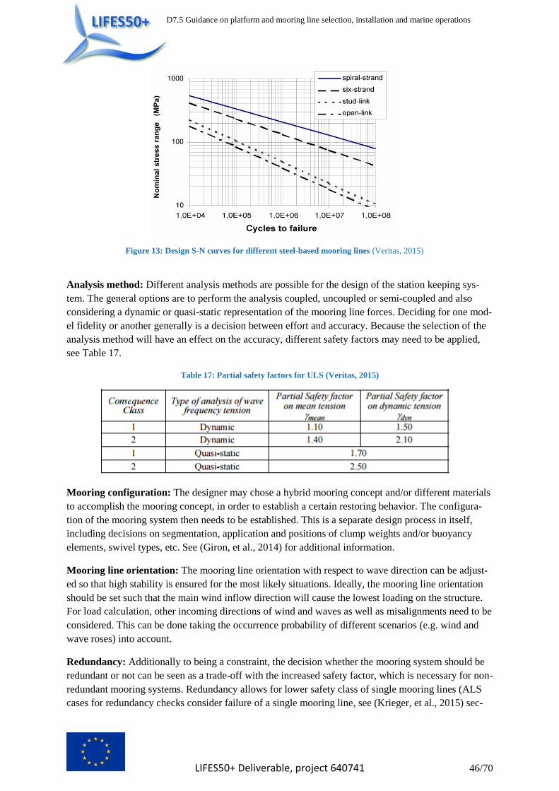
D7.5 Guidance on platform and mooring line selection, installation and marine operations
LIFES50+ Deliverable, project 640741 46/70
Figure 13: Design S-N curves for different steel-based mooring lines (Veritas, 2015)
Analysis method: Different analysis methods are possible for the design of the station keeping sys-
tem. The general options are to perform the analysis coupled, uncoupled or semi-coupled and also
considering a dynamic or quasi-static representation of the mooring line forces. Deciding for one mod-
el fidelity or another generally is a decision between effort and accuracy. Because the selection of the
analysis method will have an effect on the accuracy, different safety factors may need to be applied,
see Table 17.
Table 17: Partial safety factors for ULS (Veritas, 2015)
Mooring configuration: The designer may chose a hybrid mooring concept and/or different materials
to accomplish the mooring concept, in order to establish a certain restoring behavior. The configura-
tion of the mooring system then needs to be established. This is a separate design process in itself,
including decisions on segmentation, application and positions of clump weights and/or buoyancy
elements, swivel types, etc. See (Giron, et al., 2014) for additional information.
Mooring line orientation: The mooring line orientation with respect to wave direction can be adjust-
ed so that high stability is ensured for the most likely situations. Ideally, the mooring line orientation
should be set such that the main wind inflow direction will cause the lowest loading on the structure.
For load calculation, other incoming directions of wind and waves as well as misalignments need to be
considered. This can be done taking the occurrence probability of different scenarios (e.g. wind and
wave roses) into account.
Redundancy: Additionally to being a constraint, the decision whether the mooring system should be
redundant or not can be seen as a trade-off with the increased safety factor, which is necessary for non-
redundant mooring systems. Redundancy allows for lower safety class of single mooring lines (ALS
cases for redundancy checks consider failure of a single mooring line, see (Krieger, et al., 2015) sec-

D7.5 Guidance on platform and mooring line selection, installation and marine operations
LIFES50+ Deliverable, project 640741 47/70
tion 8.5.1. Analysis is for initial transient event and extreme condition of a failed line). It could be of
benefit to increase the number of lines in order to limit single line dimensions for larger wind turbines.
Sharing of mooring lines and anchors: While this becomes of increased importance only when fo-
cusing on wind farm design, the sharing of mooring lines and anchors from different platforms is a
design possibility that can be considered. Because anchors may scale better than mooring lines, for
larger units it may be of benefit to increase the number of lines and share anchors rather than increase
line dimensions.
Breaking load: The mooring lines may be designed for a specific breaking load and weak points may
be defined so load peaks do not damage the substructure.
3.5.3 Performance indicators
The indicators evaluating the performance of the mooring system originate from different stages of the
system lifetime and are listed categorized in Table 18 and described below.
Table 18: Performance indicators in the selection of mooring lines
Life cycle
category
Performance indicator
D Cost of components
ML Manufacturing and logistics efforts
IA Installation and assembly efforts
OM Restoring characteristic
OM O&M performance
DC Ease of decommissioning
D – Design
ML – Manufacturing & Logistics
IA – Installation & Assembly
OM – Operation & Maintenance
DC – Decommissioning
Cost of components: The cost of the components such as mooring lines, connectors and anchoring
system influences the overall cost of the mooring system. Catenary based mooring system concepts
(spar, barge, semi-submersible) tend to require less expensive anchoring systems than TLPs.. Other
auxiliary components may also have considerable costs.
Manufacturing and logistics efforts: As for the platform, a small effort in the manufacturing of the
mooring system is expected from modular components, flexibility with respect to the manufacturing
sites and a focus on simple and proven tools and methods. Manufacturing time may also be of im-
portance (e.g. production of chain vs. synthetic robes).
Installation and assembly efforts: When the mooring system is installed (i.e. anchor installation,
hook up, etc.), it must be tensioned to design pre-tension. If this can be done simple and fast with
small overall effort and with needing as little extra equipment on the FOWT (e.g. chain stoppers,
winches, etc.) as possible, it will be advantageous. Low masses and small dimensions of the mooring
lines and anchors will only support this. In addition, the number and variety of components should be
kept to a minimum to minimize assembly efforts.
Restoring characteristic: The restoring characteristic describes the mooring line behavior during
dynamic movements of the platform (see

D7.5 Guidance on platform and mooring line selection, installation and marine operations
LIFES50+ Deliverable, project 640741 48/70
Figure 4). A linear behavior around the equilibrium position ensures lower load uncertainty.
O&M performance: The O&M performance describes the overall effort of performing operation and
maintenance on the mooring system and the platform, and should be kept as low as possible (e.g. tem-
poral disconnection of mooring lines from platform, duration of inspections, etc.). As mentioned, fibre
ropes are likely to require tensioning during the lifetime, simple solutions to allow this are considered
of benefit.
Ease of decommissioning: Requirements with respect to vessels, winches, decoupling systems, etc.
will determine the cost of the decommissioning of the mooring lines.
3.6 Upscaling considerations and challenges for large wind turbines From LIFES50+ design experience, no particular effect of larger WTG on the mooring line design was
found. The same procedures and materials as were used for smaller WTGs could also be used for the
up-scaled systems. Some general concerns related to upscaling the mooring systems were collected as
part of the above mentioned questionnaire and are summarized next.
Although from a design perspective there is no general concrete limitation when increasing the size of
the mooring lines, there are some constraints in the overall system evaluation which will pose new
constraints which may limit the size of a turbine. For example, as the dynamic cable demands that
platform maximum drift allowed is 10-20% of water depth, the up-scaled platforms with higher loads
may require excessively stiff mooring systems for a given water depth. Additionally, with respect to
the allowed footprint, the up-scaled wind farm may require too much additional footprint in order to
mitigate overlap of the mooring system of different units. This could be avoided by increasing the
number of mooring lines. Then, the total seabed contact area increases rather than the mooring radius.
Also, it is to be expected that at some point increasing the mooring line size will be less beneficial than
increasing the number of mooring lines. For example, the transport of up-scaled chains/anchors may
require larger vessels that are much more expensive. Other items driving the increase of mooring line
number rather than size are installation methods, component availability and reliability. With respect
to the modelling, increasingly large elements in the mooring line will limit the use of simplified moor-
ing line models (hydro- and structural dynamics). As anchors may have better scalability than mooring
lines, different configurations (e.g. share of anchors) may become cost efficient solutions. An alterna-
tive to increasing the size of mooring lines and hence reaching the required mooring line stiffness is
the implementation of additional elements (e.g. clumps).
For an up-scaled anchoring system, the soil conditions could become inappropriate e.g. standard
commercial anchors could not be suitable when certain soil conditions are present. In such case, a
redesign of the anchors may be necessary.
3.7 Risk consideration in design of station keeping system The risk-based design approach has long been used in the aviation, and the nuclear industries, where
materialisation of a hazard can potentially lead to devastating consequences. However, more recently
the risk-based design approach has been also applied to other industries (e.g. ship design).
As given by (Papanikolaou, et al., 2009), there are two main reasons that make the risk-based design
approach attractive to ship design, but also to other industries. These are:
1. It allows novel designs to be realised that can be considered safe (i.e. considering safety as a
paramount design constraint from early design stages).
D7.5 Guidance on platform and mooring line selection, installation and marine operations
LIFES50+ Deliverable, project 640741 49/70
2. It allows existing designs to be optimised with respect to safety without compromising on per-
formance (i.e. considering safety as one of the constraints when optimising the initial designs,
which could have been designed without significant or any consideration of safety in the first
place).
It should be noted that the risk-based approach does not necessarily need to consider only safety. It can
be equally applied to other risk areas (e.g. environment, reputational damage, cost).
The risk-based design approach is equally applicable and attractive to floating wind turbines and its
elements (e.g. mooring lines) design, as all FOWTs can be seen as novel designs which have to main-
tain high performance, whilst not compromising on its other parameters or constraints (e.g. safety,
environment, cost).
The risk-based design of the station keeping system for a FOWT can help with the following:
To support a decision with regards to redundancy in the mooring system. This is particularly
important to those designs that achieve stability by means of mooring, such as TLPs. Howev-
er, this should not only be considered from the stability perspective, but also from a possible
damage to other systems elements (e.g. dynamic cable, wind turbine).
To compare different mooring designs/configurations (e.g. choice of material (steel versus
synthetic), number of interfaces, use of auxiliary equipment (e.g. lump mass, buoyancy units),
as well as choice of configuration (catenary versus semi-taut, versus taut).
To act as a tool for de-risking a chosen design (i.e. to be used as a risk management tool that
includes risk identification, risk analysis and evaluation, and risk mitigation).
Risk consideration with regards to the mooring lines should not only be associated with the technical
parameters (e.g. material, configuration), but should also cover all life cycle phases (i.e. design,
transport and installation, O&M, and decommissioning risks (e.g. wrongly approximated environmen-
tal loads, ease of inspection, marine growth).
Additionally, mooring system is just one part of the wider FOWT, hence it has to be considered not on
its own, but within the FOWT environment (e.g. how mooring line layout could potentially complicate
access for crew transfer vessels (CTVs), or how mooring lines could potentially damage dynamic ca-
ble) and within the wind farm environment (e.g. what are the other stakeholders that can be affected by
or can affect FOWT depending on the choice of the mooring system used (e.g. fisherman, environ-
mental consequence, MoD, air traffic). In other words, the consequence should not only be looked at
from the technology and financial perspective, but should also include, amongst other, H&S, and envi-
ronment.
3.8 LIFES50+ mooring design in WP5 In the Task 5.2 a conceptual mooring design for a 10MW semi-submersible FOWT (public LIFES50+
concrete semi-submersible as defined in D4.2) was performed. The conceptual design approach fol-
lowed an advanced quasi-static design approach, focusing on ULS conditions. The quasi-static calcu-
lation was performed by computing the offsets of the floater from the static and dynamic environmen-
tal forces and analysing the resulting mooring line design tensions and restoring forces. The floater
motion in the quasi-static computation was calculated with WAMIT, accounting for both 1st order
hydrodynamic forces and 2nd order hydrodynamic drift forces and viscous drag forces from current.
The mooring tensions were computed with a quasi-static catenary equation in-house software by Ram-
boll, which allows for multiple line materials and addition of clump weights and buoyancy elements
along the line. As governing standards, aligned with the design basis D7.2, the DNV-OS-J103 and

D7.5 Guidance on platform and mooring line selection, installation and marine operations
LIFES50+ Deliverable, project 640741 50/70
DNVGL-OS-E301 standards were used. As environmental conditions, the Gulf of Maine site was se-
lected as the average LIFES50+ site, and the ULS design conditions were selected along developed
50-year environmental contours by USTUTT. Since fatigue analysis usually requires rainflow count-
ing of time series, FLS was not considered. While in a detailed design, fatigue analysis is required
according to Offshore Standards, particularly DNVGL-OS-E301, fatigue analysis was neglected for
the design work in D5.2. From experience, at least for steel chain mooring systems, this assumptions
shall mostly hold true and lead to designs very close to the actual design when later considering FLS.
The ALS case was not calculated separately either. This approach is not specifically covered in DNV-
OS-J103, where only the approach for detailed mooring design is covered. Three different catenary
designs were developed: a classic 3-line steel chain mooring system, a 3-line hybrid polyester rope
catenary design with top and bottom steel chain, and a 6-line star-shaped configuration using steel
chain. While no detailed cost analysis was performed within the scope of this task, from the results
obtained the 6-line solution was considered as the most promising for further detailed design.
The lines of the first mooring system were steel chains. Steel chains are a common solution for compa-
rable cases: most current FOWT prototypes, as well as the world’s first pre-commercial floating wind
farm Hywind Scotland use steel catenary chain moorings. Also in research and development (R&D)
this system is the most commonly analysed, as e.g. demonstrated by the theoretical mooring design
approach in the South-Korean Jeju offshore area, developed by Kim, Choung and Jeon (Kim, et al.,
2014). A steel chain mooring thus allows comparability, as the mooring system for the public
LIFES50+ concrete semi-submersible from D4.2, developed by floater manufacturer Olav Olsen, also
uses a steel chain catenary mooring system.
The second mooring design was a hybrid solution, utilising synthetic materials as the main component
for the mooring lines. The catenary setup, however, does not allow a synthetic-only approach since
friction on the seabed and the connection to the floater at the top in the splash/trash zone could damage
synthetic mooring lines (Weller, et al., 2013), due to their higher sensitivity to wear and tear and abra-
sion. For such a solution a taut or semi-taut design would be required, which in O&G however is typi-
cally only applied at deep locations and thus has been disregarded for the current designs. Therefore
the mooring line consisted of three parts. The bottom part, which connects the mooring line to the
anchor, is a steel chain. A polyester line forms the main part of the mooring line. Polyester is chosen
as synthetic material based on good O&G experiences with the material. As an example, Weller et al.
state: “Nylon and polyester are the most commonly used rope materials for applications which require
moderately high strength and ductility.” (Weller, et al., 2013). Polyester is favoured by Weller et al.
over nylon due to better performances in regard to abrasion, creep and strength. To prevent contact
between the polyester line and the seabed, a buoyancy module can be utilised, and was considered as
an option during the iterative concept development. The top part of the mooring lines is again steel
chain, which prevents the synthetic part from being exposed in the splash zone. This hybrid design
with top and bottom steel chain and a shackled in polyester rope is a typical mooring system design
well known from O&G.
The third design was an innovative mooring system configuration, based on a proposal by Olav Olsen.
The lines are also steel chains, comparable to those which are used in the first design. In contrast to the
first design, however, the system contains six mooring lines. Both the number of the anchors and the
number of the connection points at the floating structure remain three. To each of the anchors two
lines are connected. These two lines are then linked to different connection points at the floater to form
a “star configuration”. Usage of this system promises the reduction of the loads on each single line
allowing usage of smaller chain diameters than in a comparable 3-line configuration, and also poten-
tially improves redundancy. The resulting total anchor load is not different between the 3 and 6-line

D7.5 Guidance on platform and mooring line selection, installation and marine operations
LIFES50+ Deliverable, project 640741 51/70
configurations (essentially the maximum substructure excursion and resulting overall force in the
worst direction remains the same and must be taken by the one anchor), except for the fact that one
anchor needs to connect to two lines, making the anchor-line connection more complex.
The conceptual mooring design process and the numerical analysis require the use of different pro-
grams and pre-calculations. They were combined by a MATLAB tool, which used them as input pa-
rameters. The interactions between the programmes, which are described here, are summarised in the
flow chart at the end of this chapter. The MATLAB tool, in which the actual quasi-static analysis was
implemented, is a Ramboll in-house software tool, which was specifically developed to create prelimi-
nary mooring designs with various mooring setups. It was modified to some extent in LIFES50+ to be
applicable particularly to more unconventional solutions such as the proposed 6-line system, where
two lines connect to one anchor. In the tool, the initial mooring design and the mooring system param-
eters are read in. Depending on further inputs and the quasi-static calculation, the resulting tensions
and overall system behaviour are computed. Based on these results, the initial mooring design is modi-
fied and reanalysed or set as final mooring design. This procedure is defined as primary iteration cycle
in the flow chart.
The quasi-static calculation is performed by computing displacements for the floater and establishing a
quasi-static equilibrium between tensions and restoring forces from the mooring system and static and
dynamic environmental forces. The equilibrium floater displacements are the main results of each
quasi-static simulation iteration. Once converged, the resulting tensions and system characteristics are
output. As inherent in the quasi-static approach, the offset is static, and does not account for dynamic
motions.
The programme differentiates between three different sources of environmental forces acting on the
FOWT and establishing its displacement. The first contribution is the static offset, which represents
the equilibrium position of the floater under steady environmental loads only. The linearized horizon-
tal restoring stiffness of the mooring system is determined at this point and forms the basis for the
calculation of the offsets due to first- and second-order hydrodynamic loads.
The second calculation is the determination of the system response at the largest offset due to first-
order motions. Hereafter, the oscillations due to second-order drift forces are calculated. The largest
offset and the corresponding system response are the characteristic results for the ULS case.
In summary, the considered environmental loads were:
- Steady wind and current loads (zero-order)
- Mean wave drift forces (second-order)
- Wave loads (first-order)
- Slowly-varying wave drift forces (second-order)
A missing analysis is the verification of the conceptual designs with dynamic simulations. For this
purpose, SIMA simulations were setup and ran in this task, but due to time constraints related to the
late publication of D4.2 and availability of substructure data, the calculations could not be included. In
a planned update of D5.2, this verification study for at least one of the three conceptual designs is in-
tended to be still included.
3.8.1 Key findings from LIFES50+ WP5 mooring design work
During the course of the conceptual designs in WP5, the following items were found which are of
relevance when designing a FOWT mooring system:

D7.5 Guidance on platform and mooring line selection, installation and marine operations
LIFES50+ Deliverable, project 640741 52/70
Design
Quasi-static design approaches offer robust and quick way to conceptually evaluate different
mooring design options.
Dynamic time-domain mooring design, accounting for all DLCs in DNV-OS-J103, is neces-
sary for the detailed design phase in order to verify initial conceptual designs.
Standards
Redundancy of three line systems cannot be determined unless detailed analysis are performed.
Safety factors for quasi-static design are mentioned in DNVGL-OS-E301, but according to
DNV-OS-J103 a final design must always be benchmarked against dynamic load simulations.
Thus the safety factors for conceptual design with quasi-static tools from DNVGL-OS-E301
may be either overly or non-conservative, making the conceptual level design completely
avoiding dynamic simulations rather challenging.
Tools
Both with dynamic and quasi-static approaches, second-order wave loads and drift forces on
the floater must be considered, as well as the current drag force.
The aerodynamic drag of the tower cannot be neglected.
Steel chain moorings
Simplest with regard to simulation and analysis. However, in detailed design modelling chal-
lenges with respect to chain soil interaction, and chain link wear and tear may become rele-
vant.
Mooring system behaviour is significantly affected by addition of clump weights. It increases
the restoring capacities of the system due to its high weight and also minimises the uplift angle
at the anchor point. Due to the impact of the clump weight the chain diameter can be reduced.
Dynamic response of clump weight was not validated.
Steel chain systems feature relatively high weight and associated higher line cost, when com-
pared to fibre ropes, but also steel wires.
Hybrid solutions with top and bottom chain and Polyester main line part
Low material costs and low weight.
Larger footprint.
Large floater offset.
Recycling of polyester undetermined.
Sensitivity to damages (abrasion, wear, tear) during installation and operation.
Periodical inspections might be required.
Manufacturing
Quality controlled suitable mooring line manufacturers are available near all LIFES50+ site
locations.
Current supply chain production capacities should be sufficient for mooring chain production
required for LIFES50+ wind farms.
Synthetic ropes are generally less expensive in manufacturing and procurement.
Installation
Pre-laying (of anchors and lines) is the less critical part of the mooring installation. However,
vessel requirements may be a challenge.
Hook-up (of lines to floating substructure and final tensioning) requires special equipment
such as winches, and also is on the critical project path – this makes this part of the installation
most critical to delays and cost.
Synthetic lines are more challenging to handle during installation than chain.

D7.5 Guidance on platform and mooring line selection, installation and marine operations
LIFES50+ Deliverable, project 640741 53/70
O&M
Proper structural integrity management is required for the lines and components, following
DNVGL guidelines with regular inspections.
Decommissioning
Generally better suited than fixed-bottom structures, with chain being more easily recyclable
than fibre ropes.
Environment
Nature reserves must be respected
The minimisation of the ecological impact must be ensured
The complete recovery of the offshore units including the mooring components is important.
Shipping and Military
Shipping routes and military considerations are important to take into account for a site specif-
ic design.
4 Installation and marine operations
4.1 Introduction
In current offshore projects involving floating structures, marine operations in general and installation
processes in particular constitute a large factor for cost reduction. Generally economies of scale result
in the fact, that the larger the wind farm, the larger the possible cost reduction per unit. The same
statement is likely true for usage of larger wind turbines reducing overall cost (however there may be a
limitation for this trend if WT sizes grow beyond e.g. 15MW – but this is still very unclear). Marine
operations of a floating wind project include:
Seabed preparation (in case it is needed)
Mooring system (pre-)installation / pre-lay
Anchor installation
Float out
Assembly of the substructure with the rotor nacelle assembly (RNA) and tower (quayside or at the
site)
Towing or transportation of the platform
Upending (relevant only for Spar buoys)
Hook-up / connection of the mooring system to the hull, if relevant also including pre-stretching,
proof loading, tensioning
Application of the dynamic cable to the electric system of the wind turbine
O&M operations
Decommissioning of the platform.
Since the design of floating wind platforms is under larger economic pressure than those applied in
offshore O&G, marine operations need to be optimized to make floating wind more feasible.
Marine operations are limited by the weather conditions including wave, current and wind. The as-
sembly of the substructure with the tower and RNA is particularly affected by the present environmen-
tal conditions. A significant challenge is to find a suitable weather window for the installation of a
floating offshore wind farm consisting of multiple units. There is also the possibility of connecting
several floating wind turbines in a coupled mooring system.

D7.5 Guidance on platform and mooring line selection, installation and marine operations
LIFES50+ Deliverable, project 640741 54/70
Floating turbines have a significant advantage compared to conventional bottom-fixed offshore wind
turbine that in case major corrective measures have been identified during O&M tasks, the floating
platform can relatively easily detached from the dynamic cable and the mooring system, and towed
back to a port for the repair.
The decommissioning of floating structures is less time-consuming as the platform only needs to be
detached from the mooring system and dynamic cable and towed back to the port where it can be
completely dismantled. In the case of Spars and TLPs, these may require tower and RNA removal
before the towing back to the port, due to the water depth limitations and limited hydrostatic stability.
Special attention needs to be placed on removing the tendons from a TLP.
4.2 Common installation procedures for floating structures This chapter is meant to give an overview of existing installation procedures applied in the floating
wind business and related industries. The installation procedures are split into those applied for catena-
ry, semi-taut and taut mooring systems and those applied for tension leg systems.
The mooring system is usually pre-installed and the attachment of the lines to the substructure is done
as soon as the platform has been towed to the site. The mooring line is usually pre-installed and the
connection to the platform usually takes 9-12 hours (this is an indicative assumption and may vary
significantly depending on the design). In the Fukushima FORWARD project, the installation of the
mooring system for the electrical substation took about 4 months (Fukushima Offshore Wind
Consortium).
The inter-array cable is usually also pre-installed. The longest part of the inter-array cables are typical-
ly buried, if soil conditions allow, as done for bottom-fixed offshore wind turbines. The cables are
buried to reduce fatigue loads (limits motions), to reduce risk of damage from other subsea equipment
(e.g. anchors dropped on the cable, fishing nets catching on the cable, electromagnetic radiation,
sharks biting cables) and to reduce the risk to other subsea equipment or creatures living in the sea
(entanglement of fish or equipment). The last part of the inter-array cables (the so called dynamic ca-
ble) close to the turbine is kept to most extent above the seabed by buoyancy modules to avoid scrap-
ing of the cable with the seabed. The buoyancy units are also used to introduce a slack in the system
to account for FOWT motion. This means the dynamic cable is hanging loose to be able to adapt to
large horizontal offsets of the platform under maximum thrust force or harsh environmental conditions
or at the event of line failure. There is usually a touch down point anchor, as well as some protection,
like stiffeners, at the transition from the static to dynamic part. Similar to bottom- fixed wind turbines,
floating turbines are normally equipped with a J-tube which requires a cable pull-in procedure during
the installation process although other alternatives are also feasible (e.g. a direct connection at the
bottom section of the floating structure).
4.2.1 Installation of anchors
4.2.1.1 Drag Anchors
Drag anchors are usually applied as the anchoring point of catenary mooring systems as they do not
allow a vertical lifting force. For the installation of drag anchors, in general, an Anchor Handling Ves-
sel (AHV) is chartered. The anchors, and, depending on the mooring system design, the anchor chains
and/or the (synthetic) ropes are lifted by an onshore crane onto the AHV deck area where it is fastened
for the sea transport. At the site, the position of the vessel and the drag anchor needs to be tracked
continuously. The anchor is connected to the anchor chain and the subsequent mooring line and low-
ered from the stern utilizing the winch mounted on the AHV deck. To ensure that the drag anchor will

D7.5 Guidance on platform and mooring line selection, installation and marine operations
LIFES50+ Deliverable, project 640741 55/70
reach the seabed in the right orientation, a supporting second line may be used which is later discon-
nected from the anchor by an ROV. As soon as the anchor touches the seabed, the vessel moves for-
ward. The vessel’s thrust and the angle between the fluke and shank makes the anchor embed into the
soil. If this angle is determined incorrectly, the anchor might lose its holding power. The tension in the
line is monitored and the line is paid out completely. The upper end of the mooring line is connected
to buoyancy modules to ensure easy pick-up for the platform installation and to avoid clashing of the
line with the seabed.
4.2.1.2 Plate Anchors
In case a larger holding capacity than those provided by drag anchors is needed, plate anchors might
be a solution. Larger holding capacity is required in case a taut or semi-taut mooring system is chosen.
Plate anchors are pushed into the soil and rotated so that the plate is directed orthogonally towards the
tension force direction. Plate anchors can be pushed into the soil by suction piles or drilled piles. The
plate anchor is mounted to the lower end of the pile by a tension force. The plate is directed orthogo-
nally to the seabed to reduce the friction force. When reaching the design penetration depth, the anchor
is released from the pile. The pile is pulled upwards and stored on board the support vessel for the next
anchor to be installed. The plate anchor is connected to transition lines made of steel which are kept
above the seabed. Those transition lines are later connected to the mooring chain and mooring line
utilizing an ROV. The upper end of the line is kept at sea level by a buoyancy module. When the
mooring lines are connected to the platform, the lines are tautened. By applying the tension force, the
plate anchor rotates into a position where the plate is directed orthogonally towards the mooring line
and the tension force. The pressure of the soil wedge in load direction is keeping the plate anchor in
place. Figure 14 visually illustrates the procedure.
Figure 14: Plate anchor installation (www.intermoor.com)
4.2.1.3 Suction Anchors
Suction anchors are piles that are pulled into the soil by applying a negative pressure in the inside of
the pile. The anchors are stored on the installation vessel which needs to be equipped with a high ca-
pacity crane and a (subsea or at the side of the vessel) pile guide (see Figure 15) or an A-frame crane
at the stern of the vessel and a deck transporting system to move the piles on the deck. The suction
anchors are lifted and lowered down to a pre-installed template which might be required under specific
soil conditions to ensure the correct position of the anchor and their verticality. The suction anchor
penetrates the upper soil level by its own weight. An underwater pump (typically pre-installed on the
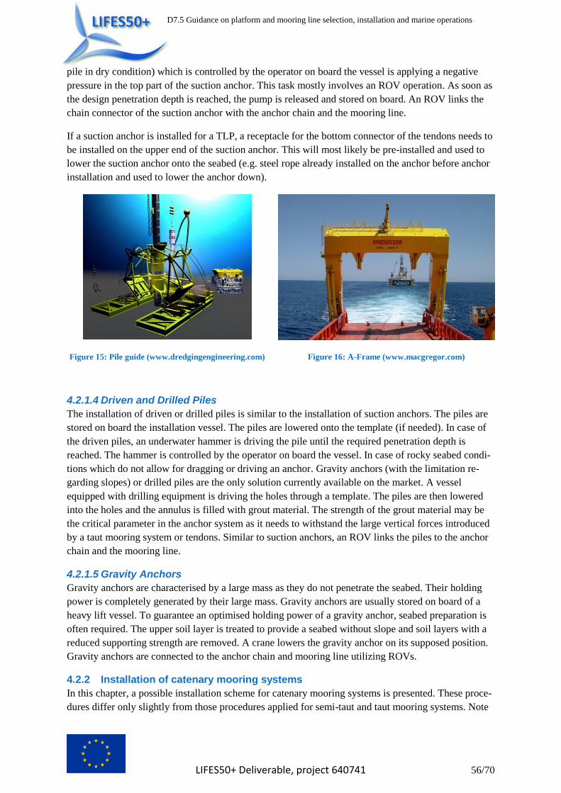
D7.5 Guidance on platform and mooring line selection, installation and marine operations
LIFES50+ Deliverable, project 640741 56/70
pile in dry condition) which is controlled by the operator on board the vessel is applying a negative
pressure in the top part of the suction anchor. This task mostly involves an ROV operation. As soon as
the design penetration depth is reached, the pump is released and stored on board. An ROV links the
chain connector of the suction anchor with the anchor chain and the mooring line.
If a suction anchor is installed for a TLP, a receptacle for the bottom connector of the tendons needs to
be installed on the upper end of the suction anchor. This will most likely be pre-installed and used to
lower the suction anchor onto the seabed (e.g. steel rope already installed on the anchor before anchor
installation and used to lower the anchor down).
Figure 15: Pile guide (www.dredgingengineering.com) Figure 16: A-Frame (www.macgregor.com)
4.2.1.4 Driven and Drilled Piles
The installation of driven or drilled piles is similar to the installation of suction anchors. The piles are
stored on board the installation vessel. The piles are lowered onto the template (if needed). In case of
the driven piles, an underwater hammer is driving the pile until the required penetration depth is
reached. The hammer is controlled by the operator on board the vessel. In case of rocky seabed condi-
tions which do not allow for dragging or driving an anchor. Gravity anchors (with the limitation re-
garding slopes) or drilled piles are the only solution currently available on the market. A vessel
equipped with drilling equipment is driving the holes through a template. The piles are then lowered
into the holes and the annulus is filled with grout material. The strength of the grout material may be
the critical parameter in the anchor system as it needs to withstand the large vertical forces introduced
by a taut mooring system or tendons. Similar to suction anchors, an ROV links the piles to the anchor
chain and the mooring line.
4.2.1.5 Gravity Anchors
Gravity anchors are characterised by a large mass as they do not penetrate the seabed. Their holding
power is completely generated by their large mass. Gravity anchors are usually stored on board of a
heavy lift vessel. To guarantee an optimised holding power of a gravity anchor, seabed preparation is
often required. The upper soil layer is treated to provide a seabed without slope and soil layers with a
reduced supporting strength are removed. A crane lowers the gravity anchor on its supposed position.
Gravity anchors are connected to the anchor chain and mooring line utilizing ROVs.
4.2.2 Installation of catenary mooring systems
In this chapter, a possible installation scheme for catenary mooring systems is presented. These proce-
dures differ only slightly from those procedures applied for semi-taut and taut mooring systems. Note

D7.5 Guidance on platform and mooring line selection, installation and marine operations
LIFES50+ Deliverable, project 640741 57/70
that the installation procedure described below is only one of many possible alternatives. The installa-
tion sequence applied for a specific project will be dependent on the companies involved, the envi-
ronmental conditions at the site, the mooring line material, the water depth, the anchor types, the type
of substructure and the soil conditions.
Assuming that the anchors and the mooring lines have been pre-installed which is common industry
standard, the upper end of the mooring line is connected to a buoyancy module. This buoyancy ele-
ment is marked in a bright colour to make it easier to find in case of bad visibility.
A previously mentioned in chapter 4.1, the substructures are floated out, the assembly of the sub-
structure with the rotor nacelle assembly (RNA) and tower (quayside or at the site) are performed
and the assembled system is transported to the installation site.
In case a Spar platform is used, the upending process is initiated. The ballast water tanks are flooded
with sea water and additional high density ballast material is filled into the lower ballast tanks if in-
tended in the design.
Assuming a chain stopper is installed on each mooring line and that no mooring line section is pre-
installed on the substructure, an AHV (typically already chartered for the platform installation and
probably used as tugs for towing the platform to position),picks up the upper end of the mooring line.
The upper end is connected to a chain stopper and the buoyancy modules are removed and stored on
deck of the vessel. The AHV approaches the FOWT structure close to one fairlead. A messenger line
which is connected to the platform chain is shot over from the FOWT and the platform chain stopper
is activated. The messenger line is connected to the deck winch of the AHV and the platform chain
stopper is deactivated. The AHV winch starts hauling in the messenger line and the platform chain. A
specified length of the platform chain is stored on the AHV deck. The platform chain stopper is acti-
vated. The platform chain is released from the messenger line and connected to the (synthetic) moor-
ing line. The platform chain stopper is deactivated and the platform winch starts hauling in the plat-
form chain until a pre-defined line tension is reached. The chain stopper is once again activated. This
process is repeated until all mooring lines are connected to the FOWT. The tensions of all mooring
lines are monitored and the position of platform is checked and corrected if necessary. In case the
winching equipment is temporary, the winching equipment and power supply is dismantled and in-
stalled on the next platform. In case no chain stoppers are used, a modified procedure is applied, e.g.
using a winch to generate the required pre-tension in the line, then using a shackle to connect the line
and disconnecting the excess part of the chain.
After installing the mooring system, the dynamic inter-array cable needs to be handed over to the
floater. A crane vessel picks up the pre-laid cable and hands it over to the platform where a messenger
line is guided through the J-tube and connected to the cable end. The messenger line can also be pre-
installed. The cable is pulled through the J-tube and connected to the electrical system of the turbine. If
the commissioning has not been done at the quay, it needs to be done at this point.
During the installation process, a careful monitoring of the line tensions is required by offshore stand-
ards. There are different ways to determine the line tension. One method is to install load cells at the
winches or chain jacks on the platform. Another method is to monitor the departure angle of the moor-
ing lines. The latter is recommended by (Bhattacharjee, 2017) for shallower water depths. When moni-
toring and assessing the line tensions during installation, the tidal variations need to be taken into ac-
count.

D7.5 Guidance on platform and mooring line selection, installation and marine operations
LIFES50+ Deliverable, project 640741 58/70
In case a taut or semi-taut mooring system is used, the installation sequence is similar to the one ap-
plied for catenary mooring systems. The anchor and mooring lines are pre-installed and the upper ends
of the synthetic lines are kept afloat by buoyancy modules. After the pick-up of the line by an AHV
and the taking over by the platform, the mooring lines are tautened and the plate anchor is rotated into
its final position (only in case a plate anchor has been selected). As indicated above, the synthetic lines
should have been pre-stretched by two AHVs pulling the line in opposite direction. An inelastic stretch
called creep is applied to the lines. If creep is not applied in advance, it might occur under harsh envi-
ronmental conditions during operation, changing the restoring stiffness (ABSG CONSULTING INC.,
2015), hence reducing the safety and reliability of the floating wind platform.
4.2.3 Differences in installation processes for Spars, semi-submersibles and TLPs
There are some major differences in the installation processes of the common offshore floating plat-
forms. Because the installation sequence of Tension Leg Platforms (TLPs) differs significantly, it is
presented in a separate section. TLPs and semi-Submersibles are usually fabricated upright, flooded
with ballast water, attached with buoyancy elements (if required for sufficient hydrostatic stability)
and towed to site by tugs (wet tow). There is also the opportunity to transport the platforms with a
semi-submersible vessel to the site (dry tow). Dry tow has the advantage that – depending on the size
of the cargo ship – multiple substructures may be carried at once as well as better towing conditions
reached (e.g. higher towing speeds, wider weather windows…). However for a specific design and
site, only a cost-benefit analysis will show the most cost-effective means of transportation.
Spar platforms are characterised by a large draft. Hence, they cannot be fabricated and towed upright.
During tow-out, buoyancy elements may also be attached to the hull to provide additional hydrostatic
stability. At the site, the spar is upended by means of the ballast tanks being flooded. In some cases,
the ballast tanks at the lower end of the spar will be ballasted with additional high density material to
lower the overall centre of mass and improve stability. Once the spar platform is upended and is bal-
lasted, it is hydrostatically stable, even without the mooring system. Spars require the installation of
the wind turbine and the tower at the site or in an alternative site with sufficient water depth (as done
with a deep near shore area for the Hywind Scotland project). For this process, crane vessels are need-
ed.
In general, semi-submersible FOWTs will have large overall dimensions, which means that fabrication
is only possible at limited number of shipyards. Spars in comparison are much longer structures, how-
ever much more slender, which may be an advantage for common shipyards, mainly designed for
shipbuilding (ships are also rather slender, long structures). Before assembly and tow-out, the semi-
submersible is ballasted and achieves a hydrostatic stable position. The assembly of the substructure
with the tower and wind turbine can be done utilizing the onshore cranes. Semi-submersibles have a
larger draft than TLPs or barges and thus they require a larger harbour water depth. Semi-submersibles
can be towed by tugs to the site where they are connected to the mooring system and the dynamic ca-
ble.
In general, an optimised manufacturing process requires the adaption of the yard layout towards a line
production with time and cost efficient structure handling processes.
4.2.4 Installation of Tension Leg Platforms (TLPs)
Tension leg mooring systems are installed in a different manner as described in the section above.
TLPs usually have a significantly lower steel and total weight and have smaller dimensions than the
other platform types. The fabrication of TLPs will be possible at many shipyards. TLPs are typically
not hydrostatically stable without the tendon system installed/attached. Hence, they need to be con-

D7.5 Guidance on platform and mooring line selection, installation and marine operations
LIFES50+ Deliverable, project 640741 59/70
nected to buoyancy elements that provide sufficient stability. Dry towing of the structure is also a fea-
sible option due to the dimensional optimization and light platform weight. Another approach has been
introduced by Glosten. For the TLP design named Pelastar, a U-type barge has been designed for in-
stallation. The TLP is ‘clamped’ under its arms and towed to the site, see Figure 17. In this case, the
turbine and tower can be attached to the substructure by onshore cranes.
Figure 17: Installation barge for the Pelastar Tension leg Platform (Pelastar)
A similar approach using a U-shaped semi-submersible barge has been introduced by Iberdrola for its
TLPWIND® concept, see Figure 18. The combined system of TLP and semi-submersible barge is
hydrostatically stable at any stage/draught of the transport and installation operation.

D7.5 Guidance on platform and mooring line selection, installation and marine operations
LIFES50+ Deliverable, project 640741 60/70
Figure 18: Semi-submersible barge TLP transport concept (figure by Iberdrola)
The GICON SOF TLP will be manufactured in a dry-dock and the wind turbine will be installed at the
quay. The structure will be towed to the site by four tugs. During the towing, the structure will be in a
hydrostatically stable position as a heavy gravity anchor will be attached to the bottom of the substruc-
ture and the four lateral columns will contribute sufficient flotation inertia. At the site, the anchor will
be lowered to the seabed utilizing the synthetic tendons already attached to the anchor and the hull.
Ballast tanks in the TLP columns will be filled to provide hydrostatic stability during the installation
process. As soon as the anchor will be placed on the seabed, the ballast tanks will be emptied and the
tendons will become tensioned (GICON-SOF).
In offshore O&G, there are two main principles of tendon installation sequence – vertical and lateral
installation (see the next sections). The floating wind installation sequence varies significantly from
these, as has been indicated by the two examples of FOWT TLPs shown above.
4.2.4.1 Vertical installation in O&G
To reduce the installation time with the platform being at site, the anchors can be pre-installed. To
ensure verticality of the tendons, a seabed template might be necessary for their installation. The TLP
is towed to its final site. Since floating TLPs usually have a reduced hydrostatic stability, they are bal-
lasted and kept stable by tugs or being transported on top of a barge/vessel. The tendons are stored,
lifted and lowered from an installation vessel through the porches at the TLP hull. Depending on the
water depth at the site, a connection process of the tendon parts might be required. This is because the
available individual lengths of tubular steel tendon sections is limited and multiple tendon sections
may need to be used to achieve the required overall tendon length. The lower end with the bottom
connector is placed into the receptacle of the suction anchor and the top connector is above the porch
at the TLP hull. As soon as all tendons are installed, the TLP de-ballasts and applies tension force to
the tendons and hence reaches a stable floating position.
In a second installation sequence of the vertical installation, the tendons are completely pre-installed
from the installation vessel. In O&G industry, the tendons are made of steel pipes which require an
offshore welding process at the installation vessel, since steel pipes cannot be spooled. The lower end
of the tendons is equipped with the bottom connector and the upper tendon part is equipped with the
top connector. The tendons are brought under tension by temporary tendon buoyancy modules
(TBMs). Distance holding wires are installed in some cases which protect the tendons from clashing
against each other. The TLP is towed to its final position and positioned above the tendons. A guide

D7.5 Guidance on platform and mooring line selection, installation and marine operations
LIFES50+ Deliverable, project 640741 61/70
element for the top connector is lowered by a platform winch though a porch at the hull and connected
to the top connector at the tendon upper end. As soon as all tendons are connected, the TLP is ballasts
further until the tendon top connectors are above the porches. The final top connectors are installed
and a fixed vertical connection is applied. The TLP de-ballasts to apply a tension force to the tendons
and hence reaches a stable floating position. Finally, the TBMs are removed.
4.2.4.2 Lateral installation
Another possible TLP installation approach is a lateral installation. The anchors and tendons are pre-
installed from an installation vessel as described for the second vertical installation sequence. The TLP
arrives to site by dry or wet tow and is kept stable by tugs. The TLP is ballasted and the tendons are
inserted into the porches on the hull laterally. As soon as all top connectors have been inserted into the
porches, the TLP starts to de-ballast and apply the tension force in the tendons required for a stable
floating position. Finally, the TBMs are removed from the tendons.
The main difference between offshore O&G and floating wind TLP concepts is that the type of ten-
dons use is completely different. Whereas in O&G the tendons are made of steel pipes, for floating
wind TLPs synthetic lines or steel ropes are usually used. In floating wind industry, there are several
concepts based on the TLP principle, some of which use inclined tendons.
4.2.5 Logistical constraints
There exist some logistical constraints for FOWT installation that need to be considered. These are
listed below:
- The size of the fabrication dry dock or construction area must provide enough space to ac-
commodate the selected platform (or several platforms if a line production of multiple sub-
structures is selected) OR the platform needs to be designed according to the dimensions of
the chosen yard. Only a few dry docks worldwide would be able to accommodate the large
dimensions of substructures for 10 MW wind turbines.
- The transport routes towards the fabrication yard should not limit the supplied part masses and
dimensions significantly.
- The storage and construction area needs to have a sufficient bearing capacity.
- The harbour water depth needs to be sufficient if the substructure is designed to be towed out
on a large draft taking into account the tidal variations. Otherwise, cost intensive transport al-
ternatives (semi-submersible barges or towing on a reduced draft with additional stabilization
pontoons) need to be evaluated.
- The canal width needs to be significantly larger than the substructure dimensions.
- If the turbine and tower are designed to be attached to the substructure using the onshore
cranes, the overall height must be lower than the lower bound of any bridge between yard and
installation site.
- The onshore (gantry) cranes should have sufficient height and capacity to lift the tower and
RNA onto the substructure. The requirements for the cranes increase with larger turbine rat-
ings as the RNA height and total masses increase. Currently onshore gantry cranes do not have
the capacities required for the reference LIFES50+ 10MW WT, thus large and expensive mo-
bile cranes (temporarily constructed and operated at the installation port) must be used cur-
rently.
- The yard should provide enough (sheltered) storage space for the turbine towers, blades and
nacelles as well as for the mooring system components.
- The quay should provide enough space for multiple substructures if a line fabrication is select-
ed.

D7.5 Guidance on platform and mooring line selection, installation and marine operations
LIFES50+ Deliverable, project 640741 62/70
- Depending on the main floater material (steel or concrete), appropriate yard infrastructure
needs to be available.
- Concrete floaters are restricted regarding the environmental conditions during fabrication.
Here particularly moisture (rain, snow) and temperature (mainly cold) could affect the pouring
and curing process.
- If a line production is selected, sufficient means of transporting components within the port
need to be available.
- The distance between the port and the wind farm has a direct impact on the length of the
weather window for platform installation. Weather is often not predictable for the complete
time of transport.
It is likely that the facilities and the infrastructure of the fabrication port will require modification for a
specific floating wind project. It needs to be analysed whether the infrastructure of the installation port
would be able to accommodate a floater in case of repair.
4.3 Equipment
4.3.1 Vessels
Marine operations in floating wind industry require use of different types of supporting vessels. This
includes, among others, vessels for towing, lifting (and upending), anchor and mooring handling, posi-
tioning of the platform, cable laying and for crew transfer in the operation phase. As indicated above,
unique vessels, such as the transport barge for the Pelastar TLP concept, may be designed to guarantee
an optimal solution for the special requirements of floating offshore wind.
In general, sea going tugs are utilized for the harbour and sea towing, as described by the FLOATGEN
partners for its benchmark FOWT (FLOATGEN) and by Mitsubishi Heavy Industries for the Fuku-
shima Shimpuu (Komatsu, et al., 2016). These tugs should have a dynamic positioning (DP) system to
position the floater exactly. For the attachment of the mooring lines to the floater, one or more AHVs
are generally needed, since common tugs are not able to execute this type of work.
The sea towing is in general limited by the sea states present on the route. The maximum significant
wave height that can be survived by the towed structure is dependent on the type of substructure, its
dimensions, the angle of attack of the sea state and the type of tugs used. Since AHVs, which are larg-
er than sea tugs, can operate under harsh environmental conditions, it might be preferable, for some
locations, to charter the more expensive but more reliable AHVs instead of sea going tugs.
It might also be necessary to utilize multi-purpose support vessels or platform supply vessels taking
advantage of their additional deck space and crane capacities.
For O&M processes and minor repairs, the structure can be accessed by common CTVs since the sub-
structures are equipped with a boat landing structure.
The vessels required for FOWT installation constitute a large proportion of the overall project cost.
Prices and availabilities vary strongly depending on season, geographical location and market situa-
tion. The vessels needed for installation of one or multiple FOWTs should be determined carefully for
an economically optimised installation process. The larger the distance between the installation base
and the site, the more tugs or AHVs are needed to avoid a delay of a multiple turbine project.

D7.5 Guidance on platform and mooring line selection, installation and marine operations
LIFES50+ Deliverable, project 640741 63/70
It can be concluded that marine operations for floating structures require less sophisticated and less
expensive offshore vessels than marine operations for bottom-fixed offshore wind turbines, if the as-
sembly of wind turbine and substructure has been carried out at the quay.
4.3.2 ROV, AUV
For the installation of the anchors and for inspection purposes during the operation lifetime, the use of
ROVs or autonomous underwater vehicles (AUVs) or divers (not recommended) is required. The
ROVs can monitor the position and orientation of drag anchors, connect the bottom connector with the
suction anchor of the tension leg system and connect a mooring chain to a suction anchor or pile.
ROVs are also used to inspect the condition of the mooring lines in defined periodic intervals. ROVs
can also follow subsea equipment down to the seabed as it is lowered from the installation vessel. This
significantly reduces the reaction time of the operator in case a process was not executed as designed.
4.3.3 Mooring equipment
The mooring equipment may provide a large contribution towards the total mass of the FOWT de-
pending on the specific mooring and platform typologies... It consists of various elements of different
sizes. It is likely that those elements are manufactured by several suppliers at different locations. The
mooring elements are transported to the storage area at the installation port either on road or on a riv-
er/the sea. The port which serves as base for installation does not necessarily need to be the port of
fabrication of the substructure. The mooring line which is most likely to be made of a synthetic mate-
rial is typically transported and stored on reels. Synthetic lines can be stored in reels with a smaller
diameter than steel wire lines (Chakrabarti, 2005). Other mooring elements that are provided by sup-
pliers may be one or more of the following: clump weights, anchor chain weights, buoyancy elements,
shackles or other chain connectors, rope socket, top, intermediate and bottom connectors for tendon
systems and monitoring devices. The reel diameter needs to be chosen with respect to transportation
limitations and a suitable bending radius. There should be heavy lift systems available at the port. If
the mooring equipment is transported by a heavy lift vessel, the vessel cranes may be used for offload-
ing. Nevertheless, for a loading on deck of the multi service vessel (MSV), onshore crane capacities
are needed. Fastening equipment for the sea transport should be provided by the suppliers. The moor-
ing system is dependent on the turbine rating and on the installation site (water depth, soil conditions,
metocean conditions, etc.). Larger turbine thrust will increase the loads in the mooring system, but the
environmental conditions are relatively of a higher impact (at least when considering moderate differ-
ences in WT ratings, e.g. 8-10MW range). Smaller turbines in a harsh environment likely require
stronger mooring elements than a large turbine at a calm location.
4.3.4 Tower and wind turbine
Assuming 10MW+ ratings, the tower and RNA are usually transported by the respective manufacturer
on a river or by the sea. Since the blades and the tower are large elements, the wind turbine requires
large storage areas at the yard. The storage area required will increase for turbines with a larger power
rating, for a wind farm with multiple turbines and if the storage time from supply to system assembly
is increased. The tower and RNA will either be installed at the quay utilizing large capacity onshore
cranes or be transferred to a barge for a later assembly offshore. If a fabrication yard of the substruc-
ture and an installation port which are not the same, the assembly of substructure and wind turbine can
be done at either of the ports assuming that there is sufficient crane capacity at both ports.

D7.5 Guidance on platform and mooring line selection, installation and marine operations
LIFES50+ Deliverable, project 640741 64/70
4.4 Assembly
4.4.1 On site
It is common practise to pre-install the anchors and mooring lines of catenary mooring systems. Ten-
don systems may also be pre-installed. When arriving at the site, the floating wind turbine can be di-
rectly attached to the mooring lines or tendons. Another method is to execute the mooring system in-
stallation at the site as soon as the platform arrives. The first procedure has large advantages regarding
the weather window required for platform installation.
An offshore assembly of the wind turbine and the platform is for some types of substructures not re-
quired and it is in general not favoured by designers and operators. Bottom-fixed structures are assem-
bled at the site using jack-up vessels. It is rather unlikely that towers and RNAs of floating offshore
wind turbines will be installed at site using jack-up vessels due to large water depths and larger tower
and RNA sizes. Hence, for the assembly at site crane vessels would be required. Those vessels are
characterised by large rental costs and a very restricted availability on the market.
Thus, an assembly at site would in general increase installation costs (larger and/or more installation
vessels required) and increase the offshore installation time frame.
4.5 At port A full assembly at the port is technically not possible, since the mooring system and the electrical ca-
bles will be attached to the platform at site. Nevertheless, designers, operators and manufacturers
strive to assemble as many FOWT elements as possible at the port and in sheltered areas (Spar). If the
port conditions (e.g. size of the production facility, crane capacities, harbour water depth, bridge
heights) allow for an almost complete assembly of the platform and the wind turbine, this is done. The
substructure of the 7MW V-shaped semi-submersible Shimpuu in the Fukushima FORWARD project
has been manufactured in Nagasaki, but the assembly of the platform with the wind turbine has been
performed at the port of Onahama close to the installation site (Komatsu, et al., 2016). It is likely that
due to economic reasons and hydrostatic stability, the port of production of the substructure and the
port of assembly are not the same.
A big advantage of the full assembly at port is that the commissioning of the wind turbines can take
place in protected areas. The duration of this process could exceed several days under offshore condi-
tions.
For the assembly of the substructure with the tower and RNA, relatively cost and time efficient on-
shore harbour (gantry) cranes of the yards may be utilized, if the size of the WT and tower allows. As
commented earlier, for the LIFES50+ considered 10MW class, currently no suitable gantry cranes are
available at ports and yards and special, mobile cranes or heavy lift vessels are required.
4.6 Risk consideration for installation and marine operations As explained in Section 3.7, risk should not only be considered for the design phase of a FOWT, but
should also be considered for all other lifecycle phases.
This section considers risk during installation and marine operations of FOWTs. Several risks manifest
during the installation and marine operation of FOWTs. Some of these risks are industry agnostic such
as the generic risks of working with electrical and mechanical equipment, manual lifting, etc., whilst
D7.5 Guidance on platform and mooring line selection, installation and marine operations
LIFES50+ Deliverable, project 640741 65/70
some are similar to risks inherent in other offshore industries such as oil and gas and bottom-fixed
offshore wind. Examples are:
Health and safety risks to offshore personnel resulting from events such as diving operations,
vessel capsize, collapse of structure, etc.
Health and safety and environmental risks resulting from steel corrosion leading to compro-
mised structural integrity.
Weather risks linked to metocean conditions leading to health and safety risks to personnel,
vessels and the environment.
Navigation and aviation risks leading to health and safety risks to personnel, vessels, and the
environment.
Environmental risks resulting from the pollution of the environment from multiple sources
such as vessels, working materials like paint, etc.
Yet apart from the industry agnostic risks and risks transferred from bottom-fixed offshore wind, there
are specific risks inherent to installation and marine operation of FOWTs. Examples of these risks are:
Health and safety risks arising from loss of mooring line during installation leading to instabil-
ity of the structure or even collapse of the structure.
Health and safety risks arising from incorrect ballasting of the substructure leading to instabil-
ity of the structure or even collapse of the structure.
Health and safety risks arising from relative motion between turbine and vessel during crew
transfer.
Increased weather window risks due to relatively low towing speeds for FOWTs.
Health and safety risks due to higher need for divers during installation operations.
Health and safety risks resulting from damage to dynamic cables during marine operations.
Also, apart from the health and safety risks to personnel mentioned above, there are also other risks
associated with FOWTs during installation and marine operation such as project cost increases, envi-
ronmental pollution, reputational damage to the industry and companies, etc.
Due to the nature of FOWTs (multiple processes are repeated in different lifecycle phases), various
hazards are applicable (but at varying probabilities and consequences) to both installation and marine
operations. To name a few, these include weather delays; damage to equipment coating which can lead
to accelerated corrosion; damage to cables when installing or connecting the mooring system; mooring
line or anchor failure due to excessive pulling loads applied.
Some of the risks during installation and marine operations can be a direct result of insufficient con-
sideration of the implications of various actions and events or ineffective communication between
different parties involved in all life cycle phases during the design phase, as shown in Figure 19.

D7.5 Guidance on platform and mooring line selection, installation and marine operations
LIFES50+ Deliverable, project 640741 66/70
Figure 19: Uncontrolled heeling of an advanced Spar substructure
In the bottom-fixed offshore wind industry, subsea cabling failures are the main cause of financial
losses in the industry. The same report goes on to say that “two-thirds of cable faults recorded by
GCube are down to contractor error during the installation”. Floating wind subsea cabling is even
more complex compared to the bottom-fixed offshore wind industry, which can potentially lead to
additional cable failures in floating wind, if the lessons learned in other industries are not transferred
across. One possible solution could be to perform a detailed risk assessment of the subsea cable across
its all lifecycle phase (as oppose to concentrating on mechanical and electrical properties) and imple-
ment risk mitigation where appropriate.
D7.5 Guidance on platform and mooring line selection, installation and marine operations
LIFES50+ Deliverable, project 640741 67/70
5 Bibliography ABSG CONSULTING INC. 2015. Study on Mooring System Integrity Management for Floating Structures. Arlington : s.n., 2015.
Adam, F, et al. 2015. Comparison of Three Different TLPs for Wind Turbines by Tank Tests and Calculated Results. s.l. : American Society
of Mechanical Engineers, 2015.
Amate, J., et al. 2015. Iberdrola Ingenería y Cnstrucción. How to install a TLP Substructure for offshore wind? TLPWIND Case Study. EWEA Offshore. 2015.
Andrawus, Jesse A., et al. 2006. WIND ENGINEERING VOLUME 30, NO. 6,PP 471–486, “The Selection of a Suitable Maintenance
Strategy for Wind Turbines”. 2006.
Arabian-Hoseynabadi, H, Oraee, H und Tavner, P.J. 2010. Failure Modes and Effects Analysis (FMEA) for wind turbines. 2010.
Armendariz, J. Azcona, et al. 2011. Development of OPASS Code for Dynamic Simulation of Mooring Lines in Contact with Seabed.
National Renewable Energy Centre, CENER. EWEA OFFSHORE 2011, 29 November – 1 December 2011, Amsterdam, The Netherlands : s.n., 2011.
Bachynski, Erin E und Moan, Torgeir. 2012. Design considerations for tension leg platform wind turbines. Marine Structures. 2012, Bd.
29, 1.
Bachynski, Erin Elizabeth. 2014. Design and Dynamic Analysis of Tension Leg Platform Wind Turbines. ISSN 1503-8181 : NTNU
Doctoral thesis, 2014.
Bai, Yong und Bai, Qiang. 2005. Subsea Pipelines and Risers. s.l. : Elsevier, 2005.
Bak, Christian, et al. 2013. Description of the DTU 10 MW Reference Wind Turbine. s.l. : DTU Wind Energy, 2013.
Benveniste, Gabriela, et al. 2016. D2.3 LCOE cost tool description and D2.4 Technical and environmental impact evaluation toolLCOE
cost tool description and D2.4 Technical and environmental impact evaluation tool. LIFES50+ deliverables 2.3 and 2.4. 2016.
Bhattacharjee, S. Design and Installation Challenges for Deepwater Mooring Systems. [Online] ExxonMobil Development Company. [Zitat
vom: 07. 06 2017.] www.vryhof.com/pdf/Exxonmobil.pdf.
Bjerkseter, Catho und Ågotnes, Anders. 2013. Levelized Costs of Energy for Offshore Floating Wind Turbine Concepts. 2013.
Borg, Michael, Mirzaei, Mahmood und Bredmose, Henrik. 2015. LIFES50+ D1.2: Wind turbine models for the design. 2015.
Bredmose, Henrik, et al. 2015. Experimental study of the DTU 10 MW wind turbine on a TLP floater in waves and wind. EWEA Offshore
2015 Conference, Copenhagen. 2015.
Burton, Tony, et al. 2011. Wind Energy Handbook. [ed.] Tony Burton. 2nd. Oxford : Wiley, 2011. pp. XXXVII, 742. ISBN: 978-0-470-
69975-1.
Butterfield, S., Musial, W. und Jonkman, J. 2005. Engineering Challenges for Floating Offshore Wind Turbines. Copenhagen Offshore Wind Conference. 2005.
Castro-Santos, Laura und Diaz-Casas, Vicente. 2013. Life-cycle cost analysis of floating offshore wind farms. 2013.
Chakrabarti, S.K. 2005. Handbook of Offshore Engineering. Oxford : Elsevier, 2005.
Chakrabarti, Subrata. 2008. Challenges for a Total System Analysis on Deepwater Floating Systems. The Open Mechanics Journal. 2
2008, S. 28-46.
Christiansen, Soren. 2013. Model – Based Control of a Ballast – Stabilized Floating Wind Turbine Exposed to Wind and Waves. Aalborg
University. 2013. Ph.D. dissertation.
Cordle, Andrew und Jonkman, Jason. 2011. State-of-the-art in Floating Wind Turbine Design Tools. GL Garrad Hassan. ISOPE : s.n., 2011.
Cruz, Joao und Atcheson, Mairead. 2016. Floating Offshore Wind Energy - The next generation of wind energy. Lisbon : Springer, 2016.
de Boom, Wim. 2011. Floating Support for Offshore Wind: Small Structures - Big Challenges. Proceedings of the 30th International Conference on Offshore Mechanics and Arctic Engineering. 2011.
DNV-GL. 2015. DNV-GL. [Online] 12 2015. https://www.dnvgl.com/Images/2020-2030-1200x800_tcm8-13540.jpg.
—. 2011. DNV-OS-J101: Design of Offshore Wind Turbine Structures. 2011.
—. 2001. DNV-RP-A203: Qualification Procedures for New Technology. 2001.
Ebenhoch, Raphael. 2014. Comparative levelized cost of energy analysis for a floating offshore wind turbine concept. July 2014.
Fingersh, L., Hand, M. und Laxson, A. Wind Turbine Design Cost and Scaling Model.
Fischer, Boris. 2012. Reducing rotor speed variations of floating wind turbines by compensation of non-minimum phase zeros. 2012. pp.
144-147.
Fischer, Tim. 2012. Mitigation of Aerodynamic and Hydrodynamic Induced Loads of Offshore Wind Turbines. University of Stuttgart. 2012. Ph.D. dissertation.
Fleming, Paul, et al. 2014. Evaluating Methods For Control Of An Offshore Floating Turbine. 2014.
FLOATGEN. Demonstration and benchmarking of a floating wind turbine system for power generation in Atlantic deep waters. Floating Structure and wind turbine transportation procedure. Deliverable no. 5.1, EC-GA no. 295977.
Fujii, Shigeru, et al. 2013. The Development if the Power Transmission System for Fukushima FORWARD Project. Furukawa Review. No.
43, 2013.
Fukushima Offshore Wind Consortium. Fukushima Floating Offshore Wind Farm Demonstration Project (Fukushima FOR-WARD) –
Construction of Phase 1.

D7.5 Guidance on platform and mooring line selection, installation and marine operations
LIFES50+ Deliverable, project 640741 68/70
Fylling, Ivar und Berthelsen, Petter Andreas. 2011. WINDOPT - an optimization tool for floating support structures for deep water wind
turbines. 2011.
GICON-SOF. Impressions from development and fabrication. [Online] [Zitat vom: 29. 05 2017.] http://www.gicon sof.de/en/impressions.html.
Giron, Aldo Roberto Cruces, et al. 2014. An integrated methodology for the design of mooring systems and risers. Marine Structures.
2014.
Hall, Matthew. 2013. Mooring Line Modelling and Design Optimization of Floating Offshore Wind Turbines. 2013.
—. 2013. Mooring Line Modelling and Design Optimization of Floating Offshore Wind Turbines. University of Victoria. 2013. Ph.D.
Dissertation.
Hall, Matthew, Buckham, Brad und Crawford, Curran. 2013. Evolving offshore wind: A genetic algorithm-based support structure
optimization framework for floating wind turbines. OCEANS’13 MTS/IEEE. 2013.
—. 2014. Hydrodynamics-based floating wind turbine support platform optimization: A basis function approach. Renewable Energy. 2014.
Hansen, A. M., et al. 2014. Small scale experimental study of the dynamic response of a tension leg platform wind turbine. Submitted for
journal publication. 2014.
Härer, Arne. 2013. Optimierung von Windenergieanlagen-Komponenten in Mehrk•orpersimulationen zur Kosten- und Lastreduktion. Stuttgart : s.n., 2013.
Heilskov, Nicolai F., et al. 2016. Results of codes validation with wave tank tests. INNWIND.EU report, Deliverable 4.25. 2016.
Henderson, Andrew R und Witcher, David. 2010. Floating offshore wind energy—a review of the current status and an assessment of the
prospects. Wind Engineering. 2010.
Hobohm, Jens, et al. 2013. Cost Reduction Potentials of Offshore Wind Power in Germany. Berlin : s.n., 2013.
Hutton, Gail, et al. 2015. Lifes50+ Deliverable - Risk Management for Deep Water Substructures. 2015.
Inoue, Y. und S., Surendran. 1994. Dynamics of the interaction of mooring line with the seabed. Osaka, Japan : s.n., 1994. S. 317-23.
—. 1994. Dynamics of the interaction of mooring line with the seabed. Osaka, Japan : s.n., 1994. S. 317-23.
Interational Renewable Energy Agency. 2012. Renewable Energy Technologies: Cost Analysis Series-Wind Power. 2012.
IRENA. 2015. RENEWABLE POWER GENERATION COSTS IN 2014. 2015.
ISO. 2009. IEC 31010 — Risk Management: Risk Assessment Techniques. 2009.
—. 2009. ISO Guide 73: 2009 Risk Management - Vocabulary. 2009.
—. 2010. Safety of machinery - General principles for design - Risk assessment and risk reduction (ISO 12100:2010). 2010.
James, Rhodri. 2015. Floating Offshore Wind: Market and Technology Review. 2015.
Jonkman, J. 2007. Dynamics Modeling and Loads Analysis of an Offshore Floating Wind Turbine. NREL/TP-500-41958. Golden, US-CO : National Renewable Energy Laboratory, 2007.
Jonkman, Jason and Buhl, Marshall. 2005. Fast User's Guide. 2005.
Jonkman, Jason. 2008. Influence of Control on the Pitch Damping of a Floating Wind Turbine. Reno : s.n., 2008.
Jonkman, JM und Matha, Denis. 2011. Dynamics of offshore floating wind turbines—analysis of three concepts. Wind Energy. 4, 2011,
Bd. 14.
Kacprzak, Przemyslaw. Possibilities of Utilization the Risk – Based Techniques in the Field of Offshore Wind Power Plants.
Karlynn Cory, Paul Schwabe. 2009. Wind Levelized Cost of Energy: A Comparison of Technical and Financing Input Variables. 2009.
Kim, H., Choung, J. und Jeon, G. 2014. Design of Mooring Lines of Floating Offshore Wind Turbine in Jeju Offshore Area. San
Francisco : s.n., 2014.
—. 2014. Design of Mooring Lines of Floating Offshore Wind Turbine in Jeju Offshore Area. San Francisco : s.n., 2014.
Kim, Hyungjun, Choung, Joonmo und Jeon, Gi-Young. 2014. Design of mooring lines of floating offshore wind turbine in jeju offshore area. OMAE2014-23772 : s.n., 2014.
—. 2014. Design of mooring lines of floating offshore wind turbine in jeju offshore area. OMAE2014-23772 : s.n., 2014.
Komatsu, M., et al. 2016. Development of Offshore Wind Turbine Floater that Blends into Japanese Waters – Evaluation of the Validity for Design and Applied Methods for V-shaped Semi-submersible Floating structure. Mitsubishi Heavy Industries Technical Review. 2016, Bd.
53, 2.
Krieger, Antonia, et al. 2015. LIFES50+ D7.2 Design Basis. 2015.
Lackner, Matthew and Rotea, Mario. 2011. Structural control of floating wind turbines. s.l. : Elsevier Ltd, 2011. pp. 704-719. ISSN:
09574158 DOI: 10.1016/j.mechatronics.2010.11.007.
Larsen, T J and Hanson, T D. 2007. A method to avoid negative damped low frequent tower vibrations for a floating, pitch controlled wind turbine. Journal of Physics. 2007, Vol. 75.
Laura, Castro-Santos und Vicente, Diaz-Casas. 2014. Life-cycle cost analysis of floating offshore wind farms. Renewable Energy. 2014.
Lemmer, Frank, Amann, Florian und Raach, Steffen, Schlipf, David. 2016. Definition of the SWE-TripleSpar Floating Platform for the DTU 10MW Reference Wind Turbine. online: http://www.ifb.uni-stuttgart.de/windenergie. 2016.
Lemmer, Frank, et al. 2016. Optimization framework and methodology for optimized floater design. LIFES50+ Deliverable 4.3. 2016.
D7.5 Guidance on platform and mooring line selection, installation and marine operations
LIFES50+ Deliverable, project 640741 69/70
Lemmer, Frank, et al. 2015. Prospects of Linear Model Predictive Control on a 10MW Floating Wind Turbine. St. John's/Canada : s.n.,
2015.
Lindeberg, Eivind. 2009. Optimal Control of Floating Offshore Wind Turbines. Norwegian University of Science and Technology. 2009. Master Thesis.
Luengo, Maria Martinez und Kolios, Athanasios . 2015. Failure Mode Identification and End of Life Scenarios of Offshore Wind
Turbines: A Review. 2015.
Luo, N, et al. 2011. Semiactive Control for Floating Offshore Wind Turbines Subject to Aero-hydro Dynamic Loads. Las Palmas, Gran
Canaria/Spain : s.n., 2011.
Mankins, John C. 2009. Technology readiness assessments: A retrospective. 2009.
Matha, Denis. 2010. Model Development and Loads Analysis of an Offshore Wind. 2010.
Matha, Denis und Scheffler, Ron. 2017. Specification for industrialization. LIFES50+ Deliverable 5.2. 2017.
Matha, Denis, et al. 2016. Design Brief. LIFES50+ Deliverable 5.1. 2016.
Matha, Denis, et al. 2014. Efficient preliminary floating offshore wind turbine design and testing methodologies and application to a
concrete spar design. 2014.
Matha, Denis, et al. 2011. Non-linear Multi-Body Mooring System Model for Floating Offshore Wind Turbines. University Stuttgart. OFFSHORE 2011, Amsterdam, Netherlands : s.n., 2011.
Moné, C., et al. 2015. 2013 Cost of Wind Energy Review. 2015.
Müller, Kolja, et al. 2014. Improved Tank Test Procedures For Scaled Floating Offshore Wind Turbines. Hannover : s.n., 2014.
Müller, Kolja, et al. 2016. State-of-the-Art FOWT Design Practice and Guidelines. LIFES50+ Deliverable 7.4. 03 2016.
Myhr, Anders, et al. 2013. Levelised cost of energy for offshore floating wind turbines in a life cycle perspective. 2013.
—. 2014. Levelised cost of energy for offshore floating wind turbines in a life cycle perspective. Renewable Energy. 2014.
Namik, Hazim. 2012. Individual Blade Pitch and Disturbance Accommodating Control of Floating Offshore Wind Turbines. University of
Auckland. 2012. Ph.D. dissertation.
Neto, Alfredo Gay, Martins, Clovis A. und Pimenta, Paulo M. 2014. Static analysis of offshore risers with a geometrically-exact 3D beam model subjected to unilateral contact. Computational Mechanics. January 2014.
NREL. 2015. http://www.nrel.gov/analysis/tech_lcoe.html. Levelized Cost of Energy Calculator. [Online] 2015. [Zitat vom: 23. January
2016.] http://www.nrel.gov/analysis/tech_lcoe.html.
Ong, PA und Pellegrino, S. 2003. Modelling of seabed interaction in frequency domain analysis of mooring cables. 2003. OMAE2003-
37465.
—. 2003. Modelling of seabed interaction in frequency domain analysis of mooring cables. 2003. OMAE2003-37465.
Papanikolaou, A. und Soares, C. G. 2009. Risk-based ship design: methods, tools and applications. Berlin : Springer, 2009.
Papanikolaou, Apostolos D. 2011. Holistic ship design optimization: merchant and naval ships. Ship Science & Technology. 2011.
Pegalajar Jurado, Antonio Manuel, et al. 2016. Experimental and numerical study of a 10MW TLP wind turbine in waves and wind. Journal of Physics: Conference Series. 2016.
Pelastar. Installation. [Online] [Zitat vom: 29. 05 2017.] http://pelastar.com/?page_id=55.
Pérez, Germán und Mendikoa, Iñigo. 2017. Upscaling procedures. LIFES50+ Deliverable 1.6. 2017.
Raach, Steffen, et al. 2014. Nonlinear Model Predictive Control of Floating Wind Turbines with Individual Pitch Control. Portland, Oregon,
USA : s.n., 2014.
Ramboll. 2015. Design Brief - Design Risk Assessment. 2015.
Ridge, I.M.L., Banfield, S.J. und Mackay, J. 2010. Nylon Fibre Rope Moorings for Wave Energy Converters. OCEANS 2010. 2010.
Robertson, Amy N und Jonkman, Jason M. 2011. Loads analysis of several offshore floating wind turbine concepts. The Twenty-first International Offshore and Polar Engineering Conference. 2011.
Robertson, Amy, Jonkman, Jason and Musial, Walter. 2013. Offshore Code Comparison Collaboration , Continuation : Phase II Results
of a Floating Semisubmersible Wind System. Frankfurt : s.n., 2013.
Sanchez, Miren J. und et al. 2017. Concepts design. LIFES50+ Deliverable 1.3. 2017.
Sandner, Frank, et al. 2014. Integrated Optimization Of Floating Wind Turbine Systems. San Francisco : s.n., 2014. ISBN: 978-0-7918-
4554-7 DOI: 10.1115/OMAE2014-24244.
Sandner, Frank, et al. 2012. Reduced Nonlinear Model of Spar-Mounted Floating Wind Turbine. DEWEK 2012, Bremen : s.n., 2012. S.
accepted for oral presentation.
Savenije, Feike and Peeringa, Johan. 2014. Control development for floating wind. 2014. p. 012090. ISSN: 1742-6596 DOI: 10.1088/1742-6596/524/1/012090.
Schlipf, David, et al. 2013. Nonlinear Model Predictive Control of Floating Wind Turbines. 2013.
SI OCEAN. 2013. Ocean Energy: Cost of Energy and Cost Reduction Opportunities. 2013.
Strach-Sonsalla, Mareike, Muskulus, Michael und al., et. 2016. Dynamics and Design of FloatingWind Turbines. The 26th International
Ocean and Polar Engineering Conference. 2016.
Tavner, Peter. Offshore Wind Turbine Reliability.

D7.5 Guidance on platform and mooring line selection, installation and marine operations
LIFES50+ Deliverable, project 640741 70/70
Tongdan Jin, Zhigang Tian, Miguel Huerta, Jett Piechota. 2012. Coordinating Maintenance With Spares Logistics to Minimize Levelized
Cost of Wind Energy. 2012.
Tracy, Christopher . 2007. Parametric design of floating wind turbines. s.l. : Massachusetts Institute of Technology, 2007.
Valpy, Bruce und English, Philip. Future renewable energy costs: offshore wind.
Veen, Gijs Van Der, Couchman, Yan and Bowyer, Robert. 2012. Control of floating wind turbines. 2012. pp. 3148-3153.
Veritas, Det Norske. 2015. Offshore standard DNV-OS-E301: Position mooring. 2015.
Wei, Yu, et al. 2017. Public Definition of the Two LIFES50+ 10MW Floater Concepts. LIFES50+ Deliverable 4.2. 2017.
Weller, S., Johanning, L. und Davies, P. 2013. Guidance on the use of synthetic fibre ropes for marine energy devices. Channel : MERiFIC
(Marine Energy in Far Peripheral and Island Communities), 2013.
Weller, SD, et al. 2015. Synthetic mooring ropes for marine renewable energy applications. Renewable Energy. 2015.
Wright, Christopher, Pakrashi, Vikram und Murphy, Jimmy. 2016. Dynamic Effects of Anchor Positional Tolerance on Tension
Moored Floating Wind Turbine. Journal of Physics: Conference Series. 2016.