Quad E1/PRA Module - Voice Communications Inc. 800 Series... · the new millennium. ... Additional...
36
Quad E1/PRA Module User Manual Part Number 1200264L1 61200264L1-1B June1999
Transcript of Quad E1/PRA Module - Voice Communications Inc. 800 Series... · the new millennium. ... Additional...

Quad E1/PRA ModuleUser Manual
Part Number 1200264L1
61200264L1-1BJune1999

901 Explorer BoulevardP.O. Box 140000
Huntsville, AL 35814-4000(256) 963-8000
© 1999 ADTRAN, Inc. All Rights Reserved.
Printed in U.S.A.
ADTRAN Year 2000 (Y2K) Readiness Disclosure
ADTRAN has established a Year 2000 program to ensure that our products will correctly function in the new millennium. ADTRAN warrants that all products meet Year 2000 specifications regardless of model or revision. Information about ADTRAN's Year 2000 compliance program is available at the fol-lowing:
Product Matrix www.adtran.com/y2kfax.html
E-mail [email protected]
Faxback Document Line (256) 963-8200Y2K plans and product certifications are listed in the Product Matrix (see above)
Y2K Project Line (256) 963-2200
61200264L1-1 Quad E1/PRA Module User Manual iii

FCC regulations require that the following information be provided to the customer in this manual:
1. Your telephone company may make changes in its facilities, equipment, operations, or procedures that could affect the proper operation of your equipment. If they do, you will be given advance no-tice to give you an opportunity to maintain uninterrupted service.
2. If you experience trouble with this equipment (ATLAS), please contact ADTRAN at (256) 963-8000 for repair/ warranty information. The telephone company may ask you to disconnect this equip-ment from the network until the problem has been corrected or until you are sure the equipment is not malfunctioning.
3. This unit contains no user-serviceable parts.4. The following information may be required when applying to your local telephone company for
leased line facilities.
Federal Communications Commission Radio Frequency Interference Statement
This equipment has been tested and found to comply with the limits for a Class A digital device, pur-suant to Part 15 of the FCC Rules. These limits are designed to provide reasonable protection against harmful interference when the equipment is operated in a commercial environment. This equipment generates, uses, and can radiate radio frequency energy and, if not installed and used in accordance with the instruction manual, may cause harmful interference to radio frequencies. Operation of this equipment in a residential area is likely to cause harmful interference in which case the user will be required to correct the interference at his own expense.
Shielded cables must be used with this unit to ensure compliance with Class A FCC limits.
Change or modifications to this unit not expressly approved by the party responsible for compliance could void the user’s authority to operate the equipment.
iv Quad E1/PRA Module User Manual 61200264L1-1

Table of Contents
List of Figures . . . . . . . . . . . . . . . . . . . . . . . . . . . . . . . . . . . . . . . . . . . . . . . . . . . . . . . . . . . . . . .viiList of Tables . . . . . . . . . . . . . . . . . . . . . . . . . . . . . . . . . . . . . . . . . . . . . . . . . . . . . . . . . . . . . . . . ix
Chapter 1 Introduction . . . . . . . . . . . . . . . . . . . . . . . . . . . . . . . . . . . . . . . . . . . . . . . . . . . . . . . . . . . . . . . . 1-1Overview. . . . . . . . . . . . . . . . . . . . . . . . . . . . . . . . . . . . . . . . . . . . . . . . . . . . . . . . . . . . . . . . . . . . . . . . . . . . . . 1-1Functional Description . . . . . . . . . . . . . . . . . . . . . . . . . . . . . . . . . . . . . . . . . . . . . . . . . . . . . . . . . . . . . . . . . . 1-2
Features . . . . . . . . . . . . . . . . . . . . . . . . . . . . . . . . . . . . . . . . . . . . . . . . . . . . . . . . . . . . . . . . . . . . . . . . . . . 1-2Specifications . . . . . . . . . . . . . . . . . . . . . . . . . . . . . . . . . . . . . . . . . . . . . . . . . . . . . . . . . . . . . . . . . . . . . . 1-3
Physical Description . . . . . . . . . . . . . . . . . . . . . . . . . . . . . . . . . . . . . . . . . . . . . . . . . . . . . . . . . . . . . . . . . . . . 1-3
Chapter 2 Installation . . . . . . . . . . . . . . . . . . . . . . . . . . . . . . . . . . . . . . . . . . . . . . . . . . . . . . . . . . . . . . . . . 2-1Unpack and Inspect . . . . . . . . . . . . . . . . . . . . . . . . . . . . . . . . . . . . . . . . . . . . . . . . . . . . . . . . . . . . . . . . . . . . . 2-1
Shipping Contents . . . . . . . . . . . . . . . . . . . . . . . . . . . . . . . . . . . . . . . . . . . . . . . . . . . . . . . . . . . . . . . . . . 2-1Installing the Quad E1/PRA Module . . . . . . . . . . . . . . . . . . . . . . . . . . . . . . . . . . . . . . . . . . . . . . . . . . . . . . 2-1Wiring . . . . . . . . . . . . . . . . . . . . . . . . . . . . . . . . . . . . . . . . . . . . . . . . . . . . . . . . . . . . . . . . . . . . . . . . . . . . . . . . 2-2Warranty and Customer Service . . . . . . . . . . . . . . . . . . . . . . . . . . . . . . . . . . . . . . . . . . . . . . . . . . . . . . . . . . 2-3
Chapter 3 Operation . . . . . . . . . . . . . . . . . . . . . . . . . . . . . . . . . . . . . . . . . . . . . . . . . . . . . . . . . . . . . . . . . . 3-1Overview. . . . . . . . . . . . . . . . . . . . . . . . . . . . . . . . . . . . . . . . . . . . . . . . . . . . . . . . . . . . . . . . . . . . . . . . . . . . . . 3-1
Security Passwords . . . . . . . . . . . . . . . . . . . . . . . . . . . . . . . . . . . . . . . . . . . . . . . . . . . . . . . . . . . . . . . . . 3-1Terminal Menu Structure . . . . . . . . . . . . . . . . . . . . . . . . . . . . . . . . . . . . . . . . . . . . . . . . . . . . . . . . . . . . . . . . 3-1Menu Description . . . . . . . . . . . . . . . . . . . . . . . . . . . . . . . . . . . . . . . . . . . . . . . . . . . . . . . . . . . . . . . . . . . . . . 3-2>Slt . . . . . . . . . . . . . . . . . . . . . . . . . . . . . . . . . . . . . . . . . . . . . . . . . . . . . . . . . . . . . . . . . . . . . . . . . . . . . . . . . . . 3-2>Type . . . . . . . . . . . . . . . . . . . . . . . . . . . . . . . . . . . . . . . . . . . . . . . . . . . . . . . . . . . . . . . . . . . . . . . . . . . . . . . . . 3-2>Menu . . . . . . . . . . . . . . . . . . . . . . . . . . . . . . . . . . . . . . . . . . . . . . . . . . . . . . . . . . . . . . . . . . . . . . . . . . . . . . . . 3-3>Alarm. . . . . . . . . . . . . . . . . . . . . . . . . . . . . . . . . . . . . . . . . . . . . . . . . . . . . . . . . . . . . . . . . . . . . . . . . . . . . . . . 3-3>Test. . . . . . . . . . . . . . . . . . . . . . . . . . . . . . . . . . . . . . . . . . . . . . . . . . . . . . . . . . . . . . . . . . . . . . . . . . . . . . . . . . 3-3>State . . . . . . . . . . . . . . . . . . . . . . . . . . . . . . . . . . . . . . . . . . . . . . . . . . . . . . . . . . . . . . . . . . . . . . . . . . . . . . . . . 3-3>Status . . . . . . . . . . . . . . . . . . . . . . . . . . . . . . . . . . . . . . . . . . . . . . . . . . . . . . . . . . . . . . . . . . . . . . . . . . . . . . . . 3-3>Rev . . . . . . . . . . . . . . . . . . . . . . . . . . . . . . . . . . . . . . . . . . . . . . . . . . . . . . . . . . . . . . . . . . . . . . . . . . . . . . . . . . 3-4Menu Options. . . . . . . . . . . . . . . . . . . . . . . . . . . . . . . . . . . . . . . . . . . . . . . . . . . . . . . . . . . . . . . . . . . . . . . . . . 3-4>Info. . . . . . . . . . . . . . . . . . . . . . . . . . . . . . . . . . . . . . . . . . . . . . . . . . . . . . . . . . . . . . . . . . . . . . . . . . . . . . . . . . 3-5
»Part Number . . . . . . . . . . . . . . . . . . . . . . . . . . . . . . . . . . . . . . . . . . . . . . . . . . . . . . . . . . . . . . . . . . . . . . 3-5»Serial Number . . . . . . . . . . . . . . . . . . . . . . . . . . . . . . . . . . . . . . . . . . . . . . . . . . . . . . . . . . . . . . . . . . . . . 3-5»Board Revision . . . . . . . . . . . . . . . . . . . . . . . . . . . . . . . . . . . . . . . . . . . . . . . . . . . . . . . . . . . . . . . . . . . . 3-5»E1 Framer Rev . . . . . . . . . . . . . . . . . . . . . . . . . . . . . . . . . . . . . . . . . . . . . . . . . . . . . . . . . . . . . . . . . . . . . 3-5
>Alarm Status. . . . . . . . . . . . . . . . . . . . . . . . . . . . . . . . . . . . . . . . . . . . . . . . . . . . . . . . . . . . . . . . . . . . . . . . . . 3-5»Prt . . . . . . . . . . . . . . . . . . . . . . . . . . . . . . . . . . . . . . . . . . . . . . . . . . . . . . . . . . . . . . . . . . . . . . . . . . . . . . . 3-5
»»LOS . . . . . . . . . . . . . . . . . . . . . . . . . . . . . . . . . . . . . . . . . . . . . . . . . . . . . . . . . . . . . . . . . . . . . . . . . 3-5»»LOF . . . . . . . . . . . . . . . . . . . . . . . . . . . . . . . . . . . . . . . . . . . . . . . . . . . . . . . . . . . . . . . . . . . . . . . . . 3-6»»LOMF . . . . . . . . . . . . . . . . . . . . . . . . . . . . . . . . . . . . . . . . . . . . . . . . . . . . . . . . . . . . . . . . . . . . . . . 3-6»»CRC4 . . . . . . . . . . . . . . . . . . . . . . . . . . . . . . . . . . . . . . . . . . . . . . . . . . . . . . . . . . . . . . . . . . . . . . . . 3-6»»AIS . . . . . . . . . . . . . . . . . . . . . . . . . . . . . . . . . . . . . . . . . . . . . . . . . . . . . . . . . . . . . . . . . . . . . . . . . . 3-6
61200264L1-1 Quad E1/PRA Module User Manual v

Table of Contents
»»REM . . . . . . . . . . . . . . . . . . . . . . . . . . . . . . . . . . . . . . . . . . . . . . . . . . . . . . . . . . . . . . . . . . . . . . . . . 3-6»»REMMF . . . . . . . . . . . . . . . . . . . . . . . . . . . . . . . . . . . . . . . . . . . . . . . . . . . . . . . . . . . . . . . . . . . . . . 3-6
>TS0 Alarms. . . . . . . . . . . . . . . . . . . . . . . . . . . . . . . . . . . . . . . . . . . . . . . . . . . . . . . . . . . . . . . . . . . . . . . . . . . . 3-6>TS0 Status. . . . . . . . . . . . . . . . . . . . . . . . . . . . . . . . . . . . . . . . . . . . . . . . . . . . . . . . . . . . . . . . . . . . . . . . . . . . . 3-6>Sig Status . . . . . . . . . . . . . . . . . . . . . . . . . . . . . . . . . . . . . . . . . . . . . . . . . . . . . . . . . . . . . . . . . . . . . . . . . . . . . 3-7>Configuration . . . . . . . . . . . . . . . . . . . . . . . . . . . . . . . . . . . . . . . . . . . . . . . . . . . . . . . . . . . . . . . . . . . . . . . . . 3-7
»Prt . . . . . . . . . . . . . . . . . . . . . . . . . . . . . . . . . . . . . . . . . . . . . . . . . . . . . . . . . . . . . . . . . . . . . . . . . . . . . . . . 3-8»Port Name . . . . . . . . . . . . . . . . . . . . . . . . . . . . . . . . . . . . . . . . . . . . . . . . . . . . . . . . . . . . . . . . . . . . . . . . . 3-8»NFAS . . . . . . . . . . . . . . . . . . . . . . . . . . . . . . . . . . . . . . . . . . . . . . . . . . . . . . . . . . . . . . . . . . . . . . . . . . . . . 3-8»TS16 MF. . . . . . . . . . . . . . . . . . . . . . . . . . . . . . . . . . . . . . . . . . . . . . . . . . . . . . . . . . . . . . . . . . . . . . . . . . . 3-8»CRC-4. . . . . . . . . . . . . . . . . . . . . . . . . . . . . . . . . . . . . . . . . . . . . . . . . . . . . . . . . . . . . . . . . . . . . . . . . . . . . 3-8»Auto Alarm . . . . . . . . . . . . . . . . . . . . . . . . . . . . . . . . . . . . . . . . . . . . . . . . . . . . . . . . . . . . . . . . . . . . . . . . 3-8»Code . . . . . . . . . . . . . . . . . . . . . . . . . . . . . . . . . . . . . . . . . . . . . . . . . . . . . . . . . . . . . . . . . . . . . . . . . . . . . . 3-8»TS0 Spare. . . . . . . . . . . . . . . . . . . . . . . . . . . . . . . . . . . . . . . . . . . . . . . . . . . . . . . . . . . . . . . . . . . . . . . . . . 3-8»Intl Bit . . . . . . . . . . . . . . . . . . . . . . . . . . . . . . . . . . . . . . . . . . . . . . . . . . . . . . . . . . . . . . . . . . . . . . . . . . . . 3-8
>Test . . . . . . . . . . . . . . . . . . . . . . . . . . . . . . . . . . . . . . . . . . . . . . . . . . . . . . . . . . . . . . . . . . . . . . . . . . . . . . . . . . 3-9»Prt . . . . . . . . . . . . . . . . . . . . . . . . . . . . . . . . . . . . . . . . . . . . . . . . . . . . . . . . . . . . . . . . . . . . . . . . . . . . . . . . 3-9»Loc LB . . . . . . . . . . . . . . . . . . . . . . . . . . . . . . . . . . . . . . . . . . . . . . . . . . . . . . . . . . . . . . . . . . . . . . . . . . . . 3-9»Pattern . . . . . . . . . . . . . . . . . . . . . . . . . . . . . . . . . . . . . . . . . . . . . . . . . . . . . . . . . . . . . . . . . . . . . . . . . . . 3-10»QRSS Results. . . . . . . . . . . . . . . . . . . . . . . . . . . . . . . . . . . . . . . . . . . . . . . . . . . . . . . . . . . . . . . . . . . . . . 3-10»Clr. . . . . . . . . . . . . . . . . . . . . . . . . . . . . . . . . . . . . . . . . . . . . . . . . . . . . . . . . . . . . . . . . . . . . . . . . . . . . . . 3-10»Inj . . . . . . . . . . . . . . . . . . . . . . . . . . . . . . . . . . . . . . . . . . . . . . . . . . . . . . . . . . . . . . . . . . . . . . . . . . . . . . . 3-10
Additional ATLAS Features . . . . . . . . . . . . . . . . . . . . . . . . . . . . . . . . . . . . . . . . . . . . . . . . . . . . . . . . . . . . . 3-10>Factory Restore . . . . . . . . . . . . . . . . . . . . . . . . . . . . . . . . . . . . . . . . . . . . . . . . . . . . . . . . . . . . . . . . . . . . . . . 3-10>Run Self Test . . . . . . . . . . . . . . . . . . . . . . . . . . . . . . . . . . . . . . . . . . . . . . . . . . . . . . . . . . . . . . . . . . . . . . . . . 3-10>Dedicated maps. . . . . . . . . . . . . . . . . . . . . . . . . . . . . . . . . . . . . . . . . . . . . . . . . . . . . . . . . . . . . . . . . . . . . . . 3-11
»»CAS . . . . . . . . . . . . . . . . . . . . . . . . . . . . . . . . . . . . . . . . . . . . . . . . . . . . . . . . . . . . . . . . . . . . . . . . 3-11Index . . . . . . . . . . . . . . . . . . . . . . . . . . . . . . . . . . . . . . . . . . . . . . . . . . . . . . . . . . . . . . . . . . .Index-1
vi Quad E1/PRA Module User Manual 61200264L1-1

List of Figures
Figure 1-1. E1 Bandwidth Management Application . . . . . . . . . . . . . . . . . . . . . . . . . . . . . . . . . . . . . . . 1-2Figure 1-2. Quad E1/PRA Module . . . . . . . . . . . . . . . . . . . . . . . . . . . . . . . . . . . . . . . . . . . . . . . . . . . . . . . 1-3Figure 2-1. Installing the Quad E1/PRA Module . . . . . . . . . . . . . . . . . . . . . . . . . . . . . . . . . . . . . . . . . . . 2-2Figure 3-1. Modules Menu . . . . . . . . . . . . . . . . . . . . . . . . . . . . . . . . . . . . . . . . . . . . . . . . . . . . . . . . . . . . . . 3-2Figure 3-2. Quad E1/PRA Menu Tree . . . . . . . . . . . . . . . . . . . . . . . . . . . . . . . . . . . . . . . . . . . . . . . . . . . . 3-4Figure 3-3. Info Menu . . . . . . . . . . . . . . . . . . . . . . . . . . . . . . . . . . . . . . . . . . . . . . . . . . . . . . . . . . . . . . . . . . 3-5Figure 3-4. Alarm Status Menu . . . . . . . . . . . . . . . . . . . . . . . . . . . . . . . . . . . . . . . . . . . . . . . . . . . . . . . . . . 3-5Figure 3-5. TS0 Alarms Menu . . . . . . . . . . . . . . . . . . . . . . . . . . . . . . . . . . . . . . . . . . . . . . . . . . . . . . . . . . . 3-6Figure 3-6. TS0 Status Menu . . . . . . . . . . . . . . . . . . . . . . . . . . . . . . . . . . . . . . . . . . . . . . . . . . . . . . . . . . . . 3-7Figure 3-7. Sig Status Menu . . . . . . . . . . . . . . . . . . . . . . . . . . . . . . . . . . . . . . . . . . . . . . . . . . . . . . . . . . . . . 3-7Figure 3-8. Configuration Menu . . . . . . . . . . . . . . . . . . . . . . . . . . . . . . . . . . . . . . . . . . . . . . . . . . . . . . . . . 3-8Figure 3-9. Test Menu . . . . . . . . . . . . . . . . . . . . . . . . . . . . . . . . . . . . . . . . . . . . . . . . . . . . . . . . . . . . . . . . . . 3-9Figure 3-10. Network Loopback Test . . . . . . . . . . . . . . . . . . . . . . . . . . . . . . . . . . . . . . . . . . . . . . . . . . . . . 3-10Figure 3-11. Dedicated Map View with CAS Turned On . . . . . . . . . . . . . . . . . . . . . . . . . . . . . . . . . . . . 3-11
61200264L1-1 Quad E1/PRA Module User Manual vii

List of Figures
viii Quad E1/PRA Module User Manual 61200264L1-1
List of TablesTable 2-1. Network Connection Pinout (DB-15) . . . . . . . . . . . . . . . . . . . . . . . . . . . . . . . . . . . . . . . . . . . 2-2Table 2-2. Module Connector Pinout (DB-62) . . . . . . . . . . . . . . . . . . . . . . . . . . . . . . . . . . . . . . . . . . . . . 2-3
61200264L1-1 Quad E1/PRA Module User Manual ix

List of Tables
x Quad E1/PRA Module User Manual 61200264L1-1
Chapter 1 Introduction
OVERVIEW
The Quad E1/PRA Module is a member of the ATLAS family of Integrated Access products and provides four channelized E1 or Primary Rate Access (PRA) interfaces. Using the available converter assembly (P/N 1200209L1), each interface impedance can be independently selected, and any port can serve as the primary or backup timing source for the entire system.
The Quad E1/PRA Module combines with the ATLAS base unit and other ATLAS modules to support requirements calling for multiple E1 and/or PRA circuits. As many Quad E1/PRA Modules can be installed in a system as can be physically accommodated in the ATLAS chassis.
Typical applications calling for ATLAS and the Quad E1/PRA Module include the following:
• Digital Access Cross Connect System (DACS). Any TS0 on any E1 circuit can be switched to any other TS0 on any other E1 circuit.
• E1 Bandwidth Management. E1 circuits carrying voice, data, video, and oth-er traffic can have their payload groomed and directed to the appropriate in-terface inside the ATLAS system.
• Digital Circuit Provisioning. When combined with the Octal BRI/U Module (P/N 1200186L1), the Quad E1/PRA Module can combine data from multi-ple dedicated-bandwidth U-interfaces into a single E1.
Figure 1-1 shows the E1 bandwidth management application.
61200264L1 Quad E1/PRA Module User Manual 1-1

Chapter 1. Introduction
Figure 1-1. E1 Bandwidth Management Application
FUNCTIONAL DESCRIPTION
The Quad E1/PRA Module can be installed in any available option slot in the ATLAS chassis. The status of the module itself, as well as the circuits to which it interfaces, can be viewed from the ATLAS front panel. Additional status infor-mation is available via the terminal menu, which is accessible through either a VT 100 terminal connected to the ATLAS Base Unit’s control port or through a Telnet session established through the base unit’s Ethernet port. The Quad E1/PRA Module can be configured and application software can be downloaded using the terminal menu.
Features
• Four E1 interfaces
• Each interface configurable for 75-ohm unbalanced, 120-ohm balanced, or 75-ohm balanced impedance using the available converter assembly (P/N 1200209L1)
• Diagnostic loopback support (line, port)
• Various timing options
• Performance per G.821 and RFC1406
• HDB3 and AMI coding
• NFAS, FAS, TS16 MF and CRC-4 framing
• CCS and CAS signaling
• Supports inherent DACS capability of the ATLAS
• Report line performance data via SNMP in RFC1406 format
• Trunk conditioning for proper setting of alarmed and unused TS0s
E1 E1
E1 E1
Quad E1/PRASystem Controller
RemoteLocations
RemoteLocations
ATLAS Bussing System
Quad Nx 56/64 USSIQuad E1/PRA
V.35 X.21
ATLAS 800
E1
1-2 Quad E1/PRA Module User Manual 61200264L1

Chapter 1. Introduction
Specifications
Each port of the Quad E1/PRA Module conforms to the following specifica-tions:
PHYSICAL DESCRIPTION
The Quad E1/PRA Module plugs into any available option slot in the rear of the ATLAS 800 or ATLAS 800PLUS (see Figure 1-2).
Figure 1-2. Quad E1/PRA Module
Line rate 2.048 Mbps, + 75 bps
Capacity E1: 1 to 31 TS0sPRA: 30B +D
Line Codes HDB3, AMI
Framing NFAS, FAS, TS16 MF and CRC-4
Tests Self test, line loopback, port loopback
Connectors DB-15 (using supplied converter cable)
Terminating Impedance 120 ohms balanced + 5% 75 ohms unbalanced + 5% (with P/N 1200209L1)75 ohms balanced + 5% (with P/N 1200209L1)
QUAD E1-PRA
61200264L1 Quad E1/PRA Module User Manual 1-3

Chapter 1. Introduction
1-4 Quad E1/PRA Module User Manual 61200264L1

Chapter 2 Installation
UNPACK AND INSPECT
Carefully inspect the Quad E1/PRA Module for any shipping damages. If dam-age is suspected, file a claim immediately with the carrier and then contact ADTRAN Technical Support (see the last page of this manual for pertinent information). If possible, keep the original shipping container for shipping the Quad E1/PRA Module back for repair or for verification of damage during shipment.
Shipping Contents
The following items are included in the ADTRAN shipment:
• Quad E1/PRA Module• Quad E1/PRA Module User Manual (to be inserted into the ATLAS User
Manual)• One high-density to Quad DB-15 female cable (ADTRAN P/N 3125I061).
INSTALLING THE QUAD E1/PRA MODULE
Figure 2-1 represents the action required for proper placement of the Quad E1/PRA Module, as described here:
Instructions for Installing the Quad E1/PRA Module
Step Action
1Remove the cover plate from the appropriate option slot of the
ATLAS 800 or 800PLUS rear panel.
2 Slide the Quad E1/PRA Module into the option slot until the module is firmly positioned against the front of the chassis.
3 Use a screwdriver to tighten the thumbscrews at both edges of the module.
To ensure that the thumbscrews are securely fastened, use a screwdriver to tighten them.
61200264L1 Quad E1/PRA Module User Manual 2-1

Chapter 2. Installation
Figure 2-1. Installing the Quad E1/PRA Module
WIRING
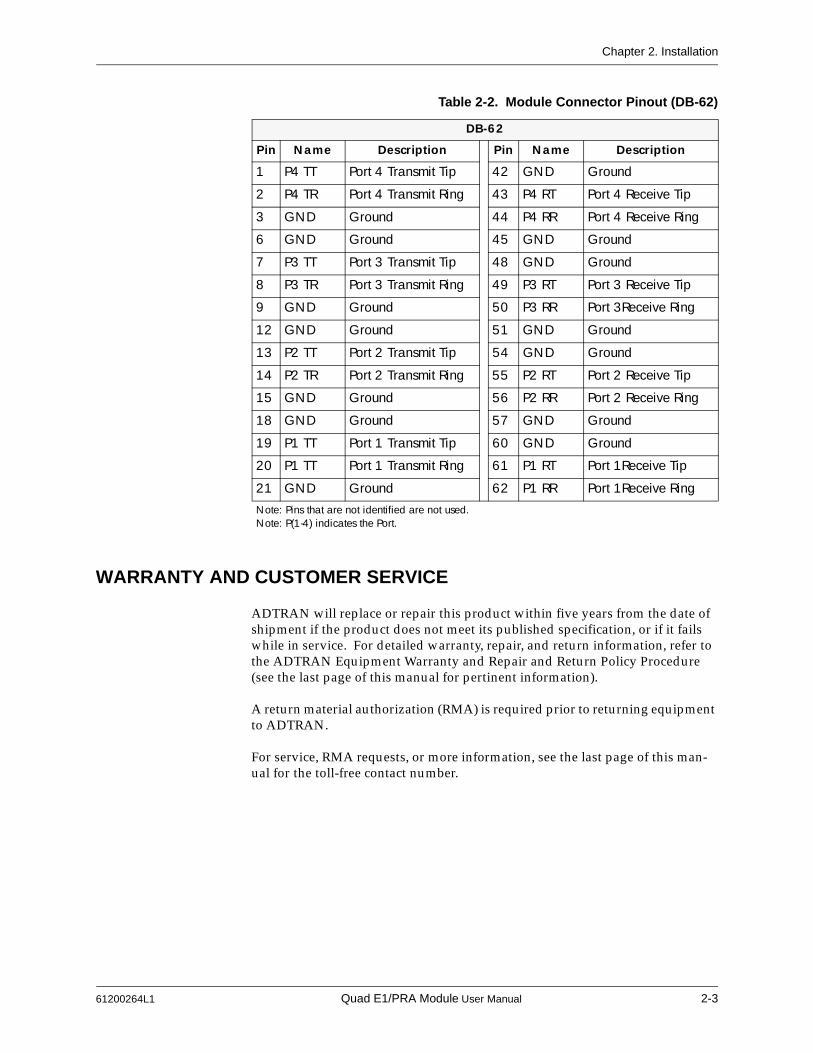
Each port of the Quad E1/PRA Module offers a single DB-15 for connecting to the E1 or PRA circuit. Table 2-1 and Table 2-2 give the pinouts for the DB-15 connector and for the DB-62 connector on the module.
QUAD E1-PRA
Table 2-1. Network Connection Pinout (DB-15)
DB-15
Pin Name Description
1 RT Receive Tip
2 GND Ground
3 TT Transmit Tip
4 GND Ground
5 GND Ground
7 GND Ground
9 RR Receive Ring
11 TR Transmit RingNote: Pins that are not identified are not used.
2-2 Quad E1/PRA Module User Manual 61200264L1
Chapter 2. Installation
WARRANTY AND CUSTOMER SERVICE
ADTRAN will replace or repair this product within five years from the date of shipment if the product does not meet its published specification, or if it fails while in service. For detailed warranty, repair, and return information, refer to the ADTRAN Equipment Warranty and Repair and Return Policy Procedure (see the last page of this manual for pertinent information).
A return material authorization (RMA) is required prior to returning equipment to ADTRAN.
For service, RMA requests, or more information, see the last page of this man-ual for the toll-free contact number.
Table 2-2. Module Connector Pinout (DB-62)
DB-62
Pin Name Description Pin Name Description
1 P4 TT Port 4 Transmit Tip 42 GND Ground
2 P4 TR Port 4 Transmit Ring 43 P4 RT Port 4 Receive Tip
3 GND Ground 44 P4 RR Port 4 Receive Ring
6 GND Ground 45 GND Ground
7 P3 TT Port 3 Transmit Tip 48 GND Ground
8 P3 TR Port 3 Transmit Ring 49 P3 RT Port 3 Receive Tip
9 GND Ground 50 P3 RR Port 3Receive Ring
12 GND Ground 51 GND Ground
13 P2 TT Port 2 Transmit Tip 54 GND Ground
14 P2 TR Port 2 Transmit Ring 55 P2 RT Port 2 Receive Tip
15 GND Ground 56 P2 RR Port 2 Receive Ring
18 GND Ground 57 GND Ground
19 P1 TT Port 1 Transmit Tip 60 GND Ground
20 P1 TT Port 1 Transmit Ring 61 P1 RT Port 1Receive Tip
21 GND Ground 62 P1 RR Port 1Receive RingNote: Pins that are not identified are not used.Note: P(1-4) indicates the Port.
61200264L1 Quad E1/PRA Module User Manual 2-3

Chapter 2. Installation
2-4 Quad E1/PRA Module User Manual 61200264L1

Chapter 3 Operation
OVERVIEW
The Quad E1/PRA Module can be configured and controlled from a variety of sources, including the following:
• The ATLAS front panel, providing minimal configuration and status sup-port
• The terminal menu, allowing detailed configuration, status, and diagnostics
• SNMP, used primarily for reporting alarm conditions and system status
You can access the terminal menu using either a VT-100 terminal attached to the ATLAS Base Unit’s control port or a Telnet session established through the Base Unit’s Ethernet port. Detailed instructions on each of the supported manage-ment approaches are presented in the ATLAS User Manual. The remainder of this section describes the menu items available when managing the Quad E1/PRA Module via the terminal menu.
Security Passwords
To edit items in the terminal menu, you must have the appropriate password level. Each menu description in this section indicates the password level required for write and read access. See “Access Passwords” in the ATLAS User Manual for detailed information on working with passwords.
Security level 0 users can view and edit every available field. Security level 5 users can view any field but cannot edit.
TERMINAL MENU STRUCTURE
ATLAS uses a form of hierarchical menus to access all features. The topmost menu level leads to submenus which are grouped by functionality. All menu items display in the terminal window.
Refer to the ATLAS User Manual for detailed instructions on navigating through the terminal menu.
61200264L1 Quad E1/PRA Module User Manual 3-1

Chapter 3. Operation
The ATLAS system controller automatically detects the presence of the Quad E1/PRA Module when it is installed in the system. To see the menus for the Quad E1/PRA Module via the terminal menu, use the arrow keys to scroll to the Modules menu and press Enter to access the module choices. Figure 3-1 shows the Modules menu. The following sections describe all the ATLAS Mod-ules menu options.
Figure 3-1. Modules Menu
MENU DESCRIPTION
> SLT Read security: 5(Slot) Displays the number of available option slots in the ATLAS chassis. Slot 0 refers to the ATLAS Base Unit. This field is read-only.
> TYPE Write security: 3; Read security: 5Displays the type of module actually installed in the slot or the type of module you plan to install in the slot. If a Quad E1/PRA Module is installed, the Type field automatically defaults to E1/PRI-4 (the Quad E1/PRI Module). You can use this field to preconfigure a system before installing modules by specifying the module that you want to install into each slot.
To help you follow the terminal menu hierarchy, the following notations are used.
>MENUS» Submenus»» Sub-submenus
3-2 Quad E1/PRA Module User Manual 61200264L1
Chapter 3. Operation
> MENU Displays additional status and configuration menus for the selected module. (To access the submenus for this item, use the arrow keys to scroll to the Menu column for the module you want to edit, and press Enter.) For detailed informa-tion on each submenu item, see Menu Options on page 3-4.
> ALARM Read security: 5Displays whether there is an alarm condition on the Quad E1/PRA Module. Press Enter in this field to activate the menu.
> TEST Read security: 5Displays whether the Quad E1/PRA Module is executing a test. Press Enter in this field to activate the menu.
> STATE Write security: 3; Read security: 5Displays whether the module is online or offline. Even though a module is physically installed, it must be marked Online for it to be considered an avail-able resource. This field allows an installed module to be marked Offline , which may be useful in system troubleshooting. If you choose Offline , the module will not be in alarm condition, but will display Offline .
> STATUS Read security: 5Read-only field that presents status information on the Quad E1/PRA Module. The following messages may display:
If you install one type of module in a slot, and then want to install a differ-ent type of module in the slot, you must set this field to Empty before selecting the other module type.
If a module is installed, the module type automatically displays the name of the installed module, and cannot be set to any other option.
A module must be in the Online state in order for ATLAS to use the mod-ule for any data bandwidth.
Online The module is enabled and is responding to the system con-troller’s status polls. This is the normal response of the sys-tem.
No Response The module is enabled, but is not responding to the system controller’s status polls. This response indicates either a prob-lem in the system or that the module is not installed.
Empty The system controller has not detected the presence of a mod-ule in the slot, nor has a module been manually enabled for this option slot.
61200264L1 Quad E1/PRA Module User Manual 3-3
Chapter 3. Operation
> REV Read security: 5(Hardware Revision) Read-only field that displays the hardware revision of the Quad E1/PRA Module.
MENU OPTIONS
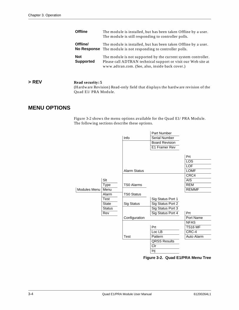
Figure 3-2 shows the menu options available for the Quad E1/PRA Module. The following sections describe these options.
Figure 3-2. Quad E1/PRA Menu Tree
Offline The module is installed, but has been taken Offline by a user. The module is still responding to controller polls.
Offline/No Response
The module is installed, but has been taken Offline by a user. The module is not responding to controller polls.
Not Supported
The module is not supported by the current system controller. Please call ADTRAN technical support or visit our Web site at www.adtran.com. (See, also, inside back cover.)
Part NumberInfo Serial Number
Board RevisionE1 Framer Rev
PrtLOSLOF
Alarm Status LOMFCRC4
Slt AISType TS0 Alarms REM
Modules Menu Menu REMMFAlarm TS0 StatusTest Sig Status Port 1State Sig Status Sig Status Port 2Status Sig Status Port 3Rev Sig Status Port 4 Prt
Configuration Port NameNFAS
Prt TS16 MFLoc LB CRC-4
Test Pattern Auto AlarmQRSS ResultsClr Inj
3-4 Quad E1/PRA Module User Manual 61200264L1
Chapter 3. Operation
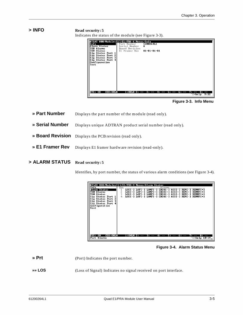
> INFO Read security: 5Indicates the status of the module (see Figure 3-3).
» Part Number Displays the part number of the module (read only).
» Serial Number Displays unique ADTRAN product serial number (read only).
» Board Revision Displays the PCB revision (read only).
» E1 Framer Rev Displays E1 framer hardware revision (read-only).
> ALARM STATUS Read security: 5
Identifies, by port number, the status of various alarm conditions (see Figure 3-4).
Figure 3-4. Alarm Status Menu
» Prt (Port) Indicates the port number.
»» LOS (Loss of Signal) Indicates no signal received on port interface.
Figure 3-3. Info Menu
61200264L1 Quad E1/PRA Module User Manual 3-5

Chapter 3. Operation
»» LOF (Loss of Frame) Indicates that receiver is unable to synchronize to the FAS fram-ing pattern of the received signal.
»» LOMF (Loss of Multi-Frame) Indicates that receiver is unable to synchronize to the TS16 multi-frame pattern of the received signal.
»» CRC4 (Loss of CRC-4 Framing) Indicates that receiver is unable to synchronize to the CRC-4 frame pattern of the received signal.
»» AIS (Alarm Indication Signal Received) Indicates that all ones are being received.
»» REM (Remote Frame Alarm) Indicates loss of frame alarm being received from far end.
»» REMMF (Remote Multi-Frame Alarm) Indicates loss of multi-frame alarm being received from far end.
> TS0 ALARMS Read Security: 5For each TS0 (Ports 1—4), displays an appropriate alarm code. This set of possi-ble alarms is comprised mainly of alarms that indicate the failure of some upper-level protocol configured to be carried in the TS0 (read only). See Figure 3-5.
Figure 3-5. TS0 Alarms Menu
> TS0 STATUS Read security: 5For each TS0 (Ports 1—4), displays a code indicating the current usage for the TS0 (read only). See Figure 3-6.
3-6 Quad E1/PRA Module User Manual 61200264L1

Chapter 3. Operation
Figure 3-6. TS0 Status Menu
The current usage codes are as follow:
> SIG STATUS Read security: 5(Ports 1—4) Displays the state of the A/B/C/D signaling bits for Ports 1—4 of the Quad E1/PRA Module. Dashes indicate TS0s where signaling is not being transferred by the ATLAS (read only). See Figure 3-7.
Figure 3-7. Sig Status Menu
> CONFIGURATION All of the following configurable parameters apply regardless of whether the port is connected to a Primary Rate Access or channelized E1 circuit (see Figure 3-8).
- Inactive O Off hook detected
A Active call on this TS0 R Ringing detected
D Active ISDN D Channel TS0 F Framing TS0
M Maintenance TS0 S Signaling TS0
N Dedicated TS0
61200264L1 Quad E1/PRA Module User Manual 3-7

Chapter 3. Operation
Figure 3-8. Configuration Menu
» Prt Read security: 5Displays the port number.
» Port Name Write security: 3; Read security: 5Enter any text up to 16 characters to uniquely identify each port on the Quad E1/PRA Module.
» NFAS Write security: 3; Read security: 5If enabled, the network interface receiver requires the NFAS word (TS0 0 in odd frames) and the FAS word (TS0 0 in even frames) for frame sync. When dis-abled, only the FAS word is needed for frame sync.
» TS16 MF Write security: 3; Read security: 5If enabled, the receiver requires MFAS word in TS16 to achieve sync. The trans-mitter outputs MFAS word in TS16 (see also, CAS on page 3-11).
» CRC-4 Write security: 3; Read security: 5Transmits the CRC-4 checksum bits in the outgoing E1 data stream, when enabled. Also, checks the received signal for errors.
» Auto Alarm Write security: 3; Read security: 5Transmits a remote alarm when framing is lost (when Red Alarm Generation is on), and transmits an AIS alarm when all ones are received (when RCM AIS Generation is on).
» Code Write security: 3; Read security: 5Allows selection of line coding. HDB3 is normally the only coding method used on public networks. AMI may be selected for testing purposes.
» TS0 Spare Write security: 3; Read security: 5Allows setting of the TS0 spare bits, Sa4 (MXB) to Sa8 (LSB).
» Intl Bit Write security: 3; Read security: 5Allows setting of International Spare Bit.
3-8 Quad E1/PRA Module User Manual 61200264L1
Chapter 3. Operation
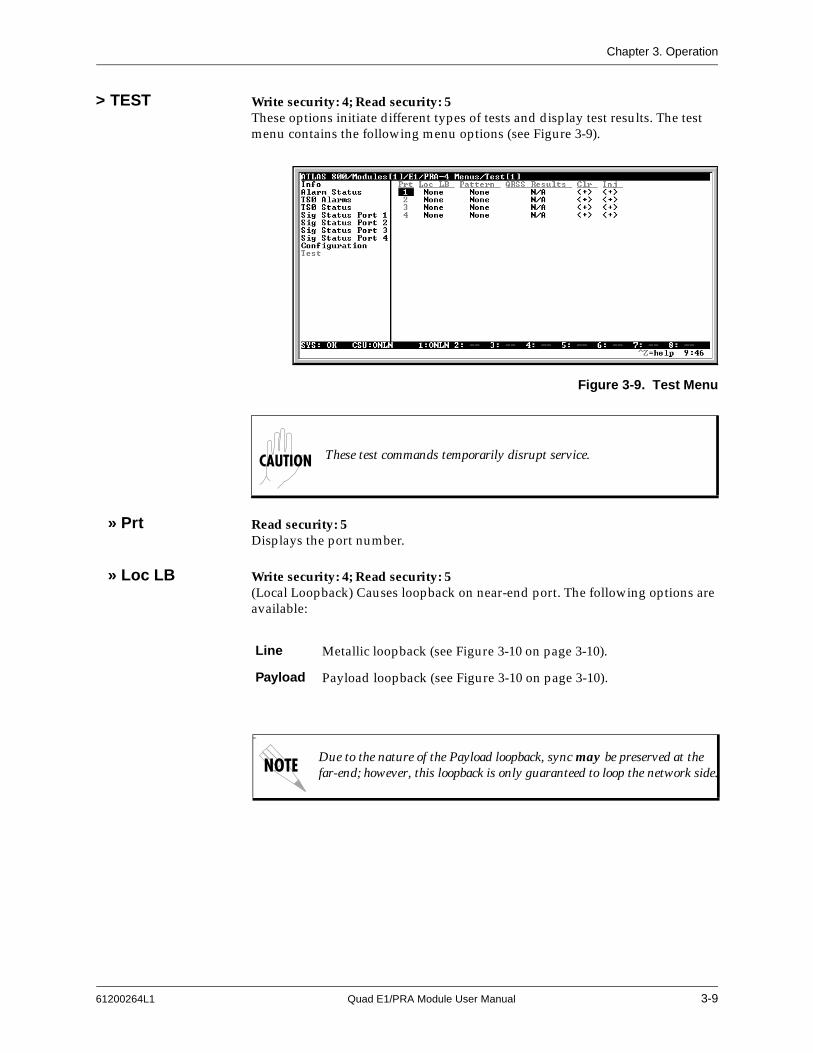
> TEST Write security: 4; Read security: 5These options initiate different types of tests and display test results. The test menu contains the following menu options (see Figure 3-9).
Figure 3-9. Test Menu
» Prt Read security: 5Displays the port number.
» Loc LB Write security: 4; Read security: 5(Local Loopback) Causes loopback on near-end port. The following options are available:
These test commands temporarily disrupt service.
Line Metallic loopback (see Figure 3-10 on page 3-10).
Payload Payload loopback (see Figure 3-10 on page 3-10).
far-
Due to the nature of the Payload loopback, sync may be preserved at the far-end; however, this loopback is only guaranteed to loop the network side.
61200264L1 Quad E1/PRA Module User Manual 3-9

Chapter 3. Operation
Figure 3-10. Network Loopback Test
» Pattern Write security: 4; Read security: 5Test pattern to be transmitted out the port. The following options are available:
» QRSS Results Write security: 4; Read security: 5(Test Pattern Results) Indicates sync and errors of received data pattern.
» Clr Write security: 4; Read security: 5(Test Pattern Results Clear) Results clear - clears error counters on test pattern results menu.
» Inj Write security: 4; Read security: 5(Test Pattern Error Inject) Injects errors into transmitted test pattern.
ADDITIONAL ATLAS FEATURES
In addition to the Quad E1/PRA Module menu items, additional ATLAS menu items may be operated in conjunction with the Quad E1/PRA Module. These are Factory Restore , Run Self Test , and Dedicated Maps .
> FACTORY RESTORE
Factory Restore , a submenu of the ATLAS front panel main menu item Utilities (UTIL), restores the factory installed default setting for all Quad E1/PRA Mod-ule parameters. When Factory Restore displays, place the cursor on it and press Enter. The unit is restored to preset factory defaults and returns to the main ATLAS menu.
> RUN SELF TEST Run Self Test , a submenu of the ATLAS main menu item Test , executes both the Quad E1/PRA Module internal test and the ATLAS internal test. For addi-tional information on Run Self Test see the ATLAS 800 User Manual. When Run
Quad E1/PRA
DS1
NI CSU
Line Loopback
Payload Loopback
All ones framed ones
All zeros framed zeros
QRSS pseudo-random pattern with suppression of excess zeros
3-10 Quad E1/PRA Module User Manual 61200264L1

Chapter 3. Operation
Self Test is displayed, place the cursor on it and press Enter to execute the test. The results of the self-test are displayed in the LCD.
> DEDICATED MAPS
TS0s are used as defined in the Dedicated Map . See the ATLAS 800 User Manual for detailed information.
»» CAS When CAS (channel-associated signaling) is turned on, TS16 MF is turned on in the Configuration menu and Signaling is propagated across the link (see Figure 3-11 on page 3-11). When CAS is turned off, Signaling is no longer propagated. If MFAS framing is no longer required, turn off TS16 MF in the Config menu (see also, TS16 MF on page 3-8).
Figure 3-11. Dedicated Map View with CAS Turned On
Defining a port as a E1 or PRA is determined by the way it is assigned in the Dedicated Map or in the Dial Plan.
61200264L1 Quad E1/PRA Module User Manual 3-11

Chapter 3. Operation
3-12 Quad E1/PRA Module User Manual 61200264L1
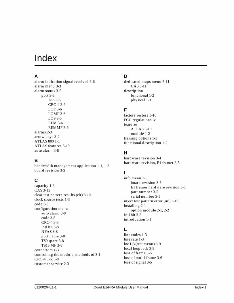
Index
Aalarm indication signal received 3-6alarm menu 3-3alarm status 3-5
port 3-5AIS 3-6CRC-4 3-6LOF 3-6LOMF 3-6LOS 3-5REM 3-6REMMF 3-6
alarms 2-3arrow keys 3-2ATLAS 800 1-1ATLAS features 3-10auto alarm 3-8
Bbandwidth management application 1-1, 1-2board revision 3-5
Ccapacity 1-3CAS 3-11clear test pattern results (clr) 3-10clock source tests 1-3code 3-8configuration menu
auto alarm 3-8code 3-8CRC-4 3-8Intl bit 3-8NFAS 3-8port name 3-8TS0 spare 3-8TS16 MF 3-8
connectors 1-3controlling the module, methods of 3-1CRC-4 3-6, 3-8customer service 2-3
Ddedicated maps menu 3-11
CAS 3-11description
functional 1-2physical 1-3
Ffactory restore 3-10FCC regulations ivfeatures
ATLAS 3-10module 1-2
framing options 1-3functional description 1-2
Hhardware revision 3-4hardware revision, E1 framer 3-5
Iinfo menu 3-5
board revision 3-5E1 framer hardware revision 3-5part number 3-5serial number 3-5
inject test pattern error (inj) 3-10installing 2-1
option module 2-1, 2-2Intl bit 3-8introduction 1-1
Lline codes 1-3line rate 1-3loc LB (test menu) 3-9local loopback 3-9loss of frame 3-6loss of multi-frame 3-6loss of signal 3-5
61200264L1-1 Quad E1/PRA Module User Manual Index-1

Index
Mmain menu
alarm status 3-5, 3-6configuration menu 3-7
auto alram 3-8code 3-8CRC-4 3-8Intl bit 3-8NFAS 3-8port 3-8port name 3-8TS0 spare 3-8TS16 MF 3-8
dedicated maps menuCAS 3-11
rev 3-4sig status 3-7test menu 3-9
clr 3-10inj 3-10loc LB 3-9pattern 3-10port 3-9QRSS results 3-10
TS0 alarms 3-6TS0 status 3-6
main menusalarm 3-3info 3-5menu 3-3slt 3-2state 3-3status 3-3, 3-4test 3-3type 3-2
menu 3-3description 3-2modules 3-2traversal 3-2
menu tree 3-4module features 1-2modules menu 3-2
Nnetwork pinouts 2-2, 2-3NFAS 3-8
Ooperation 3-1operation alarms 2-3overview
operation 3-1
Ppart number 3-5pattern (test menu) 3-10physical description 1-3pinouts 2-2, 2-3port name (configuration menu) 3-8
QQRSS results 3-10
Rremote frame alarm 3-6remote multi-frame alarm 3-6restore factory defaults 3-10RMA requests 2-3run self test 3-10
Ssecurity passwords 3-1self test 3-10serial number 3-5service 2-3signaling status 3-7slt menu 3-2specifications 1-3state menu 3-3status menu 3-3
empty 3-3no response 3-3not supported 3-4offline 3-4offline/no response 3-4online 3-3
support 2-3
Ttechnical support 2-3terminal menu structure 3-1terminating impedance 1-3test 3-9test menu 3-3
clr 3-10inj 3-10loc LB 3-9pattern 3-10port 3-9QRSS results 3-10
test pattern 3-10error inject 3-10
TS0 alarms 3-6TS0 spare 3-8
Index-2 Quad E1/PRA Module User Manual 61200264L1-1
Index
TS0 status 3-6usage codes 3-7
TS16 MF 3-8type menu 3-2typical applications 1-1
Wwarranty 2-3wiring 2-2
YY2K readiness iii
61200264L1-1 Quad E1/PRA Module User Manual Index-3

Index
Index-4 Quad E1/PRA Module User Manual 61200264L1-1
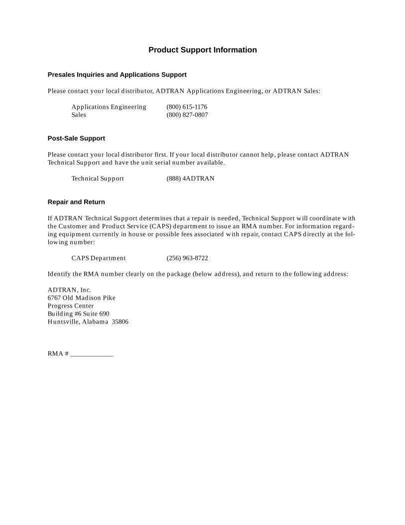
Product Support Information
Presales Inquiries and Applications Support
Please contact your local distributor, ADTRAN Applications Engineering, or ADTRAN Sales:
Applications Engineering (800) 615-1176Sales (800) 827-0807
Post-Sale Support
Please contact your local distributor first. If your local distributor cannot help, please contact ADTRAN Technical Support and have the unit serial number available.
Technical Support (888) 4ADTRAN
Repair and Return
If ADTRAN Technical Support determines that a repair is needed, Technical Support will coordinate with the Customer and Product Service (CAPS) department to issue an RMA number. For information regard-ing equipment currently in house or possible fees associated with repair, contact CAPS directly at the fol-lowing number:
CAPS Department (256) 963-8722
Identify the RMA number clearly on the package (below address), and return to the following address:
ADTRAN, Inc.6767 Old Madison PikeProgress CenterBuilding #6 Suite 690Huntsville, Alabama 35806
RMA # _____________