QTERM -A12 TERMINAL HARDWARE MANUAL - Beijer...
38
QTERM ® -A12 TERMINAL HARDWARE MANUAL BEIJER ELECTRONICS 2212 South West Temple #50 Salt Lake City, Utah 84115-2648 USA Phone 801-466-8770 Fax 801-466-8792 Email [email protected] Web http://www. beijerelectronicsinc .com M01-061-00 Rev 02
Transcript of QTERM -A12 TERMINAL HARDWARE MANUAL - Beijer...
QTERM®-A12 TERMINALHARDWARE MANUAL
BEIJER ELECTRONICS2212 South West Temple #50
Salt Lake City, Utah 84115-2648USA
Phone 801-466-8770Fax 801-466-8792
Email [email protected] http://www.beijerelectronicsinc.comM01-061-00 Rev 02

Copyright © 2011 Beijer Electronics. Printed in the USA. All rights reserved. No part of this publication may be reproduced, in any form or by any means with-out prior written permission from Beijer Electronics.
Qlarity and QTERM are registered trademarks of Beijer Electronics.Microsoft, Windows, Windows NT, Windows 2000, Windows XP, Vista, ActiveSync and their respective logos are registered trademarks of Microsoft Corpora-tion in the United States and other countries.All other brand and product names used in this manual are trademarks or registered trademarks of their respective companies.
Manual updated 6 September 2011.

FCC Compliance Information
This equipment has been tested and found to comply with the limits for a Class A digital device, pursuant to part 15 of the FCCRules. These limits are designed to provide reasonable protection against harmful interference when the equipment is operated ina commercial environment. This equipment generates, uses and can radiate radio frequency energy and, if not installed and usedin accordance with the instruction manual, may cause harmful interference to radio communications. Operation of this equipmentin a residential area is likely to cause harmful interference in which case the user will be required to correct the interference attheir own expense.
Additionally, the QTERM-A12 may contain the following FCC module-certified components depending on product configura-tion: QOQWT12 or Q72WLC300GRS.

Notes

QTERM-A12 Terminal i
CONTENTS
CHAPTER 1. INTRODUCTION . . . . . . . . . . . . . . . . . . . . . . . . . . . . . . . . . . . . . . . . . . . . . . . . . .1
CHAPTER 2. SAFETY SUMMARY . . . . . . . . . . . . . . . . . . . . . . . . . . . . . . . . . . . . . . . . . . . . . . .3
CHAPTER 3. APPLYING POWER . . . . . . . . . . . . . . . . . . . . . . . . . . . . . . . . . . . . . . . . . . . . . . .53.1 Connecting to Earth Ground . . . . . . . . . . . . . . . . . . . . . . . . . . . . . . . . . . . . . . . . . . . .53.2 Primary Serial Port Connector for Power Input . . . . . . . . . . . . . . . . . . . . . . . . . . . . .63.3 Terminal Strip for Power Input. . . . . . . . . . . . . . . . . . . . . . . . . . . . . . . . . . . . . . . . . .63.4 Optional Power-over-Ethernet Interface. . . . . . . . . . . . . . . . . . . . . . . . . . . . . . . . . . .73.5 Powering On the Terminal for the First Time . . . . . . . . . . . . . . . . . . . . . . . . . . . . . .8
CHAPTER 4. HARDWARE DESCRIPTION AND ARCHITECTURE . . . . . . . . . . . . . . . . . . . . . . .94.1 User Interface . . . . . . . . . . . . . . . . . . . . . . . . . . . . . . . . . . . . . . . . . . . . . . . . . . . . . . .94.2 Processor . . . . . . . . . . . . . . . . . . . . . . . . . . . . . . . . . . . . . . . . . . . . . . . . . . . . . . . . . . .94.3 System and Application Memory . . . . . . . . . . . . . . . . . . . . . . . . . . . . . . . . . . . . . . . .94.4 Serial Communications . . . . . . . . . . . . . . . . . . . . . . . . . . . . . . . . . . . . . . . . . . . . . . .104.5 Network. . . . . . . . . . . . . . . . . . . . . . . . . . . . . . . . . . . . . . . . . . . . . . . . . . . . . . . . . . .104.6 Speaker . . . . . . . . . . . . . . . . . . . . . . . . . . . . . . . . . . . . . . . . . . . . . . . . . . . . . . . . . . .104.7 Power Supply . . . . . . . . . . . . . . . . . . . . . . . . . . . . . . . . . . . . . . . . . . . . . . . . . . . . . .114.8 Housing . . . . . . . . . . . . . . . . . . . . . . . . . . . . . . . . . . . . . . . . . . . . . . . . . . . . . . . . . . .11
CHAPTER 5. INSTALLATION . . . . . . . . . . . . . . . . . . . . . . . . . . . . . . . . . . . . . . . . . . . . . . . . .135.1 Cutting Out for Panel Mount . . . . . . . . . . . . . . . . . . . . . . . . . . . . . . . . . . . . . . . . . .14
5.1.1 Standard Version Cutout . . . . . . . . . . . . . . . . . . . . . . . . . . . . . . . . . . . . . . . . .145.1.2 Modular Version Cutout . . . . . . . . . . . . . . . . . . . . . . . . . . . . . . . . . . . . . . . . .15
5.2 Installing the Terminal . . . . . . . . . . . . . . . . . . . . . . . . . . . . . . . . . . . . . . . . . . . . . . .165.2.1 Standard Version Installation . . . . . . . . . . . . . . . . . . . . . . . . . . . . . . . . . . . . .165.2.2 Modular Version Installation. . . . . . . . . . . . . . . . . . . . . . . . . . . . . . . . . . . . . .17
CHAPTER 6. SPECIFICATIONS . . . . . . . . . . . . . . . . . . . . . . . . . . . . . . . . . . . . . . . . . . . . . . . .19
CHAPTER 7. MECHANICAL . . . . . . . . . . . . . . . . . . . . . . . . . . . . . . . . . . . . . . . . . . . . . . . . . .237.1 Layout and Dimensions . . . . . . . . . . . . . . . . . . . . . . . . . . . . . . . . . . . . . . . . . . . . . .23
7.1.1 Standard Version . . . . . . . . . . . . . . . . . . . . . . . . . . . . . . . . . . . . . . . . . . . . . . .237.1.2 Modular Version . . . . . . . . . . . . . . . . . . . . . . . . . . . . . . . . . . . . . . . . . . . . . . .26
7.2 Connector Pinouts . . . . . . . . . . . . . . . . . . . . . . . . . . . . . . . . . . . . . . . . . . . . . . . . . . .287.2.1 Primary Serial Port . . . . . . . . . . . . . . . . . . . . . . . . . . . . . . . . . . . . . . . . . . . . .287.2.2 Secondary Serial Port . . . . . . . . . . . . . . . . . . . . . . . . . . . . . . . . . . . . . . . . . . .297.2.3 Terminal Strip for Power Input . . . . . . . . . . . . . . . . . . . . . . . . . . . . . . . . . . . .297.2.4 Ethernet Port . . . . . . . . . . . . . . . . . . . . . . . . . . . . . . . . . . . . . . . . . . . . . . . . . .307.2.5 USB 2.0 Ports . . . . . . . . . . . . . . . . . . . . . . . . . . . . . . . . . . . . . . . . . . . . . . . . .31

Contents
ii QTERM-A12 Terminal
Notes

QTERM-A12 Terminal 1
CHAPTER 1
INTRODUCTION
The QTERM®-A12 is a rugged graphic human-machine interface terminal for use in a wide range of commercial and industrial applications. It has been designed with a robust set of industrial-grade features and options.
• Windows® Embedded CE 6.0 operating system
• Support for application development with industry standard tools such as Microsoft® Visual Studio 2005 or 2008
• Marvell® PXA300 processor (ARMV5TE) with Intel XScale™ technology running at 624 MHz
• 4 Gbytes non-volatile storage (with support for larger capacities)
• 128 Mbytes of DDR SDRAM
• Two USB 2.0 full speed host ports with built-in support for standard USB keyboards, mice and memory devices
• 10/100Base-T wired Ethernet
• Two serial ports: one EIA-232/422/485 (software configurable) and one EIA-232 serial port
• Bright 307 mm (12.1") TFT color SVGA (800 x 600) display with 450 nit LED backlight
• Analog-resistive 5-wire touch screen for rugged applications
• Built-in speaker (behind panel)
• Terminal strip for power input (alternate power input on COM1 DB9)
• 10 to 32 VDC input voltage range
• Built-in protection from power transients and spikes, reverse voltage and overvoltage
• Optional Power-over-Ethernet (PoE) interface
• Wide operating temperature of -30 to 70 °C, storage temperature of -40 to 85 °C
• Tough industrial grade polymer housing

Introduction
2 QTERM-A12 Terminal
Notes
QTERM-A12 Terminal 3
CHAPTER 2
SAFETY SUMMARY
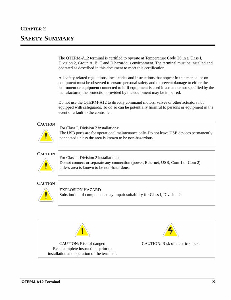
The QTERM-A12 terminal is certified to operate at Temperature Code T6 in a Class I, Division 2, Group A, B, C and D hazardous environment. The terminal must be installed and operated as described in this document to meet this certification.
All safety related regulations, local codes and instructions that appear in this manual or on equipment must be observed to ensure personal safety and to prevent damage to either the instrument or equipment connected to it. If equipment is used in a manner not specified by the manufacturer, the protection provided by the equipment may be impaired.
Do not use the QTERM-A12 to directly command motors, valves or other actuators not equipped with safeguards. To do so can be potentially harmful to persons or equipment in the event of a fault to the controller.
CAUTIONFor Class I, Division 2 installations:The USB ports are for operational maintenance only. Do not leave USB devices permanently connected unless the area is known to be non-hazardous.
CAUTIONFor Class I, Division 2 installations:Do not connect or separate any connection (power, Ethernet, USB, Com 1 or Com 2)unless area is known to be non-hazardous.
CAUTION
EXPLOSION HAZARDSubstitution of components may impair suitability for Class I, Division 2.
CAUTION: Risk of danger.Read complete instructions prior to
installation and operation of the terminal.
CAUTION: Risk of electric shock.

Safety Summary
4 QTERM-A12 Terminal
Notes

QTERM-A12 Terminal 5
CHAPTER 3
APPLYING POWER
Power is supplied to the QTERM-A12 terminal via the COM1 serial port connector or the 3-pin power terminal strip for input power, return and chassis ground. The QTERM-A12 may also be equipped with an optional Power-over-Ethernet (PoE) interface. When powered by the 3-pin power terminal strip or the COM1 serial port, the QTERM-A12 has a 10- to 32-volt DC input range and can be powered directly from a 12- or 24-volt DC power supply (the current will vary depending on the input voltage; see table below).
3.1 Connecting to Earth Ground
NOTE ☞ The chassis ground connection of the QTERM-A12 is electrically connected to the exposed conductive parts of the QTERM-A12 for safety purposes. The chassis ground connection MUST be connected to an external protective earthing system.
The QTERM-A12 has a chassis ground terminal and a chassis ground connection on the 3-pin power terminal strip on the back of the terminal. (See Figure 6 on page 24 and Figure 15 on page 29 for the location of the chassis ground terminal and the 3-pin power terminal strip.) The terminal should be connected to earth ground (protective earth). The chassis ground is not con-nected to signal common of the terminal. Maintaining isolation between earth ground and signal common is not required to operate the terminal; however, other equipment connected to the terminal may require isolation between signal common and earth ground. To maintain iso-
CAUTIONFor Class I, Division 2 installations:Do not connect or disconnect cables while power is applied unless the area is known to be non-hazardous.
Power Consumption
Terminal 12 VDC 24 VDC PoE (48 VDC)
Standby1
1. Standby power consumption is measured when the display has been powered down and theoperating system has entered system idle mode.
1.3 W 1.6 W 3.0 W
Typical2
2. Typical power consumption is measured when the display is at full brightness and a polygondrawing application is running.
8.5 W 9.1 W 10.5 W
Estimated Maximum3
3. Estimated maximum power consumption is measured with serial, USB and Ethernet commu-nications active. In addition, several applications are running including video with full volumeand two USB mass storage loads are being powered.
12.1 W 13.1 W 14.2 W
Primary Serial Port Connector for Power Input Applying Power
6 QTERM-A12 Terminal
lation between signal common and earth ground, care must be taken when connections are made to the terminal. For example, a power supply with isolation between its signal common and earth ground must be used. Also, plugging in a serial cable or a USB cable may connect signal common and earth ground.
The serial cable shield or the USB shield may be connected to earth ground at the host. The serial cable or the USB shield, in turn, may also be connected to signal common.
3.2 Primary Serial Port Connector for Power Input
Power can be supplied to the terminal through pin 9 and ground return through pin 5 of the COM1 serial port connector.
3.3 Terminal Strip for Power Input
The 3-pin terminal strip is used to provide input voltage and ground to the terminal. The termi-nal strip provides a chassis ground connection. The chassis ground pin is isolated from the sys-tem ground of the terminal.
WARNINGAlthough the terminal includes protection circuitry to prevent power supply contention, power should not be connected to the 3-pin terminal strip or the RJ45 PoE interface while power is applied to the DB9 connector.
WARNINGAlthough the terminal includes protection circuitry to prevent power supply contention, power should not be connected to the DB9 connector or the RJ45 PoE interface while power is applied to the 3-pin terminal strip.
WARNINGQTERM-A12 power must come from an SELV (Safety Extra Low Voltage) power source and should have a current limit on its output of 5 Amperes. It must provide a minimum of 10 volts DC power and be limited to a maximum of 32 volts DC. Limiting may be inherent to the supply or may be provided by supplementary overcurrent devices. If the QTERM-A12 does not respond or exhibits abnormal behavior on power up, disconnect power and contact Beijer Electronics for technical support.
Applying Power Optional Power-over-Ethernet Interface
QTERM-A12 Terminal 7
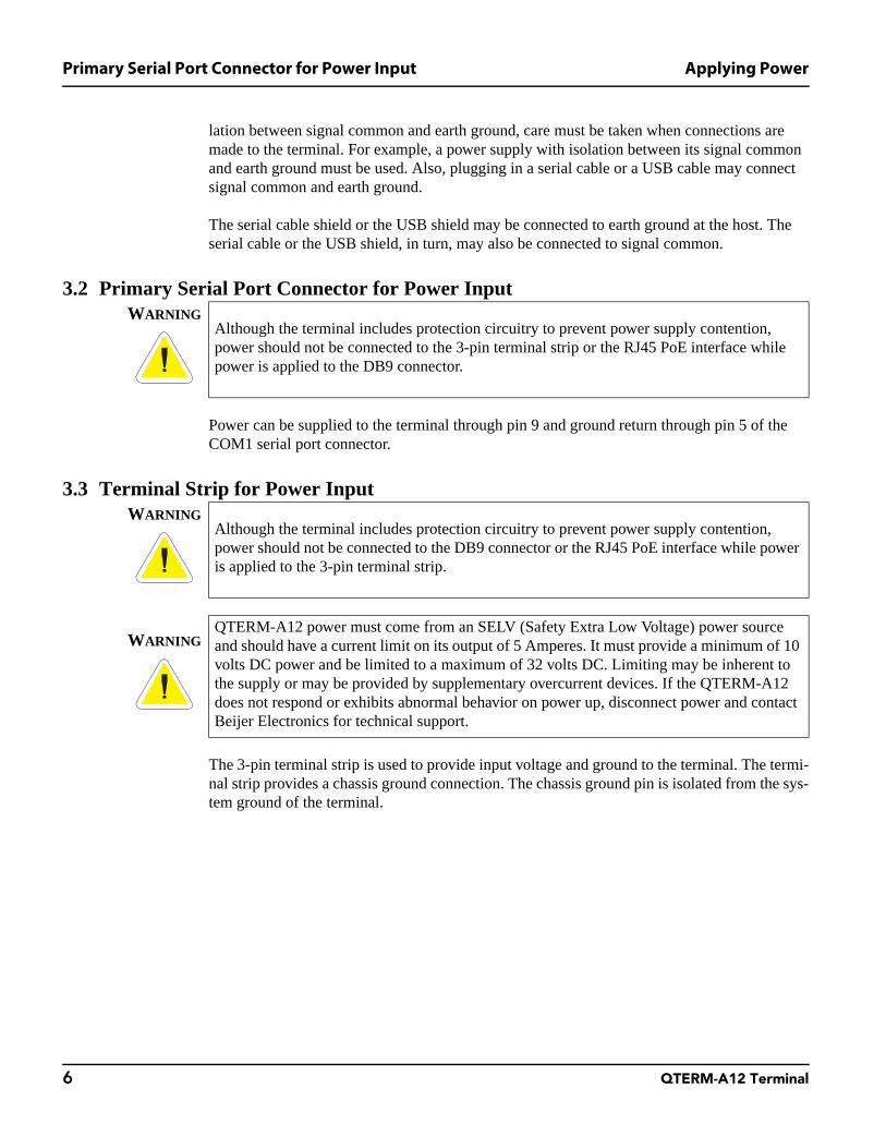
3.4 Optional Power-over-Ethernet Interface
The QTERM-A12 may be equipped with an optional Power-over-Ethernet (PoE) interface. This interface may be used to power the terminal by connecting a PoE equipped Power Sourc-ing Equipment (PSE) to the RJ45 connector on the rear of the terminal.
The QTERM-A12 PoE interface is functional with both IEEE 802.3af-2003 and 802.3at-2009 standards. If the terminal is connected to an IEEE 802.3af-2003 compliant network connection the terminal will operate as a Type 1 Class 4 PoE device in a low-power condition not exceed-ing 13 Watts average power consumption. The terminal will automatically disable both USB ports while operating as a Type 1 Powered Device (PD) to ensure that the total average power consumption remains lower than 13 Watts.
If the QTERM-A12 is connected to an IEEE 802.3at-2009 compliant network connection all included features will be operational. In this mode, the terminal will complete 2-event classifi-cation as specified by IEEE 802.3at-2009 and operate as a Type 2 Class 4 PoE Powered Device (PD).
The QTERM-A12 will also operate from a non-compliant (simple Power-over-Ethernet with no classification) PSE source if the source can supply up to 600 mA and maintain between 37.0 and 57.0 volts measured at the RJ45 connector on the terminal.
The QTERM-A12 will accept either Mode A or Mode B power connections as specified by IEEE 802.3at-2009. The following table provides pinout information for both of these modes. The polarity may be reversed in either mode.
NOTE ☞ The chassis ground connection MUST be connected to an external protective earthing system. See section 3.1, “Connecting to Earth Ground” for more information.
WARNINGAlthough the terminal includes protection circuitry to prevent power supply contention, power should not be connected to the 3-pin terminal strip or the DB9 connector while power is applied to the RJ45 PoE interface.
Port Pin Assignment
Conductor Mode A Mode B
1 Tx+/V+ Tx+
2 Tx-/V+ Tx-
3 Rx+/V- Rx+
4 V+
5 V+
6 Rx-/V- Rx-
7 V-
8 V-

Powering On the Terminal for the First Time Applying Power
8 QTERM-A12 Terminal
3.5 Powering On the Terminal for the First Time
When you connect power to the QTERM-A12 terminal, the operating system is automatically loaded. The QTERM-A12 takes 10 to 20 seconds to boot. During that time the backlight of the display will come on to indicate that the terminal is booting.

QTERM-A12 Terminal 9
CHAPTER 4
HARDWARE DESCRIPTION AND ARCHITECTURE
4.1 User Interface
DisplayThe QTERM-A12 features a TFT color SVGA (800 x 600 pixels) LCD display that measures 308 mm (12.1") diagonally. The display backlight has a typical rating of 450 nit.
Touch ScreenA clear analog-resistive touch screen covers the entire display area for user input. The touch screen is a 5-wire architecture offering improved durability and touch endurance. The face of the touch screen has an anti-reflective (AR) coating and a hardness of 3H.
External PeripheralsTwo full-speed USB ports are available on the back of the QTERM-A12. These ports can be used to add many other devices, such as a keyboard, mouse or additional mass storage. Adding USB peripherals that are not self-powered will increase the power consumption of the termi-nal.
4.2 Processor
The processor in the QTERM-A12 is the Marvell PXA300 processor (ARMV5TE), incorpo-rating Intel XScale technology running at 624 MHz.
4.3 System and Application Memory
DRAMThe QTERM-A12 includes 128 Mbytes of DDR SDRAM volatile memory with a maximum bandwidth of 520 Mbytes per second.
FlashThe QTERM-A12 uses an internal 4 Gbyte NAND flash device to hold the main Windows CE image and provide non-volatile storage for user applications and data.
CAUTIONFor Class I, Division 2 installations:The USB ports are for operational maintenance only. Do not leave USB devices permanently connected unless the area is known to be non-hazardous.

Serial Communications Hardware Description and Architecture
10 QTERM-A12 Terminal
4.4 Serial Communications
The QTERM-A12 has two serial ports, designated COM1 and COM2, that can communicate up to 3.6 MBaud. Refer to section 7.2, “Connector Pinouts” for serial port pinout data.
The COM1 serial port can be configured in software to your choice of EIA-232 with hardware flow control (supporting RX, TX, RTS and CTS), EIA-422 or EIA-485. COM2 is an EIA-232 port with hardware flow control. The serial ports are accessed through female DB9 connectors on the back of the unit.
The QTERM-A12 also has two powered (500 mA per port) full-speed USB host ports that are USB 2.0 compliant. The ports are accessed through USB type A connectors on the back of the unit. The connectors are right-angle facing the bottom of the unit to facilitate mounting in shal-low panels.
4.5 Network
The QTERM-A12 has an internal 10/100Base-T wired Ethernet adapter for network commu-nications. The network interface is accessed through a standard RJ45 socket located on the back of the unit.
4.6 Speaker
The QTERM-A12 includes an internally mounted speaker, providing the ability to play a vari-ety of audio, including audible feedback, warnings, messages and media clips. The QTERM-A12 is also designed with software programmable volume control.
NOTE ☞ The QTERM-A12 speaker is intentionally over-driven at full volume, and certain media files may sound distorted during playback. Some find that this gives better results after the unit has been mounted into a panel. Volume should be adjusted to give optimal results for the media files used in your application.
CAUTIONFor Class I, Division 2 installations:Do not connect or disconnect cables while power is applied unless the area is known to be non-hazardous.
CAUTIONFor Class I, Division 2 installations:Do not connect or disconnect cables while power is applied unless the area is known to be non-hazardous.
Hardware Description and Architecture Power Supply
QTERM-A12 Terminal 11
4.7 Power Supply
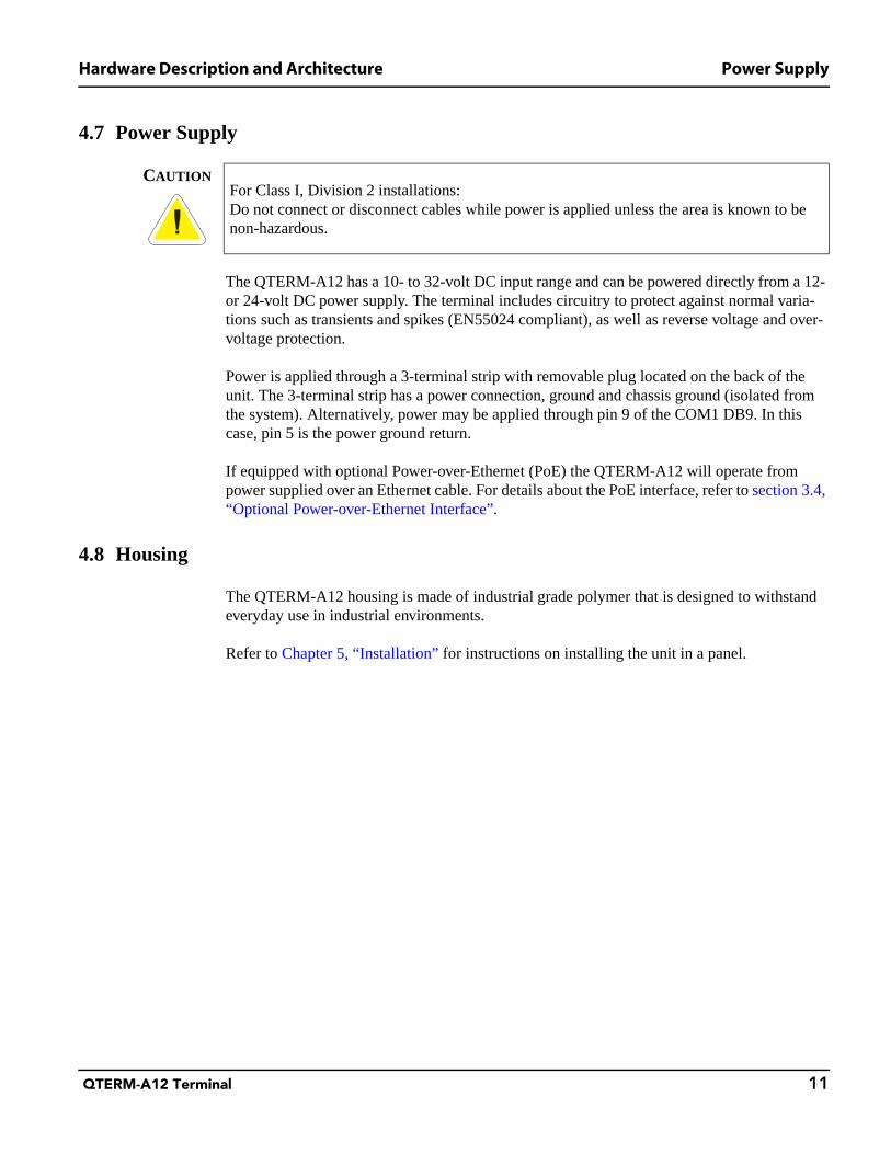
The QTERM-A12 has a 10- to 32-volt DC input range and can be powered directly from a 12- or 24-volt DC power supply. The terminal includes circuitry to protect against normal varia-tions such as transients and spikes (EN55024 compliant), as well as reverse voltage and over-voltage protection.
Power is applied through a 3-terminal strip with removable plug located on the back of the unit. The 3-terminal strip has a power connection, ground and chassis ground (isolated from the system). Alternatively, power may be applied through pin 9 of the COM1 DB9. In this case, pin 5 is the power ground return.
If equipped with optional Power-over-Ethernet (PoE) the QTERM-A12 will operate from power supplied over an Ethernet cable. For details about the PoE interface, refer to section 3.4, “Optional Power-over-Ethernet Interface”.
4.8 Housing
The QTERM-A12 housing is made of industrial grade polymer that is designed to withstand everyday use in industrial environments.
Refer to Chapter 5, “Installation” for instructions on installing the unit in a panel.
CAUTIONFor Class I, Division 2 installations:Do not connect or disconnect cables while power is applied unless the area is known to be non-hazardous.

Housing Hardware Description and Architecture
12 QTERM-A12 Terminal
Notes
QTERM-A12 Terminal 13
CHAPTER 5
INSTALLATION
A QTERM-A12 terminal uses a rugged chemical resistant polymer housing and mounting components. When properly installed in a NEMA-4X rated panel, the QTERM-A12 meets all NEMA-4X specifications including hose-down, icing and salt spray.
A QTERM-A12 terminal can be installed in either a landscape or portrait orientation. In addi-tion, the terminal can be installed with or without a front bezel. The model with factory- installed front bezel is referred to as the standard version and the model without a front bezel is referred to as the modular version.
The standard version of the QTERM-A12 has a factory-installed front bezel. This bezel has molded-in studs that are used in combination with a terminal ring to mount the terminal to the panel.
The modular version of the QTERM-A12 does NOT have a factory-installed front bezel. The modular version of the terminal is ideal for installations that require a custom front bezel or no bezel at all. The modular version requires that the mounting studs be integral with the panel that the terminal will be mounted in.
Take the following steps to install the terminal:
• Decide whether to mount the terminal in portrait or landscape orientation. “Portrait” means that the longest dimension is vertical; “landscape” means that the longest dimension is hori-zontal.
• Cut a hole in the panel or drywall. See section 5.1, “Cutting Out for Panel Mount” for spec-ifications.
• Install the QTERM-A12 terminal in the panel. See section 5.2, “Installing the Terminal” for instructions.
• Connect cables to the terminal. Verify that the thumb screws are tight or the locks snapped into place for each cable used.
• Apply DC power to the QTERM-A12 terminal. See Chapter 3, “Applying Power” for infor-mation.

Cutting Out for Panel Mount Installation
14 QTERM-A12 Terminal
5.1 Cutting Out for Panel Mount
5.1.1 Standard Version Cutout
The standard version cutout is to be used with QTERM-A12 models that have a factory- installed front bezel.
The standard QTERM-A12 terminal can be mounted in panels from 0.8 to 10 mm thick. No screw holes need to be drilled to install the terminal in the panel. Make a rectangular hole in the panel using the following dimensions.
NOTE ☞ See the “QTERM-A12 Cutout and Mounting Guide” insert that was included in the box with the QTERM-A12 for installation instructions. Printed on the back of the insert is a cutout tem-plate that can be used to trace the cutout area onto the housing panel.
Figure 1 is a diagram of the landscape cutout. After the cutout is complete deburr any rough edges prior to mounting the terminal.
Landscape Portrait
Horizontal: 302.5 ± 1 mm Horizontal: 254.0 ± 1 mm
Vertical: 254.0 ± 1 mm Vertical: 302.5 ± 1 mm
Figure 1QTERM-A12 Landscape Cutout (units: mm)

Installation Cutting Out for Panel Mount
QTERM-A12 Terminal 15
5.1.2 Modular Version Cutout
The modular version cutout is to be used with QTERM-A12 models that DO NOT have fac-tory-installed front bezels.
The modular version of the QTERM-A12 terminal can be mounted in panels with any thick-ness. In addition to making a cutout in the panel, the panel must be fitted with mounting studs. Make a rectangular hole in the panel using the following dimensions.
NOTE ☞ See the “QTERM-A12 Cutout and Mounting Guide” insert that was included in the box with the QTERM-A12 for installation instructions. Printed on the back of the insert is a cutout tem-plate that can be used to trace the cutout area onto the housing panel.
Figure 2 is a diagram of the landscape cutout for the modular terminal. After the cutout is com-plete deburr any rough edges prior to mounting the terminal.
Install the recommended studs at the locations shown in Figure 2. The studs must be able to withstand a torque of 67.8 N cm (6 lbs in).
Landscape Portrait
Horizontal: 248.0 ± 1 mm Horizontal: 187.0 ± 1 mm
Vertical: 187.0 ± 1 mm Vertical: 248.0 ± 1 mm
Figure 2Modular QTERM-A12 Landscape Cutout (units: mm)

Installing the Terminal Installation
16 QTERM-A12 Terminal
5.2 Installing the Terminal
NOTE ☞ Use of an anti-static strap is recommended when performing installation and maintenance.
5.2.1 Standard Version Installation
The standard version installation steps are to be used with QTERM-A12 models that have a factory-installed front bezel.
Take the following steps to install the standard terminal.
1. Verify that the panel surface around the cutout is clean and free of rough edges. A gasket built into the terminal seals against the panel surface. Dirt or imperfections on the panel may prevent a proper seal.
2. Place the terminal into the panel cutout and verify that the terminal is oriented correctly. The printed labels on the back panel may indicate the orientation. If not, you can deter-mine which side should be at the top by the position of the serial port(s) on the back panel as follows:
• LandscapeWhen looking at the front of the unit, the back panel serial port(s) should be facing down.
WARNINGWhen mounting the QTERM-A12 terminal within a final enclosure, make sure you provide adequate ventilation: a minimum of 51 mm (2.0 inches) around the back, sides and bottom and 77 mm (3.0 inches) clearance above the top of the QTERM-A12 terminal.
CAUTION
This equipment is suitable for use in Class I, Division 2, Groups A, B, C and D or non-haz-ardous locations only.
CAUTION
EXPLOSION HAZARDSubstitution of components may impair suitability for Class I, Division 2.
CAUTIONFor Class I, Division 2 installations:Do not connect or disconnect cables while power is applied unless the area is known to be non-hazardous.

Installation Installing the Terminal
QTERM-A12 Terminal 17
• PortraitWhen looking at the front of the unit, the back panel serial port(s) should be facing left. Refer to Figure 3 for an example of a landscape installation.
3. On the back of the panel, align the terminal mounting ring holes with the mounting studs, and place the mounting ring against the back of the panel. Refer to Figure 3 for the loca-tion of the mounting studs.
4. Install nuts and washers (supplied with the terminal) onto each of the six mounting studs. Torque all nuts to 67.8 N cm (6 lbs in) to create a seal between the terminal gasket and the panel. Avoid overtightening the nuts.
5.2.2 Modular Version Installation
The modular version installation steps are to be used with QTERM-A12 models that DO NOT have a factory-installed front bezel.
Take the following steps to install the terminal.
1. Verify that the panel surface around the cutout is clean and free of rough edges. A gasket built into the terminal seals against the panel surface. Dirt or imperfections on the panel may prevent a proper seal.
2. Place the terminal over the panel cutout by aligning the terminal mounting holes with the mounting studs of the panel. Ensure that the orientation is correct. The printed labels on
Figure 3QTERM-A12 Mounting

Installing the Terminal Installation
18 QTERM-A12 Terminal
the back panel may indicate the orientation. If not, you can determine which side should be at the top by the position of the serial port(s) on the back panel as follows:
• LandscapeWhen looking at the front of the unit, the back panel serial port(s) should be facing down.
• PortraitWhen looking at the front of the unit, the back panel serial port(s) should be facing left. Refer to Figure 4 for an example of a landscape installation.
3. Install nuts and washers onto each of the six mounting studs. Torque all nuts to 67.8 N cm (6 lbs in) to create a seal between the terminal gasket and the panel. Avoid overtightening the nuts.
Figure 4Modular QTERM-A12 Mounting

QTERM-A12 Terminal 19
CHAPTER 6
SPECIFICATIONS
DISPLAY
ColorTFT color SVGA LCD display65,536 colors
Size308 mm (12.1") diagonal246 mm x 184.5 mm active area
Pixels 800 x 600 (SVGA)
Dot pitch 0.3075 x 0.3075 mm
LightingLED
Brightness is software controllable
Backlight brightness 450 nits typical
Contrast ratio 700:1 (minimum)
TOUCH SCREEN
Analog-resistive operation
5-wire construction
Anti-glare surface treatment with 3H hardness
INTERFACE
Primary serial portUser-configurable EIA-232, EIA-422 or EIA-485 interface with selectable 485 AC terminations and fail-safe network
Secondary serial port EIA-232 serial port with hardware or software flow control
Ethernet 10/100Base-T wired Ethernet with optional PoE
USB host Two USB 2.0 full-speed host ports
Power connector3-pin, 5.0 mm pitch terminal strip. (Phoenix Contact MSTBVA 2,5/3-G – 1755529)
AUDIO
Speaker 0.7 W 8 ohm speaker on back of unit
Specifications
20 QTERM-A12 Terminal
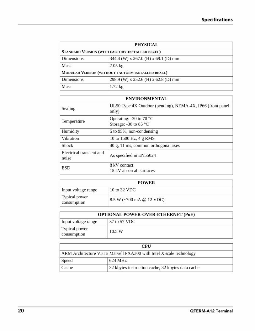
PHYSICAL
STANDARD VERSION (WITH FACTORY-INSTALLED BEZEL)
Dimensions 344.4 (W) x 267.0 (H) x 69.1 (D) mm
Mass 2.05 kg
MODULAR VERSION (WITHOUT FACTORY-INSTALLED BEZEL)
Dimensions 298.9 (W) x 252.6 (H) x 62.8 (D) mm
Mass 1.72 kg
ENVIRONMENTAL
SealingUL50 Type 4X Outdoor (pending), NEMA-4X, IP66 (front panel only)
TemperatureOperating: -30 to 70 °CStorage: -30 to 85 °C
Humidity 5 to 95%, non-condensing
Vibration 10 to 1500 Hz, 4 g RMS
Shock 40 g, 11 ms, common orthogonal axes
Electrical transient and noise
As specified in EN55024
ESD8 kV contact15 kV air on all surfaces
POWER
Input voltage range 10 to 32 VDC
Typical power consumption
8.5 W (~700 mA @ 12 VDC)
OPTIONAL POWER-OVER-ETHERNET (PoE)
Input voltage range 37 to 57 VDC
Typical power consumption
10.5 W
CPU
ARM Architecture V5TE Marvell PXA300 with Intel XScale technology
Speed 624 MHz
Cache 32 kbytes instruction cache, 32 kbytes data cache

Specifications
QTERM-A12 Terminal 21
MEMORY
DDR SDRAM128 Mbytes standard, 16 bit wide bus, 130 Mhz => 520 Mbytes/s transfer rate
Non-volatile storage 4 Gbytes standard
SOFTWARE
Operating system Microsoft Windows Embedded CE version 6.0 R3 Professional
CERTIFICATION
FCC Part 15, Class A
CE Certification EN-55022, EN-55024 and EN-60950
UL Listed by Und. Lab. Inc. To U.S. and Canadian safety standards, UL508 (pending)
Class I, Division 2, Group A, B, C and D hazardous locations, Temperature Code T6 (pend-ing)
RoHS
UL50 Type 4X Outdoor (pending), NEMA-4X, IP66 (front panel only)

Specifications
22 QTERM-A12 Terminal
Notes
QTERM-A12 Terminal 23
CHAPTER 7
MECHANICAL
7.1 Layout and Dimensions
7.1.1 Standard Version
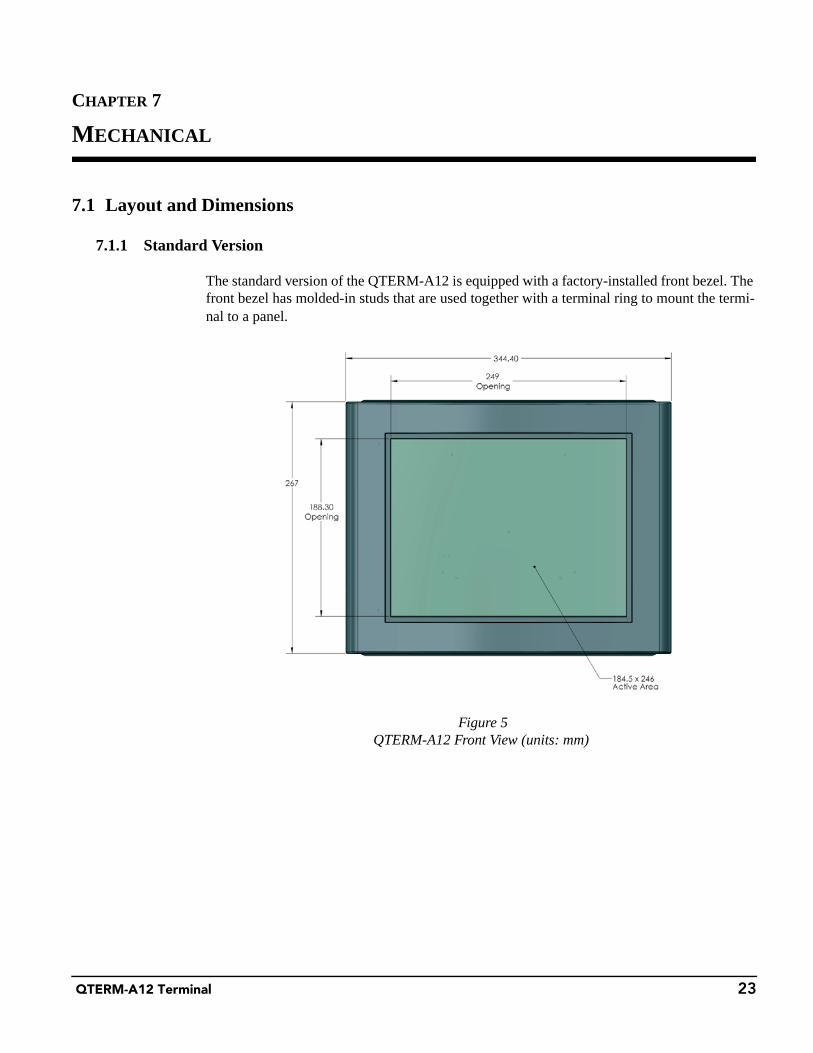
The standard version of the QTERM-A12 is equipped with a factory-installed front bezel. The front bezel has molded-in studs that are used together with a terminal ring to mount the termi-nal to a panel.
Figure 5QTERM-A12 Front View (units: mm)
Layout and Dimensions Mechanical
24 QTERM-A12 Terminal
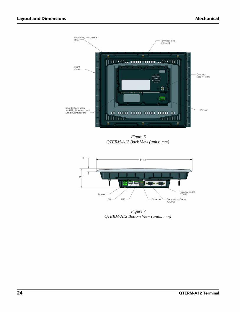
Figure 6QTERM-A12 Back View (units: mm)
Figure 7QTERM-A12 Bottom View (units: mm)

Mechanical Layout and Dimensions
QTERM-A12 Terminal 25
Figure 8QTERM-A12 Side View (units: mm)

Layout and Dimensions Mechanical
26 QTERM-A12 Terminal
7.1.2 Modular Version
The modular version of the QTERM-A12 does NOT have a front bezel. Mounting studs must be integral to the panel where the QTERM-A12 will be mounted. The modular version allows installers to use their own custom bezel or to use the panel as the bezel.
Figure 9Modular QTERM-A12 Front View (units: mm)
Figure 10Modular QTERM-A12 Back View (units: mm)
Mechanical Layout and Dimensions
QTERM-A12 Terminal 27
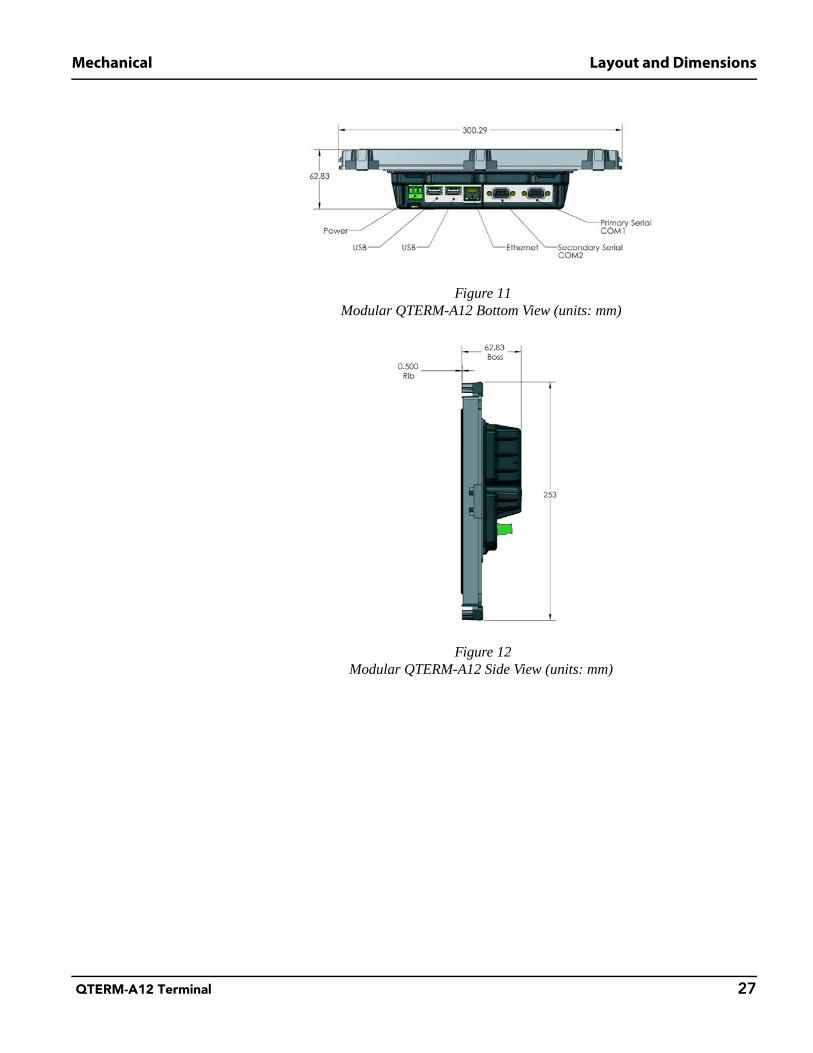
Figure 11Modular QTERM-A12 Bottom View (units: mm)
Figure 12Modular QTERM-A12 Side View (units: mm)
Connector Pinouts Mechanical
28 QTERM-A12 Terminal
7.2 Connector Pinouts
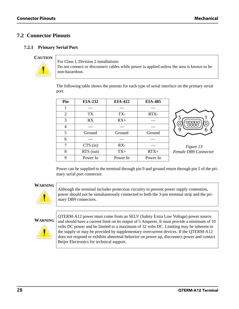
7.2.1 Primary Serial Port
The following table shows the pinouts for each type of serial interface on the primary serial port.
Power can be supplied to the terminal through pin 9 and ground return through pin 5 of the pri-mary serial port connector.
CAUTIONFor Class I, Division 2 installations:Do not connect or disconnect cables while power is applied unless the area is known to be non-hazardous.
Pin EIA-232 EIA-422 EIA-485
1 — — —
Figure 13Female DB9 Connector
2 TX TX- RTX-
3 RX RX+ —
4 — — —
5 Ground Ground Ground
6 — — —
7 CTS (in) RX- —
8 RTS (out) TX+ RTX+
9 Power In Power In Power In
WARNINGAlthough the terminal includes protection circuitry to prevent power supply contention, power should not be simultaneously connected to both the 3-pin terminal strip and the pri-mary DB9 connectors.
WARNINGQTERM-A12 power must come from an SELV (Safety Extra Low Voltage) power source and should have a current limit on its output of 5 Amperes. It must provide a minimum of 10 volts DC power and be limited to a maximum of 32 volts DC. Limiting may be inherent to the supply or may be provided by supplementary overcurrent devices. If the QTERM-A12 does not respond or exhibits abnormal behavior on power up, disconnect power and contact Beijer Electronics for technical support.

Mechanical Connector Pinouts
QTERM-A12 Terminal 29
7.2.2 Secondary Serial Port
The secondary serial port on the QTERM-A12 is configured as EIA-232 only with hardware or software handshaking. The pins are defined below.
7.2.3 Terminal Strip for Power Input
The 3-pin terminal strip is used to provide input voltage and ground to the terminal. The termi-nal strip provides a chassis ground connection. The chassis ground pin is isolated from the sys-tem ground of the terminal.
CAUTIONFor Class I, Division 2 installations:Do not connect or disconnect cables while power is applied unless the area is known to be non-hazardous.
Pinout Table
1 —
Figure 14Female DB9 Connector
2 TX
3 RX
4 —
5 Ground
6 —
7 CTS (in)
8 RTS (out)
9 —
CAUTIONFor Class I, Division 2 installations:Do not connect or disconnect cables while power is applied unless the area is known to be non-hazardous.
Figure 153-Pin Power Connector
Pin Function
1 Power
2 Ground
3 Chassis GND

Connector Pinouts Mechanical
30 QTERM-A12 Terminal
7.2.4 Ethernet Port
The Ethernet port has a standard 10/100Base-T interface with an 8-pin (RJ-45) modular jack connector. The connector orientation and pinout table are shown below. For PoE pinout infor-mation please refer to section 3.4, “Optional Power-over-Ethernet Interface”.
CAUTIONFor Class I, Division 2 installations:Do not connect or disconnect cables while power is applied unless the area is known to be non-hazardous.
Pinout Table1 TX+
Figure 16RJ-45 Connector
2 TX-3 RX+4 —5 —6 RX-7 —
8 —
Mechanical Connector Pinouts
QTERM-A12 Terminal 31
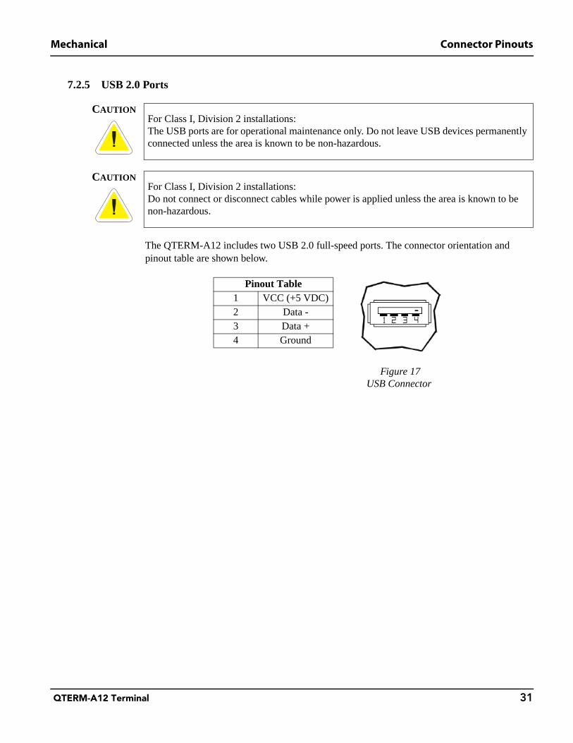
7.2.5 USB 2.0 Ports
The QTERM-A12 includes two USB 2.0 full-speed ports. The connector orientation and pinout table are shown below.
CAUTIONFor Class I, Division 2 installations:The USB ports are for operational maintenance only. Do not leave USB devices permanently connected unless the area is known to be non-hazardous.
CAUTIONFor Class I, Division 2 installations:Do not connect or disconnect cables while power is applied unless the area is known to be non-hazardous.
Pinout Table
Figure 17USB Connector
1 VCC (+5 VDC)2 Data -3 Data +4 Ground

Connector Pinouts Mechanical
32 QTERM-A12 Terminal
Notes