QSC PowerLight 9.0 Service Manual
100
PowerLight™ Series Two-Channel Power Amplifiers TECHNICAL SERVICE MANUAL *TD-000083-00* TD-000083-00 Rev. Prelim. ▲ PowerLight 6.0 II ▲ PowerLight 6.0 PFC ▲ PowerLight 9.0 PFC ON OFF PROTECT STANDBY POWER 1 CHANNEL 2 9000 WATT POWER FACTOR CORRECTED PROFESSIONAL AMPLIFIER 22 22 32 32 24 24 26 26 28 28 30 30 -00 -00 20 20 18 18 14 14 8 8 dB 1 -CHANNEL- 2 dB CLIP -10dB -20dB SIGNAL CLIP LIMITER POWERLIGHT 9.0 PFC HEAR THE POWER OF TECHNOLOGY.
Transcript of QSC PowerLight 9.0 Service Manual
PowerLight™ SeriesTwo-Channel Power Amplifiers
TECHNICAL SERVICE MANUAL
*TD-000083-00*TD-000083-00
Rev. Prelim.
PowerLight 6.0 II
PowerLight 6.0PFC
PowerLight 9.0PFC
ON
OFF
P R O T E C T
S TA N D B Y
P O W E R
1 C H A N N E L 29 0 0 0 W AT T P O W E R F A C T O R C O R R E C T E D P R O F E S S I O N A L A M P L I F I E R
22 22
32 32
24 24
26 26
28 28
30 30
-00 -00
20 20
18 18
14 14
8 8
dB
1 - C H A N N E L - 2
dB
C L I P
- 10 d B
- 2 0 d B
S I G N A L
C L I P L I M I T E RPOWERLIGHT 9.0PFC
HEAR THE POWER OF TECHNOLOGY.

Technical Service Manual 1PowerLight 6.0 II, PowerLight 6.0PFC, and PowerLight 9.0PFC
QSC Audio Products, Inc.
Technical Services GroupPhone: 1-800 QSC AUDIO (1-800-772-2834) USA only
+1 (714) 957-7150Fax: +1 (714) 754-6173Postal: 1665 MacArthur Blvd.
Costa Mesa, California 92626 USAE-mail: [email protected]: http://www.qscaudio.com (product information and support)
http://www.qscstore.com (parts and accessory sales)
PowerLight SeriesTechnical Service Manual
Copyright 2004 QSC Audio Products, Inc. All rights reserved.
Document # TD-000083-00, Preliminary Rev. Released November 2004.
IMPORTANT NOTICE:
This document contains proprietary information that is the propertyof QSC Audio Products, Inc, and may not be disclosed, reproduced orused without express or written consent from QSC Audio Products.
PowerLight 6.0 II
PowerLight 6.0PFC
PowerLight 9.0PFC

2 QSC Audio Products, Inc.TD-000083-00
PowerLight 9.0PFC
PowerLight 6.0PFC
PowerLight 9.0 II
Technical Service Manual 3PowerLight 6.0 II, PowerLight 6.0PFC, and PowerLight 9.0PFC
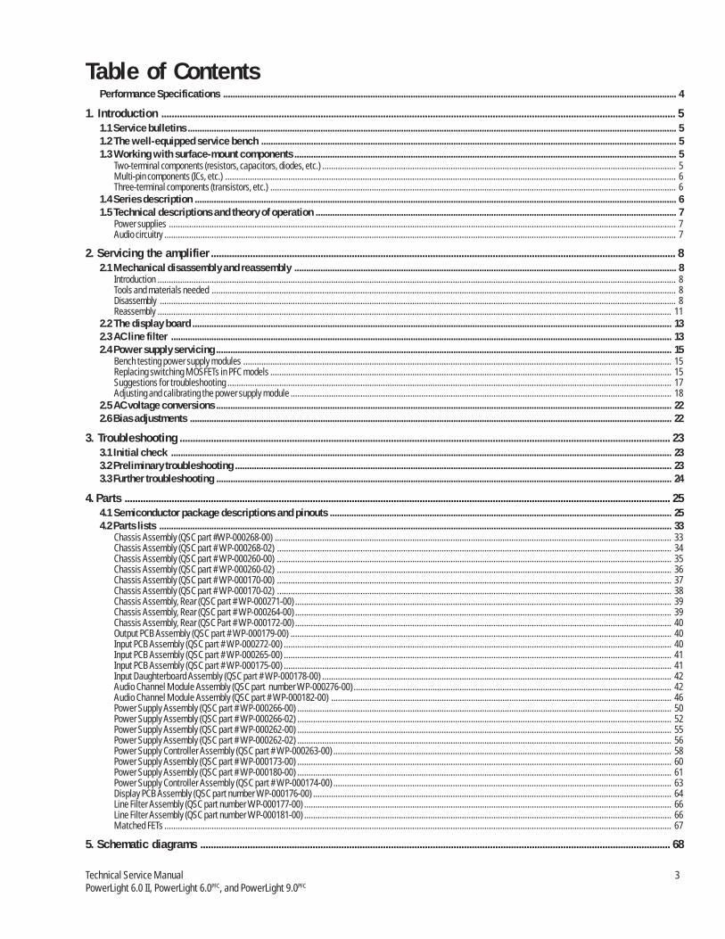
Table of ContentsPerformance Specifications ............................................................................................................................................................................................... 4
1. Introduction ..................................................................................................................................................................................................... 51.1 Service bulletins .............................................................................................................................................................................................................. 51.2 The well-equipped service bench ............................................................................................................................................................................... 51.3 Working with surface-mount components ................................................................................................................................................................. 5
Two-terminal components (resistors, capacitors, diodes, etc.) ............................................................................................................................................................. 5Multi-pin components (ICs, etc.) ........................................................................................................................................................................................................ 6Three-terminal components (transistors, etc.) .................................................................................................................................................................................... 6
1.4 Series description ........................................................................................................................................................................................................... 61.5 Technical descriptions and theory of operation ........................................................................................................................................................ 7
Power supplies ................................................................................................................................................................................................................................. 7Audio circuitry ................................................................................................................................................................................................................................... 7
2. Servicing the amplifier .................................................................................................................................................................................. 82.1 Mechanical disassembly and reassembly ................................................................................................................................................................. 8
Introduction ...................................................................................................................................................................................................................................... 8Tools and materials needed .............................................................................................................................................................................................................. 8Disassembly ..................................................................................................................................................................................................................................... 8Reassembly .................................................................................................................................................................................................................................... 11
2.2 The display board .......................................................................................................................................................................................................... 132.3 AC line filter ................................................................................................................................................................................................................... 132.4 Power supply servicing ................................................................................................................................................................................................ 15
Bench testing power supply modules .............................................................................................................................................................................................. 15Replacing switching MOSFETs in PFC models .................................................................................................................................................................................. 15Suggestions for troubleshooting ..................................................................................................................................................................................................... 17Adjusting and calibrating the power supply module ......................................................................................................................................................................... 18
2.5 AC voltage conversions ................................................................................................................................................................................................ 222.6 Bias adjustments ........................................................................................................................................................................................................... 22
3. Troubleshooting ............................................................................................................................................................................................ 233.1 Initial check ................................................................................................................................................................................................................... 233.2 Preliminary troubleshooting ........................................................................................................................................................................................ 233.3 Further troubleshooting ................................................................................................................................................................................................ 24
4. Parts ................................................................................................................................................................................................................. 254.1 Semiconductor package descriptions and pinouts ................................................................................................................................................ 254.2 Parts lists ........................................................................................................................................................................................................................ 33
Chassis Assembly (QSC part #WP-000268-00) ................................................................................................................................................................................ 33Chassis Assembly (QSC part # WP-000268-02) ............................................................................................................................................................................... 34Chassis Assembly (QSC part # WP-000260-00) ............................................................................................................................................................................... 35Chassis Assembly (QSC part # WP-000260-02) ............................................................................................................................................................................... 36Chassis Assembly (QSC part # WP-000170-00) ............................................................................................................................................................................... 37Chassis Assembly (QSC part # WP-000170-02) ............................................................................................................................................................................... 38Chassis Assembly, Rear (QSC part # WP-000271-00) ....................................................................................................................................................................... 39Chassis Assembly, Rear (QSC part # WP-000264-00) ....................................................................................................................................................................... 39Chassis Assembly, Rear (QSC Part # WP-000172-00) ....................................................................................................................................................................... 40Output PCB Assembly (QSC part # WP-000179-00) ......................................................................................................................................................................... 40Input PCB Assembly (QSC part # WP-000272-00) ............................................................................................................................................................................ 40Input PCB Assembly (QSC part # WP-000265-00) ............................................................................................................................................................................ 41Input PCB Assembly (QSC part # WP-000175-00) ............................................................................................................................................................................ 41Input Daughterboard Assembly (QSC part # WP-000178-00) ........................................................................................................................................................... 42Audio Channel Module Assembly (QSC part number WP-000276-00) ............................................................................................................................................. 42Audio Channel Module Assembly (QSC part # WP-000182-00) ....................................................................................................................................................... 46Power Supply Assembly (QSC part # WP-000266-00) ...................................................................................................................................................................... 50Power Supply Assembly (QSC part # WP-000266-02) ...................................................................................................................................................................... 52Power Supply Assembly (QSC part # WP-000262-00) ...................................................................................................................................................................... 55Power Supply Assembly (QSC part # WP-000262-02) ...................................................................................................................................................................... 56Power Supply Controller Assembly (QSC part # WP-000263-00) ...................................................................................................................................................... 58Power Supply Assembly (QSC part # WP-000173-00) ...................................................................................................................................................................... 60Power Supply Assembly (QSC part # WP-000180-00) ...................................................................................................................................................................... 61Power Supply Controller Assembly (QSC part # WP-000174-00) ...................................................................................................................................................... 63Display PCB Assembly (QSC part number WP-000176-00) ............................................................................................................................................................... 64Line Filter Assembly (QSC part number WP-000177-00) ................................................................................................................................................................... 66Line Filter Assembly (QSC part number WP-000181-00) ................................................................................................................................................................... 66Matched FETs ................................................................................................................................................................................................................................. 67
5. Schematic diagrams .................................................................................................................................................................................... 68
4 QSC Audio Products, Inc.TD-000083-00
PowerLight 6.0 II PowerLight 6.0PFC PowerLight 9.0PFC
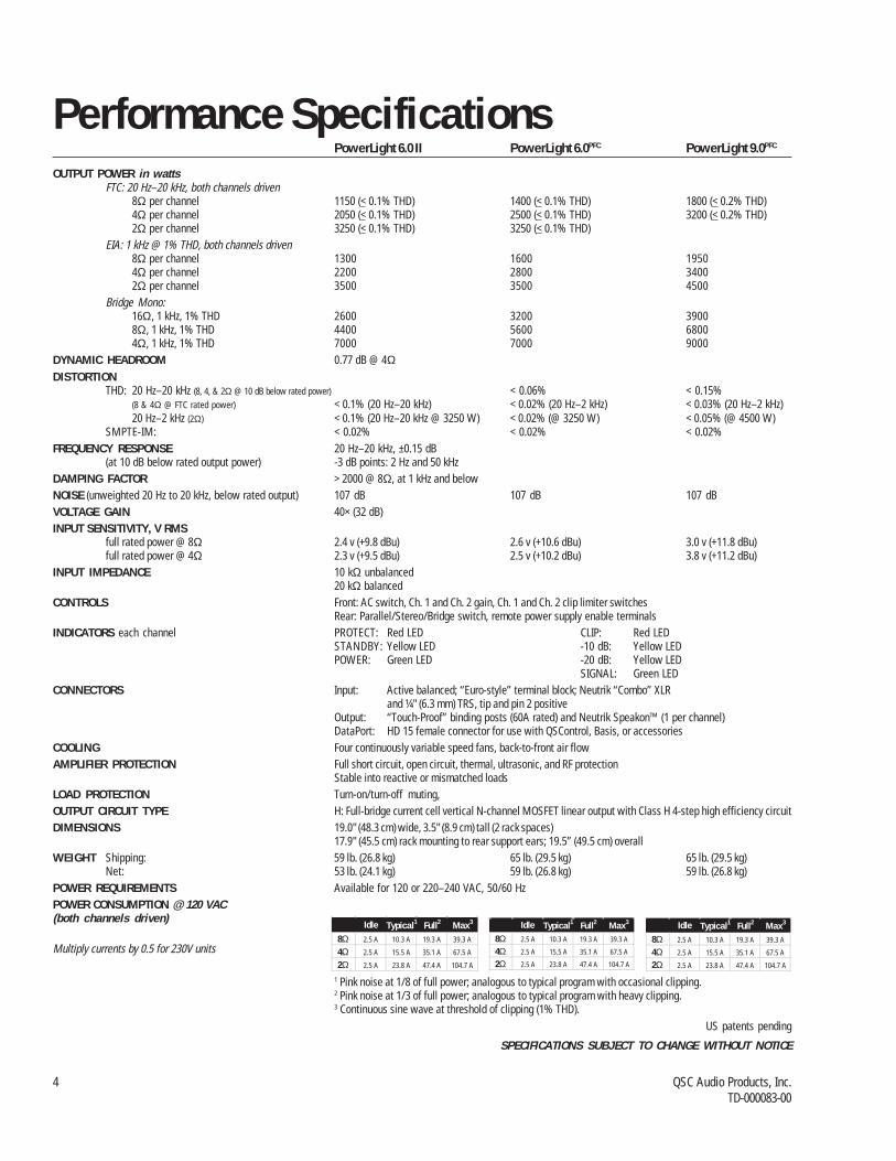
OUTPUT POWER in wattsFTC: 20 Hz–20 kHz, both channels driven
8Ω per channel 1150 (< 0.1% THD) 1400 (< 0.1% THD) 1800 (< 0.2% THD)4Ω per channel 2050 (< 0.1% THD) 2500 (< 0.1% THD) 3200 (< 0.2% THD)2Ω per channel 3250 (< 0.1% THD) 3250 (< 0.1% THD)
EIA: 1 kHz @ 1% THD, both channels driven8Ω per channel 1300 1600 19504Ω per channel 2200 2800 34002Ω per channel 3500 3500 4500
Bridge Mono:16Ω, 1 kHz, 1% THD 2600 3200 39008Ω, 1 kHz, 1% THD 4400 5600 68004Ω, 1 kHz, 1% THD 7000 7000 9000
DYNAMIC HEADROOM 0.77 dB @ 4ΩDISTORTION
THD: 20 Hz–20 kHz (8, 4, & 2Ω @ 10 dB below rated power) < 0.06% < 0.15%(8 & 4Ω @ FTC rated power) < 0.1% (20 Hz–20 kHz) < 0.02% (20 Hz–2 kHz) < 0.03% (20 Hz–2 kHz)20 Hz–2 kHz (2Ω) < 0.1% (20 Hz–20 kHz @ 3250 W) < 0.02% (@ 3250 W) < 0.05% (@ 4500 W)
SMPTE-IM: < 0.02% < 0.02% < 0.02%FREQUENCY RESPONSE 20 Hz–20 kHz, ±0.15 dB
(at 10 dB below rated output power) -3 dB points: 2 Hz and 50 kHzDAMPING FACTOR > 2000 @ 8Ω, at 1 kHz and belowNOISE (unweighted 20 Hz to 20 kHz, below rated output) 107 dB 107 dB 107 dBVOLTAGE GAIN 40× (32 dB)INPUT SENSITIVITY, V RMS
full rated power @ 8Ω 2.4 v (+9.8 dBu) 2.6 v (+10.6 dBu) 3.0 v (+11.8 dBu)full rated power @ 4Ω 2.3 v (+9.5 dBu) 2.5 v (+10.2 dBu) 3.8 v (+11.2 dBu)
INPUT IMPEDANCE 10 kΩ unbalanced20 kΩ balanced
CONTROLS Front: AC switch, Ch. 1 and Ch. 2 gain, Ch. 1 and Ch. 2 clip limiter switchesRear: Parallel/Stereo/Bridge switch, remote power supply enable terminals
INDICATORS each channel PROTECT: Red LED CLIP: Red LEDSTANDBY: Yellow LED -10 dB: Yellow LEDPOWER: Green LED -20 dB: Yellow LED
SIGNAL: Green LEDCONNECTORS Input: Active balanced; “Euro-style” terminal block; Neutrik “Combo” XLR
and ¼" (6.3 mm) TRS, tip and pin 2 positiveOutput: “Touch-Proof” binding posts (60A rated) and Neutrik Speakon™ (1 per channel)DataPort: HD 15 female connector for use with QSControl, Basis, or accessories
COOLING Four continuously variable speed fans, back-to-front air flowAMPLIFIER PROTECTION Full short circuit, open circuit, thermal, ultrasonic, and RF protection
Stable into reactive or mismatched loadsLOAD PROTECTION Turn-on/turn-off muting,OUTPUT CIRCUIT TYPE H: Full-bridge current cell vertical N-channel MOSFET linear output with Class H 4-step high efficiency circuitDIMENSIONS 19.0" (48.3 cm) wide, 3.5" (8.9 cm) tall (2 rack spaces)
17.9" (45.5 cm) rack mounting to rear support ears; 19.5” (49.5 cm) overallWEIGHT Shipping: 59 lb. (26.8 kg) 65 lb. (29.5 kg) 65 lb. (29.5 kg)
Net: 53 lb. (24.1 kg) 59 lb. (26.8 kg) 59 lb. (26.8 kg)POWER REQUIREMENTS Available for 120 or 220–240 VAC, 50/60 HzPOWER CONSUMPTION @ 120 VAC(both channels driven)
Multiply currents by 0.5 for 230V units
1 Pink noise at 1/8 of full power; analogous to typical program with occasional clipping.2 Pink noise at 1/3 of full power; analogous to typical program with heavy clipping.3 Continuous sine wave at threshold of clipping (1% THD).
US patents pending
SPECIFICATIONS SUBJECT TO CHANGE WITHOUT NOTICE
Performance Specifications
Idle Typical1 Full2 Max3
8Ω 2.5 A 10.3 A 19.3 A 39.3 A
4Ω 2.5 A 15.5 A 35.1 A 67.5 A
2Ω 2.5 A 23.8 A 47.4 A 104.7 A
Idle Typical1 Full2 Max3
8Ω 2.5 A 10.3 A 19.3 A 39.3 A
4Ω 2.5 A 15.5 A 35.1 A 67.5 A
2Ω 2.5 A 23.8 A 47.4 A 104.7 A
Idle Typical1 Full2 Max3
8Ω 2.5 A 10.3 A 19.3 A 39.3 A
4Ω 2.5 A 15.5 A 35.1 A 67.5 A
2Ω 2.5 A 23.8 A 47.4 A 104.7 A

Technical Service Manual 5PowerLight 6.0 II, PowerLight 6.0PFC, and PowerLight 9.0PFC
Solder braid
1. Introduction1.3 Working with surface-mountcomponentsPowerLight amplifiers, like many modern electronic products, usesurface-mount technology (SMT) components where appropriate inorder to make high-density circuitry that is reliable and economicalto manufacture.
SMT components in the PowerLight amps are used in the small-signal and control circuits, so they do not handle significantamounts of power; therefore, they are subject to very little stressand should seldom fail. Sometimes they do fail, or they requirereplacement for a performance upgrade or modification. Thus, it isimportant to know how to work with SMT components.
Specialized tools and equipment exist for soldering, unsoldering,and removing SMT components quickly and efficiently, but they areoften expensive. Most SMT repairs, though, can be handled reason-ably well with common tools and equipment, such as tweezers,solder braid, and fine-tip soldering irons.
Two-terminal components (resistors, capacitors,diodes, etc.)Removal1. Use two soldering irons, prefer-
ably about 25 to 40 watts, withfine tips.
2. With a soldering iron in eachhand, hold one tip on the solder atone end of the component and theother tip on the other end (Figure1.1).
3. Once the solder melts on bothends, grip the componentbetween the two tips and lift itfrom the circuit board.
4. Use solder braid and a solderingiron to remove the solder from thetwo pads (Figure 1.2).
Insertion1. With a soldering iron and 60/40 or 63/37 eutectic-type solder,
melt just enough solder onto one pad to create a small mound(Figure 1.3).
2. Grasp the component in the middle with tweezers. Melt thesmall mound of solder with the iron and place the componentacross the two pads (in the correct orientation, if the compo-nent is sensitive to direction) and press it flat against the circuitboard, with one end of the component immersed in the meltedsolder (Figure 1.4).
3. Hold the component in place and take the soldering iron away.
1.1 Service bulletinsContact QSC Technical Services to make sure you have the mostup-to-date service bulletins for PowerLight Series amplifiers.Service bulletins may be distributed in hard copy, via fax, andelectronically (Adobe Acrobat PDF) via CD-ROMs, FTP from the QSCweb site (www.qscaudio.com), and e-mail.
These service bulletins had been issued at the time this manualwas printed: PFC0001, “PFC MOSFET Replacement” (PowerLight6.0PFC and PowerLight 9.0PFC only); PFC0002, “PFC Power SupplyReplacement Guidelines” (PowerLight 6.0PFC and PowerLight 9.0PFC
only); and PFC0003, “Amplifier Goes Into Protect When Turned On”(all three models).
1.2 The well-equipped servicebenchTo properly service QSC amplifiers, a technician needs the righttools. The technician’s service bench should have the followingequipment:• Digital multimeter with RMS AC voltage and current• Digital clamp-on ammeter• Dual-trace oscilloscope• Audio distortion analyzer• Non-inductive load resistors, configurable as 8 ohms (min. 1800
watts capacity), as 4 ohms (min. 3200 watts capacity), and as2 ohms (min. 4500 watts capacity)
• Variable AC voltage source, such as a Variac or Powerstatvariable transformer, with a rated current capacity of up to 50A(for 120V models) or 25A (for 230V models)
• Low-distortion audio sine wave generator• Philips and flat screwdrivers• Soldering iron with a fine tip (25–60W recommended)• Rosin-core solder (60/40 or 63/37)• Long-nose pliers• Diagonal cutters• Wire strippersAutomated test equipment, such as an Audio Precision worksta-tion, is very useful for servicing PowerLight amplifiers. ContactQSC Technical Services to obtain applicable AP test files.
Servicing power supply modules will require some additionalspecial-built equipment:• Power supply remote controller• PFC power supply fixture (for PFC modules only)• CMP boxBecauseof the complexity of the PFC power supplies, QSCrecommends they be serviced only by QSC.
Figure 1.1.
Figure 1.2.

6 QSC Audio Products, Inc.TD-000083-00
Solder
Solder
Tweezers
Solder
Let the solder harden to tack thecomponent in place.
4. Fully solder the other end of thecomponent to its pad. Let thesolder harden (Figure 1.5).
5. Fully solder the tacked end ofthe component to its pad (Figure1.6).
Three-terminalcomponents (transistors,etc.)Removal1. With a soldering iron and solder
braid, remove as much solder aspossible from the middleterminal of the component.
2. With a soldering iron in eachhand, hold one tip on the solderat the terminal at one end of thecomponent and the other tip onthe terminal at the other end.
3. When the solder on both ends
melts, grip the component between the two tips and lift it fromthe circuit board. You might need to quickly touch the pad onthe middle terminal with a soldering iron to melt any remainingsolder that might be holding the component down.
4. Use solder braid and a soldering iron to remove the solder fromthe three pads.
Insertion1. With a soldering iron and 60/40 or 63/37 eutectic-type solder,
melt just enough solder onto one pad to create a small moundof solder.
2. Grasp the component with tweezers. Melt the small mound ofsolder with the iron and place the component in the correctorientation across the three pads and press it flat against thecircuit board, with one terminal of the component pressed intothe melted solder.
3. Hold the component in place and take the soldering iron away.Let the solder harden to tack the component in place.
4. Fully solder the other terminals of the component to their pads.Let the solder harden.
5. Fully solder the tacked terminal of the component to its pad.
Multi-pin components (ICs, etc.)Removal
Removing a multi-pin SMT component is a delicate procedure.Ideally, you should use a soldering iron with an attachment thatallows you to heat all the pins simultaneously.
If such a soldering device is not available, use this procedure:1. Use a soldering iron and solder braid to remove as much solder
as possible from the pins of the component.
2. With fine tweezers, carefully try to lift each pin to see if it’sfree. If it’s not, touch it with the tip of the soldering iron and ifnecessary, use the solder braid to remove the remaining solder.
3. Repeat the process until all the pins are free and you canremove the component.
Insertion1. With a soldering iron and 60/40 or 63/37 eutectic-type solder,
melt just enough solder onto one pad to create a small moundof solder. It is usually easiest to use a pad that corresponds toone of the end or corner pins of the component.
2. Grasp the component with tweezers. Melt the small mound ofsolder with the iron and place the component in the correctorientation upon its pads and gently press it flat against thecircuit board, with the appropriate terminal of the componentpressed into the melted solder.
3. Hold the component in place and take the soldering iron away.Let the solder harden to tack the component in place.
4. Fully solder the other terminals of the component to their pads.Let the solder harden.
5. Fully solder the tacked terminal of the component to its pad.
1.4 Series descriptionQSC’s PowerLight Series amplifiers are high-performanceprofessional audio products, designed primarily for live and touringsound and large-scale installations.
This service manual covers the three most powerful modelsdeveloped for the PowerLight Series: the PowerLight 6.0 II, thePowerLight 6.0PFC, and the PowerLight 9.0PFC. Each one has twoaudio channels and is three rack spaces tall. See page 2 forcomplete specifications.
The PowerLight 6.0PFC and PowerLight 9.0PFC feature powersupplies with power factor correction, which reduces peak currentdemand by drawing power throughout the AC voltage waveform.The PowerLight 6.0 II has power supplies that don’t have PFC butare simpler and less expensive to manufacture.
The first four digits of the amplifier’s serial number indicate themonth and year of manufacture in MMYY formay. For example,0701xxxxx = July 2001). A serial number that starts with “13”indicates the amplifier was made during the model’s betaproduction. The PowerLight 9.0PFC entered production in May 1998.The PowerLight 6.0PFC followed in March 1999, and thePowerLight 6.0 II, in August 2002. Many PowerLight 6.0PFC
amplifiers, however, have been converted by QSC TechnicalServices into PowerLight 6.0 II amplifiers, so you may encounterPowerLight 6.0 II amplifiers with serial number date codes thatprecede the model’s actual release date.
The PowerLight 6.0PFC and PowerLight 9.0PFC ceased production inMarch 2004.
Figure 1.3.
Figure 1.4.
Figure 1.5.
Figure 1.6.

Technical Service Manual 7PowerLight 6.0 II, PowerLight 6.0PFC, and PowerLight 9.0PFC
1.5 Technical descriptions andtheory of operationPower suppliesQSC PowerLight amplifiers feature high-frequency switch-modepower supplies that help reduce noise, increase electricalefficiency, and lower weight. Two models, the PowerLight 9.0PFC
and the PowerLight 6.0PFC, had power factor correction to reducethe peak current demand fromthe AC mains. They accom-plished this by drawing currentthroughout the AC voltagewaveform, instead of just atthe peaks, as most amplifiersand other electronic equipmentdo. The PowerLight 6.0 II wasdeveloped later, and its powersupplies do not have powerfactor correction.
All three models have a four-tier class H system of multiplerail voltages to boost efficiency.A power amplifier is most efficient at or near full power, yet thedynamic nature of music and other typical audio requires much lessthan full power most of the time. Thus, this class H scheme createsessentially four different “full-power” levels within the amplifier
channel. The amplifier circuitryautomatically and instanta-neously switches to the lowestrail voltage that will allow thereproduction of the audiosignal without discontinuity.
Each amplifier channel has itsown power supply. In addition,each has a small “housekeep-ing” supply that manages theturn-on functions before themain power supply starts up.
Audio circuitryThe audio inputs are balanced to offer a high amount of common-mode noise rejection. The input balancing is done using aninstrumentation amplifier arrangement, which uses a single opamp, arranged as a voltage follower or buffer, on each leg of thebalanced input, driving a single op amp differential amplifier. Thedegree of common-mode rejection is dependent on the closematching of the impedance between each leg and ground andaround the differential amplifier. The circuitry uses 1% precisionresistors to ensure at least 40 dB of common-mode rejection.
The differential amplifier circuitry includes a first-order high-frequency roll-off, down 3 dB at 280 kHz (nearly four octaves abovethe high end of the audio spectrum). This makes the amplifier less
susceptible to RF interference,high-frequency oscillations, etc.
The audio signal passes througha pre-clipper, which preventsthe audio signal from drivingthe output section itself intoactual clipping. This maintainsdamping on the channel outputeven during clipping so that itcontinues to tightly control theloudspeaker motion, which issomething most amplifierscannot do. A defeatable cliplimiter on each channel reducessignal level when clipping occurs; it does not prevent clipping, butreduces the amount of distortion to inaudible or barely audiblelevels.
An all-pass filter uses group delay to slow the audio signal by 4 µs,but the class H steps are controlled by the undelayed signal. Thisreduces IM distortion by ensuring that the steps are executedbefore the audio signal in the output section reaches the transitionthresholds.
The audio signal voltage is converted into current by transistorsQ87 and Q89, to be precisely bifurcated into positive and negativehalves by the current steering circuitry. These current signals arethe controls for the output devices.
The output devices are verticalMOSFETs, which are commonlyused for very high powerswitching because of theirpower handling capability andgeneral nonlinearity. Usingthem for linear audio amplifica-tion requires an unorthodoxapproach. In these threePowerLight amplifier models,each channel has eight MOSFETdevices arranged in a full bridgeconfiguration. Each one has a
local management circuit calleda current cell that controls andlinearizes the device byproviding the necessarycompensation to make theMOSFET’s conductivity track thesignal current.
Figure 1.7. Amplifiers withoutPFC draw current only at thepeaks of the AC voltagewaveform.
Figure 1.8. An amplifier with PFCdraws current throughout theAC voltage waveform.
Figure 1.10. Most amps losefeedback during clipping,resulting in loss of damping andin “clip sticking.”
Figure 1.9. The rail voltages ofthe output section switchamong four tiers to reproducethe signal faithfully whilemaximizing efficiency.
Figure 1.11. The pre-clippingscheme in the PowerLight 6.0PFC,9.0PFC, and 6.0 II keeps theoutput signal clean despite theflat-topping of the waveform.

8 QSC Audio Products, Inc.TD-000083-00
2. Servicing the amplifier2.1 Mechanical disassembly and reassembly
Key QSC Part Description Qty.12345
WP-000170-XX Chassis assy., PL 9.0 1CH-000079-00 Top cover 1SC-082051-PL Screw, #8-32 × 5/16”, pan head 6SC-080051-PU Screw, #8-32 × 5/16”, flat head 12PL-000104-00 Insulator, high volt. 2
IntroductionReplacing components will usually require removing the affectedmodules from the amplifier chassis. The two channels each havetheir own power supply module and audio module, and they sharethe line filter assembly and the input, output, and display boardassemblies.
Within the chassis, the power supply modules are on the bottom,and the audio modules are on top. Getting at a power supplymodule requires removal of its audio module first.
The following instructions describe the procedure for removingboth audio and both power supply modules. However, if you onlyneed to work on one channel, you do not need to remove themodules from the other.
Tools and materials needed• Philips screwdriver• Diagonal cutters• Tie wraps• Needle-nose pliers• Adhesive rubber foot (one per channel), QSC part # QQ-
QQQQQQ-QQ or equivalent• 5/64” hex (Allen) key• 11/32” nutdriver or socket wrench• Isopropyl alcohol and a small brush
DisassemblyRemoving the top cover1. Disconnect the amplifier from AC power and allow at least 10
minutes for internal voltages to bleed down.
2. A total of 18 screws—six with pan heads and twelve with flatheads—hold the top cover to the chassis. Using a Philipsscrewdriver, remove them and set them aside. See Figure 2.1.
3. Lift the top cover up at the front until it clears the side rack earpieces, then lift it off the chassis. If the front of the cover isbent or dented, make sure the front edge clears the twodisplay board headers.
Figure 2.1. Removing or installingthe top cover.
Technical Service Manual 9PowerLight 6.0 II, PowerLight 6.0PFC, and PowerLight 9.0PFC
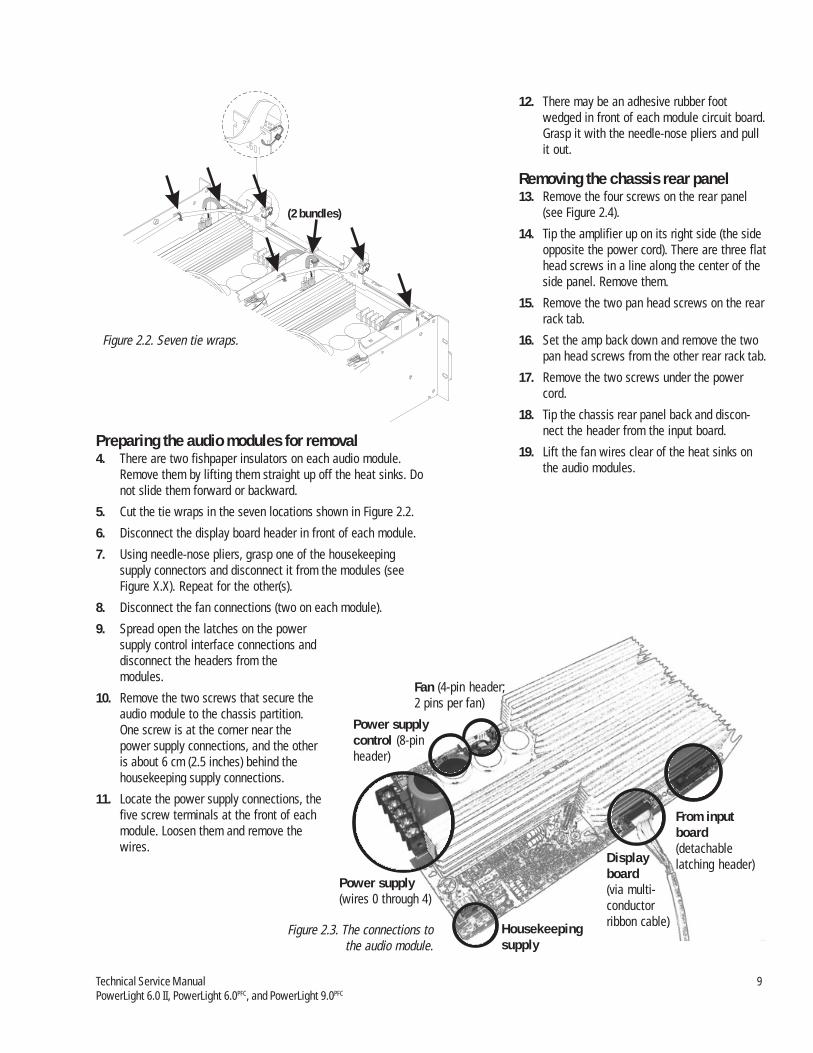
Fan (4-pin header;2 pins per fan)
Power supply(wires 0 through 4)
Housekeepingsupply
Displayboard(via multi-conductorribbon cable)
From inputboard(detachablelatching header)
(2 bundles)
Preparing the audio modules for removal4. There are two fishpaper insulators on each audio module.
Remove them by lifting them straight up off the heat sinks. Donot slide them forward or backward.
5. Cut the tie wraps in the seven locations shown in Figure 2.2.
6. Disconnect the display board header in front of each module.
7. Using needle-nose pliers, grasp one of the housekeepingsupply connectors and disconnect it from the modules (seeFigure X.X). Repeat for the other(s).
8. Disconnect the fan connections (two on each module).
9. Spread open the latches on the powersupply control interface connections anddisconnect the headers from themodules.
10. Remove the two screws that secure theaudio module to the chassis partition.One screw is at the corner near thepower supply connections, and the otheris about 6 cm (2.5 inches) behind thehousekeeping supply connections.
11. Locate the power supply connections, thefive screw terminals at the front of eachmodule. Loosen them and remove thewires.
12. There may be an adhesive rubber footwedged in front of each module circuit board.Grasp it with the needle-nose pliers and pullit out.
Removing the chassis rear panel13. Remove the four screws on the rear panel
(see Figure 2.4).
14. Tip the amplifier up on its right side (the sideopposite the power cord). There are three flathead screws in a line along the center of theside panel. Remove them.
15. Remove the two pan head screws on the rearrack tab.
16. Set the amp back down and remove the twopan head screws from the other rear rack tab.
17. Remove the two screws under the powercord.
18. Tip the chassis rear panel back and discon-nect the header from the input board.
19. Lift the fan wires clear of the heat sinks onthe audio modules.
Power supplycontrol (8-pinheader)
Figure 2.2. Seven tie wraps.
Figure 2.3. The connections tothe audio module.

10 QSC Audio Products, Inc.TD-000083-00
Key QSC Part Description Qty.12345
CH-000078-00 Chassis, PL 9.0 1WP-000172-00 Rear chassis assembly 1SC-082051-PL Screw, #8 × 5/16”, pan head 4SC-080051-PU Screw, #8-32 × 5/16”, flat head 4SC-082051-PL Screw, #8 × 5/16”, pan head 2
20. Remove the chassis rear panel from the main chassis.
21. Cut and remove the tie wraps that secure the output wires tothe rear panel.
Removing the audio modules22. There is a ground screw at the back of each audio module
(see Figure 2.4). Remove it.
23. Slide the audio module toward the front of the chassis so thatits keyed mounting holes are clear of the standoffs.
24. Lift up the back of the audio module slightly, then lift theentire module clear of the chassis.
Removing the power supply modules25. If you need to remove one or both power supply modules, you
will need to remove both audio modules. Invert one audiomodule and set it on top of the other channel’s audio module,then set them aside.
26. Straighten the five power supply wires on each channel.
27. Remove the three screws from the front of the chassispartition.
28. Remove the side-facing screw from the front of the partitionon channel 1’s side.
29. Remove two black pan head screws from the center line ofthe chassis partition.
30. Slide the chassis partition back, then lift up on the channel 2side of it. Press down on the back of the partition, then lift itclear of the chassis.
31. Remove the two screws at the front of the power supplymodule.
32. Use a 5/64” hex (Allen) key to remove the screw at the rear ofthe power supply module.
33. Use an 11/32” nutdriver or socket wrench to remove the twonuts on the AC connection (a white and a black wire).
34. Slide the power supply module toward the rear of the chassis,then lift it up and out of the amplifier.
Inspecting the power supply modules35. Visually inspect the power supply module. Check the leads of
diodes D1 and D12, because they sometimes crack due toflexing of the circuit board.
36. Using isopropyl alcohol and a brush, clean any dirty or charredparts of the circuit board. Look for burned-off circuit boardtraces, especially around the switching MOSFETs; missing ordamaged ones can be repaired using a trace repair kit. If the
Locations ofground screwsfor audio modules
Figure 2.4. Removing or installing thechassis rear panel.

Technical Service Manual 11PowerLight 6.0 II, PowerLight 6.0PFC, and PowerLight 9.0PFC
Key QSC Part Description Qty.12345
8
CH-000078-00 Chassis, PL 9.0 1PL-000107-00 Heatsink insulator 2CH-000080-00 Chassis horiz. partition 1SC-080051-PS Screw, #8-32 × 5/16”, SEMS 3
PL-000109-00 Insulator, mega platform 2PL-000137-00 2
67
SC-082051-PU Screw, #8-32 × 5/16”, pan head 3SC-060042-PP Screw, #6-32 × 1/4”, SEMS 3
Insulator, amp rear bottom
circuit board is burned into the fiber layers or badly damaged,replace the entire module.
See instructions for servicing the power supply moduleelsewhere in this chapter.
ReassemblyReassembling the amplifier chassis is essentially reversing theorder of the disassembly process.
Installing the power supply module1. Align the keyed slots in the power supply module circuit board
with the chassis standoffs. Watch out for the fish paperinsulators, which may get caught underneath. Drop themodule into place on the standoffs and slide it forward.
2. Using the 11/32” nutdriver or socket wrench, attach the ACwires to the module. The black wire attaches in front (closerto the front of the amplifier chassis) of the white one.
3. Using the 5/64” hex (Allen) key, insert and tighten the screwat the rear of the power supply module.
4. Insert and tighten the two screws at the front of the module.
5. Install the chassis partition.
6. Insert and tighten the two screws along the center line of thechassis partition.
7. Insert and tighten the side-facing screw at the front of thechassis partition on the channel 1 side.
8. Insert and tighten the three screws at the front of the chassispartition.
Installing the audio modules9. Place the audio modules in position.
10. Insert and tighten the ground screw at the back of eachmodule (see Figure 2.4).
11. With new tie wraps, secure the output wires to the chassisrear panel.
12. Loosely insert one screw on each end of the chassis rearpanel, then tighten them both.
13. Insert and tighten the other two screws.
Figure 2.5. Removing or installing the chassis partition.

12 QSC Audio Products, Inc.TD-000083-00
Key QSC Part Description Qty.12
345
CH-000078-00 Chassis, PL 9.0 1WP-000173-00 Power supply PCB assy. (120V) 2WP-000180-00SC-040155-00 Screw, #4-40 shoulder hex head 2SC-060042-PP Screw, #6-32 × 1/4”, SEMS 4NW-080500-KP Keps nut, #8-32 4
Power supply PCB assy. (230V) 2
14. Insert and tighten the two screws under the power cord.
15. On each audio module, tuck the two fan wires into one or twoslots of the heat sink. Reconnect both to the four-pin headeron the audio module.
16. Reconnect the input headers to the audio module.
17. Tip the amplifier up on its right side (the side opposite thepower cord). Insert and tighten the three flat head screws in aline along the center of the side panel.
18. Set the amp back down. Reconnect the five power supplywires, 0 through 4, to their respective screw terminals at thefront of the module. Make sure they are placed in the propersequence—from left to right, as viewed from the front of theamplifier:.0, 1, 2, 3, and 4.
19. Reconnect the power supply control interface. Make sure thelatching wings of the board-mounted connector are up all theway.
20. Reconnect the housekeeping supply wires at the front of themodule.
21. Using five new tie wraps, secure the wire bundles to thechassis partition at or near the front of the amplifier. Eachsecures one bundle, except for the one at the center, whichsecures two.
22. Using two new tie wraps, re-connect and secure the twoheaders to the display board.
23. Re-install the top cover of the amplifier.
Figure 2.6. Removing or installing thepower supply modules.

Technical Service Manual 13PowerLight 6.0 II, PowerLight 6.0PFC, and PowerLight 9.0PFC
Key QSC Part Description Qty.123456
CH-000078-00 Chassis, PL 9.0 1HW-000079-00 Hex standoff #6-32 x 9/16” 5WP-000176-00 Display PCB assy. 1SC-060042-PP Screw, #6-32 × 1/4”, SEMS 2HW-060080-HW Hex standoff #6-32 x 1/2” 3PL-000054-00 Knob fab. 2
2.2 The display boardThe display board contains the signal metering, clip, power, andstatus LEDs. It also holds the two gain potentiometers. LED failuresare very rare, but you will need to remove the board if the gainpots become damaged or badly contaminated. See Figure 2.7.
2.3 AC line filterThe AC line filter is an important part of the amplifier because itreduces noise and interference from the internal switchingcircuitry to prevent its radiation into the AC wiring. It also containspart of the housekeeping supplies for the two audio modules;without the housekeeping supplies, the amplifier’s power supplymodules will not start up even if they are in working order.
The line filters are the same among the three amplifier models,but the 120-volt and 230-volt versions are not interchangeable.See Figure 2.8.
Figure 5.7. Removing or installing the display board.

14 QSC Audio Products, Inc.TD-000083-00
Key QSC Part Description Qty.1234
WP-000177-00 Line filter PCB assy. 1NW-000021-03 Flat Washer 1WP-000042-00 AC power cord assy., 30A 125V 1SW-000027-SW Switch AC 1
Key QSC Part Description Qty.12345
WP-000181-00 Line filter PCB assy. (230V) 1C0-000099-00 Connector line side flange 1SC-083061-PU Screw, #8-18 × 3/8”, flat head 2SW-000027-SW Switch AC 1WC-000022-00 Cord set 3 cond. 16A 250 VAC 1
120V version
230V version
Figure 2.8. Assembly details of the AC line filter.
Technical Service Manual 15PowerLight 6.0 II, PowerLight 6.0PFC, and PowerLight 9.0PFC
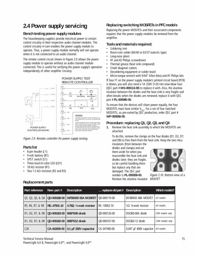
2.4 Power supply servicingBench testing power supply modulesThe housekeeping supplies provide electrical power to certaincontrol circuitry in their respective audio channel modules. Thecontrol circuitry in turn enables the power supply module tooperate. Thus, a power supply module normally will not operatewhen it is not connected to an audio channel.
The remote control circuit shown in Figure 2.9 allows the powersupply module to operate without an audio channel moduleconnected. This is useful for verifying the power supply’s operationindependently of other amplifier circuitry.
Parts list• 8-pin header (J1)• 9-volt battery (B1)• SPST switch (S1)• Three-lead tri-color LED (LD1)• 18 kΩ resistor (R1)• Two 1.5 kΩ resistors (R2 and R3)
ecnerefertraP #trapweN noitpircseD #trapdlosecalper… noitpircseD ?sledomhcihW
4Q&,3Q,2Q,1Q 00-881000-DQ TEFSOMA5505N55FXI 00-911000-DQ TEFSOMA8405N84FXI sledomllA
8R&,7R,6R,5R 01-10574.-ER 57.4 ΩΩΩΩΩ rotsiserttaw-¼ 01-20001.-ER 1Ω rotsiserttaw-¼ sledomllA
8D&,7D,2D,1D 00-381000-DQ edoid80SPE06 00-621000-DQ edoidA60-06IESD ylnosledomV021
8D&,7D,2D,1D 00-281000-DQ edoid21SPE06 00-761000-DQ edoid21-06IESD ylnosledomV032
02C 00-900014-AC roticapacV052Fµ1.0 00-004743-AC roticapacV004Fµ740.0 sledomllA
Replacement parts
Replacing switching MOSFETs in PFC modelsReplacing the power MOSFETs and their associated componentsrequires that the power supply modules be removed from theamplifier.
Tools and materials required:• Soldering iron• Rosin-core solder (60/40 or 63/37 eutectic type)• Long-nose pliers• #1 and #2 Philips screwdrivers• Thermal grease (heat sink compound)• Small diagonal cutters• Desoldering equipment or solder braid• Micro-torque wrench with 9/64” Allen (hex) and #1 Philips bitsIf fuse F1 on the power supply module’s printed circuit board (PCB)is blown, you will also need a 1A 250V 5×20 mm slow-blow fuse(QSC part # MS-000113-00) to replace it with. Also, the aluminainsulator between the diodes and the heat sink is very fragile andoften breaks when the diodes are removed; replace it with QSCpart # PL-000085-00.
To ensure that the devices will share power equally, the fourMOSFETs must have similar VDSS. For a set of four matchedMOSFETs, as pre-sorted by QSC production, order QSC part #WP-000056-00.
Procedure: replacing Q1, Q2, Q3, and Q41. Remove the heat sink assembly to which the MOSFETs are
attached.
To do this, remove the clamps on the four diodes (D1, D2, D7,and D8) to free them from the heat sink. Keep the two micainsulators (from between thediodes and clamps) and setthem aside for when youreassemble the heat sink anddiodes later; they are fragile,so be careful handling thembut replace any that aredamaged. The QSC partnumber is PL-000059-00.Remove the alumina insulator
Figure 2.10. Bottom view of aMOSFET
THIS REMOTE CONTROL IS USED TO TURN ON THEPFC POWER SUPPLY VIA J100 ON THE CONTROLLERBOARD.
CLOSING POWER SWITCH S1 ENABLES THE POWERSUPPLY, AND LED LD1:2 WILL GLOW GREEN.
LED1:1 WILL ALSO LIGHT, AND THE RESULTINGCOLOR WILL BE YELLOW-ORANGE.
WHENTHE AC INPUT VOLTAGE APPLIED TO THE PSMODULE REACHES THE TURN-ON THRESHOLD (65VAC FOR 120V UNIT OR 130 VAC FOR 230V UNIT),POWER SUPPLY
CONTROLLER BOARD
POWER SUPPLY TESTREMOTE CONTROLLER
Figure 2.9. Remote controller for power supply testing.

16 QSC Audio Products, Inc.TD-000083-00
(from between the diodes and the heat sink); it is extremelyfragile, so it is best to replace it during reassembly with anew one.
Then remove the 16 screws that attach the MOSFETs to theprinted circuit board (PCB); if the MOSFETs are blown, someof the mounting screws may be melted or damaged. The newMOSFETs come with new mounting screws with captivewashers, so there is no need to save old ones for reuse.
Remove the other four mounting screws so that the heat sinkassembly is free from the circuit board. Set the hardwareaside.
Find where the twisted wire lead from the heat sink’s thermalsensor attaches to a pair of pins on the board, and unplug it.Detach the gate drive cable, which is an 8-conductor ribboncable that plugs into an 8-pin header. Lift the heat sink andMOSFET assembly from the board. If the strip of fishpaper(Figure 2.11) remains stuck to the PCB, leave it there; if itcomes loose, set it aside for re-assembly later.
2. Remove the MOSFETs from the heat sink. Thoroughly clean theold thermal grease off the heat sink. Apply fresh thermalgrease to the new MOSFETs (QSC part # QD-000188-00) andattach them to the heat sink.
Make sure the new MOSFETs are correctly oriented. One endof each MOSFET has a mounting hole, while the other has anopen-ended slot (see Figure 2.9). Each MOSFET must bemounted so the slot end faces away from the diode end of theheat sink (see Figure 5.11). Try to get the MOSFETs evenlyspaced and as close to perfectly in line as you can. The silkscreen print on the circuit board (see Figure 5.12) shows thecorrect orientation.
Tighten the MOSFET mounting screws to 32–35 lb-in (3.6–4.0N-m) torque. Do not over-torque them.
3. Remove the four diodes on the circuit board (D1, D2, D7, andD8). See Figure 2.12.
4. Check the value and rating labeled on capacitor C20 (seeFigure 2.13). If it is not a 0.1 µF 250V capacitor (early moduleswill have the original 0.047 µF 400V component instead),replace it with QSC part # CA-410009-00.
5. Remove resistors R5 through R8 (see Figure 2.11) and replacethem with 4.75Ω ¼-watt resistors (QSC part # RE-.47501-10).
6. Set the MOSFET and heat sink assembly upside-down andplace the PCB on top of it. Make sure all the threaded holes inthe heat sink and the MOSFETs line up exactly with the holesin the board. If any MOSFETs don’t line up, reposition them sothey do because misaligned mounting screws can damagethem when tightened.
Make sure the fishpaper strip is in place, and then reattachthe MOSFET and heat sink assembly to the PCB. Make sureyou use the correct screws and washers in each location.Tighten the four heat sink screws to 32–35 lb-in (3.6–4.0 N-m)torque and the MOSFET mounting screws to 12 lb-in (1.4 N-m). Do not over-torque them.
CAUTION: Overtightening its mounting screws will destroy aMOSFET. When tightening a screw, use the split lockwasheras a visual guide; as soon as it is flattened, the screw is tightenough.
Plug the thermal sensor lead onto its two pins on the circuitboard.
7. Clear any solder from the circuit board holes for the four diodes.
Apply a thin coating of new thermal grease to both sides ofthe alumina strip and set it in place on the heat sink.
Insert the four new diodes (120V models: QSC part #QD-000183-00; 230V models: QSC part # QD-000182-00) intotheir holes in the PCB, but do not solder them in place yet.Then set the two mica insulators in place over the diodes(they will overlap in the middle), and clamp and fasten thediodes to the heat sink; tighten the screws to 32–35 lb-in(3.6–4.0 N-m) torque. Do not over-torque them. As you do
Figure 2.10: The heat sink assembly, with all four MOSFETsattached. The “diode” end of the heat sink is at right; the slots inthe MOSFETs would face to the left.
Figure 2.11. The silk screen on the circuit board shows thecorrect orientation of the MOSFETs. This photo also showsthe four resistors (R5–R8) to be replaced.
“Diode”end ofheat sink

Technical Service Manual 17PowerLight 6.0 II, PowerLight 6.0PFC, and PowerLight 9.0PFC
this, make sure the diodes are straight and evenly spaced, andreposition them if necessary.
8. Solder the four diodes to the circuit board.
9. Reattach the gate drive cable.
10. Check the fuse (see Figure 2.14). If it is blown, replace it witha slow-blow 1A 250V 5×20 mm fuse (QSC part #MS-000113-00).
11. Repeat the procedure for the other channel’s power supplyboard if it also has failed or is to be updated.
Suggestions for troubleshootingIf you are repairing a failed power supply module and not simplyupgrading a working one, you should determine whether othercomponents have also failed.
Typical collateral failures around PFC power supply module failuresinclude:Blown high rail diodes: Check D12 and D14 for sooty or
blackened thermal grease around their edges or for any othersigns of damage. If you suspect that they might be damaged,remove them from the circuit board and check them with thediode test function on a DMM. Replace them if necessary(QSC part # QD-000126-00). These diodes are clamped ontothe other heat sink, at the end next to the power transformer.If you remove the diodes, thoroughly clean away the oldthermal grease from that portion of the heat sink and fromthe mica insulators; apply fresh thermal grease when youreassemble or replace them.
Blown driver ICs: The two MIC4452BN MOSFET driver ICs, U1and U3, are under the MOSFET heat sink. Frequently, whenMOSFETs fail, the driver IC associated with the transistor(s)fails, too. The IC’s QSC part # is IC-000064-00.
Fuses: Conditions that cause the MOSFETs to fail also frequentlycause the fuses on the AC line filter to blow. The filter circuitboard runs along the side of the amplifier between the AC powercable and the AC power switch. Each channel has two fast-blowceramic AC fuses, for a total of four (120V models: 125V 25A,QSC part # MS-000112-00; 230V models: 250V 15A, QSC part #MS-150250-FU). Check them and replace any that are blown.Also on the AC line filter board are the housekeeping suppliesfor each channel; if they do not work, the channels will notstart even if the power supply modules are in perfect workingorder. The housekeeping supplies each use a 250V 1A slow-blow fuse (QSC part # MS-000113-00).
Fuse F1
Capacitor C20
Figure 2.12. These four diodes need to be replaced.
Figure 2.13. Capacitor C20 may also needreplacement. See the text.
Figure 2.14. Fuse F1 may need replacing.

18 QSC Audio Products, Inc.TD-000083-00
Adjusting and calibrating the power supplymoduleAdjusting and calibrating the power supply card will help ensurethe success of the repair; this portion of the service bulletindescribes a series of five procedures for doing so. Because of thespecialized nature of the power supply fixture required for theseprocedures, it can only be performed at the QSC factory by trainedpersonnel. Follow these procedures exactly and in order.
There are four trimpots, VR1–VR4 (see Figure 2.14), on thecontroller card that must be adjusted correctly before reinstallingthe power supply in the amplifier:VR1 On the PL 9.0PFC, this trimpot sets VOUT/32; on the PL 6.0PFC, it
sets VOUT/26.6.
VR2 This trimpot is for balancing the transformer to the PFC circuitry.
VR3 This trimpot sets the maximum 2-ohm output power. For thePL 9.0PFC, it will be set for 4500 watts @ 2 ohms at 2 kHz; forthe PL 6.0PFC, it will be set for 3600 watts @ 2 ohms at 2 kHz.
VR4 This trimpot sets the power supply’s idle voltage. For the PL9.0PFC, it will be set for 191.3 volts DC; for the PL 6.0PFC it willbe 166.5 volts DC.
Tools and materials needed:• PFC power supply fixture with external power supply and CMP
(Control-Monitor-Power) box• Two digital multimeters (DMM #1 and #2) with clip-on leads• Digital multimeter (DMM #3) with clamp-on AC current probe• 0–240 VAC Variac™, Powerstat™, or similar variable AC
transformer; 60 amperes or higher rating, with RMS voltageand current metering
• 120 VAC power (for the fixture’s housekeeping supply)• Four-channel oscilloscope with ×1/×10 probes• Oscilloscope with differential probe (optional; see
step 10 of the VOUT procedure)• Small pocket-type flat-blade screwdriver• Grounded anti-static work surface• Audio Precision (AP) workstation with PFC test
procedure files* and 2-ohm load resistor banks(mimimum power handling capacity: 1250 watts per8-ohm resistor; 5000 watts total in 2-ohm configura-tion).
*The four AP test procedure files are available on the QSC TechnicalSupport CD-ROM: Pfcxf.tst; Pfcpwr2k.tst; Pfcpwr20.tst; andPfctherm.tst.
The PFC power supply fixtureThe PFC power supply fixture is a special test bed for PowerLight 6.0and 9.0 supply modules. It has the necessary connections andindicators for adjusting, calibrating, and testing the modules. Italso contains one audio channel of a PowerLight 9.0 to allowtesting of the module’s capability to power an actual amplifierchannel. The fixture is custom built by QSC.
Front panel switches and indicators
From left to right (Figure 2.14):• Power switch. For the AC lines to the power supply module
being tested.• Power indicator. It lights when the fixture is connected to AC
power and is turned on.• Blown fuse indicator. Connected across the large fuse under
the door in the top of the fixture chassis, this indicator will lightif the fuse blows. The fuse, however, is merely a backup in casethe CMP box’s solid-state electronic fuse malfunctions.
• Protect, Standby, and Power indicators. In the portions ofthe test that use the amplifier channel, these LEDs function justas they do on a regular amplifier.
• Fan switch. Some portions of these procedures require themodule fans running, and others need them off.
• “Set VOUT” switch. This switch is used for the first procedure.• “ISET” switch. This switch also is used in the first procedure
for checking the module’s ISET circuit.• “ISET” indicator. This tri-color LED indicates the status of the
module’s ISET circuit.
Rear panel switches and attachments
From left to right (Figure 2.15):• Audio input. This is where to connect the signal output from
the AP workstation.• DC high rail outputs. These are two pairs of red and black
binding posts, and they carry the DC output of the supplymodule’s high rails. Connect DMM #1 to one of these sets ofbinding posts.
• Audio output. This Neutrik Speakon connector carries theaudio output of the fixture’s amplifier channel. Connect this
VR1
VR2
VR3VR4
Figure 2.16. The front of the fixture. The amplifier channel’s gain control isto the right, out of the picture
Figure 2.15. The locations of the four trimpots, VR1–VR4

Technical Service Manual 19PowerLight 6.0 II, PowerLight 6.0PFC, and PowerLight 9.0PFC
output to the AP workstation and to the load resistors.• Transformer flux sample. Connect the tip of an oscilloscope’s
×1 probe to the exposed conductor at the tip of this attach-ment, and connect the probe’s reference clip to the loop. This isused in the transformer balancing, the third procedure in thesupply module adjustment and calibration.
• DC supply input. This dual binding post set is for connectingthe fixture to the external power supply.
• 120 VAC power cord. This connects to a regular AC outlet andprovides power for the fixture’s “housekeeping” supply, whichpowers the various circuits and indicators.
• Housekeeping supply power switch. This small rockerswitch lets you turn off the housekeeping supply when thefixture is not in use.
• Fixture power cord. This large power cord connects to theVariac and provides AC power for the power supply moduleunder test.
Other attachments
See Figure 2.17.• Lower barrier strip. Connect the supply module’s five black
DC rail wires to the lower barrier strip’s terminals for the firstprocedure, setting VOUT.
Procedure 1 of 5: Setting VOUT1 Turn off all power to the fixture and turn the Variac all the
way down. Set the power supply module in place atop thefixture, as shown in Figure 2.18.
2 On the test fixture, set switches VOUT/32 and ISET in the upposition. Turn off the fan switch.
3. On the power supply module, disconnect the gate drive cable(Figure 13).
4. Connect the two AC line wires to the stud terminals on thePCB: white to E2 on the left, black to E3 on the right. Use thelong insulated threaded posts to secure the wires to theterminals.
5. Connect the power supply module’s five black DC outputwires, labeled 0 through 4, to the screw terminals on thelower barrier strip (Figure 10). Keep them in order; do notcross any of them.
6. The external power supply has two dual banana sockets—oneis labeled active and the other, dummy. Connect the fixture’sdual banana plug to the external power supply’s active socket.
7. Plug the AC lines for both the external DC supply and thefixture into the Variac.
8. Set the CMP boxe’s electronic fuse to a trip threshold of 5amperes.
Audio signal inputfrom Audio Precision
workstation
Audio signal outputto Audio Precision
workstation and loadresistors
120 VAC for fixture'shousekeeping supply
(Do not connect to Variac!)
DC high rail outputs: forPL 9.0 ; for PL 6.0
The two sets of binding posts arein parallel. Connect DMM #1 to
one set.
191.3 V166.5 VPFC PFC
Red = +; Black = -
Transformer flux samplefor balancing procedure.Connect to oscilloscope
using ×1 probe.
Connect to external DCsupply. Watch polarity:
Red = +; Black = -
Power switch forhousekeeping
supply.
Ext. DCsupply
AC connection
Solid-state fuse
Switches andLED indicators
• Upper barrier strip. Connect theDC rail wires to the upper barrierstrip for the other procedures.
• Control connection. Above thebarrier strips is a multiconductorcable that connects to the 8-pinheader on the controller card of thepower supply module under test.
• AC wires. Located at the top of thefront panel, these two wires connectto points E2 and E3 on the supplymodule.
Figure 2.17. The fixture’s rear panel.
Figure 2.18. The two barrier strips. Use the lowerone for the first adjustment (setting VOUT/32 or VOUT/26.6), and the upper one for the other adjustments. Figure 2.19. The power supply module loaded onto the test fixture.

20 QSC Audio Products, Inc.TD-000083-00
9. Connect DMM #1 to one set of the parallel DC VOUT terminalson the back of the fixture. Connect DMM #2 to the controllercard, with the ground or reference lead on the tab of U8, a+12V regulator, and the hot lead on the left leg of capacitorC34. On the board, this point is labeled “VOUT/32.”
10. Note: this step is optional because the replacement diodesspecified in this bulletin do not have the leakage problemsthat many of the original fast diodes had. Through a differen-tial probe, connect an oscilloscope input between resistor R31(labeled “OSC”) and ground; this will allow you to view theoutput of the diodes to see if any are leaky.
11. Turn the fixture power switch on. Turn up the Variac graduallyuntil DMM #1 reads 190 volts DC (for the PL 9.0) or 166 volts(for the PL 6.0). You don’t need to measure the AC voltagefrom the Variac yet.
12. Adjust VR1 to obtain a reading on DMM #2 of 5.94 volts DC(for the PL 9.0) or 6.20 volts DC (for the PL 6.0).
13. Flip the ISET switch down. If the LED indicator next to theswitch lights green or orange, ISET is good; if red, it is bad andshould be rejected for controller board replacement or repair.
14. Turn down the Variac all the way. Turn off the fixture’s ACswitch. Unplug the external supply’s AC line from the Variac.
15. Set the ISET and VOUT/32 switches down. Remove DMM #2’sleads from the controller card.
16. Wait a few seconds for the capacitors to discharge and DMM#1’s voltage reading to drop to 60 volts or less.
Procedure 2 of 5: Adjusting idle voltage1. Re-attach the gate drive cable on the power supply module.
Also, disconnect the five DC rail output wires on the right endof the module from the lower barrier strip and attach them tothe corresponding screw terminals on the upper barrier strip.Make sure the screw connections are tight and secure.
2. Turn the fixture’s AC switch on and turn the Variac up to theappropriate AC voltage: 120 volts AC for a 120V module, or230 volts AC for a 230V module. The power supply will turnon and begin to draw current when the AC voltage reachesabout the halfway point.
3. Adjust VR4 to obtain the a reading of 191.3 volts DC (for thePL 9.0) or 166.5 volts DC (for the PL 9.0) on DMM #1.
AC voltage
Trip set switch up:
Trip set switch down:reads AC current;
reads trip current setting
0–280 VAC infrom Variac
Adjusts trip currentof solid state fuse
Indicates that thesolid state fuse
circuit has tripped
Press switchdown and backup to reset thesolid state fuse.
Trip set switch:for normal solid state fuse function;
to set solid state fuse tripUP
DOWN
AC currentsample for
external DMM100 mV = 1.0 A
The CMP boxThe CMP box has two digital panel meters that monitor ACvoltage and current and a solid-state electronic AC fuse thatcan be set to trip specific current levels from 0 to 100amperes.
To set the current trip level, flip the trip set switch down;the AC ammeter will then read the trip current setting. Usethe trip set knob to adjust the desired trip point, then flipthe switch up.
The BNC jack provides an AC voltage proportional to the ACcurrent: 100 mV RMS = 1.0 ampere RMS. This is useful inthe transformer balancing procedure because it allows theuse of an external voltmeter with finer resolution (>3 decimalplaces) than the panel ammeter has.
Important note about repaired PFC powersupply modulesAfter repairing a failed power supply module that hadalready been calibrated before its failure, either in produc-tion or in Technical Services, the VOUT/32 and VOUT @idle voltages in Procedure 1 only need to be checked andnot fully adjusted, unless the measured high rail voltage isnot 191.3 volts, ±1.5 volts, for the PL 9.0 or 166.5 volts, ±1.5volts, for the PL 6.0. If the high rail voltages are outside thisrange, then the module will require full adjustment andcalibration.
Gate drive cable
Figure 2.20. The CMP box. The variable AC outlet forthe test fixture is on the back of the box.
Figure 2.21. The gate drive cable for the MOSFETs.Disconnect it here for the VOUT procedure.

Technical Service Manual 21PowerLight 6.0 II, PowerLight 6.0PFC, and PowerLight 9.0PFC
Procedure 3 of 5: Adjusting transformer balanceThis is done in three stages. In the first two, watch the trans-former flux “bubble” waveform on the oscilloscope, and on thethird, adjust the AC current to a minimum. To prevent overcurrentcutback due to undervoltage, adjust the Variac to 130 volts for120-volt modules or 260 volts for 230-volt modules.1. Set the CMP box’s electronic fuse to a trip threshold of 20
amperes (for a 120V module) or 10 amperes (for a 230Vmodule) and turn on the fans.
2. Start the PFC test file (Pfcxf.tst) on the AP workstation. It willput out a 2 kHz sine wave at 0.1 volt RMS and will switch theload resistance to 2 ohms. Turn the fixture’s gain control allthe way up.
3. Step the signal level up in 0.1 volt increments and watch thetransformer flux “bubble” signal on the oscilloscope (verticalscale: 20 or 50 V/div; horizontal scale: 1 or 2 ms/div; ×1 scale).At each step, adjust VR2 to get a smooth, balanced signal.See Figure 14. There should be no spurious oscillations ornoise visible.
4. When the audio signal reaches a particular level, the CMP box’selectronic fuse will trip. Set the audio signal back to 0.1 volt.
5. Reset the trip point to 40 amperes (for a 120V module) or 20amperes (for a 230V module) and repeat steps 2 and 3. Theelectronic fuse should trip at about 2.8 kW of output(measured on the AP), with approximately 1.4 volts input.
6. Reduce the AP’s signal level to 0.1 volt. Reset the electronicfuse and increase the signal level so that the output is about2.5 kW. Gently adjust VR2 to null the AC current on DMM #3to a minimum.
7. Turn the Variac down to zero and set the electronic fuse to 60amperes.
Procedure 4 of 5: Adjusting 2-ohm limits1. If this is a brand new module (not a repair), set VR3 to
approximately 4 o’clock. If it is a repair or has otherwisealready been calibrated at some time, leave VR3 alone untilafter the first power sweep.
2. Set the Variac to 130 volts (for 120V modules) or 260 volts(for 230V modules).
3. Run the AP test file (Pfcpwr2k.tst) for a 2-ohm power sweeptest at 2 kHz.
4. Watch the power sweep on the AP monitor and see wherethe power cutback occurs. The target output power level at2 kHz is about 4.6 to 4.7 kW for the PL 9.0 or 3.6 to 3.7 kW forthe PL 6.0. If the cutback point is not in the target range,carefully adjust VR3 and then repeat the power sweep. It maytake more than two or three tries to get the right setting.
CAUTION: During the power sweep, keep a finger on thereset switch of the CMP box. If anything abnormal happens,such as power cutback at a low level, or audible noise fromthe supply module’s transformers, immediately flip the resetswitch down and hit F1 on the AP computer keyboard to abortthe sweep test.
If you stopped the test due to transformer noise, go back andstart over at the transformer balancing procedure. If you hadnot aborted the power sweep, in a short time you would havedestroyed the MOSFETs.
If you stopped the test for any other abnormality, you musttroubleshoot and repair the supply module before continuing.
5. Load the AP test file Pfcpwr20.tst, which will change thesignal frequency to 20 kHz, and repeat step 4. This time, verifythat the power cutback does not occur until approximately 4.5kW for the PL 9.0 or 3.6 kW for the PL 6.0.
6. After competing the power sweeps, press F1 on the APcomputer keyboard.
Procedure 5 of 5: Thermal test1. On the AP workstation, load the thermal test file
Pfctherm.tst. It should select the Pseudo (pink noise)waveform at 2.7 volts RMS amplitude. Make sure the fixture’sgain control is turned up full. Load the fixture output with the2-ohm resistance and shut off the fans.
2. The power supply module should shut down within oneminute. The PROTECT indicator LED on the front panel willlight.
3. After the module shuts down, turn on the fans and await itsrecovery.
Figure 2.22. A well-balanced transformer flux“bubble.”

22 QSC Audio Products, Inc.TD-000083-00
4. Turn off the fixture’s AC switch. Turn down the Variac to zero.Turning off the fixture’s AC switch will automatically bleed thecapacitors down. Disconnect the module from the test fixtureand set the AP workstation back to sine wave and 0 volt RMS.
2.5 AC voltage conversionsWARNING: Regulatory agencies require that any operatingvoltage conversions from 120 volts to any other voltage be doneonly by QSC’s factory service. Any other operating voltageconversions may be done only by a QSC-authorized service centeror international distributor.
The power supply modules and line filter modules in thePowerLight 6.0 II, PowerLight 6.0PFC, and PowerLight 9.0PFC aremade for specific AC line voltages; they cannot be converted fromone to another. To convert an amplifier from120 to 230 volts AC orvice-versa requires replacing both power supply modules and theAC line filter. For this reason, it is seldom economically justifiableto convert one of these models.
2.6 Bias adjustmentsThese three amplifier models have a trimpot for bias adjustmenton each audio channel. However, adjusting it is far more complexthan on most amplifiers, so it should only be done when workingon the module at board level, or as an emergency measure if themodule is running too hot at idle.

Technical Service Manual 23PowerLight 6.0 II, PowerLight 6.0PFC, and PowerLight 9.0PFC
3. TroubleshootingBecause of the high complexity of the circuitry used in theamplifiers covered by this manual, most, if not all, of yourtroubleshooting efforts will be at board level. Proper component-level troubleshooting and service will also usually requirespecialized test fixtures that may not be economically sensible tohave unless you do a high volume of service work on theseamplifiers. See the Servicing chapter of this manual for informa-tion on these fixtures.
3.1 Initial checkWhen first checking the operation of a suspect amplifier on thebench, always turn your variable transformer down to zero beforeplugging the amplifier in. After you turn the amplifier on, graduallyturn up the AC voltage as you observe the amplifier’s behavior andits current draw; this will help you determine what, if anything, iswrong with it. If you see or smell smoke, flames, or any other signsof short circuits or excessive current draw, quickly turn the AC backdown to zero. If no such problems occur, it is usually safe to turn theAC up to the amplifier’s full operating voltage for further testing.The following procedure will help you determine if the amplifierhas a problem and if so, where it may be located.
Starting at zero volts1. Start with the variable transformer at zero.
2. Connect an AC voltmeter to monitor the transformer outputand an AC ammeter to monitor the current delivered to theamplifier.
3. Connect the amplifier to the output of the variable trans-former.
4. Turn on the amplifier.
LED activity starts5. Gradually turn up the AC voltage. When it reaches about 25%
of the amplifier’s operating voltage (30 volts for a 120-voltmodel or 60 volts for a 230-volt model), the power LEDs onboth channels should start to flicker. By the time it reachesabout 40% (50 volts for a 120-volt model or 100 volts for a230-volt model), both power LEDs and both protect LEDsshould be on.
6. Continue increasing the AC voltage. When it reaches about 70volts (120-volt model) or 140 volts (230-volt model), bothprotect LEDs should go out and all four fans should start up.
Check current draw7. At this point, the current draw for a PowerLight 6.0PFC or
PowerLight 6.0 II should be about 2 A or less for a 120-voltmodel or 1 A or less for a 230-volt one. For a PowerLight9.0PFC, it should be about 2.5 A or less (120-volt model) or 1.25A or less (230-volt model).
8. If all is well, you can safely increase the AC voltage to theamplifier’s normal operating level and test its audio perfor-mance. Once the AC voltage is at full, the amplifier shouldbehave normally. On the left side of the front panel, the twopower LEDs should be lit, while the standby and protect LEDsshould not. On the right, the signal, -20 dB, -10 dB, and clipLEDs should light only in response to an output signal. If theydo not, continue by following the preliminary troubleshootingguide.
3.2 Preliminary troubleshootingAbnormal behavior of the amplifier indicates some problem in oneor more of its parts. You can use the observed patterns of thisbehavior to help deduce where the problem lies. The amplifier hastwo channels with independent power supplies; a defect may existon one channel that does not affect the other.
Power, Standby, and Protect LEDs: None lit on oneor both channels• The main fuse for the affected channel(s) may be blown. The
main fuses are located in the line filter assembly and areaccessible when the amplifier’s top cover is removed.
• The audio module’s housekeeping supply is not working on theaffect channel(s). This is a rare failure because the house-keeping supply has very reliable protection against shortcircuits and other possibly destructive situations. Without itshousekeeping supply, though, the audio module cannot signalthe power supply module to turn on.
Protect LED lit• If the Protect LED lights steadily, without interruption, the
power supply module is not working.
• If the amplifier is hot, it has probably overheated and will stayin protect until it cools down to a safe temperature.
Amplifier endlessly cycles on, into protect, andthen off, and over again• There is a defect in the audio module—probably in the output
circuitry—that prevents the power supply module, as it startsup, from reaching its proper rail voltages or places DC on theoutput. When this happens the channel immediately switchesinto protect, and then the power supply resets and tries tostart again.

24 QSC Audio Products, Inc.TD-000083-00
3.3 Further troubleshootingThis procedure allows you to further isolate the problem anddetermine which board or module is defective.
Start at zero volts1. Turn the variable transformer to zero and turn the amplifier
off.
Open the amplifier2. Remove the top cover of the amplifier. See the Servicing
chapter for instructions and diagrams.
3. Check the continuity of the two main fuses, located at the topof the line filter assembly near the front of the amplifier.Replace any that are open.
Ramp up the AC voltage4. Turn up the AC voltage to about 30 volts (120-volt model) or
60 volts (230-volt model).
5. Using pliers, pull the connectors for the two housekeepingsupply wires off of the audio module of the affected channel.Measure the voltage between the wires. It should beapproximately 40 volts DC. If the voltage is significantly loweror is not there at all, there may be a problem with the portionof the housekeeping supply that is on the line filter assembly.
6. If the voltage is good, reconnect the housekeeping supplywires.
7. Disconnect the latching connector on the cabling that goes tothe input board. If the channel now starts up, then theproblem was on the input board—perhaps a defective opamp; replace or repair the input board.
8. If disconnecting the input board did not make the channelstart up, reconnect it and turn the amplifier off.
9. Disconnect the power supply control ribbon cable from the 8-pin header on the audio module. Attach the power supplyremote controller (See the section on servicing powersupplies in Chapter 2) to the ribbon cable.
10. Loosen the screw terminals of the five power supply wires atthe front of the audio module. Remove the wires from theterminals and make sure they are arranged so none of themwill short out against anything.
11. Turn switch S1 on the remote controller to on and turn theamplifier on. The LED on the remote controller should glowgreen.
12. Increase the AC voltage to 65 volts (120-volt model) or 130volts (230-volt model).
13. Measure the voltages on the supply wires 1 through 4, usingwire 0 as a reference.

PowerLight 9.0PFC, PowerLight 6.0PFC, PowerLight 6.0 II Service Manual 25Parts lists
4. Parts4.1 Semiconductor package descriptions and pinoutsLegend: A = anode; B = base; C = collector; D = drain; G = gate; K = cathode; S = source
IC-000047-30Comparator, dual, LM393; 8-pin SMT
1
2
3
4
8
7
6
5
A B
OUTPUT A
INVERTINGINPUT A
NON-INVERTINGINPUT A
GND
OUTPUT B
INVERTINGINPUT BNON-INVERTINGINPUT B
V+
IC-000046-30Op amp, dual, TL072; 6-pin SMT
IC-000048-30Op amp, dual, MC33078; 6-pin SMT
1
2
3
4
8
7
6
5
A B
OUTPUT A
INVERTINGINPUT A
NON-INVERTINGINPUT A
V-
OUTPUT B
INVERTINGINPUT BNON-INVERTINGINPUT B
V+
IC-000024-00Controller, PWM, SG3525AN; 16-pin DIP
1
2
3
4
5
6
7
8
16
15
14
13
12
11
10
9
SYNC
RT
VRE F
OUTPUT B
VC
GROUND
SHUTDOWN
COMPENSATION
OUTPUT A
VCC
INV. INPUT
NON-INV. INPUT
OSC. OUTPUT
CT
DISCHARGE
SOFT START
IC-000051-00Opto isolator, MOC8101; 6-pin DIP
1
2
3
6
5
4
NC
NC
IC-000031-00Opto isolator, 4N30; 6-pin DIP
1
2
3
6
5
4
IC-000042-00Voltage regulator, +5V, MC7805CT; 3-pin TO-220
OU
TPUT
GRO
UN
DIN
PUT
GROUND
IC-000049-00Opto coupler, HCPL2200; 8-pin SMT
1
2
3
4
8
7
6
5
NC
ANODE
CATHODE
NC
VO
VE
GND
VCC
SHIELD
HHLL
ONOFFONOFF
ZZHL
LED ENABLE OUTPUT
TRUTH TABLE(POSITIVE LOGIC)
IC-000050-00Opto coupler, 6N137; 8-pin DIP

26 QSC Audio Products, Inc.TD-000083-00
IC-000053-30Timer, dual, LM556; 14-pin SMT
1
2
3
4
5
6
7
14
13
12
11
10
9
8
OUTPUT
RESET
CONTROL VOLTAGE
THRESHOLD
DISCHARGE
TRIGGER
GROUND
Flip
-flop
Comp.
Comp.
Flip
-flop
Comp.
Comp.OUTPUT
RESET
CONTROL VOLTAGE
THRESHOLD
DISCHARGE
VCC
TRIGGER
IC-000054-30Comparator, quad, LM339AM; 14-pin SMT
1
2
3
4
5
6
7
14
13
12
11
10
9
8
INPUT 1+
INPUT 1-
V+
OUTPUT 1
OUTPUT 2
INPUT 2-
INPUT 2+
INPUT 3-
INPUT 4+
INPUT 4-
GROUND
OUTPUT 4
OUTPUT 3
INPUT 3+
1
2 3
4
IC-000059-00Top switch, TOP202; TO-220
IC-000235-00Top switch, TOP224; TO-220
DRA
INSO
URCE
CON
TROL
IC-000055-30Regulator, power factor, UC3854B; 16-pin SMT
12345678
161514131211109
GNDPKLMT
CAOISENSEMOUT
IACVAO
VRMS
GTDRVVCCCTSSRSETVSENSEENAVREF
IC-000056-30Driver, MOSFET, TC4427; 8-pin SMT
1234
8765
NCIN AGNDIN B
NCOUT AVDD
OUT B
2,4 7,5
IC-000057-30Counter, ripple, 74HC4024, SMT; 14-pin SMT
1234567
141312111098
CPMRQ6Q5Q4Q3
GND
VCC
NCQ0Q1NCQ2NC
IC-000060-00Oscillator, clock, 6.000 MHZ; 4-pin DIP
1
7
14
8
OE
GND
VDD
OUT
IC-000063-30Op amp, quad, MC33074; 14-pin SMT
1
2
3
4
5
6
7
14
13
12
11
10
9
8
NON-INV. 2
VCC
NON-INV. 1
INV. 1
OUT 1
INV. 2
OUT 2
INV. 3
NON-INV. 3
VEE
NON-INV. 4
INV. 4
OUT 4
OUT 3

PowerLight 9.0PFC, PowerLight 6.0PFC, PowerLight 6.0 II Service Manual 27Parts lists
IC-000067-30Differential amplifier, dual, CA3054; 14-pin SMT
1
2
3
4
5
6
7
14
13
12
11
10
9
8
NCSUBSTRATE
Q1Q2
Q3 Q4
Q5 Q6
IC-000072-OPOp amp, dual, TL072; 8-pin DIP
1
2
3
4
8
7
6
5
A B
OUTPUT A
INVERTINGINPUT A
NON-INVERTINGINPUT A
V-
OUTPUT B
INVERTINGINPUT BNON-INVERTINGINPUT B
V+
IC-000064-00Driver, MOSFET, 4452BN; 8-pin DIP
1
2
3
4
8
7
6
5
VS
IN
NC
GND
OUT
OUT
GND
VS
IC-000070-30Voltage reference, +2.5V, LM4040DIM3X-2.5; 3-pin SOT-30 (SMT)
1
2
3
IC-000071-00Sensor, temperature, LM35DZ; TO-92
+VS
VO
UT
GN
D
IC-000073-30Transconductance op amp, DUAL, LM13600M; 16-pin SMT
1
2
3
4
5
6
7
8
16
15
14
13
12
11
10
9
A B
NON-INVERTINGINPUT A
V-
AMP BIAS INPUT B
NON-INVERTINGINPUT B
INVERTING INPUT B
OUTPUT B
BUFFER INPUT B
BUFFER OUTPUT B
V+
DIODE BIAS B
AMP BIAS INPUT A
DIODE BIAS A
INVERTING INPUT A
OUTPUT A
BUFFER INPUT A
BUFFER OUTPUT A
IC-000085-00Voltage regulator, +12V, LM2937ET-12, low drop out; TO-220
OU
TPUT
GRO
UN
DIN
PUT
GROUND
IC-000133-30Comparator, single, LM311; 8-pin SMT
1
2
3
4
8
7
6
5
GROUND 1
NON-INVERTINGINPUT
INVERTINGINPUT
V-
OUTPUT
BALANCE/STROBE
BALANCE
V+

28 QSC Audio Products, Inc.TD-000083-00
IC-000134-00Driver, MOSFET, IR2110; 14-pin DIP
1
2
3
4
5
6
7
14
13
12
11
10
9
8
HIN
VDD
SD
LIN
VSS
VS
VB
HO
VCC
COM
LO
QD-000022-QDDiode Zener, 18V, 1W, 1N4746A, DO-41
QD-000023-QDDiode Zener, 180V, , 1.5W, 1N5955A, DO-41
QD-000047-00Diode Zener, 200V, , 1.5W, 1N5956B, DO-41
QD-000080-20Diode Zener, 11V, 1W, 1N4741A, DO-41
QD-000159-20Diode Zener, 47V, 1W, 1N4756, DO-41
QD-000159-20Diode Zener, 47V, , 1W, 1N4756, DO-41
A K
QD-000042-00Diode rectifier ultrafast, 400V, 3A, MUR440, DO-201AD, 50 ns
A K
PD-000036-30Power supply signal management, GAL16V8, PL9.0PFC and PL6.0PFC
This device must be programmed by QSC before installation.
QD-000024-QDDiode Zener, 6.2V, , 0.25W, DZ901116G, DO-35
A K
QD-000052-00LED green, T-1, diffused
QD-000053-00LED yellow, T-1
QD-000054-00LED red, T-1
AN
OD
E
CATHO
DE
23 20 1918
16
1413119
8
6
4
I I I/CLK Vcc I/O/Q
I GND I/OE I/O/Q I/O/Q
I/O/Q
I/O/Q
I/O/Q
I/O/Q
I/O/Q
I
I
I
I
I

PowerLight 9.0PFC, PowerLight 6.0PFC, PowerLight 6.0 II Service Manual 29Parts lists
QD-000062-10Transistor NPN 40V, 0.2A, 1.5W, 2N3904, TO-92
QD-000063-10Transistor PNP 40V, 0.2A, 1.5W, 2N3906, TO-92
QD-000065-10Transistor PNP, 300V, 0.5A, 1.5W, MPSA92, TO-92
QD-000123-10Transistor NPN, 300V, 0.5A, 0.68W, MPSA42, TO-92
QD-000124-10Transistor PNP Darlington, 30V, 0.5A, 0.625, MPSA63, TO-92
QD-000164-10Transistor NPN, 200V, 0.5A, 0.625W, MPSA43, TO-92
E B C
QD-000074-00Diode rectifier ultrafast, 400V, 15A, MUR1540, TO-220, 50 ns
AN
OD
E
CATHO
DE
CATHODE(flange)
E B C
C
E
B
QD-000078-10Transistor NPN Darlington, 30V, 0.5A, 1.5W, MPSA13, TO-92
QD-000102-30Diode, 75V, 0.075A, IMBD4148, SOT-23, 4 ns
QD-000108-30Diode, 200V, 0.2A, BAS21, SOT-23, 50 ns
QD-000137-30Diode Schottky, 15V, 0.01A, , MMBD301LT1, SOT-23, VF MAX 0.6V
QD-000168-30Diode Schottky, 70V, 0.2A, , BAS70-04, SOT-23
1 23
A nc
K
QD-000103-30Transistor NPN, 40V, 0.2A, 0.2W MMST3904, SOT-33
QD-000104-30Transistor PNP, 40V, 0.2A, 0.2W MMST3906, SOT-33
QD-000105-30Transistor NPN, 300V, 0.2A, 0.2W MMBTA42, SOT-33
QD-000106-30Transistor PNP, 300V, 0.2A, 0.2W MMBTA92, SOT-33
QD-000127-30Transistor PNP, 20V, 0.05A, 0.35W, MMBTH81, SOT-23
QD-000128-30Transistor NPN, 25V, 4A, 0.5W, MMBTH10, SOT-23
1 23
B E
C
QD-000107-30JFET N-channel, 35V, PMBFJ112, SOT-23, Rds-ON 50 ohms
1 23
D S
G

30 QSC Audio Products, Inc.TD-000083-00
QD-000114-30Diode Zener, 150V, 600W peak, P6SMB150AT3, SMB
QD-000115-30Diode rectifier ultrafast, 600V, 1A, MURS160T3, SMB, 75 ns
QD-000116-30Diode rectifier ultrafast, 200V, 1A, MURS120, SMB, 35 ns
QD-000125-00Diode rectifier fast, 600V, 37A DSEI30-06A, TO-247AD, 50 ns
QD-000126-00Diode rectifier fast, 600V, 75A, , DSEI120-06A, TO-247AD, 50NS
K A
QD-000129-00Transistor PNP, 100V, 5A, 28W, MJF127, TO-220
B C E
C
E
B
QD-000117-00Diode rectifier fast, 600V, 60A, , DSEI60-06A, TO-247AD, 35NS
QD-000160-00Diode rectifier ultrafast, 200V, 60A, APT60D20B, TO-247AD, 85 ns
K A
K (back of case)
QD-000118-00Bridge rectifier, 1000V, 1A; 4-pin DIP
AC IN OUT -
OUT +AC IN
QD-000109-30Diode Zener, 4.7V, 0.3W, BZX84C4V7, SOT-23
QD-000110-30Diode Zener, 6.2V, 0.3W, BZX84C6V2, SOT-23
QD-000111-30Diode Zener, 12V, 0.3W, BZX84C12, SOT-23
QD-000113-30Diode Zener, 10V, , 0.3W, BZX84C10, SOT-23
QD-000248-30Diode Zener, 15V, 350MW, BZX84C15TR, SOT-23
1 23
A nc
K
QD-000120-20Diode rectifier ultrafast, 200V, 1A, , MUR120RL, DO-41, 35NS
QD-004004-DXDiode, 400V, 1A, 1N4004, DO-41, 2US
QD-004753-ZTDiode Zener, 36V, 1W, 1N4753A, DO-41
A K

PowerLight 9.0PFC, PowerLight 6.0PFC, PowerLight 6.0 II Service Manual 31Parts lists
QD-000131-00MOSFET N-channel, 70V, 110A, 500W, IXFK110N07, TO-264
QD-000132-00MOSFET N-channel, 200V, 74A, 416W, IXTK74N20, TO-264
G SD
D (back of case)
QD-000157-10Diode, 1000V, 1.5A, 1N5399, DO-15
A K
QD-000163-30LED red, SML-010, voltage reference
A K
QD-000176-00MOSFET N-channel, 55V, 81A, 170W, IRFP054N, TO-264
G SD
D (back of case)
QD-000170-00Bridge rectifier, 600V, 50A, in-line
+OUT -OUTAC IN AC IN
QD-000177-00MOSFET N-channel 200V, 46A, 280W IRFP260, TO-264
G SD
D (back of case)

32 QSC Audio Products, Inc.TD-000083-00
QD-000182-00Diode, 1200V, 60A, , 60EPS12, TO-247AD
QD-000183-00Diode, 600V, 60A, 60EPS08, TO-247AD, PL9.0
QD-000228-00Diode, 600V, 60A, 60EPS08, TO-247AD, PL6.0
K A
K (back of case)
QD-001340-LRLED red, T-1 3/4, voltage reference
QD-000229-10Diode, 250V, 0.25A, , BAV21, DO-35, 50NS
QD-004148-DXDiode, 75V, 0.075A, 1N4148, DO-35, 4ns
A K
QD-000235-00Rectifier dual common cathode, 500V, 30A, BYV74W-500, TO-247
A1 KA2
K (back of case)
QD-000243-00IGBT, 600V, 32A, 140W, IXGR32N60C, TO-247
G EC
G
C
E
QD-000188-00MOSFET N-CHANNEL, 500V, 55A, 600W, IXFN55N50, SOT-227B
D S
G S
AN
OD
E
CATHO
DE

PowerLight 9.0PFC, PowerLight 6.0PFC, PowerLight 6.0 II Service Manual 33Parts lists
4.2 Parts listsBecause of the complexity of these amplifiers, many repairs will involve simply replacing defective modules with good ones. The tablebelow lists the modules and major assemblies used in all three models for both 120- and 230-volt operation.
Assembly
PL 6.0 II PL 6.0PFC PL 9.0PFC
120V 230V 120V 230V 120V 230V
Chassis assembly WP-000268-00 WP-000268-02 WP-000260-00 WP-000260-02 WP-000170-00 WP-000170-02
Chassis assembly, rear WP-000271-00 WP-000264-00 WP-000172-00
Output PCB assembly WP-000179-00 WP-000179-00 WP-000179-00
Input PCB assembly WP-000272-00 WP-000265-00 WP-000175-00
Input daughterboard WP-000178-00 WP-000178-00
Audio channel module WP-000276-00 WP-000276-00 WP-000182-00
Power supply assembly WP-000266-00 WP-000266-02 WP-000262-00 WP-000262-02 WP-000173-00 WP-000180-00
Power supply controller WP-000263-00 WP-000174-00
Display board assembly WP-000176-00 WP-000176-00 WP-000176-00
Line filter assembly WP-000177-00 WP-000181-00 WP-000177-00 WP-000181-00 WP-000177-00 WP-000181-00
Power cord assembly WP-000042-00 WP-000022-00 WP-000042-00 WP-000135-00 WP-000042-00 WP-000135-00
For individual replacement parts, the lists on this and the following pages are organized by module or major assembly.
Chassis Assembly (QSC part #WP-000268-00)Where used: PowerLight 6.0 II, 120 voltsQSC Part # Description Qty CommentsCH-000078-00 CHASSIS, MAIN, , PL9.0, 1
CH-000080-00 PAN, MAIN, , PL9.0, 1
CH-000084-00 PARTITION, LINE FILTER, , PL9.0, 1
CH-000086-00 RACK EAR, REAR, , PL9.0, 2
CH-000087-00 RACK EAR, FRONT, , PL9.0, 2
HW-060006-SO STANDOFF, 0.250" HEX, #6-32, 1.186" L, ALUMINUM, MALE/FEMALE 4
HW-060080-HW STANDOFF, 0.250" HEX, #6-32, 0.500" L, ALUMINUM, MALE/FEMALE 3
HW-060090-SO STANDOFF, 0.250" HEX, #6-32, 0.563" L, ALUMINUM, FEMALE 5
LB-000052-00 AGENCY, LISTING, , , UL/CUL 1
LB-000391-00 PRODUCT, FACEPLATE, , PL6.0II, 1
NW-000021-03 FLAT WASHER, 1.14", , ALUMINUM, BLACK ANODIZED 1
NW-080001-NW LOCK WASHER, #8, EXTERNAL TOOTH, , ZINC PLATE 1
NW-080500-KP KEPS NUT, #8-32, , , 7
NW-100710-NW LOCK WASHER, #10, EXTERNAL TOOTH, , NICKEL PLATED 4
NW-250705-04 HEX NUT, 1/4"-28, 7/16", STAINLESS STEEL, 4
PL-000000-AF BUMPER, ADHESIVE BACKED, 0.812" X 0.812", POLYURETHANE, BLACK, 2
PL-000054-00 KNOB, , PLX, POLYPROPYLENE/SANTOPRENE, BLACK, 2
PL-000101-00 INSULATOR, POWER SUPPLY, PL9.0, FISH PAPER, , 1
PL-000102-00 INSULATOR, AC LINE FILTER LEFT, PL9.0, FISH PAPER, , 1
PL-000103-00 INSULATOR, AC LINE FILTER RIGHT, PL9.0, FISH PAPER, , 1
PL-000104-00 INSULATOR, HIGH VOLTAGE, PL9.0, FISH PAPER, , 1
PL-000106-00 INSULATOR, HEAT SINK RIGHT, PL9.0, FISH PAPER, , 2

34 QSC Audio Products, Inc.TD-000083-00
PL-000107-00 INSULATOR, POWER SUPPLY UPPER, PL9.0, FISH PAPER, , 2
PL-000108-00 INSULATOR, HEAT SINK LEFT, PL9.0, FISH PAPER, , 2
PL-000109-00 INSULATOR, HEAT SINK CENTER, PL9.0, FISH PAPER, , 2
PL-000125-00 INSULATOR, POWER SUPPLY LOWER REAR, PL9.0, FISH PAPER, , 1
PL-000130-00 INSULATOR, PARTITION LOWER FRONT LEFT, PL9.0, FISH PAPER, , 1
PL-000130-01 INSULATOR, PARTITION LOWER FRONT RIGHT, PL9.0, FISH PAPER, , 1
PL-000131-00 INSULATOR, PARTITION LOWER REAR, PL9.0, FISH PAPER, , 2
PL-000137-00 INSULATOR, REAR BOTTOM, PL9.0, FISH PAPER, , 2
PL-000223-00 STUD INSULATOR, 0.187" ID, 0.5" L, VINYL, , 4
PL-000247-00 INSULATOR, POWER SUPPLY LOWER FRONT, PL 6.0II, FISH PAPER, , 1
SC-040155-HC HEX, CAP, #4-40, 0.25" L, STAINLESS STEEL, SHOULDER 2
SC-060042-PP SC, PHILLIPS, PANHEAD SEMS INTERNAL TOOTH, #6-32, 0.25" L, BLK, ZINC, 13
SC-060060-PS PHILLIPS, SEMS EXTERNAL TOOTH, #6-32, 0.375" L, ZINC, 4
SC-062120-PP PHILLIPS, PANHEAD, #6, 0.75" L, ZINC, TYPE B 2
SC-080051-PS PHILLIPS, PANHEAD SEMS INTERNAL TOOTH, #8-32, 0.313" L, BLACK, 3
SC-080051-PU PHILLIPS, FLATHEAD UNDERCUT 100 DEGREE, #8-32, 0.313" L, BLACK, PATCH 10
SC-082051-PL PHILLIPS, PANHEAD SERATED BASE, #8, 0.313" L, BLACK, 21
SC-100062-SC PHILLIPS, PANHEAD, #10-32, 0.375" L, NICKEL, 4
SW-000027-SW AC SWITCH, DPST, 22A, 125VAC, 1
WP-000042-00 POWER CORD ASSY, , PL 3 RU, , 1
WC-000123-00 WIRE ASSY, OUTPUT, 10 AWG, 1 CONDUCTOR, PL9.0, 15" L, BLACK 1
WC-000123-01 WIRE ASSY, OUTPUT, 10 AWG, 1 CONDUCTOR, PL9.0, 20" L, BLACK 1
WC-000124-00 WIRE ASSY, OUTPUT, 10 AWG, 1 CONDUCTOR, PL9.0, 15" L, WHITE 1
WC-000124-01 WIRE ASSY, OUTPUT, 10 AWG, 1 CONDUCTOR, PL9.0, 20" L, WHITE 1
WC-000243-00 CABLE ASSY, POWER SUPPLY TO AMP, 24 AWG, 8 CONDUCTOR, EVICTOR, 12" L, 2
WP-000176-00 PCB ASSY, DISPLAY, PL9.0, , 1
WP-000177-00 PCB ASSY, LINE FILTER, PL9.0, 120V, 1
WP-000266-00 PCB ASSY, POWER SUPPLY, EVICTOR, 120V, 2
WP-000271-00 CHASSIS ASSY, REAR, PL6.0II, , 1
WP-000276-00 PCB ASSY, , PL 6.0 (NEW), , 2
Chassis Assembly WP-000268-00 (continued)QSC Part # Description Qty Comments
Chassis Assembly (QSC part # WP-000268-02)Where used: PowerLight 6.0 II, 230 voltsQSC Part # Description Qty CommentsCH-000078-00 CHASSIS, MAIN, , PL9.0, 1
CH-000080-00 PAN, MAIN, , PL9.0, 1
CH-000084-00 PARTITION, LINE FILTER, , PL9.0, 1
CH-000086-00 RACK EAR, REAR, , PL9.0, 2
CH-000087-00 RACK EAR, FRONT, , PL9.0, 2
CO-000099-00 JACK, IEC, 3 POS, FEMALE, SIDE FLANGE 1
HW-060006-SO STANDOFF, 0.250" HEX, #6-32, 1.186" L, ALUMINUM, MALE/FEMALE 4
HW-060080-HW STANDOFF, 0.250" HEX, #6-32, 0.500" L, ALUMINUM, MALE/FEMALE 3
HW-060090-SO STANDOFF, 0.250" HEX, #6-32, 0.563" L, ALUMINUM, FEMALE 5
LB-000391-00 PRODUCT, FACEPLATE, , PL6.0II, 1
NW-080001-NW LOCK WASHER, #8, EXTERNAL TOOTH, , ZINC PLATE 1
NW-080500-KP KEPS NUT, #8-32, , , 7
NW-100710-NW LOCK WASHER, #10, EXTERNAL TOOTH, , NICKEL PLATED 4
NW-250705-04 HEX NUT, 1/4"-28, 7/16", STAINLESS STEEL, 4
PL-000000-AF BUMPER, ADHESIVE BACKED, 0.812" X 0.812", POLYURETHANE, BLACK, 1
PL-000054-00 KNOB, , PLX, POLYPROPYLENE/SANTOPRENE, BLACK, 2
PL-000055-00 PLUG, BINDING POST, , POLYPROPYLENE, RED, 1
PL-000056-00 PLUG, BINDING POST, , POLYPROPYLENE, BLACK, 1
PL-000101-00 INSULATOR, POWER SUPPLY, PL9.0, FISH PAPER, , 1
PL-000102-00 INSULATOR, AC LINE FILTER LEFT, PL9.0, FISH PAPER, , 1
PL-000103-00 INSULATOR, AC LINE FILTER RIGHT, PL9.0, FISH PAPER, , 1
PL-000104-00 INSULATOR, HIGH VOLTAGE, PL9.0, FISH PAPER, , 1
PL-000106-00 INSULATOR, HEAT SINK RIGHT, PL9.0, FISH PAPER, , 2
PL-000107-00 INSULATOR, POWER SUPPLY UPPER, PL9.0, FISH PAPER, , 2
PL-000108-00 INSULATOR, HEAT SINK LEFT, PL9.0, FISH PAPER, , 2
PL-000109-00 INSULATOR, HEAT SINK CENTER, PL9.0, FISH PAPER, , 2

PowerLight 9.0PFC, PowerLight 6.0PFC, PowerLight 6.0 II Service Manual 35Parts lists
Chassis Assembly WP-000268-02 (continued)QSC Part # Description Qty Comments
Chassis Assembly (QSC part # WP-000260-00)Where used: PowerLight 6.0PFC, 120 voltsQSC Part # Description Qty CommentsCH-000078-00 CHASSIS, MAIN, , PL9.0, 1
CH-000080-00 PAN, MAIN, , PL9.0, 1
CH-000084-00 PARTITION, LINE FILTER, , PL9.0, 1
CH-000086-00 RACK EAR, REAR, , PL9.0, 2
CH-000087-00 RACK EAR, FRONT, , PL9.0, 2
HW-060006-SO STANDOFF, 0.250" HEX, #6-32, 1.186" L, ALUMINUM, MALE/FEMALE 4
HW-060080-HW STANDOFF, 0.250" HEX, #6-32, 0.500" L, ALUMINUM, MALE/FEMALE 3
HW-060090-SO STANDOFF, 0.250" HEX, #6-32, 0.563" L, ALUMINUM, FEMALE 5
LB-000052-00 AGENCY, LISTING, , , UL/CUL 1
LB-000278-00 PRODUCT, FACEPLATE, , PL6.0, 1
NW-000021-03 FLAT WASHER, 1.14", , ALUMINUM, BLACK ANODIZED 1
NW-080001-NW LOCK WASHER, #8, EXTERNAL TOOTH, , ZINC PLATE 1
NW-080500-KP KEPS NUT, #8-32, , , 7
NW-100710-NW LOCK WASHER, #10, EXTERNAL TOOTH, , NICKEL PLATED 4
NW-250705-04 HEX NUT, 1/4"-28, 7/16", STAINLESS STEEL, 4
PL-000000-AF BUMPER, ADHESIVE BACKED, 0.812" X 0.812", POLYURETHANE, BLACK, 2
PL-000054-00 KNOB, , PLX, POLYPROPYLENE/SANTOPRENE, BLACK, 2
PL-000101-00 INSULATOR, POWER SUPPLY, PL9.0, FISH PAPER, , 1
PL-000102-00 INSULATOR, AC LINE FILTER LEFT, PL9.0, FISH PAPER, , 1
PL-000103-00 INSULATOR, AC LINE FILTER RIGHT, PL9.0, FISH PAPER, , 1
PL-000104-00 INSULATOR, HIGH VOLTAGE, PL9.0, FISH PAPER, , 1
PL-000106-00 INSULATOR, HEAT SINK RIGHT, PL9.0, FISH PAPER, , 2
PL-000107-00 INSULATOR, POWER SUPPLY UPPER, PL9.0, FISH PAPER, , 2
PL-000108-00 INSULATOR, HEAT SINK LEFT, PL9.0, FISH PAPER, , 2
PL-000109-00 INSULATOR, HEAT SINK CENTER, PL9.0, FISH PAPER, , 2
PL-000124-00 INSULATOR, POWER SUPPLY LOWER FRONT, PL9.0, FISH PAPER, , 1
PL-000125-00 INSULATOR, POWER SUPPLY LOWER REAR, PL9.0, FISH PAPER, , 1
PL-000125-00 INSULATOR, POWER SUPPLY LOWER REAR, PL9.0, FISH PAPER, , 1
PL-000130-00 INSULATOR, PARTITION LOWER FRONT LEFT, PL9.0, FISH PAPER, , 1
PL-000130-01 INSULATOR, PARTITION LOWER FRONT RIGHT, PL9.0, FISH PAPER, , 1
PL-000131-00 INSULATOR, PARTITION LOWER REAR, PL9.0, FISH PAPER, , 2
PL-000223-00 STUD INSULATOR, 0.187" ID, 0.5" L, VINYL, , 4
PL-000247-00 INSULATOR, POWER SUPPLY LOWER FRONT, PL 6.0II, FISH PAPER, , 1
SC-060060-PS PHILLIPS, SEMS EXTERNAL TOOTH, #6-32, 0.375" L, ZINC, 4
PL-000137-00 INSULATOR, REAR BOTTOM, PL9.0, FISH PAPER, , 2
SC-040155-HC HEX, CAP, #4-40, 0.25" L, STAINLESS STEEL, SHOULDER 2
SC-060042-PP SC, PHILLIPS, PANHEAD SEMS INTERNAL TOOTH, #6-32, 0.25" L, BLK, ZINC, 13
SC-062120-PP PHILLIPS, PANHEAD, #6, 0.75" L, ZINC, TYPE B 2
SC-080051-PS PHILLIPS, PANHEAD SEMS INTERNAL TOOTH, #8-32, 0.313" L, BLACK, 3
SC-080051-PU PHILLIPS, FLATHEAD UNDERCUT 100 DEGREE, #8-32, 0.313" L, BLACK, PATCH 10
SC-082051-PL PHILLIPS, PANHEAD SERATED BASE, #8, 0.313" L, BLACK, 21
SC-083061-PU PHILLIPS, FLATHEAD UNDERCUT, #8, 0.375" L, BLACK WAXED, TYPE B 1
SC-100062-SC PHILLIPS, PANHEAD, #10-32, 0.375" L, NICKEL, 4
SW-000027-SW AC SWITCH, DPST, 22A, 125VAC, 1
WC-000022-00 AC CORD, IEC, 16 AWG, 3 CONDUCTOR, , 2.5 METERS, 250 VAC 1
WC-000123-00 WIRE ASSY, OUTPUT, 10 AWG, 1 CONDUCTOR, PL9.0, 15" L, BLACK 1
WC-000123-01 WIRE ASSY, OUTPUT, 10 AWG, 1 CONDUCTOR, PL9.0, 20" L, BLACK 1
WC-000124-00 WIRE ASSY, OUTPUT, 10 AWG, 1 CONDUCTOR, PL9.0, 15" L, WHITE 1
WC-000124-01 WIRE ASSY, OUTPUT, 10 AWG, 1 CONDUCTOR, PL9.0, 20" L, WHITE 1
WC-000135-00 CABLE ASSY, IEC/AC FILTER, 12 AWG, 3 CONDUCTOR, PL9.0, 5" L, 1
WC-000243-00 CABLE ASSY, POWER SUPPLY TO AMP, 24 AWG, 8 CONDUCTOR, EVICTOR, 12" L, 2
WP-000176-00 PCB ASSY, DISPLAY, PL9.0, , 1
WP-000181-00 PCB ASSY, LINE FILTER, PL9.0, 230V, 1
WP-000266-02 PCB ASSY, POWER SUPPLY, EVICTOR, 230V, 2
WP-000271-00 CHASSIS ASSY, REAR, PL6.0II, , 1
WP-000276-00 PCB ASSY, , PL 6.0 (NEW), , 2
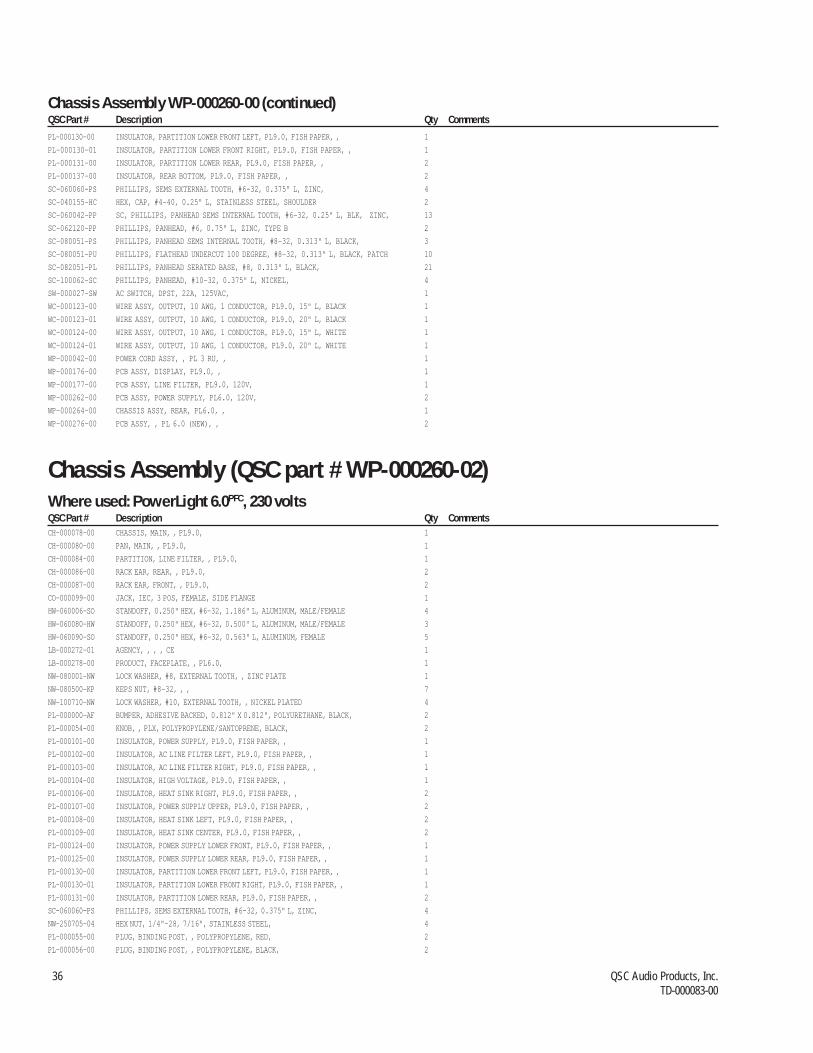
36 QSC Audio Products, Inc.TD-000083-00
PL-000130-00 INSULATOR, PARTITION LOWER FRONT LEFT, PL9.0, FISH PAPER, , 1
PL-000130-01 INSULATOR, PARTITION LOWER FRONT RIGHT, PL9.0, FISH PAPER, , 1
PL-000131-00 INSULATOR, PARTITION LOWER REAR, PL9.0, FISH PAPER, , 2
PL-000137-00 INSULATOR, REAR BOTTOM, PL9.0, FISH PAPER, , 2
SC-060060-PS PHILLIPS, SEMS EXTERNAL TOOTH, #6-32, 0.375" L, ZINC, 4
SC-040155-HC HEX, CAP, #4-40, 0.25" L, STAINLESS STEEL, SHOULDER 2
SC-060042-PP SC, PHILLIPS, PANHEAD SEMS INTERNAL TOOTH, #6-32, 0.25" L, BLK, ZINC, 13
SC-062120-PP PHILLIPS, PANHEAD, #6, 0.75" L, ZINC, TYPE B 2
SC-080051-PS PHILLIPS, PANHEAD SEMS INTERNAL TOOTH, #8-32, 0.313" L, BLACK, 3
SC-080051-PU PHILLIPS, FLATHEAD UNDERCUT 100 DEGREE, #8-32, 0.313" L, BLACK, PATCH 10
SC-082051-PL PHILLIPS, PANHEAD SERATED BASE, #8, 0.313" L, BLACK, 21
SC-100062-SC PHILLIPS, PANHEAD, #10-32, 0.375" L, NICKEL, 4
SW-000027-SW AC SWITCH, DPST, 22A, 125VAC, 1
WC-000123-00 WIRE ASSY, OUTPUT, 10 AWG, 1 CONDUCTOR, PL9.0, 15" L, BLACK 1
WC-000123-01 WIRE ASSY, OUTPUT, 10 AWG, 1 CONDUCTOR, PL9.0, 20" L, BLACK 1
WC-000124-00 WIRE ASSY, OUTPUT, 10 AWG, 1 CONDUCTOR, PL9.0, 15" L, WHITE 1
WC-000124-01 WIRE ASSY, OUTPUT, 10 AWG, 1 CONDUCTOR, PL9.0, 20" L, WHITE 1
WP-000042-00 POWER CORD ASSY, , PL 3 RU, , 1
WP-000176-00 PCB ASSY, DISPLAY, PL9.0, , 1
WP-000177-00 PCB ASSY, LINE FILTER, PL9.0, 120V, 1
WP-000262-00 PCB ASSY, POWER SUPPLY, PL6.0, 120V, 2
WP-000264-00 CHASSIS ASSY, REAR, PL6.0, , 1
WP-000276-00 PCB ASSY, , PL 6.0 (NEW), , 2
Chassis Assembly WP-000260-00 (continued)QSC Part # Description Qty Comments
Chassis Assembly (QSC part # WP-000260-02)Where used: PowerLight 6.0PFC, 230 voltsQSC Part # Description Qty CommentsCH-000078-00 CHASSIS, MAIN, , PL9.0, 1
CH-000080-00 PAN, MAIN, , PL9.0, 1
CH-000084-00 PARTITION, LINE FILTER, , PL9.0, 1
CH-000086-00 RACK EAR, REAR, , PL9.0, 2
CH-000087-00 RACK EAR, FRONT, , PL9.0, 2
CO-000099-00 JACK, IEC, 3 POS, FEMALE, SIDE FLANGE 1
HW-060006-SO STANDOFF, 0.250" HEX, #6-32, 1.186" L, ALUMINUM, MALE/FEMALE 4
HW-060080-HW STANDOFF, 0.250" HEX, #6-32, 0.500" L, ALUMINUM, MALE/FEMALE 3
HW-060090-SO STANDOFF, 0.250" HEX, #6-32, 0.563" L, ALUMINUM, FEMALE 5
LB-000272-01 AGENCY, , , , CE 1
LB-000278-00 PRODUCT, FACEPLATE, , PL6.0, 1
NW-080001-NW LOCK WASHER, #8, EXTERNAL TOOTH, , ZINC PLATE 1
NW-080500-KP KEPS NUT, #8-32, , , 7
NW-100710-NW LOCK WASHER, #10, EXTERNAL TOOTH, , NICKEL PLATED 4
PL-000000-AF BUMPER, ADHESIVE BACKED, 0.812" X 0.812", POLYURETHANE, BLACK, 2
PL-000054-00 KNOB, , PLX, POLYPROPYLENE/SANTOPRENE, BLACK, 2
PL-000101-00 INSULATOR, POWER SUPPLY, PL9.0, FISH PAPER, , 1
PL-000102-00 INSULATOR, AC LINE FILTER LEFT, PL9.0, FISH PAPER, , 1
PL-000103-00 INSULATOR, AC LINE FILTER RIGHT, PL9.0, FISH PAPER, , 1
PL-000104-00 INSULATOR, HIGH VOLTAGE, PL9.0, FISH PAPER, , 1
PL-000106-00 INSULATOR, HEAT SINK RIGHT, PL9.0, FISH PAPER, , 2
PL-000107-00 INSULATOR, POWER SUPPLY UPPER, PL9.0, FISH PAPER, , 2
PL-000108-00 INSULATOR, HEAT SINK LEFT, PL9.0, FISH PAPER, , 2
PL-000109-00 INSULATOR, HEAT SINK CENTER, PL9.0, FISH PAPER, , 2
PL-000124-00 INSULATOR, POWER SUPPLY LOWER FRONT, PL9.0, FISH PAPER, , 1
PL-000125-00 INSULATOR, POWER SUPPLY LOWER REAR, PL9.0, FISH PAPER, , 1
PL-000130-00 INSULATOR, PARTITION LOWER FRONT LEFT, PL9.0, FISH PAPER, , 1
PL-000130-01 INSULATOR, PARTITION LOWER FRONT RIGHT, PL9.0, FISH PAPER, , 1
PL-000131-00 INSULATOR, PARTITION LOWER REAR, PL9.0, FISH PAPER, , 2
SC-060060-PS PHILLIPS, SEMS EXTERNAL TOOTH, #6-32, 0.375" L, ZINC, 4
NW-250705-04 HEX NUT, 1/4"-28, 7/16", STAINLESS STEEL, 4
PL-000055-00 PLUG, BINDING POST, , POLYPROPYLENE, RED, 2
PL-000056-00 PLUG, BINDING POST, , POLYPROPYLENE, BLACK, 2

PowerLight 9.0PFC, PowerLight 6.0PFC, PowerLight 6.0 II Service Manual 37Parts lists
PL-000137-00 INSULATOR, REAR BOTTOM, PL9.0, FISH PAPER, , 2
SC-040155-HC HEX, CAP, #4-40, 0.25" L, STAINLESS STEEL, SHOULDER 2
SC-060042-PP SC, PHILLIPS, PANHEAD SEMS INTERNAL TOOTH, #6-32, 0.25" L, BLK, ZINC, 13
SC-062120-PP PHILLIPS, PANHEAD, #6, 0.75" L, ZINC, TYPE B 2
SC-080051-PS PHILLIPS, PANHEAD SEMS INTERNAL TOOTH, #8-32, 0.313" L, BLACK, 3
SC-080051-PU PHILLIPS, FLATHEAD UNDERCUT 100 DEGREE, #8-32, 0.313" L, BLACK, PATCH 10
SC-082051-PL PHILLIPS, PANHEAD SERATED BASE, #8, 0.313" L, BLACK, 21
SC-083061-PU PHILLIPS, FLATHEAD UNDERCUT, #8, 0.375" L, BLACK WAXED, TYPE B 2
SC-100062-SC PHILLIPS, PANHEAD, #10-32, 0.375" L, NICKEL, 4
SW-000027-SW AC SWITCH, DPST, 22A, 125VAC, 1
WC-000022-00 AC CORD, IEC, 16 AWG, 3 CONDUCTOR, , 2.5 METERS, 250 VAC 1
WC-000123-00 WIRE ASSY, OUTPUT, 10 AWG, 1 CONDUCTOR, PL9.0, 15" L, BLACK 1
WC-000123-01 WIRE ASSY, OUTPUT, 10 AWG, 1 CONDUCTOR, PL9.0, 20" L, BLACK 1
WC-000124-00 WIRE ASSY, OUTPUT, 10 AWG, 1 CONDUCTOR, PL9.0, 15" L, WHITE 1
WC-000124-01 WIRE ASSY, OUTPUT, 10 AWG, 1 CONDUCTOR, PL9.0, 20" L, WHITE 1
WC-000135-00 CABLE ASSY, IEC/AC FILTER, 12 AWG, 3 CONDUCTOR, PL9.0, 5" L, 1
WP-000176-00 PCB ASSY, DISPLAY, PL9.0, , 1
WP-000181-00 PCB ASSY, LINE FILTER, PL9.0, 230V, 1
WP-000262-02 PCB ASSY, POWER SUPPLY, PL6.0, 230V, 2
WP-000264-00 CHASSIS ASSY, REAR, PL6.0, , 1
WP-000276-00 PCB ASSY, , PL 6.0 (NEW), , 2
Chassis Assembly WP-000260-02 (continued)QSC Part # Description Qty Comments Ref erence
Chassis Assembly (QSC part # WP-000170-00)Where used: PowerLight 9.0PFC, 120 voltsQSC Part # Description Qty CommentsCH-000078-00 CHASSIS, MAIN, , PL9.0, 1
CH-000080-00 PAN, MAIN, , PL9.0, 1
CH-000084-00 PARTITION, LINE FILTER, , PL9.0, 1
CH-000086-00 RACK EAR, REAR, , PL9.0, 2
CH-000087-00 RACK EAR, FRONT, , PL9.0, 2
HW-060006-SO STANDOFF, 0.250" HEX, #6-32, 1.186" L, ALUMINUM, MALE/FEMALE 4
HW-060080-HW STANDOFF, 0.250" HEX, #6-32, 0.500" L, ALUMINUM, MALE/FEMALE 3
HW-060090-SO STANDOFF, 0.250" HEX, #6-32, 0.563" L, ALUMINUM, FEMALE 5
LB-000052-00 AGENCY, LISTING, , , UL/CUL 1
LB-000217-00 PRODUCT, FACEPLATE, , PL9.0, 1
NW-000021-03 FLAT WASHER, 1.14", , ALUMINUM, BLACK ANODIZED 1
NW-080001-NW LOCK WASHER, #8, EXTERNAL TOOTH, , ZINC PLATE 1
NW-080500-KP KEPS NUT, #8-32, , , 7
NW-100710-NW LOCK WASHER, #10, EXTERNAL TOOTH, , NICKEL PLATED 4
NW-250705-04 HEX NUT, 1/4"-28, 7/16", STAINLESS STEEL, 4
PL-000000-AF BUMPER, ADHESIVE BACKED, 0.812" X 0.812", POLYURETHANE, BLACK, 2
PL-000054-00 KNOB, , PLX, POLYPROPYLENE/SANTOPRENE, BLACK, 2
PL-000101-00 INSULATOR, POWER SUPPLY, PL9.0, FISH PAPER, , 1
PL-000102-00 INSULATOR, AC LINE FILTER LEFT, PL9.0, FISH PAPER, , 1
PL-000103-00 INSULATOR, AC LINE FILTER RIGHT, PL9.0, FISH PAPER, , 1
PL-000104-00 INSULATOR, HIGH VOLTAGE, PL9.0, FISH PAPER, , 1
PL-000106-00 INSULATOR, HEAT SINK RIGHT, PL9.0, FISH PAPER, , 2
PL-000107-00 INSULATOR, POWER SUPPLY UPPER, PL9.0, FISH PAPER, , 2
PL-000108-00 INSULATOR, HEAT SINK LEFT, PL9.0, FISH PAPER, , 2
PL-000109-00 INSULATOR, HEAT SINK CENTER, PL9.0, FISH PAPER, , 2
PL-000124-00 INSULATOR, POWER SUPPLY LOWER FRONT, PL9.0, FISH PAPER, , 1
PL-000125-00 INSULATOR, POWER SUPPLY LOWER REAR, PL9.0, FISH PAPER, , 1
PL-000130-00 INSULATOR, PARTITION LOWER FRONT LEFT, PL9.0, FISH PAPER, , 1
PL-000130-01 INSULATOR, PARTITION LOWER FRONT RIGHT, PL9.0, FISH PAPER, , 1
PL-000131-00 INSULATOR, PARTITION LOWER REAR, PL9.0, FISH PAPER, , 2
PL-000137-00 INSULATOR, REAR BOTTOM, PL9.0, FISH PAPER, , 2
SC-040155-HC HEX, CAP, #4-40, 0.25" L, STAINLESS STEEL, SHOULDER 2
SC-060042-PP SC, PHILLIPS, PANHEAD SEMS INTERNAL TOOTH, #6-32, 0.25" L, BLK, ZINC, 13
SC-060060-PS PHILLIPS, SEMS EXTERNAL TOOTH, #6-32, 0.375" L, ZINC, 4
SC-062120-PP PHILLIPS, PANHEAD, #6, 0.75" L, ZINC, TYPE B 2

38 QSC Audio Products, Inc.TD-000083-00
SC-080051-PS PHILLIPS, PANHEAD SEMS INTERNAL TOOTH, #8-32, 0.313" L, BLACK, 3
SC-080051-PU PHILLIPS, FLATHEAD UNDERCUT 100 DEGREE, #8-32, 0.313" L, BLACK, PATCH 10
SC-082051-PL PHILLIPS, PANHEAD SERATED BASE, #8, 0.313" L, BLACK, 21
SC-100062-SC PHILLIPS, PANHEAD, #10-32, 0.375" L, NICKEL, 4
SW-000027-SW AC SWITCH, DPST, 22A, 125VAC, 1
WC-000123-00 WIRE ASSY, OUTPUT, 10 AWG, 1 CONDUCTOR, PL9.0, 15" L, BLACK 1
WC-000123-01 WIRE ASSY, OUTPUT, 10 AWG, 1 CONDUCTOR, PL9.0, 20" L, BLACK 1
WC-000124-00 WIRE ASSY, OUTPUT, 10 AWG, 1 CONDUCTOR, PL9.0, 15" L, WHITE 1
WC-000124-01 WIRE ASSY, OUTPUT, 10 AWG, 1 CONDUCTOR, PL9.0, 20" L, WHITE 1
WP-000042-00 POWER CORD ASSY, , PL 3 RU, , 1
WP-000172-00 CHASSIS ASSY, REAR, PL9.0, , 1
WP-000173-00 PCB ASSY, POWER SUPPLY, PL9.0, 120V, 2
WP-000176-00 PCB ASSY, DISPLAY, PL9.0, , 1
WP-000177-00 PCB ASSY, LINE FILTER, PL9.0, 120V, 1
WP-000182-00 PCB ASSY, , PL 9.0 (NEW), , 2
Chassis Assembly WP-000170-00 (continued)QSC Part # Description Qty Comments
Chassis Assembly (QSC part # WP-000170-02)Where used: PowerLight 9.0PFC, 230 voltsQSC Part # Description Qty CommentsCH-000078-00 CHASSIS, MAIN, , PL9.0, 1
CH-000080-00 PAN, MAIN, , PL9.0, 1
CH-000084-00 PARTITION, LINE FILTER, , PL9.0, 1
CH-000086-00 RACK EAR, REAR, , PL9.0, 2
CH-000087-00 RACK EAR, FRONT, , PL9.0, 2
CO-000099-00 JACK, IEC, 3 POS, FEMALE, SIDE FLANGE 1
HW-060006-SO STANDOFF, 0.250" HEX, #6-32, 1.186" L, ALUMINUM, MALE/FEMALE 4
HW-060080-HW STANDOFF, 0.250" HEX, #6-32, 0.500" L, ALUMINUM, MALE/FEMALE 3
HW-060090-SO STANDOFF, 0.250" HEX, #6-32, 0.563" L, ALUMINUM, FEMALE 5
LB-000217-00 PRODUCT, FACEPLATE, , PL9.0, 1
LB-000272-00 AGENCY, VOLTAGE, , , CE 1
NW-080001-NW LOCK WASHER, #8, EXTERNAL TOOTH, , ZINC PLATE 1
NW-080500-KP KEPS NUT, #8-32, , , 7
NW-100710-NW LOCK WASHER, #10, EXTERNAL TOOTH, , NICKEL PLATED 4
NW-250705-04 HEX NUT, 1/4"-28, 7/16", STAINLESS STEEL, 4
PL-000000-AF BUMPER, ADHESIVE BACKED, 0.812" X 0.812", POLYURETHANE, BLACK, 2
PL-000054-00 KNOB, , PLX, POLYPROPYLENE/SANTOPRENE, BLACK, 2
PL-000055-00 PLUG, BINDING POST, , POLYPROPYLENE, RED, 2
PL-000056-00 PLUG, BINDING POST, , POLYPROPYLENE, BLACK, 2
PL-000101-00 INSULATOR, POWER SUPPLY, PL9.0, FISH PAPER, , 1
PL-000102-00 INSULATOR, AC LINE FILTER LEFT, PL9.0, FISH PAPER, , 1
PL-000103-00 INSULATOR, AC LINE FILTER RIGHT, PL9.0, FISH PAPER, , 1
PL-000104-00 INSULATOR, HIGH VOLTAGE, PL9.0, FISH PAPER, , 1
PL-000106-00 INSULATOR, HEAT SINK RIGHT, PL9.0, FISH PAPER, , 2
PL-000107-00 INSULATOR, POWER SUPPLY UPPER, PL9.0, FISH PAPER, , 2
PL-000108-00 INSULATOR, HEAT SINK LEFT, PL9.0, FISH PAPER, , 2
PL-000109-00 INSULATOR, HEAT SINK CENTER, PL9.0, FISH PAPER, , 2
PL-000124-00 INSULATOR, POWER SUPPLY LOWER FRONT, PL9.0, FISH PAPER, , 1
PL-000125-00 INSULATOR, POWER SUPPLY LOWER REAR, PL9.0, FISH PAPER, , 1
PL-000130-00 INSULATOR, PARTITION LOWER FRONT LEFT, PL9.0, FISH PAPER, , 1
PL-000130-01 INSULATOR, PARTITION LOWER FRONT RIGHT, PL9.0, FISH PAPER, , 1
PL-000131-00 INSULATOR, PARTITION LOWER REAR, PL9.0, FISH PAPER, , 2
PL-000137-00 INSULATOR, REAR BOTTOM, PL9.0, FISH PAPER, , 2
SC-060060-PS PHILLIPS, SEMS EXTERNAL TOOTH, #6-32, 0.375" L, ZINC, 4
SC-040155-HC HEX, CAP, #4-40, 0.25" L, STAINLESS STEEL, SHOULDER 2
SC-060042-PP SC, PHILLIPS, PANHEAD SEMS INTERNAL TOOTH, #6-32, 0.25" L, BLK, ZINC, 13
SC-062120-PP PHILLIPS, PANHEAD, #6, 0.75" L, ZINC, TYPE B 2
SC-080051-PS PHILLIPS, PANHEAD SEMS INTERNAL TOOTH, #8-32, 0.313" L, BLACK, 3
SC-080051-PU PHILLIPS, FLATHEAD UNDERCUT 100 DEGREE, #8-32, 0.313" L, BLACK, PATCH 10
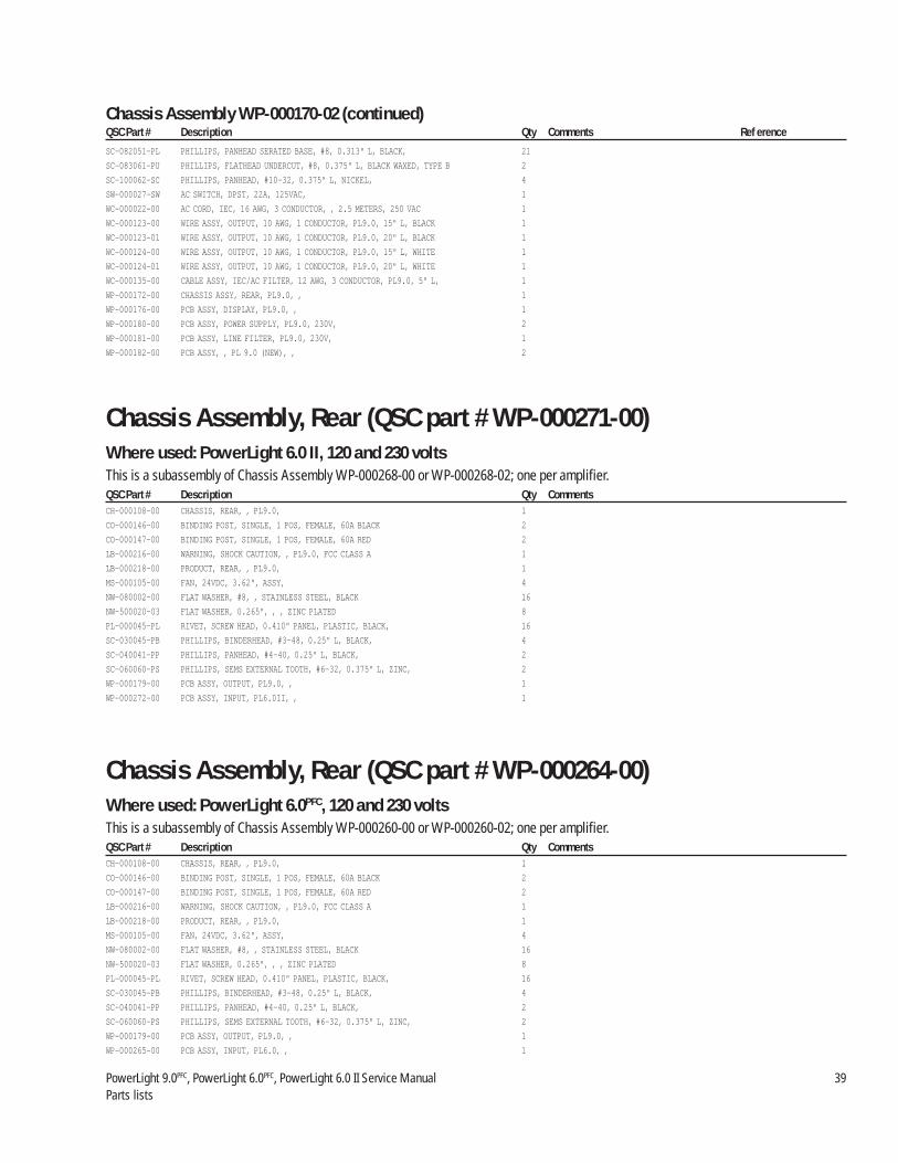
PowerLight 9.0PFC, PowerLight 6.0PFC, PowerLight 6.0 II Service Manual 39Parts lists
SC-082051-PL PHILLIPS, PANHEAD SERATED BASE, #8, 0.313" L, BLACK, 21
SC-083061-PU PHILLIPS, FLATHEAD UNDERCUT, #8, 0.375" L, BLACK WAXED, TYPE B 2
SC-100062-SC PHILLIPS, PANHEAD, #10-32, 0.375" L, NICKEL, 4
SW-000027-SW AC SWITCH, DPST, 22A, 125VAC, 1
WC-000022-00 AC CORD, IEC, 16 AWG, 3 CONDUCTOR, , 2.5 METERS, 250 VAC 1
WC-000123-00 WIRE ASSY, OUTPUT, 10 AWG, 1 CONDUCTOR, PL9.0, 15" L, BLACK 1
WC-000123-01 WIRE ASSY, OUTPUT, 10 AWG, 1 CONDUCTOR, PL9.0, 20" L, BLACK 1
WC-000124-00 WIRE ASSY, OUTPUT, 10 AWG, 1 CONDUCTOR, PL9.0, 15" L, WHITE 1
WC-000124-01 WIRE ASSY, OUTPUT, 10 AWG, 1 CONDUCTOR, PL9.0, 20" L, WHITE 1
WC-000135-00 CABLE ASSY, IEC/AC FILTER, 12 AWG, 3 CONDUCTOR, PL9.0, 5" L, 1
WP-000172-00 CHASSIS ASSY, REAR, PL9.0, , 1
WP-000176-00 PCB ASSY, DISPLAY, PL9.0, , 1
WP-000180-00 PCB ASSY, POWER SUPPLY, PL9.0, 230V, 2
WP-000181-00 PCB ASSY, LINE FILTER, PL9.0, 230V, 1
WP-000182-00 PCB ASSY, , PL 9.0 (NEW), , 2
Chassis Assembly WP-000170-02 (continued)QSC Part # Description Qty Comments Ref erence
Chassis Assembly, Rear (QSC part # WP-000271-00)Where used: PowerLight 6.0 II, 120 and 230 voltsThis is a subassembly of Chassis Assembly WP-000268-00 or WP-000268-02; one per amplifier.QSC Part # Description Qty CommentsCH-000108-00 CHASSIS, REAR, , PL9.0, 1
CO-000146-00 BINDING POST, SINGLE, 1 POS, FEMALE, 60A BLACK 2
CO-000147-00 BINDING POST, SINGLE, 1 POS, FEMALE, 60A RED 2
LB-000216-00 WARNING, SHOCK CAUTION, , PL9.0, FCC CLASS A 1
LB-000218-00 PRODUCT, REAR, , PL9.0, 1
MS-000105-00 FAN, 24VDC, 3.62", ASSY, 4
NW-080002-00 FLAT WASHER, #8, , STAINLESS STEEL, BLACK 16
NW-500020-03 FLAT WASHER, 0.265", , , ZINC PLATED 8
PL-000045-PL RIVET, SCREW HEAD, 0.410" PANEL, PLASTIC, BLACK, 16
SC-030045-PB PHILLIPS, BINDERHEAD, #3-48, 0.25" L, BLACK, 4
SC-040041-PP PHILLIPS, PANHEAD, #4-40, 0.25" L, BLACK, 2
SC-060060-PS PHILLIPS, SEMS EXTERNAL TOOTH, #6-32, 0.375" L, ZINC, 2
WP-000179-00 PCB ASSY, OUTPUT, PL9.0, , 1
WP-000272-00 PCB ASSY, INPUT, PL6.0II, , 1
Chassis Assembly, Rear (QSC part # WP-000264-00)Where used: PowerLight 6.0PFC, 120 and 230 voltsThis is a subassembly of Chassis Assembly WP-000260-00 or WP-000260-02; one per amplifier.QSC Part # Description Qty CommentsCH-000108-00 CHASSIS, REAR, , PL9.0, 1
CO-000146-00 BINDING POST, SINGLE, 1 POS, FEMALE, 60A BLACK 2
CO-000147-00 BINDING POST, SINGLE, 1 POS, FEMALE, 60A RED 2
LB-000216-00 WARNING, SHOCK CAUTION, , PL9.0, FCC CLASS A 1
LB-000218-00 PRODUCT, REAR, , PL9.0, 1
MS-000105-00 FAN, 24VDC, 3.62", ASSY, 4
NW-080002-00 FLAT WASHER, #8, , STAINLESS STEEL, BLACK 16
NW-500020-03 FLAT WASHER, 0.265", , , ZINC PLATED 8
PL-000045-PL RIVET, SCREW HEAD, 0.410" PANEL, PLASTIC, BLACK, 16
SC-030045-PB PHILLIPS, BINDERHEAD, #3-48, 0.25" L, BLACK, 4
SC-040041-PP PHILLIPS, PANHEAD, #4-40, 0.25" L, BLACK, 2
SC-060060-PS PHILLIPS, SEMS EXTERNAL TOOTH, #6-32, 0.375" L, ZINC, 2
WP-000179-00 PCB ASSY, OUTPUT, PL9.0, , 1
WP-000265-00 PCB ASSY, INPUT, PL6.0, , 1

40 QSC Audio Products, Inc.TD-000083-00
Chassis Assembly, Rear (QSC Part # WP-000172-00)Where used: PL9.0PFC, 120 and 230 volts.This is a subassembly of Chassis Assembly WP-000170-00 or WP-000170-02; one per amplifier.QSC Part # Description Qty CommentsCO-000146-00 BINDING POST, SINGLE, 1 POS, FEMALE, 60A BLACK 2
CO-000147-00 BINDING POST, SINGLE, 1 POS, FEMALE, 60A RED 2
CH-000108-00 CHASSIS, REAR, , PL9.0, 1
LB-000216-00 WARNING, SHOCK CAUTION, , PL9.0, FCC CLASS A 1
LB-000218-00 PRODUCT, REAR, , PL9.0, 1
MS-000105-00 FAN, 24VDC, 3.62", ASSY, 4
NW-080002-00 FLAT WASHER, #8, , STAINLESS STEEL, BLACK 16
NW-500020-03 FLAT WASHER, 0.265", , , ZINC PLATED 8
PL-000045-PL RIVET, SCREW HEAD, 0.410" PANEL, PLASTIC, BLACK, 16
SC-030045-PB PHILLIPS, BINDERHEAD, #3-48, 0.25" L, BLACK, 4
SC-040041-PP PHILLIPS, PANHEAD, #4-40, 0.25" L, BLACK, 2
SC-060060-PS PHILLIPS, SEMS EXTERNAL TOOTH, #6-32, 0.375" L, ZINC, 2
WP-000175-00 PCB ASSY, INPUT, PL9.0, , 1
WP-000179-00 PCB ASSY, OUTPUT, PL9.0, , 1
Input PCB Assembly (QSC part # WP-000272-00)Where used: PowerLight 6.0 II, 120 and 230 volts.This is a subassembly of the Chassis Assembly, Rear (WP-000271-00); one per amplifier.QSC Part # Description Qty Comments ReferenceCA-122001-10 220PF, 10 PCNT, 100V, CERAMIC NPO, DISC, 4 C300, C302, C400, C402
CA-410004-10 0.1UF, 20 PCNT, 50V, CERAMIC Z5U, DIPPED, 4 C301, C303, C401, C403
CO-000168-00 XLR, COMBO, 3 POS, FEMALE, VERTICAL 2 J301, J401
IC-000072-OP OPAMP, DUAL, TL072, , 2 U300, U400
PC-000175-00 INPUT, PL9.0, , 1
QD-000062-10 TRANSISTOR NPN, 40V, 0.2A, 1.5W, 2N3904, TO-92, 1 Q1
QD-001340-LR LED RED, , , , , T-1 3/4, VOLTAGE REFERENCE 2 FLUSH TO THE PCB, CUT & CLINCH BOTH LEADS, AVOID TRACES LD1, LD2
QD-004148-DX DIODE, 75V, 0.075A, , 1N4148, DO-35, 4NS 2 D1, D2
RE-003305-BC 33, 5 PCNT, 1/4W, CARBON FILM, , 1 R10
RE-004751-BM 47.5, 1 PCNT, 1/4W, METAL FILM, , 3 R13, R306, R406
RE-110001-10 1.00K, 1 PCNT, 1/3W, METAL FILM, , 8 R300–R303, R400–R403
RE-134802-10 3.48K, 1 PCNT, 1/8W, METAL FILM, , 4 R1–R3, R22
RE-151100-10 5.11K, 1/4W, 1 PCNT, METAL FILM, , 1 R12
RE-190901-BM 9.09K, 1 PCNT, 1/4W, METAL FILM, , 5 R4, R304, R305, R404,R405
RE-220001-10 20.0K, 1 PCNT, 1/3W, METAL FILM, , 2 R20, R23
SW-000043-00 SWITCH, 4P3T, SLIDE, PCB MOUNT 1 SW1
WC-000128-00 RIBBON CABLE ASSY, , 28 AWG, 16 CONDUCTOR, PL9.0, 8.75" L, 2
WP-000178-00 PCB ASSY, INPUT DAUGHTER, PL6.0/PL9.0, , 1
Output PCB Assembly (QSC part # WP-000179-00)Where used: All models, 120 or 230 volts.This is a subassembly of the Chassis Assembly, Rear (WP-000271-00, WP-000264-00, or WP-000172-00); one per amplifier.QSC Part # Description Qty CommentsCA-410009-00 0.1UF, 5 PCNT, 250V, FILM, WRAPPED, 2 USE .050 SPACER
CO-000036-CO JACK, SPEAKON, 4 POS, FEMALE, 2
PC-000179-00 OUTPUT, PL9.0, , 1 APPLY MASKING DOTS 8 PLACES FOR BINDING POST, AND E1

PowerLight 9.0PFC, PowerLight 6.0PFC, PowerLight 6.0 II Service Manual 41Parts lists
Input PCB Assembly (QSC part # WP-000175-00)Where used: PowerLight 6.0PFC, 120 and 230 volts.This is a subassembly of the Chassis Assembly, Rear (WP-000179-00); one per amplifier.QSC Part # Description Qty Comments ReferenceCA-122001-10 220PF, 10 PCNT, 100V, CERAMIC NPO, DISC, 4 C300, C302, C400, C402
CA-410004-10 0.1UF, 20 PCNT, 50V, CERAMIC Z5U, DIPPED, 4 C301, C303, C401, C403
CO-000168-00 XLR, COMBO, 3 POS, FEMALE, VERTICAL 2 J301, J401
IC-000072-OP OPAMP, DUAL, TL072, , 2 U300, U400
PC-000175-00 INPUT, PL9.0, , 1
QD-000062-10 TRANSISTOR NPN, 40V, 0.2A, 1.5W, 2N3904, TO-92, 1 Q1
QD-001340-LR LED RED, , , , , T-1 3/4, VOLTAGE REFERENCE 2 FLUSH TO THE PCB, CUT & CLINCH BOTH LEADS, AVOID TRACES LD1, LD2
QD-004148-DX DIODE, 75V, 0.075A, , 1N4148, DO-35, 4NS 2 D1, D2
RE-003305-BC 33, 5 PCNT, 1/4W, CARBON FILM, , 1 R10
RE-004751-BM 47.5, 1 PCNT, 1/4W, METAL FILM, , 3 R13, R306, R406
RE-084501-10 845, 1 PCNT, 1/4W, METAL FILM, , 1 R12
RE-110001-10 1.00K, 1 PCNT, 1/3W, METAL FILM, , 8 R300–R303, R400–R403
RE-134802-10 3.48K, 1 PCNT, 1/8W, METAL FILM, , 4 R1, R2, R3, R22
RE-190901-BM 9.09K, 1 PCNT, 1/4W, METAL FILM, , 5 R4, R304, R305, R404,R405
RE-220001-10 20.0K, 1 PCNT, 1/3W, METAL FILM, , 2 R20, R23
SW-000043-00 SWITCH, 4P3T, SLIDE, PCB MOUNT 1 SW1
WC-000128-00 RIBBON CABLE ASSY, , 28 AWG, 16 CONDUCTOR, PL9.0, 8.75" L, 2
WP-000178-00 PCB ASSY, INPUT DAUGHTER, PL6.0/PL9.0, , 1
Input PCB Assembly (QSC part # WP-000265-00)Where used: PowerLight 6.0PFC, 120 and 230 volts.This is a subassembly of the Chassis Assembly, Rear (WP-000264-00); one per amplifier.QSC Part # Description Qty Comments ReferenceCA-122001-10 220PF, 10 PCNT, 100V, CERAMIC NPO, DISC, 4 C300, C302, C400, C402
CA-410004-10 0.1UF, 20 PCNT, 50V, CERAMIC Z5U, DIPPED, 4 C301, C303, C401, C403
CO-000168-00 XLR, COMBO, 3 POS, FEMALE, VERTICAL 2 J301, J401
IC-000072-OP OPAMP, DUAL, TL072, , 2 U300, U400
PC-000175-00 INPUT, PL9.0, , 1
QD-000062-10 TRANSISTOR NPN, 40V, 0.2A, 1.5W, 2N3904, TO-92, 1 Q1
QD-001340-LR LED RED, , , , , T-1 3/4, VOLTAGE REFERENCE 2 FLUSH TO THE PCB, CUT & CLINCH BOTH LEADS, AVOID TRACES LD1, LD2
QD-004148-DX DIODE, 75V, 0.075A, , 1N4148, DO-35, 4NS 2 D1, D2
RE-003305-BC 33, 5 PCNT, 1/4W, CARBON FILM, , 1 R10
RE-004751-BM 47.5, 1 PCNT, 1/4W, METAL FILM, , 3 R13, R306, R406
RE-110001-10 1.00K, 1 PCNT, 1/3W, METAL FILM, , 8 R300–R303, R400–R403
RE-122601-10 2.26K, 1 PCNT, 1/4W, METAL FILM, , 1 R12
RE-134802-10 3.48K, 1 PCNT, 1/8W, METAL FILM, , 4 R1, R2, R3, R22
RE-190901-BM 9.09K, 1 PCNT, 1/4W, METAL FILM, , 5 R4, R304, R305, R404,R405
RE-220001-10 20.0K, 1 PCNT, 1/3W, METAL FILM, , 2 R20, R23
SW-000043-00 SWITCH, 4P3T, SLIDE, PCB MOUNT 1 SW1
WC-000128-00 RIBBON CABLE ASSY, , 28 AWG, 16 CONDUCTOR, PL9.0, 8.75" L, 2
WP-000178-00 PCB ASSY, INPUT DAUGHTER, PL6.0/PL9.0, , 1

42 QSC Audio Products, Inc.TD-000083-00
Input Daughterboard Assembly (QSC part # WP-000178-00)Where used: PowerLight 6.0PFC and PowerLight 9.0PFC, 120 and 230 volts.This is a subassembly of the Input PCB Assembly (WP-000265-00 or WP-000175-00); one per amplifier.QSC Part # Description Qty Comments ReferenceCA-122001-10 220PF, 10 PCNT, 100V, CERAMIC NPO, DISC, 1 C1
CA-322002-10 0.022UF, 5 PCNT, 50V, FILM, DIPPED, 2 C2, C4
CO-000084-00 HEADER, 0.1" CENTERS, 12 POS (1X12), MALE, TERMINAL STRIP RIGHT ANGLE 2 J1A, J2A
CO-000106-00 JACK, HD15, 15 POS, FEMALE, RIGHT ANGLE SWAGED JACK SCREW 1 REF: J33 J5
CO-000119-00 JACK, EURO, 2 POS, FEMALE, GREEN 1 J6
CO-000120-00 JACK, EURO, 3 POS, FEMALE, GREEN 2 J3, J4
HW-040001-00 BRACKET, ANGLE, #4-40, 0.375" L, ZINC PLATED STEEL, 2
PC-000178-00 INPUT DAUGHTER, PL9.0, , 1 MASK J1A, J2A
QD-004148-DX DIODE, 75V, 0.075A, , 1N4148, DO-35, 4NS 1 D1
SC-040041-PP PHILLIPS, PANHEAD, #4-40, 0.25" L, BLACK, 2
Audio Channel Module Assembly (QSC part number WP-000276-00)Where used: PowerLight 6.0 II and PowerLight 6.0PFC, both 120 and 230 volts.This is a subassembly of the chassis assembly; two per amplifier.QSC Part # Description Qty Comments ReferenceCA-027001-30 27PF, 5 PCNT, 50V, CERAMIC NPO, 0805, 3 C52, C128, C134
CA-027002-30 27PF, 5 PCNT, 250V, CERAMIC NPO, 1206, 3 C15, C35, C51
CA-033001-30 33PF, 5 PCNT, 100V, CERAMIC NPO, 0805, 8 C84, C139, C140, C143–C147
CA-110002-30 100PF, 5 PCNT, 50V, CERAMIC NPO, 0805, 6 C93, C99, C109, C112,C113, C116
CA-118000-30 180PF, 5 PCNT, 100V, CERAMIC NPO, 0805, 1 C50
CA-122002-30 220PF, 5 PCNT, 50V, CERAMIC NPO, 0805, 2 C54, C124
CA-130000-30 300PF, 5 PCNT, 50V, CERAMIC NPO, 0805, 1 C130
CA-133002-30 330PF, 5 PCNT, 50V, CERAMIC NPO, 0805, 5 C115, C132, C133, C730,C732
CA-147004-30 470PF, 5 PCNT, 50V, CERAMIC NPO, 0805, 4 C32, C43, C46, C58
CA-168003-30 680PF, 5 PCNT, 50V, CERAMIC NPO, 0805, 1 C713
CA-310001-10 0.01UF, 10 PCNT, 100V, FILM, DIPPED, 1 C745
CA-310004-30 0.01UF, 10 PCNT, 50V, CERAMIC X7R, 1206, 3 C81, C709, C710
CA-322005-30 0.022UF, 5 PCNT, 250V, FILM, 2220, 5 C725–C727, C740, C741
CA-410006-30 0.1UF, 10 PCNT, 50V, CERAMIC X7R, 1206, 68 C3–C5, C10, C17, C18,C21, C22, C29, C36–C38,C40, C42, C47, C60, C82,C83, C90, C91, C94, C96,C97, C100, C104, C106,C110, C118–C120, C122,C123, C136, C137, C708,C711, C712, C720–C722,C728, C733–C737, C744
CA-410009-00 0.1UF, 5 PCNT, 250V, FILM, WRAPPED, 4 USE .050 SPACER THIS PART HAS TWO DIFFERENT PREP C64–C67
CA-410009-00 0.1UF, 5 PCNT, 250V, FILM, WRAPPED, 2 USE .050 SPACER (PREP BY HAND AT VERTICAL POSITION) THIS PART HASTWO DIFFERENT PREP C723, C724
CA-447006-30 0.47UF, 20 PCNT, 25V, TANTALUM, 3216, 6 C34, C39, C44, C92,C102, C103
CA-510004-30 1.0UF, 20 PCNT, 50V, CERAMIC Z5U, 1210, 5 C14, C714, C717–C719
CA-610005-30 10UF, 20 PCNT, 35V, TANTALUM, SMT, 10 C2, C8, C11–C13, C16,C20, C27, C101, C105
CA-610008-30 10UF, 20 PCNT, 20V, TANTALUM, 6032, 8 C70–C77
CA-622002-30 22UF, 20 PCNT, 25V, TANTALUM, SMT, 18 C6, C7, C19, C30, C31,C33, C48, C49, C55, C62,C63, C68, C107, C111,C117, C125, C126, C129
CA-633001-00 33UF, 20 PCNT, 400V, ELECTROLYTIC, , 1 USE .050 SPACER C1
CA-647003-10 47UF, 10 PCNT, 10V, ELECTROLYTIC, , NON-POLAR LOW PROFILE 10 C28, C88, C89, C98,C108, C114, C121, C127,C131, C742
CA-710001-10 100UF, 20 PCNT, 35V, ELECTROLYTIC, , 1 C59
CA-922002-00 22000UF, 20 PCNT, 50V, ELECTROLYTIC, , 4 C9, C26, C41, C57

PowerLight 9.0PFC, PowerLight 6.0PFC, PowerLight 6.0 II Service Manual 43Parts lists
CH-000091-00 CLAMP, TO-264, 5.1", PL9.0, 2
CH-000091-01 CLAMP, TO-264, 4.5", PL9.0, 3
CH-000074-00 HEAT SINK, AUDIO, 8", PL9.0, 3
CH-000075-00 HEAT SINK, AUDIO, 14", PL9.0, 1
CO-000074-00 HEADER, 0.1" CENTERS, 8 POS (1X8), MALE, RAMP LOCK 1 J4
CO-000033-CO HEADER, 0.1" CENTERS, 4 POS (1X4), MALE, RAMP LOCK 1 J5
CO-000056-CO HEADER, 0.1" CENTERS, 16 POS (2X8), MALE, LATCHING BOX 1 J7
CO-000124-00 BARRIER STRIP, 0.375" CENTERS, 5 POS, , SHORT PIN 1 J3
HW-080005-SO SPACER, 0.312" ROUND, #8, 0.187" L, BRASS, SWAGE 4
HW-080008-SO SPACER, 0.312" ROUND, #8, 0.187" L, ALUMINUM, SWAGE 11
IC-000046-30 OPAMP, DUAL, TLO72, SMT, 10 U2, U5, U6, U9, U15,U17, U19, U20, U22, U23
IC-000047-30 COMPARATOR, DUAL, LM393, SMT, 2 U7, U8
IC-000048-30 OPAMP, DUAL, MC33078, , 1 U18
IC-000059-00 TOP SWITCH, , TOP202, , 1 U3
IC-000067-30 DIFFERENTIAL AMPLIFIER, DUAL, CA3054, SMT, 5 U21, U24–U26, U28
IC-000070-30 VOLTAGE REFERENCE, +2.5V, LM4040DIM3X-2.5, , 1 U1
IC-000071-00 SENSOR, TEMPERATURE, LM35DZ, , 1 U10
IC-000073-30 TRANSCONDUCTANCE OPAMP, DUAL, LM13600M, , 1 U16
MS-000102-00 SHIELD, ELECTRO-MAGNETIC, INSULATED, PL9.0, 1
NW-100300-00 PRESS-IN NUT, #10-32, , , 2
PC-000182-00 PCB MAIN, PL 9.0, , 1
PL-000091-00 INSULATOR, STEP SWITCH, PL9.0, THERMALLY CONDUCTIVE, , 1
PL-000092-00 ISOLATOR, SPRING, PL9.0, FR-4 PCB, , 1
PL-000094-00 INSULATOR, CAPACITOR, PL9.0, FISH PAPER, , 1
PL-000112-00 RIVET, , 0.156" X 0.322", PLASTIC, , 1
PL-000121-00 SPACER, LED/TO-92, 0.18", PVC, BLACK, 1
PL-905156-SP SPACER, ROUND, 0.047"ID X 0.25"OD X 0.155"L, NYLON, , 6
PL-905385-SP SPACER, ROUND, 0.047"ID X 0.25"OD X 0.385"L, NYLON, , 1
PT-250000-AT TRIM, 5K, 20 PCNT, 0.15W, , 1 VR1
QD-000024-QD DIODE ZENER, 6.2V, , 0.25W, DZ901116G, DO-35, 3 D96–D98
QD-000062-10 TRANSISTOR NPN, 40V, 0.2A, 1.5W, 2N3904, TO-92, 1 Q700
QD-000063-10 TRANSISTOR PNP, 40V, 0.2A, 1.5W, 2N3906, TO-92, 1 Q701
QD-000065-10 TRANSISTOR PNP, 300V, 0.5A, 1.5W, MPSA92, TO-92, 3 Q23, Q83, Q88
QD-000078-10 TRANSISTOR NPN DARLINGTON, 30V, 0.5A, 1.5W, MPSA13, TO-92, 3 Q3, Q16, Q26
QD-000080-20 DIODE ZENER, 11V, , 1W, 1N4741A, DO-41, 7 D29, D33, D48, D50, D53–D55
QD-000102-30 DIODE, 75V, 0.075A, , IMBD4148, SOT-23, 4NS 49 D15, D18, D22, D23, D25,D27, D28, D32, D35, D38,D39, D51, D58, D59, D79,D84, D85, D87, D88, D90–D95, D706, D708, D713,D715, D717–D720, D723–D736
QD-000103-30 TRANSISTOR NPN, 40V, 0.2A, 0.2W, MMST3904, SOT-23, 56 Q2, Q5, Q8, Q10, Q13,Q28, Q45, Q46, Q49,Q50, Q53, Q56, Q58,Q59, Q62, Q68, Q71,Q73–Q77, Q81, Q84, Q86,Q90, Q96, Q97, Q99,Q100, Q102, Q104, Q107,Q110, Q112, Q113, Q118,Q120, Q121, Q125–Q127,Q130, Q135, Q136, Q137,Q702, Q704
QD-000104-30 TRANSISTOR PNP, 40V, 0.2A, 0.2W, MMST3906, SOT-23, 65 Q7, Q11, Q20, Q31, Q34,Q54, Q55, Q57, Q60, Q64–Q67, Q69, Q70, Q78, Q79,Q82, Q85, Q91–Q95, Q98,Q101, Q103, Q105, Q106,Q108, Q109, Q111, Q114–Q117, Q119, Q122–Q124,Q128, Q129, Q131, Q132,Q133, Q703, Q705
QD-000105-30 TRANSISTOR NPN, 300V, 0.2A, 0.2W, MMBTA42, SOT-23, 6 Q6, Q18, Q19, Q21, Q22,Q30
QD-000106-30 TRANSISTOR PNP, 300V, 0.2A, 0.2W, MMBTA92, SOT-23, 4 Q9, Q15, Q32, Q169
QD-000107-30 JFET N-CHANNEL, 35V, , , PMBFJ112, SOT-23, RDS ON 50 OHMS 2 Q29, Q706
QD-000108-30 DIODE, 200V, 0.2A, , BAS21, SOT-23, 50NS 5 D6, D21, D24, D41, D42
Audio Channel Module Assembly WP-000276-00 (continued)QSC Part # Description Qty Comments Ref erence

44 QSC Audio Products, Inc.TD-000083-00
QD-000109-30 DIODE ZENER, 4.7V, , 0.3W, BZX84C4V7, SOT-23, 1 D14
QD-000110-30 DIODE ZENER, 6.2V, , 0.3W, BZX84C6V2, SOT-23, 6 D30, D31, D36, D43, D81,D83
QD-000111-30 DIODE ZENER, 12V, , 0.3W, BZX84C12, SOT-23, 7 D3, D19, D40, D44, D46,D721, D722
QD-000114-30 DIODE ZENER, 150V, , 600W PEAK, P6SMB150AT3, SMB, 1 D11
QD-000115-30 DIODE RECTIFIER ULTRAFAST, 600V, 1A, , MURS160T3, SMB, 75NS 1 D12
QD-000116-30 DIODE RECTIFIER ULTRAFAST, 200V, 1A, , MURS120, SMB, 35NS 5 D2, D4, D7, D9, D13
QD-000123-10 TRANSISTOR NPN, 300V, 0.5A, 0.68W, MPSA42, TO-92, 5 Q25, Q47, Q48, Q51, Q52
QD-000124-10 TRANSISTOR PNP DARLINGTON, 30V, 0.5A, 0.625, MPSA63, TO-92, 3 Q4, Q17, Q27
QD-000127-30 TRANSISTOR PNP, 20V, 0.05A, 0.35W, MMBTH81, SOT-23, 2 Q72, Q80
QD-000128-30 TRANSISTOR NPN, 25V, 4A, 0.5W, MMBTH10, SOT-23, 2 Q87, Q89
QD-000129-00 TRANSISTOR PNP, 100V, 5A, 28W, MJF127, TO-220, 1 Q33
QD-000157-10 DIODE, 1000V, 1.5A, , 1N5399, DO-15, 1 D1
QD-000159-20 DIODE ZENER, 47V, , 1W, 1N4756, DO-41, 3 D5, D17, D37
QD-000160-00 DIODE RECTIFIER ULTRAFAST, 200V, 60A, , APT60D20B, TO-247AD, 85NS 3 D10, D34, D47
QD-000163-30 LED RED, , , , , SML-010, VOLTAGE REFERENCE 10 LD1–LD10
QD-000176-00 MOSFET N-CHANNEL, 55V, 81A, 170W, IRFP054N, TO-264, 3 Q1, Q14, Q24
QD-000177-00 MOSFET N-CHANNEL, 200V, 46A, 280W, IRFP260, TO-264, 8 Q35–Q42
QD-004148-DX DIODE, 75V, 0.075A, , 1N4148, DO-35, 4NS 1 D714
RE-.04001-00 0.04, 1 PCNT, 20W, MICRONOX FILM, TO-220, 8 FLAT R137–R140, R163–R166
RE-.15001-00 1.5, 2 PCNT, 3W, METAL OXIDE FP, , 2 THIS PART HAS TWO DIFFERENT PREP (PREP BY HAND AT VERTICAL POSITION)(PREP BY XURON TOOL, IF COMPONENT IS BIG) USE .050 SPACER.R700, R701
RE-.15001-00 1.5, 2 PCNT, 3W, METAL OXIDE FP, , 2 THIS PART HAS TWO DIFFERENT PREP (PREP BY HAND AT VERTICAL POSITION)(PREP BY XURON TOOL, IF COMPONENT IS BIG) USE .050 SPACER.R68, R97
RE-.15002-30 1.5, 5 PCNT, 1W, THICK FILM, 2512, 200V 3 R722–R724
RE-.22100-30 2.21, 1 PCNT, 1/10W, THICK FILM, 0805, 100V 8 R41, R126, R128, R131,R134, R154, R182, R466
RE-.24001-00 2.4, 5 PCNT, 5W, METAL OXIDE FP, , NON-INDUCTIVE 8 —USE .050 SPACER FLUSH TO PCB(R42, R79 USE .300 SPACER ) R117, R119,R120, R121, R42, R719, R720, R79
RE-.68100-30 6.81, 1 PCNT, 1/10W, THICK FILM, 0805, 8 R23, R109, R110, R112,R158, R161, R172, R183
RE-000009-PT PTC, 100 OHMS, 470 OHMS, , 90C, MURATA-ERIE 1 USE THE UNPREPPED PARTS FROM PREP AREA, HAND CUT ACCORDING TO THEDRAWING R1
RE-001501-10 15, 1 PCNT, 1/8W, METAL FILM, , 7 R2, R43, R94, R115,R116, R708, R736
RE-003921-30 39.2, 1 PCNT, 1/8W, THICK FILM, 1206, 200V 1 R142
RE-004701-10 47, 5 PCNT, 2W, METAL OXIDE FP, MINI, 2 R26, R27
RE-004752-30 47.5, 1 PCNT, 1/10W, THICK FILM, 0805, 100V 7 R201, R237, R361, R716–R718, R731
RE-006803-10 68, 5 PCNT, 1/2W, CARBON FILM, , 4 R113, R114, R146, R156
RE-010002-30 100, 1 PCNT, 1/10W, THICK FILM, 0805, 100V 49 R6, R18, R54, R58, R70,R78, R80, R210, R214,R217, R218, R227, R238,R264, R269, R270, R279,R291, R293, R316, R321,R329, R330, R338, R350,R353, R364, R367, R369–R372, R379, R381, R382,R384, R393–R396, R401,R403, R407, R408
RE-010003-10 100, 1 PCNT, 1/8W, METAL FILM, , 2 R185, R186
RE-015002-10 150, 5 PCNT, 1/2W, CARBON FILM, , 2 R111, R411
RE-015002-10 150, 5 PCNT, 1/2W, CARBON FILM, , 2 THIS PART HAS TWO DIFFERENT PREP R725, R726
RE-015006-30 150, 1 PCNT, 1/8W, THICK FILM, 1206, 200V 1 R144
RE-020002-30 200, 1 PCNT, 1/10W, THICK FILM, 0805, 100V 14 R30, R150, R189, R191,R240, R244, R250, R252,R302, R326, R348, R352,R742, R746
RE-022100-30 221, 1 PCNT, 1/10W, THICK FILM, 0805, 100V 8 R22, R92, R136, R148,R152, R173, R176, R178
RE-030900-30 309, 1 PCNT, 1/10W, THICK FILM, 0805, 100V 16 R31, R38, R127, R135,R124, R125, R130, R133,R155, R141, R162, R167,R168, R169, R180, R181
RE-033203-30 332, 1 PCNT, 1/4W, THICK FILM, 1210, 200V 4 R206, R347, R358, R365
Audio Channel Module Assembly WP-000276-00 (continued)QSC Part # Description Qty Comments Ref erence
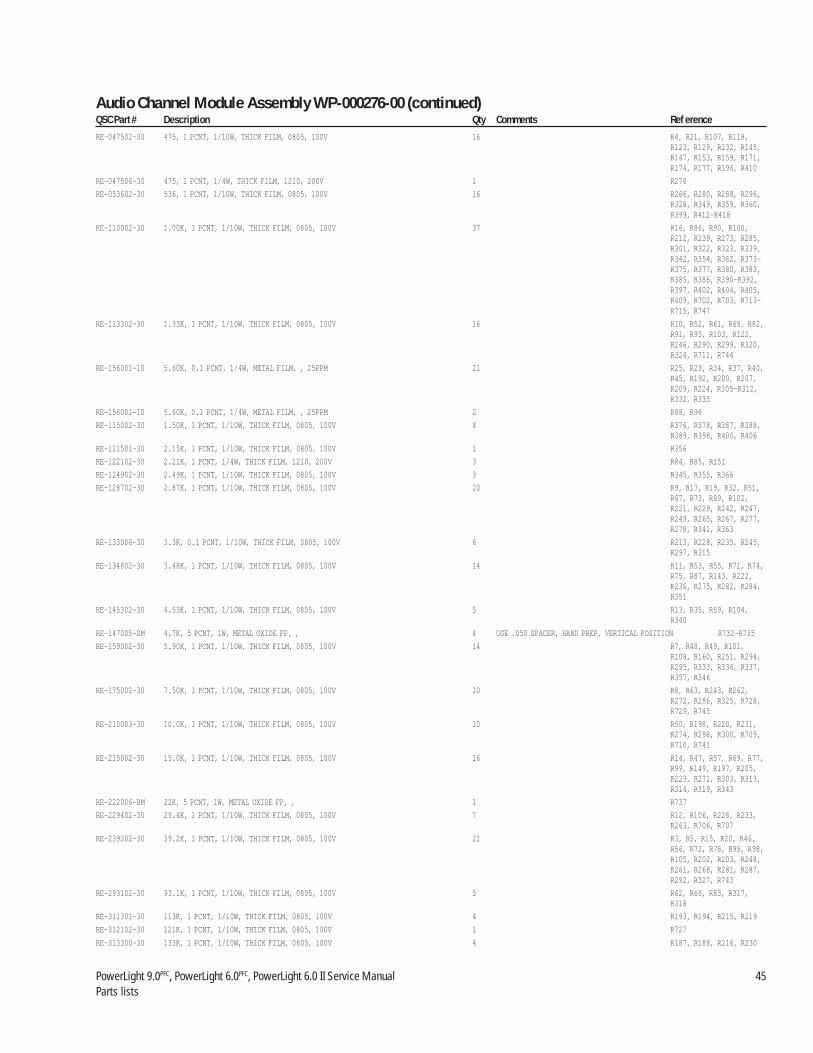
PowerLight 9.0PFC, PowerLight 6.0PFC, PowerLight 6.0 II Service Manual 45Parts lists
RE-047502-30 475, 1 PCNT, 1/10W, THICK FILM, 0805, 100V 16 R4, R21, R107, R118,R123, R129, R132, R145,R147, R153, R159, R171,R174, R177, R196, R410
RE-047506-30 475, 1 PCNT, 1/4W, THICK FILM, 1210, 200V 1 R276
RE-053602-30 536, 1 PCNT, 1/10W, THICK FILM, 0805, 100V 16 R266, R280, R288, R296,R328, R349, R359, R360,R399, R412–R418
RE-110002-30 1.00K, 1 PCNT, 1/10W, THICK FILM, 0805, 100V 37 R16, R86, R90, R100,R212, R239, R273, R285,R301, R322, R323, R339,R342, R354, R362, R373–R375, R377, R380, R383,R385, R386, R390–R392,R397, R402, R404, R405,R409, R702, R703, R713–R715, R747
RE-113302-30 1.33K, 1 PCNT, 1/10W, THICK FILM, 0805, 100V 16 R10, R52, R61, R65, R82,R91, R93, R103, R122,R246, R290, R299, R320,R324, R711, R744
RE-156001-10 5.60K, 0.1 PCNT, 1/4W, METAL FILM, , 25PPM 21 R25, R29, R34, R37, R40,R45, R192, R200, R207,R209, R224, R305–R312,R332, R335
RE-156001-10 5.60K, 0.1 PCNT, 1/4W, METAL FILM, , 25PPM 2 R88, R96
RE-115002-30 1.50K, 1 PCNT, 1/10W, THICK FILM, 0805, 100V 8 R376, R378, R387, R388,R389, R398, R400, R406
RE-121501-30 2.15K, 1 PCNT, 1/10W, THICK FILM, 0805, 100V 1 R356
RE-122102-30 2.21K, 1 PCNT, 1/4W, THICK FILM, 1210, 200V 3 R84, R85, R151
RE-124902-30 2.49K, 1 PCNT, 1/10W, THICK FILM, 0805, 100V 3 R345, R355, R366
RE-128702-30 2.87K, 1 PCNT, 1/10W, THICK FILM, 0805, 100V 20 R9, R17, R19, R32, R51,R67, R73, R89, R102,R221, R229, R242, R247,R249, R265, R267, R277,R278, R341, R363
RE-133006-30 3.3K, 0.1 PCNT, 1/10W, THICK FILM, 0805, 100V 6 R213, R228, R235, R245,R297, R315
RE-134802-30 3.48K, 1 PCNT, 1/10W, THICK FILM, 0805, 100V 14 R11, R53, R55, R71, R74,R75, R87, R143, R222,R236, R275, R282, R284,R351
RE-145302-30 4.53K, 1 PCNT, 1/10W, THICK FILM, 0805, 100V 5 R13, R35, R59, R104,R340
RE-147005-DM 4.7K, 5 PCNT, 1W, METAL OXIDE FP, , 4 USE .050 SPACER, HAND PREP, VERTICAL POSITION R732–R735
RE-159002-30 5.90K, 1 PCNT, 1/10W, THICK FILM, 0805, 100V 14 R7, R48, R49, R101,R108, R160, R251, R294,R295, R333, R336, R337,R357, R346
RE-175002-30 7.50K, 1 PCNT, 1/10W, THICK FILM, 0805, 100V 10 R8, R63, R243, R262,R272, R286, R325, R728,R729, R745
RE-210003-30 10.0K, 1 PCNT, 1/10W, THICK FILM, 0805, 100V 10 R50, R198, R220, R231,R274, R298, R300, R709,R710, R741
RE-215002-30 15.0K, 1 PCNT, 1/10W, THICK FILM, 0805, 100V 16 R14, R47, R57, R69, R77,R99, R149, R197, R205,R223, R271, R303, R313,R314, R319, R343
RE-222006-BM 22K, 5 PCNT, 1W, METAL OXIDE FP, , 1 R737
RE-229402-30 29.4K, 1 PCNT, 1/10W, THICK FILM, 0805, 100V 7 R12, R106, R226, R233,R263, R706, R707
RE-239202-30 39.2K, 1 PCNT, 1/10W, THICK FILM, 0805, 100V 21 R3, R5, R15, R20, R46,R56, R72, R76, R95, R98,R105, R202, R203, R248,R261, R268, R281, R287,R292, R327, R743
RE-293102-30 93.1K, 1 PCNT, 1/10W, THICK FILM, 0805, 100V 5 R62, R66, R83, R317,R318
RE-311301-30 113K, 1 PCNT, 1/10W, THICK FILM, 0805, 100V 4 R193, R194, R215, R219
RE-312102-30 121K, 1 PCNT, 1/10W, THICK FILM, 0805, 100V 1 R727
RE-313300-30 133K, 1 PCNT, 1/10W, THICK FILM, 0805, 100V 4 R187, R188, R216, R230
Audio Channel Module Assembly WP-000276-00 (continued)QSC Part # Description Qty Comments Ref erence

46 QSC Audio Products, Inc.TD-000083-00
RE-321002-10 210K, 0.1 PCNT, 1/4W, METAL FILM, , 25PPM 23 R24, R28, R33, R36, R39,R44, R195, R204, R211,R225, R232, R234, R241,R253–R260, R331, R334
RE-330902-30 309K, 1 PCNT, 1/10W, THICK FILM, 0805, 100V 3 R60, R64, R81
RE-339005-BC 390K, 5 PCNT, 1/4W, CARBON FILM, , 1 R344
RE-339201-30 392K, 1 PCNT, 1/10W, THICK FILM, 0805, 100V 5 R190, R199, R208, R289,R304
SC-061041-PP PHILLIPS TYPE 2, PANHEAD, #6, 0.25" L, BLACK, TYPE AB 8
SC-080123-HC HEX, CAP, #8-32, 0.625" L, BLACK, 15
WC-000112-10 JUMPER, 0.2" TEFLON INSULATION, 22 AWG, 1 CONDUCTOR, , 0.3" L, AUTO INSERTABLE 8 W1– W8
WC-000129-00 RIBBON CABLE ASSY, , 28 AWG, 16 CONDUCTOR, PL9.0, 12" L, 1
XF-000038-00 TRANSFORMER, HOUSEKEEPING, , , , PL9.0, , AMP MODULE 1 T1
XF-000040-00 INDUCTOR, , TOROID, 0.5UH, PL9.0, , 2 L2, L3
XF-000049-00 INDUCTOR, COMMON MODE, , 120UH, , , 1 NO POLARITY L1
XF-000068-00 INDUCTOR, ZOBEL, , 1UH, , , 1 L4
Audio Channel Module Assembly (QSC part # WP-000182-00)Where used: PL 9.0PFC, 120 and 230 volts.This is a subassembly of the Chassis Assembly, WP-000170-00 or WP-000170-02; two per amplifier.QSC Part # Description Qty Comments ReferenceCA-027001-30 27PF, 5 PCNT, 50V, CERAMIC NPO, 0805, 3 C52, C128, C134
CA-027002-30 27PF, 5 PCNT, 250V, CERAMIC NPO, 1206, 3 C15, C35, C51
CA-033001-30 33PF, 5 PCNT, 100V, CERAMIC NPO, 0805, 8 C84, C139, C140, C143–C147
CA-110002-30 100PF, 5 PCNT, 50V, CERAMIC NPO, 0805, 6 C93, C99, C109, C112,C113, C116
CA-118000-30 180PF, 5 PCNT, 100V, CERAMIC NPO, 0805, 1 C50CA-122002-30 220PF, 5 PCNT, 50V, CERAMIC NPO, 0805, 2 C54, C124
CA-130000-30 300PF, 5 PCNT, 50V, CERAMIC NPO, 0805, 1 C130CA-133002-30 330PF, 5 PCNT, 50V, CERAMIC NPO, 0805, 5 C115, C132, C133, C730,
C732
CA-147004-30 470PF, 5 PCNT, 50V, CERAMIC NPO, 0805, 4 C32, C43, C46, C58
CA-168003-30 680PF, 5 PCNT, 50V, CERAMIC NPO, 0805, 1 C713
CA-310001-10 0.01UF, 10 PCNT, 100V, FILM, DIPPEDn, 1 C745
CA-310004-30 0.01UF, 10 PCNT, 50V, CERAMIC X7R, 1206, 3 C81, C709, C710
CA-322005-30 0.022UF, 5 PCNT, 250V, FILM, 2220, 5 C725–C727, C740, C741
CA-410006-30 0.1UF, 10 PCNT, 50V, CERAMIC X7R, 1206, 68 C3–C5, C10, C17, C18,C21, C22, C29, C36–C38,C40, C42, C47, C60, C82,C83, C90, C91, C94, C96,C97, C100, C104, C106,C110, C118–C120, C122,C123, C136, C137, C708,C711, C712, C720–C722,C728, C733–C737, C744
CA-410009-00 0.1UF, 5 PCNT, 250V, FILM, WRAPPED, 4 USE .050 SPACER THIS PART HAS TWO DIFFERENT PREP C64, C65,C66, C67
CA-410009-00 0.1UF, 5 PCNT, 250V, FILM, WRAPPED, 2 USE .050 SPACER (PREP BY HAND AT VERTICAL POSITION) THIS PART HASTWO DIFFERENT PREP C723, C724
CA-447006-30 0.47UF, 20 PCNT, 25V, TANTALUM, 3216, 6 C34, C39, C44, C92,C102, C103
CA-510004-30 1.0UF, 20 PCNT, 50V, CERAMIC Z5U, 1210, 5 C14, C714, C717–C719
CA-610005-30 10UF, 20 PCNT, 35V, TANTALUM, SMT, 10 C2, C8, C11–C13, C16,C27, C20, C101, C105
CA-610008-30 10UF, 20 PCNT, 20V, TANTALUM, 6032, 8 C70–C77
CA-622002-30 22UF, 20 PCNT, 25V, TANTALUM, SMT, 18 C6, C7, C19, C30, C31,C33, C48, C49, C55, C62,C63, C68, C107, C111,C117, C125, C126, C129
CA-633001-00 33UF, 20 PCNT, 400V, ELECTROLYTIC, , 1 USE .050 SPACER C1
Audio Channel Module Assembly WP-000276-00 (continued)QSC Part # Description Qty Comments Ref erence

PowerLight 9.0PFC, PowerLight 6.0PFC, PowerLight 6.0 II Service Manual 47Parts lists
CA-647003-10 47UF, 10 PCNT, 10V, ELECTROLYTIC, , NON-POLAR LOW PROFILE 10 C28, C88, C89, C98,C108, C114, C121, C127,C131, C742
CA-710001-10 100UF, 20 PCNT, 35V, ELECTROLYTIC, , 1 C59
CA-922002-00 22000UF, 20 PCNT, 50V, ELECTROLYTIC, , 4 C9, C26, C41, C57
CH-000074-00 HEAT SINK, AUDIO, 8", PL9.0, 3
CH-000075-00 HEAT SINK, AUDIO, 14", PL9.0, 1
CH-000091-00 CLAMP, TO-264, 5.1", PL9.0, 2
CH-000091-01 CLAMP, TO-264, 4.5", PL9.0, 3
CO-000033-CO HEADER, 0.1" CENTERS, 4 POS (1X4), MALE, RAMP LOCK 1 J5
CO-000056-CO HEADER, 0.1" CENTERS, 16 POS (2X8), MALE, LATCHING BOX 1 J7
CO-000074-00 HEADER, 0.1" CENTERS, 8 POS (1X8), MALE, RAMP LOCK 1 J4
CO-000124-00 BARRIER STRIP, 0.375" CENTERS, 5 POS, , SHORT PIN 1 J3
HW-080005-SO SPACER, 0.312" ROUND, #8, 0.187" L, BRASS, SWAGE 4
HW-080008-SO SPACER, 0.312" ROUND, #8, 0.187" L, ALUMINUM, SWAGE 11
IC-000046-30 OPAMP, DUAL, TLO72, SMT, 10 U2, U5, U6, U9, U15,U17, U19, U20, U22, U23
IC-000047-30 COMPARATOR, DUAL, LM393, SMT, 2 U7, U8
IC-000048-30 OPAMP, DUAL, MC33078, , 1 U18
IC-000059-00 TOP SWITCH, , TOP202, , 1 U3
IC-000067-30 DIFFERENTIAL AMPLIFIER, DUAL, CA3054, SMT, 5 U21, U24, U25, U26, U28
IC-000070-30 VOLTAGE REFERENCE, +2.5V, LM4040DIM3X-2.5, , 1 U1
IC-000071-00 SENSOR, TEMPERATURE, LM35DZ, , 1 U10
IC-000073-30 TRANSCONDUCTANCE OPAMP, DUAL, LM13600M, , 1 U16
MS-000102-00 SHIELD, ELECTRO-MAGNETIC, INSULATED, PL9.0, 1
NW-100300-00 PRESS-IN NUT, #10-32, , , 2
PC-000182-00 PCB MAIN, PL 9.0, , 1
PL-000091-00 INSULATOR, STEP SWITCH, PL9.0, THERMALLY CONDUCTIVE, , 1
PL-000092-00 ISOLATOR, SPRING, PL9.0, FR-4 PCB, , 1
PL-000094-00 INSULATOR, CAPACITOR, PL9.0, FISH PAPER, , 1
PL-000112-00 RIVET, , 0.156" X 0.322", PLASTIC, , 1
PL-000121-00 SPACER, LED/TO-92, 0.18", PVC, BLACK, 1
PL-905156-SP SPACER, ROUND, 0.047"ID X 0.25"OD X 0.155"L, NYLON, , 6PL-905385-SP SPACER, ROUND, 0.047"ID X 0.25"OD X 0.385"L, NYLON, , 1
PT-250000-AT TRIM, 5K, 20 PCNT, 0.15W, , 1 VR1
QD-000024-QD DIODE ZENER, 6.2V, , 0.25W, DZ901116G, DO-35, 3 D96–D98
QD-000062-10 TRANSISTOR NPN, 40V, 0.2A, 1.5W, 2N3904, TO-92, 1 Q700
QD-000063-10 TRANSISTOR PNP, 40V, 0.2A, 1.5W, 2N3906, TO-92, 1 Q701
QD-000065-10 TRANSISTOR PNP, 300V, 0.5A, 1.5W, MPSA92, TO-92, 3 Q23, Q83, Q88
QD-000078-10 TRANSISTOR NPN DARLINGTON, 30V, 0.5A, 1.5W, MPSA13, TO-92, 3 Q3, Q16, Q26
QD-000080-20 DIODE ZENER, 11V, , 1W, 1N4741A, DO-41, 7 D29, D33, D48, D50, D53–D55
QD-000102-30 DIODE, 75V, 0.075A, , IMBD4148, SOT-23, 4NS 49 D15, D18, D22, D23, D25,D27, D28, D32, D35, D38,D39, D51, D58, D59, D79,D84, D85, D87, D88, D90–D95, D706, D708, D713,D715, D717–D719, D720,D723–D736
QD-000103-30 TRANSISTOR NPN, 40V, 0.2A, 0.2W, MMST3904, SOT-23, 56 Q2, Q5, Q8, Q10, Q13,Q28, Q45, Q46, Q49, Q50,Q53, Q56, Q58, Q59, Q62,Q68, Q71, Q73–Q77, Q81,Q84, Q86, Q90, Q96,Q97, Q99, Q100, Q102,Q104, Q107, Q110, Q112,Q113, Q118, Q120, Q121,Q125–Q127, Q130, Q135–Q137, Q702, Q704
QD-000104-30 TRANSISTOR PNP, 40V, 0.2A, 0.2W, MMST3906, SOT-23, 65 Q7, Q11, Q20, Q31, Q34,Q54, Q55, Q57, Q60, Q64–Q67, Q69, Q70, Q78, Q79,Q82, Q85, Q91–Q95, Q98,Q101, Q103, Q105, Q106,Q108, Q109, Q111, Q114–Q117, Q119, Q122–Q124,Q128, Q129, Q131–Q133,Q703, Q705
Audio Channel Module Assembly WP-000182-00 (continued)QSC Part # Description Qty Comments Ref erence

48 QSC Audio Products, Inc.TD-000083-00
QD-000105-30 TRANSISTOR NPN, 300V, 0.2A, 0.2W, MMBTA42, SOT-23, 6 Q6, Q18, Q19, Q21, Q22,Q30
QD-000106-30 TRANSISTOR PNP, 300V, 0.2A, 0.2W, MMBTA92, SOT-23, 4 Q9, Q15, Q32, Q169
QD-000107-30 JFET N-CHANNEL, 35V, , , PMBFJ112, SOT-23, RDS ON 50 OHMS 2 Q29, Q706
QD-000108-30 DIODE, 200V, 0.2A, , BAS21, SOT-23, 50NS 5 D6, D21, D24, D41, D42
QD-000109-30 DIODE ZENER, 4.7V, , 0.3W, BZX84C4V7, SOT-23, 1 D14
QD-000110-30 DIODE ZENER, 6.2V, , 0.3W, BZX84C6V2, SOT-23, 6 D30, D31, D36, D43, D81,D83
QD-000111-30 DIODE ZENER, 12V, , 0.3W, BZX84C12, SOT-23, 7 D3, D19, D40, D44, D46,D721, D722
QD-000114-30 DIODE ZENER, 150V, , 600W PEAK, P6SMB150AT3, SMB, 1 D11
QD-000115-30 DIODE RECTIFIER ULTRAFAST, 600V, 1A, , MURS160T3, SMB, 75NS 1 D12
QD-000116-30 DIODE RECTIFIER ULTRAFAST, 200V, 1A, , MURS120, SMB, 35NS 5 D2, D4, D7, D9, D13
QD-000123-10 TRANSISTOR NPN, 300V, 0.5A, 0.68W, MPSA42, TO-92, 5 Q25, Q47, Q48, Q51, Q52
QD-000124-10 TRANSISTOR PNP DARLINGTON, 30V, 0.5A, 0.625, MPSA63, TO-92, 3 Q4, Q17, Q27
QD-000127-30 TRANSISTOR PNP, 20V, 0.05A, 0.35W, MMBTH81, SOT-23, 2 Q72, Q80
QD-000128-30 TRANSISTOR NPN, 25V, 4A, 0.5W, MMBTH10, SOT-23, 2 Q87, Q89
QD-000129-00 TRANSISTOR PNP, 100V, 5A, 28W, MJF127, TO-220, 1 Q33
QD-000131-00 MOSFET N-CHANNEL, 70V, 110A, 500W, IXFK110N07, TO-264, 3 Q1, Q14, Q24
QD-000132-00 MOSFET N-CHANNEL, 200V, 74A, 416W, IXTK74N20, TO-264, 8 Q35–Q42
QD-000157-10 DIODE, 1000V, 1.5A, , 1N5399, DO-15, 1 D1
QD-000159-20 DIODE ZENER, 47V, , 1W, 1N4756, DO-41, 3 D5, D17, D37
QD-000160-00 DIODE RECTIFIER ULTRAFAST, 200V, 60A, , APT60D20B, TO-247AD, 85NS 3 D10, D34, D47
QD-000163-30 LED RED, , , , , SML-010, VOLTAGE REFERENCE 10 LD1–LD10
QD-004148-DX DIODE, 75V, 0.075A, , 1N4148, DO-35, 4NS 1 D714
RE-.04001-00 0.04, 1 PCNT, 20W, MICRONOX FILM, TO-220, 8 FLAT R137–R140, R163–R166
RE-.15001-00 1.5, 2 PCNT, 3W, METAL OXIDE FP, , 2 THIS PART HAS TWO DIFFERENT PREP (PREP BY HAND AT VERTICALPOSITION) (PREP BY XURON TOOL, IF COMPONENT IS BIG) USE .050SPACER. R700, R701
RE-.15001-00 1.5, 2 PCNT, 3W, METAL OXIDE FP, , 2 THIS PART HAS TWO DIFFERENT PREP (PREP BY HAND AT VERTICALPOSITION) (PREP BY XURON TOOL, IF COMPONENT IS BIG) USE .050SPACER. R68, R97
RE-.15002-30 1.5, 5 PCNT, 1W, THICK FILM, 2512, 200V 3 R722, R723, R724
RE-.22100-30 2.21, 1 PCNT, 1/10W, THICK FILM, 0805, 100V 8 R41, R126, R128, R131,R134, R154,R182, R466
RE-.24001-00 2.4, 5 PCNT, 5W, METAL OXIDE FP, , NON-INDUCTIVE 8 USE .050 SPACER FLUSH TO PCB R117, R119–R121, R719,R720
USE .300 SPACER R42, R79
RE-.68100-30 6.81, 1 PCNT, 1/10W, THICK FILM, 0805, 8 R23, R109, R110, R112,R158, R161, R172, R183
RE-000009-PT PTC, 100 OHMS, 470 OHMS, , 90C, MURATA-ERIE 1 USE THE UNPREPPED PARTS FROM PREP AREA, R1HAND CUT ACCORDING TO THE DRAWING
RE-001501-10 15, 1 PCNT, 1/8W, METAL FILM, , 7 R2, R43, R94, R115,R116, R708, R736
RE-003921-30 39.2, 1 PCNT, 1/8W, THICK FILM, 1206, 200V 1 R142
RE-004701-10 47, 5 PCNT, 2W, METAL OXIDE FP, MINI, 2 R26, R27
RE-004752-30 47.5, 1 PCNT, 1/10W, THICK FILM, 0805, 100V 7 R201, R237, R361, R716–R718, R731
RE-006803-10 68, 5 PCNT, 1/2W, CARBON FILM, , 4 R113, R114, R146, R156
RE-010002-30 100, 1 PCNT, 1/10W, THICK FILM, 0805, 100V 49 R6, R18, R54, R58, R70,R78, R80, R210, R214,R217, R218, R227, R238,R264, R269, R270, R279,R291, R293, R316, R321,R329, R330, R338, R350,R353, R364, R367, R369–R372, R379, R381, R382,R384, R393, R394–R396,R401, R403, R407, R408
RE-010003-10 100, 1 PCNT, 1/8W, METAL FILM, , 2 R185, R186
RE-015002-10 150, 5 PCNT, 1/2W, CARBON FILM, , 2 R111, R411
RE-015002-10 150, 5 PCNT, 1/2W, CARBON FILM, , 2 THIS PART HAS TWO DIFFERENT PREP R725, R726
RE-015006-30 150, 1 PCNT, 1/8W, THICK FILM, 1206, 200V 1 R144
RE-020002-30 200, 1 PCNT, 1/10W, THICK FILM, 0805, 100V 14 R30, R150, R189, R191,R240, R244, R250, R252,R302, R326, R348, R352,R742, R746
Audio Channel Module Assembly WP-000182-00 (continued)QSC Part # Description Qty Comments Ref erence
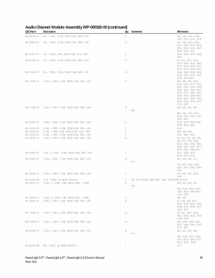
PowerLight 9.0PFC, PowerLight 6.0PFC, PowerLight 6.0 II Service Manual 49Parts lists
RE-022100-30 221, 1 PCNT, 1/10W, THICK FILM, 0805, 100V 8 R22, R92, R136, R148,R152, R173, R176, R178
RE-030900-30 309, 1 PCNT, 1/10W, THICK FILM, 0805, 100V 16 R31, R38, R124, R125,R127, R130, R133, R135,R141, R155, R162, R167–R169, R180, R181
RE-033203-30 332, 1 PCNT, 1/4W, THICK FILM, 1210, 200V 5 R206, R276, R347, R358,R365
RE-047502-30 475, 1 PCNT, 1/10W, THICK FILM, 0805, 100V 16 R4, R21, R107, R118,R123, R129, R132, R145,R147, R153, R159, R171,R174, R177, R196, R410
RE-053602-30 536, 1 PCNT, 1/10W, THICK FILM, 0805, 100V 16 R266, R280, R288, R296,R328, R349, R359, R360,R399, R412–R418
RE-110002-30 1.00K, 1 PCNT, 1/10W, THICK FILM, 0805, 100V 37 R16, R86, R90, R100,R212, R239, R273, R285,R301, R322, R323, R339,R342, R354, R362, R373–R375, R377, R380, R383,R385, R386, R390–R392,R397, R402, R404, R405,R409, R702, R703, R713–R715, R747
RE-113302-30 1.33K, 1 PCNT, 1/10W, THICK FILM, 0805, 100V 15 R10, R52, R61, R65,R82,
R91, R93, R103, R122,R246, R290, R299, R320,R324, R744
RE-115002-30 1.50K, 1 PCNT, 1/10W, THICK FILM, 0805, 100V 8 R376, R378, R387–R389,R398, R400, R406
RE-121501-30 2.15K, 1 PCNT, 1/10W, THICK FILM, 0805, 100V 1 R356
RE-122102-30 2.21K, 1 PCNT, 1/4W, THICK FILM, 1210, 200V 3 R84, R85, R151
RE-124902-30 2.49K, 1 PCNT, 1/10W, THICK FILM, 0805, 100V 3 R345, R355, R366
RE-128702-30 2.87K, 1 PCNT, 1/10W, THICK FILM, 0805, 100V 21 R9, R17, R19, R32, R51,R67, R73, R89, R102,R221, R229, R242, R247,R249, R265, R267, R277,R278, R341, R363,R711
RE-133006-30 3.3K, 0.1 PCNT, 1/10W, THICK FILM, 0805, 100V 6 R213, R228, R235,R245, R297, R315
RE-134802-30 3.48K, 1 PCNT, 1/10W, THICK FILM, 0805, 100V 14 R11, R53, R55, R71,R74,
R75, R87, R143, R222,R236, R275, R282, R284,R351
RE-145302-30 4.53K, 1 PCNT, 1/10W, THICK FILM, 0805, 100V 5 R13, R35, R59, R104,R340
RE-147005-DM 4.7K, 5 PCNT, 1W, METAL OXIDE FP, , 4 USE .050 SPACER, HAND PREP, VERT. POSITION R732–R735
RE-156001-10 5.60K, 0.1 PCNT, 1/4W, METAL FILM, , 25PPM 21 R25, R29, R34, R37,R40,
R45, R192, R200, R207,R209, R224, R305–R312,R332, R335
RE-156001-10 5.60K, 0.1 PCNT, 1/4W, METAL FILM, , 25PPM 2 R88, R96
RE-159002-30 5.90K, 1 PCNT, 1/10W, THICK FILM, 0805, 100V 14 R7, R48, R49, R101,R108, R160, R251, R294,R295, R333, R336, R337,R346, R357
RE-175002-30 7.50K, 1 PCNT, 1/10W, THICK FILM, 0805, 100V 10 R8, R63, R243, R262,R272, R286, R325, R728,R729, R745
RE-210003-30 10.0K, 1 PCNT, 1/10W, THICK FILM, 0805, 100V 10 R50, R198, R220, R231,R274, R298, R300, R709,R710, R741
RE-215002-30 15.0K, 1 PCNT, 1/10W, THICK FILM, 0805, 100V 16 R14, R47, R57, R69,R77,
R99, R149, R197, R205,R223, R271, R303, R313,R314, R319, R343
RE-222006-BM 22K, 5 PCNT, 1W, METAL OXIDE FP, , 1 R737
Audio Channel Module Assembly WP-000182-00 (continued)QSC Part # Description Qty Comments Ref erence
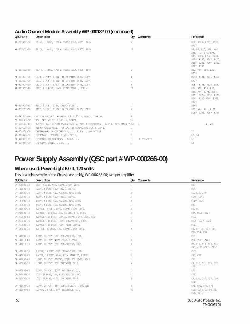
50 QSC Audio Products, Inc.TD-000083-00
RE-229402-30 29.4K, 1 PCNT, 1/10W, THICK FILM, 0805, 100V 5 R12, R106, R263, R706,R707
RE-239202-30 39.2K, 1 PCNT, 1/10W, THICK FILM, 0805, 100V 23 R3, R5, R15, R20, R46,R56, R72, R76, R95,R98, R105, R202, R203,R226, R233, R248, R261,R268, R281, R287, R292,R327, R743
RE-293102-30 93.1K, 1 PCNT, 1/10W, THICK FILM, 0805, 100V 5 R62, R66, R83, R317,R318
RE-311301-30 113K, 1 PCNT, 1/10W, THICK FILM, 0805, 100V 4 R193, R194, R215, R219
RE-312102-30 121K, 1 PCNT, 1/10W, THICK FILM, 0805, 100V 1 R727
RE-313300-30 133K, 1 PCNT, 1/10W, THICK FILM, 0805, 100V 4 R187, R188, R216, R230
RE-321002-10 210K, 0.1 PCNT, 1/4W, METAL FILM, , 25PPM 23 R24, R28, R33, R36,R39, R44, R195, R204,R211, R225, R232, R234,R241, R253–R260, R331,R334
RE-339005-BC 390K, 5 PCNT, 1/4W, CARBON FILM, , 1 R344
RE-339201-30 392K, 1 PCNT, 1/10W, THICK FILM, 0805, 100V 8 R60, R64, R81, R190,R199, R208, R289, R304
SC-061041-PP PHILLIPS TYPE 2, PANHEAD, #6, 0.25" L, BLACK, TYPE AB 8
SC-080123-HC HEX, CAP, #8-32, 0.625" L, BLACK, 15
WC-000112-10 JUMPER, 0.2" TEFLON INSULATION, 22 AWG, 1 CONDUCTOR, , 0.3" L, AUTO INSERTABLE 8 W1–W8
WC-000129-00 RIBBON CABLE ASSY, , 28 AWG, 16 CONDUCTOR, PL9.0, 12" L, 1
XF-000038-00 TRANSFORMER, HOUSEKEEPING, , , , PL9.0, , AMP MODULE 1 T1
XF-000040-00 INDUCTOR, , TOROID, 0.5UH, PL9.0, , 2 L2, L3
XF-000049-00 INDUCTOR, COMMON MODE, , 120UH, , , 1 NO POLARITY L1
XF-000068-00 INDUCTOR, ZOBEL, , 1UH, , , 1 L4
Power Supply Assembly (QSC part # WP-000266-00)Where used: PowerLight 6.0 II, 120 voltsThis is a subassembly of the Chassis Assembly, WP-000268-00; two per amplifier.QSC Part # Description Qty Comments ReferenceCA-068002-30 68PF, 5 PCNT, 50V, CERAMIC NPO, 0805, 1 C40
CA-110001-10 100PF, 5 PCNT, 500V, MICA, DIPPED, 1 C147
CA-110002-30 100PF, 5 PCNT, 50V, CERAMIC NPO, 0805, 3 C1, C30, C39
CA-133001-10 330PF, 5 PCNT, 500V, MICA, DIPPED, 2 C145, C146
CA-147003-30 470PF, 5 PCNT, 50V, CERAMIC NPO, 1206, 2 C119, C121
CA-147004-30 470PF, 5 PCNT, 50V, CERAMIC NPO, 0805, 1 C22
CA-210006-30 0.001UF, 2 PCNT, 100V, CERAMIC NPO, 0805, 2 C2, C5
CA-215003-30 0.0015UF, 10 PCNT, 25V, CERAMIC X7R, 0805, 3 C44, C120, C124
CA-222001-00 0.0022UF, 20 PCNT, 125VAC, CERAMIC Y5U, DISC, YCAP 1 C122
CA-227001-30 0.0027UF, 10 PCNT, 100V, CERAMIC X7R, 0805, 3 C108, C109, C128
CA-233001-10 0.0033UF, 10 PCNT, 100V, FILM, DIPPED, 1 C113
CA-347002-30 0.047UF, 20 PCNT, 50V, CERAMIC Z5U, 0805, 9 C3, C4, C11–C13, C15,C28, C64, C81
CA-410006-30 0.1UF, 10 PCNT, 50V, CERAMIC X7R, 1206, 1 C18
CA-410011-00 0.1UF, 10 PCNT, 400V, FILM, DIPPED, 3 C14, C107, C123
CA-410012-30 0.1UF, 10 PCNT, 25V, CERAMIC X7R, 0805, 9 C7, C17, C19, C20, C61,C65, C125, C135, C162
CA-422004-30 0.22UF, 10 PCNT, 50V, CERAMIC X7R, 1206, 1 C155
CA-447003-00 0.47UF, 10 PCNT, 400V, FILM, WRAPPED, PULSE 2 C37, C38
CA-510006-00 1.0UF, 20 PCNT, 250VAC, FILM, BOX STYLE, XCAP 1 C23
CA-515002-30 1.5UF, 20 PCNT, 35V, TANTALUM, 3216, 6 C6, C10, C21, C75, C77,C79
CA-522003-00 2.2UF, 20 PCNT, 400V, ELECTROLYTIC, , 1 C73
CA-610006-30 10UF, 20 PCNT, 16V, ELECTROLYTIC, SMT, 1 C78
CA-610007-30 10UF, 20 PCNT, 6.3V, TANTALUM, 3528, 6 C9, C31, C32, C52, C80,C114
CA-710004-10 100UF, 20 PCNT, 25V, ELECTROLYTIC, , LOW ESR 4 C71, C72, C74, C76
CA-810004-00 1000UF, 20 PCNT, 55V, ELECTROLYTIC, , 20 C151–C154, C158–C161,C164–C175
Audio Channel Module Assembly WP-000182-00 (continued)QSC Part # Description Qty Comments Ref erence

PowerLight 9.0PFC, PowerLight 6.0PFC, PowerLight 6.0 II Service Manual 51Parts lists
CA-822200-AE 2200UF, 20 PCNT, 200V, ELECTROLYTIC, , 6 C132, C133, C136, C137,C140, C141
CH-000103-00 CLAMP, TO-3PL, 22 GA, PLX3002, 3
CH-000262-00 HEAT SINK, PFC, 11", EVICTOR, 1
CH-000263-00 HEAT SINK, MAIN SUPPLY, 13.5", EVICTOR, 1
CO-000074-00 HEADER, 0.1" CENTERS, 8 POS (1X8), MALE, RAMP LOCK 1 J1
HW-000036-00 STANDOFF, 0.344" ROUND, #8, 0.187" L, ALUMINUM, SWAGE 4
HW-080080-PS STUD, PEM STYLE, #8-32, 0.500" L, TIN PLATED BRONZE, 2 E2, E1
IC-000024-00 CONTROLLER, PWM, SG3525AN, , 1 U19
IC-000031-00 OPTO ISOLATOR, , 4N30, , 1 U15
IC-000051-00 OPTO ISOLATOR, , MOC8101, , 1 U1
IC-000053-30 TIMER, DUAL, LM556, , 1 U14
IC-000054-30 COMPARATOR, QUAD, LM339AM, SMT, 1 U13
IC-000133-30 COMPARATOR, SINGLE, LM311, SMT, 2 U2, U3
IC-000134-00 DRIVER, MOSFET, IR2110, , 1 U18
IC-000235-00 TOP SWITCH, , TOP224, , 1 ASSY /W MS-000048-HS U29
MS-000048-HS HEAT SINK, TO-220, 1.375" X 0.86" X 0.395", LONG TAB, PLUG-IN 1 REF: U29
MS-000143-30 FUSE, 0.5A, 32V, 1206, FAST (MS-000115-30) 1 F1
PC-000266-00 POWER SUPPLY, EVICTOR, , 1
PL-000010-00 BUMPER, ADHESIVE BACKED, 0.5" X 0.5", POLYURETHANE, BLACK, 8
PL-000114-00 INSULATOR, IGBT/RECTIFIER, 1.25" X 3.20", THERMALLY CONDUCTIVE, , 2
PL-000121-00 SPACER, LED/TO-92, 0.18", PVC, BLACK, 1 REF: R28
PL-000126-00 SPRING SEAT, TRANSISTOR, PLX, NYLON, , 3
PL-000134-00 GROMMET, VIBRATION DAMPING, 0.375" OD, NEOPRENE, , 1
QD-000022-QD DIODE ZENER, 18V, , 1W, 1N4746A, DO-41, 1 D95
QD-000023-QD DIODE ZENER, 180V, , 1.5W, 1N5955A, DO-41, 8 D9–D14, D19, D20
QD-000042-00 DIODE RECTIFIER ULTRAFAST, 400V, 3A, , MUR440, DO-201AD, 50NS 2 D70, D71
QD-000047-00 DIODE ZENER, 200V, , 1.5W, 1N5956B, DO-41, 1 D2
QD-000074-00 DIODE RECTIFIER ULTRAFAST, 400V, 15A, , MUR1540, TO-220, 50NS 2 D75, D80
QD-000102-30 DIODE, 75V, 0.075A, , IMBD4148, SOT-23, 4NS 4 D4, D29, D72, D89
QD-000103-30 TRANSISTOR NPN, 40V, 0.2A, 0.2W, MMST3904, SOT-23, 11 Q3, Q92, Q93, Q102,Q103, Q105, Q107–Q110,Q114
QD-000104-30 TRANSISTOR PNP, 40V, 0.2A, 0.2W, MMST3906, SOT-23, 7 Q94, Q95, Q100, Q101,Q104, Q111, Q112
QD-000108-30 DIODE, 200V, 0.2A, , BAS21, SOT-23, 50NS 1 D87
QD-000110-30 DIODE ZENER, 6.2V, , 0.3W, BZX84C6V2, SOT-23, 3 D21, D24, D28
QD-000113-30 DIODE ZENER, 10V, , 0.3W, BZX84C10, SOT-23, 2 D1, D5
QD-000115-30 DIODE RECTIFIER ULTRAFAST, 600V, 1A, , MURS160T3, SMB, 75NS 3 D58, D86, D100
QD-000116-30 DIODE RECTIFIER ULTRAFAST, 200V, 1A, , MURS120, SMB, 35NS 3 D25, D93, D96
QD-000125-00 DIODE RECTIFIER FAST, 600V, 37A, , DSEI30-06A, TO-247AD, 50NS 2 D77, D84
QD-000137-30 DIODE SCHOTTKY, 15V, 0.01A, , MMBD301LT1, SOT-23, VF MAX 0.6V 1 D3
QD-000163-30 LED RED, , , , , SML-010, VOLTAGE REFERENCE 1 LD1
QD-000170-00 BRIDGE RECTIFIER, 600V, 50A, , , , IN-LINE 1 (USE .050 SPACER FOR OLEMEF, FACE DOWN) BR1
QD-000229-10 DIODE, 250V, 0.25A, , BAV21, DO-35, 50NS 2 D22, D23
QD-000235-00 RECTIFIER DUAL COMMON CATHODE, 500V, 30A, , BYV74W-500, TO-247, 2 D73, D85
QD-000243-00 IGBT, 600V, 32A, 140W, IXGR32N60C, TO-247, 2 Q96, Q97
QD-000248-30 DIODE ZENER, 15V, , 350MW, BZX84C15TR, SOT-23, 2 D6, D27
RE-.49900-30 4.99, 1 PCNT, 1/8W, THICK FILM, 1206, 200V 2 R359, R360
RE-000002-30 0, , , THICK FILM, 0805, JUMPER 1 R61
RE-000210-NR NTC, 10 OHMS, 15 AMPS, , , INRUSH LIMIT 1 R324
RE-000230-NR NTC, 10K, , 15 PCNT, , -4.4 PCNT PER C 1 R28
RE-001003-30 10, 1 PCNT, 1/8W, THICK FILM, 1206, 200V 1 R358
RE-001505-CC 15, 5 PCNT, 1/2W, CARBON FILM, , 1 R174
RE-001502-10 15, 5 PCNT, 2W, METAL OXIDE FP, MINI, 1 R350
RE-002100-30 21, 1 PCNT, 1/10W, THICK FILM, 0805, 100V 1 R62
RE-002203-10 22, 5 PCNT, 3W, METAL OXIDE FP, , 1 (USE .050 SPACER) R372
RE-004701-10 47, 5 PCNT, 2W, METAL OXIDE FP, MINI, 1 R35
RE-004752-30 47.5, 1 PCNT, 1/10W, THICK FILM, 0805, 100V 1 R33
RE-010002-30 100, 1 PCNT, 1/10W, THICK FILM, 0805, 100V 3 R2, R51, R57
RE-010700-30 107, 0.1 PCNT, 1/10W, THICK FILM, 0805, 100V 1 R21
RE-033203-30 332, 1 PCNT, 1/4W, THICK FILM, 1210, 200V 1 R180
RE-033205-30 332, 0.1 PCNT, 1/10W, THICK FILM, 0805, 100V 1 R16
RE-061901-30 619, 1 PCNT, 1/10W, THICK FILM, 0805, 100V 1 R96
Power Supply Assembly WP-000266-00 (continued)QSC Part # Description Qty Comments Ref erence

52 QSC Audio Products, Inc.TD-000083-00
RE-068001-10 680, 5 PCNT, 2W, METAL OXIDE FP, MINI, 1 R175
RE-090901-30 909, 1 PCNT, 1/10W, THICK FILM, 0805, 100V 1 R26
RE-093101-30 931, 1 PCNT, 1/10W, THICK FILM, 0805, 100V 1 R380
RE-113302-30 1.33K, 1 PCNT, 1/10W, THICK FILM, 0805, 100V 1 R22
RE-120002-30 2.00K, 1 PCNT, 1/10W, THICK FILM, 0805, 100V 1 R6
RE-122103-30 2.21K, 1 PCNT, 1/10W, THICK FILM, 0805, 100V 3 R18, R357, R367
RE-126700-30 2.67K, 1 PCNT, 1/10W, THICK FILM, 0805, 100V 1 R337
RE-128702-30 2.87K, 1 PCNT, 1/10W, THICK FILM, 0805, 100V 2 R1, R3
RE-147502-30 4.75K, 1 PCNT, 1/10W, THICK FILM, 0805, 100V 3 R12, R330, R339
RE-156202-30 5.62K, 0.1 PCNT, 1/10W, THICK FILM, 0805, 100V 3 R8, R13, R14
RE-163401-10 6.34K, 1 PCNT, 1/8W, METAL FILM, , 1 R4
RE-178702-30 7.87K, 0.1 PCNT, 1/10W, THICK FILM, 0805, 100V 1 R20
RE-197602-30 9.76K, 1 PCNT, 1/10W, THICK FILM, 0805, 100V 1 R338
RE-210003-30 10.0K, 1 PCNT, 1/10W, THICK FILM, 0805, 100V 12 R5, R9–R11, R17, R19,R24, R25, R63, R64,R336, R363
RE-212104-30 12.1K, 0.1 PCNT, 1/10W, THICK FILM, 0805, 100V 1 R15
RE-212702-30 12.7K, 1 PCNT, 1/10W, THICK FILM, 0805, 100V 1 R329
RE-215002-30 15.0K, 1 PCNT, 1/10W, THICK FILM, 0805, 100V 2 R48, R366
RE-229402-30 29.4K, 1 PCNT, 1/10W, THICK FILM, 0805, 100V 2 R29, R331
RE-230002-10 30K, 5 PCNT, 2W, METAL OXIDE FP, MINI, 1 R351
RE-230002-10 30K, 5 PCNT, 2W, METAL OXIDE FP, MINI, 5 R352–R356
RE-231601-30 31.6K, 1 PCNT, 1/10W, THICK FILM, 0805, 100V 1 R325
RE-239202-30 39.2K, 1 PCNT, 1/10W, THICK FILM, 0805, 100V 1 R332
RE-247503-30 47.5K, 1 PCNT, 1/10W, THICK FILM, 0805, 100V 1 R323
RE-249900-30 49.9K, 1 PCNT, 1/10W, THICK FILM, 0805, 100V 5 R7, R34, R49, R50, R66
RE-263401-30 63.4K, 1 PCNT, 1/10W, THICK FILM, 0805, 100V 2 R52, R53
RE-310002-30 100K, 1 PCNT, 1/10W, THICK FILM, 0805, 100V 2 R56, R55
RE-315002-30 150K, 1 PCNT, 1/8W, THICK FILM, 1206, 200V 2 R341, R342
RE-339202-30 392K, 1 PCNT, 1/8W, THICK FILM, 1206, 200V 1 R340
RE-348702-30 487K, 1 PCNT, 1/8W, THICK FILM, 1206, 200V 4 R321, R322, R326, R328
SC-063100-PP PHILLIPS, PANHEAD, #6, 0.625" L, ZINC, TYPE AB 10
SW-000058-00 RELAY, SPDT, 12VDC COIL, 15A, 240VAC, 1 K1
WC-0.4016-JW JUMPER, 0.3" TEFLON INSULATION, 16 AWG, 1 CONDUCTOR, , 0.4", 2 W9, W10
WC-000125-00 CABLE ASSY, DC OUTPUT, 10 AWG, 5 CONDUCTOR, PL9.0, 6" L, 1 REF: E4-E8(0-E8,1-E7,2-E6,3-E5,4-E4) FOLK TERMINAL FACE-UP
WC-000237-00 RIBBON CABLE, FLEX STRIP, 24 AWG, 12 CONDUCTOR, PL6.0II, 11.25" L, 1 USE SPACER BETWEEN XF-000208-00 AND CABLE
WC-5.2514-00 JUMPER, PVC INSULATION, 14 AWG, 1 CONDUCTOR, EVICTOR, 5.25" L, 1
XF-000005-00 BEAD, 100MHZ, 271 OHM, 7 L7–L13
XF-000194-00 TRANSFORMER, SWITCHING, , , , NEW PL6.0, , 1 T3
XF-000204-00 HOUSEKEEPING, FLYBACK, , , , EVICTOR, , 1 T2
XF-000206-00 INDUCTOR, COMMON MODE, TOROID, 81UH, EVICTOR, , 1 L4
XF-000208-00 INDUCTOR, SERIES RESONANT, TOROID, 1.0UH, , , 1 L6
Power Supply Assembly (QSC part # WP-000266-02)Where used: PowerLight 6.0 II, 230 volts.This is a subassembly of the Chassis Assembly, WP-000268-02; two per amplifier.QSC Part # Description Qty Comments ReferenceCA-068002-30 68PF, 5 PCNT, 50V, CERAMIC NPO, 0805, 1 C40
CA-110001-10 100PF, 5 PCNT, 500V, MICA, DIPPED, 1 C147
CA-110002-30 100PF, 5 PCNT, 50V, CERAMIC NPO, 0805, 3 C1, C30, C39
CA-133001-10 330PF, 5 PCNT, 500V, MICA, DIPPED, 2 C145, C146
CA-147003-30 470PF, 5 PCNT, 50V, CERAMIC NPO, 1206, 2 C119, C121
CA-147004-30 470PF, 5 PCNT, 50V, CERAMIC NPO, 0805, 1 C22
CA-210006-30 0.001UF, 2 PCNT, 100V, CERAMIC NPO, 0805, 2 C2, C5
CA-215003-30 0.0015UF, 10 PCNT, 25V, CERAMIC X7R, 0805, 3 C44, C120, C124
CA-222001-00 0.0022UF, 20 PCNT, 125VAC, CERAMIC Y5U, DISC, YCAP 1 C122
CA-227001-30 0.0027UF, 10 PCNT, 100V, CERAMIC X7R, 0805, 3 C108, C109, C128
CA-233001-10 0.0033UF, 10 PCNT, 100V, FILM, DIPPED, 1 C113
Power Supply Assembly WP-000266-00 (continued)QSC Part # Description Qty Comments Ref erence

PowerLight 9.0PFC, PowerLight 6.0PFC, PowerLight 6.0 II Service Manual 53Parts lists
CA-347002-30 0.047UF, 20 PCNT, 50V, CERAMIC Z5U, 0805, 9 C3, C4, C11–C13, C15,C28, C64, C81
CA-410011-00 0.1UF, 10 PCNT, 400V, FILM, DIPPED, 3 C14, C107, C123
CA-410012-30 0.1UF, 10 PCNT, 25V, CERAMIC X7R, 0805, 9 C7, C17, C19, C20, C61,C65, C125, C135, C162
CA-410006-30 0.1UF, 10 PCNT, 50V, CERAMIC X7R, 1206, 1 C18
CA-422004-30 0.22UF, 10 PCNT, 50V, CERAMIC X7R, 1206, 1 C155
CA-447003-00 0.47UF, 10 PCNT, 400V, FILM, WRAPPED, PULSE 2 C37, C38
CA-510006-00 1.0UF, 20 PCNT, 250VAC, FILM, BOX STYLE, XCAP 1 C23
CA-515002-30 1.5UF, 20 PCNT, 35V, TANTALUM, 3216, 6 C6, C10, C21, C75, C77,C79
CA-522003-00 2.2UF, 20 PCNT, 400V, ELECTROLYTIC, , 1 C73
CA-610006-30 10UF, 20 PCNT, 16V, ELECTROLYTIC, SMT, 1 C78
CA-610007-30 10UF, 20 PCNT, 6.3V, TANTALUM, 3528, 6 C9, C31, C32, C52, C80,C114
CA-710004-10 100UF, 20 PCNT, 25V, ELECTROLYTIC, , LOW ESR 4 C71, C72, C74, C76
CA-810004-00 1000UF, 20 PCNT, 55V, ELECTROLYTIC, , 20 C151–C154, C158–C161,C164–C175
CA-822200-AE 2200UF, 20 PCNT, 200V, ELECTROLYTIC, , 6 C132, C133, C136, C137,C140, C141
CH-000103-00 CLAMP, TO-3PL, 22 GA, PLX3002, 3
CH-000262-00 HEAT SINK, PFC, 11", EVICTOR, 1
CH-000263-00 HEAT SINK, MAIN SUPPLY, 13.5", EVICTOR, 1
HW-000036-00 STANDOFF, 0.344" ROUND, #8, 0.187" L, ALUMINUM, SWAGE 4
HW-080080-PS STUD, PEM STYLE, #8-32, 0.500" L, TIN PLATED BRONZE, 2 E1, E2
IC-000024-00 CONTROLLER, PWM, SG3525AN, , 1 U19
IC-000031-00 OPTO ISOLATOR, , 4N30, , 1 U15
IC-000051-00 OPTO ISOLATOR, , MOC8101, , 1 U1
IC-000053-30 TIMER, DUAL, LM556, , 1 U14
IC-000054-30 COMPARATOR, QUAD, LM339AM, SMT, 1 U13
IC-000133-30 COMPARATOR, SINGLE, LM311, SMT, 2 U2, U3
IC-000134-00 DRIVER, MOSFET, IR2110, , 1 U18
IC-000235-00 TOP SWITCH, , TOP224, , 1 ASSY /W MS-000048-HS U29
MS-000048-HS HEAT SINK, TO-220, 1.375" X 0.86" X 0.395", LONG TAB, PLUG-IN 1 REF: U29
MS-000143-30 FUSE, 0.5A, 32V, 1206, FAST (MS-000115-30) 1 F1
PC-000266-00 POWER SUPPLY, EVICTOR, , 1
PL-000010-00 BUMPER, ADHESIVE BACKED, 0.5" X 0.5", POLYURETHANE, BLACK, 8
PL-000114-00 INSULATOR, IGBT/RECTIFIER, 1.25" X 3.20", THERMALLY CONDUCTIVE, , 2
PL-000121-00 SPACER, LED/TO-92, 0.18", PVC, BLACK, 1 REF: R28
PL-000126-00 SPRING SEAT, TRANSISTOR, PLX, NYLON, , 3
PL-000134-00 GROMMET, VIBRATION DAMPING, 0.375" OD, NEOPRENE, , 1
QD-000022-QD DIODE ZENER, 18V, , 1W, 1N4746A, DO-41, 1 D95
QD-000023-QD DIODE ZENER, 180V, , 1.5W, 1N5955A, DO-41, 8 D9–D14, D19, D20
QD-000042-00 DIODE RECTIFIER ULTRAFAST, 400V, 3A, , MUR440, DO-201AD, 50NS 2 D70, D71
QD-000047-00 DIODE ZENER, 200V, , 1.5W, 1N5956B, DO-41, 1 D2
QD-000074-00 DIODE RECTIFIER ULTRAFAST, 400V, 15A, , MUR1540, TO-220, 50NS 2 D75, D80
QD-000102-30 DIODE, 75V, 0.075A, , IMBD4148, SOT-23, 4NS 4 D4, D29, D72, D89
QD-000103-30 TRANSISTOR NPN, 40V, 0.2A, 0.2W, MMST3904, SOT-23, 11 Q3, Q92, Q93, Q102,Q103, Q105, Q107–Q110,Q114
QD-000104-30 TRANSISTOR PNP, 40V, 0.2A, 0.2W, MMST3906, SOT-23, 7 Q94, Q95, Q100, Q101,Q104, Q111, Q112
QD-000108-30 DIODE, 200V, 0.2A, , BAS21, SOT-23, 50NS 1 D87
QD-000110-30 DIODE ZENER, 6.2V, , 0.3W, BZX84C6V2, SOT-23, 3 D21, D24, D28
QD-000113-30 DIODE ZENER, 10V, , 0.3W, BZX84C10, SOT-23, 2 D1, D5
QD-000115-30 DIODE RECTIFIER ULTRAFAST, 600V, 1A, , MURS160T3, SMB, 75NS 3 D58, D86, D100
QD-000116-30 DIODE RECTIFIER ULTRAFAST, 200V, 1A, , MURS120, SMB, 35NS 3 D25, D93, D96
QD-000125-00 DIODE RECTIFIER FAST, 600V, 37A, , DSEI30-06A, TO-247AD, 50NS 2 D77, D84
QD-000137-30 DIODE SCHOTTKY, 15V, 0.01A, , MMBD301LT1, SOT-23, VF MAX 0.6V 1 D3
QD-000163-30 LED RED, , , , , SML-010, VOLTAGE REFERENCE 1 LD1
QD-000170-00 BRIDGE RECTIFIER, 600V, 50A, , , , IN-LINE 1 BR1
QD-000229-10 DIODE, 250V, 0.25A, , BAV21, DO-35, 50NS 2 D22, D23
QD-000235-00 RECTIFIER DUAL COMMON CATHODE, 500V, 30A, , BYV74W-500, TO-247, 2 D73, D85
QD-000243-00 IGBT, 600V, 32A, 140W, IXGR32N60C, TO-247, 2 Q96, Q97
QD-000248-30 DIODE ZENER, 15V, , 350MW, BZX84C15TR, SOT-23, 2 D6, D27
Power Supply Assembly WP-000266-02 (continued)QSC Part # Description Qty Comments Ref erence

54 QSC Audio Products, Inc.TD-000083-00
RE-.49900-30 4.99, 1 PCNT, 1/8W, THICK FILM, 1206, 200V 2 R359, R360
RE-000002-30 0, , , THICK FILM, 0805, JUMPER 1 R61
RE-000210-NR NTC, 10 OHMS, 15 AMPS, , , INRUSH LIMIT 1 R324
RE-000230-NR NTC, 10K, , 15 PCNT, , -4.4 PCNT PER C 1 R28
RE-001003-30 10, 1 PCNT, 1/8W, THICK FILM, 1206, 200V 1 R358
RE-001502-10 15, 5 PCNT, 2W, METAL OXIDE FP, MINI, 1 R350
RE-001505-CC 15, 5 PCNT, 1/2W, CARBON FILM, , 1 R174
RE-002100-30 21, 1 PCNT, 1/10W, THICK FILM, 0805, 100V 1 R62
RE-002203-10 22, 5 PCNT, 3W, METAL OXIDE FP, , 1 R372
RE-004701-10 47, 5 PCNT, 2W, METAL OXIDE FP, MINI, 1 R35
RE-004752-30 47.5, 1 PCNT, 1/10W, THICK FILM, 0805, 100V 1 R33
RE-010002-30 100, 1 PCNT, 1/10W, THICK FILM, 0805, 100V 3 R2, R51, R57
RE-010700-30 107, 0.1 PCNT, 1/10W, THICK FILM, 0805, 100V 1 R21
RE-033203-30 332, 1 PCNT, 1/4W, THICK FILM, 1210, 200V 1 R180
RE-033205-30 332, 0.1 PCNT, 1/10W, THICK FILM, 0805, 100V 1 R16
RE-061901-30 619, 1 PCNT, 1/10W, THICK FILM, 0805, 100V 1 R96
RE-068001-10 680, 5 PCNT, 2W, METAL OXIDE FP, MINI, 1 R175
RE-090901-30 909, 1 PCNT, 1/10W, THICK FILM, 0805, 100V 1 R26
RE-093101-30 931, 1 PCNT, 1/10W, THICK FILM, 0805, 100V 1 R380
RE-113302-30 1.33K, 1 PCNT, 1/10W, THICK FILM, 0805, 100V 1 R22
RE-120002-30 2.00K, 1 PCNT, 1/10W, THICK FILM, 0805, 100V 1 R6
RE-122103-30 2.21K, 1 PCNT, 1/10W, THICK FILM, 0805, 100V 3 R18, R357, R367
RE-126700-30 2.67K, 1 PCNT, 1/10W, THICK FILM, 0805, 100V 1 R337
RE-128702-30 2.87K, 1 PCNT, 1/10W, THICK FILM, 0805, 100V 2 R1, R3
RE-147502-30 4.75K, 1 PCNT, 1/10W, THICK FILM, 0805, 100V 3 R12, R330, R339
RE-156202-30 5.62K, 0.1 PCNT, 1/10W, THICK FILM, 0805, 100V 3 R8, R13, R14
RE-163401-10 6.34K, 1 PCNT, 1/8W, METAL FILM, , 1 R4
RE-178702-30 7.87K, 0.1 PCNT, 1/10W, THICK FILM, 0805, 100V 1 R20
RE-197602-30 9.76K, 1 PCNT, 1/10W, THICK FILM, 0805, 100V 1 R338
RE-210003-30 10.0K, 1 PCNT, 1/10W, THICK FILM, 0805, 100V 12 R5, R9–R11, R17, R19,R24, R25, R63, R64,R336, R363
RE-212104-30 12.1K, 0.1 PCNT, 1/10W, THICK FILM, 0805, 100V 1 R15
RE-212702-30 12.7K, 1 PCNT, 1/10W, THICK FILM, 0805, 100V 1 R329
RE-215002-30 15.0K, 1 PCNT, 1/10W, THICK FILM, 0805, 100V 2 R48, R366
RE-229402-30 29.4K, 1 PCNT, 1/10W, THICK FILM, 0805, 100V 2 R29, R331
RE-230002-10 30K, 5 PCNT, 2W, METAL OXIDE FP, MINI, 5 R351–R356
RE-231601-30 31.6K, 1 PCNT, 1/10W, THICK FILM, 0805, 100V 1 R325
RE-239202-30 39.2K, 1 PCNT, 1/10W, THICK FILM, 0805, 100V 1 R332
RE-247503-30 47.5K, 1 PCNT, 1/10W, THICK FILM, 0805, 100V 1 R323
RE-249900-30 49.9K, 1 PCNT, 1/10W, THICK FILM, 0805, 100V 5 R7, R34, R49, R50, R66
RE-263401-30 63.4K, 1 PCNT, 1/10W, THICK FILM, 0805, 100V 2 R52, R53
RE-310002-30 100K, 1 PCNT, 1/10W, THICK FILM, 0805, 100V 2 R55, R56
RE-315002-30 150K, 1 PCNT, 1/8W, THICK FILM, 1206, 200V 2 R341, R342
RE-339202-30 392K, 1 PCNT, 1/8W, THICK FILM, 1206, 200V 1 R340
RE-348702-30 487K, 1 PCNT, 1/8W, THICK FILM, 1206, 200V 4 R321, R322, R326, R328
SC-063100-PP PHILLIPS, PANHEAD, #6, 0.625" L, ZINC, TYPE AB 10
SW-000058-00 RELAY, SPDT, 12VDC COIL, 15A, 240VAC, 1 K1
WC-0.4016-JW JUMPER, 0.3" TEFLON INSULATION, 16 AWG, 1 CONDUCTOR, , 0.4", 2 W7, W8
WC-000125-00 CABLE ASSY, DC OUTPUT, 10 AWG, 5 CONDUCTOR, PL9.0, 6" L, 1 REF: E4-E8(0-E8,1-E7,2-E6,3-E5,4-E4) FOLK TERMINAL FACE-UP
WC-000237-00 RIBBON CABLE, FLEX STRIP, 24 AWG, 12 CONDUCTOR, PL6.0II, 11.25" L, 1
XF-000005-00 BEAD, 100MHZ, 271 OHM, 7 L7–L13
XF-000194-00 TRANSFORMER, SWITCHING, , , , NEW PL6.0, , 1 T3
XF-000204-00 HOUSEKEEPING, FLYBACK, , , , EVICTOR, , 1 T2
XF-000206-00 INDUCTOR, COMMON MODE, TOROID, 81UH, EVICTOR, , 1 L4
XF-000208-00 INDUCTOR, SERIES RESONANT, TOROID, 1.0UH, , , 1 L6
Power Supply Assembly WP-000266-02 (continued)QSC Part # Description Qty Comments Ref erence

PowerLight 9.0PFC, PowerLight 6.0PFC, PowerLight 6.0 II Service Manual 55Parts lists
Power Supply Assembly (QSC part # WP-000262-00)Where used: PowerLight 6.0PFC, 120 voltsThis is a subassembly of the Chassis Assembly, WP-000260-00; two per amplifier.Part Number Description Qty Comments Ref DesCA-147100-BD 470PF, 10 PCNT, 100V, CERAMIC Y5F, DISC, 4 C1–C4
CA-210007-00 0.001UF, 5 PCNT, 500V, MICA, DIPPED, 4 C27, C29, C33, C35
CA-222004-00 0.0022UF, 5 PCNT, 500V, MICA, DIPPED, 2 C40, C41
CA-247001-00 0.0047UF, 5 PCNT, 500V, MICA, DIPPED, 2 C44, C45
CA-310001-10 0.01UF, 10 PCNT, 100V, FILM, DIPPED, 1 C7
CA-347400-BP 0.047UF, 10 PCNT, 400V, FILM, DIPPED, 4 C13,18 NEED TO BE LAID FLAT ON THE PCB C13, C18, C23, C37
CA-410009-00 0.1UF, 5 PCNT, 250V, FILM, WRAPPED, 1 PREP AT VERTICAL POSITION /USE .050 SPACER C20
CA-422001-10 0.22UF, 5 PCNT, 50V, FILM, DIPPED, LOW PROFILE 4 C47–C50
CA-510001-10 1.0UF, 20 PCNT, 50V, CERAMIC Z5U, DIPPED, 4 C5, C9, C14, C16
CA-550001-00 5.0UF, 10 PCNT, 250V, FILM, WRAPPED, HIGH FREQ LOW ESR 2 USE .1000 SPACER C43, C46
CA-568001-00 6.8UF, 10 PCNT, 400V, FILM, WRAPPED, 4 USE .1000 SPACER (PREP AT VERTICAL POSITION) C21, C22,C24, C31
CA-610004-00 10UF, 20 PCNT, 25V, ELECTROLYTIC, , LOW PROFILE 2 C6, C10
CA-922002-00 22000UF, 20 PCNT, 50V, ELECTROLYTIC, , 4 C28, C32, C42, C36
CH-000076-00 HEAT SINK, PS, FET, PL9.0, 1
CH-000077-00 HEAT SINK, DIODE, , PL9.0, 1
CH-000089-00 CLAMP, DIODE, 1 FINGER, PL9.0, 12
CO-000074-00 HEADER, 0.1" CENTERS, 8 POS (1X8), MALE, RAMP LOCK 1 J202
CO-000122-00 HEADER, 0.1" CENTERS, 8 POS (1X8), MALE, RIGHT ANGLE RAMP LOCK 1 J200
HW-000007-HW FUSE CLIP, PC MOUNT, , , TIN PLATED BRASS, 5MM 2 F1
HW-080006-SO SPACER, 0.312" ROUND, #8, 0.470" L, ALUMINUM, SWAGE 2 APPLY THE SWAGE TOOL, INSTALL ON TOP SIDE
HW-080080-PS STUD, PEM STYLE, #8-32, 0.500" L, TIN PLATED BRONZE, 2 E2,3
IC-000064-00 DRIVER, MOSFET, 4452BN, , 2 U1, U3
MS-000113-00 FUSE, 1A, 250V, 5MM X 20MM, SLO-BLO 1 F1
NW-060000-PI PRESS-IN NUT, #6-32, PCB MOUNT, CARBON STEEL, 2 PL-000087-00, INSTALL ON BOTTOM SIDE
NW-062010-FW FLAT WASHER, #6, , , ZINC PLATE 2
NW-180001-03 FLAT WASHER, 0.177", , STAINLESS STEEL, 12
PC-000173-00 POWER SUPPLY, PL9.0, , 1
PL-000010-00 BUMPER, ADHESIVE BACKED, 0.5" X 0.5", POLYURETHANE, BLACK, 3
PL-000059-00 INSULATOR, TRANSISTOR, 1.125" X 2", MICA, , 2 D1,2,D7,8
PL-000085-00 INSULATOR, TRANSISTOR, 1.525" X 0.950", ALUMINA, , 5 CH-000077-00
PL-000086-00 INSULATOR, TRANSISTOR, 2.875" X 0.950", ALUMINA, , 1
PL-000087-00 CARD GUIDE, 0.063" PCB, 2.0" HEIGHT, , , VERTICAL 2 WP-000174-00, MATCH THE LOCATION ON THE SILK SCREEN
PL-000089-00 INSULATOR, RECTIFIER HEAT SINK, PL9.0, FISH PAPER, , 1
PL-000090-00 INSULATOR, TRANSFORMER/INDUCTOR, PL9.0, FISH PAPER, , 2
PL-000134-00 GROMMET, VIBRATION DAMPING, 0.375" OD, NEOPRENE, , 1
PL-000139-00 INSULATOR, POWER SUPPLY HEAT SINK, PL9.0, , , 1
PL-903125-SP SPACER, ROUND, 0.047"ID X 0.156"OD X 0.125"L, NYLON, , 2 W8
QD-000022-QD DIODE ZENER, 18V, , 1W, 1N4746A, DO-41, 4 D3–D6
QD-000023-QD DIODE ZENER, 180V, , 1.5W, 1N5955A, DO-41, 8 D30–D37
QD-000065-10 TRANSISTOR PNP, 300V, 0.5A, 1.5W, MPSA92, TO-92, 1 Q6
QD-000117-00 DIODE RECTIFIER FAST, 600V, 60A, , DSEI60-06A, TO-247AD, 35NS 2 D19, D20
QD-000118-00 BRIDGE RECTIFIER, 1000V, 1A, , , DIP, 1 BR1
QD-000120-20 DIODE RECTIFIER ULTRAFAST, 200V, 1A, , MUR120RL, DO-41, 35NS 3 D9, D10, D11
QD-000125-00 DIODE RECTIFIER FAST, 600V, 37A, , DSEI30-06A, TO-247AD, 50NS 2 D21, D22
QD-000126-00 DIODE RECTIFIER FAST, 600V, 75A, , DSEI120-06A, TO-247AD, 50NS 4 D12, D14, D16, D17
QD-000164-10 TRANSISTOR NPN, 200V, 0.5A, 0.625W, MPSA43, TO-92, 1 Q5
QD-000228-00 DIODE, 600V, 60A, , 60EPS08, TO-247AD, PL6.0 4 D1, D2, D7, D8
QD-004004-DX DIODE, 400V, 1A, , 1N4004, DO-41, 2US 1 D18
QD-004148-DX DIODE, 75V, 0.075A, , 1N4148, DO-35, 4NS 2 D24, D23
QD-004753-ZT DIODE ZENER, 36V, , 1W, 1N4753A, DO-41, 2 D13, D15
RE-.24001-00 2.4, 5 PCNT, 5W, METAL OXIDE FP, , NON-INDUCTIVE 1 USE .050 SPACER R15
RE-.47501-10 4.75, 1 PCNT, 1/4W, METAL FILM, , 4 R5–R8
RE-001003-00 10, 10 PCNT, 5W, WIRE WOUND, VERTICAL, NON-INDUCTIVE 8 R16, R18, R22, R29, R30,R32–R34
RE-003305-DM 33, 5 PCNT, 1W, METAL OXIDE FP, , 2 R13, R14
RE-010003-10 100, 1 PCNT, 1/8W, METAL FILM, , 1 R17
RE-110001-AM 1.00K, 1 PCNT, 1/8W, METAL FILM, , 2 R1, R2
RE-147005-DM 4.7K, 5 PCNT, 1W, METAL OXIDE FP, , 4 R35, R36, R37, R38
RE-210001-BM 10.0K, 1 PCNT, 1/4W, METAL FILM, , 4 R10, R11, R12, R9

56 QSC Audio Products, Inc.TD-000083-00
RE-224902-10 24.9K, 1 PCNT, 1/4W, METAL FILM, , 1 R28
RE-230103-10 30.1K, 1 PCNT, 1/4W, METAL FILM, , 2 R39, R40
RE-247003-00 47K, 5 PCNT, 2W, METAL OXIDE FP, , 1 (TWO DIFF. PREP) PREP AT VERTICAL POSITION /USE .050 SPACERR31
RE-247003-00 47K, 5 PCNT, 2W, METAL OXIDE FP, , 2 TWO DIFF. PREP R4, R3
RE-290900-10 90.9K, 1 PCNT, 1/4W, METAL FILM, , 2 R41, R42
RE-310005-BC 100K, 5 PCNT, 1/4W, CARBON FILM, , 2 R19, R23
RE-312101-BM 121K, 1 PCNT, 1/4W, METAL FILM, , 2 R44, R45
RE-333201-10 332K, 1 PCNT, 1/3W, METAL FILM, , 2 R21, R25
RE-330901-10 309K, 1 PCNT, 1/4W, METAL FILM, , 1 R43
RE-347503-10 475K, 1 PCNT, 1/4W, METAL FILM, , 2 R26, R27
SC-060060-PS PHILLIPS, SEMS EXTERNAL TOOTH, #6-32, 0.375" L, ZINC, 8
SC-060061-PP PHILLIPS, PANHEAD, #6-32, 0.375" L, BLACK, 12 T1,L1 GET THIS SCREW FROM TOUCH UP T22
SC-061081-PP PHILLIPS, PANHEAD, #6, 0.375" L, ZINC, TYPE B 5
SC-060121-PP PHILLIPS, PANHEAD, #6-32, 0.75" L, BLACK, 2
SC-080122-HC HEX, CAP, #8-32, 0.75" L, BLACK, 12 D1, D2, D7, D8, D12,D14, D16, D17, D19–D22
WC-0.3514-JW JUMPER, BARE, 14 AWG SOLID, 1 CONDUCTOR, , 0.35" L, 2 W7, W9
WC-000091-00 JUMPER, COPPER FOIL AND KAPTON, 0.3" X 0.003", 1 CONDUCTOR, PL9.0, 4.9" L, 1 ROUTE THRU C21,22 W5
WC-000092-00 JUMPER, COPPER FOIL AND KAPTON, 0.3" X 0.003", 1 CONDUCTOR, PL9.0, 1.4" L, 4 REF ASSY DRAWING W1–W4
WC-000093-00 JUMPER, COPPER FOIL AND KAPTON, 0.3" X 0.003", 1 CONDUCTOR, PL9.0, 4.3" L, 1 ROUTE THRU C21,22 W6
WC-000106-00 CABLE ASSY, 60 DEGREE PTC, 22 AWG, 2 CONDUCTOR, PL9.0, 8" L, 2 FROM HEATSINK TO J202
WC-000109-00 RIBBON CABLE ASSY, GATE DRIVER, 24 AWG, 8 CONDUCTOR, PL9.0, 16" L, 1 FROM J200 TO J101 ON CONTROL PCB
WC-000125-00 CABLE ASSY, DC OUTPUT, 10 AWG, 5 CONDUCTOR, PL9.0, 6" L, 1 E5-9(0-E9,1-E8,2-E7,3-E6,4-E5) FOLK TERMINAL FACE-UP
WC-000130-00 CABLE ASSY, POWER SUPPLY/AMP, 24 AWG, 8 CONDUCTOR, PL9.0, 9.5" L, 1 FROM CONTROL PCB J100 TO AMP PCB
WC-000133-00 JUMPER, TEFLON INSULATION, 16 AWG SOLID, 1 CONDUCTOR, , 1.75" L, 2 T2,3
WC-000137-00 JUMPER, PVC INSULATION, 14 AWG, 1 CONDUCTOR, , 1.3" L, 3 W11–W13
WC-2.5218-JW JUMPER, TEFLON INSULATION, 18 AWG, 1 CONDUCTOR, , 2.5" L, 0.250" LEAD LENGTH 1 W8
WP-000056-00 FET ASSY, MATCHED, PL6.0/PL9.0, , 1 Q1-4 USE THE SCREWS IN THE PACKAGE TO ASSEMBLE THE HEATSINK TO PCB
WP-000263-00 PCB ASSY, PS CONTROLLER, PL6.0, , 1
XF-000095-00 TRANSFORMER, SWITCHING, 100KHZ, , 3000W, PL6.0, , 1 T1
XF-000041-00 INDUCTOR, POWER, , 45UH, PL9.0, 120V, 1 L1
XF-000042-00 INDUCTOR, COMMON MODE, TOROID, , PL9.0, , 1 L2
XF-000077-00 INDUCTOR, CURRENT SENSE, TOROID, 100TURN, PL9.0, , 2 CUT AND REMOVE GRAY WIRES T2, T3
Power Supply Assembly (QSC part # WP-000262-02)Where used: PowerLight 6.0PFC, 230 voltsThis is a subassembly of the Chassis Assembly, WP-000260-02; two per amplifier.QSC Part # Description Qty Comments ReferenceCA-147100-BD 470PF, 10 PCNT, 100V, CERAMIC Y5F, DISC, 4 C1–C4
CA-210007-00 0.001UF, 5 PCNT, 500V, MICA, DIPPED, 4 C27, C29, C35, C33
CA-222004-00 0.0022UF, 5 PCNT, 500V, MICA, DIPPED, 2 C40, C41
CA-247001-00 0.0047UF, 5 PCNT, 500V, MICA, DIPPED, 2 C44, C45
CA-310001-10 0.01UF, 10 PCNT, 100V, FILM, DIPPED, 1 C7
CA-347400-BP 0.047UF, 10 PCNT, 400V, FILM, DIPPED, 4 C13,18 NEED TO BE LAID FLAT ON THE PCB C13, C18, C23, C37
CA-410009-00 0.1UF, 5 PCNT, 250V, FILM, WRAPPED, 1 PREP AT VERTICAL POSITION /USE .050 SPACER C20
CA-422001-10 0.22UF, 5 PCNT, 50V, FILM, DIPPED, LOW PROFILE 4 C47–C50
CA-510001-10 1.0UF, 20 PCNT, 50V, CERAMIC Z5U, DIPPED, 4 C5, C9, C14, C16
CA-550001-00 5.0UF, 10 PCNT, 250V, FILM, WRAPPED, HIGH FREQ LOW ESR 2 USE .1000 SPACER C43, C46
CA-568001-00 6.8UF, 10 PCNT, 400V, FILM, WRAPPED, 4 USE .1000 SPACER (PREP AT VERT. POSITION) C21, C22, C24, C31
CA-610004-00 10UF, 20 PCNT, 25V, ELECTROLYTIC, , LOW PROFILE 2 C6, C10
CA-922002-00 22000UF, 20 PCNT, 50V, ELECTROLYTIC, , 4 C28, C32, C36, C42
CH-000076-00 HEAT SINK, PS, FET, PL9.0, 1
CH-000077-00 HEAT SINK, DIODE, , PL9.0, 1
CH-000089-00 CLAMP, DIODE, 1 FINGER, PL9.0, 12
CO-000074-00 HEADER, 0.1" CENTERS, 8 POS (1X8), MALE, RAMP LOCK 1 J202
CO-000122-00 HEADER, 0.1" CENTERS, 8 POS (1X8), MALE, RIGHT ANGLE RAMP LOCK 1 J200
HW-000007-HW FUSE CLIP, PC MOUNT, , , TIN PLATED BRASS, 5MM 2 F1
Power Supply Assembly WP-000262-00 (continued)QSC Part # Description Qty Comments Ref erence

PowerLight 9.0PFC, PowerLight 6.0PFC, PowerLight 6.0 II Service Manual 57Parts lists
HW-080006-SO SPACER, 0.312" ROUND, #8, 0.470" L, ALUMINUM, SWAGE 2 APPLY THE SWAGE TOOL, INSTALL ON TOP SIDE
HW-080080-PS STUD, PEM STYLE, #8-32, 0.500" L, TIN PLATED BRONZE, 2 E2,3
IC-000064-00 DRIVER, MOSFET, 4452BN, , 2 U1, U3
MS-000113-00 FUSE, 1A, 250V, 5MM X 20MM, SLO-BLO 1 F1
NW-060000-PI PRESS-IN NUT, #6-32, PCB MOUNT, CARBON STEEL, 2 PL-000087-00, INSTALL ON BOTTOM SIDE
NW-062010-FW FLAT WASHER, #6, , , ZINC PLATE 2
NW-180001-03 FLAT WASHER, 0.177", , STAINLESS STEEL, 12
PC-000173-00 POWER SUPPLY, PL9.0, , 1
PL-000010-00 BUMPER, ADHESIVE BACKED, 0.5" X 0.5", POLYURETHANE, BLACK, 3
PL-000059-00 INSULATOR, TRANSISTOR, 1.125" X 2", MICA, , 2 D1, D2, D7, D8
PL-000085-00 INSULATOR, TRANSISTOR, 1.525" X 0.950", ALUMINA, , 5
PL-000086-00 INSULATOR, TRANSISTOR, 2.875" X 0.950", ALUMINA, , 1
PL-000087-00 CARD GUIDE, 0.063" PCB, 2.0" HEIGHT, , , VERTICAL 2 WP-000174-00, MATCH THE LOCATION ON THE SILK SCREEN
PL-000089-00 INSULATOR, RECTIFIER HEAT SINK, PL9.0, FISH PAPER, , 1
PL-000090-00 INSULATOR, TRANSFORMER/INDUCTOR, PL9.0, FISH PAPER, , 2
PL-000134-00 GROMMET, VIBRATION DAMPING, 0.375" OD, NEOPRENE, , 1
PL-000139-00 INSULATOR, POWER SUPPLY HEAT SINK, PL9.0, , , 1
PL-903125-SP SPACER, ROUND, 0.047"ID X 0.156"OD X 0.125"L, NYLON, , 2 W8
QD-000022-QD DIODE ZENER, 18V, , 1W, 1N4746A, DO-41, 4 D3–D6
QD-000023-QD DIODE ZENER, 180V, , 1.5W, 1N5955A, DO-41, 8 D30–D37
QD-000065-10 TRANSISTOR PNP, 300V, 0.5A, 1.5W, MPSA92, TO-92, 1 Q6
QD-000117-00 DIODE RECTIFIER FAST, 600V, 60A, , DSEI60-06A, TO-247AD, 35NS 2 D19, D20
QD-000118-00 BRIDGE RECTIFIER, 1000V, 1A, , , DIP, 1 BR1
QD-000120-20 DIODE RECTIFIER ULTRAFAST, 200V, 1A, , MUR120RL, DO-41, 35NS 3 D9–D11
QD-000125-00 DIODE RECTIFIER FAST, 600V, 37A, , DSEI30-06A, TO-247AD, 50NS 2 D21, D22
QD-000126-00 DIODE RECTIFIER FAST, 600V, 75A, , DSEI120-06A, TO-247AD, 50NS 4 D12, D14, D16, D17
QD-000164-10 TRANSISTOR NPN, 200V, 0.5A, 0.625W, MPSA43, TO-92, 1 Q5
QD-000182-00 DIODE, 1200V, 60A, , 60EPS12, TO-247AD, 4 D1, D2, D7, D8
QD-004004-DX DIODE, 400V, 1A, , 1N4004, DO-41, 2US 1 D18
QD-004148-DX DIODE, 75V, 0.075A, , 1N4148, DO-35, 4NS 2 D23, D24
QD-004753-ZT DIODE ZENER, 36V, , 1W, 1N4753A, DO-41, 2 D13, D15
RE-.24001-00 2.4, 5 PCNT, 5W, METAL OXIDE FP, , NON-INDUCTIVE 1 USE .050 SPACER R15
RE-.47501-10 4.75, 1 PCNT, 1/4W, METAL FILM, , 4 R5–R8
RE-001003-00 10, 10 PCNT, 5W, WIRE WOUND, VERTICAL, NON-INDUCTIVE 8 R16, R18, R22, R29, R30,R32–R34
RE-003305-DM 33, 5 PCNT, 1W, METAL OXIDE FP, , 2 R13, R14
RE-010003-10 100, 1 PCNT, 1/8W, METAL FILM, , 1 R17
RE-110001-AM 1.00K, 1 PCNT, 1/8W, METAL FILM, , 2 R1, R2
RE-147005-DM 4.7K, 5 PCNT, 1W, METAL OXIDE FP, , 4 R35–R38
RE-210001-BM 10.0K, 1 PCNT, 1/4W, METAL FILM, , 4 R9–R12
RE-212701-BM 12.7K, 1 PCNT, 1/4W, METAL FILM, , 1 R28
RE-230103-10 30.1K, 1 PCNT, 1/4W, METAL FILM, , 2 R39, R40
RE-247003-00 47K, 5 PCNT, 2W, METAL OXIDE FP, , 1 (TWO DIFFERENT PREP) PREP AT VERTICAL POSITON / USE .050 SPACERR31
RE-247003-00 47K, 5 PCNT, 2W, METAL OXIDE FP, , 2 (TWO DIFFERENT PREP) R3, R4
RE-290900-10 90.9K, 1 PCNT, 1/4W, METAL FILM, , 2 R41, R42
RE-312101-BM 121K, 1 PCNT, 1/4W, METAL FILM, , 2 R44, R45
RE-320001-10 200K, 1 PCNT, 1/4W, METAL FILM, , 2 R19, R23
RE-330901-10 309K, 1 PCNT, 1/4W, METAL FILM, , 1 R43
RE-347503-10 475K, 1 PCNT, 1/4W, METAL FILM, , 2 R26, R27
RE-366501-10 665K, 1 PCNT, 1/4W, METAL FILM, , 2 R21, R25
SC-060060-PS PHILLIPS, SEMS EXTERNAL TOOTH, #6-32, 0.375" L, ZINC, 8 REF: Q1-4
SC-060061-PP PHILLIPS, PANHEAD, #6-32, 0.375" L, BLACK, 12 T1,L1 GET THIS SCREW FROM TOUCH UP T22
SC-060121-PP PHILLIPS, PANHEAD, #6-32, 0.75" L, BLACK, 2
SC-061081-PP PHILLIPS, PANHEAD, #6, 0.375" L, ZINC, TYPE B 5
SC-080122-HC HEX, CAP, #8-32, 0.75" L, BLACK, 12 D1,2,D7,8,12,D14,16,17,D19-22
WC-000091-00 JUMPER, COPPER FOIL AND KAPTON, 0.3" X 0.003", 1 CONDUCTOR, PL9.0, 4.9" L, 1 ROUTE THRU C21,22 W5
WC-000092-00 JUMPER, COPPER FOIL AND KAPTON, 0.3" X 0.003", 1 CONDUCTOR, PL9.0, 1.4" L, 4 REF ASSY DRAWING W1–W4
WC-000093-00 JUMPER, COPPER FOIL AND KAPTON, 0.3" X 0.003", 1 CONDUCTOR, PL9.0, 4.3" L, 1 ROUTE THRU C21,22 W6
WC-000106-00 CABLE ASSY, 60 DEGREE PTC, 22 AWG, 2 CONDUCTOR, PL9.0, 8" L, 2 FROM HEATSINK TO J202
WC-000109-00 RIBBON CABLE ASSY, GATE DRIVER, 24 AWG, 8 CONDUCTOR, PL9.0, 16" L, 1
WC-000125-00 CABLE ASSY, DC OUTPUT, 10 AWG, 5 CONDUCTOR, PL9.0, 6" L, 1 E5-9(0-E9,1-E8,2-E7,3-E6,4-E5) FOLK TERMINAL FACE-UP
WC-000127-00 JUMPER, PVC INSULATION, 14 AWG SOLID, 1 CONDUCTOR, , 1.75" L, 1 W10
WC-000130-00 CABLE ASSY, POWER SUPPLY/AMP, 24 AWG, 8 CONDUCTOR, PL9.0, 9.5" L, 1 FROM CONTROL PCB J100 TO AMP PCB
Power Supply Assembly WP-000262-02 (continued)QSC Part # Description Qty Comments Ref erence

58 QSC Audio Products, Inc.TD-000083-00
WC-000133-00 JUMPER, TEFLON INSULATION, 16 AWG SOLID, 1 CONDUCTOR, , 1.75" L, 2 T2,3
WC-000137-00 JUMPER, PVC INSULATION, 14 AWG, 1 CONDUCTOR, , 1.3" L, 3 W12–W13
WC-2.5218-JW JUMPER, TEFLON INSULATION, 18 AWG, 1 CONDUCTOR, , 2.5" L, 0.250" LEAD LENGTH 1 W8
WP-000056-00 FET ASSY, MATCHED, PL6.0/PL9.0, , 1 Q1-4 USE THE SCREWS IN THE PACKAGE TO ASSEMBLE THE HEATSINK TO PCB
WP-000263-00 PCB ASSY, PS CONTROLLER, PL6.0, , 1
XF-000042-00 INDUCTOR, COMMON MODE, TOROID, , PL9.0, , 1 L2
XF-000047-00 INDUCTOR, POWER, , 45UH, PL9.0, 240V, 1 L1
XF-000077-00 INDUCTOR, CURRENT SENSE, TOROID, 100TURN, PL9.0, , 2 CUT AND REMOVE GRAY WIRES T2, T3
XF-000095-00 TRANSFORMER, SWITCHING, 100KHZ, , 3000W, PL6.0, , 1 T1
Power Supply Controller Assembly (QSC part # WP-000263-00)Where used: PowerLight 6.0PFC, 120 and 230 voltsThis is a subassembly of the Power Supply Assembly, WP-000262-00 or WP-000262-02; two per amplifier.QSC Part # Description Qty Comments ReferenceCA-110002-30 100PF, 5 PCNT, 50V, CERAMIC NPO, 0805, 1 C33
CA-122002-30 220PF, 5 PCNT, 50V, CERAMIC NPO, 0805, 1 C26
CA-147004-30 470PF, 5 PCNT, 50V, CERAMIC NPO, 0805, 2 C43, C73
CA-210006-30 0.001UF, 2 PCNT, 100V, CERAMIC NPO, 0805, 4 C3, C35, C36, C37
CA-222050-CP 0.0022UF, 5 PCNT, 50V, FILM, DIPPED, NON-AI 1 USE .050 SPACER C41
CA-310001-10 0.01UF, 10 PCNT, 100V, FILM, DIPPED, 1 C42
CA-347002-30 0.047UF, 20 PCNT, 50V, CERAMIC Z5U, 0805, 58 C1, C2, C5, C6, C11,C13, C18–C25, C27, C29,C31, C32, C38, C39, C44,C46, C48, C50–C53, C55–C64, C67–C69, C77, C80–C90
CA-347004-30 0.047UF, 20 PCNT, 50V, CERAMIC X7R, 1206, 1 C65
CA-410002-10 0.1UF, 5 PCNT, 100V, FILM, DIPPED, 1 C47
CA-410006-30 0.1UF, 10 PCNT, 50V, CERAMIC X7R, 1206, 2 C7, C8
CA-510001-10 1.0UF, 20 PCNT, 50V, CERAMIC Z5U, DIPPED, 3 C30, C34, C49
CA-610006-30 10UF, 20 PCNT, 16V, ELECTROLYTIC, SMT, 7 C4, C14, C40, C45, C70,C71, C93
CA-622002-30 22UF, 20 PCNT, 25V, TANTALUM, SMT, 5 C9, C10, C15, C16, C17
CA-633001-00 33UF, 20 PCNT, 400V, ELECTROLYTIC, , 1 USE .050 SPACER C12
CO-000074-00 HEADER, 0.1" CENTERS, 8 POS (1X8), MALE, RAMP LOCK 2 REF:J100,101
CO-000157-00 HEADER, 0.1" CENTERS, 8 POS (1X8), MALE, RIGHT ANGLE 2 J102, J103
CO-000158-00 HEADER, 0.1" CENTERS, 4 POS (1X4), MALE, RIGHT ANGLE 2 J104, J105
IC-000031-00 OPTO ISOLATOR, , 4N30, , 1 U22
IC-000042-00 VOLTAGE REGULATOR, +5V, MC7805CT, , 1 U9
IC-000049-00 OPTO COUPLER, , HCPL2200, , 2 U13, U14
IC-000050-00 OPTO COUPLER, , 6N137, , 1 U1
IC-000051-00 OPTO ISOLATOR, , MOC8101, , 1 U5
IC-000053-30 TIMER, DUAL, LM556, , 1 U2
IC-000054-30 COMPARATOR, QUAD, LM339AM, SMT, 3 U16, U19, U21
IC-000055-30 REGULATOR, POWER FACTOR, UC3854B, , 1 U18
IC-000056-30 DRIVER, MOSFET, TC4427, SMT, 1 U11
IC-000057-30 COUNTER, RIPPLE, 74HC4024, SMT, 1 U12
IC-000059-00 TOP SWITCH, , TOP202, , 1 U7
IC-000060-00 OSCILLATOR, CLOCK, 6.000 MHZ, , 1 U10
IC-000063-30 OPAMP, QUAD, MC33074, , 2 U17, U20
IC-000085-00 VOLTAGE REGULATOR, +12V, LM2937ET-12, , LOW DROP OUT 2 U4, U8
PC-000174-00 POWER SUPPLY CONTROLLER, PL9.0, , 1
PD-000036-30 POWER SUPPLY SIGNAL MANAGEMENT, GAL16V8, PL9.0, , 1 U15
PT-210000-AT TRIM, 1K, 20 PCNT, 0.15W, , 1 VR4
PT-220000-AT TRIM, 2K, 20 PCNT, 0.15W, , 1 VR1
PT-250000-AT TRIM, 5K, 20 PCNT, 0.15W, , 1 VR3
PT-410000-AT TRIM, 100K, 20 PCNT, 0.15W, , 1 VR2
Power Supply Assembly WP-000262-02 (continued)QSC Part # Description Qty Comments Ref erence

PowerLight 9.0PFC, PowerLight 6.0PFC, PowerLight 6.0 II Service Manual 59Parts lists
QD-000102-30 DIODE, 75V, 0.075A, , IMBD4148, SOT-23, 4NS 5 D1, D6, D11, D13, D15
QD-000103-30 TRANSISTOR NPN, 40V, 0.2A, 0.2W, MMST3904, SOT-23, 7 Q3–Q5, Q7–Q10
QD-000104-30 TRANSISTOR PNP, 40V, 0.2A, 0.2W, MMST3906, SOT-23, 3 Q2, Q12, Q14
QD-000114-30 DIODE ZENER, 150V, , 600W PEAK, P6SMB150AT3, SMB, 1 D3
QD-000115-30 DIODE RECTIFIER ULTRAFAST, 600V, 1A, , MURS160T3, SMB, 75NS 2 D4, D5
QD-000116-30 DIODE RECTIFIER ULTRAFAST, 200V, 1A, , MURS120, SMB, 35NS 4 D2, D8–D10
QD-000136-30 DIODE ZENER, 7.5V, , 0.3W, BZX84C7V5, SOT-23, 1 D7
QD-000163-30 LED RED, , , , , SML-010, VOLTAGE REFERENCE 1 LD1
QD-000168-30 DIODE SCHOTTKY, 70V, 0.2A, , BAS70-04, SOT-23, 2 D12, D14
RE-007502-30 75, 1 PCNT, 1/10W, THICK FILM, 0805, 100V 1 R72
RE-018201-30 182, 1 PCNT, 1/10W, THICK FILM, 0805, 100V 1 R15
RE-020002-30 200, 1 PCNT, 1/10W, THICK FILM, 0805, 100V 1 R2
RE-033205-30 332, 0.1 PCNT, 1/10W, THICK FILM, 0805, 100V 1 R18
RE-090901-30 909, 1 PCNT, 1/10W, THICK FILM, 0805, 100V 1 R37
RE-110002-30 1.00K, 1 PCNT, 1/10W, THICK FILM, 0805, 100V 15 R4, R19, R20, R24, R25,R35, R43, R46, R47, R51,R54, R75, R80, R84, R98
RE-110502-30 1.05K, 1 PCNT, 1/10W, THICK FILM, 0805, 100V 2 R22, R86
RE-115002-30 1.50K, 1 PCNT, 1/10W, THICK FILM, 0805, 100V 4 R7, R16, R17, R70
RE-120002-30 2.00K, 1 PCNT, 1/10W, THICK FILM, 0805, 100V 1 R48
RE-124902-30 2.49K, 1 PCNT, 1/10W, THICK FILM, 0805, 100V 2 R50, R97
RE-130102-30 3.01K, 1 PCNT, 1/10W, THICK FILM, 0805, 100V 2 R13, R14
RE-134802-30 3.48K, 1 PCNT, 1/10W, THICK FILM, 0805, 100V 1 R68
RE-147502-30 4.75K, 1 PCNT, 1/10W, THICK FILM, 0805, 100V 8 R23, R32–R34, R38, R60,R90, R92
RE-152301-30 5.23K, 1 PCNT, 1/10W, THICK FILM, 0805, 100V 1 R29
RE-160401-30 6.04K, 1 PCNT, 1/10W, THICK FILM, 0805, 100V 4 R36, R44, R45, R79
RE-163402-30 6.34K, 1 PCNT, 1/10W, THICK FILM, 0805, 100V 1 R58
RE-175002-30 7.50K, 1 PCNT, 1/10W, THICK FILM, 0805, 100V 1 R5
RE-178702-30 7.87K, 0.1 PCNT, 1/10W, THICK FILM, 0805, 100V 2 R57, R83
RE-210003-30 10.0K, 1 PCNT, 1/10W, THICK FILM, 0805, 100V 9 R21, R31, R39, R73, R91,R93–R96
RE-212702-30 12.7K, 1 PCNT, 1/10W, THICK FILM, 0805, 100V 3 R41, R52, R78
RE-215002-30 15.0K, 1 PCNT, 1/10W, THICK FILM, 0805, 100V 4 R82, R85, R87, R101
RE-221502-30 21.5K, 1 PCNT, 1/10W, THICK FILM, 0805, 100V 7 R10, R56, R59, R65, R71,R74, R81
RE-224901-30 24.9K, 1 PCNT, 1/10W, THICK FILM, 0805, 100V 2 R9, R11
RE-227401-30 27.4K, 1 PCNT, 1/10W, THICK FILM, 0805, 100V 1 R28
RE-239203-30 39.2K, 0.1 PCNT, 1/10W, THICK FILM, 0805, 100V 1 R55
RE-245302-30 45.3K, 1 PCNT, 1/10W, THICK FILM, 0805, 100V 1 R3
RE-247503-30 47.5K, 1 PCNT, 1/10W, THICK FILM, 0805, 100V 2 R69, R77
RE-310002-30 100K, 1 PCNT, 1/10W, THICK FILM, 0805, 100V 9 R6, R8, R26, R27, R30,R66, R67, R76, R88
RE-314001-30 140K, 1 PCNT, 1/10W, THICK FILM, 0805, 100V 1 R12
RE-375001-30 750K, 1 PCNT, 1/10W, THICK FILM, 0805, 100V 1 R40
XF-000037-00 TRANSFORMER, HOUSEKEEPING, , , , PL9.0, , POWER SUPPLY 1 T1
Power Supply Controller Assembly WP-000263-00 (continued)QSC Part # Description Qty Comments Ref erence

60 QSC Audio Products, Inc.TD-000083-00
Power Supply Assembly (QSC part # WP-000173-00)Where used: PowerLight 9.0PFC, 120 volts.This is a subassembly of the Chassis Assembly, WP-000170-00; two per amplifier.QSC Part # Description Qty Comments ReferenceCA-147100-BD 470PF, 10 PCNT, 100V, CERAMIC Y5F, DISC, 4 C1–C4
CA-210007-00 0.001UF, 5 PCNT, 500V, MICA, DIPPED, 4 C27, C29, C33, C35
CA-222004-00 0.0022UF, 5 PCNT, 500V, MICA, DIPPED, 2 C40, C41
CA-247001-00 0.0047UF, 5 PCNT, 500V, MICA, DIPPED, 2 C44, C45
CA-310001-10 0.01UF, 10 PCNT, 100V, FILM, DIPPED, 1 C7
CA-347400-BP 0.047UF, 10 PCNT, 400V, FILM, DIPPED, 4 C13,18 NEED TO BE LAID FLAT ON THE PCB C13, C18, C23, C37
CA-410009-00 0.1UF, 5 PCNT, 250V, FILM, WRAPPED, 1 PREP AT VERTICAL POSITION /USE .050 SPACER C20
CA-422001-10 0.22UF, 5 PCNT, 50V, FILM, DIPPED, LOW PROFILE 4 C47–C50
CA-510001-10 1.0UF, 20 PCNT, 50V, CERAMIC Z5U, DIPPED, 4 C5, C9, C14, C16
CA-550001-00 5.0UF, 10 PCNT, 250V, FILM, WRAPPED, HIGH FREQ LOW ESR 2 USE .1000 SPACER C43, C46
CA-568001-00 6.8UF, 10 PCNT, 400V, FILM, WRAPPED, 4 USE .1000 SPACER (PREP AT VERTICAL POSITION) C22, C24,C31, C21
CA-610004-00 10UF, 20 PCNT, 25V, ELECTROLYTIC, , LOW PROFILE 2 C6, C10
CA-922002-00 22000UF, 20 PCNT, 50V, ELECTROLYTIC, , 8 C26, C28, C30, C32, C34,C36, C42, C39
CH-000076-00 HEAT SINK, PS, FET, PL9.0, 1
CH-000077-00 HEAT SINK, DIODE, , PL9.0, 1
CH-000089-00 CLAMP, DIODE, 1 FINGER, PL9.0, 12
CO-000074-00 HEADER, 0.1" CENTERS, 8 POS (1X8), MALE, RAMP LOCK 1 J202
CO-000122-00 HEADER, 0.1" CENTERS, 8 POS (1X8), MALE, RIGHT ANGLE RAMP LOCK 1 J200
HW-000007-HW FUSE CLIP, PC MOUNT, , , TIN PLATED BRASS, 5MM 2 F1
HW-080006-SO SPACER, 0.312" ROUND, #8, 0.470" L, ALUMINUM, SWAGE 2 APPLY THE SWAGE TOOL, INSTALL ON TOP SIDE
HW-080080-PS STUD, PEM STYLE, #8-32, 0.500" L, TIN PLATED BRONZE, 2 E2,E3
IC-000064-00 DRIVER, MOSFET, 4452BN, , 2 U1, U3
MS-000113-00 FUSE, 1A, 250V, 5MM X 20MM, SLO-BLO 1 F1
NW-060000-PI PRESS-IN NUT, #6-32, PCB MOUNT, CARBON STEEL, 2 PL-000087-00, INSTALL ON BOTTOM SIDE
NW-062010-FW FLAT WASHER, #6, , , ZINC PLATE 2
NW-180001-03 FLAT WASHER, 0.177", , STAINLESS STEEL, 12
PC-000173-00 POWER SUPPLY, PL9.0, , 1
PL-000010-00 BUMPER, ADHESIVE BACKED, 0.5" X 0.5", POLYURETHANE, BLACK, 3
PL-000059-00 INSULATOR, TRANSISTOR, 1.125" X 2", MICA, , 2 D1,2,D7,8
PL-000085-00 INSULATOR, TRANSISTOR, 1.525" X 0.950", ALUMINA, , 5
PL-000086-00 INSULATOR, TRANSISTOR, 2.875" X 0.950", ALUMINA, , 1
PL-000087-00 CARD GUIDE, 0.063" PCB, 2.0" HEIGHT, , , VERTICAL 2 WP-000174-00, MATCH THE LOCATION ON THE SILK SCREEN
PL-000089-00 INSULATOR, RECTIFIER HEAT SINK, PL9.0, FISH PAPER, , 1
PL-000090-00 INSULATOR, TRANSFORMER/INDUCTOR, PL9.0, FISH PAPER, , 2
PL-000134-00 GROMMET, VIBRATION DAMPING, 0.375" OD, NEOPRENE, , 1
PL-000139-00 INSULATOR, POWER SUPPLY HEAT SINK, PL9.0, , , 1
PL-903125-SP SPACER, ROUND, 0.047"ID X 0.156"OD X 0.125"L, NYLON, , 2 W8
QD-000022-QD DIODE ZENER, 18V, , 1W, 1N4746A, DO-41, 4 D3–D6
QD-000023-QD DIODE ZENER, 180V, , 1.5W, 1N5955A, DO-41, 8 D30–D37
QD-000065-10 TRANSISTOR PNP, 300V, 0.5A, 1.5W, MPSA92, TO-92, 1 Q6
QD-000117-00 DIODE RECTIFIER FAST, 600V, 60A, , DSEI60-06A, TO-247AD, 35NS 2 D19, D20
QD-000118-00 BRIDGE RECTIFIER, 1000V, 1A, , , DIP, 1 BR1
QD-000120-20 DIODE RECTIFIER ULTRAFAST, 200V, 1A, , MUR120RL, DO-41, 35NS 3 D9–D11
QD-000125-00 DIODE RECTIFIER FAST, 600V, 37A, , DSEI30-06A, TO-247AD, 50NS 2 D21, D22
QD-000126-00 DIODE RECTIFIER FAST, 600V, 75A, , DSEI120-06A, TO-247AD, 50NS 4 D12, D14, D16, D17
QD-000164-10 TRANSISTOR NPN, 200V, 0.5A, 0.625W, MPSA43, TO-92, 1 Q5
QD-000183-00 DIODE, 600V, 60A, , 60EPS08, TO-247AD, PL9.0 4 D1, D2, D7, D8
QD-004004-DX DIODE, 400V, 1A, , 1N4004, DO-41, 2US 1 D18
QD-004148-DX DIODE, 75V, 0.075A, , 1N4148, DO-35, 4NS 2 D23, D24
QD-004753-ZT DIODE ZENER, 36V, , 1W, 1N4753A, DO-41, 2 D13, D15
RE-.24001-00 2.4, 5 PCNT, 5W, METAL OXIDE FP, , NON-INDUCTIVE 1 USE .050 SPACER R15
RE-.47501-10 4.75, 1 PCNT, 1/4W, METAL FILM, , 4 R5–R8
RE-001003-00 10, 10 PCNT, 5W, WIRE WOUND, VERTICAL, NON-INDUCTIVE 8 R16, R18, R22, R29, R30,R32–R34
RE-003305-DM 33, 5 PCNT, 1W, METAL OXIDE FP, , 2 R13, R14
RE-010003-10 100, 1 PCNT, 1/8W, METAL FILM, , 1 R17
RE-110001-AM 1.00K, 1 PCNT, 1/8W, METAL FILM, , 2 R1, R2
RE-147005-DM 4.7K, 5 PCNT, 1W, METAL OXIDE FP, , 4 R35–R38

PowerLight 9.0PFC, PowerLight 6.0PFC, PowerLight 6.0 II Service Manual 61Parts lists
RE-210001-BM 10.0K, 1 PCNT, 1/4W, METAL FILM, , 4 R9–R12
RE-224902-10 24.9K, 1 PCNT, 1/4W, METAL FILM, , 1 R28
RE-230103-10 30.1K, 1 PCNT, 1/4W, METAL FILM, , 2 R39, R40
RE-247003-00 47K, 5 PCNT, 2W, METAL OXIDE FP, , 1 (TWO DIFFERENT PREP.) R31
RE-247003-00 47K, 5 PCNT, 2W, METAL OXIDE FP, , 2 R3, R4
RE-290900-10 90.9K, 1 PCNT, 1/4W, METAL FILM, , 2 R41, R42
RE-310005-BC 100K, 5 PCNT, 1/4W, CARBON FILM, , 2 R19, R23
RE-312101-BM 121K, 1 PCNT, 1/4W, METAL FILM, , 2 R44, R45
RE-333201-10 332K, 1 PCNT, 1/3W, METAL FILM, , 2 R21, R25
RE-336500-10 365K, 1 PCNT, 1/4W, METAL FILM, , 1 R43
RE-347503-10 475K, 1 PCNT, 1/4W, METAL FILM, , 2 R26, R27
SC-060060-PS PHILLIPS, SEMS EXTERNAL TOOTH, #6-32, 0.375" L, ZINC, 8 RER: Q1-4
SC-060061-PP PHILLIPS, PANHEAD, #6-32, 0.375" L, BLACK, 12 T1,L1 GET THIS SCREW FROM TOUCH UP T22
SC-060121-PP PHILLIPS, PANHEAD, #6-32, 0.75" L, BLACK, 2
SC-061081-PP PHILLIPS, PANHEAD, #6, 0.375" L, ZINC, TYPE B 5
SC-080122-HC HEX, CAP, #8-32, 0.75" L, BLACK, 12 D1,2,D7,8,12,D14,16,17,D19-22
WC-0.3514-JW JUMPER, BARE, 14 AWG SOLID, 1 CONDUCTOR, , 0.35" L, 2 W7, W9
WC-000091-00 JUMPER, COPPER FOIL AND KAPTON, 0.3" X 0.003", 1 CONDUCTOR, PL9.0, 4.9" L, 1 ROUTE THRU C21,22 W5
WC-000092-00 JUMPER, COPPER FOIL AND KAPTON, 0.3" X 0.003", 1 CONDUCTOR, PL9.0, 1.4" L, 4 REF ASSY DRAWING W1–W4
WC-000093-00 JUMPER, COPPER FOIL AND KAPTON, 0.3" X 0.003", 1 CONDUCTOR, PL9.0, 4.3" L, 1 ROUTE THRU C21,22 W6
WC-000106-00 CABLE ASSY, 60 DEGREE PTC, 22 AWG, 2 CONDUCTOR, PL9.0, 8" L, 2 FROM HEATSINK TO J202
WC-000109-00 RIBBON CABLE ASSY, GATE DRIVER, 24 AWG, 8 CONDUCTOR, PL9.0, 16" L, 1 FROM J200 TO J101 ON CONTROL PCB
WC-000125-00 CABLE ASSY, DC OUTPUT, 10 AWG, 5 CONDUCTOR, PL9.0, 6" L, 1 E5-9(0-E9,1-E8,2-E7,3-E6,4-E5) FOLK TERMINAL FACE-UP
WC-000130-00 CABLE ASSY, POWER SUPPLY/AMP, 24 AWG, 8 CONDUCTOR, PL9.0, 9.5" L, 1 FROM CONTROL PCB J100 TO AMP PCB
WC-000133-00 JUMPER, TEFLON INSULATION, 16 AWG SOLID, 1 CONDUCTOR, , 1.75" L, 2 T2,3
WC-000137-00 JUMPER, PVC INSULATION, 14 AWG, 1 CONDUCTOR, , 1.3" L, 3 W11–W13
WC-2.5218-JW JUMPER, TEFLON INSULATION, 18 AWG, 1 CONDUCTOR, , 2.5" L, 0.250" LEAD LENGTH 1 W8
WP-000056-00 FET ASSY, MATCHED, PL6.0/PL9.0, , 1 Q1-4 USE THE SCREWS IN THE PACKAGE TO ASSEMBLE THE HEATSINK TO PCB
WP-000174-00 PCB ASSY, PS CONTROLLER, PL9.0, , 1
XF-000039-00 TRANSFORMER, SWITCHING, 100KHZ, , 4000W, PL9.0, , 1 T1
XF-000041-00 INDUCTOR, POWER, , 45UH, PL9.0, 120V, 1 L1
XF-000042-00 INDUCTOR, COMMON MODE, TOROID, , PL9.0, , 1 L2
XF-000077-00 INDUCTOR, CURRENT SENSE, TOROID, 100TURN, PL9.0, , 2 CUT AND REMOVE GRAY WIRES T2, T3
Power Supply Assembly (QSC part # WP-000180-00)Where used: PowerLight 9.0PFC, 230 volts.This is a subassembly of the Chassis Assembly, WP-000170-02; two per amplifier.QSC Part # Description Qty Comments ReferenceCA-147100-BD 470PF, 10 PCNT, 100V, CERAMIC Y5F, DISC, 4 C1–C4
CA-210007-00 0.001UF, 5 PCNT, 500V, MICA, DIPPED, 4 C27, C29, C33, C35
CA-222004-00 0.0022UF, 5 PCNT, 500V, MICA, DIPPED, 2 C40, C41
CA-247001-00 0.0047UF, 5 PCNT, 500V, MICA, DIPPED, 2 C44, C45
CA-310001-10 0.01UF, 10 PCNT, 100V, FILM, DIPPED, 1 C7
CA-347400-BP 0.047UF, 10 PCNT, 400V, FILM, DIPPED, 4 C13,18 NEED TO BE LAID FLAT ON THE PCB C13, C18, C23, C37
CA-410009-00 0.1UF, 5 PCNT, 250V, FILM, WRAPPED, 1 VERTICAL PREP/ USE .050 SPACER C20
CA-422001-10 0.22UF, 5 PCNT, 50V, FILM, DIPPED, LOW PROFILE 4 C47–C50
CA-510001-10 1.0UF, 20 PCNT, 50V, CERAMIC Z5U, DIPPED, 4 C5, C9, C14, C16
CA-550001-00 5.0UF, 10 PCNT, 250V, FILM, WRAPPED, HIGH FREQ LOW ESR 2 USE .1000 SPACER C43, C46
CA-568001-00 6.8UF, 10 PCNT, 400V, FILM, WRAPPED, 4 USE .1000 SPACER (PREP AT VERT. POSITION) C21, C22, C24, C31
CA-610004-00 10UF, 20 PCNT, 25V, ELECTROLYTIC, , LOW PROFILE 2 C6, C10
CA-922002-00 22000UF, 20 PCNT, 50V, ELECTROLYTIC, , 8 C26, C28, C30, C32, C34,C36, C39, C42
CH-000076-00 HEAT SINK, PS, FET, PL9.0, 1
CH-000077-00 HEAT SINK, DIODE, , PL9.0, 1
CH-000089-00 CLAMP, DIODE, 1 FINGER, PL9.0, 12
CO-000074-00 HEADER, 0.1" CENTERS, 8 POS (1X8), MALE, RAMP LOCK 1 J202
CO-000122-00 HEADER, 0.1" CENTERS, 8 POS (1X8), MALE, RIGHT ANGLE RAMP LOCK 1 J200
HW-000007-HW FUSE CLIP, PC MOUNT, , , TIN PLATED BRASS, 5MM 2 F1
Power Supply Assembly WP-000173-02 (continued)QSC Part # Description Qty Comments Ref erence

62 QSC Audio Products, Inc.TD-000083-00
HW-080006-SO SPACER, 0.312" ROUND, #8, 0.470" L, ALUMINUM, SWAGE 2
HW-080080-PS STUD, PEM STYLE, #8-32, 0.500" L, TIN PLATED BRONZE, 2 E2,3
IC-000064-00 DRIVER, MOSFET, 4452BN, , 2 U1, U3
MS-000113-00 FUSE, 1A, 250V, 5MM X 20MM, SLO-BLO 1 F1
NW-060000-PI PRESS-IN NUT, #6-32, PCB MOUNT, CARBON STEEL, 2 PL-000087-00, INSTALL ON BOTTOM SIDE
NW-062010-FW FLAT WASHER, #6, , , ZINC PLATE 2
NW-180001-03 FLAT WASHER, 0.177", , STAINLESS STEEL, 12
PC-000173-00 POWER SUPPLY, PL9.0, , 1
PL-000010-00 BUMPER, ADHESIVE BACKED, 0.5" X 0.5", POLYURETHANE, BLACK, 3
PL-000059-00 INSULATOR, TRANSISTOR, 1.125" X 2", MICA, , 2 D1,2,D7,8
PL-000085-00 INSULATOR, TRANSISTOR, 1.525" X 0.950", ALUMINA, , 5
PL-000086-00 INSULATOR, TRANSISTOR, 2.875" X 0.950", ALUMINA, , 1
PL-000087-00 CARD GUIDE, 0.063" PCB, 2.0" HEIGHT, , , VERTICAL 2 WP-000174-00, MATCH THE LOCATION ON THE SILK SCREEN
PL-000089-00 INSULATOR, RECTIFIER HEAT SINK, PL9.0, FISH PAPER, , 1
PL-000090-00 INSULATOR, TRANSFORMER/INDUCTOR, PL9.0, FISH PAPER, , 2
PL-000134-00 GROMMET, VIBRATION DAMPING, 0.375" OD, NEOPRENE, , 1
PL-000139-00 INSULATOR, POWER SUPPLY HEAT SINK, PL9.0, , , 1
PL-903125-SP SPACER, ROUND, 0.047"ID X 0.156"OD X 0.125"L, NYLON, , 2 W8
QD-000022-QD DIODE ZENER, 18V, , 1W, 1N4746A, DO-41, 4 D3–D6
QD-000023-QD DIODE ZENER, 180V, , 1.5W, 1N5955A, DO-41, 8 D30–D37
QD-000065-10 TRANSISTOR PNP, 300V, 0.5A, 1.5W, MPSA92, TO-92, 1 Q6
QD-000117-00 DIODE RECTIFIER FAST, 600V, 60A, , DSEI60-06A, TO-247AD, 35NS 2 D19, D20
QD-000118-00 BRIDGE RECTIFIER, 1000V, 1A, , , DIP, 1 BR1
QD-000120-20 DIODE RECTIFIER ULTRAFAST, 200V, 1A, , MUR120RL, DO-41, 35NS 3 D9, D10, D11
QD-000125-00 DIODE RECTIFIER FAST, 600V, 37A, , DSEI30-06A, TO-247AD, 50NS 2 D21, D22
QD-000126-00 DIODE RECTIFIER FAST, 600V, 75A, , DSEI120-06A, TO-247AD, 50NS 4 D12, D14, D16, D17
QD-000164-10 TRANSISTOR NPN, 200V, 0.5A, 0.625W, MPSA43, TO-92, 1 Q5
QD-000182-00 DIODE, 1200V, 60A, , 60EPS12, TO-247AD, 4 D1, D2, D7, D8
QD-004004-DX DIODE, 400V, 1A, , 1N4004, DO-41, 2US 1 D18
QD-004148-DX DIODE, 75V, 0.075A, , 1N4148, DO-35, 4NS 2 D23, D24
QD-004753-ZT DIODE ZENER, 36V, , 1W, 1N4753A, DO-41, 2 D13, D15
RE-.24001-00 2.4, 5 PCNT, 5W, METAL OXIDE FP, , NON-INDUCTIVE 1 USE .050 SPACER R15
RE-.47501-10 4.75, 1 PCNT, 1/4W, METAL FILM, , 4 R5–R8
RE-001003-00 10, 10 PCNT, 5W, WIRE WOUND, VERTICAL, NON-INDUCTIVE 8 R16, R18, R22, R29, R30,R32–R34
RE-010003-10 100, 1 PCNT, 1/8W, METAL FILM, , 1 R17
RE-003305-DM 33, 5 PCNT, 1W, METAL OXIDE FP, , 2 R13, R14
RE-110001-AM 1.00K, 1 PCNT, 1/8W, METAL FILM, , 2 R1, R2
RE-147005-DM 4.7K, 5 PCNT, 1W, METAL OXIDE FP, , 4 R35–R38
RE-210001-BM 10.0K, 1 PCNT, 1/4W, METAL FILM, , 4 R9–R12
RE-212701-BM 12.7K, 1 PCNT, 1/4W, METAL FILM, , 1 R28
RE-230103-10 30.1K, 1 PCNT, 1/4W, METAL FILM, , 2 R39, R40
RE-247003-00 47K, 5 PCNT, 2W, METAL OXIDE FP, , 1 (TWO DIFF PREP.) R31
RE-247003-00 47K, 5 PCNT, 2W, METAL OXIDE FP, , 2 R3, R4
RE-290900-10 90.9K, 1 PCNT, 1/4W, METAL FILM, , 2 R41, R42
RE-312101-BM 121K, 1 PCNT, 1/4W, METAL FILM, , 2 R44, R45
RE-320001-10 200K, 1 PCNT, 1/4W, METAL FILM, , 2 R19, R23
RE-336500-10 365K, 1 PCNT, 1/4W, METAL FILM, , 1 R43
RE-347503-10 475K, 1 PCNT, 1/4W, METAL FILM, , 2 R26, R27
RE-366501-10 665K, 1 PCNT, 1/4W, METAL FILM, , 2 R21, R25
SC-060060-PS PHILLIPS, SEMS EXTERNAL TOOTH, #6-32, 0.375" L, ZINC, 8 REF: Q1-4
SC-060061-PP PHILLIPS, PANHEAD, #6-32, 0.375" L, BLACK, 12 T1,L1 GET THIS SCREW FROM TOUCH UP T22
SC-060121-PP PHILLIPS, PANHEAD, #6-32, 0.75" L, BLACK, 2
SC-061081-PP PHILLIPS, PANHEAD, #6, 0.375" L, ZINC, TYPE B 5
SC-080122-HC HEX, CAP, #8-32, 0.75" L, BLACK, 12 D1,2,D7,8,12,D14,16,17,D19-22
WC-000091-00 JUMPER, COPPER FOIL AND KAPTON, 0.3" X 0.003", 1 CONDUCTOR, PL9.0, 4.9" L, 1 ROUTE THRU C21,22 W5
WC-000092-00 JUMPER, COPPER FOIL AND KAPTON, 0.3" X 0.003", 1 CONDUCTOR, PL9.0, 1.4" L, 4 REF ASSY DRAWING W1–W4
WC-000093-00 JUMPER, COPPER FOIL AND KAPTON, 0.3" X 0.003", 1 CONDUCTOR, PL9.0, 4.3" L, 1 ROUTE THRU C21,22 W6
WC-000106-00 CABLE ASSY, 60 DEGREE PTC, 22 AWG, 2 CONDUCTOR, PL9.0, 8" L, 2 FROM HEATSINK TO J202
WC-000109-00 RIBBON CABLE ASSY, GATE DRIVER, 24 AWG, 8 CONDUCTOR, PL9.0, 16" L, 1 FROM J200 TO J101 ON CONTROL PCB
WC-000125-00 CABLE ASSY, DC OUTPUT, 10 AWG, 5 CONDUCTOR, PL9.0, 6" L, 1 E5-9(0-E9,1-E8,2-E7,3-E6,4-E5) FOLK TERMINAL FACE-UP
WC-000127-00 JUMPER, PVC INSULATION, 14 AWG SOLID, 1 CONDUCTOR, , 1.75" L, 1 W10
WC-000130-00 CABLE ASSY, POWER SUPPLY/AMP, 24 AWG, 8 CONDUCTOR, PL9.0, 9.5" L, 1 FROM CONTROL PCB J100 TO AMP PCB
Power Supply Assembly WP-000180-02 (continued)QSC Part # Description Qty Comments Ref erence
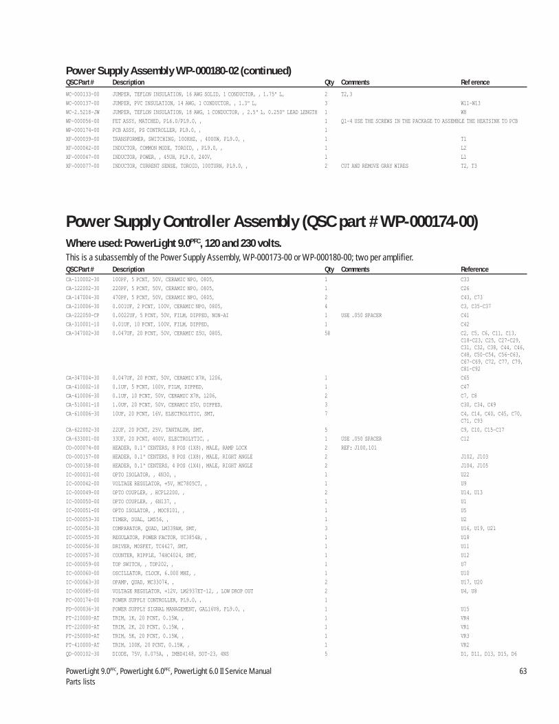
PowerLight 9.0PFC, PowerLight 6.0PFC, PowerLight 6.0 II Service Manual 63Parts lists
WC-000133-00 JUMPER, TEFLON INSULATION, 16 AWG SOLID, 1 CONDUCTOR, , 1.75" L, 2 T2,3
WC-000137-00 JUMPER, PVC INSULATION, 14 AWG, 1 CONDUCTOR, , 1.3" L, 3 W11–W13
WC-2.5218-JW JUMPER, TEFLON INSULATION, 18 AWG, 1 CONDUCTOR, , 2.5" L, 0.250" LEAD LENGTH 1 W8
WP-000056-00 FET ASSY, MATCHED, PL6.0/PL9.0, , 1 Q1-4 USE THE SCREWS IN THE PACKAGE TO ASSEMBLE THE HEATSINK TO PCB
WP-000174-00 PCB ASSY, PS CONTROLLER, PL9.0, , 1
XF-000039-00 TRANSFORMER, SWITCHING, 100KHZ, , 4000W, PL9.0, , 1 T1
XF-000042-00 INDUCTOR, COMMON MODE, TOROID, , PL9.0, , 1 L2
XF-000047-00 INDUCTOR, POWER, , 45UH, PL9.0, 240V, 1 L1
XF-000077-00 INDUCTOR, CURRENT SENSE, TOROID, 100TURN, PL9.0, , 2 CUT AND REMOVE GRAY WIRES T2, T3
Power Supply Controller Assembly (QSC part # WP-000174-00)Where used: PowerLight 9.0PFC, 120 and 230 volts.This is a subassembly of the Power Supply Assembly, WP-000173-00 or WP-000180-00; two per amplifier.QSC Part # Description Qty Comments ReferenceCA-110002-30 100PF, 5 PCNT, 50V, CERAMIC NPO, 0805, 1 C33
CA-122002-30 220PF, 5 PCNT, 50V, CERAMIC NPO, 0805, 1 C26
CA-147004-30 470PF, 5 PCNT, 50V, CERAMIC NPO, 0805, 2 C43, C73
CA-210006-30 0.001UF, 2 PCNT, 100V, CERAMIC NPO, 0805, 4 C3, C35–C37
CA-222050-CP 0.0022UF, 5 PCNT, 50V, FILM, DIPPED, NON-AI 1 USE .050 SPACER C41
CA-310001-10 0.01UF, 10 PCNT, 100V, FILM, DIPPED, 1 C42
CA-347002-30 0.047UF, 20 PCNT, 50V, CERAMIC Z5U, 0805, 58 C2, C5, C6, C11, C13,C18–C23, C25, C27–C29,C31, C32, C38, C44, C46,C48, C50–C54, C56–C63,C67–C69, C72, C77, C79,C81–C92
CA-347004-30 0.047UF, 20 PCNT, 50V, CERAMIC X7R, 1206, 1 C65
CA-410002-10 0.1UF, 5 PCNT, 100V, FILM, DIPPED, 1 C47
CA-410006-30 0.1UF, 10 PCNT, 50V, CERAMIC X7R, 1206, 2 C7, C8
CA-510001-10 1.0UF, 20 PCNT, 50V, CERAMIC Z5U, DIPPED, 3 C30, C34, C49
CA-610006-30 10UF, 20 PCNT, 16V, ELECTROLYTIC, SMT, 7 C4, C14, C40, C45, C70,C71, C93
CA-622002-30 22UF, 20 PCNT, 25V, TANTALUM, SMT, 5 C9, C10, C15–C17
CA-633001-00 33UF, 20 PCNT, 400V, ELECTROLYTIC, , 1 USE .050 SPACER C12
CO-000074-00 HEADER, 0.1" CENTERS, 8 POS (1X8), MALE, RAMP LOCK 2 REF: J100,101
CO-000157-00 HEADER, 0.1" CENTERS, 8 POS (1X8), MALE, RIGHT ANGLE 2 J102, J103
CO-000158-00 HEADER, 0.1" CENTERS, 4 POS (1X4), MALE, RIGHT ANGLE 2 J104, J105
IC-000031-00 OPTO ISOLATOR, , 4N30, , 1 U22
IC-000042-00 VOLTAGE REGULATOR, +5V, MC7805CT, , 1 U9
IC-000049-00 OPTO COUPLER, , HCPL2200, , 2 U14, U13
IC-000050-00 OPTO COUPLER, , 6N137, , 1 U1
IC-000051-00 OPTO ISOLATOR, , MOC8101, , 1 U5
IC-000053-30 TIMER, DUAL, LM556, , 1 U2
IC-000054-30 COMPARATOR, QUAD, LM339AM, SMT, 3 U16, U19, U21
IC-000055-30 REGULATOR, POWER FACTOR, UC3854B, , 1 U18
IC-000056-30 DRIVER, MOSFET, TC4427, SMT, 1 U11
IC-000057-30 COUNTER, RIPPLE, 74HC4024, SMT, 1 U12
IC-000059-00 TOP SWITCH, , TOP202, , 1 U7
IC-000060-00 OSCILLATOR, CLOCK, 6.000 MHZ, , 1 U10
IC-000063-30 OPAMP, QUAD, MC33074, , 2 U17, U20
IC-000085-00 VOLTAGE REGULATOR, +12V, LM2937ET-12, , LOW DROP OUT 2 U4, U8
PC-000174-00 POWER SUPPLY CONTROLLER, PL9.0, , 1
PD-000036-30 POWER SUPPLY SIGNAL MANAGEMENT, GAL16V8, PL9.0, , 1 U15
PT-210000-AT TRIM, 1K, 20 PCNT, 0.15W, , 1 VR4
PT-220000-AT TRIM, 2K, 20 PCNT, 0.15W, , 1 VR1
PT-250000-AT TRIM, 5K, 20 PCNT, 0.15W, , 1 VR3
PT-410000-AT TRIM, 100K, 20 PCNT, 0.15W, , 1 VR2
QD-000102-30 DIODE, 75V, 0.075A, , IMBD4148, SOT-23, 4NS 5 D1, D11, D13, D15, D6
Power Supply Assembly WP-000180-02 (continued)QSC Part # Description Qty Comments Ref erence

64 QSC Audio Products, Inc.TD-000083-00
QD-000103-30 TRANSISTOR NPN, 40V, 0.2A, 0.2W, MMST3904, SOT-23, 7 Q10, Q4, Q5, Q7, Q8, Q9,Q3
QD-000104-30 TRANSISTOR PNP, 40V, 0.2A, 0.2W, MMST3906, SOT-23, 3 Q12, Q2, Q14
QD-000114-30 DIODE ZENER, 150V, , 600W PEAK, P6SMB150AT3, SMB, 1 D3
QD-000115-30 DIODE RECTIFIER ULTRAFAST, 600V, 1A, , MURS160T3, SMB, 75NS 2 D4, D5
QD-000116-30 DIODE RECTIFIER ULTRAFAST, 200V, 1A, , MURS120, SMB, 35NS 4 D2, D8, D9, D10
QD-000136-30 DIODE ZENER, 7.5V, , 0.3W, BZX84C7V5, SOT-23, 1 D7
QD-000163-30 LED RED, , , , , SML-010, VOLTAGE REFERENCE 1 LD1
QD-000168-30 DIODE SCHOTTKY, 70V, 0.2A, , BAS70-04, SOT-23, 2 D14, D12
RE-007502-30 75, 1 PCNT, 1/10W, THICK FILM, 0805, 100V 1 R72
RE-018201-30 182, 1 PCNT, 1/10W, THICK FILM, 0805, 100V 1 R15
RE-020002-30 200, 1 PCNT, 1/10W, THICK FILM, 0805, 100V 1 R2
RE-033205-30 332, 0.1 PCNT, 1/10W, THICK FILM, 0805, 100V 1 R18
RE-090901-30 909, 1 PCNT, 1/10W, THICK FILM, 0805, 100V 1 R37
RE-110002-30 1.00K, 1 PCNT, 1/10W, THICK FILM, 0805, 100V 15 R19, R20, R24, R25, R35,R4, R43, R47, R51, R54, R80, R84, R98, R75, R46
RE-110502-30 1.05K, 1 PCNT, 1/10W, THICK FILM, 0805, 100V 2 R86, R22
RE-115002-30 1.50K, 1 PCNT, 1/10W, THICK FILM, 0805, 100V 4 R16, R17, R7, R70
RE-120002-30 2.00K, 1 PCNT, 1/10W, THICK FILM, 0805, 100V 1 R48
RE-124902-30 2.49K, 1 PCNT, 1/10W, THICK FILM, 0805, 100V 2 R50, R97
RE-130102-30 3.01K, 1 PCNT, 1/10W, THICK FILM, 0805, 100V 2 R13, R14
RE-134802-30 3.48K, 1 PCNT, 1/10W, THICK FILM, 0805, 100V 1 R68
RE-147502-30 4.75K, 1 PCNT, 1/10W, THICK FILM, 0805, 100V 8 R32, R34, R60, R90, R92,R38, R33, R23
RE-160401-30 6.04K, 1 PCNT, 1/10W, THICK FILM, 0805, 100V 4 R36, R44, R45, R79
RE-161900-30 6.19K, 1 PCNT, 1/10W, THICK FILM, 0805, 100V 1 R29
RE-163402-30 6.34K, 1 PCNT, 1/10W, THICK FILM, 0805, 100V 1 R5
RE-178702-30 7.87K, 0.1 PCNT, 1/10W, THICK FILM, 0805, 100V 3 R57, R58, R83
RE-210003-30 10.0K, 1 PCNT, 1/10W, THICK FILM, 0805, 100V 9 R21, R31, R39, R73, R95,R96, R91, R93, R94
RE-212702-30 12.7K, 1 PCNT, 1/10W, THICK FILM, 0805, 100V 3 R41, R52, R78
RE-215002-30 15.0K, 1 PCNT, 1/10W, THICK FILM, 0805, 100V 4 R101, R82, R85, R87
RE-221502-30 21.5K, 1 PCNT, 1/10W, THICK FILM, 0805, 100V 7 R10, R56, R59, R65, R74,R81, R71
RE-224901-30 24.9K, 1 PCNT, 1/10W, THICK FILM, 0805, 100V 2 R9, R11
RE-227401-30 27.4K, 1 PCNT, 1/10W, THICK FILM, 0805, 100V 1 R28
RE-239203-30 39.2K, 0.1 PCNT, 1/10W, THICK FILM, 0805, 100V 1 R55
RE-245302-30 45.3K, 1 PCNT, 1/10W, THICK FILM, 0805, 100V 1 R3
RE-247503-30 47.5K, 1 PCNT, 1/10W, THICK FILM, 0805, 100V 2 R69, R77
RE-310002-30 100K, 1 PCNT, 1/10W, THICK FILM, 0805, 100V 9 R26, R27, R30, R6, R66,R67, R76, R8, R88
RE-314001-30 140K, 1 PCNT, 1/10W, THICK FILM, 0805, 100V 1 R12
RE-375001-30 750K, 1 PCNT, 1/10W, THICK FILM, 0805, 100V 1 R40
XF-000037-00 TRANSFORMER, HOUSEKEEPING, , , , PL9.0, , POWER SUPPLY 1 T1
Display PCB Assembly (QSC part number WP-000176-00)Where used: All models, all voltagesThis is a subassembly of each model’s respective chassis assembly; one per amplifier.QSC Part # Description Qty Comments Ref erenceCA-147001-10 470PF, 10 PCNT, 100V, CERAMIC Y5E, DISC, 2 C502, C602
CA-410004-10 0.1UF, 20 PCNT, 50V, CERAMIC Z5U, DIPPED, 2 C507, C607
CA-422001-10 0.22UF, 5 PCNT, 50V, FILM, DIPPED, LOW PROFILE 4 C501, C505, C601, C605
CA-647003-10 47UF, 10 PCNT, 10V, ELECTROLYTIC, , NON-POLAR LOW PROFILE 2 C503, C603
CA-710035-BE 100UF, 20 PCNT, 35V, ELECTROLYTIC, , NON-AI 4 C504, C506, C604, C606
CO-000048-CO HEADER, 0.1" CENTERS, 16 POS (2X8), MALE, TERMINAL STRIP GOLD 2 J501, J601
IC-000072-OP OPAMP, DUAL, TL072, , 2 U501, U601
PC-000176-00 DISPLAY, PL9.0, , 1
PL-000127-00 SPACER, T-1 LED, 0.48", PLASTIC, BLACK, 14 ASSEMBLE W/ QD-000052-00, QD-000053-00, QD-000054-0
Power Supply Controller Assembly WP-000174-00 (continued)QSC Part # Description Qty Comments Ref erence

PowerLight 9.0PFC, PowerLight 6.0PFC, PowerLight 6.0 II Service Manual 65Parts lists
PT-310000-CR GAIN, 10K, 20 PCNT, 0.2W, 11 DETENT, 2 R509, R609
QD-000052-00 LED GREEN, , , , , T-1, DIFFUSED 4 LD503, LD603, LD507,LD607
QD-000053-00 LED YELLOW, , , , , T-1, 6 LD502, LD505, LD506,LD602, LD605, LD606
QD-000054-00 LED RED, , , , , T-1, 4 LD501, LD504, LD601,LD604
QD-000062-10 TRANSISTOR NPN, 40V, 0.2A, 1.5W, 2N3904, TO-92, 4 Q505, Q507, Q605, Q607
QD-000063-10 TRANSISTOR PNP, 40V, 0.2A, 1.5W, 2N3906, TO-92, 12 Q501–Q504, Q506, Q508,Q601–Q604, Q606, Q608
QD-004148-DX DIODE, 75V, 0.075A, , 1N4148, DO-35, 4NS 6 D501–D503, D601–D603
RE-004751-BM 47.5, 1 PCNT, 1/4W, METAL FILM, , 4 R513, R517, R613, R617
RE-027005-BC 270, 5 PCNT, 1/4W, CARBON FILM, , 4 R503, R516, R603, R616
RE-047501-BM 475, 1 PCNT, 1/4W, METAL FILM, , 6 R514, R518, R519, R614,R618, R619
RE-064901-BM 649, 1 PCNT, 1/4W, METAL FILM, , 2 R515, R615
RE-082005-BC 820, 5 PCNT, 1/4W, CARBON FILM, , 2 R520, R620
RE-122101-BM 2.21K, 1 PCNT, 1/4W, METAL FILM, , 2 R508, R608
RE-134801-BM 3.48K, 1 PCNT, 1/4W, METAL FILM, , 2 R512, R612
RE-145301-10 4.53K, 1 PCNT, 1/8W, METAL FILM, , 2 R507, R607
RE-147501-AM 4.75K, 1 PCNT, 1/8W, METAL FILM, , 6 R504–R506, R604–R606
RE-220001-BM 20.0K, 1 PCNT, 1/4W, METAL FILM, , 4 R510, R511, R611, R610
SW-000042-00 SWITCH, DPDT, PUSH-LOCK, PCB MOUNT VERTICAL* 2 SW501, SW601
*THE SWITCH WHITE SHAFT SHOULD BE ON THE LOWER END OF THE BOARD
Display PCB Assembly WP-000176-00 (continued)QSC Part # Description Qty Comments Ref erence
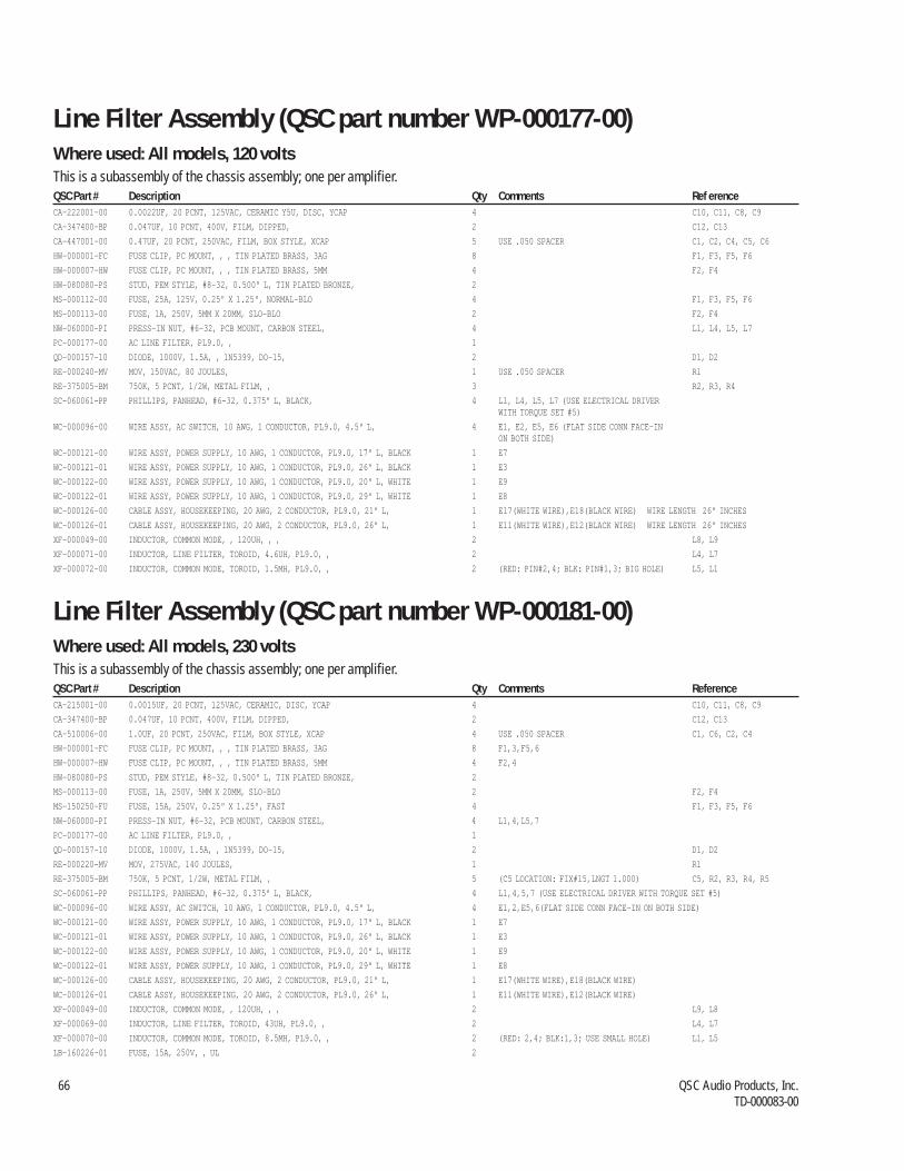
66 QSC Audio Products, Inc.TD-000083-00
Line Filter Assembly (QSC part number WP-000181-00)Where used: All models, 230 voltsThis is a subassembly of the chassis assembly; one per amplifier.QSC Part # Description Qty Comments ReferenceCA-215001-00 0.0015UF, 20 PCNT, 125VAC, CERAMIC, DISC, YCAP 4 C10, C11, C8, C9
CA-347400-BP 0.047UF, 10 PCNT, 400V, FILM, DIPPED, 2 C12, C13
CA-510006-00 1.0UF, 20 PCNT, 250VAC, FILM, BOX STYLE, XCAP 4 USE .050 SPACER C1, C6, C2, C4
HW-000001-FC FUSE CLIP, PC MOUNT, , , TIN PLATED BRASS, 3AG 8 F1,3,F5,6
HW-000007-HW FUSE CLIP, PC MOUNT, , , TIN PLATED BRASS, 5MM 4 F2,4
HW-080080-PS STUD, PEM STYLE, #8-32, 0.500" L, TIN PLATED BRONZE, 2
MS-000113-00 FUSE, 1A, 250V, 5MM X 20MM, SLO-BLO 2 F2, F4
MS-150250-FU FUSE, 15A, 250V, 0.25" X 1.25", FAST 4 F1, F3, F5, F6
NW-060000-PI PRESS-IN NUT, #6-32, PCB MOUNT, CARBON STEEL, 4 L1,4,L5,7
PC-000177-00 AC LINE FILTER, PL9.0, , 1
QD-000157-10 DIODE, 1000V, 1.5A, , 1N5399, DO-15, 2 D1, D2
RE-000220-MV MOV, 275VAC, 140 JOULES, 1 R1
RE-375005-BM 750K, 5 PCNT, 1/2W, METAL FILM, , 5 (C5 LOCATION: FIX#15,LNGT 1.000) C5, R2, R3, R4, R5
SC-060061-PP PHILLIPS, PANHEAD, #6-32, 0.375" L, BLACK, 4 L1,4,5,7 (USE ELECTRICAL DRIVER WITH TORQUE SET #5)
WC-000096-00 WIRE ASSY, AC SWITCH, 10 AWG, 1 CONDUCTOR, PL9.0, 4.5" L, 4 E1,2,E5,6(FLAT SIDE CONN FACE-IN ON BOTH SIDE)
WC-000121-00 WIRE ASSY, POWER SUPPLY, 10 AWG, 1 CONDUCTOR, PL9.0, 17" L, BLACK 1 E7
WC-000121-01 WIRE ASSY, POWER SUPPLY, 10 AWG, 1 CONDUCTOR, PL9.0, 26" L, BLACK 1 E3
WC-000122-00 WIRE ASSY, POWER SUPPLY, 10 AWG, 1 CONDUCTOR, PL9.0, 20" L, WHITE 1 E9
WC-000122-01 WIRE ASSY, POWER SUPPLY, 10 AWG, 1 CONDUCTOR, PL9.0, 29" L, WHITE 1 E8
WC-000126-00 CABLE ASSY, HOUSEKEEPING, 20 AWG, 2 CONDUCTOR, PL9.0, 21" L, 1 E17(WHITE WIRE),E18(BLACK WIRE)
WC-000126-01 CABLE ASSY, HOUSEKEEPING, 20 AWG, 2 CONDUCTOR, PL9.0, 26" L, 1 E11(WHITE WIRE),E12(BLACK WIRE)
XF-000049-00 INDUCTOR, COMMON MODE, , 120UH, , , 2 L9, L8
XF-000069-00 INDUCTOR, LINE FILTER, TOROID, 43UH, PL9.0, , 2 L4, L7
XF-000070-00 INDUCTOR, COMMON MODE, TOROID, 8.5MH, PL9.0, , 2 (RED: 2,4; BLK:1,3; USE SMALL HOLE) L1, L5
LB-160226-01 FUSE, 15A, 250V, , UL 2
Line Filter Assembly (QSC part number WP-000177-00)Where used: All models, 120 voltsThis is a subassembly of the chassis assembly; one per amplifier.QSC Part # Description Qty Comments Ref erenceCA-222001-00 0.0022UF, 20 PCNT, 125VAC, CERAMIC Y5U, DISC, YCAP 4 C10, C11, C8, C9
CA-347400-BP 0.047UF, 10 PCNT, 400V, FILM, DIPPED, 2 C12, C13
CA-447001-00 0.47UF, 20 PCNT, 250VAC, FILM, BOX STYLE, XCAP 5 USE .050 SPACER C1, C2, C4, C5, C6
HW-000001-FC FUSE CLIP, PC MOUNT, , , TIN PLATED BRASS, 3AG 8 F1, F3, F5, F6
HW-000007-HW FUSE CLIP, PC MOUNT, , , TIN PLATED BRASS, 5MM 4 F2, F4
HW-080080-PS STUD, PEM STYLE, #8-32, 0.500" L, TIN PLATED BRONZE, 2
MS-000112-00 FUSE, 25A, 125V, 0.25" X 1.25", NORMAL-BLO 4 F1, F3, F5, F6
MS-000113-00 FUSE, 1A, 250V, 5MM X 20MM, SLO-BLO 2 F2, F4
NW-060000-PI PRESS-IN NUT, #6-32, PCB MOUNT, CARBON STEEL, 4 L1, L4, L5, L7
PC-000177-00 AC LINE FILTER, PL9.0, , 1
QD-000157-10 DIODE, 1000V, 1.5A, , 1N5399, DO-15, 2 D1, D2
RE-000240-MV MOV, 150VAC, 80 JOULES, 1 USE .050 SPACER R1
RE-375005-BM 750K, 5 PCNT, 1/2W, METAL FILM, , 3 R2, R3, R4
SC-060061-PP PHILLIPS, PANHEAD, #6-32, 0.375" L, BLACK, 4 L1, L4, L5, L7 (USE ELECTRICAL DRIVERWITH TORQUE SET #5)
WC-000096-00 WIRE ASSY, AC SWITCH, 10 AWG, 1 CONDUCTOR, PL9.0, 4.5" L, 4 E1, E2, E5, E6 (FLAT SIDE CONN FACE-INON BOTH SIDE)
WC-000121-00 WIRE ASSY, POWER SUPPLY, 10 AWG, 1 CONDUCTOR, PL9.0, 17" L, BLACK 1 E7
WC-000121-01 WIRE ASSY, POWER SUPPLY, 10 AWG, 1 CONDUCTOR, PL9.0, 26" L, BLACK 1 E3
WC-000122-00 WIRE ASSY, POWER SUPPLY, 10 AWG, 1 CONDUCTOR, PL9.0, 20" L, WHITE 1 E9
WC-000122-01 WIRE ASSY, POWER SUPPLY, 10 AWG, 1 CONDUCTOR, PL9.0, 29" L, WHITE 1 E8
WC-000126-00 CABLE ASSY, HOUSEKEEPING, 20 AWG, 2 CONDUCTOR, PL9.0, 21" L, 1 E17(WHITE WIRE),E18(BLACK WIRE) WIRE LENGTH 26" INCHES
WC-000126-01 CABLE ASSY, HOUSEKEEPING, 20 AWG, 2 CONDUCTOR, PL9.0, 26" L, 1 E11(WHITE WIRE),E12(BLACK WIRE) WIRE LENGTH 26" INCHES
XF-000049-00 INDUCTOR, COMMON MODE, , 120UH, , , 2 L8, L9
XF-000071-00 INDUCTOR, LINE FILTER, TOROID, 4.6UH, PL9.0, , 2 L4, L7
XF-000072-00 INDUCTOR, COMMON MODE, TOROID, 1.5MH, PL9.0, , 2 (RED: PIN#2,4; BLK: PIN#1,3; BIG HOLE) L5, L1
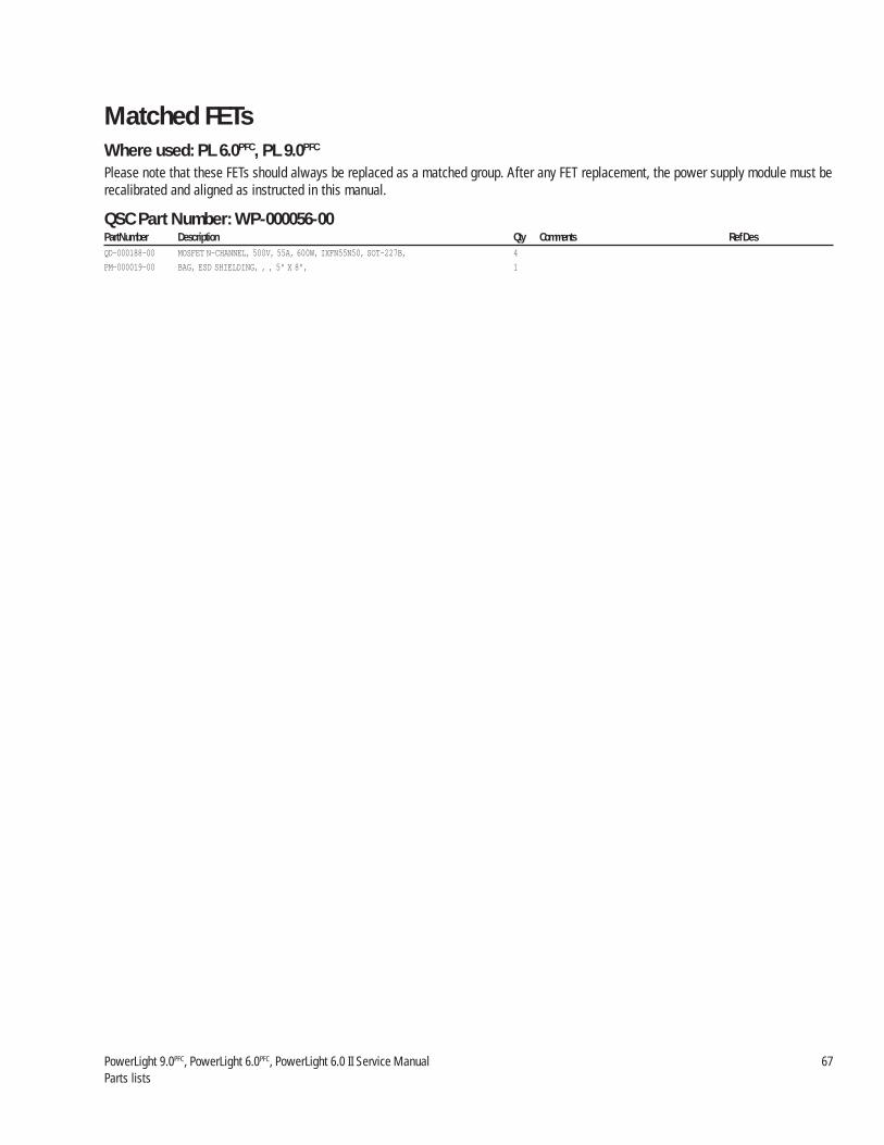
PowerLight 9.0PFC, PowerLight 6.0PFC, PowerLight 6.0 II Service Manual 67Parts lists
Matched FETsWhere used: PL 6.0PFC, PL 9.0PFC
Please note that these FETs should always be replaced as a matched group. After any FET replacement, the power supply module must berecalibrated and aligned as instructed in this manual.
QSC Part Number: WP-000056-00Part Number Description Qty Comments Ref DesQD-000188-00 MOSFET N-CHANNEL, 500V, 55A, 600W, IXFN55N50, SOT-227B, 4
PM-000019-00 BAG, ESD SHIELDING, , , 5" X 8", 1

68 QSC Audio Products, Inc.TD-000083-00
5. Schematic diagrams

Technical Service Manual 69PowerLight 6.0 II, PowerLight 6.0PFC, and PowerLight 9.0PFC
220pC1
PowerLight 6.0PFC
PowerLight 6.0 IIPowerLight 9.0PFC
Input Daughterboard

70 QSC Audio Products, Inc.TD-000083-00
SW1:3
SW1:4 SW1:1
SW1:2
U400:2
TL072
U400:1
TL072
220p
C400
220p
C402
220p
C300
220p
C302
U300:2
TL072
U300:1
TL072
E3
E2
PowerLight 6.0PFC
PowerLight 6.0 IIInput Board
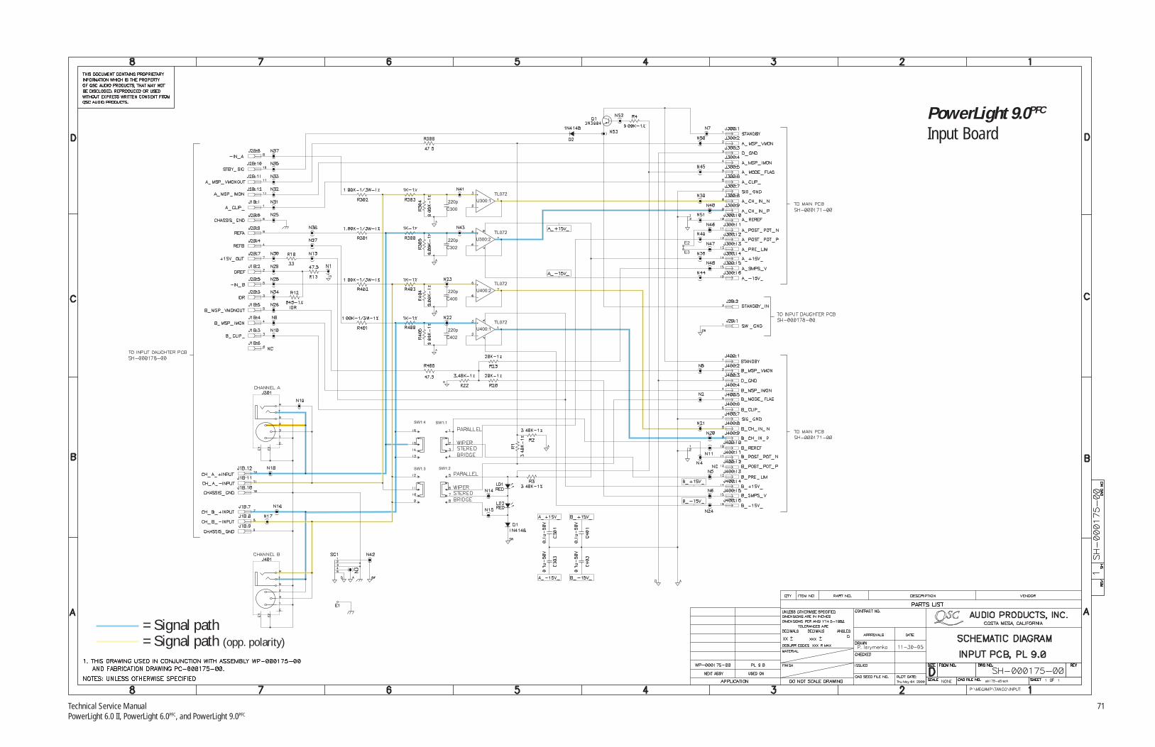
Technical Service Manual 71PowerLight 6.0 II, PowerLight 6.0PFC, and PowerLight 9.0PFC
= Signal path= Signal path (opp. polarity)
SW1:3
SW1:4 SW1:1
SW1:2
U400:2
TL072
U400:1
TL072
220p
C400
220p
C402
220p
C300
220p
C302
U300:2
TL072
U300:1
TL072
E3
E2
PowerLight 9.0PFC
Input Board

72 QSC Audio Products, Inc.TD-000083-00
15 V
Node N289“Ana gnd”
pp. 5A7 & 7D415 V
Node N289“Ana gnd”
pp. 5A7 & 7D4
9
10
11
12
13
14
15
16
22u-25V
C68
22u-25V
C63
PRE_LIMPRE_LIM
-15V_-15V_
+15V_+15V_
SMPS_VSMPS_V
POST_POT_PPOST_POT_P
POST_POT_NPOST_POT_N
CH_IN_PCH_IN_P
B1_N
B1_P
REREF
-POL-
+POL+
PRE_LIM
SMPS_ON
REREF
PROTECT
LOSS_OF_FEEDBACK
8
7
6
4
3
2
1
CLIP_
MSP_IMON
MSP_VMON
STANDBY
MSP_VMON
MSP_IMONMSP_IMON
D_GND
MSP_VMON
STANDBY
SIG_GNDSIG_GND
MODE_FLAG
CH_IN_NCH_IN_N
5
3+
2-
1
280 KHz LPF
+POL+
-POL-
+15V
5
4
3
2
1
I_SET
PSENABLE_K
PSENABLE_A
8
7
6
SHED_V SHED_V
PWR_GND
PWR_GND
PSENABLE_K
PSENABLE_A
I_SET
CLIP
10J6:10
11J6:11
12J6:12
13J6:13
+15V
V_MON
14J6:14
15J6:15
16J6:16
CLIP_FEED
47-10NP-10%
C88
STANDBY_LED
7J6:7
8J6:8
1J6:1
2J6:2
4J6:4
3J6:3
5J6:5
6J6:6
9J6:9
+POL+
VP
VN
-POL-
VN
VP
STANDBY_LED
POT_TOP
POST_POT_P
POST_POT_N
SIG_GND
SIG_GND
REREF
PROTECT
+15V
V_MON
PWR_GND
CLIP_FEED
CLIPCLIP
PWR_GND
PowerLight 6.0PFC
PowerLight 6.0 IIRouting

Technical Service Manual 73PowerLight 6.0 II, PowerLight 6.0PFC, and PowerLight 9.0PFC
15 V
Node N289“Ana gnd”
pp. 5A7 & 7D415 V
Node N289“Ana gnd”
pp. 5A7 & 7D4
9
10
11
12
13
14
15
16
22u-25V
C68
22u-25V
C63
PRE_LIMPRE_LIM
-15V_-15V_
+15V_+15V_
SMPS_VSMPS_V
POST_POT_PPOST_POT_P
POST_POT_NPOST_POT_N
CH_IN_PCH_IN_P
B1_N
B1_P
REREF
-POL-
+POL+
PRE_LIM
SMPS_ON
REREF
PROTECT
LOSS_OF_FEEDBACK
8
7
6
4
3
2
1
CLIP_
MSP_IMON
MSP_VMON
STANDBY
MSP_VMON
MSP_IMONMSP_IMON
D_GND
MSP_VMON
STANDBY
SIG_GNDSIG_GND
MODE_FLAG
CH_IN_NCH_IN_N
5
3+
2-
1
280 KHz LPF
+POL+
-POL-
+15V
5
4
3
2
1
I_SET
PSENABLE_K
PSENABLE_A
8
7
6
SHED_V SHED_V
PWR_GND
PWR_GND
PSENABLE_K
PSENABLE_A
I_SET
CLIP
10J6:10
11J6:11
12J6:12
13J6:13
+15V
V_MON
14J6:14
15J6:15
16J6:16
CLIP_FEED
47-10NP-10%
C88
STANDBY_LED
7J6:7
8J6:8
1J6:1
2J6:2
4J6:4
3J6:3
5J6:5
6J6:6
9J6:9
+POL+
VP
VN
-POL-
VN
VP
STANDBY_LED
POT_TOP
POST_POT_P
POST_POT_N
SIG_GND
SIG_GND
REREF
PROTECT
+15V
V_MON
PWR_GND
CLIP_FEED
CLIPCLIP
PWR_GND
PowerLight 9.0PFC
Routing

74 QSC Audio Products, Inc.TD-000083-00
= Signal path
A_VN
A_+15V
A_V_MON
A_PROTECT
A_CLIP
PWR_GND
PWR_GND
A_CLIP_FEED
J501:16
J501:9
J501:10
J501:11
J501:12
J501:13
J501:14
J501:15
+POL+A_POT_TOP
A_POST_POT_N
A_POST_POT_P
SIG_GND
A_STANDBY_LED
SIG_GND
A_VP
A_REREFJ501:2
J501:3
J501:4
J501:5
J501:6
J501:7
J501:8
-POL-
J501:1
R5
09
10K
-DE
T-T
HR
U-P
CB
TL072
U501:1
TL072
U501:2+POL+
PowerLight 6.0PFC
PowerLight 6.0 IIPowerLight 9.0PFC
Display board, Channel A

Technical Service Manual 75PowerLight 6.0 II, PowerLight 6.0PFC, and PowerLight 9.0PFC
= Signal path
B_STANDBY_LED
SIG_GND
B_+15V
B_V_MON
B_PROTECT
PWR_GND
PWR_GND
B_CLIP_FEED
B_CLIP
J601:16
J601:13
J601:14
J601:15
J601:9
J601:10
J601:11
J601:12
J601:6
J601:7
J601:8
B_VP
B_VN
J601:2
J601:3
J601:4
J601:5
J601:1
R6
09
10K
-DE
T-T
HR
U-P
CB
+POL+
-POL-
+POL+
B_POT_TOP
B_POST_POT_N
B_POST_POT_P
SIG_GND
B_REREF
TL072
U601:2
TL072
U601:1
PowerLight 6.0PFC
PowerLight 6.0 IIPowerLight 9.0PFC
Display board, Channel B

76 QSC Audio Products, Inc.TD-000083-00
Limiter is shown in "fast clip-tracking"mode.To convert to a slow attack/release limiter,open the 3 places shown shorted with lines,and make the connection shown by thearrow line.
VP
VN
GAIN_RETARD
Gain = 1.67
5+
6-
7
REREF
-POL-
PRE_LIM
+15V_
VP
11
6
3+
8
7 5
1
4-
2
84
-POL-
VP
-15V_
3+
2-
1
VP
CLIP_FEED
5+
6-
7
CLIP
5V=187V
3+
2-
1
_N_STEP
Values shown preclip a fixed5 volts below the rails up to15 amps of output current.After that, preclip advances120 mV per ampere output,for 12v preclip at 70 amps.
Gain = 1/37.5
I_MON
_V200
MUTE_BOP
3+
2-
1
0.84 atten.
3+
2-
1
5+
6-
7
Positive = Clip
VN
VP
With values shown, the effectivestep switch time delay is 4usflat out to 50 KHz.
CLAMP_SIG
14+
9
10 12
16
13-
15
-POL-
5+
6-
7
3+
2-
1
+POL+
N_ISENSE
VN
VP
P_ISENSE
DIFF_AMP_BIAS
-POL-
_BOP
_SPK_GND
_SPK
Closed loop gain=37.5 or 31.5 dB
DN
_D
RV
LOSS_OF_FEEDBACK
VN
UP
_D
RV
PowerLight 6.0PFC
PowerLight 6.0 IISignal Processing
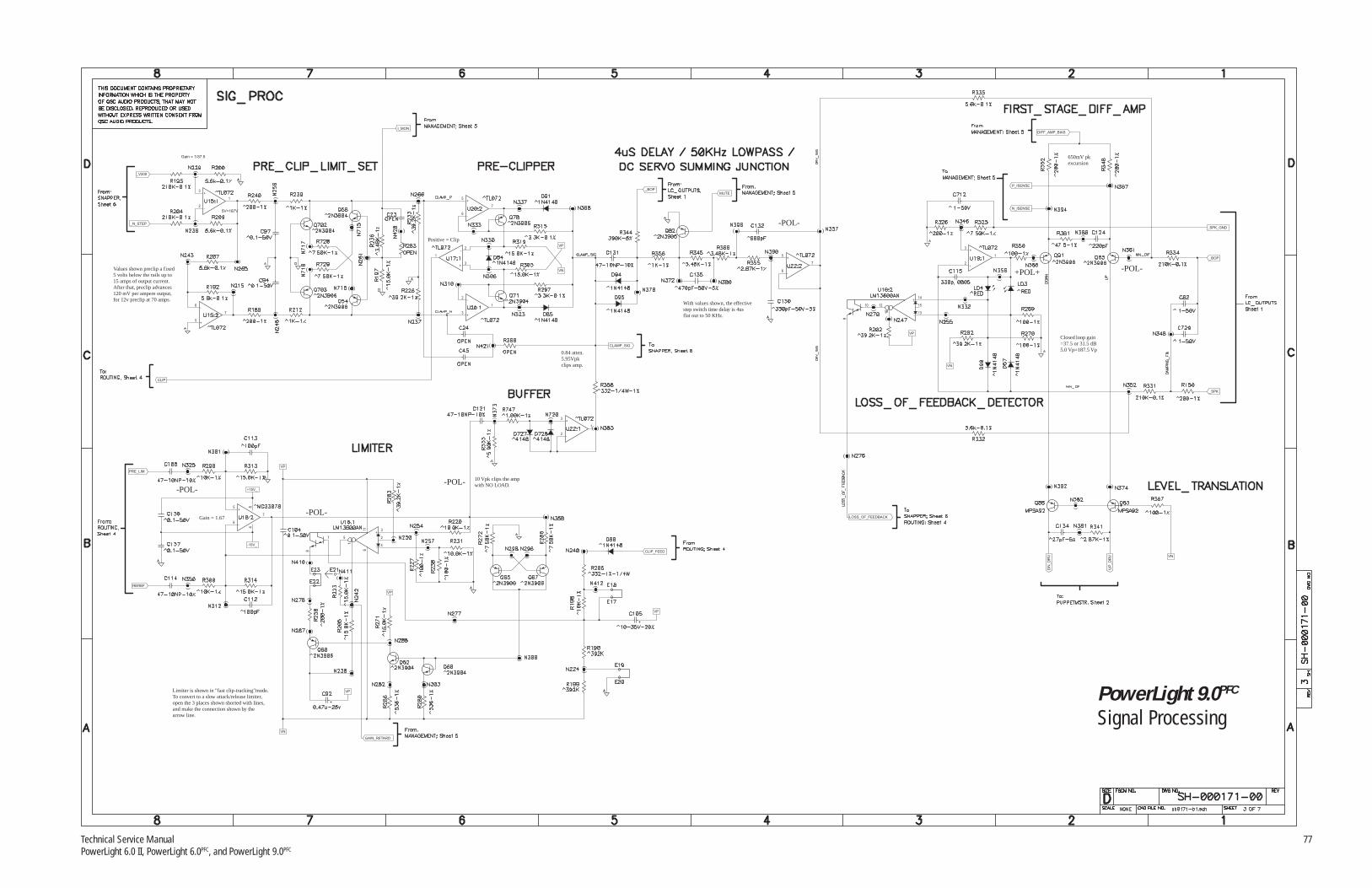
Technical Service Manual 77PowerLight 6.0 II, PowerLight 6.0PFC, and PowerLight 9.0PFC
Limiter is shown in "fast clip-tracking"mode.To convert to a slow attack/release limiter,open the 3 places shown shorted with lines,and make the connection shown by thearrow line.
VP
VN
GAIN_RETARD
Gain = 1.67
5+
6-
7
REREF
-POL-
PRE_LIM
+15V_
VP
11
6
3+
8
7 5
1
4-
2
84
-POL-
VP
-15V_
3+
2-
1
10 Vpk clips the ampwith NO LOAD.-POL-
VP
CLIP_FEED
5+
6-
7
CLIP
5V=187V
3+
2-
1
_N_STEP
Values shown preclip a fixed5 volts below the rails up to15 amps of output current.After that, preclip advances120 mV per ampere output,for 12v preclip at 70 amps.
Gain = 1/37.5
I_MON
_V200
MUTE_BOP
0.84 atten.5.95Vpkclips amp.
3+
2-
1
3+
2-
1
5+
6-
7
Positive = Clip
VN
VP
With values shown, the effectivestep switch time delay is 4usflat out to 50 KHz.
CLAMP_SIG
14+
9
10 12
16
13-
15
-POL-
5+
6-
7
+POL+
3+
2-
1
N_ISENSE
VN
VP
P_ISENSE
DIFF_AMP_BIAS
650mV pkexcursion
Closed loop gain=37.5 or 31.5 dB5.0 Vp=187.5 Vp
-POL-
_BOP
_SPK_GND
_SPK
DN
_D
RV
LOSS_OF_FEEDBACK
VN
UP
_D
RV
PowerLight 9.0PFC
Signal Processing

78 QSC Audio Products, Inc.TD-000083-00
27 V
3+
2-
1
3 volts here signifies50 amps output, soload is likely 2 ohms.
VN
3+
2-
1
I_MON
SHED_V
_N_STEP
_V50
VN
PROTECT
3+
2-
1
VN
VN
VN
5+
6-
7
VN
G
D SV_MON
LOSS_OF_FEEDBACK
CLAMP_SIG3
+
2-
1
_N_STEP
5+
6-
7
NOTE: This opamp must notclamp its input terminalstogether. TL072 or EQIV!!!
_V100
_N_STEP
_V150
5+
6-
7
VN
5+
6-
7
5+
6-
7
VN
3+
2-
1
DS
G
Clamps caps to 48-54V
DS
G
_V200
2
1
5
4
3
_V100
_V150
C33
22u-25V
84
84
VN VN
VP
C1
9
22
u-2
5V
22
u-2
5V
C4
8
22
u-2
5V
C4
9
C3
0
22
u-2
5V
C3
1
22
u-2
5V
84
84
84
DS
G
_V50
B4_P
B4_N
_VTOP
_VBOT
_N_STEP
PowerLight 6.0PFC
PowerLight 6.0 IIClass H Step Drivers

Technical Service Manual 79PowerLight 6.0 II, PowerLight 6.0PFC, and PowerLight 9.0PFC
27 V
3+
2-
1
3 volts here signifies50 amps output, soload is likely 2 ohms.
VN
3+
2-
1
I_MON
SHED_V
_N_STEP
_V50
VN
PROTECT
3+
2-
1
VN
VN
VN
5+
6-
7
VN
G
D SV_MON
LOSS_OF_FEEDBACK
CLAMP_SIG
_N_STEP
3+
2-
1
5+
6-
7
NOTE: This opamp must notclamp its input terminalstogether. TL072 or EQIV!!!
_V100
_N_STEP
_V150
5+
6-
7
VN
5+
6-
7
5+
6-
7
VN
3+
2-
1
DS
G
Clamps caps to 48-54V
DS
G
_V200
2
1
5
4
3
_V100
_V150
C33
22u-25V
84
84
VN VN
VP
C1
9
22
u-2
5V
22
u-2
5V
C4
8
22
u-2
5V
C4
9
C3
0
22
u-2
5V
C3
1
22
u-2
5V
84
84
84
DS
G
_V50
B4_P
B4_N
_VTOP
_VBOT
_N_STEP
PowerLight 9.0PFC
Class H Step Drivers

80 QSC Audio Products, Inc.TD-000083-00
12.4 V
40 V
Node N182“B3_P” (through 150 resistor)Ω
p. 1C1
C12622u-25V
B3_N
_VBOT
22
u-2
5V
C1
25
CW
CC
W
W
5
U21:3
CA3054M96
14
13
4
3
2
1
CA3054M96
U21:1
DN_DRV
HOT
22
u-2
5V
C1
29
_BOP
PM_REF
IX3
DR
3
DR
1
IX1
_BGND
_V
BO
T
_V
TO
P
_B
GN
D
_B
OP
_V
TO
P
_V
BO
T
_B
GN
D
_B
OP
IX2
DR
2
DR
4
I X4
UP_DRV
7
6
12
11
9
8
CA3054M96
U21:2
PowerLight 6.0PFC
PowerLight 6.0 IIPuppetmaster (Class BCurrent Steering)
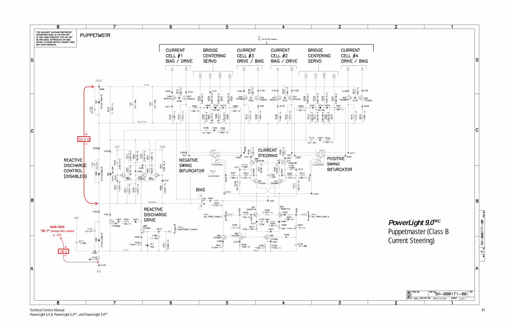
Technical Service Manual 81PowerLight 6.0 II, PowerLight 6.0PFC, and PowerLight 9.0PFC
12.4 V
40 V
Node N182“B3_P” (through 150 resistor)Ω
p. 1C1
C12622u-25V
B3_N
_VBOT
22
u-2
5V
C1
25
CW
CC
WW
5
U21:3
CA3054M96
14
13
4
3
2
1
CA3054M96
U21:1
DN_DRV
HOT
22
u-2
5V
C1
29
_BOP
PM_REF
IX3
DR
3
DR
1
IX1
_BGND
_V
BO
T
_V
TO
P
_B
GN
D
_B
OP
_V
TO
P
_V
BO
T
_B
GN
D
_B
OP
IX2
DR
2
DR
4
IX4
UP_DRV
7
6
12
11
9
8
CA3054M96
U21:2
PowerLight 9.0PFC
Puppetmaster (Class BCurrent Steering)

82 QSC Audio Products, Inc.TD-000083-00
20 V 30 V
40 V
Node N105“B3_N”
pp. 2A7 & 7B5
DR3
IX3
11
4
EL2257C
U14:3
B3_P
1+
14-
13
32
C
E
U14:1
EL2257C 7+
8-
9
56
C
E
U14:2
EL2257C
DS
G
DS
G
_VBOT
PM_REF
DR2
IX2
11
4
EL2257CU11:3
B2_N
B2_P
1+
14-
13
32
C
E
U11:1
EL2257C 7+
8-
9
56
C
E
U11:2
EL2257C
_VTOP
_BOP
DS
G
DS
G
This connects tochassis gnd at therear panel.
1 2
_SPK
_SPK_GND
1
2_BGND
DS
G
DS
G
7+
8-
9
56
C
EEL2257C
U12:2
1+
14-
13
32
C
E
U12:1
EL2257C
IX1
DR1
11
4
U12:3
EL2257C
B1_P
B1_N
ITEM NO.QTY PART NO. DESCRIPTION VENDOR
7+
8-
9
56
C
E
U13:2
EL2257C
DS
G
1+
14-
13
32
C
EEL2257C
U13:1
DS
G
11
4
U13:3
EL2257C
B3_P
IX4
DR4
PowerLight 6.0PFC
PowerLight 6.0 IIOutput Power Section

Technical Service Manual 83PowerLight 6.0 II, PowerLight 6.0PFC, and PowerLight 9.0PFC
20 V 30 V
40 V
Node N105“B3_N”
pp. 2A7 & 7B5
DR3
IX3
11
4
EL2257C
U14:3
B3_P
1+
14-
13
32
C
E
U14:1
EL2257C
DS
G
7+
8-
9
56
C
E
U14:2
EL2257C
DS
G
_VBOT
PM_REF
DR2
IX2
11
4
EL2257CU11:3
B2_N
B2_P
1+
14-
13
32
C
E
U11:1
EL2257C 7+
8-
9
56
C
E
U11:2
EL2257C
_VTOP
_BOP
DS
G
DS
G
This connects tochassis gnd at therear panel.
1 2
_SPK
_SPK_GND
1
2_BGND
DS
G
DS
G
7+
8-
9
56
C
EEL2257C
U12:2
1+
14-
13
32
C
E
U12:1
EL2257C
IX1
DR1
11
4
U12:3
EL2257C
B1_P
B1_N
ITEM NO.QTY PART NO. DESCRIPTION VENDOR
DS
G
7+
8-
9
56
C
E
U13:2
EL2257C 1+
14-
13
32
C
EEL2257C
U13:1
DS
G
11
4
U13:3
EL2257C
B3_P
IX4
DR4
PowerLight 9.0PFC
Output Power Section

84 QSC Audio Products, Inc.TD-000083-00
15 VNode N273“+15V_”
p. 4B7
15 V
Node N284“-15V_”p. 4B7
11 V
11 VHOT=250uA@ 80 deg C.
The "HOT" threshold is 80°CCutback begins at 100°C andfull shutdown happens at 110°C.(±3 degrees)
3+
2-
1
U12.5V-1%
VP
HOT
5V = 100 deg C.
C5
5
22
u-2
5V4
3
Fan idles at 10V upto 60C. From 60C to80C fan ramps from10V to 24V. At 85Cfan V = 28V MAX.(Note that SMPS canalso speed fan up.)
B3_N
_N_STEP
FAN_N
SN
AP
PE
RP
TC
5+
6-
7
2
3
1VP
GAIN_RETARD
VN
1
2
Nominal I_SET = 3ma to 5ma.Amp is fully on at I_SET>1ma.Above 3ma fan is unaccellerated.From 3ma to 1ma speed rises.Below 1ma fan speed reducesback linearily to normal speed.
I_SET
_V50
VP
Current gain: 22,460.3.0 mA total set curentresults in 68A peak output.Minumum at full cut-back is250 uA or 5.6A output.
600ms delay to enable audio.200ms delay to disable audio.
22
u-2
5V
C11
7
SMPS_ON
DIFF_AMP_BIAS
MUTE
VN
G
DS
PROTECT
_BOP
VN
VP
PSENABLE_K
PSENABLE_A
STANDBY_LED
_BOP
_BGND
Total Gain = 16.85dB
5+
6-
7
5+
6-
7
3+
2-
1
Gain = 1/37.5
5+
6-
7
-POL-
P_ISENSE
V_MON
MSP_VMON
_SPK_GND
N_ISENSE
MSP_IMON
I_MON
PowerLight 6.0PFC
PowerLight 6.0 IIManagement/Protection

Technical Service Manual 85PowerLight 6.0 II, PowerLight 6.0PFC, and PowerLight 9.0PFC
15 VNode N273“+15V_”
p. 4B7
15 V
Node N284“-15V_”p. 4B7
11 V
11 VHOT=250uA@ 80 deg C.
The "HOT" threshold is 80CCutback begins at 100C andfull shutdown happens at 110C.(+/- 3 degrees)
3+
2-
1
U12.5V-1%
VP
HOT
5V = 100 deg C.
C5
5
22
u-2
5V4
3
Fan idles at 10V upto 60C. From 60C to80C fan ramps from10V to 24V. At 85Cfan V = 28V MAX.(Note that SMPS canalso speed fan up.)
B3_N
_N_STEP
FAN_N
SN
AP
PE
RP
TC
5+
6-
7
2
3
1VP
GAIN_RETARD
VN
1
2
Nominal I_SET = 3ma to 5ma.Amp is fully on at I_SET>1ma.Above 3ma fan is unaccellerated.From 3ma to 1ma speed rises.Below 1ma fan speed reducesback linearily to normal speed.
I_SET
_V50
VP
Current gain: 22,460.3.6 mA total set curentresults in 81A peak output.Minumum at full cut-back is250 uA or 5.6A output.
600ms delay to enable audio.200ms delay to disable audio.
22
u-2
5V
C11
7
SMPS_ON
DIFF_AMP_BIAS
MUTE
VN
G
DS
PROTECT
_BOP
VN
VP
PSENABLE_K
PSENABLE_A
STANDBY_LED
_BOP
_BGND
70A = 5V>5V = Current Limiting.
Total Gain = 16.85dB
5+
6-
7
5+
6-
7
3+
2-
1
Gain = 1/37.5
5+
6-
7
186V = 5V
-POL-
P_ISENSE
V_MON
MSP_VMON
_SPK_GND
N_ISENSE
MSP_IMON
I_MON
PowerLight 9.0PFC
Management/Protection

86 QSC Audio Products, Inc.TD-000083-00
PowerLight 6.0PFC
PowerLight 6.0 IIPowerLight 9.0PFC
Line Filter, 120 volts

Technical Service Manual 87PowerLight 6.0 II, PowerLight 6.0PFC, and PowerLight 9.0PFC
PowerLight 6.0PFC
PowerLight 6.0 IIPowerLight 9.0PFC
Line Filter, 230 volts
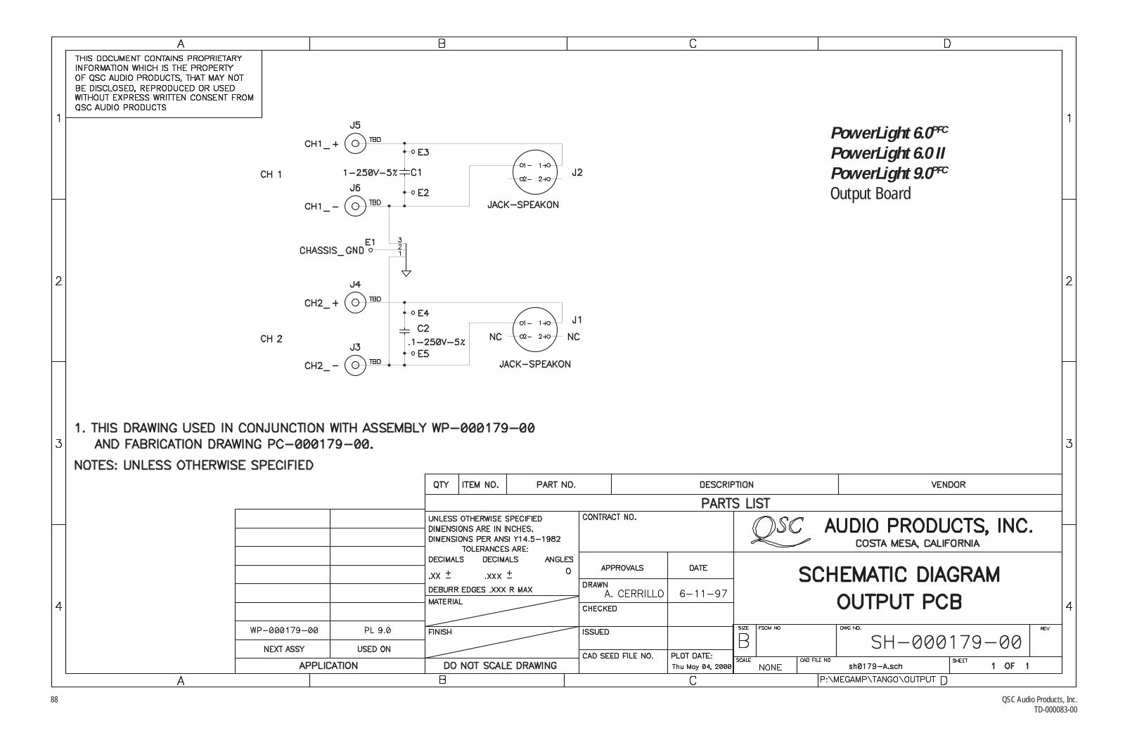
88 QSC Audio Products, Inc.TD-000083-00
PowerLight 6.0PFC
PowerLight 6.0 IIPowerLight 9.0PFC
Output Board

Technical Service Manual 89PowerLight 6.0 II, PowerLight 6.0PFC, and PowerLight 9.0PFC
2
1
2
1
DDRAIN
SSOURCE
CCONTROL
2
63
7
10
914
13
B4_N
B4_P
B3_N
B3_P
216
4
1
2
87
22
u-2
5V
C111
22
u-2
5V
C1
07
12
11
B2_P
B2_N
VN
B1_N
22u-25V
C62
VP
B1_P
+15V
84
84
84
84
84
84
VN
VP
84
C7
22
u-2
5V
C6
22
u-2
5V
PowerLight 6.0PFC
PowerLight 6.0 IIHousekeeping Supply(Audio Module)

90 QSC Audio Products, Inc.TD-000083-00
40 V
Node N182“B3_P” (through 150 resistor)Ω
p. 1C1
27 V
11 V
11 V
20 V
30 V
2
1
2
1
DDRAIN
SSOURCE
CCONTROL
2
63
7
10
914
13
B4_N
B4_P
B3_N
B3_P
216
4
1
2
87
22
u-2
5V
C111
22
u-2
5V
C1
07
12
11
B2_P
B2_N
VN
B1_N
22u-25V
C62
VP
B1_P
+15V
84
84
84
84
84
84
VN
VP
84
C7
22
u-2
5V
C6
22
u-2
5V
PowerLight 9.0PFC
Housekeeping Supply(Audio Module)

Technical Service Manual 91PowerLight 6.0 II, PowerLight 6.0PFC, and PowerLight 9.0PFC
PowerLight 6.0PFC
Power Supply Controller Board

92 QSC Audio Products, Inc.TD-000083-00
PowerLight 6.0PFC
Power Supply
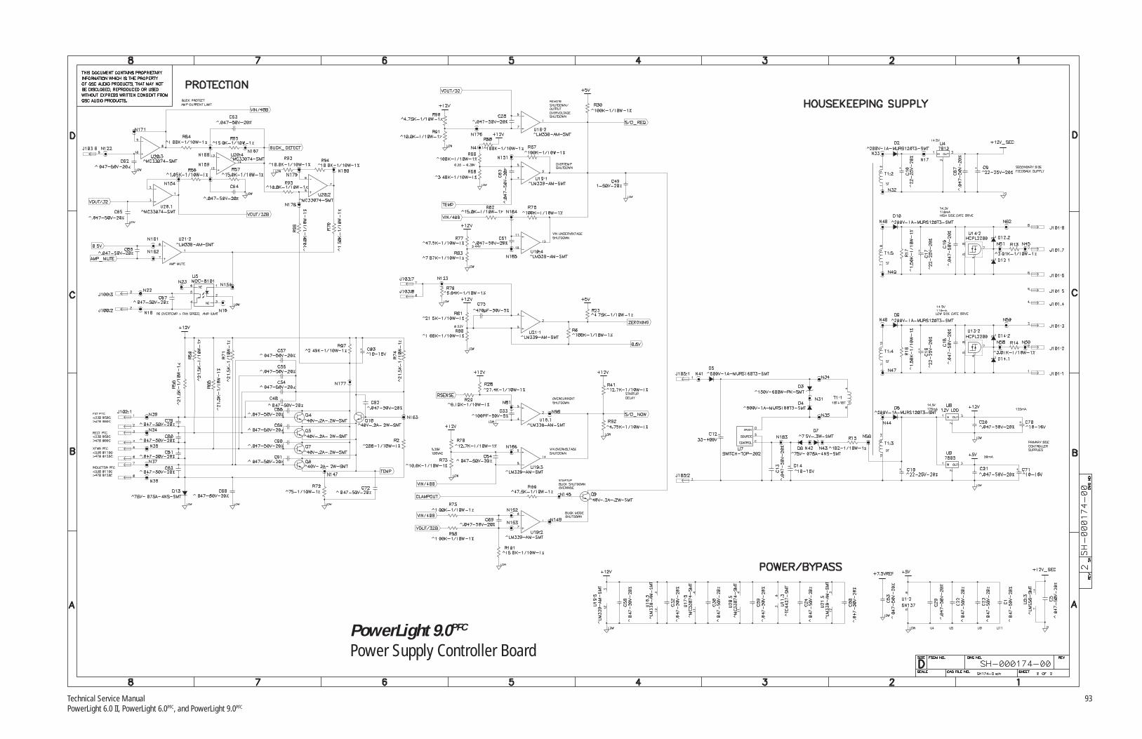
Technical Service Manual 93PowerLight 6.0 II, PowerLight 6.0PFC, and PowerLight 9.0PFC
PowerLight 9.0PFC
Power Supply Controller Board

94 QSC Audio Products, Inc.TD-000083-00
PowerLight 9.0PFC
Power Supply

Technical Service Manual 95PowerLight 6.0 II, PowerLight 6.0PFC, and PowerLight 9.0PFC
PRI_LO
V+17.2
RELAY/AMP_DRIVE
XFM_NTC+
XFM_NTC-
PFC_NTC+
PFC_NTC-
COR_NTC+
COR_NTC-
PRI_LO
V+17.2
PRI_LO
PRI_LO
SHUTDOWN_NOT
V+17.2
PRI_LO
PRI_LO
PRI_LO
RELAY/AMP_DRIVE NEUTRAL
PRI_LO
V+17.2
PRI_LO
HOT
PRI_HI
PRICAPCT
PRI_LO
PRI_LO
PRI_LO
V+17.2
PRI_LO
SWITCH_INHIBIT_DRIVE
SWITCHEDHV
V+17.2
V+17.2
PRI_LO
V+17.2
SYNCOUTB
OUTA
PRI_LO
PRI_LO
PRI_LOSOFTSTART
PRI_LO
PRI_LO
SW
ITC
H_IN
HIB
IT
PRI_LO
PRI_LO
100V
150V
200V
HVCOMMON
50V
PowerLight 6.0 IIPower Supply

96 QSC Audio Products, Inc.TD-000083-00
PRI_LO
cut board out,under body
V+5
PRI_LO
RELAY/AMP_DRIVE
V+5
3+
2-
1
PRI_LO
2.5v
Scale Factor1V = 150V
375v to 385VReg Range
5+
6-
7
PR
I_LO
V+5
PRI_LO
StopThreshold
PRI_LO
AC_LINE_LO
NEUTRAL
PRI_HI
HOT
AC_LINE
D15 >> D18
PUMP_POS
PRI_HI
2 WattsMax Dis.
PRICAPCT
PRI_HI
L1
V+5
V+5
2 WattsMax Dis.
PUMP_NEG
PRI_LO
PRI_LO
PUMP_NEG
PRI_HI
Hard Limitat 395V-400V
V+5
AC_LINE
26Kohm @ 60Hz
PUMP_NEG
V+17.2_FLOATINGV+17.2_FLOATING
PUMP_NEG
PRI_LO
V+5
PRI_LOPRICAPCT
pri PUMP_NEG
5v
12V(Unused)
15v
V+5
of
15vV+17.2
PRI_LO
PowerLight 6.0 IIPower Supply


“QSC” and the QSC logo are registered trademarks of QSC Audio Products, Inc. 1675 MacArthur Blvd. Costa Mesa, CA 92626 USAPHONE: +1 (714) 957-7150 TOLL-FREE IN USA: 1-800 772-2834 FAX: +1 (714) 754-6173
www.qscaudio.com