QP Series 2 Stage Compressors · Quincy Compressor QP Series compressors are heavy duty, air...
44
This manual contains important safety information and must be carefully read in its entirety and understood prior to installation by all personnel who install, operate and/or maintain this product. On-line product registration, parts ordering and warranty information is available at www.quincycompressor.com Manual No. 2022201802 July 2014 Edition QP Series 2 Stage Compressors Instruction Manual
Transcript of QP Series 2 Stage Compressors · Quincy Compressor QP Series compressors are heavy duty, air...

This manual contains important safety information and must be carefully read in its entirety and understood prior to installation by all personnel who install, operate and/or maintain this product.
On-line product registration, parts ordering and warranty information is available at www.quincycompressor.com
Manual No. 2022201802
July 2014 Edition
QP Series 2 Stage Compressors
Instruction Manual


QP Series Quincy Compressor
2022201802, July 2014 1 3501 Wismann Lane, Quincy Ill. - 62305-3116
ContentsSECTION 1 SAFETY Safety First ............................................................................................................................................................2Summary of Changes ............................................................................................................................................4
SECTION 2 SYSTEM DYNAMICSDescription & Application ....................................................................................................................................5Principles of Compression Cycles .........................................................................................................................5Principles of Lubrication Systems .......................................................................................................................5Principles of Cooling Systems ..............................................................................................................................5Principles of Dryers & Filters ..............................................................................................................................5
SECTION 3 INSTALLATIONReceiving Delivery ................................................................................................................................................7Freight Damage ....................................................................................................................................................7Location .................................................................................................................................................................8Electrical Supply Requirements...........................................................................................................................9Wiring & Piping Schematics ..............................................................................................................................10Mounting .............................................................................................................................................................17System Components ............................................................................................................................................17Induction System ................................................................................................................................................19Compressed Air Discharge System ....................................................................................................................20
SECTION 4 START-UP & OPERATIONPre-Starting Checklist ........................................................................................................................................24Initial Starting & Operating ..............................................................................................................................25Daily Starting Checklist .....................................................................................................................................26
SECTION 5 MAINTENANCE & LUBRICATIONStopping for Maintenance ..................................................................................................................................27Maintenance Schedule ........................................................................................................................................27Lubrication ..........................................................................................................................................................29Lubricant Filter ...................................................................................................................................................30Pulley / Sheave Alignment & Belt Tension ........................................................................................................30Pressure Switch Adjustment ..............................................................................................................................31Pilot Valve Adjustment Instructions ..................................................................................................................33
SECTION 6 TROUBLESHOOTINGTroubleshooting ..................................................................................................................................................34
SECTION 7 REFERENCE INFORMATIONDecal Locations ...................................................................................................................................................38

QP Series Quincy Compressor
2022201802, July 2014 2 3501 Wismann Lane, Quincy Ill. - 62305-3116
SECTION 1 SAFETY
Safety FirstAt Quincy Compressor safety is not only a primary concern, but a faithfully performed practice. Beginning with the design stage, safety is built into every Quincy compressor. It is the inten tion of this manual to pass along the “safety first” concept to you by providing safety precautions throughout its pages.
“DANGER !”, “WARNING !”, and “CAUTION !” are displayed in large bold capital letters in the left hand column to call attention to areas of vital concern. They represent different degrees of hazard seriousness, as stated below. The safety precaution is spelled out in bold upper and lower case letters in the right hand column.
Immediate hazards which will result in severe personal injury or death.
Hazards or unsafe practices that could result in personal injury or death.
Hazards or unsafe practices which could result in minor personal injury, product or property damage.
Each section of this instruction manual, as well as any instruc tions supplied by manufacturers of supporting equipment, should be read and understood prior to starting the compressor. If there are any questions regarding any part of the instructions, please call your local Quincy distributor, or the Quincy Compressor factory before creating a potentially hazardous situa tion. Life, limb, or equipment could be saved with a simple phone call.
Compressors are precision high speed mechanical equipment requiring caution in operation to minimize hazard to property and personnel. There are many obvious safety rules that must be ob served in the operation of this type of equipment. Listed below are some additional safety precautions that must be observed.
•Transfer of toxic, dangerous, flammable or explosive substances using Quincy Compressor products is at the user’s risk.
•All installation maintenance and repair must be performed by a qualified technician and/or electrician.
•Turn off and lockout/tagout (per OSHA regulation 1910.147) the main power disconnect switch before attempting to work or perform any maintenance.
•Do not attempt to service any part of the unit while it is operating.
•Per OSHA regulation 1910.147, relieve the system of all pressure before at-tempting to service any part of the unit.
•Allow ample time for the compressor to cool before performing service pro-
WARNING !
CAUTION !
DANGER !

QP Series Quincy Compressor
2022201802, July 2014 3 3501 Wismann Lane, Quincy Ill. - 62305-3116
cedures. Some surface temperatures exceed 350°F when the compressor is operating.
•Do not operate the unit with any of its safety guards, shields, screens, enclo-sure panels or doors removed.
•Do not remove or paint over any DANGER!, WARNING!, CAUTION!, or instructional materials attached to the compressor. Lack of information re-garding hazardous conditions can cause property damage or personal injury.
•Periodically check all pressure relief valves for proper operation.
•Do not change the pressure setting of the pressure relief valve, re strict the function of the pressure relief valve, or replace the pressure relief valve with a plug.
•Do not install a shutoff valve in the compressor discharge line with out first installing a pressure relief valve of proper size and design between the shutoff valve and the compressor.
•All components of the compressed air system must be properly rated for the application.
•Alterations must not be made to this compressor without Quincy Compres-sor’s approval.
•Be sure that all tools, shipping and installation debris have been re moved from the compressor and installation site prior to starting the compressor.
•Do not operate the compressor in excess of the ASME pressure vessel rating for the receiver or the service rating of the compressor, whichever is lower.
•Make a general overall inspection of the unit daily and correct any unsafe situations. All fasteners must be kept tight.
•Reckless behaviour of any kind involving compressed air is dangerous and can cause very serious injury to the participants.
•Wear safety glasses and hearing protection during operation, service and maintenance procedures.
•Provisions should be made to have the instruction manual readily available to the operator and maintenance personnel. If for any reason any part of the manual becomes illegible or the manual is lost, have it replaced immediately. The instruction manual should be read periodically to refresh one’s memory. It may prevent a seri ous or fatal accident.
•Never use a flammable or toxic solvent for cleaning the air filter or any parts.
Air used for breathing or food processing must meet OSHA 29 CFR 1910.134 or FDA 21 CFR 178.3570 regulations. Failure to do so may cause severe injury or death.DANGER !

QP Series Quincy Compressor
2022201802, July 2014 4 3501 Wismann Lane, Quincy Ill. - 62305-3116
Oil and moisture residue must be drained from the air receiver daily or after each use. Accumulations of oil residue in the receiver can be ignited by embers of carbon created by the heat of compres-sion, causing an explosion, damage to property and injury to per-sonnel.
When using battery cables to start engine driven units do not use more than a total of 40 ft. of #4 gauge cable (GND & HOT).
The owner, lessor or operator of any compressor unit manu factured by Quincy Compressor is hereby warned that failure to ob serve the safety precau-tions and procedures outlined in this manual may result in serious personal injury, damage to property, and may void your warranty. Quincy Compressor must authorize all warranty service. Before contacting your distributor or the factory, check the maintenance requirements and the troubleshooting guide for your compressor. Most warranty issues can be resolved by following proper maintenance procedures.
Quincy Compressor neither states as fact, nor in any way implies that the above list of safety precautions is an all inclusive list, the observance of which will prevent all damage to property or injury to personnel.
Every effort has been taken to ensure that complete and correct instructions have been included in this manual. However, possible product updates and changes may have occurred since this printing. Quincy Compressor reserves the right to change specifications with out incurring any obligation for equip-ment previously or subse quently sold.
Summary of Changes to This Manual(since previous printing dated January 2013):
· Clarified safety statement relative to properly rated components for the compressed air system.
· Updated lubricant capacity specifications as result of bearing carrier redesign.
· Added Lubricant Filter information.
WARNING !
CAUTION !
QP Series Quincy Compressor
2022201802, July 2014 5 3501 Wismann Lane, Quincy Ill. - 62305-3116
SECTION 2 SYSTEM DYNAMICS
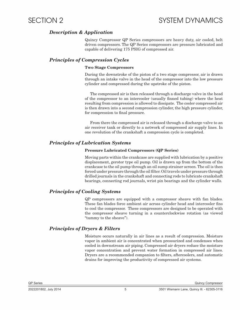
Description & ApplicationQuincy Compressor QP Series compressors are heavy duty, air cooled, belt driven compressors. The QP Series compressors are pressure lubricated and capable of delivering 175 PSIG of compressed air.
Principles of Compression Cycles Two Stage Compressors
During the downstroke of the piston of a two stage compressor, air is drawn through an intake valve in the head of the compressor into the low pressure cylinder and compressed during the upstroke of the piston.
The compressed air is then released through a discharge valve in the head of the compressor to an intercooler (usually finned tub ing) where the heat resulting from compression is allowed to dissipate. The cooler compressed air is then drawn into a second compression cylinder, the high pressure cylinder, for compression to final pressure.
From there the compressed air is released through a discharge valve to an air receiver tank or directly to a network of compressed air supply lines. In one revolution of the crankshaft a compression cycle is completed.
Principles of Lubrication SystemsPressure Lubricated Compressors (QP Series)
Moving parts within the crankcase are supplied with lubrication by a positive displacement, gerotor type oil pump. Oil is drawn up from the bottom of the crankcase to the oil pump through an oil sump strainer screen. The oil is then forced under pressure through the oil filter. Oil travels under pressure through drilled journals in the crankshaft and connecting rods to lubricate crankshaft bear ings, connecting rod journals, wrist pin bearings and the cylinder walls.
Principles of Cooling SystemsQP compressors are equipped with a compressor sheave with fan blades. These fan blades force ambient air across cylinder head and intercooler fins to cool the compressor. These compressors are designed to be operated with the compressor sheave turning in a counterclockwise rotation (as viewed “tummy to the sheave”).
Principles of Dryers & FiltersMoisture occurs naturally in air lines as a result of compression. Moisture vapor in ambient air is concentrated when pressurized and condenses when cooled in downstream air piping. Compressed air dryers reduce the moisture vapor concentration and prevent water formation in compressed air lines. Dryers are a recommended companion to filters, aftercoolers, and automatic drains for improving the productivity of compressed air systems.
QP Series Quincy Compressor
2022201802, July 2014 6 3501 Wismann Lane, Quincy Ill. - 62305-3116
Water and moisture vapor removal increases the efficiency of air operated equipment, reduces contamination and rusting, increases the service life of pneumatic equipment and tools, prevents air line freeze-ups, and reduces product rejects.
QP Series Quincy Compressor
2022201802, July 2014 7 3501 Wismann Lane, Quincy Ill. - 62305-3116
SECTION 3 INSTALLATION
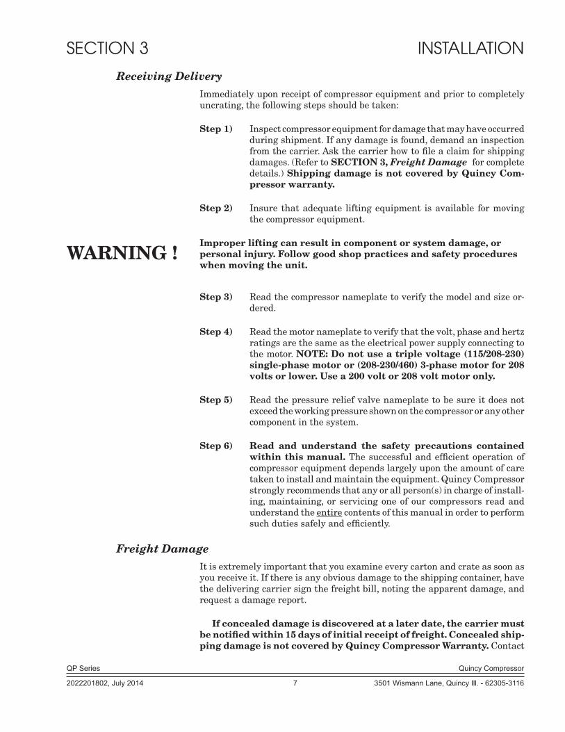
Receiving DeliveryImmediately upon receipt of compressor equipment and prior to completely uncrating, the following steps should be taken:
Step 1) Inspect compressor equipment for damage that may have occurred during shipment. If any damage is found, de mand an inspection from the carrier. Ask the carrier how to file a claim for shipping damages. (Refer to SECTION 3, Freight Damage for complete details.) Shipping damage is not covered by Quincy Com-pressor warranty.
Step 2) Insure that adequate lifting equipment is available for moving the compressor equipment.
Improper lifting can result in component or system damage, or personal injury. Follow good shop practices and safety procedures when moving the unit.
Step 3) Read the compressor nameplate to verify the model and size or-dered.
Step 4) Read the motor nameplate to verify that the volt, phase and hertz ratings are the same as the electrical power supply connecting to the motor. NOTE: Do not use a triple voltage (115/208-230) single-phase motor or (208-230/460) 3-phase motor for 208 volts or lower. Use a 200 volt or 208 volt motor only.
Step 5) Read the pressure relief valve nameplate to be sure it does not exceed the working pressure shown on the compressor or any other component in the system.
Step 6) Read and understand the safety precautions contained within this manual. The successful and efficient operation of compressor equipment depends largely upon the amount of care taken to install and maintain the equipment. Quincy Compressor strongly recommends that any or all person(s) in charge of install-ing, maintaining, or servic ing one of our compressors read and understand the entire contents of this manual in order to perform such duties safely and efficiently.
Freight DamageIt is extremely important that you examine every carton and crate as soon as you receive it. If there is any obvious damage to the shipping container, have the delivering carrier sign the freight bill, noting the apparent damage, and request a damage report.
If concealed damage is discovered at a later date, the carrier must be notified within 15 days of initial receipt of freight. Concealed ship-ping damage is not covered by Quincy Compressor Warranty. Contact
WARNING !
QP Series Quincy Compressor
2022201802, July 2014 8 3501 Wismann Lane, Quincy Ill. - 62305-3116
the carrier as soon as possible, giving them an opportunity to inspect the ship-ment at the premises where the delivery was made. Do not move the damaged freight from the premises where the original delivery was made. Retain all containers and packing for inspection by the carrier.
A claim form can be requested from the carrier: Standard Form for Pre-sentation of Loss and Damage Claims (form # 3208). Your claim will need to be substantiated with the following documents:
a.) form #3208
b.) original bill of lading
c.) original paid freight bill
d.) original invoice or certified copy
e.) other particulars obtainable in proof of loss or damage (photos, dam-age inspection, etc.)
The proper description and classification of our product in the National Motor Freight Classification 100-H, contained in item 118100, reads as fol-lows: Compressors, air, or air ends: with or without air tanks, hose or nozzles, mounted or not mounted.”
We suggest that these instructions be circulated to your shipping and receiving personnel.
LocationQP Series air compressors must be installed and operated in a secure, level, upright position in an area that is clean, dry, well lighted, adequately ventilated, and not less than 24 inches to a wall or other compressor. (Note: A gas engine will produce carbon monoxide; always provide adequate ventilation!) Inspec-tion and mainte nance checks are required daily. Therefore, sufficient space needs to be provided around the compressor for safe and proper in spection, cleaning, and maintenance.
Ample circu la tion of air must be provided across the compressor cylinders, heads and cooler (if so equipped). If at all possible, the pulley drive system (i.e. motor pul ley, compressor sheave, belts and guard) should face a wall to minimize any danger created by the drive system while the compressor is operating. Do not allow hot air from additional equipment to blow towards the compressor.
QP series compressors should be operated in temperatures under 104°F. In cold cli mates, the compressor should be installed in a heated building.
Do not operate this compressor in ambient temperatures lower than 0°F. A crankcase heater is recommended for a compressor that is to operate in temperatures under 32° F.
Under no circumstances should a compressor be used in an area that may be exposed to toxic, volatile, or corrosive atmo sphere. Do not store toxic, volatile, or corrosive agents near the compressor.
CAUTION !
WARNING !
QP Series Quincy Compressor
2022201802, July 2014 9 3501 Wismann Lane, Quincy Ill. - 62305-3116
Noise
Noise is a potential health hazard that must be considered. There are federal and local laws governing acceptable noise levels. Check with local officials for specifications.
Excessive noise can be effectively reduced through various meth ods. Total enclosures, intake silencers, baffle walls, relocating or iso lating the compressor can reduce noise levels. Care must be taken when constructing total enclosures or baffle walls. If not properly constructed or positioned, they could contribute to unacceptable noise levels or over heating. Consult your local Quincy distribu-tor if assis tance is required.
Unusual noise or vibration indicates a problem. Do not operate the compressor until the source has been identified and corrected.
Electrical Supply RequirementsThe electrical installation of this unit must be performed by a qualified electri-cian in accordance with the National Electrical Code (NEC) or the Canadian Electrical Code (CEC), the National Electrical Safety Code (NESC), OSHA and/or state and local codes. Failure to abide by the national, state and local codes may result in physical harm and/or property damage.
Before installation, the electrical supply must be checked for adequate wire size and transformer capacity. Verify that the electrical supply voltage matches the requirements of the motor. A suitable circuit breaker or fused disconnect switch should be provided. When a 3 phase motor is used to drive a compressor, any unreasonable voltage imbalance between the legs must be eliminated and any high or low voltage corrected to prevent excessive current draw. Note: This unit must be grounded.
High voltage may cause personal injury or death. Disconnect and lockout/tagout per OSHA regulation 1910.147 all electrical power supplies before opening the electrical enclosure or servic ing.
Never assume a compressor is safe to work on just because it is not operating. It could restart at any time. Follow all safety precau-tions outlined in SECTION 5, Stopping For Maintenance.
Electrical enclosures and components must be in compliance with NEMA environmental ratings for the areas in which they are being installed.
Overload Relay
An overload relay monitors the compressor motor electrical current and turns the compressor motor off when an overload is sensed. It is mounted on the bottom of the motor starter. The overload relay is designed for motors with a 1.15 service factor. The overload relay setting should be adjusted to the mo-tor nameplate amp rating. If the motor has a service factor rating other than 1.15, the overload relay setting must be adjusted to compensate. Contact your Quincy distributor for assistance.
WARNING !
DANGER !
WARNING !
WARNING !

QP Series Quincy Compressor
2022201802, July 2014 10 3501 Wismann Lane, Quincy Ill. - 62305-3116
Fig
. 3-1
3
Ph
ase
Mag
net
ic M
otor
Sta
rter
Wit
h A
uto
mat
ic S
tart
/ S
top
Con
trol
Wir
ing
Sch
emat
ic W
P17
44A
(R
ev. D
)
Mag
netic
Sta
rter
Con
tact
or
Ove
rload
Rel
ay
Con
nect
inco
min
g po
wer
line
s at
scr
ew te
rmin
als
L1, L
2 &
L3.
CA
UT
ION
!V
erif
y al
l wir
es a
re s
ecu
re
and
fast
ener
s ar
e to
rqu
ed
befo
re c
onn
ecti
ng
pow
er t
o th
e u
nit
.
All
wire
s ar
e re
d un
less
oth
erw
ise
spec
ified
.D
ashe
d lin
es re
pres
ent w
ires
supp
lied
by o
ther
s.A
t Ins
talla
tion,
the
cust
omer
is to
pro
vide
:D
isco
nnec
t and
bra
nch
circ
uit o
verc
urre
nt p
rote
ctio
n an
d gr
ound
ing
betw
een
the
pow
er s
uppl
y an
d th
e el
ectri
cal c
ontro
l enc
losu
re in
acc
or-
danc
e w
ith th
e N
atio
nal E
lect
rical
Cod
e (N
EC
), th
e C
anad
ian
Ele
ctric
al
Cod
e (C
EC
) and
/ or
any
loca
l cod
es h
avin
g pr
eced
ence
.

QP Series Quincy Compressor
2022201802, July 2014 11 3501 Wismann Lane, Quincy Ill. - 62305-3116
Fig
. 3-2
S
ingl
e P
has
e M
agn
etic
Mot
or S
tart
er W
ith
Au
tom
atic
Sta
rt /
Sto
p C
ontr
olW
irin
g S
chem
atic
WP
1744
B (
Rev
. D)
Mag
netic
Sta
rter
Con
tact
or
Ove
rload
Rel
ay
Con
nect
inco
min
g po
wer
line
s at
scr
ew te
rmin
als
L1 &
L2.
CA
UT
ION
!V
erif
y al
l wir
es a
re s
ecu
re
and
fast
ener
s ar
e to
rqu
ed
befo
re c
onn
ecti
ng
pow
er t
o th
e u
nit
.
All
wire
s ar
e re
d un
less
oth
erw
ise
spec
ified
.D
ashe
d lin
es re
pres
ent w
ires
supp
lied
by o
ther
s.A
t Ins
talla
tion,
the
cust
omer
is to
pro
vide
:D
isco
nnec
t and
bra
nch
circ
uit o
verc
urre
nt p
rote
ctio
n an
d gr
ound
ing
betw
een
the
pow
er s
uppl
y an
d th
e el
ectri
cal c
ontro
l enc
losu
re in
acc
or-
danc
e w
ith th
e N
atio
nal E
lect
rical
Cod
e (N
EC
), th
e C
anad
ian
Ele
ctric
al
Cod
e (C
EC
) and
/ or
any
loca
l cod
es h
avin
g pr
eced
ence
.

QP Series Quincy Compressor
2022201802, July 2014 12 3501 Wismann Lane, Quincy Ill. - 62305-3116
Fig
. 3-3
Sin
gle
Ph
ase
Com
bin
atio
n P
ress
ure
Sw
itch
/ O
verl
oad
Rel
ayW
ired
to
Mot
or
Con
nec
tion
Dia
gram
Con
nect
inco
min
g po
wer
line
s at
scr
ew te
rmin
als
L1 &
L2.
Pres
sure
Sw
itch
To R
emov
e th
e C
over
:1.
Tur
n th
e sw
itch
hand
le to
“OFF
” pos
ition
.2.
Rem
ove
smal
l scr
ews
on s
ide
of th
e co
ver.
3. P
ull t
he c
over
aw
ay fr
om th
e pr
essu
re s
witc
h.
To R
e-in
stal
l the
Cov
er:
1. M
ake
sure
the
switc
h ha
ndle
is in
the
“OFF
” po
sitio
n (a
s sh
own)
.2.
Car
eful
ly s
lide
the
cove
r ove
r the
pre
ssur
e sw
itch.
DO
NO
T FO
RC
E!3.
Re-
inst
all t
he s
mal
l cov
er s
crew
s an
d tig
hten
.
CA
UT
ION
!V
erif
y al
l wir
es a
re s
ecu
re
and
fast
ener
s ar
e to
rqu
ed
befo
re c
onn
ecti
ng
pow
er t
o th
e u
nit
.
At I
nsta
llatio
n, th
e cu
stom
er is
to p
rovi
de:
Bra
nch
circ
uit o
verc
urre
nt p
rote
ctio
n an
d gr
ound
ing
betw
een
the
pow
er s
uppl
y an
d th
e pr
essu
re s
witc
h in
acc
orda
nce
with
the
Nat
iona
l Ele
ctric
al C
ode
(NE
C),
the
Can
adia
n E
lect
rical
Cod
e (C
EC
) and
/ or
any
loca
l cod
es h
avin
g pr
eced
ence
.

QP Series Quincy Compressor
2022201802, July 2014 13 3501 Wismann Lane, Quincy Ill. - 62305-3116
Fig. 3-4Start / Stop Control
Piping Schematic WP1781B
QP Series Quincy Compressor
2022201802, July 2014 14 3501 Wismann Lane, Quincy Ill. - 62305-3116
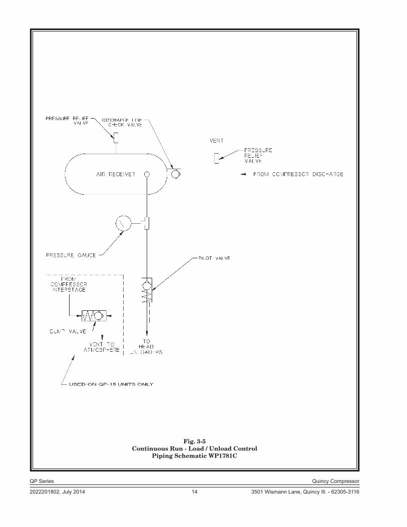
Fig. 3-5Continuous Run - Load / Unload Control
Piping Schematic WP1781C

QP Series Quincy Compressor
2022201802, July 2014 15 3501 Wismann Lane, Quincy Ill. - 62305-3116
Fig. 3-6Dual Control with Pilot Valve Unloading
Piping Schematic WP1781A

QP Series Quincy Compressor
2022201802, July 2014 16 3501 Wismann Lane, Quincy Ill. - 62305-3116
Fig. 3-7Dual Control with Solenoid Valve Unloading
Piping Schematic WP1781
QP Series Quincy Compressor
2022201802, July 2014 17 3501 Wismann Lane, Quincy Ill. - 62305-3116
Overload relays are designed to protect the motor from damage due to motor overload. If the overload relay trips persistently, DO NOT CONTINUE TO PUSH THE RESET BUTTON! Contact your lo-cal Quincy distributor for assistance.
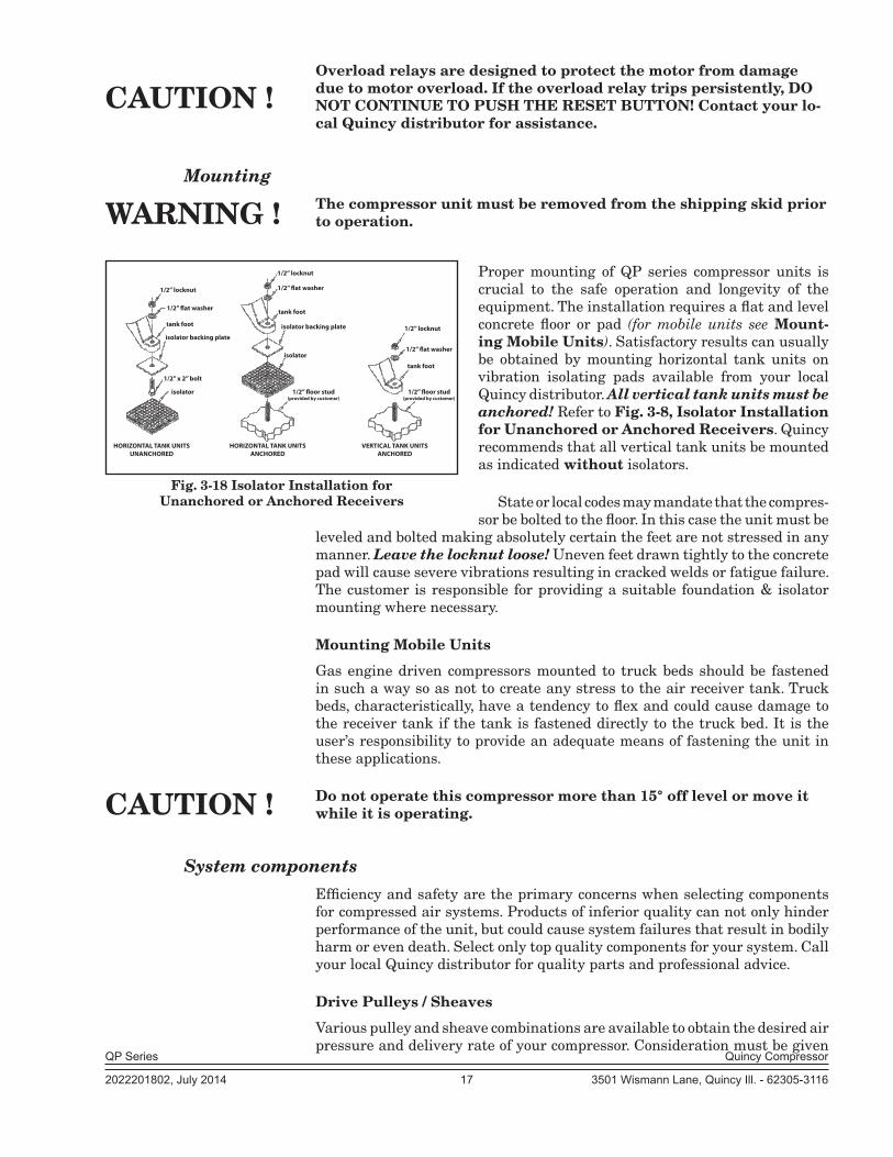
MountingThe compressor unit must be removed from the shipping skid prior to operation.
Proper mounting of QP series compressor units is crucial to the safe operation and longevity of the equipment. The installation requires a flat and level concrete floor or pad (for mobile units see Mount-ing Mobile Units). Satisfactory results can usually be obtained by mounting horizontal tank units on vibration isolating pads available from your local Quincy distributor. All vertical tank units must be anchored! Refer to Fig. 3-8, Isolator Installation for Unanchored or Anchored Receivers. Quincy recommends that all vertical tank units be mounted as indicated without isolators.
State or local codes may mandate that the compres-sor be bolted to the floor. In this case the unit must be
leveled and bolted making absolutely certain the feet are not stressed in any manner. Leave the locknut loose! Uneven feet drawn tightly to the concrete pad will cause severe vibrations resulting in cracked welds or fatigue failure. The customer is responsible for pro viding a suitable foundation & isolator mounting where necessary.
Mounting Mobile Units
Gas engine driven compressors mounted to truck beds should be fas tened in such a way so as not to create any stress to the air receiver tank. Truck beds, characteristically, have a tendency to flex and could cause damage to the receiver tank if the tank is fastened directly to the truck bed. It is the user’s responsibility to provide an adequate means of fas tening the unit in these applica tions.
Do not operate this compressor more than 15° off level or move it while it is operating.
System componentsEfficiency and safety are the primary concerns when selecting compo nents for compressed air systems. Products of inferior quality can not only hinder performance of the unit, but could cause system failures that result in bodily harm or even death. Select only top quality compo nents for your system. Call your local Quincy distributor for quality parts and professional advice.
Drive Pulleys / Sheaves
Various pulley and sheave combinations are available to obtain the de sired air pressure and delivery rate of your compressor. Consideration must be given
HORIZONTAL TANK UNITSANCHORED
VERTICAL TANK UNITSANCHORED
HORIZONTAL TANK UNITSUNANCHORED
1/2” locknut
1/2” �at washer
tank foot
isolator backing plate
1/2” x 2” bolt
isolator
1/2” locknut
1/2” �at washer
tank foot
isolator backing plate
isolator
1/2” �oor stud(provided by customer)
1/2” �oor stud(provided by customer)
tank foot
1/2” locknut
1/2” �at washer
Fig. 3-18 Isolator Installation for Unanchored or Anchored Receivers
CAUTION !
CAUTION !
WARNING !
QP Series Quincy Compressor
2022201802, July 2014 18 3501 Wismann Lane, Quincy Ill. - 62305-3116
to these combinations to ensure that the motor is not over loaded by operating above or below the designed speed range.
Whatever combination is employed, the drive pulleys & com pressor sheaves must be properly aligned and drive belt tension set to specifica tions (refer to SECTION 5, Pulley / Sheave Alignment & Belt Tension). Improper pul-ley/sheave alignment and belt ten sion can cause motor overloading, excessive vibration, and prema ture belt and/or bearing failure.
Excessive compressor RPM’s (speed) could cause a pulley or sheave to shatter. In an instant, the pulley or sheave could separate into fragments capable of penetrating the belt guard and causing bodily harm or death. Do not operate the compressor above the recom-mended RPM (refer to SECTION 2, Specifications).
Guards
All mechanical action or motion is hazardous in varying degrees and needs to be guarded. Guards should be designed to achieve the required degree of protection and still allow full air flow from the compressor sheave across the unit. Guards shall be in compliance with OSHA safety and health standards 29 CFR 1910.219 in OSHA manual 2206 and any state or local codes.
Guards must be fastened in place before starting the compressor and never removed before cutting off and locking out the main power supply.
Check Valves
Check valves are designed to prevent back-flow of air pressure in the com-pressed air system (air flows freely in one direction only). The check valve must be properly sized for air flow and tempera ture. Do not rely upon a check valve to isolate a compressor from a pressurized tank or compressed air delivery system during main tenance procedures!
Manual Shutoff Valves
Manual shutoff valves block the flow of air pressure in either direction. This type of valve can be used to isolate a compressor from a pressurized system, provided the system is equipped with a pressure relief valve ca pable of being manually released. The pressure relief valve must be installed between the manual shutoff valve and the compressor (refer to Fig. 3-9, Typical Drop Leg & Component Location).
Pressure Relief Valves
Pressure relief valves aid in preventing system failures by relieving system pressure when compressed air reaches a determined level. They are available in various pressure settings to accommodate a range of applications. Pressure relief valves are preset by the manufacturer and under no circumstances should the setting be changed by anyone other than the manufacturer.
Pressure relief valves are designed to protect compressed air systems in accordance with ASME B19 safety standards. Failure to provide properly sized pressure relief valves may cause property damage, severe personal injury or even death.
WARNING !
WARNING !
DANGER !

QP Series Quincy Compressor
2022201802, July 2014 19 3501 Wismann Lane, Quincy Ill. - 62305-3116
Pressure Switch
The pressure switch detects the demand for compressed air and allows the motor to start. When the demand is satisfied, the unit stops. Pressure switches provided by Quincy Compressor are pre-set at the factory and usually do not require adjustment.
Induction SystemAir Intake
A clean, cool and dry air supply is essential to the satisfactory operation of your QP Series air compressor. The standard air filter that the com pressor is equipped with when leaving the factory is of sufficient size and design to meet normal conditions, when properly serviced, in ac cordance with the maintenance section of this manual.
If, however, the compressor is to be installed in a location where consid-erable dust, dirt and other contaminants are prevalent, consult your local Quincy distributor for advice and optional filters. A condensate trap must be installed as close as possible to the inlet filter if, as a result of installation or environmental conditions, there is any risk of moisture forming in the inlet piping. It is the user’s responsibility to provide adequate filtration for those conditions. Oil bath filters are not to be used. Warranty will be void if a failure is determined to be caused by inadequate filtration.
Remote Inlet Filters
Depending on the size of the compressor and the size and construction of the room in which the unit operates, the air inlet may have to be located outside of the room. If it is necessary to remotely install the air filter, make the inlet piping as short and direct as possible. Remotely in stalled air filters can lead to vibrations in the inlet piping. These vibra tions can be minimized by adding a pulsation dampener in the inlet piping between the remote inlet filter(s) and the compressor.
If the inlet is routed to outside atmosphere, the inlet piping should be equipped with a hooded air filter and designed to prevent condensate, water or snow from being injested into the compressor.
All inlet piping should be at least the same size (or larger) in di ame ter as the inlet connection to the compressor. For every 10 feet of inlet piping or every 90° bend, increase the inlet piping diameter by one pipe size. The inlet piping must be thoroughly clean inside. Remove all weld slag, rust or dirt. Galvanized pipe with threaded or flanged fittings is preferred.
Never locate the compressor air inlet system where toxic, volatile or corrosive vapors, air temperatures exceeding 100°F, water, or extremely dirty air could be ingested. These types of at mospheres could adversely affect the performance of the compres sor system.
Compressed Air Discharge SystemThe discharge piping should be of the same diameter as the compressor discharge connection, or sized so that the pressure drop at any point in the
CAUTION !

QP Series Quincy Compressor
2022201802, July 2014 20 3501 Wismann Lane, Quincy Ill. - 62305-3116
system does not exceed 10% of the air receiver pressure. Install aux iliary air receivers near heavy loads or at the far end of a long system. This will insure sufficient pressure if the use is intermittent, or sudden large demands are placed on the system.
Discharge piping should slope to a drop leg (refer to Fig. 3-19, Typical Drop Leg & Component Location) or moisture trap to pro vide a collection point where moisture can be easily removed. All service line outlets should be installed above the moisture traps to prevent moisture from entering the tool or device using the air. Manual shutoff valves, protected by pressure relief valves, should be installed at all service line outlets to eliminate leakage while the tools are not in use.
The discharge piping from the tank of a stationary unit must be equipped with a properly rated flexible connection. As with any piping, all parts of the discharge piping should fit so as not to create any stress between the piping and components.
Pneumatic Circuit Breakers or Velocity Fuses
The Occupational Safety and Health Act (OSHA), Section 1926.303, Paragraph 7, published in the Code of Federal Regulations 29 CFR 1920.1, revised July 1, 1982 states that all hoses exceeding 1/2” inside diameter shall have a safety device at the source of supply or branch line to reduce pressure in case of a hose failure”
These pneumatic safety devices are designed to prevent hoses from whip-ping which could result in a serious or fatal accident.
Fig. 3-9 Typical Drop Leg & Component Location

QP Series Quincy Compressor
2022201802, July 2014 21 3501 Wismann Lane, Quincy Ill. - 62305-3116
Never join pipes or fittings with lead-tin soldering or use plastic pipe. Welded or threaded steel pipes and cast iron fittings, designed for the pres sures and temperatures, are recommended.
Pressure Vessels
Air receiver tanks and other pressure containing vessels such as (but not limited to) pulsation bottles, heat exchangers, moisture separators and traps, must be in accordance with ASME Boiler and Pressure Vessel Code Section VIII and ANSI B19.3 safety stan dards. They must be equipped with a properly sized pressure relief valve, pressure gauge, tank drain, & manual shutoff valve (refer to Fig. 3-9, Typical Drop Leg & Component Location).
Follow ASME code for air reciever tanks and other pressure con-taining vessels. Pressure vessels must not be modified, welded, repaired, reworked or subjected to operating conditions outside the nameplate ratings. Such actions will negate code status, affect insurance status and may cause property damage, severe injury or even death. Always replace worn, cracked or damaged tanks.
A drain valve must be located in the bottom of the air receiver to allow for moisture drainage. An auto matic drain valve is recommended. Extend piping away from the unit and any personnel in the immediate area to provide safe and convenient removal of excess moisture.
If the air receiver is going to be subject to temperatures of 32°F or below, provisions must be made to guard against freezing of the pressure relief valves, check valves, pressure gauge, and moisture drain.
Condensation
Rust can form inside the crankcase and on internal com ponents as a result of condensation. A compressor must operate long enough during each run cycle to reach full operating temperature in order to reduce the risk of condensation.
Lubricant that appears milky on the dipstick may have mixed with condensate. Failure to replace contaminated lubricant will result in damage to the compressor and may void warranty.
Condensation can also form in the air tank of your com pressor. When this happens, a mixture of air and mois ture will be expelled through the service valve and into what ever is connected to the valve (e.g. air hoses, metal air lines, pneumatic tools, spray guns). An in-line filter or dryer, available from your local Quincy distributor, may be re quired to eliminate the moisture.
Condensation in the air tank can be kept to a mini mum by draining the tank on a daily basis. This also reduces the risk of rust developing and weak ening the tank.
WARNING !
CAUTION !
WARNING !
Pix 1224Fig. 3-10 Internal Drain Tube
QP Series Quincy Compressor
2022201802, July 2014 22 3501 Wismann Lane, Quincy Ill. - 62305-3116
Manual Tank Drain Valve Operation
The manual tank drain valve is located on the underside of the air tank. Some tanks use an internal drain tube (Refer to Fig. 3-10, Internal Drain Tube) to drain the moisture. Tank pressure is required to force moisture out of the tank through the drain tube. Safe removal of tank moisture from the air tank is dependent upon an internal tank pressure of no more than 30 PSIG. Higher internal tank pressures are dangerous and could cause serious injury!
Oil and moisture residue must be drained from the air receiver daily or after each use. Accumulations of oil residue in the receiver can be ignited by embers of carbon created by the heat of compres-sion, causing an explosion, damage to property and injury to per-sonnel.
Do not open a manual tank drain valve on any air tank containing more than 30 PSIG of air pressure!
Never attempt to relieve an air tank by removing a pipe plug or any other system component!
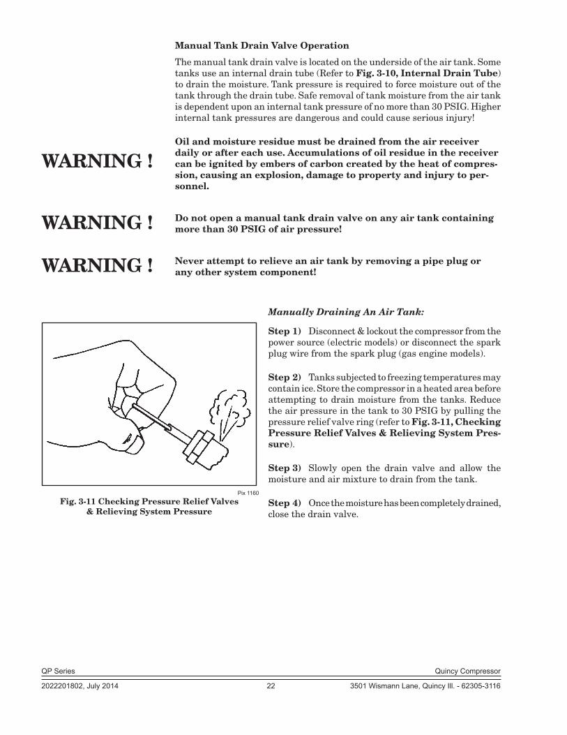
Manually Draining An Air Tank:
Step 1) Disconnect & lockout the compressor from the power source (electric models) or disconnect the spark plug wire from the spark plug (gas engine models).
Step 2) Tanks subjected to freezing temperatures may contain ice. Store the compressor in a heated area before attempting to drain moisture from the tanks. Reduce the air pressure in the tank to 30 PSIG by pulling the pressure relief valve ring (refer to Fig. 3-11, Checking Pressure Relief Valves & Relieving System Pres-sure).
Step 3) Slowly open the drain valve and allow the moisture and air mixture to drain from the tank.
Step 4) Once the moisture has been completely drained, close the drain valve.
Pix 1160
Fig. 3-11 Checking Pressure Relief Valves& Relieving System Pressure
WARNING !
WARNING !
WARNING !

QP Series Quincy Compressor
2022201802, July 2014 23 3501 Wismann Lane, Quincy Ill. - 62305-3116
Air Tank Inspection
Quincy Compressor recommends that all air tanks be inspected at scheduled inter-vals. Refer to Fig. 3-12 Recommended Air Tank Inspection Intervals for relative information. Measure tank wall thickness at several locations, including the lowest point where condensation can accumulate.
Refer to federal, state or provincial, or local codes for mandatory air tank maintenance information.
Tank Capacity
Horizontalor
Vertical
Minimum AllowableWall Thickness Visually
InspectHydrostatically
InspectHead Shell
30 Gal. Horizontal .094 .106 Yearly 10 Years30 Gal. Vertical .109 .111 Yearly 10 Years60 Gal. Horizontal .109 .135 Yearly 10 Years60 Gal. Vertical .109 .111 Yearly 10 Years80 Gal. Horizontal .109 .135 Yearly 10 Years80 Gal. Vertical .131 .133 Yearly 10 Years
120 Gal. Horizontal .131 .162 Yearly 10 Years120 Gal. Vertical .163 .199 Yearly 10 Years200 Gal. Horizontal .163 .199 Yearly 10 Years240 Gal. Horizontal .163 .199 Yearly 10 Years
Fig. 3-12 Recommended Air Tank Inspection Intervals
QP Series Quincy Compressor
2022201802, July 2014 24 3501 Wismann Lane, Quincy Ill. - 62305-3116
SECTION 4 START-UP & OPERATION
Pre-starting ChecklistNever assume a compressor is safe to work on just because it is not operating. It could restart at any time. Follow all safety precau-tions outlined in SECTION 5, Stopping For Maintenance.
Failure to perform the pre-starting checklist may result in me-chanical failure, property damage, serious injury or even death.
Steps 1 through 12 should be performed prior to connecting the unit to a power source. If any condition of the checklist is not satisfied, make the necessary adjustments or corrections before starting the compressor.
Step 1) Remove all installation tools from the compressor and check for installation debris.
Step 2) Unless otherwise specified, QP Series compressors are nor mally shipped with break-in lubri cant in the crankcase. Check the lubricant level in the crankcase. (Refer to SECTION 5, Lu-brication for quantity and types of lubri cant to be used.)
Step 3) Check motor pulley and compressor sheaves for alignment and tightness on shaft. (Refer to SECTION 5, Pulley / Sheave Align-ment & Belt Tension.)
Step 4) Manually rotate the compressor sheave several rotations to be sure there are no mechanical interferences.
Step 5) Check inlet piping installation (Refer to SECTION 3, Induction System.)
Step 6) Check belt tension. (Refer to SECTION 5, Pulley / Sheave Align-ment & Belt Tension.)
Step 7) Check all pressure connections for tightness.
Step 8) Make sure all pressure relief valves are correctly in stalled. (Refer to SECTION 3, System Components.)
Step 9) Be sure all guards are in place and securely mounted. (Refer to SECTION 3, System Components.)
Step 10) Check fuses, circuit breakers, and overload relays for proper size. Verify that the supply voltage matches the motor requirements. (Refer to SECTION 3, Electrical Supply Requirements.)
Step 11) Open all manual shutoff valves at and beyond the compres sor discharge.
WARNING !
WARNING !

QP Series Quincy Compressor
2022201802, July 2014 25 3501 Wismann Lane, Quincy Ill. - 62305-3116
Step 12) After all the above conditions have been satisfied, the unit can be connected to the proper power source.
Step 13) Jog the starter switch to check the rotational direction of the compressor. It should agree with the rotation arrow em bossed on the compressor sheave.
Step 14) Check for proper rotation of the cylinder cooling fan (fins inside sheave). The fan should blow cooling air across the cylinder.
Initial Starting & OperatingThis instruction manual, as well as any instructions supplied by manufacturers of supporting equipment, should be read and un derstood prior to starting the compressor. If there are any questions regarding any part of the instructions, please call your local Quincy distributor, or the Quincy Compressor factory.
When using battery cables to start engine driven units do not use more than a total of 40 ft. of #4 gauge cable (GND & HOT).
With the pre-starting checklist completed and satisfied, start the com-pressor. Watch and listen for excessive vibration and strange noises. If either exist, stop the compressor. Refer to SECTION 6, Troubleshooting for help in determining the cause of such prob lems.
Oil pressure should be maintained at 18 to 20 PSIG after 20 minutes of run time. Normally the oil pressure does not need to be adjusted. But if it does, loosen the locknut on the adjustment screw located on the right side of the oil pump housing (see Fig. 4-1, Oil Pressure Adjustment). Increase the oil pressure by turning the adjustment screw clockwise; de-crease the oil pressure by turn ing the adjusting screw counterclockwise. After adjustment tighten the locknut.
Check the air receiver pressure gauge or system pressure gauge for proper readings. If inadequate or excessive air pressure conditions exist,
refer to Section 6 Troubleshooting.
Heat created during the initial startup of a new compressor will cause slight expansion of the head(s). This slight expansion crushes the head gasket ever so slightly and affects the torque value of the cylinder fasteners (capscrews). To ensure optimal performance, Quincy recommends that you initially oper-ate the compressor for at least one hour. Shut the compressor off and follow precautions outlined in SECTION 5, Stopping for Maintenance. Retorque the cylinder to head capscrews to the specifications outlined in the parts book corresponding to the Record of Change for your compressor after the compres-sor has cooled.
Observe compressor operation closely for the first hour of opera tion and then frequently for the next seven hours. After the first eight hours, monitor the compressor at least once every eight hours. If any abnormal conditions are witnessed, stop the compressor and correct the problem. After two days of operation check belt tension, lubricant level, and inspect the system for leaks.
Pix 1220
Fig. 4-1 Oil Pressure Adjustment
OIL PRESSURE ADJUSTMENT
SCREW
CAUTION !
QP Series Quincy Compressor
2022201802, July 2014 26 3501 Wismann Lane, Quincy Ill. - 62305-3116
Quincy Compressor recommends that a new or rebuilt reciprocating compres-sor should be run for a total of 100 hours at full discharge operating pressure to break-in the new piston rings. Until the rings are seated, the compressor will discharge higher than normal amounts of lubricant. In light of this fact, the lubricant level should be checked more frequently during the 100 hour break-in period.
Daily Starting ChecklistDo not proceed until the Pre-starting Checklist and Initial Starting & Operating sub-sections have been read and are thor oughly understood.
Step 1) Check lubricant level in crankcase.
Step 2) Drain liquid from the air receiver and moisture trap (if so equipped).
Step 3) Check all hoses and fittings for weak or worn conditions and re-place if necessary.
Step 4) Jog the starter button and check compressor rotation (refer to Steps 14 & 15 of Pre-Starting Checklist).
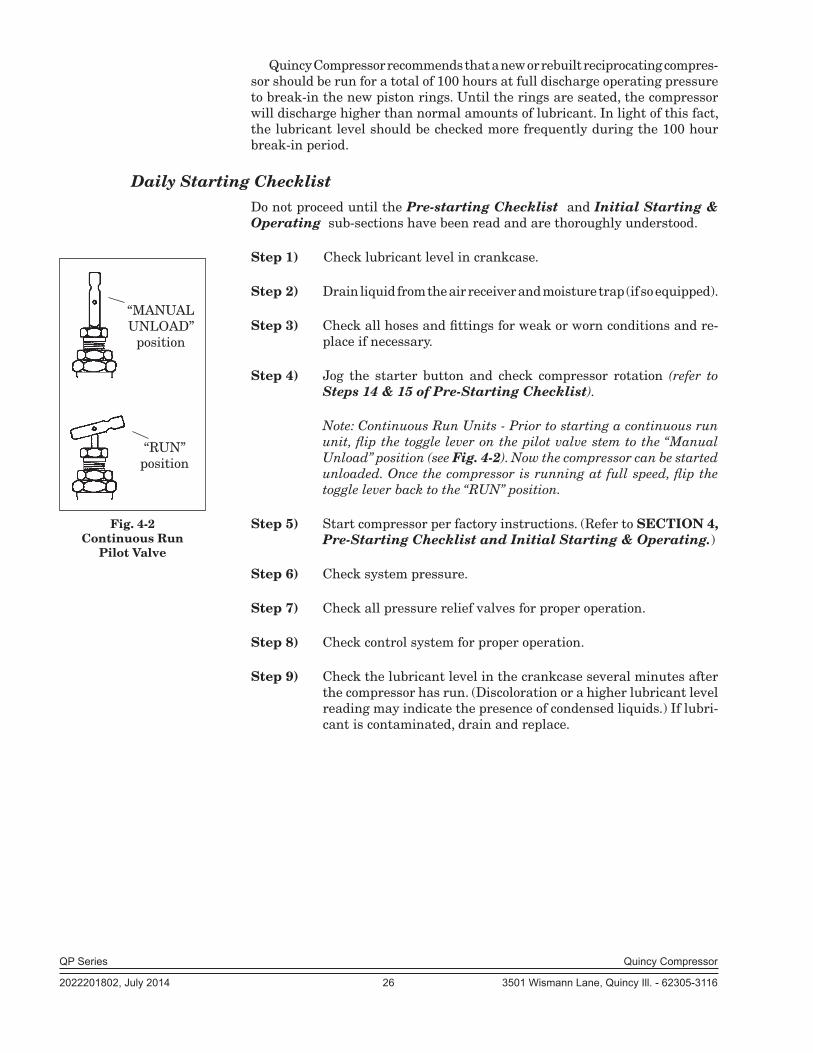
Note: Continuous Run Units - Prior to starting a continuous run unit, flip the toggle lever on the pilot valve stem to the “Manual Unload” position (see Fig. 4-2). Now the compressor can be started unloaded. Once the compressor is running at full speed, flip the toggle lever back to the “RUN” position.
Step 5) Start compressor per factory instructions. (Refer to SECTION 4, Pre-Starting Checklist and Initial Starting & Operating.)
Step 6) Check system pressure.
Step 7) Check all pressure relief valves for proper operation.
Step 8) Check control system for proper operation.
Step 9) Check the lubricant level in the crankcase several minutes after the compressor has run. (Discoloration or a higher lubricant level reading may indicate the presence of condensed liquids.) If lubri-cant is contaminated, drain and replace.
Fig. 4-2 Continuous Run
Pilot Valve
“MANUALUNLOAD”
position
“RUN”position
QP Series Quincy Compressor
2022201802, July 2014 27 3501 Wismann Lane, Quincy Ill. - 62305-3116
SECTION 5 MAINTENANCE & LUBRICATION
Stopping for MaintenanceThe following procedures should be followed when stopping the com pressor for maintenance or service:
Step 1) Per OSHA regulation 1910.147: The Control of Hazardous Energy Source (Lockout/Tagout), disconnect and lockout the main power source. Display a sign in clear view at the main power switch stat-ing that the compressor is being serviced.
Never assume a compressor is safe to work on just because it is not operating. It could restart at any time.
Step 2) Isolate the compressor from the compressed air supply by closing a manual shutoff valve upstream and downstream from the com-pressor. Display a sign in clear view at the shutoff valve stating that the compressor is being serviced.
Step 3) Open a pressure relief valve within the pressurized system to al-low it to be completely de-pressurized. NEVER remove a plug to relieve the pressure!
Step 4) Open all manual drain valves within the area to be serviced.
Step 5) Wait for the unit to cool before starting to service. (Temperatures of 125°F can burn skin. Some surface tem pera tures exceed 350°F when the compressor is operating.)
Maintenance ScheduleTo assure maximum performance and service life of your compres sor, a routine maintenance schedule should be developed. Refer to t he backof this manual for a maintenance procedures / intervals chart. Time frames may need to be shortened in harsher environments. Keep this instruction manual readily available near the compressor.
Every 8 Hours (or Daily)•QP-5, QP-7.5 and QP-10 lubricant levels should be kept at the top of the sight glass.
•Maintain lubricant levels of QP-15 models between high and low level marks on dipstick. Check the lubricant level several minutes after the compressor has run. (Discoloration or a higher lubricant level reading may indicate the presence of condensed liquids.) If lubricant is contaminated, drain and replace.
•Drain receiver tank, drop legs and traps in air distribution system. Receiver tanks subjected to freezing temperatures may contain ice. Store the compressor unit in a heated area before attempting to drain moisture from the tank.
•Give compressor an overall visual inspection and be sure safety guards are in place.
WARNING !
QP Series Quincy Compressor
2022201802, July 2014 28 3501 Wismann Lane, Quincy Ill. - 62305-3116
•Check for any unusual noise or vibration.•Check for lubricant leaks.•Check all pressurized components for rust, cracks or leaks. Immediately discontinue use of the equipment and relieve all system pressure if any of these problems are discovered. Do not use the equipment until it has been inspected and repaired by a qualified mechanic.
Every 40 Hours (or Weekly)•Manually operate the pressure relief valves to be certain they are working.
•Clean the cooling surfaces of the intercooler, aftercooler and compressor.•Check the compressor for air leaks. •Check the compressed air distribution system for leaks.•Inspect lubricant for contamination & change if necessary. •Clean or replace the air intake filter. Check more often under humid or dirty conditions.
After Initial 100 Hours•Completely drain the crankcase of break-in lubricant and replace with Quin-Cip-D or Quinc-Cip and new oil filter
Every 160 Hours (or Monthly)•Check belt tension
Every 500 Hours (or Every 3 Months)•When Quin-Cip lubricant is used, change lubricant every 500 hours or every 3 months, whichever occurs first (change more frequently in harsher environments).
•Torque pulley clamp screws or jamnut.
Every 1000 Hours (or Every 6 Months)•When Quin-Cip-D lubricant is used, lubricant change intervals may be extended to every 1000 hours or every 6 months, whichever occurs first (change more frequently in harsher conditions).
•Retorque the cylinder to head capscrews (Refer to SECTION 4, Torquing Cylinder to Head Capscrews).
•Inspect compressor valves for leakage and/or carbon build-up. If exces-sive sludge build-up exists inside the crankcase, clean the inside of the crankcase as well as the screen. Never use a flammable or toxic solvent for cleaning. Always use a safety solvent and follow the directions provided.
Every 2000 Hours (or Every 12 Months)•Inspect the pressure switch diaphragm and contacts. Inspect the contact points in the motor / starter.
Servicing Reed Valves
QP Series compressor valve plates and reed valves should be inspected and cleaned on a regular basis. The reed valves are made of stainless steel and can be cleaned with a stiff bristle brush(not a wire brush!). A clean safety solvent may also be used to loosen carbon deposits on the valve plates and reed valves. Handle all parts with care; do not bend, mar or scratch any sealing surfaces.
Never use gasoline, thinners, or other flammable solutions to clean valves or related parts.DANGER !

QP Series Quincy Compressor
2022201802, July 2014 29 3501 Wismann Lane, Quincy Ill. - 62305-3116
LubricationQP Series basic compressors and units are normally shipped from the factory with break-in lubricant in the crankcase. Before starting your compressor, check the lubricant level in the crankcase. The lubricant level of QT-5, QP-5, QP-7.5 and QP-10 compressors must be kept at the top of the sightglass. The lubricant level of QP-15 compressors must register be-tween the high and low marks on the dipstick. Replace the break-in lubricant after 100 hours of operation. In order to qualify for the Ster-ling Blue 7 year Warranty, Quin-Cip-D must be used in the QP Pro and Max packages. The Sterling Blue 100 Hour Kit is shipped with QP Pro and Max packages.
Quin-Cip and Quin-Cip-D lubricants have proven under extensive testing to min imize friction and wear, limit lubricant carryover, and reduce carbon and varnish deposits. They will support the performance characteristics and life designed into all Quincy compressors and are highly rec ommended. Refer to the charts below to determine the correct amount of lubricant and viscosity to use for your model and applica tion.
Approximate Crankcase Lubricant Capacities
Basic Compressor Model Lubricant Capacity
QP-5 & QP-7.5 1 qt. & 26 oz. (1.72 lit.) QP-10 2 qts. & 22 oz. (2.54 lit.) QP-15 3 qts. & 30 oz. (3.73 lit.)
Lubricant Specifications Quin-Cip
Ambient Temperature SAE Viscosity ISO Viscosity
0-32° F SAE 10W ISO 32 32-80°F SAE 20W ISO 68 60-104°F SAE 30 ISO 100
Quin-Cip-D
Ambient Temperature SAE Viscosity ISO Viscosity
15-104°F SAE 30 ISO 100
The lubricant selected must have a pour point at least15°F lower than the minimum expected ambient temperature . CAUTION !
Avg. # of Hrs. Compressor
Operates Daily
# of Days of Operaton to Reach:
50 Hrs. 100 Hrs.4 13 days 25 days6 9 days 17 days8 6 days 13 days
10 5 days 10 days
QP Series Quincy Compressor
2022201802, July 2014 30 3501 Wismann Lane, Quincy Ill. - 62305-3116
Lubricant FilterWhen replacing the filter, apply a thin film of lubricant to the gasket surface of the new filter prior to installing it onto the pump housing. Spin the filter on the threaded stud until the gasket makes contact with the housing. Then tighten the filter an additional 3/4 turn.
The filter provided with the compressor is for use with Quin-Cip or Qui-Cip-D lubricant only.
A bent or damaged filter may rupture and leak. Do not use a filter in this condition.
Pulley / Sheave Alignment & Belt TensionImproper pulley/sheave alignment and belt tension are causes for mo tor overloading, excessive vibration, and premature belt and/or bearing failure. To prevent this from happening, check the pulley/sheave alignment and belt tension on a regular basis (refer to SECTION 5, Maintenance Schedule).
Periodically inspect the motor pulley(s) and compressor sheave(s) for oil, grease, nicks or burrs. Clean or replace if necessary. Make sure they are securely fastened. Align the compressor sheave with the motor or engine pulley. Drive belt grooves of the pulley(s) and sheave(s) should be in line with each other. The compressor crankshaft must be parallel to the motor or engine drive shaft.
Belt tension should be measured and adjusted to provide smooth op eration. Step-by-step procedures are provided here to correctly measure and set the drive belt tension:
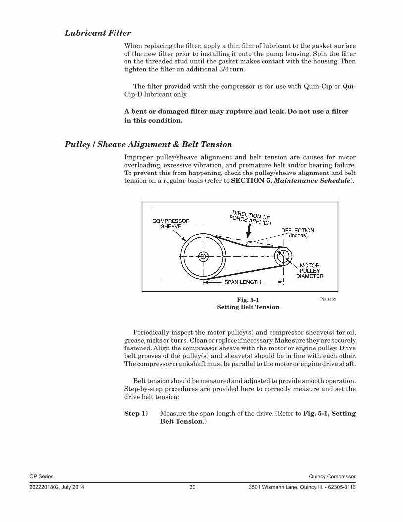
Step 1) Measure the span length of the drive. (Refer to Fig. 5-1, Setting Belt Tension.)
Pix 1152Fig. 5-1 Setting Belt Tension

QP Series Quincy Compressor
2022201802, July 2014 31 3501 Wismann Lane, Quincy Ill. - 62305-3116
Belt Motor Pulley Recommended Cross Dia. Range Deflection Force (lbs.) Section (inches) Minimum Maximum
B 4.6 4.0 5.9 B 5.0 - 5.4 4.5 6.7 B 5.6 - 6.4 5.0 7.4 B 6.8 - 9.4 5.8 8.6
Step 2) Determine the amount of deflection ( in inches) required to mea-sure de flection force (in pounds) by multi plying the span length x 1/64 (.016) (i.e. 32” span length x 1/64 [.016] = 1/2”[.50] of deflection required to measure de flection force).
Step 3) Lay a straightedge across the top outer surface of a drive belt from pulley to sheave.
Step 4) At the center of the span, perpendicu-lar to the belt, apply pressure to the outer surface of the belt with a belt tension gauge (refer to Fig. 5-2, Belt Tension Gauge). Force the belt to the predetermined deflection (refer to Step 2 above). Record the reading on the belt tension gauge and compare to the chart following Fig 5-1. The de-flection force reading should be within the mini-mum and maximum values shown. Adjust belt(s) accord ingly. New belts should be initially tensioned to the maximum value plus 33% (multiply by 1.33).
Step 5) Recheck the tension of the new belts several times in the first 50 hours of operation and adjust if necessary. Thereafter, check belt tension on a regular basis (refer to SECTION 5, Mainte-nance Schedule).
Pressure Switch AdjustmentPressure switches provided by Quincy Compressor are pre-set at the factory and usu ally do not require adjustment. However, the following procedures can be performed by a qualified electrician to adjust the pressure switch.
Step 1) Remove the pressure switch cover.
Step 2) While the compressor is running, screw the spring loaded adjustment screw in (clockwise) to increase the amount of air pressure required to open the switch and stop the unit. Screw the spring loaded adjustment screw out (counterclockwise) to decrease the amount of air pressure required to open the switch and stop the unit.
Pix 1067
Fig. 5-3 Pressure Switch
PRESSURE ADJUSTMENT
SCREW
ELECTRICAL CONTACTS
Fig. 5-2 Belt Tension GaugePix 1153
POCKET CLIP
SLIDING RUBBER O-RINGS
DEFLECTION FORCE SCALE(READ DOWN)
DEFLECTION DISTANCE
SCALE(READ UP)

QP Series Quincy Compressor
2022201802, July 2014 32 3501 Wismann Lane, Quincy Ill. - 62305-3116
Electric power always exists inside the pressure switch whenever the compressor package is connected to a power supply. Be care-ful not to touch any electrical leads when adjusting the pres sure switch.
Never exceed the designed pressure for the system or overload the motor beyond its Maximum Amp Draw.
* Full Load Amps x Service Factor = Maximum Amp Draw
Never assume a compressor is safe to work on just because it is not operating. It may be in the automatic stand-by mode and may re-start any time. Follow all safety precautions outlined in SECTION 5, Stopping For Maintenance.
WARNING !
* Full load amps (FLA) & Service Factor can be found on the motor nameplate.
WARNING !
WARNING !
QP Series Quincy Compressor
2022201802, July 2014 33 3501 Wismann Lane, Quincy Ill. - 62305-3116
PILOT VALVE ADJUSTMENTS
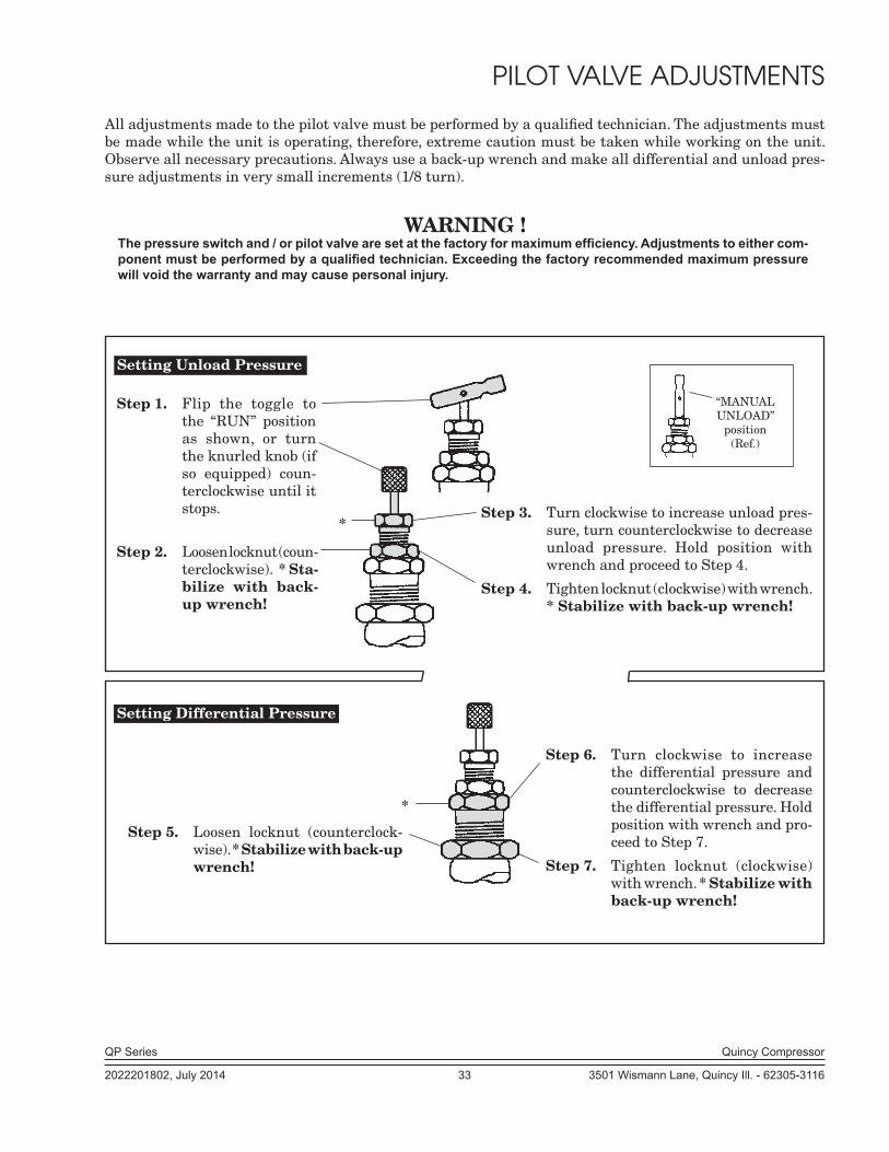
All adjustments made to the pilot valve must be performed by a qualified technician. The adjustments must be made while the unit is operating, therefore, extreme caution must be taken while working on the unit. Observe all necessary precautions. Always use a back-up wrench and make all differential and unload pres-sure adjustments in very small increments (1/8 turn).
WARNING !The pressure switch and / or pilot valve are set at the factory for maximum efficiency. Adjustments to either com-ponent must be performed by a qualified technician. Exceeding the factory recommended maximum pressure will void the warranty and may cause personal injury.
*
Setting Unload Pressure
*
Step 1. Flip the toggle to the “RUN” position as shown, or turn the knurled knob (if so equipped) coun-terclockwise until it stops.
Step 2. Loosen locknut (coun-terclockwise). * Sta-bilize with back-up wrench!
Step 3. Turn clockwise to increase unload pres-sure, turn counterclockwise to decrease unload pressure. Hold position with wrench and proceed to Step 4.
Step 4. Tighten locknut (clockwise) with wrench. * Stabilize with back-up wrench!
Setting Differential Pressure
Step 5. Loosen locknut (counterclock-wise). * Stabilize with back-up wrench!
Step 6. Turn clockwise to increase the differential pressure and counterclockwise to decrease the differential pressure. Hold position with wrench and pro-ceed to Step 7.
Step 7. Tighten locknut (clockwise) with wrench. * Stabilize with back-up wrench!
“MANUALUNLOAD”
position(Ref.)

QP Series Quincy Compressor
2022201802, July 2014 34 3501 Wismann Lane, Quincy Ill. - 62305-3116
SECTION 6 TROUBLESHOOTING
Trouble Probable Cause
Low discharge pressure •Restricted inlet •Defective compressor valves or valve unloading mechanism •Leaks in the compressed air distribution system at fittings, connections, etc. •Unloader pilot valve defective or set wrong •Pressure switch defective or set wrong •Drive belt slipping •Incorrect speed •Worn piston rings or loose piston •Leaking head gasket •Drain valve open •Defective pressure gauge •Pressure relief valve leaking •Clogged intercooler •Compressor incorrectly sized for the alti tude it is operating at •Piston rings not seated; allow 100 hours at full pressure
Water in the crankcase •Compressor does not run long enough to get hot and vaporize the liquids (lubricant appears milky) squeezed out of the air during compression (compressor may be too large for application) •Incorrect or inferior grade of lubricant •System pressure leaking back through dis charge valve
Rusty valves •Compressor operated too infrequentlyand/or cylin ders •Compressor does not run long enough to get hot and vaporize the liquids squeezed out of the air during compression (compressor may be too large for application) •Compressor not properly prepared for stor age •Discharge line from compressor head is pointed upward allowing con densation to drain back at shutdown
Excessive vibration •Incorrect speed •Compressor valves not functioning prop erly •Loose pulley/sheave •Compressor, motor or engine not secured tightly, or tightened into a bind •Foundation or frame inadequate •Piping inadequately supported or tightened into a bind •Excessive discharge pressure •Compressor feet may need to be leveled with shims

QP Series Quincy Compressor
2022201802, July 2014 35 3501 Wismann Lane, Quincy Ill. - 62305-3116
Trouble Probable Cause
Excessive drive belt wear •Pulley/sheave out of alignment •Belt too loose or too tight •Belt slipping •Pulley/sheave wobbling •Pulley/sheave groove damaged or rough •Incorrect belts Low oil pressure •Oil sump strainer plugged •Excessive leakage at crankshaft seals •Low oil level •Oil pump incorrectly assembled to the bear ing carrier (“o”ring not properly located between oil pump body & bearing carrier) •Oil pressure adjusting screw not set properly •Defective oil pressure gauge
Compressor loads •Air receiver too smalland unloads excessively •Compressor valves or unloaders defective •Excessive system leakage •Compressor operating at incorrect speed •Unloader pilot differential set too close •Pressure switch defective
Defective pressure switch •Moisture &/or oil buildup on the pressure switch diaphragm •Ruptured diaphragm •Burned contact points •Plugged air passage from the receiver to the pressure switch •Loose electrical connection Excessive air pressure •Air pressure gauge inaccuratein air receiver •Leaks in unloader piping system •Defective compressor head unloader •Pilot valve or pressure switch set incor rectly or defective •Pressure switch wired incorrectly •Tube to compressor head unloader plugged Excessive •Intercooler restricted or pluggedintercooler pressure •Compressor valves in second stage broken or not functioning properly •Pilot valve or pressure switch set incor rectly or defective
QP Series Quincy Compressor
2022201802, July 2014 36 3501 Wismann Lane, Quincy Ill. - 62305-3116
Trouble Probable Cause
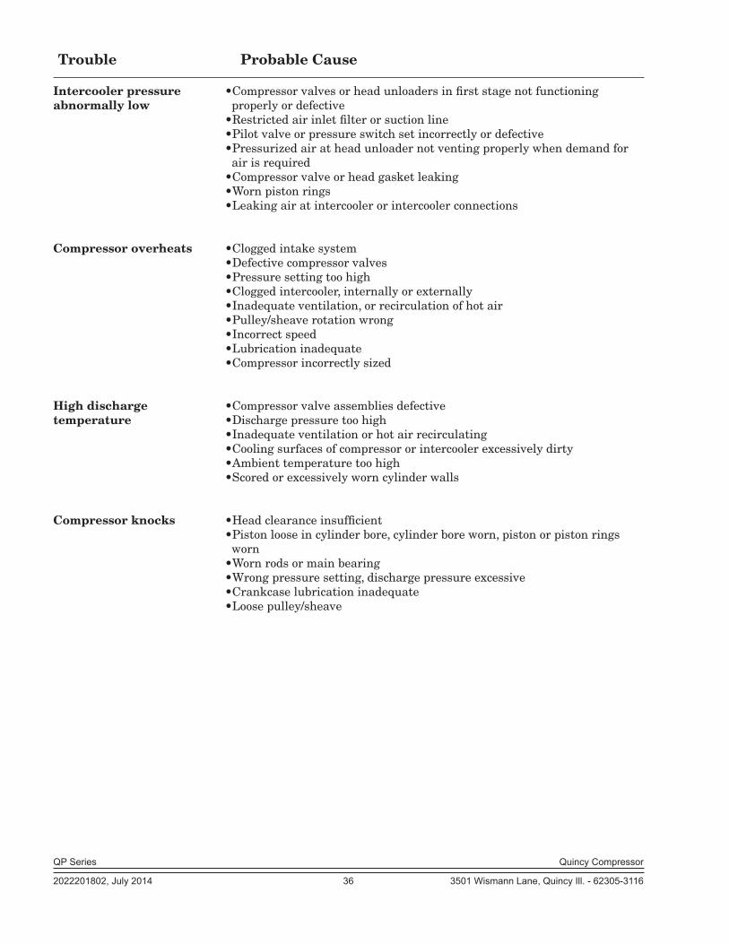
Intercooler pressure •Compressor valves or head unloaders in first stage not functioning abnormally low properly or defective •Restricted air inlet filter or suction line •Pilot valve or pressure switch set incor rectly or defective •Pressurized air at head unloader not vent ing properly when demand for air is re quired •Compressor valve or head gasket leaking •Worn piston rings •Leaking air at intercooler or intercooler connections
Compressor overheats •Clogged intake system •Defective compressor valves •Pressure setting too high •Clogged intercooler, internally or exter nally •Inadequate ventilation, or recirculation of hot air •Pulley/sheave rotation wrong •Incorrect speed •Lubrication inadequate •Compressor incorrectly sized
High discharge •Compressor valve assemblies defectivetemperature •Discharge pressure too high •Inadequate ventilation or hot air recirculat ing •Cooling surfaces of compressor or inter cooler excessively dirty •Ambient temperature too high •Scored or excessively worn cylinder walls Compressor knocks •Head clearance insufficient •Piston loose in cylinder bore, cylinder bore worn, piston or piston rings worn •Worn rods or main bearing •Wrong pressure setting, discharge pressure excessive •Crankcase lubrication inadequate •Loose pulley/sheave
QP Series Quincy Compressor
2022201802, July 2014 37 3501 Wismann Lane, Quincy Ill. - 62305-3116
Trouble Probable Cause
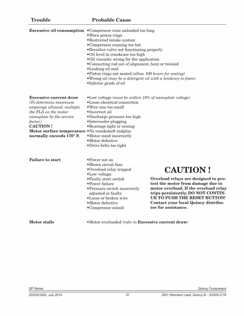
Excessive oil consumption •Compressor runs unloaded too long •Worn piston rings •Restricted intake system •Compressor running too hot •Breather valve not functioning properly •Oil level in crankcase too high •Oil viscosity wrong for the application •Connecting rod out of alignment, bent or twisted •Leaking oil seal •Piston rings not seated (allow 100 hours for seating) •Wrong oil (may be a detergent oil with a tendency to foam) •Inferior grade of oil
Excessive current draw •Low voltage (must be within 10% of name plate voltage) (To determine maximum •Loose electrical connectionamper age allowed, multiply •Wire size too smallthe FLA on the motor •Incorrect oilnameplate by the service •Discharge pressure too highfactor.) •Intercooler pluggingCAUTION ! •Bearings tight or seizingMotor surface temperature •No crankshaft endplaynormally exceeds 170° F. •Motor sized incorrectly •Motor defective •Drive belts too tight
Failure to start •Power not on •Blown circuit fuse •Overload relay tripped •Low voltage •Faulty start switch •Power failure •Pressure switch incorrectly adjusted or faulty •Loose or broken wire •Motor defective •Compressor seized
Motor stalls •Motor overloaded (refer to Excessive current draw)
Overload relays are designed to pro-tect the motor from damage due to motor overload. If the overload relay trips persistently, DO NOT CONTIN-UE TO PUSH THE RESET BUTTON! Contact your local Quincy distribu-tor for assistance.
CAUTION !
QP Series Quincy Compressor
2022201802, July 2014 38 3501 Wismann Lane, Quincy Ill. - 62305-3116
SECTION 7 REFERENCE INFORMATION
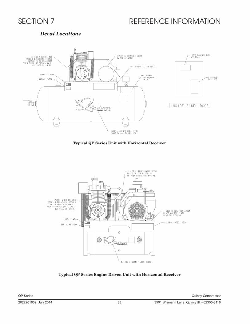
Decal Locations
Typical QP Series Unit with Horizontal Receiver
Typical QP Series Engine Driven Unit with Horizontal Receiver

QP Series Quincy Compressor
2022201802, July 2014 39 3501 Wismann Lane, Quincy Ill. - 62305-3116
Typical QP Series Unit with Vertical Receiver
QP Series Quincy Compressor
2022201802, July 2014 40 3501 Wismann Lane, Quincy Ill. - 62305-3116
QUINCY COMPRESSORSTANDARD TERMS AND CONDITIONS
LEGAL EFFECT: Except as expressly otherwise agreed to in writing by an authorized representative of Seller, the following terms and conditions shall apply to and form a part of this order and any additional and/or different terms of Buyer’s purchase order or other form of acceptance are rejected in advance and shall not become a part of this order.
The rights of Buyer hereunder shall be neither assignable nor transferable except with the written consent of Seller.
This order may not be canceled or altered except with the written consent of Seller and upon terms which will indemnify Seller against all loss oc-casioned thereby. All additional costs incurred by Seller due to changes in design or specifications, modification of this order or revision of product must be paid for by Buyer.
In addition to the rights and remedies conferred upon Seller by this order, Seller shall have all rights and remedies conferred at law and in equity and shall not be required to proceed with the performance of this order if Buyer is in default in the performance of such order or of any other contract or order with seller.
TERMS OF PAYMENT: Unless otherwise specified in the order acknowl-edgment, the terms of payment shall be 1% 15, net forty-five (45) days after shipment. These terms shall apply to partial as well as complete shipments. If any proceeding be initiated by or against Buyer under any bankruptcy or insolvency law, or in the judgment of Seller the financial condition of Buyer, at the time the equipment is ready for shipment, does not justify the terms of payment specified, Seller reserves the right to require full payment in cash prior to making shipment. If such payment is not received within fifteen (15) days after notification of readiness for shipment, Seller may cancel the order as to any unshipped item and require payment of its reasonable cancellation charges.
If Buyer delays shipment, payments based on date of shipment shall become due as of the date when ready for shipment. If Buyer delays completion of manufacture, Seller may elect to require payment according to percentage of completion. Equipment held for Buyer shall be at Buyer’s risk and storage charges may be applied at the discretion of Seller.
Accounts past due shall bare interest at the highest rate lawful to contract for but if there is no limit set by law, such interest shall be eighteen percent (18%). Buyer shall pay all cost and expenses, including reasonable attorney’s fees, incurred in collecting the same, and no claim, except claims within Seller’s warranty of material or workmanship, as stated below, will be recognized unless delivered in writing to Seller within thirty (30) days after date of shipment.
TAXES: All prices exclude present and future sales, use, occupation, license, excise, and other taxes in respect of manufacture, sales or delivery, all of which shall be paid by Buyer unless included in the purchase price at the proper rate or a proper exemption certificate is furnished.
ACCEPTANCE: All offers to purchase, quotations and contracts of sales are subject to final acceptance by an authorized representative at Seller’s plant.
DELIVERY: Except as otherwise specified in this quotation, delivery will be F. O. B. point of shipment. In the absence of exact shipping instruction, Seller will use its discretion regarding best means of insured shipment. No liability will be accepted by Seller for so doing. All transportation charges are at Buyer’s expense. Time of delivery is an estimate only and is based upon the receipt of all information and necessary approvals. The shipping schedule shall not be construed to limit seller in making commitments for materials or in fabricating articles under this order in accordance with Seller’s normal and reasonable production schedules.
Seller shall in no event be liable for delays caused by fires, acts of God, strikes, labor difficulties, acts of governmental or military authorities, delays in transportation or procuring materials, or causes of any kind beyond Seller’s control. No provision for liquidated damages for any cause shall apply under this order. Buyer shall accept delivery within thirty (30) days after receipt of notification of readiness for shipment. Claims for shortages will be deemed to have been waived if not made in writing with ten (10) days after the receipt of the material in respect of which any such shortage is claimed. Seller is not responsible for loss or damage in transit after having received “In Good Order” receipt from the carrier. All claims for loss or damage in transit should be made to the carrier.
TITLE & LIEN RIGHTS: The equipment shall remain personal property, regardless of how affixed to any realty or structure. Until the price (including any notes given therefore) of the equipment has been fully paid in cash, Seller shall, in the event of Buyer’s default, have the right to repossess such equipment.
PATENT INFRINGEMENT: If properly notified and given an opportunity to do so with friendly assistance, Seller will defend Buyer and the ultimate user of the equipment from any actual or alleged infringement of any published United States patent by the equipment or any part thereof furnished pursu-ant hereto (other than parts of special design, construction, or manufacture specified by and originating with Buyer), and will pay all damages and costs awarded by competent court in any suit thus defended or of which it may have had notice and opportunity to defend as aforesaid.
STANDARD WARRANTY: Seller warrants that products of its own manufacture will be free from defects in workmanship and materials under normal use and service for the period specified in the product instruction manual. Warranty for service parts will be Ninety (90) days from date of factory shipment. Electric Motors, gasoline and diesel engines, electrical ap-paratus and all other accessories, components and parts not manufactured by Seller are warranted only to the extent of the original manufacturer’s warranty.
Notice of the alleged defect must be given to the Seller, in writing with all identifying details including serial number, type of equipment and date of purchase within thirty (30) days of the discovery of the same during the warranty period.
Seller’s sole obligation on this warranty shall be, at its option, to repair or replace or refund the purchase price of any product or part thereof which proves to be defective. If requested by Seller, such product or part thereof must be promptly returned to seller, freight prepaid, for inspection.
Seller warrants repaired or replaced parts of its own manufacture against defects in materials and workmanship under normal use and service for ninety (90) days or for the remainder of the warranty on the product being repaired.
This warranty shall not apply and Seller shall not be responsible or liable for:(a) Consequential, collateral or special losses or damages;(b) Equipment conditions caused by fair wear and tear, abnormal condi-
tions of use, accident, neglect or misuse of equipment, improper storage or damage resulting during shipping;
(c)Deviation from operating instructions, specifications or other special terms of sale;
(d) Labor charges, loss or damage resulting from improper operation, maintenance or repairs made by person(s) other than Seller or Seller’s au-thorized service station.
In no event shall Seller be liable for any claims whether arising from breach of contract or warranty or claims of negligence or negligent manufacture in excess of the purchase price.
THIS WARRANTY IS THE SOLE WARRANTY OF SELLERS AND ANY OTHER WARRANTIES, WHETHER EXPRESS OR IMPLIED IN LAW OR IMPLIED IN FACT, INCLUDING ANY WARRANTIES OF MERCHANTABILITY AND FITNESS FOR PARTICULAR USE ARE HEREBY SPECIFICALLY EXCLUDED.
LIABILITY LIMITATIONS: Under no circumstances shall the Seller have any liability for liquidated damages or for collateral, consequential or special damages or for loss of profits, or for actual losses or for loss of production or progress of construction, whether resulting from delays in delivery or perfor-mance, breach of warranty, negligent manufacture or otherwise.
ENVIRONMENTAL AND OSHA REQUIREMENTS: At the time of shipment of the equipment from the factory, Quincy Compressor / Ortman Fluid Power will comply with the various Federal, State and local laws and regulations concerning occupational health and safety and pollution. How-ever, in the installation and operation of the equipment and other matters over which the seller has no control, the Seller assumes no responsibility for compliance with those laws and regulations, whether by the way of indemnity, warranty or otherwise.
June 30, 2003
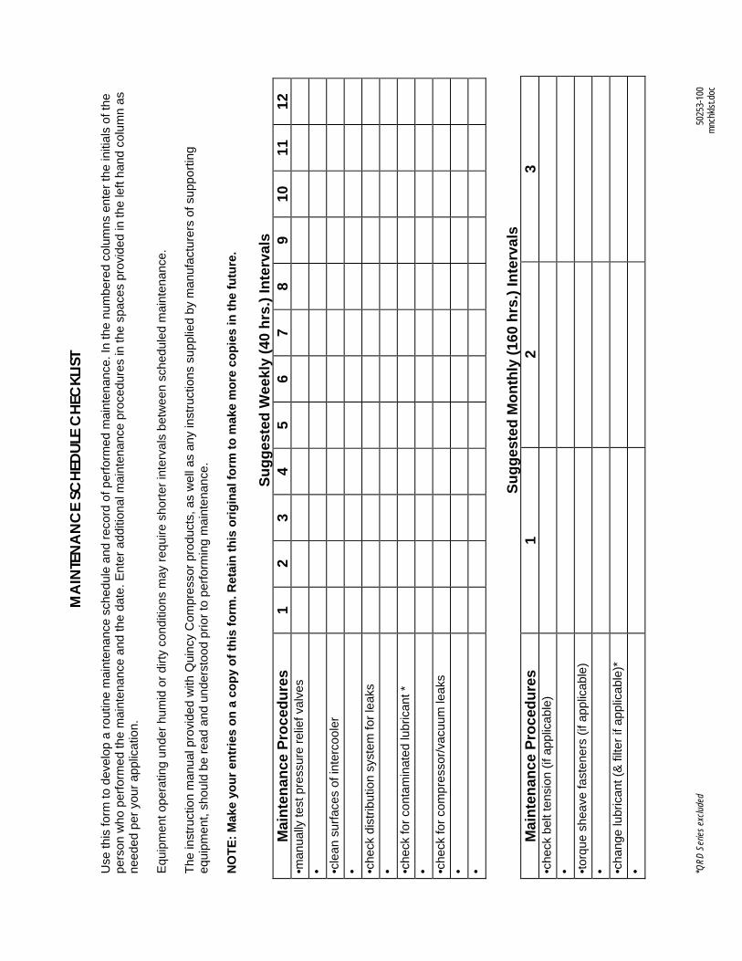
*QRD
Ser
ies e
xclud
ed
5025
3-10
0
mn
chkls
t.doc
MA
INTE
NA
NC
E SC
HEDU
LE C
HEC
KLIS
T
Use
this
form
to d
evel
op a
rout
ine
mai
nten
ance
sch
edul
e an
d re
cord
of p
erfo
rmed
mai
nten
ance
. In
the
num
bere
d co
lum
ns e
nter
the
initi
als
of th
e pe
rson
who
per
form
ed th
e m
aint
enan
ce a
nd th
e da
te. E
nter
add
ition
al m
aint
enan
ce p
roce
dure
s in
the
spac
es p
rovi
ded
in th
e le
ft ha
nd c
olum
n as
ne
eded
per
you
r app
licat
ion.
E
quip
men
t ope
ratin
g un
der h
umid
or d
irty
cond
ition
s m
ay re
quire
sho
rter i
nter
vals
bet
wee
n sc
hedu
led
mai
nten
ance
. Th
e in
stru
ctio
n m
anua
l pro
vide
d w
ith Q
uinc
y C
ompr
esso
r pro
duct
s, a
s w
ell a
s an
y in
stru
ctio
ns s
uppl
ied
by m
anuf
actu
rers
of s
uppo
rting
eq
uipm
ent,
shou
ld b
e re
ad a
nd u
nder
stoo
d pr
ior t
o pe
rform
ing
mai
nten
ance
. N
OTE
: Mak
e yo
ur e
ntrie
s on
a c
opy
of th
is fo
rm. R
etai
n th
is o
rigin
al fo
rm to
mak
e m
ore
copi
es in
the
futu
re.
Su
gges
ted
Wee
kly
(40
hrs.
) Int
erva
ls
Mai
nten
ance
Pro
cedu
res
1 2
3 4
5 6
7 8
9 10
11
12
•m
anua
lly te
st p
ress
ure
relie
f val
ves
•
•c
lean
sur
face
s of
inte
rcoo
ler
•
•c
heck
dis
tribu
tion
syst
em fo
r lea
ks
•
•c
heck
for c
onta
min
ated
lubr
ican
t *
•
•c
heck
for c
ompr
esso
r/vac
uum
leak
s
•
•
Sugg
este
d M
onth
ly (1
60 h
rs.)
Inte
rval
s M
aint
enan
ce P
roce
dure
s 1
2 3
•che
ck b
elt t
ensi
on (i
f app
licab
le)
•
•to
rque
she
ave
fast
ener
s (if
app
licab
le)
•
•c
hang
e lu
bric
ant (
& fi
lter i
f app
licab
le)*
•

Reciprocating / Systems: 217.222.7700
Air Master 217.277.0270
E-mail: [email protected]
Website: quincycompressor.com