PROPRIETARY AND CONFIDENTIAL Spirent TestCenter Testing MPLS QoS Setting the MPLS EXP bits.
800 East 96th StreetIndianapolis, IN 46240 USA
Cisco Press
QoS for IP/MPLS Networks
Santiago Alvarez
ii
QoS for IP/MPLS Networks
Santiago Alvarez
Copyright© 2006 Cisco Systems, Inc.
Published by:Cisco Press800 East 96th Street Indianapolis, IN 46240 USA
All rights reserved. No part of this book may be reproduced or transmitted in any form or by any means, electronic or mechanical, including photocopying, recording, or by any information storage and retrieval system, without writ-ten permission from the publisher, except for the inclusion of brief quotations in a review.
Printed in the United States of America 1 2 3 4 5 6 7 8 9 0
First Printing June 2006
Trademark Acknowledgments
All terms mentioned in this book that are known to be trademarks or service marks have been appropriately capital-ized. Cisco Press or Cisco Systems, Inc. cannot attest to the accuracy of this information. Use of a term in this book should not be regarded as affecting the validity of any trademark or service mark.
Warning and Disclaimer
This book is designed to provide information about quality of service in IP/MPLS networks using Cisco IOS and Cisco IOS XR. Every effort has been made to make this book as complete and as accurate as possible, but no war-ranty or fitness is implied.
The information is provided on an “as is” basis. The authors, Cisco Press, and Cisco Systems, Inc. shall have neither liability nor responsibility to any person or entity with respect to any loss or damages arising from the information contained in this book or from the use of the discs or programs that may accompany it.
The opinions expressed in this book belong to the author and are not necessarily those of Cisco Systems, Inc.
Corporate and Government Sales
Cisco Press offers excellent discounts on this book when ordered in quantity for bulk purchases or special sales.
For more information please contact:
U.S. Corporate and Government Sales
1-800-382-3419 [email protected]
For sales outside the U.S. please contact:
International Sales
Feedback Information
At Cisco Press, our goal is to create in-depth technical books of the highest quality and value. Each book is crafted with care and precision, undergoing rigorous development that involves the unique expertise of members from the professional technical community.
Library of Congress Cataloging-in-Publication Number is on file.
ISBN: 1-58714-391-7
iii
Readers’ feedback is a natural continuation of this process. If you have any comments regarding how we could improve the quality of this book, or otherwise alter it to better suit your needs, you can contact us through e-mail at [email protected]. Please make sure to include the book title and ISBN in your message.
We greatly appreciate your assistance.
Publisher Paul BogerCisco Representative Anthony WolfendenCisco Press Program Manager Jeff BradyProduction Manager Patrick KanouseDevelopment Editor Jill BatistickSenior Project Editor San Dee PhillipsCopy Editor Keith ClineTechnical Editors Mark Gallo, Raymond ZhangBook and Cover Designer Louisa AdairComposition Mark ShirarIndexer Keith Cline
iv
About the Author
Santiago Alvarez, CCIE No. 3621, is a technical marketing engineering for Cisco Systems working on MPLS and QoS since 2000. He joined Cisco in the blazing days of 1997. Prior to Cisco, Santiago worked in software development for Lucent Technologies. He has been involved with computer net-working since 1991. Santiago is a frequent speaker at Cisco Networkers and a periodic contributor to
Cisco Packet
Magazine
.
He holds a bachelor of science degree in computer science from EAFIT Uni-versity, a master of Science degree in computer science from Colorado State University, and a master of science in telecommunications from the University of Colorado at Boulder. Outside work, he enjoys the outdoors, fine food, and exploring the world as an independent traveler. He can be reached at [email protected].
v
About the Technical Reviewers
Mark Gallo
is a systems engineering manager at Cisco Systems within the channels organization. He has led several engineering groups responsible for positioning and delivering Cisco end-to-end systems, as well as designing and implementing enterprise LANs and international IP networks. He has a B.S. degree in electrical engineering from the University of Pittsburgh and holds Cisco CCNP and CCDP certifications. Mark resides in northern Virginia with his wife, Betsy, and son, Paul.
Raymond Zhang
is a senior network architect for BT Infonet in the areas of Global IP backbone infra-structure, routing architecture design, planning, and its evolutions. Currently, his main areas of interest include large-scale backbone routing, traffic engineering, performance and traffic statistical analysis, and MPLS-related technologies (including interdomain traffic engineering, GMPLS, metro Ethernet, Diffserve, IPv6, and Multicast). Raymond participates in several IETF drafts relating to MPLS, BGP-based MPLS VPN, Inter-AS TE, and, more recently, PCE-based work.

vi
Dedications
Thanks for withstanding long, long working hours.
vii
Acknowledgments
I would like to give special thanks to Bob Olsen and Sandeep Bajaj for sharing their technical expertise through so many years. They have patiently tolerated my constant interruptions and have provided use-ful insight on different topics included in the book.
Special thanks to the reviewers, Mark Gallo and Raymond Zhang. I appreciate your detailed comments. I am to blame for any remaining inaccuracies or omissions.
Big thanks to Bruce Davie, whose responsiveness at key points encouraged me to persist in my goal. I highly regard his unusual ability to abstract complexity and clearly illustrate the essence of intricate technology concepts. Much of his work has directly and indirectly influenced the content of this book. Similarly, I extend my gratitude to François Le Faucheur and Jean Philippe Vasseur. They have had the patience to discuss with me many aspects of these technologies in numerous occasions.
Merci!
Thanks to Ramesh Uppili for contributing to the presentation of key topics in multiple ways.
I also want to thank Rakesh Gandi, Prashanth Yelandur, Ashish Savla, Bobby Kaligotla, Lawrence Wobker, Ashok Ganesan, Jay Thontakudi, and Scott Yow for facilitating the discussion of Cisco IOS XR in this book.
Special thanks to the Cisco Press team: John Kane, Chris Cleveland, Jill Batistick, San Dee Phillips, and Elizabeth Peterson. I really appreciate your attention to detail and extraordinary patience with me. I wish John the best in his new endeavors.
Finally, if you have read this far in search of your name, this paragraph is for you. I have to acknowledge that numerous individuals contributed through insightful discussions. They unhappily or maybe happily remain anonymous. Thanks!

This page intentionally left blank
ix
Contents at a Glance
Foreword xv
Introduction xvii
Chapter 1
QoS Technology Overview 3
Chapter 2
MPLS TE Technology Overview 57
Chapter 3
Cisco QoS 79
Chapter 4
Cisco MPLS Traffic Engineering 143
Chapter 5
Backbone Infrastructure 201
Appendix A
Command Reference for Cisco MPLS Traffic Engineering and RSVP 265
Index
282
x
Contents
Foreword xv
Introduction xvii
Chapter 1
QoS Technology Overview 3
IP QoS Architectures 3
Integrated Services 4IntServ Terminology 5Architecture Principles 5Service Model 6Use of RSVP in IntServ 8
Differentiated Services 9DiffServ Terminology 9Architecture Principles 10Differentiated Services Code Point 11Nodes, Domains, and Regions 13Traffic Classification and Conditioning 13Per-Hop Behaviors 15
MPLS Support for IntServ 18
MPLS Support for DiffServ 19
E-LSP 20L-LSP 22DiffServ Tunneling Models over MPLS 25
Pipe Model 25Short-Pipe Model 26Uniform Model 28
Traffic-Management Mechanisms 31
Traffic Classification 31Traffic Marking 31Traffic Policing 32Traffic Shaping 35Congestion Management 37Active Queue Management 40Link Fragmentation and Interleaving 42Header Compression 44
QoS Signaling 45
Resource Reservation Protocol 45Design Principles 46Protocol Messages 47Protocol Operation 49
Other QoS Signaling Mechanisms 51
xi
Summary 52
References 52
Chapter 2
MPLS TE Technology Overview 57
MPLS TE Introduction 57
Basic Operation of MPLS TE 59
Link Information Distribution 59Path Computation 60TE LSP Signaling 63Traffic Selection 64
DiffServ-Aware Traffic Engineering 64
Class-Types and TE-Classes 66Bandwidth Constraints 68
Maximum Allocation Model 68Russian Dolls Model 70
Fast Reroute 71
Link Protection 74Node Protection 74
Summary 76
References 77
Chapter 3
Cisco QoS 79
Cisco QoS Behavioral Model 79
Classification Component 80Pre-Queuing Component 80Queuing Component 81
Enqueuing Subcomponent 81Dequeuing Subcomponent 82
Post-Queuing Component 84
Modular QoS Command-Line Interface 84
Hardware Support for the MQC 87Traffic-Management Mechanisms 87
Traffic Classification 88Traffic Marking 94Traffic Policing 100Traffic Shaping 108Congestion Management 115Active Queue Management 121Link Fragmentation and Interleaving 127Header Compression 128
Hierarchical Configurations 129Hierarchical Classification 129
xii
Hierarchical Policies 130Percentage-Based Rates 132Parameter Units 133Processing of Local Traffic 135
Summary 139
References 140
Chapter 4
Cisco MPLS Traffic Engineering 143
Basic Operation of MPLS TE 143
Enabling MPLS TE 144Enabling MPLS TE on a Node 144Enabling MPLS TE on an Interface 145
Defining a TE Tunnel Interface 146Link Information Distribution 148
Using IS-IS for Link Information Distribution 148Using OSPF for Link Information Distribution 149Controlling Flooding 150Configuring Link Attributes 150Verifying Link Information Distribution 153
Path Computation 156Configuring the TE LSP Path 156Configuring the TE LSP Constraints 157Path Reoptimization 159Verifying Path Computation 160
Signaling of TE LSPs 163Configuring RSVP 163Verifying RSVP 164Verifying Signaling of TE LSPs 167
Traffic Selection 172Traffic-Selection Alternatives 172Class-Based Tunnel Selection 173
DiffServ-Aware Traffic Engineering (DS-TE) 175
Prestandard DS-TE 175Class-Types and TE-Class 176Defining a DS-TE Tunnel Interface 177Configuring Bandwidth Constraints 179Verifying DS-TE Link Information Distribution 181Verifying Signaling of DS-TE LSPs 182
Fast Reroute (FRR) 182
Link and Node Protection 183Bandwidth Protection 187
xiii
Verifying FRR on the Headend 191Verifying FRR on the PLR 193
Summary 198
References 198
Chapter 5
Backbone Infrastructure 201
Backbone Performance 201
Performance Requirements for Different Applications 202Segmentation of Performance Targets 204Factors Affecting Performance Targets 206
Latency Versus Link Utilization 207
Reference Network 210
Edge Nodes 210
QoS Design Alternatives 212
Best-Effort Backbone 213Best-Effort Backbone with MPLS TE 219DiffServ Backbone 226DiffServ Backbone with MPLS TE 233DiffServ Backbone with DiffServ-Aware Traffic Engineering 240Adding MPLS TE FRR 251What Design Should I Use? 260
Summary 261
References 261
Appendix A
Command Reference for Cisco MPLS Traffic Engineering and RSVP 265
Index
282
xiv
Icons Used in This Book
Command Syntax Conventions
The conventions used to present command syntax in this book are the same conventions used in the IOS Command Reference. The Command Reference describes these conventions as follows:
•
Boldface
indicates commands and keywords that are entered literally as shown. In actual configuration examples and output (not general command syntax), boldface indicates commands that are manually input by the user (such as a
show
command).
•
Italics
indicate arguments for which you supply actual values.
• Vertical bars (|) separate alternative, mutually exclusive elements. Note, however, that the vertical bar (pipe operand) is also used to filter command-line interface command output; in that scenario, the operand (
|
) precedes the
begin
,
exclude
, or
include
keywords, which are then followed by a regular expression.
• Square brackets [ ] indicate optional elements.
• Braces { } indicate a required choice.
• Braces within brackets [{ }] indicate a required choice within an optional element.
PC PC withSoftware
SunWorkstation
Macintosh
Terminal File Server
WebServer
Cisco WorksWorkstation
Printer Laptop IBMMainframe
Front EndProcessor
ClusterController
Modem
DSU/CSU
Router Bridge Hub DSU/CSU CatalystSwitch
MultilayerSwitch
ATMSwitch
ISDN/Frame RelaySwitch
CommunicationServer
Gateway
AccessServer
Network Cloud
TokenRing
Token Ring
Line: Ethernet
FDDI
FDDI
Line: Serial Line: Switched Serial
xv
Foreword
The phrase “IP QoS” was for many years considered an oxymoron. Indeed, much of the success of the IP architecture could be traced to its adoption of a "best effort" service model, enabling IP to run over just about any underlying network technology. Best effort service, however, is defined by a lack of assurance that packets will be delivered in a timely manner, or even delivered at all. Such a service model limits the potential of IP networks to support applications that demand timely packet delivery, such as interactive telephony and multimedia applications.
As far back as 1979, there were proposals to extend the IP service model to support applications with stronger QoS requirements. However, this remained a research topic until the early 1990s. By that point, the idea of convergence—carrying many applications with diverse QoS needs on a single network—was gaining currency, although the word “convergence” would not become a buzzword for several years. ATM was widely expected to be the packet switching technology that would enable this convergence, but a concerted effort to add QoS to IP was also getting underway. The seminal 1992 paper by Clark, Shenker, and Zhang on support of real-time applications in the Internet put a serious stake in the ground for IP QoS, and work at the IETF to standardize a set of IP QoS mechanisms began shortly thereafter. The Integrated Services architecture and Resource Reservation Protocol resulted, and the Differentiated Services architecture followed.
Another technical development with big implications for IP QoS was Multiprotocol Label Switching, which grew out of work on Tag Switching at Cisco begun in 1996. There was considerable confusion about exactly what impact MPLS would have on IP QoS, in part because of the resemblances between MPLS and ATM, which had its own QoS model. In reality, the biggest single effect MPLS had on QoS was to add another tool to the QoS toolbox, in the form of traffic engineering with constraint-based rout-ing. It is for this reason more than any other that MPLS and QoS deserve to be covered in a single book.
Which brings us to the current volume. IP QoS can now be considered a mature technology, not just something for the bleeding edge. It is also notoriously complex to understand and to configure cor-rectly. Some of this complexity is intrinsic; some is an accident of history. On the intrinsic side, under-standing QoS is hard because it requires the ability to operate at many different levels of abstraction. One needs to understand the high level QoS architectures, to have a behavioral model of QoS features inside a router, to know how those features map onto a particular piece of hardware, and to understand the CLI that is used to control those features. This is where this book sets itself apart from the pack of QoS books. Some cover QoS architecture and IETF standards. Some provide information on CLI com-mands. But this is the only book I've found that walks the reader through the levels of abstraction from high level architecture to low level CLI, with a clear explanation of the abstract QoS behavior model that all routers support providing the bridge between the levels. By reading this book, you will under-stand both the big picture of QoS and the details necessary to deploy it in a real network.
Another factor that made QoS difficult to manage in the past was a somewhat ad hoc approach to its implementation. Combinations of features were sometimes implemented in a monolithic way, and inconsistency across platforms was the norm. This situation has improved massively in recent years, notably with the adoption of the Modular QoS CLI across most of the Cisco product line. Thus, QoS deployment is much more straightfoward than it once was, and this book's timely coverage of the MQC and its underlying behavioral model will make it even easier.
xvi
Many readers may be tempted to jump straight to the last chapter's guidance on how to design and deploy a QoS strategy in a backbone network. Santiago's extensive real-world deployment experience certainly makes this chapter especially valuable. However, the preceding four chapters are the ones that will provide you with a fundamental understanding of QoS. Thus, rather than blindly following a QoS "recipe," you'll be able to make the right design decisions to meet the needs of your own applications and customers. If you really want to understand QoS fully, this is the book to read, from start to finish.
Bruce DavieCisco Fellow
.
xvii
Introduction
The motivation behind this book is the continued interest in the implementation of
quality of service
(QoS) in IP/MPLS networks. QoS arises as a key requirement for these networks, which have become the preferred technology platform for building converged networks that support multiple services. The topic can be one of the most complex aspects of the network design, implementation, and operation. Despite the importance of and interest in this topic, no other Cisco Press title provides a detailed discus-sion of this subject. A significant amount of the content of this book also applies to pure IP networks that do not have immediate plans to migrate to a full IP/MPLS network.
This material covers both QoS and
Multiprotocol Label Switching Traffic Engineering
(MPLS TE). In particular, it covers MPLS TE as a technology that complements traditional QoS technologies. MPLS TE can be an instrumental tool to improve the QoS guarantees that an IP/MPLS network offers. As such, it can contribute to improving both network performance and availability. However, this book pro-vides a concise discussion of MPLS TE. Those readers interested in further information should consult the Cisco Press title
Traffic Engineering with MPLS
.
The book takes the point of view of those individuals responsible for the IP/MPLS network. Other Cisco Press titles describe the details of the QoS implementation for those devices receiving the services that the network offers.
You should have a basic understanding of both IP and MPLS to obtain the most benefit from this book. That understanding should include basic IP addressing and routing, along with the basics of MPLS for-warding. However, the book provides a technology overview of QoS and MPLS TE to help those with less exposure to these technologies or to serve as a review/reference to those more familiar with those topics.
This book touches a broad topic and does not pretend to address all QoS aspects of interest. You can expect future Cisco Press books to cover important areas, including the following:
• Implementation of QoS for specific services (for instance, IP, Ethernet, ATM)
• QoS management (including monitoring and provisioning)
• Interprovider QoS
Visit this book’s website, http://www.ciscopress.com/title/1587052334, for further information.
xviii
Who Should Read This Book?
This book’s primary audience is the technical staff of those organizations building IP/MPLS networks as an infrastructure to provide multiple services. The material includes technology, configuration, and operational details to help in the design, implementation, and operation of QoS in IP/MPLS networks. Service providers are a prime example of the organizations that this book targets. However, government agencies, educational institutions, and large enterprises pursuing IP/MPLS will find the material equally useful.
A secondary audience for this book is those individuals in charge of service definition or those individu-als subscribing to network services. Both types can benefit from a better understanding of the differenti-ation capabilities that IP/MPLS networks can offer.
How This Book Is Organized
Although this book could be read cover to cover, it is designed to be flexible and allow you to easily move between chapters and sections of chapters to cover just the material that you need more work with. The content is roughly divided into three parts:
• Chapters 1 and 2 provide a technology overview.
• Chapters 3 and 4 discuss Cisco implemenation.
• Chapter 5 covers different backbone design options.
Here is a brief synopsis of each chapter:
Chapter 1, “QoS Technology Overview”
—This chapter provides a review of QoS technology for IP and IP/MPLS networks. The chapter initially discusses the IP QoS architectures and how they apply to MPLS. Multiple sections elaborate on MPLS support for
Differentiated Services
(DiffServ), including a detailed discussion on
EXP-inferred-class link switched path
(E-LSP),
Label-inferred-class LSP
(L-LSP), and DiffServ tunneling models (pipe, short pipe, and uniform). This dicussion leads into a sum-mary of traffic-management mechanisms with a detailed look at traffic policing, traffic shaping, traffic scheduling, active queue manangemt, and so on. The chapter also discusses QoS signaling with a focus on the
Resource Reservation Protocol
(RSVP).
Chapter 2, “MPLS TE Technology Overview”
—This chapter reviews the basic operation of this tech-nology with its DiffServ extensions and applicability as a traffic-protection alternative. This review elaborates on the concepts of contraint-based routing,
DiffServ-aware Traffic Engineering
(DS-TE) and
fast reroute
(FRR) (including link, shared-risk link group, and node protection).
Chapter 3, “Cisco QoS”
—This chapter covers the Cisco QoS behavioral model and the
modular QoS command-line interface
(MCQ). The chapter abstracts the platform specifics to facilitate the under-standing of Cisco QoS and provides a complete reference of the configuration commands. In addition, the chapter includes numerous examples to illustrate the configuration and verification of different traf-fic-management mechanisms in Cisco IOS and Cisco IOS XR. This material is equially relevant to IP and IP/MPLS networks.
xix
Chapter 4, “Cisco MPLS Traffic Engineering”
—This chapter presents Cisco implementation of MPLS Traffic Engineering in both Cisco IOS and Cisco IOS XR. It includes multiple configuration and verification examples illustrating the implementation of basic MPLS TE, DS-TE, and FRR.
Chapter 5, “Backbone Infrastructure”
—This chapter discusses the backbone performance require-ments and the different design options. The chapter reviews different designs, ranging from a best-effort backbone to the most elaborate scenarios combining DiffServ, DS-TE, and FRR. Numerous configura-tion examples illustrate their implementation using Cisco IOS and Cisco IOS XR.

In this chapter, you learn the following topics:
• Cisco QoS Behavioral Model
• The Modular QoS Command-Line Interface
C H A P T E R 3
Cisco QoSThis chapter provides an overview of the quality of service (QoS) implementation and con-figuration in Cisco products. This overview includes details about algorithms and configu-ration commands. The material includes simple examples to illustrate the use of the commands. Chapter 5, “Backbone Infrastrusture,” provides more elaborate examples. You will find details about both Cisco IOS and Cisco IOS XR implementations. This chapter does not include platform or hardware details because of their constant evolution. The material assumes that you are already familiar with the technology aspects of QoS. Chapter 1, “QoS Technology Overview,” includes a technology overview that you can use as a reference.
Cisco QoS Behavioral ModelCisco uses an abstract QoS behavioral model that provides consistency across devices. Cisco platforms may ultimately use different internal QoS implementations. However, the Cisco QoS behavioral model provides a common abstraction that hides the implementation details and facilitates the implementation of QoS across different product families. The model is flexible enough to provide a wide range of possible QoS behaviors despite its sim-plicity. A good understanding of this model will help you comprehend QoS configuration on Cisco devices. Later sections in this chapter present an overview of QoS configuration commands and their relationship with this model.
The QoS behavioral model relies on the concept of a traffic-management node (TMN). This concept represents an abstraction of a collection of QoS actions that a device applies to traffic at a particular point during packet forwarding. The TMN identifies one or more traffic streams and defines the actions performed on each stream. The underlying imple-mentation infers what structures and mechanisms (including possible queues) will provide the behavior that the TMN actions define.
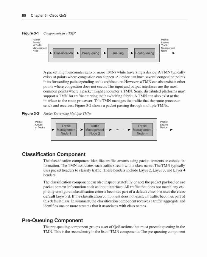
The TMN has four components, in the following order: classification, pre-queuing, queuing, and post-queuing. All components are optional and user configurable. Figure 3-1 provides a functional view of a packet traversing a TMN. The next sections provide more details on these components.
80 Chapter 3: Cisco QoS
Figure 3-1 Components in a TMN
A packet might encounter zero or more TMNs while traversing a device. A TMN typically exists at points where congestion can happen. A device can have several congestion points in its forwarding path depending on its architecture. However, a TMN can also exist at other points where congestion does not occur. The input and output interfaces are the most common points where a packet might encounter a TMN. Some distributed platforms may support a TMN for traffic entering their switching fabric. A TMN can also exist at the interface to the route processor. This TMN manages the traffic that the route processor sends and receives. Figure 3-2 shows a packet passing through multiple TMNs.
Figure 3-2 Packet Traversing Multiple TMNs
Classification ComponentThe classification component identifies traffic streams using packet contents or context in-formation. The TMN associates each traffic stream with a class name. The TMN typically uses packet headers to classify traffic. These headers include Layer 2, Layer 3, and Layer 4 headers.
The classification component can also inspect (statefully or not) the packet payload or use packet context information such as input interface. All traffic that does not match any ex-plicitly configured classification criteria becomes part of a default class that uses the class-default keyword. If the classification component does not exist, all traffic becomes part of this default class. In summary, the classification component receives a traffic aggregate and identifies one or more streams that it associates with class names.
Pre-Queuing ComponentThe pre-queuing component groups a set of QoS actions that must precede queuing in the TMN. This is the second entry in the list of TMN components. The pre-queuing component
Classification Pre-queuing Queuing Post-queuing
PacketArrivesat TrafficManagementNode
PacketLeavesTrafficManagementNode
TrafficManagement
Node 1
TrafficManagement
Node 2…
TrafficManagement
Node n
PacketArrivesat Device
PacketLeavesDevice
Cisco QoS Behavioral Model 81
always follows the classification component. It includes actions such as policing, marking, dropping, and header compression. Despite its name, this component does not imply that a queuing component must exist in every TMN. However, the prequeuing component must precede a queuing component if one exists.
The pre-queuing component can affect the operation of subsequent components. For instance, a policing action may re-mark packets. The new packet marking would affect any active queue management in the queuing component. The pre-queuing component does not affect the result of the classification component. That is, the TMN does not reclassify packets.
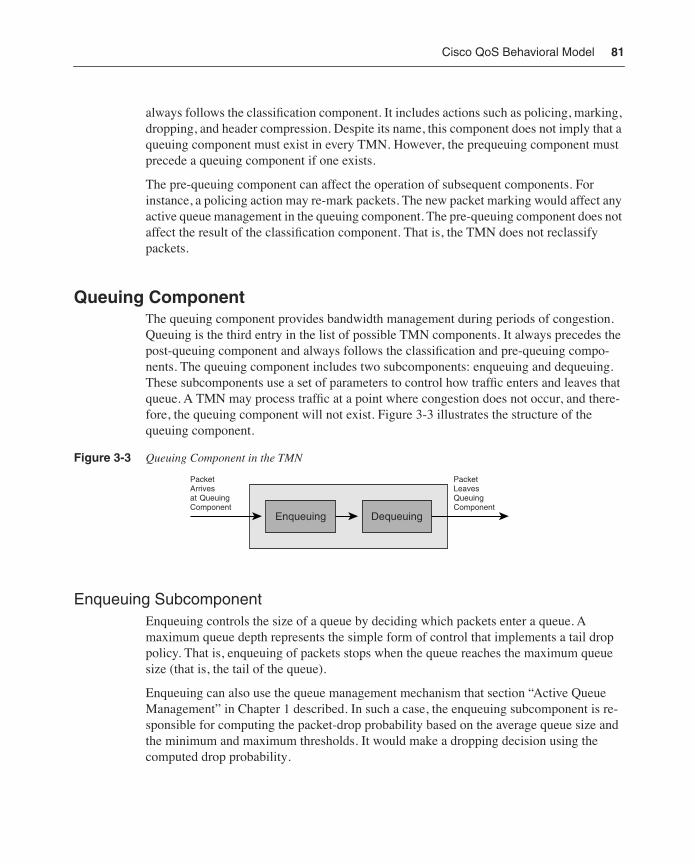
Queuing ComponentThe queuing component provides bandwidth management during periods of congestion. Queuing is the third entry in the list of possible TMN components. It always precedes the post-queuing component and always follows the classification and pre-queuing compo-nents. The queuing component includes two subcomponents: enqueuing and dequeuing. These subcomponents use a set of parameters to control how traffic enters and leaves that queue. A TMN may process traffic at a point where congestion does not occur, and there-fore, the queuing component will not exist. Figure 3-3 illustrates the structure of the queuing component.
Figure 3-3 Queuing Component in the TMN
Enqueuing SubcomponentEnqueuing controls the size of a queue by deciding which packets enter a queue. A maximum queue depth represents the simple form of control that implements a tail drop policy. That is, enqueuing of packets stops when the queue reaches the maximum queue size (that is, the tail of the queue).
Enqueuing can also use the queue management mechanism that section “Active Queue Management” in Chapter 1 described. In such a case, the enqueuing subcomponent is re-sponsible for computing the packet-drop probability based on the average queue size and the minimum and maximum thresholds. It would make a dropping decision using the computed drop probability.
Enqueuing Dequeuing
PacketArrivesat QueuingComponent
PacketLeavesQueuingComponent
82 Chapter 3: Cisco QoS
Dequeuing SubcomponentThe dequeuing subcomponent controls packet departure from queues. It represents an ab-straction of the scheduling and shaping mechanisms that sections “Traffic Shaping” and “Congestion Management” presented in Chapter 1. Four attributes can influence traffic de-queuing:
• The minimum-bandwidth guarantee represents the worst-case bandwidth allocation that the queue will receive.
• The maximum bandwidth defines the best-case bandwidth allocation for the queue. In some cases, it corresponds to a shaper rate.
• The excess bandwidth defines the distribution of excess bandwidth beyond the minimum-bandwidth guarantee.
• The priority attribute defines whether the scheduler must service a queue ahead of all other queues of lower priority.
The configuration flexibility of the queue attributes defines two-parameter versus three-parameter schedulers. A TMN uses a two-parameter scheduler if the minimum and maximum bandwidth guarantees are independent, whereas the excess bandwidth depends on one of the other two guarantees (typically, the minimum guarantee). Therefore, the con-figuration of the minimum and excess bandwidths is mutually exclusive. One parameter implies the other. A TMN with a three-parameter scheduler supports the independent con-figuration of minimum, maximum, and excess bandwidth amounts for each queue. This configuration flexibility allows a TMN to offer more varied behaviors. In particular, a queue can provide better latency and jitter characteristics if it receives more excess bandwidth.
The TMN has implicit default values for the minimum, maximum, and excess-bandwidth attributes. If a queue does not have a configuration for a minimum-bandwidth guarantee, the scheduler will not guarantee any bandwidth to the queue. If the queue does not have a maximum bandwidth attribute, the queue can receive as much bandwidth as possible.
Two-parameter and three-parameter schedulers have a different default behavior for the excess-bandwidth attribute. Three-parameter schedulers share excess bandwidth equally among queues without an explicit excess-bandwidth configuration. Two-parameter sched-ulers share excess bandwidth proportionally to the minimum-bandwidth guarantee. If a minimum-bandwidth configuration does not exist, the scheduler shares the excess bandwidth equally.
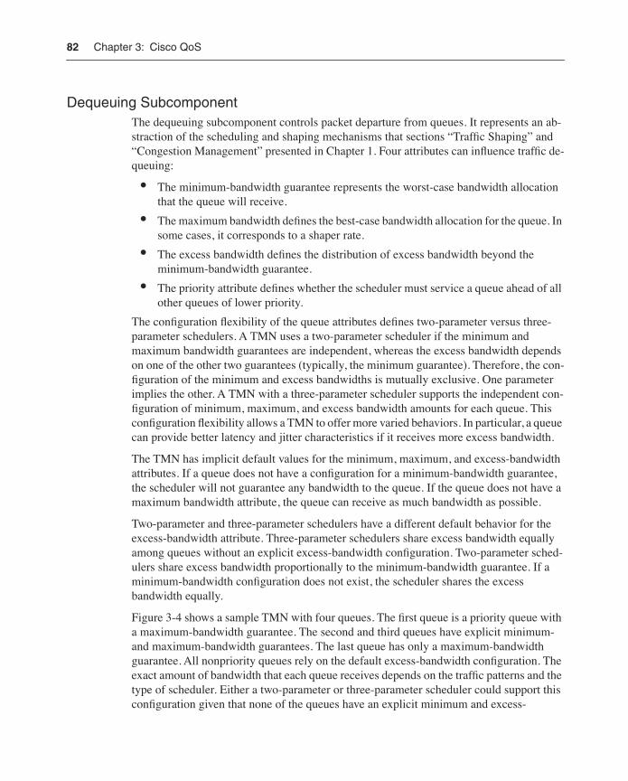
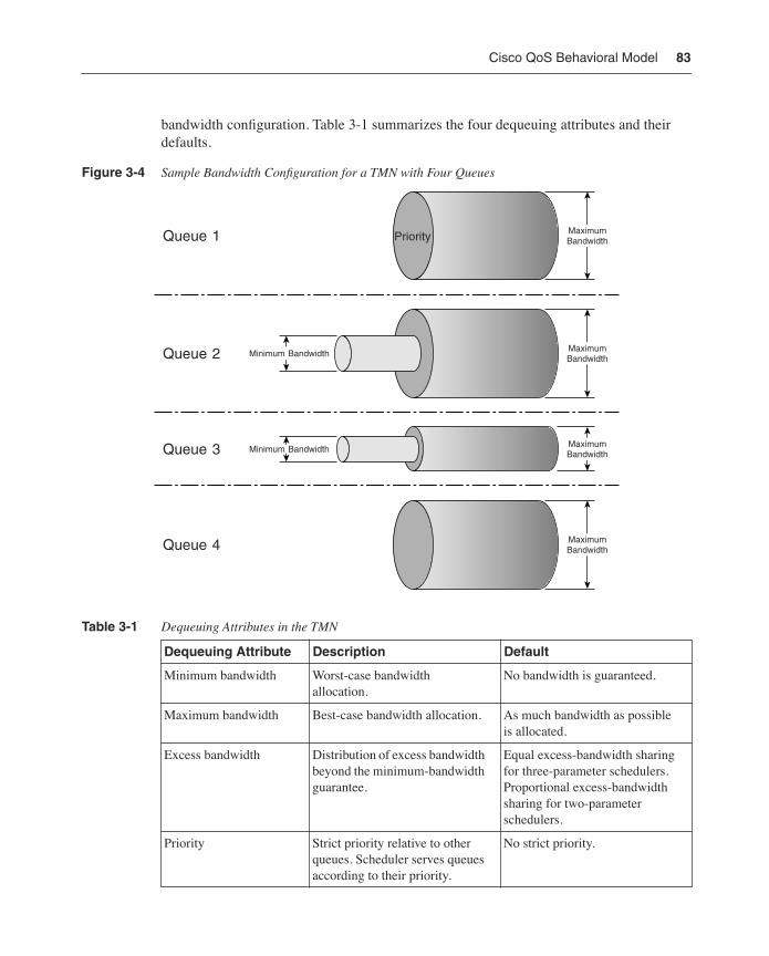
Figure 3-4 shows a sample TMN with four queues. The first queue is a priority queue with a maximum-bandwidth guarantee. The second and third queues have explicit minimum- and maximum-bandwidth guarantees. The last queue has only a maximum-bandwidth guarantee. All nonpriority queues rely on the default excess-bandwidth configuration. The exact amount of bandwidth that each queue receives depends on the traffic patterns and the type of scheduler. Either a two-parameter or three-parameter scheduler could support this configuration given that none of the queues have an explicit minimum and excess-
Cisco QoS Behavioral Model 83
bandwidth configuration. Table 3-1 summarizes the four dequeuing attributes and their defaults.
Figure 3-4 Sample Bandwidth Configuration for a TMN with Four Queues
Table 3-1 Dequeuing Attributes in the TMN
Dequeuing Attribute Description Default
Minimum bandwidth Worst-case bandwidth allocation.
No bandwidth is guaranteed.
Maximum bandwidth Best-case bandwidth allocation. As much bandwidth as possible is allocated.
Excess bandwidth Distribution of excess bandwidth beyond the minimum-bandwidth guarantee.
Equal excess-bandwidth sharing for three-parameter schedulers. Proportional excess-bandwidth sharing for two-parameter schedulers.
Priority Strict priority relative to other queues. Scheduler serves queues according to their priority.
No strict priority.
Minimum Bandwidth
MaximumBandwidth
MaximumBandwidth
MaximumBandwidthPriorityQueue 1
Queue 2
Queue 3
Queue 4 MaximumBandwidth
Minimum Bandwidth
84 Chapter 3: Cisco QoS
Post-Queuing ComponentThe post-queuing component defines the QoS actions that must follow queuing in the TMN. This is the fourth and last component of the TMN. It defines the last group of actions before the packet leaves the TMN.
This component is useful for actions where packet sequencing is important given that the queuing component generally reorders packets across queues. As an example, some com-pression mechanisms use sequence numbers and packets should receive their respective sequence number when the queuing component schedules the packet for transmission. As with the pre-queuing component, this component does not imply that a queuing component must exist. However, it must follow it if present.
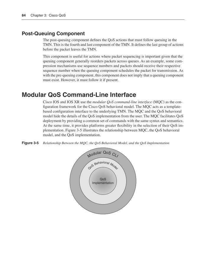
Modular QoS Command-Line InterfaceCisco IOS and IOS XR use the modular QoS command-line interface (MQC) as the con-figuration framework for the Cisco QoS behavioral model. The MQC acts as a template-based configuration interface to the underlying TMN. The MQC and the QoS behavioral model hide the details of the QoS implementation from the user. The MQC facilitates QoS deployment by providing a common set of commands with the same syntax and semantics. At the same time, it provides platforms greater flexibility in the selection of their QoS im-plementation. Figure 3-5 illustrates the relationship between MQC, the QoS behavioral model, and the QoS implementation.
Figure 3-5 Relationship Between the MQC, the QoS Behavioral Model, and the QoS Implementation
Modular QoS CLI
QoSImplementation
QoSBehavioral Model
Modular QoS Command-Line Interface 85
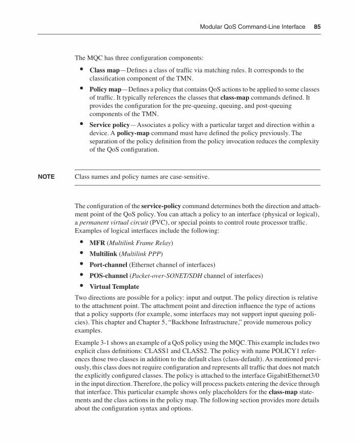
The MQC has three configuration components:
• Class map—Defines a class of traffic via matching rules. It corresponds to the classification component of the TMN.
• Policy map—Defines a policy that contains QoS actions to be applied to some classes of traffic. It typically references the classes that class-map commands defined. It provides the configuration for the pre-queuing, queuing, and post-queuing components of the TMN.
• Service policy—Associates a policy with a particular target and direction within a device. A policy-map command must have defined the policy previously. The separation of the policy definition from the policy invocation reduces the complexity of the QoS configuration.
NOTE Class names and policy names are case-sensitive.
The configuration of the service-policy command determines both the direction and attach-ment point of the QoS policy. You can attach a policy to an interface (physical or logical), a permanent virtual circuit (PVC), or special points to control route processor traffic. Examples of logical interfaces include the following:
• MFR (Multilink Frame Relay)
• Multilink (Multilink PPP)
• Port-channel (Ethernet channel of interfaces)
• POS-channel (Packet-over-SONET/SDH channel of interfaces)
• Virtual Template
Two directions are possible for a policy: input and output. The policy direction is relative to the attachment point. The attachment point and direction influence the type of actions that a policy supports (for example, some interfaces may not support input queuing poli-cies). This chapter and Chapter 5, “Backbone Infrastructure,” provide numerous policy examples.
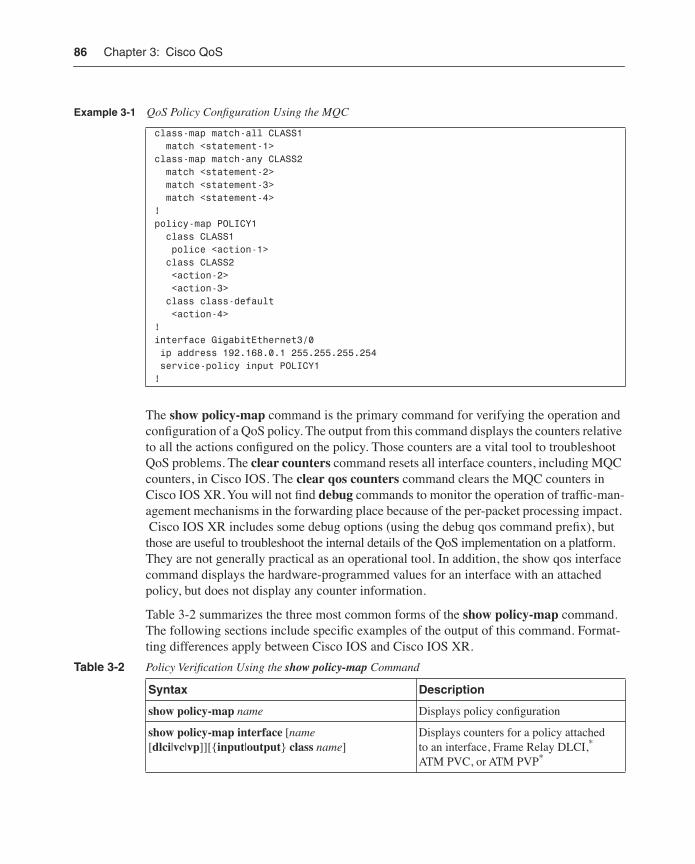
Example 3-1 shows an example of a QoS policy using the MQC. This example includes two explicit class definitions: CLASS1 and CLASS2. The policy with name POLICY1 refer-ences those two classes in addition to the default class (class-default). As mentioned previ-ously, this class does not require configuration and represents all traffic that does not match the explicitly configured classes. The policy is attached to the interface GigabitEthernet3/0 in the input direction. Therefore, the policy will process packets entering the device through that interface. This particular example shows only placeholders for the class-map state-ments and the class actions in the policy map. The following section provides more details about the configuration syntax and options.
86 Chapter 3: Cisco QoS
The show policy-map command is the primary command for verifying the operation and configuration of a QoS policy. The output from this command displays the counters relative to all the actions configured on the policy. Those counters are a vital tool to troubleshoot QoS problems. The clear counters command resets all interface counters, including MQC counters, in Cisco IOS. The clear qos counters command clears the MQC counters in Cisco IOS XR. You will not find debug commands to monitor the operation of traffic-man-agement mechanisms in the forwarding place because of the per-packet processing impact. Cisco IOS XR includes some debug options (using the debug qos command prefix), but those are useful to troubleshoot the internal details of the QoS implementation on a platform. They are not generally practical as an operational tool. In addition, the show qos interface command displays the hardware-programmed values for an interface with an attached policy, but does not display any counter information.
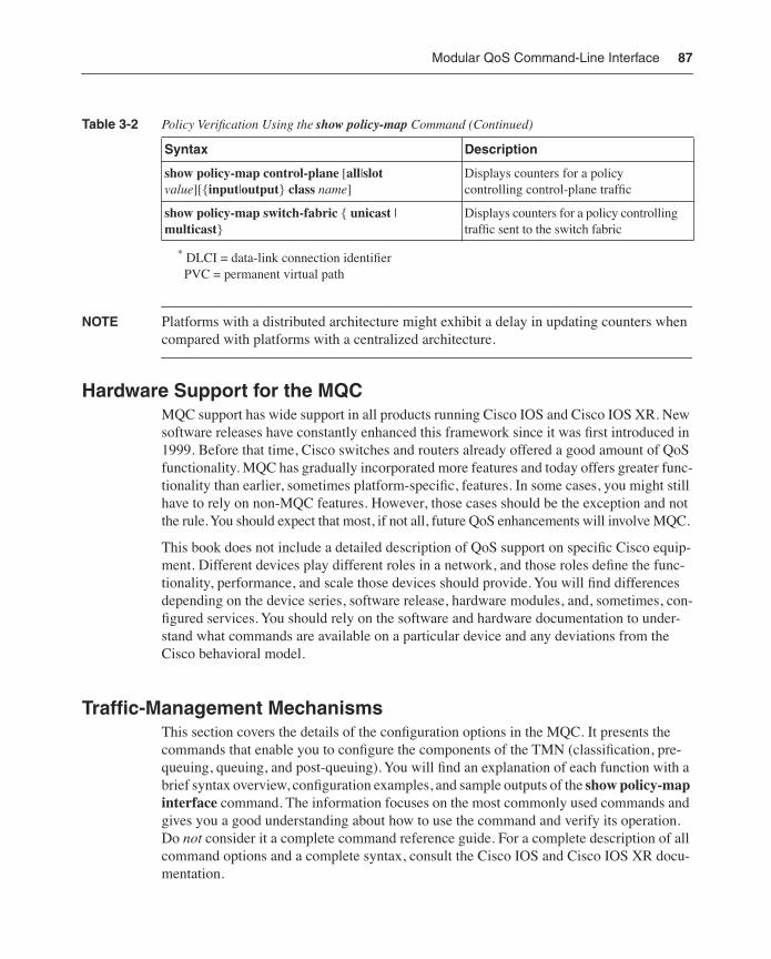
Table 3-2 summarizes the three most common forms of the show policy-map command. The following sections include specific examples of the output of this command. Format-ting differences apply between Cisco IOS and Cisco IOS XR.
Example 3-1 QoS Policy Configuration Using the MQC
class-map match-all CLASS1 match <statement-1> class-map match-any CLASS2 match <statement-2> match <statement-3> match <statement-4>! policy-map POLICY1 class CLASS1 police <action-1> class CLASS2 <action-2> <action-3> class class-default <action-4>!interface GigabitEthernet3/0 ip address 192.168.0.1 255.255.255.254 service-policy input POLICY1!
Table 3-2 Policy Verification Using the show policy-map Command
Syntax Description
show policy-map name Displays policy configuration
show policy-map interface [name [dlci|vc|vp]][{input|output} class name]
Displays counters for a policy attached to an interface, Frame Relay DLCI,* ATM PVC, or ATM PVP*
Modular QoS Command-Line Interface 87
* DLCI = data-link connection identifier PVC = permanent virtual path
NOTE Platforms with a distributed architecture might exhibit a delay in updating counters when compared with platforms with a centralized architecture.
Hardware Support for the MQCMQC support has wide support in all products running Cisco IOS and Cisco IOS XR. New software releases have constantly enhanced this framework since it was first introduced in 1999. Before that time, Cisco switches and routers already offered a good amount of QoS functionality. MQC has gradually incorporated more features and today offers greater func-tionality than earlier, sometimes platform-specific, features. In some cases, you might still have to rely on non-MQC features. However, those cases should be the exception and not the rule. You should expect that most, if not all, future QoS enhancements will involve MQC.
This book does not include a detailed description of QoS support on specific Cisco equip-ment. Different devices play different roles in a network, and those roles define the func-tionality, performance, and scale those devices should provide. You will find differences depending on the device series, software release, hardware modules, and, sometimes, con-figured services. You should rely on the software and hardware documentation to under-stand what commands are available on a particular device and any deviations from the Cisco behavioral model.
Traffic-Management MechanismsThis section covers the details of the configuration options in the MQC. It presents the commands that enable you to configure the components of the TMN (classification, pre-queuing, queuing, and post-queuing). You will find an explanation of each function with a brief syntax overview, configuration examples, and sample outputs of the show policy-map interface command. The information focuses on the most commonly used commands and gives you a good understanding about how to use the command and verify its operation. Do not consider it a complete command reference guide. For a complete description of all command options and a complete syntax, consult the Cisco IOS and Cisco IOS XR docu-mentation.
Syntax Description
show policy-map control-plane [all|slot value][{input|output} class name]
Displays counters for a policy controlling control-plane traffic
show policy-map switch-fabric { unicast | multicast}
Displays counters for a policy controlling traffic sent to the switch fabric
Table 3-2 Policy Verification Using the show policy-map Command (Continued)
88 Chapter 3: Cisco QoS
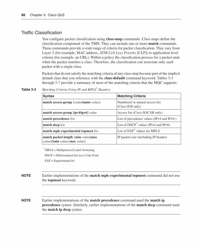
Traffic ClassificationYou configure packet classification using class-map commands. Class maps define the classification component of the TMN. They can include one or more match commands. These commands provide a wide range of criteria for packet classification. They vary from Layer 2 (for example, MAC address, ATM Cell Loss Priority [CLP]) to application level criteria (for example, an URL). Within a policy the classification process for a packet ends when the packet matches a class. Therefore, the classification can associate only each packet with a single class.
Packets that do not satisfy the matching criteria of any class map become part of the implicit default class that you reference with the class-default command keyword. Tables 3-3 through 3-7 provide a summary of most of the matching criteria that the MQC supports.
* MPLS = Multiprotocol Label Switching
DSCP = Differentiated Services Code Point
EXP = Experimental bit
NOTE Earlier implementations of the match mpls experimental topmost command did not use the topmost keyword.
NOTE Earlier implementations of the match precedence command used the match ip precedence syntax. Similarly, earlier implementations of the match dscp command used the match ip dscp syntax.
Table 3-3 Matching Criteria Using IP and MPLS* Headers
Syntax Matching Criteria
match access-group {value|name value} Numbered or named access list (Cisco IOS only)
match access-group [ipv4|ipv6] value Access list (Cisco IOS XR only)
match precedence list List of precedence values (IPv4 and IPv6 )
match dscp list List of DSCP* values (IPv4 and IPv6)
match mpls experimental topmost list List of EXP* values for MPLS
match packet length {min value[max value]|[min value] max value}
IP packet size (including IP header)
Modular QoS Command-Line Interface 89
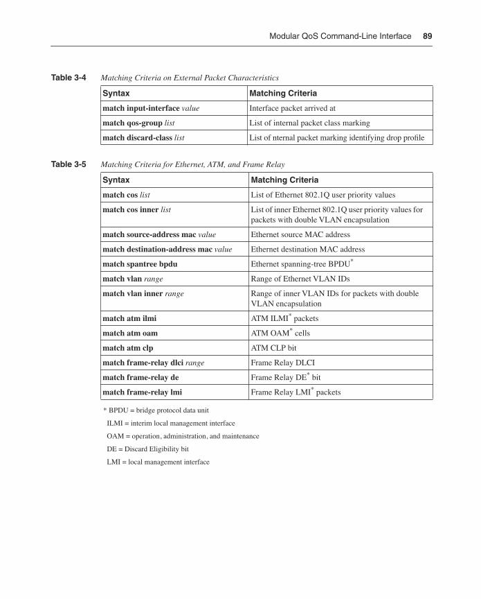
* BPDU = bridge protocol data unit
ILMI = interim local management interface
OAM = operation, administration, and maintenance
DE = Discard Eligibility bit
LMI = local management interface
Table 3-4 Matching Criteria on External Packet Characteristics
Syntax Matching Criteria
match input-interface value Interface packet arrived at
match qos-group list List of internal packet class marking
match discard-class list List of nternal packet marking identifying drop profile
Table 3-5 Matching Criteria for Ethernet, ATM, and Frame Relay
Syntax Matching Criteria
match cos list List of Ethernet 802.1Q user priority values
match cos inner list List of inner Ethernet 802.1Q user priority values for packets with double VLAN encapsulation
match source-address mac value Ethernet source MAC address
match destination-address mac value Ethernet destination MAC address
match spantree bpdu Ethernet spanning-tree BPDU*
match vlan range Range of Ethernet VLAN IDs
match vlan inner range Range of inner VLAN IDs for packets with double VLAN encapsulation
match atm ilmi ATM ILMI* packets
match atm oam ATM OAM* cells
match atm clp ATM CLP bit
match frame-relay dlci range Frame Relay DLCI
match frame-relay de Frame Relay DE* bit
match frame-relay lmi Frame Relay LMI* packets
90 Chapter 3: Cisco QoS
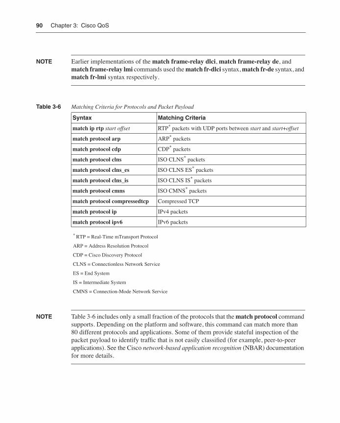
NOTE Earlier implementations of the match frame-relay dlci, match frame-relay de, and match frame-relay lmi commands used the match fr-dlci syntax, match fr-de syntax, and match fr-lmi syntax respectively.
* RTP = Real-Time mTransport Protocol
ARP = Address Resolution Protocol
CDP = Cisco Discovery Protocol
CLNS = Connectionless Network Service
ES = End System
IS = Intermediate System
CMNS = Connection-Mode Network Service
NOTE Table 3-6 includes only a small fraction of the protocols that the match protocol command supports. Depending on the platform and software, this command can match more than 80 different protocols and applications. Some of them provide stateful inspection of the packet payload to identify traffic that is not easily classified (for example, peer-to-peer applications). See the Cisco network-based application recognition (NBAR) documentation for more details.
Table 3-6 Matching Criteria for Protocols and Packet Payload
Syntax Matching Criteria
match ip rtp start offset RTP* packets with UDP ports between start and start+offset
match protocol arp ARP* packets
match protocol cdp CDP* packets
match protocol clns ISO CLNS* packets
match protocol clns_es ISO CLNS ES* packets
match protocol clns_is ISO CLNS IS* packets
match protocol cmns ISO CMNS* packets
match protocol compressedtcp Compressed TCP
match protocol ip IPv4 packets
match protocol ipv6 IPv6 packets
Modular QoS Command-Line Interface 91
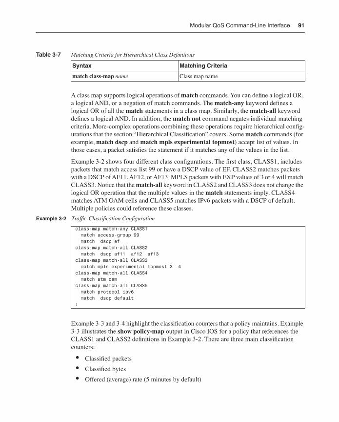
A class map supports logical operations of match commands. You can define a logical OR, a logical AND, or a negation of match commands. The match-any keyword defines a logical OR of all the match statements in a class map. Similarly, the match-all keyword defines a logical AND. In addition, the match not command negates individual matching criteria. More-complex operations combining these operations require hierarchical config-urations that the section “Hierarchical Classification” covers. Some match commands (for example, match dscp and match mpls experimental topmost) accept list of values. In those cases, a packet satisfies the statement if it matches any of the values in the list.
Example 3-2 shows four different class configurations. The first class, CLASS1, includes packets that match access list 99 or have a DSCP value of EF. CLASS2 matches packets with a DSCP of AF11, AF12, or AF13. MPLS packets with EXP values of 3 or 4 will match CLASS3. Notice that the match-all keyword in CLASS2 and CLASS3 does not change the logical OR operation that the multiple values in the match statements imply. CLASS4 matches ATM OAM cells and CLASS5 matches IPv6 packets with a DSCP of default. Multiple policies could reference these classes.
Example 3-3 and 3-4 highlight the classification counters that a policy maintains. Example 3-3 illustrates the show policy-map output in Cisco IOS for a policy that references the CLASS1 and CLASS2 definitions in Example 3-2. There are three main classification counters:
• Classified packets
• Classified bytes
• Offered (average) rate (5 minutes by default)
Table 3-7 Matching Criteria for Hierarchical Class Definitions
Syntax Matching Criteria
match class-map name Class map name
Example 3-2 Traffic-Classification Configuration
class-map match-any CLASS1 match access-group 99 match dscp efclass-map match-all CLASS2 match dscp af11 af12 af13 class-map match-all CLASS3 match mpls experimental topmost 3 4 class-map match-all CLASS4 match atm oamclass-map match-all CLASS5 match protocol ipv6 match dscp default!
92 Chapter 3: Cisco QoS
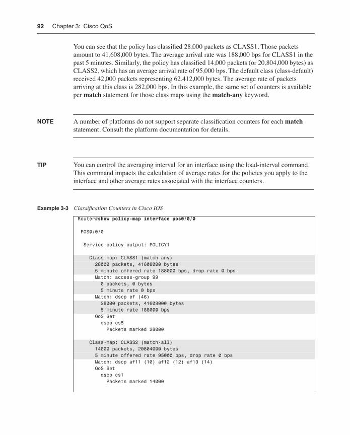
You can see that the policy has classified 28,000 packets as CLASS1. Those packets amount to 41,608,000 bytes. The average arrival rate was 188,000 bps for CLASS1 in the past 5 minutes. Similarly, the policy has classified 14,000 packets (or 20,804,000 bytes) as CLASS2, which has an average arrival rate of 95,000 bps. The default class (class-default) received 42,000 packets representing 62,412,000 bytes. The average rate of packets arriving at this class is 282,000 bps. In this example, the same set of counters is available per match statement for those class maps using the match-any keyword.
NOTE A number of platforms do not support separate classification counters for each match statement. Consult the platform documentation for details.
TIP You can control the averaging interval for an interface using the load-interval command. This command impacts the calculation of average rates for the policies you apply to the interface and other average rates associated with the interface counters.
Example 3-3 Classification Counters in Cisco IOS
Router#show policy-map interface pos0/0/0
POS0/0/0
Service-policy output: POLICY1
Class-map: CLASS1 (match-any) 28000 packets, 41608000 bytes 5 minute offered rate 188000 bps, drop rate 0 bps Match: access-group 99 0 packets, 0 bytes 5 minute rate 0 bps Match: dscp ef (46) 28000 packets, 41608000 bytes 5 minute rate 188000 bps QoS Set dscp cs5 Packets marked 28000
Class-map: CLASS2 (match-all) 14000 packets, 20804000 bytes 5 minute offered rate 95000 bps, drop rate 0 bps Match: dscp af11 (10) af12 (12) af13 (14) QoS Set dscp cs1 Packets marked 14000
Modular QoS Command-Line Interface 93
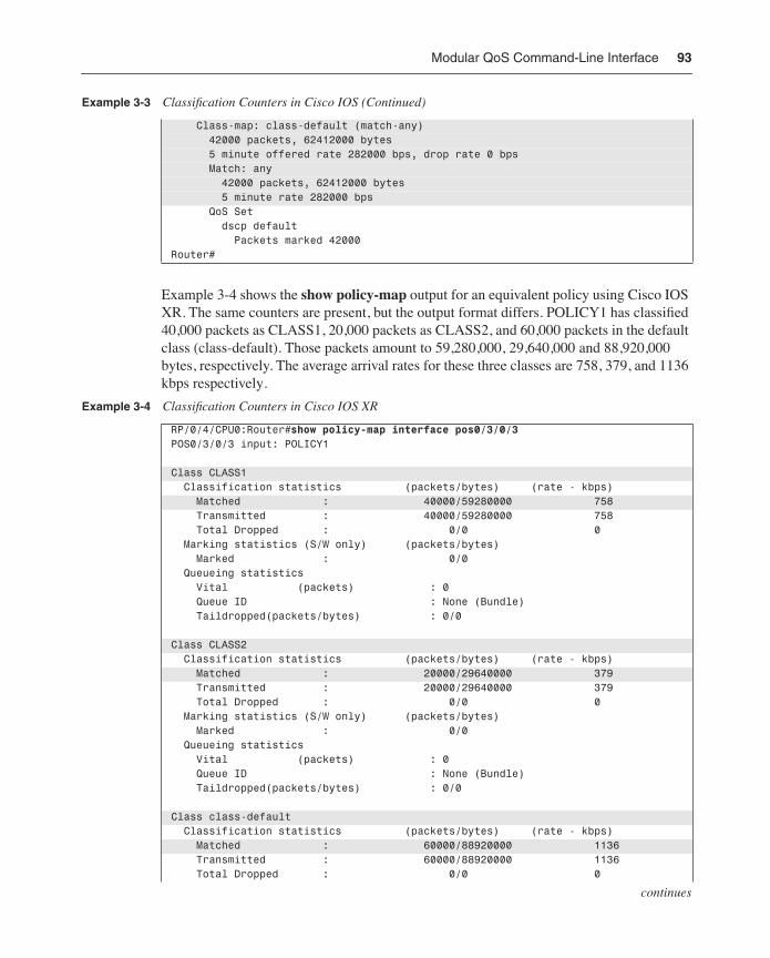
Example 3-4 shows the show policy-map output for an equivalent policy using Cisco IOS XR. The same counters are present, but the output format differs. POLICY1 has classified 40,000 packets as CLASS1, 20,000 packets as CLASS2, and 60,000 packets in the default class (class-default). Those packets amount to 59,280,000, 29,640,000 and 88,920,000 bytes, respectively. The average arrival rates for these three classes are 758, 379, and 1136 kbps respectively.
Class-map: class-default (match-any) 42000 packets, 62412000 bytes 5 minute offered rate 282000 bps, drop rate 0 bps Match: any 42000 packets, 62412000 bytes 5 minute rate 282000 bps QoS Set dscp default Packets marked 42000Router#
Example 3-4 Classification Counters in Cisco IOS XR
RP/0/4/CPU0:Router#show policy-map interface pos0/3/0/3POS0/3/0/3 input: POLICY1
Class CLASS1 Classification statistics (packets/bytes) (rate - kbps) Matched : 40000/59280000 758 Transmitted : 40000/59280000 758 Total Dropped : 0/0 0 Marking statistics (S/W only) (packets/bytes) Marked : 0/0 Queueing statistics Vital (packets) : 0 Queue ID : None (Bundle) Taildropped(packets/bytes) : 0/0
Class CLASS2 Classification statistics (packets/bytes) (rate - kbps) Matched : 20000/29640000 379 Transmitted : 20000/29640000 379 Total Dropped : 0/0 0 Marking statistics (S/W only) (packets/bytes) Marked : 0/0 Queueing statistics Vital (packets) : 0 Queue ID : None (Bundle) Taildropped(packets/bytes) : 0/0
Class class-default Classification statistics (packets/bytes) (rate - kbps) Matched : 60000/88920000 1136 Transmitted : 60000/88920000 1136 Total Dropped : 0/0 0
Example 3-3 Classification Counters in Cisco IOS (Continued)
continues
94 Chapter 3: Cisco QoS
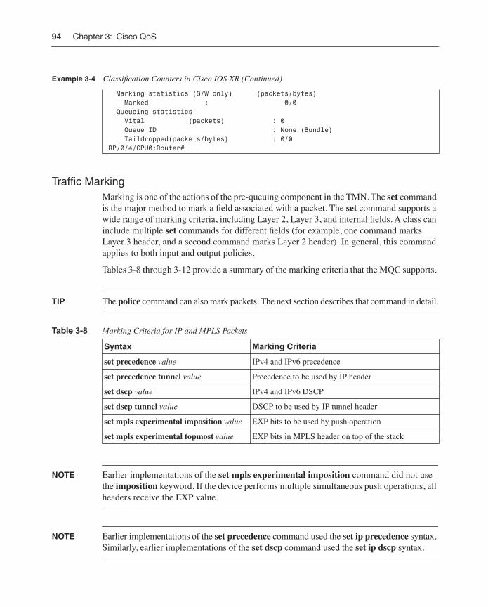
Traffic Marking Marking is one of the actions of the pre-queuing component in the TMN. The set command is the major method to mark a field associated with a packet. The set command supports a wide range of marking criteria, including Layer 2, Layer 3, and internal fields. A class can include multiple set commands for different fields (for example, one command marks Layer 3 header, and a second command marks Layer 2 header). In general, this command applies to both input and output policies.
Tables 3-8 through 3-12 provide a summary of the marking criteria that the MQC supports.
TIP The police command can also mark packets. The next section describes that command in detail.
NOTE Earlier implementations of the set mpls experimental imposition command did not use the imposition keyword. If the device performs multiple simultaneous push operations, all headers receive the EXP value.
NOTE Earlier implementations of the set precedence command used the set ip precedence syntax. Similarly, earlier implementations of the set dscp command used the set ip dscp syntax.
Marking statistics (S/W only) (packets/bytes) Marked : 0/0 Queueing statistics Vital (packets) : 0 Queue ID : None (Bundle) Taildropped(packets/bytes) : 0/0RP/0/4/CPU0:Router#
Table 3-8 Marking Criteria for IP and MPLS Packets
Syntax Marking Criteria
set precedence value IPv4 and IPv6 precedence
set precedence tunnel value Precedence to be used by IP header
set dscp value IPv4 and IPv6 DSCP
set dscp tunnel value DSCP to be used by IP tunnel header
set mpls experimental imposition value EXP bits to be used by push operation
set mpls experimental topmost value EXP bits in MPLS header on top of the stack
Example 3-4 Classification Counters in Cisco IOS XR (Continued)
Modular QoS Command-Line Interface 95
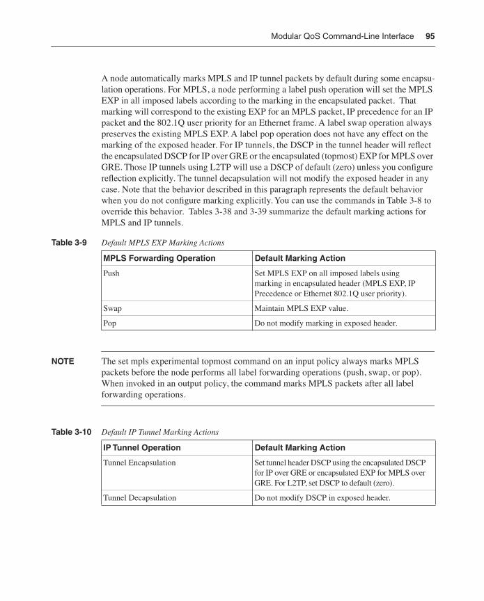
A node automatically marks MPLS and IP tunnel packets by default during some encapsu-lation operations. For MPLS, a node performing a label push operation will set the MPLS EXP in all imposed labels according to the marking in the encapsulated packet. That marking will correspond to the existing EXP for an MPLS packet, IP precedence for an IP packet and the 802.1Q user priority for an Ethernet frame. A label swap operation always preserves the existing MPLS EXP. A label pop operation does not have any effect on the marking of the exposed header. For IP tunnels, the DSCP in the tunnel header will reflect the encapsulated DSCP for IP over GRE or the encapsulated (topmost) EXP for MPLS over GRE. Those IP tunnels using L2TP will use a DSCP of default (zero) unless you configure reflection explicitly. The tunnel decapsulation will not modify the exposed header in any case. Note that the behavior described in this paragraph represents the default behavior when you do not configure marking explicitly. You can use the commands in Table 3-8 to override this behavior. Tables 3-38 and 3-39 summarize the default marking actions for MPLS and IP tunnels.
NOTE The set mpls experimental topmost command on an input policy always marks MPLS packets before the node performs all label forwarding operations (push, swap, or pop). When invoked in an output policy, the command marks MPLS packets after all label forwarding operations.
Table 3-9 Default MPLS EXP Marking Actions
MPLS Forwarding Operation Default Marking Action
Push Set MPLS EXP on all imposed labels using marking in encapsulated header (MPLS EXP, IP Precedence or Ethernet 802.1Q user priority).
Swap Maintain MPLS EXP value.
Pop Do not modify marking in exposed header.
Table 3-10 Default IP Tunnel Marking Actions
IP Tunnel Operation Default Marking Action
Tunnel Encapsulation Set tunnel header DSCP using the encapsulated DSCP for IP over GRE or encapsulated EXP for MPLS over GRE. For L2TP, set DSCP to default (zero).
Tunnel Decapsulation Do not modify DSCP in exposed header.
96 Chapter 3: Cisco QoS
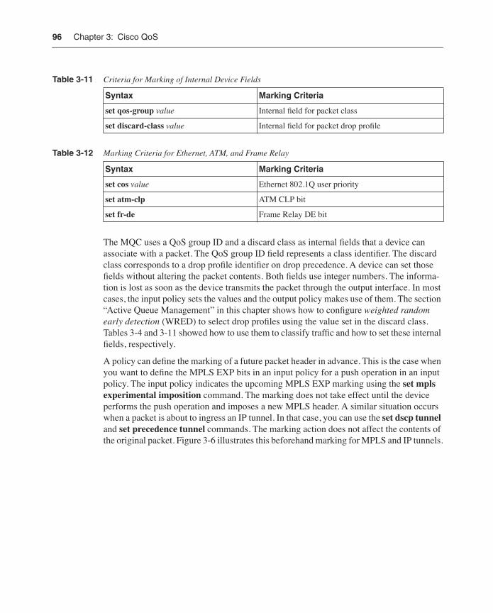
The MQC uses a QoS group ID and a discard class as internal fields that a device can associate with a packet. The QoS group ID field represents a class identifier. The discard class corresponds to a drop profile identifier on drop precedence. A device can set those fields without altering the packet contents. Both fields use integer numbers. The informa-tion is lost as soon as the device transmits the packet through the output interface. In most cases, the input policy sets the values and the output policy makes use of them. The section “Active Queue Management” in this chapter shows how to configure weighted random early detection (WRED) to select drop profiles using the value set in the discard class. Tables 3-4 and 3-11 showed how to use them to classify traffic and how to set these internal fields, respectively.
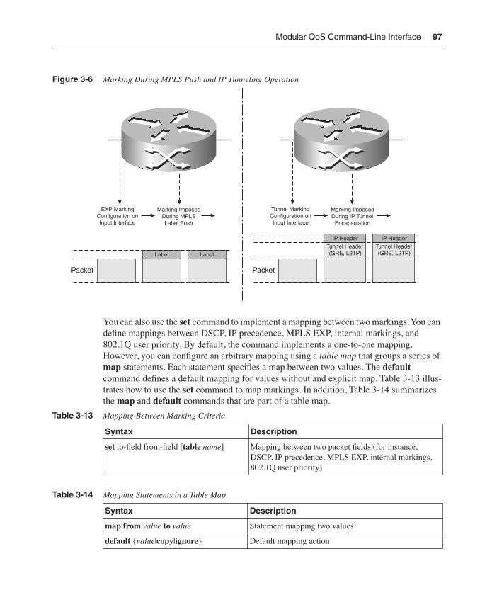
A policy can define the marking of a future packet header in advance. This is the case when you want to define the MPLS EXP bits in an input policy for a push operation in an input policy. The input policy indicates the upcoming MPLS EXP marking using the set mpls experimental imposition command. The marking does not take effect until the device performs the push operation and imposes a new MPLS header. A similar situation occurs when a packet is about to ingress an IP tunnel. In that case, you can use the set dscp tunnel and set precedence tunnel commands. The marking action does not affect the contents of the original packet. Figure 3-6 illustrates this beforehand marking for MPLS and IP tunnels.
Table 3-11 Criteria for Marking of Internal Device Fields
Syntax Marking Criteria
set qos-group value Internal field for packet class
set discard-class value Internal field for packet drop profile
Table 3-12 Marking Criteria for Ethernet, ATM, and Frame Relay
Syntax Marking Criteria
set cos value Ethernet 802.1Q user priority
set atm-clp ATM CLP bit
set fr-de Frame Relay DE bit
Modular QoS Command-Line Interface 97
Figure 3-6 Marking During MPLS Push and IP Tunneling Operation
You can also use the set command to implement a mapping between two markings. You can define mappings between DSCP, IP precedence, MPLS EXP, internal markings, and 802.1Q user priority. By default, the command implements a one-to-one mapping. However, you can configure an arbitrary mapping using a table map that groups a series of map statements. Each statement specifies a map between two values. The default command defines a default mapping for values without and explicit map. Table 3-13 illus-trates how to use the set command to map markings. In addition, Table 3-14 summarizes the map and default commands that are part of a table map.
Table 3-13 Mapping Between Marking Criteria
Syntax Description
set to-field from-field [table name] Mapping between two packet fields (for instance, DSCP, IP precedence, MPLS EXP, internal markings, 802.1Q user priority)
Table 3-14 Mapping Statements in a Table Map
Syntax Description
map from value to value Statement mapping two values
default {value|copy|ignore} Default mapping action
Tunnel Header(GRE, L2TP)
Packet
Marking ImposedDuring IP Tunnel
Encapsulation
Tunnel MarkingConfiguration onInput Interface
IP HeaderTunnel Header(GRE, L2TP)
IP Header
Marking ImposedDuring MPLSLabel Push
EXP MarkingConfiguration onInput Interface
Packet
Label Label
98 Chapter 3: Cisco QoS
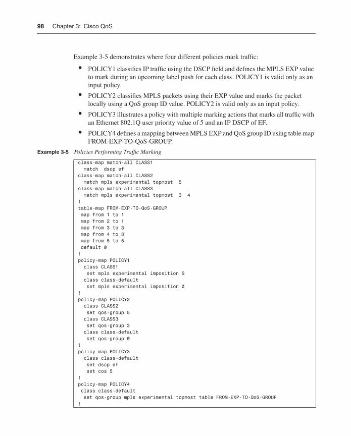
Example 3-5 demonstrates where four different policies mark traffic:
• POLICY1 classifies IP traffic using the DSCP field and defines the MPLS EXP value to mark during an upcoming label push for each class. POLICY1 is valid only as an input policy.
• POLICY2 classifies MPLS packets using their EXP value and marks the packet locally using a QoS group ID value. POLICY2 is valid only as an input policy.
• POLICY3 illustrates a policy with multiple marking actions that marks all traffic with an Ethernet 802.1Q user priority value of 5 and an IP DSCP of EF.
• POLICY4 defines a mapping between MPLS EXP and QoS group ID using table map FROM-EXP-TO-QoS-GROUP.
Example 3-5 Policies Performing Traffic Marking
class-map match-all CLASS1 match dscp ef class-map match-all CLASS2 match mpls experimental topmost 5 class-map match-all CLASS3 match mpls experimental topmost 3 4 !table-map FROM-EXP-TO-QoS-GROUP map from 1 to 1 map from 2 to 1 map from 3 to 3 map from 4 to 3 map from 5 to 5 default 0!policy-map POLICY1 class CLASS1 set mpls experimental imposition 5 class class-default set mpls experimental imposition 0!policy-map POLICY2 class CLASS2 set qos-group 5 class CLASS3 set qos-group 3 class class-default set qos-group 0!policy-map POLICY3 class class-default set dscp ef set cos 5! policy-map POLICY4 class class-default set qos-group mpls experimental topmost table FROM-EXP-TO-QoS-GROUP!
Modular QoS Command-Line Interface 99
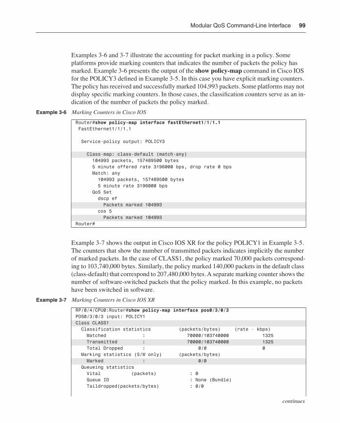
Examples 3-6 and 3-7 illustrate the accounting for packet marking in a policy. Some platforms provide marking counters that indicates the number of packets the policy has marked. Example 3-6 presents the output of the show policy-map command in Cisco IOS for the POLICY3 defined in Example 3-5. In this case you have explicit marking counters. The policy has received and successfully marked 104,993 packets. Some platforms may not display specific marking counters. In those cases, the classification counters serve as an in-dication of the number of packets the policy marked.
Example 3-7 shows the output in Cisco IOS XR for the policy POLICY1 in Example 3-5. The counters that show the number of transmitted packets indicates implicitly the number of marked packets. In the case of CLASS1, the policy marked 70,000 packets correspond-ing to 103,740,000 bytes. Similarly, the policy marked 140,000 packets in the default class (class-default) that correspond to 207,480,000 bytes. A separate marking counter shows the number of software-switched packets that the policy marked. In this example, no packets have been switched in software.
Example 3-6 Marking Counters in Cisco IOS
Router#show policy-map interface fastEthernet1/1/1.1 FastEthernet1/1/1.1
Service-policy output: POLICY3
Class-map: class-default (match-any) 104993 packets, 157489500 bytes 5 minute offered rate 3196000 bps, drop rate 0 bps Match: any 104993 packets, 157489500 bytes 5 minute rate 3196000 bps QoS Set dscp ef Packets marked 104993 cos 5 Packets marked 104993Router#
Example 3-7 Marking Counters in Cisco IOS XR
RP/0/4/CPU0:Router#show policy-map interface pos0/3/0/3POS0/3/0/3 input: POLICY1Class CLASS1 Classification statistics (packets/bytes) (rate - kbps) Matched : 70000/103740000 1325 Transmitted : 70000/103740000 1325 Total Dropped : 0/0 0 Marking statistics (S/W only) (packets/bytes) Marked : 0/0 Queueing statistics Vital (packets) : 0 Queue ID : None (Bundle) Taildropped(packets/bytes) : 0/0
continues
100 Chapter 3: Cisco QoS
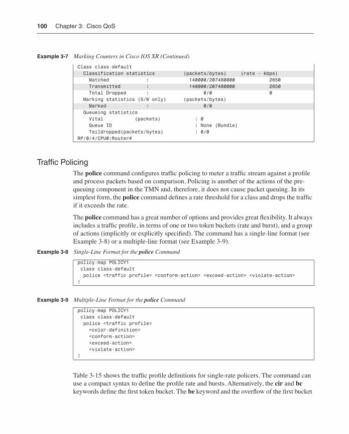
Traffic PolicingThe police command configures traffic policing to meter a traffic stream against a profile and process packets based on comparison. Policing is another of the actions of the pre-queuing component in the TMN and, therefore, it does not cause packet queuing. In its simplest form, the police command defines a rate threshold for a class and drops the traffic if it exceeds the rate.
The police command has a great number of options and provides great flexibility. It always includes a traffic profile, in terms of one or two token buckets (rate and burst), and a group of actions (implicitly or explicitly specified). The command has a single-line format (see Example 3-8) or a multiple-line format (see Example 3-9).
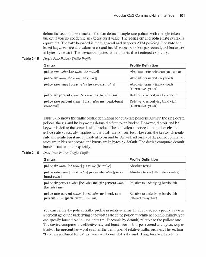
Table 3-15 shows the traffic profile definitions for single-rate policers. The command can use a compact syntax to define the profile rate and bursts. Alternatively, the cir and bc keywords define the first token bucket. The be keyword and the overflow of the first bucket
Class class-default Classification statistics (packets/bytes) (rate - kbps) Matched : 140000/207480000 2650 Transmitted : 140000/207480000 2650 Total Dropped : 0/0 0 Marking statistics (S/W only) (packets/bytes) Marked : 0/0 Queueing statistics Vital (packets) : 0 Queue ID : None (Bundle) Taildropped(packets/bytes) : 0/0RP/0/4/CPU0:Router#
Example 3-8 Single-Line Format for the police Command
policy-map POLICY1 class class-default police <traffic profile> <conform-action> <exceed-action> <violate-action>!
Example 3-9 Multiple-Line Format for the police Command
policy-map POLICY1 class class-default police <traffic profile> <color-definition> <conform-action> <exceed-action> <violate-action>!
Example 3-7 Marking Counters in Cisco IOS XR (Continued)
Modular QoS Command-Line Interface 101
define the second token bucket. You can define a single-rate policer with a single token bucket if you do not define an excess burst value. The police cir and police rate syntax is equivalent. The rate keyword is more general and supports ATM policing. The rate and burst keywords are equivalent to cir and bc. All rates are in bits per second, and bursts are in bytes by default. The device computes default bursts if not entered explicitly.
Table 3-16 shows the traffic profile definitions for dual-rate policers. As with the single-rate policer, the cir and bc keywords define the first token bucket. However, the pir and be keywords define the second token bucket. The equivalence between the police cir and police rate syntax also applies to the dual-rate policer, too. However, the keywords peak-rate and peak-burst are equivalent to pir and be. As with all forms of the police command, rates are in bits per second and bursts are in bytes by default. The device computes default bursts if not entered explicitly.
You can define the policer traffic profile in relative terms. In this case, you specify a rate as a percentage of the underlying bandwidth rate of the policy attachment point. Similarly, you can specify burst sizes in time units (milliseconds by default) relative to the policer rate. The device computes the effective rate and burst sizes in bits per second and bytes, respec-tively. The percent keyword enables the definition of relative traffic profiles. The section “Percentage-Based Rates” explains what constitutes the underlying bandwidth rate that
Table 3-15 Single-Rate Policer Traffic Profile
Syntax Profile Definition
police rate-value [bc-value [be-value]] Absolute terms with compact syntax
police cir value [bc value [be value]] Absolute terms with keywords
police rate value [burst value [peak-burst value]] Absolute terms with keywords (alternative syntax)
police cir percent value [bc value ms [be value ms]] Relative to underlying bandwidth
police rate percent value [burst value ms [peak-burst value ms]]
Relative to underlying bandwidth (alternative syntax)
Table 3-16 Dual-Rate Policer Traffic Profile
Syntax Profile Definition
police cir value [bc value] pir value [be value] Absolute terms
police rate value [burst value] peak-rate value [peak-burst value]
Absolute terms (alternative syntax)
police cir percent value [bc value ms] pir percent value [be value ms]
Relative to underlying bandwidth
police rate percent value [burst value ms] peak-rate percent value [peak-burst value ms]
Relative to underlying bandwidth (alternative syntax)
102 Chapter 3: Cisco QoS
nodes use to interpret relative profile definitions. In its simplest form, the underlying bandwidth rate for a policy that you attach to a physical interface corresponds to the interface bandwidth rate.
TIP The police percent command helps reuse policies across interfaces of different speeds. The reuse of policies has significant operational benefits on devices with a large number of interfaces.
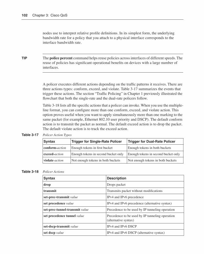
A policer executes different actions depending on the traffic patterns it receives. There are three actions types: conform, exceed, and violate. Table 3-17 summarizes the events that trigger these actions. The section “Traffic Policing” in Chapter 1 previously illustrated the flowchart that both the single-rate and the dual-rate policers follow.
Table 3-18 lists all the specific actions that a policer can invoke. When you use the multiple-line format, you can configure more than one conform, exceed, and violate action. This option proves useful when you want to apply simultaneously more than one marking to the same packet (for example, Ethernet 802.10 user priority and DSCP). The default conform action is to transmit the packet as normal. The default exceed action is to drop the packet. The default violate action is to track the exceed action.
Table 3-17 Policer Action Types
Syntax Trigger for Single-Rate Policer Trigger for Dual-Rate Policer
conform-action Enough tokens in first bucket Enough tokens in both buckets
exceed-action Enough tokens in second bucket only Enough tokens in second bucket only
violate-action Not enough tokens in both buckets Not enough tokens in both buckets
Table 3-18 Policer Actions
Syntax Description
drop Drops packet
transmit Transmits packet without modifications
set-prec-transmit value IPv4 and IPv6 precedence
set precedence value IPv4 and IPv6 precedence (alternative syntax)
set-prec-tunnel-transmit value Precedence to be used by IP tunneling operation
set precedence tunnel value Precedence to be used by IP tunneling operation (alternative syntax)
set-dscp-transmit value IPv4 and IPv6 DSCP
set dscp value IPv4 and IPv6 DSCP (alternative syntax)
Modular QoS Command-Line Interface 103
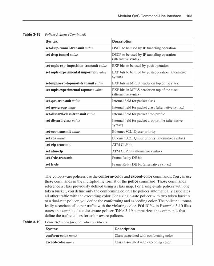
The color-aware policers use the conform-color and exceed-color commands. You can use these commands in the multiple-line format of the police command. Those commands reference a class previously defined using a class map. For a single-rate policer with one token bucket, you define only the conforming color. The policer automatically associates all other traffic with the exceeding color. For a single-rate policer with two token buckets or a dual-rate policer, you define the conforming and exceeding color. The policer automat-ically associates all other traffic with the violating color. POLICY4 in Example 3-10 illus-trates an example of a color-aware policer. Table 3-19 summarizes the commands that define the traffic colors for color-aware policers.
Syntax Description
set-dscp-tunnel-transmit value DSCP to be used by IP tunneling operation
set dscp tunnel value DSCP to be used by IP tunneling operation (alternative syntax)
set-mpls-exp-imposition-transmit value EXP bits to be used by push operation
set mpls experimental imposition value EXP bits to be used by push operation (alternative syntax)
set-mpls-exp-topmost-transmit value EXP bits in MPLS header on top of the stack
set mpls experimental topmost value EXP bits in MPLS header on top of the stack (alternative syntax)
set-qos-transmit value Internal field for packet class
set qos-group value Internal field for packet class (alternative syntax)
set-discard-class-transmit value Internal field for packet drop profile
set discard-class value Internal field for packet drop profile (alternative syntax)
set-cos-transmit value Ethernet 802.1Q user priority
set cos value Ethernet 802.1Q user priority (alternative syntax)
set-clp-transmit ATM CLP bit
set atm-clp ATM CLP bit (alternative syntax)
set-frde-transmit Frame Relay DE bit
set fr-de Frame Relay DE bit (alternative syntax)
Table 3-19 Color Definition for Color-Aware Policers
Syntax Description
conform-color name Class associated with conforming color
exceed-color name Class associated with exceeding color
Table 3-18 Policer Actions (Continued)
104 Chapter 3: Cisco QoS
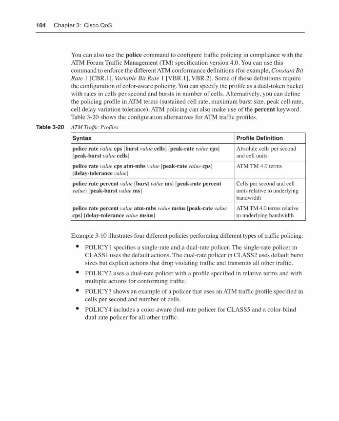
You can also use the police command to configure traffic policing in compliance with the ATM Forum Traffic Management (TM) specification version 4.0. You can use this command to enforce the different ATM conformance definitions (for example, Constant Bit Rate 1 [CBR.1], Variable Bit Rate 1 [VBR.1], VBR.2). Some of those definitions require the configuration of color-aware policing. You can specify the profile as a dual-token bucket with rates in cells per second and bursts in number of cells. Alternatively, you can define the policing profile in ATM terms (sustained cell rate, maximum burst size, peak cell rate, cell delay variation tolerance). ATM policing can also make use of the percent keyword. Table 3-20 shows the configuration alternatives for ATM traffic profiles.
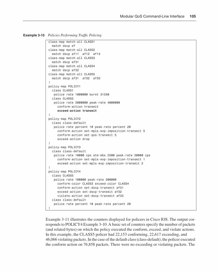
Example 3-10 illustrates four different policies performing different types of traffic policing:
• POLICY1 specifies a single-rate and a dual-rate policer. The single-rate policer in CLASS1 uses the default actions. The dual-rate policer in CLASS2 uses default burst sizes but explicit actions that drop violating traffic and transmits all other traffic.
• POLICY2 uses a dual-rate policer with a profile specified in relative terms and with multiple actions for conforming traffic.
• POLICY3 shows an example of a policer that uses an ATM traffic profile specified in cells per second and number of cells.
• POLICY4 includes a color-aware dual-rate policer for CLASS5 and a color-blind dual-rate policer for all other traffic.
Table 3-20 ATM Traffic Profiles
Syntax Profile Definition
police rate value cps [burst value cells] [peak-rate value cps] [peak-burst value cells]
Absolute cells per second and cell units
police rate value cps atm-mbs value [peak-rate value cps] [delay-tolerance value]
ATM TM 4.0 terms
police rate percent value [burst value ms] [peak-rate percent value] [peak-burst value ms]
Cells per second and cell units relative to underlying bandwidth
police rate percent value atm-mbs value ms|us [peak-rate value cps] [delay-tolerance value ms|us]
ATM TM 4.0 terms relative to underlying bandwidth
Modular QoS Command-Line Interface 105
Example 3-11 illustrates the counters displayed for policers in Cisco IOS. The output cor-responds to POLICY4 Example 3-10. A basic set of counters specify the number of packets (and related bytes) on which the policy executed the conform, exceed, and violate actions. In this example, the CLASS5 policer had 22,153 conforming, 22,617 exceeding, and 46,066 violating packets. In the case of the default class (class-default), the policer executed the conform action on 76,858 packets. There were no exceeding or violating packets. The
Example 3-10 Policies Performing Traffic Policing
class-map match-all CLASS1 match dscp ef class-map match-all CLASS2 match dscp af11 af12 af13 class-map match-all CLASS3 match dscp af31 class-map match-all CLASS4 match dscp af32 class-map match-all CLASS5 match dscp af31 af32 af33!policy-map POLICY1 class CLASS1 police rate 1000000 burst 31250 class CLASS2 police rate 2000000 peak-rate 4000000 conform-action transmit exceed-action transmit !policy-map POLICY2 class class-default police rate percent 10 peak-rate percent 20 conform-action set-mpls-exp-imposition-transmit 5 conform-action set-qos-transmit 5 exceed-action drop !policy-map POLICY3 class class-default police rate 10000 cps atm-mbs 2500 peak-rate 20000 cps conform-action set-mpls-exp-imposition-transmit 1 exceed-action set-mpls-exp-imposition-transmit 2!policy-map POLICY4 class CLASS5 police rate 100000 peak-rate 200000 conform-color CLASS3 exceed-color CLASS4 conform-action set-dscp-transmit af31 exceed-action set-dscp-transmit af32 violate-action set-dscp-transmit af33 class class-default police rate percent 10 peak-rate percent 20!
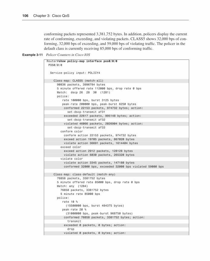
106 Chapter 3: Cisco QoS
conforming packets represented 3,381,752 bytes. In addition, policers display the current rate of conforming, exceeding, and violating packets. CLASS5 shows 32,000 bps of con-forming, 32,000 bps of exceeding, and 59,000 bps of violating traffic. The policer in the default class is currently receiving 85,000 bps of conforming traffic.
Example 3-11 Policer Counters in Cisco IOS
Router#show policy-map interface pos0/0/0 POS0/0/0
Service-policy input: POLICY4
Class-map: CLASS5 (match-all) 90836 packets, 3996784 bytes 5 minute offered rate 112000 bps, drop rate 0 bps Match: dscp 26 28 30 (1281) police: rate 100000 bps, burst 3125 bytes peak-rate 200000 bps, peak-burst 6250 bytes conformed 22153 packets, 974732 bytes; action: set-dscp-transmit af31 exceeded 22617 packets, 995148 bytes; action: set-dscp-transmit af32 violated 46066 packets, 2026904 bytes; action: set-dscp-transmit af33 conform color conform action 22153 packets, 974732 bytes exceed action 19705 packets, 867020 bytes violate action 36691 packets, 1614404 bytes exceed color exceed action 2912 packets, 128128 bytes violate action 6030 packets, 265320 bytes violate color violate action 3345 packets, 147180 bytes conformed 32000 bps, exceeded 32000 bps violated 59000 bps
Class-map: class-default (match-any) 76858 packets, 3381752 bytes 5 minute offered rate 85000 bps, drop rate 0 bps Match: any (1284) 76858 packets, 3381752 bytes 5 minute rate 85000 bps police: rate 10 % (15500000 bps, burst 484375 bytes) peak-rate 20 % (31000000 bps, peak-burst 968750 bytes) conformed 76858 packets, 3381752 bytes; action: transmit exceeded 0 packets, 0 bytes; action: drop violated 0 packets, 0 bytes; action:
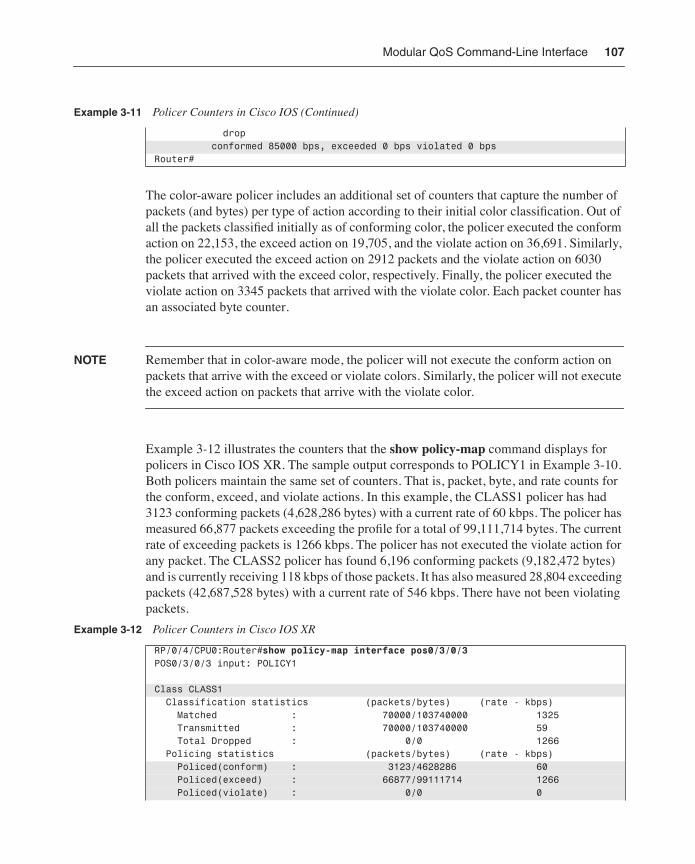
Modular QoS Command-Line Interface 107
The color-aware policer includes an additional set of counters that capture the number of packets (and bytes) per type of action according to their initial color classification. Out of all the packets classified initially as of conforming color, the policer executed the conform action on 22,153, the exceed action on 19,705, and the violate action on 36,691. Similarly, the policer executed the exceed action on 2912 packets and the violate action on 6030 packets that arrived with the exceed color, respectively. Finally, the policer executed the violate action on 3345 packets that arrived with the violate color. Each packet counter has an associated byte counter.
NOTE Remember that in color-aware mode, the policer will not execute the conform action on packets that arrive with the exceed or violate colors. Similarly, the policer will not execute the exceed action on packets that arrive with the violate color.
Example 3-12 illustrates the counters that the show policy-map command displays for policers in Cisco IOS XR. The sample output corresponds to POLICY1 in Example 3-10. Both policers maintain the same set of counters. That is, packet, byte, and rate counts for the conform, exceed, and violate actions. In this example, the CLASS1 policer has had 3123 conforming packets (4,628,286 bytes) with a current rate of 60 kbps. The policer has measured 66,877 packets exceeding the profile for a total of 99,111,714 bytes. The current rate of exceeding packets is 1266 kbps. The policer has not executed the violate action for any packet. The CLASS2 policer has found 6,196 conforming packets (9,182,472 bytes) and is currently receiving 118 kbps of those packets. It has also measured 28,804 exceeding packets (42,687,528 bytes) with a current rate of 546 kbps. There have not been violating packets.
drop conformed 85000 bps, exceeded 0 bps violated 0 bpsRouter#
Example 3-12 Policer Counters in Cisco IOS XR
RP/0/4/CPU0:Router#show policy-map interface pos0/3/0/3POS0/3/0/3 input: POLICY1
Class CLASS1 Classification statistics (packets/bytes) (rate - kbps) Matched : 70000/103740000 1325 Transmitted : 70000/103740000 59 Total Dropped : 0/0 1266 Policing statistics (packets/bytes) (rate - kbps) Policed(conform) : 3123/4628286 60 Policed(exceed) : 66877/99111714 1266 Policed(violate) : 0/0 0
Example 3-11 Policer Counters in Cisco IOS (Continued)
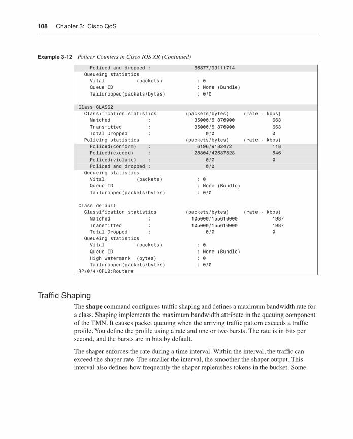
108 Chapter 3: Cisco QoS
Traffic ShapingThe shape command configures traffic shaping and defines a maximum bandwidth rate for a class. Shaping implements the maximum bandwidth attribute in the queuing component of the TMN. It causes packet queuing when the arriving traffic pattern exceeds a traffic profile. You define the profile using a rate and one or two bursts. The rate is in bits per second, and the bursts are in bits by default.
The shaper enforces the rate during a time interval. Within the interval, the traffic can exceed the shaper rate. The smaller the interval, the smoother the shaper output. This interval also defines how frequently the shaper replenishes tokens in the bucket. Some
Policed and dropped : 66877/99111714 Queueing statistics Vital (packets) : 0 Queue ID : None (Bundle) Taildropped(packets/bytes) : 0/0
Class CLASS2 Classification statistics (packets/bytes) (rate - kbps) Matched : 35000/51870000 663 Transmitted : 35000/51870000 663 Total Dropped : 0/0 0 Policing statistics (packets/bytes) (rate - kbps) Policed(conform) : 6196/9182472 118 Policed(exceed) : 28804/42687528 546 Policed(violate) : 0/0 0 Policed and dropped : 0/0 Queueing statistics Vital (packets) : 0 Queue ID : None (Bundle) Taildropped(packets/bytes) : 0/0
Class default Classification statistics (packets/bytes) (rate - kbps) Matched : 105000/155610000 1987 Transmitted : 105000/155610000 1987 Total Dropped : 0/0 0 Queueing statistics Vital (packets) : 0 Queue ID : None (Bundle) High watermark (bytes) : 0 Taildropped(packets/bytes) : 0/0RP/0/4/CPU0:Router#
Example 3-12 Policer Counters in Cisco IOS XR (Continued)
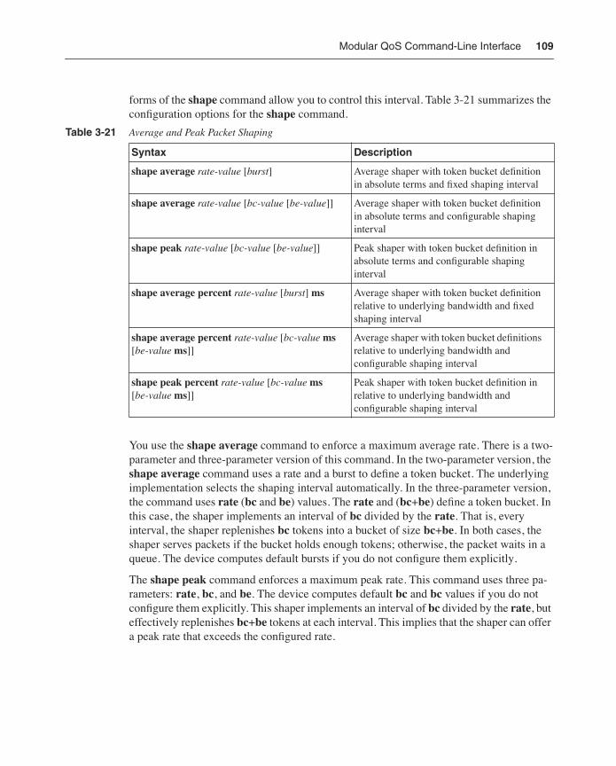
Modular QoS Command-Line Interface 109
forms of the shape command allow you to control this interval. Table 3-21 summarizes the configuration options for the shape command.
You use the shape average command to enforce a maximum average rate. There is a two-parameter and three-parameter version of this command. In the two-parameter version, the shape average command uses a rate and a burst to define a token bucket. The underlying implementation selects the shaping interval automatically. In the three-parameter version, the command uses rate (bc and be) values. The rate and (bc+be) define a token bucket. In this case, the shaper implements an interval of bc divided by the rate. That is, every interval, the shaper replenishes bc tokens into a bucket of size bc+be. In both cases, the shaper serves packets if the bucket holds enough tokens; otherwise, the packet waits in a queue. The device computes default bursts if you do not configure them explicitly.
The shape peak command enforces a maximum peak rate. This command uses three pa-rameters: rate, bc, and be. The device computes default bc and bc values if you do not configure them explicitly. This shaper implements an interval of bc divided by the rate, but effectively replenishes bc+be tokens at each interval. This implies that the shaper can offer a peak rate that exceeds the configured rate.
Table 3-21 Average and Peak Packet Shaping
Syntax Description
shape average rate-value [burst] Average shaper with token bucket definition in absolute terms and fixed shaping interval
shape average rate-value [bc-value [be-value]] Average shaper with token bucket definition in absolute terms and configurable shaping interval
shape peak rate-value [bc-value [be-value]] Peak shaper with token bucket definition in absolute terms and configurable shaping interval
shape average percent rate-value [burst] ms Average shaper with token bucket definition relative to underlying bandwidth and fixed shaping interval
shape average percent rate-value [bc-value ms [be-value ms]]
Average shaper with token bucket definitions relative to underlying bandwidth and configurable shaping interval
shape peak percent rate-value [bc-value ms [be-value ms]]
Peak shaper with token bucket definition in relative to underlying bandwidth and configurable shaping interval
110 Chapter 3: Cisco QoS
You control the peak rate with the value of be. This shaping behavior is useful for Frame Relay environments making use of a committed information rate (CIR), an excess informa-tion rate (EIR), and a peak information rate (PIR). In this case, the shape rate equals the CIR. If tc is the shaper interval, the following relationships hold:
tc = bc / CIR PIR = (bc + be) / tcPIR = CIR + CIR (be / bc)PIR = CIR + EIREIR = CIR (be / bc)
You can also define the shaping parameters in relative terms. In this case, you specify the shaper rate as a percentage of the underlying bandwidth rate of the policy attachment point. Similarly, you specify the burst, bc, and be values in time units (milliseconds by default) relative to the shaper rate. The device computes the effective parameters in absolute values. The percent keyword enables the definition of relative traffic profiles. Both the shape average and shape peak commands support this keyword. The section “Percentage-Based Rates” explains what constitutes the underlying bandwidth rate that the device uses to interpret relative profile definitions.
Figure 3-7 shows the output of three sample shapers for a given packet-arrival pattern. Each black box represents a packet, and each gray box represents a token. A stream of packets arrives at an average rate of 200 packets per second (pps). In this example, all parameters are normalized in packets and packets have the same size. These assumptions will help you understand the operation of the shapers, which in reality operate in bits and bits per second. The first configuration (from top to bottom) uses a two-parameter average shaper. This par-ticular shaper implementation uses a 5-ms shaping interval (one token every 5 ms). The second configuration uses a three-parameter average shaper. The last configuration uses peak shaping. Notice how the first shaper smoothes traffic the most, and the last one has the least smoothing effect. These are the sequence of events for the two-parameter average shaper:
• Initial state—Bucket holds two tokens.
• (0 ms, 5 ms)—Three packets arrive. Two tokens are consumed and one packet is queued. Bucket becomes empty.
• (5 ms, 10 ms)—One token accumulates and is used to serve the queued packet. No new packets arrive. Bucket becomes empty.
• (10 ms, 15 ms)—One token accumulates. No new packets arrive. Bucket holds one token.
• (15 ms, 20 ms)—One token accumulates. No new packets arrive. Bucket holds two tokens.
Modular QoS Command-Line Interface 111
• (20 ms, 25 ms)—Additional token discarded because bucket is full. One packet arrives and consumes one token. Bucket holds one token.
• (25 ms, 30 ms)—One token accumulates. No new packet arrives. Bucket holds two tokens.
• (30 ms, 35 ms)—Additional token discarded because bucket is full. One packet arrives and consumes one token. Bucket holds one token.
• (35 ms, 40 ms)—One token accumulates. One packet arrives and consumes one token. Bucket holds one token.
• (40 ms, 45 ms)—One token accumulates. Four packets arrive and consume two tokens. Two packets are queued. Bucket becomes empty.
• (45 ms, 50 ms)—One token accumulates and is used to serve one queued packet. Four packets arrive. Five packets are queued. Bucket becomes empty.
• (50 ms, 55 ms)—One token accumulates and is used to serve one queued packet. No new packets arrive. Four packets are queued. Bucket becomes empty.
• (55 ms, 60 ms)—One token accumulates and is used to serve one queued packet. No new packets arrive. Three packets are queued. Bucket becomes empty.
• (60 ms, 65 ms)—One token accumulates and is used to serve one queued packet. No new packets arrive. Two packets are queued. Bucket becomes empty.
• (65 ms, 70 ms)—One token accumulates and is used to serve one queued packet. No new packets arrive. One packet is queued. Bucket becomes empty.
• (70 ms, 75 ms)—One token accumulates and is used to serve one queued packet. No new packets arrive. No packets are queued. Bucket becomes empty.
The shape adaptive command adjusts the shaper rate in response to congestion notifica-tion. This command defines a reduced shaping rate. Adaptive shaping is useful for a Frame Relay environment where a device learns about network congestion from frames that arrive with the backward explicit congestion notification (BECN) flag set. When a device receives a congestion notification, the shaper decreases the shaping rate until it reaches the config-ured reduced rate. When the arrival of congestion notifications ceases, the shaper increases the shaping rate back to the original maximum rate. You can configure adaptive shaping with either the average or the peak shaping discussed earlier. Table 3-22 summarizes the shape adaptive command.
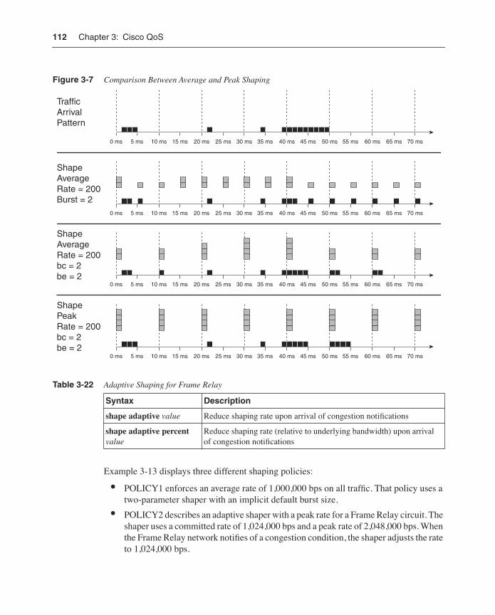
112 Chapter 3: Cisco QoS
Figure 3-7 Comparison Between Average and Peak Shaping
Example 3-13 displays three different shaping policies:
• POLICY1 enforces an average rate of 1,000,000 bps on all traffic. That policy uses a two-parameter shaper with an implicit default burst size.
• POLICY2 describes an adaptive shaper with a peak rate for a Frame Relay circuit. The shaper uses a committed rate of 1,024,000 bps and a peak rate of 2,048,000 bps. When the Frame Relay network notifies of a congestion condition, the shaper adjusts the rate to 1,024,000 bps.
Table 3-22 Adaptive Shaping for Frame Relay
Syntax Description
shape adaptive value Reduce shaping rate upon arrival of congestion notifications
shape adaptive percent value
Reduce shaping rate (relative to underlying bandwidth) upon arrival of congestion notifications
TrafficArrivalPattern
0 ms 10 ms 20 ms 30 ms 40 ms 50 ms 60 ms 70 ms5 ms 15 ms 25 ms 35 ms 45 ms 55 ms 65 ms
0 ms 10 ms 20 ms 30 ms 40 ms 50 ms 60 ms 70 ms5 ms 15 ms 25 ms 35 ms 45 ms 55 ms 65 ms
0 ms 10 ms 20 ms 30 ms 40 ms 50 ms 60 ms 70 ms5 ms 15 ms 25 ms 35 ms 45 ms 55 ms 65 ms
0 ms 10 ms 20 ms 30 ms 40 ms 50 ms 60 ms 70 ms5 ms 15 ms 25 ms 35 ms 45 ms 55 ms 65 ms
ShapeAverageRate = 200Burst = 2
ShapeAverageRate = 200bc = 2be = 2
ShapePeakRate = 200bc = 2be = 2
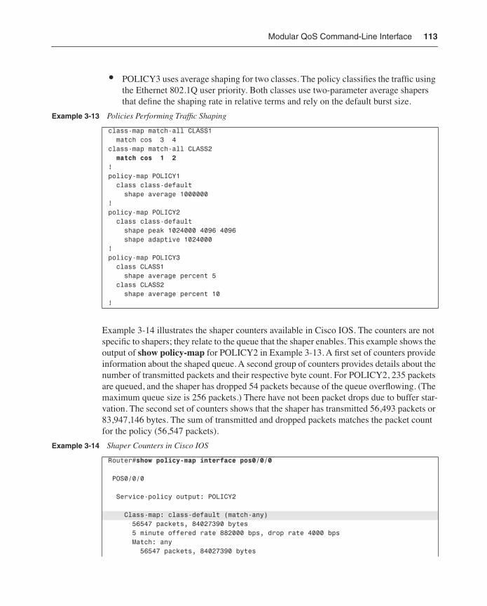
Modular QoS Command-Line Interface 113
• POLICY3 uses average shaping for two classes. The policy classifies the traffic using the Ethernet 802.1Q user priority. Both classes use two-parameter average shapers that define the shaping rate in relative terms and rely on the default burst size.
Example 3-14 illustrates the shaper counters available in Cisco IOS. The counters are not specific to shapers; they relate to the queue that the shaper enables. This example shows the output of show policy-map for POLICY2 in Example 3-13. A first set of counters provide information about the shaped queue. A second group of counters provides details about the number of transmitted packets and their respective byte count. For POLICY2, 235 packets are queued, and the shaper has dropped 54 packets because of the queue overflowing. (The maximum queue size is 256 packets.) There have not been packet drops due to buffer star-vation. The second set of counters shows that the shaper has transmitted 56,493 packets or 83,947,146 bytes. The sum of transmitted and dropped packets matches the packet count for the policy (56,547 packets).
Example 3-13 Policies Performing Traffic Shaping
class-map match-all CLASS1 match cos 3 4 class-map match-all CLASS2 match cos 1 2 !policy-map POLICY1 class class-default shape average 1000000!policy-map POLICY2 class class-default shape peak 1024000 4096 4096 shape adaptive 1024000!policy-map POLICY3 class CLASS1 shape average percent 5 class CLASS2 shape average percent 10!
Example 3-14 Shaper Counters in Cisco IOS
Router#show policy-map interface pos0/0/0
POS0/0/0
Service-policy output: POLICY2
Class-map: class-default (match-any) 56547 packets, 84027390 bytes 5 minute offered rate 882000 bps, drop rate 4000 bps Match: any 56547 packets, 84027390 bytes
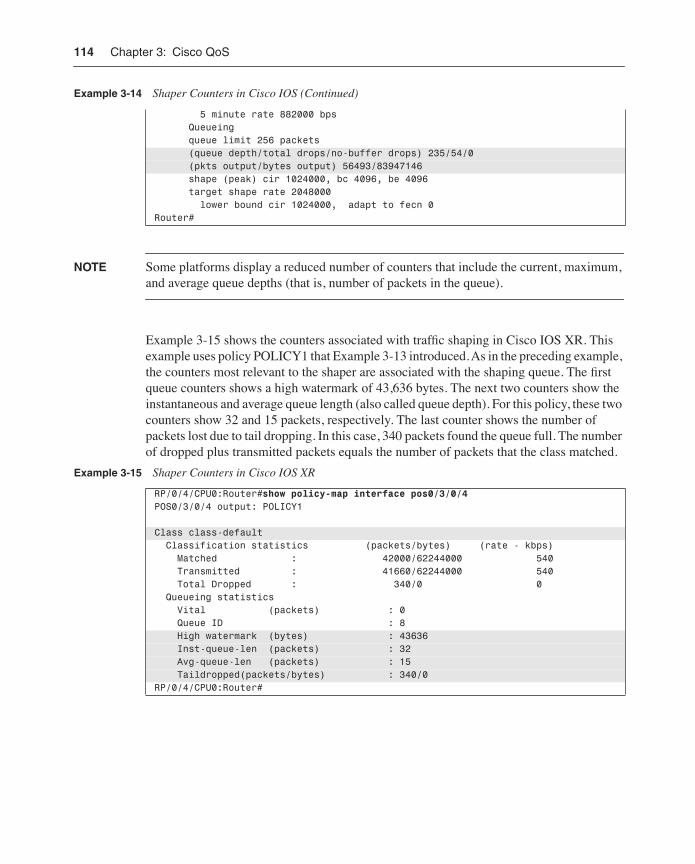
114 Chapter 3: Cisco QoS
NOTE Some platforms display a reduced number of counters that include the current, maximum, and average queue depths (that is, number of packets in the queue).
Example 3-15 shows the counters associated with traffic shaping in Cisco IOS XR. This example uses policy POLICY1 that Example 3-13 introduced. As in the preceding example, the counters most relevant to the shaper are associated with the shaping queue. The first queue counters shows a high watermark of 43,636 bytes. The next two counters show the instantaneous and average queue length (also called queue depth). For this policy, these two counters show 32 and 15 packets, respectively. The last counter shows the number of packets lost due to tail dropping. In this case, 340 packets found the queue full. The number of dropped plus transmitted packets equals the number of packets that the class matched.
5 minute rate 882000 bps Queueing queue limit 256 packets (queue depth/total drops/no-buffer drops) 235/54/0 (pkts output/bytes output) 56493/83947146 shape (peak) cir 1024000, bc 4096, be 4096 target shape rate 2048000 lower bound cir 1024000, adapt to fecn 0Router#
Example 3-15 Shaper Counters in Cisco IOS XR
RP/0/4/CPU0:Router#show policy-map interface pos0/3/0/4POS0/3/0/4 output: POLICY1
Class class-default Classification statistics (packets/bytes) (rate - kbps) Matched : 42000/62244000 540 Transmitted : 41660/62244000 540 Total Dropped : 340/0 0 Queueing statistics Vital (packets) : 0 Queue ID : 8 High watermark (bytes) : 43636 Inst-queue-len (packets) : 32 Avg-queue-len (packets) : 15 Taildropped(packets/bytes) : 340/0RP/0/4/CPU0:Router#
Example 3-14 Shaper Counters in Cisco IOS (Continued)
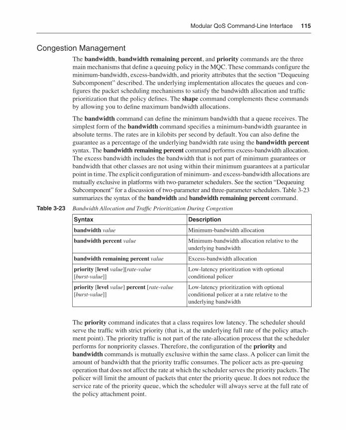
Modular QoS Command-Line Interface 115
Congestion Management The bandwidth, bandwidth remaining percent, and priority commands are the three main mechanisms that define a queuing policy in the MQC. These commands configure the minimum-bandwidth, excess-bandwidth, and priority attributes that the section “Dequeuing Subcomponent” described. The underlying implementation allocates the queues and con-figures the packet scheduling mechanisms to satisfy the bandwidth allocation and traffic prioritization that the policy defines. The shape command complements these commands by allowing you to define maximum bandwidth allocations.
The bandwidth command can define the minimum bandwidth that a queue receives. The simplest form of the bandwidth command specifies a minimum-bandwidth guarantee in absolute terms. The rates are in kilobits per second by default. You can also define the guarantee as a percentage of the underlying bandwidth rate using the bandwidth percent syntax. The bandwidth remaining percent command performs excess-bandwidth allocation. The excess bandwidth includes the bandwidth that is not part of minimum guarantees or bandwidth that other classes are not using within their minimum guarantees at a particular point in time. The explicit configuration of minimum- and excess-bandwidth allocations are mutually exclusive in platforms with two-parameter schedulers. See the section “Dequeuing Subcomponent” for a discussion of two-parameter and three-parameter schedulers. Table 3-23 summarizes the syntax of the bandwidth and bandwidth remaining percent command.
The priority command indicates that a class requires low latency. The scheduler should serve the traffic with strict priority (that is, at the underlying full rate of the policy attach-ment point). The priority traffic is not part of the rate-allocation process that the scheduler performs for nonpriority classes. Therefore, the configuration of the priority and bandwidth commands is mutually exclusive within the same class. A policer can limit the amount of bandwidth that the priority traffic consumes. The policer acts as pre-queuing operation that does not affect the rate at which the scheduler serves the priority packets. The policer will limit the amount of packets that enter the priority queue. It does not reduce the service rate of the priority queue, which the scheduler will always serve at the full rate of the policy attachment point.
Table 3-23 Bandwidth Allocation and Traffic Prioritization During Congestion
Syntax Description
bandwidth value Minimum-bandwidth allocation
bandwidth percent value Minimum-bandwidth allocation relative to the underlying bandwidth
bandwidth remaining percent value Excess-bandwidth allocation
priority [level value][rate-value [burst-value]]
Low-latency prioritization with optional conditional policer
priority [level value] percent [rate-value [burst-value]]
Low-latency prioritization with optional conditional policer at a rate relative to the underlying bandwidth
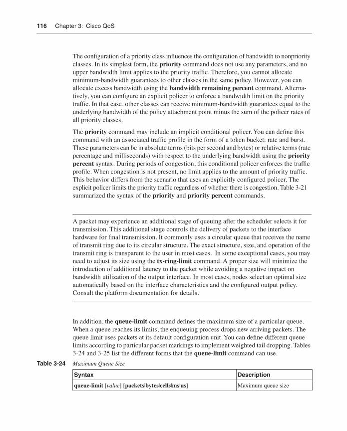
116 Chapter 3: Cisco QoS
The configuration of a priority class influences the configuration of bandwidth to nonpriority classes. In its simplest form, the priority command does not use any parameters, and no upper bandwidth limit applies to the priority traffic. Therefore, you cannot allocate minimum-bandwidth guarantees to other classes in the same policy. However, you can allocate excess bandwidth using the bandwidth remaining percent command. Alterna-tively, you can configure an explicit policer to enforce a bandwidth limit on the priority traffic. In that case, other classes can receive minimum-bandwidth guarantees equal to the underlying bandwidth of the policy attachment point minus the sum of the policer rates of all priority classes.
The priority command may include an implicit conditional policer. You can define this command with an associated traffic profile in the form of a token bucket: rate and burst. These parameters can be in absolute terms (bits per second and bytes) or relative terms (rate percentage and milliseconds) with respect to the underlying bandwidth using the priority percent syntax. During periods of congestion, this conditional policer enforces the traffic profile. When congestion is not present, no limit applies to the amount of priority traffic. This behavior differs from the scenario that uses an explicitly configured policer. The explicit policer limits the priority traffic regardless of whether there is congestion. Table 3-21 summarized the syntax of the priority and priority percent commands.
A packet may experience an additional stage of queuing after the scheduler selects it for transmission. This additional stage controls the delivery of packets to the interface hardware for final transmission. It commonly uses a circular queue that receives the name of transmit ring due to its circular structure. The exact structure, size, and operation of the transmit ring is transparent to the user in most cases. In some exceptional cases, you may need to adjust its size using the tx-ring-limit command. A proper size will minimize the introduction of additional latency to the packet while avoiding a negative impact on bandwidth utilization of the output interface. In most cases, nodes select an optimal size automatically based on the interface characteristics and the configured output policy. Consult the platform documentation for details.
In addition, the queue-limit command defines the maximum size of a particular queue. When a queue reaches its limits, the enqueuing process drops new arriving packets. The queue limit uses packets at its default configuration unit. You can define different queue limits according to particular packet markings to implement weighted tail dropping. Tables 3-24 and 3-25 list the different forms that the queue-limit command can use.
Table 3-24 Maximum Queue Size
Syntax Description
queue-limit [value] [packets|bytes|cells|ms|us] Maximum queue size
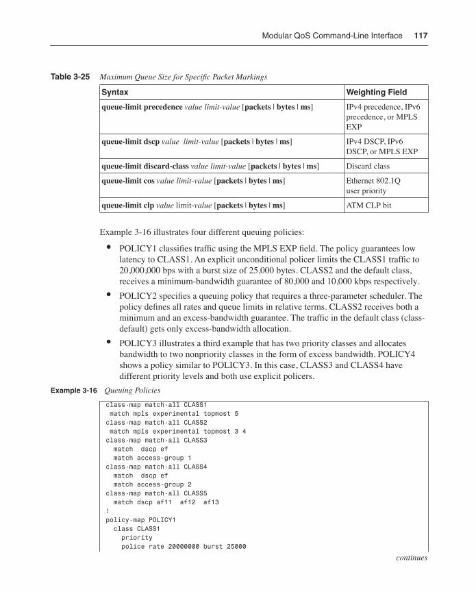
Modular QoS Command-Line Interface 117
Example 3-16 illustrates four different queuing policies:
• POLICY1 classifies traffic using the MPLS EXP field. The policy guarantees low latency to CLASS1. An explicit unconditional policer limits the CLASS1 traffic to 20,000,000 bps with a burst size of 25,000 bytes. CLASS2 and the default class, receives a minimum-bandwidth guarantee of 80,000 and 10,000 kbps respectively.
• POLICY2 specifies a queuing policy that requires a three-parameter scheduler. The policy defines all rates and queue limits in relative terms. CLASS2 receives both a minimum and an excess-bandwidth guarantee. The traffic in the default class (class-default) gets only excess-bandwidth allocation.
• POLICY3 illustrates a third example that has two priority classes and allocates bandwidth to two nonpriority classes in the form of excess bandwidth. POLICY4 shows a policy similar to POLICY3. In this case, CLASS3 and CLASS4 have different priority levels and both use explicit policers.
Table 3-25 Maximum Queue Size for Specific Packet Markings
Syntax Weighting Field
queue-limit precedence value limit-value [packets | bytes | ms] IPv4 precedence, IPv6 precedence, or MPLS EXP
queue-limit dscp value limit-value [packets | bytes | ms] IPv4 DSCP, IPv6 DSCP, or MPLS EXP
queue-limit discard-class value limit-value [packets | bytes | ms] Discard class
queue-limit cos value limit-value [packets | bytes | ms] Ethernet 802.1Q user priority
queue-limit clp value limit-value [packets | bytes | ms] ATM CLP bit
Example 3-16 Queuing Policies
class-map match-all CLASS1 match mpls experimental topmost 5class-map match-all CLASS2 match mpls experimental topmost 3 4class-map match-all CLASS3 match dscp ef match access-group 1class-map match-all CLASS4 match dscp ef match access-group 2class-map match-all CLASS5 match dscp af11 af12 af13!policy-map POLICY1 class CLASS1 priority police rate 20000000 burst 25000
continues
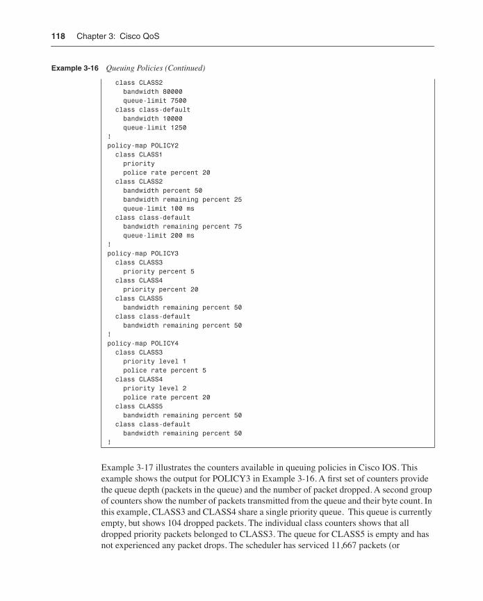
118 Chapter 3: Cisco QoS
Example 3-17 illustrates the counters available in queuing policies in Cisco IOS. This example shows the output for POLICY3 in Example 3-16. A first set of counters provide the queue depth (packets in the queue) and the number of packet dropped. A second group of counters show the number of packets transmitted from the queue and their byte count. In this example, CLASS3 and CLASS4 share a single priority queue. This queue is currently empty, but shows 104 dropped packets. The individual class counters shows that all dropped priority packets belonged to CLASS3. The queue for CLASS5 is empty and has not experienced any packet drops. The scheduler has serviced 11,667 packets (or
class CLASS2 bandwidth 80000 queue-limit 7500 class class-default bandwidth 10000 queue-limit 1250!policy-map POLICY2 class CLASS1 priority police rate percent 20 class CLASS2 bandwidth percent 50 bandwidth remaining percent 25 queue-limit 100 ms class class-default bandwidth remaining percent 75 queue-limit 200 ms!policy-map POLICY3 class CLASS3 priority percent 5 class CLASS4 priority percent 20 class CLASS5 bandwidth remaining percent 50 class class-default bandwidth remaining percent 50!policy-map POLICY4 class CLASS3 priority level 1 police rate percent 5 class CLASS4 priority level 2 police rate percent 20 class CLASS5 bandwidth remaining percent 50 class class-default bandwidth remaining percent 50!
Example 3-16 Queuing Policies (Continued)
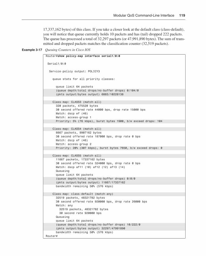
Modular QoS Command-Line Interface 119
17,337,162 bytes) of this class. If you take a closer look at the default class (class-default), you will notice that queue currently holds 10 packets and has (tail) dropped 222 packets. The queue has processed a total of 32,297 packets (or 47,991,890 bytes). The sum of trans-mitted and dropped packets matches the classification counter (32,519 packets).
Example 3-17 Queuing Counters in Cisco IOS
Router#show policy-map interface serial1/0:0
Serial1/0:0
Service-policy output: POLICY3
queue stats for all priority classes: queue limit 64 packets (queue depth/total drops/no-buffer drops) 0/104/0 (pkts output/bytes output) 6883/10228138
Class-map: CLASS3 (match-all) 320 packets, 475520 bytes 30 second offered rate 44000 bps, drop rate 15000 bps Match: dscp ef (46) Match: access-group 1 Priority: 5% (76 kbps), burst bytes 1900, b/w exceed drops: 104
Class-map: CLASS4 (match-all) 6667 packets, 9907162 bytes 30 second offered rate 187000 bps, drop rate 0 bps Match: dscp ef (46) Match: access-group 2 Priority: 20% (307 kbps), burst bytes 7650, b/w exceed drops: 0
Class-map: CLASS5 (match-all) 11667 packets, 17337162 bytes 30 second offered rate 324000 bps, drop rate 0 bps Match: dscp af11 (10) af12 (12) af13 (14) Queueing queue limit 64 packets (queue depth/total drops/no-buffer drops) 0/0/0 (pkts output/bytes output) 11667/17337162 bandwidth remaining 50% (576 kbps)
Class-map: class-default (match-any) 32519 packets, 48321782 bytes 30 second offered rate 920000 bps, drop rate 26000 bps Match: any 32519 packets, 48321782 bytes 30 second rate 920000 bps Queueing queue limit 64 packets (queue depth/total drops/no-buffer drops) 10/222/0 (pkts output/bytes output) 32297/47991890 bandwidth remaining 50% (576 kbps)Router#
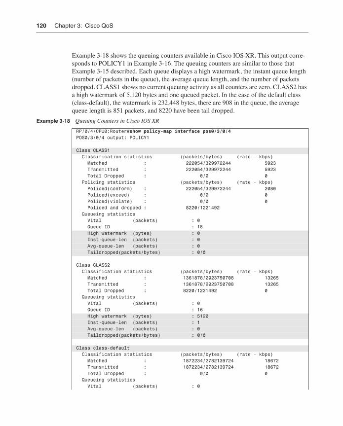
120 Chapter 3: Cisco QoS
Example 3-18 shows the queuing counters available in Cisco IOS XR. This output corre-sponds to POLICY1 in Example 3-16. The queuing counters are similar to those that Example 3-15 described. Each queue displays a high watermark, the instant queue length (number of packets in the queue), the average queue length, and the number of packets dropped. CLASS1 shows no current queuing activity as all counters are zero. CLASS2 has a high watermark of 5,120 bytes and one queued packet. In the case of the default class (class-default), the watermark is 232,448 bytes, there are 908 in the queue, the average queue length is 851 packets, and 8220 have been tail dropped.
Example 3-18 Queuing Counters in Cisco IOS XR
RP/0/4/CPU0:Router#show policy-map interface pos0/3/0/4POS0/3/0/4 output: POLICY1
Class CLASS1 Classification statistics (packets/bytes) (rate - kbps) Matched : 222054/329972244 5923 Transmitted : 222054/329972244 5923 Total Dropped : 0/0 0 Policing statistics (packets/bytes) (rate - kbps) Policed(conform) : 222054/329972244 2080 Policed(exceed) : 0/0 0 Policed(violate) : 0/0 0 Policed and dropped : 8220/1221492 Queueing statistics Vital (packets) : 0 Queue ID : 18 High watermark (bytes) : 0 Inst-queue-len (packets) : 0 Avg-queue-len (packets) : 0 Taildropped(packets/bytes) : 0/0
Class CLASS2 Classification statistics (packets/bytes) (rate - kbps) Matched : 1361878/2023750708 13265 Transmitted : 1361878/2023750708 13265 Total Dropped : 8220/1221492 0 Queueing statistics Vital (packets) : 0 Queue ID : 16 High watermark (bytes) : 5120 Inst-queue-len (packets) : 1 Avg-queue-len (packets) : 0 Taildropped(packets/bytes) : 0/0
Class class-default Classification statistics (packets/bytes) (rate - kbps) Matched : 1872234/2782139724 18672 Transmitted : 1872234/2782139724 18672 Total Dropped : 0/0 0 Queueing statistics Vital (packets) : 0
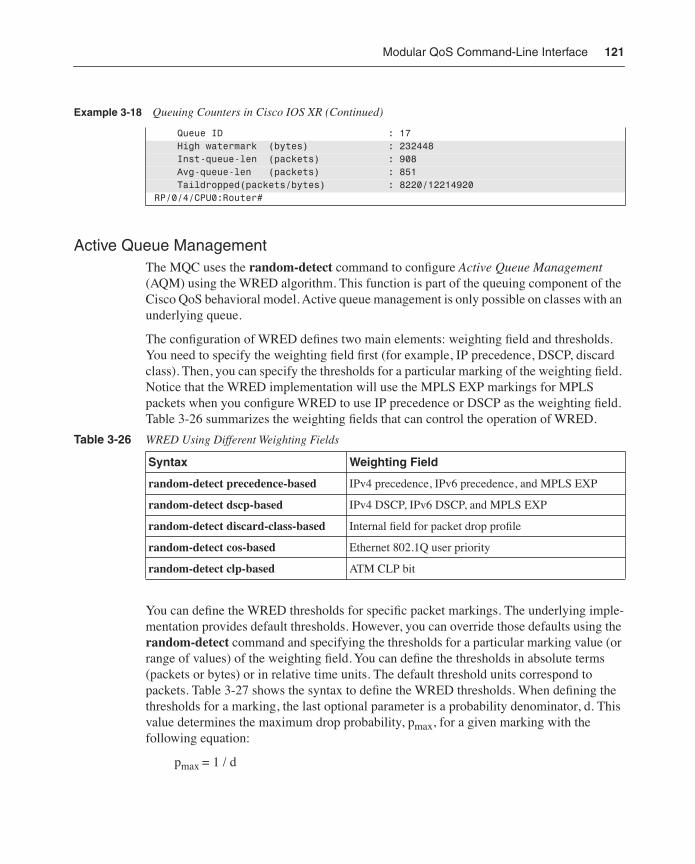
Modular QoS Command-Line Interface 121
Active Queue ManagementThe MQC uses the random-detect command to configure Active Queue Management (AQM) using the WRED algorithm. This function is part of the queuing component of the Cisco QoS behavioral model. Active queue management is only possible on classes with an underlying queue.
The configuration of WRED defines two main elements: weighting field and thresholds. You need to specify the weighting field first (for example, IP precedence, DSCP, discard class). Then, you can specify the thresholds for a particular marking of the weighting field. Notice that the WRED implementation will use the MPLS EXP markings for MPLS packets when you configure WRED to use IP precedence or DSCP as the weighting field. Table 3-26 summarizes the weighting fields that can control the operation of WRED.
You can define the WRED thresholds for specific packet markings. The underlying imple-mentation provides default thresholds. However, you can override those defaults using the random-detect command and specifying the thresholds for a particular marking value (or range of values) of the weighting field. You can define the thresholds in absolute terms (packets or bytes) or in relative time units. The default threshold units correspond to packets. Table 3-27 shows the syntax to define the WRED thresholds. When defining the thresholds for a marking, the last optional parameter is a probability denominator, d. This value determines the maximum drop probability, pmax, for a given marking with the following equation:
pmax = 1 / d
Queue ID : 17 High watermark (bytes) : 232448 Inst-queue-len (packets) : 908 Avg-queue-len (packets) : 851 Taildropped(packets/bytes) : 8220/12214920RP/0/4/CPU0:Router#
Table 3-26 WRED Using Different Weighting Fields
Syntax Weighting Field
random-detect precedence-based IPv4 precedence, IPv6 precedence, and MPLS EXP
random-detect dscp-based IPv4 DSCP, IPv6 DSCP, and MPLS EXP
random-detect discard-class-based Internal field for packet drop profile
random-detect cos-based Ethernet 802.1Q user priority
random-detect clp-based ATM CLP bit
Example 3-18 Queuing Counters in Cisco IOS XR (Continued)
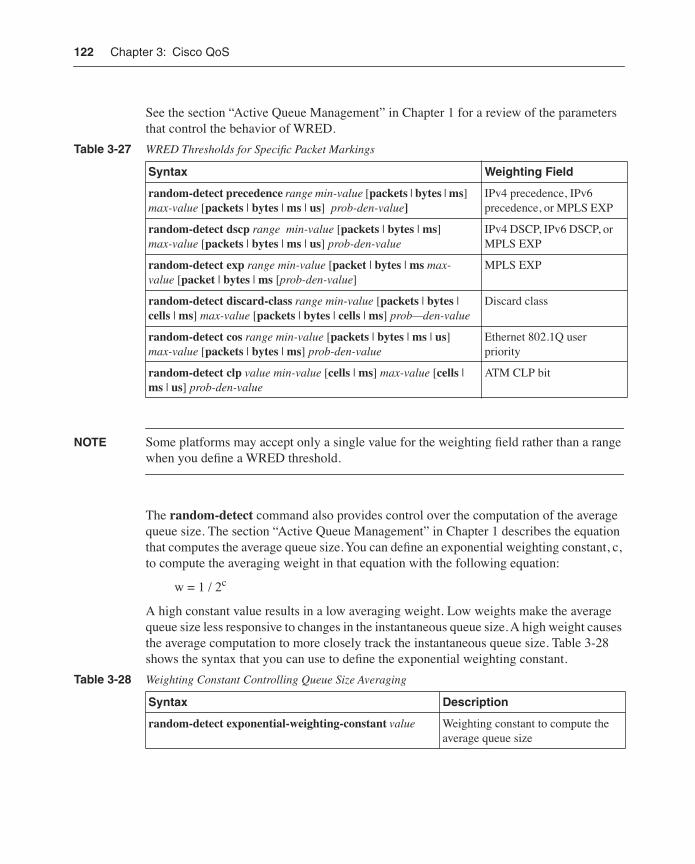
122 Chapter 3: Cisco QoS
See the section “Active Queue Management” in Chapter 1 for a review of the parameters that control the behavior of WRED.
NOTE Some platforms may accept only a single value for the weighting field rather than a range when you define a WRED threshold.
The random-detect command also provides control over the computation of the average queue size. The section “Active Queue Management” in Chapter 1 describes the equation that computes the average queue size. You can define an exponential weighting constant, c, to compute the averaging weight in that equation with the following equation:
w = 1 / 2c
A high constant value results in a low averaging weight. Low weights make the average queue size less responsive to changes in the instantaneous queue size. A high weight causes the average computation to more closely track the instantaneous queue size. Table 3-28 shows the syntax that you can use to define the exponential weighting constant.
Table 3-27 WRED Thresholds for Specific Packet Markings
Syntax Weighting Field
random-detect precedence range min-value [packets | bytes | ms] max-value [packets | bytes | ms | us] prob-den-value]
IPv4 precedence, IPv6 precedence, or MPLS EXP
random-detect dscp range min-value [packets | bytes | ms] max-value [packets | bytes | ms | us] prob-den-value
IPv4 DSCP, IPv6 DSCP, or MPLS EXP
random-detect exp range min-value [packet | bytes | ms max-value [packet | bytes | ms [prob-den-value]
MPLS EXP
random-detect discard-class range min-value [packets | bytes | cells | ms] max-value [packets | bytes | cells | ms] prob—den-value
Discard class
random-detect cos range min-value [packets | bytes | ms | us] max-value [packets | bytes | ms] prob-den-value
Ethernet 802.1Q user priority
random-detect clp value min-value [cells | ms] max-value [cells | ms | us] prob-den-value
ATM CLP bit
Table 3-28 Weighting Constant Controlling Queue Size Averaging
Syntax Description
random-detect exponential-weighting-constant value Weighting constant to compute the average queue size
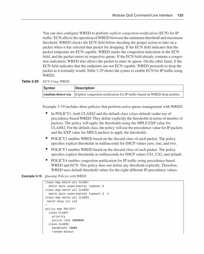
Modular QoS Command-Line Interface 123
You can also configure WRED to perform explicit congestion notification (ECN) for IP traffic. ECN affects the operation of WRED between the minimum threshold and maximum threshold. WRED checks the ECN field before deciding the proper action to take on a packet when it has selected that packet for dropping. If the ECN field indicates that the packet endpoints are ECN capable, WRED marks the congestion indication in the ECN field, and the packet enters its respective queue. If the ECN field already contains a conges-tion indication, WRED also allows the packet to enter its queue. On the other hand, if the ECN field indicates that the endpoints are not ECN capable, WRED proceeds to drop the packet as it normally would. Table 3-29 shows the syntax to enable ECN for IP traffic using WRED.
Example 3-19 includes three policies that perform active queue management with WRED:
• In POLICY1, both CLASS2 and the default class (class-default) make use of precedence-based WRED. They define explicitly the thresholds in terms of number of packets. The policy will apply the thresholds using the MPLS EXP value for CLASS2. For the default class, the policy will use the precedence value for IP packets and the EXP value for MPLS packets to apply the thresholds.
• POLICY2 enables WRED based on the discard class of each packet. The policy specifies explicit thresholds in milliseconds for DSCP values zero, one, and two.
• POLICY3 enables WRED based on the discard class of each packet. The policy specifies explicit thresholds in milliseconds for DSCP values CS1, CS2, and default.
• POLICY4 enables congestion notification for IP traffic using precedence-based WRED and ECN. This policy does not define any threshold explicitly. Therefore, WRED uses default threshold values for the eight different IP precedence values.
Table 3-29 ECN Using WRED
Syntax Description
random-detect ecn Explicit congestion notification for IP traffic based on WRED drop profiles
Example 3-19 Queuing Policies with WRED
class-map match-all CLASS1 match mpls experimental topmost 5 class-map match-all CLASS2 match mpls experimental topmost 3 4 class-map match-all CLASS3 match dscp cs1 cs2!policy-map POLICY1 class CLASS1 priority police rate 2000000 class CLASS2 bandwidth 10000 random-detect
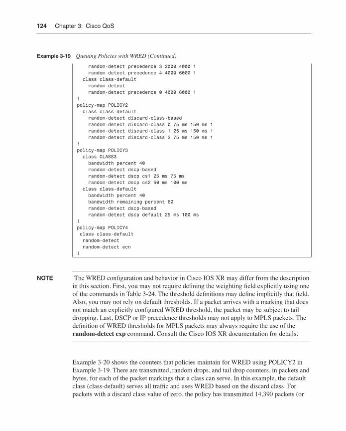
124 Chapter 3: Cisco QoS
NOTE The WRED configuration and behavior in Cisco IOS XR may differ from the description in this section. First, you may not require defining the weighting field explicitly using one of the commands in Table 3-24. The threshold definitions may define implicitly that field. Also, you may not rely on default thresholds. If a packet arrives with a marking that does not match an explicitly configured WRED threshold, the packet may be subject to tail dropping. Last, DSCP or IP precedence thresholds may not apply to MPLS packets. The definition of WRED thresholds for MPLS packets may always require the use of the random-detect exp command. Consult the Cisco IOS XR documentation for details.
Example 3-20 shows the counters that policies maintain for WRED using POLICY2 in Example 3-19. There are transmitted, random drops, and tail drop counters, in packets and bytes, for each of the packet markings that a class can serve. In this example, the default class (class-default) serves all traffic and uses WRED based on the discard class. For packets with a discard class value of zero, the policy has transmitted 14,390 packets (or
random-detect precedence 3 2000 4000 1 random-detect precedence 4 4000 6000 1 class class-default random-detect random-detect precedence 0 4000 6000 1!policy-map POLICY2 class class-default random-detect discard-class-based random-detect discard-class 0 75 ms 150 ms 1 random-detect discard-class 1 25 ms 150 ms 1 random-detect discard-class 2 75 ms 150 ms 1!policy-map POLICY3 class CLASS3 bandwidth percent 40 random-detect dscp-based random-detect dscp cs1 25 ms 75 ms random-detect dscp cs2 50 ms 100 ms class class-default bandwidth percent 40 bandwidth remaining percent 60 random-detect dscp-based random-detect dscp default 25 ms 100 ms ! policy-map POLICY4 class class-default random-detect random-detect ecn!
Example 3-19 Queuing Policies with WRED (Continued)
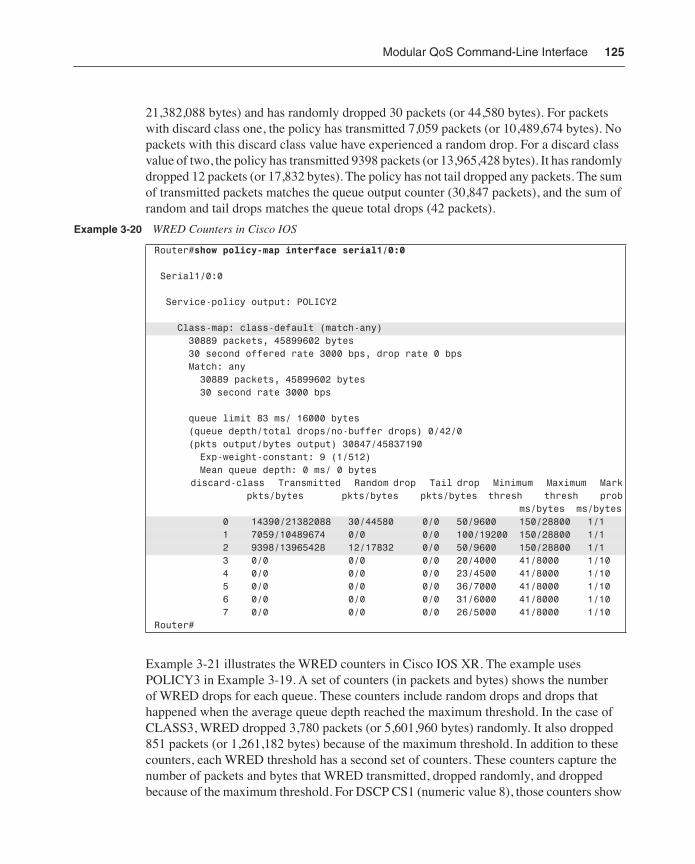
Modular QoS Command-Line Interface 125
21,382,088 bytes) and has randomly dropped 30 packets (or 44,580 bytes). For packets with discard class one, the policy has transmitted 7,059 packets (or 10,489,674 bytes). No packets with this discard class value have experienced a random drop. For a discard class value of two, the policy has transmitted 9398 packets (or 13,965,428 bytes). It has randomly dropped 12 packets (or 17,832 bytes). The policy has not tail dropped any packets. The sum of transmitted packets matches the queue output counter (30,847 packets), and the sum of random and tail drops matches the queue total drops (42 packets).
Example 3-21 illustrates the WRED counters in Cisco IOS XR. The example uses POLICY3 in Example 3-19. A set of counters (in packets and bytes) shows the number of WRED drops for each queue. These counters include random drops and drops that happened when the average queue depth reached the maximum threshold. In the case of CLASS3, WRED dropped 3,780 packets (or 5,601,960 bytes) randomly. It also dropped 851 packets (or 1,261,182 bytes) because of the maximum threshold. In addition to these counters, each WRED threshold has a second set of counters. These counters capture the number of packets and bytes that WRED transmitted, dropped randomly, and dropped because of the maximum threshold. For DSCP CS1 (numeric value 8), those counters show
Example 3-20 WRED Counters in Cisco IOS
Router#show policy-map interface serial1/0:0
Serial1/0:0
Service-policy output: POLICY2
Class-map: class-default (match-any) 30889 packets, 45899602 bytes 30 second offered rate 3000 bps, drop rate 0 bps Match: any 30889 packets, 45899602 bytes 30 second rate 3000 bps queue limit 83 ms/ 16000 bytes (queue depth/total drops/no-buffer drops) 0/42/0 (pkts output/bytes output) 30847/45837190 Exp-weight-constant: 9 (1/512) Mean queue depth: 0 ms/ 0 bytes discard-class Transmitted Random drop Tail drop Minimum Maximum Mark pkts/bytes pkts/bytes pkts/bytes thresh thresh prob ms/bytes ms/bytes 0 14390/21382088 30/44580 0/0 50/9600 150/28800 1/1 1 7059/10489674 0/0 0/0 100/19200 150/28800 1/1 2 9398/13965428 12/17832 0/0 50/9600 150/28800 1/1 3 0/0 0/0 0/0 20/4000 41/8000 1/10 4 0/0 0/0 0/0 23/4500 41/8000 1/10 5 0/0 0/0 0/0 36/7000 41/8000 1/10 6 0/0 0/0 0/0 31/6000 41/8000 1/10 7 0/0 0/0 0/0 26/5000 41/8000 1/10Router#
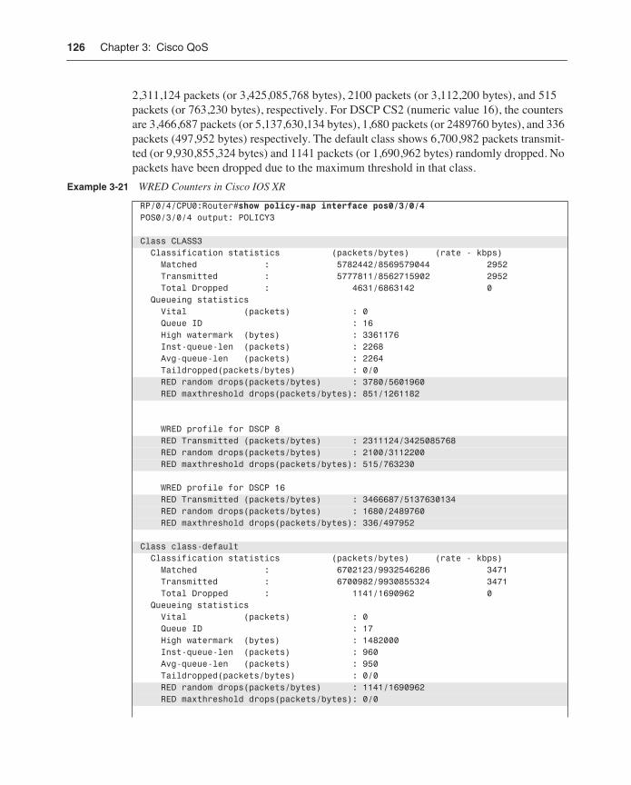
126 Chapter 3: Cisco QoS
2,311,124 packets (or 3,425,085,768 bytes), 2100 packets (or 3,112,200 bytes), and 515 packets (or 763,230 bytes), respectively. For DSCP CS2 (numeric value 16), the counters are 3,466,687 packets (or 5,137,630,134 bytes), 1,680 packets (or 2489760 bytes), and 336 packets (497,952 bytes) respectively. The default class shows 6,700,982 packets transmit-ted (or 9,930,855,324 bytes) and 1141 packets (or 1,690,962 bytes) randomly dropped. No packets have been dropped due to the maximum threshold in that class.
Example 3-21 WRED Counters in Cisco IOS XR
RP/0/4/CPU0:Router#show policy-map interface pos0/3/0/4POS0/3/0/4 output: POLICY3
Class CLASS3 Classification statistics (packets/bytes) (rate - kbps) Matched : 5782442/8569579044 2952 Transmitted : 5777811/8562715902 2952 Total Dropped : 4631/6863142 0 Queueing statistics Vital (packets) : 0 Queue ID : 16 High watermark (bytes) : 3361176 Inst-queue-len (packets) : 2268 Avg-queue-len (packets) : 2264 Taildropped(packets/bytes) : 0/0 RED random drops(packets/bytes) : 3780/5601960 RED maxthreshold drops(packets/bytes): 851/1261182
WRED profile for DSCP 8 RED Transmitted (packets/bytes) : 2311124/3425085768 RED random drops(packets/bytes) : 2100/3112200 RED maxthreshold drops(packets/bytes): 515/763230
WRED profile for DSCP 16 RED Transmitted (packets/bytes) : 3466687/5137630134 RED random drops(packets/bytes) : 1680/2489760 RED maxthreshold drops(packets/bytes): 336/497952
Class class-default Classification statistics (packets/bytes) (rate - kbps) Matched : 6702123/9932546286 3471 Transmitted : 6700982/9930855324 3471 Total Dropped : 1141/1690962 0 Queueing statistics Vital (packets) : 0 Queue ID : 17 High watermark (bytes) : 1482000 Inst-queue-len (packets) : 960 Avg-queue-len (packets) : 950 Taildropped(packets/bytes) : 0/0 RED random drops(packets/bytes) : 1141/1690962 RED maxthreshold drops(packets/bytes): 0/0
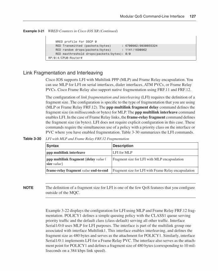
Modular QoS Command-Line Interface 127
Link Fragmentation and InterleavingCisco IOS supports LFI with Multilink PPP (MLP) and Frame Relay encapsulation. You can use MLP for LFI on serial interfaces, dialer interfaces, ATM PVCs, or Frame Relay PVCs. Cisco Frame Relay also support native fragmentation using FRF.11 and FRF.12.
The configuration of link fragmentation and interleaving (LFI) requires the definition of a fragment size. The configuration is specific to the type of fragmentation that you are using (MLP or Frame Relay FRF.12). The ppp multilink fragment delay command defines the fragment size (in milliseconds or bytes) for MLP. The ppp multilink interleave command enables LFI. In the case of Frame Relay links, the frame-relay fragment command defines the fragment size (in bytes). LFI does not require explicit configuration in this case. These commands require the simultaneous use of a policy with a priority class on the interface or PVC where you have enabled fragmentation. Table 3-30 summarizes the LFI commands.
NOTE The definition of a fragment size for LFI is one of the few QoS features that you configure outside of the MQC.
Example 3-22 displays the configuration for LFI using MLP and Frame Relay FRF.12 frag-mentation. POLICY1 defines a simple queuing policy with the CLASS1 queue serving priority traffic and the default class (class-default) serving all other traffic. Interface Serial1/0:0 uses MLP for LFI purposes. The interface is part of the multilink group one associated with interface Multilink1. This interface enables interleaving, and defines the fragment size as 480 bytes and serves as the attachment for POLICY1. Similarly, interface Serial1/0:1 implements LFI for a Frame Relay PVC. The interface also serves as the attach-ment point for POLICY1 and defines a fragment size of 480 bytes (corresponding to 10 mil-liseconds on a 384 kbps link speed).
WRED profile for DSCP 0 RED Transmitted (packets/bytes) : 6700982/9930855324 RED random drops(packets/bytes) : 1141/1690962 RED maxthreshold drops(packets/bytes): 0/0RP/0/4/CPU0:Router#
Table 3-30 LFI with MLP and Frame Relay FRF.12 Fragmentation
Syntax Description
ppp multilink interleave LFI for MLP
ppp multilink fragment {delay value | size value}
Fragment size for LFI with MLP encapsulation
frame-relay fragment value end-to-end Fragment size for LFI with Frame Relay encapsulation
Example 3-21 WRED Counters in Cisco IOS XR (Continued)
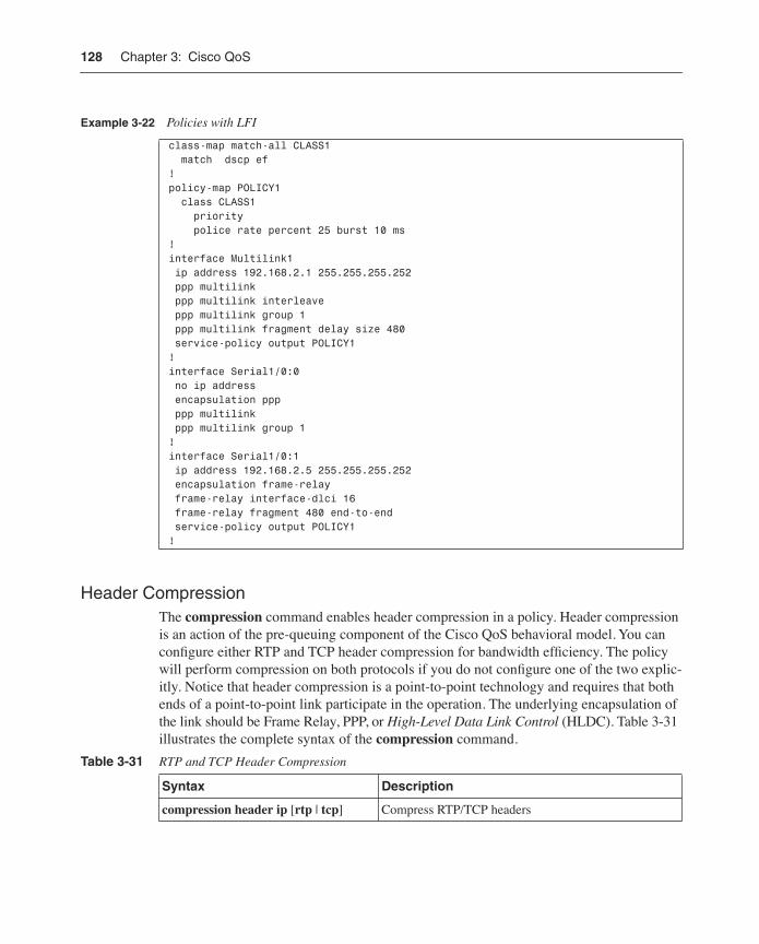
128 Chapter 3: Cisco QoS
Header CompressionThe compression command enables header compression in a policy. Header compression is an action of the pre-queuing component of the Cisco QoS behavioral model. You can configure either RTP and TCP header compression for bandwidth efficiency. The policy will perform compression on both protocols if you do not configure one of the two explic-itly. Notice that header compression is a point-to-point technology and requires that both ends of a point-to-point link participate in the operation. The underlying encapsulation of the link should be Frame Relay, PPP, or High-Level Data Link Control (HLDC). Table 3-31 illustrates the complete syntax of the compression command.
Example 3-22 Policies with LFI
class-map match-all CLASS1 match dscp ef !policy-map POLICY1 class CLASS1 priority police rate percent 25 burst 10 ms!interface Multilink1 ip address 192.168.2.1 255.255.255.252 ppp multilink ppp multilink interleave ppp multilink group 1 ppp multilink fragment delay size 480 service-policy output POLICY1!interface Serial1/0:0 no ip address encapsulation ppp ppp multilink ppp multilink group 1!interface Serial1/0:1 ip address 192.168.2.5 255.255.255.252 encapsulation frame-relay frame-relay interface-dlci 16 frame-relay fragment 480 end-to-end service-policy output POLICY1!
Table 3-31 RTP and TCP Header Compression
Syntax Description
compression header ip [rtp | tcp] Compress RTP/TCP headers
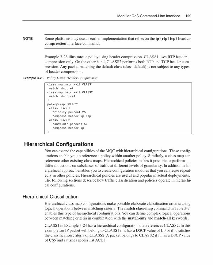
Modular QoS Command-Line Interface 129
NOTE Some platforms may use an earlier implementation that relies on the ip {rtp | tcp} header-compression interface command.
Example 3-23 illustrates a policy using header compression. CLASS1 uses RTP header compression only. On the other hand, CLASS2 performs both RTP and TCP header com-pression. Any packet matching the default class (class-default) is not subject to any types of header compression.
Hierarchical ConfigurationsYou can extend the capabilities of the MQC with hierarchical configurations. These config-urations enable you to reference a policy within another policy. Similarly, a class map can reference other existing class maps. Hierarchical policies makes it possible to perform different actions on subclasses of traffic at different levels of granularity. In addition, a hi-erarchical approach enables you to create configuration modules that you can reuse repeat-edly in other policies. Hierarchical policies are useful and popular in actual deployments. The following sections describe how traffic classification and policies operate in hierarchi-cal configurations.
Hierarchical ClassificationHierarchical class map configurations make possible elaborate classification criteria using logical operations between matching criteria. The match class-map command in Table 3-7 enables this type of hierarchical configurations. You can define complex logical operations between matching criteria in combination with the match-any and match-all keywords.
CLASS1 in Example 3-24 has a hierarchical configuration that references CLASS2. In this example, an IP packet will belong to CLASS1 if it has a DSCP value of EF or if it satisfies the classification criteria of CLASS2. A packet belongs to CLASS2 if it has a DSCP value of CS5 and satisfies access list ACL1.
Example 3-23 Policy Using Header Compression
class-map match-all CLASS1 match dscp ef class-map match-all CLASS2 match dscp cs4 !policy-map POLICY1 class CLASS1 priority percent 25 compress header ip rtp class CLASS2 bandwidth percent 50 compress header ip !
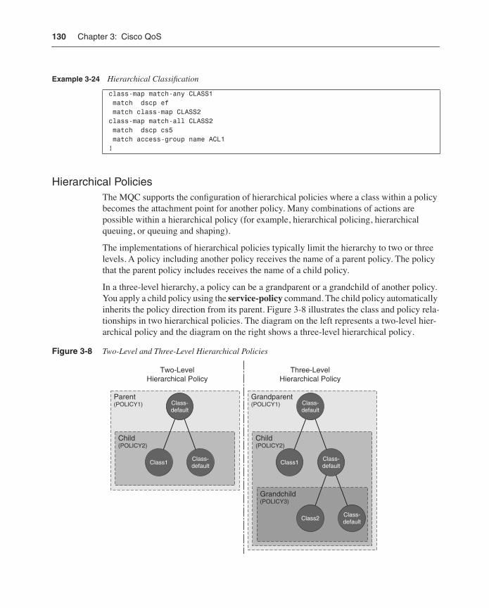
130 Chapter 3: Cisco QoS
Hierarchical PoliciesThe MQC supports the configuration of hierarchical policies where a class within a policy becomes the attachment point for another policy. Many combinations of actions are possible within a hierarchical policy (for example, hierarchical policing, hierarchical queuing, or queuing and shaping).
The implementations of hierarchical policies typically limit the hierarchy to two or three levels. A policy including another policy receives the name of a parent policy. The policy that the parent policy includes receives the name of a child policy.
In a three-level hierarchy, a policy can be a grandparent or a grandchild of another policy. You apply a child policy using the service-policy command. The child policy automatically inherits the policy direction from its parent. Figure 3-8 illustrates the class and policy rela-tionships in two hierarchical policies. The diagram on the left represents a two-level hier-archical policy and the diagram on the right shows a three-level hierarchical policy.
Figure 3-8 Two-Level and Three-Level Hierarchical Policies
Example 3-24 Hierarchical Classification
class-map match-any CLASS1 match dscp ef match class-map CLASS2class-map match-all CLASS2 match dscp cs5 match access-group name ACL1!
Class-default
Class1Class-default
Child(POLICY2)
Parent(POLICY1)
Two-LevelHierarchical Policy
Class-default
Class1
Child(POLICY2)
Class2Class-default
Grandchild(POLICY3)
Grandparent(POLICY1)
Three-LevelHierarchical Policy
Class-default
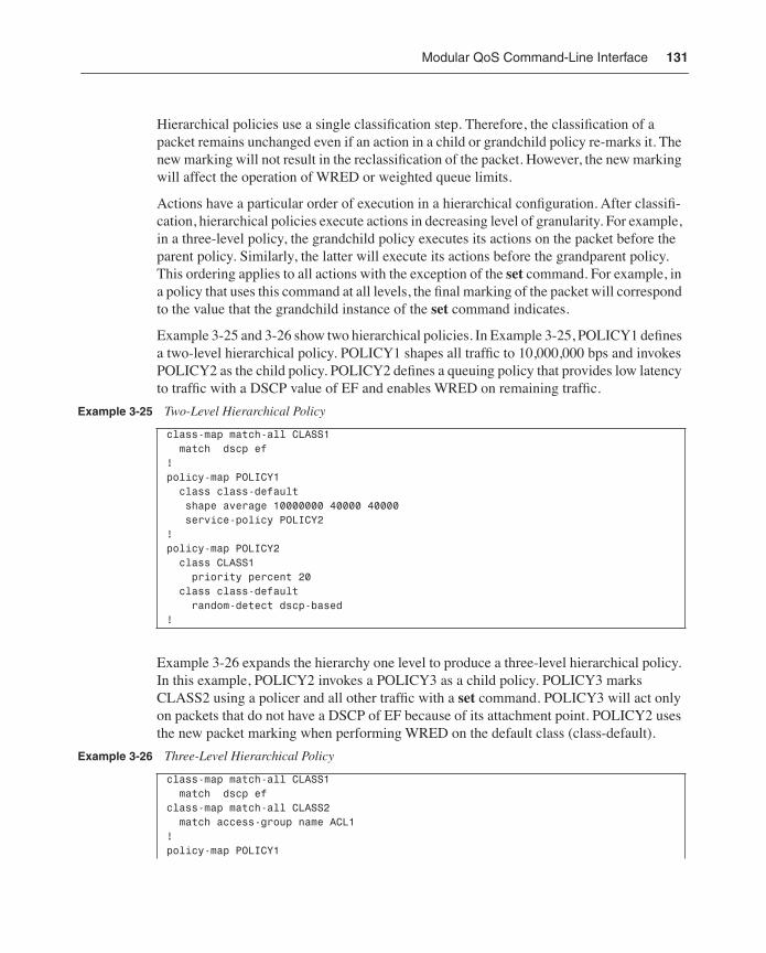
Modular QoS Command-Line Interface 131
Hierarchical policies use a single classification step. Therefore, the classification of a packet remains unchanged even if an action in a child or grandchild policy re-marks it. The new marking will not result in the reclassification of the packet. However, the new marking will affect the operation of WRED or weighted queue limits.
Actions have a particular order of execution in a hierarchical configuration. After classifi-cation, hierarchical policies execute actions in decreasing level of granularity. For example, in a three-level policy, the grandchild policy executes its actions on the packet before the parent policy. Similarly, the latter will execute its actions before the grandparent policy. This ordering applies to all actions with the exception of the set command. For example, in a policy that uses this command at all levels, the final marking of the packet will correspond to the value that the grandchild instance of the set command indicates.
Example 3-25 and 3-26 show two hierarchical policies. In Example 3-25, POLICY1 defines a two-level hierarchical policy. POLICY1 shapes all traffic to 10,000,000 bps and invokes POLICY2 as the child policy. POLICY2 defines a queuing policy that provides low latency to traffic with a DSCP value of EF and enables WRED on remaining traffic.
Example 3-26 expands the hierarchy one level to produce a three-level hierarchical policy. In this example, POLICY2 invokes a POLICY3 as a child policy. POLICY3 marks CLASS2 using a policer and all other traffic with a set command. POLICY3 will act only on packets that do not have a DSCP of EF because of its attachment point. POLICY2 uses the new packet marking when performing WRED on the default class (class-default).
Example 3-25 Two-Level Hierarchical Policy
class-map match-all CLASS1 match dscp ef !policy-map POLICY1 class class-default shape average 10000000 40000 40000 service-policy POLICY2!policy-map POLICY2 class CLASS1 priority percent 20 class class-default random-detect dscp-based!
Example 3-26 Three-Level Hierarchical Policy
class-map match-all CLASS1 match dscp ef class-map match-all CLASS2 match access-group name ACL1!policy-map POLICY1
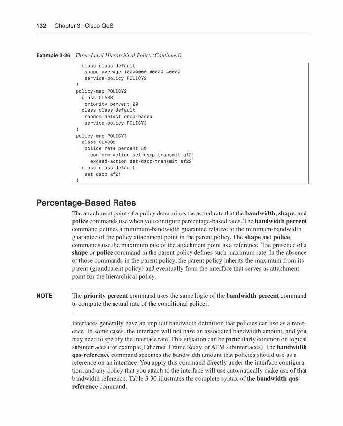
132 Chapter 3: Cisco QoS
Percentage-Based RatesThe attachment point of a policy determines the actual rate that the bandwidth, shape, and police commands use when you configure percentage-based rates. The bandwidth percent command defines a minimum-bandwidth guarantee relative to the minimum-bandwidth guarantee of the policy attachment point in the parent policy. The shape and police commands use the maximum rate of the attachment point as a reference. The presence of a shape or police command in the parent policy defines such maximum rate. In the absence of those commands in the parent policy, the parent policy inherits the maximum from its parent (grandparent policy) and eventually from the interface that serves as attachment point for the hierarchical policy.
NOTE The priority percent command uses the same logic of the bandwidth percent command to compute the actual rate of the conditional policer.
Interfaces generally have an implicit bandwidth definition that policies can use as a refer-ence. In some cases, the interface will not have an associated bandwidth amount, and you may need to specify the interface rate. This situation can be particularly common on logical subinterfaces (for example, Ethernet, Frame Relay, or ATM subinterfaces). The bandwidth qos-reference command specifies the bandwidth amount that policies should use as a reference on an interface. You apply this command directly under the interface configura-tion, and any policy that you attach to the interface will use automatically make use of that bandwidth reference. Table 3-30 illustrates the complete syntax of the bandwidth qos-reference command.
class class-default shape average 10000000 40000 40000 service-policy POLICY2!policy-map POLICY2 class CLASS1 priority percent 20 class class-default random-detect dscp-based service-policy POLICY3!policy-map POLICY3 class CLASS2 police rate percent 50 conform-action set-dscp-transmit af21 exceed-action set-dscp-transmit af22 class class-default set dscp af21!
Example 3-26 Three-Level Hierarchical Policy (Continued)
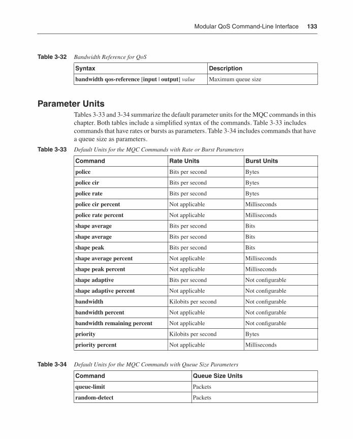
Modular QoS Command-Line Interface 133
Parameter UnitsTables 3-33 and 3-34 summarize the default parameter units for the MQC commands in this chapter. Both tables include a simplified syntax of the commands. Table 3-33 includes commands that have rates or bursts as parameters. Table 3-34 includes commands that have a queue size as parameters.
Table 3-32 Bandwidth Reference for QoS
Syntax Description
bandwidth qos-reference [input | output] value Maximum queue size
Table 3-33 Default Units for the MQC Commands with Rate or Burst Parameters
Command Rate Units Burst Units
police Bits per second Bytes
police cir Bits per second Bytes
police rate Bits per second Bytes
police cir percent Not applicable Milliseconds
police rate percent Not applicable Milliseconds
shape average Bits per second Bits
shape average Bits per second Bits
shape peak Bits per second Bits
shape average percent Not applicable Milliseconds
shape peak percent Not applicable Milliseconds
shape adaptive Bits per second Not configurable
shape adaptive percent Not applicable Not configurable
bandwidth Kilobits per second Not configurable
bandwidth percent Not applicable Not configurable
bandwidth remaining percent Not applicable Not configurable
priority Kilobits per second Bytes
priority percent Not applicable Milliseconds
Table 3-34 Default Units for the MQC Commands with Queue Size Parameters
Command Queue Size Units
queue-limit Packets
random-detect Packets
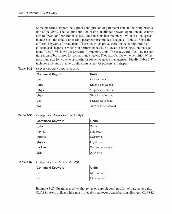
134 Chapter 3: Cisco QoS
Some platforms support the explicit configuration of parameter units in their implementa-tion of the MQC. The flexible definition of units facilitates network operation and contrib-utes to fewer configuration mistakes. Their benefits become more obvious as link speeds increase and the default units for a parameter become less adequate. Table 3-35 lists the different keywords for rate units. These keywords prove useful in the configuration of policers and shapers or when you perform bandwidth allocation for congestion manage-ment. Table 3-36 shows the keywords for memory units. These keywords facilitate the con-figuration of burst sizes for policers and shapers. They also facilitate the definition of the maximum size for a queue or thresholds for active queue management. Finally, Table 3-37 includes time units that help define burst sizes for policers and shapers.
Example 3-27 illustrates a policy that relies on explicit configuration of parameter units. CLASS1 uses a policer with a rate in megabits per second and a burst in kilobytes. CLASS2
Table 3-35 Configurable Rate Units in the MQC
Command Keyword Units
bps Bits per second
kbps Kilobits per second
mbps Megabits per second
gbps Gigabits per second
pps Packets per second
cps ATM cells per second
Table 3-36 Configurable Memory Units in the MQC
Command Keyword Units
bytes Bytes
kbytes Kilobytes
mbytes Megabytes
gbytes Gigabytes
packets Packets per second
cells ATM cells
Table 3-37 Configurable Time Units in the MQC
Command Keyword Units
ms Milliseconds
us Microseconds
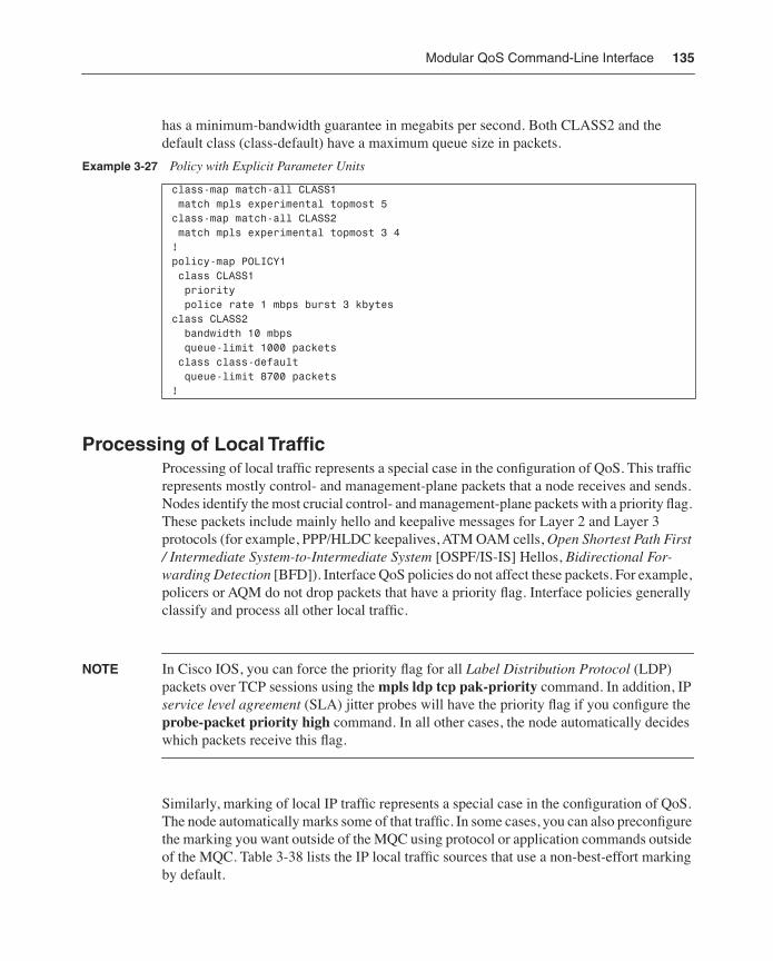
Modular QoS Command-Line Interface 135
has a minimum-bandwidth guarantee in megabits per second. Both CLASS2 and the default class (class-default) have a maximum queue size in packets.
Processing of Local TrafficProcessing of local traffic represents a special case in the configuration of QoS. This traffic represents mostly control- and management-plane packets that a node receives and sends. Nodes identify the most crucial control- and management-plane packets with a priority flag. These packets include mainly hello and keepalive messages for Layer 2 and Layer 3 protocols (for example, PPP/HLDC keepalives, ATM OAM cells, Open Shortest Path First / Intermediate System-to-Intermediate System [OSPF/IS-IS] Hellos, Bidirectional For-warding Detection [BFD]). Interface QoS policies do not affect these packets. For example, policers or AQM do not drop packets that have a priority flag. Interface policies generally classify and process all other local traffic.
NOTE In Cisco IOS, you can force the priority flag for all Label Distribution Protocol (LDP) packets over TCP sessions using the mpls ldp tcp pak-priority command. In addition, IP service level agreement (SLA) jitter probes will have the priority flag if you configure the probe-packet priority high command. In all other cases, the node automatically decides which packets receive this flag.
Similarly, marking of local IP traffic represents a special case in the configuration of QoS. The node automatically marks some of that traffic. In some cases, you can also preconfigure the marking you want outside of the MQC using protocol or application commands outside of the MQC. Table 3-38 lists the IP local traffic sources that use a non-best-effort marking by default.
Example 3-27 Policy with Explicit Parameter Units
class-map match-all CLASS1 match mpls experimental topmost 5 class-map match-all CLASS2 match mpls experimental topmost 3 4 !policy-map POLICY1 class CLASS1 priority police rate 1 mbps burst 3 kbytes class CLASS2 bandwidth 10 mbps queue-limit 1000 packets class class-default queue-limit 8700 packets !
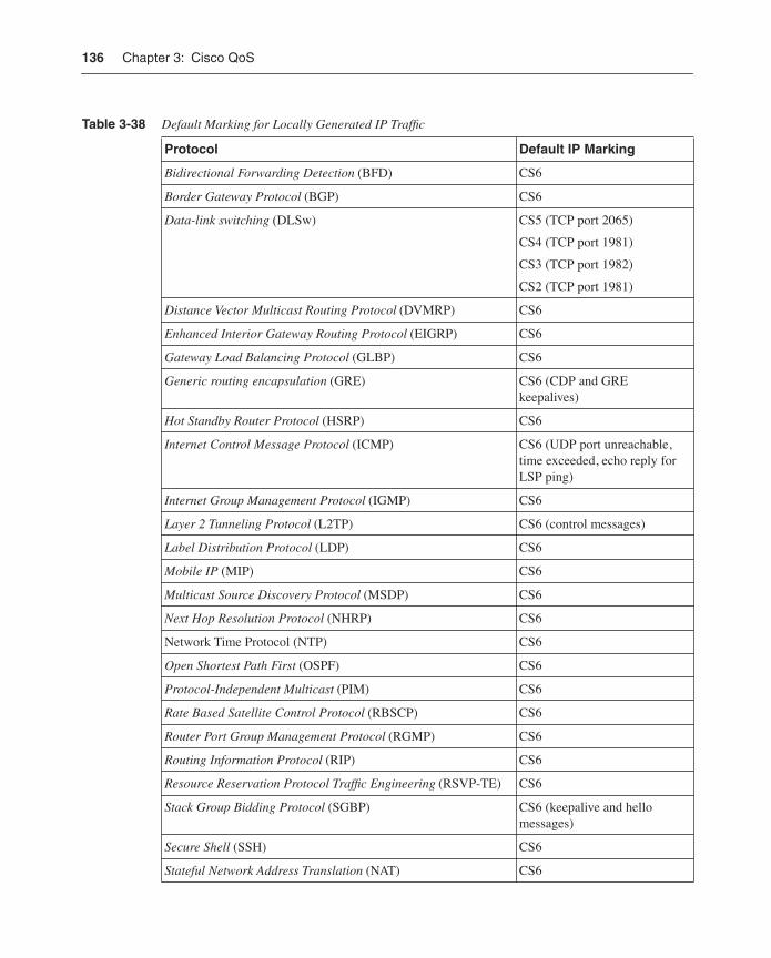
136 Chapter 3: Cisco QoS
Table 3-38 Default Marking for Locally Generated IP Traffic
Protocol Default IP Marking
Bidirectional Forwarding Detection (BFD) CS6
Border Gateway Protocol (BGP) CS6
Data-link switching (DLSw) CS5 (TCP port 2065)
CS4 (TCP port 1981)
CS3 (TCP port 1982)
CS2 (TCP port 1981)
Distance Vector Multicast Routing Protocol (DVMRP) CS6
Enhanced Interior Gateway Routing Protocol (EIGRP) CS6
Gateway Load Balancing Protocol (GLBP) CS6
Generic routing encapsulation (GRE) CS6 (CDP and GRE keepalives)
Hot Standby Router Protocol (HSRP) CS6
Internet Control Message Protocol (ICMP) CS6 (UDP port unreachable, time exceeded, echo reply for LSP ping)
Internet Group Management Protocol (IGMP) CS6
Layer 2 Tunneling Protocol (L2TP) CS6 (control messages)
Label Distribution Protocol (LDP) CS6
Mobile IP (MIP) CS6
Multicast Source Discovery Protocol (MSDP) CS6
Next Hop Resolution Protocol (NHRP) CS6
Network Time Protocol (NTP) CS6
Open Shortest Path First (OSPF) CS6
Protocol-Independent Multicast (PIM) CS6
Rate Based Satellite Control Protocol (RBSCP) CS6
Router Port Group Management Protocol (RGMP) CS6
Routing Information Protocol (RIP) CS6
Resource Reservation Protocol Traffic Engineering (RSVP-TE) CS6
Stack Group Bidding Protocol (SGBP) CS6 (keepalive and hello messages)
Secure Shell (SSH) CS6
Stateful Network Address Translation (NAT) CS6
Modular QoS Command-Line Interface 137
NOTE Cisco IOS XR supports a subset of the protocols listed in the preceding table. For those protocols it supports, the default marking behavior in Cisco IOS and Cisco IOS XR is the same.
NOTE The details of the processing of local traffic can vary slightly depending on software, hardware, and platform specifics. These differences can be particularly true regarding bandwidth allocation to local traffic in the presence of interface congestion. Consult your platform documentation for details.
Some platforms support the definition of a QoS policy to control local traffic as it flows from and to the route processor. The policies generally classify the traffic and define what packets to transmit, drop, or police. There are two main types of policy: aggregate and dis-tributed. An aggregate control-plane policy acts on the all route processor traffic. Platforms with a distributed architecture can support a set of distributed control-plane policies that act on traffic that flows between line cards and the route processor. Figure 3-9 illustrates the different attachment points for centralized and distributed architectures. The distributed control-plane policies process only traffic that needs to reach the route processor. The line card may process some local traffic (for instance, generating a ping reply) without involving the route processor.
Protocol Default IP Marking
Telnet CS6
Virtual Router Redundancy Protocol (VRRP) CS6
Table 3-38 Default Marking for Locally Generated IP Traffic (Continued)
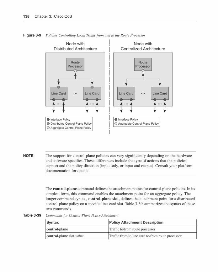
138 Chapter 3: Cisco QoS
Figure 3-9 Policies Controlling Local Traffic from and to the Route Processor
NOTE The support for control-plane policies can vary significantly depending on the hardware and software specifics. These differences include the type of actions that the policies support and the policy direction (input only, or input and output). Consult your platform documentation for details.
The control-plane command defines the attachment points for control-plane policies. In its simplest form, this command enables the attachment point for an aggregate policy. The longer command syntax, control-plane slot, defines the attachment point for a distributed control-plane policy on a specific line-card slot. Table 3-39 summarizes the syntax of these two commands.
Table 3-39 Commands for Control-Plane Policy Attachment
Syntax Policy Attachment Description
control-plane Traffic to/from route processor
control-plane slot value Traffic from/to line card to/from route processor
Node withDistributed Architecture
RouteProcessor
Line Card
Interface PolicyDistributed Control-Plane PolicyAggregate Control-Plane Policy
Interface PolicyAggregate Control-Plane Policy
…
… Line Card
…
Node withCentralized Architecture
RouteProcessor
Line Card
…
… Line Card
…
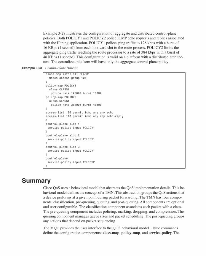
Example 3-28 illustrates the configuration of aggregate and distributed control-plane policies. Both POLICY1 and POLICY2 police ICMP echo requests and replies associated with the IP ping application. POLICY1 polices ping traffic to 128 kbps with a burst of 16 KBps (1 second) from each line-card slot to the route process. POLICY2 limits the aggregate ping traffic reaching the route processor to a rate of 384 kbps with a burst of 48 KBps (1 second). This configuration is valid on a platform with a distributed architec-ture. The centralized platform will have only the aggregate control-plane policy.
SummaryCisco QoS uses a behavioral model that abstracts the QoS implementation details. This be-havioral model defines the concept of a TMN. This abstraction groups the QoS actions that a device performs at a given point during packet forwarding. The TMN has four compo-nents: classification, pre-queuing, queuing, and post-queuing. All components are optional and user configurable. The classification component associates each packet with a class. The pre-queuing component includes policing, marking, dropping, and compression. The queuing component manages queue sizes and packet scheduling. The post-queuing groups any actions that depend on packet sequencing.
The MQC provides the user interface to the QOS behavioral model. Three commands define the configuration components: class-map, policy-map, and service-policy. The
Example 3-28 Control-Plane Policies
class-map match-all CLASS1 match access-group 100!policy-map POLICY1 class CLASS1 police rate 128000 burst 16000policy-map POLICY2 class CLASS1 police rate 384000 burst 48000!access-list 100 permit icmp any any echoaccess-list 100 permit icmp any any echo-reply!control-plane slot 1 service-policy input POLICY1!control-plane slot 2 service-policy input POLICY1!control-plane slot 3 service-policy input POLICY1!control-plane service-policy input POLICY2!
140 Chapter 3: Cisco QoS
class-map commands control traffic classification and corresponds to the classification component of the TMN. The policy-map command defines a policy template that group QoS actions (including marking, policing, shaping, congestion management, active queue management, and so on). These policies may define any of the other three components of the TMN. The service-policy command instantiates a previously defined QoS policy and defines its direction. The MQC provides a template-based, hardware-independent configu-ration model for QoS across different Cisco platforms.
ReferencesCisco Software Center: http://www.cisco.com/go/software
Cisco Software Advisor: http://tools.cisco.com/Support/Fusion/FusionHome.do
Cisco IOS Quality of Service Solutions Configuration Guide, Release 12.4: http://www.cisco.com/en/US/products/ps6350/products_configuration_guide_book09186a0080435d50.html
Cisco IOS Software Releases 12.2 S Feature Guides: http://www.cisco.com/en/US/products/sw/iosswrel/ps1838/products_feature_guides_list.html
Cisco IOS XR Software Configuration Guides: http://www.cisco.com/en/US/partner/products/ps5845/products_installation_and_configuration_guides_list.html
Traffic Management Specification Version 4.0. The ATM Forum: http://www.atmfo-rum.com/

I N D E X
AAck (Acknowledgment) messages, RSVP, 48Active Queue Management, 40–42, 121–126, 206adaptive shaping, 111adjacencies, forwarding, 172administrative group, link attribute, 59–60admission-control mechanisms, 206, 219, 234AF (Assured Forwarding)
PHBs, 17–18traffic, 227
affinities, tunnel, 157, 247affinity command, 157–158aggregate policies, 137algorithms
fair queuing, 4SPF, 60token bucket, 36WRED
Cisco IOS XR, 125counters, 125description, 41, 121, 213–215ECN, 122queuing, 123thresholds, 121weighting fields, 121
alias configuration command, 156AQM (Active Queue Management),
40–42, 121–126, 206area-local scope LSA (link-state advertisement),
60areas, OSPF, 60Assured Forwarding
See AFATM
marking, 31policing profiles, 104
ATM Forum Traffic Management specification, 104
attachment points, 85, 132attributes
configuring, 150–152links, 60priority, 82See also specifically named link attributes
audio, streaming, 204authentication, RSVP, 50autoroute feature, 172, 253Auto-tunnel feature, 253
BBA (behavior aggregate) classifiers, 9backbones
designs, 260–261DS-TE, 240–248edge nodes, 210–212FRR, 251–260IS-IS, 240MPLS TE, 219–224, 251–260OSPF, 240performance
application requirements, 201–204targets, factors affecting, 204–206
QoSbest-effort, 212–217DiffServ, 226–233DS-TE, 240–248FRR, 251–260MPLS TE, 219–224, 233–240, 251–260optimizing, 260–261
backup tunnels, 187, 259backup commands
backup-bw command, 187backup-path command, 184
bandwidthavailable, 59backup tunnels, 187, 259BDP, 213behavioral model, 83commands, 115–116, 132, 152, 157–158,
178–180congestion, 115–120constraint models, 68–71, 175, 243consumption, 202defaults, 157dequeuing, 82–83DS-TE, 179–180flooding link updates, 150FRR, 187–189
284
MAM/RDM, 68–71, 175–180, 240–243queuing, 115–118rates, percentage based, 132
bandwidth commandsbandwidth percent command, 115, 132bandwidth qos-reference command, 132bandwidth remaining percent command,
115–116bc keyword
description, 100, 109bc0 keyword, 179–180bc1 keyword, 179
BDP (delay-bandwidth product), 213be keyword, 101, 109begin keyword, 156behavior aggregate (BA) classifiers, 9behavioral model
bandwidth, 83classification, 80configuration, 84–87header compression, 128MQC, 84–87priority, 82queuing, 81
dequeuing, 82–83enqueuing, 81post-queuing, 84pre-queuing, 80–81
schedulers, 82TMN, 79–80
best-effort backbones, 213–217best-effort, 212–217DiffServ, 226–233DS-TE, 240–248FRR, 251–260MPLS TE, 219–224, 233–240, 251–260optimizing, 260–261
Bidirectional Forwarding Detection (BFD), 184bit errors, 206broadcast video, 203buffering, 37, 215Bundle messages, RSVP, 48bursts, 133–135, 202, 229burst keyword, 101bw-protect keyword, 183byte count, 118
Ccapacity
class, 226controlling, 213
CBTS (class-based tunnel selection), 173–174, 236, 246
child/parent policies, 130CIR (committed information rate), 33cir keyword, 100Cisco IOS XR
counters, clearing, 86formatting, 86headend nodes, 222–224interface commands, 163man command, 145MQC, 84policers, 107protocol markingdescription, 137queuing counters, 120shaping, 114tunnel configuration, 147WRED, 125, 217
Cisco QoS behavioral modelSee behavioral model
class-default command, 80, 88classes
capacity, 226CBTS, 173–174, 236, 246definitions, 85maps
hierarchies, 129MCQ, 85
priority, 116service, 202TE-Classes, 66, 176–177, 241–243See also CTs
classification/conditioningAQM, 40–42congestion, 37–39counters, 91–93description, 31DiffServ, 13–15header compression, 44LFI, 42–43marking, 31–32
bandwidth
285
matching, 85–88MQC hierarchies, 129policing, 32, 35shaping, 35–36traffic, 80See also traffic
class-map command, 85, 88Class Selector PHB (Per-Hop Behavior), 18CLASSTYPE object, 68Class-Types
See CTsclear commands
clear counters command, 86clear ip rsvp command, 164clear mpls traffic-eng command, 146clear qos counters command, 86MPLS TE, 146RSVP, 164
CLI (command-line interface) output filtering, 156
CLS (Controlled Load Service), 8color-aware/blind policers, 33, 103,107command parameters, 133command/control traffic, 204committed information rate (CIR), 33compression, headers, 44, 128–129compression command, 128computation, paths, 60–62, 246concatenating, performance parameters, 205conditioning, traffic
See classification/conditioning conferencing, multimedia, 203conform action, policers, 102conform-color command, 103congestion
bandwidth, 115–120DiffServ, 233DS-TE, 64latency, 207management
DRR, 37–39WFQ, 38
trafficdifferentiation, 237prioritizing, 115
constraintsbandwidth, 179–180, 240constraint-based routing, 58CR-LDP, 63CSPF, 61, 222MAM/RDM, 68–71, 175–180, 240–243
consumption, bandwidth, 202Controlled Load Service (CLS), 8control
control-plane policies, 138–139network, 202
control-plane commands, 138conversational voice traffic, 204counters
byte count, 118Cisco IOS XR, 87, 120classification, 91–93color-aware/blind policers, 33, 103,107drops, 124marking, 99policers, 33, 106–107queuing, 118random drops, 124RSVP, 166shaping, 113–114tail drops, 124transmitted, 124WRED, 125
Critic/ECP precedence, 18CR-LDP (constraint-based routed Label
Distribution Protocol), 63cRTP (RTP header compression), 44CS PHB (Class Selector Per-Hop Behavior), 18CSPF (constraint-based, shortest path first),
61, 222CTs (Class-Types)
bandwidth-constraintsMAM, 68–69RDM, 70–71
description, 175–180, 240–243DS-TE, 176–177See also TE-Classes
CTs (Class-Types)
286
Ddebug commands
debug ip rsvp command, 164debug mpls traffic-eng command, 146description, 86DS-TE, 181MPLS TE, 146RSVP, 164
defaultcommand, 97PHB, 18
deficit round robin (DRR), 37–39delay, 203–204, 229delay-bandwidth product (BDP), 213denial-of-service (DoS) attacks, 206dequeuing, 82–83destination
command, 156routing, 58
DETOUR object, 73Differentiated Services
See DiffServDifferentiated Services Code Points
See DSCPsdifferentiation, traffic, 237DiffServ (Differentiated Services)
backbones, 226–233class capacity, 226congestion, 233domains, 13DS-TE, 240–248fields, 9IP
architecture, 9–11domains, 13DSCPs, 11nodes, 13PHBs, 15–18regions, 13terminology, 9–10traffic classification/conditioning, 13–15
MPLSE-LSPs, 19–21L-LSPs, 22–24tunneling models, 25–29
MPLS TE, 233–240
policers, 229policies, 231queues, 228regions, 13
DiffServ-Aware traffic engineeringSee DS-TE
directions, I/O, 85discard class, MQC, 96distributed policies, 137distribution, 206–207domains, 9, 13DoS (denial-of-service) attacks, 206downloads, 204drops
counters, 124packets, 81priority, 32probabilities, 121profiles, 40, 96queues, 206
DRR (deficit round robin), 37–39DSCPs (Differentiated Services Code Points)
description, 9–11PHB mappings, 16
DS-TE (Differentiated Services traffic engineering)
backbones, 240–248bandwidth constraints, 68, 179–180, 240–243
MAM, 68–69RDM, 70–71
CLASSTYPE object, 68commands
debug, 181ds-te bc-model command, 180ds-te mode ietf command, 175–176ds-te te-classes command, 176
CTs, 66, 176–177, 241–243debug, 181description, 64, 175E-LSPs, 65link information distribution, verifying, 181L-LSPs, 65LSP signaling, verifying, 182MPLS, 66, 176–177, 241–243preemption, 66prestandard, 175–176signaling, 182
debug commands
287
standard, 175TE-Classes, 176–177tunnel interfaces, 177–178
ds-te commandsds-te bc-model command, 180ds-te mode ietf command, 175–176ds-te te-classes command, 176
dual-rate policers, 34duration, flow, 202
EECN (explicit congestion notification), 42, 122edge nodes, 210–212EF (Explicit Forwarding)
PHB, 17traffic, 227
egress nodes, 9elastic traffic, 202E-LSPs (EXP-inferred-class LSPs)
description, 19–21DS-TE, 65L-LSPs, 24
encapsulation, 128, 229engineering, traffic
bandwidth constraints, 68–71FRR, 71–73link attributes, 60MPLS TE, 57–58next-next hope, 74–75path computation, 60–62
enqueuing, 81errors
bits, 206signaling, RSVP, 50processing, nodes, 19–21tolerance, 203
Ethernet, 31, 214events, shaping, 110exceed action, policers, 102exceed-color command, 103exclude keyword, 156EXP (Experimental) bits
marking, 94values, MPLS, 174
Expedited Forwarding PHB (Per-Hop Behavior)See EF PHB
EXP-inferred-class LSPsSee E-LSPs
explicitECN, 42, 122routing, 58
EXPLICIT_ROUTE object, 63explicit-path command, 157extensions, 59
Ffacility backup, FRR, 72failures, network/routing, 206fair-queuing algorithms, 4Fast Ethernet, 214fast reroute
See FRRFAST_REROUTE object, 73fast-reroute command, 183fax traffic, 204FIFO (first in, first out) queues, 37filtering, 156flags
priority, 135RRO, 193
Flash Override precedence, 18flooding
controlling, 150description, 59IS-IS, 60link updates, 150mesh group memberships, 256OSPF, 60
flowduration, 202flowspec, 5
forwardingadjacencies, 172TMN, 79–80
fragmentation, 42–43Frame Relay
adaptive shaping, 111header compression, 128marking, 31shaping, 110
Frame Relay
288
frame-relay fragment command, 127FRR (fast reroute)
backup, 72bandwidth protection, 187–189description, 182–183, 251–260facility backup, 72headend verification, 191–193label stacking, 72link/node protection, 183–186LSPs, 220MPLS TE, 71–73PLR verification, 193–196restoration, 73RSVP, 73
FTP, 204
GGigabit Ethernet, 214global restoration, 73graceful restart, RSVP, 51grandparent policies, 132groups
IDs, MQC, 96mesh groups, 256
Guaranteed Service (GS), 7–8
Hhardware, MQC, 87hashing, microflows, 39HDLC (High-Level Data Link Control), 128headends
FRR, 191–193nodes, 222–224TE LSP, 147
headerscompression, 44, 128–129IP, 88MPLS, 88
Hello messages, RSVP, 48, 51, 184hierarchies, MQC
classification, 129policies, 130–131
high-throughput data, 203
IIETF (Internet Engineering Task Force)
Transport Area working group, 202IGPs (interior gateway protocols), 58, 236, 240Immediate precedence, 18imposition keyword, 94include keyword, 156ingress nodes, 9input direction, 85Integrated Services
See IntServIntegrity messages, RSVP, 48interactivity, 203–204interfaces
address, link attribute, 60commands, 146, 163, 256MPLS TE, 145–146logical, 85submodes, 151tunnels, 146–147, 177–178
interface Auto-Template1 command, 256interior gateway protocols (IGPs), 58, 236, 240interior nodes, 9interleaving, 42–43, 127Internet Engineering Task Force (IETF)
Transport Area working group, 202Internetwork Control precedence, 18IntServ (Integrated Services)
IParchitecture, 5CLS, 8description, 4GS, 7–8RSVP, 8service model, 6–8terminology, 5
MPLS, 18–19IP (Internet Protocol)
architecture, 3–4commands
ip explicit-path command, 157ip rsvp bandwidth command, 151ip rsvp bandwidth interface command, 179ip rsvp command, 144ip rsvp prefix, 163
frame-relay fragment command
289
destination-based routing, 58DiffServ
architecture, 9–11domains, 13DSCPs, 11nodes, 13PHBs, 15–18regions, 13terminology, 9–10traffic classification/conditioning, 13–15
headers, 88IntServ
architecture, 4–5CLS, 8guaranteed service, 7–8RSVP, 8service model, 6–8terminology, 5
marking, 94matching, 88Precedence field, 228signaling, RSVP, 45–51
ip commandsip explicit-path command, 157ip rsvp bandwidth command, 151ip rsvp bandwidth interface command, 179ip rsvp command, 144ip rsvp prefix, 163
IS-IS (Intermediate System-to-Intermediate System)
areas/levels, 60backbones, 240flooding, 60link information distribution, 148MPLS TE, 58
ITU-T Recommendations 203–205
J–Ljitter, 202, 206, 229
Label Distribution ProtocolSee LDP
Label-inferred-class LSPSee L-LSP
LABEL object, 63
label stacking, FRR, 72label switched paths
See LSPslabel switching routers
See LSRsLABEL_REQUEST object, 63labeled/unlabeled packets, 215Label-inferred-class LSPs
See L-LSPslatency
congestion, 207description, 42, 202–206link utilization, versus, 207–209
LDP (Label Distribution Protocol)description, 220priority flags, 135
LFI (link fragmentation and interleaving), 42–43, 127
LFIB (LSP forwarding information base), 63links
attributesbandwidth constraints, 68configuring, 150–152MPLS TE, 59See also specifically named link attributes
capacity, 213congestion latency, 207failure, 206FRR, 183–186groups, 74information distribution
DS-TE, 181flooding, controlling, 150IS-IS, 148link attributes, configuring, 150–152OSPF, 149verifying, 153–156
latency, 207–209LFI, 42–43, 127LSAs, 60protection, 74utilization, 207–209
link-stateadvertisements, LSAs, 60protocols, 58
link-state
290
L-LSPs (Label-inferred-class LSP)description, 19–24DS-TE, 65E-LSPs, 24PHB mappings, 23
load distribution, 206local
restoration, 73traffic, 135–139
lockdown keyword, 160logical interfaces, 85loss
packet, 206tolerance, 202
LSAs (link-state advertisements), 60LSPs (label switched paths)
DS-TE, 182E-LSPs, 20–21extensions, RSVP, 63FRR, 71–73, 220full mesh, 220LFIB, 63L-LSPs, 22–24MPLS TE, 57RSVP, 63TE
description, 219full mesh, 251headends, 147paths, 156–159policing, 221signaling, 163–170
traffic selection, 64LSRs (label switching routers)
constraint-based routing, 59MPLS, 19MPLS TE, 57path computation, 60–62
MMAM (maximum allocation model), 68–69, 175–
180, 240–243mam keyword, 179man command, 145
managementSee traffic management
map statements, 97marking
ATM, 31Cisco IOS/IOS XR, 137counters, 99description, 10, 31–32, 94–99, 229Ethernet, 31EXP bits, 94Frame Relay, 31IP, 94, 135local traffic, 135MPLS, 94precedence, 94push operation, 96tunneling, 96
match commandsmatch class-map command, 129match command, 88, 91match dscp command, 88, 91match frame-relay dlci command, 90match fr-dlci command, 90match ip dscp command, 88match ip precedence command, 88match mpls experimental topmost command,
88, 91match not command, 91match precedence command, 88match protocol command, 90match-all keyword, 91, 129match-any keyword, 91, 129
matching, IP/MPLS headers, 88maximum allocation model (MAM), 68–69, 175–
180, 240–243maximum link bandwidth, link attribute, 60max-reservable-bw command, 179–180MCQ (modular QoS command-line interface),
84–87memory units, MQC, 134mesh group memberships, 256message authentication, RSVP, 50Message-Id-Ack object, 51messaging traffic, voice/video, 204metering, 10metric-style wide command, 148MFP (Multilink PPP), 85
L-LSPs (Label-inferred-class LSP)
291
MFR (Multilink Frame Relay), 85microflows, 9, 39MLP
LFI, 127MLP (Multilink PPP), 43modular QoS command-line interface
See MCQmodularity, RSVP, 47MPLS (Multiprotocol Label Switching)
description, 58DiffServ
E-LSPs, 19–21L-LSPs, 22–24pipe model, 25–26short-pipe model, 26–27tunneling models, 25–29uniform model, 28–29
distribution, link information, 59DS-TE, 64–65EXP values, 174explicit routing, 58headers, 88IntServ, 18–19link information, 59marking, 94matching, 88operation, 59OSPF, 58push operation, 96routing, 58shim headers, 19signaling, 45–51See also MPLS TE
mpls commandsmpls ldp tcp pak-priority command, 135mpls traffic-eng administrative-weight
command, 151mpls traffic-eng area command, 149mpls traffic-eng attribute-flags command, 151mpls traffic-eng auto-tunnel backup command,
186mpls traffic-eng backup-path command, 184mpls traffic-eng command, 144–145, 148mpls traffic-eng ds-te bc-model mam command,
179mpls traffic-eng ds-te mode ietf command,
175–176
mpls traffic-eng ds-te mode migration command, 176
mpls traffic-eng ds-te te-classes command, 176mpls traffic-eng link-management flood
command, 150mpls traffic-eng lsp attributes command, 157mpls traffic-eng reoptimize events link-up
command, 159mpls traffic-eng reoptimize timers frequency
command, 159mpls traffic-eng router-id command, 149mpls traffic-eng tunnels, 151mpls traffic-eng tunnels command, 144
MPLS TE (Multiprotocol Label Switching Traffic Engineering)
admission control, 219, 234attributes, links 59bandwidth constraints
MAM, 68–69RDM, 70–71
best-effort backbones, 219–224BFD, 184clear commands, 146CSPF, 61, 222debug commands, 146description, 57–58DiffServ, 233–240DS-TE
CTs, 66description, 64–65TE-Classes, 66, 176–177
enabling, interfaces, nodes, 144–146extensions, FRR, 73FRR, 71–73IS-IS, 58link attributes, 59link information distribution
flooding, controlling, 150IS-IS, 148link attributes, configuring, 150–152OSPF, 149verifying, 153–156
link protection, 74link-state protocols, 58LSPs, 57LSRs, 57next-next hop, 74–75
MPLS TE (Multiprotocol Label Switching Traffic Engineering)
292
node protection, 74operation
description, 59, 143enabling, 144–146link information distribution, 148–156path computation, 156–162signaling TE LSPs, 163–164traffic selection, 172–174tunnel interfaces, defining, 146–147verifying RSVP, 164–167verifying TE LSP signaling, 167–170
path computationdescription, 60–62, 156reoptimization, 159–160TE LSP paths, 156–159verifying, 160–162
RSVP, 73, 144show commands, 146signaling TE LSPs
description, 63RSVP, 163–170
traffic selectionalternatives, 172description, 64CBTS, 173–174
tunnel interfaces, defining, 146–147MQC (modular QoS command-line interface)
behavioral model, 84–87Cisco IOS XR, 84class maps, 85discard class, 96group ID, 96hardware support, 87hierarchical configurations
classification, 129policies, 130–131
local traffic, processing, 135–139memory units, 134parameter units, 134–135policies, configuring, 85policy maps, 85rate/burst parameters, 132–135service policies, 85time units, 134
traffic managementAQM, 121–126bandwidth, 115–120classification, 88–93congestion, 115–120header compression, 128–129LFI, 127marking, 94–99policing, 100–107queuing, 115–120shaping, 108–114
multifield (MF) classifiers, 9Multilink Frame Relay (MFR), 85Multilink PPP (MFP), 43, 85multimedia, 203Multiprotocol Label Switching Traffic
EngineeringSee MPLS TE
Nneighbor address, link attribute, 60neighbor failures, RSVP, 51Network Control precedence, 18network
control, 202failures, 206
node-protect keyword, 183nodes
DiffServ, 13edge nodes, 210–212egress 9failure, 206FRR, 183–186headend nodes, 222–224ingress, 9interior, 9IP, 13mesh group memberships, 256MPLS TE, 144–145processing errors, 206protection, 74
nonelastic traffic, 202Null Service, 7
MPLS TE (Multiprotocol Label Switching Traffic Engineering)
293
OOAM (operations and maintenance), 203OC transceiver models, 214–215one-to-one backup, FRR, 72ordered aggregates (OAs), 9OSPF (Open Shortest Path First)
areas/levels, 60backbones, 240distribution, link information 149flooding, 60link attributes, 60MPLS TE, 58
outputdirection, 85filtering, 156
PPacket-over-SONET/SDH (POS) channels, 85packets
labeled/unlabeled, 215loss, 204–206, 229
parameterscommand, 133queue size, 134rate/burst, 132–135units, MQC, 134–135
parent/child policies, 130path commands
path-option command, 156path-selection command, 158
pathscomputation
description, 156, 246reoptimization, 159–160TE LSP paths, 156–159verifying, 160–162
configuring, 158messages
general, 63Path/PathErr/PathTear, RSVP, 48
peakscommands, 101PIR, 34rates, 6
penultimate hop poppingSee PHP
percent keyword, 101, 104percentage-based rates, 132performance
backbones, 201application requirements, 202–204targets
concatenating, 205ITU-T, 204
Per-Hop BehaviorsSee PHBs
per-hop scheduling classes (PSCs), 66permanent virtual circuits (PVCs), 85PHB (Per-Hop Behavior) groups, 10PHBs (Per-Hop Behaviors)
AF, 17–18CS, 18Default, 18description, 10DiffServ, 15–17DSCP mappings, 16EF, 17L-LSP mappings, 23
PHP (penultimate hop popping)description, 26, 145short-pipe model, 27uniform model, 29
physical link errors, 206piggy-backing, acknowledgments, 51pipe
mode, PHP, 26model, MPLS, 25–26operand, 156
PIR (peak information rate), 34pir keyword, 101point of local repair (PLR)
description, 182FRR, 193–196next-next hop, 74–75
Poisson distribution, 207police command, 94, 100, 132police percent keyword, 102police rate command, 101policers
actions, 102ATM, 104
policers
294
Cisco IOS XR, 107color-aware policers, 103counters, 106–107DiffServ, 229dual-rate policers, 34modes, 33policing
ATM, 104description, 10, 100–107percentage-based rates, 132TE LSP traffic, 221token buckets, 100traffic, 32, 35
priority command, 116single-rate policers, 33
policiesaggregate/distributed, 137child/parent policies, 130control plane, 138–139DiffServ, 231grandparent, 132maps, 85MQC
hierarchies, 130–131services, configuring, 85
queuing, 117tail drops, 81
policingSee policers
policy commandspolicy cir command, 101policy-map command, 85
port channels, 85POS (Packet-over-SONET/SDH) channels, 85post-queuing, 84PPP, 128ppp commands, 127precedence
drop, 32field, IP, 11, 228IP vs. DiffServ, 18marking, 94See also specifically named preferences
preemption, DS-TE, 66pre-queuing, traffic, 80–81prestandard DS-TE, 175–176
priorityattributes, 82classes, 116command, 115–116, 157–158flags, 135priority percent command, 116, 132precedence, 18schedulers, 82
probe-packet priority high command, 135processing, 206profiles, traffic, 10propagation, 206protocol messages, RSVP, 47–48PSCs (per-hop scheduling classes), 66pseudowire tunnel selection, 172push operation, MPLS, 96PVCs (permanent virtual circuits), 85
QQoS (quality of service)
behavioral model. See behavioral modeldesign alternatives
best-effort backbone, 212–224DiffServ, 226–233DS-TE, 240–248MPLS TE, 233–240, 251–260optimizing, 260–261
ITU-T categories/targets, 203–204WRED, 213
queue-limit command, 116queues
AQM, 121–126behavioral model, 81–84counters, 118dequeuing, 82–83DiffServ, 228drops, 206DRR, 38enqueuing, 81FIFO, 37queue-limit command, 116overview, 40, 115–118, 120, 206policies, 117post-queuing, 84pre-queuing, 80–81
policers
295
queue drops, 206random-detect command, 122RED, 40size parameters, 134TMN, 81
dequeuing, 82–83enqueuing, 81post-queuing, 84
weighting constant, 122WFQ, 37WRED, 41, 121–123, 213
Rrandom
drops, 124RED, 40
random-detect command, 121rate keyword, 101, 109rates
parameter units, 133–135percentage based, 132
RDM (Russian dolls model), 70–71, 175, 179, 240, 243
rdm keyword, 179real-time
interactive, 203traffic, 228
Real-Time Transport Protocol (RTP), 44Recommendations, ITU-T, 203–204RECORD_ROUTE object, 63, 73RED (random early detection), 40refresh reduction messages, RSVP, 50–51regions, 9, 13reliable messages, RSVP, 50–51reoptimization, paths, 159–160reoptimize command, 159request specification (RSpec), 5reservable link bandwidth, link attribute, 60Resource Reservation Protocol
See RSVPrestoration, FRR, 73Resv messages, RSVP, 48–50router isis mode, 148router record object (RRO), flags, 191router-id command, 148
Routine precedence, 18routing
failures, 206types of, 58
RRO (route record object), flags, 191RSpec (request specification), 5RSVP (Resource Reservation Protocol)
clear commands, 164configuring, 163–164counters, 166debug commands, 164design principles, 46–47error signaling, 50FRR extensions, 73graceful restart, 51IntServ, 8LSPs, 63messages
authentication, 50
Hello, 51, 184Path, 63protocol, 47–48
refresh reduction/reliable, 50–51Resv messages, 48–50
modularity, 47MPLS TE, 144neighbor failures, 51objects
CLASSTYPE, 68DETOUR, 73EXPLICIT_ROUTE, 63FAST_REROUTE, 73LABEL, 63LABEL_REQUEST, 63RECORD_ROUTE, 63, 73SESSION_ATTRIBUTE, 63, 73
sessions, 46setup, 49–50show commands, 164signaling, 45–51soft state, 46TE extensions, 63TE LSPs, 63verifying, 164–167
rsvp commands, 144
rsvp commands
296
RTP (Real-Time Transport Protocol)description, 44header compression, 128
Russian dolls model (RDM), 68–71, 175–180, 240–243
Sscheduling
priority, 82traffic, 37
segmenting, performance targets, 204–206self-similar traffic, 208serialization, 206service
classes, 202policies, MQC, 85RSpec, 5SLAs, 10, 13, 213SLS, 14
service-policy command, 85, 130SESSION_ATTRIBUTE object, 63, 73sessions, RSVP, 46set commands
description, 94, 97, 131set dscp command, 94set dscp tunnel command, 96set ip dscp command, 94set ip precedence command, 94set mpls experimental imposition command,
94–96set precedence command, 94set precedence tunnel command, 96
shape commandsdescription, 108, 115, 132shape adaptive command, 111shape average command, 109shape peak command, 109
shapingadaptive shaping, 111average vs. peak, 112Cisco IOS XR, 114counters, 113–114description, 10, 108–114events, 110
Frame Relay, 110–111percentage-based rates, 132token bucket algorithm, 36traffic, 35–36
shared-risk link groups (SLRGs), 74shim headers, 19shortest path first (SPF) algorithm, 60short-pipe model, MPLS, 26–27show commands
show ip rsvp command, 164show ip rsvp counters command, 164show ip rsvp interface command, 164–165show ip rsvp reservation command, 182show ip rsvp reservation detail command, 170,
172, 191show ip rsvp sender detail command, 170, 172,
182, 191show mpls traffic-eng command, 146show mpls traffic-eng fast-reroute database
command, 193–194show mpls traffic-eng link-management
advertisements command, 153–154show mpls traffic-eng topology command, 154–
156, 181show mpls traffic-eng topology path, 162show mpls traffic-eng tunnels, 160–162show mpls traffic-eng tunnels backup
command, 196show mpls traffic-eng tunnels command, 167–
168, 182, 191show mpls traffic-eng tunnels protection
command, 194show policy-map command, 86–87, 91, 93, 99,
107show policy-map interface command, 99show policy-map interface command, 87, 120show rsvp reservation detail command, 182show rsvp counters command, 164, 166show rsvp counters messages command, 167show rsvp interface command, 165–166show rsvp sender detail command, 182
signalingdescription, 45, 203DS-TE, 182mechanisms, 51–52MPLS TE, 63
RTP (Real-Time Transport Protocol)
297
RSVPdesign, 45–47errors, 50message authentication, 50–51neighbor failures, 51operation, 49–50other mechanisms, 51protocol messages, 47–48
TE LSPs, 63, 163–170single-rate policers, 33size, packets, 202SLAs (service level agreements), 10, 13, 213SLRGs (shared-risk link groups), 74,SLS (service level specification), 14soft state, RSVP, 46, 50SPF (shortest path first) algorithm, 60Srefresh message, RSVP, 48standard DS-TE, 175STMs (Synchronous Transport Modules), 214–
215streaming
audio/video traffic, 204multimedia, 203
sub-pool keyword, 177, 179surges, traffic, 206
Ttail drops
counters, 124policy, 81
targets, 203–205TCP, 128, 202, 213TE (traffic engineering)
commandsclear mpls traffic-eng command, 146debug mpls traffic-eng command, 146mpls traffic-eng administrative-weight
command, 151mpls traffic-eng area command, 149mpls traffic-eng attribute-flags command,
151mpls traffic-eng auto-tunnel backup
command, 186mpls traffic-eng backup-path command,
184
mpls traffic-eng command, 144–145, 148mpls traffic-eng ds-te bc-model mam
command, 179mpls traffic-eng ds-te mode ietf command,
175–176mpls traffic-eng ds-te mode migration
command, 176mpls traffic-eng ds-te te-classes command,
176mpls traffic-eng link-management flood
command, 150mpls traffic-eng lsp attributes command,
157mpls traffic-eng reoptimize events link-up
command, 159mpls traffic-eng reoptimize timers
frequency command, 159mpls traffic-eng router-id command, 149mpls traffic-eng tunnels, 151mpls traffic-eng tunnels command, 144show mpls traffic-eng command, 146show mpls traffic-eng fast-reroute
database command, 193–194show mpls traffic-eng link-management
advertisements command, 153–154show mpls traffic-eng topology command,
154–156, 181show mpls traffic-eng topology path, 162show mpls traffic-eng tunnels, 160–162show mpls traffic-eng tunnels backup
command, 196show mpls traffic-eng tunnels command,
167–168, 182, 191show mpls traffic-eng tunnels protection
command, 194traffic-eng router-id command, 148tunnel mpls traffic-eng affinity command,
157tunnel mpls traffic-eng autoroute
command, 172tunnel mpls traffic-eng backup-bw
command, 187tunnel mpls traffic-eng bandwidth
command, 157, 177tunnel mpls traffic-eng command, 147tunnel mpls traffic-eng exp command, 173
TE (traffic engineering)
298
tunnel mpls traffic-eng fast-reroute command, 183
tunnel mpls traffic-eng path-option command, 156
tunnel mpls traffic-eng path-selection command, 157
tunnel mpls traffic-eng priority command, 157
LSPs, 219full mesh, 251headends, 147paths, 156–159policing, 221signaling, 163–170
TE metric, link attribute, 60TE-Classes, 66, 176–177, 241–243
See also CTstelephony, 202Telnet, 204templates, 85, 256thresholds, 121throughput, 203time units, MQC, 134TMN (traffic-management node)
bandwidth, 83classification, 80, 85description, 79–80marking, 94MCQ, 84–87policing, 100priority, 82queuing
dequeuing, 82–83description, 81enqueuing, 81post-queuing, 84pre-queuing, 80–81
schedulers, 82token buckets
algorithm, 36description, 6–7, 36keywords, 100policer actions, 102policing, 100shaping, 109
toleranceerrors, 203loss, 202
topmost keyword, 88topology
changes, 206databases, 59
TOS (Type-of-Service) octet, obsoleted, 11traffic
classification/conditioningAQM, 40–42congestion, 37–39counters, 91–93description, 31, 80DiffServ, 13–15header compression, 44LFI, 42–43marking, 31–32matching, 85–88MQC hierarchies, 129policing, 32, 35shaping, 35–36
differentiation, 237elastic, 202engineering
bandwidth constraints, 68–71FRR, 71–73link attributes, 60MPLS TE, 57–58next-next hope, 74–75path computation, 60–62
local, 135–139management
AQM, 40–42classification, 31congestion, 37–39description, 31header compression, 44LFI, 42–43marking, 31–32MQC, See MQCpolicing, 32, 35shaping, 35–36See also TMN
nonelastic, 202profiles, 10real-time, 228
TE (traffic engineering)
299
selection, 172–174self-similar, 20surges, 206types, 203
traffic-eng router-id command, 148traffic-management node
See TMNTransport Area working group, IETF, 202TSpec (traffic specification), 5tunnel commands
tunnel destination command, 156tunnel keyword, 147tunnel mode mpls traffic-eng command, 147tunnel mpls traffic-eng affinity command, 157tunnel mpls traffic-eng autoroute command,
172tunnel mpls traffic-eng backup-bw command,
187tunnel mpls traffic-eng bandwidth command,
157, 177tunnel mpls traffic-eng command, 147tunnel mpls traffic-eng exp command, 173tunnel mpls traffic-eng fast-reroute command,
183tunnel mpls traffic-eng path-option command,
156tunnel mpls traffic-eng path-selection
command, 157tunnel mpls traffic-eng priority command, 157
tunnelsaffinities, 247backup, 187configuring, 158DS-TE interfaces, 177–178marking, 96MPLS models
pipe, 25–26short-pipe, 26–27uniform, 28–29
templates, 256tunnel-te keyword, 147
U–Vuniform model, MPLS, 28–29unlabeled/labeled packets, 215unreserved bandwidth, link attribute, 60updates, flooding link, 150Usenet traffic, 204
verbatim keyword, 159video, 203–204violate action, policers, 102virtual templates, 85voice messaging traffic, 204
Wweighting
constant, 122fields, 121
WFQ (weighted fair queuing), 38WRED (weighted random early detection)
Cisco IOS XR, 125counters, 125description, 41, 121, 213–215ECN, 122queuing, 123thresholds, 121weighting fields, 121
WRED (weighted random early detection)