QMX Installation,Operation ... - Loren Cook Company · QMX IOM 1 B51092-003 ® QMX Mixed Flow...
12
1 QMX IO&M B51092-003 ® QMX Mixed Flow Inline INSTALLATION, OPERATION AND MAINTENANCE MANUAL Receiving and Inspection Carefully inspect the fan and accessories for any dam- age and shortage immediately upon receipt of the fan. • Turn the wheel by hand to ensure it turns freely and does not bind • Inspect inlet vane dampers (if supplied) for free operation of all moving parts • Record on the Delivery Receipt any visible sign of damage Handling Lift the fan by lifting lugs. NOTICE! Never lift by the shaft, motor or housing. QMX Rotating Parts & Electrical Shock Hazard: Fans should be installed and serviced by qualified person- nel only. Disconnect electric power before working on unit (prior to removal of guards or entry into access doors). Follow proper lockout/tagout procedures to ensure the unit cannot be energized while being installed or serviced. A disconnect switch should be placed near the fan in order that the power can be swiftly cut off, in case of an emer- gency and in order that maintenance personnel are pro- vided complete control of the power source. Grounding is required. All field-installed wiring must be completed by qualified personnel. All field installed wiring must comply with National Electric Code (NFPA 70) and all applicable local codes. Ensure the power supply (voltage, frequency and current carrying capacity of wires) is in ac- cordance with the motor nameplate. Fans and blowers create pressure at the discharge and vacuum at the inlet. This may cause objects to get pulled into the unit and objects to be propelled rapidly from the discharge. The discharge should always be directed in a safe direction and inlets should not be left unguarded. Any object pulled into the inlet will become a projectile capable of causing serious injury or death. When air is allowed to move through a non-powered fan, the impeller can rotate, which is referred to as windmill - ing. Windmilling will cause hazardous conditions due to unexpected rotation of components. Impellers should be blocked in position or air passages blocked to prevent draft when working on fans. Friction and power loss inside rotating components will cause them to be a potential burn hazard. All components should be approached with caution and/or allowed to cool before contacting them for maintenance. Under certain lighting conditions, rotating components may appear stationary. Components should be verified to be stationary in a safe manner, before they come into con- tact with personnel, tools or clothing. Failure to follow these instructions could result in death or serious injury. The attachment of roof mounted fans to the roof curb as well as the attachment of roof curbs to the building struc- ture must exceed the structural requirements based on the environmental loading derived from the applicable build- ing code for the site. The local code official may require variations from the recognized code based on local data. The licensed engineer of record will be responsible for pre- scribing the correct attachment based on construction ma- terials, code requirements and environmental effects spe- cific to the installation. This publication contains the installation, operation and maintenance instructions for standard units of the QMX: Mixed Flow Inline. Carefully read this publication and any supplemental documents prior to any installation or maintenance procedure. Loren Cook catalog, QMX, provides additional informa- tion describing the equipment, fan performance, available accessories and specification data. For additional safety information, refer to AMCA Publi- cation 410-96, Safety Practices for Users and Installers of Industrial and Commercial Fans. All of the publications listed above can be obtained from: • lorencook.com • [email protected] • 417-869-6474 ext. 166 For information and instructions on special equipment, contact Loren Cook Company at 417-869-6474. • QMX • QMXD-HP • QMX-HP • QMXE • QMXS • QMXE-HP • QMXS-HP • QMXU • QMXU-HP • QMXLE • QMXLE-HP • QMXD • QMX-XP
-
Upload
nguyendien -
Category
Documents
-
view
220 -
download
0
Transcript of QMX Installation,Operation ... - Loren Cook Company · QMX IOM 1 B51092-003 ® QMX Mixed Flow...

1QMX IO&M B51092-003
®
QMXMixed Flow Inline
INSTALLATION, OPERATION AND MAINTENANCE MANUAL
Receiving and InspectionCarefully inspect the fan and accessories for any dam-
age and shortage immediately upon receipt of the fan.• Turn the wheel by hand to ensure it turns freely and does
not bind• Inspect inlet vane dampers (if supplied) for free operation
of all moving parts• Record on the Delivery Receipt any visible sign of damage
HandlingLift the fan by lifting lugs.NOTICE! Never lift by the shaft, motor or housing.
QMX
Rotating Parts & Electrical Shock Hazard:Fans should be installed and serviced by qualified person-nel only.
Disconnect electric power before working on unit (prior to removal of guards or entry into access doors).
Follow proper lockout/tagout procedures to ensure the unit cannot be energized while being installed or serviced.
A disconnect switch should be placed near the fan in order that the power can be swiftly cut off, in case of an emer-gency and in order that maintenance personnel are pro-vided complete control of the power source.
Grounding is required. All field-installed wiring must be completed by qualified personnel. All field installed wiring must comply with National Electric Code (NFPA 70) and all applicable local codes. Ensure the power supply (voltage, frequency and current carrying capacity of wires) is in ac-cordance with the motor nameplate.
Fans and blowers create pressure at the discharge and vacuum at the inlet. This may cause objects to get pulled into the unit and objects to be propelled rapidly from the discharge. The discharge should always be directed in a safe direction and inlets should not be left unguarded. Any object pulled into the inlet will become a projectile capable of causing serious injury or death.
When air is allowed to move through a non-powered fan, the impeller can rotate, which is referred to as windmill-ing. Windmilling will cause hazardous conditions due to unexpected rotation of components. Impellers should be blocked in position or air passages blocked to prevent draft when working on fans.
Friction and power loss inside rotating components will cause them to be a potential burn hazard. All components should be approached with caution and/or allowed to cool before contacting them for maintenance.
Under certain lighting conditions, rotating components may appear stationary. Components should be verified to be stationary in a safe manner, before they come into con-tact with personnel, tools or clothing.
Failure to follow these instructions could result in death or serious injury.
The attachment of roof mounted fans to the roof curb as well as the attachment of roof curbs to the building struc-ture must exceed the structural requirements based on the environmental loading derived from the applicable build-ing code for the site. The local code official may require variations from the recognized code based on local data. The licensed engineer of record will be responsible for pre-scribing the correct attachment based on construction ma-terials, code requirements and environmental effects spe-cific to the installation.
This publication contains the installation, operation and maintenance instructions for standard units of the QMX: Mixed Flow Inline.
Carefully read this publication and any supplemental documents prior to any installation or maintenance procedure.
Loren Cook catalog, QMX, provides additional informa-tion describing the equipment, fan performance, available accessories and specification data.
For additional safety information, refer to AMCA Publi-cation 410-96, Safety Practices for Users and Installers of Industrial and Commercial Fans.
All of the publications listed above can be obtained from:• lorencook.com• [email protected]• 417-869-6474 ext. 166
For information and instructions on special equipment, contact Loren Cook Company at 417-869-6474.
• QMX• QMXD-HP• QMX-HP• QMXE
• QMXS• QMXE-HP• QMXS-HP• QMXU
• QMXU-HP• QMXLE• QMXLE-HP• QMXD
• QMX-XP

2QMX IO&M B51092-003
Floor Mounted Rubber-In-Shear (RIS) Isolators1. Mount fan on isolation base or rails (if supplied).2. Elevate fan to provide room to insert isolators between the
fan and foundation and block in position.3. Position isolators under fan and secure bolts.4. Remove blocks and allow fan to rest on floor. Isolators
must be installed on a level surface (leveling should not be required).
5. Secure isolators to mounting surface. Ceiling Mounted Spring and Rubber-in-Shear (RIS)Isolators1. Elevate fan to operating height and brace.2. Attach threaded rod to overhead support structure directly
above each mounting hole. Rod should extend to within a few feet of fan.
3. Attach isolator to end of threaded rod using a nut on each side of isolator bracket.
4. Insert another section of threaded rod through the fan mounting hole and isolator.
5. Attach two nuts to threaded rod in isolator.6. Place adjusting nut and locking nut on threaded rod near fan
mounting bracket.7. Alternately rotate adjusting nut at each mounting location
until the fan weight is uniformly transferred to the isolators. Remove bracing.
Ceiling Mounted Spring Isolator Rubber-in-Shear Ceiling IsolatorFigure 2 - Ceiling Mount Isolators
Duct and Damper InstallationEfficient fan performance relies on the proper installation of
inlet and discharge ducts as well as dampers. Be sure your fan conforms to the following guidelines and allows three duct diam-eter of straight duct before placing an elbow or damper. Clear-ance is also required on the inlet and outlet for maintenance such as pulley or bearing replacement.Non-Ducted Inlet Clearance
If your fan has an open inlet (no duct work), the fan must be placed one effective wheel diameter away from walls and bulkheads.
MIN1 DIA
Non-ducted Inlet ClearanceFree Discharge
Avoid a free discharge into the plenum. This will result in lost efficiency because it doesn’t allow for a static regain.
Correct Incorrect
Free Discharge
StorageIf the fan is stored for any length of time prior to installa-
tion, completely fill the bearings with grease or moisture-inhibiting oil (refer to Lubrication, page 6). Store the fan in its original crate and protect it from dust, debris and weather.• Cover the inlet, outlet and belt tunnel opening to prevent
the accumulation of dirt and moisture in the housing• Periodically rotate the wheel and operate inlet vane
dampers (if supplied) to keep a coating of grease on all internal bearing parts
• Periodically inspect the unit to prevent damaging conditions
InstallationQMX and QMX-HP can be mounted horizontally or ver-
tically to a floor or a ceiling in various motor positions and discharges. QMXU, QMXU-HP, QMXE, QMXE-HP, QMXS and QMXS-HP are all designed to be roof mounted on typ-ical roof curbs. The QMXLE or QMXLE-HP units, howev-er, should not be mounted on sheet metal roof curbs, but supported by integral members of the roof structure, de-signed and constructed by others per local requirements and environments.
Most motors are shipped mounted on the fans with belts and drives installed. However, extremely heavy motors are shipped separately, and some motors are shipped sepa-rately due to height limitations. These motors and drives will require field installation.
NOTICE! Although a certain amount of vibration is inherent in operating fans, extreme vibration is a serious problem that may cause structural and mechanical failure.
Isolation InstallationTo help prevent vibration and noise from being trans-
ferred to the building, isolators are recommended.Floor Mounted Spring Isolators1. Mount fan on isolation base or rails (if supplied).2. Elevate fan (or isolation base) to operating height and
insert blocks to hold in position.3. Position isolators under the fan and vertically align by
inserting leveling bolt through mounting holes in the fan or the base. The isolator must be installed on a level surface.
4. Adjust the isolators by turning the leveling nut counter-clockwise several turns at a time alternately on each isolator until the fan weight is transferred onto the iso-lators and the fan raises uniformly off the blocks. Then remove the blocks.
5. Turn lock nut onto leveling bolt and secure firmly in place against the top of the mounting flange or frame.
6. Secure isolators to mounting surface.
Spring Isolator Rubber-in-Shear IsolatorFigure 1 - Floor Mount Isolators

3QMX IO&M B51092-003
Belt and Pulley InstallationBelt tension is determined by the sound the belts make
when the fan is first started. The belts will produce a loud squeal which dissipates after the fan is operating at full ca-pacity. If belt tension is too tight or too loose, lost efficiency and damage can occur.
Do not change the pulley pitch diameter to change tension. This will result in a different fan speed.1. Loosen motor plate adjustment bolts and move mo-
tor plate in order that the belts can easily slip into the grooves on the pulleys. Never pry, roll or force the belts over the rim of the pulley.
2. Adjust the motor plate until proper tension is reached. For proper tension, a deflection of approximately 1/4” per foot of center distance should be obtained by firm-ly pressing the belt. Refer to Figure 3.
3. Lock the motor plate adjustment nuts in place.4. Ensure pulleys are properly aligned. Refer to Figure 4.
Pulley AlignmentPulley alignment is adjusted by loosening the motor pul-
ley setscrew and by moving the motor pulley on the motor shaft.Tolerance
Center Distance
Max. Gap
Up through 12” 1/16”
12” through 48” 1/8”
Over 48” 1/4”
OFFSET ANGULAR OFFSET/ANGULAR
A
W
X
Y
Z B
CENTERDISTANCE
(CD)
GAP GAP
Figure 4 indicates where to measure the allowable gap for the drive alignment tolerance. All contact points (indicated by WXYZ) are to have a gap less than the tolerance shown in the table. When the pulleys are not the same width, the allowable gap must be adjusted by half of the difference in width. Figure 5 illustrates using a carpenter’s square to adjust the position of the motor pulley until the belt is parallel to the longer leg of the square.
Inlet Duct TurnsFor ducted inlets, allow at least three effective wheel di-
ameters between duct turns or elbows and the fan inlet.
Correct
Incorrect
MIN3 DIA
Inlet Duct Turns
Discharge Duct TurnsWhere possible, allow three duct diameters between duct
turns or elbows and the fan outlet.Correct
Incorrect
MIN3 DIA
Discharge Duct Turns
Wheel-to-Inlet ClearanceThe correct wheel-to-inlet clearance is critical to proper
fan performance. This clearance should be verified before initial start-up since rough handling during shipment could cause a shift in fan components. Refer to wheel/inlet draw-ing below for correct overlap.
Adjust the overlap by loosening the wheel hub and mov-ing the wheel along the shaft to obtain the correct value. Trim balance as necessary following procedure (0.0785 in/sec max).
A uniform radial gap (space between the edge of the cone and the edge of the inlet) is obtained by loosening the inlet cone bolts and repositioning the inlet cone.Wheel/Inlet Overlap
SEE DETAIL A
DETAIL A
OVERLAPRADIAL
GAP
1 foot
1/4 inch
Figure 3
Figure 4
Size Overlap (inches)
90 5/32120 3/16135 3/16150 7/32165 7/32180 7/32202 1/4225 9/32245 5/16270 5/16300 3/8330 13/32365 7/16402 1/2445 17/32490 19/32540 21/32600 3/4
4QMX IO&M B51092-003
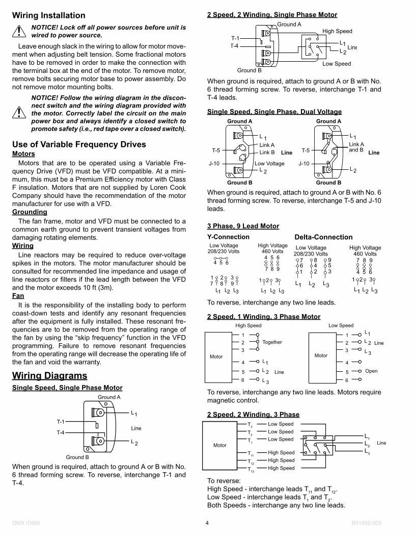
2 Speed, 2 Winding, Single Phase MotorGround A
Ground B
T-1T-4
Low Speed
High Speed
L1L2
Line
When ground is required, attach to ground A or B with No. 6 thread forming screw. To reverse, interchange T-1 and T-4 leads.
Single Speed, Single Phase, Dual Voltage
Ground B
J-10
T-5
Ground A
Link ALink B
Low Voltage
Line
L 2
L 1
Ground A
Link Aand B
L1
L2
Line
Ground B
T-5
J-10
When ground is required, attach to ground A or B with No. 6 thread forming screw. To reverse, interchange T-5 and J-10 leads.
3 Phase, 9 Lead Motor
4 5 6
17
28
39
L1 L2 L3
4 5 6
7 8 9
1 2 3
L1 L2 L3
Low Voltage208/230 Volts
High Voltage460 Volts
3 Phase, 9 Lead MotorY-Connection
7
16
7 8 9
4 5 61 2 3
Low Voltage208/230 Volts
High Voltage460 Volts
8
24
9
35
L1 L3L2L1 L3L2
3 Phase, 9 Lead MotorDelta-Connection
To reverse, interchange any two line leads.
2 Speed, 1 Winding, 3 Phase Motor
Motor
123
4
56
Together
High Speed
Line
L1L 2L 3
123
4
56
Open
Low Speed
Line
L1L 2L 3Motor
To reverse, interchange any two line leads. Motors require magnetic control.
2 Speed, 2 Winding, 3 Phase
L1T1
T2
T3Low SpeedLow SpeedLow Speed
High SpeedHigh SpeedHigh Speed
Motor
T13
T12
T11
L2Line
L3
To reverse:High Speed - interchange leads T11 and T12.Low Speed - interchange leads T1 and T2.Both Speeds - interchange any two line leads.
Wiring InstallationNOTICE! Lock off all power sources before unit is wired to power source.
Leave enough slack in the wiring to allow for motor move-ment when adjusting belt tension. Some fractional motors have to be removed in order to make the connection with the terminal box at the end of the motor. To remove motor, remove bolts securing motor base to power assembly. Do not remove motor mounting bolts.
NOTICE! Follow the wiring diagram in the discon-nect switch and the wiring diagram provided with the motor. Correctly label the circuit on the main power box and always identify a closed switch to promote safety (i.e., red tape over a closed switch).
Use of Variable Frequency DrivesMotors
Motors that are to be operated using a Variable Fre-quency Drive (VFD) must be VFD compatible. At a mini-mum, this must be a Premium Efficiency motor with Class F insulation. Motors that are not supplied by Loren Cook Company should have the recommendation of the motor manufacturer for use with a VFD.Grounding
The fan frame, motor and VFD must be connected to a common earth ground to prevent transient voltages from damaging rotating elements.Wiring
Line reactors may be required to reduce over-voltage spikes in the motors. The motor manufacturer should be consulted for recommended line impedance and usage of line reactors or filters if the lead length between the VFD and the motor exceeds 10 ft (3m).Fan
It is the responsibility of the installing body to perform coast-down tests and identify any resonant frequencies after the equipment is fully installed. These resonant fre-quencies are to be removed from the operating range of the fan by using the “skip frequency” function in the VFD programming. Failure to remove resonant frequencies from the operating range will decrease the operating life of the fan and void the warranty.
Wiring DiagramsSingle Speed, Single Phase Motor
T-1
T-4
Ground B
L 2
L1
Ground A
Line
When ground is required, attach to ground A or B with No. 6 thread forming screw. To reverse, interchange T-1 and T-4.

5QMX IO&M B51092-003
Typical Wiring Path for Roof Mounted UnitsFor sizes 135–600, route conduit under motor cover
between the motor support rails and out to enclosure as shown in Figure 1 below.
Weather Cover
Liquidtite
Size 135-600, RunLiquidtite BetweenWeather Cover and Unit
Figure 1
For sizes 90–120, route conduit through holes in the sides of the motor support saddle as shown in Figure 2 below.
Enclosure May Be Locatedin Either Corner(Liquidtite Not Shown)
90-120, RunLiquidtite ThroughHoles in Saddle
Figure 2
Wheel RotationTest the fan to ensure the rotation of the wheel is the
same as indicated by the arrow marked Rotation.115 and 230 Single Phase Motors
Fan wheel rotation is set correctly at the factory. Chang-ing the rotation of this type of motor should only be at-tempted by a qualified electrician.208, 230 and 460 3 Phase Motors
These motors are electrically reversible by switching two of the supply leads. For this reason, the rotation of the fan cannot be restricted to one direction at the factory. See Wiring Diagrams for specific information on reversing wheel direction.
NOTICE! Do not allow the fan to run in the wrong direction. This will overheat the motor and cause serious damage. For 3-phase motors, if the fan is running in the wrong direction, check the control switch. It is possible to interchange two leads at this location so that the fan is operating in the cor-rect direction.
QMX
QMX-XPCorrect Airflow
Direction
QMX-HP
NOTICE! Do not allow the fan airflow to go in the wrong direction.
Final Installation Steps1. Inspect fasteners and setscrews, particularly fan
mounting and bearing fasteners then tighten accord-ing to Recommended Torque for Setscrews/Bolts.
2. Inspect for correct voltage with a voltmeter.3. Ensure all accessories are installed.
OperationPre-Start Checks1. Lock out all the primary and secondary power sources.2. Ensure fasteners and setscrews, particularly those
used for mounting the fan, are tightened.3. Inspect belt tension and pulley alignment.4. Inspect motor wiring.5. Ensure belt touches only the pulley.6. Ensure fan and ductwork are clean and free of debris.7. Inspect wheel-to-inlet clearance. The correct wheel-
to-inlet clearance is critical to proper fan performance. 8. Close and secure all access doors.9. Restore power to fan.

6QMX IO&M B51092-003
• Inspect variable inlet vanes (if supplied) for freedom of operation and excessive wear. The vane position should agree with the position of the control arm. As the vari-able inlet vanes close, the entering air should spin in the same direction as the wheel
• Inspect springs and rubber isolators for deterioration and replace as needed
• Inspect for cleanliness. Clean exterior surfaces only. Removing dust and grease on motor housing assures proper motor cooling. Removing dirt from the wheel and housing prevents imbalance and damage
LubricationFan Bearings
QMX bearings are lubricated through a grease fitting on the exterior of the fan housing and should be lubricated by the schedule, Conditions Chart.
For best results, lubricate the bearing while the fan is in operation. Pump grease in slowly until a slight bead forms around the bearing seals. Excessive grease can burst seals thus reducing bearing life.Lubrication Conditions Chart
Fan Class Fan Status Shaft Size Maximum Interval
(operation hrs)
QMX
Normal Conditions (clean, dry & smooth)
>1-1/2” 7500<1-1/2” 2000
Extreme Conditions (dirty/wet/rough)
>1-1/2” 1500<1-1/2” 400
QMX-HP
Normal Conditions (clean, dry & smooth)
>2” 5000<2” 1000
Extreme Conditions (dirty/wet/rough)
>2” 1000<2” 200
QMX-XP
Normal Conditions (clean, dry & smooth)
>4” 2000<4” 1000
Extreme Conditions (dirty/wet/rough)
>4” 400<4” 200
In the event the bearing cannot be seen, use no more than three injections with a hand-operated grease gun.
Before lubricating, the grease nipple and immediate vicinity should be thoroughly cleaned without the use of high pressure equipment. The grease should be supplied slowly as the bearing rotates until fresh grease slips past the seal. Excessive pressure should be avoided to prevent seal damage.Exceptions to the greasing interval chart:• Periodic Applications (any break of one week or
more): It is recommended that full lubrication be per-formed prior to each break in operation
• Higher Temperature: It is recommended to halve the intervals for every 30°F increase in operating tempera-ture above 120°F not to exceed 230°F for standard bear-ings; high temperature bearings (optional) can operate up to 400°F
• Vertical Shaft: It is recommended that the intervals should be halvedLoren Cook Company uses petroleum lubricant in a lithi-
um base. Other types of grease should not be used unless the bearings and lines have been flushed clean. If another type of grease is used, it should be a lithium-based grease conforming to NLGI grade 2 consistency.
A NLGI grade 2 grease is a light viscosity, low-torque, rust-inhibiting lubricant that is water resistant. Its tempera-ture range is from -30°F to +200°F and capable of intermit-tent highs of +250°F.
Start-UpTurn on the fan. In variable speed units, set fan to its low-
est speed and inspect for the following:• Direction of rotation• Excessive vibration• Unusual noise• Bearing noise• Improper belt alignment or tension (listen for squealing)• Improper motor amperage or voltage
NOTICE! If a problem is discovered, immediately shut off the fan. Lock out all electrical power and check for the cause of the trouble. Refer to Troubleshooting.
InspectionInspection of the fan should be conducted at the first 30
minute, 8 hour and 24 hour intervals of satisfactory op-eration. During the inspections, stop the fan and inspect as per the Conditions Chart.30 Minute Interval
Inspect bolts, setscrews and motor mounting bolts. Ad-just and tighten as necessary.
8 Hour IntervalInspect belt alignment and tension. Adjust and tighten as necessary.
24 Hour IntervalInspect belt tension. Adjust and tighten as necessary.
Recommended Torque for Setscrews/Bolts (IN-LB)Setscrews Hold Down Bolts
SizeKey Hex Across Flats
Recommended Torque Size Recommended
TorqueMin. Max.#8 5/64” 15 21 3/8”-16 324#10 3/32” 27 33 1/2”-13 7801/4 1/8” 70 80 5/8”-11 1440
5/16 5/32” 140 160 3/4”-10 24003/8 3/16” 250 290 7/8”-9 19207/16 7/32” 355 405 1”-8 27001/2 1/4” 560 640 1-1/8”-7 42005/8 5/16” 1120 1280 1-1/4”-7 60003/4 3/8” 1680 1920 - -7/8 1/2” 4200 4800 - -1 9/16” 5600 6400 - -
MaintenanceEstablish a schedule for inspecting all parts of the fan.
The frequency of inspection depends on the operating conditions and location of the fan.
Inspect fans exhausting corrosive or contaminated air within the first month of operation. Fans exhausting con-taminated air (airborne abrasives) should be inspected ev-ery three months.
Regular inspections are recommended for fans exhaust-ing non-contaminated air.
It is recommended the following inspections be con-ducted twice per year:• Inspect bolts and setscrews for tightness. Tighten as
necessary• Inspect belt wear and alignment. Replace worn belts
with new belts and adjust alignment as needed. Refer to Belt and Pulley Installation, page 3
• Bearings should be inspected as recommended in the Conditions Chart
7QMX IO&M B51092-003
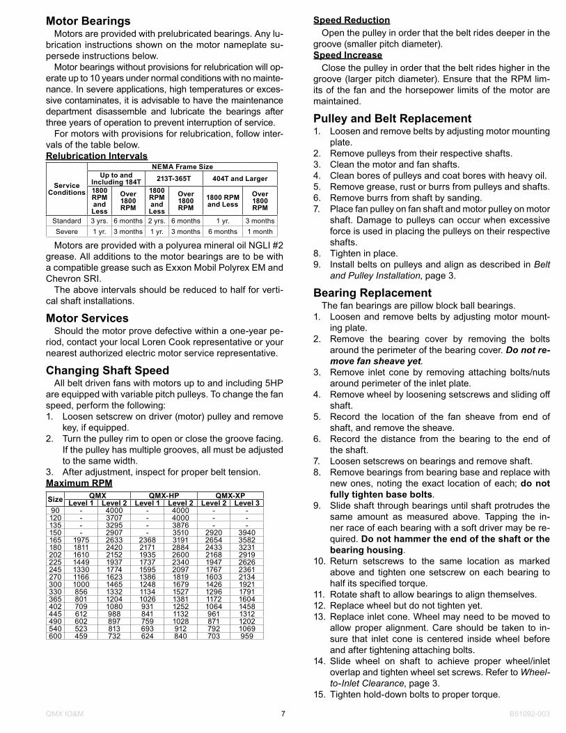
Motor BearingsMotors are provided with prelubricated bearings. Any lu-
brication instructions shown on the motor nameplate su-persede instructions below.
Motor bearings without provisions for relubrication will op-erate up to 10 years under normal conditions with no mainte-nance. In severe applications, high temperatures or exces-sive contaminates, it is advisable to have the maintenance department disassemble and lubricate the bearings after three years of operation to prevent interruption of service.
For motors with provisions for relubrication, follow inter-vals of the table below.Relubrication Intervals
Service Conditions
NEMA Frame SizeUp to and
Including 184T 213T-365T 404T and Larger1800 RPM and Less
Over 1800 RPM
1800 RPM and Less
Over 1800 RPM
1800 RPM and Less
Over 1800 RPM
Standard 3 yrs. 6 months 2 yrs. 6 months 1 yr. 3 monthsSevere 1 yr. 3 months 1 yr. 3 months 6 months 1 month
Motors are provided with a polyurea mineral oil NGLI #2 grease. All additions to the motor bearings are to be with a compatible grease such as Exxon Mobil Polyrex EM and Chevron SRI.
The above intervals should be reduced to half for verti-cal shaft installations.
Motor ServicesShould the motor prove defective within a one-year pe-
riod, contact your local Loren Cook representative or your nearest authorized electric motor service representative.
Changing Shaft SpeedAll belt driven fans with motors up to and including 5HP
are equipped with variable pitch pulleys. To change the fan speed, perform the following:1. Loosen setscrew on driver (motor) pulley and remove
key, if equipped.2. Turn the pulley rim to open or close the groove facing.
If the pulley has multiple grooves, all must be adjusted to the same width.
3. After adjustment, inspect for proper belt tension.Maximum RPMSize QMX QMX-HP QMX-XP
Level 1 Level 2 Level 1 Level 2 Level 2 Level 390 - 4000 - 4000 - -120 - 3707 - 4000 - -135 - 3295 - 3876 - -150 - 2907 - 3510 2920 3940165 1975 2633 2368 3191 2654 3582180 1811 2420 2171 2884 2433 3231202 1610 2152 1935 2600 2168 2919225 1449 1937 1737 2340 1947 2626245 1330 1774 1595 2097 1767 2361270 1166 1623 1386 1819 1603 2134300 1000 1465 1248 1679 1426 1921330 856 1332 1134 1527 1296 1791365 801 1204 1026 1381 1172 1604402 709 1080 931 1252 1064 1458445 612 988 841 1132 961 1312490 602 897 759 1028 871 1202540 523 813 693 912 792 1069600 459 732 624 840 703 959
Speed ReductionOpen the pulley in order that the belt rides deeper in the
groove (smaller pitch diameter).Speed Increase
Close the pulley in order that the belt rides higher in the groove (larger pitch diameter). Ensure that the RPM lim-its of the fan and the horsepower limits of the motor are maintained.
Pulley and Belt Replacement1. Loosen and remove belts by adjusting motor mounting
plate.2. Remove pulleys from their respective shafts.3. Clean the motor and fan shafts.4. Clean bores of pulleys and coat bores with heavy oil.5. Remove grease, rust or burrs from pulleys and shafts.6. Remove burrs from shaft by sanding.7. Place fan pulley on fan shaft and motor pulley on motor
shaft. Damage to pulleys can occur when excessive force is used in placing the pulleys on their respective shafts.
8. Tighten in place.9. Install belts on pulleys and align as described in Belt
and Pulley Installation, page 3.
Bearing ReplacementThe fan bearings are pillow block ball bearings.
1. Loosen and remove belts by adjusting motor mount-ing plate.
2. Remove the bearing cover by removing the bolts around the perimeter of the bearing cover. Do not re-move fan sheave yet.
3. Remove inlet cone by removing attaching bolts/nuts around perimeter of the inlet plate.
4. Remove wheel by loosening setscrews and sliding off shaft.
5. Record the location of the fan sheave from end of shaft, and remove the sheave.
6. Record the distance from the bearing to the end of the shaft.
7. Loosen setscrews on bearings and remove shaft.8. Remove bearings from bearing base and replace with
new ones, noting the exact location of each; do not fully tighten base bolts.
9. Slide shaft through bearings until shaft protrudes the same amount as measured above. Tapping the in-ner race of each bearing with a soft driver may be re-quired. Do not hammer the end of the shaft or the bearing housing.
10. Return setscrews to the same location as marked above and tighten one setscrew on each bearing to half its specified torque.
11. Rotate shaft to allow bearings to align themselves.12. Replace wheel but do not tighten yet.13. Replace inlet cone. Wheel may need to be moved to
allow proper alignment. Care should be taken to in-sure that inlet cone is centered inside wheel before and after tightening attaching bolts.
14. Slide wheel on shaft to achieve proper wheel/inlet overlap and tighten wheel set screws. Refer to Wheel-to-Inlet Clearance, page 3.
15. Tighten hold-down bolts to proper torque.

8QMX IO&M B51092-003
16. Turn the shaft by hand. Resistance should be the same as it was before hold-down bolts were fully tightened.
17. Tighten all bearing setscrews to full specified torque.18. Replace the sheave, align with motor sheave and ad-
just the belt tension.19. Test run fan and retighten all setscrews and bolts and
trim balance as necessary. (0.0785 in/sec max).20. Replace discharge cover.Wheel Replacement
The wheel has a pre-machined shoulder in the hub for the use of most two and three jaw mechanical pullers.1. Align center of the puller with the center of the shaft.2. Ensure all setscrews in the hub, normally two, are fully
removed.3. Slowly remove wheel from the shaft.
TroubleshootingProblem and Potential CauseLow Capacity or Pressure: • Incorrect direction of rotation. Make sure the fan rotates
in same direction as the arrows on the motor or belt drive assembly
• Poor fan inlet conditions. There should be a straight clear duct at the inlet or outlet
• Improper wheel alignment• Fan backwards. Refer to airflow diagram on page 5
Excessive Vibration and Noise: • Damaged wheel• Belts misaligned• Belts too loose; worn or oily belts• Loose fasteners• Speed too high• Incorrect direction of rotation. Make sure the fan rotates
in same direction as the arrows on the motor or belt drive assembly
• Bearing setscrews loose• Bearings need lubrication or replacement• Debris in impeller• Fan surge• See page 4 for issues regarding use of VFD
Overheated Motor: • Motor improperly wired• Incorrect direction of rotation. Make sure the fan rotates
in same direction as the arrows on the motor or belt drive assembly
• Cooling air diverted or blocked• Improper inlet clearance• Incorrect fan speed• Incorrect voltage
Overheated Bearings: • Improper bearing lubrication• Excessive belt tension
SEE DETAIL A
PRE-MACHINED SHOULDER
DETAIL A
9QMX IO&M B51092-003
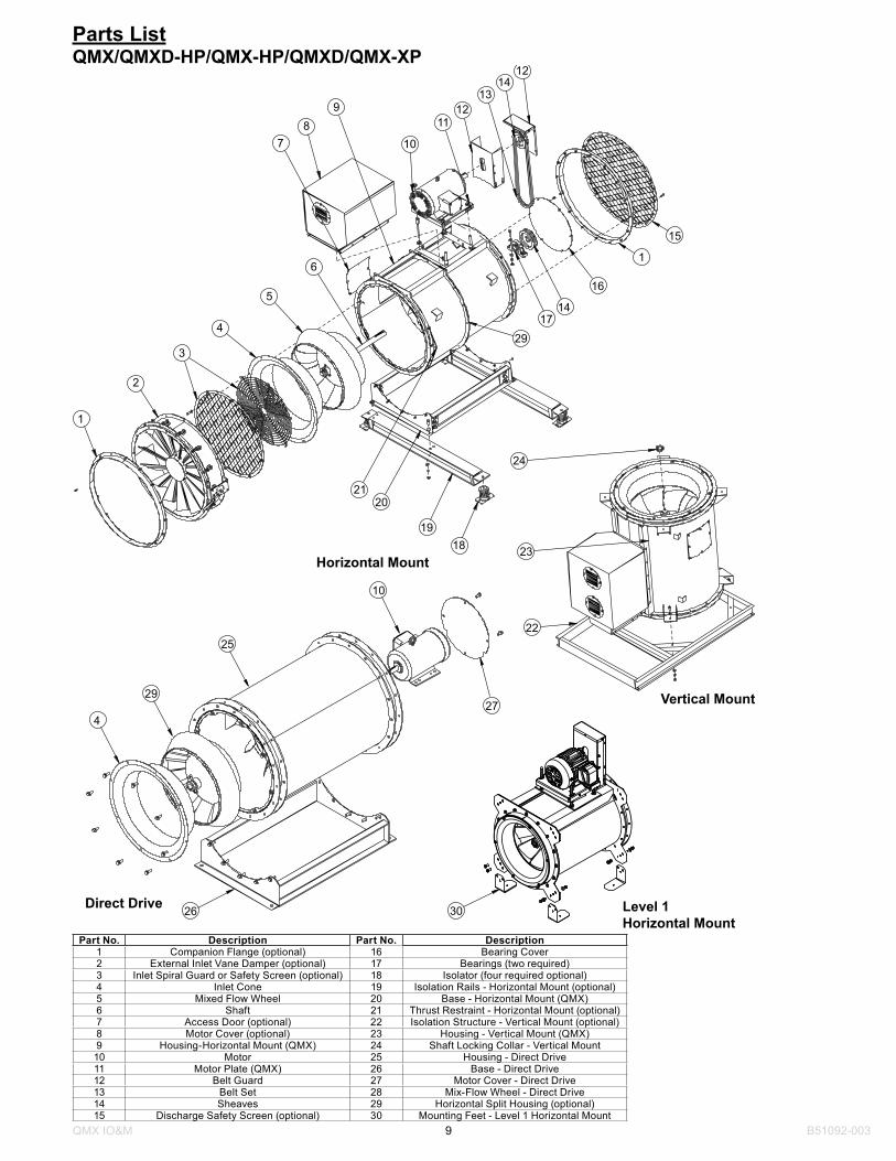
Parts ListQMX/QMXD-HP/QMX-HP/QMXD/QMX-XP
15
1
16
1417
29
1819
2021
1
2
3
4
5
6
78
9
10
1112
1314
12
22
23
24
Vertical Mount4
29
25
10
26 30
27
Horizontal Mount
Direct Drive Level 1Horizontal Mount
Part No. Description Part No. Description1 Companion Flange (optional) 16 Bearing Cover2 External Inlet Vane Damper (optional) 17 Bearings (two required)3 Inlet Spiral Guard or Safety Screen (optional) 18 Isolator (four required optional)4 Inlet Cone 19 Isolation Rails - Horizontal Mount (optional)5 Mixed Flow Wheel 20 Base - Horizontal Mount (QMX)6 Shaft 21 Thrust Restraint - Horizontal Mount (optional)7 Access Door (optional) 22 Isolation Structure - Vertical Mount (optional)8 Motor Cover (optional) 23 Housing - Vertical Mount (QMX)9 Housing-Horizontal Mount (QMX) 24 Shaft Locking Collar - Vertical Mount10 Motor 25 Housing - Direct Drive11 Motor Plate (QMX) 26 Base - Direct Drive12 Belt Guard 27 Motor Cover - Direct Drive13 Belt Set 28 Mix-Flow Wheel - Direct Drive14 Sheaves 29 Horizontal Split Housing (optional)15 Discharge Safety Screen (optional) 30 Mounting Feet - Level 1 Horizontal Mount
10QMX IO&M B51092-003
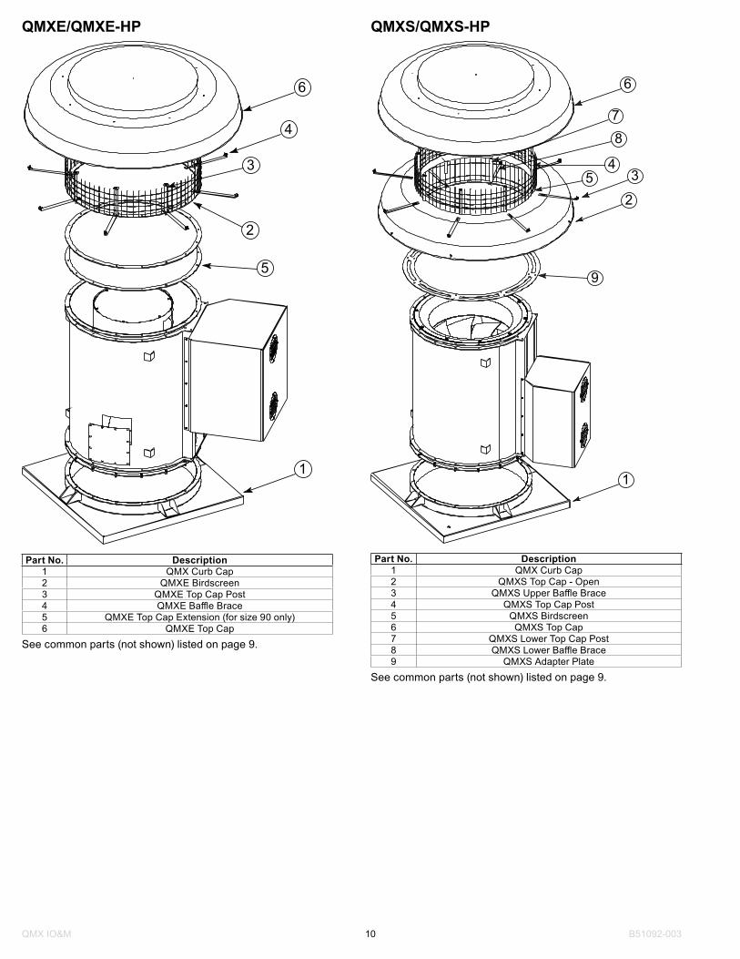
QMXE/QMXE-HP
1
2
3
4
5
6
Part No. Description1 QMX Curb Cap2 QMXE Birdscreen3 QMXE Top Cap Post4 QMXE Baffle Brace5 QMXE Top Cap Extension (for size 90 only)6 QMXE Top Cap
See common parts (not shown) listed on page 9.
QMXS/QMXS-HP
1
2
34
5
6
7
8
9
Part No. Description1 QMX Curb Cap2 QMXS Top Cap - Open3 QMXS Upper Baffle Brace4 QMXS Top Cap Post5 QMXS Birdscreen6 QMXS Top Cap7 QMXS Lower Top Cap Post8 QMXS Lower Baffle Brace9 QMXS Adapter Plate
See common parts (not shown) listed on page 9.

11QMX IO&M B51092-003
QMXU/QMXU-HP
5
4
2
1
3
6
Part No. Description1 QMX Curb Cap2 QMXU Lifting Lug3 QMXU Damper4 QMXU Damper Stop5 QMXU Windband6 QMXU Discharge Guard (optional)
See common parts (not shown) listed on page 9.
QMXLE/QMXLE-HP
1
2
3
4
5
6
7
Part No. Description1 QMXLE Mixing Box2 QMXLE Curb Cap3 QMXLE Middle Section4 QMXLE Adapter Plate5 QMXLE Stack Damper6 QMXLE Windband7 QMXLE Lifting Lug
See common parts (not shown) listed on page 9.
12QMX IO&M B51092-003
Limited WarrantyLoren Cook Company warrants that your Loren Cook fan was manufactured free of defects in materials and workmanship, to the extent stated herein.
For a period of one (1) year after date of shipment, we will replace any parts found to be defective without charge, except for shipping costs which will be paid by you. This warranty is granted only to the original purchaser placing the fan in service. This warranty is void if the fan or any part thereof has been altered or modified from its original design or has been abused, misused, damaged or is in worn condition or if the fan has been used other than for the uses described in the company manual. This warranty does not cover defects resulting from normal wear and tear. To make a warranty claim, notify Loren Cook Company, General Offices, 2015 East Dale Street, Springfield, Missouri 65803-4637, explaining in writing, in detail, your complaint and referring to the specific model and serial numbers of your fan. Upon receipt by Loren Cook Company of your written complaint, you will be notified, within thirty (30) days of our receipt of your complaint, in writing, as to the manner in which your claim will be handled. If you are entitled to warranty relief, a warranty ad-justment will be completed within sixty (60) business days of the receipt of your written complaint by Loren Cook Company. This warranty gives only the original purchaser placing the fan in service specifically the right. You may have other legal rights which vary from state to state. For fans provided with motors, the motor manufacturer warrants motors for a designated period stated in the manufacturer’s warranty. Warranty periods vary from manufacturer to manufacturer. Should motors furnished by Loren Cook Company prove defective during the designated period, they should be returned to the nearest authorized motor service station. Loren Cook Company will not be responsible for any removal or installation costs.
Corporate Offices: 2015 E. Dale St. Springfield, MO 65803Phone 417-869-6474 | Fax 417-862-3820 | lorencook.com
September 2017
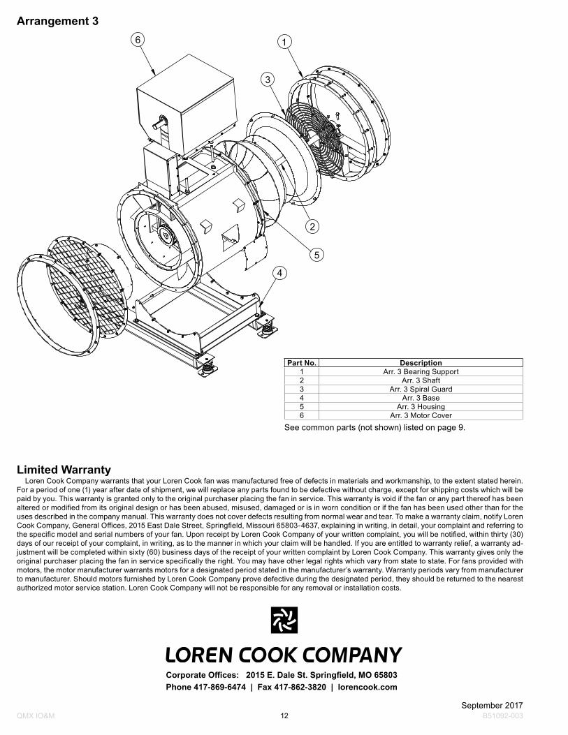
Arrangement 31
2
3
4
5
6
Part No. Description1 Arr. 3 Bearing Support2 Arr. 3 Shaft3 Arr. 3 Spiral Guard4 Arr. 3 Base5 Arr. 3 Housing6 Arr. 3 Motor Cover
See common parts (not shown) listed on page 9.