
QLS 301 Lubrication System - lincolndrives.com 301 Lubrication System 2.1A-380006-A99 April 1999...
24
QLS 301 Lubrication System 2.1A-380006-A99 April 1999 Form 402865 Section - Q3 Page - 9 QLS 301 Installation and Operation Instructions 4197a99 810-55230-1
Transcript of QLS 301 Lubrication System - lincolndrives.com 301 Lubrication System 2.1A-380006-A99 April 1999...

QLS 301 Lubrication System
2.1A-380006-A99 April 1999 Form 402865 Section - Q3 Page - 9
QLS 301Installation and Operation Instructions
4197a99
810-55230-1

Page Number 2 of 24
QLS 301
Sub
ject
to
mod
ifica
tions
2.1B-38006-A99 Form 402865
Installation and Operation Instructions
Table of Contents
Safety Instructions ...................................................... 2Installation Instructions ............................................... 3Pump ............................................................................ 3SSV Divider Block ......................................................... 3Crossporting of the SSV Divider Block ......................... 3Check valves ................................................................. 4Feedback of supplied lubricant .................................... 4Installing Zerk-Locks onto grease fittings ................... 4Connecting Feed Lines ................................................ 5
Filling of reservoir .................................................... 5Setting of lubrication cycle time intervall ................ 5
Electrical Connection Diagrams .................................. 6QLS 301Selection Guide .............................................. 7Description of QLS 301 ............................................... 8Operating of QLS 301 .................................................. 8Pressure relief valve ..................................................... 9Pump Display Window ................................................. 9Monitoring time/malfunction ......................................... 9
Acknowledging the malfunction............................ 10Low-level control ................................................... 10Acknowledging the low level indication................ 10Malfunction/low level indication ............................ 10
Monitoring relay ........................................................... 10Metering of the lubricant ............................................. 10Setting and operationof the QLS 301 ............................................................ 11Display mode .............................................................. 11Operating mode .......................................................... 12Programming mode ................................................... 13Maintenance, Repair and Test .................................. 14Maintenace .................................................................. 14
Refilling reservoir .................................................. 14Repair .......................................................................... 14Functional Test ............................................................ 14Troubleshooting ......................................................... 15Technical Data ............................................................ 17Dimensions ................................................................ 18Service Part of the QLS 301 ...................................... 19Manufacturer’s declaration ......................................... 24
Safety InstructionsAppropriate Use• Use QLS 301 only for the delivery of lubricants. The pump
is designed for intermittent operation. QLS 301 is desi-gned of supplying lubricant to a maximum of 18 lubepoints per cycle .
• Do not use QLS 301 with SSV block in bottom mountingposition for mobile applications . Don’t install the pumpin areas exposed to shock.
General safety Instructions• Do not over pressurize reservoir when filling the pump.
Refill QLS 301 pump with clean lubricant.• Incorrect use may result in bearing damage caused by
poor or over-lubrication.• Each outlet used must be equipped with an appropriate
check valve see page 4, Fig.3.• Unauthorized modifications or changes to an installed
system are not recommended and will void warranty. Anymodifications must be subject to prior consultation withthe manufacturer of the QLS 301.
Regulations for prevention of accidents• To prevent accidents, observe all city, state and federal
safety regulation of the country in which the product willbe used.
For pumps with 120 VAC and 230 VAC, switch off the powersupply before beginning maintenance or repair work.
• QLS 301 operates automatically. However, a regularcheck (approximately every 2 weeks) should be made toensure that lubricant is being dispensed from all lubricantpoints.
• Used or contaminated lubricants must be disposed of inaccordance with local environmental regulations, seetechnical data sheets of lubricants.
• The manufacturer of the centralized lubrication systemwill not accept any liability for:
- damage due to the use of greases which are not or areonly conditionally pumpable in centralized lubricationsystems.
- damage caused by insufficient lubricant and irregularrefilling of pump.
- damage caused by the use of contaminated lubricants.- damage caused by inadequate disposal of used or
contaminated lubricants.- damage caused by unauthorized modification of system
componenets.- damage caused by the use of unapproved parts (voids
the pump warrenty).
Operation, Repair and Maintenace• Repairs should only be performed by authorized
personnel who are familliar with the instructions.
Explanation of symbols:� = explanation* = describes and action- = listing within a section
• QLS 301 must only operate with mounted or connectedSSV divider blocks.
• Pump must be regularly refilled with clean lubricant.

Sub
ject
to
mod
ifica
tions
Page Number 3 of 242.1B-38006-A99
QLS 301
Form 402865
Installation and Operation Instructions
Installation• Do not remove, modify or alter any safety equipment
already installed on the machine.• QLS 301 pump must be kept away from the sources of
heat (see Operating Temperature Specification).• Follow installation instructions of the OEM regarding
minimum distances between the drilled holes andwelding procedures.
• Use following recommendations to select an installationlocation:
- Keep the feed lines as short as possible.- Provide access to fill, clean and visually monitor the
pump operation.• Installing QLS 301 pump with the reservoir upright is
perferred, but pump may be installed with the reservoir inhorizontal without affecting its operation.
• The QLS 301 may only be installed by qualified person-nel. The connection (N/L/PE) of the supply voltage mustbe made according to VDE 0100 and VDE 0160.
• Install a protective and lock out device for isolating anddisconnecting the QLS 301. Before beginning the instal-lation work, disconnect the electrical supply .
• Failure to observe the safety instructions, e. g. touchingelectrically charged parts when the system is opened, orimproper handling of the QLS 301 may cause seriousinjury or death .
• If the values specified in the Technical Data are excee-ded, the device may overheat. It may damage the QLS301 and thus impair the electric safety.
Installation InstructionsPump
• Use drilling template to mark and drill mounting holes ofthe QLS 301. Drilling template and mounting bolts areincluded in the package.
SSV Divider Block Crossporting of the SSV divider blocks
• The outlets of the SSV divider block can be combined toincrease the amount of lubricant for a particular outlet. Todo this, simply plug the unused outlets with the closureplug (see Fig. 2), provided in the accessory kit.
• Lubricant from a plugged outlet is redirected to the nextoutlet on the same side of the SSV divider block indescending numerical order (see Fig.1). For instanceplugging outlets 5 and 3 will triple the amount of lubricantat outlet 1.
• Do not plug outlet numbers 1 and 2 on SSV 8, 12 and 18of pump models with SSV divider block installed on thebottom.
Fig.1 - Single double and tripple lubricant output
x -Outlet quantity (single, double, etc.)1... 10 Outlet numbersA - Clamping ring (brass)
4163a98
Fig. 2 - Closure plug, provided in the accessory kits
* Install a closure plug in each outlet port hole which is notrequired, see Fig. 1 or 4.
1014a99

Page Number 4 of 24
QLS 301
Sub
ject
to
mod
ifica
tions
2.1B-38006-A99 Form 402865
Installation and Operation Instructions
Installing Zerk-Locks onto grease fittings ( for inch sizeaccessory kits only)• The Zerk-Lock fitting consists of the Zerk-Lock body,
insert and a Quicklinc fitting.* Place the Zerk-Lock body over the grease fitting and place
the staking tool firmly against the Zerk-Lock insert.(Staking tool is included in the accessory kits, see page8).
* Strike the tool sharply with a hammer until the Zerk-Lockinsert partially crimps onto the grease fitting.
Fig. 5 - Place the Zerk-Lockbody over the grease fitting
Direct (internal) feedback feature
• All pumps with the back mouted SSV divider block ,starting from serial No. 998000100C/001 are assembledwith outlet 2 plugged for direct feedback capability. Tochange the outlet 2 for bearing lubrication, replaceclosure plug with check valve (Fig. 3).
• On all pumps with previous serial numbers, never closeoutlet 1.
Fig. 4 - Internal feedback of supplied lubricant, only on back-side mounted SSV divider blocks
Check valves
* Install one complete check valve in each outlet port holewhich will be used, see Fig. 1 and 4.
* For feedlines (dia. 6x1.5 mm, 1/4“ I.D., provided in theaccessory kits) use check valves with standard collar andknurled flange.
Fig. 3 -Check valve, push-in type
4180a99
x -Outlet quantity (single, A - Clamping ring (brass)double, etc.) R - Return line borehole1... 10 Outlet numbers
Fig. 6 - Installation of Zerk-Locks with staking tool
4201a99
4188b99
Note: To feed back unneeded lubricant quantities from bot-tom - side mounted divider block to the reservoir, connectunneeded outlet via feedline to plug 5 (Fig. 14) for externalreturn line.
Lubrication points
Installing Quicklinc fittings into lube points(for metric size accessory kits only)
* Remove hydraulic lube fittings from lube points andinstall appropriate Quicklinc-fittings into the bore holes ofthe lube points.
4200a99
• All pumps with the back mouted SSV divider block ,starting from serial No. 998000100C/001 have thecabability to feed back unused lubricant from closedoutlets directly to the reservoir internally (see R Fig. 4).
Note: The pumps with previous serial numbers have capabi-lity to feed back the lubricant directly to the reservoir onlyfrom even outlets. For instance on a SSV 6 devider block, theoutlets 2, 4, 6 are closed.* To achieve this the outlet 2 should be closed with a
closure plug (see Fig. 2). For instance (see Fig. 4) thelubricant from outlets 1, 2 and 4 will be internally feedback to the reservoir, outlet 3 will have double amountand outlet 6 will have single amout of lubricant.

Sub
ject
to
mod
ifica
tions
Page Number 5 of 242.1B-38006-A99
QLS 301
Form 402865
Installation and Operation Instructions
* Screw the Quicklinc fitting into the Zerk-Lock body andtighten until parts resist further tightening, (about 1-1/2turns).
• If the lines are not primed, prime all lubrication feed linesbefore connecting them to the Zerk-Locks.
• Connect feed lines (dia. 6x1.5 mm, 1/4’’) from the checkvalves directly to existing grease fittings using the Zerk-Lock fittings included with the accessory kit.
Note: Push the end of the line firmly into the Quicklinc fittinguntil it is fully seated in the body. The primed feed lines aremarked with white lines (Fig.8, 9) as an installation aid.
Fig. 7 - Screwing Quicklinc fitting into the Zerk-Lock body
Note: Quicklinc hex. is 12 mm. Zerk-Lock body hex is 1/2 ’’.
* Move the Zerk-Lock and tube fitting from side to side onthe grease fitting to insure the Zerk-Lock is firmly seated.
Fig. 9 - Feed line insert into the fitting up to the next white mark
4157a98
• Cut the pressure plastic tube off at one of the white linesbefore it is mounted. Then insert the plastic pressuretube into the fitting up to the next white mark. This willensure a correct installation of the pressure plastic tubein the threaded tube fitting.
Connection of Feed Lines• Measure, cut and route the feedlines included in the kit.
Avoid sharp bends of the plastic tubing and the movingparts of the machine that could damage the lubricationlines. Minimum bending radius is 50 mm(2 in).
• Secure the lubrication lines to the machine using nylonties, clamps or straps provided in the accessory kit.
Fig. 8 Feed line installed in the Quicklinc fitting
* Cut the fed line off at one of the white lines before it ismounted.
* Then insert the feed line into the fitting up to the nextwhite mark.
• This will ensure a correct installation of the feed line inthe tube fitting.
Filling of reservoir
* Fill the reservoir with clean suitable lubricant.
* Expel all air from under follow plate. Make sure that thefollower plate seal moves above the vent hole to ensurethat all air pockets are vented.
Fig. 10 - Vent hole on reservoir4204a99
Setting of lubrication cycle time interval* Set the lubrication cycle time interval (see page 13).
4203a99
4202a99

Page Number 6 of 24
QLS 301
Sub
ject
to
mod
ifica
tions
2.1B-38006-A99 Form 402865
Installation and Operation Instructions
Electrical Connecting Diagrams
Direct current (VDC)
Alternate current (VAC)
Electrical connection• Before starting, make sure that the electrical supply is off.
The device may not be connected or disconnected whenthe power is on. The protective conductor must always beconnected. Take care that this line section is undamagedand conforms to standards and the contacts are safe.
* Connect the electric wires according. to the followingelectrical connecting diagrams.
Note: The protection IP6K9K (NEMA 4) is guaranteed whenthe socket (x1, x2) is tightened on housing cover with flatpacking.
Fig. 11 - Electrical Connecting Diagram, direct current.
4192a99
Fig. 12 - Electrical Connecting Diagram, alternate current.
4191a99

Sub
ject
to
mod
ifica
tions
Page Number 7 of 242.1B-38006-A99
QLS 301
Form 402865
Installation and Operation Instructions
Pump modelsExamples of part numbers P30100810111
P30162410151P301 6 2 4 1 0 1 5 1
PumpFor grease..............................................P301
SSV Divider BlockExternal, SSV 6, SSV 8**.................................0External, SSV 12, SSV 18**.............................1SSV 6 (back)...................................................3SSV 8 (bottom)................................................4SSV 12............................................................6SSV 18............................................................9
SSV Divider Block PositionNone.................................................................0Back.................................................................1Bottom1.............................................................2
Operating Voltage12 VDC.............................................................224 VDC.............................................................4120 VAC*..........................................................6230 VAC*..........................................................8
Reservoir/Low level control1 l reservoir with low level control....................1
Dry ContactsNone...................................................................0Yes.....................................................................1
Type of Plug ConnectorSquare-type, acc. to DIN 43650 typeof construction A................................................1
Electrical ConnectorsWithout socket, without cable.............................0With socket, without cable*................................1With socket, with cable, 10 m.............................5With socket, with ADR cable, 10 m.....................6
Control p. c. b.None....................................................................0Monitored, 1cycle, SSV 12, SSV 18Monitored, 1, 2, 3 cycles, SSV 6, SSV 8.............1
Example of an explained model number:Pump model P30131810111 -Grease pump, SSV 6 block mounted on the back, 230 VAC, with low level and without dry contact.
* Note: 1. Standard 12 and 24 VDC pump models are shipped with 10 meter (30’) electrical cable.2. Standard 120 and 230 VAC pump models are shipped without electrical cable (electrical connection 1 only)
** Note: For external divider block application only use the specific divider blocks SSV ... KNQLS.On pump models without divider block there is not possible to close cycles without changes on the p. c. b.
1 Note: Do not use QLS 301 with SSV block in bottom mounting position for mobile applications. Don�t installthe pump in areas exposed to shock.
Accessory KitsInch Size Kits: Metric Size Kits:SSV 6/8 part no. 550-36971-1 SSV 6/8 part no. 550-36970-1***SSV 12 part no. 550-36971-2 SSV 12 part no. 550-36970-2 ***SSV 18 part no. 550-36971-3 SSV 18 part no. 550-36970-3 ***
*** Lube fittings must be ordered separately
QLS 301 Selection Guide
Page Number 8 of 24
QLS 301
Sub
ject
to
mod
ifica
tions
2.1B-38006-A99 Form 402865
Installation and Operation Instructions
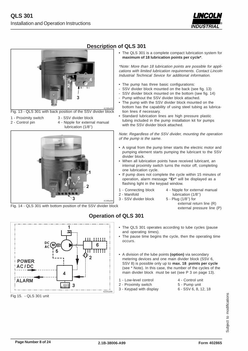
Description of QLS 301• The QLS 301 is a complete compact lubrication system for
maximum of 18 lubrication points per cycle* .
*Note: More than 18 lubrication points are possible for appli-cations with limited lubrication requirements. Contact LincolnIndustrial Technical Sevice for additional information.
• The pump has three basic configurations:- SSV divider block mounted on the back (see fig. 13)- SSV divider block mounted on the bottom (see fig. 14)- Pump without the SSV divider block attached.• The pump with the SSV divider block mounted on the
bottom has the capability of using steel tubing as lubrica-tion lines if necessary.
• Standard lubrication lines are high pressure plastictubing included in the pump installation kit for pumpswith the SSV divider block attached.
Note: Regardless of the SSV divider, mounting the operationof the pump is the same.
• A signal from the pump timer starts the electric motor andpumping element starts pumping the lubricant to the SSVdivider block.
• When all lubrication points have received lubricant, aninternal proximity switch turns the motor off, completingone lubrication cycle.
• If pump does not complete the cycle within 15 minutes ofoperation, alarm message “Er“ will be displayed as aflashing light in the keypad window.
Fig. 13 - QLS 301 with back position of the SSV divider block
Fig 15. - QLS 301 unit
Operation of QLS 301
Fig. 14 - QLS 301 with bottom position of the SSV divider block
• The QLS 301 operates according to lube cycles (pauseand operating times).
• The pause time begins the cycle, then the operating timeoccurs.
• A division of the lube points (option) via secondarymetering devices and one main divider block (SSV 6,SSV 8) is possible only up to max. 18 points per cycle(see * Note). In this case, the number of the cycles of themain divider block must be set (see P 3 on page 13).
4198a99
1 - Proximity switch 3 - SSV divider block2 - Control pin 4 - Nipple for external manual
lubrication (1/8’’)
4199a99
1 - Connecting block 4 - Nipple for external manual2 - Manifold lubrication (1/8’’)3 - SSV divider block 5 - Plug (1/8’’) for
external return line (R)external pressure line (P)
1 - Low-level control 4 - Control unit2 - Proximity switch 5 - Pump unit3 - Keypad with display 6 - SSV 6, 8, 12, 18
4205a99

Sub
ject
to
mod
ifica
tions
Page Number 9 of 242.1B-38006-A99
QLS 301
Form 402865
Installation and Operation Instructions
Pressure relief valve
Fig. 16 - Pressure relief valve (cartridge) in housing
• The QLS 301 is protected with a pressure relief valve(cartridge).
• The pressure relief valve limits the pressure build-up inthe QLS 301. It opens at an overpressure of 201 bar(3000 psi).
• If the pressure relief valve is actuated, this indicates thatthe system is malfunctioning. The lubricant flows backinto the reservoir (not visible).
• Upon expiration of the monitoring time of 15 minutes, thepump switches off. The fault indication ”Er” is displayedon the key pad of the pump. See ”Display mode” under”Control unit”.
Pump Display Window
• Pump “On” is indicated on the display by an illuminateddecimal point (pause time) (fig. 17).
• Pump “running” is indicated on the display by a rotatinglight movement of the green display (operating time)(fig.18).
• If the voltage supply is interrupted during the operatingtime, the operating time starts again from the beginningafter switching on.
Fig. 18 - Green display (operating time)
Fig. 17 - Green decimal point (pause time)
• Additional lube cycle (Manual Lube)- is initiated via the button (Fig. 19). Press the button for 2
seconds.- can be initiated at any time, provided that the power
supply is applied.Note: If a malfunction is present (flashing display), first ack-nowledge this malfunction.• If a fault signal (malfunction) is present, it will be cancel-
led after the system is operating properly.
Monitoring time/malfunction
Fig. 19 - Pushbutton for additional lubrication cycle
Fig. 20 - Display of a fault indication
4208a999
4209a99
4222a99
4210a99
4196a99
• If the cycle is not complete within 15 minutes (monitoringtime) after expiration of the pause time, the pump imme-dately switches off.
• The fault indication “ Er ” (error) is displayed as aflashing light (fig. 20). At the same time, a potential freecontact is available for the external fault indication (opti-on).
• If a malfunction is present, the pump no longer switcheson automatically.

Page Number 10 of 24
QLS 301
Sub
ject
to
mod
ifica
tions
2.1B-38006-A99 Form 402865
Installation and Operation Instructions
• The metering of the lubricant occurs via the integrateddivider block (e. g. SSV 8, SSV 12 or SSV 18).
• When the reservoir is nearly empty the pump displayshows “LL” (low level) .
• The follower plate (3) (Fig. 24) of the reservoir moves thepin (2) with the magnet (3) ahead of the sensor on theprinted circuit board and initiates the low level signal.
• In this case, the pump is not switched off immediately.The current lube cycle is completed. Upon expiration ofthe pause time, the pump cannot be started againautomatically. The flashing display “LL” is indicated.
• Before filling the reservoir, press the button Fig. 21 foracknowledging the low level indication.
• As soon as the lubricant reservoir is filled up, the “LL”display is cancelled. The lube cycle resumes.
Acknowledging the low level indication* By pressing the button (Fig.22), the flashing display “LL”
is changed into a continuous light.
Malfunction/low level indication• If both indications occur at the same time, then both
displays “Er” and “LL” will flash.
Fig. 21 - Keypad with showing a malfunction
Fig. 22 - Acknowledging the malfunction
Fig. 23 - Display of a low-level control
Fig. 24 - Parts of low level control1 - Magnet 3 - Follower plate2 - Pin
Metering of the lubricant
• In this case, switch on the pump by pressing the buttonfor additional lube cycle, see Fig. 18. Acknowledge themalfunction before doing so.
• When a malfunction is present, it can only be cancelledby initiating an additional lube cycle and after a properlube cycle has been executed afterward.
• If the fault is still present after an additional lube cyclehas been initiated, the fault indication “Er” is displayedagain.
• The monitoring time starts at the same time as theoperating time. It is a fixed time of 15 minutes.
• If the voltage supply is interrupted during the monitoringphase (operating time), the monitoring time starts fromthe beginning after the pump is switched on again.
Acknowledging the malfunction• On pressing the button (Fig.22 ), the flashing display “Er”
changes into a continuous light.
Monitoring relay• The monitoring relay signals a low level condition or a
malfunction. In both cases, the monitoring relay will pickup. The signal is available via a potential free contact.The monitoring relay is released upon acknowledgementof the fault. The flashing indication switches to conti-nuous indication.
Models with Low-level control
4228a99
4214a99
4211a99
4229a99
4230a99
Fig. 25 -Bottom mounting position of divider block

Sub
ject
to
mod
ifica
tions
Page Number 11 of 242.1B-38006-A99
QLS 301
Form 402865
Installation and Operation Instructions
• As soon as voltage is applied to the pump, the key padis automatically in ”display mode” . The right-handdecimal point is illuminated on the display.
• Normally, the display is dark. Only the functions (deci-mal point, rotating segment display) or malfunctions (Er,LL) are displayed.
• In the display mode- The user receives information on functions and mal-
functions.
- A test display is made when the voltage is applied, allsegments and decimal points are illuminated for 2seconds.
Note: If *EP* is displayed after the display test, this indicatesthat the button or the key pad is defective.
- The right-hand decimal point (On/h) indicates theavailable voltage supply during the pause time. As soonas another message is displayed, the decimal pointturns off.
- The operating time is displayed as a rotating segment.
- “Er” is shown to indicate a malfunction
- “LL” is shown to indicate low level (where applicable)
- The flashing display is changed into a continuous lightby pressing the button (acknowledging). To acknow-ledge , press the button only briefly.
• Messages which have been acknowledged but have notyet been remedied flash again after the pump is swit-ched off and on again.
Setting and operation of the QLS 301
• Three possible modes of operation and settings can beselected at the key pad:
- Display mode- Operating mode- Programming mode
Display mode
Fig. 26 - Display in display mode
4206a99
4207a99 4227a99
4208a99
4209a99
4210a99 4211a99
4212a99 4213a99
4214a99

Page Number 12 of 24
QLS 301
Sub
ject
to
mod
ifica
tions
2.1B-38006-A99 Form 402865
Installation and Operation Instructions
Operating mode
Important :The operating mode is accessible only duringthe pause time, and cannot be operated during the runningtime (pump operating time).
• Precondition: when the voltage supply is applied, thedecimal point On/h is lit.
Operating option: initiating an additional lube cycle* Press the button. The elapsed pause time is reset. The
operating time starts. A rotating segment is visible onthe display during the whole operation time.
Operating option: read information on how to set thepause time and remaining pause time.
* Press the button.
Note: The following display sequence is shown twice and iscancelled after 60 seconds. The change of display occursevery two seconds. Example:
PP = 12h 30minrP = 5 h 10 min“PP” (set pause time)12 . (hours)
. 30 (minutes)
“rP” (remain pause time)
5 . (hours)
. 10 (minutes)
occurs after second sequence.
Display press
after 2 sec.
after 2 sec.
after 2 sec.
after 2 sec.
after 2 sec.
after 60 sec.
Fig. 27 - Display in operating mode
4208a99
4209a99
³ 2 sec
4208a99
³ 2 sec4223a99
4216a99
4220a99
4224a99
4225a99
4216a99
4208a99
4222a99
4214a99

Sub
ject
to
mod
ifica
tions
Page Number 13 of 242.1B-38006-A99
QLS 301
Form 402865
Installation and Operation Instructions
Programming mode
Setting number of cycles P3 (Option)
Important: Settings are only possible in connection withprogressive divider block SSV 6 or SSV 8 (connected asa main divider block).
* Press the button. The selection of “P3” (cycles) isdisplayed.
* Factory setting.......................................................1 cycle* Max........................................................................3 cycles* Press the button and program the number of cycles (2,
3) in accordance with the desired dosage.
Completing the programming
* Press the button. “P-” is displayed.
* There are two ways to complete the programming:- by pressing the button,
or
- if the button is not pressed within 30 seconds, pro-gramming mode is closed automatically.
Display press press
Fig. 28 - Display in programming mode
Programming options - Pause time:P1 0 – 99 hoursP2 0 – 59 minutesMin. pause time 20 minutesMax. pause time 99 hours 59 minutes
Setting hours P1* Settings are made in one direction: 0, 1, 2, 3, ..... 99 h
Button pressed once.......................increases by 1 hourButton pressed continuously................quick sequenceThe fields ‘’hour’’and ‘’minutes’’are indicated by adecimal point on the right - hand for the hours and onthe left - hand for the minutes.
Setting minutes P2* Settings are made in one direction: 0, 1, 2, 3....59
minutesButton pressed once.......................increases by 1 minuteButton pressed continuously....................quick sequence
Note: The minimum pause time begins with 20 minutes.When pause times < 20 minutes are programmed, the dis-play automatically shows .20.
* To access to the programming mode, press both but-tons at the same time ³ 4 seconds.
³ 4 sec ³ 4 sec4215a994222a99 4214a99
4222a99
4216a99
4217a99
4222a99
4214a99
4214a99
4214a99
4222a99
4222a99
4220a99
4218a99
4219a99
4221a99
4208a99

Page Number 14 of 24
QLS 301
Sub
ject
to
mod
ifica
tions
2.1B-38006-A99 Form 402865
Installation and Operation Instructions
Maintenance
To fill reservoir
Fig.29 - Filling nipple for filling reservoir
Repair
Functional Test
Fig. 30 - Push button for an additional lubrication cycle
Maintenance, Repair and Tests
• Maintenance is essentially limited to refilling the reservoirwith clean lubricant as necessary. However, checkregularly whether the lubricant is being dispensed to allthe lubrication points.
• Also check the feed lines for damage and replace them, ifnecessary.
Switch off the voltage supply for pumps 120 VAC and 230VAC before servicing the pump.
• For repair work on the QLS 301 use only Lincoln Industri-al original spare parts.
• Using non-Lincoln Industrial parts will void the pumpwarranty.
Turn off the voltage supply for pumps 120 VAC and 230 VACbefore servicing the pump.
Important: To clean the system use petroleum spirit or petro-leum. Do not use Tri, Per or similar solvents or polar ororganic solvents such as alcohol, methanol, acetone, etc.
Note: Whenever work is performed on the centralized lubri-cation system, special attention should be paid to cleanli-ness. Dirt will cause failure of the system.
• Fill the reservoir up to the ”Max.” mark via the filling nipple
Important! The grease must be free from impurities andmust not be liable to change its consistency over the courseof time.
Note: If the reservoir has been completely emptied, the pumpmay require priming and a longer running time to reach thefull lubricant output. Therefore, initate additional lube cyclesmanually.
* Press push button to initiate alubrication cycle.
Filling of the empty reservoir
• Make sure, that all air has been expelled from under thefollower plate after refilling the empty reservoir.
* The follower plate seal should clear the hole located onthe top of the reservoir. Small amount of grease shouldbe expelled to ensure expelling of air from under thefollower plate.
1 - Filling nipple 3 - Follower plate2 - Vent hole
4222a99
4231a99
* By operating the drive motor without the reservoir instal-led, there is a risk of injury by eccentric gear.

Sub
ject
to
mod
ifica
tions
Page Number 15 of 242.1B-38006-A99
QLS 301
Form 402865
Installation and Operation Instructions
TroubleshootingPump of the QLS 301 system
• Fault: pump motor doesn’t run• Cause:• Power supply interrupted. Green decimal point On/h on
display is not lit.* Check the voltage supply to the pump/
fuses. If necessary, eliminate the fault orreplace the fuses.
* Check the feed line from the fuses to theplug of the pump and then to the printedcircuit board.
* Initiate an additional lube cycle. Checkvoltage supply from the printed circuitboard to the motor.
* Replace printed circuit board.* Replace housing with key pad.
• Remedy:
• Power supply from printed circuit board to motor inter-rupted. Electric motor defective.
• Printed circuit board defective.• Key pad or button is defective. “EP” display at the key
pad flashes.
• Fault: pump does not deliver lubricant
• Cause:• Reservoir is almost empty. “LL” display at the key pad is
flashing.• Pump lost prime and “Er” display at the key pad is
flashing.
• Air pockets in lubricant.
• Improper lubricant has been used.
• Suction hole of pump element clogged.
• Pump piston is worn.
• Check valve in pump element defective or clogged.
• Remedy:* Fill up the reservoir with clean grease. Let the pump run
(initiate an additional lube cycle) until the lubricantshows at all lube points.
Note: Dependent on the ambient temperature and/or sort oflubricant output. Therefore, iniate several additional lubecycles.
* Trigger an additional lubrication cycle. Lubricant mustdispense without air bubbles.
* Change the lubricant.
* Remove pump element. Check suction hole for foreignparticles. If there are any, remove them.
* Replace pump element.
* Replace pump element.
• The green rotating display indicates that the pumpoperates properly.
4209a99
Page Number 16 of 24
QLS 301
Sub
ject
to
mod
ifica
tions
2.1B-38006-A99 Form 402865
Installation and Operation Instructions
Divider Block of the QLS 301
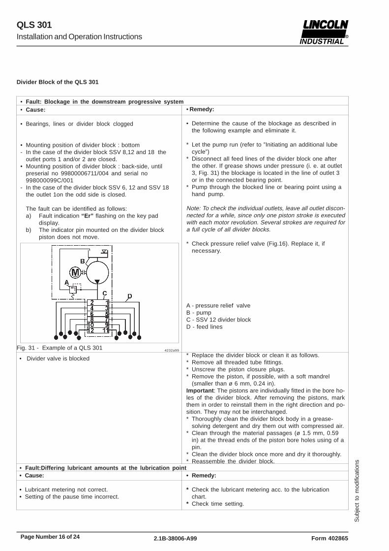
• Fault: Blockage in the downstream progressive system• Remedy:
• Determine the cause of the blockage as described inthe following example and eliminate it.
* Let the pump run (refer to ”Initiating an additional lubecycle”)
* Disconnect all feed lines of the divider block one afterthe other. If grease shows under pressure (i. e. at outlet3, Fig. 31) the blockage is located in the line of outlet 3or in the connected bearing point.
* Pump through the blocked line or bearing point using ahand pump.
Note: To check the individual outlets, leave all outlet discon-nected for a while, since only one piston stroke is executedwith each motor revolution. Several strokes are required fora full cycle of all divider blocks.
* Check pressure relief valve (Fig.16). Replace it, ifnecessary.
• Divider valve is blocked
• Fault:Differing lubricant amounts at the lubrication point• Cause:
• Lubricant metering not correct.• Setting of the pause time incorrect.
• Remedy:
* Check the lubricant metering acc. to the lubricationchart.
* Check time setting.
* Replace the divider block or clean it as follows.* Remove all threaded tube fittings.* Unscrew the piston closure plugs.* Remove the piston, if possible, with a soft mandrel
(smaller than ø 6 mm, 0.24 in).Important : The pistons are individually fitted in the bore ho-les of the divider block. After removing the pistons, markthem in order to reinstall them in the right direction and po-sition. They may not be interchanged.* Thoroughly clean the divider block body in a grease-
solving detergent and dry them out with compressed air.* Clean through the material passages (ø 1.5 mm, 0.59
in) at the thread ends of the piston bore holes using of apin.
* Clean the divider block once more and dry it thoroughly.* Reassemble the divider block.
A - pressure relief valveB - pumpC - SSV 12 divider blockD - feed lines
Fig. 31 - Example of a QLS 301
• Cause:
• Bearings, lines or divider block clogged
• Mounting position of divider block : bottom- In the case of the divider block SSV 8,12 and 18 the
outlet ports 1 and/or 2 are closed.• Mounting position of divider block : back-side, until
preserial no 99800006711/004 and serial no998000099C/001
- In the case of the divider block SSV 6, 12 and SSV 18the outlet 1on the odd side is closed.
The fault can be identified as follows:a) Fault indication “Er” flashing on the key pad
display.b) The indicator pin mounted on the divider block
piston does not move.
4232a99

Sub
ject
to
mod
ifica
tions
Page Number 17 of 242.1B-38006-A99
QLS 301
Form 402865
Installation and Operation Instructions
Technical Data
• The printed circuit boards for Direct Current DC :- are EMV regulation for on-road vehicles acc. EN 40839
parts 1, 3 and 4- the vehicle guide line 95/245/EC
Time settingFactory settingPause time...............................................................6 hours/cycleLubrication cycle time ............................... 20 min. to 100 hrs
........................................................... increment 1 minuteNumbers of cycles, general ................................................. 1with SSV 6, 8 divider block .......1, 2 or 3 cycles are possibleTimer memory ................................. indefinite over EEPROM
Operating temperature ..... -25° C to 70° C (-10° F to 160° F)Maximum operating pressurepump model without divider block .......205 bar (3,000 psig)Number of outlets .............................................. 6, 8, 12 or 18Output per outlet and cycle ........... approx.0.2 cm³ (0.012 in³)Reservoir capacity ............................................. 1.0 L (61 in³)Lubricant ............................................... up to NLGI 2 GreaseWeight (average) ......................................... 5.7 kg. (12.5 lbs)Protection .................................................... IP6K9K (NEMA 4)Reverse polarity protection:The operating voltage inlets are protected against reversepolarity
Electrical Data AC (Alternate Current)
Operating voltage ..................................... 120/60 Hz +/- 10 %Operating current .............................................................1.0 AOperating voltage ....................... 230 VAC;50/60 Hz+/- 10 %Operating current .............................................................0.5 A
Electrical Data DC (Direct Current)
Operating voltage ..................................... 12 V - 20 %/+ 30 %Operating current .............................................................2.0 AOperating voltage .................................. 24 V - 20 %/ + 30 %Operating current .............................................................1.0 AResidual ripple in relationto the operating voltage . ....................± 5% acc. to DIN 41755
Note: The pump motor is suitable for intermittent operationonly
Electric motor to housing....................................3 Nm (2.5 lb-ft)Pump element in housing............................25 Nm ( 19.0 lb-ft).
Lines
Plastic tube (dia. 6x1.5 mm; 1/4 in.)Min. bending radius................................................50 cm (2 in.)Bursting pressureat 20° C ( 70°F)............................ approx. 210 bar (3050 psi )Min. temperature...................................................-25° C (-10°F)
Closure plug (piston) in divider block ............ 18 Nm (13.5 lb-ft)Closure plug (outlets) in divider block ........... 15 Nm (11.0 lb-ft)
Outlet fitting in divider blockscrew-type ................................................. 17 Nm (12.5 lb-ft)push-in type .................................................12 Nm (9.0 lb-ft)
Compression nut onto outlet fitting, screw-typeplastic tube ..................................................10 Nm (7.5 lb-ft)steel tube ..................................................... 11 Nm (8.0 lb-ft)
Indicator pin in divider block .......................... 18 Nm (13.5 lb-ft)Mounting of the divider block ...........................10 Nm (8.0 lb-ft)
Tightening Torques
Relay for MalfunctionPotential-free outlet for malfunction/low level optionSwitching voltage.................................max. 230 VAC/125 VDCSwitching current (resistive)...................................................2 ASwitching capacity...................................................460 VA/80 W
Note: All datas are depending on operating voltage, ambi-ent temperature and max. operating pressure.
Pump
Divider block, accessories
QLS 301, general

Page Number 18 of 24
QLS 301
Sub
ject
to
mod
ifica
tions
2.1B-38006-A99 Form 402865
Installation and Operation Instructions
DimensionsQLS 301
Number of Outlets Dimensions A in mm (in.)8 75 (2.95)12 105 (4.13)18 150 (5.90)
4234a99
Fig.32- Dimensions of QLS 301
2012a95
Number of Outlets Dimensions A in mm (in.)6 60 (2.36)12 105 (4.13)18 150 (5.90)
4233a99
Fig.33- Dimensions of bottom mounted SSV Divider Blocks
Fig.34- Dimensions of back mounted SSV Divider Blocks

Sub
ject
to
mod
ifica
tions
Page Number 19 of 242.1B-38006-A99
QLS 301
Form 402865
Installation and Operation Instructions
Service Parts for the QLS 301QLS 301 with bottom mounted SSV Divider Block
4193a99
Fig 35 - QLS 301 with bottom mounted SSV Divider Block

Page Number 20 of 24
QLS 301
Sub
ject
to
mod
ifica
tions
2.1B-38006-A99 Form 402865
Installation and Operation Instructions
Parts list
Pos. Designation Kit Part Qty Part no.
1 Reservoir x 1 550-36979-22 Spring for follower
plate x 1 218-14172-63 Follower plate x 1 550-36979-34 Intermediate bottomx 1 450-24749-15 Eccentric gear x 1 550-36979-46 Shaft x 1 550-36979-17 Pressure relief
valve x 1 235-14343-18 Pump element,
assy dia. 6 mm x 1 650-28856-19 Sealing parts
for pump element x 1 550-36979-510 Housing with
low level control x 1 550-36981-3Housing withoutlow level control x 1 550-36981-4
11 Housing coverwith low level controlfor direct currentVDC, plug 1A1.0 x 1 550-36984-1for direct currentVDC, plug 1+2A1.0 x 1 550-36984-2
Housing cover withlow level controlfor alternate currentVAC, plug 1A1.0 x 1 550-36984-3for alternate currentVAC, plug 1+2 A1.0 x 1 550-36984-4
11.1 Socket 2 with 10 m cable,for remote control x 1 664-36078-8
11.2 Socket, blackGMD-3011 x 2 236-13277-9
11.3 Flat packing x 2 236-13294-311.4 Appliance plug 2,
for remote control, VDC x 1 664-36968-6Appliance plug 2,for remote control, VAC x 1 664-36968-5
11.5 Appliance plug 1,for power supplyl, VDC x 1 664-36968-4Appliance plug 1,for power supply, VAC x 1 664-36968-3
11.6 Socket 1 with 10 m cable,for power supply x 1 664-36078-7
12 Proximity switch x 1 550-36980-113 Printed circuit board for 1 cycle
12/24 VDC x 1 550-36983-1120 VAC x 1 550-36983-3230 VAC x 1 550-36983-5
Printed circuit board for max. 3 cycles
12/24 VDC x 1 550-36983-2120 VAC x 1 550-36983-4230 VAC x 1 550-36983-6
14 Low level control x 1 550-36979-915 Motor, 12 VDC x 1 550-36982-1
Motor, 24 VDC x 1 550-36982-1Motor, 120 VAC x 1 550-36982-1Motor, 230 VAC x 1 550-36982-1
15.1 Motor connection VDC x 1 664-36968-215.2 Motor connection VAC x 1 664-36968-116 Hydraulic lube fitting,
ST AR 1/8 cyl. x 1 251-14040-117 Adapter M 22x1.5
(o) x 1/8 in.(i) x 1 304-19619-118 O-ring dia. 5 x1.5 mm x 1 219-12222-219 Banjo bold x 1 226-13777-220 Sealing ring, aluminium x 2 226-13780-121 Manifold x 1 550-36979-622 Connecting block x 1 550-36979-723 Hydraulic lube fitting,
ST AR 1/8 cyl. x 1 251-14040-124 SSV divider block
SSV 8 - K x 1 619-37586-1SSV 12 - K x 1 619-37587-1SSV 18 - K x 1 619-37588-1
25 Piston plug withsealing for control pin x 1 519-32123-1
Sealing kit for QLS 301 1 550-36978-8
Pos. Designation Kit Part Qty Part no.

Sub
ject
to
mod
ifica
tions
Page Number 21 of 242.1B-38006-A99
QLS 301
Form 402865
Installation and Operation Instructions
QLS 301 with back mounted SSV Divider Block
4194a99
Fig 36 - QLS 301 with back mounted SSV Divider Block

Page Number 22 of 24
QLS 301
Sub
ject
to
mod
ifica
tions
2.1B-38006-A99 Form 402865
Installation and Operation Instructions
Pos. Designation Kit Part Qty Part no.
1 Reservoir x 1 550-36979-22 Spring for follower
plate x 1 218-14172-63 Follower plate x 1 550-36979-34 Intermediate bottomx 1 450-24749-15 Eccentric gear x 1 550-36979-46 Shaft x 1 550-36979-17 Pressure relief
valve x 1 235-14343-18 Pump element,
assy dia. 6 mm x 1 650-28856-19 Sealing parts
for pump element x 1 550-36979-510 Housing with
low level control x 1 550-36981-1Housing withoutlow level control x 1 550-36981-2
11 Housing coverwith low level controlfor direct currentVDC, plug 1A1.0 x 1 550-36984-1for direct currentVDC, plug 1+2A1.0 x 1 550-36984-2
Housing cover withlow level controlfor alternate currentVAC, plug 1A1.0 x 1 550-36984-3for alternate currentVAC, plug 1+2 A1.0 x 1 550-36984-4
11.1 Socket 2 with 10 m cable,for remote control x 1 664-36078-8
11.2 Socket, blackGMD-3011 x 2 236-13277-9
11.3 Flat packing x 2 236-13294-311.4 Appliance plug 2,
for remote control, VDC x 1 664-36968-6Appliance plug 2,for remote control, VAC x 1 664-36968-5
11.5 Appliance plug 1,for power supplyl, VDC x 1 664-36968-4Appliance plug 1,for power supply, VAC x 1 664-36968-3
11.6 Socket 1 with 10 m cable,for power supply x 1 664-36078-7
12 Proximity switch x 1 550-36980-113 Printed circuit board for 1 cycle
12/24 VDC x 1 550-36983-1120 VAC x 1 550-36983-3230 VAC x 1 550-36983-5
Printed circuit board for max. 3 cycles12/24 VDC x 1 550-36983-2120 VAC x 1 550-36983-4230 VAC x 1 550-36983-6
14 Low level control x 1 550-36979-915 Motor, 12 VDC x 1 550-36982-1
Motor, 24 VDC x 1 550-36982-1Motor, 120 VAC x 1 550-36982-1Motor, 230 VAC x 1 550-36982-1
15.1 Motor connection VDC x 1 664-36968-215.2 Motor connection VAC x 1 664-36968-116 Hydraulic lube fitting,
ST AR 1/8 cyl. x 1 251-14040-117 Adapter M 22x1.5
(o) x 1/8 in.(i) x 1 304-19619-118 O-ring dia. 5 x1.5 mm x 2 219-12222-219 SSV divider block
SSV V 6 - K x 1 619-37589-1SSV V 12 - K x 1 619-37590-1SSV V 18 - K x 1 619-37591-1
20 Hydraulic lube fitting, ST AR 1/8 cyl. x 1 251-14040-1
21 Piston plug withsealing for control pin x 1 519-32123-1
Sealing kit for QLS 301 1 550-36978-8
Pos. Designation Kit Part Qty Part no.

Sub
ject
to
mod
ifica
tions
Page Number 23 of 242.1B-38006-A99
QLS 301
Form 402865
Installation and Operation Instructions
Tube fittings, Screw-type or Push-in type for SSV Outlets
Fig. 37 - Check valve, screw-type (option) for steel and plastictubes
1009a98
Fig. 38 - Different types of check valves, push-in type
• For high-pressure plastic hose (option, dia. 8.6x2.3mm)use check valves type A with reinforced collar and smoothflange.
A - Check valve with reinforced collarB - Check valve with knurled collar1a - Reinforced collar2a - Knurled collar
4156a98
Note: On construction machines or agricultural machines usehigh pressure plastic hoses. In such cases the check valvesof the divider blocks must have a reinforced collar and asmooth flange.
Important: Connect only high-pressure plastic hoses(ø 8.6x2.3 mm) with threaded sleeve and hose studs to thecheck valves with reinforced collars.
1 - Threaded sleeve2 - High-pressure plastic hose3 - Hose stud
Fitting the threaded sleeves and hose studs on the high- pres-sure plastic hose
• Screw the threaded sleeve (item 1 Fig. 40) counterclockwiseonto the high-pressure plastic hose (2) until the illustrateddimension of 11 mm is reached. Then screw the hose stud(3) into the threaded sleeve (1).
Important: Oil parts before screwing the parts 1 and 3 together.
1028a96
Optional for metric fittings (not provided in the accessory kits)
1 - Ferrule nut2 - Cutting ring3 - Valve body with sealing and ferrule
Fig. 40 -Preassembly of the threaded sleeves and hosestuds on the high - pressure plastic hose
1086a99
Fig. 39 - Check valves with reinforced collar and hose stud
Page Number 24 of 24
QLS 301
Sub
ject
to
mod
ifica
tions
2.1B-38006-A99 Form 402865
Installation and Operation Instructions
Declaration of conformity as defined by ma-chinery directive 89/392/EEC Annex II A
This is to declare that the design of the
QLS 301 lubrication system
in the version supplied by us, complier with the provisions ofthe directive 91/368/EEC
Applied harmonized standards in particular
EN 292 - 1 Safety of machinery part 1Basic terminology, methodology
EN 292 - 2 Safety of machinery part 2Technical principles and specifications
EN 809 Pumps and pump units for liquidsSafety requirements
EN 60204-1 Safety of machineryElectrical equipment of machinesPart 1: General requirements
Walldorf, 05.05.1999 , Dr. Ing. Z. Paluncic
Americas:One Lincoln WaySt. Louis, MO 63120-1578USAPhone +1.314.679.4200Fax +1.800.424.5359
Europe/Africa:Heinrich-Hertz-Str 2-8D-69183 WalldorfGermanyPhone +49.6227.33.0Fax +49.6227.33.259
Asia/Pacific:25 Int’l Business Park#01-65 German CentreSingapore 609916Phone +65.562.7960Fax +65.562.9967
© Copyright 1999Printed in GermanyWeb site:www.lincolnindustrial.com
Declaration of conformity according EMVdirective 89/336 EWG
We declarethat the model of the
Centralized Lubrication System QLS 301
in the version supplied by us, complies with the provisions ofthe above - mentioned directive
Applied harmonized standards in particular
EN 55011 Specifications, limits and methods ofmeasurement of radio disturbancecharacteristics of industrial, scientificand medial (ISM) radio-frequencyequipment
EN 50081-1 Electromagnetic combatibilityGeneric emission standardPart 1: residential, commercial and lightindustry
EN 50082-2 Electromagnetic combatibilityGeneric immunity standardPart 2: industrial environment
Walldorf, 05.05.1999 , Dr. Ing. Z. Paluncic


![Qls Online Presenter[1]](https://static.fdocuments.in/doc/165x107/547d3f40b4af9fce158b5304/qls-online-presenter1.jpg)