QL40A ANTI-TORSION - litectruss.it 1579 4736 3 2601 2601 3 1521 3043 3 1110 3331 3 884 3535 3 4 1173...
4
400 400 C A B Chords A: extruded tube Ø 50x4 mm EN AW 6082 T6 Diagonals B: extruded tube Ø 30x3 mm EN AW 6082 T6 Ends C: aluminium forks connector EN AW 6082 T6 Connection system KHLP: cylindrical pin + safety R-clip QL40A ANTI-TORSION Square section High Load aluminium truss with 40 cm long sides. It is diagonalized on all faces and is provided with an aluminium fork connection. This guarantees excellent rigidity and elevated resistance in both horizontal and vertical applications despite its reduced section. GATES AND ACCESSORIES code cm kg FL40035P 40X35X5 3.5 FL40049MS 40X49 - 5X5 4.1 MTC30F 48x48X1 5 MTC30G / MTC30D 48X48X1 4.2 KHLP Ø 2 0.15 LINEAR ELEMENTS code cm kg QL40100A 40X40X100 14.70 QL40130A 40X40X130 17.50 QL40200A 40X40X200 25.30 QL40300A 40X40X300 36.20
Transcript of QL40A ANTI-TORSION - litectruss.it 1579 4736 3 2601 2601 3 1521 3043 3 1110 3331 3 884 3535 3 4 1173...

400
400
C
A
B
Chords A: extruded tube Ø 50x4 mm EN AW 6082 T6
Diagonals B: extruded tube Ø 30x3 mm EN AW 6082 T6
Ends C: aluminium forks connector EN AW 6082 T6
Connection system KHLP: cylindrical pin + safety R-clip
QL40AANTI-TORSION Square section High Load aluminium truss with 40 cm long sides. It is diagonalized on all faces and is provided with an aluminium fork connection. This guarantees excellent rigidity and elevated resistance in both horizontal and vertical applications despite its reduced section.
GATES AND ACCESSORIES code cm kg
FL40035P 40X35X5 3.5FL40049MS 40X49 - 5X5 4.1MTC30F 48x48X1 5MTC30G / MTC30D 48X48X1 4.2KHLP Ø 2 0.15
LINEAR ELEMENTS code cm kg
QL40100A 40X40X100 14.70QL40130A 40X40X130 17.50QL40200A 40X40X200 25.30QL40300A 40X40X300 36.20

87
m q am.- kg/m q am.- kg defl.- mm F am. - kg defl.- mm
1 2 3 4 5 6 7
1844752422272190139105
1844150412671087948831736
039
18324971
15191120881723608520450
16
16325379
111
2775910833495128131820
H m N am. Kg
3 6 9 12 15
TRUSSESHIGH LOAD FORK TRUSSES
QL40A
point full central load load deflection kg/m kg mm
point full central load load deflection kg kg mm
point full central load load deflection kg kg mm
point full central load load deflection kg kg mm
point full central load load deflection kg kg mm
Load table has been prepared in accordance with UNI ENV 1999-1-1 (Eurocode 9). When calculating the allowable loads it is assumed that the load is suspended from the bottom chord and the truss is supported from the top chord at each end.
The values shown in the table are the allowable static loads that can be applied to the truss. This is the live load or the payload.The self weight of the truss has been taken into account when calculating the values in the table.
It should be noted that this are idealised loading conditions and the User shall re-analyze the truss for the loading conditions which prevail for the application being considered.
QL40A ANTI-TORSION
3 1579 4736 3 2601 2601 3 1521 3043 3 1110 3331 3 884 3535 3 4 1173 4693 8 2264 2264 6 1360 2720 6 1010 3031 6 814 3256 7 5 891 4456 15 2004 2004 11 1229 2458 11 926 2778 12 754 3016 12 6 692 4151 24 1795 1795 17 1119 2239 18 854 2562 19 702 2809 20 7 549 3842 35 1624 1624 24 1027 2055 26 793 2378 28 657 2628 29 8 445 3561 49 1480 1480 33 947 1895 36 738 2213 39 616 2465 41 9 362 3260 64 1358 1358 43 879 1757 48 690 2069 52 580 2320 55 10 301 3007 82 1253 1253 55 818 1636 61 647 1940 67 546 2184 72 11 253 2779 101 1160 1160 69 764 1527 77 608 1824 85 504 2015 89 12 212 2547 121 1079 1079 84 715 1430 95 573 1720 105 467 1867 108 13 179 2327 143 1006 1006 101 671 1342 114 541 1622 127 434 1736 130 14 153 2136 165 941 941 120 631 1262 136 512 1536 152 405 1621 153 15 131 1969 190 881 881 141 595 1190 159 484 1453 178 379 1514 178 16 114 1822 216 827 827 163 561 1121 185 455 1366 206 355 1419 205 17 99 1690 244 779 779 187 530 1061 212 423 1268 233 333 1333 234 18 87 1572 273 733 733 213 501 1003 242 393 1179 261 313 1253 265 19 77 1464 304 691 691 240 475 950 274 366 1098 291 295 1179 298 20 68 1366 337 652 652 270 450 899 308 342 1025 323 278 1111 333
CENTRE POINT LOAD THIRD POINT LOAD QUARTER POINT LOAD FIFTH POINT LOAD UNIF. DISTRIBUTED LOAD
SPANm
LOAD TABLE / FORK CONNECTION
CANTILEVER LOAD TABLE / FORK CONNECTION
UNIFORMLY DISTRIBUTED LOAD SPAN CENTRE POINT LOAD
AXIAL LOAD TABLE
AXIAL LOAD N
HIGH LOAD FORK TRUSSES
QL40A / CONNECTIONS
QL40A / ACCESSORIES
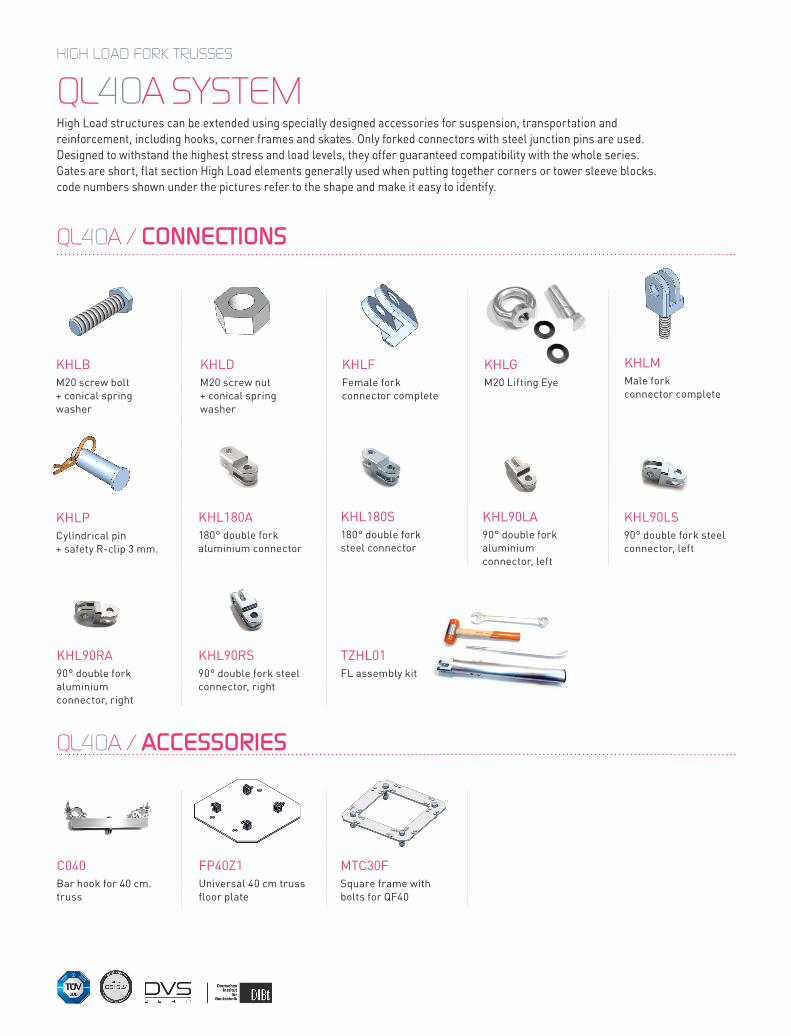
QL40A SYSTEM High Load structures can be extended using specially designed accessories for suspension, transportation and reinforcement, including hooks, corner frames and skates. Only forked connectors with steel junction pins are used. Designed to withstand the highest stress and load levels, they offer guaranteed compatibility with the whole series. Gates are short, flat section High Load elements generally used when putting together corners or tower sleeve blocks. code numbers shown under the pictures refer to the shape and make it easy to identify.
KHLDM20 screw nut + conical spring washer
KHLFFemale fork connector complete
C040Bar hook for 40 cm. truss
KHLGM20 Lifting Eye
FP40Z1Universal 40 cm truss floor plate
KHLMMale fork connector complete
MTC30FSquare frame with bolts for QF40
KHLBM20 screw bolt + conical spring washer
KHLPCylindrical pin + safety R-clip 3 mm.
TZHL01FL assembly kit
KHL180A180° double fork aluminium connector
KHL90RS90° double fork steel connector, right
KHL180S180° double fork steel connector
KHL90LA90° double fork aluminium connector, left
KHL90LS90° double fork steel connector, left
KHL90RA90° double fork aluminium connector, right
89
HIGH LOAD FORK TRUSSES / SYSTEM
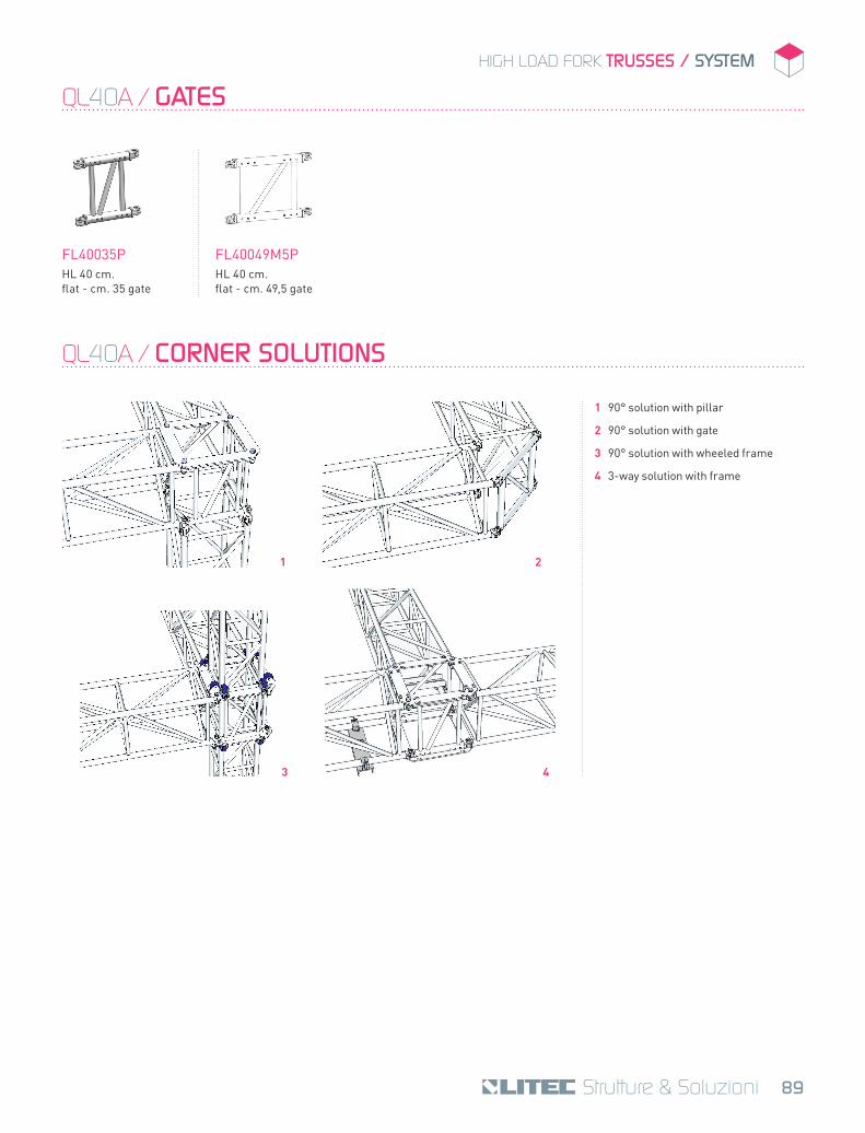
QL40A / GATES
FL40035PHL 40 cm. flat - cm. 35 gate
FL40049M5PHL 40 cm. flat - cm. 49,5 gate
QL40A / CORNER SOLUTIONS
1 2
3 4
1 90° solution with pillar
2 90° solution with gate
3 90° solution with wheeled frame
4 3-way solution with frame