
(QJLQHHU 5HFRQQDLVVDQFH - BITS98).pdf · ENGINEER RECONNAISSANCE ... Base Course and Subgrade ......
253
FM 5-170 (QJLQHHU 5HFRQQDLVVDQFH Headquarters, Department of the Army DISTRIBUTION RESTRICTION: Approved for public release; distribution is unlimited.
Transcript of (QJLQHHU 5HFRQQDLVVDQFH - BITS98).pdf · ENGINEER RECONNAISSANCE ... Base Course and Subgrade ......
FM 5-170
(QJLQHHU
5HFRQQDLVVDQFH
Headquarters,Department of the Army
DISTRIBUTION RESTRICTION: Approved for public release; distribution is unlimited.
C1, FM 5-170
Change 1 HeadquartersDepartment of the Army
Washington, DC, 1 3 July 1998
Enginee r Reconnaissance
1. Change FM 5-170, 5 May 1998, as follows:
Remove Old Pages Insert New Pages5-31 through 5-34 5-31 through 5-34References-1 and References-2 References-1 and References-2
2. A bar (I) marks new or changed material.
3. File this transmittal sheet in front of the publication.
DISTRIBUTION RESTRICTION: Approved for public release; distribution is unlimited.
By Order of the Secretary of the Army:
DENNIS J. REIMERGeneral, United States Army
Chief of Staff
Administrative Assistant to theSecretary of the Army
DISTRIBUTION:
Active Army, USAR, and ARNG: To be distributed in accordance with the initial distributionnumber 115747, requirements for FM 5-170.
*FM 5-170
Field Manual HeadquartersNo. 5-170 Department of the Army
Washington, DC, 5 May 1998
ENGINEER RECONNAISSANCE
Table of Contents
Page
Preface.............................................................................................................................................. vi
Chapter 1. Introduction............................................................................................................. 1-1Organization............................................................................................................................... 1-1Missions ...................................................................................................................................... 1-1Characteristics, Capabilities, and Limitations ........................................................................ 1-2
General Organizational Characteristics ............................................................................ 1-2Engineer Recon Team Capabilities .................................................................................... 1-2Engineer Recon Team Limitations ..................................................................................... 1-3Platform-Specific Capabilities ............................................................................................ 1-4
Command and Support Relationships ...................................................................................... 1-5Attached ............................................................................................................................... 1-5Operational Control (OPCON)............................................................................................ 1-6Direct Support (DS) and General Support (GS)................................................................. 1-6
Chapter 2. Intelligence Preparation of the Battlefield and Reconnaissance and Surveillance Planning .......................................................................................................... 2-1Intelligence Preparation of the Battlefield (IPB) ..................................................................... 2-1R&S Planning............................................................................................................................. 2-4
Chapter 3. Tactical Reconnaissance ...................................................................................... 3-1Purpose and Fundamentals....................................................................................................... 3-1Recon Techniques....................................................................................................................... 3-3
Mounted Recon .................................................................................................................... 3-4Dismounted Recon............................................................................................................... 3-5Recon by Fire ....................................................................................................................... 3-5
Indirect Fire .................................................................................................................. 3-6Direct Fire ..................................................................................................................... 3-6
Aerial Recon ......................................................................................................................... 3-6Stealth Versus Aggressive Recon ....................................................................................... 3-7
DISTRIBUTION RESTRICTION: Approved for public release; distribution is unlimited.
____________________________*This manual supersedes FM 5-30, 22 September 1967, and FM 5-36, 10 May 1985.
i
Page
Route Recon ............................................................................................................................... 3-7Critical Tasks ...................................................................................................................... 3-8Techniques........................................................................................................................... 3-8Example of a Route Recon .................................................................................................. 3-9
Zone Recon ............................................................................................................................... 3-21Critical Tasks .................................................................................................................... 3-21Techniques......................................................................................................................... 3-21Example of a Zone Recon .................................................................................................. 3-22
Area Recon ............................................................................................................................... 3-32Critical Tasks .................................................................................................................... 3-32Techniques......................................................................................................................... 3-32Example of an Area Recon................................................................................................ 3-33
Chapter 4. Engineer Recon Team and Obstacle Reconnaissance.................................... 4-1Personnel and Equipment......................................................................................................... 4-1
Training ............................................................................................................................... 4-1Equipment ........................................................................................................................... 4-2
Vehicles ......................................................................................................................... 4-2Communications Equipment ....................................................................................... 4-2Weapon Systems........................................................................................................... 4-2Additional Equipment .................................................................................................. 4-2
Engineer Recon Team ............................................................................................................... 4-2Dismounted Element .......................................................................................................... 4-3Mounted Element................................................................................................................ 4-3Obstacle and Restriction Recon.......................................................................................... 4-3
Detection ....................................................................................................................... 4-4Area Security and Recon .............................................................................................. 4-4Obstacle Recon.............................................................................................................. 4-5COA Selection ............................................................................................................... 4-5COA Recommendation/Execution................................................................................ 4-7Examples of Obstacles/Restrictions............................................................................. 4-7
Employment Concepts............................................................................................................. 4-17Integrated as Part of the Brigade Intelligence-Collection Effort ................................... 4-17Assigned Brigade NAIs in a TF’s AO............................................................................... 4-18Working Under a TF’s Control ......................................................................................... 4-18
Support Considerations........................................................................................................... 4-19Responsibilities........................................................................................................................ 4-22
Chapter 5. Route Classification ............................................................................................... 5-1Route-Classification Overlay .................................................................................................... 5-1
Route-Classification Formula............................................................................................. 5-2Route Width .................................................................................................................. 5-3Route Type .................................................................................................................... 5-4MLC............................................................................................................................... 5-4Overhead Clearance ..................................................................................................... 5-5Route Obstructions ....................................................................................................... 5-5Snow Blockage and Flooding ....................................................................................... 5-5
Examples of the Route-Classification Formula ................................................................. 5-5Curve Calculations .................................................................................................................... 5-6
Measuring Methods ............................................................................................................ 5-6Tape-Measure Method.................................................................................................. 5-6
ii
Page
Triangulation Method................................................................................................... 5-6Formula Method............................................................................................................ 5-8
Curve Symbol....................................................................................................................... 5-9Series of Sharp Curves ........................................................................................................ 5-9
Slope Estimation ........................................................................................................................ 5-9Percent of Slope ................................................................................................................... 5-9
Clinometer Method ....................................................................................................... 5-9Map Method................................................................................................................. 5-10Pace Method ................................................................................................................ 5-10Angle-of-Slope Method ................................................................................................ 5-12
Slope Symbol...................................................................................................................... 5-13Description of Slope Symbols ............................................................................................ 5-14
Constrictions ............................................................................................................................ 5-14Underpasses ............................................................................................................................. 5-15Tunnels ..................................................................................................................................... 5-16
Tunnel Symbol ................................................................................................................... 5-17Overhead Clearance .......................................................................................................... 5-18Tunnel Reconnaissance Report......................................................................................... 5-20
Stream Recon ........................................................................................................................... 5-24Measurements ................................................................................................................... 5-24Preexisting Data ................................................................................................................ 5-25Stream Width..................................................................................................................... 5-25
Compass Method ......................................................................................................... 5-25Aiming Circle, Azimuth Indicator, or Alidade........................................................... 5-25GPS .............................................................................................................................. 5-25Direct Measurement ................................................................................................... 5-25
Current Velocities.............................................................................................................. 5-26Stream Approaches............................................................................................................ 5-26
Fords ......................................................................................................................................... 5-27Underwater Recon ................................................................................................................... 5-29Ferry Recon .............................................................................................................................. 5-32
Civil Ferries and Ferry Sites ............................................................................................ 5-32Ferry Information.............................................................................................................. 5-35
Military Ferry and Rafting...................................................................................................... 5-36Road Recon Procedure ............................................................................................................. 5-39
Base Course and Subgrade ............................................................................................... 5-39Road-Capacity Computations ........................................................................................... 5-43Road-Classification Formula............................................................................................. 5-43Examples of the Road-Classification Formula................................................................. 5-46
Bridge-Classification Recon..................................................................................................... 5-46Required Bridge Information for Classification Procedures ........................................... 5-46Required Information ........................................................................................................ 5-49Bridge Condition................................................................................................................ 5-51Width and Height Restrictions ......................................................................................... 5-51Bridge Traffic-Control Procedure ..................................................................................... 5-51Full North Atlantic Treaty Organization (NATO) Bridge Symbol ................................. 5-52The Bridge Reconnaissance Report .................................................................................. 5-54Other Information ............................................................................................................. 5-58Bridge Sketches ................................................................................................................. 5-59
Bypasses ................................................................................................................................... 5-60
iii
Page
Chapter 6. Combat Support ...................................................................................................... 6-1Indirect-Fire Support ................................................................................................................ 6-1
Mortar Support ................................................................................................................... 6-1Capabilities ................................................................................................................... 6-2Limitations.................................................................................................................... 6-2Available Munitions ..................................................................................................... 6-2
Field Artillery...................................................................................................................... 6-2Capabilities ................................................................................................................... 6-3Limitations.................................................................................................................... 6-3Available Munitions ..................................................................................................... 6-3
Fire-Support Team.............................................................................................................. 6-4Fire-Request Channels ....................................................................................................... 6-4
Engineer Recon Team Working Under Brigade Control ............................................ 6-4Engineer Recon Team Working in a TF’s Area or Under TF Control ....................... 6-6Engineer Recon Team Working with a Cavalry Squadron or
Under Troop Control .............................................................................................. 6-7Air Defense............................................................................................................................... 6-10
Passive Air Defense .......................................................................................................... 6-10Attack Avoidance........................................................................................................ 6-10Damage-Limiting Measures....................................................................................... 6-10
Active Air Defense............................................................................................................. 6-10Air Support .............................................................................................................................. 6-11Ground Surveillance Radar .................................................................................................... 6-12
Capabilities and Limitations............................................................................................ 6-12Employment ...................................................................................................................... 6-13
Chemical .................................................................................................................................. 6-13Capabilities and Limitations............................................................................................ 6-13Employment ...................................................................................................................... 6-14
Chapter 7. Combat Service Support ....................................................................................... 7-1Organization .............................................................................................................................. 7-1Supply Operations ..................................................................................................................... 7-2
Basic Load ........................................................................................................................... 7-2Classes of Supply ................................................................................................................ 7-2
Class I............................................................................................................................ 7-2Class II .......................................................................................................................... 7-3Class III and Class V.................................................................................................... 7-3Class IV ......................................................................................................................... 7-3Class VI ......................................................................................................................... 7-3Class VII........................................................................................................................ 7-3Class VIII ...................................................................................................................... 7-4Class IX ......................................................................................................................... 7-4
Techniques of Resupply ...................................................................................................... 7-4Maintenance Operations ........................................................................................................... 7-4
Responsibilities ................................................................................................................... 7-6Team Leader ................................................................................................................. 7-6Assistant Team Leader ................................................................................................ 7-7Unit Maintenance (Operator Level) ............................................................................ 7-8
Evacuation........................................................................................................................... 7-8Destruction .......................................................................................................................... 7-9
Medical Treatment and Evacuation ......................................................................................... 7-9
iv
Page
Wounded Soldiers ................................................................................................................ 7-9Soldiers Killed in Action.................................................................................................... 7-10
Prisoners................................................................................................................................... 7-10Prisoners of War ................................................................................................................ 7-10Captured Enemy Documents and Equipment ................................................................. 7-14Civilians ............................................................................................................................. 7-14
Appendix A. Metric Conversion Chart................................................................................... A-1
Appendix B. Bridge Classification.......................................................................................... B-1Bridge Signs .............................................................................................................................. B-1Width and Height Restrictions................................................................................................. B-2Classification Procedures ......................................................................................................... B-2
Appendix C Sample Reconnaissance OPORD...................................................................... C-1
Appendix D. Engineer Recon ................................................................................................... D-1
Appendix E. Signs ....................................................................................................................... E-1Military Route Signs ................................................................................................................. E-1
Hazard Signs....................................................................................................................... E-2Regulatory Signs................................................................................................................. E-3
Light Line ..................................................................................................................... E-3Bridge/Raft Signs ......................................................................................................... E-3Rectangular Bridge Signs ............................................................................................ E-4
Guide Signs ......................................................................................................................... E-7Directional Disks.......................................................................................................... E-7Headquarters and Logistical Signs ............................................................................. E-7Casualty Evacuation Route Signs ............................................................................... E-8Unit Direction Arrow ................................................................................................... E-9Military Detour Signs .................................................................................................. E-9
Road Markers in Areas of Heavy Snow ................................................................................... E-9Vehicle Signs ............................................................................................................................. E-9Sign Lighting........................................................................................................................... E-11
Appendix F. Military Load Classifications ........................................................................... F-1Requirement for Classification Numbers ................................................................................ F-1Procedures for Vehicle Classification....................................................................................... F-1
Temporary Procedure for Vehicle Classification .............................................................. F-1Expedient Procedure for Wheeled-Vehicle Classification ................................................ F-1Expedient Procedure for Tracked-Vehicle Classification ................................................. F-2
Appendix G. Symbols ................................................................................................................. G-1
Glossary............................................................................................................................ Glossary-1
References ................................................................................................................... References-1
Index ....................................................................................................................................... Index-1
v

Preface
Field Manual (FM) 5-170 describes how engineer recon teams support and augment a maneuverbattalion or brigade’s recon effort. It is designed as an engineer extension of FMs 17-95 and 17-98.This manual serves as a guide for both brigade and task force (TF) engineers, as well as forsubordinate leaders (especially recon team leaders) in planning, integrating, and conductingrecon operations. It also serves as a guide for the brigade and TF staffs and subordinatemaneuver commanders on the organization, capabilities, and employment of engineer reconteams.
This manual sets forth the principles of conducting engineer recon activities supporting amaneuver brigade or TF. It addresses engineer tactics, techniques, and procedures (TTP) thathighlight critical principles. However, the TTP are intended to be descriptive rather thanprescriptive; they are not a replacement for the TTP and standing operating procedures (SOPs)that are unique to the supported unit.
FM 5-170 is fully compatible with Army doctrine as contained in FM 100-5 and is consistent withother combined-arms doctrine. This is not a stand-alone manual. The user must have afundamental understanding of the concepts outlined in FMs 100-5, 100-7, 100-16, 71-1, 71-2, 71-3,17-95, 17-98, 5-71-100, 5-71-2, 5-71-3, 34-1, 34-2, 34-2-1, 34-130, 90-13, 90-13-1, 101-5, and101-5-1. This manual also implements Standardization Agreement (STANAG) 2269, EngineerResources, Edition 3; STANAG 2027, Marking of Military Vehicles, Edition 3; STANAG 2253,Roads and Road Structures, Edition 4; STANAG 2174, Military Routes and Route/Road Networks,Edition 4; STANAG 2154, Regulations for Military Motor Vehicle Movement by Road, Edition 6;and STANAG 2010, Military Load Classification Markings, Edition 5.
Appendix A contains an English to metric measurement conversion chart.
The proponent of this publication is Headquarters, United States (US) Army Engineer School(USAES). Send comments and recommendations on Department of the Army (DA) Form 2028directly to Commander, USAES, ATTN: ATSE-TD-D, Fort Leonard Wood, Missouri, 65473-6650.
Unless this publication states otherwise, masculine nouns and pronouns do not refer exclusivelyto men.
vi
Chapter 1
Introduction
Combat power is generated by combining the elements of maneuver,firepower, force protection, and leadership within a sound plan and thenaggressively, violently, and flexibly executing the plan to defeat an enemy.The key to using combat power effectively is gathering information aboutthe enemy and the area of operations (AO) through recon. A recon providescurrent battlefield information that helps a commander plan and conducttactical operations. A recon greatly enhances maneuver, firepower, andforce protection when properly executed.
ORGANIZATION
Engineer recon elements may consist of an engineer platoon, squad, team, orother element. During military operations, the engineer may be called on toassist the maneuver force during recon missions. These missions are normallyexecuted by engineer recon teams, which are organized according to unitSOPs. (See Chapter 4 for a complete discussion of the engineer recon team.)Engineer recon teams may operate independently; however, they normallyaugment cavalry scout platoons; mechanized, wheeled, or dismounted scoutplatoons; or other maneuver units directly involved in recon operations. Themost prominent scout platoon in a force is the high-mobility, multipurposewheeled vehicle (HMMWV) scout platoon.
If an engineer recon team is to augment a maneuver scout element, the teamshould be task-organized with equipment that is compatible with thesupported maneuver recon force. The engineer team may use its own vehicleor ride in the vehicles of the scout, cavalry, or infantry unit it supports. It maymove mounted or dismounted, depending on its current equipment,organization, command and control (C2) structure, and enemy situation.
MISSIONS
An engineer recon team's primary mission is collecting tactical and technicalinformation for the supported or parent unit. The team must be able toperform this mission mounted or dismounted, during the day or at night, andin various terrain conditions.
A tactical recon is conducted in a high-threat environment and is a combined-arms effort to—
• Collect information about the enemy’s location and obstacles and theterrain within the AO.
• Conduct limited marking of obstacles, routes, and demolition work.
• Conduct limited reduction of obstacles in conjunction with maneuverunits.
Introduction 1-1
FM 5-170
A technical recon is conducted in a low-threat environment. It may or may notbe a combined-arms effort to collect engineer-specific technical data on a pointor area target or route (see Chapter 5).
CHARACTERISTICS, CAPABILITIES, AND LIMITATIONS
An engineer recon team normally conducts operations as part of a largercombined-arms force. This team has capabilities and limitations that must beconsidered when they are employed.
GENERAL ORGANIZATIONAL CHARACTERISTICS
Characteristics of a typical recon team include the following:
• The engineer recon team usually depends on both the parent andsupported unit for combat support (CS) and combat service support(CSS).
• The scout platoon may perform a recon of two routes simultaneously(for trafficability only) if the engineer recon team is performing arecon with a HMMWV scout platoon.
• The engineer element will assist in reconning a zone 3 to 5 kilometerswide when working with a scout platoon during a zone recon mission.Mission, enemy, terrain, troops, and time available (METT-T)conditions may increase or decrease the zone’s size.
• The engineer recon team must train and rehearse in detail with theunit it supports to ensure that all soldiers understand the recon TTP.
ENGINEER RECON TEAM CAPABILITIES
An engineer recon team has the following capabilities. It—
• Increases the supporting unit’s recon capability concerning complexmine and wire obstacle systems, enemy engineer activities, and detailsof mobility along a route.
• Provides detailed technical information on any encountered obstacle.
• Conducts an analysis of what assets will be needed to reduce anyencountered obstacle.
• Marks bypasses of obstacles based on guidance from the supportedcommander. This guidance includes whether to mark bypasses and inwhich direction the force should maneuver when bypassing anobstacle.
• Assists in gathering basic enemy information.
• Provides detailed technical information on routes (includingclassification) and specific information on any bridges, tunnels, fords,and ferries along the route.
• Assists in acquiring enemy engineer equipment on the battlefield.
• Assists in guiding the breach force to the obstacle to be reduced.
1-2 Introduction
FM 5-170
ENGINEER RECON TEAM LIMITATIONS
An engineer recon team has the following limitations:
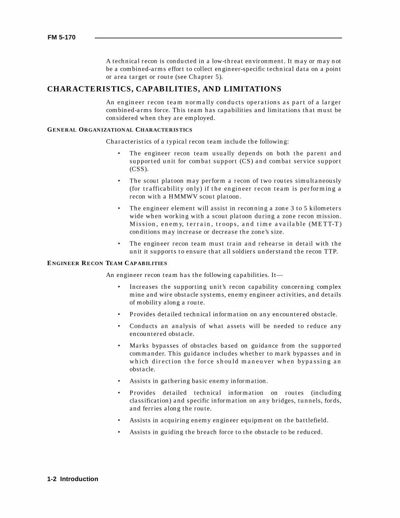
• Engineer battalions do not have personnel and equipment listed onthe table(s) of organization and equipment (TOE) and the modifiedtable(s) of organization and equipment (MTOE) dedicated to conduct arecon (see Figures 1-1 through 1-5, pages 1-3 through 1-7).
• The recon team has a limited ability to destroy or repel enemy reconunits and security forces.
• The distance the engineer recon team can operate away from the mainbody is restricted to the range of communications, the range ofsupporting indirect fires, and the ability to perform CSS operations.
• The recon team has a limited communications capability. Based on theradio configuration of the vehicle used during the recon and whetherthe engineer recon team is working under a maneuver element’s
Figure 1-1. Engineer battalion, engineer brigade, heavy division
Engineer Battalion, Engineer Brigade, Heavy Division*TOE 05335L000
Cbt Engr5-0-98-103
Support1-1-56-58
Equipment Recapitulation
30 - HMMWV 12 - Grizzly 1 - Welding trl28 - APC 6 - M548 1 - Shop equip org12 - Wolverine 8 - HEMTT cgo 1 - HYSTRU21 - ACE 4 - HEMTT POL 7 - M57712 - MICLIC 3 - MTV trk cgo 2 - MKT12 - 2½-t trl 2 - M88A1E1 (IRV) 6 - Volcano9 - LMTV trk cgo 3 - HMMWV/maint 6 - SEE6 - LMTV trl cgo 1 - HEMMT wrecker 2 - ¾-t trl4 - Water trl 2 - Water drum 18 - 1½-t trl
*The engineer battalion, enhanced brigade, has the same TOE.
HHC11-0-63-74
27-1-411-539
Introduction 1-3
FM 5-170
control, dedicated monitoring of engineer nets may be difficult.However, with the single-channel, ground-to-air radio system(SINCGARS), the recon team should be able to scan critical engineernets or, at the very least, easily switch to the engineer net to reportobstacle intelligence (OBSTINTEL).
• The engineer recon team has very limited obstacle creation andreduction ability. It normally carries only a light basic load ofdemolitions, according to the unit’s SOP. Obstacle reduction isnormally limited to manually reducing obstacles not covered by enemyfires and observation.
PLATFORM-SPECIFIC CAPABILITIES
An engineer recon team depends on its organic equipment and the equipmentof the unit it supports. Both the engineers and the supported unit mustdetermine the best combination of equipment based on METT-T.
The two engineer vehicles commonly used in recon operations are the M113A3armored personnel carrier (APC) and the M998 HMMWV. Both vehicles areeffective recon platforms when appropriately employed; however, securitymust come from the supported unit because the vehicles have limitedfirepower. The engineer must maximize his vehicle’s capabilities and minimize
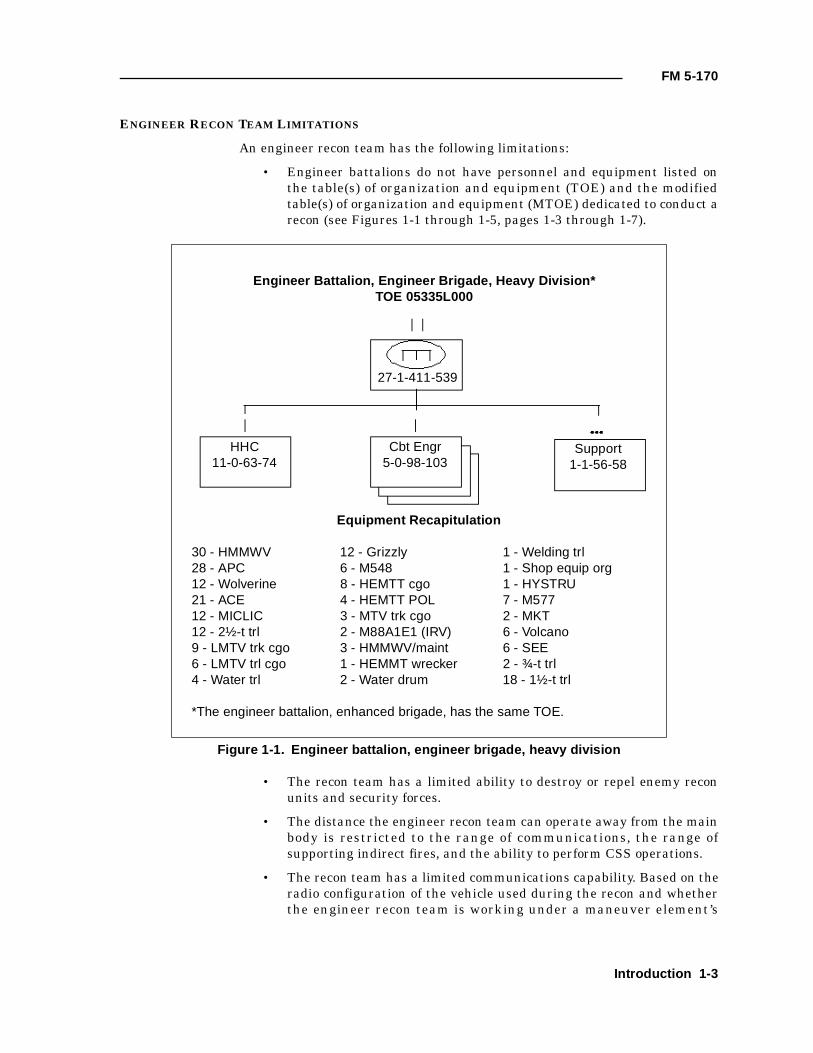
Figure 1-2. Engineer battalion, light infantry division
Engineer Battalion, Light Infantry DivisionTOE 05155L000
Equipment Recapitulation
3 - Volcano 3 - MTV trk cgo 1 - Water trl1 - HMMWV/maint 1 - MTV wrecker 6 - 40-t trl, LB3 - TUL 2 - MKT 6 - MET1 - LMTV trl 57 - HMMWV 3 - MTV trl cgo6 - Deuce 46 - ¾-t trl 18 - SEE1 - HYSTRU 2 - KCLFF 3 - MTV dump6 - Water drum 7 - LMTV trk cgo
33-1-376-410
HHC18-1-124-143
Cbt Engr5-0-84-89
1-4 Introduction
FM 5-170
its limitations. A third type of platform is that of a supported maneuver unitwhen it provides the engineer space on board its vehicle.
COMMAND AND SUPPORT RELATIONSHIPS
Engineers are task-organized a variety of ways, depending on the mission andcurrent requirements. This task organization drives an engineer recon team’scommand or support relationship.
ATTACHED
When attached, a recon team is temporarily placed in the unit it supports. Thecommander of the supported unit exercises the same degree of C2 as he doesover his organic units. In this relationship, the recon team receives all of itsmissions and support from the supported unit, not its organic engineer unit.Additionally, the supported-unit commander may task-organize the reconteam as he feels is appropriate.
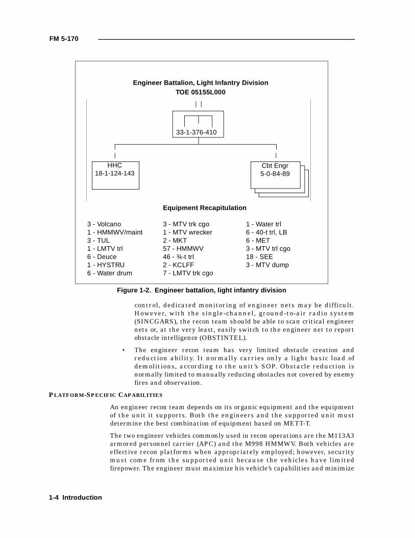
Figure 1-3. Engineer battalion, corps (mechanized)
Engineer Battalion, Corps (Mechanized)TOE 05435L300
HHC13-1-146-160
Cbt Engr5-0-100-105
28-1-446-475
Equipment Recapitulation
27 - APC 6 - M548 3 - HEMTT wrecker33 - HMMWV 6 - Volcano 1 - Welding trl18 - 1½-t trl 6 - SEE 3 - HMMWV/maint12 - MICLIC 6 - Bolster trl 13 - HEMTT cgo12 - 2½-t trl 2 - M577 4 - HEMTT POL12 - MTV dump trk 2 - MKT 1 - Shop equip org3 - 11-t flatbed trl 1 - Lube trl 1 - HYSTRU20 - LMTV trl cgo 3 - Water trl 5 - ¾-t trl21 - LMTV trk cgo 18 - ACE 1 - Forklift (atlas)12 - Wolverine 6 - TUL 3 - M88A1E112 - Grizzly 3 - Water drum
Introduction 1-5
FM 5-170
OPERATIONAL CONTROL (OPCON)
In an OPCON relationship, a recon team receives all of its tasking andmissions from the supported unit. The supported-unit commander retains thesame authority over the recon team as over his organic units and may task-organize the recon team as he feels is appropriate. Logistical support comesfrom the parent engineer unit unless the engineer battalion has coordinatedwith the supported unit for certain classes of supply.
DIRECT SUPPORT (DS) AND GENERAL SUPPORT (GS)
In a DS relationship, a recon team answers directly to the supported unit’srequests for support. Logistical support is provided by the parent engineerunit, and the recon team is commanded by its parent engineer unitcommander. In a GS relationship, a recon team receives missions and allsupport from its parent engineer unit.
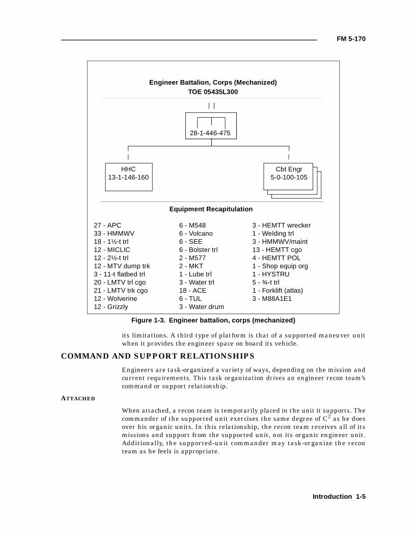
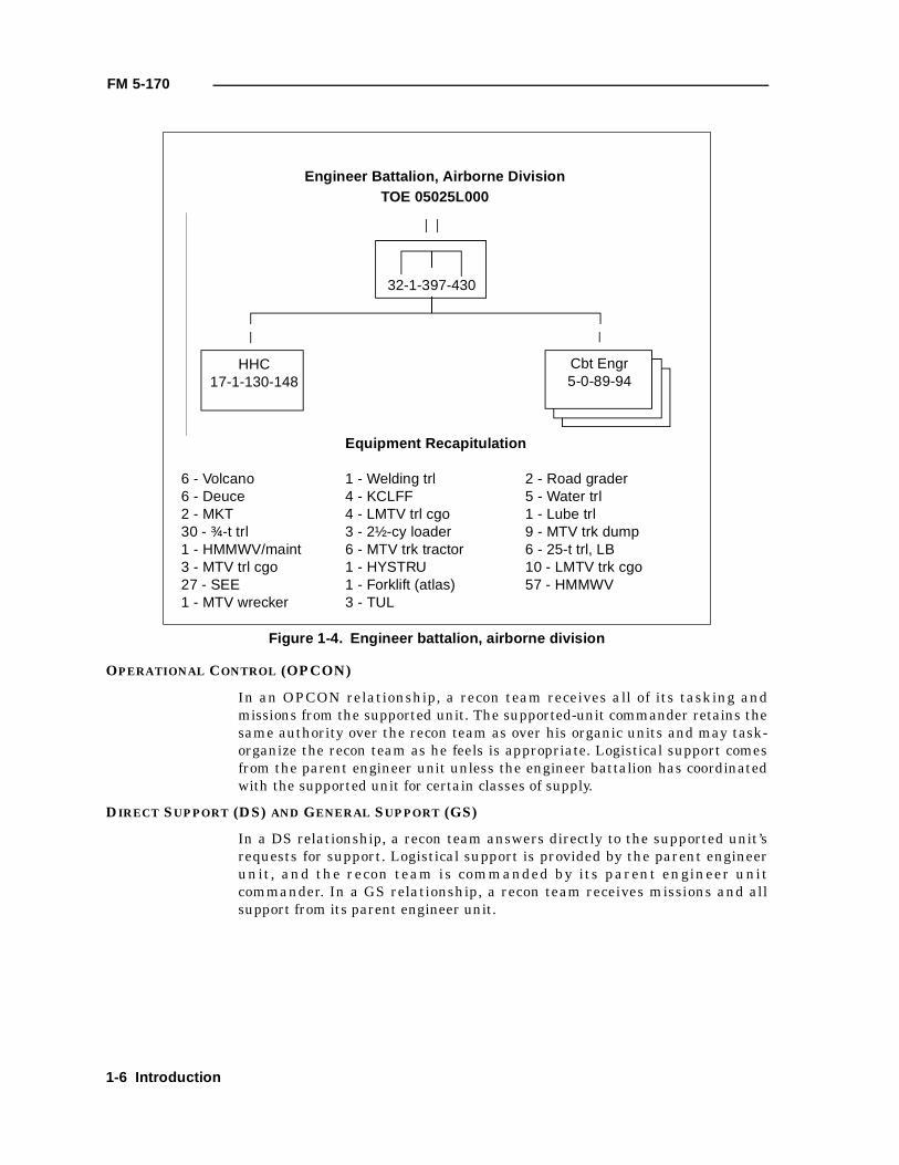
Figure 1-4. Engineer battalion, airborne division
Engineer Battalion, Airborne DivisionTOE 05025L000
HHC17-1-130-148
Cbt Engr5-0-89-94
Equipment Recapitulation
6 - Volcano 1 - Welding trl 2 - Road grader6 - Deuce 4 - KCLFF 5 - Water trl2 - MKT 4 - LMTV trl cgo 1 - Lube trl30 - ¾-t trl 3 - 2½-cy loader 9 - MTV trk dump1 - HMMWV/maint 6 - MTV trk tractor 6 - 25-t trl, LB3 - MTV trl cgo 1 - HYSTRU 10 - LMTV trk cgo27 - SEE 1 - Forklift (atlas) 57 - HMMWV1 - MTV wrecker 3 - TUL
32-1-397-430
1-6 Introduction
FM 5-170
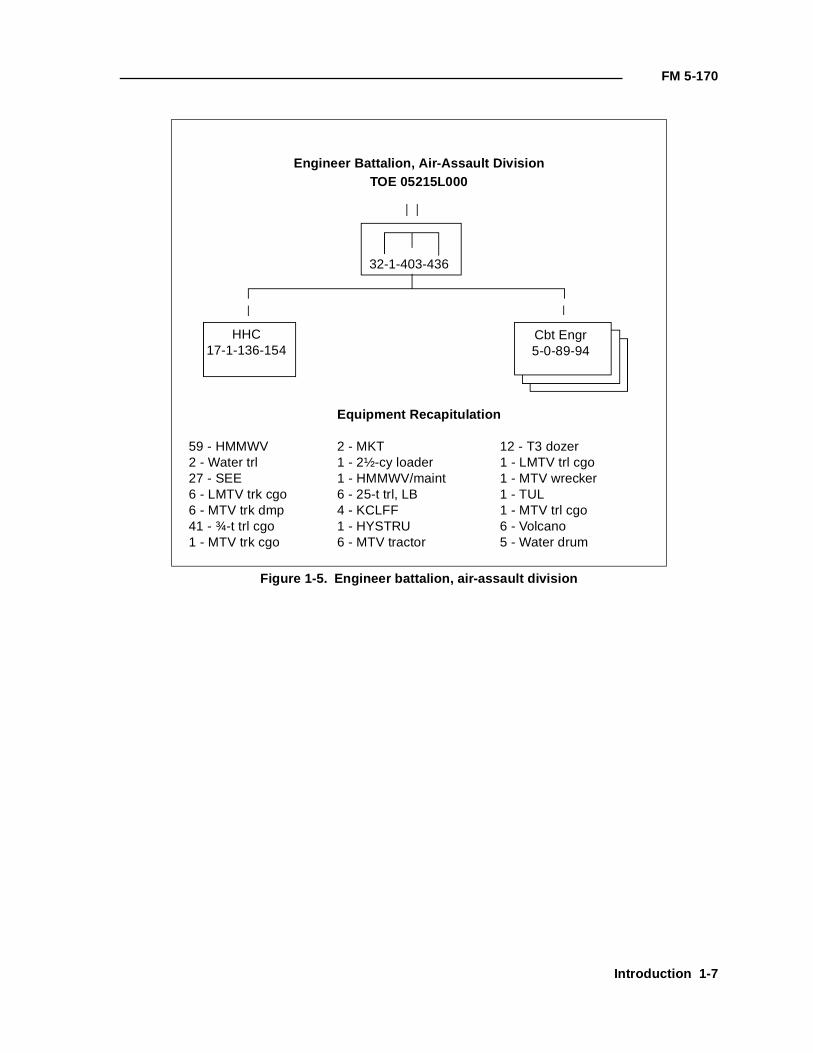
Figure 1-5. Engineer battalion, air-assault division
Engineer Battalion, Air-Assault DivisionTOE 05215L000
HHC17-1-136-154
Cbt Engr5-0-89-94
Equipment Recapitulation
59 - HMMWV 2 - MKT 12 - T3 dozer2 - Water trl 1 - 2½-cy loader 1 - LMTV trl cgo27 - SEE 1 - HMMWV/maint 1 - MTV wrecker6 - LMTV trk cgo 6 - 25-t trl, LB 1 - TUL6 - MTV trk dmp 4 - KCLFF 1 - MTV trl cgo41 - ¾-t trl cgo 1 - HYSTRU 6 - Volcano1 - MTV trk cgo 6 - MTV tractor 5 - Water drum
32-1-403-436
Introduction 1-7

FM 5-170
1-8 Introduction

Chapter 2
Intelligence Preparation of the Battlefield and Reconnaissance and Surveillance Planning
An engineer recon team performs several critical tasks in support of thesupported-unit commander’s concept of an operation. The recon team’ssuccess or failure often results in the force’s success or failure. As part ofthe commander’s “eyes” and “ears”, the recon team must maintaincommunication with the tactical operations center (TOC). Thiscommunication link is critical for the recon team to transmit intelligencegained to the TOC and for the TOC to pass to the recon team any currentinformation on the friendly and enemy situations.
The engineer recon team leader must clearly understand the commander’sintent and know what is expected of his team in each phase of theoperation. Also, he must be given the specific named areas of interest(NAIs) that his team is to observe and the exact information he is expectedto gather within each NAI. The engineer recon team must be focused onthe NAIs that concern obstacles, mobility, or enemy engineer assets.However, the team should be prepared to report on non-engineer-specificinformation as part of the combined-arms recon effort. The team must beprovided with all of the available information concerning the type ofobstacles they may encounter during the recon.
The engineer recon team must be a part of the supported unit ’sreconnaissance and surveil lance (R&S) plan. This ensures thatcommanders get the information they need to fight and win the battle. Amaneuver brigade and its subordinate battalions will produce R&S plans.The brigade plan will task the subordinate battalions, as well as brigadeassets, and these tasks will be incorporated into each subordinatebattalion’s plan.
NOTE: The R&S plan is developed very early in the planningprocess because it is critical to get recon assets into a mission asearly as possible.
INTELLIGENCE PREPARATION OF THE BATTLEFIELD (IPB)
IPB is a systematic approach to analyzing the an enemy, the weather, and theterrain in a specific geographic area. It integrates enemy doctrine with theweather and terrain as they relate to the mission and the specific battlefieldenvironment. This is done to determine and evaluate enemy capabilities,vulnerabilities, and probable courses of action (COAs). See FM 34-130 for acomplete discussion of IPB.
Intelligence Preparation of the Battlefield and Reconnaissance and Surveillance Planning 2-1
FM 5-170
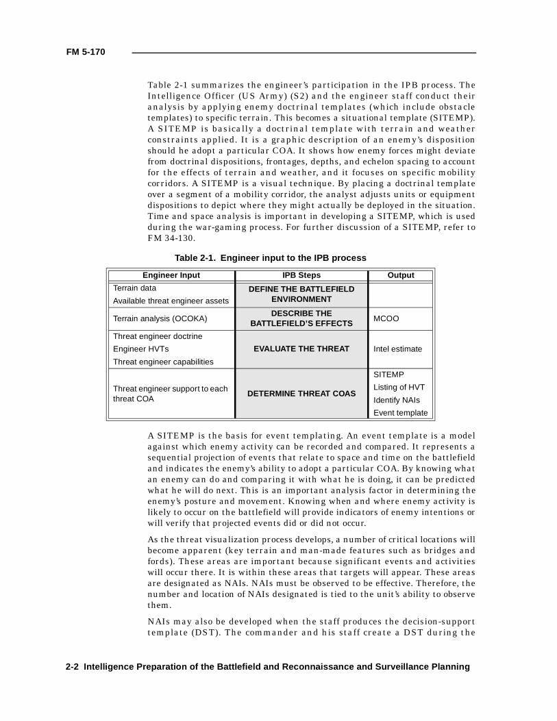
Table 2-1 summarizes the engineer’s participation in the IPB process. TheIntelligence Officer (US Army) (S2) and the engineer staff conduct theiranalysis by applying enemy doctrinal templates (which include obstacletemplates) to specific terrain. This becomes a situational template (SITEMP).A SITEMP is basically a doctrinal template with terrain and weatherconstraints applied. It is a graphic description of an enemy’s dispositionshould he adopt a particular COA. It shows how enemy forces might deviatefrom doctrinal dispositions, frontages, depths, and echelon spacing to accountfor the effects of terrain and weather, and it focuses on specific mobilitycorridors. A SITEMP is a visual technique. By placing a doctrinal templateover a segment of a mobility corridor, the analyst adjusts units or equipmentdispositions to depict where they might actually be deployed in the situation.Time and space analysis is important in developing a SITEMP, which is usedduring the war-gaming process. For further discussion of a SITEMP, refer toFM 34-130.
A SITEMP is the basis for event templating. An event template is a modelagainst which enemy activity can be recorded and compared. It represents asequential projection of events that relate to space and time on the battlefieldand indicates the enemy’s ability to adopt a particular COA. By knowing whatan enemy can do and comparing it with what he is doing, it can be predictedwhat he will do next. This is an important analysis factor in determining theenemy’s posture and movement. Knowing when and where enemy activity islikely to occur on the battlefield will provide indicators of enemy intentions orwill verify that projected events did or did not occur.
As the threat visualization process develops, a number of critical locations willbecome apparent (key terrain and man-made features such as bridges andfords). These areas are important because significant events and activitieswill occur there. It is within these areas that targets will appear. These areasare designated as NAIs. NAIs must be observed to be effective. Therefore, thenumber and location of NAIs designated is tied to the unit’s ability to observethem.
NAIs may also be developed when the staff produces the decision-supporttemplate (DST). The commander and his staff create a DST during the
Table 2-1. Engineer input to the IPB process
Engineer Input IPB Steps Output
Terrain data DEFINE THE BATTLEFIELD ENVIRONMENTAvailable threat engineer assets
Terrain analysis (OCOKA)DESCRIBE THE
BATTLEFIELD’S EFFECTSMCOO
Threat engineer doctrine
EVALUATE THE THREAT Intel estimateEngineer HVTs
Threat engineer capabilities
Threat engineer support to each threat COA
DETERMINE THREAT COAS
SITEMP
Listing of HVT
Identify NAIs
Event template
2-2 Intelligence Preparation of the Battlefield and Reconnaissance and Surveillance Planning
FM 5-170
decision-making process. A DST graphically represents the projectedsituation, identifying where a decision must be made to initiate a specificactivity or event.
NAIs developed during the IPB and decision-making process are prioritized,and recon assets are tasked to collect information to support the commander’sinformation requirements (IR). Engineer recon teams should be used for thoseNAIs requiring engineer expertise.
In the offense, a maneuver unit’s S2, with the engineer staff ’s assistance, willdetermine how and where an enemy will fight, how enemy direct-fire systemsand obstacles are arrayed, and what counterattack routes the enemy is likelyto take. The assistant brigade engineer (ABE) and the brigade S2 will alsoprovide input on enemy scatterable-mine (SCATMINE) capability and wherethe mines may be placed, based on how the enemy is predicted to fight. TheABE and the S2 provide any available information about existing obstacles onthe avenue of approach or mobility corridor. The TF S2 and the engineercompany executive officer (XO)/engineer platoon leader will incorporate thisinformation into their IPB.
In the offense, an engineer recon team's primary focus should be onOBSTINTEL as discussed in FM 90-13-1, Chapter 2. This includes but is notlimited to—
• Obstacle location.
• Obstacle orientation.
• The presence of wire.
• Gaps and bypasses.
• Minefield composition (buried or surface antitank [AT] andantipersonnel [AP] mines and antihandling devices [AHDs]) anddepth.
• Mine types.
• The location of enemy direct-fire weapons.
In the defense, a maneuver unit’s S2, with the engineer staff ’s assistance,conducts a terrain analysis to determine an enemy’s avenues of approach. TheABE and the brigade S2 work closely with the TF S2 and the engineercompany XO/engineer platoon leader in the TF’s TOC to provide input onenemy engineer assets and enemy engineer COAs and to template theenemy’s obstacle use. A recon team may be focused on—
• Obtaining information about planned routes to be used duringcounterattacks, repositioning, or retrograde operations.
• Augmenting the TF scouts to identify enemy engineer equipment andactivity.
• Observing locations where friendly forces will emplace scatterableminefields to provide information on its effectiveness and to call fireson enemy vehicles.
Intelligence Preparation of the Battlefield and Reconnaissance and Surveillance Planning 2-3
FM 5-170
• Observing NAIs where the enemy is expected to employ scatterableminefields.
R&S PLANNING
From an event template and a DST, the S2, in coordination with theOperations and Training Officer (US Army) (S3), prepares a detailed R&Splan that graphically depicts where and when the recon elements should lookfor enemy activity. The R&S plan must direct specific tasks and priorities toall R&S elements: company teams, scout platoons, engineer recon teams,combat observation and lazing teams (COLTs), ground-surveillance radar(GSR), and patrols. The supported battalion’s S2 translates the R&S plan intooperational terms and graphics. During recon operations, the S2 designatesNAIs for the engineer recon team. The S3 maintains overall OPCON of theR&S plan; however, the S2 plans and monitors the R&S plan. The engineerrecon team leader further refines the plan to include such things ascheckpoints as control measures to guide the team's movement to theseobjectives.
The supported unit’s S2 should brief the recon team leader on the dispositionof friendly forces and the unit’s scheme of maneuver. The S2 provides the teamleader with the current (and projected) R&S and operational graphics andterrain-index-reference-system (TIRS) points to support additional graphicsand fragmentary orders (FRAGOs). If the S3 does not brief the recon teamleader, the S2 must ensure that the commander's intent is accuratelyportrayed as he briefs the team leader. The S2 should plan to employ the reconteam throughout the mission’s entire course. He should provide guidance onwhen to report, what actions to take on enemy contact, and what CS and CSSassets are available. The engineer commander must ensure that specificsconcerning obstacles, terrain, and enemy engineer assets that may beencountered are also included in this briefing. The recon team leader shouldreceive the S2’s briefing before he departs the battalion area for his mission.Other options, although less desirable, include receiving this information overthe radio or from a messenger sent by the commander.
The engineer staff in either the brigade’s or the TF’s TOC should doeverything possible to assist the engineer recon team leader by coordinatingwith other battlefield operating system (BOS) elements. These types ofcoordination are discussed in the following paragraphs.
A fire-support element (FSE) stays abreast of what the team is doing whileconducting the mission. This ensures that it provides responsive fire supportto the recon team. The engineer staff should coordinate with the fire-supportofficer (FSO) to discuss the recon team’s mission and the unique requirementsthe team has for fire support. The engineer staff finds out what support isavailable, where supporting units are located, and what fire-supportrestrictions exist. The team leader then recommends preplanned targets andtarget priorities that the FSO will incorporate into a recon team’s fire-supportplan. The team leader should depart the FSE with an approved target listand/or preplanned fire overlay.
The engineer staff may also coordinate with the appropriate signal officer(engineer battalion, brigade, or TF) if the mission requires communications
2-4 Intelligence Preparation of the Battlefield and Reconnaissance and Surveillance Planning
FM 5-170
support. A retrans or relay support must be requested if the mission dictates.The engineer recon team should not perform relay duties as their primarymission; however, it is desirable for each vehicle used by the recon team tohave the capability to act as a retrans station.
The engineer staff also coordinates with any additional elements that may beproviding support to the recon effort (such as air-defense artillery [ADA],COLT, GSR, and aeroscouts). Ideally, any linkups should occur at the TOCduring daylight and in sufficient time to conduct a thorough briefing andrehearsal with elements that the recon team is attached to or elements thatare attached to the recon team. During a route recon, the engineer recon teammust know the number, type (track or wheeled), and load classification ofvehicles to be used on the reconned routes. This information will determineroute trafficability and help decide COAs during the recon.
The engineer staff coordinates with the appropriate unit Supply Officer (USArmy) (S4) (from the engineer battalion, brigade, or TF) to ensure that afeasible CSS plan is in place and that the recon team leader understandswhere all of his logistical support will come from. Detailed discussion of CSSand recon operations is in Chapter 7.
The engineer recon team leader should, as a minimum, have the followingmaterials on hand and available to his soldiers:
• Operational graphics.
• R&S graphics.
• The SITEMP, event template, and notes on the current enemysituation.
• The fire-support overlay.
• CSS plan (resupply, casualty evacuation, maintenance, and recovery)and CSS graphics.
• Communications plan.
• Compromise procedures.
• Disengagement criteria.
• Linkup plan.
• Contingency plan for NAI coverage.
Once in the vicinity of these recon objectives, the recon team confirms ordenies the templated information. The team—
• Looks for engineer-specific information about the obstacle, such as theobstacle’s composition and any bypasses around it.
• Considers limited obstacle reduction.
• Conducts an analysis of the terrain and soil composition to determinewhether mine-clearing blades or mine-clearing line charges(MICLICs) will be successful.
• Recommends the location for obstacle reduction.
Intelligence Preparation of the Battlefield and Reconnaissance and Surveillance Planning 2-5

FM 5-170
The information obtained by the engineer recon team must be relayed to theTOC quickly to allow the S2, the S3, and the engineer staff to analyze theinformation and ensure rapid dissemination to all units. The engineer staffshould ensure that it has a system in place to track all incoming OBSTINTELand the method of dissemination as well as a system to display confirmedOBSTINTEL graphically as opposed to templated obstacles.
2-6 Intelligence Preparation of the Battlefield and Reconnaissance and Surveillance Planning
Chapter 3
Tactical Reconnaissance
Engineers are active participants in recon operations that provide bothmaneuver and engineer commanders with information about the terrain,enemy engineer activity, obstacles, and weather effects within an AO. Atactical recon normally takes place in a high-threat environment. During arecon, engineers may assist maneuver units or scouts in reconning theterrain to determine its effect on maneuverability and the enemysituation. When the enemy is located, the engineers help determine hisstrengths and weaknesses with a focus on enemy engineer activities andobstacles. A recon team provides the information necessary to allowcombined-arms forces to maneuver against the enemy, attack him wherehe is most vulnerable, and apply overwhelming firepower to destroy him.An engineer recon team ensures that the combined-arms forces have thefreedom to maneuver and the knowledge of where they will encounterenemy obstacles. This chapter provides basic information on reconoperations. Its focus is on providing the engineers the information neededto allow them to integrate into a maneuver force’s recon effort. Althoughthis information is most pertinent to tactical recon missions, the methodsdiscussed should also be used by squads, platoons, and companies whenconducting technical recons.
PURPOSE AND FUNDAMENTALS
A tactical recon is conducted to gain information forward of friendly lines or toprovide current, accurate information about terrain, resources, obstacles, andthe enemy within a specified AO. This information provides the follow-onforces with an opportunity to maneuver to their objective rapidly. Engineerrecon teams are involved in three types of tactical recon: route, zone, and area.During a tactical recon, engineers may also be involved in various technicalrecons such as road, tunnel, and bridge recons.
There are six fundamentals common to all successful tactical recon operations.Every engineer leader should keep these fundamentals in mind whenplanning and executing recon missions.
• Using maximum recon force forward. During a recon, every scout,every engineer, and every pair of eyes make a difference. Engineerrecon teams must not be kept in the reserve. They must be employed,executing their portion of recon tasks as soon as possible.
• Orienting on the recon objective. A recon team's scheme of maneuveris focused toward a specific objective or a set of objectives. An engineerrecon team must know where to look for enemy obstacles and enemyengineer activity at the objective. The objective may be a terrain
Tactical Reconnaissance 3-1
FM 5-170
feature, a specific area, or an enemy force; it may be designated by anNAI, a checkpoint, or an objective symbol. A recon team mustmaintain its orientation toward the objective until the mission iscomplete. The overall objective for an engineer recon team’s mission islocated in the supported commander's priority intelligencerequirements (PIR), the R&S plan, and/or the commander's intentparagraph in the operations order (OPORD). It is critical that allrecon personnel understand the purpose of a recon mission.
• Reporting all information rapidly and accurately. Commanders basetheir decisions and plans on the battlefield information that scouts,engineers, and other recon assets find and report. Information losesvalue over time. Scouts and engineers must report all informationexactly as they see it and as fast as possible. They must never assume,distort, or exaggerate; inaccurate information is dangerous.Information that an enemy or an obstacle is not in a certain location isjust as important as where the enemy or obstacle is.
• Retaining freedom of maneuver. All recon elements must be able tomaneuver on the battlefield. If a recon element is fixed by the enemy,the element must regain its ability to maneuver or it can no longeraccomplish its mission. Recon teams must continually maintain anawareness of tactical developments. They must employ propermovement te ch niques and react to unexpected s ituat ion sappropriately. When contact is made, the recon team leader mustdevelop the situation and retain the initiative and the ability tocontinue the mission.
• Gaining and maintaining enemy contact. Recon elements employsound tactical movement, target-acquisition methods, and appropriateactions to make contact with an enemy, undetected, thereby retainingthe initiative and control of the situation. Recon elements use theterrain and weather to their advantage to avoid detection. Examplesinclude selecting covered and concealed routes, moving during rain,avoiding roads and danger areas, and selecting unlikely routes to theirobjectives. Once scouts find the enemy, they maintain contact using allavailable means (sensors, radar, sound, and visual) until thecommander orders them to do otherwise or as required by theirspecific instructions.
• Developing the situation rapidly. Whether recon elements detect anobstacle or the enemy, they must analyze the situation quickly. If theydetect the enemy, the recon elements determine the enemy's size,composition, and activity and locate the enemy’s flanks. Scouts andengineers find any obstacles protecting the enemy’s position. Theengineers (with scout assistance) find and mark a bypass, perform anunopposed obstacle reduction, or conduct a detailed obstacle recon. Itis imperative that any reduction/marking does not jeopardize therecon effort. It is also important that the engineers gain enough detailabout the obstacle for future breaching operations. This must be donequickly with minimum guidance from higher headquarters. During arecon, time is a precious resource; it cannot be wasted if missionsuccess is to be achieved.
3-2 Tactical Reconnaissance
FM 5-170
RECON TECHNIQUES
Recon techniques achieve a balance between the acceptable level of risk andthe security necessary to ensure mission accomplishment. This balance isoften a tradeoff between speed and security. The faster the recon, the morerisk a recon team accepts and the less detailed recon it conducts. A recon teammust use all available resources when conducting its mission. The primarytools for any engineer recon team are its senses—particularly, sight, hearing,touch, and smell. Recon equipment supplements and complements thesesenses. The following are some examples of how these senses are used duringrecon missions:
• Sight. An engineer recon team looks for—
— Evidence of digging activities, including fighting positions andtank ditches.
— Movement or activity of enemy engineer vehicles.
— Indications of buried mines.
— Emplaced demolition charges on bridges, tunnels, and so forth.
— Obstacle orientation, depth, composition, and width.
— Enemy vehicles and aircraft.
— Helicopter landing zones (LZs).
— Sudden or unusual movement.
— Smoke or dust.
— Engine exhaust fumes.
— Unusual movement of farm or wild animals.
— Activity of the local populace.
— Vehicle tracks.
— Signs or evidence of enemy occupation.
— Recently cut foliage or vegetation.
— Lights, fires, or reflections.
— Muzzle flashes.
• Hearing. An engineer recon team listens for—
— Vehicle sounds indicating construction of survivability positions.
— Exploding demolition charges.
— Running engines.
— Track sounds.
— Voices.
— Metallic sounds, especially sounds indicating wire emplacement.
— Gunfire sounds (by type of weapon).
Tactical Reconnaissance 3-3
FM 5-170
— Unusual calm or silence.
— Dismounted movement through brush or woods.
— Helicopter rotors.
• Touch. An engineer recon team feels for the presence of trip wires orAHDs.
• Smell. An engineer recon team smells for—
— Cooking food.
— Vehicle exhaust.
— Burning petroleum, oils, and lubricants (POL).
— Decaying food or garbage.
To reduce vulnerability on the battlefield, an engineer recon team rehearsesrecon techniques in detail. The knowledge and rehearsal of recon techniques,combined with an understanding of a mission's particular METT-Trequirements, allow the recon team leader to mix and choose the methods thatmaximize security and mission accomplishment.
This section discusses several recon methods that have proven to be effectivein most situations. They form the foundation for tactical recon. Use commonsense when analyzing a given situation and employing or modifying themethod based on METT-T.
MOUNTED RECON
Maneuver units frequently employ mounted recons. A fairly detailed reconcan be conducted while maintaining speed and momentum. Normally, amounted recon is used when—
• Time is limited.
• Long distances must be traveled.
• A very detailed recon is not required.
• Enemy locations are known.
• Enemy obstacles are known or not expected.
• Enemy contact is not likely.
In addition to speed, a mounted recon offers the advantages of a tacticalvehicle. These advantages depend on the vehicle employed, but they caninclude fi repower, armor protection , increased navigat ional aids,communication capabilities, and thermal optics. Recon teams must dismountand recon forward of their vehicles to provide security before moving throughdangerous areas such as open areas, hilltops, curves, wadis, or other blindspots on the battlefield. Disadvantages include the loss of stealth due to thevehicle’s visual, noise, and thermal signatures and the loss of some detailbecause of restricted vision and impairment of the senses of smell andhearing. These disadvantages increase the risk to personnel as they conduct arecon.
3-4 Tactical Reconnaissance
FM 5-170
DISMOUNTED RECON
A dismounted recon’s primary purpose is to obtain detailed information aboutterrain features, obstacles, or enemy forces. Engineer recon teams normallyconduct a dismounted recon. A dismounted recon is conducted when—
• A detailed recon is required.
• Stealth is required.
• Enemy contact is expected or visual contact has been achieved.
• Vehicle movement through an area is restricted by terrain.
• Time is not limited.
• Security is the primary concern.
Recon teams set up short- or long-duration observations posts (OPs).Dismounted personnel must provide security for each other when moving.They should work together in pairs when operating dismounted. When onlyone person dismounts, he should never move out of supporting distance of thevehicle.
As a minimum, a recon team should carry the following when dismounted:
• SOPs, to include templated information on anticipated obstacles.
• Personal weapons.
• Communications equipment.
• Signal operating instructions (SOI) extracts.
• Maps.
• A compass.
• Binoculars (night-vision devices [NVDs], if necessary).
• Seasonal uniform and load-bearing equipment.
• A global positioning system (GPS).
• Radios.
RECON BY FIRE
In a recon by fire, a recon element places direct/indirect fire on positionswhere there is a reasonable suspicion of enemy occupation. The goal is tocause an enemy to disclose his presence by moving or returning fire. Reconelements conduct a recon by fire when enemy contact is expected and time islimited or when they cannot maneuver to develop the situation. This methodeliminates any element of surprise the scouts may have had, and it is likely togive the enemy detailed knowledge of their location. However, it may reducethe chance of being ambushed within established kill zones. Recon by fire doesnot work in all cases. For example, disciplined troops in prepared positionswill not react to the scout's fires. Examples of situations in which a recon byfire may be employed include—
• The presence of a natural or man-made obstacle.
Tactical Reconnaissance 3-5
FM 5-170
• The existence of an obvious kill zone.
• A suspected enemy position that fits the SITEMP.
• Signs of recent activity (tracks, marks, or trash).
• Bunker complexes that may or may not be occupied.
When such evidence exists, the scouts should maneuver to observe fromdifferent directions. When the decision is finally made to conduct a recon byfire, weapons should be used in the following priority:
• Indirect fire.
• Dismounted machine gun.
• 25-millimeter (mm) chain gun, MK19, and mounted machine gun.
• Tube-launched, optically tracked, wire-guided missile (TOW).
Engineer recon teams do not normally provide a key weapon system during arecon by fire. They are better employed as an observation asset to the firingteam.
A recon by fire does not mean indiscriminately using direct and indirect firesat all wood lines and hilltops in the hopes of causing the enemy to react. Theenemy will recognize this for what it is; he will not react to it. This also wastesvaluable ammunition.
Indirect Fire
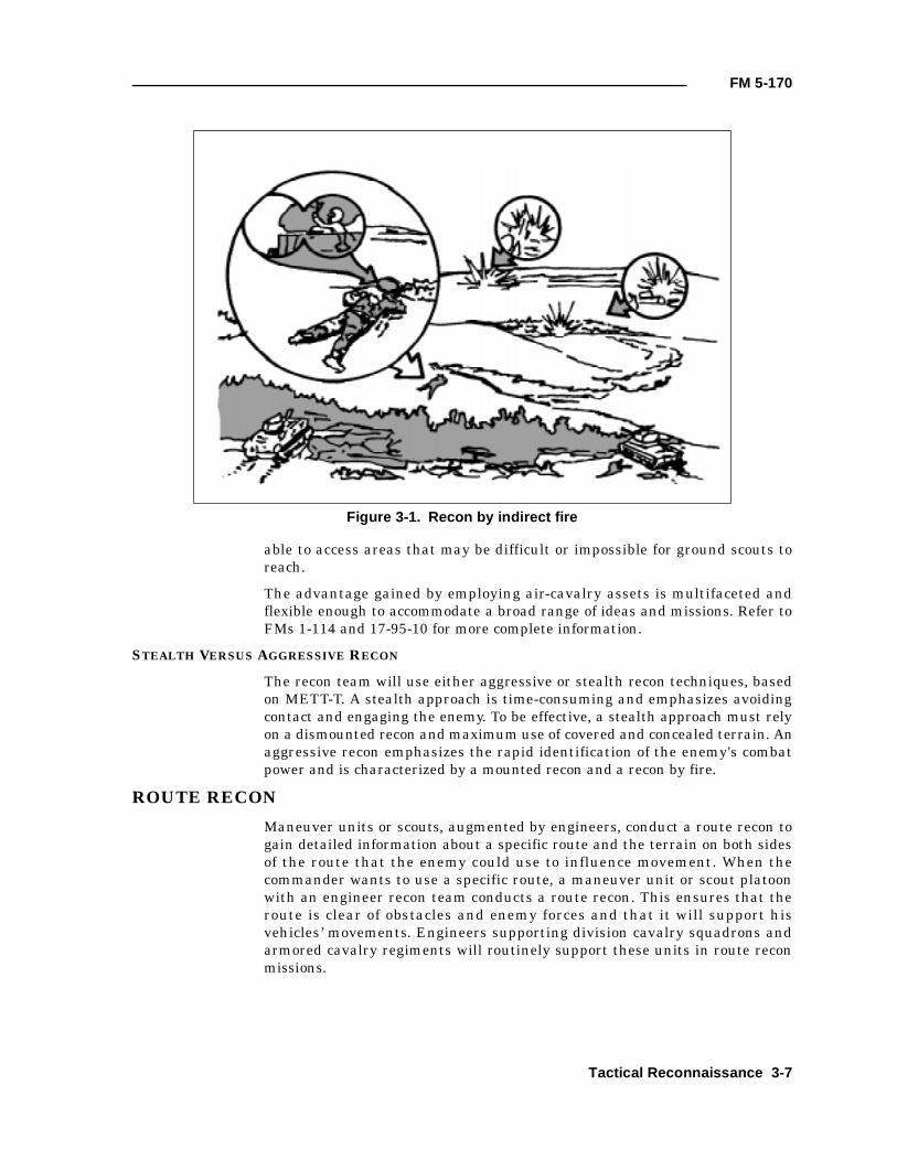
Scouts can employ recon by indirect fire (see Figure 3-1). This techniqueprovides them security because they do not disclose their exact position, andthey are all available to observe the effects of fire.
A recon by indirect fire has disadvantages as well. Indirect fire requires morecoordination and communication than direct fire. Indirect fire is subject toconsiderations beyond a recon team’s control such as the supporting unit'sClass V supply status, counterbattery threats, and command approval. Also,the effects of indirect fire may obscure a scout's vision.
Direct Fire
Scouts can use their organic weapons to place accurate direct fires onsuspected enemy positions. This technique is likely to provoke a rapid enemyresponse, but it reveals the scout's position. Scouts must work together whenemploying direct fire. A scout who fires is normally not in the best position toobserve because of obscuration and the necessity to move to a covered andconcealed position after firing. Another scout must observe for an enemyreaction. The recon leader should also plan on placing indirect fires onsuspected positions for use as suppression if the enemy responds in strength.
AERIAL RECON
An aerial recon is not normally available except in division cavalryorganizations or when supporting an armored cavalry regiment. Whenavailable, however, an aerial recon can be employed to complement andaugment a ground recon. An aerial recon, as conducted by air-cavalryelements, is the fastest form of recon. It is also terrain-independent and thus
3-6 Tactical Reconnaissance
FM 5-170
able to access areas that may be difficult or impossible for ground scouts toreach.
The advantage gained by employing air-cavalry assets is multifaceted andflexible enough to accommodate a broad range of ideas and missions. Refer toFMs 1-114 and 17-95-10 for more complete information.
STEALTH VERSUS AGGRESSIVE RECON
The recon team will use either aggressive or stealth recon techniques, basedon METT-T. A stealth approach is time-consuming and emphasizes avoidingcontact and engaging the enemy. To be effective, a stealth approach must relyon a dismounted recon and maximum use of covered and concealed terrain. Anaggressive recon emphasizes the rapid identification of the enemy's combatpower and is characterized by a mounted recon and a recon by fire.
ROUTE RECON
Maneuver units or scouts, augmented by engineers, conduct a route recon togain detailed information about a specific route and the terrain on both sidesof the route that the enemy could use to influence movement. When thecommander wants to use a specific route, a maneuver unit or scout platoonwith an engineer recon team conducts a route recon. This ensures that theroute is clear of obstacles and enemy forces and that it will support hisvehicles’ movements. Engineers supporting division cavalry squadrons andarmored cavalry regiments will routinely support these units in route reconmissions.
Figure 3-1. Recon by indirect fire
Tactical Reconnaissance 3-7
FM 5-170
CRITICAL TASKS
During a route recon, a recon element must accomplish a specified number oftasks unless directed to do otherwise. Based on time available and thecommander's intent, the recon element may be directed to conduct a routerecon to acquire specific information only. The recon leader must clearlyunderstand which of the following critical tasks must be accomplished:
• Determining the route’s trafficability. (For further information seeChapter 5.)
• Reconning to the limit of direct-fire range and terrain that dominatesthe route.
• Reconning all built-up areas along the route (includes identifyingbypass routes, construction supplies and equipment, ambush sites,evidence of booby traps, and suitable sites for C2/CSS facilities).
• Reconning all lateral routes to the limit of direct-fire range.
• Inspecting and classifying all bridges on the route.
• Locating fords or crossing sites near all bridges on the route (includesdetermining fordabilty and locating nearby bypasses that can supportcombat and CSS units, marking bridge classifications and bypassroutes, and being prepared to provide guides to the bypasses).
• Inspecting and classifying all overpasses, underpasses, and culverts.
• Reconning all defiles along the route.
• Locating obstacles along the route. (Cavalry units may be required toclear routes of obstacles. See FM 17-95.)
• Locating bypasses around built-up areas, obstacles, and contaminatedareas.
• Reporting route information.
• Finding and reporting all enemy forces that can influence movementalong the route.
TECHNIQUES
Because of the number of critical tasks that must be accomplished, a scoutplatoon with an engineer recon team can conduct a detailed recon of only oneroute. A scout platoon may be able to handle two routes if the recon is limitedto trafficability only. The following discussion outlines one technique ofaccomplishing all tasks as rapidly and securely as possible.
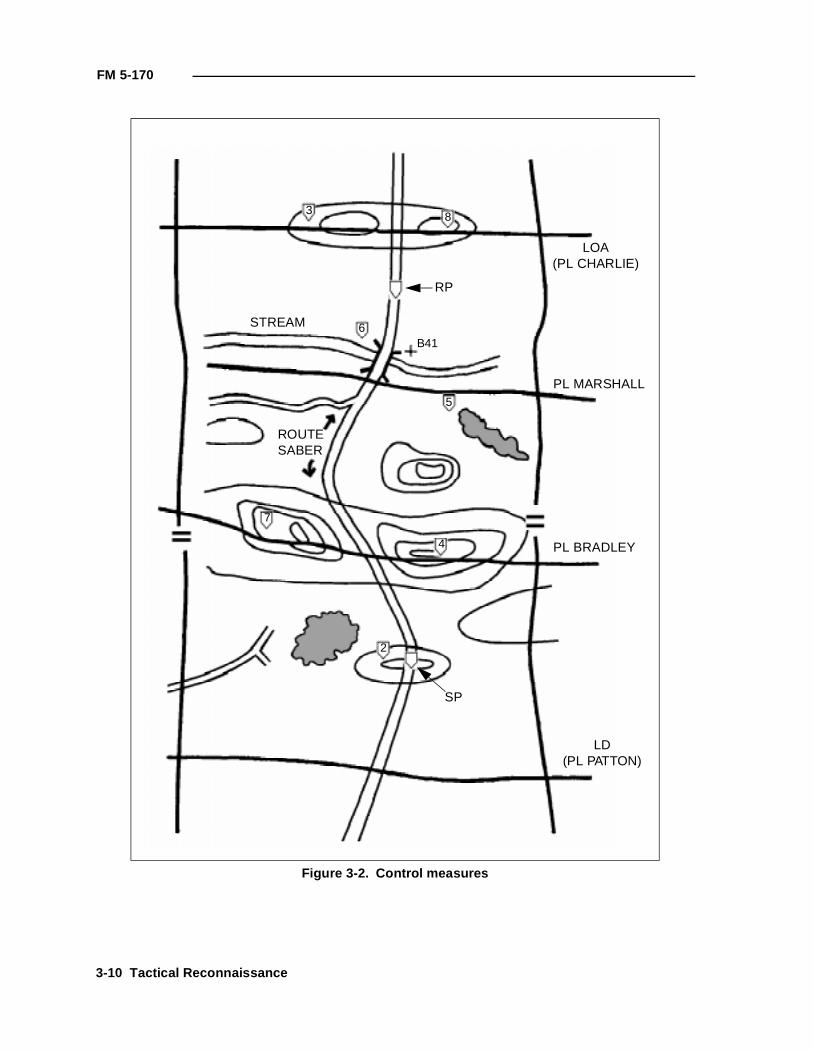
The scout platoon leader receives an order specifying the route the platoonmust recon and defining the route from start point (SP) to release point (RP).Additionally, the order may specify platoon boundaries, phase lines (PLs),lines of departure (LDs), and a limit of advance (LOA) or recon objective.These control measures specify how much terrain on both sides of a route thatthe platoon must recon and where the operation must begin and end. Theboundaries are drawn on both sides. They include the terrain that dominatesthe route, usually extending out 2.5 to 3 kilometers. This ensures that the
3-8 Tactical Reconnaissance
FM 5-170
scouts recon all terrain that the enemy could use to influence movement alongthe route. An LD is drawn from one boundary to the other behind the SP. Thisallows the platoon to cross the LD and be fully deployed before reaching theroute. An LOA or objective is placed beyond the RP on the last terrain featuredominating the route or out to about 3 kilometers (see Figure 3-2, page 3-10).
The recon platoon leader may add additional PLs, contact points, andcheckpoints to the graphics he receives from his commander. PLs are used tohelp control the platoon’s maneuver. The contact points ensure that the teamsmaintain contact at particular critical points. Checkpoints are used along aroute or on specific terrain to control movement or to designate areas thatmust be reconned. The engineer recon team leader should obtain thisinformation during the scout platoon OPORD briefing.
The recon platoon leader will also coordinate with the FSO and plan artillerytargets on known or suspected enemy positions and on dominant terrainthroughout the AO. The engineer recon team leader must ensure that thisinformation is included on his overlay.
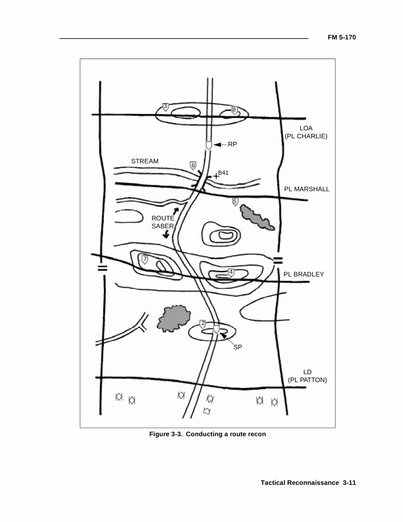
The recon platoon leader evaluates the METT-T factors and organizes hisplatoon with an engineer recon team to meet mission needs. He ensures thatat least one team is responsible for reconning a route. A three-teamorganization is usually the type best suited to recon a route. Team A reconsthe terrain left of the route, Team B covers the terrain right of the route, andTeam C and the engineer recon team recon the route and controls themovement of the other two teams. In this organization, the platoon leader'steam has specific responsibility to clear the route (see Figure 3-3, page 3-11).The engineer recon team’s tasks will likely include a technical recon of theroute (including bridge load classification and possible locations for employingSCATMINEs).
EXAMPLE OF A ROUTE RECON
The following example of a route recon is for a cavalry scout platoon with anengineer platoon attached.
When the scout platoon (with an engineer platoon) conducts a route recon, it oftendeploys in a V formation because of the mission’s focused nature. Team A ispositioned to the left of the route, Team B to the right, and Team C (with an engineerplatoon) in the center of the zone along Route Saber. The platoon should deploy intothe formation before reaching LD Patton so that it crosses the LD at the specified time.The platoon leader reports crossing the LD when the first element crosses it (seeFigure 3-4, page 3-12).
Tactical Reconnaissance 3-9
FM 5-170
Figure 3-2. Control measures
LOA(PL CHARLIE)
PL MARSHALL
PL BRADLEY
LD(PL PATTON)
STREAM
ROUTESABER
RP
SP
3 8
5
6B41
7
4
2
3-10 Tactical Reconnaissance
FM 5-170
Figure 3-3. Conducting a route recon
PL MARSHALL
PL BRADLEY
LD(PL PATTON)
STREAM
RP
SP
38
5
6B41
7
4
2
LOA(PL CHARLIE)
ROUTESABER
Tactical Reconnaissance 3-11
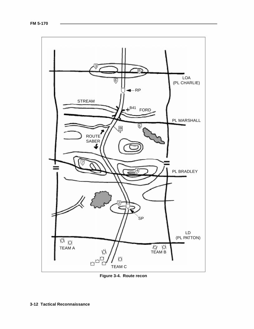
FM 5-170
Figure 3-4. Route recon
LOA(PL CHARLIE)
PL MARSHALL
PL BRADLEY
LD(PL PATTON)
STREAM
ROUTESABER
RP
SP
38
5
6
B41
7
4
2
B
FORD
TEAM A
TEAM C
TEAM B
3-12 Tactical Reconnaissance
FM 5-170
The scout platoon leader is responsible for movement through the zone. He usescheckpoints to control the movement and to focus on obstacles, key terrain, orfeatures that may influence movement along the route. The engineers focus onobstacles that must be located and cleared. Their efforts must focus on specific PIR toensure that the recon occurs in a timely manner.
Team C should be positioned along the route so that it can observe the route, and oneelement of the team must physically drive the entire route. Unless the sector is verysmall or very open, the platoon will move as individual teams. As the sections move tothe checkpoints, they maneuver in a zigzag pattern to clear the sector and accomplishall critical tasks of a route recon. The lead teams on the flanks must observe the routeand report any restrictions or obstacles that may restrict movement along the route.Visually clearing the route before Team C travels along it provides for better securityand allows Team C to concentrate on the critical recon tasks. As the teams maneuvertoward the checkpoints, they maintain visual contact with the route (see Figure 3-5,page 3-14).
After both lead teams report "Set" and are in overwatch positions, Team C begins theroute recon (see Figure 3-6, page 3-15). As the platoon leader moves along the route,his wingman maneuvers to provide overwatch for the platoon leader and the engineerplatoon. As the engineer platoon leader travels along Route Saber, he is normallyrequired to send a route classification of the trafficability at intervals designated by thecommander. A route report may be required only if there is a significant or unexpectedchange in the route's makeup.
As Team C clears the route, the other teams move ahead, clearing and reconningcritical and dominant terrain. The platoon leader controls and coordinates the teams’movements. He must ensure that the flank teams remain far enough forward of TeamC to provide security. The flank teams are also assigned responsibility for coveringlateral routes. Team A executes a lateral route and uses contact point B to tie withTeam C on Route Saber (see Figure 3-7, page 3-16).
The platoon order must address actions on the approach to the stream. In this case,the two flank teams have been given the task of locating bypasses in the form of fordsor unmapped bridges. Team B is successful in locating a ford; Team A is not. Theengineer platoon sends one squad to checkpoint 5, links up with Team B, andconducts a ford recon. Team B focuses on the steps used for obstacle and restrictionrecon and continues its mission (see Figure 3-8, page 3-17).
The engineer squad moves back to contact point B and links up with Team C and therest of the engineer platoon. Team C continues its route recon along the route until itapproaches the bridge site. It then executes a bridge recon to establish the bridge’strafficability. Team A occupies an overwatch position while Team C and the engineerplatoon recon the bridge. Team B continues its recon one terrain feature beyond thestream and then occupies a short-duration OP (see Figure 3-9, page 3-18).
Team C and the engineer platoon complete their bridge recon and establish localsecurity on the approaches to the bridge’s far side. The engineer platoon moves tocheckpoint 6 and observes the bridge during the crossing. Once completed, Team Apasses across the bridge and through Team C, continuing its recon to clear dominantterrain on the route’s left flank (see Figure 3-10, page 3-19). Once Team A is set, theplatoon resumes its route recon to the LOA (see Figure 3-11, page 3-20).
Tactical Reconnaissance 3-13
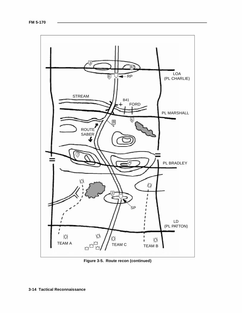
FM 5-170
Figure 3-5. Route recon (continued)
LOA(PL CHARLIE)
PL MARSHALL
PL BRADLEY
LD(PL PATTON)
STREAM
ROUTESABER
RP
SP
38
5
6
7
4
2
B
FORD
TEAM A TEAM C TEAM B
B41
3-14 Tactical Reconnaissance
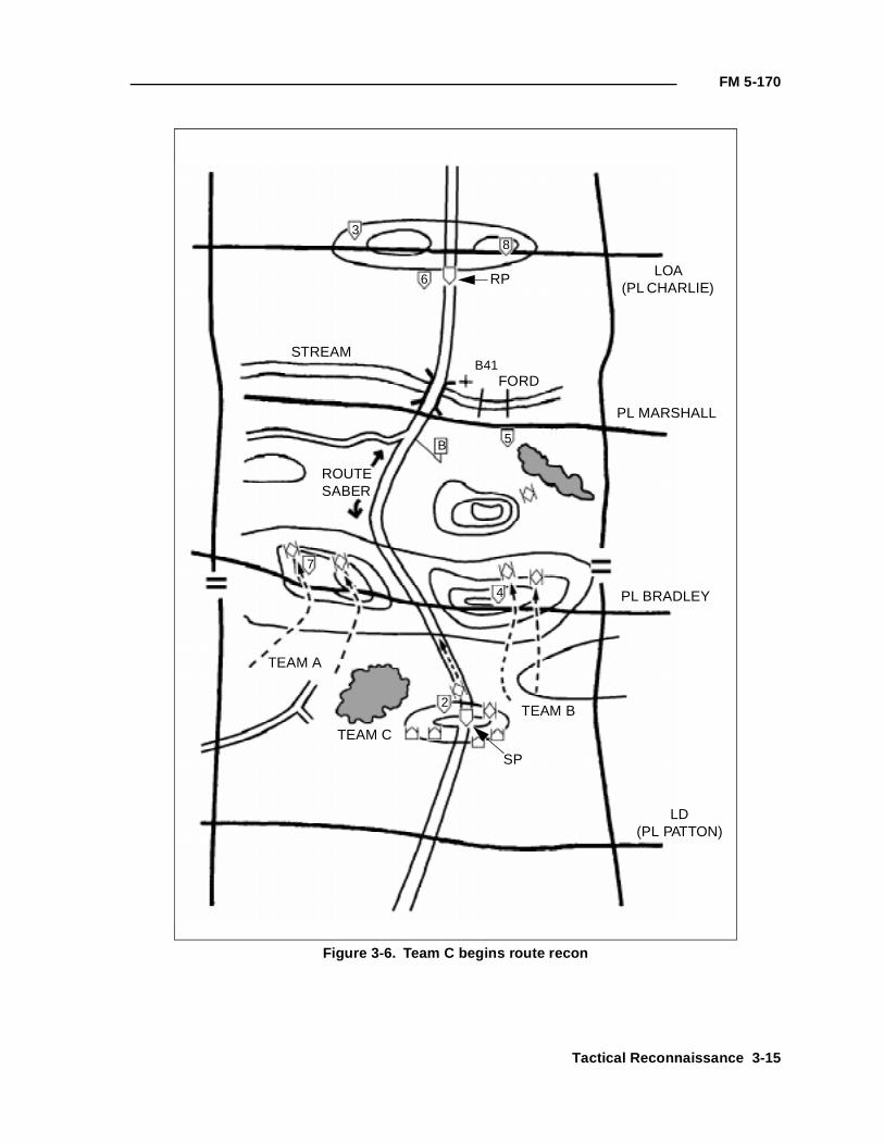
FM 5-170
Figure 3-6. Team C begins route recon
LOA(PL CHARLIE)
PL MARSHALL
PL BRADLEY
LD(PL PATTON)
STREAM
ROUTESABER
RP
SP
38
5
6
7
4
2
B
FORD
TEAM A
TEAM C
TEAM B
B41
Tactical Reconnaissance 3-15
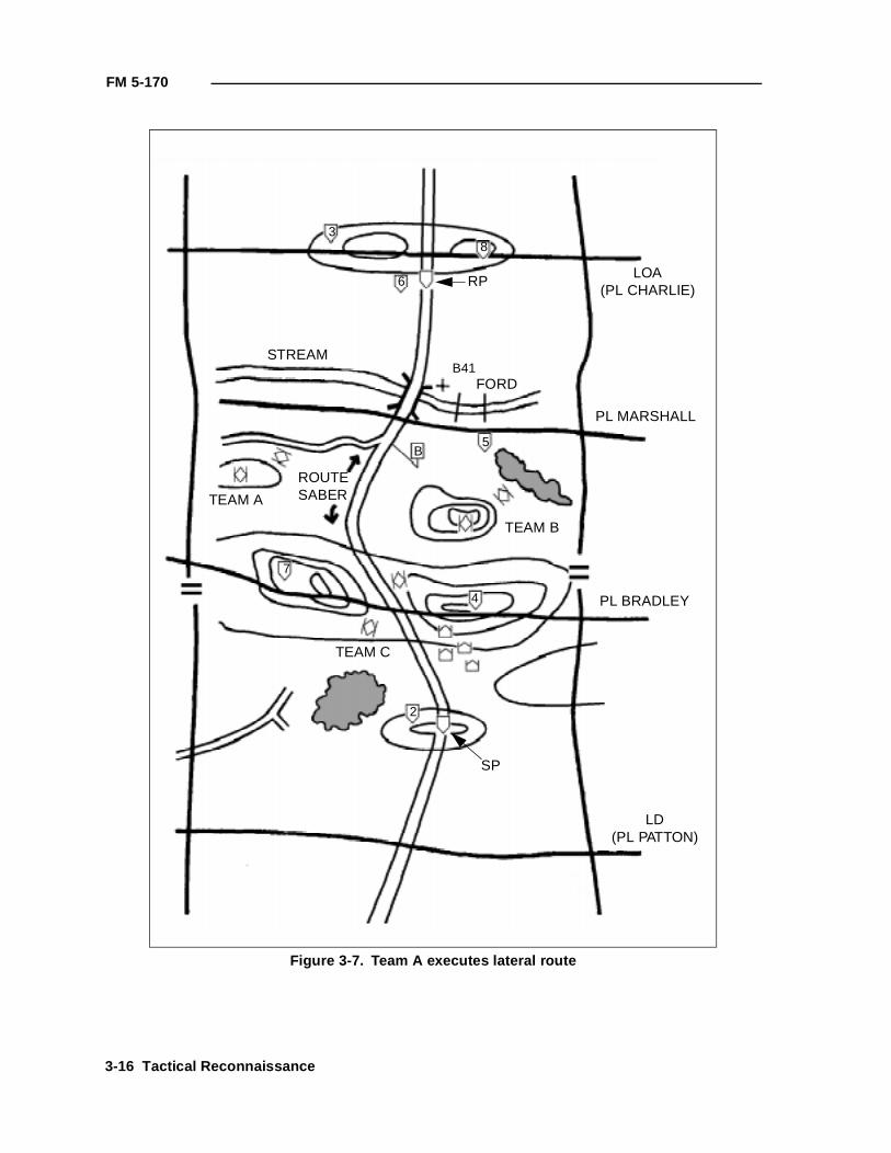
FM 5-170
Figure 3-7. Team A executes lateral route
LOA(PL CHARLIE)
PL MARSHALL
PL BRADLEY
LD(PL PATTON)
STREAM
ROUTESABER
RP
SP
38
5
6
7
4
2
B
FORDB41
TEAM A
TEAM B
TEAM C
3-16 Tactical Reconnaissance
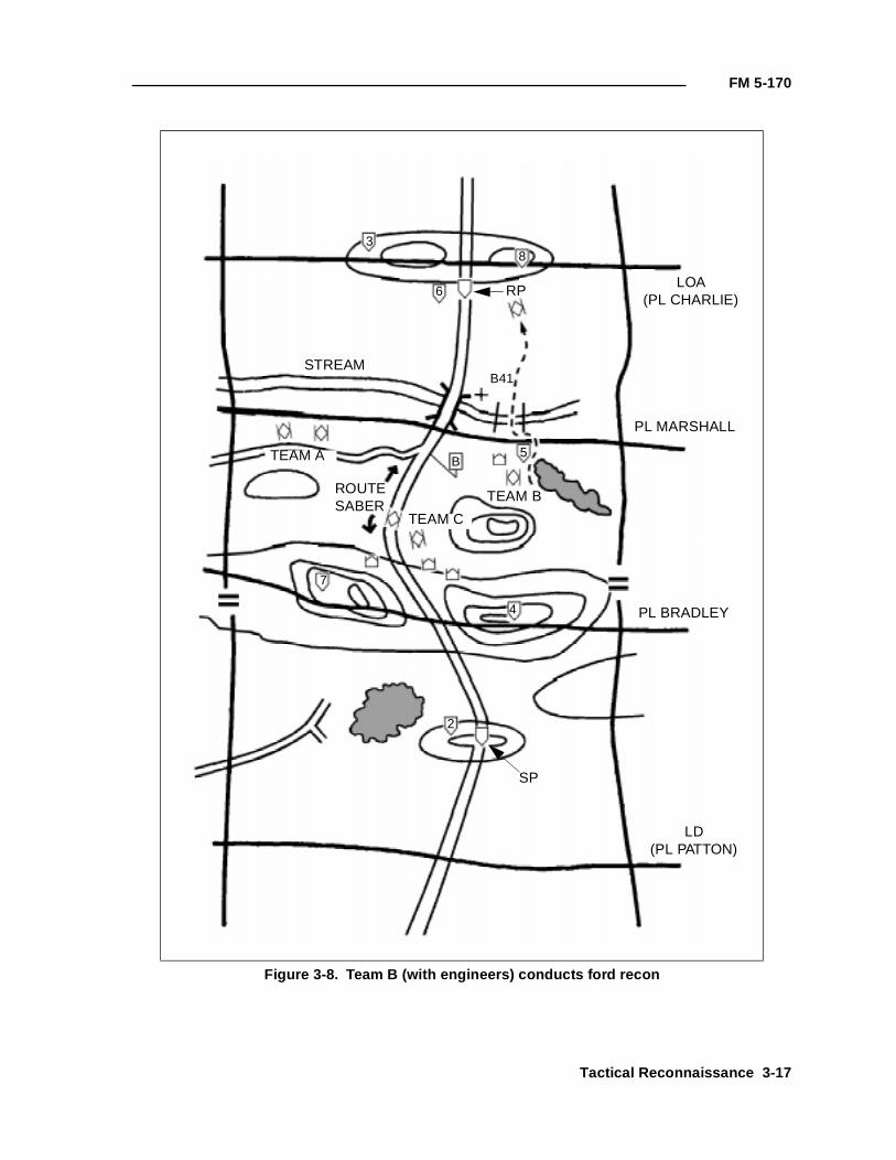
FM 5-170
Figure 3-8. Team B (with engineers) conducts ford recon
LOA(PL CHARLIE)
PL MARSHALL
PL BRADLEY
LD(PL PATTON)
STREAM
ROUTESABER
RP
SP
38
5
6
7
4
2
B
B41
TEAM B
TEAM C
TEAM A
Tactical Reconnaissance 3-17
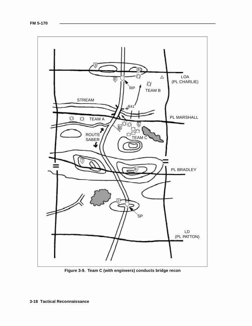
FM 5-170
Figure 3-9. Team C (with engineers) conducts bridge recon
LOA(PL CHARLIE)
PL MARSHALL
PL BRADLEY
LD(PL PATTON)
STREAM
ROUTESABER
RP
SP
38
5
6
7
4
2
B
B41
TEAM C
TEAM A
TEAM B
3-18 Tactical Reconnaissance
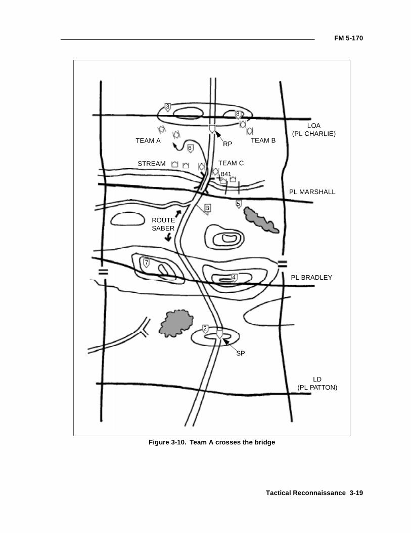
FM 5-170
Figure 3-10. Team A crosses the bridge
LOA(PL CHARLIE)
PL MARSHALL
PL BRADLEY
LD(PL PATTON)
STREAM
ROUTESABER
RP
SP
38
5
6
7
4
2
B
B41
TEAM C
TEAM A TEAM B
Tactical Reconnaissance 3-19
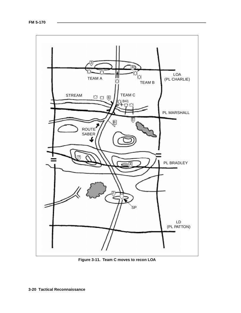
FM 5-170
Figure 3-11. Team C moves to recon LOA
LOA(PL CHARLIE)
PL MARSHALL
PL BRADLEY
LD(PL PATTON)
STREAM
ROUTESABER
SP
38
5
6
7
4
2
B
B41
TEAM C
TEAM ATEAM B
3-20 Tactical Reconnaissance
FM 5-170
ZONE RECON
Maneuver units and scouts, with the assistance of engineers, conduct zonerecon missions to gain detailed information about routes, terrain, resources,and enemy forces within a zone defined by lateral boundaries. Commandersnormally assign a zone recon mission when they need information beforesending their main-body forces through the zone. The recon producesinformation about the enemy situation and about routes and cross-countrytrafficability within the zone. Engineers play a primary role in obtaining routeand cross-country trafficability information. This is the most thorough andcomplete recon mission; therefore, it is very time intensive. It is common forscouts executing a zone recon with engineer assistance to advance at only 1.5kilometers per hour.
CRITICAL TASKS
During a zone recon, a recon element must accomplish a specified number oftasks unless directed to do otherwise. The recon leader must clearlyunderstand which of the following critical tasks must be accomplished:
• Reconning key terrain in the zone.
• Inspecting and classifying all key bridges within the zone.
• Locating suitable fording or crossing sites near all bridges within thezone.
• Inspecting and classifying all overpasses, underpasses, and culverts.
• Locating obstacles in the zone; determining how to reduce obstacles(assets and time) when needed. (Cavalry units may be required toclear the zone of obstacles. See FM 17-95.)
• Locating bypasses around built-up areas, obstacles, and contaminatedareas.
• Reporting enemy forces in the zone.
• Reporting recon information.
TECHNIQUES
A zone recon is a very time-consuming operation. Unless the orders specifyotherwise, all critical tasks listed above are implied in the zone recon missionstatement. Commanders who want a faster tempo of operations need tomodify the mission statement and ensure that the recon element knows whatits primary recon tasks are. For example, the TF commander may have criticalbridges that need classification to ensure that the main body can move withfreedom. However, he may have two other bridges within the zone that willnot be used by the TF and do not need to be classified.
Mounted maneuver units and TF scouts with engineers can effectively recon azone that is 3 to 5 kilometers wide. The zone’s width is determined by the roadnetwork, terrain features, anticipated enemy activity, and time available toaccomplish the mission. If the zone is wider than 3 to 5 kilometers, the reconelement quickly loses the capability to accomplish the critical tasks and movesecurely.
Tactical Reconnaissance 3-21
FM 5-170
When a recon leader receives a zone recon mission, the order will define thezone by lateral boundaries, an LD, and an LOA or objective. The parent unitmay include additional PLs or other graphic control measures within the zoneto help control the maneuver of the units.
The recon leader analyzes the mission to determine what must beaccomplished. He analyzes any information about the enemy during the IPBto determine what enemy activity he should expect to encounter. The engineercommander should work with the recon leader, the S2, and the S3 to ensurethat engineer recon tasks are identified and that enough engineers areattached to the recon element to accomplish the mission. The engineercommander will help analyze the terrain by—
• Assisting the S2 in map recon.
• Examining aerial photographs.
• Using an automated terrain-visualization tool.
Depending on the type of recon element, the experience of the attachedengineer recon team, and METT-T considerations, the element can conductthe zone recon using a two-, three-, or four-team organization. The reconelement must deploy to cover the entire zone. It usually operates in a zone itknows very little about, so the COA must allow for flexibility, responsiveness,and security as it moves. The recon leader deploys the scout teams on lineacross the LD. He uses PLs, checkpoints, contact points, or TIRS points toensure that the element recons the entire zone and that teams maintaincontact with each other. He ensures that scout teams remain generally on line,which prevents significant gaps that a moving enemy could exploit. Scoutsand engineers dismount as necessary to gather detailed information, cleardanger areas, or move through areas that are not accessible to the vehicles.The element continues to recon the zone until it reaches the LOA or the finalrecon objective.
EXAMPLE OF A ZONE RECON
The following example of a zone recon is for a battalion scout platoonaugmented with an engineer recon team.
Although strict formations are not generally used by scout platoons forward of theforward edge of the battle area (FEBA), the platoon leader in this example starts outwith his platoon on line. He will attempt to generally maintain this relationship eventhough the teams are not mutually supporting much of the time. The platoon shoulddeploy into formation before crossing the LD. In this example, Team A is on the left,Team B is on the right, and Team C is in the center of the zone (see Figure 3-12).
The platoon crosses the LD at the time prescribed in the commander's OPORD, usingthe bounding-overwatch technique of movement within the teams. In this mission, theplatoon leader has chosen to position himself and the engineers with Team A becauseof the importance of the route and bridge in Team A's AO. The teams maneuverthrough the zone in a zigzag pattern to ensure that the zone is properly reconned andto accomplish all critical tasks of a zone recon. Security is provided within teamsbecause the zone’s width and terrain prevent the teams from providing mutual support(see Figure 3-13, page 3-24).
3-22 Tactical Reconnaissance
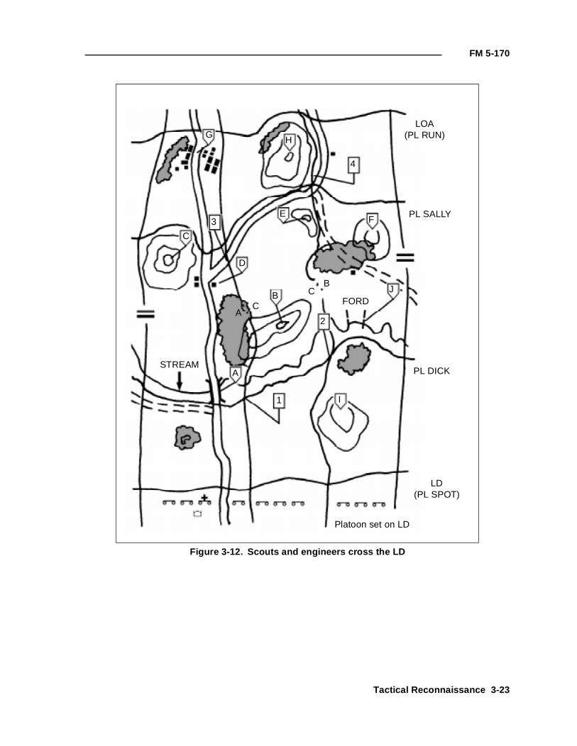
FM 5-170
Figure 3-12. Scouts and engineers cross the LD
GH
4
LOA(PL RUN)
PL SALLY
PL DICK
LD(PL SPOT)
3
C
D
E
B
F
J
2
I1
STREAMA
A
B
C
CFORD
Platoon set on LD
Tactical Reconnaissance 3-23
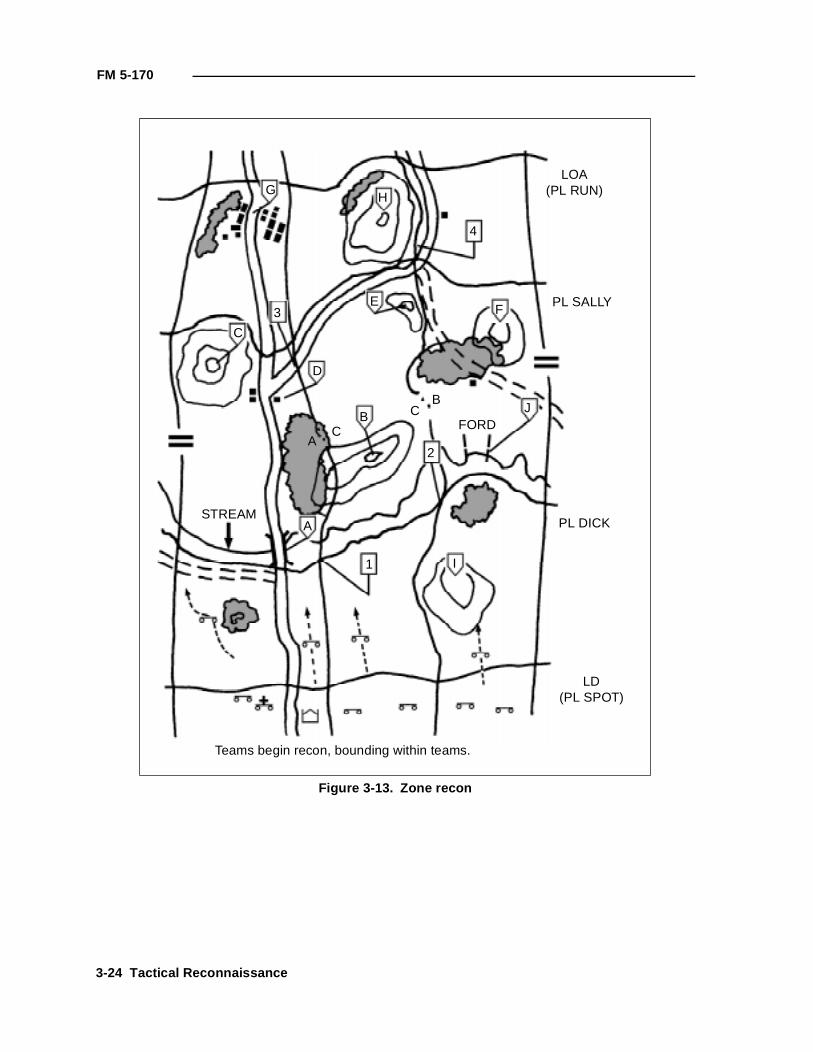
FM 5-170
Figure 3-13. Zone recon
GH
4
LOA(PL RUN)
PL SALLY
PL DICK
LD(PL SPOT)
3
C
D
E
B
F
J
2
I1
STREAMA
A
B
C
CFORD
Teams begin recon, bounding within teams.
3-24 Tactical Reconnaissance
FM 5-170
Depending on METT-T factors, the platoon leader chooses the movement techniquebest suited for C2. He may choose to have the teams clear and set at all checkpoints,or he may have them bound through the checkpoints, report clear, and then set at thePLs. If the platoon leader has not assigned teams a particular checkpoint to orient on,the team leaders must plan their own measures to control the movement. They moveteam elements to contact points to ensure that the move is tied in with that of the otherteams. The platoon leader does not allow any element to cross PL Dick until allelements have reported set (see Figure 3-14, page 3-26).
When the platoon is set on PL Dick, the leader gives the teams permission to executePL Dick and move to PL Sally. The teams immediately begin reconning the stream totheir front. Team A and the engineer recon team must execute a bridge recon andrecon the stream for possible unmarked fords. They must conduct a ford recon at theknown ford in zone.
Once Team C completes its recon of the stream and reports negative results, it movesto the vicinity of contact point 2 and awaits permission to cross the stream at Team B'sford. Team C is also prepared to cross at Team A's bridge, if necessary (see Figure3-15, page 3-27).
As Team A (with an engineer recon team) and Team B complete their recon tasks atthe bridge and ford, they revert to the bounding-overwatch movement technique andcontinue to recon. Team C moves across the team boundary and prepares to crossthe stream at the ford (see Figure 3-16, page 3-28).
The zone recon continues with Teams A and B clearing checkpoints D and F,respectively. The platoon leader holds the teams at those control measures to allowtime for Team C to clear checkpoint B and get on line with the other teams atcheckpoint E. This prevents dangerous gaps from developing between the teams (seeFigure 3-17, page 3-29).
Once Team C sets at checkpoint E, the platoon leader has all elements on line and setalong PL Sally. Teams A and C ensure that they make contact at contact point 3. Theplatoon leader gives permission for all elements to execute PL Sally and move to andset at PL Run (see Figure 3-18, page 3-30).
As the teams move across PL Sally, Teams B and C make contact at contact point 4.The platoon uses the bounding-overwatch technique within each team. The teamscontinue the zone recon in this manner, accomplishing all critical tasks and reportingall control measures and other recon information, until they reach the LOA or reconobjective (see Figure 3-19, page 3-31).
Tactical Reconnaissance 3-25
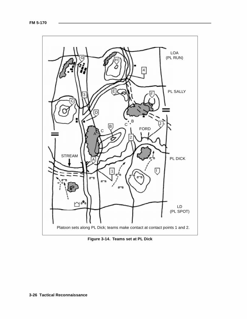
FM 5-170
Figure 3-14. Teams set at PL Dick
GH
4
LOA(PL RUN)
PL SALLY
PL DICK
LD(PL SPOT)
3
C
D
E
B
F
J
2
I1
STREAMA
A
B
C
CFORD
Platoon sets along PL Dick; teams make contact at contact points 1 and 2.
3-26 Tactical Reconnaissance
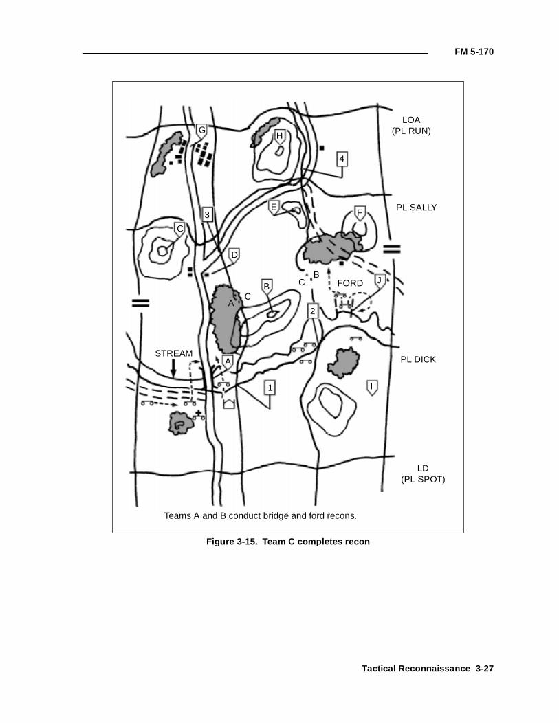
FM 5-170
Figure 3-15. Team C completes recon
GH
4
LOA(PL RUN)
PL SALLY
PL DICK
LD(PL SPOT)
3
C
D
E
B
F
J
2
I1
STREAMA
A
B
C
C FORD
Teams A and B conduct bridge and ford recons.
Tactical Reconnaissance 3-27
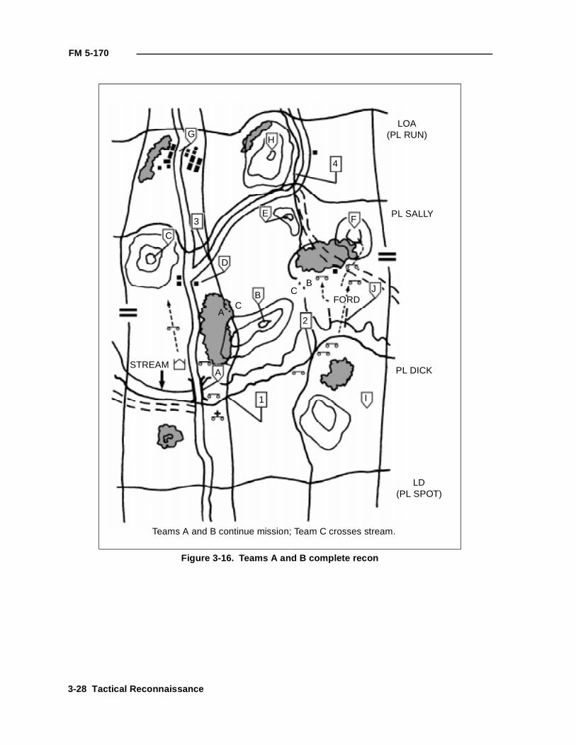
FM 5-170
Figure 3-16. Teams A and B complete recon
GH
4
LOA(PL RUN)
PL SALLY
PL DICK
LD(PL SPOT)
3
C
D
E
B
F
J
2
I1
STREAMA
A
B
C
CFORD
Teams A and B continue mission; Team C crosses stream.
3-28 Tactical Reconnaissance
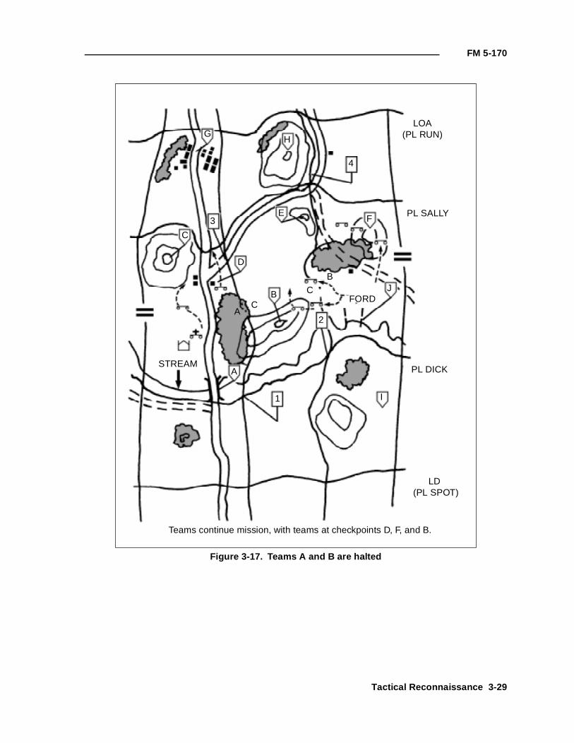
FM 5-170
Figure 3-17. Teams A and B are halted
GH
4
LOA(PL RUN)
PL SALLY
PL DICK
LD (PL SPOT)
3
C
D
E
B
F
J
2
I1
STREAMA
A
B
C
CFORD
Teams continue mission, with teams at checkpoints D, F, and B.
Tactical Reconnaissance 3-29
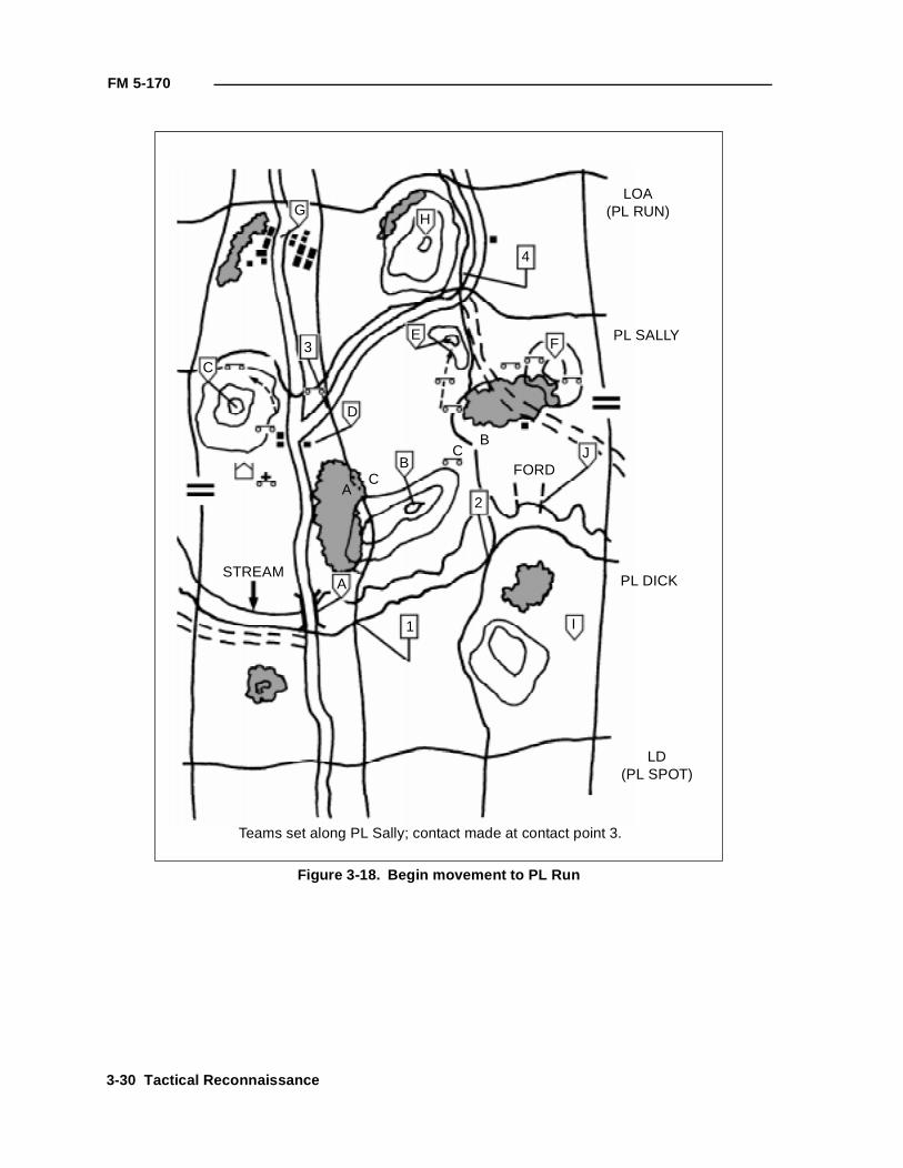
FM 5-170
Figure 3-18. Begin movement to PL Run
GH
4
LOA(PL RUN)
PL SALLY
PL DICK
LD(PL SPOT)
3C
D
E
B
F
J
2
I1
STREAMA
A
B
C
CFORD
Teams set along PL Sally; contact made at contact point 3.
3-30 Tactical Reconnaissance
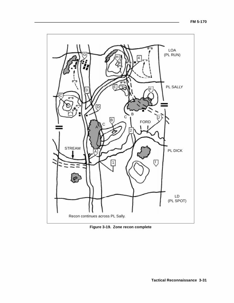
FM 5-170
Figure 3-19. Zone recon complete
GH 4
LOA(PL RUN)
PL SALLY
PL DICK
LD(PL SPOT)
3C
D
E
B
F
J
2
I1
STREAMA
A
B
C
CFORD
Recon continues across PL Sally.
Tactical Reconnaissance 3-31
FM 5-170
AREA RECON
Before moving forces into or near a specified area, commanders may call ontheir scouts or other recon element to conduct an area recon to avoid beingsurprised by unsuitable terrain conditions or unexpected enemy forces. Thearea could be a town, a ridgeline, woods, or other features that friendly forcesintend to occupy or pass through. Area recon is frequently required forobjective areas to confirm the IPB templates and provide detailed informationregarding enemy dispositions. In addition, area recon within a zone ofoperation can be used to focus the scouts on the specific area that is critical tothe commander. This technique of focusing the recon also permits the recon tobe accomplished more quickly. Therefore, an area recon can be a stand-alonemission or a task to a team or platoon within the larger context of a platoon ortroop recon mission.
CRITICAL TASKS
During an area recon, a recon element must accomplish a specified number oftasks unless directed to do otherwise. The recon leader must clearlyunderstand which of the following critical tasks must be accomplished:
• Reconning all terrain within the area.
• Inspecting and classifying all bridges within the area.
• Locating suitable fording or crossing sites near all bridges within thearea.
• Inspecting and classifying all overpasses, underpasses, and culverts.
• Locating obstacles in the area.
• Locating bypasses around built-up areas, obstacles, and contaminatedareas.
• Finding and reporting all enemy forces within the area. (Cavalry unitsmay be required to clear the area of obstacles. See FM 17-95.)
TECHNIQUES
The order to conduct an area recon mission identifies the area to be reconnedwithin a continuous boundary. A recon leader completes his troop-leadingprocedures using METT-T. He also plans the movement to and, if necessary,from the area, following the basic rule of using different routes in and out ofthe area. The routes are specified for the recon element when it works as partof a larger unit such as a cavalry troop. The element's primary concern duringmovement to the area is security rather than recon. During movement to thearea, it may be appropriate (depending on the commander's intent) for therecon element to avoid contact.
The recon leader encloses the given area within a zone; he uses boundaries, anLD, and an LOA. The recon leader can divide the area further by placingboundaries on identifiable terrain. This ensures that each team is responsiblefor specific terrain areas. The recon leader may also choose to orient and focusteams on checkpoints for both movement and recon. PLs may also be used tohelp control movement to the area. The recon leader places contact points atthe intersections of PLs and boundaries and any other places he wants
3-32 Tactical Reconnaissance
FM 5-170
physical contact and coordination between his teams. He uses TIRs asnecessary. He works with the FSO to plan indirect fires to support theelement's scheme of maneuver.
The recon leader deploys his teams abreast across the LD to accomplish theirrecon tasks. Formations are often not appropriate to this mission because ofthe irregular shape o f the area and the wide variety o f METT-Tconsiderations.
EXAMPLE OF AN AREA RECON
The following example of an area recon is for a battalion scout platoonaugmented by an engineer recon team.
The battalion scout platoon has been given the mission of performing an area recon ofObjectives Lead and Iron. The platoon has not been assigned a specific route, andenemy dispositions are vague.
The platoon leader analyzes the terrain and his mission requirements and decides touse a four-team organization. He assigns Teams A, B, and C checkpoints on ObjectiveIron. Because of Objective Lead's smaller size, he assigns only Team D to recon it.The platoon leader decides that he and the engineer recon team will move with TeamC to provide close control of the recon of Objective Iron. The platoon sergeant (PSG)will move with Team D and observe the recon of Objective Lead. The platoon leaderdecides to move the platoon using checkpoints that make maximum use of cover andconcealment between the LD and the objectives (see Figure 3-20, page 3-34).
Using the four-team organization, the platoon crosses PL Bob at the time specified inthe commander's OPORD. The platoon crosses in sequence, with the two lead teamsexecuting and the following teams waiting until initial checkpoints are cleared beforeproceeding. No platoon formation is used. The lead teams, which have the longestdistance to move to their recon objectives, use the bounding-overwatch technique toensure maximum security (see Figure 3-21, page 3-35).
As the lead teams execute checkpoints C and H, the trail teams cross the LD. Themovement technique is bounding overwatch within teams (see Figure 3-22, page3-36).
The scout teams continue their move to the designated dismount points. Team Doccupies its dismount point, checkpoint L. The team sets its vehicles in hide positions,organizes a patrol, and deploys local security (see Figure 3-23, page 3-37).
Team D's patrol moves on covered and concealed dismounted routes to ObjectiveLead and conducts a dismounted recon. The patrol uses the fan dismounted recontechnique to thoroughly recon the objective. Teams A and B occupy their dismountpoints (checkpoints A and D, respectively). Team C continues to move (see Figure3-24, page 3-38).
Team D's patrol completes its recon of Objective Lead. The team submits its reportand establishes an OP in the vicinity of checkpoint J from which it can observe theobjective area. Teams A and B dispatch their patrols to conduct dismounted recon onObjective Iron. The platoon leader has designated the checkpoints on the objective tofocus the team's patrol. Teams A and B recon checkpoints G and F, respectively. TeamC occupies its dismount point in the vicinity of checkpoint K (see Figure 3-25, page3-39).
Tactical Reconnaissance 3-33
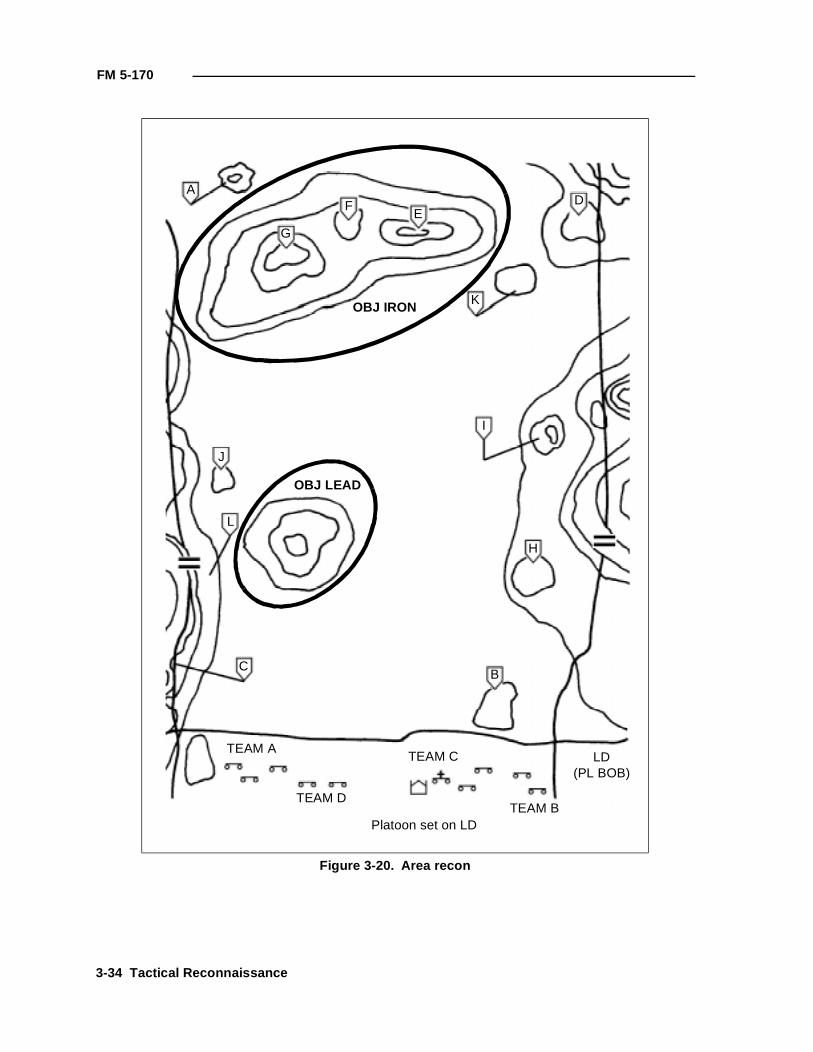
FM 5-170
Figure 3-20. Area recon
G
AF
E
K
I
H
J
L
CB
LD(PL BOB)
TEAM A
TEAM D
TEAM C
TEAM BPlatoon set on LD
OBJ IRON
OBJ LEAD
D
3-34 Tactical Reconnaissance
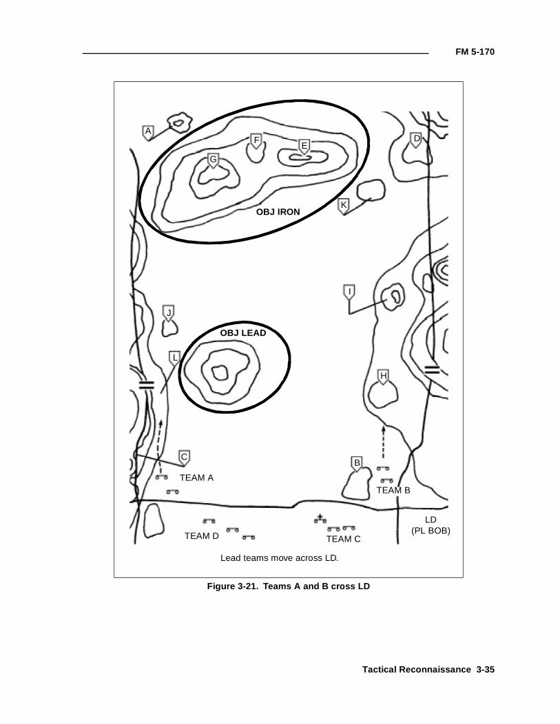
FM 5-170
Figure 3-21. Teams A and B cross LD
G
AF
E
K
I
H
J
L
CB
LD(PL BOB)
TEAM A
TEAM D TEAM C
TEAM B
Lead teams move across LD.
OBJ IRON
OBJ LEAD
D
Tactical Reconnaissance 3-35
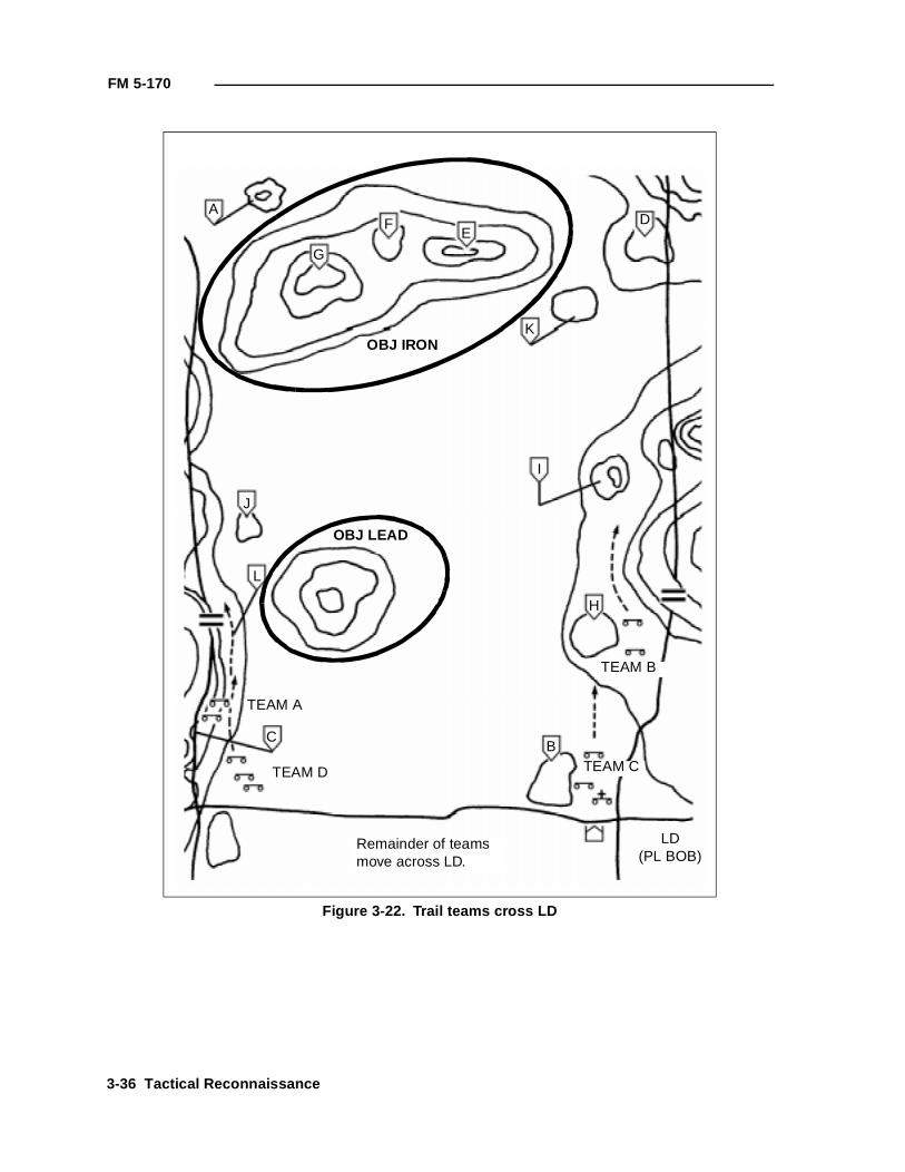
FM 5-170
Figure 3-22. Trail teams cross LD
G
AF
E
K
I
H
J
L
CB
LD(PL BOB)
TEAM A
TEAM D TEAM C
TEAM B
Remainder of teamsmove across LD.
OBJ IRON
OBJ LEAD
D
3-36 Tactical Reconnaissance
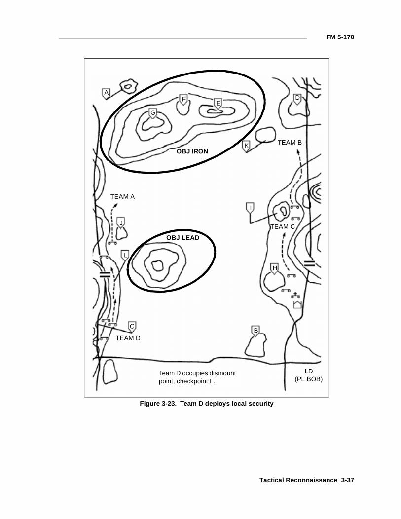
FM 5-170
Figure 3-23. Team D deploys local security
G
AF
E
K
I
H
J
L
CB
LD(PL BOB)
TEAM A
TEAM D
TEAM C
TEAM B
Team D occupies dismount point, checkpoint L.
OBJ IRON
OBJ LEAD
D
Tactical Reconnaissance 3-37
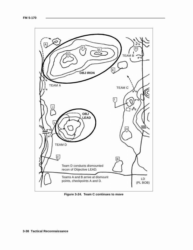
FM 5-170
Figure 3-24. Team C continues to move
G
AF
E
K
I
H
J
L
CB
LD(PL BOB)
TEAM A
TEAM D
TEAM C
TEAM B
Team D conducts dismounted recon of Objective LEAD.
Teams A and B arrive at dismount points, checkpoints A and D.
OBJ IRON
OBJLEAD
D
3-38 Tactical Reconnaissance
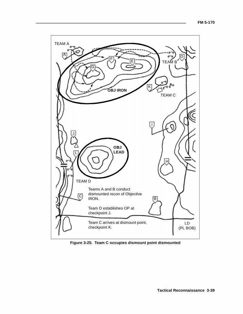
FM 5-170
Figure 3-25. Team C occupies dismount point dismounted
G
AF
E
K
I
H
J
L
CB
LD(PL BOB)
TEAM A
TEAM D
TEAM C
TEAM B
Teams A and B conduct dismounted recon of Objective IRON.
Team D establishes OP at checkpoint J.
Team C arrives at dismount point, checkpoint K.
OBJ IRON
OBJLEAD
D
Tactical Reconnaissance 3-39
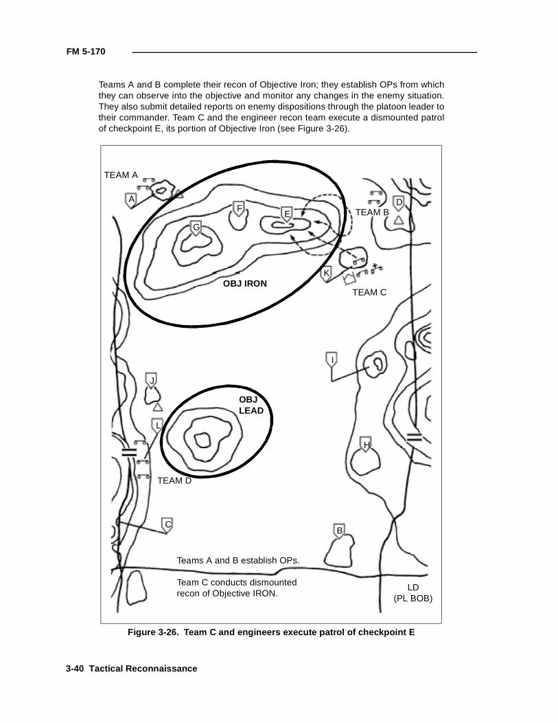
FM 5-170
Teams A and B complete their recon of Objective Iron; they establish OPs from whichthey can observe into the objective and monitor any changes in the enemy situation.They also submit detailed reports on enemy dispositions through the platoon leader totheir commander. Team C and the engineer recon team execute a dismounted patrolof checkpoint E, its portion of Objective Iron (see Figure 3-26).
Figure 3-26. Team C and engineers execute patrol of checkpoint E
G
AF
E
K
I
H
J
L
CB
LD(PL BOB)
TEAM A
TEAM D
TEAM C
TEAM B
Teams A and B establish OPs.
Team C conducts dismounted recon of Objective IRON.
OBJ IRON
OBJLEAD
D
3-40 Tactical Reconnaissance
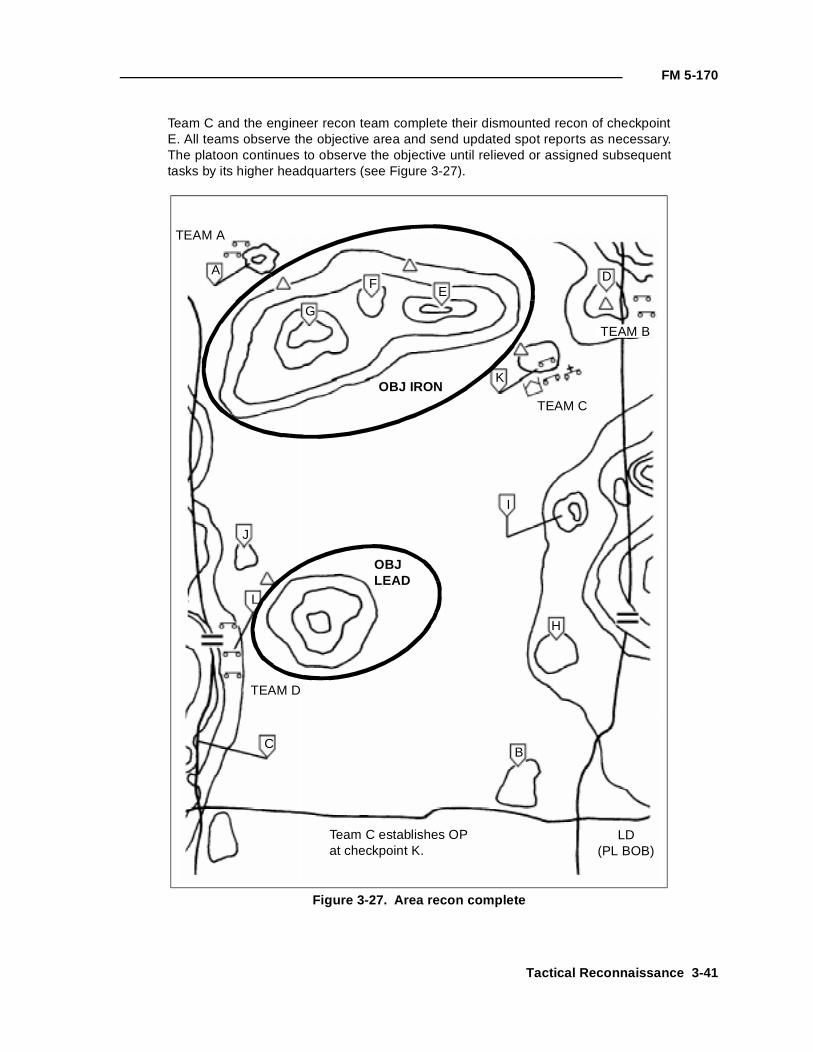
FM 5-170
Team C and the engineer recon team complete their dismounted recon of checkpointE. All teams observe the objective area and send updated spot reports as necessary.The platoon continues to observe the objective until relieved or assigned subsequenttasks by its higher headquarters (see Figure 3-27).
Figure 3-27. Area recon complete
G
AF
E
K
I
H
J
L
CB
LD(PL BOB)
TEAM A
TEAM D
TEAM C
TEAM B
Team C establishes OP at checkpoint K.
OBJ IRON
OBJLEAD
D
Tactical Reconnaissance 3-41
Chapter 4
Engineer Recon Team and Obstacle Reconnaissance
As discussed in Chapter 1, engineer recon elements may be a team-, asquad-, a platoon-, or another-sized element. Regardless of the size, highlytrained personnel are required for obstacle recon operations conductedforward of friendly lines and having extremely limited security andevacuation assets available. Engineer training must be focused onaccomplishing the specific obstacle recon mission.
The current engineer force structure does not provide for personnel (otherthan a recon noncommissioned officer [NCO] in the S2 section) orequipment dedicated to recon efforts. However, experience has shown thatengineer units that have dedicated personnel, equipment, and planningtime to the recon effort have achieved great success. Successfulemployment of engineers in a recon role is a result of effective SOPs andhighly trained staffs and recon teams. This chapter provides leaders withthe key factors required for the formation of engineer recon teams as wellas the C2 necessary when using engineer scouts.
PERSONNEL AND EQUIPMENT
Because an engineer battalion has limited assets to draw from, the formationof engineer recon teams can subsequently degrade the capabilities of theorganization from which they are drawn. The battalion commander mustunderstand the trade-offs between using engineer assets in a recon role versususing them in a maneuver-support role.
TRAINING
Regardless of where the personnel come from to create the engineer reconteams, units will have to dedicate a large amount of training time towarddeveloping an effective recon team. This training includes—
• Understanding how to apply the fundamentals of recon operations(see Chapter 3).
• Operating with brigade assets and the TF scouts in a habitualrelationship to develop the trust and familiarity necessary to succeedon the battlefield.
• Reporting, calling for fires, first aid, land navigation, demolitions,minefield indicators, foreign-mine recognition, dismounted-movementtechniques, vehicle and equipment maintenance, heliborne insertion,resupply, extraction, and relay and retrans procedures.
• Noise, light, and litter discipline and the using NVDs and camouflage.
• Rigorous physical training to meet mission requirements.
Engineer Recon Team and Obstacle Reconnaissance 4-1
FM 5-170
If the battalion leaders want to develop OBSTINTEL by using engineerscouts, adequate resources must be provided to ensure success.
EQUIPMENT
As with personnel, a decision must be made as to what equipment (vehicles,communications equipment, and weapon systems) the engineer recon teamswill use.
Vehicles
The most common recon vehicles used are the HMMWV or the M113A3 APC.Both vehicles have distinct advantages and disadvantages and can be usedeffectively by trained recon teams. The choice of vehicles must best supportthe teams in the environment for which they are expected to operate.Advantages of the HMMWV are that it is much more stealthy, is lessmaintenance intensive, and can travel in more restricted terrain than theM113A3. However, the M113A3 can carry more personnel and equipment(such as marking materials and mine detectors) and is more survivable. Bothvehicles can mount a weapon system such as the MK19 or the M2 machinegun. Another option available to engineer scouts is to ride in the back of avehicle from the supported unit. This limits the engineer recon team’sflexibility and control over what recons it can conduct.
Communications Equipment
The radio configuration in a recon team’s vehicle depends on the availability ofradio equipment and the radio nets the recon team will operate/monitor. Therecon team should have a minimum of two radios in the vehicles; each vehicleshould have the necessary equipment to act as a retrans vehicle to furtherextend the range of the dismounted element’s radio system. In addition to thevehicle-mounted radio systems, each recon team should be resourced with onemanpack radio specifically designated for use by the dismounted element.Since a large amount of data is passed when reporting OBSTINTEL, an effortshould be made to establish connectivity to recon teams through the use ofmobile subscriber equipment (MSE) or the Enhanced Position LocationReporting System (EPLRS) (as the system is fielded).
Weapon Systems
The M2 and the MK19 machine guns are available for mounting on anM113A3. The M2 provides greater range and rate of fire while the MK19 is anarea-fire weapon and may produce better effects on targets. Each recon teamshould also have at least one M203 and one squad automatic weapon (SAW) orM60 (as well as antiarmor weapons) available to it.
Additional Equipment
Each recon team should be supplied with night-vision capability, a GPS, ahand-held laser range finder, and a digital camera.
ENGINEER RECON TEAM
An engineer recon team is the base engineer recon element. The teamnormally recons one NAI or multiple NAIs within the same vicinity on thebattlefield. The battalion may employ more than one recon team if multiple
4-2 Engineer Recon Team and Obstacle Reconnaissance
FM 5-170
NAIs need to be observed in dispersed locations. In most instances, the reconteam will conduct its recon dismounted. However, the team may arrive in thevicinity of the recon objective in many ways, including dismounted or by air orground transportation. If the team travels dismounted or is air-inserted, itshould consist of at least three personnel. If the team uses an organic vehicleto arrive in the vicinity of its recon objective, it should consist of at least fivepersonnel—three with the dismounted element and two with the team’svehicle as the mounted element.
DISMOUNTED ELEMENT
A dismounted element consists of three or more personnel and is commandedby a recon team leader. The dismounted element’s mission is to locate andreport all necessary information required by the supported commanderaccording to the R&S plan. This information can be transmitted directly to thesupported unit’s headquarters on the appropriate net (according to the SOP orthe R&S order) or relayed through the mounted element.
MOUNTED ELEMENT
A mounted element consists of at least two personnel per vehicle—the vehicleoperator and an assistant recon team leader. The mounted element’s missionis to maintain communication with both the dismounted element and thesupported unit. The mounted element is responsible for relaying anyintelligence collected by the dismounted element to the appropriate C2 nodeand ensures that the team’s vehicle is not discovered by the enemy. (AllOBSTINTEL collected by a recon team is sent to the engineer battalion, ifpossible. A mobile subscriber radio telephone (MSRT) is normally the bestmethod.) The mounted element’s secondary mission is to be prepared to goforward and conduct the recon if the dismounted element is unsuccessful.
OBSTACLE AND RESTRICTION RECON
One of the high-frequency tasks associated with recon missions is locating andreconning obstacles and restrictions that may affect the trafficability along aroute or an axis. The purpose of this recon is to determine how best toovercome the effects of the obstacle: reduction or bypass. Tasks associatedwith this recon may be to estimate the reduction assets necessary to reducethe obstacle, to mark the best location to reduce, or to bypass the obstacle. Ifthe obstacle is to be bypassed, the recon team should be prepared to provideguides. Obstacles and restrictions are either existing or reinforcing. Doctrineassociated with the former Soviet Union emphasizes the use of man-madeobstacles to reinforce natural obstacles and restrictions to slow, impede, andcanalize friendly forces. These obstacles and restrictions include the following:
• Minefields.
• Bridges.
• Log obstacles.
• AT ditches.
• Wire entanglements.
• Defiles.
Engineer Recon Team and Obstacle Reconnaissance 4-3
FM 5-170
• Persistent agent contamination.
Although engineer recon teams have the capability to clear or reduce smallobstacles that are not covered by fire or observation, an engineer recon team’sprimary task is reconning tactical and protective obstacles. The recon shouldinclude supporting enemy positions and possible reduction sites. Anotherimportant task is locating and marking bypasses around obstacles andrestrictions.
Detection
During recon operations, engineers must help locate and evaluate obstaclesand man-made and natural restrictions to support the supported unit’smovement. Detecting obstacles and restrictions begins at the operation’splanning phase when the S2 and the engineer conduct the IPB. The scoutscombine the S2's work with the recon conducted during the troop-leadingprocess (normally a map recon only) to identify all possible obstacles andrestrictions within their AO. A recon team plans its recon based on the ordersit receives, the IPB, and its own map recon.
While assisting in a recon mission, engineers will use visual and physicalmeans to detect mines and obstacles. They visually inspect terrain for signs ofemplaced minefields and other reinforcing obstacles. They must be alert todangerous battlefield debris such as bomblets from cluster-bomb units (CBUs)or dual-purpose, improved conventional munitions (DPICM) and otherunexploded ordnances (UXOs). Minefields and other obstacles can be difficultto detect while mounted. Most obstacle detection occurs dismounted. Theengineer may dismount long distances from a suspected obstacle beforeconducting a recon. Engineer recon teams must carefully choose theirdismount point. Dismount points should be covered and concealed locationsout of direct-fire range of suspected enemy locations. Characteristics ofdismount points are that they—
• Afford cover and concealment.
• Are easy to defend for a short period of time.
• Are away from natural traffic flow.
• Are easy to locate.
• Are within close proximity to the objective to ease C2.
• Are out of sight, sound, and direct-fire range of the objective.
The engineer recon team should look for disturbed earth, unusual or out-of-place features, surface-laid mines, tilt rods, and trip wires. Maneuver unitsand scouts may assist in detecting mines by using the thermal sights in theirvehicles. Recon elements should conduct additional visual inspections toensure that the true extent of the obstacle is known.
Area Security and Recon
Enemy forces will cover their obstacles with observation and fire. When scoutsand engineer recon teams encounter an obstacle, they must assume the enemycan observe and engage them. The scout or engineer recon team that detectsthe obstacle establishes overwatch before it proceeds with the recon. The
4-4 Engineer Recon Team and Obstacle Reconnaissance
FM 5-170
overwatching element looks for signs of enemy forces in and around theobstacle. The element visually searches the dominant terrain on the obstacle’sfar side for evidence of enemy positions or ambushes. Once it confirms theenemy situation from the near side, the engineers and scouts (not inoverwatch) move mounted or dismounted to find bypasses around the obstacleand to establish OPs on the far side to provide 360-degree security of theobstacle. If the scouts and engineers are unable to find a bypass, they conducttheir recon from the near side under the security of the overwatch elements.
Obstacle Recon
Once security is established, scouts and engineers move dismounted to theobstacle using great caution. Trip wires and other wire may indicate that theenemy is using booby traps or command-detonated mines to prevent friendlyforces from determining the—
• Obstacle’s location and orientation.
• Types of mines in the minefield or the type of obstacle.
• Obstacle’s length and width.
• Existence of enemy coverage, including enemy strength, equipment,and fire support.
• Equipment necessary to reduce the obstacle.
The engineer recon team reconning the obstacle prepares an obstacle reportwith this information and forwards the report through the establishedchannels to the supported unit’s TOC.
COA Selection
After collecting the facts, the scout platoon/engineer recon team leaderanalyzes the situation and the METT-T factors to select a COA. There are fourCOAs: bypass, obstacle reduction, support of a deliberate breach, orcontinuing the mission.
Bypass
A bypass is the preferred method when it offers a quick, an easy, and atactically sound means of avoiding the obstacle. A good bypass must allow anentire force to avoid the primary obstacle without risking further exposure toenemy fires and without diverting the force from its objective. Bypassingconserves reduction assets and maintains the supported unit’s momentum. Ifa recon team locates a bypass and the commander approves its use, the scoutsand engineers must mark it according to the supported unit’s tactical SOP(TACSOP) and report it to their commander. At a minimum, this report shouldinclude the grid location to the far recognition marker and information on howthe obstacle is marked even if it is just to confirm that the bypass is markedaccording to the TACSOP. If the recon team is tasked to mark a bypass, theteam must emplace markers so they are not visible to the defending enemy.Engineers and scouts may be required to provide guides for the main body,especially if the bypass is difficult to locate or visibility conditions are poor.
Bypassing is not always possible, and breaching may be the best, or only,solution (such as in the following situations):
Engineer Recon Team and Obstacle Reconnaissance 4-5
FM 5-170
• The obstacle is integrated into a prepared defensive position, and theonly available bypass moves friendly forces into the fire sack orambush.
• The recon mission specifically tasks the recon team to clear theoriginal route for follow-on forces.
• The best available bypass route will not allow follow-on forces tomaintain their desired rate of movement, or it diverts the force fromthe objective.
• Improvements to the bypass may require more time and assets thanbreaching the primary obstacles.
Obstacle Reduction
Reducing an obstacle significantly degrades a recon team’s ability to maintainthe momentum of either the recon or the follow-on forces. Obstacles within thescout and engineer's ability to reduce include small minefields, simple wireobstacles, small roadblocks, and other similar obstacles. The supportedcommander should make the decision to have the recon team reduce anobstacle. The commander must consider the risk to the recon team and thepotential for prematurely identifying the force’s route. Obstacle reductionshould not be attempted if the obstacle is part of an integrated defensiveposition.
Support of a Breaching Operation
When a large obstacle is located and cannot be easily bypassed, thealternative is to support a breaching operation. Scouts and engineers performadditional recon tasks in support of the breaching operation. These tasksinclude determining the assets and time needed to reduce the obstacle and thelocation of the best reduction sites. Scout and engineer recon effort focuses onthe following:
• Trafficable routes to the reduction site and routes from the far sideleading to the objective.
• Proposed locations for positioning the support force.
• Dispersed, covered, and concealed areas near the reduction site.
• The best locations at the obstacle for reduction effort. It is imperativethat the reduction plan be sent to the recon teams once the scheme ofmaneuver is finalized. Information such as the number of lanesrequired and the distance between lanes will be needed for the reconforces to conduct the necessary recon.
• Positions on both sides of the obstacle that could provide enemyobservation of the reduction site.
• Trafficability and soil conditions near the reduction site. This isespecially important for minefield reduction because mine-clearingblades (MCBs) will not work properly in all soil conditions. This is alsoimportant information in support of river crossings. (See FM 90-13 forfurther details.)
• Soil type (loam, rocky, sandy, and so forth).
4-6 Engineer Recon Team and Obstacle Reconnaissance
FM 5-170
• The width, depth, and bottom conditions of wet and dry gaps andfords.
• The bank’s height and slope and soil stability of wet and dry gaps.
• The water velocity and direction of flow of wet gaps and fords.
• The wind direction for using smoke to obscure the enemy’s vision.
• The location of the forward edge of minefields to support MICLIC andMCB use.
This information can be obtained much easier if an engineer works closelywith the other recon elements, especially the TF scouts. An engineer reconteam must provide timely and valuable advice when large obstacles areencountered during a mission. The information is used by all elements of thebreaching operation to finalize the suppression, obscuration, security, andreduction (SOSR) plans for the breaching operation. The scouts help maintainsecurity and may call for and adjust indirect fires, as necessary, in support ofthe breaching operation.
COA Recommendation/Execution
Once the scouts and engineer recon teams have determined the best COA for asituation, they execute it or recommend it to higher headquarters forapproval. Generally, the recon team will execute a particular COA withoutspecific approval if it is addressed in the OPORD received from higherheadquarters or in the unit’s SOP. If the situation discovered is not covered byprevious guidance, the recon team determines the best COA and recommendsit to the commander before execution.
Examples of Obstacles/Restrictions
The following examples illustrate the recon of obstacles and restrictions in twotactical situations. They are organized using the five-step process (detection,area security and recon, obstacle recon, COA selection, and COArecommendation/execution).
Example 1: Reconning a Restriction (Not Covered by Fire or Observation)
Detection. The recon team detects a bridge when a dismounted element observes itfrom an overwatch position (see Figure 4-1, page 4-8). The bridge was expectedbecause it was also identified during the recon element's map recon. The dismountedelement confirms that the bridge is there and is intact.
Area Security and Recon. The dismounted scouts and engineers bring their vehiclesinto covered and concealed overwatch positions; the scouts establish near-sidesecurity of the bridge. A dismounted patrol with engineers is organized and conductsrecon up to the bridge while overwatched by the vehicles (see Figure 4-2, page 4-9).The dismounted element recons for both mounted and dismounted bypasses. It mustdetermine quickly if it is possible to bypass the bridge by using a ford in the local area.The recon leader monitors the situation and may direct other elements to assume themission of locating other bridges or fords to serve as bypasses, as necessary.
If the water obstacle can be forded, the dismounted scouts use the ford to move to thefar side. On the far side, they recon the terrain that dominates the bridge. Far-sidesecurity is established on terrain where they can observe enemy approach routes to
Engineer Recon Team and Obstacle Reconnaissance 4-7
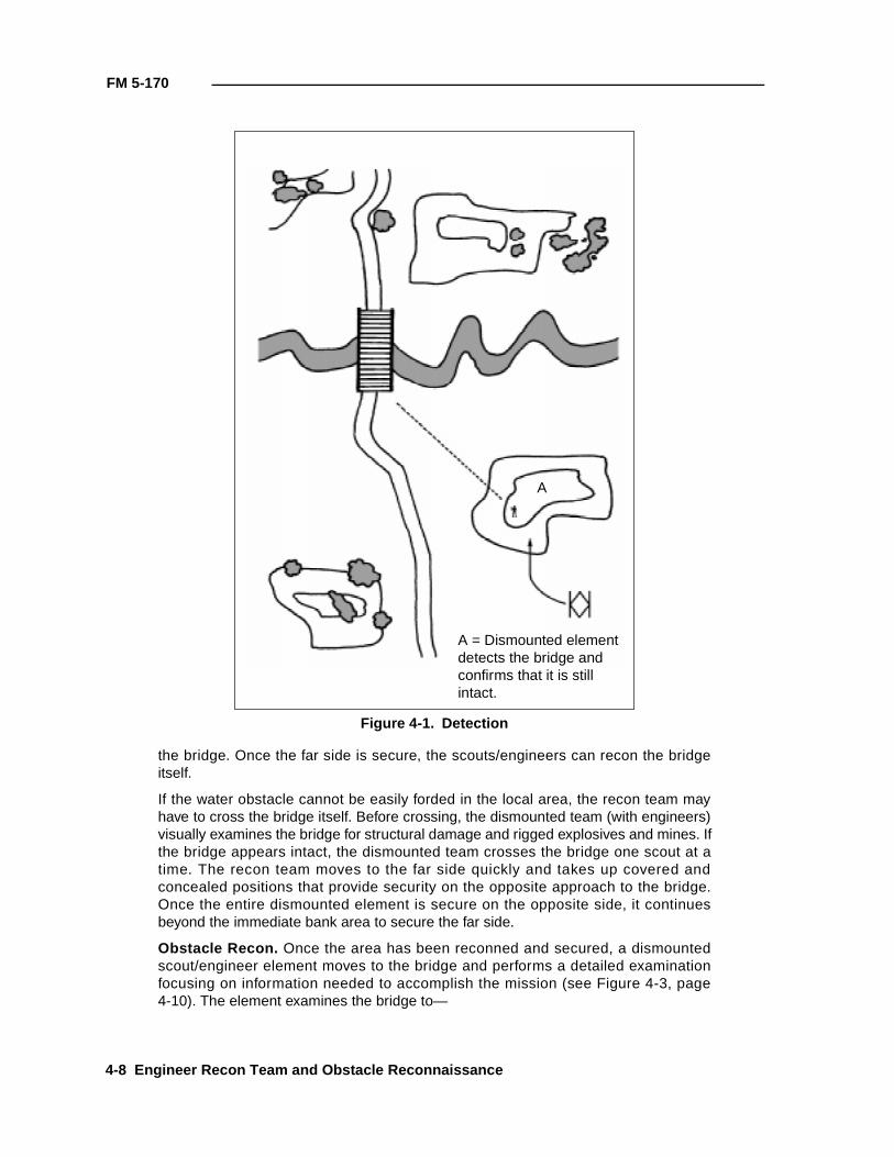
FM 5-170
the bridge. Once the far side is secure, the scouts/engineers can recon the bridgeitself.
If the water obstacle cannot be easily forded in the local area, the recon team mayhave to cross the bridge itself. Before crossing, the dismounted team (with engineers)visually examines the bridge for structural damage and rigged explosives and mines. Ifthe bridge appears intact, the dismounted team crosses the bridge one scout at atime. The recon team moves to the far side quickly and takes up covered andconcealed positions that provide security on the opposite approach to the bridge.Once the entire dismounted element is secure on the opposite side, it continuesbeyond the immediate bank area to secure the far side.
Obstacle Recon. Once the area has been reconned and secured, a dismountedscout/engineer element moves to the bridge and performs a detailed examinationfocusing on information needed to accomplish the mission (see Figure 4-3, page4-10). The element examines the bridge to—
Figure 4-1. Detection
A
A = Dismounted element detects the bridge and confirms that it is still intact.
4-8 Engineer Recon Team and Obstacle Reconnaissance
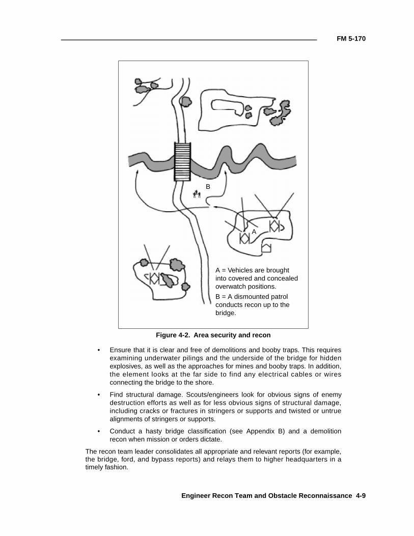
FM 5-170
• Ensure that it is clear and free of demolitions and booby traps. This requiresexamining underwater pilings and the underside of the bridge for hiddenexplosives, as well as the approaches for mines and booby traps. In addition,the element looks at the far side to find any electrical cables or wiresconnecting the bridge to the shore.
• Find structural damage. Scouts/engineers look for obvious signs of enemydestruction efforts as well as for less obvious signs of structural damage,including cracks or fractures in stringers or supports and twisted or untruealignments of stringers or supports.
• Conduct a hasty bridge classification (see Appendix B) and a demolitionrecon when mission or orders dictate.
The recon team leader consolidates all appropriate and relevant reports (for example,the bridge, ford, and bypass reports) and relays them to higher headquarters in atimely fashion.
Figure 4-2. Area security and recon
A = Vehicles are brought into covered and concealed overwatch positions.
B = A dismounted patrol conducts recon up to the bridge.
B
A
Engineer Recon Team and Obstacle Reconnaissance 4-9
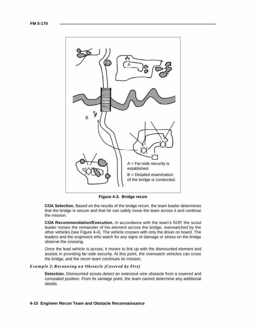
FM 5-170
COA Selection. Based on the results of the bridge recon, the team leader determinesthat the bridge is secure and that he can safely move the team across it and continuethe mission.
COA Recommendation/Execution. In accordance with the team’s SOP, the scoutleader moves the remainder of his element across the bridge, overwatched by theother vehicles (see Figure 4-4). The vehicle crosses with only the driver on board. Theleaders and the engineers who watch for any signs of damage or stress on the bridgeobserve the crossing.
Once the lead vehicle is across, it moves to link up with the dismounted element andassists in providing far-side security. At this point, the overwatch vehicles can crossthe bridge, and the recon team continues its mission.
Example 2: Reconning an Obstacle (Covered by Fire)
Detection. Dismounted scouts detect an extensive wire obstacle from a covered andconcealed position. From its vantage point, the team cannot determine any additionaldetails.
Figure 4-3. Bridge recon
A
B
A = Far-side security is established.
B = Detailed examination of the bridge is conducted.
4-10 Engineer Recon Team and Obstacle Reconnaissance
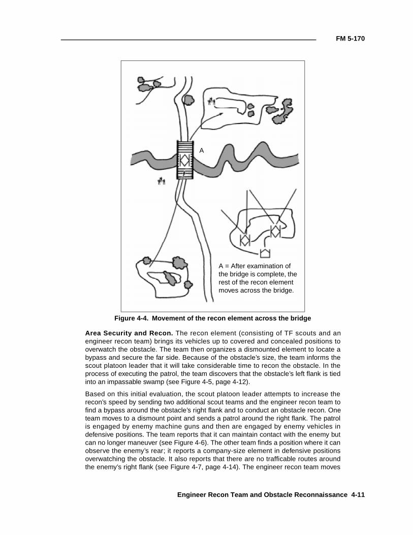
FM 5-170
Area Security and Recon. The recon element (consisting of TF scouts and anengineer recon team) brings its vehicles up to covered and concealed positions tooverwatch the obstacle. The team then organizes a dismounted element to locate abypass and secure the far side. Because of the obstacle’s size, the team informs thescout platoon leader that it will take considerable time to recon the obstacle. In theprocess of executing the patrol, the team discovers that the obstacle’s left flank is tiedinto an impassable swamp (see Figure 4-5, page 4-12).
Based on this initial evaluation, the scout platoon leader attempts to increase therecon’s speed by sending two additional scout teams and the engineer recon team tofind a bypass around the obstacle’s right flank and to conduct an obstacle recon. Oneteam moves to a dismount point and sends a patrol around the right flank. The patrolis engaged by enemy machine guns and then are engaged by enemy vehicles indefensive positions. The team reports that it can maintain contact with the enemy butcan no longer maneuver (see Figure 4-6). The other team finds a position where it canobserve the enemy’s rear; it reports a company-size element in defensive positionsoverwatching the obstacle. It also reports that there are no trafficable routes aroundthe enemy’s right flank (see Figure 4-7, page 4-14). The engineer recon team moves
Figure 4-4. Movement of the recon element across the bridge
A
A = After examination of the bridge is complete, the rest of the recon element moves across the bridge.
Engineer Recon Team and Obstacle Reconnaissance 4-11
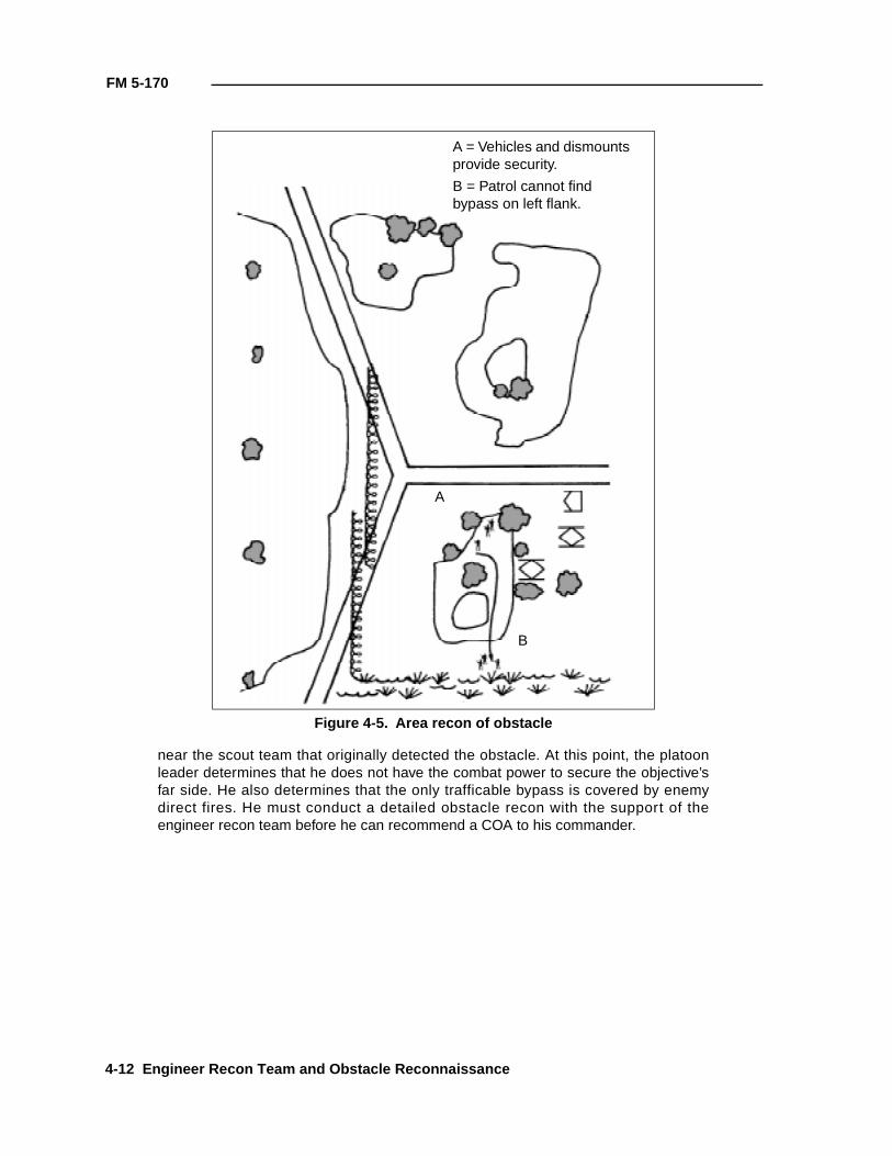
FM 5-170
near the scout team that originally detected the obstacle. At this point, the platoonleader determines that he does not have the combat power to secure the objective’sfar side. He also determines that the only trafficable bypass is covered by enemydirect fires. He must conduct a detailed obstacle recon with the support of theengineer recon team before he can recommend a COA to his commander.
Figure 4-5. Area recon of obstacle
A
B
A = Vehicles and dismounts provide security.
B = Patrol cannot find bypass on left flank.
4-12 Engineer Recon Team and Obstacle Reconnaissance
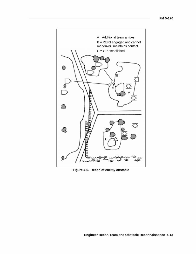
FM 5-170
Figure 4-6. Recon of enemy obstacle
A
B
C
A =Additional team arrives.
B = Patrol engaged and cannot maneuver; maintains contact.
C = OP established.
Engineer Recon Team and Obstacle Reconnaissance 4-13
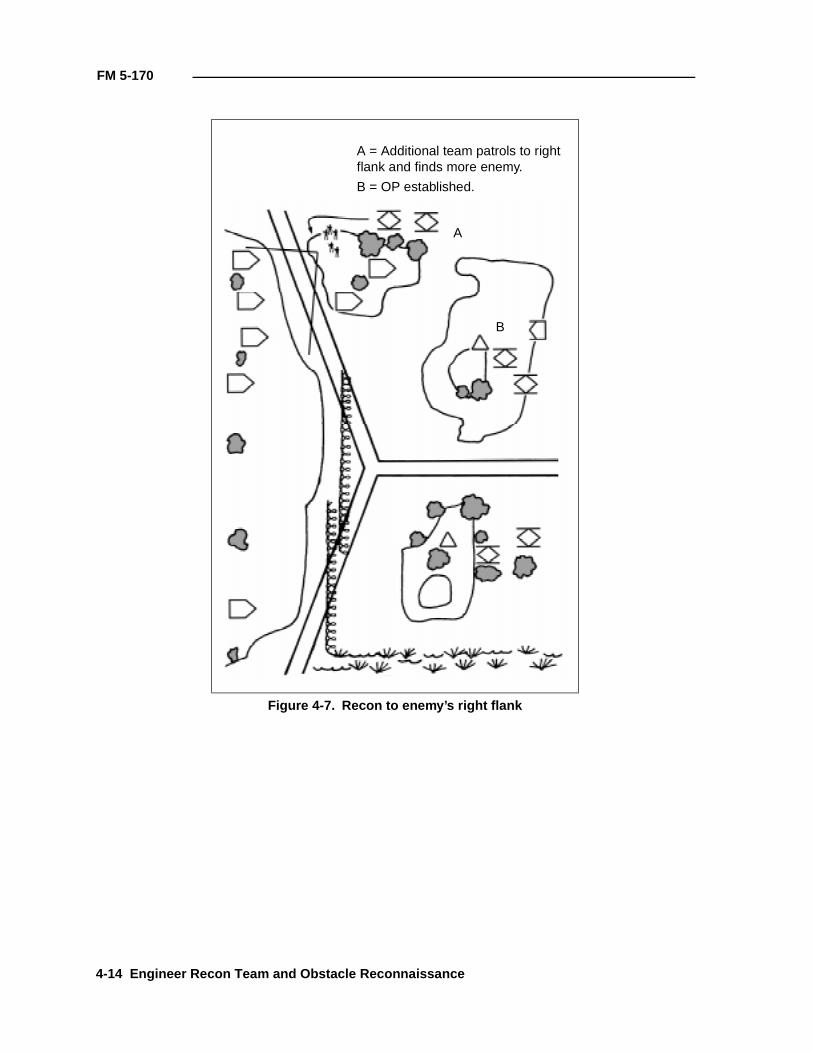
FM 5-170
Figure 4-7. Recon to enemy’s right flank
A
B
A = Additional team patrols to right flank and finds more enemy.
B = OP established.
4-14 Engineer Recon Team and Obstacle Reconnaissance
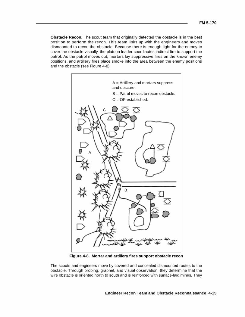
FM 5-170
Obstacle Recon. The scout team that originally detected the obstacle is in the bestposition to perform the recon. This team links up with the engineers and movesdismounted to recon the obstacle. Because there is enough light for the enemy tocover the obstacle visually, the platoon leader coordinates indirect fire to support thepatrol. As the patrol moves out, mortars lay suppressive fires on the known enemypositions, and artillery fires place smoke into the area between the enemy positionsand the obstacle (see Figure 4-8).
The scouts and engineers move by covered and concealed dismounted routes to theobstacle. Through probing, grapnel, and visual observation, they determine that thewire obstacle is oriented north to south and is reinforced with surface-laid mines. They
Figure 4-8. Mortar and artillery fires support obstacle recon
A
B
C
A = Artillery and mortars suppress and obscure.
B = Patrol moves to recon obstacle.
C = OP established.
Engineer Recon Team and Obstacle Reconnaissance 4-15
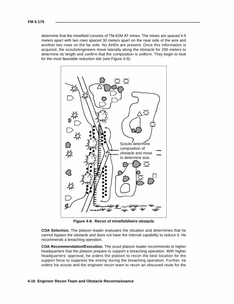
FM 5-170
determine that the minefield consists of TM-62M AT mines. The mines are spaced 4.5meters apart with two rows spaced 30 meters apart on the near side of the wire andanother two rows on the far side. No AHDs are present. Once this information isacquired, the scouts/engineers move laterally along the obstacle for 200 meters todetermine its length and confirm that the composition is uniform. They begin to lookfor the most favorable reduction site (see Figure 4-9).
COA Selection. The platoon leader evaluates the situation and determines that hecannot bypass the obstacle and does not have the internal capability to reduce it. Herecommends a breaching operation.
COA Recommendation/Execution. The scout platoon leader recommends to higherheadquarters that the platoon prepare to support a breaching operation. With higherheadquarters’ approval, he orders the platoon to recon the best location for thesupport force to suppress the enemy during the breaching operation. Further, heorders his scouts and the engineer recon team to recon an obscured route for the
Figure 4-9. Recon of minefield/wire obstacle
Scouts determine composition of obstacle and move to determine size.
4-16 Engineer Recon Team and Obstacle Reconnaissance
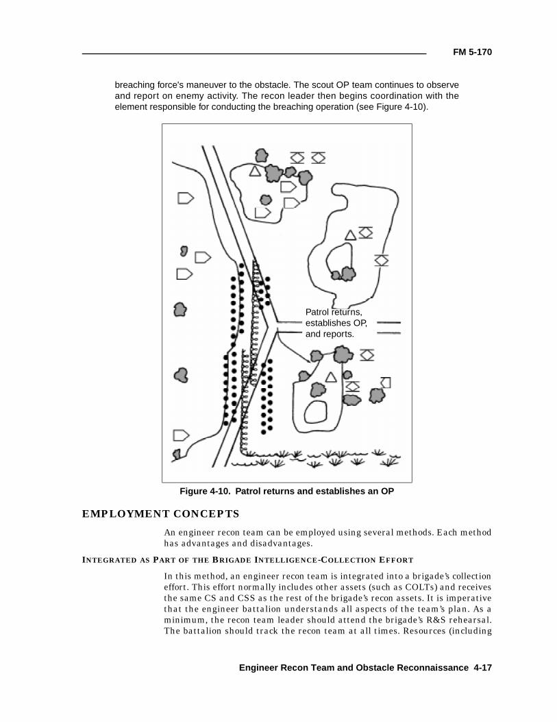
FM 5-170
breaching force's maneuver to the obstacle. The scout OP team continues to observeand report on enemy activity. The recon leader then begins coordination with theelement responsible for conducting the breaching operation (see Figure 4-10).
EMPLOYMENT CONCEPTS
An engineer recon team can be employed using several methods. Each methodhas advantages and disadvantages.
INTEGRATED AS PART OF THE BRIGADE INTELLIGENCE-COLLECTION EFFORT
In this method, an engineer recon team is integrated into a brigade’s collectioneffort. This effort normally includes other assets (such as COLTs) and receivesthe same CS and CSS as the rest of the brigade’s recon assets. It is imperativethat the engineer battalion understands all aspects of the team’s plan. As aminimum, the recon team leader should attend the brigade’s R&S rehearsal.The battalion should track the recon team at all times. Resources (including
Figure 4-10. Patrol returns and establishes an OP
Patrol returns, establishes OP, and reports.
Engineer Recon Team and Obstacle Reconnaissance 4-17
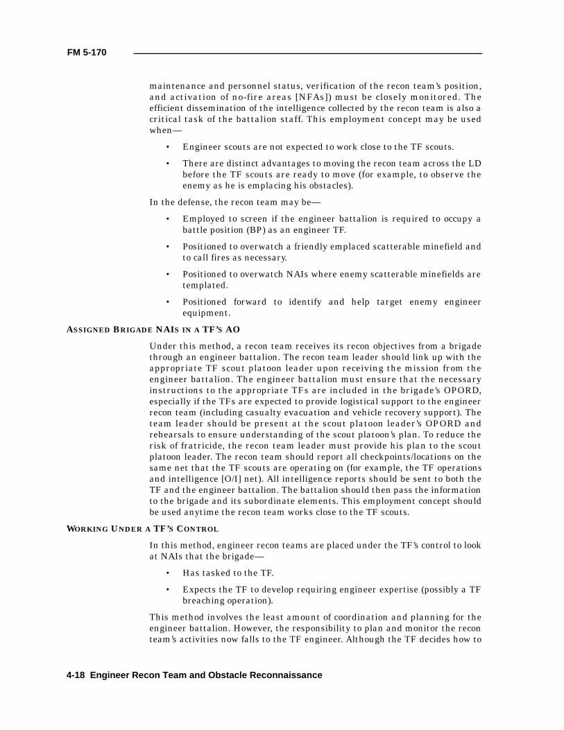
FM 5-170
maintenance and personnel status, verification of the recon team’s position,and activation of no-fire areas [NFAs]) must be closely monitored. Theefficient dissemination of the intelligence collected by the recon team is also acritical task of the battalion staff. This employment concept may be usedwhen—
• Engineer scouts are not expected to work close to the TF scouts.
• There are distinct advantages to moving the recon team across the LDbefore the TF scouts are ready to move (for example, to observe theenemy as he is emplacing his obstacles).
In the defense, the recon team may be—
• Employed to screen if the engineer battalion is required to occupy abattle position (BP) as an engineer TF.
• Positioned to overwatch a friendly emplaced scatterable minefield andto call fires as necessary.
• Positioned to overwatch NAIs where enemy scatterable minefields aretemplated.
• Positioned forward to identify and help target enemy engineerequipment.
ASSIGNED BRIGADE NAIS IN A TF’S AO
Under this method, a recon team receives its recon objectives from a brigadethrough an engineer battalion. The recon team leader should link up with theappropriate TF scout platoon leader upon receiving the mission from theengineer battalion. The engineer battalion must ensure that the necessaryinstructions to the appropriate TFs are included in the brigade’s OPORD,especially if the TFs are expected to provide logistical support to the engineerrecon team (including casualty evacuation and vehicle recovery support). Theteam leader should be present at the scout platoon leader’s OPORD andrehearsals to ensure understanding of the scout platoon’s plan. To reduce therisk of fratricide, the recon team leader must provide his plan to the scoutplatoon leader. The recon team should report all checkpoints/locations on thesame net that the TF scouts are operating on (for example, the TF operationsand intelligence [O/I] net). All intelligence reports should be sent to both theTF and the engineer battalion. The battalion should then pass the informationto the brigade and its subordinate elements. This employment concept shouldbe used anytime the recon team works close to the TF scouts.
WORKING UNDER A TF’S CONTROL
In this method, engineer recon teams are placed under the TF’s control to lookat NAIs that the brigade—
• Has tasked to the TF.
• Expects the TF to develop requiring engineer expertise (possibly a TFbreaching operation).
This method involves the least amount of coordination and planning for theengineer battalion. However, the responsibility to plan and monitor the reconteam’s activities now falls to the TF engineer. Although the TF decides how to
4-18 Engineer Recon Team and Obstacle Reconnaissance
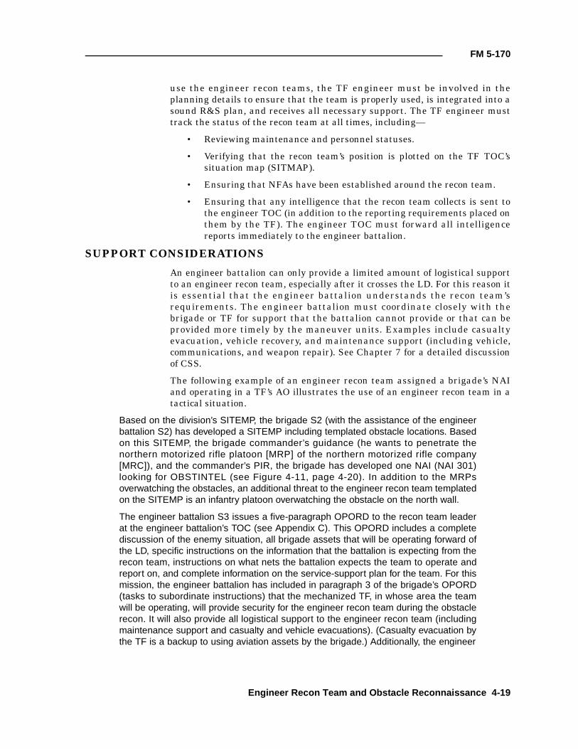
FM 5-170
use the engineer recon teams, the TF engineer must be involved in theplanning details to ensure that the team is properly used, is integrated into asound R&S plan, and receives all necessary support. The TF engineer musttrack the status of the recon team at all times, including—
• Reviewing maintenance and personnel statuses.
• Verifying that the recon team’s position is plotted on the TF TOC’ssituation map (SITMAP).
• Ensuring that NFAs have been established around the recon team.
• Ensuring that any intelligence that the recon team collects is sent tothe engineer TOC (in addition to the reporting requirements placed onthem by the TF). The engineer TOC must forward all intelligencereports immediately to the engineer battalion.
SUPPORT CONSIDERATIONS
An engineer battalion can only provide a limited amount of logistical supportto an engineer recon team, especially after it crosses the LD. For this reason itis essential that the engineer battalion understands the recon team’srequirements. The engineer battalion must coordinate closely with thebrigade or TF for support that the battalion cannot provide or that can beprovided more timely by the maneuver units. Examples include casualtyevacuation, vehicle recovery, and maintenance support (including vehicle,communications, and weapon repair). See Chapter 7 for a detailed discussionof CSS.
The following example of an engineer recon team assigned a brigade’s NAIand operating in a TF’s AO illustrates the use of an engineer recon team in atactical situation.
Based on the division’s SITEMP, the brigade S2 (with the assistance of the engineerbattalion S2) has developed a SITEMP including templated obstacle locations. Basedon this SITEMP, the brigade commander’s guidance (he wants to penetrate thenorthern motorized rifle platoon [MRP] of the northern motorized rifle company[MRC]), and the commander’s PIR, the brigade has developed one NAI (NAI 301)looking for OBSTINTEL (see Figure 4-11, page 4-20). In addition to the MRPsoverwatching the obstacles, an additional threat to the engineer recon team templatedon the SITEMP is an infantry platoon overwatching the obstacle on the north wall.
The engineer battalion S3 issues a five-paragraph OPORD to the recon team leaderat the engineer battalion’s TOC (see Appendix C). This OPORD includes a completediscussion of the enemy situation, all brigade assets that will be operating forward ofthe LD, specific instructions on the information that the battalion is expecting from therecon team, instructions on what nets the battalion expects the team to operate andreport on, and complete information on the service-support plan for the team. For thismission, the engineer battalion has included in paragraph 3 of the brigade’s OPORD(tasks to subordinate instructions) that the mechanized TF, in whose area the teamwill be operating, will provide security for the engineer recon team during the obstaclerecon. It will also provide all logistical support to the engineer recon team (includingmaintenance support and casualty and vehicle evacuations). (Casualty evacuation bythe TF is a backup to using aviation assets by the brigade.) Additionally, the engineer
Engineer Recon Team and Obstacle Reconnaissance 4-19

FM 5-170
battalion XO and S4 have directly contacted their counterparts at the TF to reinforceand confirm this support requirement.
The recon team leader immediately begins moving his team to the TF’s TOC where hehas coordinated a link up with the TF scout platoon leader. At the TOC, the teamleader ensures that the TF understands all the support elements on which thebattalion briefed him and that the S3 further briefs him on exactly how that support hasbeen planned. The team leader completes his OPORD as the assistant team leaderconducts the team’s precombat checks (PCCs). The leader’s plan calls for the team tocross the LD (PL Pistons) at 082000 JAN 97 and travel along Route Blue tocheckpoint 2, which he has designated as his dismount point. The recon team willobserve the NAI throughout the day on 9 JAN 97 in an effort to observe the enemyduring his obstacle emplacement. The team will link up with the TF scouts (who willprovide security for the team during the obstacle recon) at checkpoint 2 after endevening nautical twilight (EENT) on 9 JAN 97. At that point, the leader plans to travelwith the dismount element to the obstacle to conduct the recon. Two targets havebeen coordinated with the FSO in support of his mission—one in the vicinity of thedismount point and one in the vicinity of the templated obstacle. The team leader willestablish rally points from the dismount point to the obstacle. In the event that thedismount element becomes separated during contact with the enemy, it will meet atthe last established rally point (see Figure 4-12).
Before issuing his OPORD, the team leader will backbrief the engineer battalioncommander via frequency-modulated (FM) radio and will brief the scout platoonleader on his plan. The engineer recon team will cross the LD about 24 hours beforethe TF scouts in an attempt to observe the enemy as he emplaces his obstacles, whilethe TF is still developing its R&S plan. The team leader provides the scout PSG with
Figure 4-11. SITEMP with NAI 301
NAI301
4-20 Engineer Recon Team and Obstacle Reconnaissance
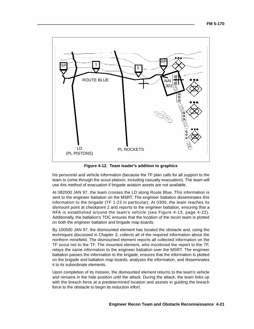
FM 5-170
his personnel and vehicle information (because the TF plan calls for all support to theteam to come through the scout platoon, including casualty evacuation). The team willuse this method of evacuation if brigade aviation assets are not available.
At 082000 JAN 97, the team crosses the LD along Route Blue. This information issent to the engineer battalion on the MSRT. The engineer battalion disseminates thisinformation to the brigade (TF 1-23 in particular). At 0300, the team reaches itsdismount point at checkpoint 2 and reports to the engineer battalion, ensuring that aNFA is established around the team’s vehicle (see Figure 4-13, page 4-22).Additionally, the battalion’s TOC ensures that the location of the recon team is plottedon both the engineer battalion and brigade map boards.
By 100500 JAN 97, the dismounted element has located the obstacle and, using thetechniques discussed in Chapter 3, collects all of the required information about thenorthern minefield. The dismounted element reports all collected information on theTF scout net to the TF. The mounted element, who monitored the report to the TF,relays the same information to the engineer battalion over the MSRT. The engineerbattalion passes the information to the brigade, ensures that the information is plottedon the brigade and battalion map boards, analyzes the information, and disseminatesit to its subordinate elements.
Upon completion of its mission, the dismounted element returns to the team’s vehicleand remains in the hide position until the attack. During the attack, the team links upwith the breach force at a predetermined location and assists in guiding the breachforce to the obstacle to begin its reduction effort.
Figure 4-12. Team leader’s addition to graphics
SP 12
RP
NAI 301
LD(PL PISTONS)
PL ROCKETS
ROUTE BLUE
Engineer Recon Team and Obstacle Reconnaissance 4-21
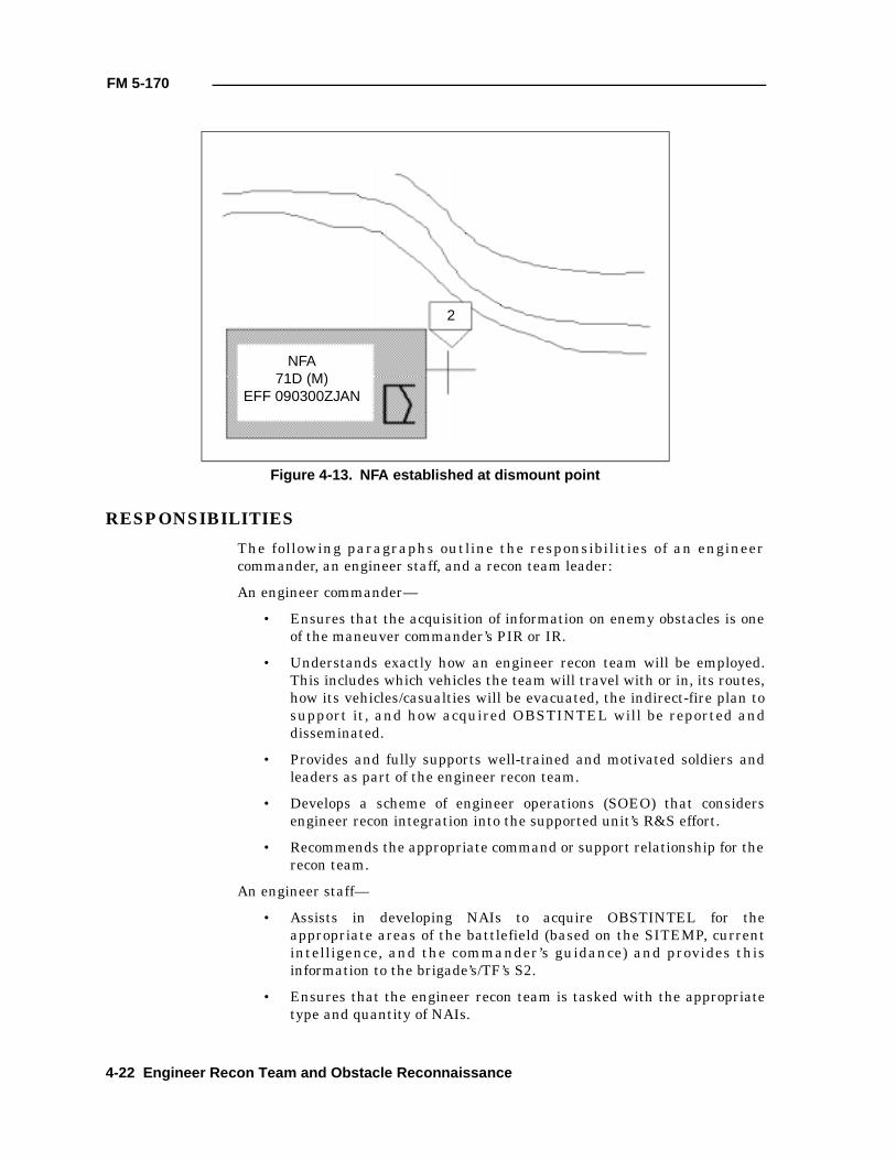
FM 5-170
RESPONSIBILITIES
The following paragraphs outline the responsibilities of an engineercommander, an engineer staff, and a recon team leader:
An engineer commander—
• Ensures that the acquisition of information on enemy obstacles is oneof the maneuver commander’s PIR or IR.
• Understands exactly how an engineer recon team will be employed.This includes which vehicles the team will travel with or in, its routes,how its vehicles/casualties will be evacuated, the indirect-fire plan tosupport it, and how acquired OBSTINTEL will be reported anddisseminated.
• Provides and fully supports well-trained and motivated soldiers andleaders as part of the engineer recon team.
• Develops a scheme of engineer operations (SOEO) that considersengineer recon integration into the supported unit’s R&S effort.
• Recommends the appropriate command or support relationship for therecon team.
An engineer staff—
• Assists in developing NAIs to acquire OBSTINTEL for theappropriate areas of the battlefield (based on the SITEMP, currentintelligence, and the commander’s guidance) and provides thisinformation to the brigade’s/TF’s S2.
• Ensures that the engineer recon team is tasked with the appropriatetype and quantity of NAIs.
Figure 4-13. NFA established at dismount point
NFA71D (M)
EFF 090300ZJAN
2
4-22 Engineer Recon Team and Obstacle Reconnaissance
FM 5-170
• Develops a feasible CSS plan for the team. It conducts staffcoordination with the maneuver units, as required.
• Coordinates for fire support for the team.
• Issues a complete OPORD to the recon team leader. The OPORDshould include instructions on what the recon team should do ifcommunications are lost, actions if templated obstacles are not at theassigned NAI, and recon requirements for unexpected obstaclesdiscovered en route.
• Tracks the location and activities of the recon team at all times.
• Ensures that NFAs are established around the recon team when theybecome stationary for an extended period of time (for example, in theteam’s hide position).
• Ensures that the team’s location is plotted on the engineer andmaneuver map board at all times.
• Tracks, analyzes, and disseminates all reported OBSTINTEL (seeFigure 4-14, page 4-24).
• Refocuses the R&S plan when required.
A recon team leader—
• Accepts responsibility for all facets of the training and discipline of hismen, the maintenance and operation of his equipment, and theintegration of his team into the supported unit.
• Maintains communications throughout the mission and reports allinformation quickly and accurately.
• Ensures that the recon team conducts rehearsals and equipmentpreparations before each mission.
Engineer Recon Team and Obstacle Reconnaissance 4-23
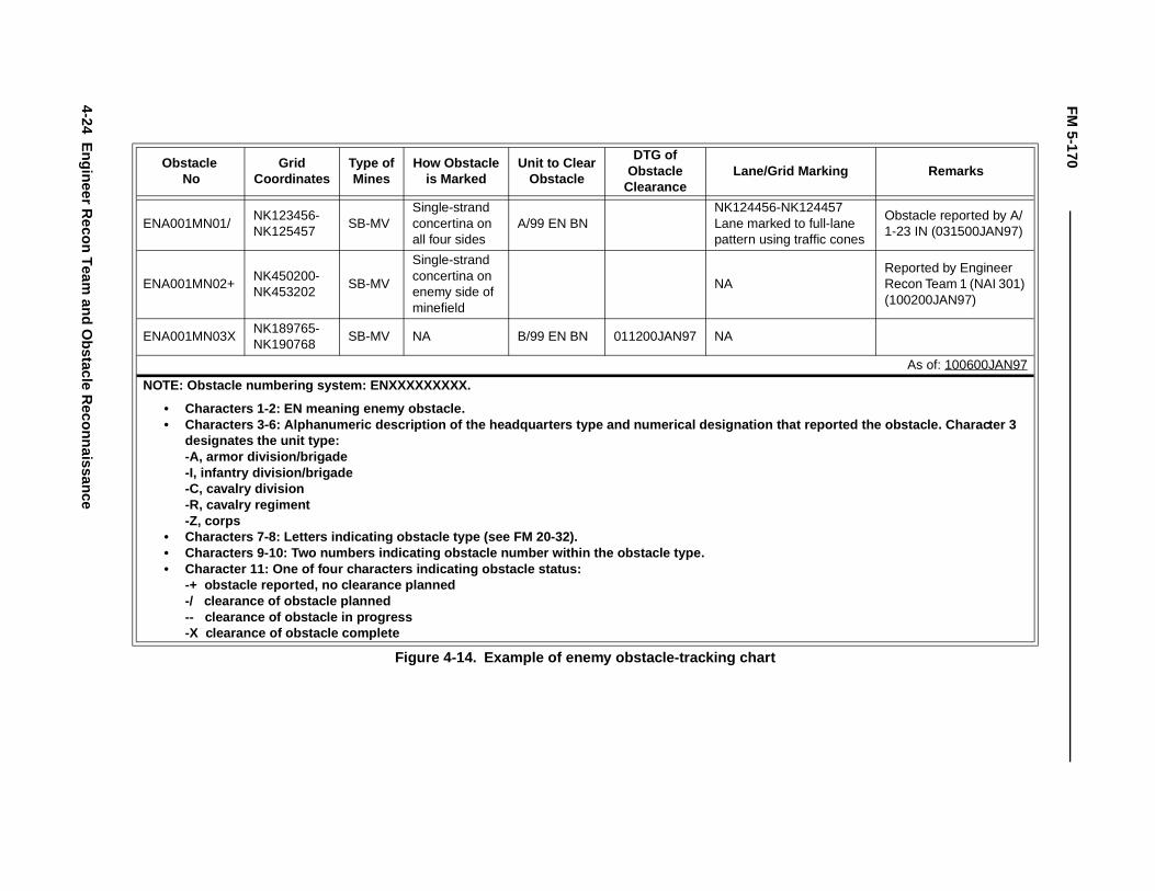
FM
5-170
4-24E
ngineer Recon T
eam and O
bstacle Reconnaissance
Lane/Grid Marking Remarks
K124456-NK124457 ane marked to full-lane attern using traffic cones
Obstacle reported by A/1-23 IN (031500JAN97)
AReported by Engineer Recon Team 1 (NAI 301) (100200JAN97)
A
As of: 100600JAN97
n that reported the obstacle. Charac ter 3
hart
Obstacle No
GridCoordinates
Type ofMines
How Obstacleis Marked
Unit to ClearObstacle
DTG ofObstacle
Clearance
ENA001MN01/NK123456-NK125457
SB-MVSingle-strand concertina on all four sides
A/99 EN BNNLp
ENA001MN02+NK450200-NK453202
SB-MV
Single-strand concertina on enemy side of minefield
N
ENA001MN03XNK189765-NK190768
SB-MV NA B/99 EN BN 011200JAN97 N
NOTE: Obstacle numbering system: ENXXXXXXXXX.
• Characters 1-2: EN meaning enemy obstacle.• Characters 3-6: Alphanumeric description of the headquarters type and numerical designatio
designates the unit type:-A, armor division/brigade-I, infantry division/brigade-C, cavalry division-R, cavalry regiment-Z, corps
• Characters 7-8: Letters indicating obstacle type (see FM 20-32).• Characters 9-10: Two numbers indicating obstacle number within the obstacle type.• Character 11: One of four characters indicating obstacle status:
-+ obstacle reported, no clearance planned-/ clearance of obstacle planned-- clearance of obstacle in progress-X clearance of obstacle complete
Figure 4-14. Example of enemy obstacle-tracking c
Chapter 5
Route Classification
This chapter describes how to perform the technical aspects of a routerecon. Route classification is a tool that helps determine what can traveldown a road network and how fast it may travel. Routes are reconned, andthe results are displayed on map overlays. During war or militaryoperations other than war (MOOTW), only the necessary and essentialfacts about a route are gathered as quickly and safely as possible. (Thisinformation is placed on a route-classification overlay and supplementedby additional reports.) During peacetime operations, detailed route-classification missions are performed to obtain in-depth information forfuture use.
Route classification may be conducted in a high-threat environment. Thesame tenets that guide tactical recons apply to technical recons. All reconsmust be coordinated with the supported unit. Combined-arms supportshould be planned and rehearsed to support the recon.
The first step in understanding the technical portions of a route recon isunderstanding what information is needed to complete a route-classification overlay.
ROUTE-CLASSIFICATION OVERLAY
A route-classification overlay graphically depicts a route’s entire network ofroads, bridge sites, and so forth. (These items are reconned, and the datarecorded as support documentation for the complete route.) A routeclassification gives specific details on what obstructions will slow down aconvoy or maneuver force along a route. Engineers are the experts on routeclassification.
As a minimum, the following information will be included on the route-classification overlay (see Figure 5-1, page 5-2):
• The route-classification formula.
• The name, rank, and social security number (SSN) of the person incharge of performing the classification.
• The unit conducting the classification.
• The date-time group (DTG) that the classification was conducted.
• The map name, edition, and scale.
• Any remarks necessary to ensure complete understanding of theinformation on the overlay.
Route Classification 5-1
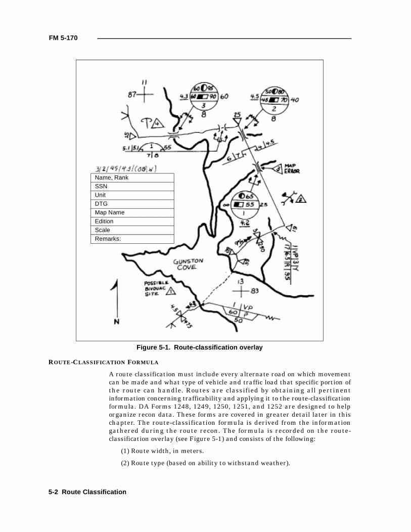
FM 5-170
ROUTE-CLASSIFICATION FORMULA
A route classification must include every alternate road on which movementcan be made and what type of vehicle and traffic load that specific portion ofthe route can handle. Routes are classified by obtaining all pertinentinformation concerning trafficability and applying it to the route-classificationformula. DA Forms 1248, 1249, 1250, 1251, and 1252 are designed to helporganize recon data. These forms are covered in greater detail later in thischapter. The route-classification formula is derived from the informationgathered during the route recon. The formula is recorded on the route-classification overlay (see Figure 5-1) and consists of the following:
(1) Route width, in meters.
(2) Route type (based on ability to withstand weather).
Figure 5-1. Route-classification overlay
Name, Rank
SSN
Unit
DTG
Map Name
Edition
Scale
Remarks:
5-2 Route Classification
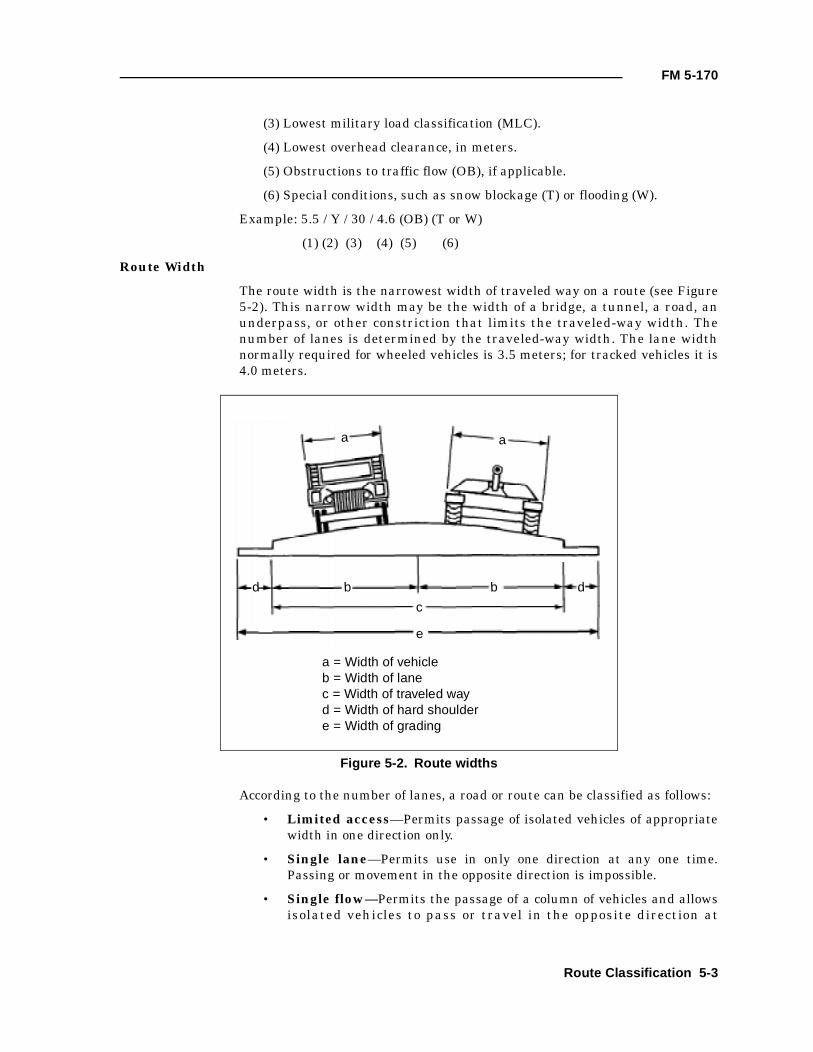
FM 5-170
(3) Lowest military load classification (MLC).
(4) Lowest overhead clearance, in meters.
(5) Obstructions to traffic flow (OB), if applicable.
(6) Special conditions, such as snow blockage (T) or flooding (W).
Example: 5.5 / Y / 30 / 4.6 (OB) (T or W)
(1) (2) (3) (4) (5) (6)
Route Width
The route width is the narrowest width of traveled way on a route (see Figure5-2). This narrow width may be the width of a bridge, a tunnel, a road, anunderpass, or other constriction that limits the traveled-way width. Thenumber of lanes is determined by the traveled-way width. The lane widthnormally required for wheeled vehicles is 3.5 meters; for tracked vehicles it is4.0 meters.
According to the number of lanes, a road or route can be classified as follows:
• Limited access—Permits passage of isolated vehicles of appropriatewidth in one direction only.
• Single lane—Permits use in only one direction at any one time.Passing or movement in the opposite direction is impossible.
• Single flow—Permits the passage of a column of vehicles and allowsisolated vehicles to pass or travel in the opposite direction at
Figure 5-2. Route widths
a a
b bd d
e
a = Width of vehicleb = Width of lanec = Width of traveled wayd = Width of hard shouldere = Width of grading
c
Route Classification 5-3
FM 5-170
predetermined points. It is preferable that such a route be at least 1.5lanes wide.
• Double flow—Permits two columns of vehicles to proceedsimultaneously. Such a route must be at least two lanes wide.
Route Type
The route type is determined by its ability to withstand weather. It isdetermined by the worst section of road on the entire route and is categorizedas follows:
• Type X—An all-weather route that, with reasonable maintenance, ispassable throughout the year to a volume of traffic never appreciablyless than its maximum capacity. This type of route is normally formedof roads having waterproof surfaces and being only slightly affected byrain, frost, thaw, or heat. This type of route is never closed because ofweather effects other than snow or flood blockage.
• Type Y—A limited, all-weather route that, with reasonablemaintenance, is passable throughout the year but at times having avolume of traffic considerably less than maximum capacity. This typeof route is normally formed of roads that do not have waterproofsurfaces and are considerably affected by rain, frost, thaw, or heat.This type of route is closed for short periods (up to one day at a time)by adverse weather conditions during which heavy use of the roadwould probably lead to complete collapse.
• Type Z—A fair-weather route passable only in fair weather. This typeof route is so seriously affected by adverse weather conditions that itmay remain closed for long periods. Improvement of such a route canonly be achieved by construction or realignment.
Military Load Classification
A route’s MLC is a class number representing the safe load-carrying capacityand indicating the maximum vehicle class that can be accepted under normalconditions. Usually, the lowest bridge MLC (regardless of the vehicle type orconditions of traffic flow) determines the route’s MLC. If there is not a bridgeon the route, the worst section of road will determine the route’s overallclassification.
In cases where vehicles have a higher MLC than the route, an alternate routemay be sought or an additional recon of the roads within the route may benecessary to determine whether a change in traffic flow (such as single-flowcrossing of a weak point) will permit heavier vehicles on the route. Whenpossible, ensure that the route network includes a number of heavy-trafficroads, as well as average-traffic roads. This helps staff planners manageheavy-traffic loads to decrease the bottleneck effect.
The entire network’s class is determined by the minimum load classification ofa road or a bridge within the network. These are the broad categories:
• Class 50—average-traffic route.
• Class 80—heavy-traffic route.
5-4 Route Classification
FM 5-170
• Class 120—very heavy-traffic route.
Overhead Clearance
The lowest overhead clearance is the vertical distance between the roadsurface and any overhead obstacle (power lines, overpasses, tunnels, and soforth) that denies the use of the road to some vehicles. Use the infinity symbol(∞) for unlimited clearance in the route-classification formula. (Points alongthe route where the minimum overhead clearance is less than 4.3 meters areconsidered to be an obstruction.)
Route Obstructions
Route obstructions restrict the type, amount, or speed of traffic flow. They areindicated in the route-classification formula by the abbreviation “OB.” If anobstruction is encountered, its exact nature must be depicted on the route-classification overlay. Obstructions include—
• Overhead obstructions such as tunnels, underpasses, overhead wires,and overhanging buildings with a clearance of less than 4.3 meters.
• Reductions in traveled-way widths that are below the standardminimums prescribed for the type of traffic flow (see Table 5-1). Thisincludes reductions caused by bridges, tunnels, craters, lanes throughmined areas, projecting buildings, or rubble.
• Slopes (gradients) of 7 percent or greater.
• Curves with a radius of 25 meters and less. Curves with a radius of25.1 to 45 meters are not considered to be an obstruction; however,they must be recorded on the route-recon overlay.
• Ferries.
• Fords.
Snow Blockage and Flooding
In cases where snow blockage is serious and is blocking traffic on a regularand recurrent basis, the symbol following the route-classification formula is“T.” In cases where flooding is serious and is blocking traffic on a regular andrecurrent basis, the symbol following the route-classification formula is “W.”
EXAMPLES OF THE ROUTE-CLASSIFICATION FORMULA
The following are examples depicting the use of the route-classificationformula:
• 6.1m/Z/40/∞—A fair-weather route (Z) with a minimum traveled wayof 6.1 meters, and an MLC of 40. Overhead clearance is unlimited (∞)and there are no obstructions to traffic flow. This route, based on its
Table 5-1. Traffic-flow capability based on route width
Limited Access
Single Lane
Single Flow
Double Flow
Wheeled At least 3.5 m 3.5 to 5.5 m 5.5 to 7.3 m Over 7.3 m
Tracked and combination vehicles At least 4.0 m 4.0 to 6.0 m 6.0 to 8.0 m Over 8 m
Route Classification 5-5
FM 5-170
minimum traveled-way width, accommodates both wheeled andtracked, single-flow traffic without obstruction.
• 6.1m/Z/40/∞ (OB)—A fair-weather route (Z) similar to the previousexample, except there is an obstruction. This obstruction could consistof overhead clearances of less than 4.3 meters, grades of 7 percent orgreater, curves with a radius of 25 meters and less, or fords andferries. A traveled way of 6.1 meters limits this route to one-way trafficwithout a width obstruction. If the route is used for double-flow traffic,then 6.1 meters of traveled way is considered an obstruction and isindicated in the formula as an obstruction.
• 7m/Y/50/4.6 (OB)—A limited, all-weather route (Y) with a minimumtraveled way of 7 meters, an MLC of 50, an overhead clearance of 4.6meters, and an obstruction. This route width is not suitable for double-flow traffic (wheeled or tracked). This width constriction is indicatedas OB in the route-classification formula if the route is used fordouble-flow traffic.
• 10.5m/X/120/∞ (OB) (W)—An all-weather route (X) with a minimumtraveled-way width of 10.5 meters, which is suitable for two-waytraffic of both wheeled and tracked vehicles; an MLC of 120; unlimitedoverhead clearance; an obstruction; and regular, recurrent flooding.
CURVE CALCULATIONS
The speed at which vehicles move along a route is affected by sharp curves.Curves with a radius of 25 meters and less are obstructions to traffic and areindicated by the abbreviation “OB” in the route-classification formula andidentified on DA Form 1248. Curves with a radius between 25.1 and 45 metersare recorded on the overlay but are not considered obstructions.
MEASURING METHODS
There are several ways to measure curves: the tape-measure, triangulation,and formula methods.
Tape-Measure Method
A quick way to estimate the radius of a sharp curve is by using a tape measureto find the radius (see Figure 5-3). Imagine the outer edge of the curve as theouter edge of a circle. Find (estimate) the center of this imaginary circle; thenmeasure the radius using a tape measure. Start from the center of the circleand measure to the outside edge of the curve. The length of the tape measurefrom the center of the imaginary circle to its outer edge is the curve’s radius.This method is practical for curves located on relatively flat ground andhaving a radius up to 15 meters.
Triangulation Method
You can determine a curve’s approximate radius by “laying out” right triangles(3:4:5 proportion) at the point of curvature (PC) and point of tangency (PT)locations (see Figure 5-4). The intersection (o), which is formed by extendingthe legs of each triangle, represents the center of the circle. The distance (R)from point o to either point PC or PT represents the curve’s radius.
5-6 Route Classification
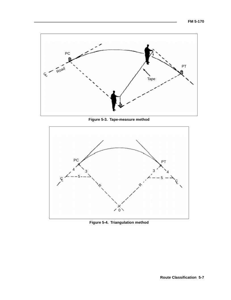
FM 5-170
Figure 5-3. Tape-measure method
Figure 5-4. Triangulation method
PC
Road
Tape
PT
C L
PC PT
C L C LR R
0
4433
5 5
Route Classification 5-7
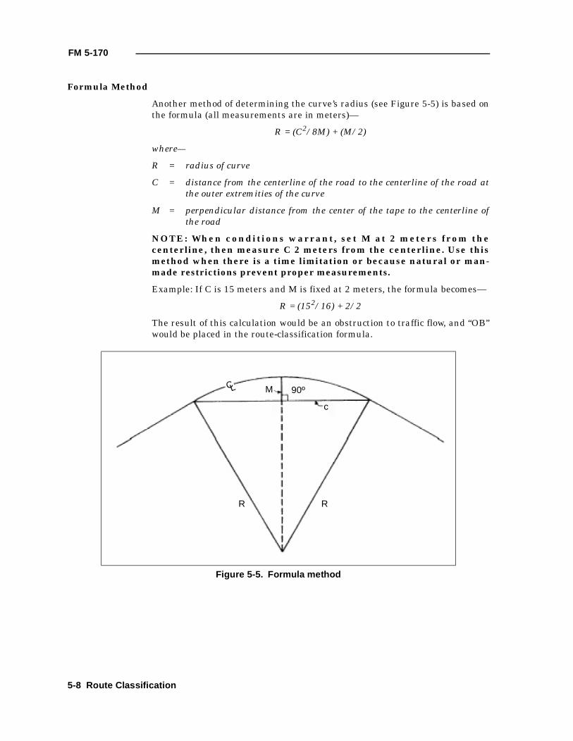
FM 5-170
Formula Method
Another method of determining the curve’s radius (see Figure 5-5) is based onthe formula (all measurements are in meters)—
R = (C2/8M) + (M/2)
where—
R = radius of curve
C = distance from the centerline of the road to the centerline of the road atthe outer extremities of the curve
M = perpendicular distance from the center of the tape to the centerline ofthe road
NOTE: When conditions warrant, set M at 2 meters from thecenterline, then measure C 2 meters from the centerline. Use thismethod when there is a time limitation or because natural or man-made restrictions prevent proper measurements.
Example: If C is 15 meters and M is fixed at 2 meters, the formula becomes—
R = (152/16) + 2/2
The result of this calculation would be an obstruction to traffic flow, and “OB”would be placed in the route-classification formula.
Figure 5-5. Formula method
C L M
c
R R
90º
5-8 Route Classification
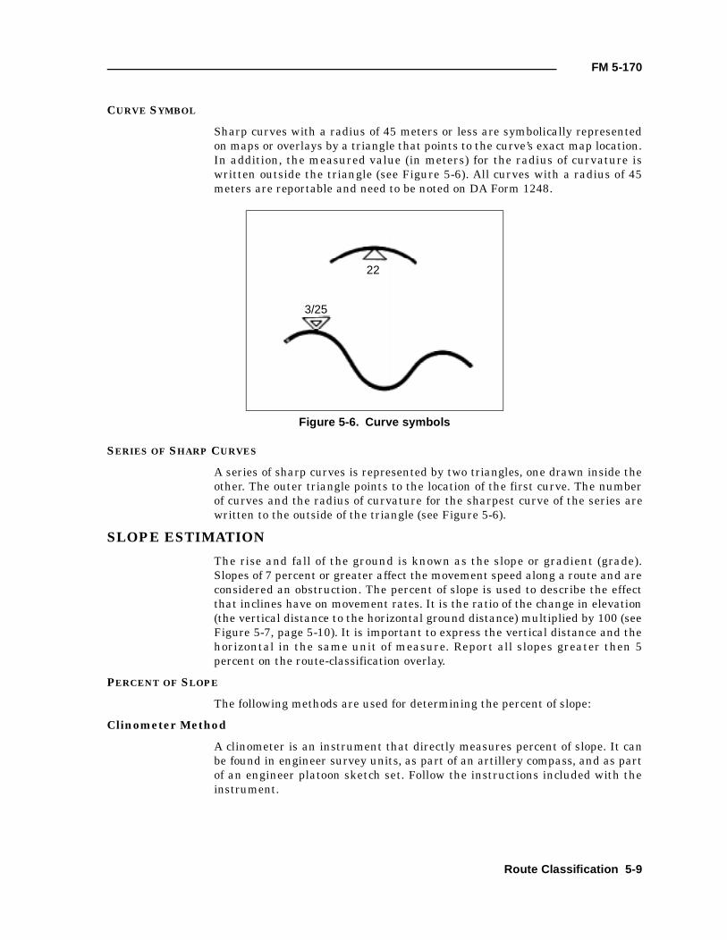
FM 5-170
CURVE SYMBOL
Sharp curves with a radius of 45 meters or less are symbolically representedon maps or overlays by a triangle that points to the curve’s exact map location.In addition, the measured value (in meters) for the radius of curvature iswritten outside the triangle (see Figure 5-6). All curves with a radius of 45meters are reportable and need to be noted on DA Form 1248.
SERIES OF SHARP CURVES
A series of sharp curves is represented by two triangles, one drawn inside theother. The outer triangle points to the location of the first curve. The numberof curves and the radius of curvature for the sharpest curve of the series arewritten to the outside of the triangle (see Figure 5-6).
SLOPE ESTIMATION
The rise and fall of the ground is known as the slope or gradient (grade).Slopes of 7 percent or greater affect the movement speed along a route and areconsidered an obstruction. The percent of slope is used to describe the effectthat inclines have on movement rates. It is the ratio of the change in elevation(the vertical distance to the horizontal ground distance) multiplied by 100 (seeFigure 5-7, page 5-10). It is important to express the vertical distance and thehorizontal in the same unit of measure. Report all slopes greater then 5percent on the route-classification overlay.
PERCENT OF SLOPE
The following methods are used for determining the percent of slope:
Clinometer Method
A clinometer is an instrument that directly measures percent of slope. It canbe found in engineer survey units, as part of an artillery compass, and as partof an engineer platoon sketch set. Follow the instructions included with theinstrument.
Figure 5-6. Curve symbols
22
3/25
Route Classification 5-9
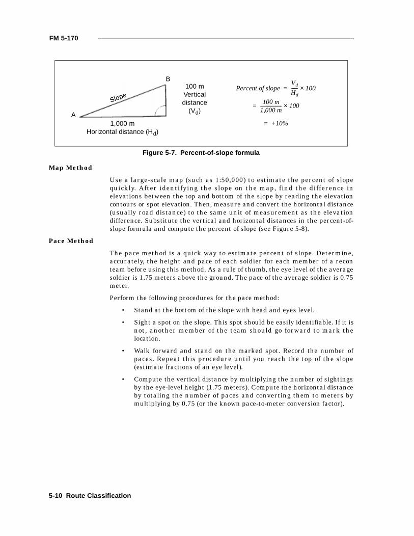
FM 5-170
Map Method
Use a large-scale map (such as 1:50,000) to estimate the percent of slopequickly. After identifying the slope on the map, find the difference inelevations between the top and bottom of the slope by reading the elevationcontours or spot elevation. Then, measure and convert the horizontal distance(usually road distance) to the same unit of measurement as the elevationdifference. Substitute the vertical and horizontal distances in the percent-of-slope formula and compute the percent of slope (see Figure 5-8).
Pace Method
The pace method is a quick way to estimate percent of slope. Determine,accurately, the height and pace of each soldier for each member of a reconteam before using this method. As a rule of thumb, the eye level of the averagesoldier is 1.75 meters above the ground. The pace of the average soldier is 0.75meter.
Perform the following procedures for the pace method:
• Stand at the bottom of the slope with head and eyes level.
• Sight a spot on the slope. This spot should be easily identifiable. If it isnot, another member of the team should go forward to mark thelocation.
• Walk forward and stand on the marked spot. Record the number ofpaces. Repeat this procedure until you reach the top of the slope(estimate fractions of an eye level).
• Compute the vertical distance by multiplying the number of sightingsby the eye-level height (1.75 meters). Compute the horizontal distanceby totaling the number of paces and converting them to meters bymultiplying by 0.75 (or the known pace-to-meter conversion factor).
Figure 5-7. Percent-of-slope formula
A
B
Slope
1,000 mHorizontal distance (Hd)
100 mVerticaldistance
(Vd)
Percent of slopeVd
Hd------ 100×
100 m1,000 m------------------- 100
+10%=
×=
=
5-10 Route Classification
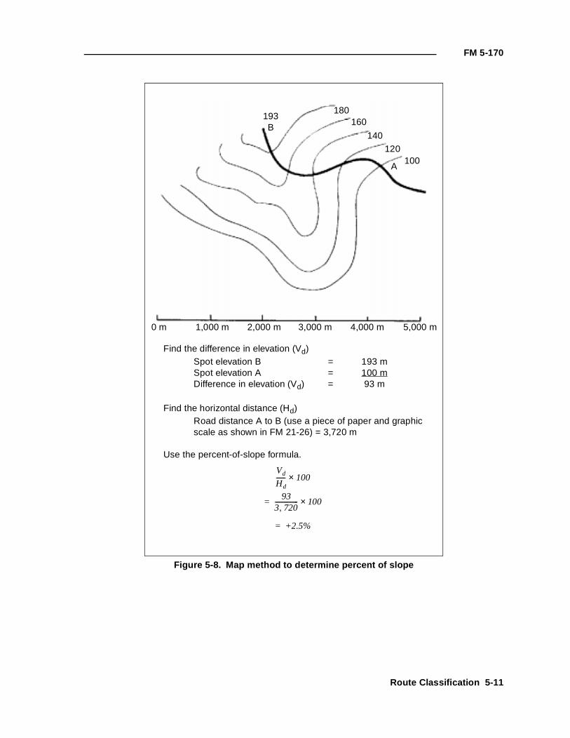
FM 5-170
Figure 5-8. Map method to determine percent of slope
193B
180160
140120
100A
0 m 1,000 m 2,000 m 3,000 m 4,000 m 5,000 m
Find the difference in elevation (Vd)Spot elevation B = 193 mSpot elevation A = 100 mDifference in elevation (Vd) = 93 m
Find the horizontal distance (Hd)Road distance A to B (use a piece of paper and graphicscale as shown in FM 21-26) = 3,720 m
Use the percent-of-slope formula.
Vd
Hd------ 100×
933 720,--------------- 100
+2.5%=
×=
Route Classification 5-11
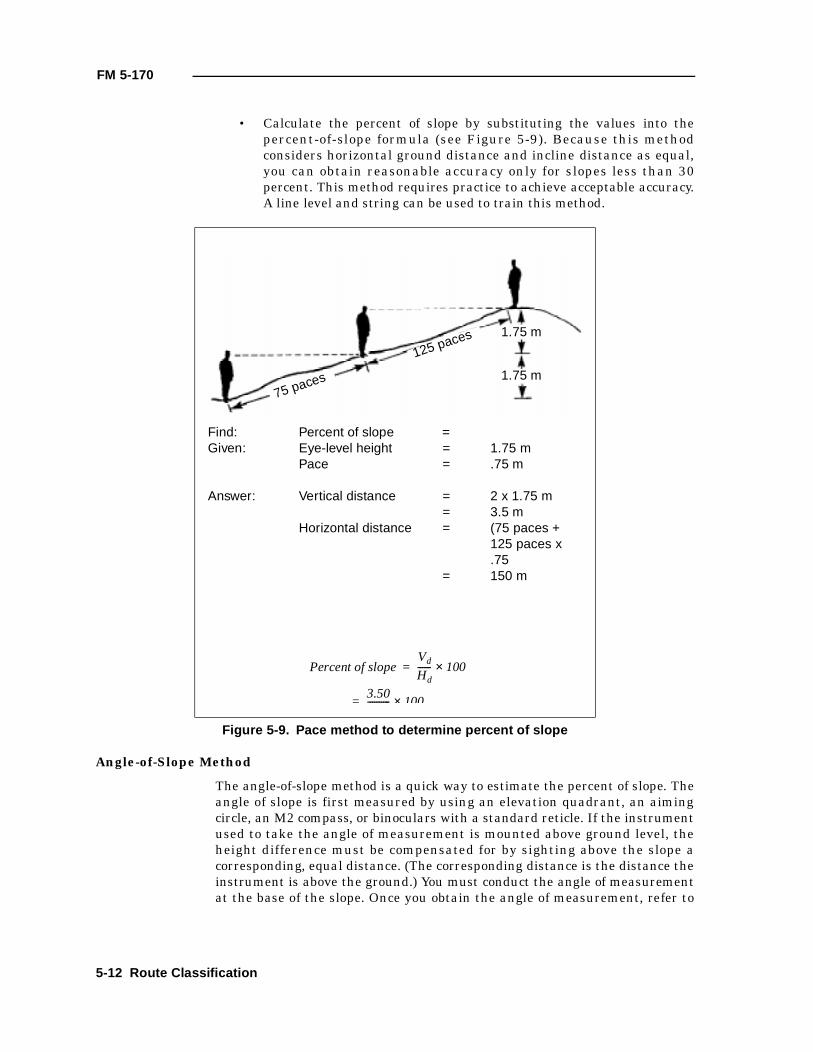
FM 5-170
• Calculate the percent of slope by substituting the values into thepercent-of-slope formula (see Figure 5-9). Because this methodconsiders horizontal ground distance and incline distance as equal,you can obtain reasonable accuracy only for slopes less than 30percent. This method requires practice to achieve acceptable accuracy.A line level and string can be used to train this method.
Angle-of-Slope Method
The angle-of-slope method is a quick way to estimate the percent of slope. Theangle of slope is first measured by using an elevation quadrant, an aimingcircle, an M2 compass, or binoculars with a standard reticle. If the instrumentused to take the angle of measurement is mounted above ground level, theheight difference must be compensated for by sighting above the slope acorresponding, equal distance. (The corresponding distance is the distance theinstrument is above the ground.) You must conduct the angle of measurementat the base of the slope. Once you obtain the angle of measurement, refer to
Figure 5-9. Pace method to determine percent of slope
75 paces
125 paces 1.75 m
1.75 m
Find: Percent of slope =Given: Eye-level height = 1.75 m
Pace = .75 m
Answer: Vertical distance = 2 x 1.75 m= 3.5 m
Horizontal distance = (75 paces +125 paces x.75
= 150 m
Percent of slopeVd
Hd------ 100
3.50---------- 100×=
×=
5-12 Route Classification
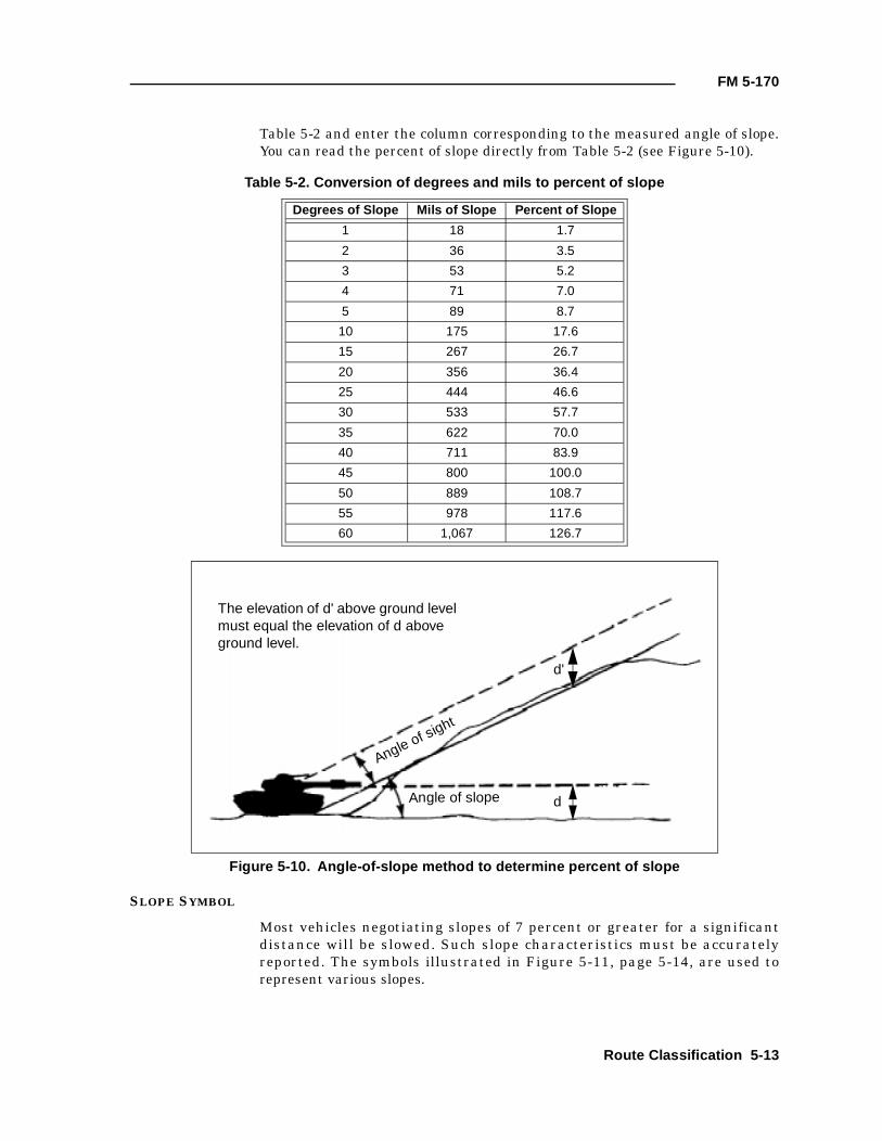
FM 5-170
Table 5-2 and enter the column corresponding to the measured angle of slope.You can read the percent of slope directly from Table 5-2 (see Figure 5-10).
SLOPE SYMBOL
Most vehicles negotiating slopes of 7 percent or greater for a significantdistance will be slowed. Such slope characteristics must be accuratelyreported. The symbols illustrated in Figure 5-11, page 5-14, are used torepresent various slopes.
Table 5-2. Conversion of degrees and mils to percent of slope
Degrees of Slope Mils of Slope Percent of Slope
1 18 1.7
2 36 3.5
3 53 5.2
4 71 7.0
5 89 8.7
10 175 17.6
15 267 26.7
20 356 36.4
25 444 46.6
30 533 57.7
35 622 70.0
40 711 83.9
45 800 100.0
50 889 108.7
55 978 117.6
60 1,067 126.7
Figure 5-10. Angle-of-slope method to determine percent of slope
The elevation of d' above ground level must equal the elevation of d above ground level.
Angle of sight
Angle of slope d
d'
Route Classification 5-13
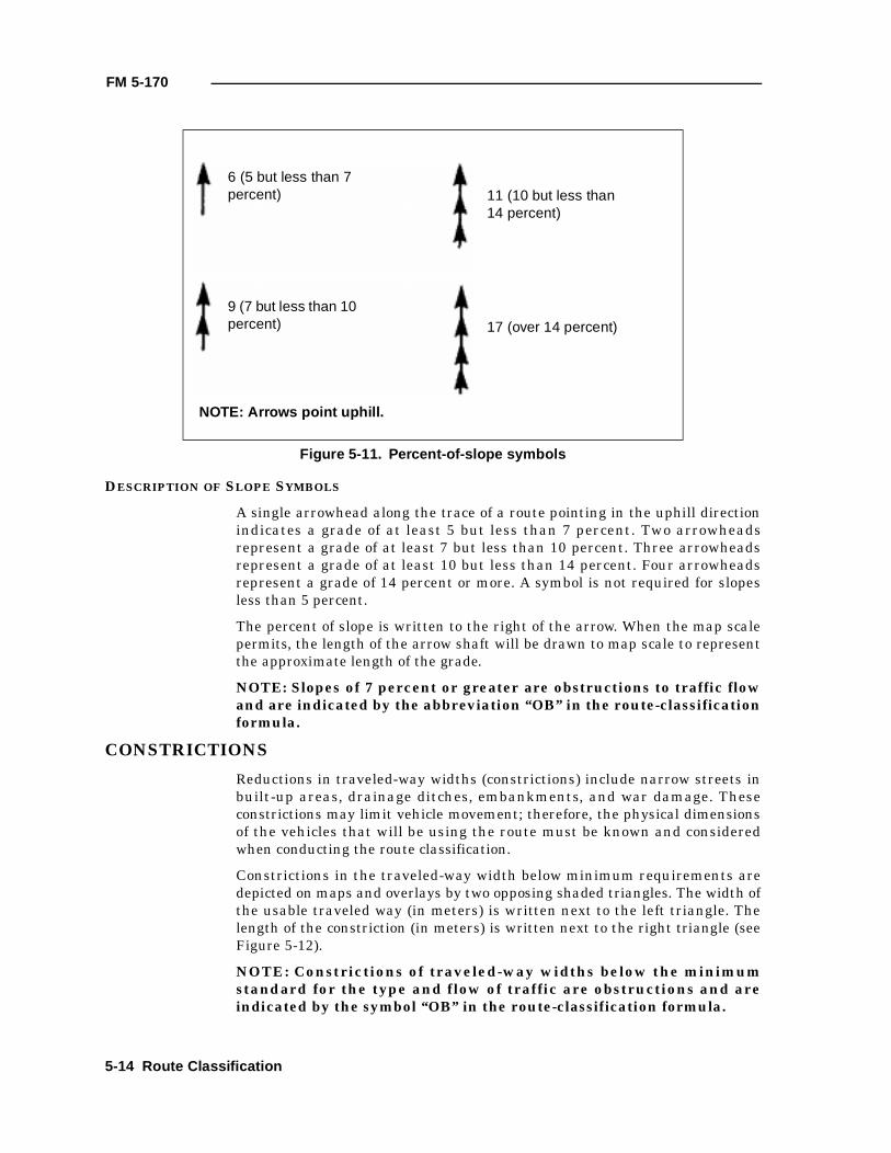
FM 5-170
DESCRIPTION OF SLOPE SYMBOLS
A single arrowhead along the trace of a route pointing in the uphill directionindicates a grade of at least 5 but less than 7 percent. Two arrowheadsrepresent a grade of at least 7 but less than 10 percent. Three arrowheadsrepresent a grade of at least 10 but less than 14 percent. Four arrowheadsrepresent a grade of 14 percent or more. A symbol is not required for slopesless than 5 percent.
The percent of slope is written to the right of the arrow. When the map scalepermits, the length of the arrow shaft will be drawn to map scale to representthe approximate length of the grade.
NOTE: Slopes of 7 percent or greater are obstructions to traffic flowand are indicated by the abbreviation “OB” in the route-classificationformula.
CONSTRICTIONS
Reductions in traveled-way widths (constrictions) include narrow streets inbuilt-up areas, drainage ditches, embankments, and war damage. Theseconstrictions may limit vehicle movement; therefore, the physical dimensionsof the vehicles that will be using the route must be known and consideredwhen conducting the route classification.
Constrictions in the traveled-way width below minimum requirements aredepicted on maps and overlays by two opposing shaded triangles. The width ofthe usable traveled way (in meters) is written next to the left triangle. Thelength of the constriction (in meters) is written next to the right triangle (seeFigure 5-12).
NOTE: Constrictions of traveled-way widths below the minimumstandard for the type and flow of traffic are obstructions and areindicated by the symbol “OB” in the route-classification formula.
Figure 5-11. Percent-of-slope symbols
6 (5 but less than 7 percent)
9 (7 but less than 10 percent)
11 (10 but less than 14 percent)
17 (over 14 percent)
NOTE: Arrows point uphill.
5-14 Route Classification
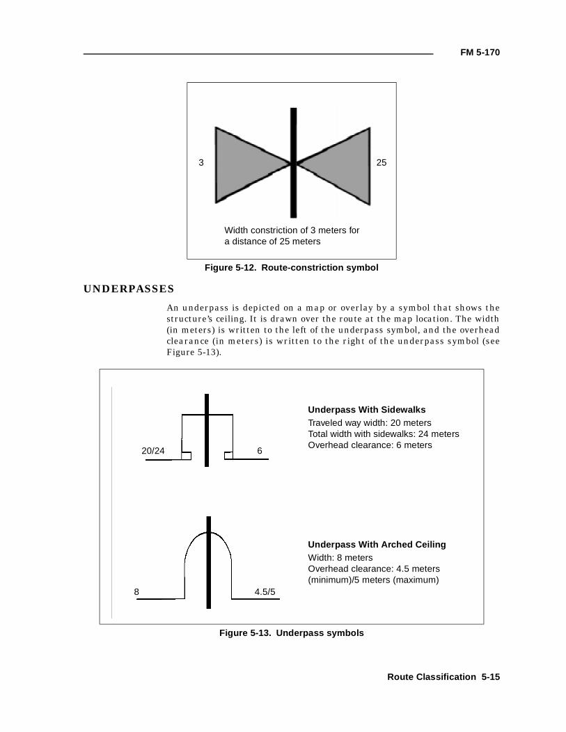
FM 5-170
UNDERPASSES
An underpass is depicted on a map or overlay by a symbol that shows thestructure’s ceiling. It is drawn over the route at the map location. The width(in meters) is written to the left of the underpass symbol, and the overheadclearance (in meters) is written to the right of the underpass symbol (seeFigure 5-13).
Figure 5-12. Route-constriction symbol
Figure 5-13. Underpass symbols
3 25
Width constriction of 3 meters for a distance of 25 meters
20/24 6
4.5/58
Underpass With SidewalksTraveled way width: 20 metersTotal width with sidewalks: 24 metersOverhead clearance: 6 meters
Underpass With Arched CeilingWidth: 8 metersOverhead clearance: 4.5 meters (minimum)/5 meters (maximum)
Route Classification 5-15
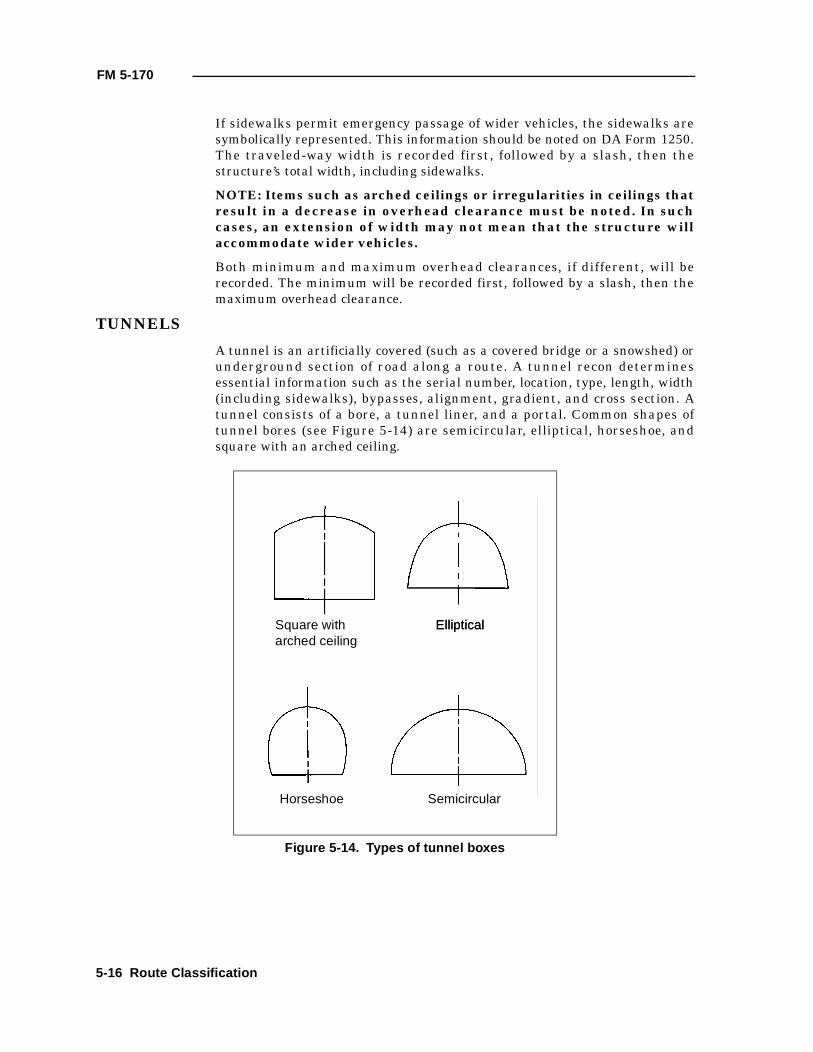
FM 5-170
If sidewalks permit emergency passage of wider vehicles, the sidewalks aresymbolically represented. This information should be noted on DA Form 1250.The traveled-way width is recorded first, followed by a slash, then thestructure’s total width, including sidewalks.
NOTE: Items such as arched ceilings or irregularities in ceilings thatresult in a decrease in overhead clearance must be noted. In suchcases, an extension of width may not mean that the structure willaccommodate wider vehicles.
Both minimum and maximum overhead clearances, if different, will berecorded. The minimum will be recorded first, followed by a slash, then themaximum overhead clearance.
TUNNELS
A tunnel is an artificially covered (such as a covered bridge or a snowshed) orunderground section of road along a route. A tunnel recon determinesessential information such as the serial number, location, type, length, width(including sidewalks), bypasses, alignment, gradient, and cross section. Atunnel consists of a bore, a tunnel liner, and a portal. Common shapes oftunnel bores (see Figure 5-14) are semicircular, elliptical, horseshoe, andsquare with an arched ceiling.
Figure 5-14. Types of tunnel boxes
Square witharched ceiling
EllipticalElliptical
Horseshoe Semicircular
5-16 Route Classification
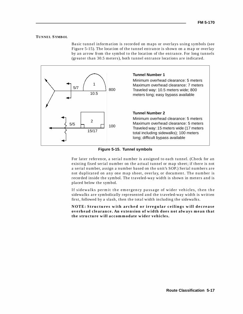
FM 5-170
TUNNEL SYMBOL
Basic tunnel information is recorded on maps or overlays using symbols (seeFigure 5-15). The location of the tunnel entrance is shown on a map or overlayby an arrow from the symbol to the location of the entrance. For long tunnels(greater than 30.5 meters), both tunnel entrance locations are indicated.
For later reference, a serial number is assigned to each tunnel. (Check for anexisting fixed serial number on the actual tunnel or map sheet; if there is nota serial number, assign a number based on the unit’s SOP.) Serial numbers arenot duplicated on any one map sheet, overlay, or document. The number isrecorded inside the symbol. The traveled-way width is shown in meters and isplaced below the symbol.
If sidewalks permit the emergency passage of wider vehicles, then thesidewalks are symbolically represented and the traveled-way width is writtenfirst, followed by a slash, then the total width including the sidewalks.
NOTE: Structures with arched or irregular ceilings will decreaseoverhead clearance. An extension of width does not always mean thatthe structure will accommodate wider vehicles.
Figure 5-15. Tunnel symbols
5/71
10.5800
Tunnel Number 1Minimum overhead clearance: 5 meters Maximum overhead clearance: 7 metersTraveled way: 10.5 meters wide; 800 meters long; easy bypass available
Tunnel Number 2Minimum overhead clearance: 5 meters Maximum overhead clearance: 5 metersTraveled way: 15 meters wide (17 meters total including sidewalks); 100 meters long; difficult bypass available
5/52
15/17100
Route Classification 5-17
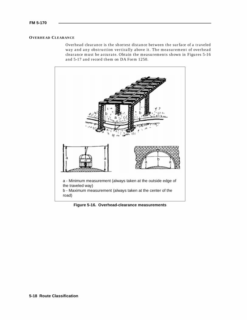
FM 5-170
OVERHEAD CLEARANCE
Overhead clearance is the shortest distance between the surface of a traveledway and any obstruction vertically above it. The measurement of overheadclearance must be accurate. Obtain the measurements shown in Figures 5-16and 5-17 and record them on DA Form 1250.
Figure 5-16. Overhead-clearance measurements
b b
bb
a
a aa a
a - Minimum measurement (always taken at the outside edge of the traveled way)b - Maximum measurement (always taken at the center of the road)
5-18 Route Classification

FM 5-170
Figure 5-17. Dimensions required for tunnels
1a
5
1
6
6a 6a
44a
3
2
1 - Portal-to-portal length of tunnel1a - Centerline distance of tunnel2 - Effective width of the traveled way, curb to curb3 - Horizontal clearance (minimum width of the tunnel bore measured at least 4 feet above the traveled way4 - Overhead clearance (minimum distance between the top of the traveled way and the lower edge of the tunnel ceiling or any obstruction below the
ceiling, such as trolley wires or electric light wires)4a - Rise of tunnel arch (radius of curved portion)5 - Radius of curvature of the traveled way, either measured or estimated6 - Gradient (percentage of rise of the traveled way between portals)6a - Change in gradient within the tunnel (percentage of rise each way from break of grade)
Plan
Profile
Route Classification 5-19
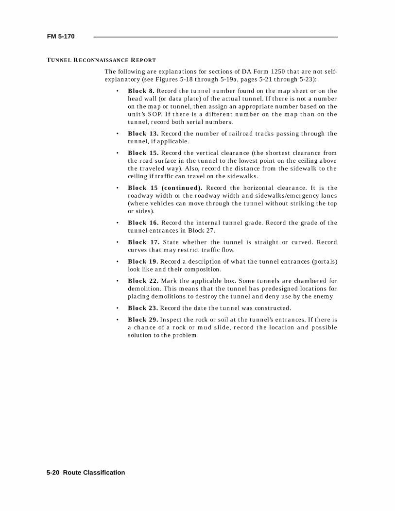
FM 5-170
TUNNEL RECONNAISSANCE REPORT
The following are explanations for sections of DA Form 1250 that are not self-explanatory (see Figures 5-18 through 5-19a, pages 5-21 through 5-23):
• Block 8. Record the tunnel number found on the map sheet or on thehead wall (or data plate) of the actual tunnel. If there is not a numberon the map or tunnel, then assign an appropriate number based on theunit’s SOP. If there is a different number on the map than on thetunnel, record both serial numbers.
• Block 13. Record the number of railroad tracks passing through thetunnel, if applicable.
• Block 15. Record the vertical clearance (the shortest clearance fromthe road surface in the tunnel to the lowest point on the ceiling abovethe traveled way). Also, record the distance from the sidewalk to theceiling if traffic can travel on the sidewalks.
• Block 15 (continued). Record the horizontal clearance. It is theroadway width or the roadway width and sidewalks/emergency lanes(where vehicles can move through the tunnel without striking the topor sides).
• Block 16. Record the internal tunnel grade. Record the grade of thetunnel entrances in Block 27.
• Block 17. State whether the tunnel is straight or curved. Recordcurves that may restrict traffic flow.
• Block 19. Record a description of what the tunnel entrances (portals)look like and their composition.
• Block 22. Mark the applicable box. Some tunnels are chambered fordemolition. This means that the tunnel has predesigned locations forplacing demolitions to destroy the tunnel and deny use by the enemy.
• Block 23. Record the date the tunnel was constructed.
• Block 29. Inspect the rock or soil at the tunnel’s entrances. If there isa chance of a rock or mud slide, record the location and possiblesolution to the problem.
5-20 Route Classification
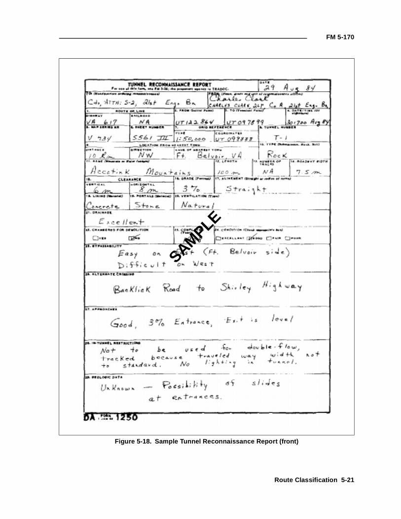
FM 5-170
Figure 5-18. Sample Tunnel Reconnaissance Report (front)
SAMPLE
Route Classification 5-21
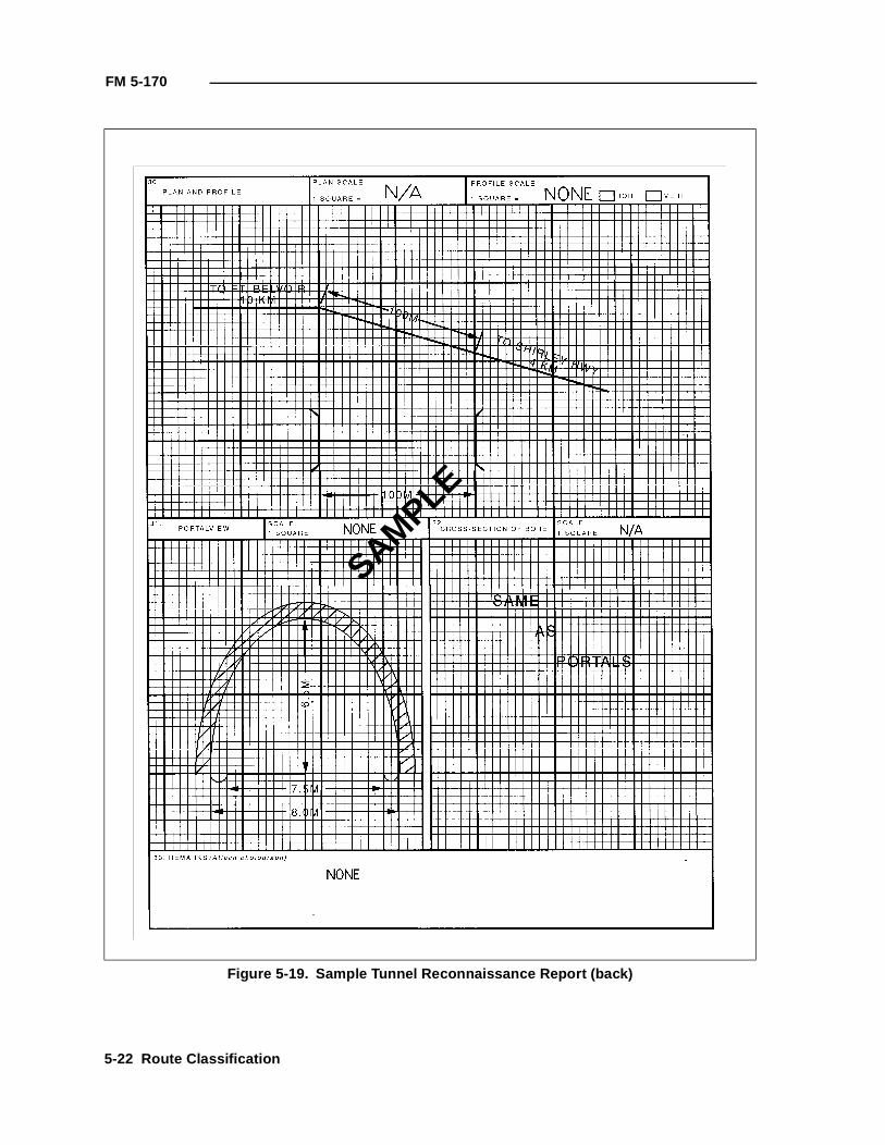
FM 5-170
Figure 5-19. Sample Tunnel Reconnaissance Report (back)
SAMPLE
5-22 Route Classification
FM 5-170
Figure 5-19a. Portal view of tunnel
Mountain earth
Brick
River rock
North entrance
Route Classification 5-23
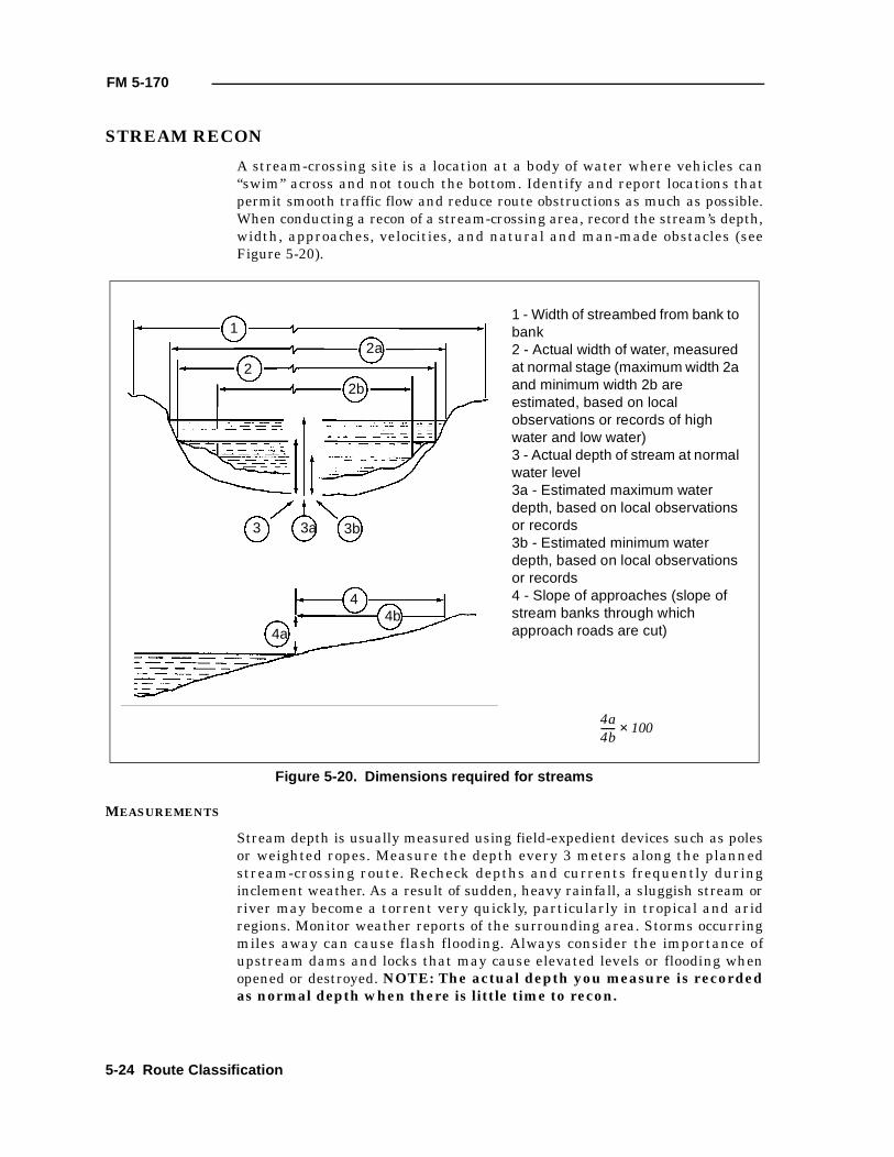
FM 5-170
STREAM RECON
A stream-crossing site is a location at a body of water where vehicles can“swim” across and not touch the bottom. Identify and report locations thatpermit smooth traffic flow and reduce route obstructions as much as possible.When conducting a recon of a stream-crossing area, record the stream’s depth,width, approaches, velocities, and natural and man-made obstacles (seeFigure 5-20).
MEASUREMENTS
Stream depth is usually measured using field-expedient devices such as polesor weighted ropes. Measure the depth every 3 meters along the plannedstream-crossing route. Recheck depths and currents frequently duringinclement weather. As a result of sudden, heavy rainfall, a sluggish stream orriver may become a torrent very quickly, particularly in tropical and aridregions. Monitor weather reports of the surrounding area. Storms occurringmiles away can cause flash flooding. Always consider the importance ofupstream dams and locks that may cause elevated levels or flooding whenopened or destroyed. NOTE: The actual depth you measure is recordedas normal depth when there is little time to recon.
Figure 5-20. Dimensions required for streams
12a
22b
3 3a 3b
4
4a4b
1 - Width of streambed from bank to bank2 - Actual width of water, measured at normal stage (maximum width 2a and minimum width 2b are estimated, based on local observations or records of high water and low water)3 - Actual depth of stream at normal water level3a - Estimated maximum water depth, based on local observations or records3b - Estimated minimum water depth, based on local observations or records4 - Slope of approaches (slope of stream banks through which approach roads are cut)
4a4b------ 100×
5-24 Route Classification
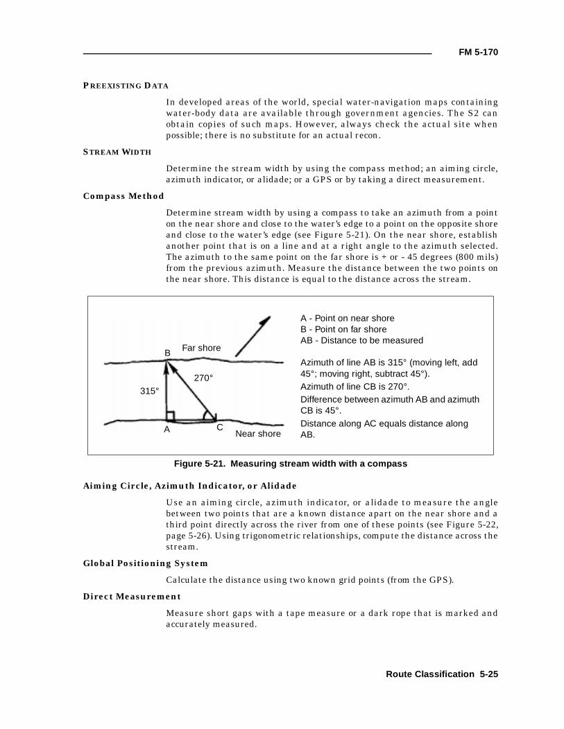
FM 5-170
PREEXISTING DATA
In developed areas of the world, special water-navigation maps containingwater-body data are available through government agencies. The S2 canobtain copies of such maps. However, always check the actual site whenpossible; there is no substitute for an actual recon.
STREAM WIDTH
Determine the stream width by using the compass method; an aiming circle,azimuth indicator, or alidade; or a GPS or by taking a direct measurement.
Compass Method
Determine stream width by using a compass to take an azimuth from a pointon the near shore and close to the water’s edge to a point on the opposite shoreand close to the water’s edge (see Figure 5-21). On the near shore, establishanother point that is on a line and at a right angle to the azimuth selected.The azimuth to the same point on the far shore is + or - 45 degrees (800 mils)from the previous azimuth. Measure the distance between the two points onthe near shore. This distance is equal to the distance across the stream.
Aiming Circle, Azimuth Indicator, or Alidade
Use an aiming circle, azimuth indicator, or alidade to measure the anglebetween two points that are a known distance apart on the near shore and athird point directly across the river from one of these points (see Figure 5-22,page 5-26). Using trigonometric relationships, compute the distance across thestream.
Global Positioning System
Calculate the distance using two known grid points (from the GPS).
Direct Measurement
Measure short gaps with a tape measure or a dark rope that is marked andaccurately measured.
Figure 5-21. Measuring stream width with a compass
Far shore
Near shore
315°270°
B
A C
A - Point on near shoreB - Point on far shoreAB - Distance to be measured
Azimuth of line AB is 315° (moving left, add 45°; moving right, subtract 45°).Azimuth of line CB is 270°.Difference between azimuth AB and azimuth CB is 45°.Distance along AC equals distance along AB.
Route Classification 5-25
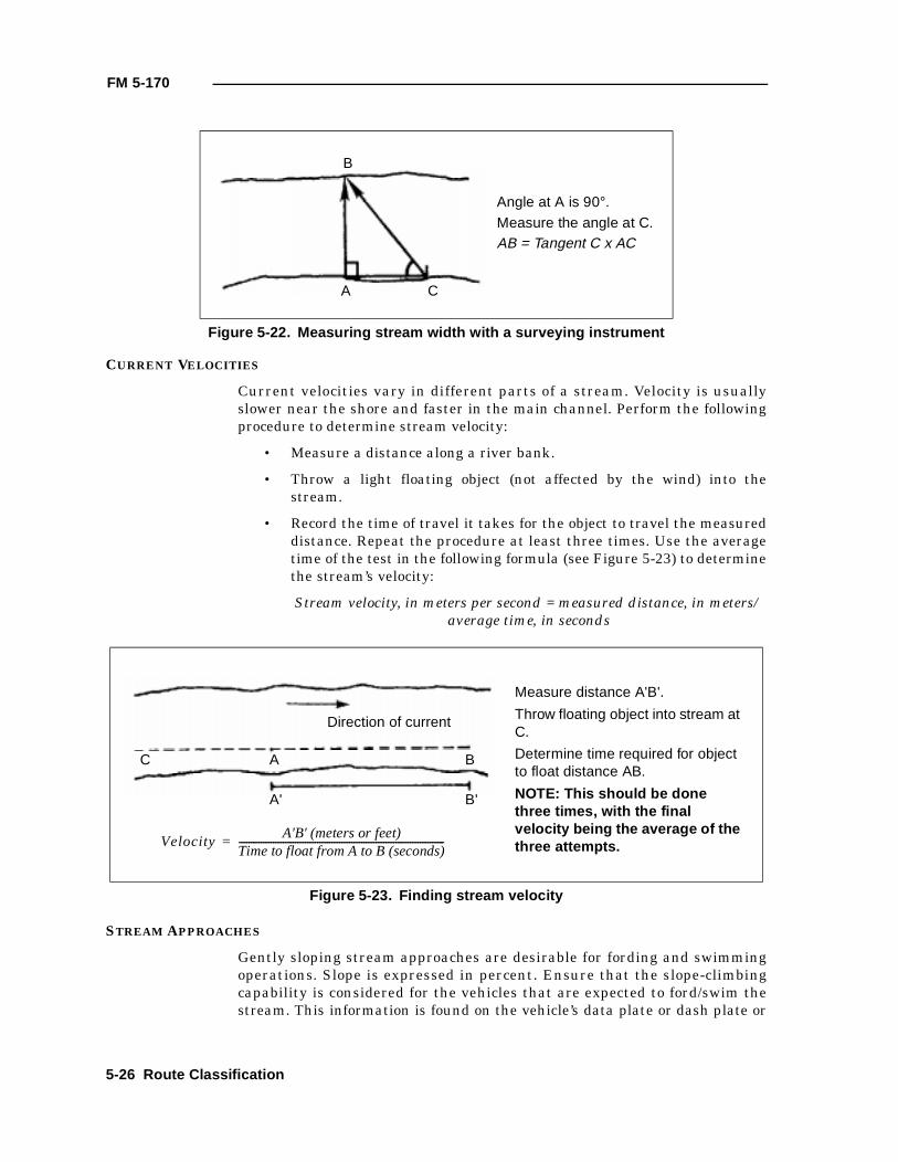
FM 5-170
CURRENT VELOCITIES
Current velocities vary in different parts of a stream. Velocity is usuallyslower near the shore and faster in the main channel. Perform the followingprocedure to determine stream velocity:
• Measure a distance along a river bank.
• Throw a light floating object (not affected by the wind) into thestream.
• Record the time of travel it takes for the object to travel the measureddistance. Repeat the procedure at least three times. Use the averagetime of the test in the following formula (see Figure 5-23) to determinethe stream’s velocity:
Stream velocity, in meters per second = measured distance, in meters/ average time, in seconds
STREAM APPROACHES
Gently sloping stream approaches are desirable for fording and swimmingoperations. Slope is expressed in percent. Ensure that the slope-climbingcapability is considered for the vehicles that are expected to ford/swim thestream. This information is found on the vehicle’s data plate or dash plate or
Figure 5-22. Measuring stream width with a surveying instrument
Figure 5-23. Finding stream velocity
B
A C
Angle at A is 90°.Measure the angle at C.AB = Tangent C x AC
Direction of current
C A B
A' B'
Measure distance A'B'.
Throw floating object into stream at C.
Determine time required for object to float distance AB.
NOTE: This should be done three times, with the final velocity being the average of the three attempts.Velocity
A'B' (meters or feet)Time to float from A to B (seconds)------------------------------------------------------------------------------------=
5-26 Route Classification
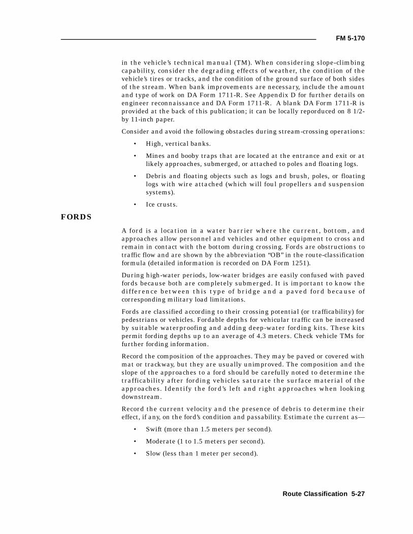
FM 5-170
in the vehicle’s technical manual (TM). When considering slope-climbingcapability, consider the degrading effects of weather, the condition of thevehicle’s tires or tracks, and the condition of the ground surface of both sidesof the stream. When bank improvements are necessary, include the amountand type of work on DA Form 1711-R. See Appendix D for further details onengineer reconnaissance and DA Form 1711-R. A blank DA Form 1711-R isprovided at the back of this publication; it can be locally reporduced on 8 1/2-by 11-inch paper.
Consider and avoid the following obstacles during stream-crossing operations:
• High, vertical banks.
• Mines and booby traps that are located at the entrance and exit or atlikely approaches, submerged, or attached to poles and floating logs.
• Debris and floating objects such as logs and brush, poles, or floatinglogs with wire attached (which will foul propellers and suspensionsystems).
• Ice crusts.
FORDS
A ford is a location in a water barrier where the current, bottom, andapproaches allow personnel and vehicles and other equipment to cross andremain in contact with the bottom during crossing. Fords are obstructions totraffic flow and are shown by the abbreviation “OB” in the route-classificationformula (detailed information is recorded on DA Form 1251).
During high-water periods, low-water bridges are easily confused with pavedfords because both are completely submerged. It is important to know thedifference between this type of bridge and a paved ford because ofcorresponding military load limitations.
Fords are classified according to their crossing potential (or trafficability) forpedestrians or vehicles. Fordable depths for vehicular traffic can be increasedby suitable waterproofing and adding deep-water fording kits. These kitspermit fording depths up to an average of 4.3 meters. Check vehicle TMs forfurther fording information.
Record the composition of the approaches. They may be paved or covered withmat or trackway, but they are usually unimproved. The composition and theslope of the approaches to a ford should be carefully noted to determine thetrafficability after fording vehicles saturate the surface material of theapproaches. Identify the ford’s left and right approaches when lookingdownstream.
Record the current velocity and the presence of debris to determine theireffect, if any, on the ford’s condition and passability. Estimate the current as—
• Swift (more than 1.5 meters per second).
• Moderate (1 to 1.5 meters per second).
• Slow (less than 1 meter per second).
Route Classification 5-27
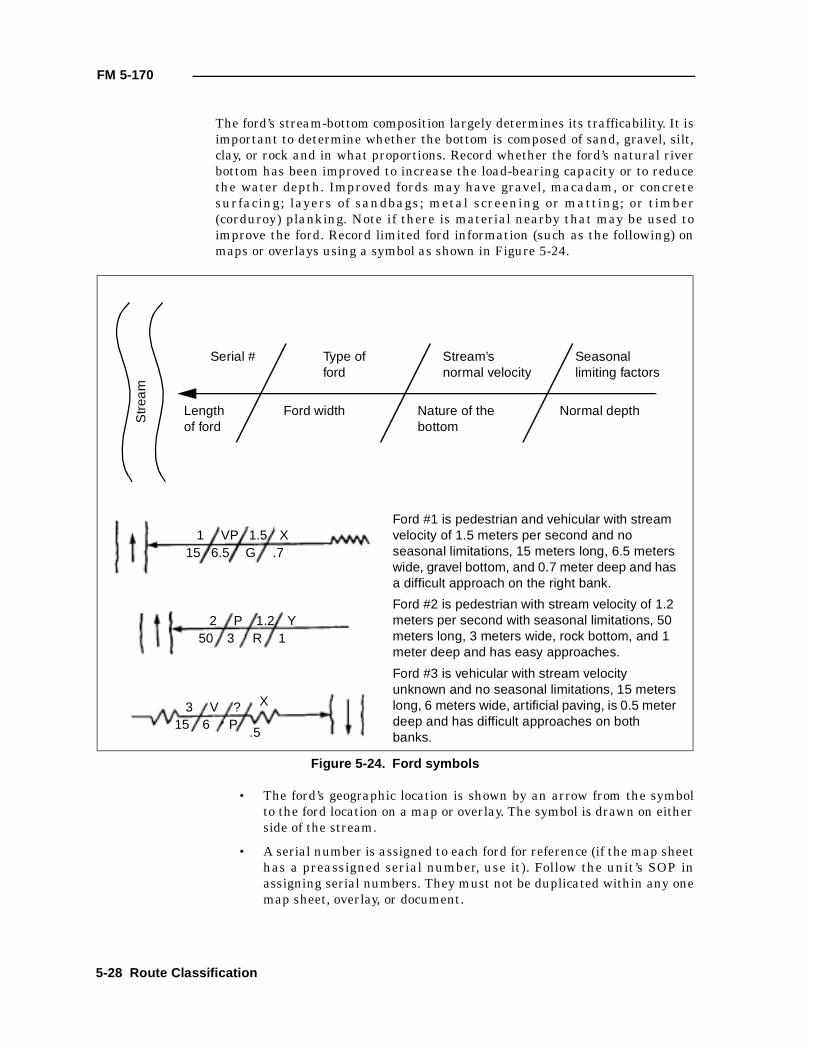
FM 5-170
The ford’s stream-bottom composition largely determines its trafficability. It isimportant to determine whether the bottom is composed of sand, gravel, silt,clay, or rock and in what proportions. Record whether the ford’s natural riverbottom has been improved to increase the load-bearing capacity or to reducethe water depth. Improved fords may have gravel, macadam, or concretesurfacing; layers of sandbags; metal screening or matting; or timber(corduroy) planking. Note if there is material nearby that may be used toimprove the ford. Record limited ford information (such as the following) onmaps or overlays using a symbol as shown in Figure 5-24.
• The ford’s geographic location is shown by an arrow from the symbolto the ford location on a map or overlay. The symbol is drawn on eitherside of the stream.
• A serial number is assigned to each ford for reference (if the map sheethas a preassigned serial number, use it). Follow the unit’s SOP inassigning serial numbers. They must not be duplicated within any onemap sheet, overlay, or document.
Figure 5-24. Ford symbols
1 VP 1.5 X15 6.5 G .7
2 P 1.2 Y50 3 R 1
3 V ? X
15 6 P.5
Ford #1 is pedestrian and vehicular with stream velocity of 1.5 meters per second and no seasonal limitations, 15 meters long, 6.5 meters wide, gravel bottom, and 0.7 meter deep and has a difficult approach on the right bank.
Ford #2 is pedestrian with stream velocity of 1.2 meters per second with seasonal limitations, 50 meters long, 3 meters wide, rock bottom, and 1 meter deep and has easy approaches.
Ford #3 is vehicular with stream velocity unknown and no seasonal limitations, 15 meters long, 6 meters wide, artificial paving, is 0.5 meter deep and has difficult approaches on both banks.
Serial # Type of ford
Stream’s normal velocity
Seasonal limiting factors
Length of ford
Ford width Nature of the bottom
Normal depth
Str
eam
5-28 Route Classification
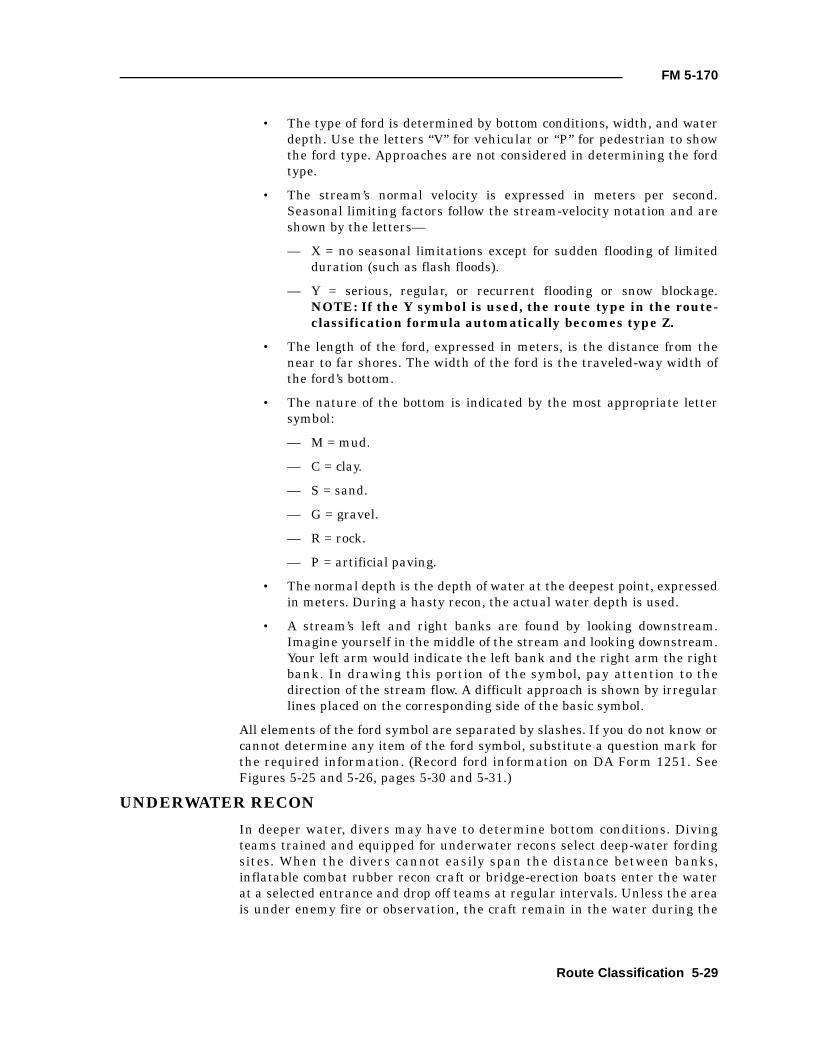
FM 5-170
• The type of ford is determined by bottom conditions, width, and waterdepth. Use the letters “V” for vehicular or “P” for pedestrian to showthe ford type. Approaches are not considered in determining the fordtype.
• The stream’s normal velocity is expressed in meters per second.Seasonal limiting factors follow the stream-velocity notation and areshown by the letters—
— X = no seasonal limitations except for sudden flooding of limitedduration (such as flash floods).
— Y = serious, regular, or recurrent flooding or snow blockage.NOTE: If the Y symbol is used, the route type in the route-classification formula automatically becomes type Z.
• The length of the ford, expressed in meters, is the distance from thenear to far shores. The width of the ford is the traveled-way width ofthe ford’s bottom.
• The nature of the bottom is indicated by the most appropriate lettersymbol:
— M = mud.
— C = clay.
— S = sand.
— G = gravel.
— R = rock.
— P = artificial paving.
• The normal depth is the depth of water at the deepest point, expressedin meters. During a hasty recon, the actual water depth is used.
• A stream’s left and right banks are found by looking downstream.Imagine yourself in the middle of the stream and looking downstream.Your left arm would indicate the left bank and the right arm the rightbank. In drawing this portion of the symbol, pay attention to thedirection of the stream flow. A difficult approach is shown by irregularlines placed on the corresponding side of the basic symbol.
All elements of the ford symbol are separated by slashes. If you do not know orcannot determine any item of the ford symbol, substitute a question mark forthe required information. (Record ford information on DA Form 1251. SeeFigures 5-25 and 5-26, pages 5-30 and 5-31.)
UNDERWATER RECON
In deeper water, divers may have to determine bottom conditions. Divingteams trained and equipped for underwater recons select deep-water fordingsites. When the divers cannot easily span the distance between banks,inflatable combat rubber recon craft or bridge-erection boats enter the waterat a selected entrance and drop off teams at regular intervals. Unless the areais under enemy fire or observation, the craft remain in the water during the
Route Classification 5-29
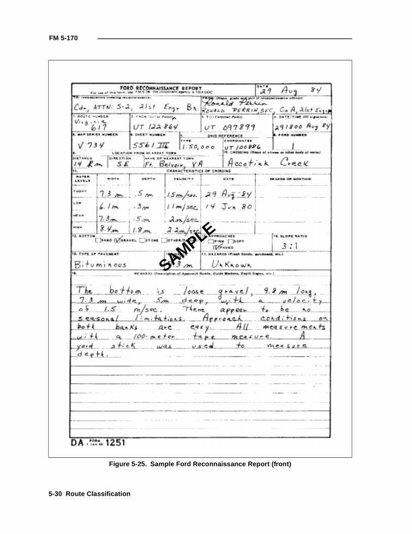
FM 5-170
Figure 5-25. Sample Ford Reconnaissance Report (front)
SAMPLE
5-30 Route Classification
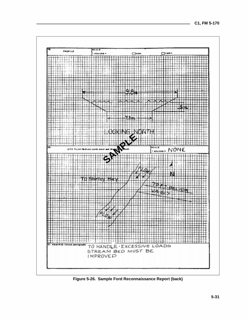
C1, FM 5-170
Figure 5-26. Sample Ford Reconnaissance Report (back)
SAMPLE
5-31
C1, FM 5-170
recon and pick up divers when the operation is completed. Helicopters may beused to drop teams in the water or place teams on the far shore if the situationpermits. Engineer light diving teams routinely conduct river recons at night.
To assist underwater recon teams in maintaining direction, weighted lines(transverse lines) may be placed across the bottom of the water obstacle.Buoys or other floating objects are attached to the lines to indicate the surveyarea for the underwater recon team(s). When the current is greater than 1.3meters per second, underwater recon personnel will have difficultymaintaining a position along the line selected. To assist divers, anothertransverse line, parallel to the original line and with lateral lines connectingboth lines, may be placed upstream.
Bottom conditions are easily determined during periods of good visibility andwhen the water is clear. However, under blackout conditions or when thewater is murky, the recon is much slower because swimmers must feel theirway across. If the tactical situation permits, diver’s may use underwaterlanterns.
Environmental conditions (such as depth, bottom type, tides and currents,visibility, and temperature) have an effect on divers, diving techniques, andequipment. The length of time that divers can remain underwater depends onwater depth, time at depth, and equipment used. When conducting a recon ina current, swimmers expend more energy, tire more easily, and use their airsupply more quickly. In water temperatures between 73° and 85°F, divers canwork comfortably in their swimsuits, but will chill in one to two hours if notexercising. In water temperatures above 85°F, the divers overheat. Themaximum water temperature that can be endured, even at rest, is 96°F. Attemperatures below 73°F, unprotected divers will be affected by excessive heatloss and become chilled within a short period of time. In cold water, the senseof touch and the ability to work with the hands are affected. Air tanks vary insize and govern how long divers can operate. Extra tanks should be availablefor underwater recon teams, and the facilities to recharge equipment shouldbe located close enough to respond to team requirements.
Units complete a river-recon report to transmit important information aboutthe river’s location, near- and far-shore characteristics, and rivercharacteristics. The information is recorded on DA Form 7398-R as shown inFigures 5-27 and 5-28, pages 5-33 and 5-34.
FERRY RECON
Ferries are considered obstructions to traffic flow and are indicated by theabbreviation “OB” in the route-classification formula. Ferryboat constructionvaries widely and ranges from expedient rafts to ocean-going vessels. Ferriesdiffer in physical appearance and capacity depending upon the water’s width,depth, and current and the characteristics of the traffic to be moved. Ferriesmay be propelled by oars; cable and pulleys; poles; the stream current; orsteam, gasoline, or diesel engines.
CIVIL FERRIES AND FERRY SITES
Usually, the capacity of a civil ferryboat is expressed in tons and total numberof passengers. In addition, it is often assigned an MLC number. Ensure that
5-32
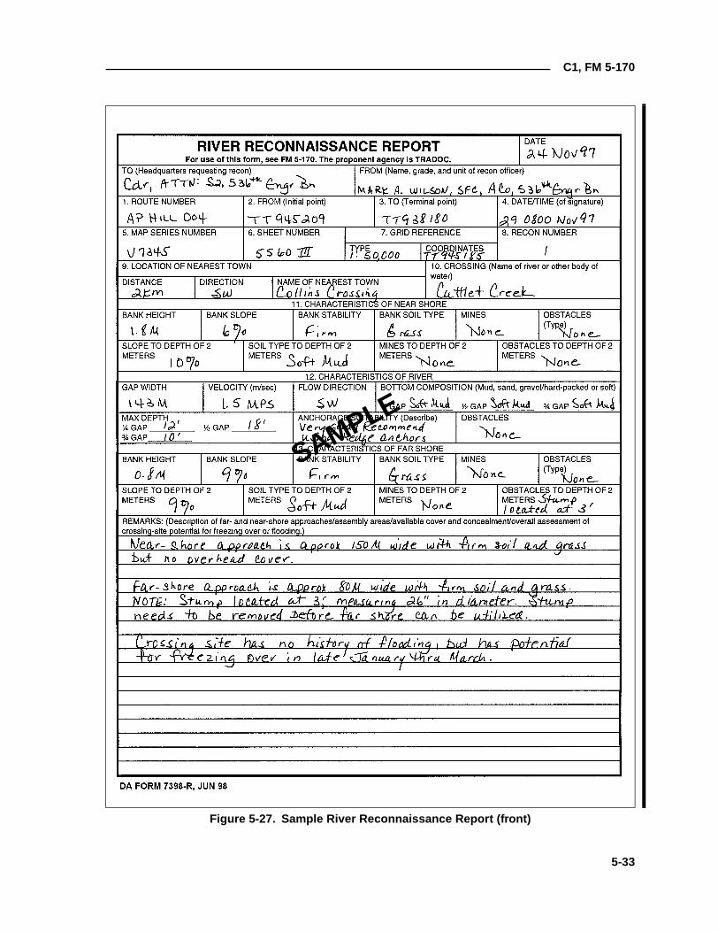
C1, FM 5-170
Figure 5-27. Sample River Reconnaissance Report (front)
SAMPLE
5-33
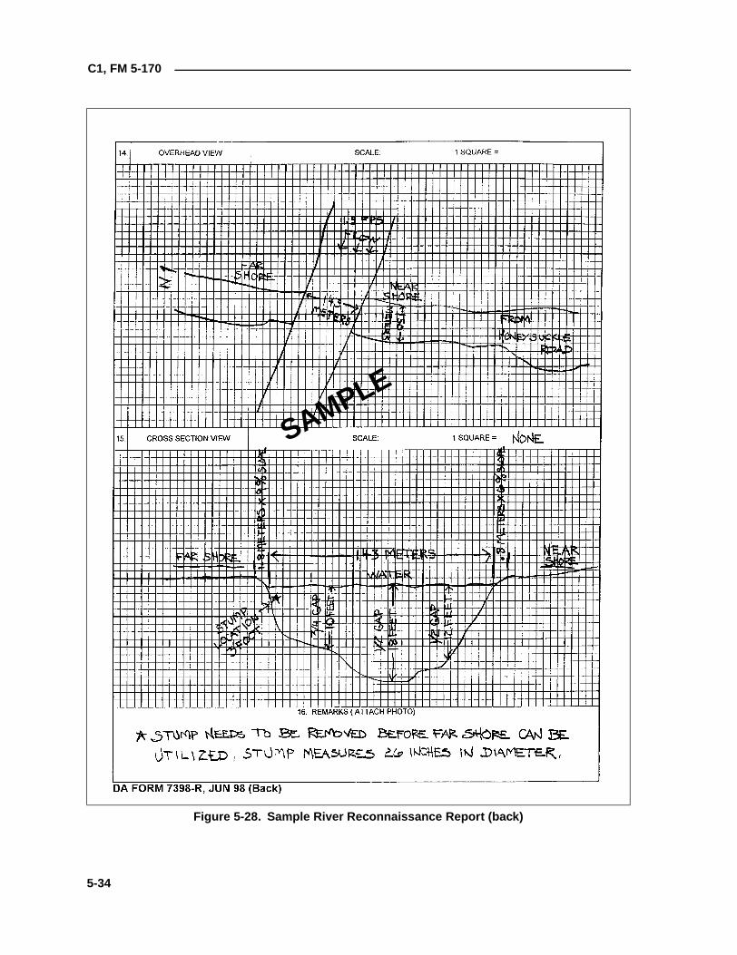
C1, FM 5-170
Figure 5-28. Sample River Reconnaissance Report (back)
SAMPLE
5-34
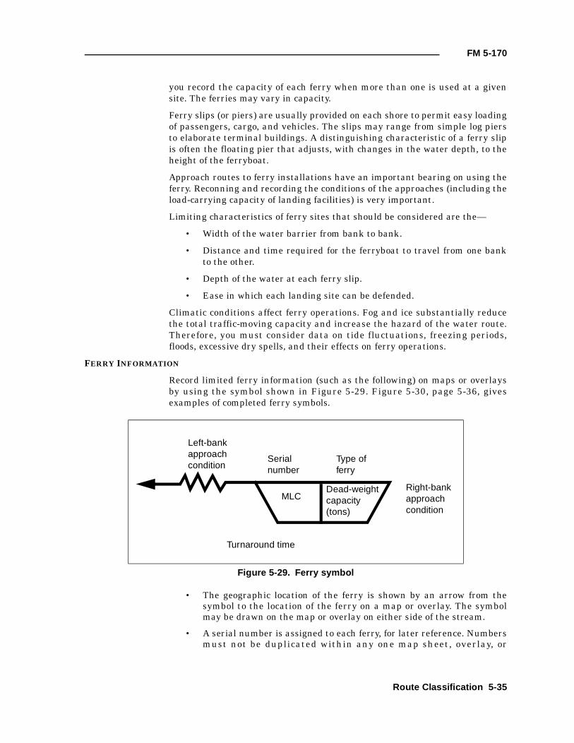
FM 5-170
you record the capacity of each ferry when more than one is used at a givensite. The ferries may vary in capacity.
Ferry slips (or piers) are usually provided on each shore to permit easy loadingof passengers, cargo, and vehicles. The slips may range from simple log piersto elaborate terminal buildings. A distinguishing characteristic of a ferry slipis often the floating pier that adjusts, with changes in the water depth, to theheight of the ferryboat.
Approach routes to ferry installations have an important bearing on using theferry. Reconning and recording the conditions of the approaches (including theload-carrying capacity of landing facilities) is very important.
Limiting characteristics of ferry sites that should be considered are the—
• Width of the water barrier from bank to bank.
• Distance and time required for the ferryboat to travel from one bankto the other.
• Depth of the water at each ferry slip.
• Ease in which each landing site can be defended.
Climatic conditions affect ferry operations. Fog and ice substantially reducethe total traffic-moving capacity and increase the hazard of the water route.Therefore, you must consider data on tide fluctuations, freezing periods,floods, excessive dry spells, and their effects on ferry operations.
FERRY INFORMATION
Record limited ferry information (such as the following) on maps or overlaysby using the symbol shown in Figure 5-29. Figure 5-30, page 5-36, givesexamples of completed ferry symbols.
• The geographic location of the ferry is shown by an arrow from thesymbol to the location of the ferry on a map or overlay. The symbolmay be drawn on the map or overlay on either side of the stream.
• A serial number is assigned to each ferry, for later reference. Numbersmust not be duplicated within any one map sheet, overlay, or
Figure 5-29. Ferry symbol
Left-bank approach condition
Serial number
Type of ferry
MLCDead-weight capacity (tons)
Turnaround time
Right-bank approach condition
Route Classification 5-35
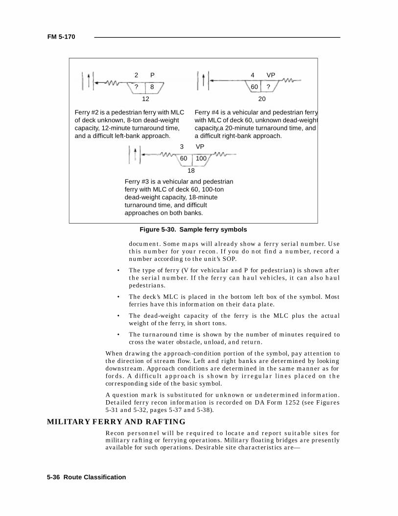
FM 5-170
document. Some maps will already show a ferry serial number. Usethis number for your recon. If you do not find a number, record anumber according to the unit’s SOP.
• The type of ferry (V for vehicular and P for pedestrian) is shown afterthe serial number. If the ferry can haul vehicles, it can also haulpedestrians.
• The deck’s MLC is placed in the bottom left box of the symbol. Mostferries have this information on their data plate.
• The dead-weight capacity of the ferry is the MLC plus the actualweight of the ferry, in short tons.
• The turnaround time is shown by the number of minutes required tocross the water obstacle, unload, and return.
When drawing the approach-condition portion of the symbol, pay attention tothe direction of stream flow. Left and right banks are determined by lookingdownstream. Approach conditions are determined in the same manner as forfords. A difficult approach is shown by irregular lines placed on thecorresponding side of the basic symbol.
A question mark is substituted for unknown or undetermined information.Detailed ferry recon information is recorded on DA Form 1252 (see Figures5-31 and 5-32, pages 5-37 and 5-38).
MILITARY FERRY AND RAFTINGRecon personnel will be required to locate and report suitable sites formilitary rafting or ferrying operations. Military floating bridges are presentlyavailable for such operations. Desirable site characteristics are—
Figure 5-30. Sample ferry symbols
2 P
? 8
12
4 VP
60 ?
20
3 VP
60 100
18
Ferry #2 is a pedestrian ferry with MLC of deck unknown, 8-ton dead-weight capacity, 12-minute turnaround time, and a difficult left-bank approach.
Ferry #4 is a vehicular and pedestrian ferrywith MLC of deck 60, unknown dead-weightcapacity,a 20-minute turnaround time, and a difficult right-bank approach.
Ferry #3 is a vehicular and pedestrian ferry with MLC of deck 60, 100-ton dead-weight capacity, 18-minute turnaround time, and difficult approaches on both banks.
5-36 Route Classification
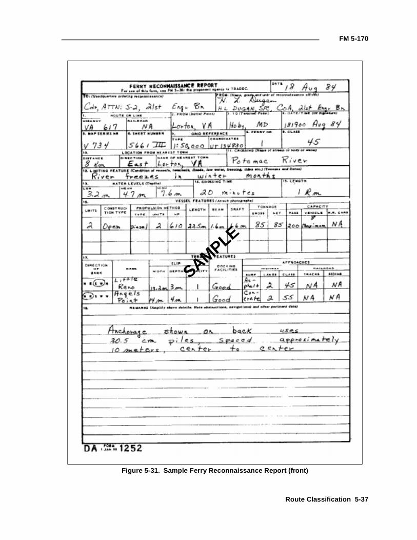
FM 5-170
Figure 5-31. Sample Ferry Reconnaissance Report (front)
SAMPLE
Route Classification 5-37
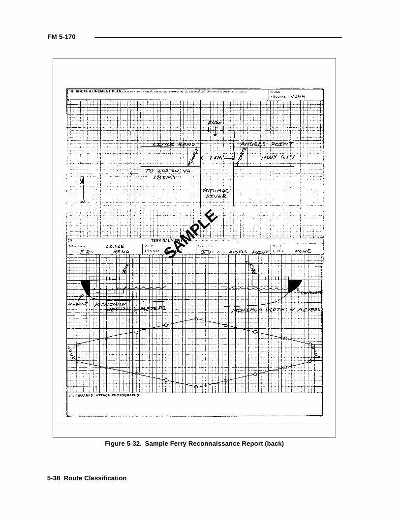
FM 5-170
Figure 5-32. Sample Ferry Reconnaissance Report (back)
SAMPLE
5-38 Route Classification
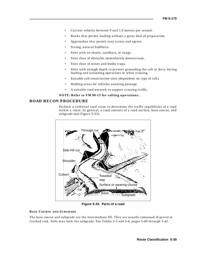
FM 5-170
• Current velocity between 0 and 1.6 meters per second.
• Banks that permit loading without a great deal of preparation.
• Approaches that permit easy access and egress.
• Strong, natural holdfasts.
• Sites with no shoals, sandbars, or snags.
• Sites clear of obstacles immediately downstream.
• Sites clear of mines and booby traps.
• Sites with enough depth to prevent grounding the raft or ferry duringloading and unloading operations or when crossing.
• Suitable raft-construction sites (dependent on type of raft).
• Holding areas for vehicles awaiting passage.
• A suitable road network to support crossing traffic.
NOTE: Refer to FM 90-13 for rafting operations.
ROAD RECON PROCEDUREPerform a technical road recon to determine the traffic capabilities of a roadwithin a route. In general, a road consists of a road surface, base course, andsubgrade (see Figure 5-33).
BASE COURSE AND SUBGRADE
The base course and subgrade are the intermediate fill. They are usually composed of gravel or crushed rock. Soils may form the subgrade. See Tables 5-3 and 5-4, pages 5-40 through 5-42.
Figure 5-33. Parts of a road
Through cut
Side-hill cut
Shoulder
Culvert Traveledway
Surface or wearing course
Subgrade
FillBase
Route Classification 5-39
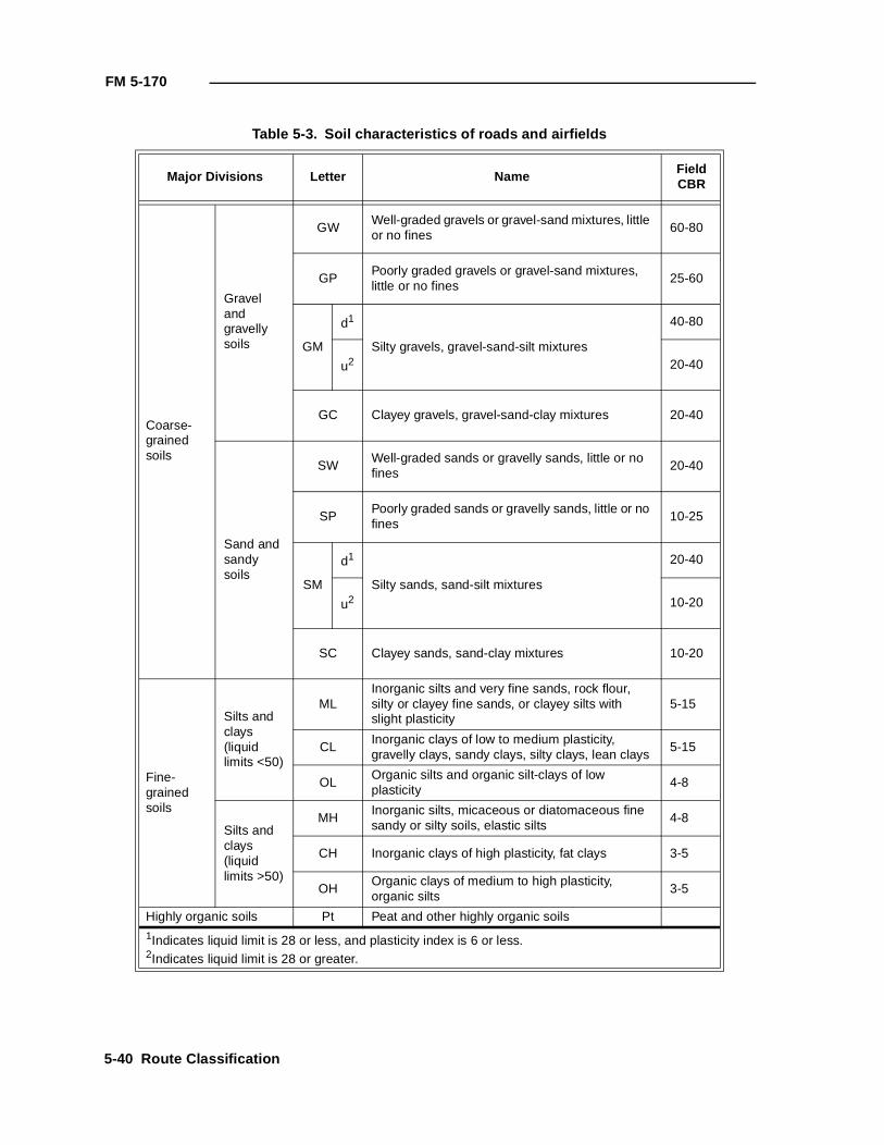
FM 5-170
Table 5-3. Soil characteristics of roads and airfields
Major Divisions Letter NameFieldCBR
Coarse-grained soils
Gravel and gravelly soils
GWWell-graded gravels or gravel-sand mixtures, little or no fines
60-80
GPPoorly graded gravels or gravel-sand mixtures, little or no fines
25-60
GM
d1
Silty gravels, gravel-sand-silt mixtures
40-80
u2 20-40
GC Clayey gravels, gravel-sand-clay mixtures 20-40
Sand and sandy soils
SWWell-graded sands or gravelly sands, little or no fines
20-40
SPPoorly graded sands or gravelly sands, little or no fines
10-25
SM
d1
Silty sands, sand-silt mixtures
20-40
u2 10-20
SC Clayey sands, sand-clay mixtures 10-20
Fine-grained soils
Silts and clays (liquid limits <50)
MLInorganic silts and very fine sands, rock flour, silty or clayey fine sands, or clayey silts with slight plasticity
5-15
CLInorganic clays of low to medium plasticity, gravelly clays, sandy clays, silty clays, lean clays
5-15
OLOrganic silts and organic silt-clays of low plasticity
4-8
Silts and clays (liquid limits >50)
MHInorganic silts, micaceous or diatomaceous fine sandy or silty soils, elastic silts
4-8
CH Inorganic clays of high plasticity, fat clays 3-5
OHOrganic clays of medium to high plasticity, organic silts
3-5
Highly organic soils Pt Peat and other highly organic soils
1Indicates liquid limit is 28 or less, and plasticity index is 6 or less.2Indicates liquid limit is 28 or greater.
5-40 Route Classification
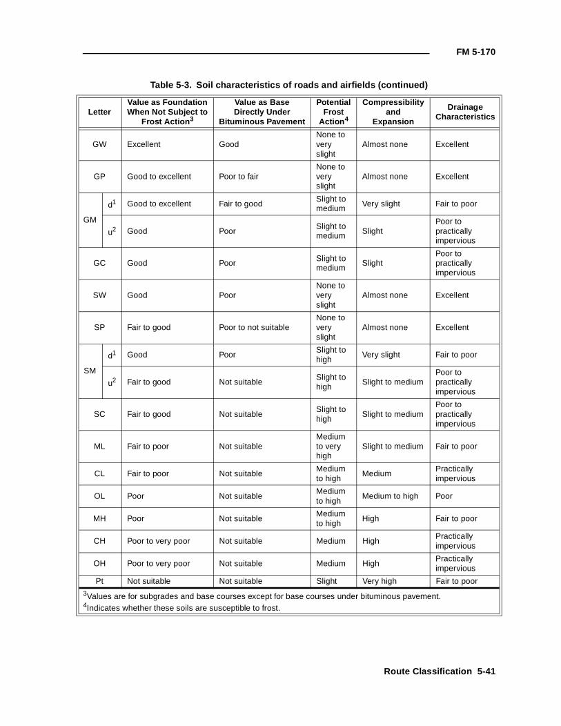
FM 5-170
Table 5-3. Soil characteristics of roads and airfields (continued)
LetterValue as FoundationWhen Not Subject to
Frost Action 3
Value as BaseDirectly Under
Bituminous Pavement
PotentialFrost
Action 4
Compressibilityand
Expansion
DrainageCharacteristics
GW Excellent GoodNone to very slight
Almost none Excellent
GP Good to excellent Poor to fairNone to very slight
Almost none Excellent
GM
d1 Good to excellent Fair to goodSlight to medium Very slight Fair to poor
u2 Good PoorSlight to medium Slight
Poor to practically impervious
GC Good Poor Slight to medium
SlightPoor to practically impervious
SW Good PoorNone to very slight
Almost none Excellent
SP Fair to good Poor to not suitableNone to very slight
Almost none Excellent
SM
d1 Good PoorSlight to high
Very slight Fair to poor
u2 Fair to good Not suitableSlight to high
Slight to mediumPoor to practically impervious
SC Fair to good Not suitable Slight to high
Slight to mediumPoor to practically impervious
ML Fair to poor Not suitableMedium to very high
Slight to medium Fair to poor
CL Fair to poor Not suitableMedium to high
MediumPractically impervious
OL Poor Not suitableMedium to high
Medium to high Poor
MH Poor Not suitableMedium to high
High Fair to poor
CH Poor to very poor Not suitable Medium HighPractically impervious
OH Poor to very poor Not suitable Medium HighPractically impervious
Pt Not suitable Not suitable Slight Very high Fair to poor
3Values are for subgrades and base courses except for base courses under bituminous pavement.4Indicates whether these soils are susceptible to frost.
Route Classification 5-41
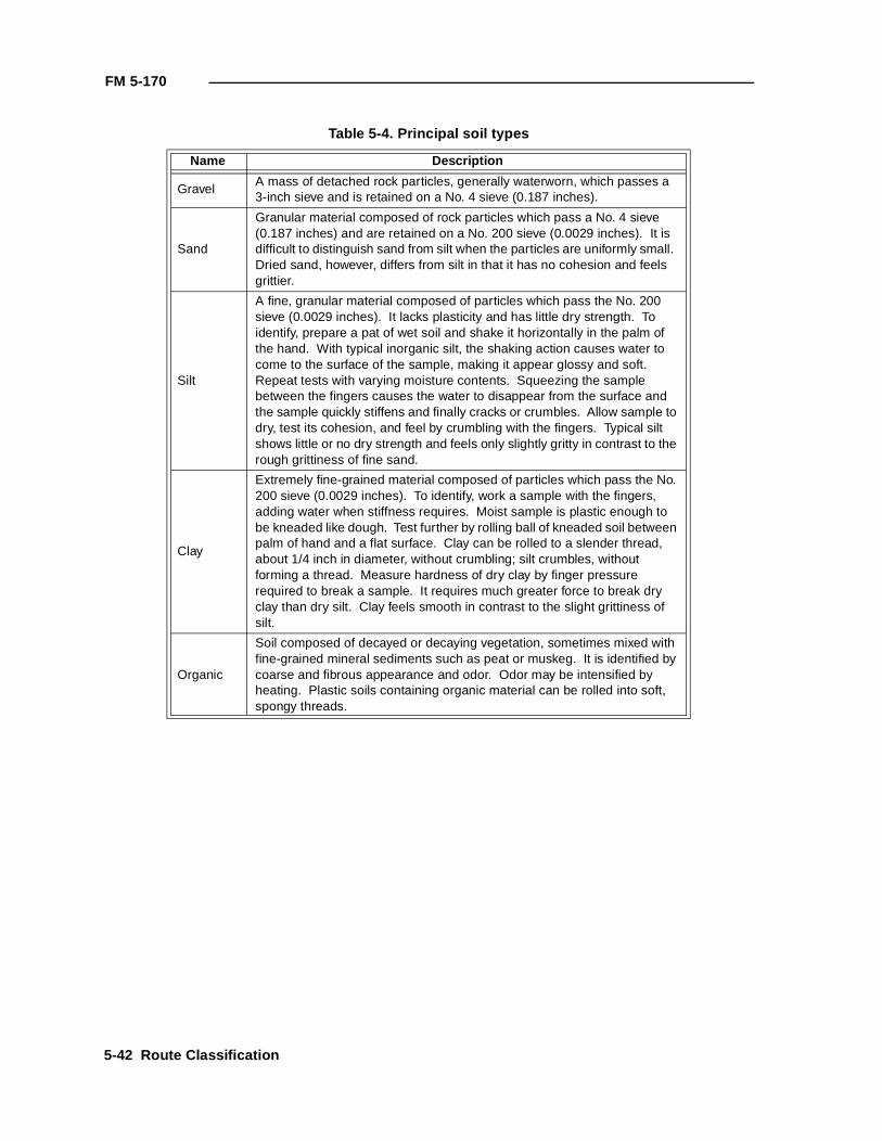
FM 5-170
Table 5-4. Principal soil types
Name Description
GravelA mass of detached rock particles, generally waterworn, which passes a 3-inch sieve and is retained on a No. 4 sieve (0.187 inches).
Sand
Granular material composed of rock particles which pass a No. 4 sieve (0.187 inches) and are retained on a No. 200 sieve (0.0029 inches). It is difficult to distinguish sand from silt when the particles are uniformly small. Dried sand, however, differs from silt in that it has no cohesion and feels grittier.
Silt
A fine, granular material composed of particles which pass the No. 200 sieve (0.0029 inches). It lacks plasticity and has little dry strength. To identify, prepare a pat of wet soil and shake it horizontally in the palm of the hand. With typical inorganic silt, the shaking action causes water to come to the surface of the sample, making it appear glossy and soft. Repeat tests with varying moisture contents. Squeezing the sample between the fingers causes the water to disappear from the surface and the sample quickly stiffens and finally cracks or crumbles. Allow sample to dry, test its cohesion, and feel by crumbling with the fingers. Typical silt shows little or no dry strength and feels only slightly gritty in contrast to the rough grittiness of fine sand.
Clay
Extremely fine-grained material composed of particles which pass the No. 200 sieve (0.0029 inches). To identify, work a sample with the fingers, adding water when stiffness requires. Moist sample is plastic enough to be kneaded like dough. Test further by rolling ball of kneaded soil between palm of hand and a flat surface. Clay can be rolled to a slender thread, about 1/4 inch in diameter, without crumbling; silt crumbles, without forming a thread. Measure hardness of dry clay by finger pressure required to break a sample. It requires much greater force to break dry clay than dry silt. Clay feels smooth in contrast to the slight grittiness of silt.
Organic
Soil composed of decayed or decaying vegetation, sometimes mixed with fine-grained mineral sediments such as peat or muskeg. It is identified by coarse and fibrous appearance and odor. Odor may be intensified by heating. Plastic soils containing organic material can be rolled into soft, spongy threads.
5-42 Route Classification
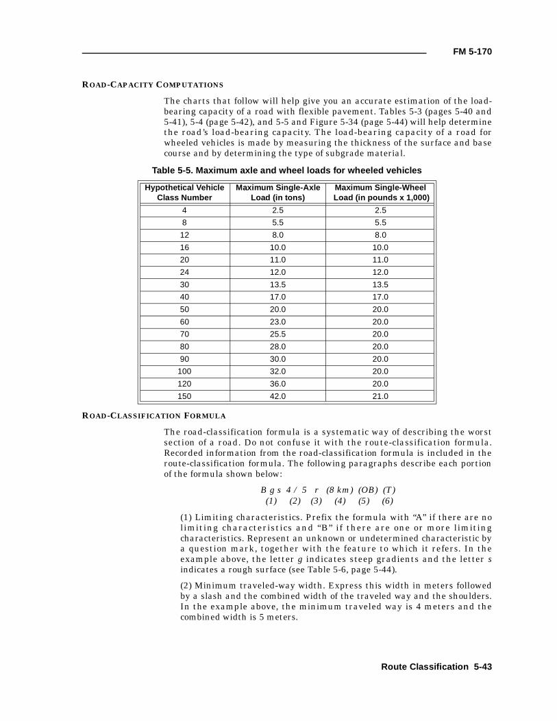
FM 5-170
ROAD-CAPACITY COMPUTATIONS
The charts that follow will help give you an accurate estimation of the load-bearing capacity of a road with flexible pavement. Tables 5-3 (pages 5-40 and5-41), 5-4 (page 5-42), and 5-5 and Figure 5-34 (page 5-44) will help determinethe road’s load-bearing capacity. The load-bearing capacity of a road forwheeled vehicles is made by measuring the thickness of the surface and basecourse and by determining the type of subgrade material.
ROAD-CLASSIFICATION FORMULA
The road-classification formula is a systematic way of describing the worstsection of a road. Do not confuse it with the route-classification formula.Recorded information from the road-classification formula is included in theroute-classification formula. The following paragraphs describe each portionof the formula shown below:
B g s 4 / 5 r (8 km) (OB) (T) (1) (2) (3) (4) (5) (6)
(1) Limiting characteristics. Prefix the formula with “A” if there are nolimiting characteristics and “B” if there are one or more limitingcharacteristics. Represent an unknown or undetermined characteristic bya question mark, together with the feature to which it refers. In theexample above, the letter g indicates steep gradients and the letter sindicates a rough surface (see Table 5-6, page 5-44).
(2) Minimum traveled-way width. Express this width in meters followedby a slash and the combined width of the traveled way and the shoulders.In the example above, the minimum traveled way is 4 meters and thecombined width is 5 meters.
Table 5-5. Maximum axle and wheel loads for wheeled vehicles
Hypothetical VehicleClass Number
Maximum Single-AxleLoad (in tons)
Maximum Single-Wheel Load (in pounds x 1,000)
4 2.5 2.5
8 5.5 5.5
12 8.0 8.0
16 10.0 10.0
20 11.0 11.0
24 12.0 12.0
30 13.5 13.5
40 17.0 17.0
50 20.0 20.0
60 23.0 20.0
70 25.5 20.0
80 28.0 20.0
90 30.0 20.0
100 32.0 20.0
120 36.0 20.0
150 42.0 21.0
Route Classification 5-43
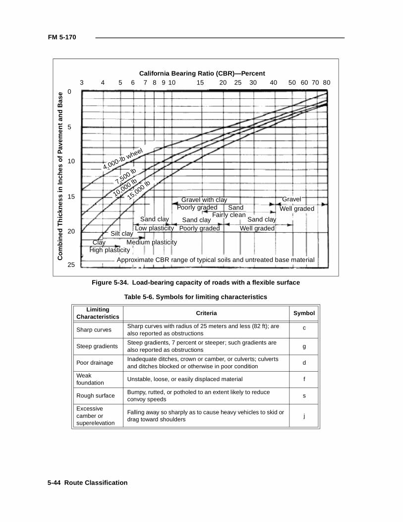
FM 5-170
Figure 5-34. Load-bearing capacity of roads with a flexible surface
Table 5-6. Symbols for limiting characteristics
LimitingCharacteristics
Criteria Symbol
Sharp curvesSharp curves with radius of 25 meters and less (82 ft); are also reported as obstructions
c
Steep gradientsSteep gradients, 7 percent or steeper; such gradients are also reported as obstructions
g
Poor drainageInadequate ditches, crown or camber, or culverts; culverts and ditches blocked or otherwise in poor condition
d
Weak foundation
Unstable, loose, or easily displaced material f
Rough surfaceBumpy, rutted, or potholed to an extent likely to reduce convoy speeds
s
Excessive camber or superelevation
Falling away so sharply as to cause heavy vehicles to skid or drag toward shoulders
j
California Bearing Ratio (CBR)—Percent
Com
bine
d T
hick
ness
in In
ches
of P
avem
ent a
nd B
ase
3 4 5 6 7 8 9 10 15 20 25 30 40 50 60 70 800
5
10
15
20
25
4,000-lb wheel
7,500 lb
10,000 lb
15,000 lb
Gravel with clay GravelPoorly graded Sand Well graded
Fairly cleanSand clay Sand clay Sand clay
Poorly graded Well gradedLow plasticitySilt clay
Medium plasticityClayHigh plasticity
Approximate CBR range of typical soils and untreated base material
5-44 Route Classification
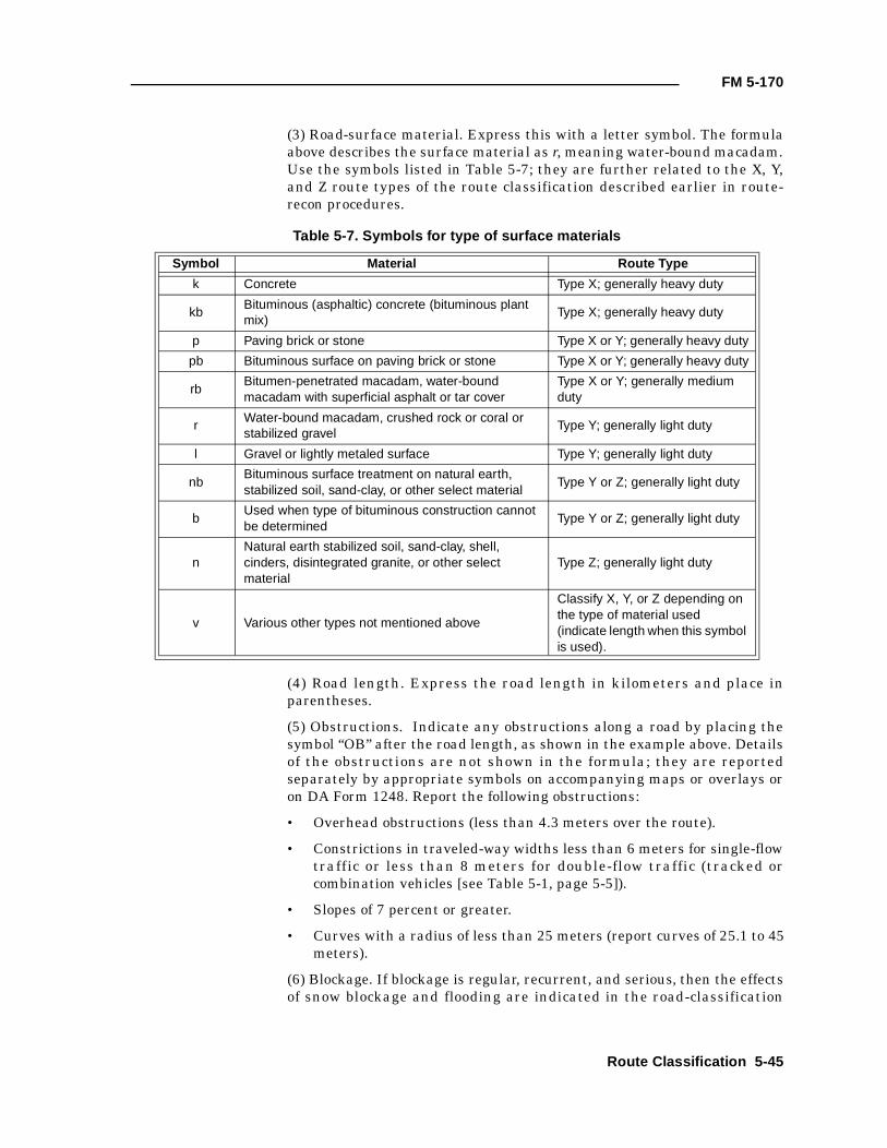
FM 5-170
(3) Road-surface material. Express this with a letter symbol. The formulaabove describes the surface material as r, meaning water-bound macadam.Use the symbols listed in Table 5-7; they are further related to the X, Y,and Z route types of the route classification described earlier in route-recon procedures.
(4) Road length. Express the road length in kilometers and place inparentheses.
(5) Obstructions. Indicate any obstructions along a road by placing thesymbol “OB” after the road length, as shown in the example above. Detailsof the obstructions are not shown in the formula; they are reportedseparately by appropriate symbols on accompanying maps or overlays oron DA Form 1248. Report the following obstructions:
• Overhead obstructions (less than 4.3 meters over the route).
• Constrictions in traveled-way widths less than 6 meters for single-flowtraffic or less than 8 meters for double-flow traffic (tracked orcombination vehicles [see Table 5-1, page 5-5]).
• Slopes of 7 percent or greater.
• Curves with a radius of less than 25 meters (report curves of 25.1 to 45meters).
(6) Blockage. If blockage is regular, recurrent, and serious, then the effectsof snow blockage and flooding are indicated in the road-classification
Table 5-7. Symbols for type of surface materials
Symbol Material Route Type
k Concrete Type X; generally heavy duty
kbBituminous (asphaltic) concrete (bituminous plant mix)
Type X; generally heavy duty
p Paving brick or stone Type X or Y; generally heavy duty
pb Bituminous surface on paving brick or stone Type X or Y; generally heavy duty
rbBitumen-penetrated macadam, water-bound macadam with superficial asphalt or tar cover
Type X or Y; generally medium duty
rWater-bound macadam, crushed rock or coral or stabilized gravel
Type Y; generally light duty
l Gravel or lightly metaled surface Type Y; generally light duty
nbBituminous surface treatment on natural earth, stabilized soil, sand-clay, or other select material
Type Y or Z; generally light duty
bUsed when type of bituminous construction cannot be determined
Type Y or Z; generally light duty
nNatural earth stabilized soil, sand-clay, shell, cinders, disintegrated granite, or other select material
Type Z; generally light duty
v Various other types not mentioned above
Classify X, Y, or Z depending on the type of material used (indicate length when this symbol is used).
Route Classification 5-45
FM 5-170
formula. The symbol for snow blockage is “T” and the symbol for frequentflooding is “W.”
EXAMPLES OF THE ROAD-CLASSIFICATION FORMULA
A sample Road Reconnaissance Report is shown in Figures 5-35 and 5-36,pages 5-47 and 5-48. The following are examples of the road-classificationformula:
• A 5.0/6.2k—road with no limiting characteristics or obstructions, aminimum traveled way of 5.0 meters, a combined width of traveledway and shoulders of 6.2 meters, and a concrete surface.
• B g s 4/5 1 (OB)—road with limiting characteristics of steep gradientsand a rough surface, a minimum traveled way of 4 meters, a combinedwidth of 5 meters, gravel or lightly metaled surfaces, and obstructions.
• B c (f?) 3.2/4.8 p (4.3km) (OB) (T)—road with limitingcharacteristics of sharp curves and unknown foundation, a minimumtraveled way of 3.2 meters, a combined width of 4.8 meters, pavingbrick or stone surface, obstructions and that is 4.3 kilometerslongsubject to snow blockage.
NOTES:
1. Where rock slides are a hazard or poor drainage is a problem,include information on a written enclosure or legend.
2. DA Form 1248 is primarily self-explanatory. However, ensure that anew classification formula is entered each time the road changessignificantly, as depicted in Figure 5-36.
BRIDGE-CLASSIFICATION RECON
A bridge recon must take place to ensure that commanders know what bridgeload-carrying capabilities are along a certain route or what material is neededto destroy a bridge. Engineers are responsible for reconning all bridges.
REQUIRED BRIDGE INFORMATION FOR CLASSIFICATION PROCEDURES
This manual reviews the basics of hasty bridge load-classification proceduresand recon procedures for bridge destruction. Appendix B references hastybridge classification. (Refer to FM 5-446 for a complete discussion of bridge-classification procedures.) The Sheffield Method for bridge destruction isdiscussed in FM 5-250.
The method of bridge load classification covered in Appendix B is adequate formost bridge recons. It allows vehicle operators to avoid bridge failure bydetermining what can cross the bridge without causing damage. Vehicleoperators may cross without restrictions if their vehicle’s load class (includingthe load) is less than or equal to the bridge’s load class. The vehicle’s load classcan be found in the vehicle’s TM.
5-46 Route Classification
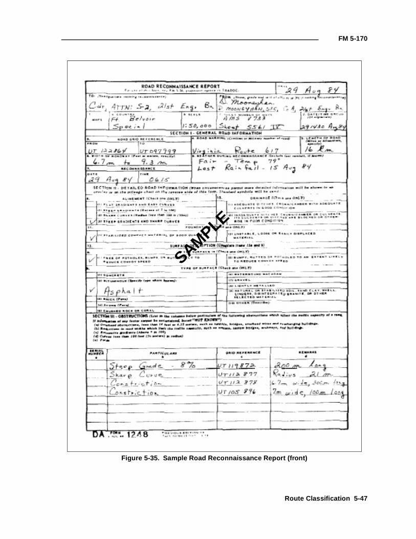
FM 5-170
Figure 5-35. Sample Road Reconnaissance Report (front)
SAMPLE
Route Classification 5-47
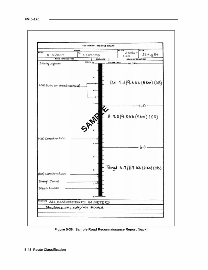
FM 5-170
Figure 5-36. Sample Road Reconnaissance Report (back)
SAMPLE
5-48 Route Classification
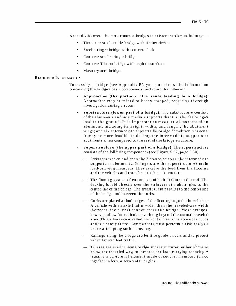
FM 5-170
Appendix B covers the most common bridges in existence today, including a—
• Timber or steel trestle bridge with timber deck.
• Steel-stringer bridge with concrete deck.
• Concrete steel-stringer bridge.
• Concrete T-beam bridge with asphalt surface.
• Masonry arch bridge.
REQUIRED INFORMATION
To classify a bridge (see Appendix B), you must know the informationconcerning the bridge’s basic components, including the following:
• Approaches (the portions of a route leading to a bridge).Approaches may be mined or booby trapped, requiring thoroughinvestigation during a recon.
• Substructure (lower part of a bridge). The substructure consistsof the abutments and intermediate supports that transfer the bridge’sload to the ground. It is important to measure all aspects of anabutment, including its height, width, and length; the abutmentwings; and the intermediate supports for bridge demolition missions.It may be more feasible to destroy the intermediate supports orabutments when compared to the rest of the bridge structure.
• Superstructure (the upper part of a bridge). The superstructureconsists of the following components (see Figure 5-37, page 5-50):
— Stringers rest on and span the distance between the intermediatesupports or abutments. Stringers are the superstructure’s mainload-carrying members. They receive the load from the flooringand the vehicles and transfer it to the substructure.
— The flooring system often consists of both decking and tread. Thedecking is laid directly over the stringers at right angles to thecenterline of the bridge. The tread is laid parallel to the centerlineof the bridge and between the curbs.
— Curbs are placed at both edges of the flooring to guide the vehicles.A vehicle with an axle that is wider than the traveled-way width(between the curbs) cannot cross the bridge. Most bridges,however, allow for vehicular overhang beyond the normal traveledarea. This allowance is called horizontal clearance above the curbsand is a safety factor. Commanders must perform a risk analysisbefore attempting such a crossing.
— Railings along the bridge are built to guide drivers and to protectvehicular and foot traffic.
— Trusses are used in some bridge superstructures, either above orbelow the traveled way, to increase the load-carrying capacity. Atruss is a structural element made of several members joinedtogether to form a series of triangles.
Route Classification 5-49
FM 5-170
— The number of members in each span is noted where applicable(for example, stringer bridges and concrete T-beam bridges). Exactdimensions of specific bridge members are taken as outlined laterin this chapter.
— The span length is measured from center to center of the supports.The bridge’s classification is usually based on the weakest span. Ifthe weakest span is apparent, no other spans need to be reconned.However, if the weakest span is difficult or impossible to locate, allspans must be classified. Even if several spans look identical,actual measurements should be taken to prevent error.
Figure 5-37. Bridge parts
Superstructure (upper part)
Superstructure (lower part)
Truss
Decking
CurbHandrail
Tread
Abutment
Intermediate support
Stringer
Truss Truss
Traveled way
Fill
Abutment Abutment
Cut
b
a ad
c c
a = Approachb = Overall lengthc = Span length, bearing to bearingd = Length, abutment to abutment
Intermediatesupport
5-50 Route Classification
FM 5-170
— The traveled-way width is measured between the inside faces ofthe curbs. However, the horizontal clearance on a truss bridge ismeasured from a point 1.21 meters above the roadway.
BRIDGE CONDITION
It is essential to note the bridge’s general condition, paying particularattention to evidence of damage from natural causes (rot, rust, anddeterioration) or combat action. Classification procedures presume that abridge is in good condition. If the bridge is in poor condition, the class obtainedfrom mathematical computations must be reduced according to the classifier’sjudgment.
WIDTH AND HEIGHT RESTRICTIONS
Table 5-8 lists width restrictions for bridges. If a one-lane bridge does not meetwidth requirements, post a rectangular warning sign under the classificationsign showing the actual clear width (see Figure 5-38, page 5-52). If this is aroute restriction, annotate it in the route-classification formula. For a two-lane bridge, downgrade the two-way classification to the highest class forwhich it does qualify (one-way class is not affected). Post a limited-clearancesign if the overhead clearance is less than 4.3 meters. These signs must be aminimum of 40 centimeters in height or width, with a yellow background, andthe appropriate description in black letters. Separate rectangular signs areused if necessary to denote width limitations, height limitations, or othertechnical information. The same signs are used for tunnels, if applicable.
BRIDGE TRAFFIC-CONTROL PROCEDURE
Posting standard bridge signs and other signs needed for proper and efficienttraffic control across a bridge is an engineer’s responsibility. Additional signsare used when it is necessary to warn vehicles that require special controlswhile crossing. When necessary, holding areas, turnouts for parking andunloading vehicles, and checkpoints are installed near bridges to provide thenecessary control during crossings.
Table 5-8. Minimum roadway widths
Roadway Width(meters)
Bridge Classification
One-Way Two-Way
2.75 to 3.34 12 0
3.35 to 3.99 30 0
4 to 4.49 60 0
4.5 to 4.99 100 0
5 to 5.4 150 0
5.5 to 7.2 150 30
7.3 to 8.1 150 60
8.2 to 9.7 150 100
Over 9.8 150 150
NOTE: Minimum overhead clearance for all classes is 4.3 meters
Route Classification 5-51
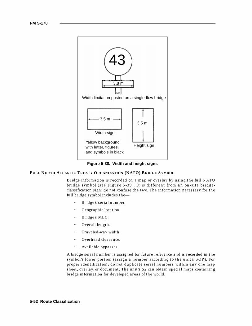
FM 5-170
FULL NORTH ATLANTIC TREATY ORGANIZATION (NATO) BRIDGE SYMBOL
Bridge information is recorded on a map or overlay by using the full NATObridge symbol (see Figure 5-39). It is different from an on-site bridge-classification sign; do not confuse the two. The information necessary for thefull bridge symbol includes the—
• Bridge’s serial number.
• Geographic location.
• Bridge’s MLC.
• Overall length.
• Traveled-way width.
• Overhead clearance.
• Available bypasses.
A bridge serial number is assigned for future reference and is recorded in thesymbol’s lower portion (assign a number according to the unit’s SOP). Forproper identification, do not duplicate serial numbers within any one mapsheet, overlay, or document. The unit’s S2 can obtain special maps containingbridge information for developed areas of the world.
Figure 5-38. Width and height signs
433.8 m
Width limitation posted on a single-flow bridge
3.5 m3.5 m
Width sign
Height signYellow background with letter, figures, and symbols in black
5-52 Route Classification
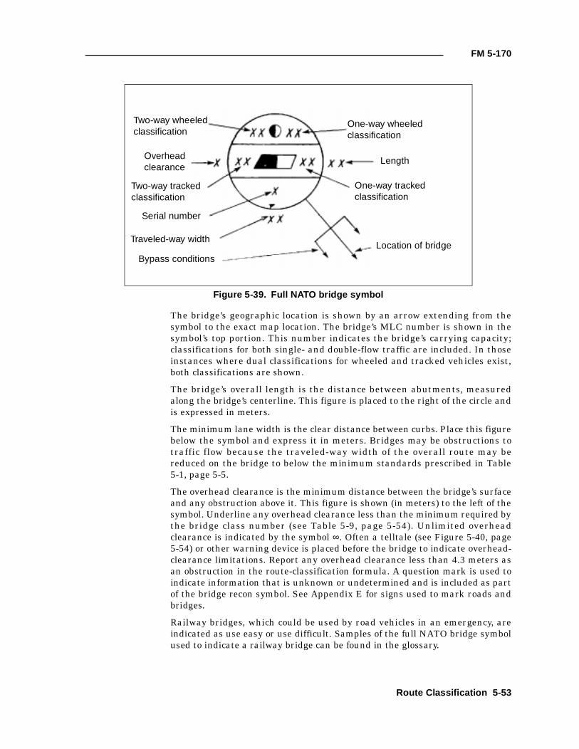
FM 5-170
The bridge’s geographic location is shown by an arrow extending from thesymbol to the exact map location. The bridge’s MLC number is shown in thesymbol’s top portion. This number indicates the bridge’s carrying capacity;classifications for both single- and double-flow traffic are included. In thoseinstances where dual classifications for wheeled and tracked vehicles exist,both classifications are shown.
The bridge’s overall length is the distance between abutments, measuredalong the bridge’s centerline. This figure is placed to the right of the circle andis expressed in meters.
The minimum lane width is the clear distance between curbs. Place this figurebelow the symbol and express it in meters. Bridges may be obstructions totraffic flow because the traveled-way width of the overall route may bereduced on the bridge to below the minimum standards prescribed in Table5-1, page 5-5.
The overhead clearance is the minimum distance between the bridge’s surfaceand any obstruction above it. This figure is shown (in meters) to the left of thesymbol. Underline any overhead clearance less than the minimum required bythe bridge class number (see Table 5-9, page 5-54). Unlimited overheadclearance is indicated by the symbol ∞. Often a telltale (see Figure 5-40, page5-54) or other warning device is placed before the bridge to indicate overhead-clearance limitations. Report any overhead clearance less than 4.3 meters asan obstruction in the route-classification formula. A question mark is used toindicate information that is unknown or undetermined and is included as partof the bridge recon symbol. See Appendix E for signs used to mark roads andbridges.
Railway bridges, which could be used by road vehicles in an emergency, areindicated as use easy or use difficult. Samples of the full NATO bridge symbolused to indicate a railway bridge can be found in the glossary.
Figure 5-39. Full NATO bridge symbol
Two-way wheeledclassification
One-way wheeled classification
Overhead clearance
Two-way tracked classification
One-way tracked classification
Serial number
Traveled-way width
Bypass conditionsLocation of bridge
Length
Route Classification 5-53
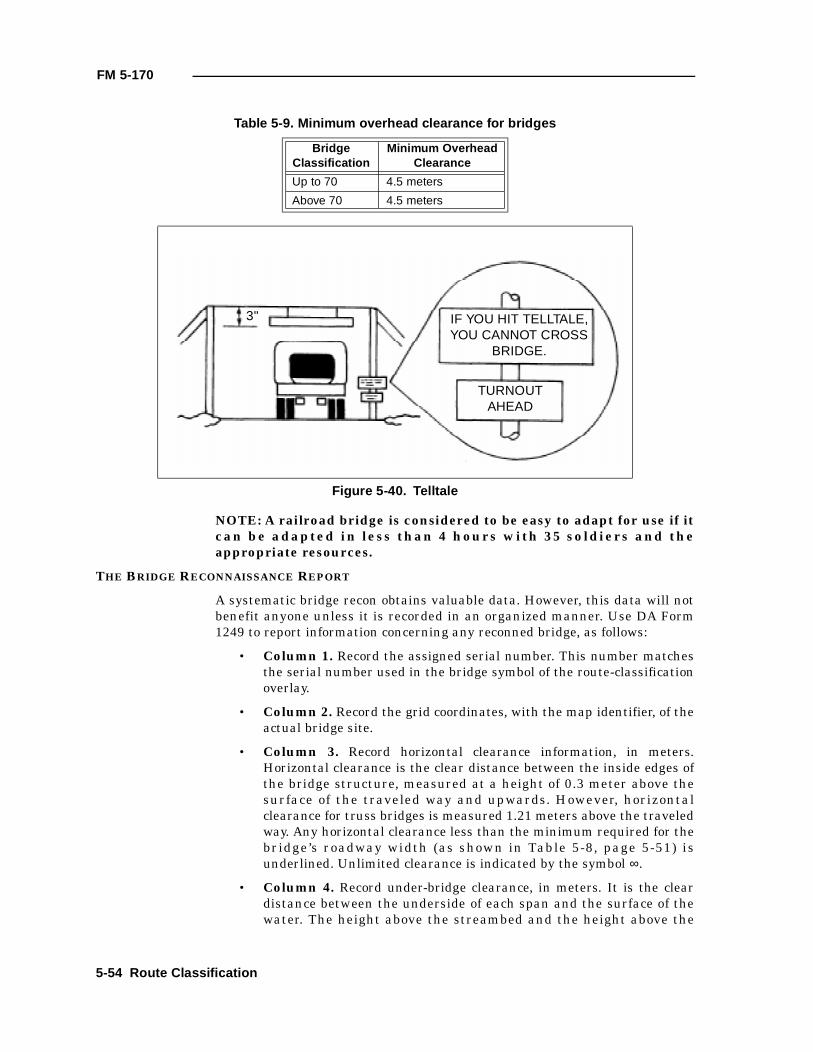
FM 5-170
NOTE: A railroad bridge is considered to be easy to adapt for use if itcan be adapted in less than 4 hours with 35 soldiers and theappropriate resources.
THE BRIDGE RECONNAISSANCE REPORT
A systematic bridge recon obtains valuable data. However, this data will notbenefit anyone unless it is recorded in an organized manner. Use DA Form1249 to report information concerning any reconned bridge, as follows:
• Column 1. Record the assigned serial number. This number matchesthe serial number used in the bridge symbol of the route-classificationoverlay.
• Column 2. Record the grid coordinates, with the map identifier, of theactual bridge site.
• Column 3. Record horizontal clearance information, in meters.Horizontal clearance is the clear distance between the inside edges ofthe bridge structure, measured at a height of 0.3 meter above thesurface of the traveled way and upwards. However, horizontalclearance for truss bridges is measured 1.21 meters above the traveledway. Any horizontal clearance less than the minimum required for thebridge’s roadway width (as shown in Table 5-8, page 5-51) isunderlined. Unlimited clearance is indicated by the symbol ∞.
• Column 4. Record under-bridge clearance, in meters. It is the cleardistance between the underside of each span and the surface of thewater. The height above the streambed and the height above the
Table 5-9. Minimum overhead clearance for bridges
BridgeClassification
Minimum OverheadClearance
Up to 70 4.5 meters
Above 70 4.5 meters
Figure 5-40. Telltale
3" IF YOU HIT TELLTALE, YOU CANNOT CROSS
BRIDGE.
TURNOUTAHEAD
5-54 Route Classification
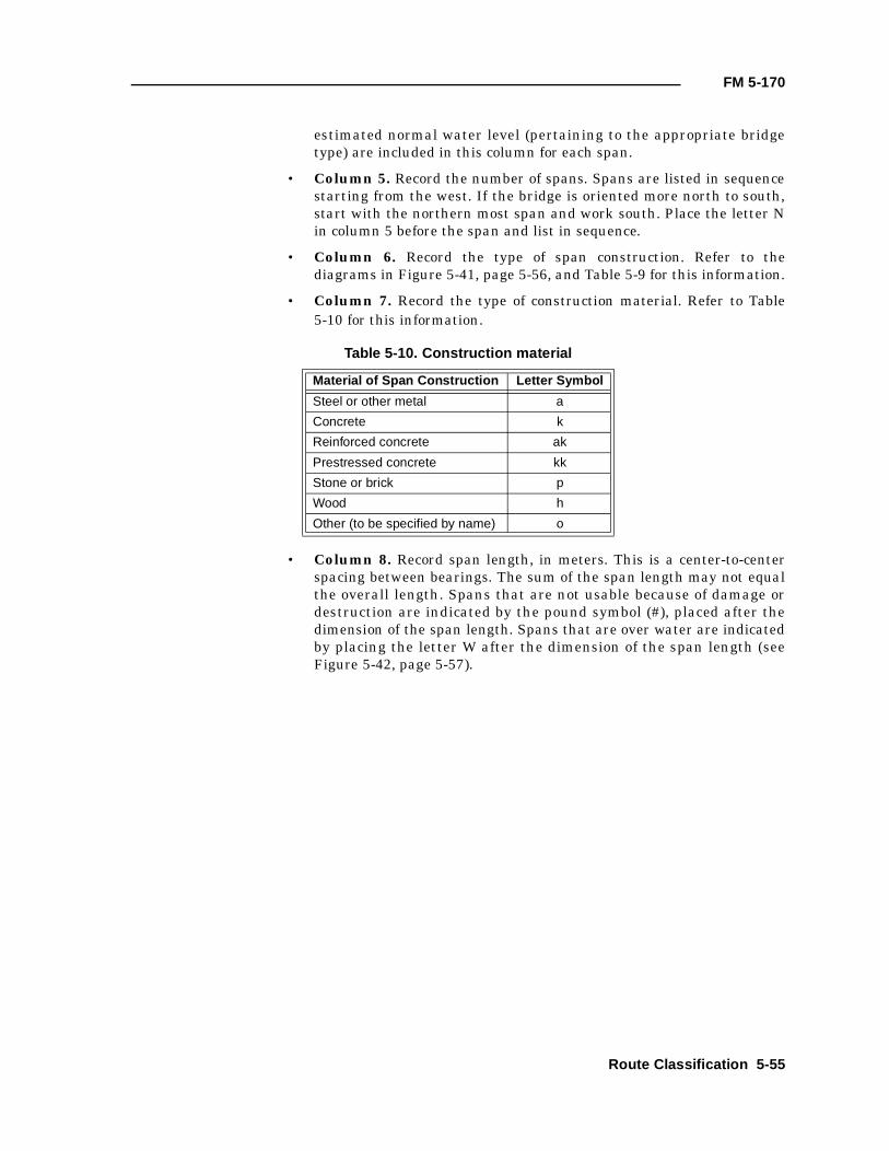
FM 5-170
estimated normal water level (pertaining to the appropriate bridgetype) are included in this column for each span.
• Column 5. Record the number of spans. Spans are listed in sequencestarting from the west. If the bridge is oriented more north to south,start with the northern most span and work south. Place the letter Nin column 5 before the span and list in sequence.
• Column 6. Record the type of span construction. Refer to thediagrams in Figure 5-41, page 5-56, and Table 5-9 for this information.
• Column 7. Record the type of construction material. Refer to Table5-10 for this information.
• Column 8. Record span length, in meters. This is a center-to-centerspacing between bearings. The sum of the span length may not equalthe overall length. Spans that are not usable because of damage ordestruction are indicated by the pound symbol (#), placed after thedimension of the span length. Spans that are over water are indicatedby placing the letter W after the dimension of the span length (seeFigure 5-42, page 5-57).
Table 5-10. Construction material
Material of Span Construction Letter Symbol
Steel or other metal a
Concrete k
Reinforced concrete ak
Prestressed concrete kk
Stone or brick p
Wood h
Other (to be specified by name) o
Route Classification 5-55
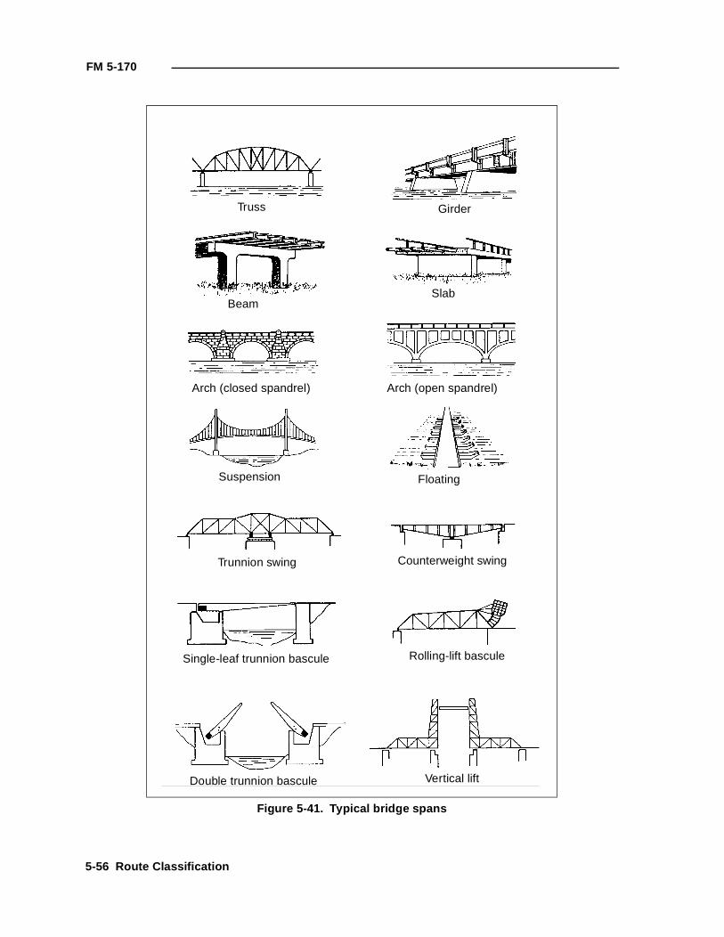
FM 5-170
Figure 5-41. Typical bridge spans
Truss Girder
BeamSlab
Arch (closed spandrel) Arch (open spandrel)
Suspension Floating
Trunnion swing Counterweight swing
Single-leaf trunnion bascule Rolling-lift bascule
Double trunnion bascule Vertical lift
5-56 Route Classification
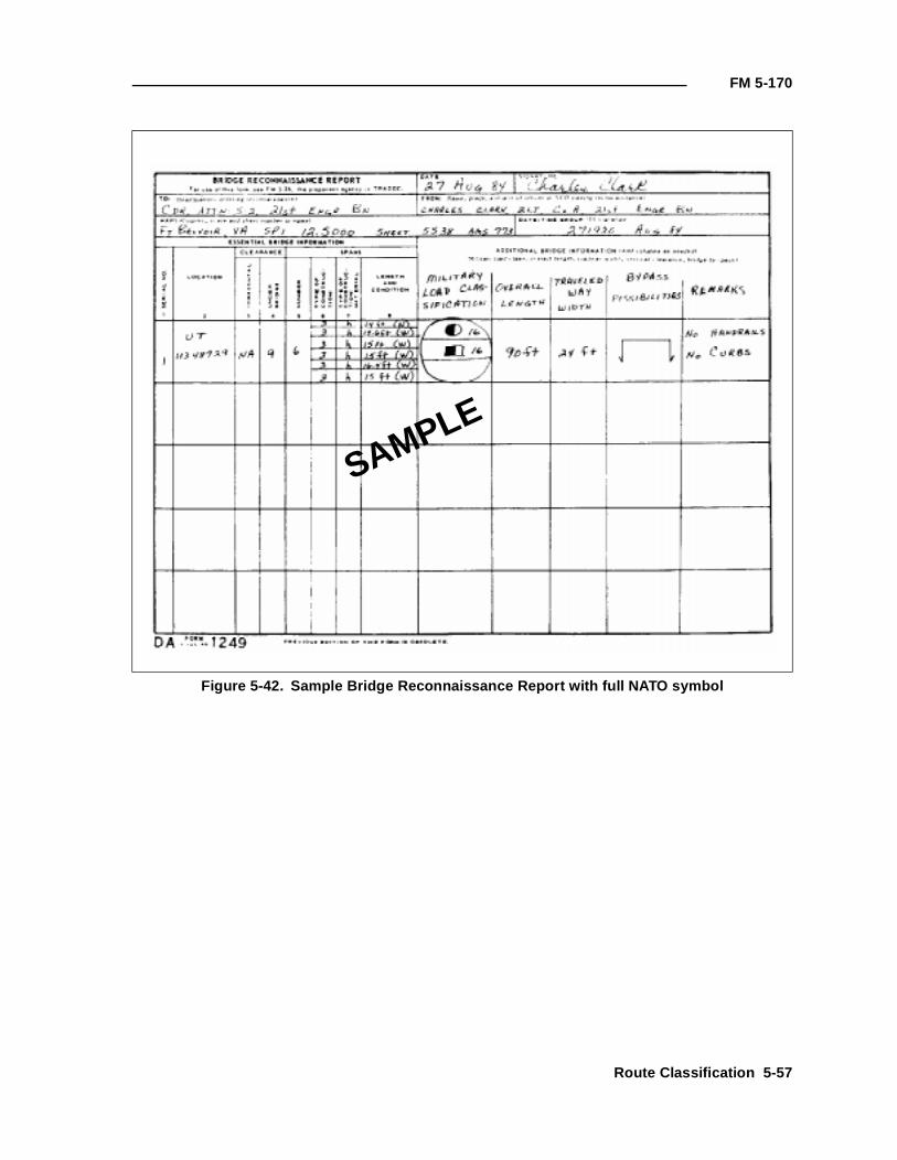
FM 5-170
Figure 5-42. Sample Bridge Reconnaissance Report with full NATO symbol
SAMPLE
Route Classification 5-57
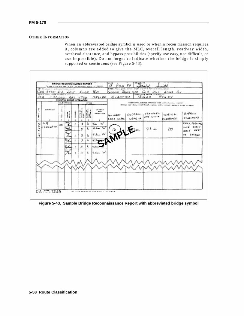
FM 5-170
OTHER INFORMATION
When an abbreviated bridge symbol is used or when a recon mission requiresit, columns are added to give the MLC, overall length, roadway width,overhead clearance, and bypass possibilities (specify use easy, use difficult, oruse impossible). Do not forget to indicate whether the bridge is simplysupported or continuous (see Figure 5-43).
Figure 5-43. Sample Bridge Reconnaissance Report with abbreviated bridge symbol
SAMPLE
5-58 Route Classification
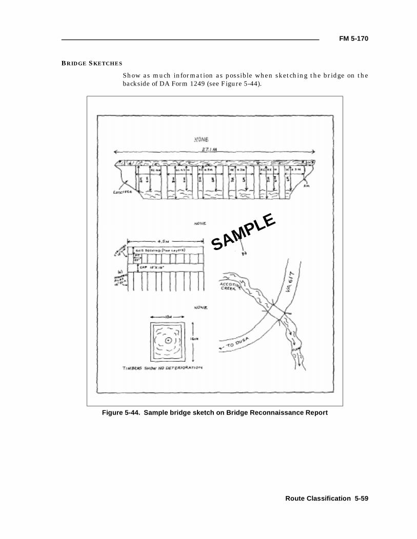
FM 5-170
BRIDGE SKETCHES
Show as much information as possible when sketching the bridge on thebackside of DA Form 1249 (see Figure 5-44).
Figure 5-44. Sample bridge sketch on Bridge Reconnaissance Report
SAMPLE
Route Classification 5-59
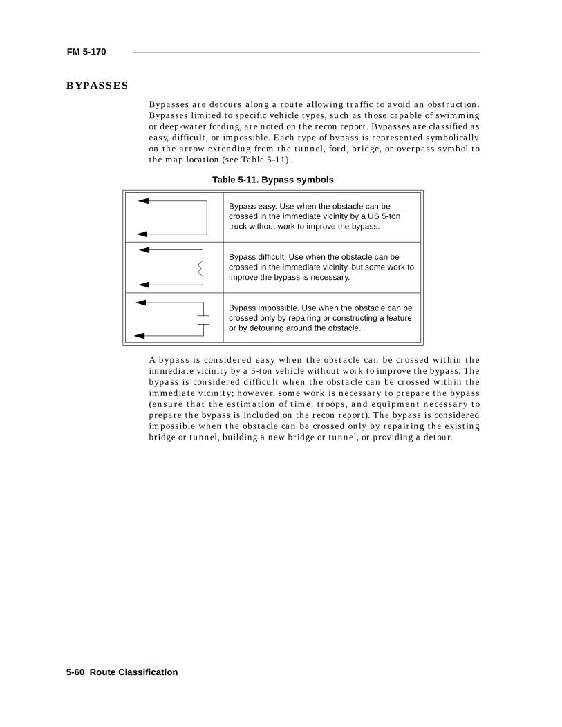
FM 5-170
BYPASSES
Bypasses are detours along a route allowing traffic to avoid an obstruction.Bypasses limited to specific vehicle types, such as those capable of swimmingor deep-water fording, are noted on the recon report. Bypasses are classified aseasy, difficult, or impossible. Each type of bypass is represented symbolicallyon the arrow extending from the tunnel, ford, bridge, or overpass symbol tothe map location (see Table 5-11).
A bypass is considered easy when the obstacle can be crossed within theimmediate vicinity by a 5-ton vehicle without work to improve the bypass. Thebypass is considered difficult when the obstacle can be crossed within theimmediate vicinity; however, some work is necessary to prepare the bypass(ensure that the estimation of time, troops, and equipment necessary toprepare the bypass is included on the recon report). The bypass is consideredimpossible when the obstacle can be crossed only by repairing the existingbridge or tunnel, building a new bridge or tunnel, or providing a detour.
Table 5-11. Bypass symbols
Bypass easy. Use when the obstacle can be crossed in the immediate vicinity by a US 5-ton truck without work to improve the bypass.
Bypass difficult. Use when the obstacle can be crossed in the immediate vicinity, but some work to improve the bypass is necessary.
Bypass impossible. Use when the obstacle can be crossed only by repairing or constructing a feature or by detouring around the obstacle.
5-60 Route Classification
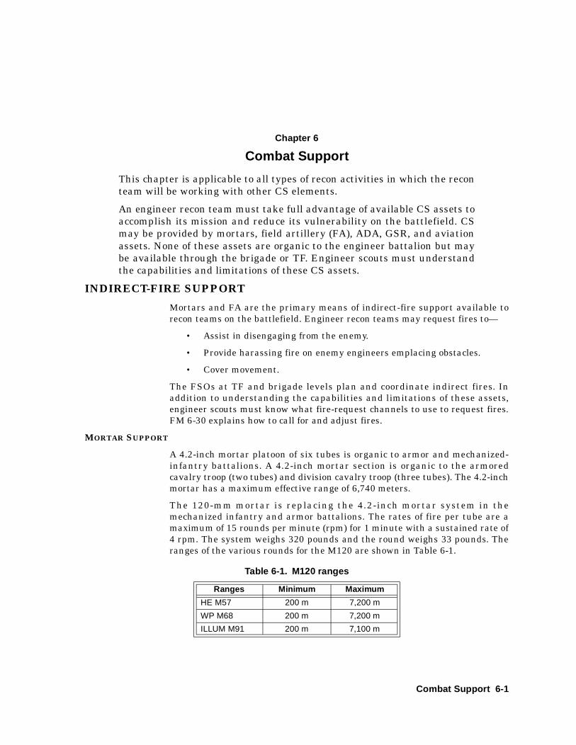
Chapter 6
Combat Support
This chapter is applicable to all types of recon activities in which the reconteam will be working with other CS elements.
An engineer recon team must take full advantage of available CS assets toaccomplish its mission and reduce its vulnerability on the battlefield. CSmay be provided by mortars, field artillery (FA), ADA, GSR, and aviationassets. None of these assets are organic to the engineer battalion but maybe available through the brigade or TF. Engineer scouts must understandthe capabilities and limitations of these CS assets.
INDIRECT-FIRE SUPPORT
Mortars and FA are the primary means of indirect-fire support available torecon teams on the battlefield. Engineer recon teams may request fires to—
• Assist in disengaging from the enemy.
• Provide harassing fire on enemy engineers emplacing obstacles.
• Cover movement.
The FSOs at TF and brigade levels plan and coordinate indirect fires. Inaddition to understanding the capabilities and limitations of these assets,engineer scouts must know what fire-request channels to use to request fires.FM 6-30 explains how to call for and adjust fires.
MORTAR SUPPORT
A 4.2-inch mortar platoon of six tubes is organic to armor and mechanized-infantry battalions. A 4.2-inch mortar section is organic to the armoredcavalry troop (two tubes) and division cavalry troop (three tubes). The 4.2-inchmortar has a maximum effective range of 6,740 meters.
The 120-mm mortar is replacing the 4.2-inch mortar system in themechanized infantry and armor battalions. The rates of fire per tube are amaximum of 15 rounds per minute (rpm) for 1 minute with a sustained rate of4 rpm. The system weighs 320 pounds and the round weighs 33 pounds. Theranges of the various rounds for the M120 are shown in Table 6-1.
Table 6-1. M120 ranges
Ranges Minimum Maximum
HE M57 200 m 7,200 m
WP M68 200 m 7,200 m
ILLUM M91 200 m 7,100 m
Combat Support 6-1
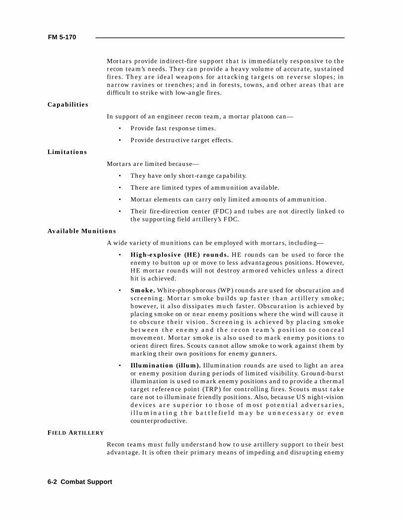
FM 5-170
Mortars provide indirect-fire support that is immediately responsive to therecon team’s needs. They can provide a heavy volume of accurate, sustainedfires. They are ideal weapons for attacking targets on reverse slopes; innarrow ravines or trenches; and in forests, towns, and other areas that aredifficult to strike with low-angle fires.
Capabilities
In support of an engineer recon team, a mortar platoon can—
• Provide fast response times.
• Provide destructive target effects.
Limitations
Mortars are limited because—
• They have only short-range capability.
• There are limited types of ammunition available.
• Mortar elements can carry only limited amounts of ammunition.
• Their fire-direction center (FDC) and tubes are not directly linked tothe supporting field artillery’s FDC.
Available Munitions
A wide variety of munitions can be employed with mortars, including—
• High-explosive (HE) rounds. HE rounds can be used to force theenemy to button up or move to less advantageous positions. However,HE mortar rounds will not destroy armored vehicles unless a directhit is achieved.
• Smoke. White-phosphorous (WP) rounds are used for obscuration andscreening. Mortar smoke builds up faster than artillery smoke;however, it also dissipates much faster. Obscuration is achieved byplacing smoke on or near enemy positions where the wind will cause itto obscure their vision. Screening is achieved by placing smokebetween the enemy and the recon team’s position to concealmovement. Mortar smoke is also used to mark enemy positions toorient direct fires. Scouts cannot allow smoke to work against them bymarking their own positions for enemy gunners.
• Illumination (illum). Illumination rounds are used to light an areaor enemy position during periods of limited visibility. Ground-burstillumination is used to mark enemy positions and to provide a thermaltarget reference point (TRP) for controlling fires. Scouts must takecare not to illuminate friendly positions. Also, because US night-visiondevices are superior to those of most potential adversaries,i l lumin at ing th e bat t le f ie ld may be unn ecessar y or ev encounterproductive.
FIELD ARTILLERY
Recon teams must fully understand how to use artillery support to their bestadvantage. It is often their primary means of impeding and disrupting enemy
6-2 Combat Support
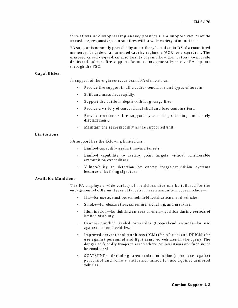
FM 5-170
formations and suppressing enemy positions. FA support can provideimmediate, responsive, accurate fires with a wide variety of munitions.
FA support is normally provided by an artillery battalion in DS of a committedmaneuver brigade or an armored cavalry regiment (ACR) or a squadron. Thearmored cavalry squadron also has its organic howitzer battery to providededicated indirect-fire support. Recon teams generally receive FA supportthrough the FSO.
Capabilities
In support of the engineer recon team, FA elements can—
• Provide fire support in all weather conditions and types of terrain.
• Shift and mass fires rapidly.
• Support the battle in depth with long-range fires.
• Provide a variety of conventional shell and fuze combinations.
• Provide continuous fire support by careful positioning and timelydisplacement.
• Maintain the same mobility as the supported unit.
Limitations
FA support has the following limitations:
• Limited capability against moving targets.
• Limited capability to destroy point targets without considerableammunition expenditure.
• Vulnerability to detection by enemy target-acquisition systemsbecause of its firing signature.
Available Munitions
The FA employs a wide variety of munitions that can be tailored for theengagement of different types of targets. These ammunition types include—
• HE—for use against personnel, field fortifications, and vehicles.
• Smoke—for obscuration, screening, signaling, and marking.
• Illumination—for lighting an area or enemy position during periods oflimited visibility.
• Cannon-launched guided projectiles (Copperhead rounds)—for useagainst armored vehicles.
• Improved conventional munitions (ICM) (for AP use) and DPICM (foruse against personnel and light armored vehicles in the open). Thedanger to friendly troops in areas where AP munitions are fired mustbe considered.
• SCATMINEs (including area-denial munitions)—for use againstpersonnel and remote antiarmor mines for use against armoredvehicles.
Combat Support 6-3
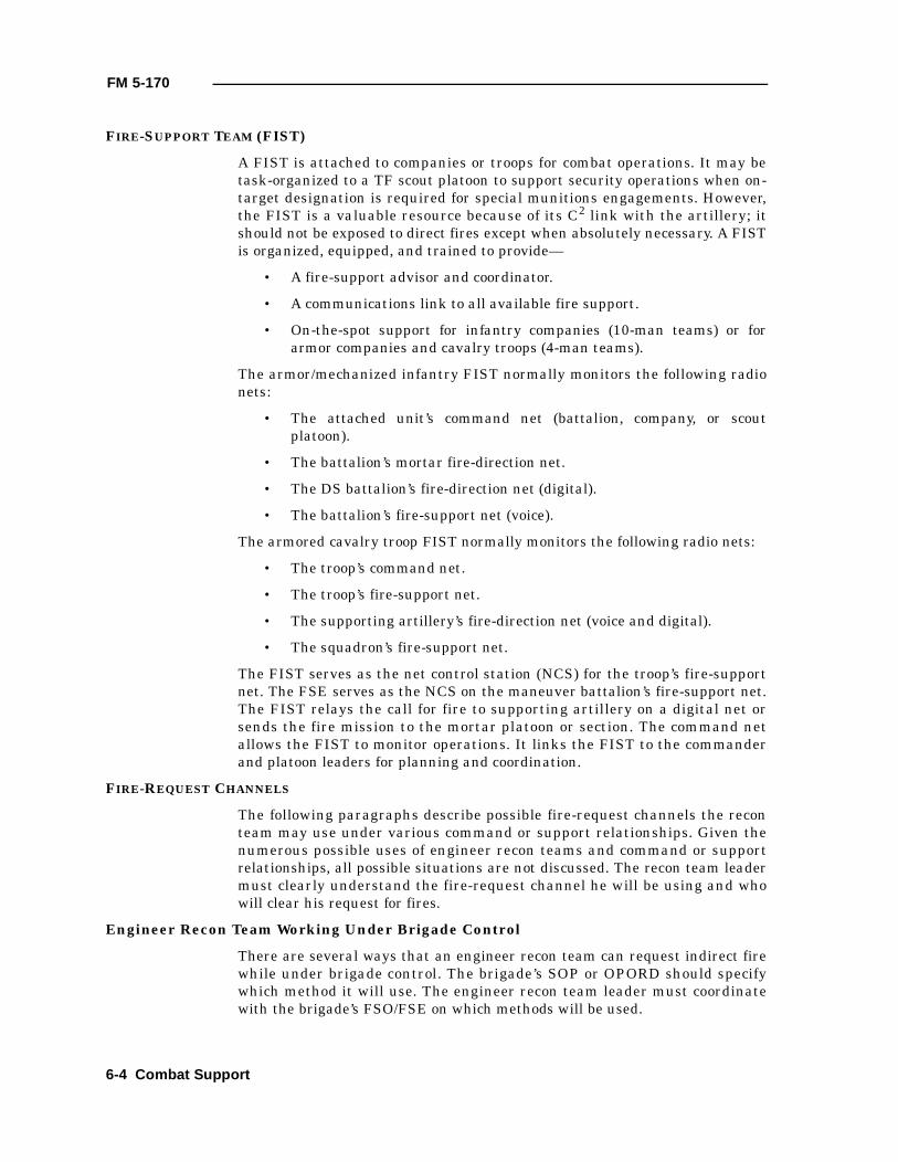
FM 5-170
FIRE-SUPPORT TEAM (FIST)
A FIST is attached to companies or troops for combat operations. It may betask-organized to a TF scout platoon to support security operations when on-target designation is required for special munitions engagements. However,the FIST is a valuable resource because of its C2 link with the artillery; itshould not be exposed to direct fires except when absolutely necessary. A FISTis organized, equipped, and trained to provide—
• A fire-support advisor and coordinator.
• A communications link to all available fire support.
• On-the-spot support for infantry companies (10-man teams) or forarmor companies and cavalry troops (4-man teams).
The armor/mechanized infantry FIST normally monitors the following radionets:
• The attached unit’s command net (battalion, company, or scoutplatoon).
• The battalion’s mortar fire-direction net.
• The DS battalion’s fire-direction net (digital).
• The battalion’s fire-support net (voice).
The armored cavalry troop FIST normally monitors the following radio nets:
• The troop’s command net.
• The troop’s fire-support net.
• The supporting artillery’s fire-direction net (voice and digital).
• The squadron’s fire-support net.
The FIST serves as the net control station (NCS) for the troop’s fire-supportnet. The FSE serves as the NCS on the maneuver battalion’s fire-support net.The FIST relays the call for fire to supporting artillery on a digital net orsends the fire mission to the mortar platoon or section. The command netallows the FIST to monitor operations. It links the FIST to the commanderand platoon leaders for planning and coordination.
FIRE-REQUEST CHANNELS
The following paragraphs describe possible fire-request channels the reconteam may use under various command or support relationships. Given thenumerous possible uses of engineer recon teams and command or supportrelationships, all possible situations are not discussed. The recon team leadermust clearly understand the fire-request channel he will be using and whowill clear his request for fires.
Engineer Recon Team Working Under Brigade Control
There are several ways that an engineer recon team can request indirect firewhile under brigade control. The brigade’s SOP or OPORD should specifywhich method it will use. The engineer recon team leader must coordinatewith the brigade’s FSO/FSE on which methods will be used.
6-4 Combat Support
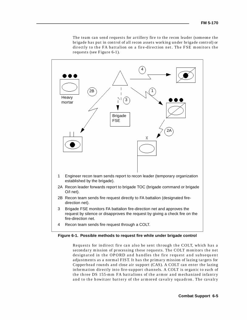
FM 5-170
The team can send requests for artillery fire to the recon leader (someone thebrigade has put in control of all recon assets working under brigade control) ordirectly to the FA battalion on a fire-direction net. The FSE monitors therequests (see Figure 6-1).
Requests for indirect fire can also be sent through the COLT, which has asecondary mission of processing these requests. The COLT monitors the netdesignated in the OPORD and handles the fire request and subsequentadjustments as a normal FIST. It has the primary mission of lazing targets forCopperhead rounds and close air support (CAS). A COLT can enter the lazinginformation directly into fire-support channels. A COLT is organic to each ofthe three DS 155-mm FA battalions of the armor and mechanized infantryand to the howitzer battery of the armored cavalry squadron. The cavalry
Figure 6-1. Possible methods to request fire while under brigade control
Heavymortar
BrigadeFSE
4
3
12B
2A
1 Engineer recon team sends report to recon leader (temporary organization established by the brigade).
2A Recon leader forwards report to brigade TOC (brigade command or brigade O/I net).
2B Recon team sends fire request directly to FA battalion (designated fire-direction net).
3 Brigade FSE monitors FA battalion fire-direction net and approves the request by silence or disapproves the request by giving a check fire on the fire-direction net.
4 Recon team sends fire request through a COLT.
Combat Support 6-5
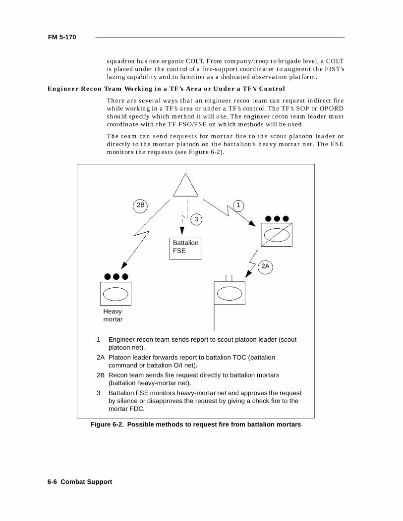
FM 5-170
squadron has one organic COLT. From company/troop to brigade level, a COLTis placed under the control of a fire-support coordinator to augment the FIST’slazing capability and to function as a dedicated observation platform.
Engineer Recon Team Working in a TF’s Area or Under a TF’s Control
There are several ways that an engineer recon team can request indirect firewhile working in a TF’s area or under a TF’s control. The TF’s SOP or OPORDshould specify which method it will use. The engineer recon team leader mustcoordinate with the TF FSO/FSE on which methods will be used.
The team can send requests for mortar fire to the scout platoon leader ordirectly to the mortar platoon on the battalion’s heavy mortar net. The FSEmonitors the requests (see Figure 6-2).
Figure 6-2. Possible methods to request fire from battalion mortars
Heavymortar
BattalionFSE
3
12B
2A
1 Engineer recon team sends report to scout platoon leader (scout platoon net).
2A Platoon leader forwards report to battalion TOC (battalion command or battalion O/I net).
2B Recon team sends fire request directly to battalion mortars (battalion heavy-mortar net).
3 Battalion FSE monitors heavy-mortar net and approves the request by silence or disapproves the request by giving a check fire to the mortar FDC.
6-6 Combat Support
FM 5-170
The team can send requests for artillery fire to the TF scout platoon leader ordirectly to the FA battalion on a fire-direction net. The FSE monitors therequests (see Figure 6-3).
Engineer Recon Team Working with a Cavalry Squadron or Under Troop Control
A recon team working under squadron control would request fire the sameway as if it were under brigade control (see Figure 6-1, page 6-5). However, ifthe recon team is placed under a troop’s control, the call for fire changesslightly. When working for or with an armored cavalry troop, requests for allindirect-fire support normally goes through the troop FIST on the troop’s fire-support net. The FIST selects the best available fire support to engage thetarget. If the FIST passes the fire mission to the troop mortar platoon, therecon team sends all adjustments of the fire mission directly to the mortar
Figure 6-3. Possible methods to request fire from FA battalion
BattalionFSE
3
12B
2A
1 Engineer recon team sends report to the scout platoon leader (scout platoon net).
2A Platoon leader forwards report to battalion TOC (battalion command or battalion O/I net).
2B Recon team sends fire request directly to FA battalion (designated fire-direction net).
3 Battalion FSE monitors FA battalion fire-direction net and approves the request by silence or disapproves the request by giving a check fire on the fire-direction net.
Combat Support 6-7
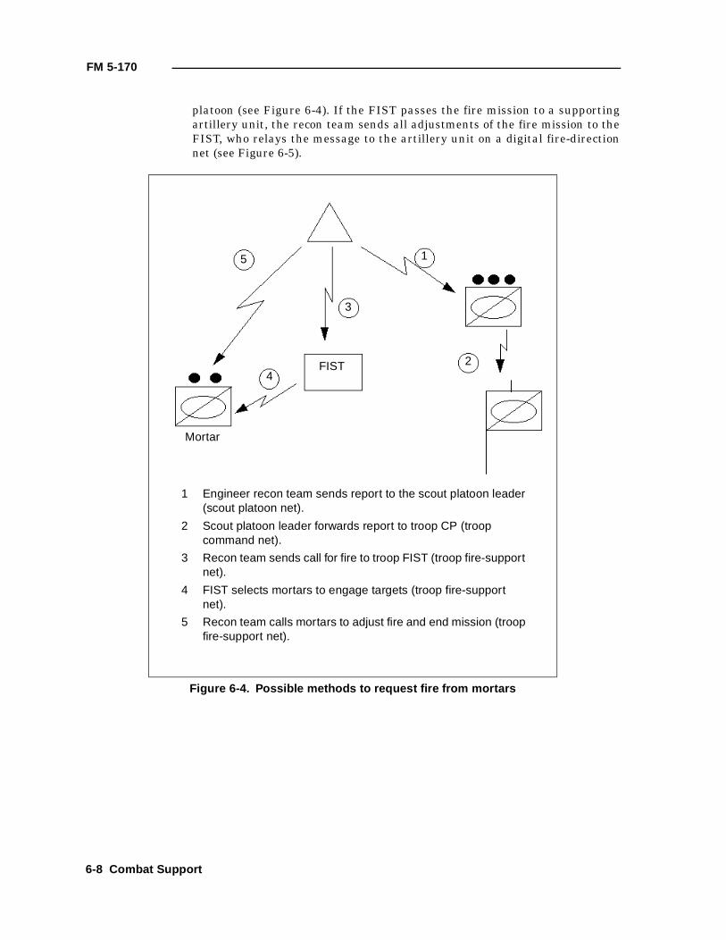
FM 5-170
platoon (see Figure 6-4). If the FIST passes the fire mission to a supportingartillery unit, the recon team sends all adjustments of the fire mission to theFIST, who relays the message to the artillery unit on a digital fire-directionnet (see Figure 6-5).
Figure 6-4. Possible methods to request fire from mortars
Mortar
FIST
3
15
2
1 Engineer recon team sends report to the scout platoon leader (scout platoon net).
2 Scout platoon leader forwards report to troop CP (troop command net).
3 Recon team sends call for fire to troop FIST (troop fire-support net).
4 FIST selects mortars to engage targets (troop fire-support net).
5 Recon team calls mortars to adjust fire and end mission (troop fire-support net).
4
6-8 Combat Support
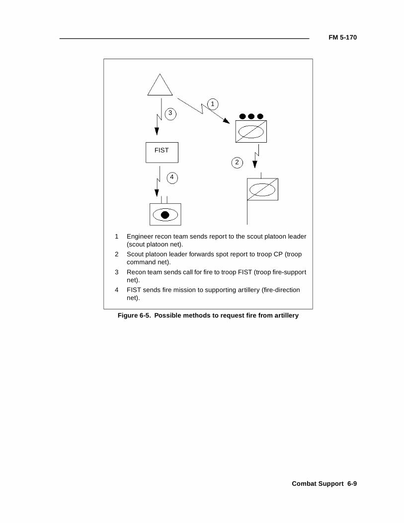
FM 5-170
Figure 6-5. Possible methods to request fire from artillery
FIST
31
2
1 Engineer recon team sends report to the scout platoon leader (scout platoon net).
2 Scout platoon leader forwards spot report to troop CP (troop command net).
3 Recon team sends call for fire to troop FIST (troop fire-support net).
4 FIST sends fire mission to supporting artillery (fire-direction net).
4
Combat Support 6-9
FM 5-170
AIR DEFENSE
Air-defense assets are scarce; maneuver units cannot plan on always receivingdedicated air-defense protection. Consequently, recon teams must be able toprotect themselves from enemy air attacks during all combat operations. Air-defense measures include taking actions to avoid enemy air attack or to limitthe damage if attacked and, if necessary, fighting back.
PASSIVE AIR DEFENSE
Passive air defense is the team’s first line of defense against enemy air attack.It includes all measures—other than active defense—taken to minimize theeffects of hostile air action. There are two types of passive air defense: attackavoidance and damage-limiting measures.
Attack Avoidance
If an enemy pilot cannot find you, he cannot attack you. Recon teams useconcealment, camouflage, deception, and any other necessary action toprevent the enemy from seeing them.
Team positions must provide effective concealment. When concealment is notavailable, vehicles must be camouflaged to blend into the naturalsurroundings. Track marks leading into the position must be obliterated. Allshiny objects that reflect light and attract attention must be covered.
Damage-Limiting Measures
Dispersion is one of the most effective ways to reduce the effects of enemy airattack. When the team is on the move and air guards identify an enemy airattack, vehicles disperse quickly, move to a concealed position if possible, andstop (a stationary vehicle is more difficult to see than a moving one).
Another damage-limiting measure is using natural or man-made cover toreduce the effects of enemy munitions. Folds in the earth, depressions,buildings, and sandbagged positions can provide this protection.
ACTIVE AIR DEFENSE
Although passive measures are the first line of defense against an air attack,a recon team must be prepared to engage enemy aircraft. The decision to fightback against an air threat is based on the situation and the capabilities of theorganic weapon systems. All team members must understand the weapon-control status. They can defend against direct attacks but cannot engageaircraft that are not attacking them unless the weapon-control status allowsit.
Engineer scouts have several weapon systems (machine guns and small arms)that can be used against aircraft. Engaging aircraft with volume fire is thekey to effectively using small-arms and machine-gun fires against an airattack. These fires must be coordinated to be effective. Delivered on the teamleader’s command, they are directed at an aim point in front of the target;gunners do not attempt to track the target. The rules for selecting the aimpoint are listed in Table 6-2. They are simple and logical; they must be learnedand retained by everyone in the team.
6-10 Combat Support
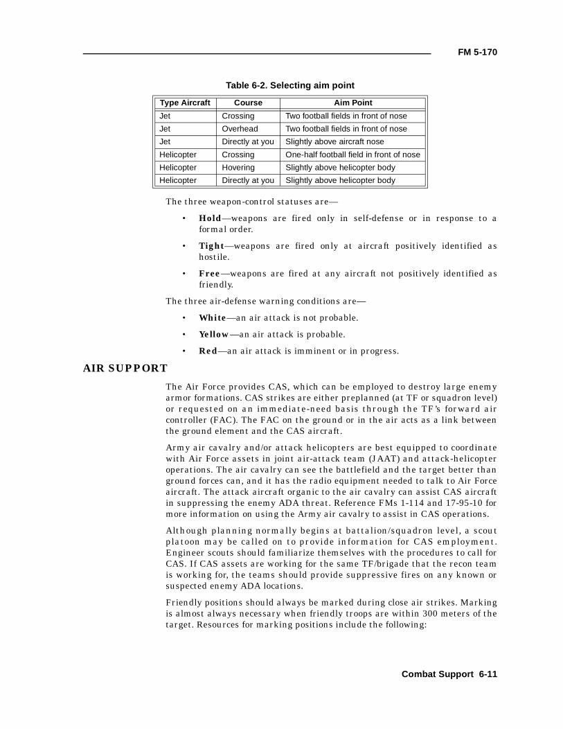
FM 5-170
The three weapon-control statuses are—
• Hold—weapons are fired only in self-defense or in response to aformal order.
• Tight—weapons are fired only at aircraft positively identified ashostile.
• Free—weapons are fired at any aircraft not positively identified asfriendly.
The three air-defense warning conditions are—
• White—an air attack is not probable.
• Yellow—an air attack is probable.
• Red—an air attack is imminent or in progress.
AIR SUPPORT
The Air Force provides CAS, which can be employed to destroy large enemyarmor formations. CAS strikes are either preplanned (at TF or squadron level)or requested on an immediate-need basis through the TF’s forward aircontroller (FAC). The FAC on the ground or in the air acts as a link betweenthe ground element and the CAS aircraft.
Army air cavalry and/or attack helicopters are best equipped to coordinatewith Air Force assets in joint air-attack team (JAAT) and attack-helicopteroperations. The air cavalry can see the battlefield and the target better thanground forces can, and it has the radio equipment needed to talk to Air Forceaircraft. The attack aircraft organic to the air cavalry can assist CAS aircraftin suppressing the enemy ADA threat. Reference FMs 1-114 and 17-95-10 formore information on using the Army air cavalry to assist in CAS operations.
Although planning normally begins at battalion/squadron level, a scoutplatoon may be called on to provide information for CAS employment.Engineer scouts should familiarize themselves with the procedures to call forCAS. If CAS assets are working for the same TF/brigade that the recon teamis working for, the teams should provide suppressive fires on any known orsuspected enemy ADA locations.
Friendly positions should always be marked during close air strikes. Markingis almost always necessary when friendly troops are within 300 meters of thetarget. Resources for marking positions include the following:
Table 6-2. Selecting aim point
Type Aircraft Course Aim Point
Jet Crossing Two football fields in front of nose
Jet Overhead Two football fields in front of nose
Jet Directly at you Slightly above aircraft nose
Helicopter Crossing One-half football field in front of nose
Helicopter Hovering Slightly above helicopter body
Helicopter Directly at you Slightly above helicopter body
Combat Support 6-11
FM 5-170
• Smoke. The smoke grenade is the most commonly used marker, but ithas limitations. Wind may cause smoke to drift above trees, and somecolors can blend with the background. Violet or white smoke shows upwell with most backgrounds.
• Flares. Flares are good for attracting attention at night; they aresometimes effective during the day.
• Mirrors. Signal mirrors are probably the best ground-to-air devicesfor attracting attention. If the sun is shining and the operator isskillful, pilots can see a mirror flash miles away. VS-17 signal panelsare also good visual references for pilots.
• Lights. Pocket-sized, battery-powered strobe lights produce brilliantwhite or blue flashes at about 1 1/2-second intervals. The flash isvisible at night for 1 to 3 miles. Vehicle lights, such as an unshieldedred taillight, are visible to a pilot for several miles at night. Chemicalglow lights can be used to mark friendly positions. Another techniquethat can be used at night is to tie an infrared or green chemical lighton a 10-foot string. When aircraft are in the area, a team member canswing the rope in a circular motion to mark the location.
Evolving technology provides a more accurate, secure, and effective means ofsupplementing or replacing traditional methods. Using a GPS will pinpoint aposition to avoid fratricide during CAS operations.
GROUND SURVEILLANCE RADAR
A GSR team can augment a recon team’s surveillance capability by detectingtargets and providing accurate range and azimuth readings to enemylocations and obstacles during limited-visibility conditions. A team consists ofthree soldiers, one AN/PPS-5 radar unit, and an APC or a HMMWV.
For combat operations, GSR teams are usually attached to TFs andsquadrons. The teams may be attached or under OPCON to companies/troopsor recon elements for specific missions. When GSR is attached or underOPCON to a recon team, the team leader must plan its employment.
CAPABILITIES AND LIMITATIONS
GSR teams provide mobile, all-weather battlefield surveillance. Whenemployed in pairs, they can provide observation from a given vantage point 24hours a day.
The AN/PPS-5 has a line-of-sight range of 10,000 meters against vehicles and6,000 meters against personnel. It can detect targets through lightcamouflage, smoke, haze, light snow and rain, and darkness. Foliage, heavyrain, and snow seriously restrict its radar-detection capability.
GSR is designed to detect targets moving against a background. It is generallyineffective against an air target unless the aircraft is flying close to theground. It is vulnerable to enemy direction-finding and jamming equipment.The GSR team is normally equipped with a single radio. If forward with therecon team, the GSR team should send all reports to the recon team.
6-12 Combat Support
FM 5-170
EMPLOYMENT
A GSR team should be assigned a specific sector of surveillance and frequencyof coverage. However, GSR cannot be used for continuous surveillance becausethe enemy can detect radar signals. The tasks assigned to GSR teams in theirsurveillance mission may include the following:
• Searching avenues of approach or possible enemy positions on ascheduled or random basis to determine the location, size, andcomposition of enemy forces and the nature of their activity.
• Monitoring point targets such as bridges, defiles, or road junctions andreporting quantity, type, and direction of enemy vehicles andpersonnel moving through the target area.
• Extending the recon team’s observation capabilities by enabling themto survey distant points and areas of special interest.
GSR must be positioned in an area that is free of ground clutter (such as trees,thick vegetation, and buildings) and that affords long-range observation and awide field of view. Normally, the team will be assigned a general area, and theGSR team leader will select the specific position. To avoid enemy suppressivefires, the team should be prepared for rapid displacement by selecting severalalternate positions ahead of time.
During a recon, GSR is best employed to the recon team’s flanks or oriented onpotential enemy locations. Since recon is a moving operation, the GSR teamswill have to move as necessary to support the team.
CHEMICAL
When in a nuclear, biological, and chemical (NBC) environment, NBC reconelements can augment an engineer recon team’s operational capability byproviding NBC detection, warning, and sampling. The Fox (or its replacement)is a high-speed, high-mobility, wheeled, armored carrier capable of performingNBC recon on primary, secondary, or cross-country routes throughout thebattlefield. The basic item or equipment to perform NBC recon is the M93-series NBC Reconnaissance System (NBCRS) or the Fox vehicle. A teamconsists of one Fox vehicle with its crew; two Fox vehicles and their crewscompose a squad. NBC recon units are organic to the heavy division, the corps,the ACR, and the light ACR.
Depending on the other assigned priorities, an NBC recon team may beattached or under OPCON to an engineer battalion or a TF for specificmissions. The NBC recon team can significantly enhance the engineer reconteams by being integrated into the overall R&S plan for monitoring NAIs.
CAPABILITIES AND LIMITATIONS
An NBC recon team assists an engineer recon team and in turn provides themaneuver force commander with information to maintain momentum andflexibility and avoid contamination.
The team has the capability to—
• Conduct an NBC recon and survey while on the move.
Combat Support 6-13
FM 5-170
• Conduct an NBC recon mission without exiting the vehicle.
• Provide location data to better delineate contamination.
• Use a marking system that allows contamination to be markedwithout exposing the crew.
• Cover large areas due to its mobility.
• Communicate digitally.
The team is limited because it—
• Is not heavily armored.
• Cannot conduct standoff chemical surveillance with the M21 Rascalon the move.
• Does not have biological detection/identification capability.
The NBC recon team is equipped with the AN/VRC-89 and AN/VRC-90 radiosand can communicate with both the engineer recon team and the engineerbattalion or TF.
EMPLOYMENT
In an NBC environment, there are relatively sudden and drastic changes inthe tactical situation, including—
• Dispersion.
• Mobility.
• Decentralization of control.
• Rapid exploitation.
• Reduction of reaction time.
In this type of environment, route recon assumes even greater importancethan in conventional operations. Not only will more routes be required tosupport operations, but the engineer recon team must be alerted towidespread areas of contamination created by weapons of mass destruction.NBC recon elements/teams will provide an effective means of alertingengineer recon teams to these NBC hazards.
NBC recon performs five critical tasks on the battlefield: detect, identify,mark, report, and sample. Detecting NBC hazards early will permit timelywarning of engineer recon teams preparing for or actually performing theircritical missions. Knowing that NBC hazards are present in a planned AO willenable engineer recon personnel to avoid the area, take the appropriateprotection level, or treat casualties that may result, if required.
The tasks assigned to the NBC recon team in its support role of performingroute, zone, area, and point recon include the following:
• NBC route recon (a directed effort to obtain information on a specificroute). The team—
— Recons the assigned route and determines the location of anycontamination.
6-14 Combat Support
FM 5-170
— Locates and marks bypassed routes if contamination isencountered.
— Reports and marks all NBC hazards along the route.
• NBC zone recon (a directed effort to obtain detailed information aboutNBC hazards within a specified zone). The team—
— Recons all terrain within the zone for contamination.
— Locates all previously reported NBC attack areas and determinesif a hazard is still present.
— Locates all possible contamination within the zone.
— Checks all water sources for contamination.
— Marks contaminated areas.
• NBC area recon (a directed effort to obtain detailed informationconcerning a specific area). The team—
— Conducts a survey to define the extent of contamination.
— Locates and marks clear bypass routes.
• NBC point recon (a directed effort to obtain detailed informationconcerning a specific terrain feature). The team—
— Conducts a survey to define the extent of contamination.
— Collects samples.
— Locates and marks clear bypass routes.
Chemical mechanized smoke platoons also have the capability to augmentengineer recon-team operations when the latter team in the defense isemployed to—
• Screen if the engineer battalion is required to occupy a battle positionas an engineer TF.
• Overwatch a friendly emplaced scatterable minefield.
• Overwatch NAIs where enemy scatterable minefields are known.
The smoke platoon will probably be OPCON to the engineer battalion forspecific missions.
Combat Support 6-15

FM 5-170
6-16 Combat Support
Chapter 7
Combat Service Support
This chapter primarily deals with CSS to engineer recon teams conductingobstacle recon. Recon teams conducting more traditional missions such aszone, route, area, or technical recons will conduct CSS operations similarto those discussed in FMs 5-71-2 and 5-71-3.
CSS elements arm, fuel, fix, feed, clothe, and provide transportation andpersonnel for the recon team. The recon team leader is responsible forsupervising CSS within the team. The assistant team leader is the team’sCSS operator, as the first sergeant (1SG) is for a company. The assistantteam leader advises the team leader of logistical requirements whilepreparing for combat operations. He also keeps the team leader informedof the team’s logistical status.
ORGANIZATION
A recon team does not have organic CSS assets. The assistant team leader isprimarily responsible for determining the team’s maintenance, supply, andpersonnel statuses. He coordinates directly with the 1SG for all CSS.
An engineer recon team presents complex logistical problems for the battalionstaff. As explained in Chapters 3 and 4, the team normally operates to thefront of the brigade/battalion TF. The team will probably move earlier andstay away longer than any other battalion element. It can be resupplied in oneof several ways.
A maintenance team and/or logistics package (LOGPAC) can be dedicated tothe engineer recon team. The maintenance team responds to the needs of therecon team and is brought forward by the company’s 1SG or anotherresponsible individual. The support package is tailored specifically to theengineer recon team’s requirements and is small and flexible. The LOGPAClinks up with the team at a specifically designated logistics release point(LRP) as far forward as possible. The assistant team leader is then responsiblefor distributing supplies to the recon team. He may distribute supplies byhimself or be assisted by the individual who brought the LOGPAC forward,which is significantly faster. This method is best for the recon team, butdifficult for the battalion because of its limited CSS resources.
The engineer recon team can also use the nearest company team's CSS assetsfor its resupply and maintenance. If this technique is used, the headquartersand headquarters company (HHC) commander/S4 and the engineer reconteam leader should coordinate with the company team 1SG for support. TheHHC commander and the battalion S4 should ensure that the suppliesdedicated for the resupply of the engineer recon team are forwarded with thecompany team's regular LOGPAC. If possible, engineer recon team supplies
Combat Service Support 7-1
FM 5-170
pushed forward with the company team LOGPAC should be separated toensure rapid resupply of the engineer scouts. In any case, the company teamcommander must realize the importance of refueling and rearming theengineer recon team.
Whatever support the engineer scout recon team receives must be keyed to afast transfer of supplies. The recon team must be able to pull in, resupply, andleave as quickly as possible. The actual time that the recon team needs toresupply does not often coincide with standard LOGPAC times for the rest ofthe battalion. The S4, the support platoon leader, the engineer recon teamleader, and any other key leaders must anticipate events to coordinate for thebest resupply time.
SUPPLY OPERATIONS
Each team has a large amount of equipment and requires frequent resupply toaccomplish its mission. Periodic checks are required by all leaders to makesure that the team's equipment (especially high-use items) is accounted forand ready to use. Leaders must anticipate expenditures and request suppliesbefore an operation.
BASIC LOAD
For classes of supply other than ammunition, basic loads are supplies kept byunits for use in combat. The quantity of each item of supply in a basic load isbased on the number of days the team may have to sustain itself withoutresupply. For ammunition, the basic load is the quantity required to be onhand to meet combat needs until resupply can be accomplished. The basicammunition load is specified by the commander. The basic load of a reconteam will probably not be the same as the rest of the unit because of theamount of time the recon team may be expected to operate away from theengineer battalion. This basic load must be well planned.
CLASSES OF SUPPLY
The following paragraphs examine each class of supply and discuss importantconsiderations as they apply to the recon team:
Class I
This class includes subsistence items and gratuitous-issue health and welfareitems. Meal, ready-to-eat (MRE) rations are stocked on each vehicle (usually a3- to 5-day supply). A-rations are brought forward when possible tosupplement MREs.
Potable water should be replenished daily, either by refilling from the watertrailer or by rotating 5-gallon cans during LOGPAC. Each combat vehicleshould maintain a minimum of 5 gallons of potable water per soldier, moreduring operations in arid climates or in mission-oriented protective posture(MOPP) gear.
All meals should be eaten in shifts. The team leader must not only make surethat the team is fed, but also that the team eats nutritious meals to maintainthe energy levels required in combat. During continuous or cold-weatheroperations, soldiers should eat more than three meals per day. The extraallowance must be planned for.
7-2 Combat Service Support
FM 5-170
Class II
This class includes items of equipment (other than principal items) that areprescribed in authorization and allowance tables. Individual tools and toolsets, individual equipment and clothing items, chemical lights, batteries,engineer tape, tentage, and housekeeping supplies are requested through thesupply sergeant.
Class III and Class V
Class III comprises all types of POL products. Class V is ammunition, toinclude small arms, mines, and demolitions. For optimum security, refuelingand rearming should occur simultaneously under the cover of darkness. Thisresupply usually occurs daily or at the conclusion of major operations. The twotechniques of refueling and rearming—tailgate and service station—arecovered later in this section.
The team leader must control the redistribution of supplies when fuel andammunition cannot be delivered or when only limited supplies are available.He continually monitors the section's supply status through logistical reports.He notifies the chain of command when a specific vehicle or the team as awhole is critically short of these major classes of supply. The team leadershould ensure that ammunition is equally distributed throughout the teambefore any tactical operation and during consolidation on an objective.
When planning for refueling, the team leader should keep the range andcapacity of his vehicles and the requirements of future operations in mind; theamount of fuel required determines how much time it will take to refuel. Theteam leader must realize that a vehicle’s cruising range and estimated fuelconsumption are only approximations, subject to the effects of weather,terrain, and other factors. The team must refuel vehicles whenever thetactical situation permits. When time is limited, the assistant team leadermust choose between refueling vehicles that need the most fuel first or givinglimited amounts to each. Each vehicle crew needs to maintain a stock of ClassIII-P materials (such as oil, grease, and hydraulic fluid), replenishing thesePOL products every time refueling takes place.
Class IV
This class includes construction and barrier materials. Barrier materials suchas lumber, sandbags, concertina or barbed wire, and pickets are used by theteam to construct OPs and obstacles and to improve fighting positions. Thesematerials are requested through the company or directly from the S4.
Class VI
This class covers personal demand items. Tobacco products, candy, and toiletryarticles are normally sold through the exchange system during peacetime orfor units not in a combat environment. In a combat environment, these itemsare sent with Class I as sundry packs.
Class VII
This class includes major end items. These are major pieces of equipment,assembled and ready for intended use, such as combat vehicles, missilelaunchers, artillery pieces, and major weapon systems. Major end items that
Combat Service Support 7-3
FM 5-170
are destroyed are reported immediately by means of logistical reports. Theywill be replaced by the parent unit as they are reported.
Class VIII
This class includes medical supplies that are provided through the battalionmedical section and ordered through the battalion. These supplies includeindividual medical supplies such as first-aid dressings, refills for first-aid kits,water-purification tablets, and foot powder.
Class IX
This class comprises repair parts. These basic-load supplies are part of thecombat prescribed load list (PLL). PLL items carried by the team usuallyinclude spare tires, assorted bolts, machine-gun parts, and light bulbs. ClassIX supplies are requisitioned through the battalion’s maintenance section.
TECHNIQUES OF RESUPPLY
The tactical situation and type/size of the engineer recon element will dictatewhich technique of resupply to use: tailgate, service station, a variation of onetype, or a combination of both types. The situation will also dictate when toresupply. Generally, a recon team avoids resupply during recon operations;resupply should be done during mission transition.
In the tailgate technique, fuel and ammunition are brought to the engineerrecon team by the assistant team leader or another responsible individual whois assisting him (see Figure 7-1). This method is used when routes leading tovehicle positions are available and the unit is not under direct enemyobservation and fire. This technique is time-consuming, but useful in missionswhen the recon team is not moving and stealth is more easily maintained. Ifnecessary, hand carry supplies to vehicle positions, further minimizingsignatures.
In the service-station technique, vehicles move to a centrally located rearmand refuel point, either by vehicles or as an entire team (see Figure 7-2).Service-station resupply is inherently faster than the tailgate method;however, because vehicles must move and concentrate, it can create securityproblems.
The assistant team leader can vary the specifics of the two basic techniques, orhe can use them in combination. For example, he may use the tailgate methodfor his most forward OPs and the service-station method for his OPs further tothe rear (see Figure 7-3, page 7-6).
MAINTENANCE OPERATIONS
Proper maintenance keeps equipment and materiel in serviceable condition. Itincludes preventive maintenance checks and services (PMCS) as well as thefunctions of inspecting, testing, servicing, repairing, requisitioning,recovering, and evacuating equipment and materiel whenever necessary.
Maintenance tasks are divided into unit (operator and organizational), DS,GS, and depot levels. The team leader is concerned primarily with unitmaintenance and repair of equipment in DS maintenance.
7-4 Combat Service Support
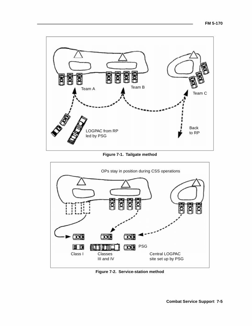
FM 5-170
Figure 7-1. Tailgate method
Figure 7-2. Service-station method
Team A Team B
Team C
LOGPAC from RP led by PSG
Backto RP
Class I Classes III and IV
PSG
Central LOGPAC site set up by PSG
OPs stay in position during CSS operations
Combat Service Support 7-5
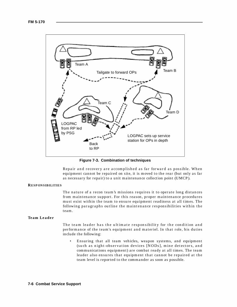
FM 5-170
Repair and recovery are accomplished as far forward as possible. Whenequipment cannot be repaired on site, it is moved to the rear (but only as faras necessary for repair) to a unit maintenance collection point (UMCP).
RESPONSIBILITIES
The nature of a recon team’s missions requires it to operate long distancesfrom maintenance support. For this reason, proper maintenance proceduresmust exist within the team to ensure equipment readiness at all times. Thefollowing paragraphs outline the maintenance responsibilities within theteam.
Team Leader
The team leader has the ultimate responsibility for the condition andperformance of the team's equipment and materiel. In that role, his dutiesinclude the following:
• Ensuring that all team vehicles, weapon systems, and equipment(such as night-observation devices [NODs], mine detectors, andcommunications equipment) are combat ready at all times. The teamleader also ensures that equipment that cannot be repaired at theteam level is reported to the commander as soon as possible.
Figure 7-3. Combination of techniques
Team A
Team B
Team C
LOGPAC from RP led by PSG
Backto RP
Team D
LOGPAC sets up service station for OPs in depth
Tailgate to forward OPs
7-6 Combat Service Support
FM 5-170
• Knowing the present status of equipment, to include documentnumbers, job order numbers, and the maintenance stage of hisvehicles. The team leader keeps his company commander informed ofthe current maintenance status.
• Coordinating with the maintenance officer in planning, directing, andsupervising the team’s unit maintenance.
• Developing and supervising an ongoing maintenance trainingprogram.
• Ensuring that crews have the appropriate TMs and are trained andsupervised to complete the required level of maintenance properly.
• Ensuring that unit-level PMCS are performed on all assignedequipment according to the appropriate operator's manuals.
• Ensuring that operators and assistant operators are trained andlicensed to operate team vehicles and equipment in all weatherconditions.
• Planning and rehearsing a maintenance evacuation plan for everymission.
• Supervising and accounting for section personnel during maintenanceperiods.
• Ensuring that repair parts are used or stored in a timely fashion asthey are received.
Assistant Team Leader
The assistant team leader is the team's first-line maintenance supervisor. Inlarge part, the team's maintenance status, and thus its combat readiness,depends on its commitment to proper maintenance procedures. The assistantteam leader’s duties in this area include the following:
• Ensuring that DA Forms 2404 and 2408-14 are filled out and updatedaccording to DA Pamphlet (Pam) 738-750.
• Ensuring that the crew is properly trained in PMCS procedures andthat PMCS are performed on the vehicle according to the appropriateTMs.
• Ensuring that, as a minimum, the assigned vehicle operator isproperly trained and licensed. In preparing for continuous operations,the vehicle commander must ensure that all crew members aretraining and licensed as drivers.
• Collecting and consolidating the section's maintenance status in thefield and sending the appropriate reports to maintenance personnel.
• Ensuring that vehicles are always topped off with fuel in garrison andthat they receive fuel in the field.
• Ordering parts for the vehicle.
• Ensuring that repair parts are installed upon receipt or are stored inauthorized locations.
Combat Service Support 7-7
FM 5-170
• Ensuring that all tools and basic-issue items are properly marked,stored, maintained, and accounted for.
• Updating the vehicle’s status constantly.
Unit Maintenance (Operator Level)
Operator maintenance includes proper care, use, and maintenance of assignedvehicles and crew equipment such as weapons, NBC equipment, and NVDs.The driver and other crew members perform daily services on the vehicles andequipment, to include inspecting, servicing, tightening, performing minorlubrication, cleaning, preserving, and adjusting. The crew is required to recordthe checks and services, as well as all equipment faults that they cannotimmediately correct, on DA Form 2404. These reports are the primary meansof reporting equipment faults through the assistant team leader to the teamleader, and ultimately to organizational maintenance personnel.
Checks and services are prescribed for the automotive system and weaponsystems. They are divided into three groups:
• Before-operation checks.
• During-operation checks.
• After-operation checks.
These services are explained in every operator's manual and should beconducted as stated in the manual. Although operators must learn to operateequipment without referring to the manual, maintenance must be performedusing the appropriate TM, not from memory.
EVACUATION
Evacuation is necessary when a vehicle is damaged and cannot be repairedon-site within two hours or when it is the only means available to preventcapture or destruction by the enemy.
When a vehicle needs to be evacuated, the team leader reports its exactlocation, the vehicle type, and the extent of damage, if known, on theappropriate net to personnel designated in the unit’s SOP or OPORD. Twosoldiers should remain with the vehicle to assist in evacuation and repair,provide security, and deliver the repaired vehicle back to the team as soon aspossible. A recovery vehicle from the company, battalion, or TF maintenanceteam will evacuate the damaged vehicle. It is vital that the damaged vehiclebe placed in a covered position that allows the recovery vehicle to reach itwithout exposing the recovery crew to enemy fire.
If a recovery vehicle is not available or if time is critical, other team vehicles(if available) can evacuate the damaged vehicle for short distances. Thedecision to do this rests with the team leader. Procedures for towing arecontained in the operator's manual. If the damaged vehicle will be lost for anextended period, the team can replace other vehicles' damaged equipment(such as weapons and radios) with properly functioning items from thedamaged vehicle. The damaged equipment can then be repaired or replacedwhile the vehicle is being repaired. Self-evacuation by the team is a last resortthat should be considered only to avoid losing the damaged vehicle to theenemy.
7-8 Combat Service Support
FM 5-170
DESTRUCTION
When evacuation of damaged or inoperable equipment is impossible, it mustbe destroyed. Team leaders must make sure crews are trained to destroy thevehicle rather than allow it to fall into enemy hands. Instructions fordestroying each item of equipment are included in the operator' s manual.
The team leader should get the commander's authorization before destroyingany equipment. However, when communications fail, the team leader mustuse his judgment to decide whether or not evacuation is possible. Everyreasonable effort must be made to evacuate secure equipment, classifiedmaterials, and all weapons.
MEDICAL TREATMENT AND EVACUATION
Leaders must emphasize high standards of health and hygiene. Soldiers mustshave daily (so that their protective masks will seal) and bathe and changeclothes regularly to prevent disease. Each soldier should carry shavingequipment, soap, a towel, and a change of clothing in a waterproof bag insidehis pack.
During cold weather, soldiers must check their hands and feet regularly toprevent frostbite, trench foot, or immersion foot. They must also learn that theeffects of windchill on exposed skin are equal to those of temperatures muchlower than the thermometer shows. A moving vehicle will cause a windchilleffect even if the air is calm.
WOUNDED SOLDIERS
Battlefield positioning and dispersion make the treatment and evacuation ofwounded personnel two of the most difficult tasks that an engineer recon teammust execute. To ensure successful handling of wounded engineers, brigades,battalions, and TFs must specifically allocate CSS assets to the engineer reconteam to assist in evacuation. In addition, operational planning or SOPs mustcover evacuation procedures in detail.
In the engineer recon team, it is the team leader’s responsibility to ensure thatwounded team members receive immediate first aid and that the commanderis notified of all casualties. Using engineer scouts who are trained as combatlifesavers is critical. As a minimum, one member of each engineer recon teammust be trained as a combat lifesaver. If wounded team members requireevacuation, the team leader can do one of the following:
• Coordinate evacuation with the closest troop, scout platoon, orcompany team for ground evacuation.
• Request that the brigade/battalion TF task-organize a dedicatedambulance to the team for operations forward of the larger element. Inthe case of the HMMWV section, the ambulance should be a HMMWVvariant located (for security) with the nearest company team.
• Conduct self-evacuation with organic team assets.
• Coordinate for aerial evacuation through the battalion TF.
Aerial evacuation, if it is available, is preferred because of its speed. Theengineer scouts coordinate with their higher command and then switch to the
Combat Service Support 7-9
FM 5-170
designated frequency to coordinate directly with the medical-evacuation(MEDEVAC) aircraft. They must pick a relatively flat, open, and covered andconcealed position for the aircraft's LZ. The location should be given to theaircraft by radio and marked with colored smoke as the aircraft approachesthe area. The engineer recon team provides local security of the LZ until theevacuation is complete.
Regardless of the method of evacuation, the team leader and the assistantteam leader must have the necessary CSS graphics available, to includecasualty collection points. Evacuation procedures must be part of the sectionplan and should be rehearsed as part of mission preparation.
A wounded team member’s individual weapon becomes the responsibility ofthe assistant team leader. Personal effects, weapons, and equipment areturned in to the company supply sergeant at the earliest opportunity. Theteam member’s protective mask stays with him at all times. All sensitiveitems, such as maps, overlays, and SOPs, should also remain with the team.
SOLDIERS KILLED IN ACTION
The remains of personnel killed in action (KIA) will be placed in a body bag orsleeping bag or rolled in a poncho and evacuated by the team. The commanderwill designate a location for collection of KIA soldiers. If (as a last resort) thebody must be left on the battlefield, the name, exact location, andcircumstances are reported through channels with the appropriate SOPreport. The lower dog tag is removed for turn-in to the team leader. Thepersonal effects of a KIA soldier remain with the body. The KIA soldier'sweapon, equipment, and issue items become the responsibility of the assistantteam leader until they can be turned over to the supply sergeant or 1SG.
The bodies of KIA soldiers should not be placed on the same vehicle aswounded soldiers. If this rule cannot be adhered to, dead and woundedpersonnel may be carried on board a vehicle to its next stop. In an attack, thenext stop may be the objective; in the defense, it may be the next BP. Teamsmust be prepared to give first aid and to continue the mission with a limitedteam without stopping.
PRISONERS
Enemy prisoners of war (EPWs) are excellent sources of combat intelligenceinformation; they must be processed and evacuated to the rear quickly. Ifenemy soldiers want to surrender, it is a team's moral and legal responsibilityto take them into custody and safeguard them until they can be evacuated.
The team leader directs team members to take the EPWs to a designated area.The prisoners are then evacuated to the rear for interrogation.
If an EPW is wounded and cannot be evacuated through medical channels, thenearest company XO or 1SG is notified. The EPW will be escorted to thecompany trains, or the 1SG will come forward with guards to evacuate him.
PRISONERS OF WAR
The basic principles for handling EPWs are covered by the five S and one Tprocedures: search, segregate, silence, speed, safeguard, and tag.
7-10 Combat Service Support
FM 5-170
• Search. Remove all weapons and documents. Return to the EPWthose personal items of no military value. The EPW keeps his helmet,protective mask, and gear to protect him from immediate dangers ofthe battle area.
• Segregate. Break the chain of command; separate EPWs by rank,sex, and other suitable categories. Keep the staunch fighters awayfrom those who willingly surrender.
• Silence. Prevent EPWs from giving orders, planning escapes, anddeveloping false cover stories.
• Speed. Speed EPWs to the rear to remove them from the battle areaand to obtain and use their information.
• Safeguard. Prevent EPWs from escaping. Protect all EPWs fromviolence, insults, curiosity, and reprisals of any kind.
• Tag. Tag EPWs and documents or special equipment.
Never approach an enemy soldier. He may have a weapon hidden nearby, or hemay be booby trapped. Gesture for him to come forward until it is clear that heis honestly surrendering and not trying to lure friendly troops into anambush. Use a thermal sight to locate possible ambushes. When searching theEPW, always have another friendly soldier cover him with a weapon. Do notget between the EPW and the soldier covering him.
The rights of EPWs have been established by international law, and the UShas agreed to obey these laws. Once an enemy soldier shows he wants tosurrender, he must be treated humanely. It is a court-martial offense tophysically or mentally harm or mistreat a EPW or needlessly expose him tofire. In addition, mistreated EPWs or those who receive special favors are notgood interrogation subjects.
The senior officer or NCO on the scene is legally responsible for the care ofEPWs. If the unit cannot evacuate an EPW within a reasonable time, he mustbe provided with food, water, and medical treatment.
Before evacuating an EPW, ensure that a tag is attached to him listingpertinent information and procedures. Tags may be obtained through supplychannels or made from materials available on the battlefield. An example isillustrated in Figures 7-4 and 7-5, pages 7-12 and 7-13.
Combat Service Support 7-11

FM 5-170
Figure 7-4. Sample standardized EPW tag (front)
NAMESERIAL NUMBERRANKDATE OF BIRTHUNITLOCATION OF CAPTURECAPTURING UNITSPECIAL CIRCUMSTANCES OF CAPTURE
WEAPONS/DOCUMENTS
ATTACH TO EPW A
DATE OF CAPTURENAMESERIAL NUMBERRANKDATE OF BIRTHUNITLOCATION OF CAPTURECAPTURING UNITSPECIAL CIRCUMSTANCES OF CAPTURE
WEAPONS/DOCUMENTS
FORWARD TO UNIT B
ATTACH TO ITEM C
DATE OF CAPTURENAMESERIAL NUMBERRANKDATE OF BIRTHUNITLOCATION OF CAPTUREDESCRIPTION OF WEAPONS/DOCUMENTS
DOCUMENT AND WEAPONS CARD
DATE OF CAPTURE
SAMPLE
FRONT
7-12 Combat Service Support
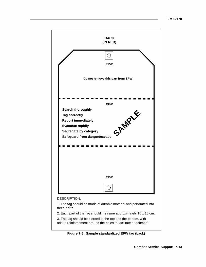
FM 5-170
Figure 7-5. Sample standardized EPW tag (back)
EPW
SAMPLE
Do not remove this part from EPW
EPW
Search thoroughly
Tag correctly
Report immediately
Evacuate rapidly
Segregate by category
Safeguard from danger/escape
EPW
DESCRIPTION:
1. The tag should be made of durable material and perforated into three parts.
2. Each part of the tag should measure approximately 10 x 15 cm.
3. The tag should be pierced at the top and the bottom, with added reinforcement around the holes to facilitate attachment.
BACK(IN RED)
Combat Service Support 7-13
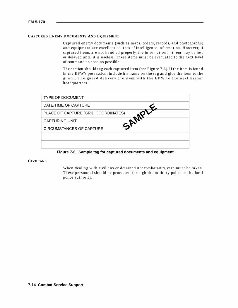
FM 5-170
CAPTURED ENEMY DOCUMENTS AND EQUIPMENT
Captured enemy documents (such as maps, orders, records, and photographs)and equipment are excellent sources of intelligence information. However, ifcaptured items are not handled properly, the information in them may be lostor delayed until it is useless. These items must be evacuated to the next levelof command as soon as possible.
The section should tag each captured item (see Figure 7-6). If the item is foundin the EPW's possession, include his name on the tag and give the item to theguard. The guard delivers the item with the EPW to the next higherheadquarters.
CIVILIANS
When dealing with civilians or detained noncombatants, care must be taken.These personnel should be processed through the military police or the localpolice authority.
TYPE OF DOCUMENT
DATE/TIME OF CAPTURE
PLACE OF CAPTURE (GRID COORDINATES)
CAPTURING UNIT
CIRCUMSTANCES OF CAPTURE
Figure 7-6. Sample tag for captured documents and equipment
SAMPLE
7-14 Combat Service Support
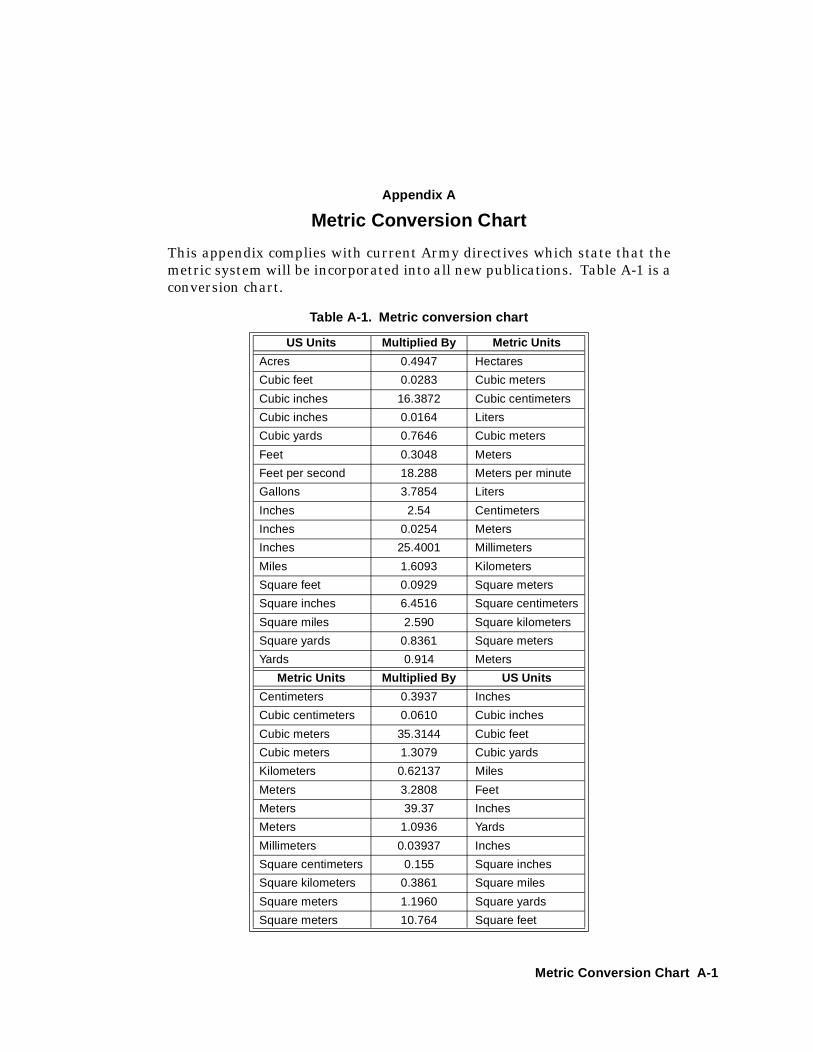
Appendix A
Metric Conversion Chart
This appendix complies with current Army directives which state that themetric system will be incorporated into all new publications. Table A-1 is aconversion chart.
Table A-1. Metric conversion chart
US Units Multiplied By Metric Units
Acres 0.4947 Hectares
Cubic feet 0.0283 Cubic meters
Cubic inches 16.3872 Cubic centimeters
Cubic inches 0.0164 Liters
Cubic yards 0.7646 Cubic meters
Feet 0.3048 Meters
Feet per second 18.288 Meters per minute
Gallons 3.7854 Liters
Inches 2.54 Centimeters
Inches 0.0254 Meters
Inches 25.4001 Millimeters
Miles 1.6093 Kilometers
Square feet 0.0929 Square meters
Square inches 6.4516 Square centimeters
Square miles 2.590 Square kilometers
Square yards 0.8361 Square meters
Yards 0.914 Meters
Metric Units Multiplied By US Units
Centimeters 0.3937 Inches
Cubic centimeters 0.0610 Cubic inches
Cubic meters 35.3144 Cubic feet
Cubic meters 1.3079 Cubic yards
Kilometers 0.62137 Miles
Meters 3.2808 Feet
Meters 39.37 Inches
Meters 1.0936 Yards
Millimeters 0.03937 Inches
Square centimeters 0.155 Square inches
Square kilometers 0.3861 Square miles
Square meters 1.1960 Square yards
Square meters 10.764 Square feet
Metric Conversion Chart A-1

FM 5-170
A-2 Metric Conversion Chart
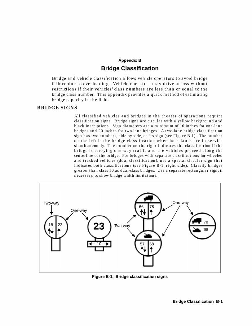
Appendix B
Bridge Classification
Bridge and vehicle classification allows vehicle operators to avoid bridgefailure due to overloading. Vehicle operators may drive across withoutrestrictions if their vehicles’ class numbers are less than or equal to thebridge class number. This appendix provides a quick method of estimatingbridge capacity in the field.
BRIDGE SIGNS
All classified vehicles and bridges in the theater of operations requireclassification signs. Bridge signs are circular with a yellow background andblack inscriptions. Sign diameters are a minimum of 16 inches for one-lanebridges and 20 inches for two-lane bridges. A two-lane bridge classificationsign has two numbers, side by side, on its sign (see Figure B-1). The numberon the left is the bridge classification when both lanes are in servicesimultaneously. The number on the right indicates the classification if thebridge is carrying one-way traffic and the vehicles proceed along thecenterline of the bridge. For bridges with separate classifications for wheeledand tracked vehicles (dual classification), use a special circular sign thatindicates both classifications (see Figure B-1, right side). Classify bridgesgreater than class 50 as dual-class bridges. Use a separate rectangular sign, ifnecessary, to show bridge width limitations.
Figure B-1. Bridge classification signs
10'
66 78One-way
23 Two-way
One-wayTwo-way
18 23
57 68
78
68
Bridge Classification B-1
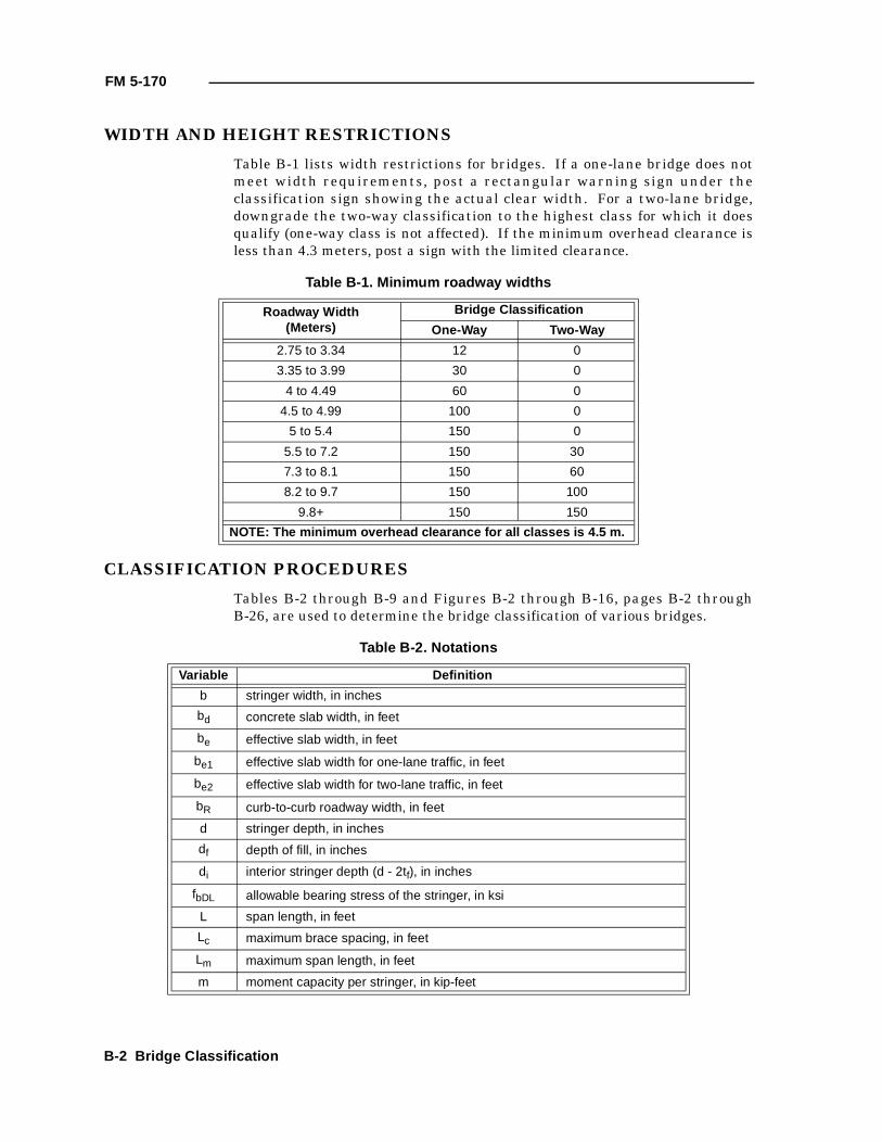
FM 5-170
WIDTH AND HEIGHT RESTRICTIONS
Table B-1 lists width restrictions for bridges. If a one-lane bridge does notmeet width requirements, post a rectangular warning sign under theclassification sign showing the actual clear width. For a two-lane bridge,downgrade the two-way classification to the highest class for which it doesqualify (one-way class is not affected). If the minimum overhead clearance isless than 4.3 meters, post a sign with the limited clearance.
CLASSIFICATION PROCEDURES
Tables B-2 through B-9 and Figures B-2 through B-16, pages B-2 throughB-26, are used to determine the bridge classification of various bridges.
Table B-1. Minimum roadway widths
Roadway Width(Meters)
Bridge Classification
One-Way Two-Way
2.75 to 3.34 12 0
3.35 to 3.99 30 0
4 to 4.49 60 0
4.5 to 4.99 100 0
5 to 5.4 150 0
5.5 to 7.2 150 30
7.3 to 8.1 150 60
8.2 to 9.7 150 100
9.8+ 150 150
NOTE: The minimum overhead clearance for all classes is 4.5 m.
Table B-2. Notations
Variable Definition
b stringer width, in inches
bd concrete slab width, in feet
be effective slab width, in feet
be1 effective slab width for one-lane traffic, in feet
be2 effective slab width for two-lane traffic, in feet
bR curb-to-curb roadway width, in feet
d stringer depth, in inches
df depth of fill, in inches
di interior stringer depth (d - 2tf), in inches
fbDL allowable bearing stress of the stringer, in ksi
L span length, in feet
Lc maximum brace spacing, in feet
Lm maximum span length, in feet
m moment capacity per stringer, in kip-feet
B-2 Bridge Classification

FM 5-170
mDL dead-load moment per stringer, in kip-feet
MDL dead-load moment for entire span, in kip-feet
mLL live-load moment per stringer, in kip-feet
MLL live-load moment per lane, in kip-feet
MLL1 live-load moment for one-lane traffic, in kip-feet
MLL2 live-load moment for two-lane traffic, in kip-feet
Nb number of braces
NL number of lanes
NS total number of stringers in the span
N1 effective number of stringers for one-lane traffic
N2 effective number of stringers for two-lane traffic
PLC provisional load class
R rise of arch, in feet
S section modulus, in cubic inches
Sb actual brace spacing, in feet
Sc section modulus of the composite section, in cubic inches
Ss center-to-center stringer spacing, in feet
tc crown thickness, in inches
td average deck thickness, in inches
teff effective deck thickness, in inches
tf flange thickness, in inches
tpl plate thickness, in inches
tw web thickness, in inches
tx thickness factor
T1 one-lane, tracked-vehicle classification
T2 two-lane, tracked-vehicle classification
v shear capacity per stringer, in kips
vDL dead-load shear per stringer, in kips
VDL estimated dead-load shear of span, in kips
vLL Iive-load shear per stringer, in kips
VLL live-load shear per lane, in kips
Ws stringer weight, in lbs/ft
W1 one-lane, wheeled-vehicle classification
W2 two-lane, wheeled-vehicle classification
Xpl plate thickness factor
%lam percent of lamination
Table B-2. Notations (continued)
Variable Definition
Bridge Classification B-3
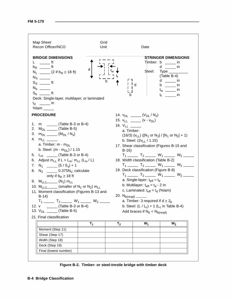
FM 5-170
Figure B-2. Timber- or steel-trestle bridge with timber deck
Map Sheet GridRecon Officer/NCO Unit Date
d twtf
d
b
BRIDGE DIMENSIONSL _____ ftbR _____ ftNL _____ (2 if bR > 18 ft)NS _____SS _____ ftNb _____Sb _____ ftDeck: Single-layer, multilayer, or laminatedtd _____ in%lam _____
STRINGER DIMENSIONSTimber: b _____ in
d _____ inSteel: Type _________
(Table B-4)d _____ inb _____ intw _____ intf _____ in
PROCEDURE
1. m _____ (Table B-3 or B-4)2. MDL _____ (Table B-5)3. mDL _____ (MDL / Ns)4. mLL _____
a. Timber: m - mDLb. Steel: (m - mDL) / 1.15
5. Lm _____ (Table B-3 or B-4)6. Adjust mLL if L > Lm: mLL (Lm / L)7. N1 _____ (5 / Ss) + 18. N2 _____ 0.375Ns; calculate
only if bR > 18 ft9. MLL1_____ (N1) mLL
10. MLL2_____ (smaller of N1 or N2) mLL11. Moment classification (Figures B-13 and
B-14)T1 _____ T2 _____ W1 _____ W2 _____
12. v _____ (Table B-3 or B-4)13. VDL _____ (Table B-5)
14. vDL _____ (VDL / Ns)15. vLL _____ (v - vDL)16. VLL _____
a. Timber:(16/3) (vLL) ([N1 or N2] / [N1 or N2] + 1)b. Steel: (2vLL / 1.15)
17. Shear classification (Figures B-15 andB-16)T1 _____ T2 _____ W1 _____ W2 _____
18. Width classification (Table B-2)T1 _____ T2 _____ W1 _____ W2 _____
19. Deck classification (Figure B-8)T1 _____ T2 _____ W1 _____ W2 _____a. Single-layer: teff = tdb. Multilayer: teff = td - 2 inc. Laminated: teff = td (%lam)
20. Nb(reqd) _____a. Timber: 3 required if d > 2bb. Steel: (L / Lc) + 1 (Lc in Table B-4)Add braces if Nb < Nb(reqd)
21. Final classification T1 T2 W1 W2
Moment (Step 11)
Shear (Step 17)
Width (Step 18)
Deck (Step 19)
Final (lowest number)
b
B-4 Bridge Classification
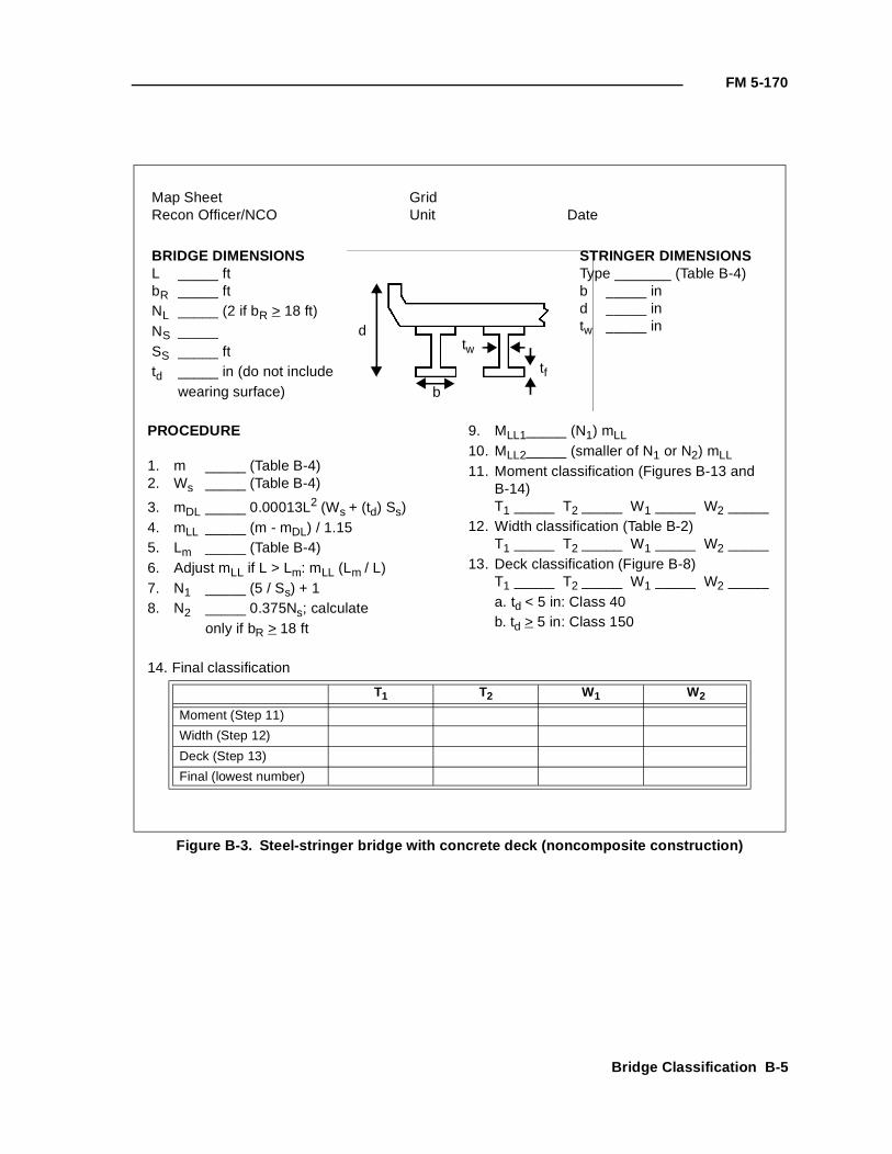
FM 5-170
Figure B-3. Steel-stringer bridge with concrete deck (noncomposite construction)
d
b
twtf
PROCEDURE
1. m _____ (Table B-4)2. Ws _____ (Table B-4)
3. mDL _____ 0.00013L2 (Ws + (td) Ss)4. mLL _____ (m - mDL) / 1.155. Lm _____ (Table B-4)6. Adjust mLL if L > Lm: mLL (Lm / L)7. N1 _____ (5 / Ss) + 18. N2 _____ 0.375Ns; calculate
only if bR > 18 ft
9. MLL1_____ (N1) mLL10. MLL2_____ (smaller of N1 or N2) mLL
11. Moment classification (Figures B-13 andB-14)T1 _____ T2 _____ W1 _____ W2 _____
12. Width classification (Table B-2)T1 _____ T2 _____ W1 _____ W2 _____
13. Deck classification (Figure B-8)T1 _____ T2 _____ W1 _____ W2 _____a. td < 5 in: Class 40b. td > 5 in: Class 150
Map Sheet GridRecon Officer/NCO Unit Date
BRIDGE DIMENSIONSL _____ ftbR _____ ftNL _____ (2 if bR > 18 ft)NS _____SS _____ fttd _____ in (do not include
wearing surface)
STRINGER DIMENSIONSType _______ (Table B-4)b _____ ind _____ intw _____ in
14. Final classification T1 T2 W1 W2
Moment (Step 11)
Width (Step 12)
Deck (Step 13)
Final (lowest number)
Bridge Classification B-5
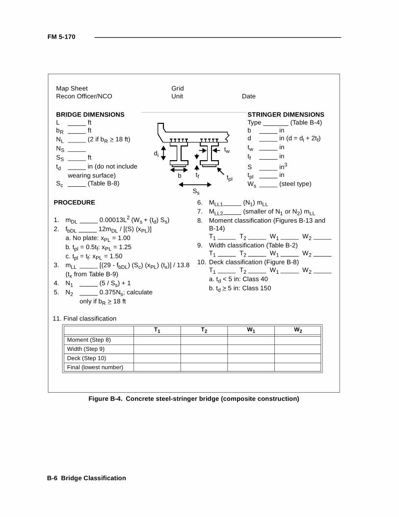
FM 5-170
Figure B-4. Concrete steel-stringer bridge (composite construction)
PROCEDURE
1. mDL _____ 0.00013L2 (Ws + (td) Ss)2. fbDL _____ 12mDL / [(S) (xPL)]
a. No plate: xPL = 1.00b. tpl = 0.5tf: xPL = 1.25c. tpl = tf: xPL = 1.50
3. mLL _____ [(29 - fbDL) (Sc) (xPL) (tx)] / 13.8(tx from Table B-9)
4. N1 _____ (5 / Ss) + 15. N2 _____ 0.375Ns; calculate
only if bR > 18 ft
6. MLL1_____ (N1) mLL7. MLL2_____ (smaller of N1 or N2) mLL8. Moment classification (Figures B-13 and
B-14)T1 _____ T2 _____ W1 _____ W2 _____
9. Width classification (Table B-2)T1 _____ T2 _____ W1 _____ W2 _____
10. Deck classification (Figure B-8)T1 _____ T2 _____ W1 _____ W2 _____a. td < 5 in: Class 40b. td > 5 in: Class 150
Map Sheet GridRecon Officer/NCO Unit Date
11. Final classification T1 T2 W1 W2
Moment (Step 8)
Width (Step 9)
Deck (Step 10)
Final (lowest number)
BRIDGE DIMENSIONSL _____ ftbR _____ ftNL _____ (2 if bR > 18 ft)NS _____SS _____ fttd _____ in (do not include
wearing surface)Sc _____ (Table B-8)
STRINGER DIMENSIONSType _______ (Table B-4)b _____ ind _____ in (d = di + 2tf)tw _____ intf _____ in
S _____ in3
tpl _____ inWs _____ (steel type)
di
b
tw
tf tpl
Ss
B-6 Bridge Classification
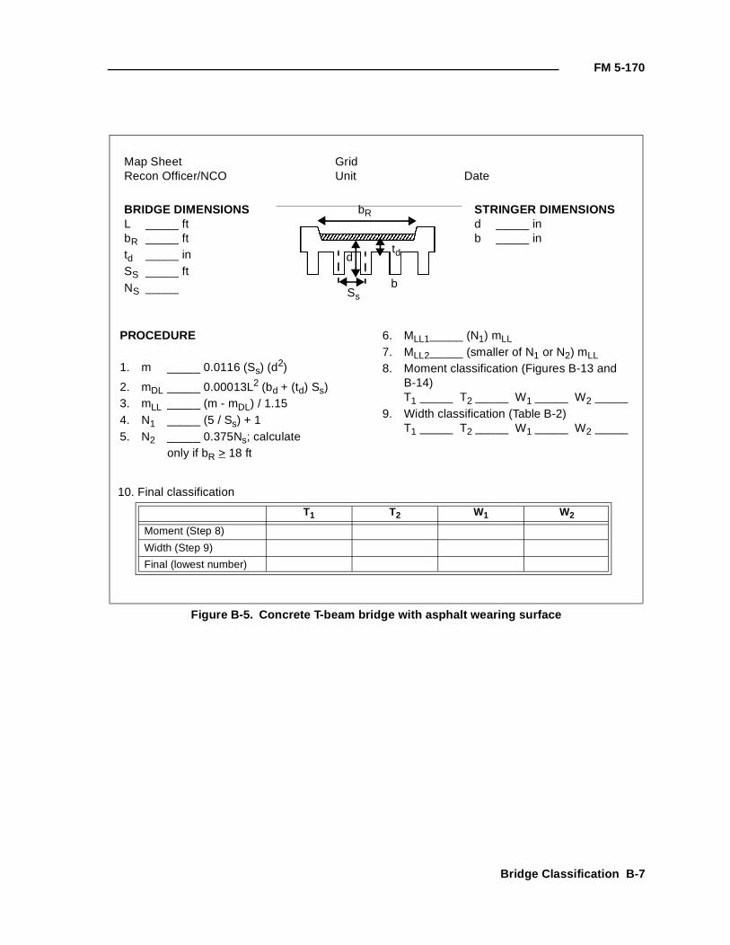
FM 5-170
Figure B-5. Concrete T-beam bridge with asphalt wearing surface
PROCEDURE
1. m _____ 0.0116 (Ss) (d2)
2. mDL _____ 0.00013L2 (bd + (td) Ss)3. mLL _____ (m - mDL) / 1.154. N1 _____ (5 / Ss) + 15. N2 _____ 0.375Ns; calculate
only if bR > 18 ft
6. MLL1_____ (N1) mLL
7. MLL2_____ (smaller of N1 or N2) mLL8. Moment classification (Figures B-13 and
B-14)T1 _____ T2 _____ W1 _____ W2 _____
9. Width classification (Table B-2)T1 _____ T2 _____ W1 _____ W2 _____
Map Sheet GridRecon Officer/NCO Unit Date
10. Final classification T1 T2 W1 W2
Moment (Step 8)
Width (Step 9)
Final (lowest number)
BRIDGE DIMENSIONSL _____ ftbR _____ fttd _____ inSS _____ ftNS _____
STRINGER DIMENSIONSd _____ inb _____ in
bR
d
Ss
td
b
Bridge Classification B-7
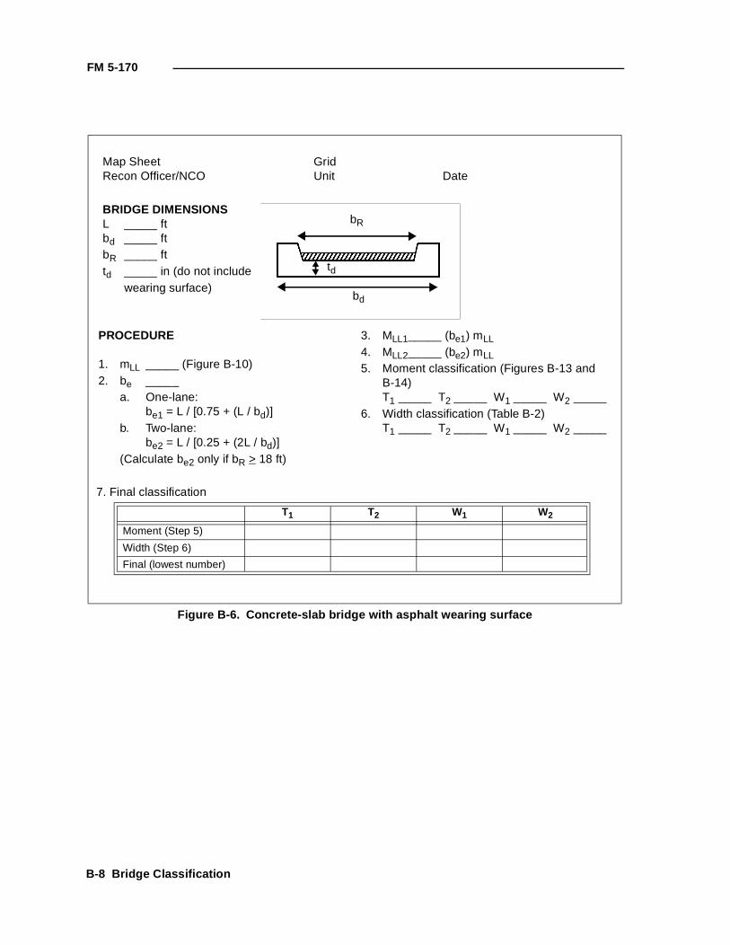
FM 5-170
Figure B-6. Concrete-slab bridge with asphalt wearing surface
PROCEDURE
1. mLL _____ (Figure B-10)2. be _____
a. One-lane:be1 = L / [0.75 + (L / bd)]
b. Two-lane:be2 = L / [0.25 + (2L / bd)]
(Calculate be2 only if bR > 18 ft)
3. MLL1_____ (be1) mLL
4. MLL2_____ (be2) mLL5. Moment classification (Figures B-13 and
B-14)T1 _____ T2 _____ W1 _____ W2 _____
6. Width classification (Table B-2)T1 _____ T2 _____ W1 _____ W2 _____
Map Sheet GridRecon Officer/NCO Unit Date
7. Final classification T1 T2 W1 W2
Moment (Step 5)
Width (Step 6)
Final (lowest number)
BRIDGE DIMENSIONSL _____ ftbd _____ ftbR _____ fttd _____ in (do not include
wearing surface)bd
bR
td
B-8 Bridge Classification
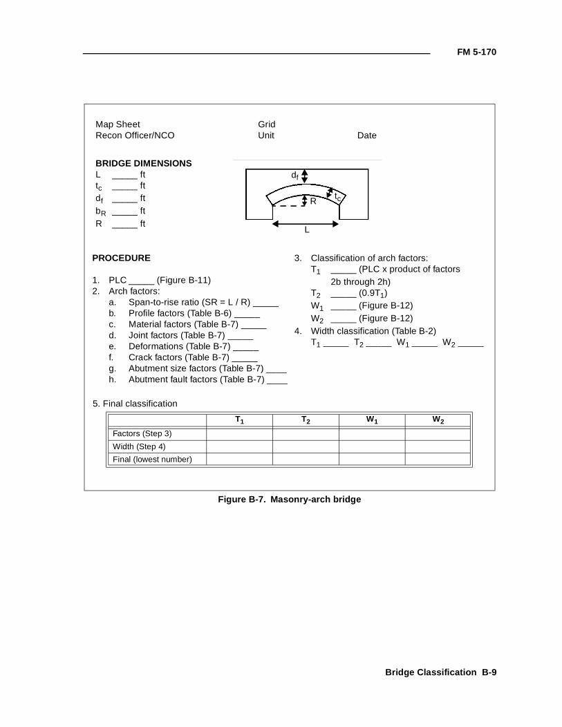
FM 5-170
Figure B-7. Masonry-arch bridge
PROCEDURE
1. PLC _____ (Figure B-11)2. Arch factors:
a. Span-to-rise ratio (SR = L / R) _____b. Profile factors (Table B-6) _____c. Material factors (Table B-7) _____d. Joint factors (Table B-7) _____e. Deformations (Table B-7) _____f. Crack factors (Table B-7) _____g. Abutment size factors (Table B-7) ____h. Abutment fault factors (Table B-7) ____
3. Classification of arch factors:T1 _____ (PLC x product of factors
2b through 2h)T2 _____ (0.9T1)W1 _____ (Figure B-12)W2 _____ (Figure B-12)
4. Width classification (Table B-2)T1 _____ T2 _____ W1 _____ W2 _____
Map Sheet GridRecon Officer/NCO Unit Date
5. Final classification T1 T2 W1 W2
Factors (Step 3)
Width (Step 4)
Final (lowest number)
BRIDGE DIMENSIONSL _____ fttc _____ ftdf _____ ftbR _____ ftR _____ ft
df
R
L
tc
Bridge Classification B-9
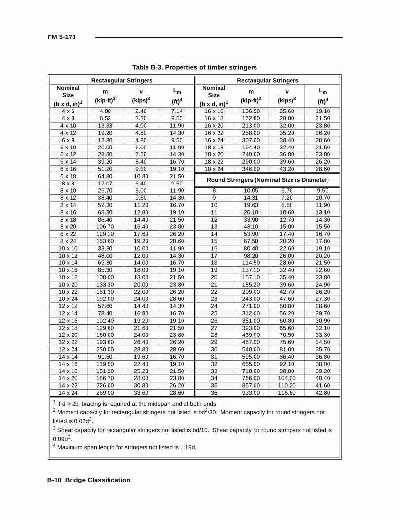
FM 5-170
Table B-3. Properties of timber stringers
Rectangular Stringers Rectangular StringersNominal
Size
(b x d, in) 1
m
(kip-ft) 2v
(kips) 3
Lm
(ft)4
NominalSize
(b x d, in) 1
m
(kip-ft) 2v
(kips) 3
Lm
(ft)4
4 x 6 4.80 2.40 7.14 16 x 16 136.50 25.60 19.104 x 8 8.53 3.20 9.50 16 x 18 172.80 28.80 21.504 x 10 13.33 4.00 11.90 16 x 20 213.00 32.00 23.804 x 12 19.20 4.80 14.30 16 x 22 258.00 35.20 26.206 x 8 12.80 4.80 9.50 16 x 24 307.00 38.40 28.606 x 10 20.00 6.00 11.90 18 x 18 194.40 32.40 21.506 x 12 28.80 7.20 14.30 18 x 20 240.00 36.00 23.806 x 14 39.20 8.40 16.70 18 x 22 290.00 39.60 26.206 x 16 51.20 9.60 19.10 18 x 24 346.00 43.20 28.606 x 18 64.80 10.80 21.50
Round Stringers (Nominal Size is Diameter)8 x 8 17.07 6.40 9.508 x 10 26.70 8.00 11.90 8 10.05 5.70 9.508 x 12 38.40 9.60 14.30 9 14.31 7.20 10.708 x 14 52.30 11.20 16.70 10 19.63 8.80 11.908 x 16 68.30 12.80 19.10 11 26.10 10.60 13.108 x 18 86.40 14.40 21.50 12 33.90 12.70 14.308 x 20 106.70 16.40 23.80 13 43.10 15.00 15.508 x 22 129.10 17.60 26.20 14 53.90 17.40 16.708 x 24 153.60 19.20 28.60 15 67.50 20.20 17.80
10 x 10 33.30 10.00 11.90 16 80.40 22.60 19.1010 x 12 48.00 12.00 14.30 17 98.20 26.00 20.2010 x 14 65.30 14.00 16.70 18 114.50 28.60 21.5010 x 16 85.30 16.00 19.10 19 137.10 32.40 22.6010 x 18 108.00 18.00 21.50 20 157.10 35.40 23.8010 x 20 133.30 20.00 23.80 21 185.20 39.60 24.9010 x 22 161.30 22.00 26.20 22 209.00 42.70 26.2010 x 24 192.00 24.00 28.60 23 243.00 47.60 27.3012 x 12 57.60 14.40 14.30 24 271.00 50.80 28.6012 x 14 78.40 16.80 16.70 25 312.00 56.20 29.7012 x 16 102.40 19.20 19.10 26 351.00 60.80 30.9012 x 18 129.60 21.60 21.50 27 393.00 65.60 32.1012 x 20 160.00 24.00 23.80 28 439.00 70.50 33.3012 x 22 193.60 26.40 26.20 29 487.00 75.60 34.5012 x 24 230.00 28.80 28.60 30 540.00 81.00 35.7014 x 14 91.50 19.60 16.70 31 595.00 86.40 36.8014 x 16 119.50 22.40 19.10 32 655.00 92.10 38.0014 x 18 151.20 25.20 21.50 33 718.00 98.00 39.2014 x 20 186.70 28.00 23.80 34 786.00 104.00 40.4014 x 22 226.00 30.80 26.20 35 857.00 110.20 41.6014 x 24 269.00 33.60 28.60 36 933.00 116.60 42.80
1 If d > 2b, bracing is required at the midspan and at both ends.2 Moment capacity for rectangular stringers not listed is bd2/30. Moment capacity for round stringers not
listed is 0.02d3.3 Shear capacity for rectangular stringers not listed is bd/10. Shear capacity for round stringers not listed is
0.09d2.4 Maximum span length for stringers not listed is 1.19d.
B-10 Bridge Classification

FM 5-170
Table B-4. Properties of steel stringers(Fy = 36 ksi, f b = 27 ksi, f v = 16.5 ksi)
Nominal Size
d(in)
b(in)
Tf(in)
tw(in)
m(kip-ft)
v(kips)
Lm(ft)
Lc(ft)
W39x211 39.250 11.750 1.438 0.75 1,770 450 100 12.4
W37x206 36.750 11.750 1.438 0.75 1,656 425 95 12.4
W36x300 36.750 16.625 1.688 0.94 2,486 520 94 17.6
W36x194 36.500 12.125 1.250 0.81 1,492 431 93 12.8
W36x182 36.375 12.125 1.187 0.75 1,397 406 93 12.8
W36x170 36.125 12.000 1.125 1.06 1,302 381 92 12.7
W36x160 36.000 12.000 1.000 1.06 1,217 365 92 12.7
W36x230 35.875 16.500 1.250 0.75 1,879 421 91 17.4
W36x150 35.875 12.000 0.937 0.62 1,131 350 91 12.7
W36x201 35.375 11.750 1.438 0.75 1,545 402 90 12.4
W33x196 33.375 11.750 1.438 0.75 1,433 377 85 12.4
W33x220 33.250 15.750 1.250 0.81 1,661 392 85 16.6
W33x141 33.250 11.500 0.937 0.62 1,005 313 85 12.1
W33x130 33.125 11.500 0.875 0.56 911 300 85 12.1
W33x200 33.000 15.575 1.125 0.56 1,506 362 84 16.6
W31x180 31.500 11.750 1.312 0.75 1,327 327 80 12.4
W30x124 30.125 10.500 0.937 0.68 797 273 77 11.1
W30x116 30.000 10.500 0.875 0.62 738 263 76 11.1
W30x108 29.875 10.500 0.750 0.56 672 255 76 11.1
W30x175 29.500 11.750 1.312 0.56 1,156 304 75 12.4
W27x171 27.500 11.750 1.312 0.68 1,059 282 70 12.4
W27x102 27.125 10.000 0.812 0.68 599 217 69 10.6
W27x94 26.875 10.000 0.750 0.50 546 205 68 10.6
W26X157 25.500 11.750 1.250 0.50 915 237 65 12.4
W24x94 24.250 9.000 0.875 0.62 497 191 62 9.5
W24x84 24.125 9.000 0.750 0.50 442 174 61 9.5
W24x100 24.000 12.000 0.750 0.50 560 173 61 12.7
S24x120 24.000 8.000 1.125 0.50 564 286 61 8.4
S24x106 24.000 7.875 1.125 1.18 527 224 61 8.3
S24x80 24.000 7.000 0.875 0.62 391 183 61 7.4
W24x76 23.875 9.000 0.687 0.50 394 163 61 9.5
W24x153 23.625 11.750 0.250 0.43 828 217 60 12.4
S24x134 23.625 8.500 1.250 0.62 634 283 60 9.0
S22x75 22.000 7.000 0.812 0.81 308 168 56 7.4
W21x139 21.625 11.750 1.187 0.50 699 198 55 12.4
S21x112 21.625 7.875 1.187 0.62 495 238 55 8.3
W21x73 21.250 8.250 0.750 0.75 338 148 54 8.7
W21x68 21.125 8.250 0.687 0.50 315 140 54 8.7
W21x62 21.000 8.250 0.625 0.43 284 130 53 8.7
Bridge Classification B-11
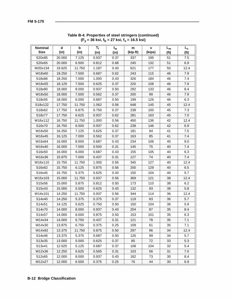
FM 5-170
S20x85 20.000 7.125 0.937 0.37 337 195 51 7.5
S20x65 20.000 6.500 0.812 0.68 245 132 51 6.9
W20x134 19.625 11.750 1.187 0.43 621 177 50 12.4
W18x60 18.250 7.500 0.687 0.62 243 115 46 7.9
S18x86 18.250 7.000 1.000 0.43 326 184 46 7.4
W18x55 18.125 7.500 0.625 0.37 220 108 46 7.9
S18x80 18.000 8.000 0.937 0.50 292 133 46 8.4
W18x50 18.000 7.500 0.562 0.37 200 99 46 7.9
S18x55 18.000 6.000 0.687 0.50 199 126 46 6.3
S18x122 17.750 11.750 1.062 0.56 648 145 45 12.4
S18x62 17.750 6.875 0.750 0.37 238 100 45 7.3
S18x77 17.750 6.625 0.937 0.62 281 163 45 7.0
W16x112 16.750 11.750 1.000 0.56 450 136 42 12.4
S16x70 16.750 6.500 0.937 0.62 238 146 42 6.9
W16x50 16.250 7.125 0.625 0.37 181 94 41 7.5
W16x45 16.125 7.000 0.562 0.37 163 85 41 7.4
W16x64 16.000 8.500 0.687 0.43 234 106 40 9.0
W16x40 16.000 7.000 0.500 0.31 145 75 40 7.4
S16x50 16.000 6.000 0.687 0.43 155 105 40 6.3
W16x36 15.875 7.000 0.437 0.31 127 74 40 7.4
W16x110 15.750 11.750 1.000 0.56 345 127 40 12.4
S16x62 15.750 6.125 0.875 0.56 200 129 40 6.5
S16x45 15.750 5.375 0.625 0.43 150 104 40 5.7
W15x103 15.000 11.750 0.937 0.56 369 121 38 12.4
S15x56 15.000 5.875 0.812 0.50 173 110 38 6.2
S15x43 15.000 5.500 0.625 0.43 132 93 38 5.8
W14x101 14.250 11.750 0.937 0.56 344 114 36 12.4
S14x40 14.250 5.375 0.375 0.37 119 83 36 5.7
S14x51 14.125 5.625 0.750 0.50 150 104 36 5.9
S14x70 14.000 8.000 0.937 0.43 204 87 35 8.4
S14x57 14.000 6.000 0.875 0.50 153 101 35 6.3
W14x34 14.000 6.750 0.437 0.31 121 78 35 7.1
W14x30 13.875 6.750 0.375 0.25 109 61 35 7.1
W14x92 13.375 11.750 0.875 0.50 297 96 34 12.4
S14x46 13.375 5.375 0.687 0.50 126 99 34 5.7
S13x35 13.000 5.000 0.625 0.37 85 72 33 5.3
S13x41 12.625 5.125 0.687 0.37 108 104 32 5.4
W12x36 12.250 6.625 0.565 0.31 103 56 31 7.0
S12x65 12.000 8.000 0.937 0.43 182 73 30 8.4
W12x27 12.000 6.500 0.375 0.25 76 44 30 6.9
Table B-4. Properties of steel stringers (continued)(Fy = 36 ksi, f b = 27 ksi, f v = 16.5 ksi)
Nominal Size
d(in)
b(in)
Tf(in)
tw(in)
m(kip-ft)
v(kips)
Lm(ft)
Lc(ft)
B-12 Bridge Classification
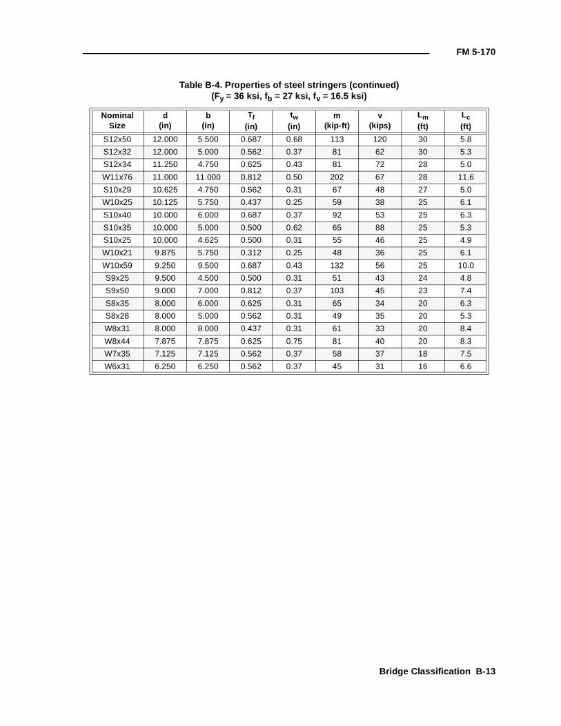
FM 5-170
S12x50 12.000 5.500 0.687 0.68 113 120 30 5.8
S12x32 12.000 5.000 0.562 0.37 81 62 30 5.3
S12x34 11.250 4.750 0.625 0.43 81 72 28 5.0
W11x76 11.000 11.000 0.812 0.50 202 67 28 11.6
S10x29 10.625 4.750 0.562 0.31 67 48 27 5.0
W10x25 10.125 5.750 0.437 0.25 59 38 25 6.1
S10x40 10.000 6.000 0.687 0.37 92 53 25 6.3
S10x35 10.000 5.000 0.500 0.62 65 88 25 5.3
S10x25 10.000 4.625 0.500 0.31 55 46 25 4.9
W10x21 9.875 5.750 0.312 0.25 48 36 25 6.1
W10x59 9.250 9.500 0.687 0.43 132 56 25 10.0
S9x25 9.500 4.500 0.500 0.31 51 43 24 4.8
S9x50 9.000 7.000 0.812 0.37 103 45 23 7.4
S8x35 8.000 6.000 0.625 0.31 65 34 20 6.3
S8x28 8.000 5.000 0.562 0.31 49 35 20 5.3
W8x31 8.000 8.000 0.437 0.31 61 33 20 8.4
W8x44 7.875 7.875 0.625 0.75 81 40 20 8.3
W7x35 7.125 7.125 0.562 0.37 58 37 18 7.5
W6x31 6.250 6.250 0.562 0.37 45 31 16 6.6
Table B-4. Properties of steel stringers (continued)(Fy = 36 ksi, f b = 27 ksi, f v = 16.5 ksi)
Nominal Size
d(in)
b(in)
Tf(in)
tw(in)
m(kip-ft)
v(kips)
Lm(ft)
Lc(ft)
Bridge Classification B-13
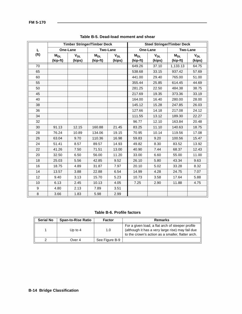
FM 5-170
Table B-5. Dead-load moment and shear
L(ft)
Timber Stringer/Timber Deck Steel Stringer/Timber Deck
One-Lane Two-Lane One-Lane Two-Lane
MDL(kip-ft)
VDL(kips)
MDL(kip-ft)
VDL(kips)
MDL(kip-ft)
VDL(kips)
MDL(kip-ft)
VDL(kips)
70 649.26 37.10 1,133.13 64.75
65 538.68 33.15 937.42 57.69
60 441.00 29.40 765.00 51.00
55 355.44 25.85 614.45 44.69
50 281.25 22.50 484.38 38.75
45 217.69 19.35 373.36 33.19
40 164.00 16.40 280.00 28.00
38 145.12 15.28 247.85 26.03
36 127.66 14.18 217.08 24.12
34 111.55 13.12 189.30 22.27
32 96.77 12.10 163.84 20.48
30 91.13 12.15 160.88 21.45 83.25 11.10 140.63 18.75
28 76.24 10.89 134.06 19.15 70.95 10.14 119.56 17.08
26 63.04 9.70 110.36 16.98 59.83 9.20 100.56 15.47
24 51.41 8.57 89.57 14.93 49.82 8.30 83.52 13.92
22 41.26 7.50 71.51 13.00 40.90 7.44 68.37 12.43
20 32.50 6.50 56.00 11.20 33.00 6.60 55.00 11.00
18 25.03 5.56 42.85 9.52 26.10 5.80 43.34 9.63
16 18.75 4.89 31.87 7.97 20.10 5.02 33.28 8.32
14 13.57 3.88 22.88 6.54 14.99 4.28 24.75 7.07
12 9.40 3.13 15.70 5.23 10.73 3.58 17.64 5.88
10 6.13 2.45 10.13 4.05 7.25 2.90 11.88 4.75
9 4.80 2.13 7.89 3.51
8 3.66 1.83 5.98 2.99
Table B-6. Profile factors
Serial No Span-to-Rise Ratio Factor Remarks
1 Up to 4 1.0For a given load, a flat arch of steeper profile (although it has a very large rise) may fail due to the crown’s action as a smaller, flatter arch.
2 Over 4 See Figure B-9
B-14 Bridge Classification
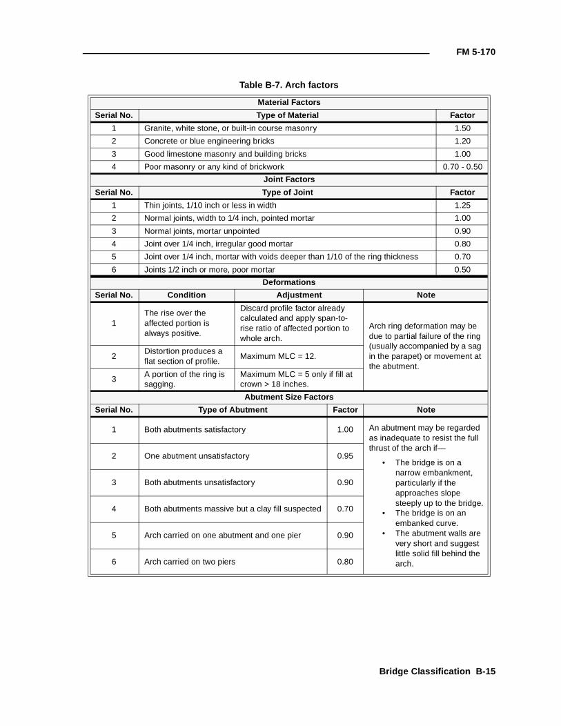
FM 5-170
Table B-7. Arch factors
Material Factors
Serial No. Type of Material Factor
1 Granite, white stone, or built-in course masonry 1.50
2 Concrete or blue engineering bricks 1.20
3 Good limestone masonry and building bricks 1.00
4 Poor masonry or any kind of brickwork 0.70 - 0.50
Joint Factors
Serial No. Type of Joint Factor
1 Thin joints, 1/10 inch or less in width 1.25
2 Normal joints, width to 1/4 inch, pointed mortar 1.00
3 Normal joints, mortar unpointed 0.90
4 Joint over 1/4 inch, irregular good mortar 0.80
5 Joint over 1/4 inch, mortar with voids deeper than 1/10 of the ring thickness 0.70
6 Joints 1/2 inch or more, poor mortar 0.50
Deformations
Serial No. Condition Adjustment Note
1The rise over the affected portion is always positive.
Discard profile factor already calculated and apply span-to-rise ratio of affected portion to whole arch.
Arch ring deformation may be due to partial failure of the ring (usually accompanied by a sag in the parapet) or movement at the abutment.
2Distortion produces a flat section of profile.
Maximum MLC = 12.
3A portion of the ring is sagging.
Maximum MLC = 5 only if fill at crown > 18 inches.
Abutment Size Factors
Serial No. Type of Abutment Factor Note
1 Both abutments satisfactory 1.00 An abutment may be regarded as inadequate to resist the full thrust of the arch if—
• The bridge is on a narrow embankment, particularly if the approaches slope steeply up to the bridge.
• The bridge is on an embanked curve.
• The abutment walls are very short and suggest little solid fill behind the arch.
2 One abutment unsatisfactory 0.95
3 Both abutments unsatisfactory 0.90
4 Both abutments massive but a clay fill suspected 0.70
5 Arch carried on one abutment and one pier 0.90
6 Arch carried on two piers 0.80
Bridge Classification B-15
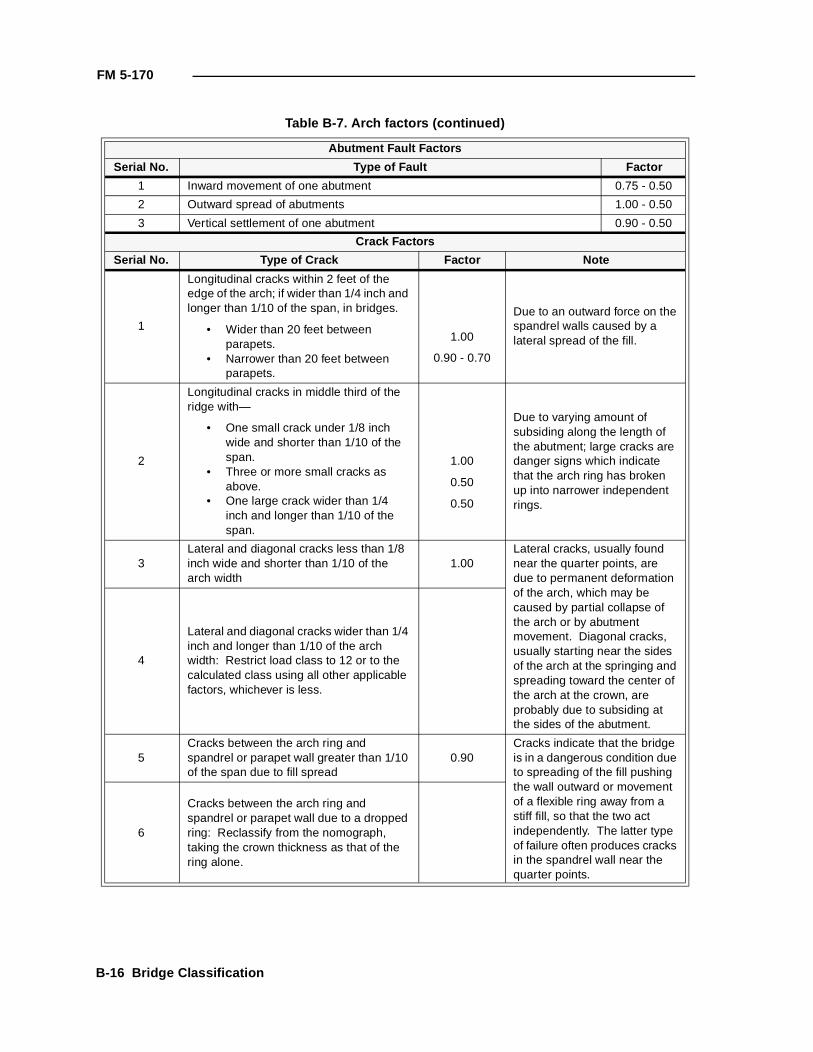
FM 5-170
Table B-7. Arch factors (continued)
Abutment Fault Factors
Serial No. Type of Fault Factor
1 Inward movement of one abutment 0.75 - 0.50
2 Outward spread of abutments 1.00 - 0.50
3 Vertical settlement of one abutment 0.90 - 0.50
Crack Factors
Serial No. Type of Crack Factor Note
1
Longitudinal cracks within 2 feet of the edge of the arch; if wider than 1/4 inch and longer than 1/10 of the span, in bridges.
• Wider than 20 feet between parapets.
• Narrower than 20 feet between parapets.
1.00
0.90 - 0.70
Due to an outward force on the spandrel walls caused by a lateral spread of the fill.
2
Longitudinal cracks in middle third of the ridge with—
• One small crack under 1/8 inch wide and shorter than 1/10 of the span.
• Three or more small cracks as above.
• One large crack wider than 1/4 inch and longer than 1/10 of the span.
1.00
0.50
0.50
Due to varying amount of subsiding along the length of the abutment; large cracks are danger signs which indicate that the arch ring has broken up into narrower independent rings.
3Lateral and diagonal cracks less than 1/8 inch wide and shorter than 1/10 of the arch width
1.00Lateral cracks, usually found near the quarter points, are due to permanent deformation of the arch, which may be caused by partial collapse of the arch or by abutment movement. Diagonal cracks, usually starting near the sides of the arch at the springing and spreading toward the center of the arch at the crown, are probably due to subsiding at the sides of the abutment.
4
Lateral and diagonal cracks wider than 1/4 inch and longer than 1/10 of the arch width: Restrict load class to 12 or to the calculated class using all other applicable factors, whichever is less.
5Cracks between the arch ring and spandrel or parapet wall greater than 1/10 of the span due to fill spread
0.90Cracks indicate that the bridge is in a dangerous condition due to spreading of the fill pushing the wall outward or movement of a flexible ring away from a stiff fill, so that the two act independently. The latter type of failure often produces cracks in the spandrel wall near the quarter points.
6
Cracks between the arch ring and spandrel or parapet wall due to a dropped ring: Reclassify from the nomograph, taking the crown thickness as that of the ring alone.
B-16 Bridge Classification
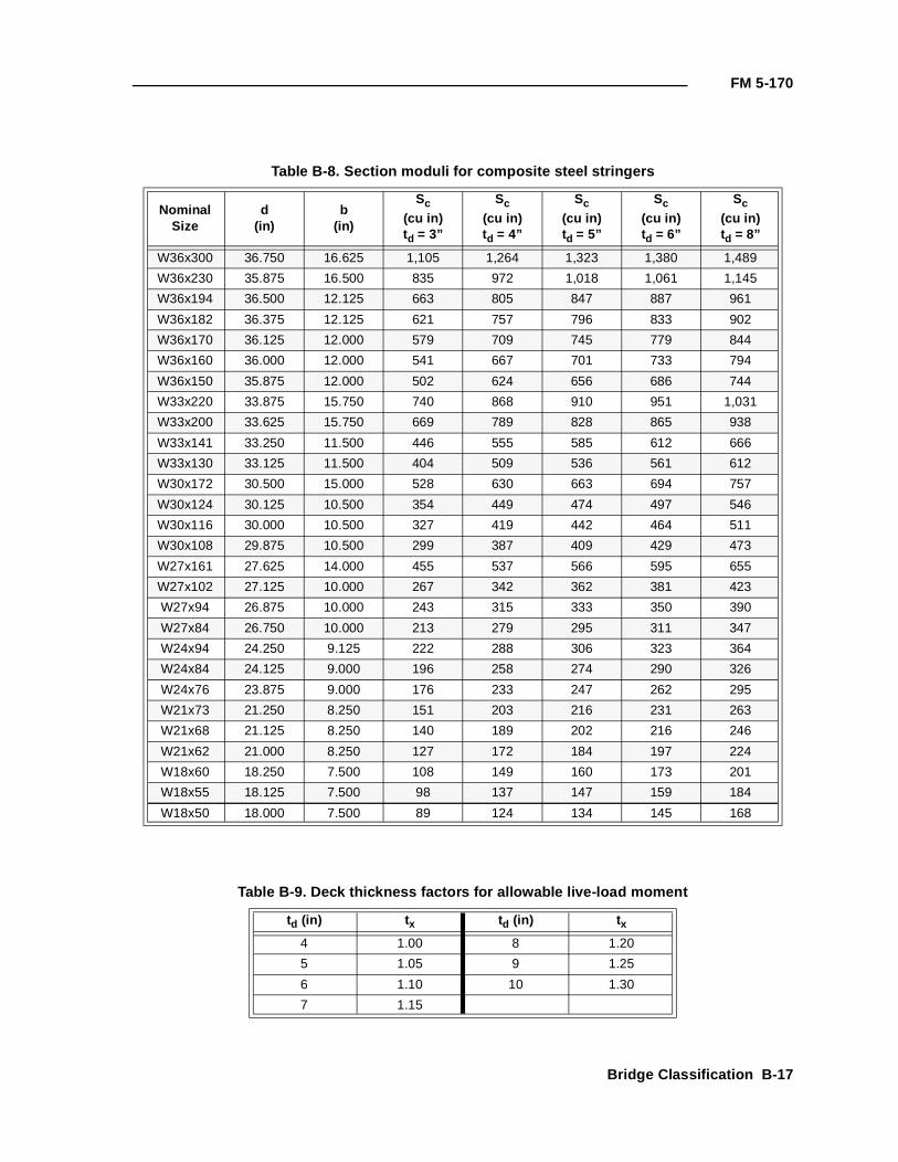
FM 5-170
Table B-8. Section moduli for composite steel stringers
Nominal Size
d(in)
b(in)
Sc
(cu in)td = 3”
Sc
(cu in)td = 4”
Sc
(cu in)td = 5”
Sc
(cu in)td = 6”
Sc
(cu in)td = 8”
W36x300 36.750 16.625 1,105 1,264 1,323 1,380 1,489
W36x230 35.875 16.500 835 972 1,018 1,061 1,145
W36x194 36.500 12.125 663 805 847 887 961
W36x182 36.375 12.125 621 757 796 833 902
W36x170 36.125 12.000 579 709 745 779 844
W36x160 36.000 12.000 541 667 701 733 794
W36x150 35.875 12.000 502 624 656 686 744
W33x220 33.875 15.750 740 868 910 951 1,031
W33x200 33.625 15.750 669 789 828 865 938
W33x141 33.250 11.500 446 555 585 612 666
W33x130 33.125 11.500 404 509 536 561 612
W30x172 30.500 15.000 528 630 663 694 757
W30x124 30.125 10.500 354 449 474 497 546
W30x116 30.000 10.500 327 419 442 464 511
W30x108 29.875 10.500 299 387 409 429 473
W27x161 27.625 14.000 455 537 566 595 655
W27x102 27.125 10.000 267 342 362 381 423
W27x94 26.875 10.000 243 315 333 350 390
W27x84 26.750 10.000 213 279 295 311 347
W24x94 24.250 9.125 222 288 306 323 364
W24x84 24.125 9.000 196 258 274 290 326
W24x76 23.875 9.000 176 233 247 262 295
W21x73 21.250 8.250 151 203 216 231 263
W21x68 21.125 8.250 140 189 202 216 246
W21x62 21.000 8.250 127 172 184 197 224
W18x60 18.250 7.500 108 149 160 173 201
W18x55 18.125 7.500 98 137 147 159 184
W18x50 18.000 7.500 89 124 134 145 168
Table B-9. Deck thickness factors for allowable live-load moment
td (in) t x td (in) t x
4 1.00 8 1.20
5 1.05 9 1.25
6 1.10 10 1.30
7 1.15
Bridge Classification B-17
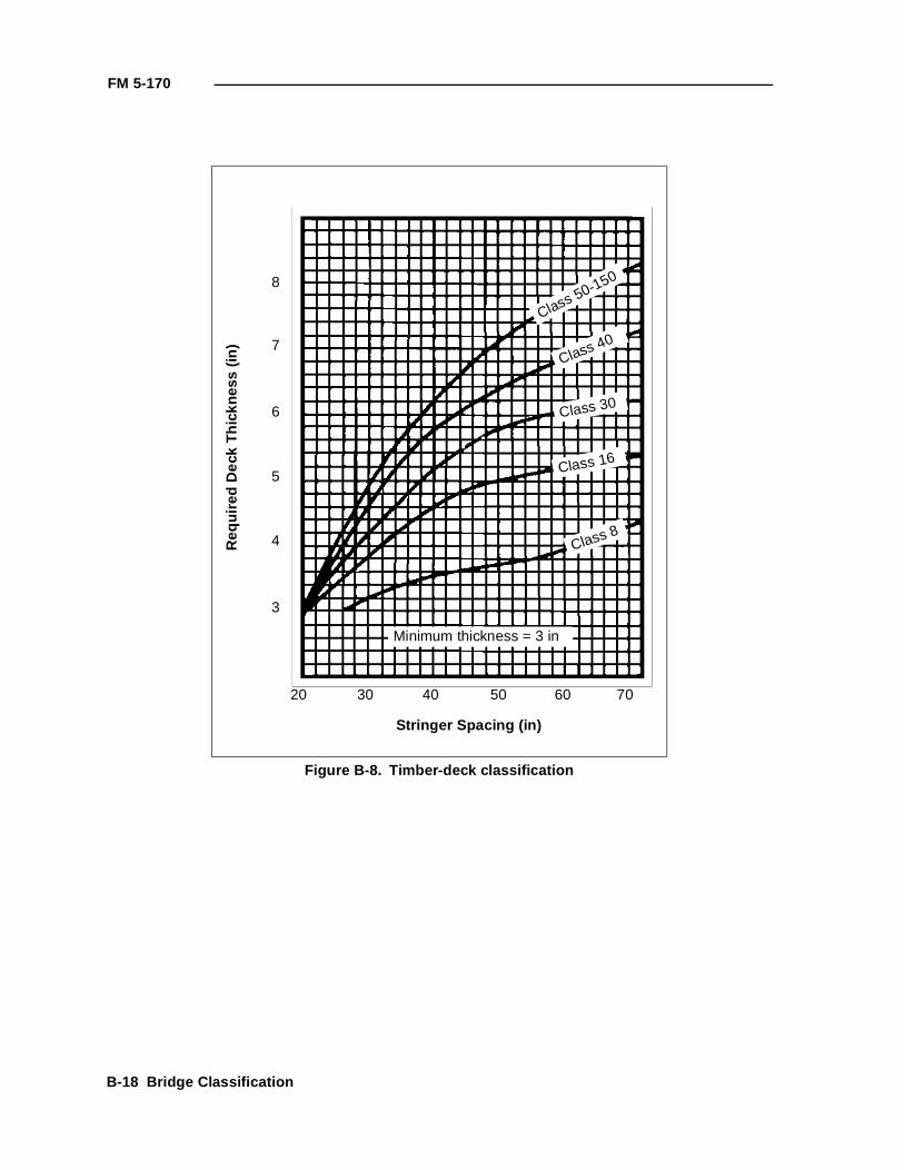
FM 5-170
Figure B-8. Timber-deck classification
3
4
5
6
7
8
20 30 40 50 60 70
Class 50-150
Class 40
Class 30
Class 16
Class 8
Minimum thickness = 3 in
Req
uire
d D
eck
Thi
ckne
ss (
in)
Stringer Spacing (in)
B-18 Bridge Classification
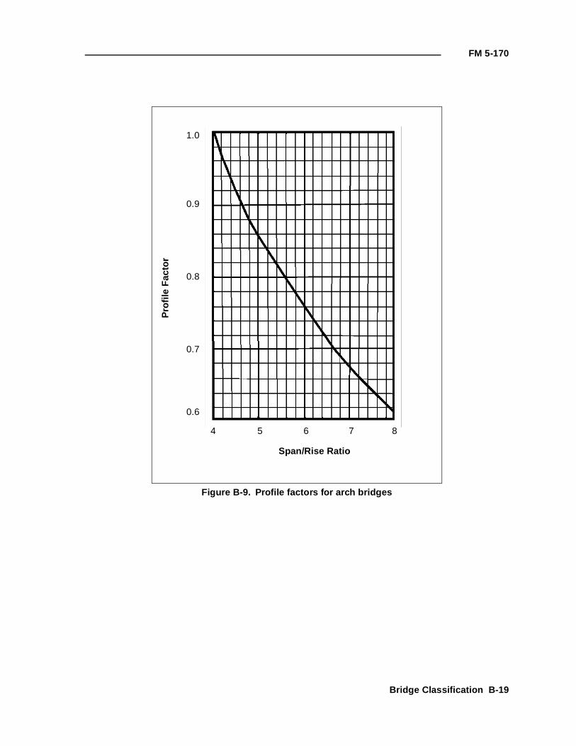
FM 5-170
Figure B-9. Profile factors for arch bridges
0.6
0.7
0.8
0.9
1.0
4 5 6 7 8
Pro
file
Fac
tor
Span/Rise Ratio
Bridge Classification B-19
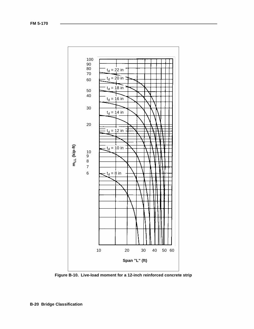
FM 5-170
Figure B-10. Live-load moment for a 12-inch reinforced concrete strip
10 20 30 40 50 60
6
78910
20
30
4050
60
708090100
Span "L" (ft)
mLL
(ki
p-ft)
td = 22 in
td = 20 in
td = 18 in
td = 16 in
td = 14 in
td = 12 in
td = 10 in
td = 8 in
B-20 Bridge Classification
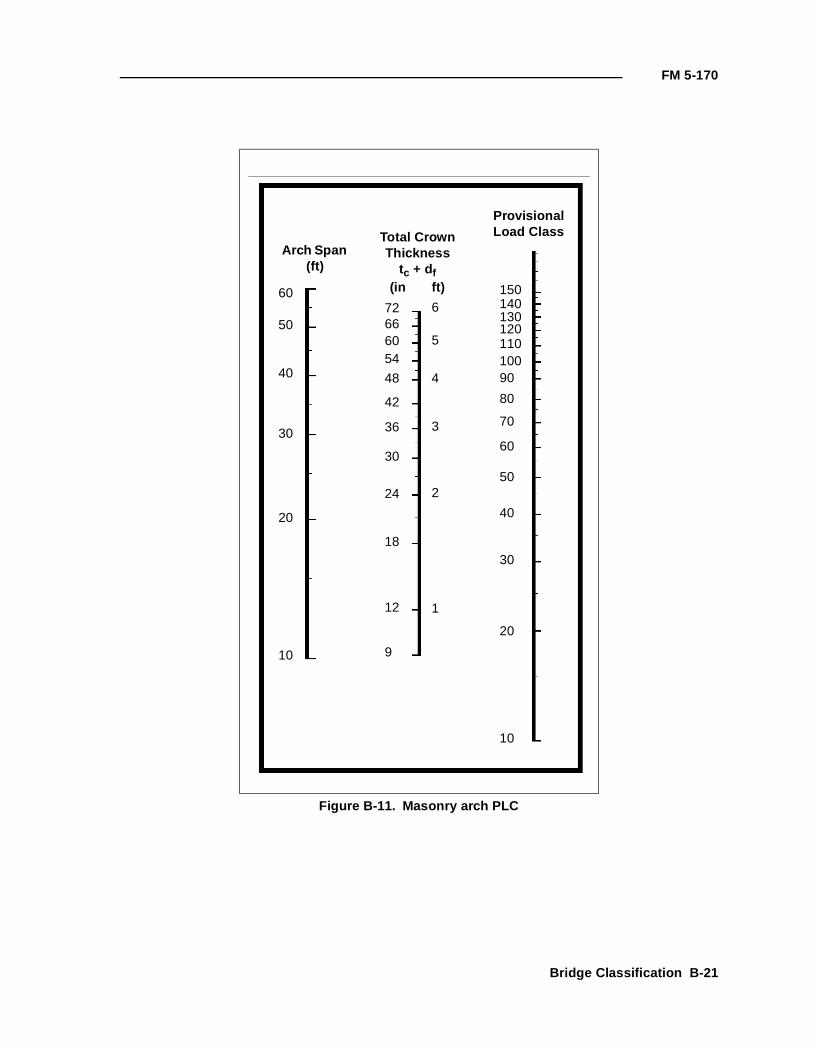
FM 5-170
Figure B-11. Masonry arch PLC
Arch Span (ft)
Total CrownThickness
tc + df(in ft)
ProvisionalLoad Class
60
50
40
30
20
10
72666054
48
42
36
30
24
18
12
9
6
5
4
3
2
1
15014013012011010090
80
70
60
50
40
30
20
10
Bridge Classification B-21
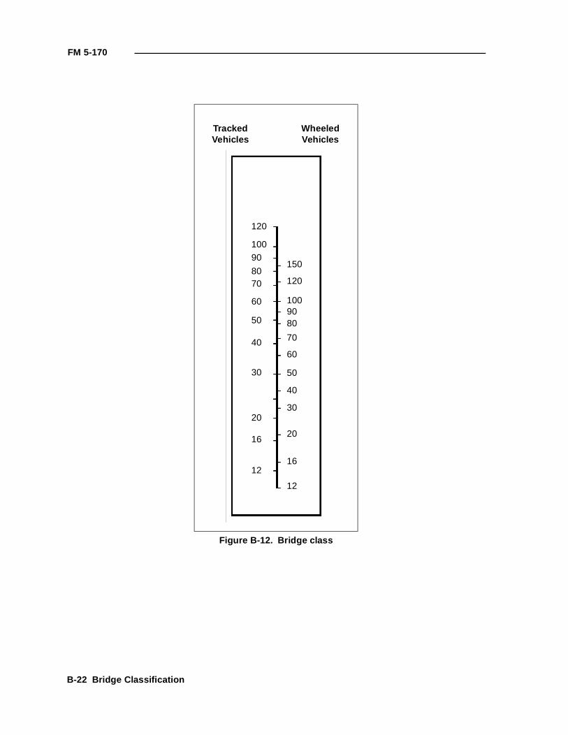
FM 5-170
Figure B-12. Bridge class
TrackedVehicles
WheeledVehicles
120
10090
8070
60
50
40
30
20
16
12
150
120
1009080
70
60
50
40
30
20
16
12
B-22 Bridge Classification
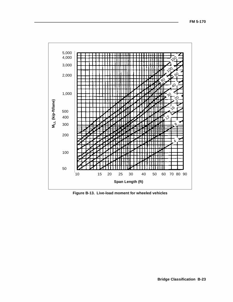
FM 5-170
Figure B-13. Live-load moment for wheeled vehicles
5,0004,000
3,000
2,000
1,000
500
400
300
200
100
50
10 15 20 25 30 40 50 60 70 80 90
150
Span Length (ft)
MLL
(ki
p-ft/
lane
)
100
8060
40
3020
16
8
4
12
Bridge Classification B-23
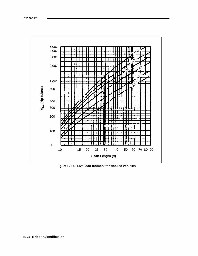
FM 5-170
Figure B-14. Live-load moment for tracked vehicles
5,0004,000
3,000
2,000
1,000
500
400
300
200
100
50
10 15 20 25 30 40 50 60 70 80 90
150
Span Length (ft)
MLL
(ki
p-ft/
lane
)
100
80 60
40
30
B-24 Bridge Classification
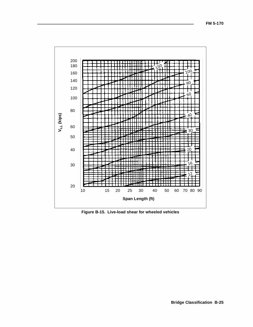
FM 5-170
Figure B-15. Live-load shear for wheeled vehicles
200180
140
120
100
80
60
50
40
30
2010 15 20 25 30 40 50 60 70 80 90
150
Span Length (ft)
VLL
(ki
ps)
100
80
60
40
30
160
20
16
12
Bridge Classification B-25
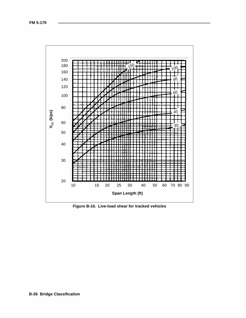
FM 5-170
Figure B-16. Live-load shear for tracked vehicles
200180
140
120
100
80
60
50
40
30
2010 15 20 25 30 40 50 60 70 80 90
150
Span Length (ft)
VLL
(ki
ps)
100
80
60
40
30
160
B-26 Bridge Classification
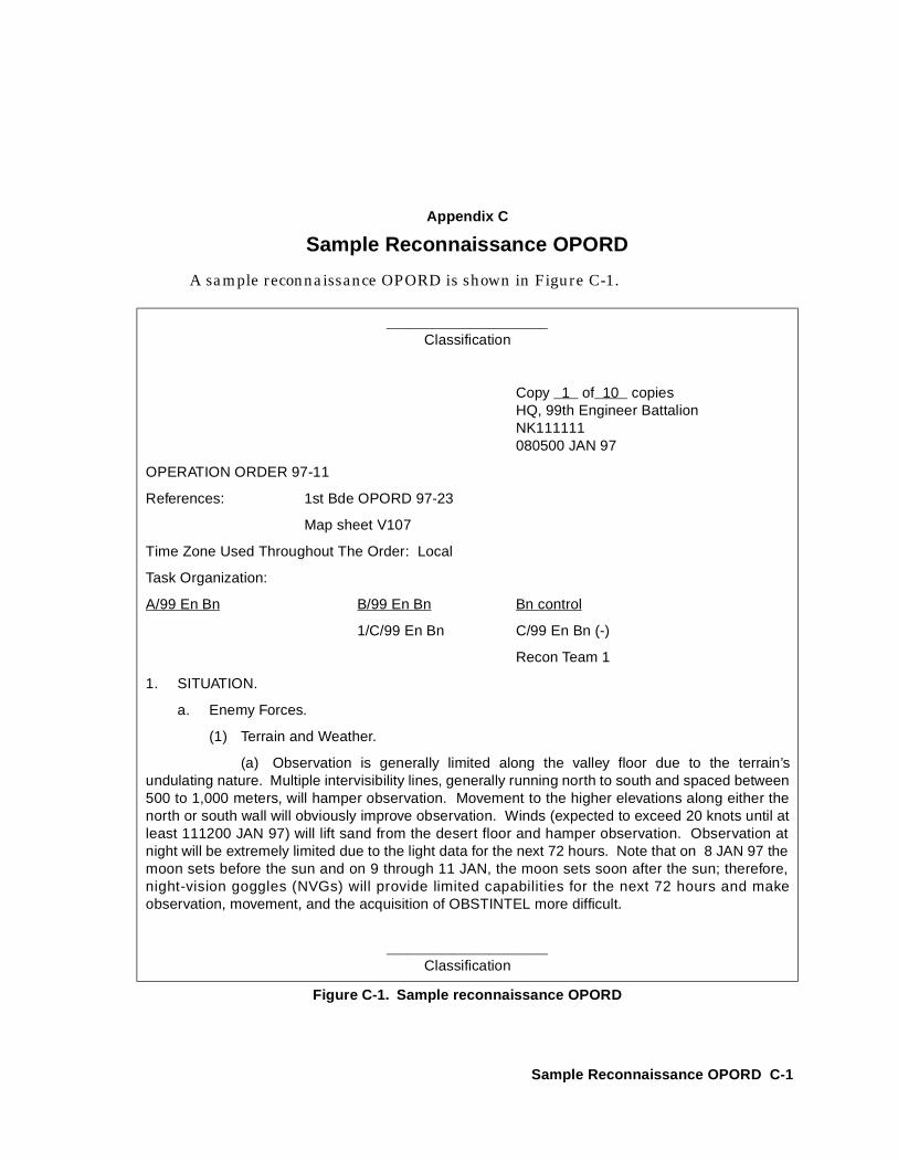
Appendix C
Sample Reconnaissance OPORD
A sample reconnaissance OPORD is shown in Figure C-1.
______________________Classification
Copy 1 of 10 copiesHQ, 99th Engineer BattalionNK111111080500 JAN 97
OPERATION ORDER 97-11
References: 1st Bde OPORD 97-23
Map sheet V107
Time Zone Used Throughout The Order: Local
Task Organization:
A/99 En Bn B/99 En Bn Bn control
1/C/99 En Bn C/99 En Bn (-)
Recon Team 1
1. SITUATION.
a. Enemy Forces.
(1) Terrain and Weather.
(a) Observation is generally limited along the valley floor due to the terrain’sundulating nature. Multiple intervisibility lines, generally running north to south and spaced between500 to 1,000 meters, will hamper observation. Movement to the higher elevations along either thenorth or south wall will obviously improve observation. Winds (expected to exceed 20 knots until atleast 111200 JAN 97) will lift sand from the desert floor and hamper observation. Observation atnight will be extremely limited due to the light data for the next 72 hours. Note that on 8 JAN 97 themoon sets before the sun and on 9 through 11 JAN, the moon sets soon after the sun; therefore,night-vision goggles (NVGs) will provide limited capabilities for the next 72 hours and makeobservation, movement, and the acquisition of OBSTINTEL more difficult.
______________________Classification
Figure C-1. Sample reconnaissance OPORD
Sample Reconnaissance OPORD C-1
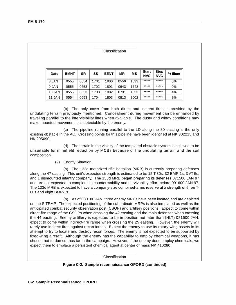
FM 5-170
______________________Classification
(b) The only cover from both direct and indirect fires is provided by theundulating terrain previously mentioned. Concealment during movement can be enhanced bytraveling parallel to the intervisibility lines when available. The dusty and windy conditions maymake mounted movement less detectable by the enemy.
(c) The pipeline running parallel to the LD along the 30 easting is the onlyexisting obstacle in the AO. Crossing points for this pipeline have been identified at NK 302215 andNK 295090.
(d) The terrain in the vicinity of the templated obstacle system is believed to beunsuitable for minefield reduction by MCBs because of the undulating terrain and the soilcomposition.
(2) Enemy Situation.
(a) The 133d motorized rifle battalion (MRB) is currently preparing defensesalong the 47 easting. This unit’s expected strength is estimated to be 12 T-80s, 32 BMP-1s, 3 AT-5s,and 1 dismounted infantry company. The 133d MRB began preparing its defenses 071500 JAN 97and are not expected to complete its countermobility and survivability effort before 091600 JAN 97.The 133d MRB is expected to have a company-size combined-arms reserve at a strength of three T-80s and eight BMP-1s.
(b) As of 080100 JAN, three enemy MRCs have been located and are depictedon the SITEMP. The expected positioning of the subordinate MRPs is also templated as well as theanticipated combat security observation post (CSOP) and artillery positions. Expect to come withindirect-fire range of the CSOPs when crossing the 42 easting and the main defenses when crossingthe 44 easting. Enemy artillery is expected to be in position not later than (NLT) 081600 JAN;expect to come within indirect-fire range when crossing the 25 easting. However, the enemy willrarely use indirect fires against recon forces. Expect the enemy to use its rotary-wing assets in itsattempt to try to locate and destroy recon forces. The enemy is not expected to be supported byfixed-wing aircraft. Although the enemy has the capability to employ chemical weapons, it haschosen not to due so thus far in the campaign. However, if the enemy does employ chemicals, weexpect them to emplace a persistent chemical agent at center of mass NK 410280.
______________________Classification
Figure C-2. Sample reconnaissance OPORD (continued)
Date BMNT SR SS EENT MR MS StartNVG
StopNVG
% Illum
8 JAN 0555 0654 1701 1800 0550 1633 ***** ***** 0%
9 JAN 0555 0653 1702 1801 0643 1743 ***** ***** 0%
10 JAN 0555 0653 1703 1802 0731 1853 ***** ***** 4%
11 JAN 0554 0653 1704 1803 0813 2002 ***** ***** 9%
C-2 Sample Reconnaissance OPORD
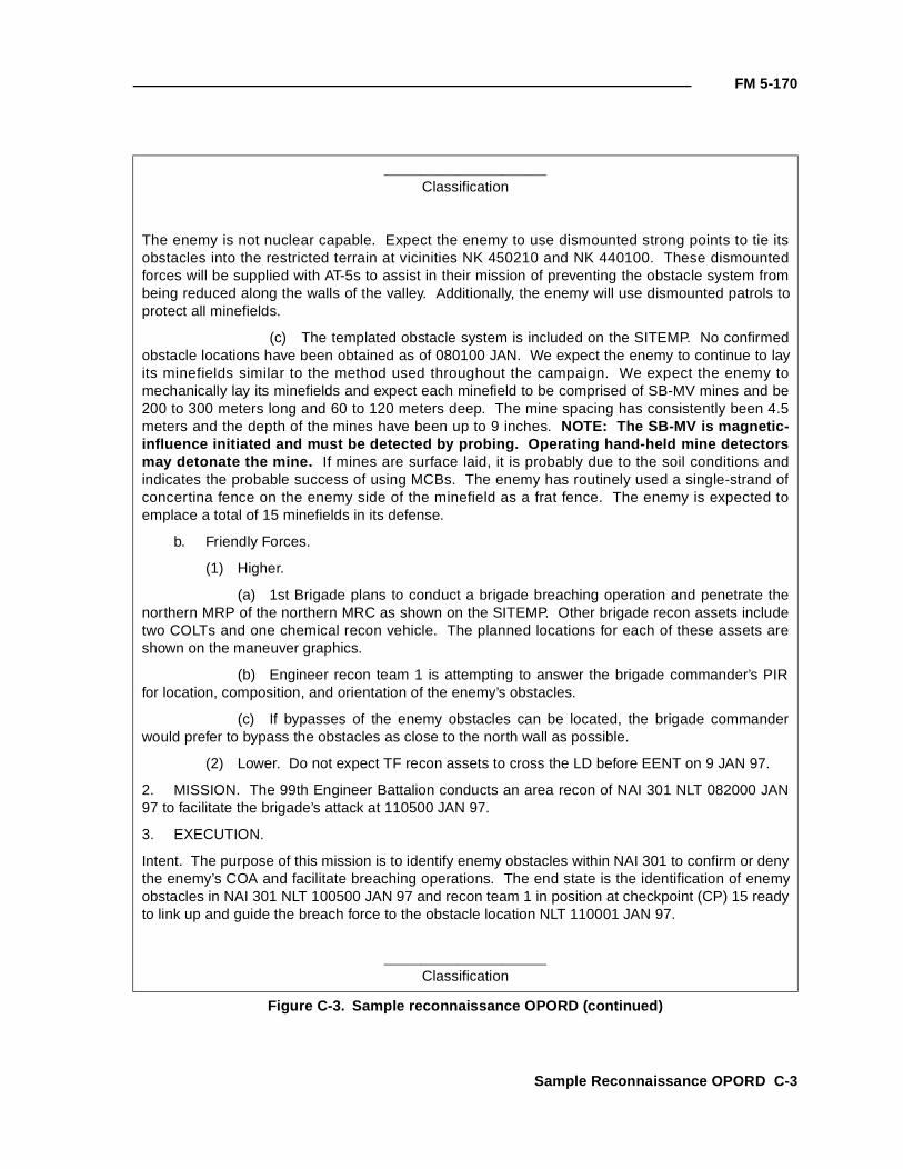
FM 5-170
______________________Classification
The enemy is not nuclear capable. Expect the enemy to use dismounted strong points to tie itsobstacles into the restricted terrain at vicinities NK 450210 and NK 440100. These dismountedforces will be supplied with AT-5s to assist in their mission of preventing the obstacle system frombeing reduced along the walls of the valley. Additionally, the enemy will use dismounted patrols toprotect all minefields.
(c) The templated obstacle system is included on the SITEMP. No confirmedobstacle locations have been obtained as of 080100 JAN. We expect the enemy to continue to layits minefields similar to the method used throughout the campaign. We expect the enemy tomechanically lay its minefields and expect each minefield to be comprised of SB-MV mines and be200 to 300 meters long and 60 to 120 meters deep. The mine spacing has consistently been 4.5meters and the depth of the mines have been up to 9 inches. NOTE: The SB-MV is magnetic-influence initiated and must be detected by probing. Operating hand-held mine detectorsmay detonate the mine. If mines are surface laid, it is probably due to the soil conditions andindicates the probable success of using MCBs. The enemy has routinely used a single-strand ofconcertina fence on the enemy side of the minefield as a frat fence. The enemy is expected toemplace a total of 15 minefields in its defense.
b. Friendly Forces.
(1) Higher.
(a) 1st Brigade plans to conduct a brigade breaching operation and penetrate thenorthern MRP of the northern MRC as shown on the SITEMP. Other brigade recon assets includetwo COLTs and one chemical recon vehicle. The planned locations for each of these assets areshown on the maneuver graphics.
(b) Engineer recon team 1 is attempting to answer the brigade commander’s PIRfor location, composition, and orientation of the enemy’s obstacles.
(c) If bypasses of the enemy obstacles can be located, the brigade commanderwould prefer to bypass the obstacles as close to the north wall as possible.
(2) Lower. Do not expect TF recon assets to cross the LD before EENT on 9 JAN 97.
2. MISSION. The 99th Engineer Battalion conducts an area recon of NAI 301 NLT 082000 JAN97 to facilitate the brigade’s attack at 110500 JAN 97.
3. EXECUTION.
Intent. The purpose of this mission is to identify enemy obstacles within NAI 301 to confirm or denythe enemy’s COA and facilitate breaching operations. The end state is the identification of enemyobstacles in NAI 301 NLT 100500 JAN 97 and recon team 1 in position at checkpoint (CP) 15 readyto link up and guide the breach force to the obstacle location NLT 110001 JAN 97.
______________________Classification
Figure C-3. Sample reconnaissance OPORD (continued)
Sample Reconnaissance OPORD C-3
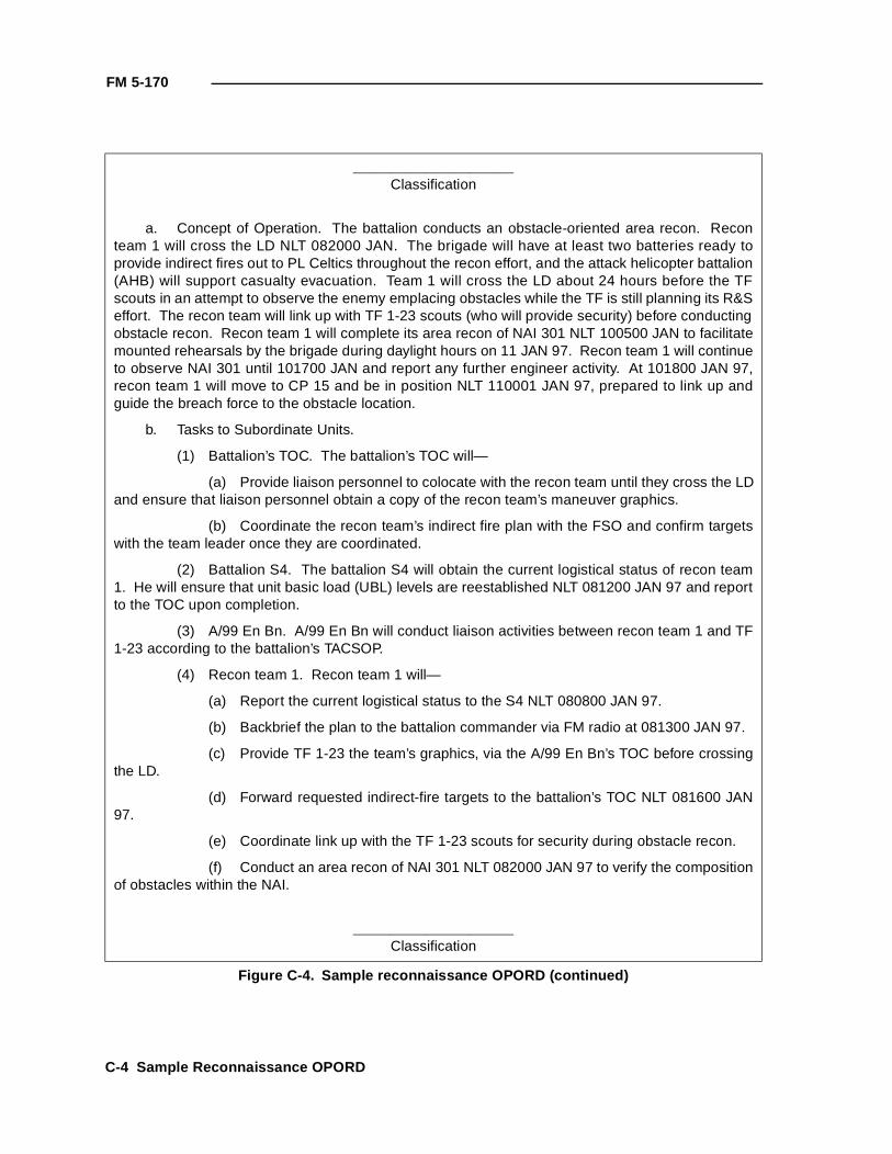
FM 5-170
______________________Classification
a. Concept of Operation. The battalion conducts an obstacle-oriented area recon. Reconteam 1 will cross the LD NLT 082000 JAN. The brigade will have at least two batteries ready toprovide indirect fires out to PL Celtics throughout the recon effort, and the attack helicopter battalion(AHB) will support casualty evacuation. Team 1 will cross the LD about 24 hours before the TFscouts in an attempt to observe the enemy emplacing obstacles while the TF is still planning its R&Seffort. The recon team will link up with TF 1-23 scouts (who will provide security) before conductingobstacle recon. Recon team 1 will complete its area recon of NAI 301 NLT 100500 JAN to facilitatemounted rehearsals by the brigade during daylight hours on 11 JAN 97. Recon team 1 will continueto observe NAI 301 until 101700 JAN and report any further engineer activity. At 101800 JAN 97,recon team 1 will move to CP 15 and be in position NLT 110001 JAN 97, prepared to link up andguide the breach force to the obstacle location.
b. Tasks to Subordinate Units.
(1) Battalion’s TOC. The battalion’s TOC will—
(a) Provide liaison personnel to colocate with the recon team until they cross the LDand ensure that liaison personnel obtain a copy of the recon team’s maneuver graphics.
(b) Coordinate the recon team’s indirect fire plan with the FSO and confirm targetswith the team leader once they are coordinated.
(2) Battalion S4. The battalion S4 will obtain the current logistical status of recon team1. He will ensure that unit basic load (UBL) levels are reestablished NLT 081200 JAN 97 and reportto the TOC upon completion.
(3) A/99 En Bn. A/99 En Bn will conduct liaison activities between recon team 1 and TF1-23 according to the battalion’s TACSOP.
(4) Recon team 1. Recon team 1 will—
(a) Report the current logistical status to the S4 NLT 080800 JAN 97.
(b) Backbrief the plan to the battalion commander via FM radio at 081300 JAN 97.
(c) Provide TF 1-23 the team’s graphics, via the A/99 En Bn’s TOC before crossingthe LD.
(d) Forward requested indirect-fire targets to the battalion’s TOC NLT 081600 JAN97.
(e) Coordinate link up with the TF 1-23 scouts for security during obstacle recon.
(f) Conduct an area recon of NAI 301 NLT 082000 JAN 97 to verify the compositionof obstacles within the NAI.
______________________Classification
Figure C-4. Sample reconnaissance OPORD (continued)
C-4 Sample Reconnaissance OPORD
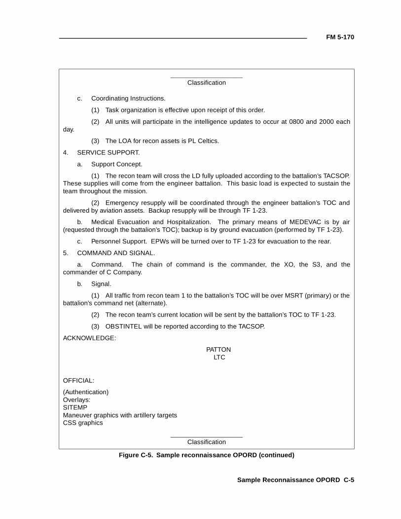
FM 5-170
______________________Classification
c. Coordinating Instructions.
(1) Task organization is effective upon receipt of this order.
(2) All units will participate in the intelligence updates to occur at 0800 and 2000 eachday.
(3) The LOA for recon assets is PL Celtics.
4. SERVICE SUPPORT.
a. Support Concept.
(1) The recon team will cross the LD fully uploaded according to the battalion’s TACSOP.These supplies will come from the engineer battalion. This basic load is expected to sustain theteam throughout the mission.
(2) Emergency resupply will be coordinated through the engineer battalion’s TOC anddelivered by aviation assets. Backup resupply will be through TF 1-23.
b. Medical Evacuation and Hospitalization. The primary means of MEDEVAC is by air(requested through the battalion’s TOC); backup is by ground evacuation (performed by TF 1-23).
c. Personnel Support. EPWs will be turned over to TF 1-23 for evacuation to the rear.
5. COMMAND AND SIGNAL.
a. Command. The chain of command is the commander, the XO, the S3, and thecommander of C Company.
b. Signal.
(1) All traffic from recon team 1 to the battalion’s TOC will be over MSRT (primary) or thebattalion’s command net (alternate).
(2) The recon team’s current location will be sent by the battalion’s TOC to TF 1-23.
(3) OBSTINTEL will be reported according to the TACSOP.
ACKNOWLEDGE:
PATTON LTC
OFFICIAL:
(Authentication)Overlays:SITEMPManeuver graphics with artillery targetsCSS graphics
______________________Classification
Figure C-5. Sample reconnaissance OPORD (continued)
Sample Reconnaissance OPORD C-5

FM 5-170
C-6 Sample Reconnaissance OPORD
Appendix D
Engineer Recon
A general engineer recon gathers engineer information of a broad naturewithin an AO. It considers construction material, resources, and terrainfeatures having engineer applications.
A general engineer recon may be conducted in conjunction with other recons.The Engineer Reconnaissance Report (see Figures D-1 and D-2, pages D-2through D-6) will help ensure that all important information is captured.
The Engineer Reconnaissance Report is used to report items that are notadequately covered by other report forms previously discussed in this manual,but one of significance to engineer activities. The following information isincluded in the report:
• Heading. Self-explanatory.
• Key. The key references the item of the report and its correspondinglocation on the recon overlay. The object’s serial number (or criticalpoint number) is entered in this column.
• Object. Shown by a conventional symbol (see Figure D-3, pages D-7and D-8) or a brief written description.
• Work Estimate. If a work estimate is included as part of the report,enter yes; if not, enter no.
• Additional Remarks. In this column, report the object’s location bygrid coordinates followed by remarks, calculations, and sketches.Make this information as detailed as possible to alleviate the necessityfor an additional recon.
• Authentication Block. This is for the company commander’s signatureblock and signature.
• Work Estimate. The work estimate is on the back of the DA Form1711-R. Each work estimate is keyed by a serial or critical pointnumber to the appropriate object on the reverse side of the form. Onlythose columns that are appropriate need be completed. Drawadditional sketches when necessary (see Figure D-2).
Engineer Recon D-1
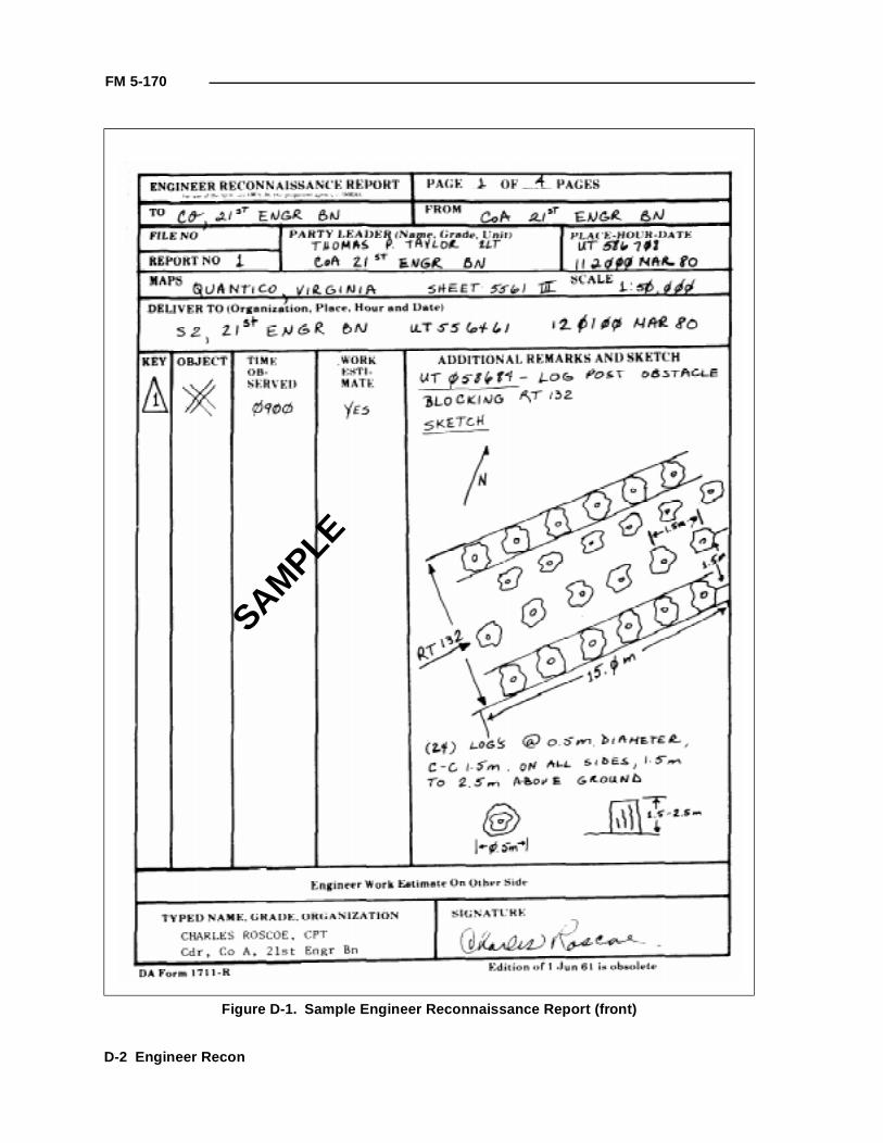
FM 5-170
Figure D-1. Sample Engineer Reconnaissance Report (front)
SAMPLE
D-2 Engineer Recon
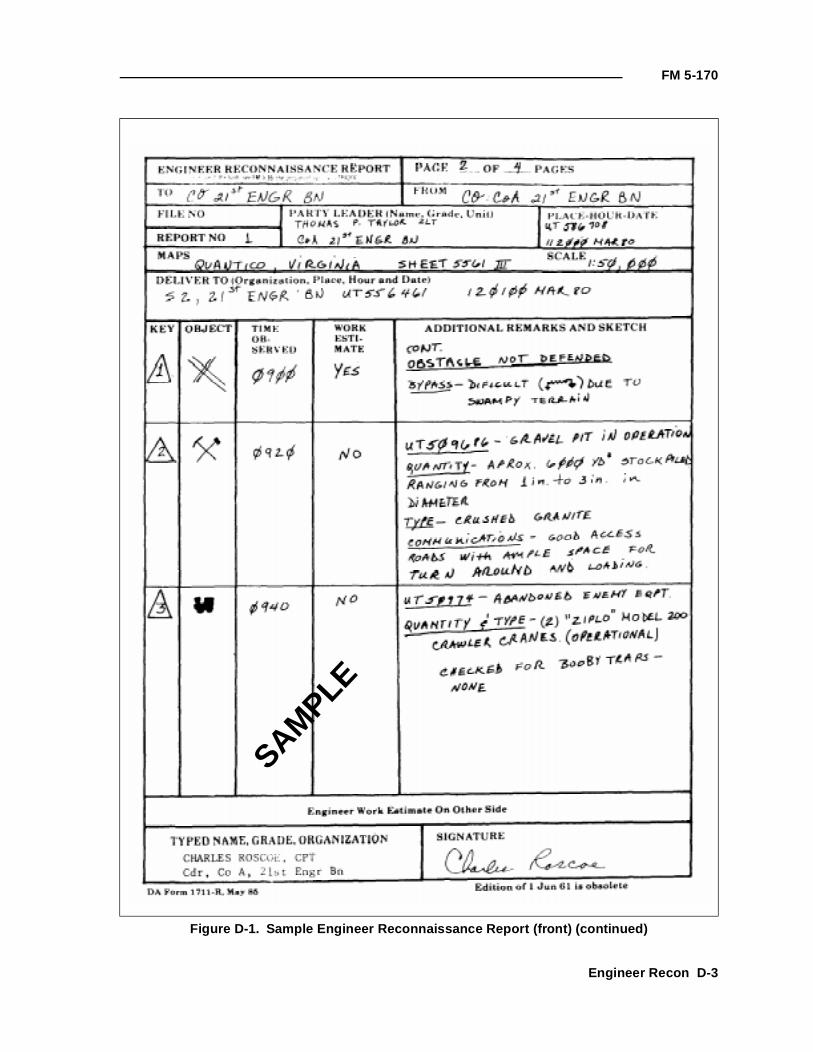
FM 5-170
Figure D-1. Sample Engineer Reconnaissance Report (front) (continued)
SAMPLE
Engineer Recon D-3
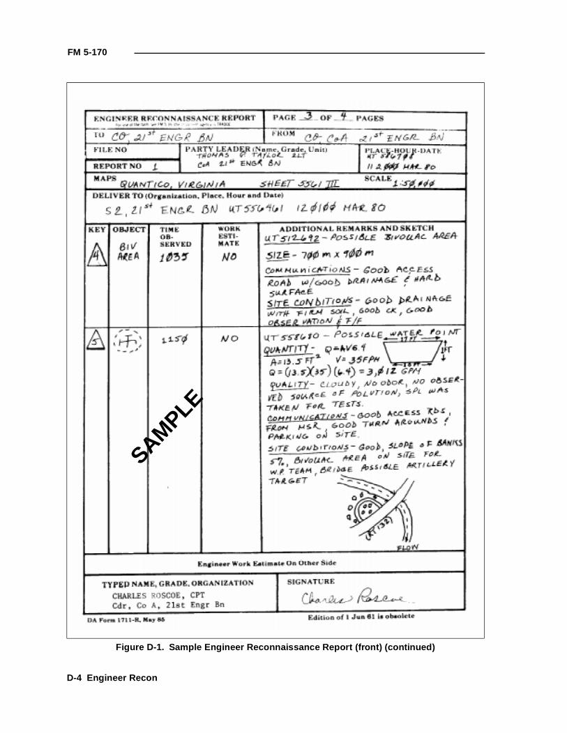
FM 5-170
Figure D-1. Sample Engineer Reconnaissance Report (front) (continued)
SAMPLE
D-4 Engineer Recon
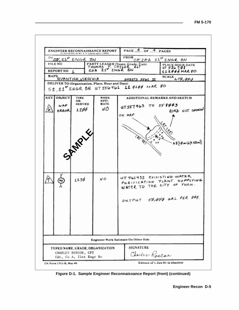
FM 5-170
Figure D-1. Sample Engineer Reconnaissance Report (front) (continued)
SAMPLE
Engineer Recon D-5
FM 5-170
Figure D-2. Sample Engineer Reconnaissance Report (back)
SAM
PLE
D-6 Engineer Recon
FM 5-170
Figure D-3. Engineer resource symbols
Sawmill
Lumber yard
Stone
Aggregate (including gravel and slag)
Sand
Cement concrete products
Stocks of bricks and other clay products
Iron and steel stock
Wire stock
Paint
Glass stock
Gypsum and lime products
Asphalt and bituminous stock
Stocks of roof covering
Engineer Recon D-7
FM 5-170
Figure D-3. Engineer resource symbols (continued)
Building hardware
Industrial gases
Cordage, nets, yarns
Civil-engineering firms
Building contractors
Factories
Factory symbol plus plant product
Mobile, heavy-construction equipment
Forestry equipment
Quarrying equipment
Handling and transportation equipment storage
Powered hand tools
Water-purification equipment (civilian)
Electrical supply equipment
Steel-rolling mills and foundries
Engineering workshops
Established military water point
Possible military water point
D-8 Engineer Recon
Appendix E
Signs
Procedures for posting military routes are standardized for the US andAllied Nations (STANAG 2027). However, this system may be integratedinto other road-sign systems in accordance with military requirements.
MILITARY ROUTE SIGNS
There are three general types of standard route signs—hazard, regulatory,and guide. Table E-1 lists the way each type may be used. The size of thesesigns is not prescribed; they must be large enough to be easily read under poorlighting conditions. Exceptions to this rule are bridge classification signs forwhich dimensions are specific. As a guide, signs for civil international roaduse are usually not less than 16 inches square.
Table E-1. Typical hazard, regulatory, and guide signs
Application
TypeHazard Regulatory Guide
Advance warning of stop signs and traffic signals
No entry Detour
Changes in road width One way Detour begins
Crossroad Parking restrictions Detour ends
CurvesSpecific regulations for vehicles
Directions
Danger or hazard Speed limit Distances
Dangerous corner Stop Information to help driver
Dips Bridge classification Locations
Junction T Route number
Junction Y
Level railroad crossing, advance warning
Men working
Railroad crossing
Road construction repairs
Road narrows
Slippery road
Steep grades
Steep hill
Turns
This appendix implements STANAGs 2027 and 2154.
Signs E-1
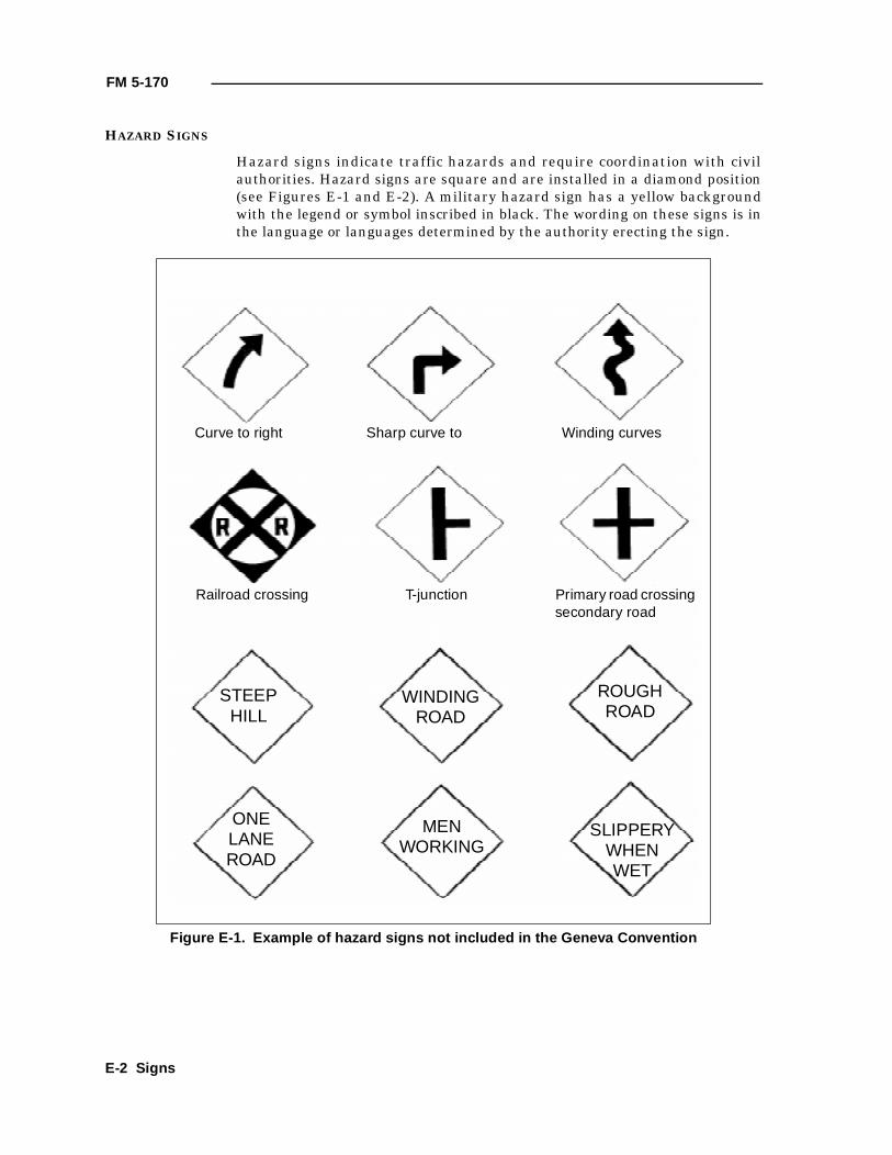
FM 5-170
HAZARD SIGNS
Hazard signs indicate traffic hazards and require coordination with civilauthorities. Hazard signs are square and are installed in a diamond position(see Figures E-1 and E-2). A military hazard sign has a yellow backgroundwith the legend or symbol inscribed in black. The wording on these signs is inthe language or languages determined by the authority erecting the sign.
Figure E-1. Example of hazard signs not included in the Geneva Convention
Curve to right Sharp curve to Winding curves
Railroad crossing T-junction Primary road crossing secondary road
STEEPHILL
WINDINGROAD
ROUGHROAD
ONELANEROAD
MENWORKING
SLIPPERYWHENWET
E-2 Signs
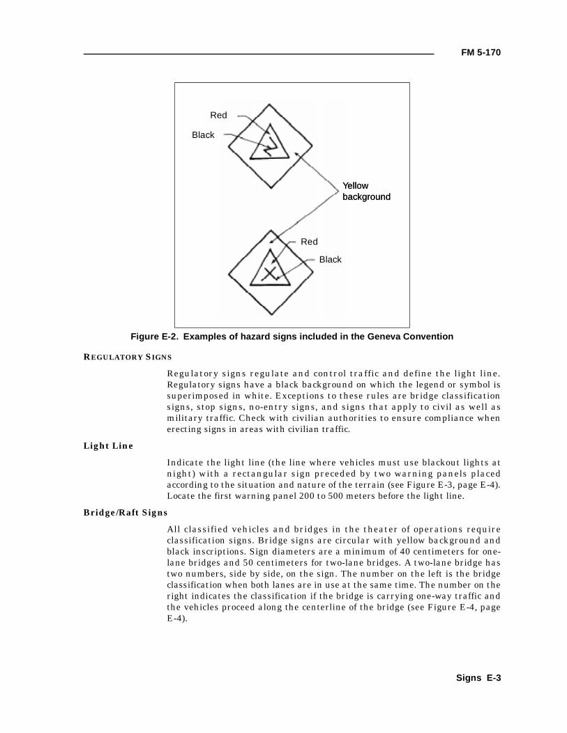
FM 5-170
REGULATORY SIGNS
Regulatory signs regulate and control traffic and define the light line.Regulatory signs have a black background on which the legend or symbol issuperimposed in white. Exceptions to these rules are bridge classificationsigns, stop signs, no-entry signs, and signs that apply to civil as well asmilitary traffic. Check with civilian authorities to ensure compliance whenerecting signs in areas with civilian traffic.
Light Line
Indicate the light line (the line where vehicles must use blackout lights atnight) with a rectangular sign preceded by two warning panels placedaccording to the situation and nature of the terrain (see Figure E-3, page E-4).Locate the first warning panel 200 to 500 meters before the light line.
Bridge/Raft Signs
All classified vehicles and bridges in the theater of operations requireclassification signs. Bridge signs are circular with yellow background andblack inscriptions. Sign diameters are a minimum of 40 centimeters for one-lane bridges and 50 centimeters for two-lane bridges. A two-lane bridge hastwo numbers, side by side, on the sign. The number on the left is the bridgeclassification when both lanes are in use at the same time. The number on theright indicates the classification if the bridge is carrying one-way traffic andthe vehicles proceed along the centerline of the bridge (see Figure E-4, pageE-4).
Figure E-2. Examples of hazard signs included in the Geneva Convention
Yellow backgroundYellow background
Red
Red
Black
Black
Signs E-3
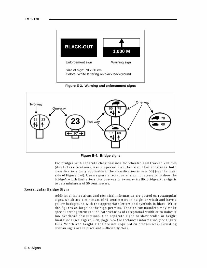
FM 5-170
For bridges with separate classifications for wheeled and tracked vehicles(dual classification), use a special circular sign that indicates bothclassifications (only applicable if the classification is over 50) (see the rightside of Figure E-4). Use a separate rectangular sign, if necessary, to show thebridge’s width limitations. For one-way or two-way traffic bridges, the sign isto be a minimum of 50 centimeters.
Rectangular Bridge Signs
Additional instructions and technical information are posted on rectangularsigns, which are a minimum of 41 centimeters in height or width and have ayellow background with the appropriate letters and symbols in black. Writethe figures as large as the sign permits. Theater commanders may makespecial arrangements to indicate vehicles of exceptional width or to indicatelow overhead obstructions. Use separate signs to show width or heightlimitations (see Figure 5-38, page 5-52) or technical information (see FigureE-5). Width and height signs are not required on bridges where existingcivilian signs are in place and sufficiently clear.
Figure E-3. Warning and enforcement signs
Figure E-4. Bridge signs
BLACK-OUT1,000 M
Enforcement sign Warning sign
Size of sign: 70 x 60 cmColors: White lettering on black background
10'
66 78
78
68
One-way
23 Two-way
One-wayTwo-way
18 23
57 68
E-4 Signs
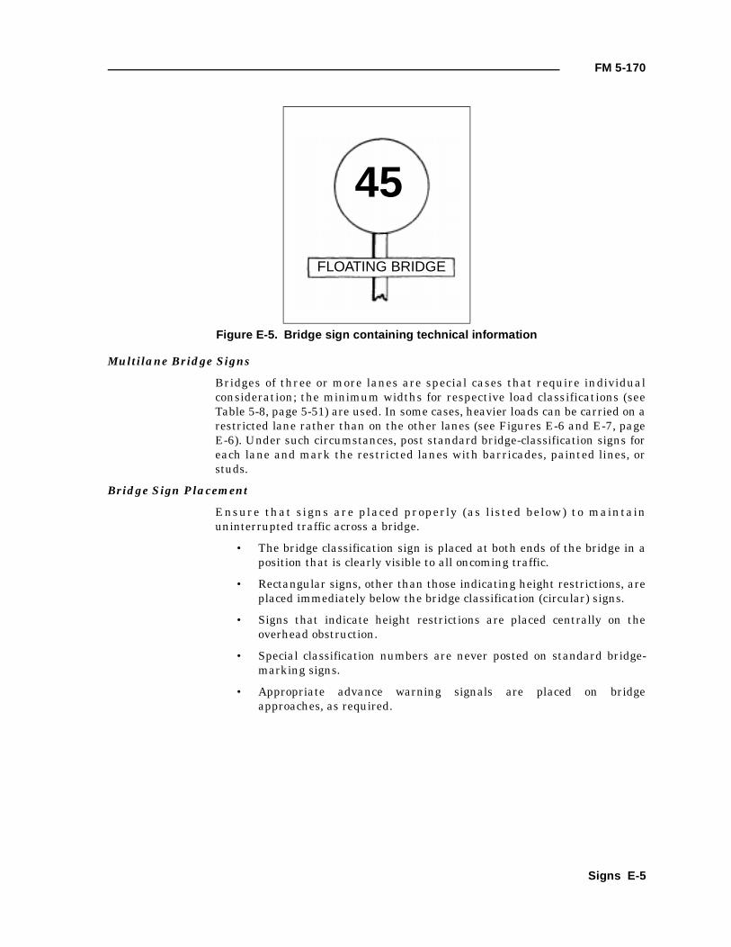
FM 5-170
Multilane Bridge Signs
Bridges of three or more lanes are special cases that require individualconsideration; the minimum widths for respective load classifications (seeTable 5-8, page 5-51) are used. In some cases, heavier loads can be carried on arestricted lane rather than on the other lanes (see Figures E-6 and E-7, pageE-6). Under such circumstances, post standard bridge-classification signs foreach lane and mark the restricted lanes with barricades, painted lines, orstuds.
Bridge Sign Placement
Ensure that signs are placed properly (as listed below) to maintainuninterrupted traffic across a bridge.
• The bridge classification sign is placed at both ends of the bridge in aposition that is clearly visible to all oncoming traffic.
• Rectangular signs, other than those indicating height restrictions, areplaced immediately below the bridge classification (circular) signs.
• Signs that indicate height restrictions are placed centrally on theoverhead obstruction.
• Special classification numbers are never posted on standard bridge-marking signs.
• Appropriate advance warning signals are placed on bridgeapproaches, as required.
Figure E-5. Bridge sign containing technical information
45
FLOATING BRIDGE
Signs E-5
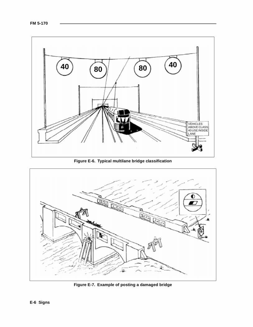
FM 5-170
Figure E-6. Typical multilane bridge classification
Figure E-7. Example of posting a damaged bridge
40 4080 80
VEHICLES ABOVE CLASS 40 USE INSIDE LANE
E-6 Signs
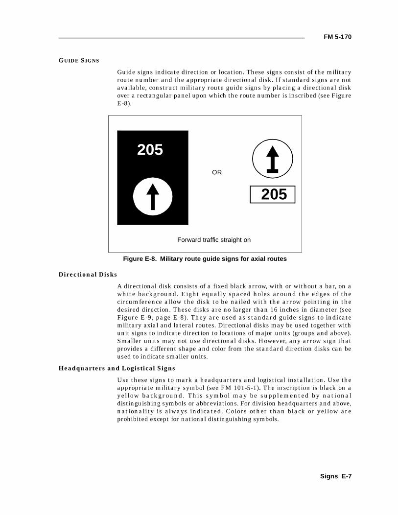
FM 5-170
GUIDE SIGNS
Guide signs indicate direction or location. These signs consist of the militaryroute number and the appropriate directional disk. If standard signs are notavailable, construct military route guide signs by placing a directional diskover a rectangular panel upon which the route number is inscribed (see FigureE-8).
Directional Disks
A directional disk consists of a fixed black arrow, with or without a bar, on awhite background. Eight equally spaced holes around the edges of thecircumference allow the disk to be nailed with the arrow pointing in thedesired direction. These disks are no larger than 16 inches in diameter (seeFigure E-9, page E-8). They are used as standard guide signs to indicatemilitary axial and lateral routes. Directional disks may be used together withunit signs to indicate direction to locations of major units (groups and above).Smaller units may not use directional disks. However, any arrow sign thatprovides a different shape and color from the standard direction disks can beused to indicate smaller units.
Headquarters and Logistical Signs
Use these signs to mark a headquarters and logistical installation. Use theappropriate military symbol (see FM 101-5-1). The inscription is black on ayellow background. This symbol may be supplemented by nationaldistinguishing symbols or abbreviations. For division headquarters and above,nationality is always indicated. Colors other than black or yellow areprohibited except for national distinguishing symbols.
Figure E-8. Military route guide signs for axial routes
205
205
OR
Forward traffic straight on
Signs E-7
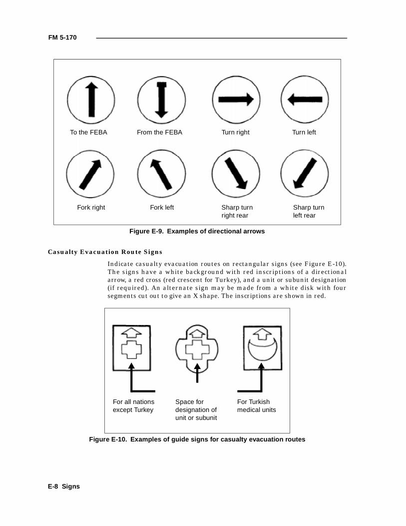
FM 5-170
Casualty Evacuation Route Signs
Indicate casualty evacuation routes on rectangular signs (see Figure E-10).The signs have a white background with red inscriptions of a directionalarrow, a red cross (red crescent for Turkey), and a unit or subunit designation(if required). An alternate sign may be made from a white disk with foursegments cut out to give an X shape. The inscriptions are shown in red.
Figure E-9. Examples of directional arrows
Figure E-10. Examples of guide signs for casualty evacuation routes
To the FEBA From the FEBA Turn right Turn left
Fork right Fork left Sharp turn right rear
Sharp turn left rear
For all nations except Turkey
Space for designation of unit or subunit
For Turkish medical units
E-8 Signs
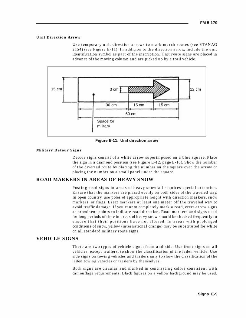
FM 5-170
Unit Direction Arrow
Use temporary unit direction arrows to mark march routes (see STANAG2154) (see Figure E-11). In addition to the direction arrow, include the unitidentification symbol as part of the inscription. Unit route signs are placed inadvance of the moving column and are picked up by a trail vehicle.
Military Detour Signs
Detour signs consist of a white arrow superimposed on a blue square. Placethe sign in a diamond position (see Figure E-12, page E-10). Show the numberof the diverted route by placing the number on the square over the arrow orplacing the number on a small panel under the square.
ROAD MARKERS IN AREAS OF HEAVY SNOW
Posting road signs in areas of heavy snowfall requires special attention.Ensure that the markers are placed evenly on both sides of the traveled way.In open country, use poles of appropriate height with direction markers, snowmarkers, or flags. Erect markers at least one meter off the traveled way toavoid traffic damage. If you cannot completely mark a road, erect arrow signsat prominent points to indicate road direction. Road markers and signs usedfor long periods of time in areas of heavy snow should be checked frequently toensure that their positions have not altered. In areas with prolongedconditions of snow, yellow (international orange) may be substituted for whiteon all standard military route signs.
VEHICLE SIGNS
There are two types of vehicle signs: front and side. Use front signs on allvehicles, except trailers, to show the classification of the laden vehicle. Useside signs on towing vehicles and trailers only to show the classification of theladen towing vehicles or trailers by themselves.
Both signs are circular and marked in contrasting colors consistent withcamouflage requirements. Black figures on a yellow background may be used.
Figure E-11. Unit direction arrow
15 cm 12 cm3 cm
30 cm 15 cm 15 cm
60 cm
Space for military
Signs E-9
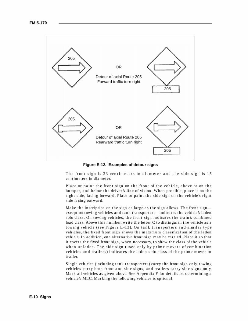
FM 5-170
The front sign is 23 centimeters in diameter and the side sign is 15centimeters in diameter.
Place or paint the front sign on the front of the vehicle, above or on thebumper, and below the driver’s line of vision. When possible, place it on theright side, facing forward. Place or paint the side sign on the vehicle’s rightside facing outward.
Make the inscription on the sign as large as the sign allows. The front sign—except on towing vehicles and tank transporters—indicates the vehicle’s ladensolo class. On towing vehicles, the front sign indicates the train’s combinedload class. Above this number, write the letter C to distinguish the vehicle as atowing vehicle (see Figure E-13). On tank transporters and similar typevehicles, the fixed front sign shows the maximum classification of the ladenvehicle. In addition, one alternative front sign may be carried. Place it so thatit covers the fixed front sign, when necessary, to show the class of the vehiclewhen unladen. The side sign (used only by prime movers of combinationvehicles and trailers) indicates the laden solo class of the prime mover ortrailer.
Single vehicles (including tank transporters) carry the front sign only, towingvehicles carry both front and side signs, and trailers carry side signs only.Mark all vehicles as given above. See Appendix F for details on determining avehicle’s MLC. Marking the following vehicles is optional:
Figure E-12. Examples of detour signs
OR
Detour of axial Route 205Forward traffic turn right
OR
Detour of axial Route 205Rearward traffic turn right
205
205
205
205
E-10 Signs
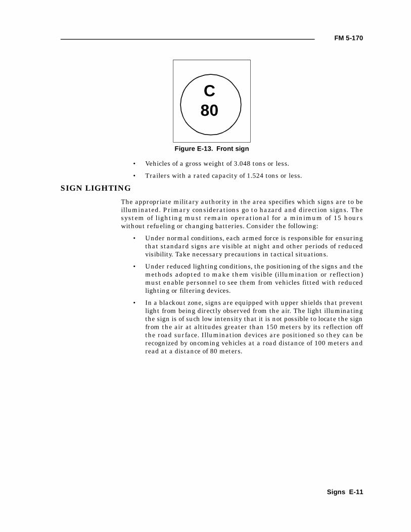
FM 5-170
• Vehicles of a gross weight of 3.048 tons or less.
• Trailers with a rated capacity of 1.524 tons or less.
SIGN LIGHTING
The appropriate military authority in the area specifies which signs are to beilluminated. Primary considerations go to hazard and direction signs. Thesystem of lighting must remain operational for a minimum of 15 hourswithout refueling or changing batteries. Consider the following:
• Under normal conditions, each armed force is responsible for ensuringthat standard signs are visible at night and other periods of reducedvisibility. Take necessary precautions in tactical situations.
• Under reduced lighting conditions, the positioning of the signs and themethods adopted to make them visible (illumination or reflection)must enable personnel to see them from vehicles fitted with reducedlighting or filtering devices.
• In a blackout zone, signs are equipped with upper shields that preventlight from being directly observed from the air. The light illuminatingthe sign is of such low intensity that it is not possible to locate the signfrom the air at altitudes greater than 150 meters by its reflection offthe road surface. Illumination devices are positioned so they can berecognized by oncoming vehicles at a road distance of 100 meters andread at a distance of 80 meters.
Figure E-13. Front sign
C80
Signs E-11

FM 5-170
E-12 Signs
Appendix F
Military Load Classifications
The basis for MLC is the effect (load, vehicle speed, tire width, and soforth) a vehicle has on a bridge when crossing. Heavy loads, such asartillery and tanks, make vehicle classification a very important factorwhen determining what can travel down a route.
REQUIREMENT FOR CLASSIFICATION NUMBERS
Classification numbers are mandatory for all self-propelled vehicles having atotal weight of 3 tons or more, as well as all trailers with a payload of 1 1/2tons or greater (see STANAGs 2010 and 2021). Trailers with a rated capacityof less than 1 1/2 tons are usually combined with their towing vehicles forclassification. During the classification process, vehicles are divided and intotwo further groups—those with trailers (vehicle combination class number[CCN]) and those without (single vehicle classification number)—andcalculated accordingly.
PROCEDURES FOR VEHICLE CLASSIFICATION
The actual mathematical computation of a vehicle’s MLC is beyond thecapability of route recon teams. However, temporary procedures are describedbelow. MLC information is found in the vehicle’s TM or on the dash’s dataplate.
TEMPORARY PROCEDURE FOR VEHICLE CLASSIFICATION
When a single vehicle tows another vehicle at a distance less than 30.5 metersand the vehicles are not designed to operate as one unit, the temporary vehicleMLC number may be assigned to this combination. The classification numberassigned is nine-tenths the sum of the normal vehicle classification numbers ifthe total of both classifications is less than 60. If the sum of the two militaryclassification numbers is 60 or over, then the total becomes the MLC numberfor the nonstandard combination.
CCN = 0.9 (A + B) if A + B < 60CCN = A + B if A + B > 60
where—A = class of first vehicleB = class of second vehicle
EXPEDIENT PROCEDURE FOR WHEELED-VEHICLE CLASSIFICATION
It will be necessary, on occasion, to classify a vehicle in the field. Simplyobserve and compare the unclassified vehicle to a vehicle that is similar.Compare the axle loads, gross weight, and dimensions of the unclassifiedvehicle with those of a similar classification.
Military Load Classifications F-1
FM 5-170
Example: The expedient classification for a wheeled vehicle is estimated tobe 85 percent of its total weight. Therefore, you must determine the vehicle’sgross weight. Multiply the air pressure in the tires (in pounds per square inch[psi]) by the total area (in square inches) of the tires in contact with theground. If a gage is not available, use 75 psi as an average value. This yieldsan approximate weight of the vehicle in pounds. Convert this figure to tonsand find 85 percent of the weight in tons. This resulting figure is the expedientclassification.
EXPEDIENT PROCEDURE FOR TRACKED-VEHICLE CLASSIFICATION
Tracked vehicles weigh about one ton per square foot of track contact with theground. By determining the area of track in contact with the ground, thevehicle’s gross weight can be assigned. In the case of vehicles that weigh afraction over whole tonnage, the next higher classification number is assigned.
F-2 Military Load Classifications
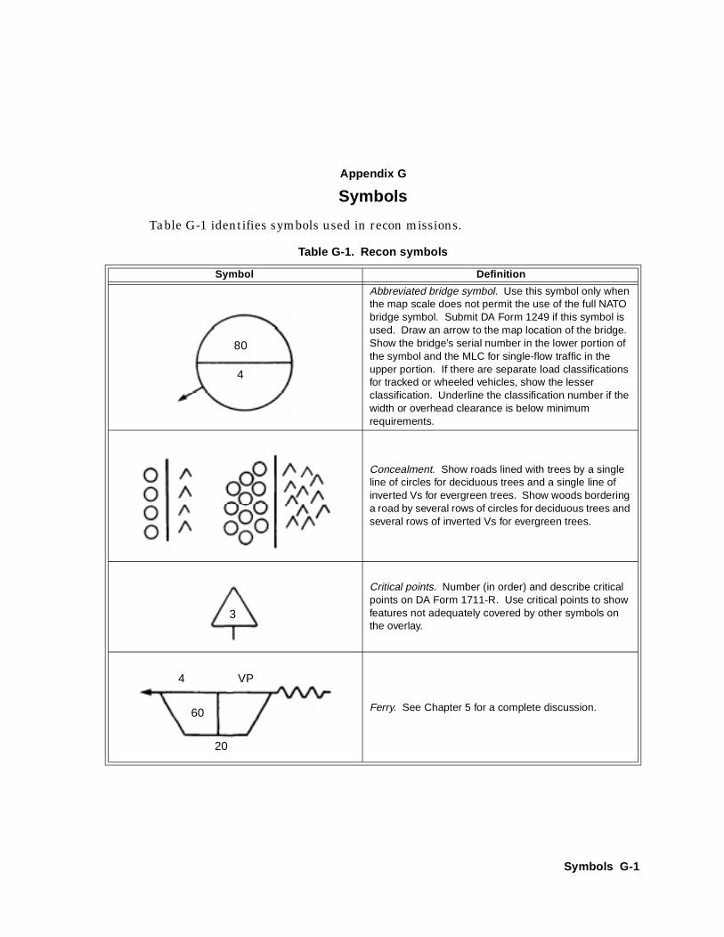
Appendix G
Symbols
Table G-1 identifies symbols used in recon missions.
Table G-1. Recon symbols
Symbol Definition
Abbreviated bridge symbol. Use this symbol only when the map scale does not permit the use of the full NATO bridge symbol. Submit DA Form 1249 if this symbol is used. Draw an arrow to the map location of the bridge. Show the bridge’s serial number in the lower portion of the symbol and the MLC for single-flow traffic in the upper portion. If there are separate load classifications for tracked or wheeled vehicles, show the lesser classification. Underline the classification number if the width or overhead clearance is below minimum requirements.
Concealment. Show roads lined with trees by a single line of circles for deciduous trees and a single line of inverted Vs for evergreen trees. Show woods bordering a road by several rows of circles for deciduous trees and several rows of inverted Vs for evergreen trees.
Critical points. Number (in order) and describe critical points on DA Form 1711-R. Use critical points to show features not adequately covered by other symbols on the overlay.
Ferry. See Chapter 5 for a complete discussion.
80
4
3
4 VP
60
20
Symbols G-1
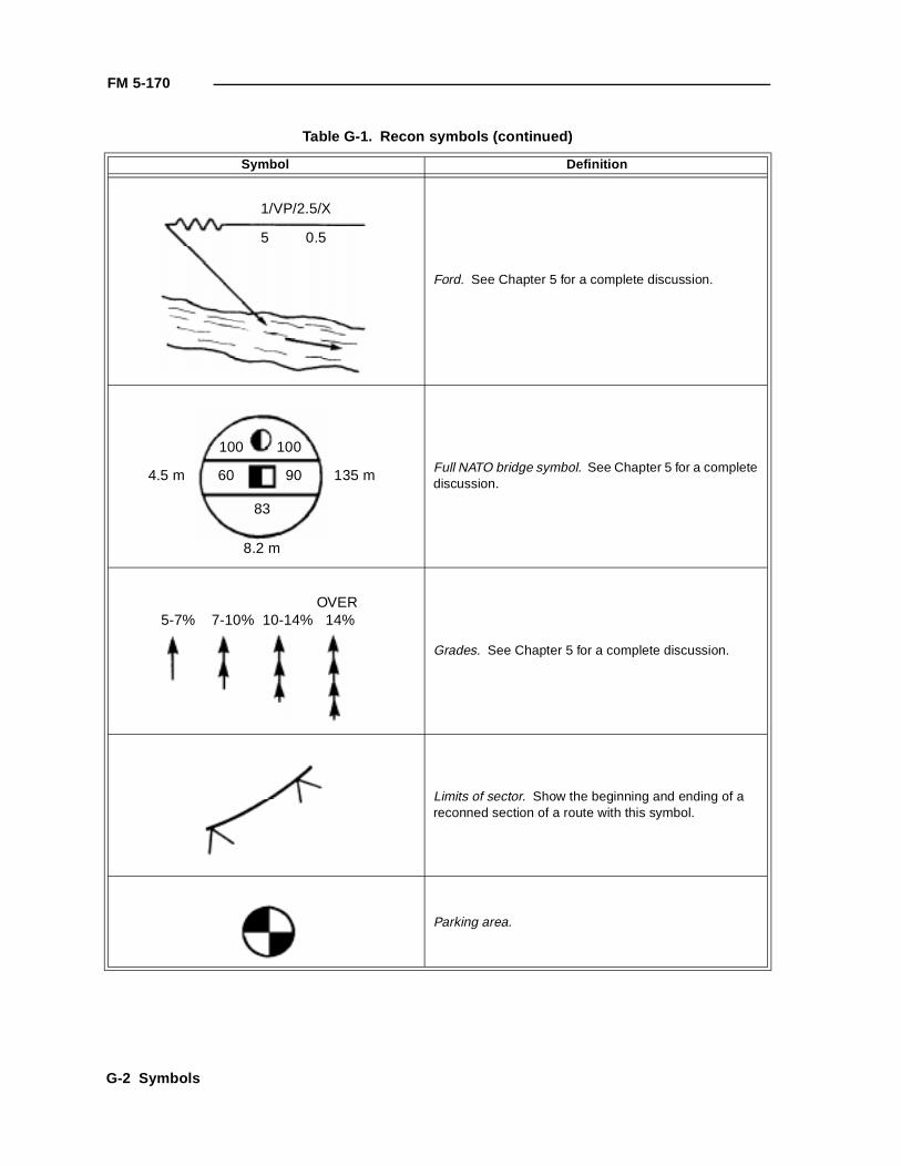
FM 5-170
Ford. See Chapter 5 for a complete discussion.
Full NATO bridge symbol. See Chapter 5 for a complete discussion.
Grades. See Chapter 5 for a complete discussion.
Limits of sector. Show the beginning and ending of a reconned section of a route with this symbol.
Parking area.
Table G-1. Recon symbols (continued)
Symbol Definition
1/VP/2.5/X
5 0.5
100 100
60 90
83
4.5 m 135 m
8.2 m
OVER 5-7% 7-10% 10-14% 14%
G-2 Symbols
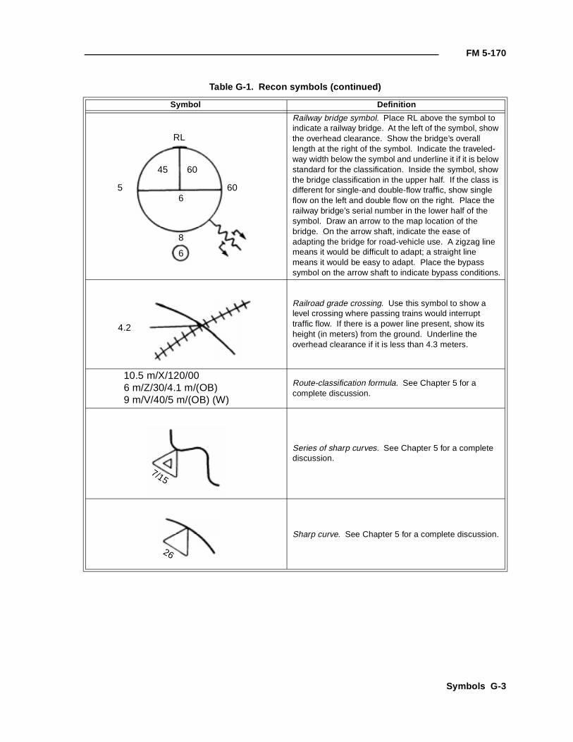
FM 5-170
Railway bridge symbol. Place RL above the symbol to indicate a railway bridge. At the left of the symbol, show the overhead clearance. Show the bridge’s overall length at the right of the symbol. Indicate the traveled-way width below the symbol and underline it if it is below standard for the classification. Inside the symbol, show the bridge classification in the upper half. If the class is different for single-and double-flow traffic, show single flow on the left and double flow on the right. Place the railway bridge’s serial number in the lower half of the symbol. Draw an arrow to the map location of the bridge. On the arrow shaft, indicate the ease of adapting the bridge for road-vehicle use. A zigzag line means it would be difficult to adapt; a straight line means it would be easy to adapt. Place the bypass symbol on the arrow shaft to indicate bypass conditions.
Railroad grade crossing. Use this symbol to show a level crossing where passing trains would interrupt traffic flow. If there is a power line present, show its height (in meters) from the ground. Underline the overhead clearance if it is less than 4.3 meters.
10.5 m/X/120/006 m/Z/30/4.1 m/(OB)9 m/V/40/5 m/(OB) (W)
Route-classification formula. See Chapter 5 for a complete discussion.
Series of sharp curves. See Chapter 5 for a complete discussion.
Sharp curve. See Chapter 5 for a complete discussion.
Table G-1. Recon symbols (continued)
Symbol Definition
RL
45 60
5 606
8
6
4.2
7/15
26
Symbols G-3
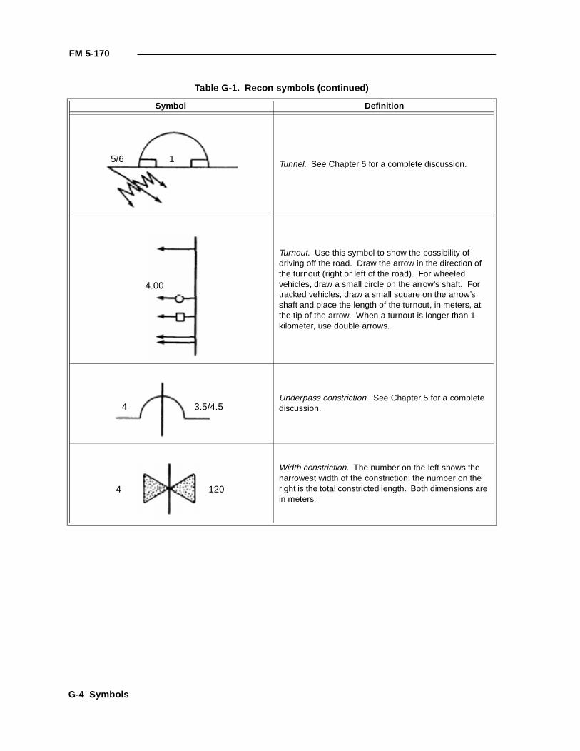
FM 5-170
Tunnel. See Chapter 5 for a complete discussion.
Turnout. Use this symbol to show the possibility of driving off the road. Draw the arrow in the direction of the turnout (right or left of the road). For wheeled vehicles, draw a small circle on the arrow’s shaft. For tracked vehicles, draw a small square on the arrow’s shaft and place the length of the turnout, in meters, at the tip of the arrow. When a turnout is longer than 1 kilometer, use double arrows.
Underpass constriction. See Chapter 5 for a complete discussion.
Width constriction. The number on the left shows the narrowest width of the constriction; the number on the right is the total constricted length. Both dimensions are in meters.
Table G-1. Recon symbols (continued)
Symbol Definition
15/6
4.00
4 3.5/4.5
1204
G-4 Symbols
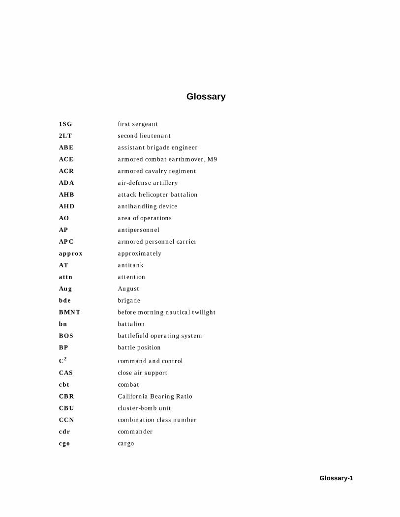
Glossary
1SG first sergeant
2LT second lieutenant
ABE assistant brigade engineer
ACE armored combat earthmover, M9
ACR armored cavalry regiment
ADA air-defense artillery
AHB attack helicopter battalion
AHD antihandling device
AO area of operations
AP antipersonnel
APC armored personnel carrier
approx approximately
AT antitank
attn attention
Aug August
bde brigade
BMNT before morning nautical twilight
bn battalion
BOS battlefield operating system
BP battle position
C2 command and control
CAS close air support
cbt combat
CBR California Bearing Ratio
CBU cluster-bomb unit
CCN combination class number
cdr commander
cgo cargo
Glossary-1

FM 5-170
CL centerline
cm centimeter(s)
co company
COA course of action
COLT combat observation and lazing team
CP checkpoint
CPT captain
CS combat support
CSOP combat security outpost
CSS combat service support
cy cubic yard
DA Department of the Army
DEUCE Deployable Universal Combat Earthmover
DPICM dual-purpose improved conventional munitions
DS direct support
DST decision-support template
DTG date-time group
EA engagement area
EENT end evening nautical twilight
eff effective
EN engineer
eng engineer
engr engineer
EPLRS Enhanced Position Location Reporting System
EPW enemy prisoner of war
equip equipment
FA field artillery
FAC forward air controller
FDC fire-direction center
FEBA forward edge of the battle area
FIST fire-support team
FM field manual
FM frequency modulated
FRAGO fragmentary order
Glossary-2
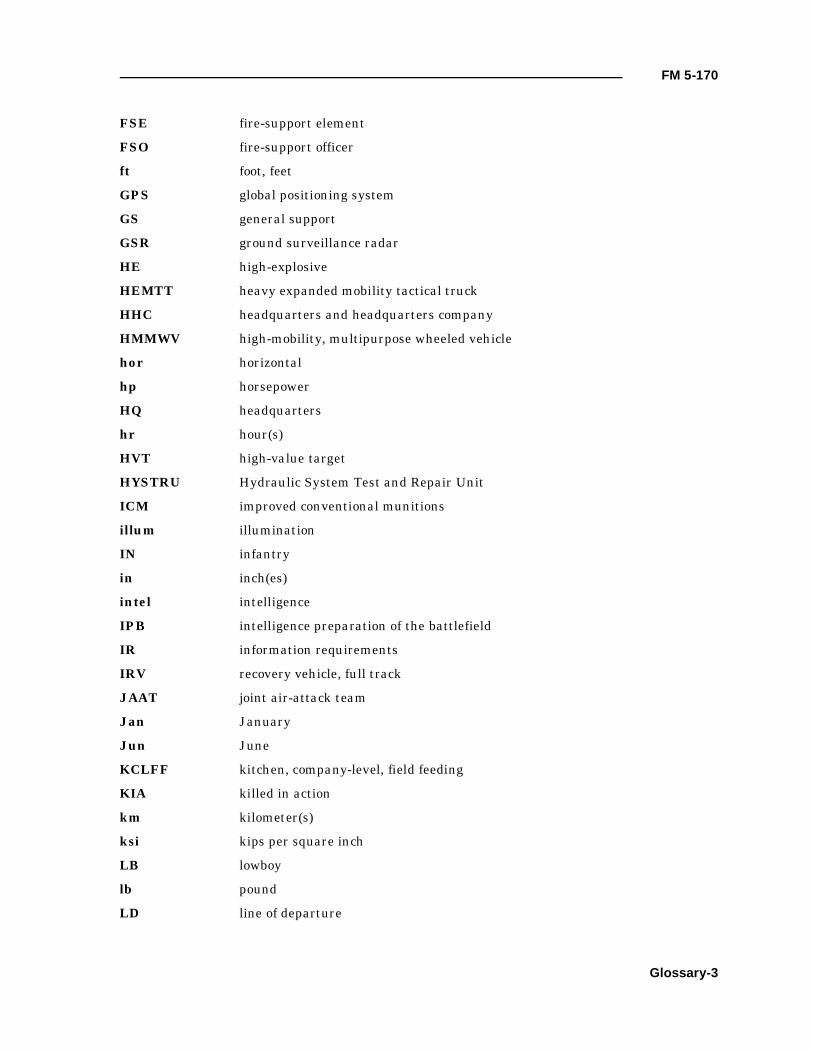
FM 5-170
FSE fire-support element
FSO fire-support officer
ft foot, feet
GPS global positioning system
GS general support
GSR ground surveillance radar
HE high-explosive
HEMTT heavy expanded mobility tactical truck
HHC headquarters and headquarters company
HMMWV high-mobility, multipurpose wheeled vehicle
hor horizontal
hp horsepower
HQ headquarters
hr hour(s)
HVT high-value target
HYSTRU Hydraulic System Test and Repair Unit
ICM improved conventional munitions
illum illumination
IN infantry
in inch(es)
intel intelligence
IPB intelligence preparation of the battlefield
IR information requirements
IRV recovery vehicle, full track
JAAT joint air-attack team
Jan January
Jun June
KCLFF kitchen, company-level, field feeding
KIA killed in action
km kilometer(s)
ksi kips per square inch
LB lowboy
lb pound
LD line of departure
Glossary-3
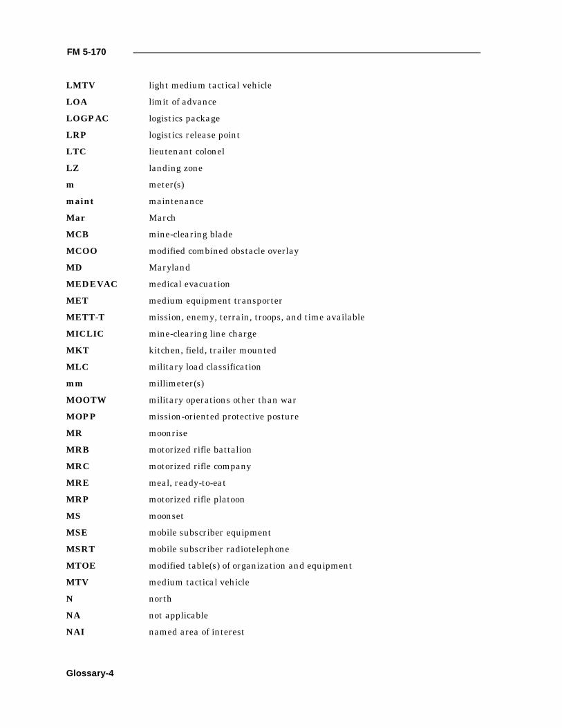
FM 5-170
LMTV light medium tactical vehicle
LOA limit of advance
LOGPAC logistics package
LRP logistics release point
LTC lieutenant colonel
LZ landing zone
m meter(s)
maint maintenance
Mar March
MCB mine-clearing blade
MCOO modified combined obstacle overlay
MD Maryland
MEDEVAC medical evacuation
MET medium equipment transporter
METT-T mission, enemy, terrain, troops, and time available
MICLIC mine-clearing line charge
MKT kitchen, field, trailer mounted
MLC military load classification
mm millimeter(s)
MOOTW military operations other than war
MOPP mission-oriented protective posture
MR moonrise
MRB motorized rifle battalion
MRC motorized rifle company
MRE meal, ready-to-eat
MRP motorized rifle platoon
MS moonset
MSE mobile subscriber equipment
MSRT mobile subscriber radiotelephone
MTOE modified table(s) of organization and equipment
MTV medium tactical vehicle
N north
NA not applicable
NAI named area of interest
Glossary-4
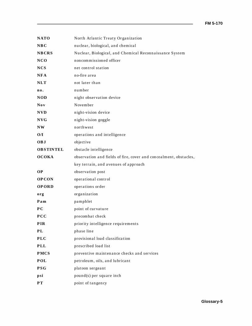
FM 5-170
NATO North Atlantic Treaty Organization
NBC nuclear, biological, and chemical
NBCRS Nuclear, Biological, and Chemical Reconnaissance System
NCO noncommissioned officer
NCS net control station
NFA no-fire area
NLT not later than
no. number
NOD night observation device
Nov November
NVD night-vision device
NVG night-vision goggle
NW northwest
O/I operations and intelligence
OBJ objective
OBSTINTEL obstacle intelligence
OCOKA observation and fields of fire, cover and concealment, obstacles,
key terrain, and avenues of approach
OP observation post
OPCON operational control
OPORD operations order
org organization
Pam pamphlet
PC point of curvature
PCC precombat check
PIR priority intelligence requirements
PL phase line
PLC provisional load classification
PLL prescribed load list
PMCS preventive maintenance checks and services
POL petroleum, oils, and lubricant
PSG platoon sergeant
psi pound(s) per square inch
PT point of tangency
Glossary-5
FM 5-170
R&S reconnaissance and surveillance
RP release point
rpm rounds per minute
RR railroad
S2 Intelligence Officer (US Army)
S3 Operations and Training Officer (US Army)
S4 Supply Officer (US Army)
SAW squad automatic weapon
SCATMINE scatterable mine
SE southeast
sec second
SEE small emplacement excavator
SFC sergeant first class
SINCGARS single-channel, ground-to-air radio system
SITEMP situational template
SITMAP situation map
SOEO scheme of engineer operations
SOI signal operating instructions
SOP standing operating procedure
SOSR suppression, obscuration, security, and reduction
SP start point
SR sunrise
SS sunset
SSN social security number
STANAG Standardization Agreement
surf surface
t ton
TACSOP tactical SOP
TAMMS The Army Maintenance Management System
temp temperature
TF task force
TIRS terrain index reference system
TM technical manual
TOC tactical operations center
Glossary-6

FM 5-170
TOE table(s) of organization and equipment
TOW tube-launched, optically tracked, wire-guided missile
trk truck
trl trailer
TRP target reference point
TTP tactics, techniques, and procedures
TUL tank, unit, liquid-dispensing, trailer mounting
UBL unit basic load
UMCP unit maintenance collection point
US United States
USAES United States Army Engineer School
UXO unexploded ordnance
VA Virginia
vert vertical
w/ with
WP white phosphorous
XO executive officer
Glossary-7

FM 5-170
Glossary-8
References
SOURCES USED
These are the sources quoted or paraphrased in this publication.
Army PublicationsDA Pam 738-750. Functional Users Manual for the Army Maintenance Management System
(TAMMS). 1 August 1994.FM 1-114. Tactics, Techniques, and Procedures for the Regimental Aviation Squadron.
20 February 1991.FM 5-71-2. Armored Task-Force Engineer Combat Operations. 28 June 1996.FM 5-71-3. Brigade Engineer Combat Operations (Armored). 3 October 1995.FM 5-71-100. Division Engineer Combat Operations. 22 April 1993.FM 5-114. Engineer Operations Short of War. 13 July 1992.FM 5-250. Explosives and Demolitions. To be published within 6 months.FM 5-446. Military Nonstandard Fixed Bridging. 3 June 1991.FM 6-20-40. Tactics, Techniques, and Procedures for Fire Support for Brigade Operations (Heavy).
5 January 1990.FM 6-30. Tactics, Techniques, and Procedures for Observed Fire. 16 July 1991.FM 17-95. Cavalry Operations. 24 December 1996.FM 17-95-10. The Armored Cavalry Regiment and Squadron. 22 September 1993.FM 17-98. Scout Platoon. 9 September 1994.FM 20-32. Mine/Countermine Operations. To be published within 6 months.FM 21-26. Map Reading and Land Navigation. 7 May 1993.FM 34-1. Intelligence and Electronic Warfare Operations. 27 September 1994.FM 34-2. Collection Management and Synchronization Planning. 8 March 1994.FM 34-2-1. Tactics, Techniques, and Procedures for Reconnaissance and Surveillance and
Intelligence Support to Counterreconnaissance. 19 June 1991.FM 34-130. Intelligence Preparation of the Battlefield. 8 July 1994.FM 71-1. Tank and Mechanized Infantry Company Team. 22 November 1988.FM 71-2. The Tank and Mechanized Infantry Battalion Task Force. 27 September 1988.FM 71-3. The Armored and Mechanized Infantry Brigade. 8 January 1996.FM 90-13. River Crossing Operations. 30 September 1992.FM 90-13-1. Combined Arms Breaching Operations. 28 February 1991.FM 100-5. Operations. 14 June 1993.FM 100-7. Decisive Force: The Army in Theater Operations. 31 May 1995.FM 100-16. Army Operational Support. 31 May 1995.FM 101-5. Staff Organization and Operations. 31 May 1997.FM 101-5-1. Operational Terms and Graphics. 30 September 1997.
Standardization AgreementsSTANAG 2010. Military Load Classification Markings. 18 November 1980.STANAG 2021. Military Computation of Bridge, Ferry, Raft and Vehicle Classifications.
18 September 1990.STANAG 2027. Marking of Military Vehicles. 18 December 1975.STANAG 2154. Regulations for Military Motor Vehicle Movement by Road. 19 June 1992.STANAG 2174. Military Routes and Route/Road Networks. 25 February 1994.
References-1
C1, FM 5-170
STANAG 2253. Roads and Road Structures. 29 January 1982.STANAG 2269. Engineer Resources. 14 May 1979.
DOCUMENTS NEEDED
These documents must be available to the intended users of this publication.
Department of the Army FormsDA Form 1248. Road Reconnaissance Report. 1 July 1960.DA Form 1249. Bridge Reconnaissance Report. 1 July 1960.DA Form 1250. Tunnel Reconnaissance Report. 1 January 1955.DA Form 1251. Ford Reconnaissance Report. 1 January 1955.DA Form 1252. Ferry Reconnaissance Report. 1 January 1955.DA Form 1711-R. Engineer Reconnaissance Report. May 1985.DA Form 2028. Recommended Changes to Publications and Blank Forms. 1 February 1974.DA Form 2404. Equipment Inspection and Maintenance Worksheet. 1 April 1979.DA Form 2408-14. Uncorrected Fault Record. June 1994.DA Form 7398-R. River Reconnaissance Report. June 1998.
READINGS RECOMMENDED
These readings contain relevant supplemental information.
Army PublicationsFM 3-4. NBC Protection. 29 May 1992.FM 3-5. NBC Decontamination. 17 November 1993.FM 3-19. NBC Reconnaissance. 19 November 1993.FM 19-40. Enemy Prisoners of War, Civilian Internees, and Detained Persons.
27 February 1976.
References-2

Aaerial recon, 3-6air defense, 6-10air support
flares, 6-12lights, 6-12mirrors, 6-12smoke, 6-2, 6-12
air-defense artillery, 6-1area recon, 3-32, 6-15area security, 4-4
Bbasic load, 7-2breaching, 4-6bridge signs, B-1, E-3, E-4, E-5bridge spans, 5-56bridge-classification recon, 5-46bypass symbols, 5-60bypasses, 4-5, 5-60
Ccannon-launched guided projectiles, 6-3chemical, 6-13classes of supply, 7-2close air support, 6-5, 6-11combat observation and lazing team, 6-6combat service support (CSS), 2-5, 4-17, 7-1combat support (CS), 4-17command and support, 1-5
attached, 1-5direct support, 1-6general support, 1-6operational control, 1-6
communications, 1-3, 2-4, 4-2constrictions, 5-14course of action, 2-1, 4-5, 4-7CS. See combat support.CSS. See combat service support.curve symbol, 5-9
Ddecision-support template, 2-2destruction, 7-9dismounted element, 4-3dismounted recon, 3-5
doctrinal templates, 2-2double flow, 5-4
Eengineer recon, D-1engineer recon team, 1-2, 2-1, 6-4, 6-6, 6-7,
7-1capabilities, 1-2characteristics, 1-2limitations, 1-3
evacuation, 7-8, 7-9event templating, 2-2
Fferry recon, 5-32ferry symbol, 5-35, 5-36field artillery, 6-1, 6-3fire-support element, 2-4fire-support team, 6-4ford symbols, 5-28fords, 5-27formula method, 5-8
Gground surveillance radar, 6-1, 6-12guide signs, E-1, E-7
Hhazard signs, E-1, E-2high-explosive rounds, 6-2
Iillumination, 6-2improved conventional munitions, 6-3information requirements, 2-3intelligence preparation of the battlefield, 2-1,
4-4
Llane width, 5-3limited access, 5-3logistical support, 4-19logistics package, 7-1
Index
Index-1

FM 5-170
Mmaintenance operations, 7-4medical treatment, 7-9military load classification, 5-4, F-1military route signs, E-1minimum overhead clearance, 5-5modified table(s) of organization and
equipment, 1-3mortars, 6-1mounted element, 4-3mounted recon, 3-4
Nnamed area of interest, 2-1, 2-2, 3-2, 4-2, 4-18nuclear, biological, chemical recon, 6-14
Oobstacle and restriction recon, 4-3obstacle intelligence, 1-4, 2-3, 2-6obstacle recon, 4-5obstacle reduction, 4-6operations order, 3-2, C-1overhead clearance, 5-18
Ppassive air defense, 6-10point recon, 6-15prisoners, 7-10
Rrecon
elements, 1-1, 4-1fundamentals, 3-1objective, 3-1techniques, 3-3, 3-4
recon by fire, 3-5reconnaissance and surveillance, 2-1, 2-4
planning, 2-4regulatory signs, E-1, E-3responsibilities, 4-22, 4-23road markers, E-9road recon, 5-39road-classification formula, 5-43roads and airfields, 5-40route
obstructions, 5-5recon, 3-7, 6-14Type X, 5-4Type Y, 5-4Type Z, 5-4width, 5-3
route classificationformula, 5-2overlay, 5-1
route-constriction symbol, 5-15
Sscatterable mines, 6-3service-station, 7-4single flow, 5-4single lane, 5-3situational template, 2-2, 3-6slope estimation, 5-9slope symbol, 5-13soil types, 5-42stream recon, 5-24symbols, G-1
Ttable(s) of organization and equipment, 1-3tactical recon, 1-1, 3-1tailgate, 7-4tape-measure method, 5-6technical recon, 1-2, 3-1training, 4-1triangulation method, 5-6tunnel symbols, 5-17tunnels, 5-16
Uunderpass symbols, 5-15underpasses, 5-15underwater recon, 5-29
Vvehicle signs, E-9vehicles, 1-4, 3-4, 4-2
Fox, 6-13
Zzone recon, 3-21, 6-15
Index-2
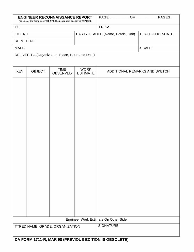
ENGINEER RECONNAISSANCE REPORTFor use of the form, see FM 5-170; the proponent agency is TRADOC.
PAGE __________ OF ___________ PAGES
TO FROM
FILE NO PARTY LEADER (Name, Grade, Unit) PLACE-HOUR-DATE
REPORT NO
MAPS SCALE
DELIVER TO (Organization, Place, Hour, and Date)
KEY OBJECT TIMEOBSERVED
WORKESTIMATE ADDITIONAL REMARKS AND SKETCH
Engineer Work Estimate On Other Side
TYPED NAME, GRADE, ORGANIZATION SIGNATURE
DA FORM 1711-R, MAR 98 (PREVIOUS EDITION IS OBSOLETE)
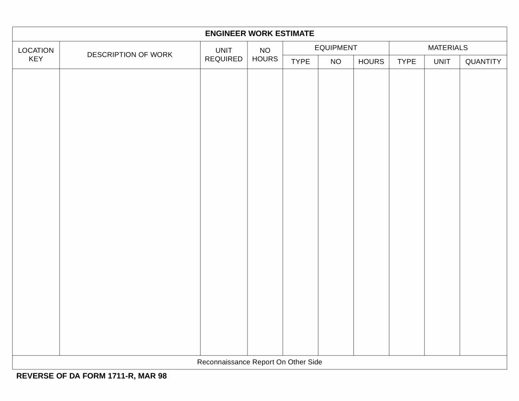
ENGINEER WORK ESTIMATE
LOCATION KEY
DESCRIPTION OF WORKUNIT
REQUIREDNO
HOURS
EQUIPMENT MATERIALS
TYPE NO HOURS TYPE UNIT QUANTITY
Reconnaissance Report On Other Side
REVERSE OF DA FORM 1711-R, MAR 98
FM 5-170
By Order of the Secretary of the Army:
DENNIS J. REIMERGeneral, United States Army
Chief of Staff
Official:
JOEL B. HUDSONAdministrative Assistant to the
Secretary of the Army
DISTRIBUTION:
Active Army, Army National Guard, and US Army Reserve: To be distributed in accordance with the initial distribution number 115747, requirements for FM 5-170.
5 May 1998
04699

PIN: 076496-000