QHY-8 6 Mega Pixel Cooled astronomical CCD Camera User… Users manual.pdf · 6 Mega Pixel Cooled...
24
Distributed by Gama Electronics Pty. Ltd Australia QHY-8 6 Mega Pixel Cooled astronomical CCD Camera User’s guide Ver. 1.0 Gama Electronics Pty. Ltd ©
-
Upload
truongtuyen -
Category
Documents
-
view
253 -
download
0
Transcript of QHY-8 6 Mega Pixel Cooled astronomical CCD Camera User… Users manual.pdf · 6 Mega Pixel Cooled...

Distributed by Gama Electronics Pty. Ltd Australia
QHY-8
6 Mega Pixel
Cooled astronomical CCD Camera
User’s guide
Ver. 1.0 Gama Electronics Pty. Ltd ©

Thank you for purchasing a QHY
Camera. I’m sure that it will give you
hours of pleasure doing what its
supposed to do, and that’s image.
Please take the time to read this
manual so you can familiarise yourself
with some basic understanding of how
the CCD camera works, and how to
get the most from your camera.
1) How to connect your camera
When you first open your package, please check to make sure everything you ordered is there.
Basic Package
1 x QHY-8
1 x Filter/Nose piece
1 x DC101 Supply Regulator
1 x 1 Meter Svideo cable
1 x 1 Meter DC supply cable
1 x CD Drivers and software
If you find your package is damaged please contact your dealer immediately.

Parts description.
1 – QHY-8
2 – Filter/nose piece
3 – Regulator
4 – Air sealed carry case
5 – Silicone Gel heater
6 – Svideo cable
7 – DC Power cable
8 – *Plug pack supply
* Model and power rating may vary.
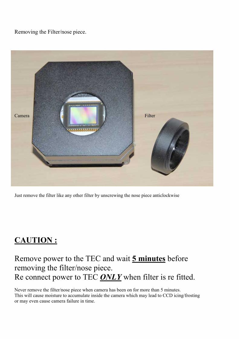
Removing the Filter/nose piece.
Camera Filter
Just remove the filter like any other filter by unscrewing the nose piece anticlockwise
CAUTIO% :
Remove power to the TEC and wait 5 minutes before
removing the filter/nose piece.
Re connect power to TEC O�LY when filter is re fitted.
Never remove the filter/nose piece when camera has been on for more than 5 minutes.
This will cause moisture to accumulate inside the camera which may lead to CCD icing/frosting
or may even cause camera failure in time.

2) The connections :
Connect Svideo leads from the
Camera to the Regulator. The
Sockets are both 4 pin.
Next connect the DC cable from
the TEC cooler socket of the
camera to the Regulator. The
sockets are both 1 pin.
You should now have a similar
image as this one on the right.
The USB socket accepts only USB2.0 interface and cables, as the camera operates at very high
speeds and requires the right type of interface and cables
Lastly, connect the power supply
to the “Input” of the Regulator..
The camera is ready for imaging

3) How does a CCD camera work :
Before we look at how to operate
the camera, lets look at some
basic theory of the CCD camera.
What is a CCD camera ?, well,
its similar to your DSLR or
pocket digital camera, except
that its been designed
specifically to do only one
function.
The astronomical camera is a
specialized instrument that is
specifically made to collect as
much photons as possible while
at the same time maintain the
lowest temperature it can for the
CCD sensor to obtain the lowest
noise possible.
The CCD image sensors can be implemented in several
different architectures. The most common are full-frame,
frame-transfer and interline. The distinguishing characteristic
of each of these architectures is their approach to the problem
of shuttering.
In a full-frame device, all of the image area is active and there
is no electronic shutter. A mechanical shutter must be added to
this type of sensor or the image will smear as the device is
clocked or read out.
With a frame transfer CCD, half of the silicon area is covered
by an opaque mask (typically aluminium). The image can be
quickly transferred from the image area to the opaque area or
storage region with acceptable smear of a few percent. That
image can then be read out slowly from the storage region
while a new image is integrating or exposing in the active area.
Frame-transfer devices typically do not require a mechanical
shutter and were a common architecture for early solid-state
broadcast cameras. The downside to the frame-transfer
architecture is that it requires twice the silicon real estate of an
equivalent full-frame device; hence, it costs roughly twice as
much.
The interline architecture extends this concept one step further
and masks every other column of the image sensor for storage.
In this device, only one pixel shift has to occur to transfer from
image area to storage area; thus, shutter times can be less than a
microsecond and smear is essentially eliminated. The
advantage is not free, however, as the imaging area is now
covered by opaque strips dropping the fill factor to
approximately 50% and the effective quantum efficiency by an
equivalent amount. Modern designs have addressed this
deleterious characteristic by adding microlenses on the surface
of the device to direct light away from the opaque regions and
on the active area. Microlenses can bring the fill factor back up
to 90% or more depending on pixel size and the overall
system's optical design.
The choice of architecture comes down to one of utility. If the
application cannot tolerate an expensive, failure prone, power
hungry mechanical shutter, then an interline device is the right
choice. Consumer snap-shot cameras have used interline
devices. On the other hand, for those applications that require
the best possible light collection and issues of money, power
and time are less important, the full-frame device will be the
right choice. Astronomers tend to prefer full-frame devices.
The frame-transfer falls in between and was a common choice
before the fill-factor issue of interline devices was addressed.
Today, the choice of frame-transfer is usually made when an
interline architecture is not available, such as in a back-
illuminated device.
CCD’s containing grids of pixels are used in digital cameras,
optical scanners and video cameras as light-sensing devices.
They commonly respond to 70% of the incident light (meaning
a quantum efficiency of about 70%) making them far more
efficient than photographic film, which captures only about 2%
of the incident light.
Most common types of CCD’s are sensitive to infrared light,
which allows infrared photography, night-vision devices, and
zero lux (or near zero lux) video-recording/photography.
Because of their sensitivity to infrared, CCD’s used in
astronomy are usually cooled to liquid nitrogen temperatures,
because infrared black body radiation is emitted from room-
temperature sources. One other consequence of their sensitivity

to infrared is that infrared from remote controls will often
appear on CCD-based digital cameras or camcorders if they
don't have infrared blockers. Cooling also reduces the array's
dark current, improving the sensitivity of the CCD to low light
intensities, even for ultraviolet and visible wavelengths.
Due to the high quantum efficiencies of CCD’s, linearity of
their outputs (one count for one photon of light), ease of use
compared to photographic plates, and a variety of other
reasons, CCD’s were very rapidly adopted by astronomers for
nearly all UV-to-infrared applications.
Thermal noise, dark current, and cosmic rays may alter the
pixels in the CCD array. To counter such effects, astronomers
take an average of several exposures with the CCD shutter
closed and opened. The average of images taken with the
shutter closed is necessary to lower the random noise. Once
developed, the “dark frame” average image is then subtracted
from the open-shutter image to remove the dark current and
other systematic defects in the CCD (dead pixels, hot pixels,
etc.). The Hubble Space Telescope, in particular, has a highly
developed series of steps (“data reduction pipeline”) used to
convert the raw CCD data to useful images.
CCD cameras used in astrophotography often require sturdy
mounts to cope with vibrations and breezes, along with the
tremendous weight of most imaging platforms. To take long
exposures of galaxies and nebulae, many astronomers use a
technique known as auto-guiding. Most autoguiders use a
second CCD chip to monitor deviations during imaging. This
chip can rapidly detect errors in tracking and command the
mount's motors to correct for them.
An interesting and unusual astronomical application for CCD’s,
is called "drift-scanning", where you use a CCD to make a
fixed telescope behave like a tracking telescope and follow the
motion of the sky. The charges in the CCD are transferred and
read in a direction parallel to the motion of the sky, and at the
same speed. In this way, the telescope can image a larger
region of the sky than its normal field of view. The Sloan
Digital Sky Survey is the most famous example of this, using
the technique to produce the largest uniform survey of the sky
yet.

Colour Sensors
Digital colour cameras generally use a Bayer mask over the
CCD. Each square of four pixels has one filtered red, one blue,
and two green (the human eye is more sensitive to green than
either red or blue). The result of this is that luminance
information is collected at every pixel, but the colour resolution
is lower than the luminance resolution.
A Bayer filter mosaic is a colour filter array (CFA) for
arranging RGB colour filters on a square grid of photo sensors.
Its particular arrangement of colour filters is used in most
single-chip digital image sensors used in digital cameras,
camcorders, and scanners to create a colour image. The filter
pattern is 50% green, 25% red and 25% blue, hence is also
called GRGB or other permutation such as RGGB.
It is named after its inventor, Dr. Bryce E. Bayer of Eastman
Kodak. Bayer is also known for his recursively defined matrix
used in ordered dithering.
A Bayer filter on a CCD
An RGBE filter on a CCD

Bayer pattern on CCD sensor showing only the constituant colors passing thru.
An Basic CCD Color sensor.

CCD Sensor sizes
Sensors (CCD / CMOS) are often referred to with an imperial
fraction designation such as 1/1.8" or 2/3", this measurement
actually originates back in the 1950's and the time of Vidicon
tubes. Compact digital cameras and Digicams typically have
much smaller sensors than a Digital SLR and are thus less
sensitive to light and inherently more prone to noise.
Type Aspect Ratio Width
mm
Height
mm
Diagonal
mm
Area
mm2
Relative
Area
1/6" 4:3 2.300 1.730 2.878 3.979 1.000
1/4" 4:3 3.200 2.400 4.000 7.680 1.930
1/3.6" 4:3 4.000 3.000 5.000 12.000 3.016
1/3.2" 4:3 4.536 3.416 5.678 15.495 3.894
1/3" 4:3 4.800 3.600 6.000 17.280 4.343
1/2.7" 4:3 5.270 3.960 6.592 20.869 5.245
1/2" 4:3 6.400 4.800 8.000 30.720 7.721
1/1.8" 4:3 7.176 5.319 8.932 38.169 9.593
2/3" 4:3 8.800 6.600 11.000 58.080 14.597
1" 4:3 12.800 9.600 16.000 122.880 30.882
4/3" 4:3 22.500 18.000 28.814 405.000 101.784
Other image sizes as a comparison
APS-C 3:2 25.100 16.700 30.148 419.170 105.346
35mm 3:2 36.000 24.000 43.267 864.000 217.140
645 4:3 56.000 41.500 69.701 2324.000 584.066
4) Taking your first image.
First you need to connect the camera to the telescope by either sliding
the nose/filter of the camera into the focuser and tightning the focuser
locking screw(s), or by attaching it directly to a T thread adapter to
your telescope.
Next point the telescope to a bright star or object and take a short
exposure, say 2 seconds using your softwares focus function. You
should see some sort of image appear, and you will now need to make
adjustments in focus to get a sharp image. Once you have a semi good
focus, you will need to decrease the exposure time in order to create a
smaller star image, so that its easier to see if fine focusing is required.
The addition of a Hartman Mask is a great tool to have when focusing,
or any other focusing tools that may be available, like using FWHM
for focusing. It is a good idea to zoom in on your star image, as you
will see finer detail which will allow you to in turn, produce a better
focus.
Once focus is obtained, move the telescope to the object you wish to
image. Take an initial image so you can place the object in the centre
of the CCD frame by moving the telescope in the direction required.
Once you have focus, and alignment, we are ready to take an image.
Setup your exposure times, Gain and Offsett and start your session.
What is Offset and Gain that is used to setup the camera ?.
Gain is used to increase the levels sent from the CCD before its read
be the A/D converter to preserve very small and minute levels. For
example, lets say the data 0.1, 0.3, 1 and 1.2 is being sent. Well, if no
gain was used, the A/D converter will only see 0, 0, 1, 1 because it
cannot do fractions. So the end result is the same intensity being
displayed, and you loose the subtle changes. But by using gain, we
increase the values to a point where the A/D converter does recognise
them, e.g. from 0.1, 0.3, 1 to 1, 3, 10, 12 etc.
Offsett is used to help and setup the right point so the A/D converter
is able to convert the data so as to avoid any values lower than 1. It
does this by providing a DC voltage in the data path.
But be aware, an increase of gain has an effect on Dynamic range and
the steps between subtle changes is decreased.

Finding your Offset/Gain
Connect your camera to your PC and allow the camera to cool
down for 10 minutes. Make sure you have the lens cap on the
front of the camera.
A setting of, Gain 50 and Offset to 125 is a good default to start
with. Also make sure to use “Low” download speed for
downloading to your PC.
Take a Bias Frame (With the shortest possible time in your
exposure settings) by selecting “Bias frame” from your camera
control software menu.
You should have an image as shown below when finished.
Thanks to CS Christoph for this image

If your image appears black, you will need to change your
Offset by adding a small number. Say, from 125 to 130
Redo another Bias frame and re check the image again. If its
still black, add a further value and re test again, etc.
You will want a value between 400 to 1000 as a Maximum
Pixel Value, before your good to go.
In time you will be able estimate your values and just enter an
offsett and gain with experience.
Now with the Gain and Offsett taken care of, you can proceed
to take your image.
Please refer to your Processing software to process your
images.
5) How to use the Silicone Gel heater for removing moisture from the camera.
After using your QHY-8, you may either, leave the filter on and just pack the camera away
or if you used various filters during your imaging session, and you have opened the camera
seal by removing the filter/nose piece, then you may use the Silicone Gel heater because
you may have some moisture within the camera cavity that must be removed before the
next imaging session.
This can be easily be done by first releasing the AC socket prongs by sliding the button on
the side of the Gel heater.
Depending on your country, you may need a socket changer to fit your power point socket.
Optional Socket converter
Next, just plug in the heater and allow to heat at least
one hour.
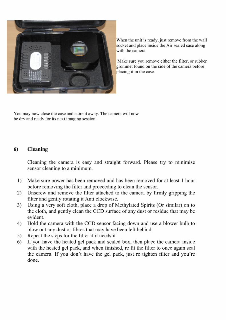
When the unit is ready, just remove from the wall
socket and place inside the Air sealed case along
with the camera.
Make sure you remove either the filter, or rubber
grommet found on the side of the camera before
placing it in the case.
You may now close the case and store it away. The camera will now
be dry and ready for its next imaging session.
6) Cleaning
Cleaning the camera is easy and straight forward. Please try to minimise
sensor cleaning to a minimum.
1) Make sure power has been removed and has been removed for at least 1 hour
before removing the filter and proceeding to clean the sensor.
2) Unscrew and remove the filter attached to the camera by firmly gripping the
filter and gently rotating it Anti clockwise.
3) Using a very soft cloth, place a drop of Methylated Spirits (Or similar) on to
the cloth, and gently clean the CCD surface of any dust or residue that may be
evident.
4) Hold the camera with the CCD sensor facing down and use a blower bulb to
blow out any dust or fibres that may have been left behind.
5) Repeat the steps for the filter if it needs it.
6) If you have the heated gel pack and sealed box, then place the camera inside
with the heated gel pack, and when finished, re fit the filter to once again seal
the camera. If you don’t have the gel pack, just re tighten filter and you’re
done.

7) Camera Features
A Proven and documented High performance multi-function
electronic design, and a built in USB2.0, assures high speed
data transfer rates yet provides a very small footprint that
produces very little noise, this is due to component count being
kept to a bare necessity, and in turn reducing heat and noise.
Many tests have been conducted by many amateurs, with great
rock solid results
Double Correlated Sampling along with the ultra low kTC
noise gives the product a very smooth image output.
The TEC used in the QHY-8 is a large 40mm x 40mm 2 stage
Peltier (2 Peltier’s sand witched together), unlike other cameras
that use the smaller 20mm x 20mm or 10mm x 10mm single or
dual stage TEC's.
This allows the sensor to cool faster and maintain a better
stability due to changes in component temperatures inside the
camera.
Those cameras struggle to cool the sensor due to the
current/power rating of the TEC, there is no problem with the
QHY-8 cooling down in this area.
The fan mounted on the back is a low vibration and low noise
80mm unit. It provides plenty of cooling to the heatsink and
produces no vibration to your system. Compare this with many
cameras using the smaller 20mm and 40mm fans. Without
proper cooling it will lead to excess heat within the camera,
which in turn affects noise levels to the CCD sensor. The QHY
series do not suffer from excess heat within the camera.
Other cameras try to lower heat by reducing the power to the
TEC so the cooling fan/heatsinks can cope, which in turn drops
the efficiency of the cooling system during warm or hot nights.
Ultra low noise Preamp Readout, noise is 8 -12e
Programmable Gain Amplifier with analog and digital stages
allows gain to be controlled by the user.
16 bit AD converter allowing 65535 contrast levels.

By having the power supply and regulation (DC-101) externally
and away from the camera electronics, we remove all unwanted
noise and heat away from the heat sensitive components inside.
This effectively lowers the thermal and electrical noise further
within the camera and allows for higher sensitivity overall.
Exposure steps are adjustable down to as low as 1ms
increments.
High speed transfer data rate by using the USB2.0 interface.
Normal download is at 600 KPixels/s. Fast preview mode is 6
Mpixels/s (Allowing fast focus, or object alignment).
This speed allows you to download the whole 6 Mpixel image
within 2 seconds.
The Progressive CCD is the preferred choice for the CCD
sensor. Progressive CCD scan design produces less noise and
temperature within the camera, plus the exposures are evenly
illuminated, even for short exposures.
Interlaced sensors distort the exposure by unevenly exposing
the odd and even fields of the CCD sensor during short
exposures.
This may directly affect your Flat frames and Bias frames,
because while the data is read from the odd field, the even field
is STILL being exposed, with up to 30 seconds with some
slower PC's, resulting in an uneven exposure.
This is why mechanical shutters are required by manufacturers.

8) Specifications: QHY-8
CCD Sensor: Sony ICX-453
Total pixel: 3110 x 2030
Active pixels: 3032 x 2016
Pixel Size: 7.8um x 7.8um square
Colour method: RGB BAYER film on CCD
Effective sensor area: 28.4 mm diagonal
Readout noise: 8 -12 e @600Kpixel/s
QE: 60% at Green (Peak) , 50% at Blue and H.a
QE Boost: Microlensing on chip
Scanning method: Progressive Scan
NABG: -110dB
Cooling System: 2-Stage TEC (Up to -45C below ambient)
Power consumption: 12V 3.3A
Additional Cooling: Built in 12V low noise FAN
Mounting Threads: M42, 0.75 pitch
Quantum Efficiency ICX-453 Sony Sensor

Spectrum response curve for UVIR Filter:
Wavelength in [nm]
9) Camera measurements :
CCD Offset Dimensions:
Dimensions 90 x 90 x 55 mm

10) Problems and fixes
Q: Why does my sensor fog up?
A: This will NOT occur if the filter is firmly attached to the camera, but when the
sealed chamber has been opened by removing the Filter, you allow the local air
around you that contains a higher % of humidity inside the chamber then what was
originally sealed.
But it is easily rectified by simply re sealing the camera by re fitting the filter back
on firmly in a dry environment, like near a heater, or other dry hot air.
Q: My sensor forms Ice crystals on it why ?.
A: This is caused by residue left on the sensor either after a poor Sensor clean, or by
some other residue that may have formed after many hours of use during high
humidity.
To rectify, open the CCD chamber by removing the filter/nose piece, then apply a
small drop of alcohol or similar cleaning fluid to the CCD glass surface, and gently
wipe the whole sensor, even the corners. If you leave anything behind, then this will
freeze and create the ice pattern on your sensor.
Once you have cleaned and re fitted the filter back on (Using the dry hot air
method), the camera is again ready for action. Just a note, it is important to
understand if the sensor is clean and the chamber is sealed correctly, the CCD will
never fog or ice up.
Q: The back of the camera is very hot, yet the front is cold, why?
A: The QHY-8 is fitted with a dual stage Peltier device. This device is able to change
temperature of anything it is attached too, a further -40 degrees C from ambient
temperature. So by placing directly behind the CCD, we cool it down a further 40
degrees
and enjoy the benefits of low noise as a consequence. But, what it cools on one side,
the Peltier heats +40 deg C on the other side of itself. Here is where we place the
heat sink and fan, and this is where all the heat is dissipated and released to
atmosphere.
Q: I use my camera remotely, can I conserve battery power and still run my QHY-8 for
hours?
A: Yes, by reducing the amount of voltage/current to the TEC (Peltier), you increase
your operating time. The only difference you will notice is that it will take a little
longer to reach its operating temperature of around -40 Deg C Delta.
Q: Is the cable that supplies power to the camera a Svideo cable as used in TV’s?.
A: Yes, so if you ever lose, break, or just want to extend the length, you can use a
standard Svideo lead.
11) Glossary:
Charge Amplifier:
Charge amplifier is a circuit whose equivalent input
impedance is capacitance so that it provides a very high value
of impedance at low frequencies. Thus contrary to what its
name may suggest, a charge amplifier does not amplify the
electric charge present at its input. Its function is actually to
obtain a voltage, proportional to that charge and yield a low
output impedance. Thus, it is a charge-to-voltage converter.
Charge amplifiers are often found in the readout circuitry of
CCD imagers. In read-out circuits the objective is usually to
measure the very small charge stored within an in-pixel
capacitor, despite the capacitance of the circuit-track to the
readout circuit being a couple of orders of magnitude greater
than the in-pixel capacitor.
Frame transfer CCD is a specialized CCD, often used in
astronomy, designed for high exposure efficiency and
correctness.
The normal functioning of a CCD, astronomical or otherwise,
can be divided into two phases: exposure and readout. During
the first phase, the CCD passively collects incoming photons,
storing electrons in its cells. After the exposure time is passed,
the cells are read out one line at a time.
During the readout phase, cells are shifted down the entire area
of the CCD. While they are shifted, they continue to collect
light. Thus, if the shifting is not fast enough, errors can result
from light that falls on a cell holding charge during the transfer.
These errors are referred to as "vertical smear" and cause a
strong light source to create a vertical line above and below its
exact location. In addition, the CCD cannot be used to collect
light while it is being read out. Unfortunately, a faster shifting
requires a faster readout, and a faster readout can introduce
errors in the cell charge measurement, leading to a higher noise
level.
A frame transfer CCD solves both problems: it has a hidden,
not normally used, area containing as many cells as the area
exposed to light. Typically, this area is covered by a reflective
material such as aluminium. When the exposure time is up, the
cells are transferred very rapidly to the hidden area.

Here, safe from any incoming light, cells can be read out at any
speed one deems necessary to correctly measure the cells'
charge. At the same time, the exposed part of the CCD is
collecting light again, so no delay occurs between successive
exposures.
The downside of such a CCD is the higher cost: the cell area is basically doubled, and more
complex control electronics are needed.
Quantum Efficiency (QE) is a quantity defined for a
photosensitive device such as photographic film or a charge-
coupled device (CCD) as the percentage of photons hitting the
photo reactive surface that will produce an electron–hole pair. It
is an accurate measurement of the device's electrical sensitivity
to light. Since the energy of a photon depends on (more
precisely, is inversely proportional to) its wavelength, QE is
often measured over a range of different wavelengths to
characterize a device's efficiency at each photon energy.
Photographic film typically has a QE of much less than 10%,
while CCD’s can have a QE of well over 90% at some
wavelengths.
Dark current is the relatively small electric current that flows
through a photosensitive device such as a photomultiplier tube,
photodiode, or charge-coupled device even when no photons
are entering the device. It is referred to as reverse bias leakage
current in non optical devices and is present in all diodes.
Physically, dark current is due to the random generation of
electrons and holes within the depletion region of the device
that are then swept by the high electric field.
Dynamic Range of a CCD is its ability to measure and
differintiate between light and dark (Contrast range).
Full Well Capacity is the largest charge a pixel can hold before
saturation, which results in degradation of the signal. When the charge in a
pixel exceeds the saturation level, the charge starts to fill adjacent pixels
(Over flows), a process known as Blooming. The camera also starts to
deviate from a linear response and hence compromises the quantitative
performance of the camera. Larger pixels have lower spatial resolution
(Blocky image) but their greater well capacity offers higher dynamic
range which can be important for some applications.
Bias Frame is an image made with an integration of zero seconds and
shutter closed. It contains the amplifier zero-point offset, the random
readout noise from the amplifier and the noise from camera electronics
Dark Frame is a technique used to identify and remove noise in a CCD
imaging device. This is done by recording without exposing the CCD,
usually by leaving the shutter closed and putting the CCD in a dark room.
These "dark frames" are then subtracted from subsequent images to
correct for extraneous noise in the CCD. The noise is often caused by hot
pixels. Hot pixels are sensors on the CCD with higher than normal charge
leakage. On long exposure, they can appear as bright pixels.
Sensors on the CCD that always appears as brighter pixels are called stuck
pixels while sensors that only brighten up after long exposure are called
hot pixels.
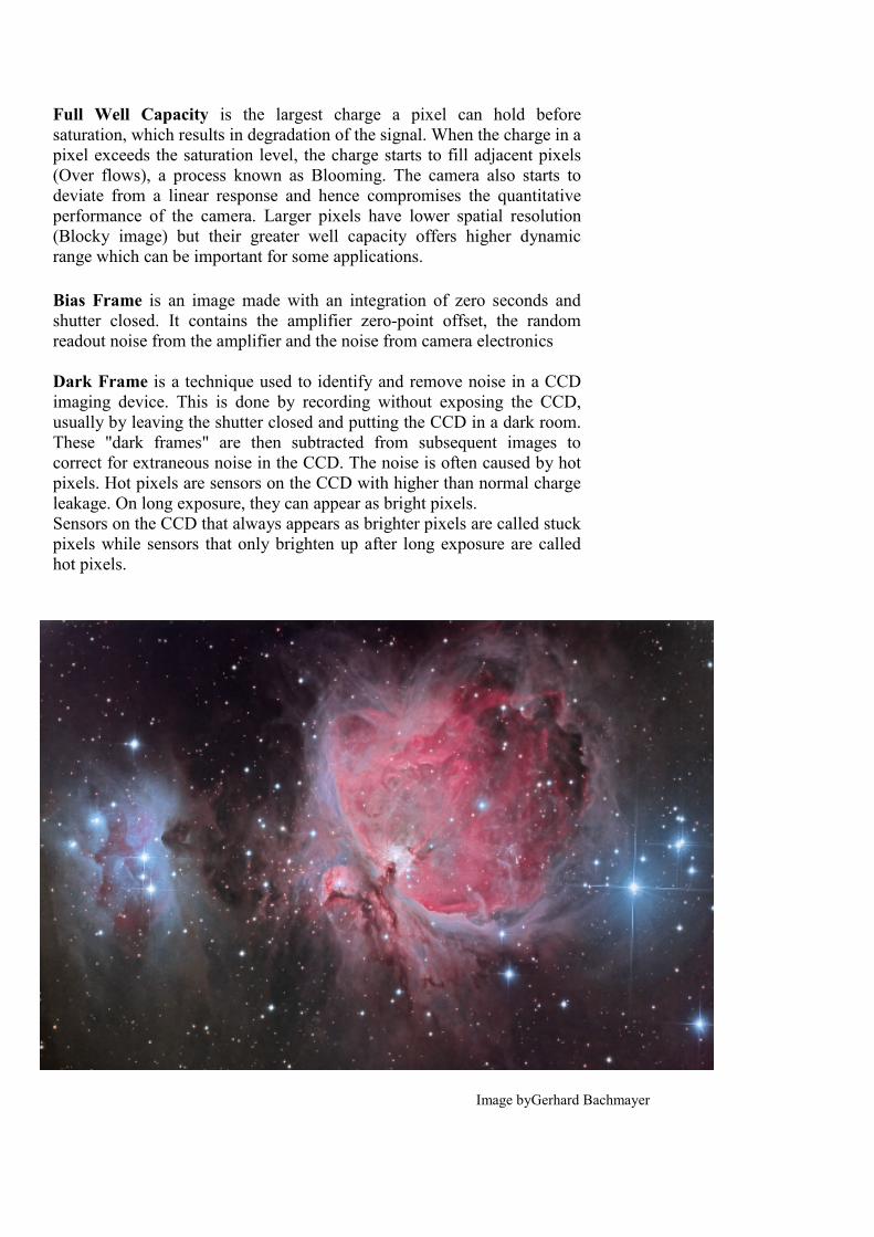
Image byGerhard Bachmayer

Produced edited by Gama Electronics Pty. Ltd
No part of this document may be copied or printed without the prior permission of Gama Electronics ©