Qhd 1 Brakes
5
QHD-1 “STING” / QHD-1 PRO “STING PRO” HYDRAULIC DISC BRAKE SYSTEM rear hub front hub H U B (15.3min) 15.25 B (15.3min) A 10.5 A B 1. QHD-1 MC assembly 1 2. Grub screw 1 3. Reservoir cap 1 4. Clamp 1 5. Clamp bolt 2 6. Push rod 1 7. Pin for pads 1 8.QHD-1 caliper assembly 1 9. Disc pads 1 10. Bleed nipple 2 11. Bleede cap 1 NO. Des. Qty. NO. Des. Qty. □ STANDARD FITTINGS 1. QHD-1 (PRO) caliper is compatible with MANITOU forks with a distance between mounting of 74.2mm. It can be converted to International Standard when using our front and/or rear adaptor brackets. 2. Mounting bolts: M6 x 18mm (incl. Washer) x 4pcs. 3. Disc rotor:φ160 for the front and φ140 for the rear; using adaptor brackets, it can be φ180 for the front and φ160 for the rear or φ203 for the front and φ180 for the rear. 4. Rotor screws: 6 pcs. □ RELATED MOUNTING SPECIFICATIONS 1. Specifications of front fork and rear dropout QHD-1 (PRO) is compatible to International Standard and Manitou fork, see drawings below: 2. Hub The offset of hubs for QHD-1 (PRO) disc brake system is the same as Hayes (SHIMANO) specifications, see drawings below:
-
Upload
joesantane -
Category
Documents
-
view
274 -
download
17
Transcript of Qhd 1 Brakes

8/6/2019 Qhd 1 Brakes
http://slidepdf.com/reader/full/qhd-1-brakes 1/5
QHD-1 “STING” / QHD-1 PRO “STING PRO” HYDRAULIC DISC BRAKE SYSTEM
rear hub
front hub
HUB
(15.3min)15.25
B(15.3min)
A10.5
A
B
1. QHD-1 MC assembly 1
2. Grub screw 1
3. Reservoir cap 1
4. Clamp 1
5. Clamp bolt 2
6. Push rod 1
7. Pin for pads 1
8.QHD-1 caliper
assembly
1
9. Disc pads 1
10. Bleed nipple 2
11. Bleede cap 1
NO. Des. Qty. NO. Des. Qty.
□ STANDARD FITTINGS
1. QHD-1 (PRO) caliper is compatible with MANITOU forks with a distance between mounting of 74.2mm. It canbe converted to International Standard when using our front and/or rear adaptor brackets.
2. Mounting bolts: M6 x 18mm (incl. Washer) x 4pcs.
3. Disc rotor:φ160 for the front and φ140 for the rear; using adaptor brackets, it can be φ180 for the front
and φ160 for the rear or φ203 for the front and φ180 for the rear.
4. Rotor screws: 6 pcs.
□ RELATED MOUNTING SPECIFICATIONS
1. Specifications of front fork and rear dropout
QHD-1 (PRO) is compatible to International Standard and Manitou fork, see drawings below:
2. Hub
The offset of hubs for QHD-1 (PRO) disc brake system is the same as Hayes (SHIMANO) specifications, see
drawings below:

8/6/2019 Qhd 1 Brakes
http://slidepdf.com/reader/full/qhd-1-brakes 2/5
3. Caliper
QHD-1 (PRO) caliper is completely sealed, and has been tested to take high pressure. It is prohibited toloosen any screw/bolt on the caliper (the bleed nipple can be loosened only when changing brake fluid);
otherwise it could cause leaking and consequently no braking.
*Warning:No brake fluid leaking is allowed. Riding should be stopped at once when there is leaking.
Repairing should be performed by qualified dealers!
4. Rotor
QHD-1 (PRO) rotor specifications are φ160×2mm( thickness) for front,φ140×2mm for rear.They can beφ180×2mm for front,φ160×2mm for rear or φ203×2mm for front,φ180×2mm for rear when using
adaptor brackets.
*Warning:1. Under normal riding condition, there will be slight wear on rotor, the wear will be more aftermore braking. Therefore it is required to check the wear on rotor regularly. Disc rotor shouldbe changed when it has been deformed or worn excessively.
2. After use and or intensive braking, the temperature of the rotor becomes high. Do not touch
the rotor.
□ ASSEMBLY
*Warning:As the disc pads are self adjusting, DO NOT pull brake lever before it is fully assembled with
rotor. The more pulls on brake lever without rotor in makes the gap between disc pads smaller
and will not allow disc rotor in. Use spacer to insert in between the pads and push
them back to original positions.
I、Assemble BMC bracket onto handle bar.
II、Use the 6 rotor screws( 3mm Allen key, torque40∼50 kg-cm ) to tighten disc rotor onto the disc hub.
※Caution:
1. Follow the arrow mark for rotor direction.
2. The 6 rotor screws must be tightened before riding.
3. The 6 rotor screws should be tightened in diagonal sequence.
4. The 6 rotor screws should be replaced after disassembly for 3-4 times as the Nylok will not function
as well as it should be then.
III、Assemble the wheel fixed with rotor onto the front fork or rear dropout and tighten the wheel.
IV、Assemble the caliper onto the front fork or rear dropout.:
1. International standard fork:
Tighten the front or rear adaptor bracket onto the front fork or dropout.( Use 2pcs M6×18mm bolts,
torque 60±5kg-cm ).
Mount the caliper to the adaptor bracket with 2pcs M6×18 bolts.( DO NOT TIGHTEN THE BOLTS, so
that the caliper can move on bracket )
2. MANITOU fork:
Mount the caliper to the MANITOU fork with 2pcs M6 x 18 bolts. ( DO NOT TIGHTEN THE BOLTS, so
that the caliper can move on bracket )
V、 Pull the brake lever to make disc pads clamp to disc rotor ( caliper will self adjust alignment ),then tighten
the 2pcs M6 bolts.
VI、Spin the wheel to make sure the disc rotor is clear to disc pads. If it is clear, then it is OK; if not, then slack
the bolts and redo step V above.
VII、Adjust the angle of brake lever on the push rod with 2mm Allen key. ( Clockwise, for larger angle; Counter
clockwise, for smaller angle ).
VIII、Test riding:
Braking force on the first 10∼30 pulls is not as powerful.( New disc pads need to be bedded in )
〔*Warning:Do not ride at high speed when doing test riding, keep safe distance.〕
□ MAINTENANCE
I. Changing disc pads:
QHD-1 (PRO) hydraulic caliper is designed with self-adjustment disc pad function, No pad adjustment isrequired before the disc pads are worn out. It is required to stop riding and change new disc pads when the

8/6/2019 Qhd 1 Brakes
http://slidepdf.com/reader/full/qhd-1-brakes 3/5
brake lever needs to be pulled with a large travel to stop the bike or there is noise between disc pads androtor.
*Warning:Keep disc pads free from oil or grease; otherwise it will cause no braking.
1. Remove the wheel.
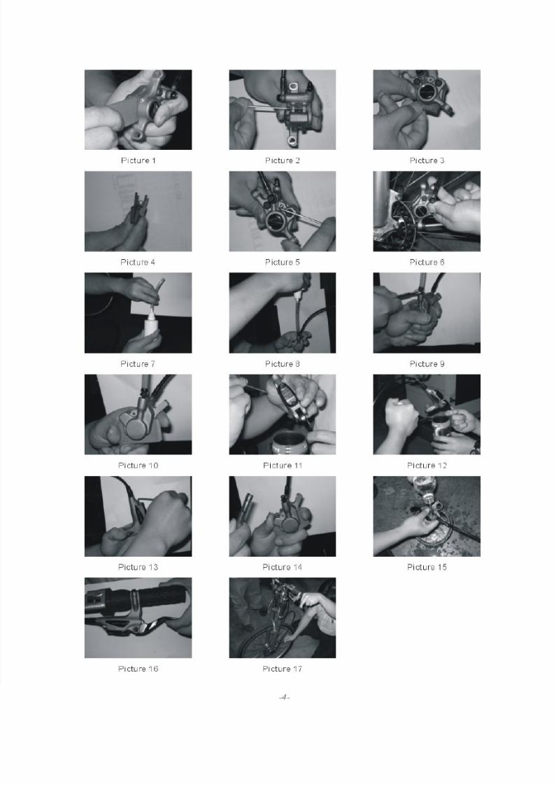
2. Insert the spacer into the gap between the disc pads and push the disc pads back to original positions.
See picture ……1.
3. Use 2mm Allen key to remove the pin holding the disc pads and pull out the disc pads. See picture ….2
and 3.4. Place new disc pads and spring in the disc pad housing, then place the locating pin through the holes on
backing plate of disc pads and tighten the pin ( 25 kgf.cm ). See picture ……4 and 5.
5. Put the wheel back on the fork or dropout and tighten.
6. Spin the wheel and make sure it is clear between the rotor and disc pads. If it doesn’t clear, redo the
step VI in Assembly above.
※Caution :
1. Braking force on the first 10∼30 pulls is not as powerful.( New disc pads need to be bedded in )
Do not ride at high speed when doing test riding, keep a safe distance.
2. It is normal that there might be braking noise in the wet. The noise will disappear after the disc padsbecome dry.
II、Changing brake fluid:
QHD-1 (PRO) hydraulic disc brake uses Fuchs DOT#4 brake fluid. Other branded DOT#4 brake fluid is
compatible.
*Warning:1. Never add or mix with other mineral oil or other than DOT#4 fluid as it will cause damage to
the oil seals in the system and cause failure of braking.
2. Brake fluid absorbs moisture after a period of time, which will reduce its boiling
temperature. Brake fluid should be changed in 2 years to avoid poor braking.
3. Brake fluid causes irritation to the skin, avoid direct contact the brake fluid.
Water skin once contact to brake fluid.
1. Tools:
‧Empty container( for used fluid) ‧DOT#4 Oil Bleed kit (includes: DOT#4 fluid, 6mm I/D tubing)
‧8mm open-end wrench ‧2mm Allen key
‧divider or disc rotor ‧Clean water and a cloth
2. Remove the caliper from front fork or dropout, and keep the grub screw on BMC upright. See picture…6
3. Using the DOT#4 brake fluid bottle, connect the clear soft tube to cone shaped end of the bottle, thenconnect the other end of soft tube to the bleed nipple. Invert the bottle and allow any air bubbles to rise inthe bottle. See picture……7 and 8.
4. Loosen the bleed nipple with an 8mm open-end wrench. See picture … 9.
5. Insert the spacer or disc rotor between the 2 disc pads, and place the empty container below the
reservoir. See picture … 10.6. Remove the grub screw on the BMC. See picture……11
7. Inject brake fluid:
1) Keep the caliper at lower position, inject fluid into caliper slowly by squeezing the bottle and the fluidwill come out from BMC end. Make sure the fluid is injected with no bubbles appearing.
See picture …….12.
2) Then screw in and tighten the grub screw on BMC(10kgf.cm),and tighten the bleed nipple
(torque 50kgf.cm). See picture …..13 and 9.
※Caution:The position of caliper should be higher than BMC when tightening the bleed nipple to
avoid fluid flowing out due to gravity.
8. Remove the hose and clean the excessive fluid. See picture …..14 and 15.9. Primming test: Place disc rotor into the caliper, pull the brake lever several times to check if the
pressure has been built up. While it feels firm , the pressure has been built up. If not, it means that
there is air in the hose, filling should be redone. See picture …..16.

8/6/2019 Qhd 1 Brakes
http://slidepdf.com/reader/full/qhd-1-brakes 4/5
10. Assemble caliper back to fork or dropout, follow steps IV, V, VI in Assembly above for adjustments.
See picture …..17.
III、Changing hose or cutting hose:
1. Tools:
‧Empty container ( for used fluid) ‧DOT#4 bleed kit
‧8mm open-end wrench ‧QUAD QHD-1 maintenance kit
‧spacer or disc rotor ‧O ring × 2 (maintenance kit)
‧2mm Allen key ‧Compression bush ×1 (maintenance kit)
‧Hose cutter
‧Hose connection ×1 (maintenance kit)
※ Hose must be of correct specification.
2. Cutting hose:
1) Loosen compression joint and cut the hose to the required length. Brake hose must be cut square
without fibers coming out.
Standard hose length of QHD-1: for front →1000mm
for rear →1550mm
※Caution:a. Brake fluid must be totally drained before cutting the hose.
chamfered end
Compression bushHose cone
Brake hoseCompression nut
O ring
Hose insert
b. The hose on BMC end should be cut for easier reassembly.
2) Put rubber hose cover through first, then compression nut, then compression bush. Hose should be putthrough the chamfered end of compression bush, and the other end of compression bush flush with theend of hose.
3) Put hose insert on hose then put on an O ring, then screw compression joint into the BMC.
〔※Caution:hose insert must be completely assembled into the hose, otherwise it might cause leakingand no braking〕.
4) Tighten compression nut with 8mm open-end wrench,suggested torque 50∼60kg-cm.
5) Put hose cone in place.
6) Inject fluid according to the steps in section of Changing brake fluid above.(Make sure the air isreleased).
3. Changing hose:
Please contact a qualified dealer for correct replacement accessories.
8/6/2019 Qhd 1 Brakes
http://slidepdf.com/reader/full/qhd-1-brakes 5/5