QD32 Operation man1 - TradeKeyimgusr.tradekey.com/images/uploadedimages/brochures/4/9/5875901... ·...
63
Chaoyang Diesel With High Quality Operation Manual CYQD32 Series Diesel Engine
Transcript of QD32 Operation man1 - TradeKeyimgusr.tradekey.com/images/uploadedimages/brochures/4/9/5875901... ·...

Chaoyang Diesel With
High Quality
Operation Manual
CYQD32 Series Diesel Engine

2
Foreword
CYQD 32 series diesel engine is a new generation diesel engine with high
quality, which is manufactured with international advanced level technology from
Japanese Nissan Diesel. This series includes CYQD32, CYQD32EGR, CYQD32T,
CYQD32Ti four versions. It features with compact in volume, light in weight,
strong in power, capable of climbing, low fuel consumption, easy to start, long life,
low noise, low exhaust pollution and so on. They mainly complete with light-duty
truck, pick-up and light-duty bus, if they are varied, they will apply in other power
mechanicals.
CYQD 32 series diesel engines are advance in performance targets,they have
good structure and all the performance targets have reached the advanced level. In
the meantime, cylinder-block, crankshaft, piston and other key components were
increased strength and toughness, and have had higher service reliability by
adopting new structure, new technology. So if you purchase this kind of engine or
the vehicles with such engine and all kinds of mechanisms will gain better
economic benefit.
The operation manual is comply the purpose of effective operation and
maintenance so as to bring this series diesel engine into full play and keep diesel
engines in constantly well technical condition. The details of diesel engine
operation instruction, maintenance and trouble shooting are given in this manual. If
drivers and service men operate according to the specification, it may surely
benefit.

3
Information and data in this manual are identified with our present products. As
this series diesel engine will be continuously improved as technical development
and requirement by customer, therefore specification listed in this manual are
subjected to chance without notice. Please pay close attention to the differences and
our latest version of operation manual.

4
Cautions
1. Diesel engine VE pump plunger must be in the specific range.
2. After engine starts or before stops, it must idle 3-5 minutes, in order to heat
engine or cool evenly. Generally, you should not change speed and loading, and
idling time can’t excess 10 minutes, no loading and big throttle operation are
strictly prohibited.
3. Before new engine using or change oil, oil filter and stopping for long time
(about one week) to turbocharger and turbocharger inter-cooled diesel, must loose
inlet adapter on super-charge and refill cleaning oil, and make turbo rotor bearing
gain full primary lubrication (when filled oil, pay closed attention to using container,
tool, connection component and surrounding environment must clean).
4. Diesel engine oil must be in accordance with the specifications of the manual and
choose the label and regularly change it in accordance with the specifications of the
manual. It is necessarily deposited and filtered before applying it.
5. Soft water must be used as coolant, or the cooling system circuits may be
blocked.
6. The cleanliness of the air aspirated by diesel engine has important influences to
the life of engine. It is not allowed the engine working without air filler or the air
filler lost efficacy. I t is not allowed the engine running when the intake system
leaking.
7. If the air filter was clogged, it will make the end of compressor of charger leak,
so we must maintenance regularly and change filter.
5
8. When change the primary oil filter after it is full. Apply little oil on the surface of
the seal ring before fix it. Tight the filter by hand until it touched the seal ring, then
tight another 3/4 round.
9. Due to VE pump is lubricated with diesel, in order to ensure the service life of
VE pump, must change the element of the diesel filter and its diesel.
10.You must remember that, according to “The Regulation for New Engine Run-in
Maintenance” for your new engine in the technical service stations of Dongfeng
Chaoyang Diesel Co., Ltd., otherwise you can’t get guarantee. The technical service
centers of Dongfeng Chaoyang Diesel Co., Ltd., to serve you whole-heart in the
nearest station, and perform “run-in maintenance” free of charge.
Please to read Service Manual with engine about detail information

6
Contents
Full load performance curve of Model CYQD32 series diesel engine
Main specifications and technical targets of CYQD32 series diesel engine
Chapter I Technical Performance of Diesel Engine
A. Technical specification of diesel engine
B. Mainly technical data of diesel engine
Chapter II Operation of the Diesel Engine
A. Fuel, lubrication oil and cooling water
B. Preparing before starting
C. Starting of diesel engine
D. Running-in of diesel engine
E. Operation of diesel engine
F. Stop of diesel engine
Chapter III Maintenance of Diesel Engine
A. Routine maintenance
B. Maintenance about ruining 2000km (about 50 hours)
C. Maintenance about ruining 8000km (about 200 hours)
D. Maintenance about ruining 45000km (about 1000 hours)
E. Judgment of main repairing period of diesel engine
7
F. Maintenance in winter operation
Chapter IV Regular Adjustment of Diesel Engine
A. Valve clearance
B. Fan belt
C. Opening pressure and quality of spray about injector
Chapter V Main Parts and System of Diesel Engine
A. Cylinder block
B. Cylinder head
C. Crankshaft and flywheel
D. Piston and connecting rod
E. Transmission system
Chapter Ⅵ Supply System of Diesel Engine
A. Diesel engine combustion and combustion chamber
B. Exhaust gas recirculation system (EGR)
C. Turbo-charge system
D. Turbo-charge Inter-cooling system
E. Fuel supply system

8
Chapter Ⅶ Auxiliary System of Diesel Engine
A. Lubrication system
B. Cooling system
C. Accessory machine
D. Clutch
E. Instruction for preheating device
F. Increasing device for idle
Chapter Ⅷ Trouble & Shooting
A. Difficult in start
B. Unstable speed of idle
C. Insufficient power
D. Big fuel consumption
E. Big oil consumption
F. Water temperature is high in engine outlet
G. Exhaust white smoke
H. Exhaust black smoke
I. Oil pressure is low
J. Trouble caused by turbocharger
Meaning of the Unit Symbol Used
in This Manual and Its Conversion

9
Main specifications and technical targets of CYQD32 series diesel engine CYQD32 CYQD32EGR CYQD32T CYQD32Ti type Vertical, in-line, water cooled, 4 stroke Number of cylinders Bore × Stroke(mm)
4---99.2×102mm
Type of combustion chamber
Swirl chamber
Displacement (L) 3.153 Firing order 1-3-4-2 Aspiration method Natural
aspirated EGR Turbo charge Turbo charge
inter-cooled Max. power kW(Ps)
75.8 (103) 75.8 (103) 80.9 (110) 96 (130) 101.5(138)
Max. power (r/min) 3600 3600 3600 3600 Max. torque N.m (kgf.m)
216 216 221 280 313
Max. torque speed (r/min)
2200 2200 2000 2000
Min specific fuel consumption(g/kW.h)
230 230 230 225
Oil vs fuel (%) < 0.2 < 0.2 < 0.2 < 0.2
Exhaust temperature°C
≤700 ≤700 ≤700 ≤700
Idling speed (r/min) 700±50、850±50 (When the air conditioner is on. ) Max. steady idling speed (r/min)
4700±100
Compression ratio 22:1 Steady governor
rate (%) 17.5
ZEXEL 0.416 0.468 0.527 0.736 Plunger lift of injection pump (mm) DENSO 0.416 0.45 0.594
Emission EUR Ι EUR Ц EUR Ц EUR Ц Noise (dBA)(360r/minfull load)
93.0 93.0 93.0 93.0
Cool start (℃) -35 -35 -35 -35 Overall dimensions (mm) (L×W×H)
72×597×677 721 × 597×677
721 × 701×715
721×701×665
Net mass (kg) 258 260 272 275

10
Chapter I Technical Performance of Diesel Engine
A. Technical specification
1. Engine
Type vertical, in-line, water cooled, 4 stroke
Number of cylinders- Bore ×stroke (mm)
4---99.2×102mm
Cylinder bush no
Type of combustion chamber Swirl chamber
Displacement (L) 3.153
Firing order 1-3-4-2
Direction of rotation
(From the end of flywheel) counter clockwise
Starting method electric starting
Stopping method cut-off fuel supply
Lubrication method compression and splash lubrication
Cooling method forced and closed circuit
2. Accessory parts:
Oil pump gear type
Oil filter spiral
Oil cooler water cooled, built-in type
Water pump centrifugal type

11
Thermostat Opening temperature at 76.5℃
Fan vanes axial flow
Fan clutch silicon oil fan clutch
Fuel injection pump VE distribute pump]
Injector single hole, axial needle, hole diameter is 1mm
Starter electromagnetic control type, 12V, 2.8Kw
Alternator 12V, 70A
B. Main technical data of diesel engine
1. Valve timing (according to crankshaft angle)
CYQD32 CYQD32EGR CYQD32T CYQD32Ti Intake valve opening (B.T.D.C)
16º 16º 19º 19º
Intake valve closing (A.T.D.C)
52º 52º 43º 43º
Exhaust valve opening (B.T.D.C)
66º 66º 60º 60º
Exhaust valve closing (A.T.D.C)
12º 12º 8º 8º
2. Between valve and rocker arm clearance (cool engine)
Intake valve 0.35mm
Exhaust valve 0.35mm
3. Compression clearance (at T.D.C., the clearance between piston top and
cylinder head bottom)
0.8~1.1mm
4. Oil pressure:
Idling oil pressure: 98kPa
Operation oil pressure: 196~490kPa

12
5.Cooling water temperature 80~95℃ (when operation, cooling water
should not boil)
6. Oil capacity in oil sump
7L (Include oil filter)
6.3 L ( No oil filter)
7. Cooling water capacity:
9.5L (only engine)
8. Extension of fan belt
We compress the belt with 39N(4kgf), the single deflection should be between
10~15mm.
9. Main bolt tightening torque:
Cylinder head bolt First tightening torque: 39.3N.m
Second tightening torque: 63.7N.m
Third tightening torque: 900±100
Checking torque 113~132N.m(11.5~13.5kgf.m)
Main bear bolt 167~176N.m(17~18kgf.m)
Connecting rod nut 78~83N.m(8~8.5kgf.m)
Flywheel bolt 167~186N.m(17~19kgf.m)
Camshaft gear compress bolt 57~66N.m(5.8~6.8kgf.m)
Injection pump compress nut 59~69N.m(6~7kgf.m)
Crankshaft front nut 373~402N.m(38~41kgf.m)
Piston cooling nozzle bolt 29~39N.m(3~4kgf.m)

13
Oil drain plug of oil sump 54~59N.m(5.5~6kgf.m)
Injector nut 29~39N.m(3~4kgf.m)
Nut of high pressure oil pipe 20~25N.m(22.5kgf.m)
Notice:
a. To twist the bolt of cylinder head with angle, the other bolts must twist
alternatively them according to specific order with 2-3 times.
b. If non-locking washer were used, pay special attention to tightening
torque.
c. Tightening with lubrication oil when assembly. If the thread of bolt was
damaged, replace it.
10. General bolt tightening torque: (unit: N.m)
M8 16~21
M10 29~39

14
Chapter II Operation of Diesel Engine
To make diesel engine operate properly, not only can keep it in normal operate,
but also can prolong its life.
A. Fuel, lubrication oil and cooling water
1. Fuel:
Fuel: GB252 light diesel fuel can be used. Type of fuel and oil must be
chosen in light of seasons, climate according to the type of national standard. We
suggest that light diesel -35# can be used.
Fuel must be deposited for a 7 days and nights and filtered with silk cloth,
and oil filling tool must be clean.
2. Lubrication oil
Oil is CF-4 grade diesel or special oil for Dongfeng Chaoyang
CYQD32 diesel engine. It can be used as per the following table:
Oil brand Applicable ambient temperature
30# -5℃ ~ 30℃
40# Above 5℃
10W -20℃ ~ -5℃
5W/30 Above -25℃
15W/40 Above -30℃

15
Please remember:
The mechanical load and heat load of this diesel engine both are very high,
every moving parts including turbocharger, they are all belong to high temperature,
high speed and precise moving parts, those have very strict requirement for the oil
quality, so must use specified oil, and select the suitable oil brand according to the
ambient temperature, change the oil in specified interval. Otherwise, it will be very
harmful to the diesel engine and shorten its service life.
Different brand of oil can’t be mixed to avoid bad chemical and physical
reaction to make oil deteriorate.
3. Coolant
Long term of effective coolant must be used, it not only good in cooling, but
also has the function of anti-frozen and anticorrosive. Due to the coolant hole is
very small, if use water as cooling media, it’s very easy to be blocked by scale and
incrustation.
B. Preparing before starting
Before starting diesel engine, normal check-up must be done following:
1. What about the different parts, and what about connections.
2. Whether about engine oil, cooling water and fuel capacity is sufficient,
not sufficient should be filled it.
3. Whether there is any leakage about oil, water and air, if it is leakage, we
should repair it at once.
4. What about electric circuit system is right, and storage battery is

16
sufficient.
5. For the new diesel engine with turbocharger or stop for longer time
(more than one week), must open inlet adopter on the turbocharger, and fill certain
amount of lubrication oil (the type is the same with oil in the oil sump) so that the
turbocharger can get sufficient primary lubrication.
C. Starting of diesel engine
1. When starts the new vehicle, first should loose the hand supply pump in the
fuel system, press the hand supply pump up and down, let fuel go into the injection
pump through fuel water separator and fuel filter so that the injection pump can
have certain amount of fuel.
2. Pull the handle brake to the bottom, and put the control lever in idling
position.
3. In order to reduce the load of starter, loose the clutch, in the same time press
the accelerator pedal, and turn on the power with key. Observe if electric meter is
normal, then turn the key to the preheating shift, when the preheating light is off,
turn the key to starting position so as to start diesel engine.
4. After the engine started, should loose the key (it should return
automatically), or it will damage the engine.
Notice:
1. The time of the starting could not excessive fifteen minutes, and you must
stop two minutes if you want to continue starting. If it failed start by three times,
you should find the reason and get rid of it, then start it again.

17
2. After the engine started, should loose the accelerator pedal, and supply right
amount of oil, keep the engine running properly. Check the oil pressure and cooling
water, if turbocharger has the abnormal noise and vibration, and water, oil, air have
leakage. After all these are ok, then keep on running with low and medium speed
for 3-5 minute, after coolant is heat up (generally it is 50℃above), then you can
start to run.
3. Cold engine is forbidden to run with big accelerator to avoid damage the
relative parts and speed up the wearing of the moving parts and so on. The time of
idling for turbocharger and turbocharger inter-cooled engine should not excessive
10 minutes.
D. Detail regulation for run-in maintenance
Regular maintenance is one of the important items to operate new engine
rationally, and make the different parts match well, so as to avoid the abnormal
damage and wear. Experience proves that engines service life, reliability and
economic depend largely on primary wear of the engine. Please customers must pay
attention to carry out the regulation of run-in maintenance. To the repaired engine
should perform the regulation to run-in.
The stipulation is the basis for DCD and its service stations to perform “run-in
maintenance” service. When the services stations performed its run-in maintenance
service, it must be registered and stamped, which is the basis for customers to
“guarantee service.”
1. Specification of engine run-in:

18
(1). Run-in period:
Engine run-in is normally about 60 hours together with vehicle and if it
calculates by mileage, engine must be run-in for about 2,500 km.
(2). The load and speed required in run-in period:
Mileage(km) load speed
0~200 idle
>200~800 50% rated load 70% rated speed
>800~1500 70% rated load 75% rated speed
>1500~2500 75% rated load Not over the max. speed
2. Conditions in run-in maintenance
(1) Vehicle mileage is between 1,500~2,500 km.
(2) Diesel engine are surely not required or adjusted by the customer.
(3) If the mileage meter was damaged or failed on the vehicle, customer can
apply for run-in maintenance service to the nearest technical service center within
15 days (count from the second date when customers collect the vehicle or engine.)
3. Detail regulations of run-in maintenance
(1) When run-in operation finished, customer can apply for run-in
maintenance at nearest technical service center of DCD.
(2)When the service center found the engine meet the second term of run-in
maintenance, it can get the run-in maintenance service.
(3) When the run-in maintenance operation finished, the service center
should write down clearly item by item and give the maintenance sheet and
19
certification with an official seal and customer stamp or personal signature on it to
the customer.
(4) According to Quality Warranty Manual of the vehicle about the
customers who bought the Dongfeng’s vehicle. To the others vehicle, invoice (copy
is ok) of the vehicle and duplicate of certification can be used as the certificate of
run-in maintenance and quality warranty for a new engine.
(5) If the mileage of a vehicle is over 2,500km (or over 15 days), but that
engine did not perform run-in maintenance, and once find fault on the engine, the
technical service center will not give “guarantee maintenance”.
4. The contents and standards.
No. Contents Standards 1 Change oil in the oil pan Chose specified diesel oil, select the
brand as per the ambient temperature 2 Change oil filter barrel Chose parts from formal suppliers 3 Clean air filter element and dust
plate
4 Change diesel filter barrel 5 Check the torque of head bolts 113~147N.m(11.5~15 kgf.m) 6 Check and adjust valve clearance Intake & exhaust clearance is 0.35mm 8 Check belts tension of the fan Apply 39N vertically on single belt
39N, deflection is 10~15mm 9 Check VE pump plunger lift According to Operation Manual 10 Tighten external bolt and nut According to the requirements 11 Check injector spray Injector pressure is 9.8MPa(100kgf/cm3) 12 Check the running of turbocharger Running flexibily and no seizure
E. Operation of diesel engine
In most cases, the change of engine, vehicle speed and load should be gradually,
avoiding sudden and instant step on paddle, except for few circumstances.
Constant attention is paid to the reading of all meters and engine operation
20
conditions (noisy operation and exhaust smoke) during engines or vehicles in
operation, and emergency measures must be taken whenever engine operated
abnormally.
Water temperature is about 358K(85℃)when engine operated normally, oil
compression is about 196~490kPa (2-5kgf/cm2).
Vehicles with turbocharged-engine and turbocharged inter-cooling engine are
forbidden to apply the measure “speed-up ----- flameout-----idling-----put into gear
with clutch”. Because engine is flameout suddenly at high temperature and high
compression, at this time, oil pump and water pump all stop operating, so it can not
make lubrication and coolant take away heat of spares, especially super-charger,
except lubrication oil with lubrication, it has another important role which it can
cool internal spares of super-charger.
F. Stop of diesel engine
Speed and loading should be gradually reduced before engine stop. After engine
stopped, it should idle 3-5minutes, then to stop in order to make engine cool evenly
and gradually, so it can prevent damage spares because of engine is overheat.
Especially it is important for engine with super-charger. Because rotor of
super-charger belongs to the spare of high-speed, it can make bearing of rotor be
scarcity of oil, so it can not cool even to be damaged if stop engine suddenly.

21
Chapter III Maintenance of Diesel Engine
Regular maintenance is one of the important items to operate engine rationally.
Therefore, careful maintenance can be performed under criterions if the customers
want to keep the engine in excellent working condition and serve reliably for long
term.
The maintenance criterions below are the content on limited maintenance period
and minimal operation worked out under engines good and normal condition. Our
customers may make any proper alternations according to local environment and
working conditions.
a) Routine maintenance
i. Checking lubrication oil in the pan, if it is not sufficient, it should be
refilled it. And finding out the cause when lubrication oil level rises and
reduces, to refill it to the set value.
ii. Checking the position of coolant, if it is not sufficient, to refill it.
iii. When does not use deicing liquid, cooling water should be drained out
when engines are placed in environment below 5℃.
iv. Checking the connection between super-charger and inlet and outlet
pipes, and whether fuel inlet oil and fuel outlet systems are leakage, and
whether the pipes between air filter and inlet compressor of
super-charger and adapter are well to super-engine. If these are abnormal,
we should get rid of it in time.

22
v. If the engine is leakage oil and coolant, if it existed the cases, we should
get rid of it.
vi. Keeping engine clean and necessary wash is required.
vii. Getting rid of all troubles and abnormal phenomena.
B. The maintenance after 2,000 km. (accumulative 50 hours in operation).
1. Complete the items and contents of routine maintenance.
2. Checking all external bolts, nuts and accessories and tight it by torque.
3. Checking the tension of fan, if it is necessary to adjust.
4. Changing the spin-on one time used oil filter barrel when maintenance is
done every 8,000-10,000km.
5. Cleaning the dust in air filter disk. If the air filter element was damaged, it
should be changed.
C. The maintenance after 8,000 km. (accumulative 200 hours in operation).
1. Complete the items and contents of the maintenance after 2,000 km.
2. Checking injection compression and spraying of injector, and cleaning
and adjusting necessarily. And check and adjust speed of idling.
3. To check value of injection pump plunger, and if it is over to adjust it, and
according to the requirement to discharge pump.
4. Checking and adjusting valve gap.
5. Cleaning oil pan and oil suction screen.
6.Replace the element of primary fuel filter every 12,000~16,000km.
7. Cleaning air filter elements and its dust receiver.
23
8. Cleaning fuel tank, fuel lines.
9. Blowing away the dust inside of alternator and starter by compressed air,
lubricate the bearing and checking whether all parts are ok.
10. If it is necessary to check working of rotor, dial the rotor with hand. If it
rotated steadily and rotated freely above one circle, we looked it normal,
or dismantle its inside. Here we must notice, when we checked the
working of rotor, we must keep around position and outside surroundings
where we dismantled are clean. And to prevent impurity falling into
supercharge system when we install it again, or it causes serious result.
In addition, in normal case, assemble or dismantle turbocharger
assembly with special tools. Generally, only manufacturer of
turbocharger and service station can have this condition. Please don’t
assemble and dismantle.
D. The maintenance after 45,000 km. (accumulative 1,000 hours in operation).
1. Complete the items and contents of the maintenance after 8,000 km.
2. To clean cooling system.
3. To clean oil filter element.
4. To change air filter element, when it was continuously been
maintenance for five times or used one year.
5. According to necessary, to change seal sleeve of valve.
6. Checking the bolts on cylinder head, connect rod and main bearing,

24
then to tighten the loose ones till their set value are met.
7. Checking water pump internal seals and refilling fresh grease.
8. Removing and checking electric generator and starter, cleaning
maintenance them and refilling grease.
9. Removing and maintenance of cylinder head and regrinding valve are
usually decided according to working condition.
10. Adjustment of injection pump is usually decided according to
working condition.
11. Base on situation to decide whether it’s necessary to check oil pump
delivery and pressure limited valve behavior.
12. To dismantle and check super-charge assembly according to the
necessary, and change easy damage parts.
E. Judgment of diesel engine overhaul
1. Rate of increase about oil consumption:
We supposed that new vehicle mile of running per liter oil or hours is
100%. When it reduced 50%, it should be repaired.
2. Rate of increase about fuel consumption:
We supposed new vehicle mile of running per liter oil or hours is 100%.
When it reduced 60%, it should be repaired.
3. Existing noise inside
There are all kinds of reasons to noise, if it belongs to serious wearing
25
and overheat, or operation and maintenance is not right, we must carry
out main repairing.
F. Maintenance of winter operation
Engine must be specially cared when operate at below 5℃.
1.Winter engine oil and fuel must be used to engines and special attention
must be paid to water content in fuel to avoid fuel circuit block.
2. Deicing liquid had better filled into cooling system, or cooling must be
drained when the water temperature fall down to 40~50 ℃ after engine
has stopped.
3. Vehicles should not be put in the open in winter, or cooling water and
engine oil must be heated to preheat the engines when starting. Soon after
all this has been prepared , engine may start without much difficulties at
environmental temperature -35℃.

26
Chapter IV Regular Adjustment of Diesel Engine
A. Adjustment of valve gap
To adjust gap of valve according to the following ways, and we use valve
gauge with engine.
To rotate crankshaft according to rotation direction of engine, set the top
center mark on the damper pulley to meet exactly the point on gear box,
the first and fourth cylinder piston are in the position of compression top
dead center, and rocker of the first cylinder intake and exhaust valve with
hand from up to down, if both of them exist gap, it proves that piston of
the first cylinder is in the position of compression top dead center. If both
of them do not exist gap, but arm of intake and exhaust valve of the fourth
cylinder exist gap, it proves that the piston of the fourth cylinder is in the
position of compression dead center.
Finishing adjustment of valve gap in two times: 1 2 3 4 No. cylinder
Valve N0. of cylinder in Compression T.D.C
IN EXH IN EXH IN EXH IN EXH
1 O 0 0 0 4 * * * *
Remark: 0—It means when the first cylinder is in the position of
compression top dead center, and it should be adjusted valve gap.
*------It means when cylinder no.4 is in the position of compression top
dead center, and it should be adjusted valve gap.

27
B. Belt of fan
To apply 39N to the single belt in the middle position between two wheels,
its deflection is 10~15mm, or it should be adjusted.
C. The opening pressure and spraying quality of injector
The injector is installed on the test stand, and move handle at
4~6times/second. To check if there are particles flying out and abnormal
spray ect. To keep injection compression is below 9.8Mpa, and there is no
leakage, it proved it is good.
The opening pressure of injector is 9.8Mpa, and if it is abnormal, it should
be repaired or changed injector couple.

28
Chapter V Main Parts of Diesel Engine
A. Cylinder block group
Engine block is an integral casting of crankshaft case and cylinders, in which
full-support main bearings are used, and it is made of alloy casting iron. No
cylinder liners are used, and the bore diameter is 99.200~99.230. All main
oil-gallery, main bearing-bore, camshaft bore, plunger bore and all interfaces should
be kept clean before cylinder block is mounted, and should keep oil passage
unblocked. There is dipstick on the left side of the engine block where the oil level
should be always laid between two scales.
Water drain valve is on the rear-left. Change cooling of the engine: Open the
water drain valve, and drain cooling, then close water drain valve of engine and
water tank, fill water, heat engine, then stop engine. Repeat to do this for 2-3 times.
Adopted floated double oil sump, the screws tightening starts from center to
either side alternatively with proper tighten torque to avoid oil pan deformation.
When the drain plug is leakage, we should check if the gasket is perfect or not.
Tightening the drain plug with excessive torque will make the thread loose.
B. Cylinder head group
The cylinder head is a four-cylinder unit, made of alloy cast iron. There is a
cylinder head cover, on which is an oil filler. Cylinder block gasket was divided into
three groups to assemble, and piston gap must be measured which value is 0.8~1.1
when new gasket is replaced.

29
Before assembly of cylinder head 20g luboil should be applied uniformly into
internal circumference of each cylinder. Then cylinder head and block can be fixed
with locating bushes and connected with bolts and screws with tightening torque
from 39-44N.m at first and then tighten them from 64-69N.m, the third tighten from
90º±10º.
Tighten them to reach set value in sequence as follow:
15 7 6 14
16 8 1 5 13
I Ⅱ Ⅲ Ⅳ
17 9 2 4 12
18 10 3 11
C. Crankshaft and flywheel assembly
Clearance of crankshaft is 0.06-0.25mm.and main bearing is 10 pieces in two
different kinds. Keeping bearing backs oil-free to avoid affection of heat dissipation
when assemble bearings. Thrust washer is installed on the fourth bearing seat and
positioned by the upper and lower thrust washer extended tail, keeping the working
surface (the side oil groove) towards crank-web.
Closed attention to clean crankshaft before it was mounted into cylinder, and
especially attention to the cleaning of journal surface, oil gallery port and bearing
seat surface. If main bearing shell with oil hole was mounted on the bearing seat, it
should be coincidence with oil hole.

30
The combining machining of main bearing caps and engine block are marked
with numbers and serial numbers on the caps. The fourth bearing cap is positioned
by bush. The rest bearings are positioned by lugs. The tip of triangle mark of caps is
facing the front of engine block and numbered beginning from the front when
assemble them.
The main bearing bolt is lubricated with diesel oil, and alternatively tighten
them from the center towards the two sides and when it is done, the crankshaft can
rotated smoothly.
At the rear of crankshaft is flywheel, and it is positioned by lugs. When it is
tightened, sequenced according to diagonal line alternatively. The swing error
allowance of the rear of flywheel is below 0.2mm. There is a damper in front of
crankshaft with three slots pulley. Screws of crankshaft nut should coat grease of
molybdenum disulfide, and nut chamfer is tightened facing to the outside.
Crankshaft, flywheel and crankshaft damping pulley have given dynamic
balance, please pay attention to its balance when changing parts.
D. Piston and connecting rod group
The piston is with two compression rings and one oil ring. The first and second
are compressed rings, and the oil ring is coiled spring expender. When assembly
pistons and connected rods, the arrow pointing direction of the piston should face
the front of engine block (the end of fan). The piston ring open is the same with
axial direction of piston pin and separately difference is 180º. The position should

31
stagger 180℃ with oil ring open which spring is connected with steel wire inside
oil ring. Special expander should be used when piston ring is assembled to avoid
over expending or it may be broken. The ring should be rotated freely in groove and
fallen freely into bottom of the groove by gravity.
The connecting rod body are numbered on its caps in order to avoid errors and
mistakes in directions. When assembled bearing shell, the working face should be
coated oil, but shell back should not coated oil, or it will effect heat dissipation.
Connecting of piston pin and connecting rod adopted full floating. Pistons must be
heated to 60-~80℃ when piston pins are assembled.
The weight of big and small ends of connecting rod are strictly controlled and
assembly weight deviation is below 8g and connecting rod assembly (don’t include
connected shell) mass deviation is below 3g, pistons are chosen the same mass to
compose one group, this must be closed attention when replaced the parts.
E. Transmission system
Valve transmission system adopted side camshaft driving structure. Vale
leakage will affect technical state of the diesel engine, even causing valve and seat
burning, during using we must check sealing state according to the requirements
and practice. Valve lapping has to be done if necessary. Distinguishing rocker by
writing words and mark. Rocker arm, rocker arm shaft, rocker seat and valve
assemble must be cleaned when they were assembled. And after assembled its
movement should rotates freely without any objection, and plugs of two ends of
rocker arm should seal well. Valve springs should adopt unequal matrix spring, and

32
when we inserted them, the side of the mark should be down.
Adopting timing gear of high engagement, gear rotating is shown following:
Fuel injection pump gear idler gear camshaft gear
Vacuum pump gear crankshaft gear oil pump gear
The timing marks on gear surface must be correctly set when gears are
assembled, in order to ensure correctly air and fuel supply. Screws and bolts should
be firmly tightened and every gear rotates freely without any objection.
33
Chapter Ⅵ Supply System of Diesel Engine
A. Diesel engine combustion and combustion chamber
Ignition method of the diesel engine is compression ignition, the type engine
adopted swirl combustion chamber, and the compression is 22:1.
The swirl combustion chamber is consists of swirl chamber and main
combustion chamber. The swirl chamber is on the top of cylinder head, there is a
tangent passage through the main combustion chamber. When compress the stroke,
the air pressed into the swirl chamber generates strong swirl movement, promote
the injected fuel to be mixed with the air. The mixture flows into the main
combustion chamber after firing, forms the second flow, have a further mixing and
burning with the air inside the main combustion chamber. A supplementary needle
type of injector is used in swirl chamber and combustion chamber, the injection
pressure is lower, working is reliable. The advantages are soft in working, low in
noise, air utility is higher and injection pressure is also lower
The engine imported mature technology of Nissan Diesel Japan, making the
match of inlet system, supplying oil system and combustion system keep wonderful
state, so the targets of power, economy, emission and noise are very good.
B. Exhaust gas recirculation system (EGR)
CRQD32EGRdiesel engine is using EGR technology. EGR system is also call
exhaust gas recirculation system, the main function is: allow the partial exhaust gas

34
comes from the exhaust outlet of the head to recirculate and return to the intake
manifold, enters the combustion chamber together with the mixed gas to reduce the
burning temperature, hence reduce the resultant of NOx, finally reduce the
atmosphere pollution. By using EGR technology, the Nox emission has effectively
reduced, meanwhile, by means of good matching with injection system and burning
system, improves burning, increases power, lower fuel consumption, improves the
emission of other exhaust gas, fulfill the requirement of national emission
regulation.
C. Turbocharge system
CYQD32T diesel engine was adopted exhaust turbo-charging technology. And
turbocharge is the important method for increasing power, improving economy and
reducing exhaust pollution without adding displacement and speed of diesel and is
also the development trend of diesel engine at present.
Exhaust turbo-charger used exhaust energy by diesel exhausting with
temperature and compression and rotary mechanical by turbo-charge change into
rotator. So it made blade of the same axle compressor rotate highly, after it make
fresh air increased compress and raised density, cooled by inter-cooler, entered
cylinder by inlet pipe, and it increased filling air, so it can inject the more diesel and
increase power of the diesel engine.
In altitude, because of low air pressure, thin air and hypoxia, power of
naturally aspirated engine will be reduced, in general it will reduce about 10% per

35
1000m, but adopted turbo-charge engine, increasing of altitude of water surface
affected very small to power. Because turbo-charger will increase with increasing of
altitude of water surface, and speed will increase too. So increased turbo-charge
compression, it may compensate inlet density because of increasing of altitude of
water surface, then it will reduce fall of engine power. In general, power will only
reduce 3% per 1000m. So adopting turbo-charge is the best way that restores power
of altitude.
The intake (connected to the end of air filter) resistance from the end of
turbocharger compressor and the exhaust resistance (connected to silencer) from the
end of turbocharger turbine have bigger influence to the engine performance. When
the intake resistance is too big, it’s easy to cause insufficient intake quantity of
engine, hence the engine will have black smoke, exhaust temperature is high, the
power of the engine will be reduced and oil leaking in turbocharger, etc. In order to
ensure the engine is under normal working state, the requirement is as following:
1. When using the new air filter, the intake (connected to the end of air
filter) resistance from the end of turbocharger compressor is < 3Kpa
2. When using the old air filter, the intake (connected to the end of air filter)
resistance from the end of turbocharger compressor is < 6Kpa
3. The exhaust resistance (connected to silencer) from the end of
turbocharger turbine is < 3Kpa

36
Working Principle Diagram of Turbocharger
D. Turbo-charge inter- cooled system
CYQD32 Ti diesel engine adopted super-charged inter-cooled technology.
Exhaust turbo-charger used exhaust energy by diesel exhausting with temperature
and compression and rotary mechanical by turbo-charge change into rotator. SO it
made blade of the same axle compressor rotate highly, after it make fresh increased
compress and raised density, cooled by inter-cooler, entered cylinder by inlet pipe,
and it increased filling air, so it can inject the more diesel and increase power of the
diesel engine.
Supercharged hot air by supercharger entered inter-cooled, made air cool and
reach right temperature, then entering cylinder by inlet pipe. After adopted
inter-cooled technology increased inlet density, reduced inlet temperature, thus may
increase inlet air, and well matching by injection oil system, combustion system, so

37
it improved combustion, and increased the power of diesel engine, and reduced
consumption, and improved pollution. During using, you must pay attention to
avoid touching inter-cooler, and keep connection pipe sealing, in order to avoid
affecting performance of diesel engine. Notice must not make turbo-charged
inter-cooled diesel as non-turbocharged diesel engine used.
E. Fuel supply system
The low pressure part of dividing pump fuel system is consists of fuel tank, low
pressure pipe, fuel water separator with hand supply pump, fuel filter, vane supply
pump, inner pressure control valve and fuel return screw (of which fuel tank, fuel
water separator with hand supply pump, fuel filter are not parts supplied with the
engine). The vane supply pump sucks fuel from the fuel tank, every rotation will
delivery constant amount of fuel to the injection pump. The inner pressure control
valve allows the inner pressure versus speed of the supply pump. The inner pressure
of the pump and the speed is increasing proportionally (the higher of the pump
speed, the higher of the pump pressure will be).
Some fuel returns to the suction port through the inner pressure control valve,
there is also some fuel flow back the fuel tank through “return fuel screw”, the
purpose is cooling and self-exhaust of injection pump.
In order to let the injection pump working effectively, the supplied fuel must
have certain pressure, no bubble and supply continuously. If the height difference
between fuel tank and injection pump is too big, or the pipe between fuel tank and

38
injection pump is too long, then it’s necessary to install a front supply pump, thus
can overcome the resistance between fuel pipe and fuel filter.
The manufacture accuracy of the high pressure part of injection pump and
nozzle is only a few micro, so the substance in the fuel will cause failure,
insufficient filtering will damage the parts of injection pump, delivery valve and
nozzle. The fuel filter must be specially made as per the requirement of fuel system.
Strongly suggest to use the fuel filter recommended by Dongfeng Chaoyang Diesel
Co., Ltd. when customer use or change the fuel filter.
Fuel may contain restrained water (emulsification) and unrestrained water. If
the fuel contains water go into the injection pump, it will cause corrosive damage.
Therefore, a fuel filter with reservoir or separate fuel water separator must be
installed before the dividing pump so as to drain the filtered water regularly.
1.Fuel pump
CYQD32 CYQD32EGR CYQD32T CYQD32Ti Type Distribution Bosch VE pump Injection order 1-3-4-2 Plunger diameter (mm)
11
Cam lift 2.8 Plunger lift standard When check: ±0.05
When adjust:±0.02
0.416
0.468
0.527
0.736
Injection time increase and decrease device
Oil pressure
Fuel cut-off mode Electromagnetic Start advance angle
control device (electromagnetic)
Yes (model in cold area)
Fuel injection adjusting
Centrifugal mechanic governor

39
2. Injector
Using axial needle nozzle, the working principle of it is same as hole
nozzle. Under the sealing cone at the low end of needle valve has another extended
axial needle, it extends outside of the injection hole, allow the injection hole
become a round narrow seam. There is only one hole in the injector with diameter
1mm. The injection pressure is lower, reduced noise and increased power at the
same time.
Characteristics of axial needle nozzle:
2. The needle valve closes the hole when on injection, which keeps
high pressure fuel chamber apart from the combustion chamber, so
the burning gas will not rush into the fuel chamber and causes block
up by accumulate charcoal.
3. The diameter of the injection hole is bigger, which is easy for
machining and no plugged.
4. The needle valve will open when the fuel pressure reach certain
pressure, when stop fuel supply, it will close at once under the
function of spring, therefore, injection start and stop are all quick
and agile, no fuel dropping.
The specification and target of injector for CYQD32 series diesel engine
are as followings:
connection way of nozzle Thread connection
Nozzle type NP—DNOPDN121

40
Nozzle numbers X diameter 1 x 1.0
Injection pressure MPa (kgf/cm2) 9.8 (100)
3. Fuel filter
Using the best filter with resin coat and antirust. Clean or change the element of
fuel filter in time, change all sealing parts when necessary. When the engine is used
in cold area, use the fuel filter with fuel return control valve.
4. High pressure pipe
Inner diameter X Out diameter X Length = ф2mm X ф6mm X 498
Operation mechanism of VE pump for CYQD32 diesel engine
41
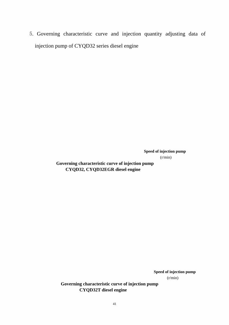
5. Governing characteristic curve and injection quantity adjusting data of
injection pump of CYQD32 series diesel engine
Speed of injection pump (r/min)
Governing characteristic curve of injection pump CYQD32, CYQD32EGR diesel engine
Speed of injection pump
(r/min) Governing characteristic curve of injection pump
CYQD32T diesel engine
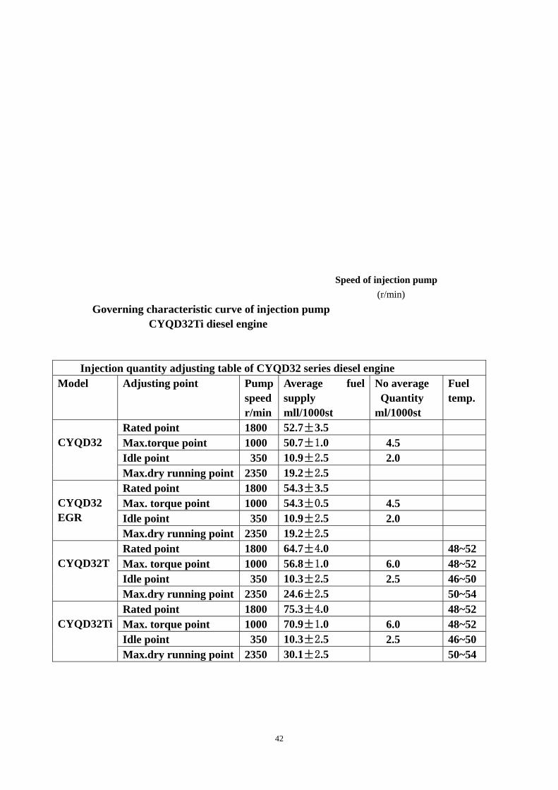
42
Speed of injection pump
(r/min) Governing characteristic curve of injection pump
CYQD32Ti diesel engine
Injection quantity adjusting table of CYQD32 series diesel engine Model Adjusting point Pump
speed r/min
Average fuel supply mll/1000st
No average Quantity ml/1000st
Fuel temp.
Rated point 1800 52.7±3.5 Max.torque point 1000 50.7±1.0 4.5 Idle point 350 10.9±2.5 2.0
CYQD32
Max.dry running point 2350 19.2±2.5 Rated point 1800 54.3±3.5 Max. torque point 1000 54.3±0.5 4.5 Idle point 350 10.9±2.5 2.0
CYQD32 EGR
Max.dry running point 2350 19.2±2.5 Rated point 1800 64.7±4.0 48~52 Max. torque point 1000 56.8±1.0 6.0 48~52 Idle point 350 10.3±2.5 2.5 46~50
CYQD32T
Max.dry running point 2350 24.6±2.5 50~54 Rated point 1800 75.3±4.0 48~52 Max. torque point 1000 70.9±1.0 6.0 48~52 Idle point 350 10.3±2.5 2.5 46~50
CYQD32Ti
Max.dry running point 2350 30.1±2.5 50~54

43
Chapter Ⅶ Auxiliary System of Diesel Engine
A. Lubrication system
Lubrication system diagram is as following:
----------------------- --- - - ----------------------------------------- oil passage
------ by passage main oil gallery -..-..-.. through oil sump
------- -------------------------------------------
Oil sump
Filter oil screen
Oil pump
Oil filter
Oil cooler
Safe valve
By—pass valve
By pass valve
Equalizer
valve
Main oilgallery idler
Main bearing
crankshaft
Connecting rodbearing
timing gear Piston
Cooling injector
Camshaft bearing
tappet
Push rod
Cylinder head
Rocker seat
Rocker arm shaft
rocker
Vacuum-pump

44
Lubrication system maintenance:
The oil level in oil pan must be checked before engine starting. The oil level
must be within the two marks of oil dipstick. The changing and cleaning of oil and
filter element is done according to the requirements.
The maintenance of lubrication system is done timely, and the more
thoroughly the better, because it may help our customers to use engine reliably and
to operation in long term with satisfactory.
Close attention must be paid to pressure gauge during operation, the oil
pressure is 196~490kPa (2~5kgf/cm2) in normal operation, and over 98 kPa
(1kgf/cm2) in idling operation.
B. Cooling system
The closing system is close forced circulation water cooling type. Water
temperature in cooling system is kept about 85℃.Low temperature will lead to
wear of engine. High temperature will lead to be abnormal operation or failures.
1. Flow direction of coolant:
Water flows out from water pump outlet to the right side of engine block, cools
the oil cooler at first then flows into cylinder water jacket and cylinder head, from
there goes into the thermostat installed in the front of cylinder head. The holes of
cooling water in cylinder head and engine block are made casting and drilling.
Some holes are small, therefore close attention must be paid to be restricted,
especially care to the cooling water jet for cooling the triangle area among valves

45
and nozzle, or it leads to overheat in this area and damage the fuel injector.
Therefore, we especially recommend our customer to use long-term effective
coolant, otherwise it may cause troubles.
2. Water pump is centrifugal type:
When water seals break down, coolant will leak from the overflow hole, so it
must be repaired timely.
3. Thermostat
The opening temperature of thermostat is 76.5℃. When the thermostat is
closed, it makes a small cycle and the water coming out from the cylinder head will
all flow back into the water pump. When water temperature reaches or rises 90℃,
makes a big cycle, all water flows into radiator and cools there. Thermostat cannot
be removed under any condition.
4. Cooling system maintenance:
In normal operation, must use long-term effective coolant. Besides, if found
leakage in cooling system, please clean it as per the following method:
Clean agent was made by mixing 150g sodium hydroxide ( NaOH) with 1 liter
water. Before cleaning, drain out the coolant from the cooling system first, then
pour into the equal cleaning agent, stay 8~12 hours, then make engine operation.
After the temperature reached the working temperature, stop the engine and drain

46
out cleaning agent immediately in order to avoid floating scale deposited there, at
last clean cooling system with cleaning water.
Checking the water level in radiator every time before vehicle is in operation or
go back the parking place, refilling to the specified level when it’s insufficient.
Checking and maintaining the belt tension of the water pump regularly, which is
adjusted by alternator bracket and tensioner. When the belt is pressed by 29~39N
(3~4kgf) force, the deflection of single belt should be between 10~15 mm, neither
too tight nor too loose.
5. Silicone oil fan clutch:
CYQD32 series diesel engine is using silicone oil fan clutch. The silicone oil
fan clutch is installed between driving shaft and fan. You can base on the
requirement of engine cooling system, control the speed of fan and adjust the
strength of cooling. Compared with conventional rigid fixed fan, the main
advantages of the cooling system with silicone oil fan clutch are as followings: save
energy, reduce noise, low emission and less wear etc.
CYQD32 series diesel engine is integrated water pump with clutch, the basic
contour is shown as figure. The water
pump and clutch are fixed on a driving
shaft, as a complete part, the advantages
are: proper in space layout, less run-out
in concentric,good in dynamic balance,
long service life.

47
C: Auxiliary system
1. Vacuum pump
Vacuum pump is driven by injection pump gear directly.
Flow rate of vacuum pump (cm3/rev) 60
Gear number of vacuum pump 39
Negative pressure when idling (reference)
kpa(mmHg)
-87 (-650) above
2. Starter:
Use starter with two axial decrease speed:
Model S14-205
Power 12 V-2.8 kW
3. Alternator:
The standard setup rated output: 12V, 70A. On request, it also can use alternator
with 14V, 90A or 14V, 120A .
D. Clutch
The engine can match clutch with friction disc diameter of ф260mm orф
275mm according to the customer’s requirement. The engine doesn’t equip with

48
gearbox and operation mechanism. The clutch is only given a preliminary
adjustment before delivery, customer needs to readjust it when it is installed in
vehicle or in operation.
E. Preheating device
There is a preheating device in the engine, the heating part of the glow plug
heats the air by penetrating into the pre-combustion chamber, hence ensure the
diesel engine start smoothly under lower temperature.
A. Instruction of glow plug
1. The rated voltage of glow plug: dc 11±0.1V, the working voltage of
glow plug must be same as the voltage of accumulator.
2. Current characteristic of glow plug: under rated voltage, the working
current of glow plug after electrified for 20S should be ≤10A, the
sustained working current (60S) should be ≤8A.
3. When connecting end of the glow plug is wired, the tighten torque of
the nut is ≤7N.m.
4. The preheating time is more than 20 seconds and less than 60 seconds,
it will influence the service life of glow plug assembly if the heating
time is too long.
5. Change the glow plug assembly in time in case the head of it was
damaged, otherwise, it’s easy to cause short circuit of it.
6. Prevent electric conducting plate from contact with the nearby object,
to avoid burning electric system because of short circuit.

49
B. Instruction of preheating device:
The preheating device consists 4 glow plugs, 1 electric conducting plate, 1
wiring harness and 1 preheating electronic control accompanied with the
engine. According to the different requirement of vehicle setup, the
working principle of the preheating electronic control accompanied with
the engine and the type of insert parts are also different, generally there
are two kinds of them:
One is a wiring diagram of the preheating electronic control, type DKK
1507, shown as below figure. This preheating electronic control is used
with electronic fan, it has low speed relay and high speed relay. The
setting temperature of low speed and high speed relays correspond with
the operation temperature of low speed and high speed fan.
Wiring Diagram
50
1. Please connect the wire strictly follow the wiring diagram, especially
pay attention to the connection of positive/negative power supply,
otherwise, the electronic device can’t work properly and may be
damaged due to this reason.
2. When starts the engine, the preheating lamp start to light after the key
switch is turned on .The engine can start only the preheating lamp is
off. If the key switch is turned to Start position, but the engine still
doesn’t start within 15±3 seconds, the electronic device will cut off
the circuit automatically; If want to start again with preheating, then
must turn off the key switch for about 3 seconds, then repeat the above
procedure.
3. During post preheating, the low speed relay will be on if the coolant
temperature is above 86℃; the high speed relay will be on if the
coolant temperature is above 93℃.
4. In order to protect your engine and benefit, in cold whether, we
strongly recommend to start the engine only when the front preheating
lamp is off.
5. Note: must use a post preheating glow plug that matching this device.
The function of every pin in below DJ7121 y-2.2-20 connectors are as
following:

51
Match DJ7121 y-2.2-20 connectors
1. Connect to start shift of key switch (ST)
2. Connect to D + signal
3. Connect to preheating indicating lamp
4. Connect to the negative pole of accumulator
5. Connect to temperature sensor
6. Connect to vehicle speed sensor
7. Connect to working shift of the key switch (ON)
8. Connect to preheating relay of glow plug (matching with 70A/14VDC)
9. No connection
10. Connect to low speed relay
11. Connect to high speed relay
12. Connect to overflow valve (KSB valve)
Another type is a preheating electronic control that matching with normal fan,
such preheating electronic control has no low speed relay and high speed relay.
Note:
1. The way of connection and connector type for different type of preheating
electronic control may different.
2. In order to avoid improper working of the preheating electronic control,
when customer change temperature sensor and vehicle speed sensor, please
chose the same product from the same manufacturer that same as original
one.

52
F. Idling increasing device
A idling increasing control and its control electromagnetic valve are installed on
injection pump of the engine. The function of an idling increasing control is:
when turn on air condition when engine is under idling mode (700 ± 50r/min),
the electromagnetic valve of the idling increasing control is in operation, pull the
fuel filling handle move a certain distance torwards fuel filling direction, allow
the idle of engine increased to 850 ± 50r/min in order to increase the
generated energy of the alternator to fulfill the requirement of air condition.
Idling increasing device

53
Chapter Ⅷ Trouble and shooting of Diesel Engine
A. Difficult to Start
1.Starter Doesn’t Run
Mainly Check Reasons Remedy
Starting switch NG→ poor contact, damage → repair, replace ok↓ fuse NG→ melt → replace ok↓ storage battery NG→ poor contact caused by ↓ terminal loose, corrosion→ clean and tight
↓ NG→ not full charged, poor discharge→ repair charging system charge or replace
ok↓ NG→ fan belt loose, damage → tension, replace starter NG→ poor magnetic switch → repair and replace NG→ poor starter → repair and replace
2.Starter Runs But Engine Doesn’t Run
storage battery NG→ poor contact caused by ↓ terminal loose, corrosion→ clean and tight ↓ NG→ not full charged, poor discharge→ repair charging system
charge or replace ↓ NG→ fan belt loose, damage
( influence the alternator) → tension, replace ok↓ starter NG→ small gear or gear ring damaged→ replace ↓ NG→ brush worn, brush spring broken→ clean and tight ↓ NG→ magnetic switch damaged → repair, replace ok↓
engine itself NG→ internal moving parts damaged, melt, such as piston, main shell→ repair, replace

54
3. Starter Runs But Engine Doesn’t Work * Injection Pump Stop to Supply Mainly Check Reasons Remedy
Engine stop whether the solenoid valve of injection mechanism NG→ pump is connected to the power supply→ check & adjusting ok↓ fuel tank NG→ no fuel → filling ok↓ fuel pipe NG→ blocked, damaged, loose in connection part → repair, replace
and tight ok↓ fuel filter NG→ overflow valve can’t close→ repair, replace ↓ NG→ filter element blocked → replace ok↓ fuel system NG→ mixed with air in fuel system→ release air NG→ inlet screen blocked in Fuel supply pump → clean and repair
NG→ fuel supply pump doesn’t Work properly → repair, replace * Injection pump supply fuel
Fuel NG→ poor quality or incorrect brand→ replace ↓ NG→ water in fuel → replace
ok↓ fuel system NG→ air in fuel system → release air ok↓ advance angle NG→ incorrect advance angle → adjusting ok↓
injector NG→ injector assembly blocked leaking → replace ↓ NG→ opening pressure is low → adjust and replace
ok↓ injection pump NG→ poor delivery valve, blocked→ repair, replace ↓ NG→ plunger worn or blocked → repair, replace ok↓
compressed pressure NG→ cylinder bore worn, piston ring blocked or broken → repair, replace NG→ valve leaking → repair, replace

55
B.Idle Speed Is Unstable Mainly Check Reasons Remedy
Fuel system NG→ leaking in fuel system → repair, replace ↓ NG→ mixed with in fuel system → release air ↓ NG→ water in fuel → replace
ok↓ fuel filter NG→ filter element blocked → clean, replace ok↓ injector NG→ injector assembly blocked, leak→ adjust, replace ↓NG→ opening pressure low, poor injection→ adjust, replace ok↓ fuel pump NG→ idle speed is too low → adjust, replace
↓ NG→ oil is uneven in each cylinder → adjust, repair ,replace ↓ NG→ poor delivery valve, blocked → adjust, repair, replace ↓ NG→ plunger worn and its spring broken→ replace ↓ NG→ camshaft worn, tappet worn → replace
ok↓ engine itself NG→ valve gap incorrect → adjusting ↓ NG→ poor valve and valve seat seal → repair, replace ↓ NG→ cylinder bore worn, piston ring
blocked or broken → repair, replace
C. Insufficient Power
Air filter NG→ filter element blocked → clean and replace
ok↓ fuel system NG→ mixed air in fuel system → release air ↓ NG→ oil circuit blocked → clean, repair, replace
ok↓ oil gate mechanism NG→ the lever is not in position
fuel supply is insufficient → adjust, repair ok↓
advance angle NG→ advance angle is incorrect → adjusting ok↓
fuel pump→NG main spring of governor adjust, replace ↓ NG→ plunger, camshaft or tappet worn→ replace
ok↓ turbocharger NG→ gas guide pipe of boost compensator
crack → repair, replace

56
↓ NG→ too much dirt in intake/exhaust manifold or leak air in connection → clean, repair, replace ↓ NG→ performance of turbocharger reduced→ clean, repair, replace
inter-cooler NG→ leak in pipe, dirt cause big resistance → repair, replace ok↓
injector NG→ poor spray of injector or blocked → adjust, replace ok↓
engine itself NG→ valve gap is incorrect → adjust ↓ NG→ poor sealing in valve, valve seat → repair, replace ↓ NG→ cylinder bore worn, piston ring blocked
or broken → repair, replace ↓ NG→ the gasket of the head is breakdown→ replace
D. Fuel Consumption Is Big
Fuel system NG→ leaking in fuel system → repair, replace
ok↓ air filter NG→ filter element blocked → clean, replace
ok↓ advance angle NG→ advance angle is incorrect → adjusting ok↓ injector NG→ poor spray of injector → adjust, replace ok↓ turbocharger NG→ too mush dirt in intake/exhaust
manifold or leak air in connection→ repair, replace ↓ NG→ poor performance of turbocharger→ clean, adjust, replace
ok↓ engine itself NG→ valve gap is incorrect → repair, replace ↓ NG→ not well sealed in valve, valve seat → adjust, replace ↓ NG→ valve spring became soft → replace ↓ NG→ cylinder bore worn, piston ring blocked
or broken → repair, replace
E. Oil Consumption Is Big Mainly Check Reasons Remedy
57
turbocharger NG→ failure of turbine end sealing or compressor blade end sealing → repair, replace
ok↓ valve seal NG→ failure of valve guide seal → repair, replace
ok↓ in/ex. Valve NG→ valve stem and guide is worn→ replace
ok↓ bore, ring NG→ cylinder bore worn, piston ring blocked
or broken → repair, replace ok↓
whole oil system NG→ leaking → repair, replace
F. Water Temperature Is High in Engine Outlet Cooling water tank NG→ coolant is not enough → filling ↓ NG→ radiator is blocked → clean ↓ NG→ cover of water tank damaged→ repair, replace
ok↓ water tank meter
or water tem. sensor NG→ failure → repair, replace ok↓
fan belt NG→ loose or damaged → tension, replace ok↓
water pump NG→ water pump damaged → repair, replace ↓ NG→ silicone oil clutch failed → repair, replace ok↓ thermostat NG→ failure, damaged → replace ok↓ seal between head and block NG→ gasket failure, water flow→ replace ok↓ cooling passage NG→ too mush scale, blocked → remove ok↓ advance angle NG→ too small, seriously rear fire→ adjusting
G. White Smoke in Exhaust Mainly Check Reasons Remedy

58
advance angle NG→ too small, seriously rear fire→ adjusting
ok↓ fuel NG→ water n fuel → replace ok↓
injector NG→ poor spray of injector, leak → adjust, repair, replace ok↓
turbocharger NG→ turbocharger damaged → repair, replace ok↓ in/ex. valve NG→ valve worn or damaged → replace ↓ NG→ failure of guide seal → replace ok↓ bore, ring NG→ cylinder bore worn, piston ring blocked or broken → replace
H. Black Smoke in Exhaust
Air filter NG→ filter element blocked → clean, replace ok↓ advance angle NG→ too big or too small → adjusting ok↓ injector NG→ poor spray of injector, leak → adjust, repair, replace ↓ NG→ opening pressure is low of it→ adjust, replace
ok↓ turbocharger NG→ doesn’t work properly → check, repair, replace
I. Oil Pressure Is Low
Mainly Check Reasons Remedy
Oil manometer or pressure sensor NG→ damaged → replace ok↓ oil NG→ oil brand is not correct → replace
ok↓ oil filter NG→ filter element blocked → replace ok↓

59
safety valve/ bypass valve NG→ spring damaged or valve
body blocked → repair, replace ok↓
oil pump NG→ gear was worn → replace ok↓ rocker shaft NG→ rocker shaft was worn → replace ok↓ camshaft &bush NG→ they were worn → replace
ok↓ crankshaft, con’rod and shell NG→ they were worn → replace
ok↓ oil cooler NG→ cooler element blocked → clean, replace
↓ NG→ opening pressure of the bypass valve is incorrect→ check,, adjust, replace
J. Failure caused by Turbocharger
1. Power is insufficient
* Black Smoke in Exhaust
Mainly Check Reasons Remedy
Turbocharger speed Is insufficient NG→ impurity of oil piled up at side
Seal of turbine → replace oil, repair turbocharger ↓ NG→ oil tem. is too high, oil is insufficient floating bearing burnt → check oil system, repair
turbocharger ↓ NG→ rotor of turbine shaft is out of balance→ repair, replace
ok↓ friction between turbine blade and compressor blade, damaged NG→ turbine speed is too high → check boost system, repair
↓ NG→ exhaust tem., pressure is too high→ check engine, repair ↓ NG→ mixed with foreign matter → check intake system, repair, replace

60
↓ NG→ floating bearing was worn → replace
* White Smoke in Exhaust
Oil return pipe Of turbocharger NG→ oil leaks from turbine and compressor Shaft end caused by block and deform.→ repair, replace
ok↓ seal ring NG→ damaged → replace
2. Oil Consumption is Too Big seal ring NG→ worn, damaged → replace ok↓
oil NG→ poor quality → replace ok↓
leak from blade end of compressor NG→ air filter blocked → clean, replace ↓ NG→ dynamic balance of turbine is poor → replace
3. Abnormal Sound turbine end NG→ gas passage became too small → clean, replace
ok↓ compressor end NG→ gas passage became too small → clean, replace ↓ NG→ when countercurrent produced in gas outlet → repair, replace
ok↓ friction between turbine, compressor blade and case NG→ floating bearing worn too much → replace

61
4.Vibration
Mainly Check Reasons Remedy friction between turbine, compressor
blade and case NG→ foreign matter entered → replace ↓ NG→ floating bearing worn too much → replace
↓ NG→ dynamic balance of turbine is poor→ check, repair, replace
↓ NG→ dynamic balance of turbine is poor→ replace

62
Meaning of the Unit Symbols Used
in This Manual and Its Conversion
item Unit symbols Conversion
power kW 1 kW=1.36 Ps
torque N.m 1 kgf.m=9.81 N.m
speed R/min
Oil/fuel
consumption
G/kW.h 1 g/Ps=1.36 g/kW.h
Swept volume L 1 L=1000 ml
area Cm2 1 m2 =10000 cm2
pressure KPa
MPa
1 kgf/ cm2=98.1
kPa=0.0981 Mpa
force N 1 kgf=9.8 N
length m 1 m=1000m
time Min(s) 1 min=60 s
temperature K(ºC) 273 K=0 (ºC)
voltage V
current A
Crankshaft
angle
ºCA
mass g 1 kg=1000 g

63
CYQD32Ti turbo-charge inter-cooling diesel engine Full speed &full load characteristic curve Model CYQD32 diesel engine
Full speed &full load characteristic curve Model CYQD32EGR diesel engine
Full speed &full load characteristic curve Model CYQD32T diesel engine
Full speed &full load characteristic curve Model CYQD32Ti diesel engine
P10 pulley of fan deflection pulley of alternator pulley of crankshaft
p19 correct spray no good no good no good no good no good P14 engine cylinder intercooler compressed air flow exhaust gas outlet
ambient air inlet exhaust gas flow
p16 accelerator handle idle screw gone out device(red wire) start become thicker(black wire)
p22 high speed relay low speed relay charge indicator alternator
preheating lamp key switch preheat relay glow plug vehicle speed sensor temperature sensor overflow valve
p24 HP pump accelerating handle pipe connecting to vacuum pump terminal 1 solenoid valve terminal 2 connecting hose 1 connecting hose 2 idle increasing device
p44 accelerator full open position idle position accelerator full open position idle position average fuel supply average fuel supply average fuel supply


![V-Demethylation of the Antineoplastic Agent … · [CANCER RESEARCH 33, 2810 2815, November 1973] /V-Demethylation of the Antineoplastic Agent Hexamethylmelamine by Rats and Man1](https://static.fdocuments.in/doc/165x107/5f081bda7e708231d4206171/v-demethylation-of-the-antineoplastic-agent-cancer-research-33-2810-2815-november.jpg)