QCVN 07:2010/BTTTT QUY CHU ẨN KỸ THUẬT QUỐC GIA VỀ...
29
Soc Q QUY C VỀ GIAO DIỆN Q Na on optical interface relating to 1 cialist Republic of Viet Nam QCVN 07:2010/BTTTT CHUẨN KỸ THUẬT QUỐC GIA QUANG CHO THIẾT BỊ KẾT NỐI SDH ational technical regulation es for network interconnection equ the Synchronous Digital Hierarchy (for information only) HA NOI - 2010 I MẠNG uipments y
Transcript of QCVN 07:2010/BTTTT QUY CHU ẨN KỸ THUẬT QUỐC GIA VỀ...

Socialist Republic of Viet Nam
QCVN
QUY CHUVỀ GIAO DIỆN QUANG CHO THIẾT BỊ KẾT NỐI MẠNG
National technical regulation on optical interfaces
relating to the Synchronous Digital Hierarchy
1
Socialist Republic of Viet Nam
QCVN 07:2010/BTTTT
QUY CHUẨN KỸ THUẬT QUỐC GIA ỆN QUANG CHO THIẾT BỊ KẾT NỐI MẠNG
SDH
National technical regulation
al interfaces for network interconnection equipments relating to the Synchronous Digital Hierarchy
(for information only)
HA NOI - 2010
ẨN KỸ THUẬT QUỐC GIA ỆN QUANG CHO THIẾT BỊ KẾT NỐI MẠNG
for network interconnection equipments relating to the Synchronous Digital Hierarchy

QCVN 7:2010/BTTTT
2
Table of contents
Foreword 3
1. General 5
1.1. Scope 5
1.2. Objectives 5
1.3. Definitions 5
1.4. Abbreviations 8
2. Technical requirements 9
2.1. General requirements 9
2.2. Optical interface parameters for SDH systems without using optical amplifier
11
2.3. Optical interface parameters for SDH systems using optical amplifier
19
3. Regulation on management 24
4. Responsibility of organistions/individuals 24
5. Implementation 24
Annex A (normative) – Eye-mask measurement method for optical transmit signals
25
Annex B (normative) – Relations between optical parameters 27
Annex C (normative) – Dispersion accomodation (DA) method 28

QCVN 7:2010/BTTTT
3
Foreword
QCVN 07:2010/BTTTT is based on ITU Rec. G.691, G.693, G.957, G.958, G.959.1.
QCVN 07:2010/BTTTT is drafted by Research Institute of Posts and Telecommunications (RIPT), verified and submitted by Department of Science & Technology, Ministry of Information and Communications issued as in Circular No. 18/2010/TT-BTTTT dated 30/7/2010.

QCVN 7:2010/BTTTT
4

QCVN 7:2010/BTTTT
5
QUY CHUẨN KỸ THUẬT QUỐC GIA
VỀ GIAO DIỆN QUANG CHO THIẾT BỊ KẾT NỐI MẠNG SDH
National technical regulation on optical interfaces for network interconnection equipments relating to the
Synchronous Digital Hierarchy
1. GENERAL
1.1. Scope
This technical regulation defines physical and electrical characteristics of the interfaces at hierarchical bit rates (64 kbit/s, 2048 kbit/s, 34368 kbit/s, 139264 kbit/s, 155520 kbit/s and 2048 kbit/s synchronous interfaces) to enable the interconnection of digital network components (digital sections, multiplex equipment, exchanges) to form an international digital link or connection.
1.2. Objectives
This technical regulation applies to telecommunication companies for establishing and providing services when they are in negotiating for network connecting with others via SDH optical interconnection equipments.
1.3. Tài liệu viện dẫn
1. ITU-T Recommendation G.957 (2006) Optical interfaces for equipments and systems relating to the synchronous digital hierarchy.
2. ITU-T Recommendation G.691 (2006) Optical interfaces for single channel SDH systems with optical amplifiers, and STM-64 systems.
3. ITU-T Recommendation G.959.1 (2003), Optical transport network physical layer interfaces.
4. ITU-T Recommendation G.693 (2005), Optical interfaces for intra-office systems.
5. ITU-T Recommendation G.651 (02/98) Characteristics of a 50/125 µm multimode graded index optical fibre cable.
6. ITU-T Recommendation G.652 (06/05) Characteristics of a single-mode optical fibre and cable.
7. ITU-T Recommendation G.653 (12/03) Characteristics of a dispersion-shifted single-mode optical fibre and cable.
8. ITU-T Recommendation G.654 (06/04) Characteristics of a cut-off shifted single-mode optical fibre and cable.
9. ITU-T Recommendation G.655 (03/06) Characteristics of a non-zero dispersion-shifted single-mode optical fibre and cable.
10. ITU-T Recommendation G.656 (06/04) Characteristics of a fibre and cable with non-zero dispersion for wideband optical transport.
1.4. Definitions

QCVN 7:2010/BTTTT
6
1.4.1. Standard configuration of optical interface
- Systems without using optical amplifier:
Figure 1 - Standard configuration of optical interface for systems without using optical amplifier
Optical interface characteristics in the transmitter are specified at S point (reference point on the fiber, right behind connector in transmitter), and in the receiver are specified at R point (reference point on the fiber, right front connector in receiver) and main path is between S and R.
- Systems using optical amplifier:
Figure 2 - Standard configuration of optical interface for systems using optical amplifier
Optical interface characteristics are specified at MPI-S point in the transmitter and MPI-R point in the receiver, and main path is between MPI-S and MPI-R.
1.4.2. Spectral width
- RMS width: for LED and MLM, spectral width is in maximum rms in normal operating conditions. RMS width is measured with all modes which are equal or greater than peak mode of 20 dB.
- -20 dB width: for SLM, width is calculated by maximum width of radiated spectrum at central frequency measured at the level of 20dB lower in comparasion with maximum amplitude of central frequency in normal operating conditions.
1.4.3. Side mode suppression ratio
Side mode suppression ratio is the ratio between maximum and 2nd peak power in the spectrum of the transmitter.
MPI-S MPI-R Tx OA OA
Transmitter Receiver
Rx
S R
CTX
CRX
Fiber
Transmitter
Optical connectorin transmitter
Optical connector in receiver
Receiver

QCVN 7:2010/BTTTT
7
1.4.4. Mean lauched power
Mean lauched power at S point (or MPI-S point) is mean power of pseudo-random chain which transmitter injected to fiber. This value is used for calculation of sensitivity and overload of receiver at R point (or MPI-R) (see Annex B).
1.4.5. Extinction ratio
Extinction ratio (EX) is calculated by the following equation:
EX = 10 lg (A/B)
In which: - A is mean optical power for “1” logical level;
- B is mean optical power for “0” logical level.
1.4.6. Attenuation range
Attenuation range is calculated in severe circumstances, including attenuation of weld connections, connectors, attenuators (if any), or other passive optical components and any compensation powers for:
- future changes in cable configuration (adding weld connections, cable length changes...);
- fiber quality changes because of environmental impacts;
- degradation of connectors, attenuators or other passive optical components between S and R (or MPI-S and MPI-R).
1.4.7. Maximum chromatic dispersion
Maximum chromatic dispersion is maximum chromatic dispersion value of main path that can be accepted by system when no dispersion accomodation method applied.
1.4.8. Polarization mode dispersion
Polarization mode dispersion is time deviation of group delay τp (in ps) between 2 orthogonal polarization modes.
1.4.9. Differential group delay
Differential group delay is the diference in time between pulses propagate in 2 main polarizations of an optical signal.
Maximum differential group delay is differential group delay value that the system can sustain with 1 dB degradation in signal intensity.
1.4.10. Optical return loss of cable plant at S/MPI-S
Optical return loss of cable plant at S/MPI-S (ORL) is calculated as following:
ORL = -10 lg (P’s/Ps)
In which: - P’s is feedback power to transmitter measured at S/MPI-S;
- Ps is power injected to the fiber at S/MPI-S.
1.4.11. Receiver sensitivity
Receiver sensitivity is minimum mean receiving power at R point (or MPI-R) to achieve:

QCVN 7:2010/BTTTT
8
- BER = 10-10 for STM-1, STM-4, STM-16 systems without using OA.
- BER = 10-12 for STM-64 and other systems using OA.
1.4.12. Receiver overload
Receiver overload is maximum mean power acceptable at R point (or MPI-R) to achieve:
- BER = 10-10 for STM-1, STM-4, STM-16 systems without using OA.
- BER = 10-12 for STM-64 and other systems using OA.
1.4.13. Optical path power penalty
Optical path power penalty is sensitivity degradation value because of signal distortion propagating on the fiber. Signal distortion is by emisions, interferences between symbols, mode competitions and frequency-hops of laser.
1.4.14. Receiver reflectance
Receiver reflectance is versa reflectance from receiver to the fiber, and is calculated as following:
R = 10 lg (P’R/PR)
In which:
- P’R is feedback power to the fiber measured at R/MPI-R;
- PR is power to the receiver at R/MPI-R.
1.4. Abbreviations
APD Avalanche photodiode
BER Bit Error Ratio
DA Dispersion Accommodation
DST Dispersion Supported Transmission
EX Extinction ratio
LED Light-Emitting Diode
MLM Multi-Longitudinal Mode
MPI Main Path Interface
NA Not Applicable
NC Not Comformable
NRZ Non-Return to Zero
OA Optical Amplifier
ORL Optical Return Loss
PCH Prechirp
PDC Passive Dispersion Compensator
PIN "p-type" – intrinsic – "n-type"
PMD Polarization Mode Dispersion
RMS Root Mean Square

QCVN 7:2010/BTTTT
9
Rx Receiver
SDH Synchronous Digital Hierarchy
SLM Single-Longitudinal Mode
SMSR Side Mode Suppression Ratio
SPM Self Phase Modulation
Tx Transmitter
UI Unit Interval
2. TECHNICAL REQUIREMENTS
2.1. General requirements
2.1.1. Technical parameters
Parameters specified in this technical regulation are all calculated in severe circumstances with standard operation conditions of equipments (i.e, temperature, humidity conditions) and lifetime acceleration effects to achieve:
- BER = 10-10 for STM-1, STM-4, STM-16 systems without using OA;
- BER = 10-12 for STM-64 and other systems using OA.
2.1.2. Classification of optical interfaces
Classification of optical interfaces define in Table 1. Target distances of application codes were chosen basing on parameters of existing technologies and networks.

QC
VN
7:2
010/
BT
TT
T
10
Tab
le 1
– C
las
sifi
cat
ion
of
op
tica
l in
terf
aces
bas
ed o
n a
pp
lica
tio
n
Applic
ations
I S
L
V
U
Wave
len
gth
, N
m
1 3
10
1 3
10
1 5
50
1 5
50
1 3
10
1 5
50
1 5
50
1 3
10
1 5
50
1 5
50
1 5
50
1 5
50
Fib
er
typ
e
G.6
52
G.6
52
G.6
52
G.6
53
G
.652
G
.652/
G.6
54
G.6
53
G.6
52
G.6
52/
G.6
54
G.6
53
G
.652/
G.6
54
G.6
53
Tar.
D
ista
nce,
km
~2
~15
~15
- ~
40
~
80
~
80
~
80
~120
~
120
~160
~160
ST
M-1
I-
1
S-1
.1
S-1
.2
- L-1
.1
L-1
.2
L-1
.3
- -
- -
-
ST
M-4
I-
4
S-4
.1
S-4
.2
- L-4
.1
L-4
.2
L-4
.3
V-4
.1
V-4
.2
V-4
.3
U-4
.2
U-4
.3
ST
M-1
6
I-16
S-1
6.1
S
-16.2
-
L-1
6.1
L-1
6.2
L-1
6.3
V-1
6.2
V
-16.3
Tar.
dis
tance,
km
ST
M-6
4
~
20
S-6
4.1
~40
S-6
4.2
~40
S-6
4.3
~40
L-6
4.1
~80
L-6
4.2
~80
L-6
4.3
~80
V-6
4.1
~120
V-6
4.2
~120
V-6
4.3
- -
NO
TE
: T
arg
et dis
tance
are
to b
e u
sed f
or
cla
ssific
ations a
nd n
ot
for
specific
ations.

11
System codes in Table 1: Application – STM level. suffix
- Applications are including I, S, L, V (I is application for communication in 1 station; S, L, V, U are applications for communication between stations).
+ I (Intra office): connecting in one station or between stations (distance between 0,6 -25 km);
+ S (Short haul) (20 - 40 km);
+ L (Long haul) (40 - 80 km);
+ V (Very long haul) (60 - 120 km);
+ U (Ultra long haul) (120 - 160 km).
- Suffix are:
+ Empty or “1” for systems operating in the wavelength of 1310 nm on G.652 fiber;
+ “2”: for systems operating in the wavelength of 1550 nm on G.652 or G.654 fiber;
+ “3”: for systems operating in the wavelength of 1550 nm on G.653 fiber.
2.2. Optical interface parameters for SDH systems without using optical amplifier
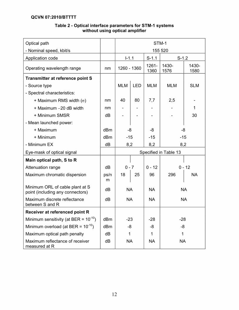
2.2.1. STM-1 systems
Optical interface parameters for STM-1 systems without using optical amplifier are specified in Table 2 and 3.
QCVN 07:2010/BTTTT
12
Table 2 - Optical interface parameters for STM-1 systems without using optical amplifier
Optical path STM-1
- Nominal speed, kbit/s 155 520
Application code I-1.1 S-1.1 S-1.2
Operating wavelength range nm 1260 - 1360 1261-1360
1430-1576
1430-1580
Transmitter at reference point S
- Source type MLM LED MLM MLM SLM
- Spectral characteristics:
+ Maximum RMS width (σ) nm 40 80 7,7 2,5 -
+ Maximum −20 dB width nm - - - - 1
+ Minimum SMSR dB - - - - 30
- Mean launched power:
+ Maximum dBm -8 -8 -8
+ Minimum dBm -15 -15 -15
- Minimum EX dB 8,2 8,2 8,2
Eye-mask of optical signal Specified in Table 13
Main optical path, S to R
Attenuation range dB 0 - 7 0 - 12 0 - 12
Maximum chromatic dispersion ps/nm
18 25 96 296 NA
Minimum ORL of cable plant at S point (including any connectors)
dB NA NA NA
Maximum discrete reflectance between S and R
dB NA NA NA
Receiver at referenced point R
Minimum sensitivity (at BER = 10-10) dBm -23 -28 -28
Minimum overload (at BER = 10-10) dBm -8 -8 -8
Maximum optical path penalty dB 1 1 1
Maximum reflectance of receiver measured at R
dB NA NA NA

QCVN 07:2010/BTTTT
13
Table 3 - Optical interface parameters for STM-1 systems without using optical amplifier (cont.)
Optical path STM-1
- Nominal speed, kbit/s 155 520
Application code L-1.1 L-1.2 L-1.3
Operating wavelength range nm 1263 - 1360
1480-1580
1534-1566/
1523-1577
1480-1580
Transmitter at reference point S
- Source type MLM SLM SLM MLM SLM
- Spectral characteristics:
+ Maximum RMS width (σ) nm 3 - - 3/2,5 -
+ Maximum −20 dB width nm - 1 1 - 1
+ Minimum SMSR dB - 30 30 - 30
- Mean launched power:
+ Maximum dBm 0 0 0
+ Minimum dBm -5 -5 -5
- Minimum EX dB 10 10 10
Eye-mask of optical signal Specified in Table 13
Main optical path, S to R
Attenuation range dB 10 - 28 10 - 28 10 - 28
Maximum chromatic dispersion ps/nm
246 NA NA 246/296 NA
Minimum ORL of cable plant at S point (including any connectors)
dB NA 20 NA
Maximum discrete reflectance between S and R
dB NA -25 NA
Receiver at referenced point R
Minimum sensitivity (at BER = 10-10) dBm -34 -34 -34
Minimum overload (at BER = 10-10) dBm -10 -10 -10
Maximum optical path penalty dB 1 1 1
Maximum reflectance of receiver measured at R
dB NA -25 NA

QCVN 07:2010/BTTTT
14
2.2.2. STM-4 systems
Optical interface parameters for STM-4 systems without using optical amplifier are specified in Table 4 and 5.
Table 4 - Optical interface parameters for STM-4 systems without using optical amplifier
Optical path STM-4
- Nominal speed, kbit/s 622 080
Application code I-4 S-4.1 S-4.2
Operating wavelength range nm 1261 - 1360
1293-1334/
1274 -1356
1430 - 1580
Transmitter at reference point S
- Source type MLM LED MLM SLM
- Spectral characteristics:
+ Maximum RMS width (σ) nm 14.5 35 4/2.5 -
+ Maximum −20 dB width nm - - - 1
+ Minimum SMSR dB - - - 30
- Mean launched power:
+ Maximum dBm -8 -8 -8
+ Minimum dBm -15 -15 -15
- Minimum EX dB 8,2 8,2 8,2
Eye-mask of optical signal Specified in Table 13
Main optical path, S to R
Attenuation range dB 0 - 7 0 – 12 0 - 12
Maximum chromatic dispersion ps/nm 13 14 46/74 NA
Minimum ORL of cable plant at S point (including any connectors)
dB NA NA 24
Maximum discrete reflectance between S and R
dB NA NA -27
Receiver at referenced point R
Minimum sensitivity (at BER = 10-10) dBm -23 -28 -28
Minimum overload (at BER = 10-10) dBm -8 -8 -8
Maximum optical path penalty dB 1 1 1
Maximum reflectance of receiver measured at R
dB NA NA -27

QCVN 07:2010/BTTTT
15
Table 5 - Optical interface parameters for STM-4 systems without using optical amplifier (cont.)
Optical path STM-4
- Nominal speed, kbit/s 622 080
Application code L-4.1 L-4.2 L-4.3
Operating wavelength range nm
1300-1325/
1296-1330
1280-1335
1480-1580
1480-1580
Transmitter at reference point S
- Source type MLM SLM SLM SLM
- Spectral characteristics:
+ Maximum RMS width (σ) nm 2,0/1,7 - - -
+ Maximum −20 dB width nm - 1 <1 1
+ Minimum SMSR dB - 30 30 30
- Mean launched power:
+ Maximum dBm +2 +2 +2
+ Minimum dBm -3 -3 -3
- Minimum EX dB 10 10 10
Eye-mask of optical signal - Specified in Table 13
Main optical path, S to R
Attenuation range dB 10 - 24 10 - 24 10 - 24
Maximum chromatic dispersion ps/nm 92/109 NA 1600 NA
Minimum ORL of cable plant at S point (including any connectors)
dB 20 24 20
Maximum discrete reflectance between S and R
dB -25 -27 -25
Receiver at referenced point R
Minimum sensitivity (at BER = 10-10) dBm -28 -28 -28
Minimum overload (at BER = 10-10) dBm -8 -8 -8
Maximum optical path penalty dB 1 1 1
Maximum reflectance of receiver measured at R
dB -14 -27 -14

QCVN 07:2010/BTTTT
16
2.2.3. STM-16 systems
Optical interface parameters for STM-16 systems without using optical amplifier are specified in Table 6 and 7.
Table 6 - Optical interface parameters for STM-4 systems without using optical amplifier
Optical path STM-16
- Nominal speed, kbit/s 2 488 320
Application code I-16 S-16.1 S-16.2
Operating wavelength range nm 1266 - 1360 1260 - 1360 1430 - 1580
Transmitter at reference point S
- Source type MLM SLM SLM
- Spectral characteristics:
+ Maximum RMS width (σ) nm 4 - -
+ Maximum −20 dB width nm - 1 <1
+ Minimum SMSR dB - 30 30
- Mean launched power:
+ Maximum dBm -3 0 0
+ Minimum dBm -10 -5 -5
- Minimum EX dB 8,2 8,2 8,2
Eye-mask of optical signal - Specified in Table 13
Main optical path, S to R
Attenuation range dB 0 - 7 0 - 12 0 - 12
Maximum chromatic dispersion ps/nm 12 NA 800
Minimum ORL of cable plant at S point (including any connectors)
ps/nm 12 NA 420
Maximum discrete reflectance between S and R
dB 24 24 24
Receiver at referenced point R dB -27 -27 -27
Minimum sensitivity (at BER = 10-10)
Minimum overload (at BER = 10-10) dBm -18 -18 -18
Maximum optical path penalty dBm -3 0 0
Maximum reflectance of receiver measured at R
dB 1 1 1
dB -27 -27 -27

QCVN 07:2010/BTTTT
17
Table 7 - Optical interface parameters for STM-16 systems without using optical amplifier (cont.)
Optical path STM-16
- Nominal speed, kbit/s 2 488 320
Application code L-16.1 L-16.2 L-16.3
Operating wavelength range nm 1280 - 1335 1500 - 1580 1500 - 1580
Transmitter at reference point S
- Source type SLM SLM SLM
- Spectral characteristics:
+ Maximum RMS width (σ) nm - - -
+ Maximum −20 dB width nm 1 <1 <1
+ Minimum SMSR dB 30 30 30
- Mean launched power:
+ Maximum dBm +3 +3 +3
+ Minimum dBm -2 -2 -2
- Minimum EX dB 8,2 8,2 8,2
Eye-mask of optical signal Specified in Table 13
Main optical path, S to R
Attenuation range dB 12 - 24 12 - 24 12 - 24
Maximum chromatic dispersion ps/nm NA 1600 450
Minimum ORL of cable plant at S point (including any connectors)
ps/nm NA 1200 450
Maximum discrete reflectance between S and R
dB 24 24 24
Receiver at referenced point R dB -27 -27 -27
Minimum sensitivity (at BER = 10-10)
Minimum overload (at BER = 10-10) dBm -27 -28 -27
Maximum optical path penalty dBm -9 -9 -9
Maximum reflectance of receiver measured at R
dB 1 2 1
dB -27 -27 -27

QCVN 07:2010/BTTTT
18
2.2.4. STM-64 systems
Optical interface parameters for STM-16 systems without using optical amplifier are specified in Table 8.
Table 8 - Optical interface parameters for STM-16 systems without using optical amplifier
Application code S-64.1 S-64.2a S-64.2b S-64.3a S-64.3b
S-64.5a S-64.5b
General –
Maximum channel – 1 1 1 1 1
Maximum BER – 10–12 10–12 10–12 10–12 10–12
Fiber type – G.652 G.652 G.652 G.653, G.655
G.653, G.655
Transmitter at reference point S
Operating wavelength range
nm 1290-1330
1530-1565
1530-1565
1530-1565
1530-1565
Source type – SLM SLM SLM SLM
Maximum spectral width
mW/ 10
MHz NC NC NC NC NC
Minimum side mode compression ratio
dB 30 30 30 30 30
Maximum launched power
dBm +5 −1 +2 −1 +2
Maximum launched power
dBm +1 −5 −1 −5 −1
Minimum differential ratio
dB 6 8,2 8,2 8,2 8,2
Eye-mask NC
Main optical path, S to R
Maximum attenuation range
dB 11 11 11 11 11
Minimum attenuation range
dB 6 7 3 7 3
Maximum chromatic dispersion
ps/nm 70 800 800 130 130
Minimum attenuation of cable at S point
dB 14 24 24 24 24
Maximum discrete reflectance S to R
dB –27 −27 −27 −27 −27

QCVN 07:2010/BTTTT
19
Maximum diferential group delay
ps 30 30 30 30 30
Receiver at MPI-R
Maximum input power
dBm –1 −8 −1 −8 −1
Minimum sensitivity dBm –11 −18 −14 −17 −13
Maximum optical path penalty
dB 1 2 2 1 1
Maximum reflectance of optical network elements
dB –14 −27 −27 −27 −27
NOTE: "a" using receiver with APD, “b” using receiver with PIN.
2.3. Optical interface parameters for SDH systems using optical amplifier
2.3.1. STM-4 systems
Optical interface parameters for STM-4 systems using optical amplifier are specified in Table 9.
Table 9 - Optical interface parameters for STM-4 systems using optical amplifier
Optical path STM-4
- Nominal speed, kbit/s 622080
Application code V-4.1 V-4.2 V-4.3 U-4.2 U-4.3
Transmitter at reference point MPI-S
- Operating wavelength range nm 1290-1330
1530-1565
1530-1565
1530-1565
1530-1565
- Mean power
+ Maximum dBm 4 4 4 15 15
+ Minimum dBm 0 0 0 12 12
- Spectral characteristics
+ Maximum -20 dB width nm NC NC NC NC NC
+ Minimum SMSR dB NC NC NC NC NC
- Minimum EX dB 10 10 10 10 10
- Eye-mask Specified in Table 14
Main optical path, MPI-S to MPI-R
- Attenuation range dB 22- 33 22-33 22-33 33-44 33-44

QCVN 07:2010/BTTTT
20
- Maximum chromatic dispersion
ps/nm
200 2400 400 3200 530
- Maximum diferential group delay
ps 480 480 480 480 480
- Minimum ORL of cable at MPI-S (including any connectors)
dB 24 24 24 24 24
- Maximum discrete reflectance between MPI-S and MPI-R
dB -27 -27 -27 -27 -27
Receiver at reference point MPI-R
- Sensitivity (at BER = 10-12) dBm ≤-34 ≤-34 ≤-34 ≤-34 ≤-33
- Overload level (at BER = 10-12) dBm ≥ -18 ≥ -18 ≥ -18 ≥ -18 ≥ -18
- Maximum optical path penalty dB 1 1 1 2 1
- Maximum reflectance of receiver measured at point MPI-R
dB -27 -27 -27 -27 -27
2.3.2. STM-16 systems
Optical interface parameters for STM-16 systems using optical amplifier are specified in Table 10.
Table 10 - Optical interface parameters for STM-16 systems using optical amplifier
Optical path STM-16
- Nominal speed, kbit/s 2 488 320
Application code V-16.2 V-16.3
Transmitter at reference point MPI-S
- Operating wavelength range nm 1530-1565 1530-1565
- Mean power
+ Maximum dBm 13 13
+ Minimum dBm 10 10
- Spectral characteristics
+ Maximum -20 dB width nm NC NC
+ Minimum SMSR dB NC NC
- Minimum EX dB 8,2 8,2
- Eye-mask Specified in Table 14
Main optical path, MPI-S to MPI-R
- Attenuation range dB 22 - 33 22 - 33
- Maximum chromatic dispersion Ps/nm 2400 400

QCVN 07:2010/BTTTT
21
- Maximum diferential group delay ps 120 120
- Minimum ORL of cable at MPI-S (including any connectors)
dB 24 24
- Maximum discrete reflectance between MPI-S and MPI-R
dB -27 -27
Receiver at reference point MPI-R
- Sensitivity (at BER = 10-12) dBm ≤-25 ≤-24
- Overload level (at BER = 10-12) dBm ≥ -9 ≥ -9
- Maximum optical path penalty dB 2 1
- Maximum reflectance of receiver measured at point MPI-R
dB -27 -27
2.3.3. STM-64 systems
Optical interface parameters for STM-16 systems using optical amplifier are specified in Table 11 and 12.
Table 11 - Optical interface parameters for STM-64 systems using optical amplifier
Optical path STM-64
- Nominal speed, kbit/s 9 953 280
Application code L-64.1 L-64.2a L-64.2b
L-64.2c
L-64.3
- Operating wavelength range nm 1290-1320
1530-1565
1530-1565
1530-1565
1530-1565
Transmitter at reference point MPI-S
- Spectral characteristics
+ Maximum -20 dB width nm NC NC NC NC NC
+ Minimum SMSR dB 30 NC NC NC NC
- Mean power
+ Maximum dBm +7 +2 13 +2 13
+ Minimum dBm +3 -2 10 -2 10
- Minimum EX dB 6 10 8,2 10 8,2
- Eye-mask NC
Main optical path, MPI-S to MPI-R
- Attenuation range dB 16 - 22 11 - 22 16 - 22 11 - 22 16 - 22
- Maximum chromatic dispersion
ps/nm 130 1600 1600 1600 260

QCVN 07:2010/BTTTT
22
- Maximum diferential group delay
ps 30 30 30 30 30
- Minimum ORL of cable at MPI-S (including any connectors)
dB 24 24 24 24 24
- Maximum discrete reflectance between MPI-S and MPI-R
dB -27 -27 -27 -27 -27
Receiver at reference point MPI-R
- Sensitivity (at BER = 10-12) dBm ≤-20 ≤-26 ≤-14 ≤-26 ≤-13
- Overload level (at BER = 10-
12) dBm ≥ -9 ≥ -9 ≥ -3 ≥ -9 ≥ -3
- Maximum optical path penalty
dB 1 2 2 2 1
- Maximum reflectance of receiver measured at point MPI-R
dB -27 -27 -27 -27 -27
NOTE:
- L-64.2a using PDC as DA - L-64.2c using PCH as DA;
- L-64.2b using SPM as DA- L-64.2d using DST as DA.
Table 12 - Optical interface parameters for STM-64 systems using optical amplifier (cont.)
Optical path STM-64
- Nominal speed, kbit/s 9 953 280
Application code V-64.2a V-64.2b V-64.3
- Operating wavelength range nm 1530 - 1565
1530 - 1565
1530 - 1565
Transmitter at reference point MPI-S
- Mean power
+ Maximum dBm 13 15 13
+ Minimum dBm 10 12 10
- Spectral characteristics
+ Maximum -20 dB width nm NC NC NC
+ Minimum SMSR dB NC NC NC
- Minimum EX dB 10 8.2 8.2
- Eye-mask NC
Main optical path, MPI-S to MPI-R

QCVN 07:2010/BTTTT
23
- Attenuation range dB 22 - 33 22 - 33 22 - 33
- Maximum chromatic dispersion ps/nm 2400 2400 400
- Maximum diferential group delay ps 30 30 30
- Minimum ORL of cable at MPI-S (including any connectors)
dB 24 24 24
- Maximum discrete reflectance between MPI-S and MPI-R
dB -27 -27 -27
Receiver at reference point MPI-R
- Sensitivity (at BER = 10-12) dBm ≤-25 ≤-23 ≤-24
- Overload level (at BER = 10-12) dBm ≥ -9 ≥ -7 ≥ -9
- Maximum optical path penalty dB 2 2 1
- Maximum reflectance of receiver measured at point MPI-R
dB -27 -27 -27
NOTE: V-64.2a using PDC as DA.
Table 13 – Parameters for eye-mask of transmit signals for systems without using optical amplifiers
STM-1 STM-4 STM-16
x1/x4 0,15/0,85 0,25/0,75 x3-x2 0,2
x2/x3 0,35/0,65 0,40/0,60 y1/y2 0,25/0,75
x1/y2 0,20/0,80 0,20/0,80
Table 14 – Parameters for eye-mask of transmit signals for systems using optical amplifiers
STM-4 STM-16
x1/x4 0,25/0,75 -
x2/x3 0,40/0,60 -
x3-x2 - 0,2
y1/y2 0,20/0,80 0,25/0,75

QCVN 07:2010/BTTTT
24
Figure 3 - Mask of the eye diagram for optical transmit signals
3. REGULATION ON MANAGEMENT
3.1. Interfaces in 1.1 must comply with requirements in this technical regulation.
3.2. Interfaces in local networks of telecommunication operatos are encourged to comply with requirements in this technical regulation.
3.3. If the agreement is included with requirements which are not in this technical rgulation, operators shall be responsible with relating problems.
4. RESPONSIBILITY OF ORGANISATIONS/INDIVIDUALS
4.1. Telecommunication operators in Vietnam are responsible to comply with this technical regulation when negotiating for connection with others.
and to accept supervision of regulatory authority as existing regulations.
4.2. This technical regulation shall be the technical basis for resolving disputes.
5. IMPLEMENTATION
5.1. Telecommunication Authorities are responsible to instruct and implement this technical regulation.
5.2. This technical regulation superseded TCN 68-173:1998.
5.2. In cases of referencing regulations changed, modified or superseded, new versions is applied.
0 x1 1
0
1
x2 x3 x4 – y1
y1
y2
1+ y1
UI
0. 5
Amplitude
Time
Level 1
Level 0

QCVN 07:2010/BTTTT
25
ANNEX A
(Normative)
Eye-mask measurement method for optical transmit signals
A.1. Measurement diagram
Eye-mask measurement diagram for optical transmit signals is shown in Figure A.1.
Figure A.1 - Eye-mask measurement diagram for optical transmit signals
- H(p): function of standard optical receiver (including optical receiver and electrical lowband filter)
- SMF: optical fiber with length shorter than 10 m (fiber type as in G.652, G.653 or G.654)
- OI: reference point of input optical signal
- EO: reference point of output optical signal
Optical attenuator can be used to have an appropiate optical power at OI, and electrical amplifier is used to have an appropiate electrical signal level at EO.
A.2. Function of standard optical receiver
Nominal function of standard optical receiver is characterised by 4th order Bessel-Thomson respon as following:
H(p) = (105 + 105 y + 45 y2 + 10 y3 + y4).1/105
In which:
p = r
jω
ω; y = 2,1140p; ωr = 1.5πf0; f0 = speed
Standard frequency fr = 0,75f0
Nominal attenuation at the frequency is 3 dB.
Attenuation and nominal group delay of standard optical receiver at frequencies are shown in Table A.1.
OI EO
H ( p)
Transmitter
Laser
DiodeSMF
Oscilloscope
Display Receiver

QCVN 07:2010/BTTTT
26
Table A.1 – Attenuation and nominal group delay of standard optical receiver
f/f0 f/fr Attenuation (dB) Nominal group delay (UI)
0,15 0,2 0,1 0
0,3 0,4 0,4 0
0,45 0,6 1,0 0
0,6 0,8 1,9 0,002
0,75 1,0 3,0 0,008
0,9 1,2 4,5 0,025
1,0 1,33 5,7 0,044
1,05 1,4 6,4 0,055
1,2 1,6 8,5 0,10
1,35 1,8 10,9 0,14
1,5 2,0 13,4 0,19
2,0 2,67 21,5 0,30
Tolerance attenuation shall not excess values specified in Figure A.2.
Table A.2 – Tolerance attenuation of standard optical receiver
f/fr ∆∆∆∆ a (dB)
STM-1 STM-4 STM-16
0,001 T 1 ± 0,3 ± 0,3 ± 0,5
1T 2 ± 0,3 … ± 2,0 ± 0,3 … ± 2,0 ± 0,5 … ± 3,0

QCVN 07:2010/BTTTT
27
ANNEX B
(Normative)
Relations between optical parameters
Relations between optical parameters are shown in Figure B.1.
Figure B.1 - Relations between optical parameters
Maximum lauched power
Minimum
lauched power
Receiver
overload
Maximum attenuation
Minimum attenuation
Sensitivity
Optical path penalty

QCVN 07:2010/BTTTT
28
ANNEX C
(Normative)
Dispersion accomodation (DA) method
For STM-64 systems operating on1550 nm wavelength with G.652 fibre, the typical dispersion limit is about 60 km when using an ideal (transform limited) source spectrum. In this technical regulation, a DA technique is any method used to span longer distances on a STM-64 system and DA technique can require a specific interface characteristics.
C.1. Passive dispersion compensator (PDC)
This method is to add a Passive Dispersion Compensator (PDC) to the transmitter, the receiver, or both to fix distance limitations because of the dispersion. When PDC is inserted into the main path, since the insertion loss of the device (presently several dBs) would decrease the system attenuation range. In this regulation, the PDC is normally added before an optical power amplifier or after an optical preamplifier. The gain of the amplifiers is used to compensate for the insertion loss of the PDC without detracting from the system power budget.
- The use of PDCs in STM-64 systems:
+ S-64.2 is that the S-systems at 40 km which does not use the PDC.
+ L-64.2 and V-64.2, a PDC for each additional 40 km is added, the nominal dispersion value for each PDC then becomes –680 ps/nm at 1550 nm.
The use of a PDC at the transmitter side implies the use of an optical booster amplifier to compensate for the loss of the PDC. The PDC is, however, a linear dispersion compensator, and the non-linear distortion of the transmitted signal may degrade the linear dispersion compensation if applied at the transmitter. So that, PDC is not used in the transmitter:
+ L-64.2 system, placement of the PDC is at the receiver.
+ V-64.2 system, placement of the PDC is at the transmitter and receiver.
C.2. Self Phase Modulation (SPM)
Self Phase Modulation uses the non-linear Kerr effect in the G.652 fibre to obtain a pulse compression that increases the transmission distance. Since this technique requires the power level of the signal to be in the non-linear regime of the fibre, the SPM dispersion compensation effect is caused by the transmitted power and occurs in the transmission fibre close to the transmitter.
When the signal has propagated on the order of 15-40 km (with the power levels used in the L- and V-64.2 systems), it has been attenuated so that it is no longer in the non-linear regime. The rest of the propagation is therefore linear. This gives the possibility to combine SPM on the transmitter side with a PDC on the receiver side (as in V-64.2b).
C.3. Prechirp (PCH)
Prechirp method is based on the princple of spectral shift of the transmitter to obtain a pulse compression effect. DA element is inserted in the transmitter. However, the

QCVN 07:2010/BTTTT
29
use of a high-power transmitter in this case would give rise to both prechirp and SPM at the same time, and it hard to control the level of DA. So that, PCH normally use with low power and optical preamplifier in the receiver.
C.4. Dispersion Supported Transmission (DST)
Dispersion Supported Transmission (DST) is a active DA method, which uses a combination of intensity and frequency modulation instead of intensity modulation to counter the dispersion.
Optical signal generator is modulated at an appropriate optical frequency:
+ “1” logical level, v1 frequency (optical power level is high, P1).
+ “0” logical level, v0 frequency (optical power level is low, P0).
After transmitted on a fiber with L length, signal components with diferent wavelengths will propagate to the end at diferent times. Time deviation is ∆τ = ∆λ.D.L (in which ∆λ = (ν1-ν0).λ
2/2). Thus, FM signal in the transmitter is transformed to AM signal in the receiver because of the dispersion (Figure C.1).
Figure C.1 - Dispersion Supported Transmission (DST)
In which: P0pt is optical power level;
VI.P is output voltage of the lowband filter;
Vdec is output voltage of the decision circuit.
Time