![JUKI £j]shveiprom.com/cats/SCHMETZ/JUKI-KANSAI.pdf · juki £j] aec - 143 \ aec - 155 aec - 275-ss30n-sa42 aec-1500 aec - 2500 aec - 2700 afu - 333 ahc - 142 alh - 252 als 185-a](https://static.fdocuments.in/doc/165x107/5e8a1bf31f655643d2300f31/juki-j-juki-j-aec-143-aec-155-aec-275-ss30n-sa42-aec-1500-aec-2500.jpg)
Q Sys AcousticEcho(Cancellation((AEC)€¦ · Q"Sys!AcousticEcho(Cancellation((AEC)! ... (DTD),...
25
Copyright QSC 2012 July 12, 2013, v2.1 1 QSys Acoustic Echo Cancellation (AEC) With NonLinear Processing, Noise Reduction, and Comfort Noise Generation Eric Lindemann
Transcript of Q Sys AcousticEcho(Cancellation((AEC)€¦ · Q"Sys!AcousticEcho(Cancellation((AEC)! ... (DTD),...
Copyright QSC 2012 July 12, 2013, v2.1 1
Q-‐Sys Acoustic Echo Cancellation (AEC) With Non-‐Linear Processing, Noise Reduction, and Comfort Noise Generation Eric Lindemann
Copyright QSC 2012 July 12, 2013, v2.1 2
Table of Contents Table of Contents ....................................................................................................................................... 2 Acoustic Echo Cancellation – Where, When, Why ....................................................................... 3 The Room Impulse Response ............................................................................................................... 4 The AEC Filter Operation ....................................................................................................................... 5 The AEC Filter is Adaptive ..................................................................................................................... 6 How Does Adaptive Learning Work .................................................................................................. 6 Double Talk Detection (DTD) ............................................................................................................... 7 Multiband AEC ............................................................................................................................................ 7 Residual Echo .............................................................................................................................................. 7 Non-‐Linear Processing (NLP) .............................................................................................................. 8 Spectral Subtraction ................................................................................................................................. 8 Noise Reduction (NR) .............................................................................................................................. 8 Comfort Noise (CN) ................................................................................................................................. 9 Latency ........................................................................................................................................................... 9 Multiple Microphones ........................................................................................................................... 10 Push-‐to-‐Talk and Microphone Mute Systems ............................................................................. 12 Multiple Loudspeakers .......................................................................................................................... 13 Multiple Loudspeakers, Multiple Microphones and Multiple Far-‐End Callers ............. 14 Conference Room to Conference Room – Full Duplex ............................................................. 15 Sound Reinforcement Output (SR) and Feedback .................................................................... 16 Placement of Compressors and Limiters in an AEC System ................................................. 18 Mix-‐Minus Room Configurations ...................................................................................................... 19 AEC in the Q-‐Sys System ....................................................................................................................... 19 AEC Specifications ................................................................................................................................... 20 Bandwidth ............................................................................................................................................. 21 Latency .................................................................................................................................................... 21 Tail Length ............................................................................................................................................. 21 Convergence Rate ............................................................................................................................... 21 Total Cancellation ............................................................................................................................... 22 ITU G.167 AEC Standard .................................................................................................................. 22
Evaluating a Real-‐World AEC System ............................................................................................. 23 Initial Convergence ............................................................................................................................ 23 Near-‐End Dropouts Due to Far End Interruptions .............................................................. 23 Dropouts During State Transitions ............................................................................................. 23 Tracking Behavior .............................................................................................................................. 24 Spectral Distortion and Divergence During Double Talk .................................................. 24 Background Noise Modulation ..................................................................................................... 24 Adaptation During Double Talk .................................................................................................... 24
Conclusion .................................................................................................................................................. 24 Best Practices for AEC Usage .............................................................................................................. 25
Copyright QSC 2012 July 12, 2013, v2.1 3
Near End ConferenceRoom
Near End Talker
\
Far End Room
Far End Talker
Acoustic Echo Cancelletion (AEC)With Double-Talk Detection (DTD), Non-linear Processing (NLP),
Noise Reduction (NR), Comfort Noise (CN), and AGC
Adaptive Filter
-
+
Adaptive Algo DTD
NLPNRCNAGC
AGC
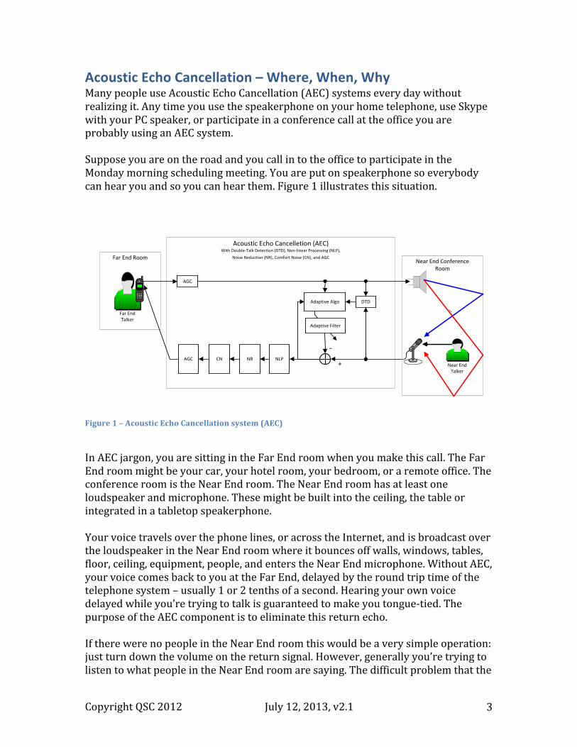
Acoustic Echo Cancellation – Where, When, Why Many people use Acoustic Echo Cancellation (AEC) systems every day without realizing it. Any time you use the speakerphone on your home telephone, use Skype with your PC speaker, or participate in a conference call at the office you are probably using an AEC system. Suppose you are on the road and you call in to the office to participate in the Monday morning scheduling meeting. You are put on speakerphone so everybody can hear you and so you can hear them. Figure 1 illustrates this situation. Figure 1 – Acoustic Echo Cancellation system (AEC)
In AEC jargon, you are sitting in the Far End room when you make this call. The Far End room might be your car, your hotel room, your bedroom, or a remote office. The conference room is the Near End room. The Near End room has at least one loudspeaker and microphone. These might be built into the ceiling, the table or integrated in a tabletop speakerphone. Your voice travels over the phone lines, or across the Internet, and is broadcast over the loudspeaker in the Near End room where it bounces off walls, windows, tables, floor, ceiling, equipment, people, and enters the Near End microphone. Without AEC, your voice comes back to you at the Far End, delayed by the round trip time of the telephone system – usually 1 or 2 tenths of a second. Hearing your own voice delayed while you’re trying to talk is guaranteed to make you tongue-‐tied. The purpose of the AEC component is to eliminate this return echo. If there were no people in the Near End room this would be a very simple operation: just turn down the volume on the return signal. However, generally you’re trying to listen to what people in the Near End room are saying. The difficult problem that the
Copyright QSC 2012 July 12, 2013, v2.1 4
AEC component solves is to turn down the volume of the return echo of your own voice while preserving the sound of the Near End talkers. The Q-‐Sys AEC component includes various sub-‐systems that comprise a complete speech enhancement system. These sub-‐systems include the Adaptive Filter and Adaptive Algorithm that form the core of the AEC component, and additional sub-‐systems including Double-‐Talk Detection (DTD), Non-‐Linear Processing (NLP), Noise Reduction (NR), and Comfort Noise (CN) described in later sections. There are also Automatic Gain Control (AGC) components shown in Figure 1. While separate Q-‐Sys AGC components are often used in conjunction with AEC components, the AGC components are not part of the Q-‐Sys AEC component. The AEC component is part of the communications equipment of the Near End room. However, it exists for the benefit of people calling into the Near End room from the Far End.
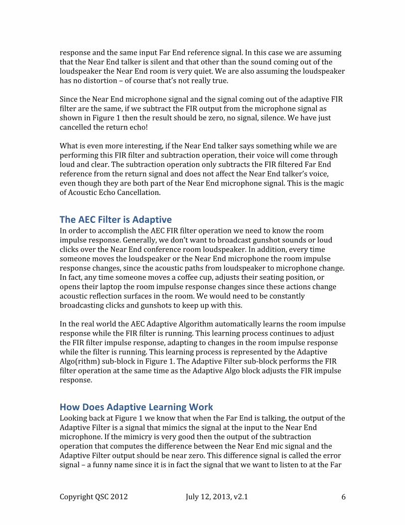
The Room Impulse Response Your voice comes out of the loudspeaker in the Near End room and follows many acoustic paths to arrive at the Near End microphone. There is a direct path from loudspeaker to microphone. There is a path that bounces off the ceiling and arrives at the microphone. There are four different paths that bounce off the four walls. There are paths that bounce off the ceiling, then bounce off one wall, then another wall and finally arrive at the microphone. Each of these paths has a different physical length resulting in different time delays from the loudspeaker to the microphone. As the sound travels through the air and bounces off surfaces it is attenuated and, depending on the surfaces, various frequencies – usually high frequencies – are absorbed. The sound that arrives at the Near End microphone is the combination, or sum, of all these delayed and attenuated copies of the original loudspeaker signal. In Figure 1 two different paths from loudspeaker to microphone are shown in red and blue. In reality hundreds or thousands of different paths combine to form the sound at the microphone. If we broadcast a sharp impulsive sound over the loudspeaker – a loud click or a gunshot sound – and then record the signal arriving at the microphone we obtain a recording that looks like Figure 2.
Copyright QSC 2012 July 12, 2013, v2.1 5
Figure 2 -‐ Room Impulse Response
This recording is referred to as the impulse response of the Near End room. The digital recording in Figure 2 is 0.18 seconds in length and is recorded with a sample rate of 48kHz so that it is 48000 * 0.18 = 8640 samples in length. There is some noise at the beginning of the recording, but the first big spike represents the shortest acoustic path directly from loudspeaker to microphone. The other progressively attenuated spikes represent the different indirect reflected paths. The room impulse reponse completely describes the pattern of acoustic reflections that occurs from loudspeaker to microphone in the Near End room.
The AEC Filter Operation In signal processing jargon, there is a name for the operation of summing different delayed and attenuated copies of a signal. It is called a Finite Impulse Response (FIR) filter. So the Near End room, with all its acoustic reflections, performs an FIR filter operation on the loudspeaker signal to produce the microphone signal. The room impulse response is the impulse response of this FIR filter. An FIR filter operation can also be performed by a Digital Signal Processing (DSP) component, either inside a computer running a DSP program, or using a special purpose DSP circuit. In Figure 1 the block labeled AEC represents such a DSP component. In particular the sub-‐block labeled Adaptive Filter represents the FIR filter. This FIR filter is applied to the incoming Far End telephone signal. This is called the Far End reference signal. If the adaptive FIR filter is loaded with an exact copy of the room impulse response then the output of the adaptive FIR filter will be the same as the input to the microphone since both the Far End room and the AEC Adaptive Filter are performing a FIR filter operation using the same impulse
Copyright QSC 2012 July 12, 2013, v2.1 6
response and the same input Far End reference signal. In this case we are assuming that the Near End talker is silent and that other than the sound coming out of the loudspeaker the Near End room is very quiet. We are also assuming the loudspeaker has no distortion – of course that’s not really true. Since the Near End microphone signal and the signal coming out of the adaptive FIR filter are the same, if we subtract the FIR output from the microphone signal as shown in Figure 1 then the result should be zero, no signal, silence. We have just cancelled the return echo! What is even more interesting, if the Near End talker says something while we are performing this FIR filter and subtraction operation, their voice will come through loud and clear. The subtraction operation only subtracts the FIR filtered Far End reference from the return signal and does not affect the Near End talker’s voice, even though they are both part of the Near End microphone signal. This is the magic of Acoustic Echo Cancellation.
The AEC Filter is Adaptive In order to accomplish the AEC FIR filter operation we need to know the room impulse response. Generally, we don’t want to broadcast gunshot sounds or loud clicks over the Near End conference room loudspeaker. In addition, every time someone moves the loudspeaker or the Near End microphone the room impulse response changes, since the acoustic paths from loudspeaker to microphone change. In fact, any time someone moves a coffee cup, adjusts their seating position, or opens their laptop the room impulse response changes since these actions change acoustic reflection surfaces in the room. We would need to be constantly broadcasting clicks and gunshots to keep up with this. In the real world the AEC Adaptive Algorithm automatically learns the room impulse response while the FIR filter is running. This learning process continues to adjust the FIR filter impulse response, adapting to changes in the room impulse response while the filter is running. This learning process is represented by the Adaptive Algo(rithm) sub-‐block in Figure 1. The Adaptive Filter sub-‐block performs the FIR filter operation at the same time as the Adaptive Algo block adjusts the FIR impulse response.
How Does Adaptive Learning Work Looking back at Figure 1 we know that when the Far End is talking, the output of the Adaptive Filter is a signal that mimics the signal at the input to the Near End microphone. If the mimicry is very good then the output of the subtraction operation that computes the difference between the Near End mic signal and the Adaptive Filter output should be near zero. This difference signal is called the error signal – a funny name since it is in fact the signal that we want to listen to at the Far
Copyright QSC 2012 July 12, 2013, v2.1 7
End. In fact, the Adaptive Algo uses this near zero error signal property to determine how to adjust the impulse response of the Adaptive FIR Filter. It continually monitors the error signal, comparing – or correlating in DSP jargon – the error signal and the Far End reference signal and adjusts the impulse response until these two signals are as uncorrelated as possible, and the error signal is as near zero as possible. When this occurs the filter is said to have “converged” to the room impulse response.
Double Talk Detection (DTD) When only the Far End is talking, the Adaptive Algo can do a pretty good job of correlation and impulse response adjustment. However when the Far End talker is silent, and especially when the Near End is talking, this becomes very difficult. For this reason the adjustment of the Adaptive Filter impulse response is only performed during Far End only speech. This requires the ability to distinguish the Far End only speech condition from the other conditions. In fact, the Adaptive Algo needs to distinguish between four different conditions or “states”:
1. Far End only speech (this is when the FIR impulse response is adjusted) 2. Near End only speech 3. Silence 4. Double Talk -‐ Far End and Near End speaking simultaneously.
Distinguishing between these states is the job of the AEC Double Talk Detector (DTD) shown in Figure 1. Designing a reliable DTD is one of the most complex parts of AEC design.
Multiband AEC The Q-‐Sys AEC component, including FIR filtering and adaptive learning, processes the signal separately in multiple frequency bands. The input signals – the Far End reference signal and the Near End mic signal – are first divided into multiple frequency bands using a bank of bandpass filters. Then the individual frequency band signals are reduced in sample rate (decimated) and a separate adaptive filter and adaptive algorithm is applied to each frequency band. Then the individual frequency bands are again upsampled to the original sample rate and reassembled. Most modern AEC systems work in this way. The configuration is called a “sub-‐band” AEC system. This approach results in faster overall convergence to the room impulse response, and lower CPU computation load.
Residual Echo The Adaptive Filter can do a pretty good job of converging to the room impulse response. But it is never perfect. Generally there is too much Near End room noise, or small movements of objects in the room, speaker or amplifier distortion, and
Copyright QSC 2012 July 12, 2013, v2.1 8
other factors that make it impossible to converge completely to the room impulse response. Often the length of the Adaptive FIR Filter impulse response is not long enough to completely capture the length of the room impulse response. In a real world system the effectiveness of the Adaptive FIR Filter is limited to about 30db of attenuation of the Far End echo. What remains after this attenuation is called “residual echo” and can be annoying.
Non-‐Linear Processing (NLP) To further reduce residual echoes another processing module with the generic name “Non-‐Linear Processor” (NLP) is used as shown in Figure 1. NLP functions like a smart automatic multi-‐band noise-‐gate. The incoming signal, in this case the “error’ signal that contains the desired Near End speech and the undesired Far End residual echoes, is input to the NLP module. There it is divided into multiple frequency bands. In each frequency band a decision is made about whether the band contains primarily desired Near End components or the unwanted Far End residual echoes. If the decision is that the band contains largely residual echoes then the gain for that frequency band is turned down. This Near End vs. Far End decision is a soft or “probabilistic” decision – we’re 80% sure the band is Far End or we’re 20% sure. As a result the gain applied to the band is a smoothly changing gain representing a soft attenuation curve.
Spectral Subtraction The process of attenuating individual frequency bands based on a determination of whether they contain desired or undesired signal components if is often called “spectral subtraction”. While this is a powerful technique, it can introduce undesirable audio artifacts if not used carefully. The artifacts include a kind of churning washing machine sound imposed on the sound or, in the worst case, the infamous “musical noise” artifact where individual frequency bands pop in and out randomly. The Q-‐Sys AEC component goes to great lengths to assure that these spectral subtraction artifacts are inaudible.
Noise Reduction (NR) Another AEC component sub-‐system that follows NLP in the processing chain is Noise Reduction (NR). The purpose of NR is to reduce the level of relatively steady state noises like HVAC fans, lawn mowers, wind, 60 Hz electrical hum. The goal is to reduce these noises without affecting the desired speech. NR is another spectral subtraction sub-‐system similar to NLP. However, rather than basing its frequency band attenuation decision on statistics related to Far End vs. Near End, the NR sub-‐system bases its decision on the steady state nature of signal components. Signals components that maintain a fairly long-‐term steady state
Copyright QSC 2012 July 12, 2013, v2.1 9
power level are attenuated, and components whose power level varies at something like the speech rate are passed through unattenuated. A grey area exists for non-‐speech signals such as musical sounds. We would not like to attenuate the climactic sustained high Bb of an operatic tenor (how anti-‐climatic that would be!). This complicates and adds to the sophistication required in a hi-‐quality NR system such as that used in the Q-‐Sys AEC component. The NR sub-‐system is equipped with a user NR level control that determines how aggressive the NR system is in eliminating steady steady-‐state noise. While the NR and NLP systems have different objectives, in practice there is overlap between the two systems. Adjusting NR level might, in fact, affect the audibility of residual echoes in some cases.
Comfort Noise (CN) Once the signal has passed through the NLP and NR sub-‐systems we generally hear the Near End talker loud and clear and everything else is very quiet – even silent. In fact, when the Near End talker is silent the system might be so quiet that it sounds like the telephone line has been disconnected. For this reason, another AEC sub-‐system called Comfort Noise (CN) is provided as shown in Figure 1. The CN sub-‐system adds an artificial low-‐pass noise signal to the output so that it sounds like there is still a connection when no one is talking. The level of this comfort noise can be adjusted using the CN level control.
Latency As we have seen, the Adaptive Filter, NLP, and NR sub-‐systems are “frequency domain” DSP modules that process the signal in multiple frequency bands. Such processing modules generally have an input to output time-‐delay or “latency” greater than a simple time-‐domain audio processing module such as a parametric EQ. The bank of bandpass filters that divides the signal into separate frequency bands and the subsequent reassembly of the separately processed bands are what cause this latency. The number of frequency bands and the sharpness of the bandpass filters determine the length of the delay. In the case of separate Adaptive Filter, NLP and NR sub-‐systems we might anticipate each module adding separately to the latency, as each module must separate the signal into multiple bands. However, in the Q-‐Sys AEC component the multi-‐band signals are maintained throughout the entire signal path as it passes through Adaptive Filter, NLP, and NR so that only one bandpass filter bank is used.
Copyright QSC 2012 July 12, 2013, v2.1 10
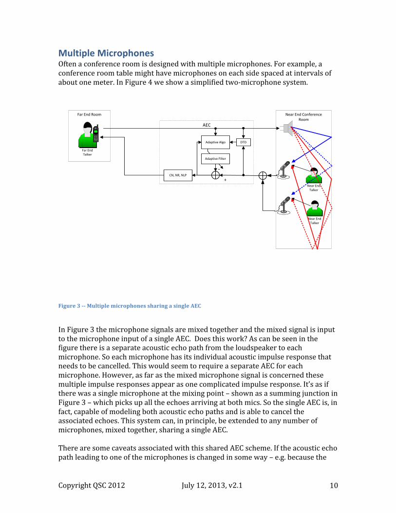
Multiple Microphones Often a conference room is designed with multiple microphones. For example, a conference room table might have microphones on each side spaced at intervals of about one meter. In Figure 4 we show a simplified two-‐microphone system.
Figure 3 -‐-‐ Multiple microphones sharing a single AEC
In Figure 3 the microphone signals are mixed together and the mixed signal is input to the microphone input of a single AEC. Does this work? As can be seen in the figure there is a separate acoustic echo path from the loudspeaker to each microphone. So each microphone has its individual acoustic impulse response that needs to be cancelled. This would seem to require a separate AEC for each microphone. However, as far as the mixed microphone signal is concerned these multiple impulse responses appear as one complicated impulse response. It’s as if there was a single microphone at the mixing point – shown as a summing junction in Figure 3 – which picks up all the echoes arriving at both mics. So the single AEC is, in fact, capable of modeling both acoustic echo paths and is able to cancel the associated echoes. This system can, in principle, be extended to any number of microphones, mixed together, sharing a single AEC. There are some caveats associated with this shared AEC scheme. If the acoustic echo path leading to one of the microphones is changed in some way – e.g. because the
Near End ConferenceRoom
Near End Talker
\
Far End Room
Far End Talker
Adaptive Filter
-
+
Adaptive Algo
AEC
\
Near End Talker
CN, NR, NLP
DTD
Copyright QSC 2012 July 12, 2013, v2.1 11
Near End ConferenceRoom
Near End Talker
\
Far End Room
Far End Talker
Adaptive Filter
-
+
Adaptive Algo
AEC 1
\
Adaptive Filter
-
+
Adaptive Algo
AEC 2
Near End Talker
CN, NR, NLP
CN, NR, NLP
DTD
DTD
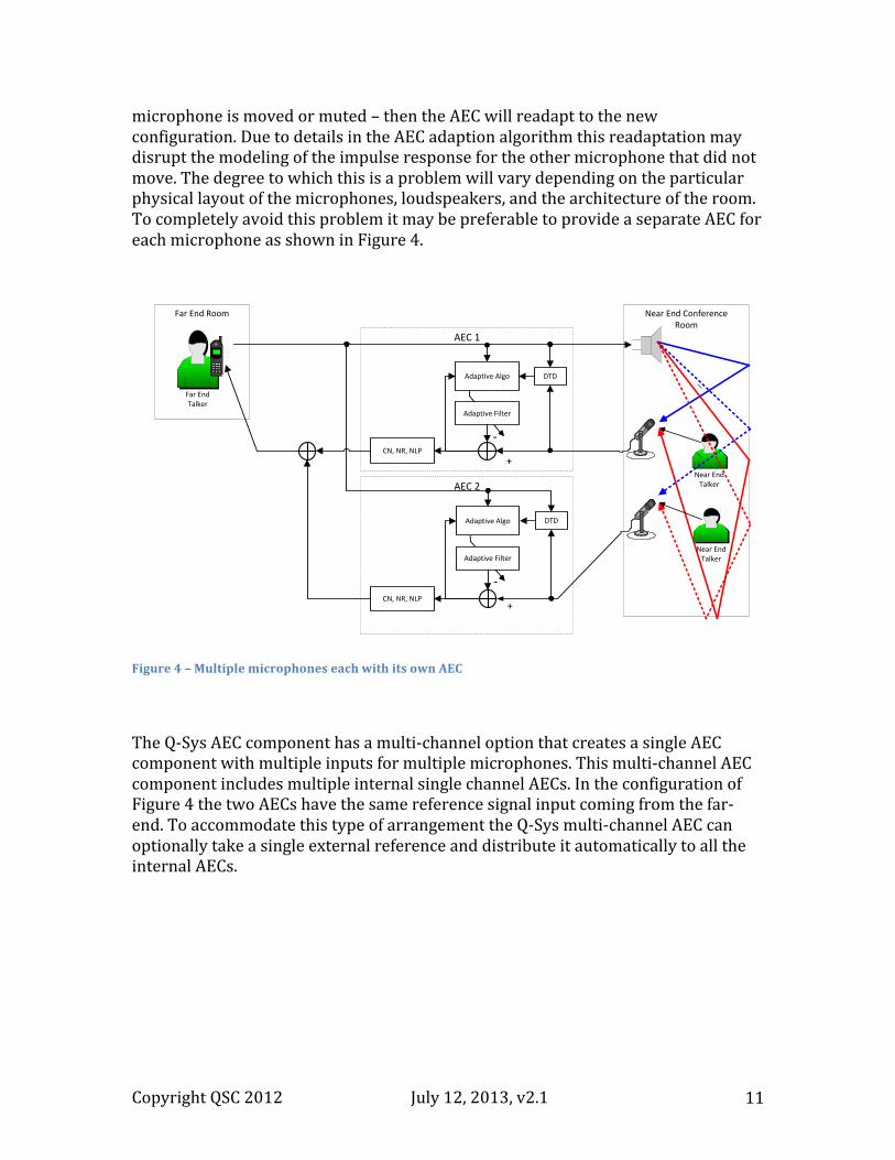
microphone is moved or muted – then the AEC will readapt to the new configuration. Due to details in the AEC adaption algorithm this readaptation may disrupt the modeling of the impulse response for the other microphone that did not move. The degree to which this is a problem will vary depending on the particular physical layout of the microphones, loudspeakers, and the architecture of the room. To completely avoid this problem it may be preferable to provide a separate AEC for each microphone as shown in Figure 4.
Figure 4 – Multiple microphones each with its own AEC
The Q-‐Sys AEC component has a multi-‐channel option that creates a single AEC component with multiple inputs for multiple microphones. This multi-‐channel AEC component includes multiple internal single channel AECs. In the configuration of Figure 4 the two AECs have the same reference signal input coming from the far-‐end. To accommodate this type of arrangement the Q-‐Sys multi-‐channel AEC can optionally take a single external reference and distribute it automatically to all the internal AECs.
Copyright QSC 2012 July 12, 2013, v2.1 12
Push-‐to-‐Talk and Microphone Mute Systems It is common, especially in large configurations, to provide a button on each microphone which functions as a push-‐to-‐talk button or a microphone mute button. In a push-‐to-‐talk system, as the name implies, a near-‐end talker pushes the button when they want to talk. Otherwise the button is off and the mic is muted. When the mic is muted there is no path from the loudspeaker to the microphone input of the AEC, so the AEC is not able to adapt to the room impulse response. When the near-‐end talker pushes the push-‐to-‐talk button and begins speaking, then AEC adaptation will also be disabled because AEC systems are designed, for good reason, to disable adaptation when the near-‐end talker is speaking. The result of this arrangement is that the only time the AEC is able to adapt is in small pauses in the near-‐end talker’s speech while the push-‐to-‐talk button is still pressed, and also while the far-‐end talker is speaking in order to provide a training signal for adaptation. In other words, the AEC is almost never able to adapt in a traditional push-‐to-‐talk system. There is a solution to this problem. Instead of using an analog mute directly on the microphone, which is the traditional case, use a digital push-‐to-‐talk button that is input through Q-‐Sys’s GPIO interface. Use this to mute or unmute the output signal of the AEC by using the GPIO signal to control a gain or mixer component placed on the output of the AEC. In this way the microphones are always active, and AEC training continues whether or not the push-‐to-‐talk button is pressed. Sometimes microphones have a mute button rather than a push-‐to-‐talk button. The function of the button is the same – it turns off the microphone in either case. However, in the case of a mute button, it may be that the intended behavior is that the user will only occasionally push the mute button if he or she wishes to have a side conversation. Otherwise the mute button is not pressed, and the mic is open. If this is the case, then, since the mic is open most of the time, the AEC will be able to adapt and a digital mute signal may not be required.
Copyright QSC 2012 July 12, 2013, v2.1 13
Near End ConferenceRoom
Near End Talker
\
Far End Room
Far End Talker
Adaptive Filter
-
+
Adaptive Algo
AEC
DTD
CN, NR, NLP
\
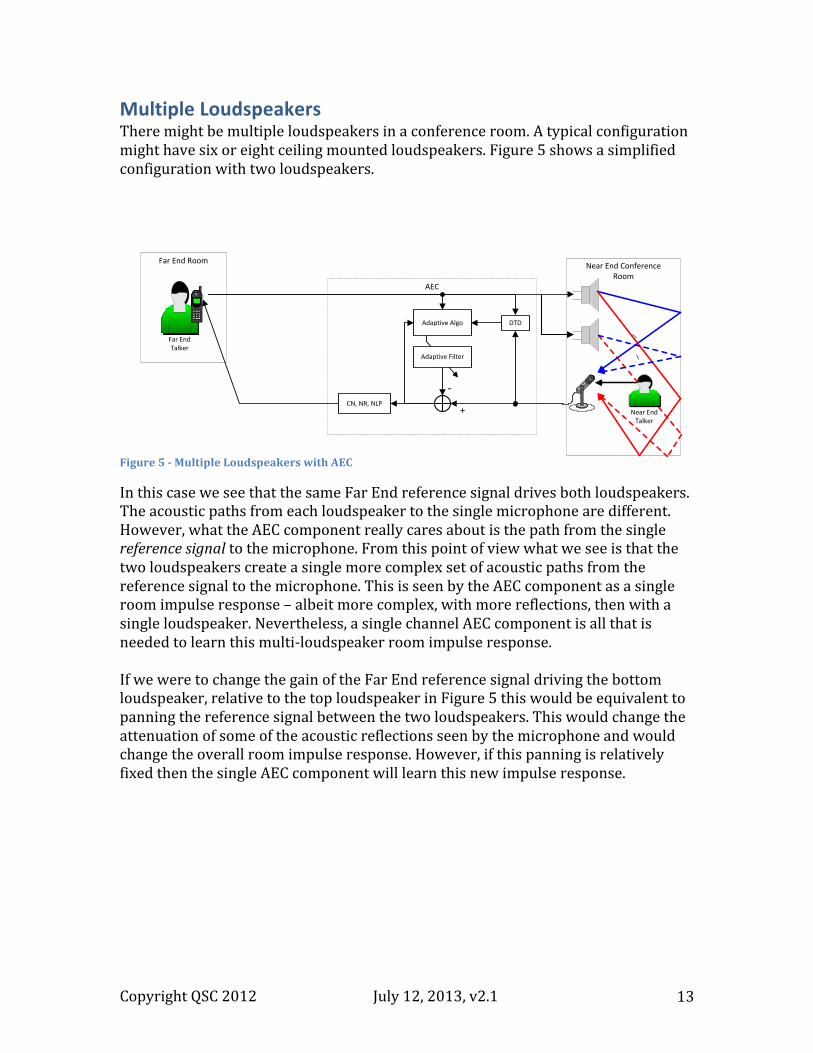
Multiple Loudspeakers There might be multiple loudspeakers in a conference room. A typical configuration might have six or eight ceiling mounted loudspeakers. Figure 5 shows a simplified configuration with two loudspeakers.
Figure 5 -‐ Multiple Loudspeakers with AEC
In this case we see that the same Far End reference signal drives both loudspeakers. The acoustic paths from each loudspeaker to the single microphone are different. However, what the AEC component really cares about is the path from the single reference signal to the microphone. From this point of view what we see is that the two loudspeakers create a single more complex set of acoustic paths from the reference signal to the microphone. This is seen by the AEC component as a single room impulse response – albeit more complex, with more reflections, then with a single loudspeaker. Nevertheless, a single channel AEC component is all that is needed to learn this multi-‐loudspeaker room impulse response. If we were to change the gain of the Far End reference signal driving the bottom loudspeaker, relative to the top loudspeaker in Figure 5 this would be equivalent to panning the reference signal between the two loudspeakers. This would change the attenuation of some of the acoustic reflections seen by the microphone and would change the overall room impulse response. However, if this panning is relatively fixed then the single AEC component will learn this new impulse response.
Copyright QSC 2012 July 12, 2013, v2.1 14
Multiple Loudspeakers, Multiple Microphones and Multiple Far-‐End Callers In the typical conference room we will have multiple loudspeakers and multiple microphones. In addition we might have multiple Far End callers calling in from multiple Far End rooms. Typically, we simply mix the different Far End reference signals together to form a single composite Far End reference. In fact, the telephone company or other conferencing service provider often does this mixing of Far End signals before the composite signal arrives at the conference room. This composite Far End reference is then panned across the various loudspeakers in some desired way. We then place a separate AEC component on each microphone in the Near End room as shown previously. Things become more complicated if we want to mix each Far End caller differently to the various loudspeakers. For example, we might want to pan each far end caller differently across the Near End loudspeakers to give the impression that they are coming from different physical locations. We will discuss this kind of complex configuration in the later “mix-‐minus” section. However, in the typical case where we simply mix the Far End callers together and pan the composite reference across the Near End loudspeakers, we require a single AEC component per Near End microphone. In earlier times, a single channel AEC component was quite expensive. So, it was desirable to share a single AEC component across multiple microphones in a conference room. The microphones were generally controlled by an auto-‐mixer. Whenever anyone seated in front of a particular microphone would begin to speak, that microphone gain would automatically increase. What the AEC component sees is a changing room impulse response depending on who is talking. So, each time a new Near End talker begins, the AEC adaptive filter readapts. This readaptation takes time so there are occasional audible echoes as different Near End talkers take turns. With the Q-‐Sys system there is sufficient signal processing power to allow for a separate AEC component per microphone so that this compromise is not necessary.
Copyright QSC 2012 July 12, 2013, v2.1 15
Conference Room 2
Near End Talker
\
Adaptive Filter
-
+
Adaptive Algo
AEC 2
DTD
CN, NR, NLP
Conference Room 1
Near End Talker
\
Adaptive Filter
-
+
Adaptive Algo
AEC 1
DTD
NLP, NR, CN
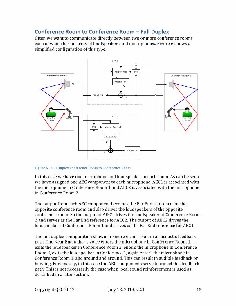
Conference Room to Conference Room – Full Duplex Often we want to communicate directly between two or more conference rooms each of which has an array of loudspeakers and microphones. Figure 6 shows a simplified configuration of this type. Figure 6 -‐ Full Duplex Conference Room to Conference Room
In this case we have one microphone and loudspeaker in each room. As can be seen we have assigned one AEC component to each microphone. AEC1 is associated with the microphone in Conference Room 1 and AEC2 is associated with the microphone in Conference Room 2. The output from each AEC component becomes the Far End reference for the opposite conference room and also drives the loudspeakers of the opposite conference room. So the output of AEC1 drives the loudspeaker of Conference Room 2 and serves as the Far End reference for AEC2. The output of AEC2 drives the loudspeaker of Conference Room 1 and serves as the Far End reference for AEC1. The full duplex configuration shown in Figure 6 can result in an acoustic feedback path. The Near End talker’s voice enters the microphone in Conference Room 1, exits the loudspeaker in Conference Room 2, enters the microphone in Conference Room 2, exits the loudspeaker in Conference 1, again enters the microphone in Conference Room 1, and around and around. This can result in audible feedback or howling. Fortunately, in this case the AEC components serve to cancel this feedback path. This is not necessarily the case when local sound reinforcement is used as described in a later section.
Copyright QSC 2012 July 12, 2013, v2.1 16
Near End ConferenceRoom
Near End Talker
\
Far End Room
Far End Talker
Acoustic Echo Cancelletion (AEC)With Sound Reinforcement output (SR), Feeback Cancellation (FB),
Double-Talk Detection (DTD), Non-linear Processing (NLP),
Noise Reduction (NR), Comfort Noise (CN), and AGC
Adaptive Filter
-
+
Adaptive Algo DTD
NLPNRCNAGC
AGC
In a full-‐duplex configuration all of the multi-‐microphone, multi-‐loudspeaker considerations apply. In short, in the typical case one AEC component is associated with each microphone in each conference room.
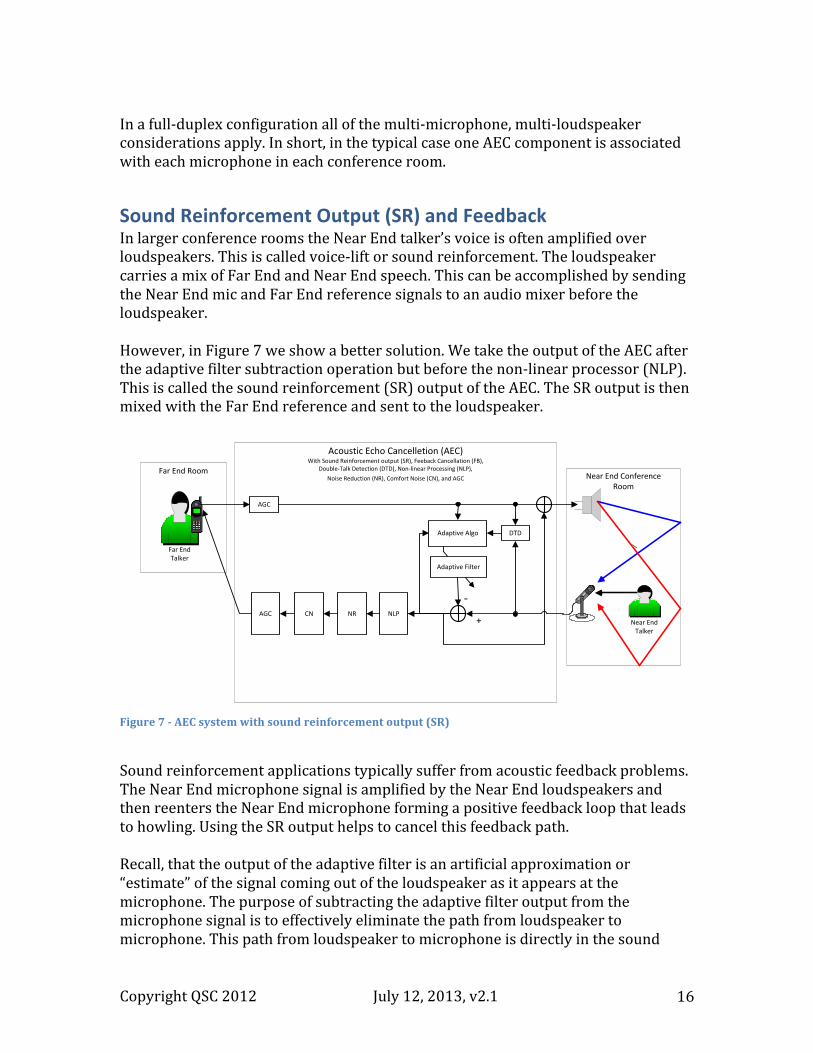
Sound Reinforcement Output (SR) and Feedback In larger conference rooms the Near End talker’s voice is often amplified over loudspeakers. This is called voice-‐lift or sound reinforcement. The loudspeaker carries a mix of Far End and Near End speech. This can be accomplished by sending the Near End mic and Far End reference signals to an audio mixer before the loudspeaker. However, in Figure 7 we show a better solution. We take the output of the AEC after the adaptive filter subtraction operation but before the non-‐linear processor (NLP). This is called the sound reinforcement (SR) output of the AEC. The SR output is then mixed with the Far End reference and sent to the loudspeaker. Figure 7 -‐ AEC system with sound reinforcement output (SR)
Sound reinforcement applications typically suffer from acoustic feedback problems. The Near End microphone signal is amplified by the Near End loudspeakers and then reenters the Near End microphone forming a positive feedback loop that leads to howling. Using the SR output helps to cancel this feedback path. Recall, that the output of the adaptive filter is an artificial approximation or “estimate” of the signal coming out of the loudspeaker as it appears at the microphone. The purpose of subtracting the adaptive filter output from the microphone signal is to effectively eliminate the path from loudspeaker to microphone. This path from loudspeaker to microphone is directly in the sound
Copyright QSC 2012 July 12, 2013, v2.1 17
reinforcement feedback loop. So when we eliminate it as part or the AEC operation we also eliminate it as a source of feedback in the Near End room. This is the advantage of using the SR output for sound reinforcement. Even if the system gain is such that howling does not occur, the introduction of an amplification path directly from the near-‐end microphone to the near-‐end loudspeakers can result in a coloration of both the near-‐end and far-‐end signals. This is because they are allowed to recirculate through the system repeatedly entering the microphone and exiting the loudspeaker causing a kind of reverberation effect. The use of the SR output can reduce this reverberation effect because it attempts to stop the loudspeaker signal from reentering the microphone. The advantage of taking the SR output before the NLP module is that there are no artifacts from the spectral subtraction used in NLP and NR. The SR output does contain residual echoes. However, since the entire Far End signal is broadcast over the Near End loudspeakers, the addition of Far End residual echoes is not a significant problem. The Q-‐Sys AEC provides the SR output on each AEC channel. Many AEC systems do not provide a separate SR output. The method of adaptive filter feedback cancellation associated with the SR output is sometimes imperfect. In practice it might be accompanied by an additional feedback cancellation component not shown in Figure 7. This additional FB component might rely on adaptive notch filtering to additionally suppress feedback. There is one disadvantage to using the SR output as opposed to connecting the local microphone directly through amplification to the local speaker when sound reinforcement is desired. The SR output of the AEC component has the same latency as the AEC component itself. This latency is 13.3 milliseconds for an AEC filter length of 512 samples. When other system and component latency is added to this, the total delay from microphone to loudspeaker can be as much as 20 milliseconds. This can be excessive in some live sound situations. In these cases it may be preferable to use the direct connection from microphone to loudspeaker rather than use the AEC SR output. Most commercial systems do not provide a separate SR output from the AEC. Q-‐Sys gives the designer the choice of whether to use the direct mic signal or the SR output for local sound reinforcement.
Copyright QSC 2012 July 12, 2013, v2.1 18
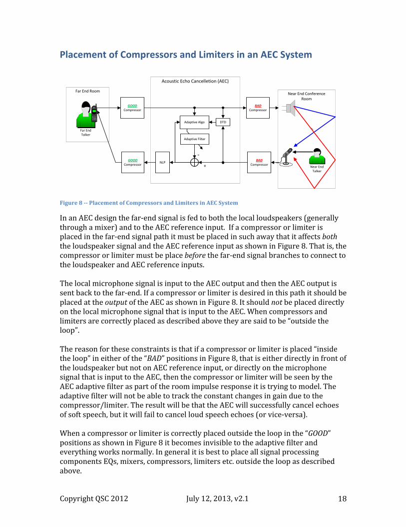
Placement of Compressors and Limiters in an AEC System
Figure 8 -‐-‐ Placement of Compressors and Limiters in AEC System
In an AEC design the far-‐end signal is fed to both the local loudspeakers (generally through a mixer) and to the AEC reference input. If a compressor or limiter is placed in the far-‐end signal path it must be placed in such away that it affects both the loudspeaker signal and the AEC reference input as shown in Figure 8. That is, the compressor or limiter must be place before the far-‐end signal branches to connect to the loudspeaker and AEC reference inputs. The local microphone signal is input to the AEC output and then the AEC output is sent back to the far-‐end. If a compressor or limiter is desired in this path it should be placed at the output of the AEC as shown in Figure 8. It should not be placed directly on the local microphone signal that is input to the AEC. When compressors and limiters are correctly placed as described above they are said to be “outside the loop”. The reason for these constraints is that if a compressor or limiter is placed “inside the loop” in either of the “BAD” positions in Figure 8, that is either directly in front of the loudspeaker but not on AEC reference input, or directly on the microphone signal that is input to the AEC, then the compressor or limiter will be seen by the AEC adaptive filter as part of the room impulse response it is trying to model. The adaptive filter will not be able to track the constant changes in gain due to the compressor/limiter. The result will be that the AEC will successfully cancel echoes of soft speech, but it will fail to cancel loud speech echoes (or vice-‐versa). When a compressor or limiter is correctly placed outside the loop in the “GOOD” positions as shown in Figure 8 it becomes invisible to the adaptive filter and everything works normally. In general it is best to place all signal processing components EQs, mixers, compressors, limiters etc. outside the loop as described above.
Near End ConferenceRoom
Near End Talker
\
Far End Room
Far End Talker
Acoustic Echo Cancelletion (AEC)
Adaptive Filter
-
+
Adaptive Algo DTD
NLPGOOD
Compressor
GOODCompressor
BADCompressor
BADCompressor
Copyright QSC 2012 July 12, 2013, v2.1 19
Mix-‐Minus Room Configurations In a large sound reinforcement setting, for example in a Senate or Parliamentary chamber, we might have many loudspeakers positioned around the room and many microphones. There might be one loudspeaker and one microphone for each member of Parliament. In such a setting it is common to use a “mix-‐minus” configuration. With mix-‐minus each member hears every member of the Parliament over their loudspeaker except themselves. This helps to avoid acoustic feedback and howling. Even with mix-‐minus there is still the potential of acoustic feedback in these configurations. Though Member X’s voice is excluded from the mix going to Member X’s loudspeaker, there is still a potential acoustical feedback path going from every other loudspeaker to Member X’s microphone. In addition there is the possibility that Member X’s voice will exit Member Y’s loudspeaker, enter Member Y's microphone and from there to Member X's loudspeaker and back into Member X’s microphone. AEC can be used to help cut these feedback paths. An AEC is associated with Member X’s microphone. This AEC will learn the composite room impulse response from every loudspeaker in the room to Member X’s microphone and will cancel it. The Far End reference signal sent to Member X’s AEC is the mix-‐minus signal that is the sum of every output of every microphone in the room except Member X’s microphone. If Member X’s microphone signal was also included in the reference signal for Member X’s AEC, then the AEC would also try to cancel Member X’s voice – not a good idea. In total there is an AEC associated with each microphone in the mix-‐minus configuration. Each AEC uses as Far End reference signal the mix-‐minus signal that drives its loudspeaker. The Q-‐Sys AEC component can be configured for multiple channels. In multi-‐channel use an additional property selects whether to use a single common reference signal for all AEC channels or separate reference signals for each channel. In the mix-‐minus configuration separate reference signals are required. There are a number of situations where this type of mix-‐minus configuration can be used. These include extended conference rooms with different zones of loudspeakers, and dais configurations where there is a long table onstage with several microphones and loudspeakers.
AEC in the Q-‐Sys System Q-‐Sys AEC is implemented as a general-‐purpose, 1 to n-‐channel, virtual signal processing component that can be connected anywhere in a Q-‐Sys design. This puts Q-‐Sys AEC in a class by itself. In other systems, AEC is provided as a fixed option on an audio I/O card. Typically this will take the form of a program running on a dedicated DSP processor on the
Copyright QSC 2012 July 12, 2013, v2.1 20
card. By contrast, multiple instances of the Q-‐Sys AEC component can be created and they all run on an Intel processor in the Q-‐Sys Core. An advantage of the Q-‐Sys approach is that any system inputs and outputs can be connected to the Q-‐Sys AEC components. For example, audio I/O may come from any mix of CobraNet, AES3, Q-‐LAN, telephone hybrid interfaces, outputs from VOIP soft phones, or I/O from the latest Q-‐Sys I/O box such as the newly announced IO-‐22. These can all be wired to different Q-‐Sys AEC components. In addition, any kind of EQ, delay, indeed any network of Q-‐Sys design components can be connected to the Q-‐Sys AEC inputs and outputs. This not only makes the Q-‐Sys AEC components more useful today, but also helps to protect investment as new I/O devices and new software revisions are integrated into existing systems.
AEC Specifications Most AEC systems, including the Q-‐Sys AEC, list the following specifications:
• Bandwidth – the overall audio bandwidth from input to output. • Latency – the delay of the audio signal from input to output. • Tail length – the maximum room impulse response that can be modeled by
the adaptive filter. • Convergence Rate – the rate at which the AEC system converges to the
maximum echo attenuation. • Total Cancellation – the attenuation of the echo signal once the AEC system
has converged. An examination of the Q-‐Sys AEC spec sheet shows that its numbers are quite competitive with other state of the art AEC systems. However, these five numbers do not adequately reflect the quality of an AEC system. The problems that affect real-‐world AEC systems, and that distinguish a good AEC system from a bad one, are more likely related to dynamic behavior. Does the AEC have audio dropouts during brief double-‐talk interruptions? Is there audible burbling or musical noise due spectral subtraction? Are there dropouts in speech after periods of silence? Is the quality of background noise smooth and consistent or is there audible noise modulation? In this section we discuss each of the baseline five numbers listed above and how they relate to real-‐world AEC performance. We also discuss a more interesting set of numbers defined by the ITU G.167 AEC standard that do reflect some of the dynamic behavior issues confronted by real-‐world AEC systems. In the next section we discuss practical methods for evaluating the quality of an AEC system.
Copyright QSC 2012 July 12, 2013, v2.1 21
Bandwidth The Q-‐Sys AEC is an Ultra-‐Wideband hi-‐fidelity AEC with 20 Hz to 22 kHz full audio bandwidth. In the AEC literature and standards the default bandwidth is telephone bandwidth 300 Hz -‐ 4kHz. Later AEC standards refer to “Wideband” AEC systems with a 100 Hz -‐ 8kHz bandwidth. AEC systems with bandwidth greater than 20kHz are a fairly recent phenomenon and the term Ultra-‐Wideband is used for these.
Latency Recall that most modern AEC systems, including Q-‐Sys AEC, process the signal in many narrow frequency bands. This introduces a delay in the signal. The Q-‐Sys delay is 21 milliseconds. This is typical for this type of system. The delay is well below the delay introduced by telephone systems and especially VOIP system where delay can be greater than 200 milliseconds. In sound reinforcement, typically used in larger rooms, this 21 millisecond delay is acceptable. Longer delays greater than 30 milliseconds begin to interfere with normal speaking patterns.
Tail Length A large room can have a room impulse response greater than 2 seconds. This is typically measured as the RT60 reverberation time: the time it takes for the impulse response to decay 60db from its initial level (RT60). However, the AEC tail length – the length of the adaptive filter – is never this long. A long AEC tail length is usually around 200 milliseconds. This is the default tail length of the Q-‐Sys AEC filter. One might think that the longer the AEC tail length the better. However, this is not true. After about 200 milliseconds it becomes difficult for the adaptive filter to model the impulse response in a real room due to limitations of acoustic noise, small movements in the room, etc. In addition, the longer the tail length the slower the AEC filter adapts. Therefore, in practical systems there is generally little or no benefit to AEC tail-‐lengths beyond about 200 milliseconds and the system performance begins to degrade with longer tail-‐lengths. The longer the tail-‐length the more computation the filter requires. However, even if one is prepared to dedicate enormous compute resources to the AEC adaptive filter, longer tail lengths still do not provide better performance.
Convergence Rate This is the most misleading AEC spec of all. Notice above that we described the convergence rate as “the rate at which the AEC system converges to the maximum echo attenuation”. We did not however say that this is the rate at which the AEC adaptive filter converges. This is because the convergence rate that listed on AEC spec sheets is generally the convergence rate of the non-‐linear processor NLP, not the convergence rate of the adaptive filter. The NLP “converges” very rapidly, in a fraction of a second, immediately cutting down the perceived echo. In the
Copyright QSC 2012 July 12, 2013, v2.1 22
background the adaptive filter that models the room impulse response converges much more slowly, taking as long as 8-‐10 seconds to fully converge. This slow convergence of the adaptive filter is, in fact, a good thing. A very fast filter convergence rate also implies a fast divergence rate. The result is that, if the filter convergence is too fast, then when double-‐talk occurs because the Near End talker interrupts the Far End talker, the filter rapidly diverges causing ongoing unwanted echo and readaptation. A fast NLP system and a moderate adaptive filter is a better choice. How fast is the NLP “convergence”? In a well-‐designed AEC the number varies according to the different states – double talk, far-‐end only, near-‐end only, silence. Therefore to quote a specific convergence rate for the NLP is inherently misleading. But this is, in fact, the convergence rate that is generally given for AEC systems – including Q-‐Sys AEC. We will discuss better ways to evaluate AEC systems below.
Total Cancellation This specification is closely related to what the AEC literature refers to as Echo Return Loss Enhancement (ERLE). This measures how much, in dB, the Far End echo arriving at the Near End microphone is attenuated by the AEC system once the AEC has converged. This value, as given in AEC specs, includes both the attenuation due to the adaptive filter and the NLP system. Of course, if the double-‐talk detection system (DTD) is working well, it is easy to attenuate the echo almost completely during Far End only speech – just turn down the return signal. During double-‐talk it is much more difficult to achieve a high total cancellation or ERLE. But the value that is given in AEC specs is typically the total cancellation during Far End only speech. Generally echo attenuation greater than about 40db is as good as silence. A more interesting specification is the ERLE before NLP is applied. This shows how well the adaptive filter alone is performing, and indicates how much additional work the NLP has to do, and is an indication of how well the system might perform in double-‐talk, assuming no divergence occurs. This value might be about 30db for a good filter.
ITU G.167 AEC Standard ITU G.167 is a published standard for AEC systems. This document describes a series of tests and measurements that are performed on an AEC system and lists minimum acceptable performance levels for these tests. The Q-‐Sys AEC meets or exceeds all of the G.167 performance criteria. The results of G.167 compliance testing for the Q-‐Sys AEC are provided in a separate document. The G.167 tests are more comprehensive and reflect more of the real-‐world behavior of an AEC system when compared with the 5 numbers described above. In particular G.167 includes tests that reflect dynamic behavior due to double-‐talk
Copyright QSC 2012 July 12, 2013, v2.1 23
interruptions, recovery after double-‐talk, etc. However, G.167 does not test for background noise modulation, or spectral subtraction artifacts during double-‐talk. A better method for comparing AEC systems would include a number of standardized sound files that reflect different conversation scenarios and noise conditions. Each AEC system would process the same sound files and the results would be provided for comparison. The industry has not evolved to this point yet.
Evaluating a Real-‐World AEC System In this section we describe a number of informal tests that anyone can perform on an AEC system to assess its quality. The test evaluator is the Far End caller. The Far End caller calls into the Near End room. There is an assistant, the Near End talker, sitting in the Near End room. In the case where the Far End caller is calling over a low latency network it is better to introduce a 100 – 200 millisecond delay in the Far End path so that the Far End caller can more easily hear the echo artifacts. All of the evaluation of AEC quality is done by the Far End caller while listening to the return signal from the Near End room. Artifacts might affect the Near End speech as heard by the Far End caller, the return echoes of the Far End caller, and the background noise from the Near End room as heard by the Far End caller.
Initial Convergence Restart the AEC system. The Far End caller begins to talk in a steady uninterrupted manner. How long does it take the return echoes to disappear? This should be in the range of 1-‐2 seconds. The Far End talker should continue to talk for about 10 seconds to assure that the adaptive filter has fully converged.
Near-‐End Dropouts Due to Far End Interruptions After the system has fully converged, the Near End talker should begin to talk in a steady uninterrupted manner. The Far End talker makes occasional short interjections while the Near End talker continues: “Yes”, “Un-‐huh”, “Oh”. During and shortly after each interjection does the Near End talker’s voice drop out? There should be little or no audible dropouts.
Dropouts During State Transitions After the system has converged both talkers remain silent for about 10 seconds. Then the Far End talker starts. Is there any audible echo at the start of the Far End speech? There should be none. After both speakers are silent for a period of 10 seconds, the Near End talker begins to speak. Is the beginning of the Near End talker’s speech clipped or cut-‐off? After the system has converged. The Far End caller begins to talk in a steady uninterrupted manner. The Near End talker makes occasional interruptions -‐ short phrases like “How are you?” “What is your astrological sign?” – while the Far End
Copyright QSC 2012 July 12, 2013, v2.1 24
talker continues. The beginning of the syllable of the Near End talker should not be cut off. After the Near End talker stops the return signal should immediately go silent with little or no trailing Far End echoes.
Tracking Behavior After the system has converged the Far End talker begins to talk in a steady uninterrupted manner. The Near End talker moves the Near End microphone around for several seconds. The Far End caller should here some echo during this movement but it should be at a fairly low level. After the Near End talker stops moving the microphone the echoes should disappear quickly, after about 1 second.
Spectral Distortion and Divergence During Double Talk After the system has converged, both the Far End and Near End talker begin to talk in a steady uninterrupted manner. The Far End talker should continue to hear the Near End talker reasonably well. There will probably be some audible distortion of the Near End voice and some occasional audible Far End echoes. However, these distortions and echoes should not be excessive and the Near End speech should remain intelligible. There might be some burbling of the Near End speech but this also should not be excessive.
Background Noise Modulation Turn on a fan or other noise generator in the Near End room. Let the system converge. Adjust the Noise Reduction to reduce the level of the fan noise that the Far End talker hears. The quality of the noise should be stable with little or no spectral subtraction artifacts. Adjust Comfort Noise to a reasonable level. When the Far End talker starts talking there should not be a noticeable surge in the level or character of the background noise. When the Near End talker begins talking there should also be a continued smooth level of background noise with no noticeable change in level or character.
Adaptation During Double Talk Restart the AEC system. Immediately both the Far End and Near End talker begin to talk in a steady uninterrupted manner. The level of the Far End echoes should gradually decrease. This implies that the system is able to converge during double-‐talk. This is a desirable feature of some advanced AEC system, including Q-‐Sys AEC.
Conclusion We have presented the basic principles of Q-‐Sys AEC design with a particular emphasis on the kinds of configurations that audio designers confront in the real world. Our goal has been to make this highly specialized information – multi-‐loudspeaker multi-‐microphone AEC designs, the story behind AEC specifications, how to evaluate AEC systems, etc. – accessible to a wider range of audio system designers. We believe the flexibility of Q-‐Sys AEC components and the Q-‐Sys system, together with an increased understanding in the audio community of the problems
Copyright QSC 2012 July 12, 2013, v2.1 25
of AEC integration, will help to enable the next generation of high performance networked audio designs.
Best Practices for AEC Usage 1. Adjust gain of AEC reference input so that it is at approximately the same
level as the AEC microphone input. Use a gain or mixer unit to adjust the AEC reference gain if necessary to maintain this balance. “Approximately the same level” means within about +-‐6dB.
2. Place signal processing modules, especially compressors and limiters, “outside the loop”, as described in the section “Placement of Compressors and Limiters in an AEC System” of this document and as shown in Figure 8.
3. Use the AEC’s SR output for local sound reinforcement in situations where the sound-‐reinforcement can tolerate a 20 milliseconds delay. Otherwise use the local microphone signals directly for sound reinforcement.
4. For rooms with multiple microphones, use a multi-‐channel AEC component with one channel per microphone and use a shared reference signal.