Q Light Controller Plus Documentation - qlcplus.org_manual_4.11.0.pdf · Q Light Controller Plus...
168
Q Light Controller Plus User Documentation Updated to version 4.11.0 June, 24th 2017 Page 1
Transcript of Q Light Controller Plus Documentation - qlcplus.org_manual_4.11.0.pdf · Q Light Controller Plus...
Q Light Controller Plus
User Documentation
Updated to version 4.11.0June, 24th 2017
Page 1

BasicsBasic Concepts & GlossaryQuestions & Answers
AdvancedCommand-Line ParametersManual parameters tuningGUI style customizationKiosk modeWeb Interface
Main Window
DMX Monitor
DMX Address tool
DMX Dump
Live Edit
Fixture Manager
Add/Edit FixturesFixture Group EditorChannels Groups Editor
Fixtures remapping
How to add fixtures
Function Manager
Scene Editor
Chaser Editor
Show Editor
EFX Editor
Collection Editor
RGB Matrix Editor
RGB Script API Script Editor
Audio Editor
Video Editor
Page 2

Function Wizard
Select FunctionsSelect Fixtures
Show Manager
Virtual Console
ButtonButton MatrixAdd Button MatrixSliderSlider MatrixAnimationSpeed DialXY PadCue ListFrameSolo FrameLabelAudio triggersSelect Input ChannelWidget Styling & Placement
Simple Desk
Input/Output
Input/Output mappingInput profilesAudio Input/OutputSupported input devices
Plugins:ArtNetDMX USBE1.31 (sACN)Enttec WingHIDLoopbackMIDIOLAOSCPeperoniuDMXVelleman
Fixture Definition Editor
Capability EditorCapability WizardChannel Editor
Page 3
Fixture EditorMode EditorHead Editor
TutorialsScene tutorialMultipage frame tutorialSound control tutorialBCF2000 + LC2412 tutorial
Page 4

Basic Concepts & GlossaryQ Light Controller Plus (QLC+ for short) is meant to control lighting equipment used in variousperformances, like live concerts and theatres etc. The main intention is that QLC+ will be able tooutperform commercial lighting desks without the need for a 500+ page manual through the useof an intuitive and flexible user interface.
This page has been arranged in alphabetical order to facilitate searching for a specific topic.
Audio
An audio function is an object representing an audio file stored in a disk.QLC+ supports the most common audio formats like Wave, MP3, M4A, Ogg and Flac. It supportsmono or stereo channels and several sample rates like 44.1KHz, 48KHz, etc...Audio functions can be placed in Chaser or in a Show at the desired time, using the ShowManager panel.Like most of the QLC+ functions, Audio supports fade in and fade out times.
Blackout
Blackout is used to set all channels in all universes to zero and keep them that way, regardless ofwhich functions are currently being run or what values have been set to them manually. Whenblackout is turned off, the current values of all channels are sent to each universe.
Capabilities
Some channels in intelligent fixtures provide many kinds of functions, or capabilities likeswitching the lamp on when the channel value is [240-255], setting a red color on a color wheelwhen the value is exactly [15], or simply controlling the fixture's dimmer intensity with values [0-255]. Each of these individual function is called a capability and each of them has these threeproperties:
Minimum value: The minimum channel value that provides a capability.Maximum value: The maximum channel value that provides a capability.Name: The friendly name of a capability.
Channel Groups
Channel groups can be added and defined in the Fixture Manager panel by using the Channelgroups editor.Channel groups can have a user defined name and can group together any user definedchannels selected from an existing Fixtures list.
Chaser
A chaser function is built up from multiple scenes that are run in sequence, one after the other,when the chaser function is started. The next function is run only after the previous has finished.Any number of functions can be inserted to a chaser.
The Chaser function's direction can be reversed. The Chaser function can also be set to do aninfinite loop, an infinite ping-pong-loop (direction is reversed after each pass) or it can runthrough just once, in a single-shot mode, after which it terminates by itself. If the function is set to
Page 5

loop infinitely, it must be stopped manually.
As of version 3.3.0, each chaser has its own speed settings:
Fade In: The fade in speed of a stepHold: The hold time of a stepFade Out: The fade out speed of a stepDuration: The duration of a step
Copies of chaser functions can be created with the Function Manager. The scenes inside achaser are not duplicated when a chaser is copied. Only the order and direction are copied to thenew one.
Click And Go
Click And Go is a technology that allows the user to quickly access macros and colors in acompletely visual way and with just a couple of clicks. This can lead to more efficient live showsand more freedom to choose the desired result very easily.So far, three types of widgets are available:
Single Color (applies to: Red, Green, Blue, Cyan, Yellow, Magenta, Amber and Whiteintensity channels)RGB Color Picker. Controls values for selected RGB channels with a single clickGobo/Macro Picker. Access and display a Gobo/Macro defined in the Fixture definition
An overview with screenshots is available here
Collection
A collection function encapsulates multiple functions that are run simultaneously when thecollection function is executed. Any number of functions can be inserted to a collection, but eachfunction can be inserted only once and a collection cannot be a direct member of itself.
Collections have no speed settings. The speed of each member function is set individually usingtheir own editors.
Copies of collection functions can be created with the Function Manager. The functionscontained in a collection are not duplicated; only the list of functions is copied.
DMX
DMX is short for Digital MultipleX. It basically defines a whole bunch of properties, protocol,wiring etc. In the case of lighting software, it defines the maximum number of channels (512) peruniverse and the value range of each channel (0-255).
QLC+ supports 4 individual universes. They do not necessarily need to be connected to DMXhardware; rather, DMX has just been selected as the de facto lighting standard. Actual hardwareabstraction (whether it's analogue 0-10V, DMX or some other method) is achieved through outputplugins.
EFX
An EFX function is mainly used to automate moving lights (e.g. scanners & moving heads). TheEFX can create complex mathematical paths on an X-Y plane that are converted to DMX valuesfor the fixture's pan and tilt channels. Only fixtures that contain valid pan & tilt channels can
Page 6
take part in an EFX function. Lately EFX can control also other channels like Dimmer or RGB.
Fixtures
A fixture is essentially one lighting device. It can be, for example, one moving head, one scanner,one laser etc.. However, for simplicity, individual PAR cans (and the like) that are usuallycontrolled thru one dimmer channel per can, can be grouped together to form one single fixture.
With the Fixture Definition Editor, users can edit shared fixture information stored in a fixturelibrary that contains the following properties for each fixture:
Manufacturer (e.g. Martin)Model (e.g. MAC250)Type (Color Changer, Scanner, Moving Head, Smoke, Haze, Fan...)Physical properties (bulb type, beam angle, dimensions...)Channels:
Channel group (Intensity, Pan, Tilt, Gobo, Color, Speed etc.)8bit and 16bit channel bindings for pan & tilt groupsOptional primary color for intensity channels (RGB/CMY)Value ranges for channel features (e.g. 0-5:Lamp on, 6-15:Strobe etc..)
These fixture definitions can then be used to create actual fixtures in the Q Light Controller Plusapplication, that will have additional properties defined by users:
DMX UniverseDMX AddressName
Several instances of a fixture can be created (e.g. users must be able to have several instancesof a MAC250 in use). Each fixture can be named, but the name is not used internally by QLC+ toidentify individual fixture instances. The same goes for the DMX address. Nevertheless users areencouraged to name their fixtures in some systematic way to help identify each of them -- ifnecessary.
Generic dimmer devices don't need their own fixture definitions, because usually multipledimmers are patched into a common address space, employing one or more dimmer racks.Users can create instances of these generic dimmer entities just by defining the number ofchannels each one of them should have.
Fixture Group
A fixture group is, as the name says, a group of fixtures. They also define (at a rather basic level)the actual physical, real world arrangement of these fixtures. This knowledge can be used, forexample, in the RGB Matrix to produce a wall of RGB-mixable lights that can act as individualpixels in a graphic pattern or scrolling text.
Fixture Mode
Many manufacturers design their intelligent lights in such a way that they can be configured tounderstand different sets of channels. For example, a scanner might have two configurationoptions: one for only 8bit movement channels (1x pan, 1x tilt) and another one for 16bitmovement channels (2x pan, 2x tilt). Instead of creating a completely new fixture definition foreach variation, they have been bundled together in QLC+'s fixture definitions into fixture modes.
Page 7
Functions
The number of functions is practically unlimited. Functions are used to automate the setting ofvalues to DMX channels. Each function type has its own way of automating lights.
The function types are:
SceneChaserSequenceEFXRGB MatrixCollectionShowAudio
Each function can be named and, although the name is not used to uniquely identify individualfunctions, users are encouraged to name their functions in some systematic and concise way tohelp identify each of them. For your own comfort.
As of version 3.3.0, each function has its own speed settings:
Fade In: The time used to fade HTP (in Scenes also LTP) channels to their target valueFade Out: The time used to fade HTP/intensity channels back to zeroDuration: The duration of the current step (not applicable on Scenes)
Grand Master
The Grand Master is used as the final master slider before values are written to the actualphysical DMX hardware. Usually, the Grand Master affects only Intensity channels, but can alsobe changed to effect the values of all channels.
The Grand Master has also two Value Modes that control the way how the Grand Master affectschannel values:
Reduce: Affected channels' values are reduced by a percentage set with the Grand Masterslider. For example, Grand Master at 50% will result in all affected channels being reducedto 50% of their current values.Limit: Affected channels cannot get larger values than the value set with the Grand Masterslider. For example, Grand Master at 127 will result in all the affected channels' maximumvalues being limited at exactly 127.
Head
A head represents an individual light output device in a fixture. Usually, a single fixture containsexactly one output, like the lens, the bulb, or a set of LEDs. There is, however, an increasingnumber of fixtures on the market that, although treated as a single fixture, have multiple lightoutput devices, i.e. heads.
For example, you might have a RGB LED bar fixture that is assembled onto a single chassis andas such it appears as a single fixture with one DMX input and one DMX output. However, it isactually comprised of four separate RGB LED "fixtures". These separate fixtures are treated inQLC+ as heads; they share some properties with their sibling heads, they can be controlledindividually, but they might also have a master intensity control that controls the light output of allthe heads together.
Page 8

Each head belongs to a Fixture Mode because in one mode, a fixture might provide enoughchannels to control each of its heads individually while in another mode, only a handful ofchannels might be provided for controlling all the heads simultaneously.
HTP (Highest Takes Precedence)
HTP is a rule that decides what level is sent to out to a DMX universe by a channel when thechannel is being controlled by more than one function or Virtual Console widget. Generally,intensity channels obey the HTP rule. This includes generic intensity channels used to controllight intensity with dimmers and also channels controlling the intensity of a color, typically in anLED fixture.
The HTP rule is simple: the highest level (nearer 100%) that is currently being sent to a channelis the one that gets sent out to the DMX universe.
Let's say you have two sliders that control the same intensity channel. First, you set slider 1 to50% and then move slider 2 from 0% to 75%. As long as slider 2 is below 50% nothing happens,but after crossing the 50% level set by slider 1, the light intensity increases up to 75%. If you dragslider 2 again towards 0%, the light intensity decreases until it reaches the 50% set by slider 1and stays at 50% until slider 1 is dragged down.
A crossfade between 2 Scenes will replace the HTP levels in the first scene with the HTP levelsof the second. The new HTP levels will be combined with HTP levels from other functions andvirtual console widgets as above. See also LTP.
Input/Output plugins
QLC+ supports a variety of plugins to send and receive data from/to the external world.A plugin can be an interface to physical devices (such as DMX adapters or MIDI controllers) or toa network protocol (such as ArtNet, OSC or E1.31).Plugins support input, output or feedback capabilities depending on the device or the protocolthey're controlling.
The primary input methods for QLC+ are naturally the keyboard and mouse. Users can assignkeyboard keys to virtual console buttons and drag sliders and do pretty much everything with amouse.
Although, with plugins it is possible to attach additional input devices to one's computer toalleviate the rather clumsy and slow user experience that is achieved with a regular mouse and akeyboard. Plugins supporting an input line provide capabilities for getting external devices toproduce input data to various QLC+ elements.
An input line is a connection provided by some hardware or network which is accessed throughan input plugin. It can be, for example, a MIDI IN connector in the user's computer (or peripheral)to which users can connect MIDI-capable input devices like slider boards etc.
An output line is a connection provided by a hardware or network which is accessed through anoutput plugin. In other words, it is a real DMX universe, but has been dubbed output to separate itfrom QLC+'s internal universes. You could think of them as individual XLR output connectors inyour DMX hardware.
Input profiles
Input profiles can be thought of as fixtures' cousins; they contain information on specific devicesthat produce input data. An input device can be, for example, a slider board like the BehringerBCF-2000, Korg nanoKONTROL, an Enttec Playback Wing...
Page 9

LTP (Latest Takes Precedence)
LTP is a rule that decides what level is sent to out to a DMX universe by a channel when thechannel is being controlled by more than one function or Virtual Console widget. Generally, it isused for channels that have been assigned to groups other than the Intensity group, such aspan, tilt, gobo, strobe speed and other intelligent fixture parameters
The LTP rule is simple: the latest level that has been set by a function or a Virtual Consolewidget gets sent out to the DMX universe.
During a crossfade between Scenes, LTP levels will often be changed. This has to be handledwith some care as some LTP levels need to jump immediately to a new level, for example,changing from one gobo to another. LTP groups such as pan and tilt, however, might need tochange gradually from one level to another during a crossfade. Different timings can be achievedby combining scenes in a Collection. See also HTP.
Modes
Q Light Controller Plus is based on the common concept of having two distinct operationalmodes to prevent accidental and possibly harmful changes during operation:
Design mode is meant to edit the behaviour of the program; create and edit functions andfixtures and adjust how they work.Operate mode is meant to execute the created functions that eventually control the user'slighting fixtures.
RGB Matrix
An RGB matrix function can be used to impose simple graphics and text on a matrix (a grid or awall) of RGB and/or monochrome fixture heads. The RGB matrix function has been designed tobe extendable with scripts that can be written by users.
Each RGB matrix has its own speed settings:
Fade In: Time to fade each pixel ONFade Out: Time to fade each pixel OFFDuration: The duration of the current step/frame
RGB Script
An RGB script (not to be confused with the ) is a program written in ECMAScript (also known asJavaScript) that produces the necessary image data for RGB Matrix functions. Learn more fromthe RGB Script API page.
Scene
A scene function comprises the values of selected channels that are contained in one or morefixture instances. When a scene is started, the time it takes for its channels to reach their targetvalues depends on the scene's speed settings:
Each function has its own speed settings:
Page 10

Fade In: The time used to fade all channels to their target values, from whatever value theyhad
Fade Out: The time used to fade HTP/intensity channels back to zero. Note that ONLY HTPchannels are affected by this setting.
Copies of scene functions can be created with the Function Manager. All of the scene's contentsare copied to the duplicate.
Sequence
A Sequence has some of the functionality of a Chaser.It is equivalent to a Chaser in which each step is a single Scene and every one of those Scenescontrols the same set of channels. A Sequence is bound to one specific Scene, which meansthat all the steps of the Sequence can only control the enabled channels of that Scene.When creating new steps in a Sequence, no Function selection pop-up will appear, since aSequence step cannot include other Functions, unlike a Chaser step.When a Sequence is created, a special sequence icon will appear in the Function Manager as achild of the Scene to which it is bound.To understand the difference between a Sequence and a Chaser, you are invited to read thesecond paragraph of the Show Manager documentation.
Script
The Script function works on a simple yet powerful scripting language to automate QLC+functionalities in a sequential order. A Script can be modified with the Script Editor.
Show
A Show is an advanced function which encapsulates most of the QLC+ Functions to create atime driven light show. A Show can be created only with the Show Manager and can beinspected and renamed with the Show Editor.
Video
A video function is an object representing a video file stored in a disk or a network URL.The supported video formats depends on your Operating System. For example Mac OSX islimited to MOV/MP4 files and not much more.Video functions can be placed in Chaser or in a Show at the desired time, using the ShowManager panel.
Page 11
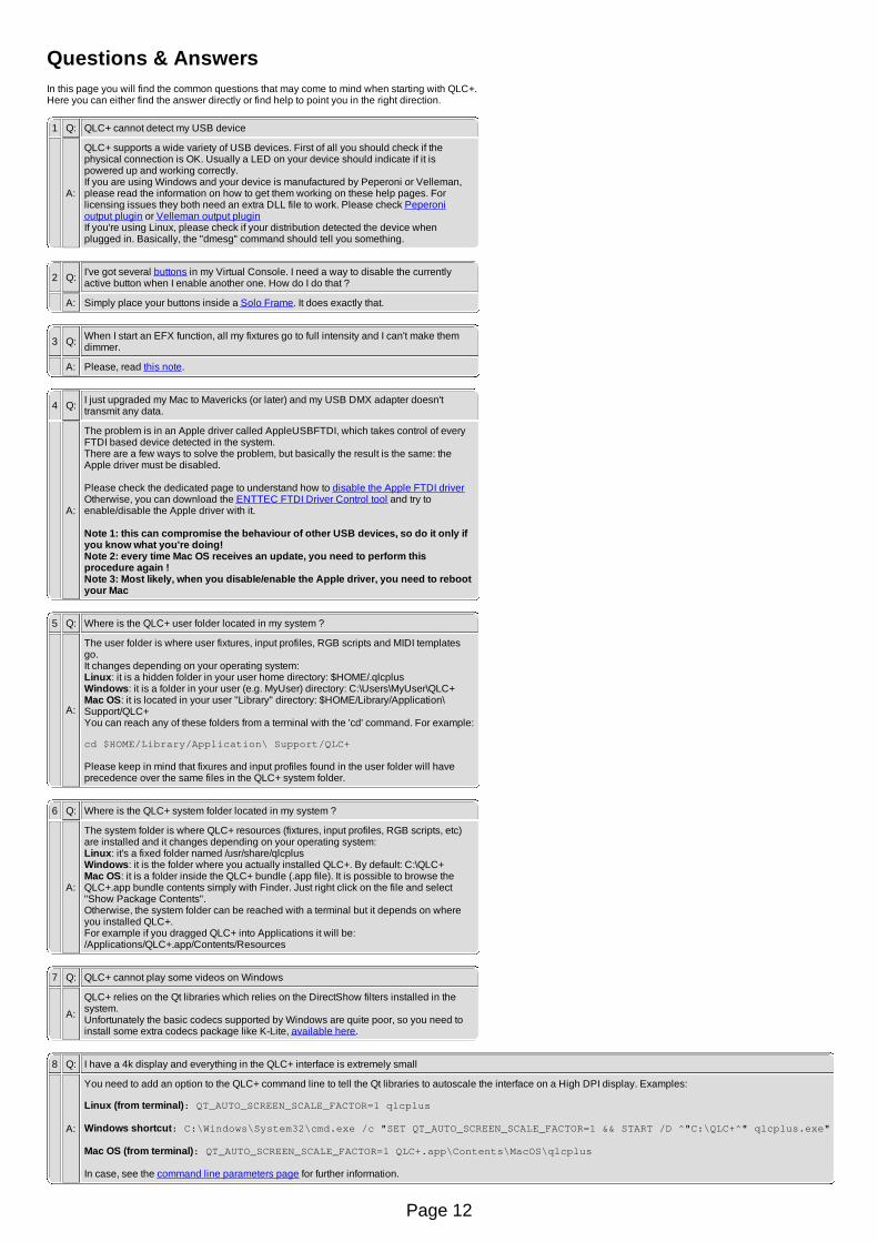
Questions & AnswersIn this page you will find the common questions that may come to mind when starting with QLC+.Here you can either find the answer directly or find help to point you in the right direction.
1 Q: QLC+ cannot detect my USB device
A:
QLC+ supports a wide variety of USB devices. First of all you should check if thephysical connection is OK. Usually a LED on your device should indicate if it ispowered up and working correctly.If you are using Windows and your device is manufactured by Peperoni or Velleman,please read the information on how to get them working on these help pages. Forlicensing issues they both need an extra DLL file to work. Please check Peperonioutput plugin or Velleman output pluginIf you're using Linux, please check if your distribution detected the device whenplugged in. Basically, the "dmesg" command should tell you something.
2 Q: I've got several buttons in my Virtual Console. I need a way to disable the currentlyactive button when I enable another one. How do I do that ?
A: Simply place your buttons inside a Solo Frame. It does exactly that.
3 Q: When I start an EFX function, all my fixtures go to full intensity and I can't make themdimmer.
A: Please, read this note.
4 Q: I just upgraded my Mac to Mavericks (or later) and my USB DMX adapter doesn'ttransmit any data.
A:
The problem is in an Apple driver called AppleUSBFTDI, which takes control of everyFTDI based device detected in the system.There are a few ways to solve the problem, but basically the result is the same: theApple driver must be disabled.
Please check the dedicated page to understand how to disable the Apple FTDI driverOtherwise, you can download the ENTTEC FTDI Driver Control tool and try toenable/disable the Apple driver with it.
Note 1: this can compromise the behaviour of other USB devices, so do it only ifyou know what you're doing! Note 2: every time Mac OS receives an update, you need to perform thisprocedure again !Note 3: Most likely, when you disable/enable the Apple driver, you need to rebootyour Mac
5 Q: Where is the QLC+ user folder located in my system ?
A:
The user folder is where user fixtures, input profiles, RGB scripts and MIDI templatesgo.It changes depending on your operating system:Linux: it is a hidden folder in your user home directory: $HOME/.qlcplusWindows: it is a folder in your user (e.g. MyUser) directory: C:\Users\MyUser\QLC+Mac OS: it is located in your user "Library" directory: $HOME/Library/Application\Support/QLC+You can reach any of these folders from a terminal with the 'cd' command. For example:
cd $HOME/Library/Application\ Support/QLC+
Please keep in mind that fixures and input profiles found in the user folder will haveprecedence over the same files in the QLC+ system folder.
6 Q: Where is the QLC+ system folder located in my system ?
A:
The system folder is where QLC+ resources (fixtures, input profiles, RGB scripts, etc)are installed and it changes depending on your operating system:Linux: it's a fixed folder named /usr/share/qlcplusWindows: it is the folder where you actually installed QLC+. By default: C:\QLC+Mac OS: it is a folder inside the QLC+ bundle (.app file). It is possible to browse theQLC+.app bundle contents simply with Finder. Just right click on the file and select"Show Package Contents".Otherwise, the system folder can be reached with a terminal but it depends on whereyou installed QLC+.For example if you dragged QLC+ into Applications it will be:/Applications/QLC+.app/Contents/Resources
7 Q: QLC+ cannot play some videos on Windows
A:
QLC+ relies on the Qt libraries which relies on the DirectShow filters installed in thesystem.Unfortunately the basic codecs supported by Windows are quite poor, so you need toinstall some extra codecs package like K-Lite, available here.
8 Q: I have a 4k display and everything in the QLC+ interface is extremely small
A:
You need to add an option to the QLC+ command line to tell the Qt libraries to autoscale the interface on a High DPI display. Examples:
Linux (from terminal): QT_AUTO_SCREEN_SCALE_FACTOR=1 qlcplus
Windows shortcut: C:\Windows\System32\cmd.exe /c "SET QT_AUTO_SCREEN_SCALE_FACTOR=1 && START /D ^"C:\QLC+^" qlcplus.exe"
Mac OS (from terminal): QT_AUTO_SCREEN_SCALE_FACTOR=1 QLC+.app\Contents\MacOS\qlcplus
In case, see the command line parameters page for further information.
Page 12

Main WindowThe QLC+ Main Window consists of three main parts:
1. A Menu bar containing buttons for global functions2. Active panels selected by their respective tabs3. Tabs that allow the selection of one of the QLC+ panels
Most of the controls throughout the software have tooltips, which pop up after holding your mousecursor over them for a short while.
Menu bar (1)The menu bar on the top of the workspace window contains the following buttons (from left toright):
New workspace (CTRL+N)
Open an existing workspace (hold the button longer for a list of recent files) (CTRL+O)
Save the current workspace (CTRL+S)
Save the current workspace with a new name
DMX Monitor (CTRL+M)
DMX Address tool
Audio triggers
Page 13
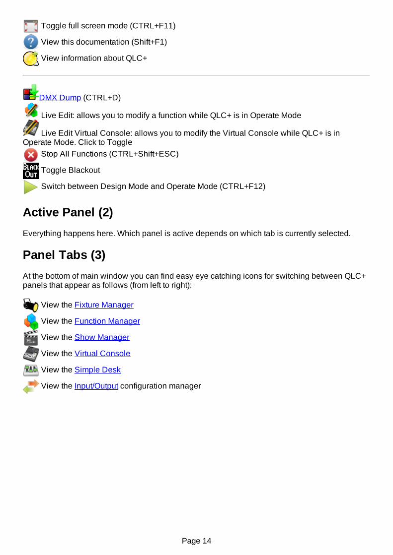
Toggle full screen mode (CTRL+F11)
View this documentation (Shift+F1)
View information about QLC+
DMX Dump (CTRL+D)
Live Edit: allows you to modify a function while QLC+ is in Operate Mode
Live Edit Virtual Console: allows you to modify the Virtual Console while QLC+ is inOperate Mode. Click to Toggle
Stop All Functions (CTRL+Shift+ESC)
Toggle Blackout
Switch between Design Mode and Operate Mode (CTRL+F12)
Active Panel (2)Everything happens here. Which panel is active depends on which tab is currently selected.
Panel Tabs (3)At the bottom of main window you can find easy eye catching icons for switching between QLC+panels that appear as follows (from left to right):
View the Fixture Manager
View the Function Manager
View the Show Manager
View the Virtual Console
View the Simple Desk
View the Input/Output configuration manager
Page 14

DMX MonitorThe DMX Monitor is a useful tool to track the values that are being sent to the output universes.Only the information related to the required fixtures are displayed. The monitor's display optionshave no effect on actual fixture addressing, after all, it is just a monitor.The DMX monitor has two display modes: DMX view and 2D view.
DMX viewThe DMX view shows the all the fixtures of the project, representing each channel with numbersand icons. It basically represents each channel in 3 rows:
The channel group iconThe channel numberThe channel value
Toolbar controls
2D View By clicking on this button, it is possible to switch to the 2D view mode.
Change the monitor font. To prevent the numbers from flickering and jumping, youshould choose a proportional (i.e. fixed width) font; for example Monaco, Andale orCourier. The font property is global, meaning it will not be saved into your currentproject, but it will be stored in the QLC+ main configuration.
DMXChannels
Display fixtures' channel numbers as absolute DMX channels; channel numbersgo from 1 to 512 as they are assigned to each fixture.
RelativeChannels
Display fixtures' channel numbers relative to fixtures i.e. every fixture's channelnumbers always start from 1.
DMXValues Display channel values as absolute DMX values (0-255).
PercentValues Display channel values as percentages of 255 (0-100%).
Universe Select which universe to monitor. The first entry is always "All universes"
2D viewThe monitor 2D view is another way to represent the fixtures of your project that, instead ofnumbers, uses a graphical preview trying to represent as much as possible the real result of alight-emitting device.
Currently, monitor reflects:
Master DimmerR/G/BC/M/YColor wheels, if they contain RGB color value. Two-color values are not supportedShutter, which is open, unless the capability name contains "close" or "blackout" (example:"Shutter Close")
Page 15

In 2D view mode it is possible to select which fixtures to display and their position in a gridrepresenting the dimensions of a real stage.The grid would like to reproduce the front view of a stage, but you can use it as a generic spaceas you might like.Graphical items can be manually moved by dragging them over the grid, or, when clicked, theycan be configured with the Monitor Fixture Editor panel that will be displayed on the right side ofthe window.
Toolbar controls
DMX View By clicking on this button, it is possible to switch to the DMX view mode.
Griddimensions
Set the width and the height of the 2D view grid by changing the valuesdisplayed in the two spin boxes
Grid units Set the 2D view grid measurement units by selecting the desired one from thedrop down menu. Possible options are meters and feet.
Add a fixture to the 2D view grid. When clicking on this icon, the fixture selectiondialog will be displayed. Fixtures already added to the view will be greyed as itisn't possible to add the same fixture twice
Remove a fixture from the 2D view grid. Clicking on this icon will remove thecurrently selected fixture. A fixture is highlighted in yellow when selected.
Open the Monitor background picture selection dialog.Here it is possible to choose between 3 possible modes:
No background: the Monitor 2D view won't have any background pictureCommon background: the Monitor 2D view will display the chosenbackground pictureCustom background list: in this mode it is possible to select abackground picture for a specific QLC+ Function. Just click on the
and buttons to add/remove Functions and their associated
background picture to the Monitor. When a Function in this list will start theMonitor 2D view background picture will change accordingly.
Show/hide fixtures' names underneath their graphical representation
Fixture Item Editor
When a fixture is clicked, it gets highlighted in yellow and the Monitor Fixture Item Editor isdisplayed on the right side of the window.Following, the possible parameters that it is possible to tune:
Horizontalposition Set the position on the grid X axis using the grid measurement units
Verticalposition Set the position on the grid Y axis using the grid measurement units
Rotation Set the rotation angle of the graphical item representing the selected fixture
Set the color gel to be applied to the currently selected fixture item. This is useful
Page 16

Color gel for generic dimmers with a traditional light bulb, not emitting any color by itself.This function has no effect on RGB LED fixtures.
Reset a previously set color gel
Pan/Tilt display
PAN/TILT display is schematically displayed using colored rings/arcs around fixture. Purple arcshows PAN angle, and Turquoise arc shows TILT angle. Gray dots show PAN/TILT ranges. Zero(middle of the range) is at the bottom.
In the folowing picture PAN range is 660 degrees and tilt range is 300 degrees. Pan is at counter-clockwise end (-330 deg) and tilt is at -150 deg.
Page 17

DMX Address ToolThe DMX address tool is a quite easy/self explanatory functionality of QLC+ introduced inversion 4.3.2.It helps you to calculate your fixtures addresses quickly in a visual way.A representation of a common 10way DIP switch is displayed and you can select the backgroundcolor, the horizontal and vertical orientation, so that the DIP switch is displayed exactly as youwould see it on your fixture.
Note particularly the following, which applies to the 10th switch. Usually, it is used toenable/disable the DMX feature of a fixture, so if your product manual says it has to be raised toenable the DMX control, then remember to do it even if QLC+ displays it set to OFF.
Page 18
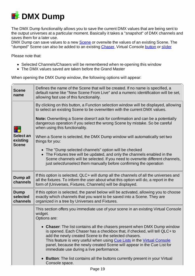
DMX DumpThe DMX Dump functionality allows you to save the current DMX values that are being sent tothe output universes at a particular moment. Basically it takes a "snapshot" of DMX channels andsaves them for a later use.DMX Dump can save values to a new Scene or overwite the values of an existing Scene. The"dumped" Scene can also be added to an existing Chaser, Virtual Console button or slider
Please note that:
Selected Channels/Chasers will be remembered when re-opening this windowThe DMX values saved are taken before the Grand Master
When opening the DMX Dump window, the following options will appear:
Scenename
Defines the name of the Scene that will be created. If no name is specified, adefault name like "New Scene From Live" and a numeric identification will be set,allowing fast use of this functionality.
Select anexistingScene
By clicking on this button, a Function selection window will be displayed, allowingto select an existing Scene to be overwritten with the current DMX values.
Note: Overwriting a Scene doesn't ask for confirmation and can be a potentiallydangerous operation if you select the wrong Scene by mistake. So be carefulwhen using this functionality.
When a Scene is selected, the DMX Dump window will automatically set twothings for you:
The "Dump selected channels" option will be checkedThe Fixtures tree will be updated, and only the channels enabled in theScene channels will be selected. If you need to overwrite different channels,just select/unselect them manually before confirming the operation
Dump allchannels
If this option is selected, QLC+ will dump all the channels of all the universes andall the fixtures. To inform the user about what this option will do, a report in theform of (Universes, Fixtures, Channels) will be displayed.
Dumpselectedchannels
If this option is selected, the panel below will be activated, allowing you to chooseexactly which channels that you want to be saved into a Scene. They areorganized in a tree by Universes and Fixtures.
This section offers you immediate use of your scene in an existing Virtual Consolewidget.Options are:
Chaser: The list contains all the chasers present when DMX Dump windowis opened. Each Chaser has a checkbox that, if checked, will tell QLC+ toadd the newly created Scene to the selected chasers.This feature is very useful when using Cue Lists in the Virtual Consolepanel, because the newly created Scene will appear in the Cue List forimmediate use during a live performance.
Button: The list contains all the buttons currently present in your VirtualConsole space.
Page 19

Add to When selected, the buttons will be set to activate/deactivate the Scene justcaptured. You will see the button label chaning to "Scene from live ..." and aprogress number to identify it.Note: Any previous function associated to the selected buttons will beoverwritten !
Slider: The list contains all the sliders currently present in your VirtualConsole space.As with buttons, all the selected sliders will be set to control the Scene justcaptured.Note 1: A slider must be in playback mode to work as an intensitycontroller for a Scene.Note 2: Any previous function associated with the selected sliders will beoverwritten !
Dumponly non-zerovalues
This option will tell QLC+ to save only the channels with values that are not equalto zero.If you know what you're doing, this could save project space and avoid channelsconflicts with other Virtual Console widgets.
Page 20

Live EditStarting from version 4.5.0, QLC+ offers a functionality which allows the adjustment of yourFunctions while in Operate Mode.
The Live Edit icon is located in the QLC+ top bar, beside the DMX Dump icon and it isactivated only when the user has switched to Operate Mode.When clicking on the Live Edit icon, a Function selection panel will be displayed, allowing theselection of the function you want to adjust.When you press OK, the correct editor will be displayed for editing that function.At the moment, the following functions are supported for live editing:
Scene will open a Scene EditorNote that by default the editor will be set in "Blind mode" when you edit a Scene that is notcurrently running, in case you want to make the changes effective only when the Scene isbeing replayed the next time it is selected. For a currently running Scene the editor willopen in live mode by default.
Chaser will open a Chaser Editor
EFX will open an EFX Editor
RGB Matrix will open an RGB Matrix Editor
The types of functions listed in the Function selection can be selected by using the filtercheck boxes at the bottom of the panel.There is an option at the top of the panel to list currently running functions only.
Note that if another function is running when performing a live edit, HTP channels in theother function may prevent some adjustments from being seen on the stage.
Page 21

Fixture ManagerThe fixture manager is the heart of QLC+'s fixture-oriented architecture. As its name already says,you can manage (add, remove and edit) your lighting fixtures from the fixture manager. On the leftside of the manager there is a list that displays all of the fixtures in the current workspace. Whena fixture is selected, the right side of the window displays the details of the selected fixture. Whena Fixture Group is selected, the right side of the window is occupied by the Fixture Group Editor.
Controls
Add new Fixture(s) to the workspace with the Add/Edit Fixture dialog.
Add a RGB panel to the workspace with with the Add RGB Panel dialog.
Remove the selected fixtures from the workspace. This also removes the fixtures fromALL groups they have been assigned to.
Edit the currently selected fixture's properties with the Add/Edit Fixture dialog.
Opens the Channel Properties Configuration window.
Assign the selected fixtures to a Fixture Group displayed in a popup menu. If you haveno groups defined yet, you can choose to create a new one from the menu that openswhen this button is clicked.
Resign (remove) the selected fixtures from the group they are currently in. Note thatremoving fixtures from a group will NOT destroy the fixtures completely. Also, removalfrom one group will not affect the fixtures' memberships to other groups.
Move the selected Channel Group up
Move the selected Channel Group down
Imports a fixture list file (.qxfl) into QLC+. Please note that fixture addresses conflicts arenot handled, so it is suggested to use this functionality on an empty project.
Exports the list of fixtures currently available on a QLC+ project into a file with extension.qxfl. This file can be used afterward with the import functionality.
Opens the Fixtures remapping window.
Page 22

Add/Edit FixturesThe same dialog (with slight differences) is used for both adding new and editing the propertiesof existing Fixtures.
NOTE: When editing an existing fixture, you can always choose a completely different fixturetype to replace the previous one, but if their channels don't match each other exactly, any Scenefunctions you may have created, will very probably do things that you don't want. Also, if thechannel counts don't match, you might end up having fixtures with overlapping channels, whichresults also to unwanted behaviour. RGB Matrix, EFX, Chaser and Collection functions remainunaffected since they don't directly address specific channels, but are more dynamic in nature.
Controls
FixtureModel list
Shows you a list of available fixture definitions and their general types. If you don'tsee your favourite fixture definition on the list, you can create one yourself with theaccompanying, easy to use QLC+ Fixture Editor. Since QLC+ is completely freesoftware, please consider sharing the definition files with the community athttp://www.qlcplus.org/forum/viewforum.php?f=3
FixtureProperties
Name: The friendly name you wish to assign to the fixtureMode: The mode you have configured to the fixtureUniverse: The DMX universe where the newly-added fixture(s) areconnected toAddress: The address of the (first) fixture you are adding. If you are addingmultiple fixtures, each consecutive fixture will be assigned an addressimmediately after the previous fixture's channels, unless address gap (seebelow) is non-zero.Channels: If you have selected the Generic dimmer device, you can defineits channel count to this field. Otherwise this field is read-only and it just tellsyou how many channels the currently selected fixture needs in its currentlyselected mode.Channel list: This field displays a more detailed list of individual channelsfor the currently selected fixture and its mode. For Generic dimmers, thisfield remains empty since all dimmer channels are treated as dummyintensity channels.
MultipleFixtures
You can also add more than one fixture at the same time if your setup consists ofmultiple fixtures that are of the same make & model. These features are disabledwhen you are editing an existing fixture.
Amount: Number of new fixtures to create. Each newly-added fixtureincludes also a number after its assigned name when adding more than onefixture at a time.Address gap: Leave this many empty channels between each new fixture
Page 23

Add RGB PanelOn the market you can easily find LED strips that you can wire as you prefer to create a RGBPanel (or matrix). This dialog allows you to quickly create and setup a RGB Panel. It is adedicated dialog to help you with the most annoying process of creating fixtures manuallydepending on the desiderd layout.Please note that once the panel is created, the only way to modify the layout is manually.
Panel creationWhen clicking OK on this dialog two things will happen:
QLC+ will create a fixture for each row of the panel. They can be considered like if thepanel is composed by individual RGB bars.QLC+ will create a fixture group representing the panel with heads already in the rightdisplacement
Once a RGB panel is created, it is straight forward to go to the Function Manager, create a newRGB Matrix and start using the panel very quickly.
Let's have a look at every option in this panel:
Panel Properties
Name An arbitrary string that can be used to name the RGB panel
UniverseThe universe where the RGB Panel is going to start. If the panel requires anumber of channels that don't fit in a single universe, it will span across multipleuniverses, starting from the one selected with this option.
Address The DMX start address where the RGB Panel has to be mapped
Size
Columns The RGB Panel number of columns (or the number of pixels per row)
Rows The RGB Panel number of rows (or the number of pixels per column)
Physical
Width The physical width in millimeters of the RGB Panel
Height The physical height in millimeters of the RGB Panel
Orientation
Top-Left The first pixel will be located on the top-left corner of the panel
Top-Right The first pixel will be located on the top-right corner of the panel
Bottom-Left The first pixel will be located on the bottom-left corner of the panel
Bottom-Right The first pixel will be located on the bottom-right corner of the panel
Displacement
Page 24
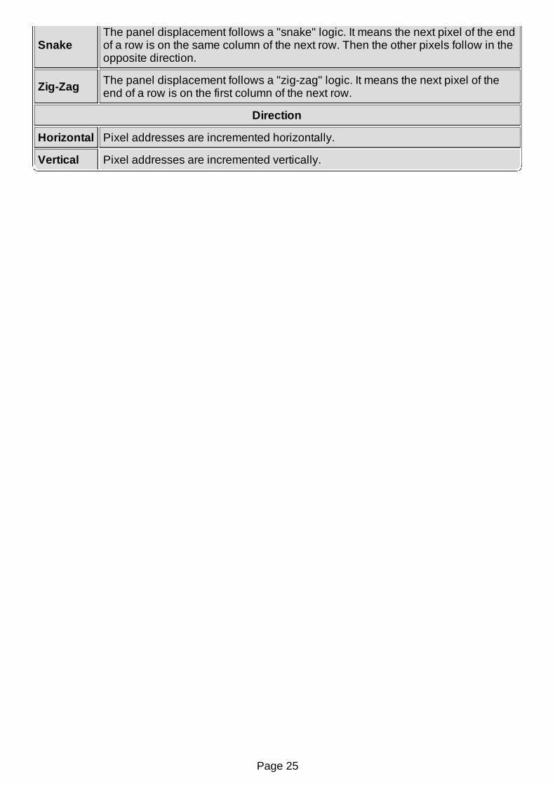
SnakeThe panel displacement follows a "snake" logic. It means the next pixel of the endof a row is on the same column of the next row. Then the other pixels follow in theopposite direction.
Zig-Zag The panel displacement follows a "zig-zag" logic. It means the next pixel of theend of a row is on the first column of the next row.
Direction
Horizontal Pixel addresses are incremented horizontally.
Vertical Pixel addresses are incremented vertically.
Page 25

Fixture Group EditorThe Fixture Group Editor is used when you select a Fixture Group in the Fixture Manager. Thiseditor can be used to describe the physical arrangement of the fixtures and their heads that areassigned to the group.
Controls
Each Fixture Group has a name (for your convenience) and the fixture configuration in anunlimited [X,Y] grid. You can adjust the size of the grid as well as the placement of individualfixture heads on the grid.
FixtureGroupName
Change the name of the group.
Add fixture heads to the currently selected row, filling each subsequent column onthat row with the selected fixture heads. You can select individual fixture heads orcomplete fixtures to be added on the selected row.
Add fixture heads to the currently selected column, filling each subsequent row onthat column with the selected fixture heads. You can select individual fixture heads orcomplete fixtures to be added on the selected column.
Remove the selected fixture head from the grid (and the group).
Fixturegrid
The fixture grid displays the current fixture/head arrangement in the selected group.You can switch places between two heads as well as fill up spaces or create emptyspaces between heads simply by dragging the heads on top of each other in the grid.
When using fixture groups in RGB Matrices, each cell in the grid represents onecolored (or monochrome) pixel in a graphic scene rendered by the RGB Matrix.
Each cell is displayed with an info text that contains the following information:
The name of the fixture as well as an iconH: represents the head numberA: represents the fixture's addressU: represents the fixture's universe
Width Adjusts the grid width (number of columns on the X-axis).
Height Adjusts the grid height (number of rows on the Y-axis).
Page 26

Channel Groups EditorThe Channel Groups editor it activated by clicking on the "Channels Groups" tab in the FixtureManager panel.With this functionality (introduced in QLC+ version 4.0.0), it is possible to create groups ofchannels with the same functionality.For example, if you have 20 PARs you might want to control the RED channel of all of them witha single fader.
Controls
Add a new channels group to the workspace with the Add/Edit Channels Group dialog.
Remove the selected channels group from the workspace.
Edit an existing channels group in the workspace with the Add/Edit Channels Groupdialog.
Move the selected group up in the list to change the logical order.
Move the selected group down in the list to change the logical order.
Add/Edit Channels Group
Group Name Set/change name of the channels group
Channels list Check channels that should be included in this channels group. Uncheckthose that should not.
Apply changesto all fixtures ofthe same type
When checked, clicking on a channel will select/deselect the same channelon all fixtures of the same type. Use it when you want to select e.g. all Redchannels of all fixture of a particular LED PAR model
External input Select external input for this channels group for easier control in FunctionManager. External input for channels groups will not work elsewhere.
Page 27

Channel Properties ConfigurationThis window displays a tree with items nested in a Universes/Fixtures/Channels structure.On the right side of each fixture's channel are displayed the available options that can be set tomodify the behaviour of each single channel.
Channels properties
Can fade
Determine if a channel is included or excluded in the QLC+ fade transitions.By default all the channels are affected by the Fade In and Fade Out timings ofthe QLC+ functions.When this property is unchecked, a channel will not fade, meaning that a fadetransition from 20 to 200, will set the channel immediately to 200.This is useful for example for Pan/Tilt channels of moving heads, where you wantthe motors to avoid fading but immediately go to the final value.
Behaviour
Force the channel behaviour according to the HTP and LTP rules. Whenchanging the behaviour of a channel, the dropdown list will highlight in red,showing evidence that the channels has been modified.Note: Use this functionality only if you know what you're doing and fullyunderstand how HTP and LTP work
Modifier
Channels modifiers are a powerful tool to modify the behaviour of a channel byacting at the end of the DMX value calculation, right before the Grand Mastermodification.By default all the channels will follow a linear rule, meaning that the original DMXvalue will be equal to the output DMX value. (0-0, 1-1, ... , 255-255)When clicking on this button, the Channel Modifier Editor panel (described below)will be displayed.
When dealing with a lot of fixtures of the same type, you might want to check the "Apply changesto fixtures of the same type" check box.This means that changing a channel property will affect all the channels of the same type andfixture in the list.This can save you quite a lot of time when setting up your projects for the first time.
Channel Modifier EditorThe channel modifier editor is presented like this:
Page 28

On the right side of the window, a list of available modifier templates is displayed.Clicking on a template in the list, will show the curve preview on the left side of the window.A modifier curve is composed by a number of lines representing how a DMX channel should bemodified when its value changes.Each line starts and ends with a so called "handler". A modifier can have a virtually infinitenumber of handlers, but there must be always one handler on the DMX value 0 and one handleron the DMX value 255 to cover all the DMX values range.Basically the X coordinate of the preview represents the original DMX value and the Y coordinaterepresents the modified DMX value.When clicking on a handler this gets clearer as the fields above the curve preview are filled withthe said values.Handlers can be simply moved with the mouse by dragging them around or by manuallychanging the values of the original or modified DMX values.
To create a new template just select an existing template, give it a new name and add/remove
handlers as needed with the and buttons.
When done, just click the button and your template will be saved in your user templatesfolder. Please refer to the Questions and Answers page to locate this folder.
Channel Modifier TemplatesQLC+ delivers a few templates that might cover the most common cases.
Always FullFix ("park") the channel value to 100% (255), regardless of other QLC+mechanisms (except blackout and universe passthrough). Useful for e.g.dimmer channels.
Always Half Fix ("park") the channel value to 50% (127). Useful for keeping Pan/Tiltchannels at a neutral position.
Always Off Fix ("park") the channel value to 0% (0). Useful for disabling wrong fixtures.
ExponentialDeep
Page 29
ExponentialMedium
ExponentialShallow
ExponentialSimple
Inverted Invert a Pan/Tilt channel where a product doesn't have this feature by factorydefault.
Linear Default curve, same as when no modifier is set.
LogarithmicDeep
This template can improve the fade transitions of LED-based fixtures, trying tobring them back to a more linear effect
LogarithmicMedium
LogarithmicShallow
Preheat 5% May extend lamp life by keeping them at 5% minimum
Threshold Converts dimmer channel to switch channel (off below 128, full above)
Page 30

Fixtures remappingStarting from version 4.4.1, QLC+ offers a functionality called fixtures remapping.When performing live shows in different venues, you may only be able to find out at the lastminute which fixtures are installed there. Well, fixtures remapping helps you to use your existingprojects in this and many other situations, such as when you need to replace a faulty fixture orwhen you want to use hired in equipment alongside your own.For example, you can set up a project with just one PAR, one moving head and one scanner.When reaching the venue where the show is going to take place, you can remap your fixtures tothose you find there, for example 50 PARs, 30 moving heads and 15 scanners.With QLC+, it takes just a few minutes to do this operation !
Fixtures remapping allows you to perform 1-to-1 or 1-to-many reassignments of entire fixtures orsingle channels. QLC+ will try as far as possible to reassign the original channels used in theproject to new channels in the same category.When you confirm the remapping operation, a new project will be automatically saved topreserve your original project.All the fixtures, scenes, EFX, Virtual Console widgets and audio triggers found in the originalproject will be remapped so that they work on the new fixtures list.
Remapping windowLet's now explain how to use the fixture remapping window, starting from a screenshot of acomplete example:
And now, here is a detailed explanation of each element of the remapping window.
Sourcefixtures
On the left side of the window, there is a tree representing the universes, fixturesand channels used in your project. This list cannot be changed in this window.
Page 31

Remappedfixtures
On the right side of the window, there is a tree representing the universes,fixtures and channels where you are going to remap your source fixtures.
Add one or more fixtures to the Remapped fixtures list. Clicking this button willopen the Add/Edit Fixtures window. Please note that once a fixture is added, itcannot be modified, so if you need specific names or quantity, remember to do itbefore adding the new fixtures
Remove the selected Fixture from the remapped fixtures list.
This is probably the most important button in the window. It allows you todetermine the connection between a source ficture and a remapped fixture. Theconnections can be performed either between single channels or on wholefixtures.In the first case you will need to select the source channel from the sourcefixtures list and a target channel from the remapped fixtures list.In the second case you will need to select a fixture from the source fixtures listand a target fixture from the remapped fixtures list.Wrong selections will cause an error message to popup. For example youcannot remap a channel to a fixture and vice-versa.If the connection is valid, it will be represented as a line in the white areabetween the source list and the remapped list.
Remove a previously created remapping connection. Wrong selections willcause an error popup.
Remapfixturesnames
If this is checked, a new remapping connection between fixtures will also set thetarget fixture name be the same as the source fixture name.
Destinationprojectname
The absolute path and name of the remapped project. For convenience, QLC+will automatically take the original project name and will add "(remapped)" at theend of it.
Page 32
Adding FixturesFixture Manager
Open the fixture manager by clicking its button on the main toolbar. Alternatively youcan select Fixtures from the Manager menu.
The fixture manager is the heart of QLC+ fixture-oriented architecture. As its name already says,you can manage (add, remove and edit) your lighting fixtures from the fixture manager. On the leftside of the manager there is a list that contains all of the fixtures in the current workspace(currently it's empty). On the right side you can see some common information related to thecurrently selected fixture. On top of the fixture manager there is again another toolbar, containingthe following buttons (from left to right):
Add new fixtures
Remove selected fixtures
Configure the selected fixture
Group a fixture selection
Ungroup a fixture from a group
Import a previously saved list of fixtures
Export a list of fixtures
Adding a fixture
Add a fixture to the workspace by clicking the add button.
On the left side of the dialog you can see a list of available fixture manufacturers. Eachmanufacturer item is actually a folder containing a number of fixture models produced by themanufacturer. You can find for example a "DJScan250" under the "Futurelight" folder. As youclick a fixture from the list, you can see the Channels field on the right side change to display thenumber of DMX channels required by the selected fixture. There's also a list of the fixture'schannels just under the Channels box.
You can edit the new fixture's name in the Name field or you can stick to the default that theapplication suggests. If the fixture has different operational modes (different sets of channels),you can select one from the Mode box. The fixture's DMX address can be set in the Address fieldand should be the same as the actual physical fixture's DMX address. The Universe field is usedto assign the fixture to a physical DMX output universe. Usually each universe has its own cablecoming from the computer.
If you wish to add multiple fixtures of the same type, you can increase the value in the Amountbox. If you wish to leave some gap between each fixture's address space, you can change thevalue in the Address gap box.
If you don't understand the DMX addressing principles, please consult your lighting equipmentPage 33
manuals for more information. In short, a DMX address is the first DMX channel of one fixture. Inthe case of a DJScan250 (which uses 6 channels), assigning for example 1 as its DMX address,reserves channels 1, 2, 3, 4, 5, and 6 to the fixture. The next fixture must then be assigned toDMX address 7 to prevent channel overlapping.
Adding a generic dimmer
Dimmers are a bit special devices, since all they can usually do is just adjust the intensities oftheir channels (that usually drive PAR cans and the like). If you wish to add such a device, selectthe Generic dimmer fixture from the list and specify the number of channels you wish the deviceto employ into the Channels box. Note that you cannot adjust the mode for dimmers and thechannel list stays empty all the time.
Back to the fixture managerClick OK to close the dialog and add the selected fixture(s) to the workspace.
On the left side of the fixture manager you can now see the fixture(s) that you just added. On theright side, you can see information on the currently selected fixture. You can edit the fixture'sname, address and universe by clicking the Configure button. You can also change the fixturedefinition thru the configuration dialog.
Page 34

Function ManagerWith the function manager you can manage all of your functions that do the actual work ofautomating your lights. You can create new functions, remove and edit existing ones as well ascreate copies of them. Controls are on the upper part of the window; the lower part displays all ofyour functions as well as the function editor for the currently selected function (if any).
Each function type can be found under its own category: Scene for scenes, EFX for EFX's etc.When a new function is created or an existing one selected, the appropriate editor is chosen anddisplayed on the right hand side of the Function Manager window. Changes made in the editorpane are stored immediately in the functions themselves and no additional OK clicks arerequired.
Controls
Create a new Scene and edit it using the Scene Editor.
Create a new Chaser and edit it using the Chaser Editor.
Create a new Sequence and edit it using the Chaser Editor.
Create a new EFX and edit it using the EFX Editor.
Create a new Collection and edit it using the Collection Editor.
Create a new RGB Matrix and edit it using the RGB Matrix Editor.
Create a new RGB Script and edit it using the RGB Script Editor.
Create a new Audio function to be used in Chasers or Shows.
Create a new folder in the selected category. A folder can be renamed by doubleclicking on it.When a folder is selected, a newly created function will be added to it. To move existingfunctions inside a folder, just select and drag them into it. In the same way they can bemoved outside a folder by dragging them onto a category item.When deleting a folder, all the functions and subfolders contained into it will be deletedas well.Note: Empty folders will not be saved into your project.
Open the Function selection dialog to choose a startup function. The selected functionwill be started every time QLC+ switches to operate mode. This is very useful whenrunning QLC+ in kiosk mode (thus using -k or -p flags)A special entry named "<No function>" is present to remove a previously set startupfunction.
Start the Function Wizard.
Create a copy of each of the selected functions.
Page 35
Permanently remove the selected function(s).
Page 36

Scene EditorThe scene editor, as its name suggests, is used to edit Scene functions. The editor is
divided into tabs; with the first, General tab, you control the list of fixtures and channel groups thattake part in the scene editing, together with the Scene name.All subsequent tabs are used to control the individual channel values for each fixture and, if anyare defined, the channels groups values.
General Tab ControlsOn the left hand part of the screen, the buttons to control the fixtures used in the scene aredisplayed.
Scene name Change the name of the scene.
Add an existing Fixture to the scene.
Remove the selected Fixture(s) from the scene.
Enable all channels of the selected fixtures.
Disable all channels of the selected fixtures.
On the right hand part of the screen, the buttons to control the channel groups used in the sceneare displayed
Enable all the selected channel groups.
Disable all the selected channel groups.
Hint: It's useful to know that when a channels group is checked/unchecked, the fixturescontrolled by the group will be automatically added to the left panel. The channels controlled bythe group will also be automatically enabled/disabled on each fixture.
Channel Groups TabsThis tab will be displayed only if one or more channel groups are selected in the General tab.Each Channel Group will be displayed with a quick macro access button (Click And Go ifsupported), a label with the group value, a fader and the name of the group.
Fixture TabsEach fixture is represented by its own tab that contains sliders for each of the fixture's channels.Each channel can be enabled or disabled with a check box at the top of the channel unit. Thevalue of each channel can be set either by typing the value to the edit box at the top of the slideror by moving the slider. Channels that provide multiple functions such as gobos, colors, etc. alsohave a button above the channel slider - this button can be used to directly select a specific
Page 37

function or capability provided by that channel.Hint: The keyboard shortcut to move between channels values edit boxes is 'Tab' to move to theright and 'Shift + Tab' to move to the left.
Channel enabled/disabled status
If a channel has not been enabled, the scene will not touch that particular channel's value, ever.
If a channel has been enabled, the scene will change that channel's value to the value that isdefined in the scene. This is useful, for example, when you wish to control only the dimmerchannel of a scanner fixture - you wouldn't want the scene to touch the scanner's pan, tilt, color orgobo channels when you just want to fade in or fade out with the dimmer channel.
Controls
Enable all channels from the current fixture. In all channels mode, select channels for allfixtures.
Disable all channels from the current fixture. In all channels mode, disable channels forall fixtures.
Go to the previous tab in the view. If the first tab is selected, this will go to the last tab inthe view. Keyboard shortcut: 'ALT+Left'
Go to the next tab in the view. If the last tab is selected, this will go to the first tab in theview. Keyboard shortcut: 'ALT+Right'
The Copy functionality has 2 modes:
Copy the values (and enabled/disabled states) of all channels in the current fixtureto the clipboard.Copy only the selected channels (CTRL-clicked, yellow background) values intothe clipboard.
Paste the values from clipboard to the current fixture. If no channels were selectedduring 'copy', then all the enabled/disabled states will be pasted along with the channelvalues.
The 'Copy all' functionality has 2 modes:
Copy all values (and enabled/disabled states) of all channels to all other fixturestaking part in the scene.Copy only the selected channels (CTRL-clicked, yellow background) values to allthe other fixtures taking part in the scene.
Launch a color tool to select a specific color and set that color to the current fixture; Thisfeature is enabled only for fixtures that are capable of CMY/RGB color mixing.
Launch a position tool (similar to XYPad in Virtual console) to select a head/mirrorposition for the current fixture; This feature is enabled only for fixtures that have eitherpan or tilt channels. All heads of current fixture will be changed to the same value.
Show/Hide the Speed Dial widget, used to adjust the Scene parameters such as FadeIn and Fade Out
Switch between "tab view" and "all channels view". The first mode will display one tabfor each fixture, while the second will display a single tab for all the fixtures
Page 38

Toggle blind mode for the selected fixture.
Clone the current scene and add a new step to the Chaser selected from the drop downlist beside this button
Page 39
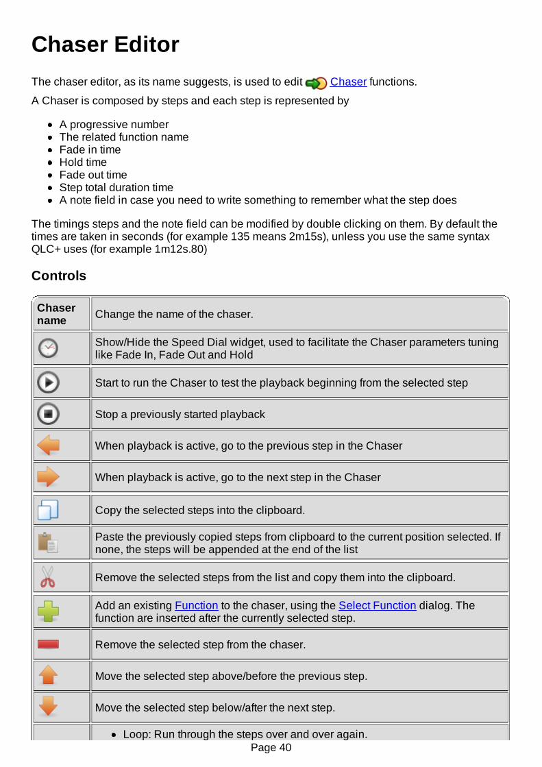
Chaser EditorThe chaser editor, as its name suggests, is used to edit Chaser functions.
A Chaser is composed by steps and each step is represented by
A progressive numberThe related function nameFade in timeHold timeFade out timeStep total duration timeA note field in case you need to write something to remember what the step does
The timings steps and the note field can be modified by double clicking on them. By default thetimes are taken in seconds (for example 135 means 2m15s), unless you use the same syntaxQLC+ uses (for example 1m12s.80)
Controls
Chasername Change the name of the chaser.
Show/Hide the Speed Dial widget, used to facilitate the Chaser parameters tuninglike Fade In, Fade Out and Hold
Start to run the Chaser to test the playback beginning from the selected step
Stop a previously started playback
When playback is active, go to the previous step in the Chaser
When playback is active, go to the next step in the Chaser
Copy the selected steps into the clipboard.
Paste the previously copied steps from clipboard to the current position selected. Ifnone, the steps will be appended at the end of the list
Remove the selected steps from the list and copy them into the clipboard.
Add an existing Function to the chaser, using the Select Function dialog. Thefunction are inserted after the currently selected step.
Remove the selected step from the chaser.
Move the selected step above/before the previous step.
Move the selected step below/after the next step.
Loop: Run through the steps over and over again.Page 40

RunOrder
Single Shot: Run through the steps once and then stop.Ping Pong: Run through the steps over and over again, reversing direction atboth ends.Random: Run through the steps over and over again in random order.
DirectionForward: Run through the steps from start to end; 1, 2, 3...Backward: Run through the steps from end to start; ...3, 2, 1
Fade InSpeed
Common: Apply the same speed for all the steps in this ChaserPer step: Apply a user defined speed for each step in this ChaserDefault: Apply the default speed for each step (0 seconds).
Fade OutSpeed
Common: Apply the same speed for all the steps in this ChaserPer step: Apply a user defined speed for each step in this ChaserDefault: Apply the default speed for each step (0 seconds).
StepDuration
Common: Apply the same duration for all the steps in this ChaserPer step: Apply a user defined duration for each step in this Chaser
Page 41

Show EditorThe Show Editor is a panel to display the current structure of a Show created with the Show
Manager.At the moment the Show Editor can only rename a Show, which is not possible in the ShowManager.
The tree view of this panel shows useful information regarding the displayed Show such as:
Function: the function nameSteps: the number of steps that compose a SequenceStart Time: the time at which a sequence is going to be reproducedDuration: the duration of the sequence
Page 42

EFX EditorThe EFX editor, as its name suggests, is used to edit EFX functions. The view is split into
two tabs:
General tab is for selecting Fixtures, speed and fixture order.Movement tab is for selecting details on how the fixtures should move their beams.
General Tab Controls
Adjust the EFX speed settings:
Fade In: Not used currentlyFade Out: Not used currentlyDuration: The duration of one full round using the selected pattern
Enable the output and run the EFX to test how it looks like
EFXname Change the name of the EFX.
Step: Shows the order in which the fixtures start their movement inserial/asymmetric order
Page 43
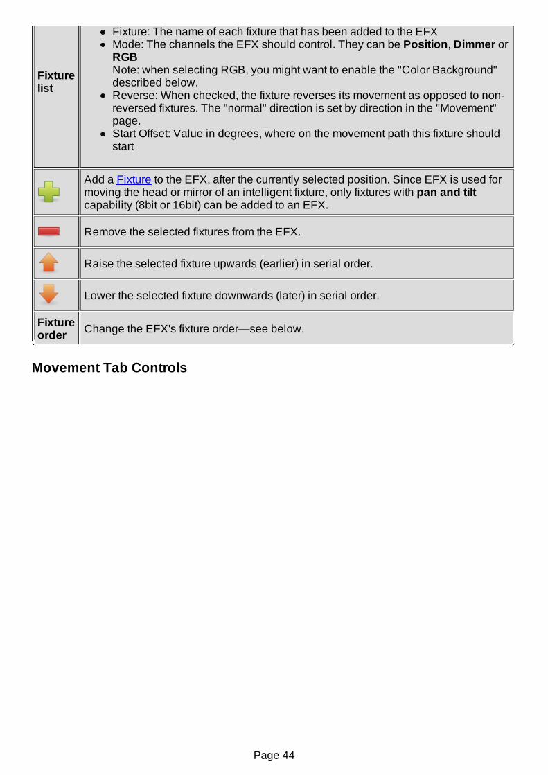
Fixturelist
Fixture: The name of each fixture that has been added to the EFXMode: The channels the EFX should control. They can be Position, Dimmer orRGBNote: when selecting RGB, you might want to enable the "Color Background"described below.Reverse: When checked, the fixture reverses its movement as opposed to non-reversed fixtures. The "normal" direction is set by direction in the "Movement"page.Start Offset: Value in degrees, where on the movement path this fixture shouldstart
Add a Fixture to the EFX, after the currently selected position. Since EFX is used formoving the head or mirror of an intelligent fixture, only fixtures with pan and tiltcapability (8bit or 16bit) can be added to an EFX.
Remove the selected fixtures from the EFX.
Raise the selected fixture upwards (earlier) in serial order.
Lower the selected fixture downwards (later) in serial order.
Fixtureorder Change the EFX's fixture order—see below.
Movement Tab Controls
Page 44

Patternarea
Shows a 2D-projection of the fixtures' head/mirror movement. Every time youchange a parameter, one small dot for each fixture travels the complete path inits selected direction from its start offset.
The speed of the movement reflects selected speed settings.
Direction
Default direction of the fixtures (can be altered individually for each fixture by thecheckbox in the Reverse column)
Forward: The fixtures move forwards along the pattern pathBackward: The fixtures move backwards along the pattern path
Run order
Loop: Run thru the steps over and over again.Single Shot: Run thru the steps once and then stop.Ping Pong: Run thru the steps over and over again, reversing direction atboth ends.
Pattern
Select the movement pattern algorithm.
CircleEightLine: goes from one end to the other and back; faster in the middle, slowerat the endsLine2: goes in one direction only; speed is always the same
Page 45
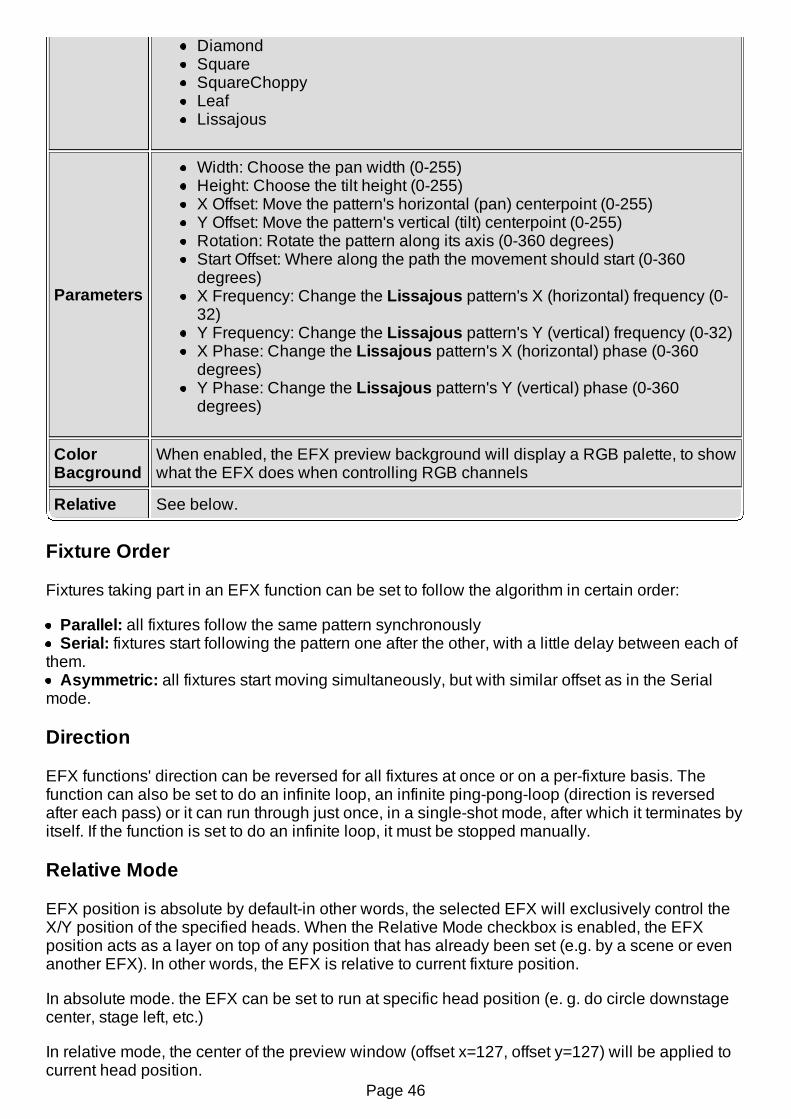
DiamondSquareSquareChoppyLeafLissajous
Parameters
Width: Choose the pan width (0-255)Height: Choose the tilt height (0-255)X Offset: Move the pattern's horizontal (pan) centerpoint (0-255)Y Offset: Move the pattern's vertical (tilt) centerpoint (0-255)Rotation: Rotate the pattern along its axis (0-360 degrees)Start Offset: Where along the path the movement should start (0-360degrees)X Frequency: Change the Lissajous pattern's X (horizontal) frequency (0-32)Y Frequency: Change the Lissajous pattern's Y (vertical) frequency (0-32)X Phase: Change the Lissajous pattern's X (horizontal) phase (0-360degrees)Y Phase: Change the Lissajous pattern's Y (vertical) phase (0-360degrees)
ColorBacground
When enabled, the EFX preview background will display a RGB palette, to showwhat the EFX does when controlling RGB channels
Relative See below.
Fixture Order
Fixtures taking part in an EFX function can be set to follow the algorithm in certain order:
Parallel: all fixtures follow the same pattern synchronouslySerial: fixtures start following the pattern one after the other, with a little delay between each of
them.Asymmetric: all fixtures start moving simultaneously, but with similar offset as in the Serial
mode.
Direction
EFX functions' direction can be reversed for all fixtures at once or on a per-fixture basis. Thefunction can also be set to do an infinite loop, an infinite ping-pong-loop (direction is reversedafter each pass) or it can run through just once, in a single-shot mode, after which it terminates byitself. If the function is set to do an infinite loop, it must be stopped manually.
Relative Mode
EFX position is absolute by default-in other words, the selected EFX will exclusively control theX/Y position of the specified heads. When the Relative Mode checkbox is enabled, the EFXposition acts as a layer on top of any position that has already been set (e.g. by a scene or evenanother EFX). In other words, the EFX is relative to current fixture position.
In absolute mode. the EFX can be set to run at specific head position (e. g. do circle downstagecenter, stage left, etc.)
In relative mode, the center of the preview window (offset x=127, offset y=127) will be applied tocurrent head position.
Page 46
It is useful to reduce number of EFX presets: let's say we want to have 3 types of EFX (pan saw,tilt saw, circle) at 4 places (e.g. 4 stage corners). In absolute mode that means 3x4 = 12 presets. Ifwe want to change something, we have to edit many functions. We most probably need also oneVC button for each. In relative mode, we create one EFX preset for each EFX type (pan saw, tiltsaw, circle), and we set offset to neutral (x=127, y=127). Then, we create scenes with PAN &TILT channels for each position. Now we have only 3+4 presets (and 3+4 VC buttons, preferablyin 2 solo frames).
Tips&Tricks
In relative mode, it is also possible to fade between positions (set fade time in scenes) while theEFX is running.
Using XYPad and relative mode, it is possible to move EFX to any place during the show.
Page 47

Collection EditorThe collection editor, as its name suggests, is used to edit Collection functions.
Collections are very helpful in a workflow where you create QLC+ functions dedicated to specificareas of your show. For example, you can create a number of Scenes to control only colors,some other Scenes to control only positions and so on. Then you can create a number ofChasers and EFX for automations.When you have created all the basic elements of your show, you can then use Collections tobuild a sort of "shortcut" to compound scenes. For example a color Scene + a position Scene.
Note: Collections don't have speed setting; each function you include in a collection follows itsown speed settings.
Important: The order of the Functions in a Collection is fundamental when dealing withHTP/LTP usage or relative values. QLC+ will internally start the Functions of a Collection fromthe first to the last, so if they use the same channels, just keep this in mind because you might runinto undesired effects.For example a Scene setting Pan/Tilt channels + a EFX in relative mode must have a preciseorder: the Scene in the first position and the EFX in the second position.
Controls
Collectionname Change the name of the collection.
Add an existing Function to the collection, using the Select Function dialog. Theorder of the functions has no significance.
Remove the selected functions from the collection.
Page 48
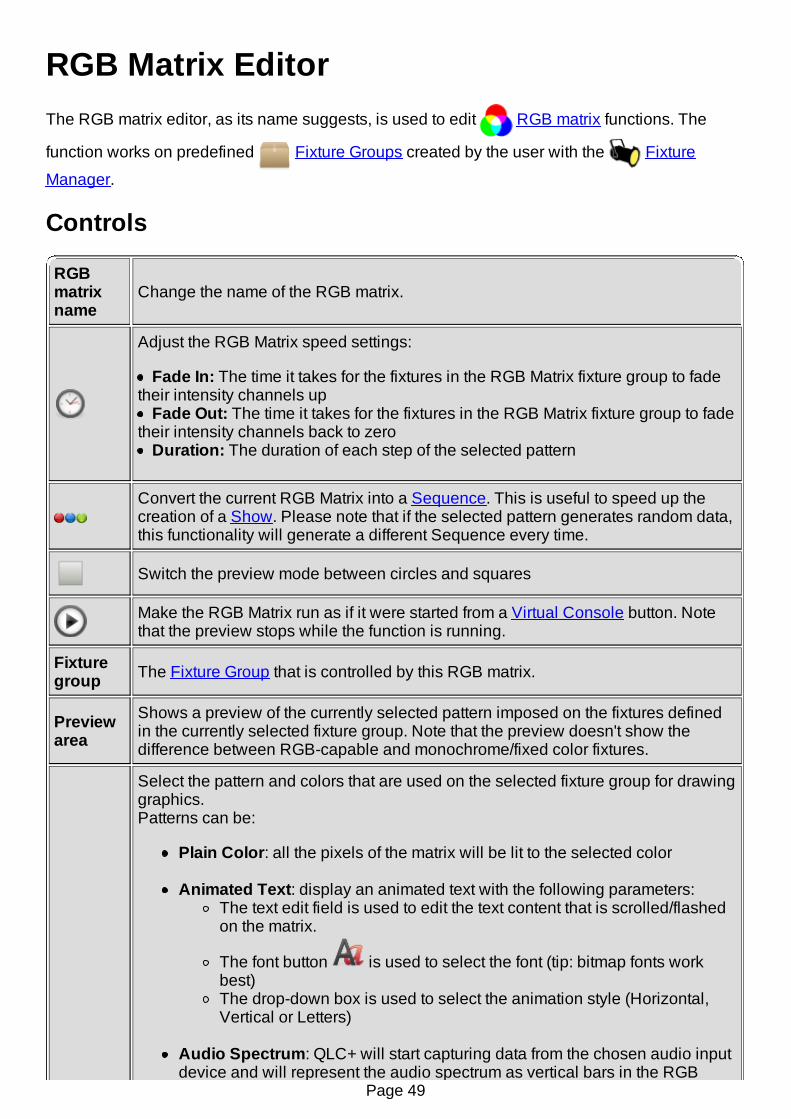
RGB Matrix EditorThe RGB matrix editor, as its name suggests, is used to edit RGB matrix functions. The
function works on predefined Fixture Groups created by the user with the Fixture
Manager.
Controls
RGBmatrixname
Change the name of the RGB matrix.
Adjust the RGB Matrix speed settings:
Fade In: The time it takes for the fixtures in the RGB Matrix fixture group to fadetheir intensity channels up
Fade Out: The time it takes for the fixtures in the RGB Matrix fixture group to fadetheir intensity channels back to zero
Duration: The duration of each step of the selected pattern
Convert the current RGB Matrix into a Sequence. This is useful to speed up thecreation of a Show. Please note that if the selected pattern generates random data,this functionality will generate a different Sequence every time.
Switch the preview mode between circles and squares
Make the RGB Matrix run as if it were started from a Virtual Console button. Notethat the preview stops while the function is running.
Fixturegroup The Fixture Group that is controlled by this RGB matrix.
Previewarea
Shows a preview of the currently selected pattern imposed on the fixtures definedin the currently selected fixture group. Note that the preview doesn't show thedifference between RGB-capable and monochrome/fixed color fixtures.
Select the pattern and colors that are used on the selected fixture group for drawinggraphics.Patterns can be:
Plain Color: all the pixels of the matrix will be lit to the selected color
Animated Text: display an animated text with the following parameters:The text edit field is used to edit the text content that is scrolled/flashedon the matrix.
The font button is used to select the font (tip: bitmap fonts workbest)The drop-down box is used to select the animation style (Horizontal,Vertical or Letters)
Audio Spectrum: QLC+ will start capturing data from the chosen audio inputdevice and will represent the audio spectrum as vertical bars in the RGB
Page 49

Pattern
Matrix with the selected start and end color.For an optimal usage of this pattern, the hold time of the Matrix must be set toa reasonably low value (e.g. .20)
Image: display an image loaded from a file, with the following parameters:The text edit field is used to edit the image filename
The image button is used to load an image from fileThe drop-down box is used to select the animation style (Static,Horizontal, Vertical or Animation)
Supported formats: PNG, XPM, JPG, GIF (for animated gifs only first frame isused).
Styles:
Static - the image is statically displayed on the matrix. If the image issmaller than the matrix, it is repeated in both directions. (Tip: for stripes,use 1-point-high images)Horizontal - the image is scrolled horizontaly. Again, image is repeatedin both directions.Vertical - same as Horizontal, but in vertical direction.Animation - play animation. Stack the frames (of width equal tomatrix's) side by side in one image. For example, when matrix is 8x8and you want to have 4 frames, make image 32x8. The image is stillrepeated vertically.
The rest of the pattern list is filled with RGB Scripts loaded when QLC+ startsup.Depending on the selected pattern, it is possible to choose a start and an endcolor. Some patterns do not allow colors at all (since they elapse themautonomously) or allow just one color.
PatternBlendMode
The blend mode is the mechanism used to mix multiple RGB Matrices running oneon top of the other.Here's a representation of how it works:
The matrix running on the bottom layer must use the default mode, to prepare aground of colors that all the above layers can use to perform blending.
Offset
Available only when Text or Image is the selected pattern.
X: Used to shift the pattern along the horizontal x-axis (negative values go tothe left, positive values go to the right)Y: Used to shift the pattern along the vertical y-axis (negative values go up,
Page 50

positive values go down)
RunOrder
Loop: Run through the steps over and over again.Single Shot: Run through the steps once and then stop.Ping Pong: Run through the steps over and over again, reversing direction atboth ends.
DirectionForward: Run through the steps from start to end; 1, 2, 3...Backward: Run through the steps from end to start; ...3, 2, 1
OtherControls
Dimmer control: When enabled, dimmer channel of include fixtures will beset to 100% when the matrix is running. Uncheck if you want independentintensity control.
Page 51

RGB Script FundamentalsUsers can write their own RGB scripts to produce custom graphics projection with the RGBMatrix function. The scripts' operation principle is to produce a number of RGB maps that eachrepresent one step in the graphics animation. The principle is basically the same as in movies:the audience observes a moving picture, which in reality is only a sequentially-played stream ofstatic images that produce an illusion of movement.
The scripts themselves are written in ECMAScript, which is also known as JavaScript. Note thatthe language is case-sensitive and as a de-facto standard follows camel case rules, so makesure you write everything correctly and pay special attention to the required API features.
Script files should be named after the script's name and must have a .js extension. Depending onplatform, the files should be placed either in the QLC+ system script directory or, preferably, theuser script directory:
Linux user dir: ~/.qlcplus/rgbscripts/Linux system dir: /usr/share/qlcplus/rgbscripts/
OSX user dir: ~/Library/Application Support/QLC+/RGBScriptsOSX system dir: /Applications/QLC+.app/Contents/Resources/RGBScripts
Windows user dir: %HOMEPATH%\QLC+\RGBScriptsWindows system dir: C:\QLC+\RGBScripts
RGB Script APIFoundationThe scripts must be self-executing, i.e. when they are evaluated, the script itself is put inside ananonymous function that executes itself and returns an object that contains the required APIfunctions:
( function() { // Anonymous function starts here var algo = new Object; return algo; // Return the script object } // Anonymous function ends here )() // Anonymous function is executed here upon evaluation
PropertiesHowever, a script with nothing more than an empty object does nothing, no matter how self-executing it might be. You must also declare some properties for the returned object so thatQLC+ knows how to use the script and to show it to the user (you). So, you need to declare thefollowing properties for the returned script object:
apiVersion: The API version that the script follows. Currently, the accepted values are '1' or'2'.apiVersion 1 allows simple scripting and easier coding, while apiVersion 2 offers advancedfeatures described below.Any other value will cause the script to be treated as invalid.name: The name of your script. This name appears in the pattern selection box in the RGBMatrix Editorauthor: The name of the person who has written the script. You.acceptColors (optional): Informs QLC+ if the script can accept a start color, an end coloror none.'acceptColors = 0' means no colors are accepted/needed. It means that the script willautonomously generate the colors information for the matrix pixels.'acceptColors = 1' means only the start color is needed by the script.'acceptColors = 2' means both start and end colors will be accepted by the script.If 'acceptColors' is not provided, QLC+ will default to value '2'.
With this in mind we add declarations for these three properties to the script:
( function() { var algo = new Object; algo.apiVersion = 2; // Can be '1' or '2' algo.name = "My cool RGB script"; algo.author = "Your name"; algo.acceptColors = 2; // Can be '0', '1' or '2' return algo; } )()
FunctionsNow we are getting to the actual business of producing data for the RGB Matrix. The current APIversion uses two functions to achieve this:
Page 52

rgbMapStepCount(width, height)rgbMap(width, height, rgb, step)
No assumptions on the calling order or argument immutability should be made, i.e. do not cachethe values from either function and assume that they are valid until the end of the world. Theparameters might change at any point (usually when the user changes the matrix size, color ordirection) thus invalidating any cached values.
rgbMapStepCount(width, height)
When QLC+ calls this function, it wants to know the number of different RGB maps returned bythe rgbMap() function, when the RGB matrix size is width times height pixels. It must alwaysreturn the same result when called with the same width and height parameters again and theresult must not change over time.
Parameters:
width: The width of the gridheight: The height of the gridReturn value: Number of steps produced by rgbMap() with the given width and heightparameters
So, now we add this support function to the script:
( function() { var algo = new Object; algo.apiVersion = 1; algo.name = "My cool RGB script"; algo.author = "Your name";
algo.rgbMapStepCount = function(width, height) { ... return number_of_steps_when_width_is_oranges_and_height_is_jabberwocky; }
return algo; } )()
rgbMap(width, height, rgb, step)
This function is the actual brains of the script. It produces two-dimensional arrays whose sizeMUST be height times width. I.e. the array returned from this function must contain height itemsand each of these items must be an array that contains width items that must be 32bit integers,representing an RGB color as understood by QRgb without alpha channel (0x00RRGGBB). Thergb parameter is an integer-representation of the color selected by user in the RGB Matrix Editor.The step parameter tells the step number requested by the RGB Matrix function and isguaranteed to be within (0, rgbMapStepCount(w, h) - 1).
Parameters:
width: The width of the gridheight: The height of the gridrgb: The color selected by userstep: Current step number to produce (between 0 and rgbMapStepCount(w, h) - 1)Return value: An array containing [height] arrays each containing [width] integers
Just like the previous function, we also add this other one to the script. Now we have a full andready template for any RGB script for your indulgence.
( function() { var algo = new Object; algo.apiVersion = 1; algo.name = "My cool RGB script"; algo.author = "Your name";
algo.rgbMapStepCount = function(width, height) { ... return number_of_steps_when_width_is_oranges_and_height_is_jabberwock; }
algo.rgbMap = function(width, height, rgb, step) { ... return a_2d_array_of_arrays; }
return algo; } )()
API version 2Page 53
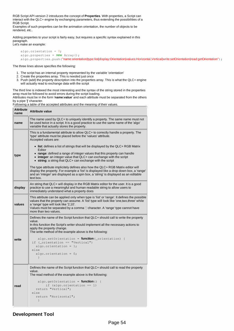
RGB Script API version 2 introduces the concept of Properties. With properties, a Script caninteract with the QLC+ engine by exchanging parameters, thus extending the possibilities of aRGB Script.Examples of such properties can be the animation orientation, the number of objects to berendered, etc..
Adding properties to your script is fairly easy, but requires a specific syntax explained in thisparagraph.Let's make an example:
algo.orientation = 0; algo.properties = new Array(); algo.properties.push("name:orientation|type:list|display:Orientation|values:Horizontal,Vertical|write:setOrientation|read:getOrientation");
The three lines above specifies the following:
1. The script has an internal property represented by the variable 'orientation'2. Create the properties array. This is needed just once3. Push (add) the property description into the properties array. This is what the QLC+ engine
will actually read to exchange data with the script
The third line is indeeed the most interesting and the syntax of the string stored in the propertiesarray must be followed to avoid errors during the script loading.Attributes must be in the form 'name:value' and each attribute must be separated from the othersby a pipe '|' character.Following a table of the accepted attributes and the meaning of their values.
Attributename Attribute value
nameThe name used by QLC+ to uniquely identify a property. The same name must notbe used twice in a script. It is a good practice to use the same name of the 'algo'variable that actually stores the property.
type
This is a fundamental attribute to allow QLC+ to correctly handle a property. The'type' attribute must be placed before the 'values' attribute.Accepted values are:
list: defines a list of strings that will be displayed by the QLC+ RGB MatrixEditorrange: defined a range of integer values that this property can handleinteger: an integer value that QLC+ can exchange with the scriptstring: a string that QLC+ can exchange with the script
The type attribute implicitely defines also how the QLC+ RGB Matrix editor willdisplay the property. For example a 'list' is displayed like a drop down box, a 'range'and an 'integer' are displayed as a spin box, a 'string' is displayed as an editabletext box.
displayAn string that QLC+ will display in the RGB Matrix editor for the user. It is a goodpractice to use a meaningful and human readable string to allow users toimmediately understand what a property does
values
This attribute can be applied only when type is 'list' or 'range'. It defines the possiblevalues that the property can assume. A 'list' type will look like 'one,two,three' whilea 'range' type will look like '2,10'.Values must be separated by a comma ',' character. A 'range' type cannot havemore than two values.
write
Defines the name of the Script function that QLC+ should call to write the propertyvalue.In this function the Script's writer should implement all the necessary actions toapply the property change.The write method of the example above is the following:
algo.setOrientation = function(_orientation) { if (_orientation == "Vertical") algo.orientation = 1; else algo.orientation = 0; }
read
Defines the name of the Script function that QLC+ should call to read the propertyvalue.The read method of the example above is the following:
algo.getOrientation = function() { if (algo.orientation == 1) return "Vertical"; else return "Horizontal"; }
Development Tool
Page 54
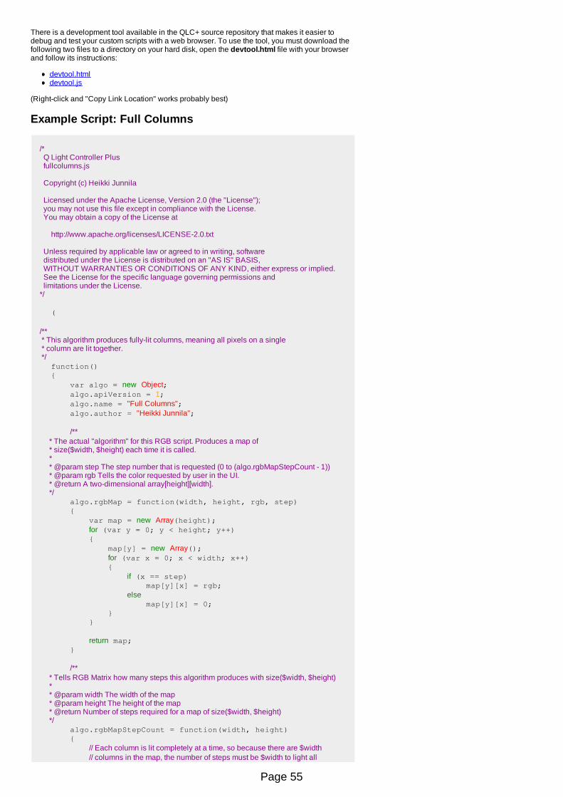
There is a development tool available in the QLC+ source repository that makes it easier todebug and test your custom scripts with a web browser. To use the tool, you must download thefollowing two files to a directory on your hard disk, open the devtool.html file with your browserand follow its instructions:
devtool.htmldevtool.js
(Right-click and "Copy Link Location" works probably best)
Example Script: Full Columns
/* Q Light Controller Plus fullcolumns.js
Copyright (c) Heikki Junnila
Licensed under the Apache License, Version 2.0 (the "License"); you may not use this file except in compliance with the License. You may obtain a copy of the License at
http://www.apache.org/licenses/LICENSE-2.0.txt
Unless required by applicable law or agreed to in writing, software distributed under the License is distributed on an "AS IS" BASIS, WITHOUT WARRANTIES OR CONDITIONS OF ANY KIND, either express or implied. See the License for the specific language governing permissions and limitations under the License. */
( /** * This algorithm produces fully-lit columns, meaning all pixels on a single * column are lit together. */ function() { var algo = new Object; algo.apiVersion = 1; algo.name = "Full Columns"; algo.author = "Heikki Junnila";
/** * The actual "algorithm" for this RGB script. Produces a map of * size($width, $height) each time it is called. * * @param step The step number that is requested (0 to (algo.rgbMapStepCount - 1)) * @param rgb Tells the color requested by user in the UI. * @return A two-dimensional array[height][width]. */ algo.rgbMap = function(width, height, rgb, step) { var map = new Array(height); for (var y = 0; y < height; y++) { map[y] = new Array(); for (var x = 0; x < width; x++) { if (x == step) map[y][x] = rgb; else map[y][x] = 0; } }
return map; }
/** * Tells RGB Matrix how many steps this algorithm produces with size($width, $height) * * @param width The width of the map * @param height The height of the map * @return Number of steps required for a map of size($width, $height) */ algo.rgbMapStepCount = function(width, height) { // Each column is lit completely at a time, so because there are $width // columns in the map, the number of steps must be $width to light all
Page 55
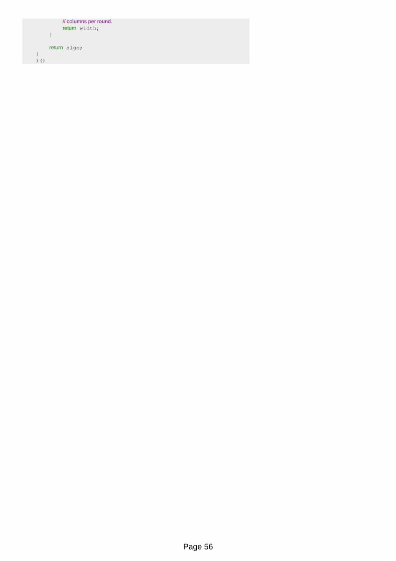
// columns per round. return width; }
return algo; } )()
Page 56

Script EditorThe Script Editor, as its name suggests, is used to edit Script functions.
It basically consists in a text editor where the user can write a script using a meta-language witha syntax described below.The script can be manually modified if you have a full understanding of the language syntax,otherwise a few helper buttons are available on the rightmost side of the editor to speed up andfacilitate the script creation/editing.Each line of a script will be executed by QLC+ in a sequential order.
Controls
Enable the output and run the Script to test its execution
Scriptname Change the name of the Script.
When clicked, this button will display a popup where you can choose the script snippetyou want to insert at the current cursor position in the editor.
Start Function: Opens the Functon Selection dialog to select a Function tobe started.This operation will automatically add a comment at the end of the line of code,with the QLC+ name of the selected Function.
Stop Function: Opens the Functon Selection dialog to select a Function tobe stopped. If at the moment of execution of this line of code the selectedFunction is not running, this instruction will have no effect.This operation will automatically add a comment at the end of the line of code,with the QLC+ name of the selected Function.
Set Fixture: Opens the Fixture Channels selection dialog, where you canchoose the channels you want to control with the Script. If multiple channels areselected, this operation will add one line of code for each selected channel. Bydefault, the DMX value generated by this opration will be 0 and has to bechanged manually with the script text editor.This operation will automatically add a comment at the end of the line of code,with the QLC+ name of the selected fixtures and channels.
System Command: Opens a file dialog to choose the externalprogram/script to run. Please note that the selected file must be executable to beaccepted. Once a file has been selected another dialog will ask to enter theprogram/script arguments. If none are required, just leave the field empty.
Wait: Opens a dialog requesting the time to be waited before the script canexecute the next instruction
Comment: Opens a dialog requesting the text of the comment to insert at thecursor position in the editor.A comment has a C language style appearance: it starts with "//" and everythinguntil the end of the line is then considered a comment
Random Number: Opens a dialog requesting the range of values where toperform a randomization of a number. The resulting code snippet will be insertedat the editor current cursor position.This can be useful to randomize DMX values set through the setfixture keyword.See below.
File Path: Open a file dialog to select a file. The absolute path and the filename will be insterted at the editor current position.If a path contains spaces, it will be writen within quotes
Cut the currently selected text in the editor for a later paste
Copy the currently selected text in the editor for a later paste
Paste a previously cut or copied text at cursor position in the editor
Undo the last performed operation on the editor
Check the Script syntax. A popup message will be displayed indicating if the Script isOK or the line numbers where syntax errors have been found.
Language syntax
The QLC+ Script meta-language is based on a keyword:value model, with some insertions of Clanguage syntax rules.Each line of code is parsed by the QLC+ engine and verified to detect the presence of syntaxerrors.Here's a table describing each keyword accepted by the Script engine and its syntax.
startfunction
Type: keywordDescription: starts a QLC+ Function with the given ID.Syntax: startfunction:functionID
functionID is an integer number of the ID assigned by QLC+ to a Function. Since IDs are not exposed to QLC+ users, in this case it is convenient to use thehelper button on the rightmost side of the editor, which also add a comment with the Function name.Eventually a user will learn the ID of a Function and therefore use it to manually add more code to the script.Example:
startfunction:2 // Green scene
stopfunction
Type: keywordDescription: stops a running QLC+ Function with the given ID.Syntax: stopfunction:functionID
functionID is an integer number of the ID assigned by QLC+ to a Function. See startfunction description.Example:
Page 57

stopfunction:0 // Blue scene
systemcommand
Type: keywordDescription: execute a program or a script at the provided absolute path with the (optional) provided arguments.Syntax: systemcommand:programPath arg:arg1 arg:arg2 ... arg:argN
programPath is the absolute path of an executable program or script. For example "/usr/bin/vlc" or "C:\Tools\myTool.exe"If the path to an executable contains spaces, it must be written between quotes.arg1 ... argN are the arguments to be used when executing programPath. If no arguments are needed, then the arg: keywords are not necessary.If an argument contans spaces it must be written between quotes.Examples:
systemcommand:/usr/bin/vlc arg:-f arg:/home/user/video.mp4 // plays my video with VLC in fullscreen systemcommand:"C:\Program Files\Tools\My Tool.exe" arg:"D:\My Files\My file.txt"
setfixture
Type: keywordDescription: sets a QLC+ Fixture channel to the provided DMX value.Syntax: setfixture:fixtureID ch:channelIndex val:DMXValue
fixtureID is an integer number of the ID assigned by QLC+ to a Function. Since IDs are not exposed to QLC+ users, in this case it is convenient to use thehelper button on the rightmost side of the editor, which also add a comment with the fixture and channel name.Eventually a user will learn the ID of a fixture and the index of a channel and therefore use them to manually add more code to the script.channelIndex is an integer number representing the fixture channel number. Channels indices here start from 0.DMXValue is the actual DMX value to be set to the specified fixture channel. It ranges from 0 to 255Example:
setfixture:0 ch:1 val:135 // Generic RGB, Red. Sets the red channel of a Generic RGB fixture to DMX value 135
wait
Type: keywordDescription: wait for the provided amount of time before executing the next line of code.Note that a wait time can be randomized too, following the random syntax described below.Syntax: wait:time
time can be either an integer number of milliseconds or a string representing the wait time in the QLC+ way: **h**m**s.**Examples:
wait:1800 // Waits for 1 second and 800 milliseconds wait:03s.20 // Waits for 3 seconds and 200 milliseconds
comments
Type: Helper macroDescription: comments can be inserted at any position in the script code and they do not affect the script execution. They are normally used to give ameaning to a line of code.QLC+ Scripts comment follow the C Language style rule of the "//" syntax. Basically everything written after "//" will be considered a comment until the endof the line of code.So pay a particular attention to not writing meaningful code after a "//" and expect it to be run, cause it won't.Comments can be added at the end of a Script line of code or they can take a whole line, for example to describe an entire block of code.
random
Type: Helper macroDescription: generates a random integer number between the provided minimum and maximum valuesSyntax: random(min,max)
min is the minimum value the randomization can reach. It can be either an integer number or a time stringmax is the maximum value the randomization can reach. It can be either an integer number or a time stringExamples:
wait:random(02s.00,05s.00) // Waits a random time between 2 and 5 seconds
// set channel 3 of fixture with ID:1 to a random DMX value between 20 and 235 setfixture:1 ch:2 val:random(20,235)
Page 58

Audio EditorThe audio editor, as its name suggests, is used to edit Audio functions.
It offers basic controls and shows information about the attached audio file.
Controls
Start/stop the audio file playback. If the file doesn't exist, this button will have noeffect
Audioname
Change the name of the Audio function. By default this is set with the file name,until it is manually changed.
File name Displays the absolute path of the current file attached to this Audio function. Thesource file can be changed by clicking on the "..." button on the right side.
Duration Displays the audio file duration in the typical QLC+ way. For example: 04m14s.22.
Channels Displays the number of channels detected from the attached audio file. 2 meansstereo and 1 means mono.
SampleRate
Displays the sample frequency of the attached audio file, in Hertz. For example:44100Hz, 48000Hz, etc
BitrateDisplays the bitrate of the attached audio file, in Kb/s. Audio files can have aconstant bitrate (CBR) or a variable bitrate (VBR). In the latter case, an averagebitrate is displayed.
Loop Loop audio playback until explicitly stopped.
Show/Hide the Speed Dial widget, used to facilitate the audio fade in/outparameters tuning
Fade InText box to enter a fade in time for the audio playback. Times can be entered in aQLC+ way (e.g. 3s.55) or in seconds (e.g. entering '2' and pressing Enter will turninto 02s.00)
Fade Out Text box to enter a fade out time for the audio playback. Times can be entered likein the Fade In box
AudioDevice
Select a specific audio output device to be used to play the attached audio file.This list is the same you can find in the Audio Input/Output panel
Page 59

Video EditorThe video editor, as its name suggests, is used to edit Video functions.
Controls
Start/stop the video playback. If the file doesn't exist or an invalid URL has beenentered, this button will have no effect
Videoname
Change the name of the Video function. By default this is set with the file name,until it is manually changed.
File name
If the attached file is local, displays the absolute path of the video file. A localsource file can be changed by clicking on the "..." button on the right side.
It is also possible to stream a video from the network. Just click on the button and enter a valid HTTP URL.
Duration Displays the video file duration in the typical QLC+ way. For example:04m14s.22.
Resolution
Displays the resolution in pixels detected on the attached video file.Note: since QLC+ relies on the Qt libraries to play video sources, there is aknown issue for which Qt is not able to detect the size (and codecs) of videos inWindows and Mac OSX.Basically a size of "0x0" will be displayed. The fullscreen video playback will beOK though.On detection failure, a default size of 640x480 pixels is internally set to allow thewindowed mode to work.Hopefully this will be fixed by the Qt team in the future.
Videocodec
Displays the codec used to compress the video stream into the attached videofile.
Audiocodec
Displays the codec used to compress the audio stream into the attached videofile.
ScreenAllows to select the output screen where the video should be playback. This willnormally displays just one choice unless multiple video outputs (monitors,projectors) are connected to the system
VideoOutput
Allows to choose how the attached video should be displayed. Possible optionsare
Windowed: a window with the original size of the video will be displayedon the selected output screen.Fullscreen: The video will use the whole screen size, without showing anywindow decoration (title bar, etc)
Playbackmode
Allows to choose how the attached video should be played. Possible options are
Single shot: The video will be played just onceLoop: The video playback will be restarted from the beginning whenreaching the end. The loop mode will continue indefinitely until the Videofunction is stopped.
Page 60

Page 61

Function WizardThe Function Wizard's purpose is to help users create some common functions for a quick start.
Controls
FixtureList
List of fixtures that will be included in the functions created with the wizard. You cansee each fixture's capabilities for Color-, Gobo- and Shutter- type scenes in theSupported capabilities column.
Include Fixtures to the functions that will be created with the wizard.
Remove the selected fixtures from the function to be created.
Scenes
Colors: Create scenes for changing the color simultaneously on all currentlyincluded fixtures. For this to work, the fixtures must have at least one colorchannel that controls a fixed-color wheel.Gobos: Create scenes for changing the gobo simultaneously on all currentlyincluded fixtures. For this to work, the fixtures must have at least one gobochannel.Shutter: Create scenes for changing the shutter position simultaneously on allcurrently included fixtures. For this to work, the fixtures must have at least oneshutter channel.
Page 62
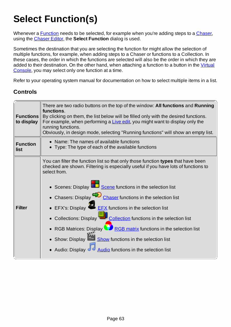
Select Function(s)Whenever a Function needs to be selected, for example when you're adding steps to a Chaser,using the Chaser Editor, the Select Function dialog is used.
Sometimes the destination that you are selecting the function for might allow the selection ofmultiple functions, for example, when adding steps to a Chaser or functions to a Collection. Inthese cases, the order in which the functions are selected will also be the order in which they areadded to their destination. On the other hand, when attaching a function to a button in the VirtualConsole, you may select only one function at a time.
Refer to your operating system manual for documentation on how to select multiple items in a list.
Controls
Functionsto display
There are two radio buttons on the top of the window: All functions and Runningfunctions.By clicking on them, the list below will be filled only with the desired functions.For example, when performing a Live edit, you might want to display only therunning functions.Obviously, in design mode, selecting "Running functions" will show an empty list.
Functionlist
Name: The names of available functionsType: The type of each of the available functions
Filter
You can filter the function list so that only those function types that have beenchecked are shown. Filtering is especially useful if you have lots of functions toselect from.
Scenes: Display Scene functions in the selection list
Chasers: Display Chaser functions in the selection list
EFX's: Display EFX functions in the selection list
Collections: Display Collection functions in the selection list
RGB Matrices: Display RGB matrix functions in the selection list
Show: Display Show functions in the selection list
Audio: Display Audio functions in the selection list
Page 63
Select Fixture(s)Whenever a Fixture needs to be selected, for example when adding fixtures to a Scene function,the Select Fixture(s) dialog is used.
The dialog is very straightforward; there is only a list of fixtures that you can select from. In somecases you are allowed to select multiple fixtures, for example, when adding fixtures to a Scene oran EFX. In these cases, the order in which the fixtures are selected will also be the order in whichthey are added to their destination.
Refer to your operating system manual for documentation on how to select multiple items in a list.
Page 64

Show ManagerThe Show Manager has been introduced in QLC+ starting from version 4.0.0, after forking theoriginal QLC code on November 5th, 2012.
This feature is meant to give users the possibility of setting up a time driven show in a friendlyand completely graphical way.The graphic interface shows a multitrack view, typical of audio sequencers or video editingsoftwares, and with it users are allowed to place QLC+ Functions at the desired place and time inthe view.Show Manager gives a lot of flexibility during a Show creation thanks to its visual-orientedapproach. Once understood the basic elements, it is very easy to create, move or edit the existingfunctions and improve a Show by adding new tracks to it.
Typical use cases of Shows are those gigs where a band plays songs following a metronomeand the light show has always to be the same, following the music.Another case are visual entertainment shows, where dancers or singers follow some music andlights create the atmosphere at the right time.
The Show Manager drives users to make large use of the Sequence function. Here's theexplanation of the difference between a Chaser and a Sequence.
Sequences vs ChasersEven if the Sequence and the Chaser functions have some common ground, they're not the samething.If not done yet, you are invited to read once again their definitions in the Basic Concepts &Glossary page of this documentation.The main differences are:
Steps: The steps of a Chaser can represent any QLC+ Function, while the steps of aSequence represents different values of the same Scene.In other words, a Chaser is an independent function, while a Sequence can exist only ontop of a Scene.The reason for this is, as mentioned before, the visual approach of the Show Manager. If atrack of a Show is the graphical representation of a Scene, then it's more intuitive to thinkthat each Sequence created on that track is a function controlling the values of that Scene.Order: Chasers can be reproduced in any order (Forward, Backward, Ping-Pong, Random)while in the Show Manager, Sequences are always reproduced from the beginning to theend (Forward). Again, this is related to the visual aspect of the Show Manager, where theplayback has a natural time forward direction.On the other hand, Sequences created with the Function Manager can have the same orderproperties of Chasers.Editing: The editing approach between Sequences and Chaser is different too.Normally the workflow of a Chaser is: create a Function, then add it to the Chaser as a step.The workflow of a Sequence is: create a Scene, create a Sequence on top of it, add stepsto it.The Sequence approach might be very effective when you design a light show if you canpre-determine which fixtures you're going to use. Another major advantage of Sequenceediting is that when you create a new step, the values of the previous step are copied in thenew one. So the user is simply required to adjust the differences between them.If you are going to create 500 steps and they're all different, then Sequences and Chaserswill take almost the same time to be created.Synchronization: another major advantage of using Sequences in a Show is that a Show
Page 65

can easily be extended (or reduced) while with a Chaser you will have a hard time tosynchronize the new functions to the existing ones.An example. Let's say your project controls 50 fixtures that are a mixture of moving heads,PARs and scanners. At some point you buy a couple of lasers and you want them tobecome active in existing scenes at precise moments in time. The Show Manager allowsyou to do that in a few minutes ! You just need to add the 2 new fixtures to the project, add atrack to the Shows affected by the change and create a few Sequences to control thelasers.The Show Manager resume functionality will also save you a lot of time when testing thenew changes.With Chasers you'd probably have to deal with complex Collections and review the timingsof a few steps before finding the right combination.
Show Manager toolbar controls
CTRL+HCreate a new Show. A Show is represented as a multitrackworkspace where tracks, sequences and audio elements canbe added
Shows list This drop down box lists the currently created Shows. Clickingon a Show will display it.
CTRL+N
Create a new track or add existing functions to the Show. Whenclicking on this button a window is displayed, allowing you toperform the following operations:
Create a new track: This creates a new empty track thatwill serve as a container for Sequences and Audiofunctions.Import an existing Scene. This will create a new track anda 10 seconds Sequence with one single steprepresenting the selected Scene.Import an existing Sequence: this operation scans theexisting tracks and if it finds a track already bound to theSequence's bound Scene, then add the Sequence to thattrack at the cursor position.If no compatible track is found, a new track will be createdand bound to the Sequence's bound Scene.Import an existing Chaser: add a Chaser function at thecursor position on the selected track. If no track isavailable, it will create a new one.Import an existing Audio: add an Audio function at thecursor position on the selected track. If no track isavailable, it will create a new one.Import an existing EFX: add an EFX function at the cursorposition on the selected track. If no track is available, itwill create a new one.Import an existing RGB Matrix: add a RGB Matrix functionat the cursor position on the selected track. If no track isavailable, it will create a new one.
A Show can have a virtually infinite number of tracks.
CTRL+E Create a new Sequence item and bind it to the selected track.
Create a new Audio item. An audio item simply represents anPage 66
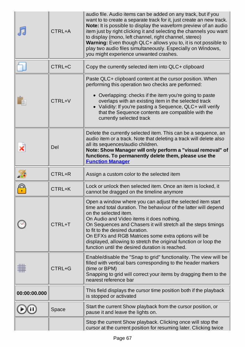
CTRL+A
audio file. Audio items can be added on any track, but if youwant to to create a separate track for it, just create an new track.Note: It is possible to display the waveform preview of an audioitem just by right clicking it and selecting the channels you wantto display (mono, left channel, right channel, stereo)Warning: Even though QLC+ allows you to, it is not possible toplay two audio files simultaneously. Especially on Windows,you might experience unwanted crashes.
CTRL+C Copy the currently selected item into QLC+ clipboard
CTRL+V
Paste QLC+ clipboard content at the cursor position. Whenperforming this operation two checks are performed:
Overlapping: checks if the item you're going to pasteoverlaps with an existing item in the selected trackValidity: If you're pasting a Sequence, QLC+ will verifythat the Sequence contents are compatible with thecurrently selected track
Del
Delete the currently selected item. This can be a sequence, anaudio item or a track. Note that deleting a track will delete alsoall its sequences/audio children.Note: Show Manager will only perform a "visual removal" offunctions. To permanently delete them, please use theFunction Manager
CTRL+R Assign a custom color to the selected item
CTRL+K Lock or unlock then selected item. Once an item is locked, itcannot be dragged on the timeline anymore
CTRL+T
Open a window where you can adjust the selected item starttime and total duration. The behaviour of the latter will dependon the selected item.On Audio and Video items it does nothing.On Sequences and Chasers it will stretch all the steps timingsto fit to the desired duration.On EFXs and RGB Matrices some extra options will bedisplayed, allowing to stretch the original function or loop thefunction until the desired duration is reached.
CTRL+G
Enable/disable the "Snap to grid" functionality. The view will befilled with vertical bars corresponding to the header markers(time or BPM)Snapping to grid will correct your items by dragging them to thenearest reference bar
00:00:00.000 This field displays the cursor time position both if the playbackis stopped or activated
Space Start the current Show playback from the cursor position, orpause it and leave the lights on.
Stop the current Show playback. Clicking once will stop thecursor at the current position for resuming later. Clicking twice
Page 67
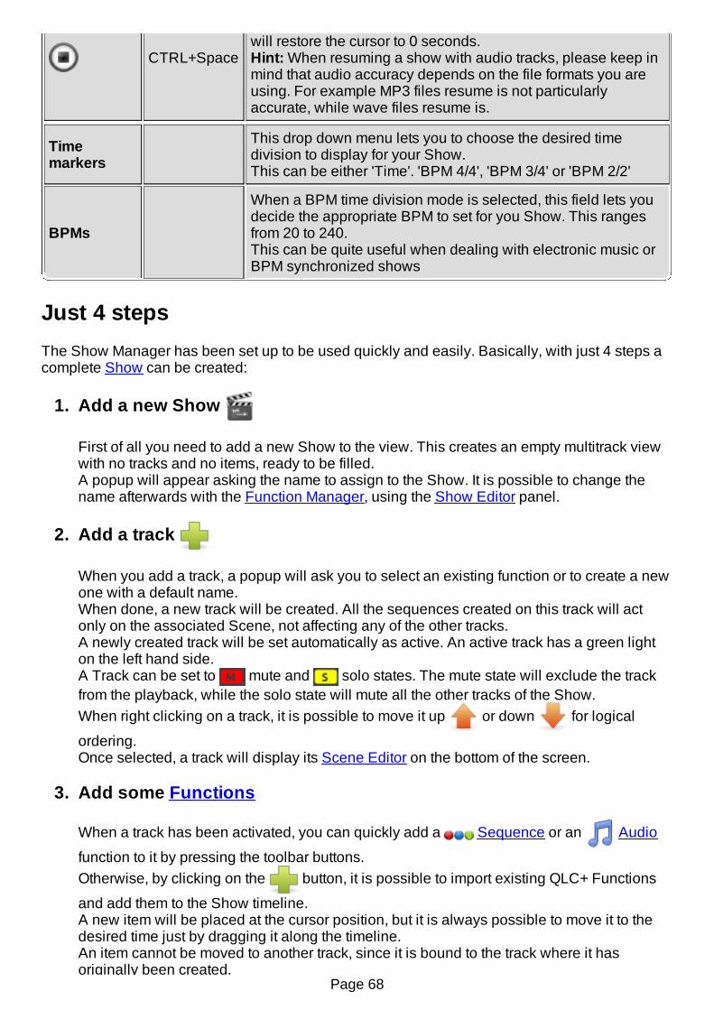
CTRL+Spacewill restore the cursor to 0 seconds.Hint: When resuming a show with audio tracks, please keep inmind that audio accuracy depends on the file formats you areusing. For example MP3 files resume is not particularlyaccurate, while wave files resume is.
Timemarkers
This drop down menu lets you to choose the desired timedivision to display for your Show.This can be either 'Time'. 'BPM 4/4', 'BPM 3/4' or 'BPM 2/2'
BPMs
When a BPM time division mode is selected, this field lets youdecide the appropriate BPM to set for you Show. This rangesfrom 20 to 240.This can be quite useful when dealing with electronic music orBPM synchronized shows
Just 4 stepsThe Show Manager has been set up to be used quickly and easily. Basically, with just 4 steps acomplete Show can be created:
1. Add a new Show
First of all you need to add a new Show to the view. This creates an empty multitrack viewwith no tracks and no items, ready to be filled.A popup will appear asking the name to assign to the Show. It is possible to change thename afterwards with the Function Manager, using the Show Editor panel.
2. Add a track
When you add a track, a popup will ask you to select an existing function or to create a newone with a default name.When done, a new track will be created. All the sequences created on this track will actonly on the associated Scene, not affecting any of the other tracks.A newly created track will be set automatically as active. An active track has a green lighton the left hand side.A Track can be set to mute and solo states. The mute state will exclude the trackfrom the playback, while the solo state will mute all the other tracks of the Show.When right clicking on a track, it is possible to move it up or down for logical
ordering.Once selected, a track will display its Scene Editor on the bottom of the screen.
3. Add some Functions
When a track has been activated, you can quickly add a Sequence or an Audio
function to it by pressing the toolbar buttons.Otherwise, by clicking on the button, it is possible to import existing QLC+ Functions
and add them to the Show timeline.A new item will be placed at the cursor position, but it is always possible to move it to thedesired time just by dragging it along the timeline.An item cannot be moved to another track, since it is bound to the track where it hasoriginally been created.
Page 68

originally been created.An item can be copied , pasted or deleted with the toolbar icons. The pasted
item will be placed at the current cursor position.The item background color can be changed with the toolbar icon . The assigned color
will be saved in your project file.Once selected, an item will display its specific Function Editor on the right hand side of thescreen. When right clicking an item a contextual menu will be displayed, showing thefollowing options:
Preview: This option is available only on audio items. It will display the waveformpreview for right, left or stereo channels when availableAlign to cursor: This option will move the selected item to the cursor position
Lock/Unlock: Once an item is locked, it cannot be dragged on the timeline
anymoreFollow step 4 to understand how to fill a Sequence
4. Edit your Functions
Once an item has been created, it is now the time to edit it.Please note that the difference between a Chaser and a Sequence is that a Sequence isbound to the Track (so the Scene) where it has been created. So, when adding a step,QLC+ will not ask to select a particular function, but will always use the channels of thesame Scene.When editing a Function, you will see the item changing on the multitrack view, giving animmediate feedback for aligning to other items or particular points in time.Fade In and Fade Out times will be displayed as diagonal lines over the items on themultitrack view, while different steps/loops will be divided by vertical lines.
To increase the complexity of the Show, more Functions can be added. Just repeat the abovesteps depending on your needs.
And finally...play ! When a complete show has finally been created, it can be played just by clicking on the Playicon.Playback always starts from the current cursor postion. The cursor position can be changed byclicking on the time line.
Page 69

Virtual ConsoleThe purpose of the Virtual Console is to act as a blank canvas on which the user can create alighting desk layout of his choice. Users can place various GUI (Graphical User Interface)elements, called widgets, onto the console surface:
Buttons for starting and stopping functionsSliders for adjusting channel values or function intensitySpeed dials for adjusting function speedsXY Pads for manually moving intelligent light beamsCue lists for theatrical performance purposesFrames for grouping various widgets togetherSolo Frames for keeping only one button/function active at a timeLabels to act as static information banners for other widgets
The topmost part of the Virtual Console is dedicated to a tool bar that provides quick access tothe most common actions: adding new widgets, copying them to/from the clipboard, configuringthe widgets and, in case of emergencies, a panic button for stopping all currently runningfunctions.
Each Virtual Console widget's style can be configured (to some extent). Widgets can be movedanywhere and resized to any size on the Virtual Console canvas. See the article on VirtualConsole Widget Styling & Placement.
Tool Bar Controls
Add a new Button to the currently selected frame.
Add a new Button Matrix to the currently selected frame, using the Add Button Matrixdialog.
Add a new Slider to the currently selected frame.
Add a new Slider Matrix to the currently selected frame.
Add a new Animation to the currently selected frame.
Add a new Knob to the currently selected frame. This is a convenient shortcut for addinga slider widget using the knob style.
Add a new Speed Dial to the currently selected frame.
Add a new XY Pad to the currently selected frame.
Add a new Cue List to the currently selected frame.
Add a new Frame to the currently selected frame.
Add a new Solo Frame to the currently selected frame.
Page 70

Add a new Label to the currently selected frame.
Add a new Audio triggers widget to the currently selected frame.
Add a new Clock widget to the currently selected frame. This widget can be used for 3purposes: System clock, Stopwatch and Countdown.In the last two cases and when QLC+ is in operate mode, clicking with the mouse leftbutton will pause the counter, while clicking with the mouse right button will reset thecounter to the initial value.When in system clock mode, it is possible to schedule when to start a QLC+ functionduring the time of day.
Cut the currently selected widget(s) to the clipboard. Note that the widget(s) will onlydisappear when pasted into the new location.
Copy the currently selected widget(s) to the clipboard.
Paste the widget(s) in clipboard to the currently selected frame.
Destroy the currently selected widget(s) completely. If a frame has been selected, thisdestroys everything inside it, including other frames.
Configure the currently selected widget using its own configuration dialog.
Rename the currently selected widget(s).
Bring the selected widget to front.
Send the selected widget to back.
Change the background color of the selected widget.
Set a background picture for the selected widget.
Change the font color of the selected widget.
Set the font properties of the selected widget.
Configure the Virtual Console properties such as the size workspace, the widgets'default properties and the Grand Master slider properties.
Stop all currently running functions.
Page 71

Virtual Console FrameA Frame is a container that can hold a variety of widgets, including other frames, inside. In fact,the whole Virtual Console is already your bottom-most frame. Also, if you apply some stylingattributes to a frame, all of its children (which have not had their own non-default style settingsapplied) also inherit their parent's style properties.
Configuration
Frames can be configured with the properties button found in the toolbar or by doubleclicking the frame itself.
Other than the standard styling & placement options, Frames have the following additionaloptions, divided into 2 tabs:
Appearance tab
Frame name: Allow you to assign an arbitrary label to the Frame. This will be displayedonly when the "Show header" option is enabled (see below).Accept child widgets: Allow you to add widgets to the Frame.Allow resizing: Allow the Frame height and width to be changed.Show header: Display the frame header. By default it will display 3 elements: Anexpand/collapse button, the frame name and a enable/disable button. Some further optionalcontrols are displayed when the Frame is in multipage mode. See next paragraph.
Pages tab
Virtual Console Frames can be turned into multi-page widgets, useful when dealing with a lot ofwidgets or controllers supporting pages.The multi-page functionality is disabled by default, but can be enabled in this tab.Following the options to configure this functionality:
Enable: This check box enables/disables the multi-page functionality. When enabled, VCframes will display additional controls in the header bar (if the header bar is also enabled).These are: Previous page button, page name and next page button.Number of pages: With this counter it is possible to determine the number of pages theframe is going to handle.Clone first page widgets: When checked, QLC+ will clone the widgets of the frame's firstpage into all the other new pages defined by the "Number of pages" field. This is a veryuseful option to speed up the mapping of an external controller where all the pages havethe same widgets.External input - Previous page: You can set an external input signal or a keyboardcombination here which will cause the previous page of the frame to be displayed.External input - Next page: You can set an external input signal or a keyboardcombination here which will cause the previous page of the frame to be displayed.Page shortcuts: in the bottom section of the pages tab, it is possible to assign to eachpage a custom name, an external input signal or a keyboard combination.In this way a page can be accessed directly without going through the intermediate pages.
Header ControlsBy default a Frame is displayed with a header. Following a brief description of the default and
Page 72
optional controls that can be used either in Operate or Design mode.
Expand/Collapse button: when clicked, the Frame size will be dramaticaly reduced,
to save space on your Virtual Console. The collapsed state is saved in your project.Frame name: a label displaying the Frame name
Enable/Disable button: when clicked, the Frame will go into a disable state. All the
widgets inside the Frame will not respond anymore to input controls.This is useful, for example, to use the same input controls on widgets of different frames.For example if you bound the key "G" to a button in Frame A and also to a button on FrameB, you can enable one Frame at a time to use your key binding univocally.
Page Multipage controls (Optional): when a Frame is configured in multipage
mode, some extra buttons will be displayed on the header, allowing you to switch betweenthe Frame pages and to keep track of the current page you're in.
Page 73
Virtual Console Solo FrameA Solo Frame is almost exactly the same kind of a container as a normal Frame in that can holdvarious widgets and other frames inside. However, the difference with Solo Frame is that it treatsany Buttons inside it differently by allowing only one button to be enabled at a time. For example,consider you have Button A and Button B inside a Solo Frame with Button A currentlyenabled. Next, you click button Button B which automatically results in Button A beingreleased, leaving now only Button B enabled.
Configuration
Solo Frames can be configured with the properties button found in the toolbar or by doubleclicking the solo frame itself.
Other than the standard styling & placement options, Solo Frames have every frame additionaloptions:
Frame name: Allow you to assign an arbitrary label to the Solo Frame. This will bedisplayed only when the "Show header" option is enabled (see below).Accept child widgets: Allows you to add widgets to the Solo Frame.Allow resizing: Allow the Solo Frame height and width to be changed.Show header: Display a useful header composed of a button and a label. The buttonallows you to expand/collapse the Solo Frame, which can save a lot of Virtual Consolespace. The label will display the name of the Frame.
And one other specific option:
Mix sliders in playback mode: When this option is enabled, the sliders in playback modeare allowed to be enabled at the same time. When moving a slider up, instead of instantlycancelling the other running sliders, it will fade them out at the same speed you are fading itup.
Page 74

Virtual Console ButtonA Button is the simplest and at the same time the most powerful widget in QLC+; with it, you canstart, stop and flash your functions.
Configuration
Buttons can be configured with the properties button found in the toolbar or by doubleclicking the button itself.
Button labelSet the friendly name of the button. The name appears on the button in VirtualConsole. NOTE: If you set an icon to a button with the Edit -> Icon -> Choosemenu, the icon will override this label.
Function
Shows you the name of the Function that is currently assigned to the button.
Attach a function to the button
Detach the current function from the button
Attributes
Shows you the list of attributes of the assigned function that can be adjusted.Attributes can be controlled by right clicking on the button when in OperateMode.A popup will display a number of sliders corresponding to the number ofavailable attributes.If the assigned function is a Show, attributes correspond to the Show tracks, soyou can adjust the intensity (or volume) of a whole track with just one click.
Externalinput
You can attach an external input channel from an input device (like a sliderboard) to buttons so that you don't always have to use the mouse, touch screenor keyboard to access the buttons.
Input universe: The input universe that you wish to provide input data tothe button.Input channel: The individual input channel within the selected inputuniverse that you wish to use for controlling the button.Auto Detect: When toggled, you can just press a button on your externalinput hardware and it will be automatically assigned to the button. Thelatest combination is shown in the text boxes when QLC+ receives inputdata. If you don't see anything in the boxes, your input connection mighthave a problem that you need to fix first.Choose...: Shows the Select Input Channel dialog that you can use toselect an input channel manually.
Keycombination
You can attach a keyboard key (or key combination) to the button, which thenacts as if you clicked the button directly with your mouse.
Attach a keyboard key (or key combination) to the button
Detach the current key combination from the button
Toggle function on/off: When you click the button, the attached function isstarted. When you click the button a second time, the function is stopped,
Page 75
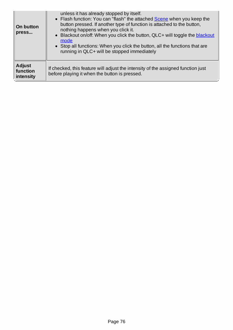
On buttonpress...
unless it has already stopped by itself.Flash function: You can "flash" the attached Scene when you keep thebutton pressed. If another type of function is attached to the button,nothing happens when you click it.Blackout on/off: When you click the button, QLC+ will toggle the blackoutmodeStop all functions: When you click the button, all the functions that arerunning in QLC+ will be stopped immediately
Adjustfunctionintensity
If checked, this feature will adjust the intensity of the assigned function justbefore playing it when the button is pressed.
Page 76
Virtual Console Button MatrixA Button Matrix is basically just a way for quickly creating multiple Buttons at the same timeinside a common container Frame.
When creating a new button matrix, you can assign functions to each of the buttons quite quicklywith the Add Button Matrix dialog.
Configuration
Refer to Frame and Button on how to configure them.
Page 77

Virtual Console SliderSliders are used for two distinct purposes: Fixture channel level setting and Function playbackand intensity adjustment. Any slider can operate on either of these modes and each mode has itsown configuration options.
Configuration
Sliders can be configured with the properties button found in the toolbar or by doubleclicking the slider itself.
Configuration - General Tab
The General tab holds all of the slider's properties that are shared between the slider's twomodes.
Slider name Change the slider's name.
Widgetappearance
A slider can be displayed as a vertical fader or as a knob . The
appearance can be changed on the fly.
Valuedisplaystyle
Actual: Display actual DMX (0-255) valuesPercentage: Display percentage values (0-100%)
Slidermovement
Normal: Values increase towards the top and decrease towards thebottom of the slider.Inverted: Flip the slider upside down so that values increase towards thebottom and decrease towards the top.
Externalinput
You can attach an external input channel from an input device (like a sliderboard) to sliders so that you don't always have to use the mouse or touch screento move sliders.
Input universe: The input universe from which you wish to get input datafor the slider.Input channel: The individual input channel within the selected inputuniverse that you wish to use for controlling the slider.Auto Detect: When toggled, you can just move/press a button/slider/knobon your external input hardware and it will be automatically assigned tothe slider. The latest combination is shown on the text boxes when QLC+receives input data. If you don't see anything in the boxes, your inputconnection might have a problem that you need to fix first.Choose...: Shows the Select Input Channel dialog that you can use toselect an input channel manually.
Configuration - Level Tab
If the slider is not currently in Level mode, all you see is a button telling you to click it to switch theslider to Level mode. After you click it, the Level mode properties will be shown.
Page 78

ValueRange
Low limit: Set the lowest DMX value that can be set by the slider.High limit: Set the highest DMX value that can be set by the slider.tFrom capability: You can limit the slider's level value range to a certaincapability range within a fixture's channel. When you have any channelvalue range selected from the fixture list (for example "Dimmer Control 006- 128") and you click this button, the low and high limit of this slider aretaken automatically from that capability and are set to 6 and 128,respectively.
Fixture listYou can select individual channels from this list that contains all channels fromall of your fixtures. Those channels that you have placed the tick mark besidewill be controlled by this slider.
All Clicking this button will select ALL channels from ALL fixtures.
None Clicking this button will clear ALL channel selections from ALL fixtures.
InvertInvert the current selection. If you have channels 1, 3 and 5 selected from allfixtures, clicking this button will de-select channels 1, 3 and 5 and instead selectchannels 2, 4 and 6 from those fixtures.
By group...
If you wish to control a specific channel group from ALL fixtures, you can clickthis button and select the channel group to control. Accepting the dialog willselect ALL channels that belong to the selected channel group from ALL fixtures.This is particularly useful if you wish to have common control over, for example,all of your scanners' intensity channels.
Click & Go
Click & Go is a QLC+ technology which allows you to quickly access fixturesfunctionalities in a completely visual way. When Click & Go is enabled, a buttonwill appear at the bottom of the slider and with just 2 clicks you will reach thedesired result.The supported modes are:
None: Click & Go disabled. No button will be displayed.Color: Single color selection. A gradient of the color controlled by the sliderwill be displayed, allowing you to jump to the desired color visually.RGB: RGB color selection. A RGB Color picker will be displayed, allowingyou to pick any color from black to white. 16 preset colors are displayed onthe left side for convenience. When selecting a color, the slider value willbe placed half way (128). Moving it downward will fade towards black,while moving it upward will fade towards white.Gobo/Effect: Gobo/Macro selection. A grid view of the fixture definedmacros will be displayed and you will be able to choose a macro from itscolor, its gobo or its name. When the mouse is over a macro cell, a blue barwill appear, allowing you to choose an intermediate value within the samemacro. This is useful for functionalities like Gobo rotation speed.
Monitor theselectedchannelsand updatethe sliderlevel
(EXPERIMENTAL) By enabled this option, the slider will watch the DMXchannels changes and if they assume all the same level, the slider will updateaccordingly for an immediate visual feedback.When activating this option, a reset button and an additional level bar will bedisplayed in the slider layout.If you interact with the slider while it is monitoring some DMX channels, it willswitch into an override state, similar to what happens in Simple Desk. The resetbutton background will turn to red, indicating that the override is in place, and theright side level bar will continue to indicate the monitoring level.When pressing the reset button from an override state, the slider will go back to
Page 79

the current monitoring level.It is possible to associate and external control to the override reset button.
Configuration - Playback Tab
If the slider is not currently in Playback mode, all you see is a button telling you to click it toswitch to Playback mode. After you click it, the Playback mode properties will be shown.
When the slider is in playback mode, the slider acts like a combined button and slider. You canstart a function AND simultaneously control the function's intensity with the slider. When theslider is at zero, the function is stopped but any value above zero will start the function (unless ithas already been started) and simultaneously adjust the function's intensity (if applicable).
A slider in Playback mode will ignore the attached Function fade in and fade out times, so fadetransitions will have to be performed manually.If you need fade in/out automations together with the control of the Function intensity, then theusage of a Virtual Console Button in combination with a Slider in Submaster mode is what
you're looking for.
Function Displays the function that is currently attached to the slider.
Attach a function to the slider.
Detach the currently attached function.
Configuration - Submaster Tab
If the slider is not currently in Submaster mode, all you see is a button telling you to click it toswitch to Submaster mode. After you click it, the slider will be set to work as a submaster.
When a slider is set to Submaster mode, it will control the intensity of every other widget in thesame frame (please keep in mind that the main Virtual Console area is a frame too !)The intensity of a widget depends on the type of widget itself and which functionality it controls. Asubmaster will control the intensity of any QLC+ "light emitting" functionality, either a function orsingle channel levels.For example a submaster can control the intensity of a function attached to a button or thechannel levels associated to a slider in level mode.Every widget is controlled by a submaster even if the widget's functionality is not active yet. Forexample if a submaster is set to 50%, a button pressed afterward will start its associated functionwith 50% of intensity.
Page 80
Virtual Console Slider MatrixA Slider Matrix is basically just a way for quickly creating multiple Sliders at the same time insidea common container Frame.
Configuration
Refer to Frame and Slider for how to configure them.
Page 81

Virtual Console AnimationAn Animation widget is a complete tool to operate with the RGB Matrices of your project.It displays several graphical elements to fully control a matrix during live shows.Most importantly, it allows you to define a number of so called "custom controls" to quickly recallpresets, colors and properties and apply them immediately to a running matrix.
Introduction
When clicking on the icon, an Animation widget will be added to your Virtual Console.By default, the widget will display 4 elements:
On the leftmost side, a slider to control the playback and the intensity of a RGB Matrix.The slider movement can be associated to an external controller input line.It behaves exactly like a Virtual Console Slider in playback mode.On the top right side, two Click & Go buttons to set the matrix start and end color. Whenclicking on them during the Operate Mode, a color picker menu will be displayed.Below the two buttons, a drop down menu to select the desired Matrix animation or preset.
The space below the animation menu, is reserved for Custom Controls. They can be defined inthe widget configuration window and each of them will be displayed as a single button.Each custom control can be associated to a key combination or an external controller input line.
Configuration
An Animation widget can be configured with the properties button found in the VirtualConsole toolbar or by double clicking the widget itself.
General Page
Widgetname Set the friendly name of the widget, displayed above the two Click & Go buttons
MatrixFunction
Shows you the name of the RGB Matrix Function that is currently assigned tothe widget.
Attach a RGB Matrix Function to the widget
Detach the current function from the widget
Apply colorand presetchangesimmediately
Select whether the changes to the Matrix must be applied immediately or at thenext Matrix loop
You can attach an external input channel from an input device (like a sliderboard) to the widget slider so that you don't always have to use the mouse ortouch screen to control the Matrix playback or intensity.
Input universe: The input universe from which you wish to get input datafor the slider.Input channel: The individual input channel within the selected input
Page 82
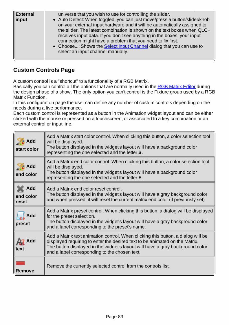
Externalinput
Input channel: The individual input channel within the selected inputuniverse that you wish to use for controlling the slider.Auto Detect: When toggled, you can just move/press a button/slider/knobon your external input hardware and it will be automatically assigned tothe slider. The latest combination is shown on the text boxes when QLC+receives input data. If you don't see anything in the boxes, your inputconnection might have a problem that you need to fix first.Choose...: Shows the Select Input Channel dialog that you can use toselect an input channel manually.
Custom Controls Page
A custom control is a "shortcut" to a functionality of a RGB Matrix.Basically you can control all the options that are normally used in the RGB Matrix Editor duringthe design phase of a show. The only option you can't control is the Fixture group used by a RGBMatrix Function.In this configuration page the user can define any number of custom controls depending on theneeds during a live performance.Each custom control is represented as a button in the Animation widget layout and can be eitherclicked with the mouse or pressed on a touchscreen, or associated to a key combination or anexternal controller input line.
Add
start color
Add a Matrix start color control. When clicking this button, a color selection toolwill be displayed.The button displayed in the widget's layout will have a background colorrepresenting the one selected and the letter S.
Add
end color
Add a Matrix end color control. When clicking this button, a color selection toolwill be displayed.The button displayed in the widget's layout will have a background colorrepresenting the one selected and the letter E.
Add
end colorreset
Add a Matrix end color reset control.The button displayed in the widget's layout will have a gray background colorand when pressed, it will reset the current matrix end color (if previously set)
Add
preset
Add a Matrix preset control. When clicking this button, a dialog will be displayedfor the preset selection.The button displayed in the widget's layout will have a gray background colorand a label corresponding to the preset's name.
Add
text
Add a Matrix text animation control. When clicking this button, a dialog will bedisplayed requiring to enter the desired text to be animated on the Matrix.The button displayed in the widget's layout will have a gray background colorand a label corresponding to the chosen text.
RemoveRemove the currently selected control from the controls list.
Page 83
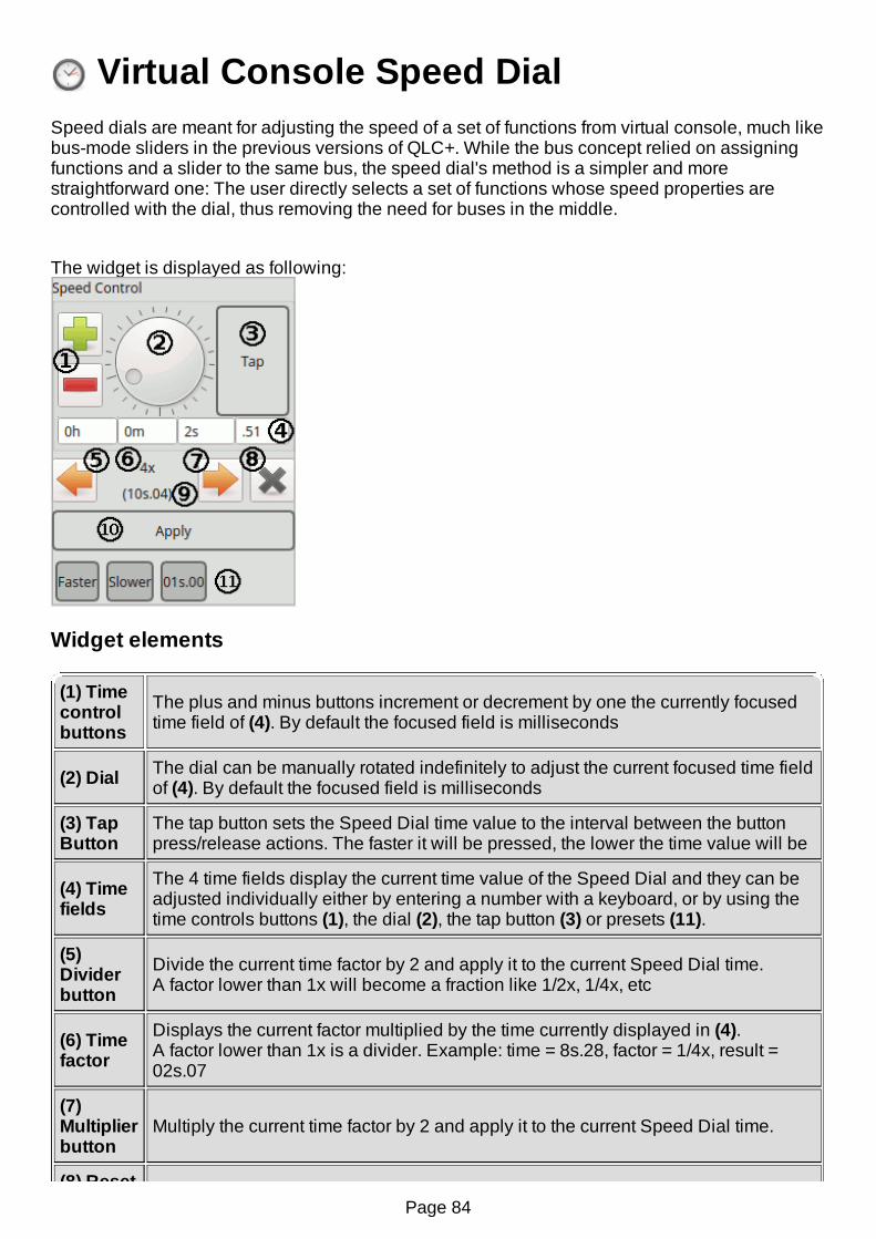
Virtual Console Speed DialSpeed dials are meant for adjusting the speed of a set of functions from virtual console, much likebus-mode sliders in the previous versions of QLC+. While the bus concept relied on assigningfunctions and a slider to the same bus, the speed dial's method is a simpler and morestraightforward one: The user directly selects a set of functions whose speed properties arecontrolled with the dial, thus removing the need for buses in the middle.
The widget is displayed as following:
Widget elements
(1) Timecontrolbuttons
The plus and minus buttons increment or decrement by one the currently focusedtime field of (4). By default the focused field is milliseconds
(2) Dial The dial can be manually rotated indefinitely to adjust the current focused time fieldof (4). By default the focused field is milliseconds
(3) TapButton
The tap button sets the Speed Dial time value to the interval between the buttonpress/release actions. The faster it will be pressed, the lower the time value will be
(4) Timefields
The 4 time fields display the current time value of the Speed Dial and they can beadjusted individually either by entering a number with a keyboard, or by using thetime controls buttons (1), the dial (2), the tap button (3) or presets (11).
(5)Dividerbutton
Divide the current time factor by 2 and apply it to the current Speed Dial time.A factor lower than 1x will become a fraction like 1/2x, 1/4x, etc
(6) Timefactor
Displays the current factor multiplied by the time currently displayed in (4).A factor lower than 1x is a divider. Example: time = 8s.28, factor = 1/4x, result =02s.07
(7)Multiplierbutton
Multiply the current time factor by 2 and apply it to the current Speed Dial time.
(8) ResetPage 84

(8) Resetbutton Reset the current time factor to 1x and apply it to the current Speed Dial time.
(9)Factoredtime
Displays the result of the Speed Dial time multiplied by the current time factor (6)
(10)Applybutton
Applies the current Speed Dial time to the Functions associated. This is usefulwhen multiple Speed Dials are present in a Virtual Console
(11)Presetbuttons
This area displays the time presets, if present, added by the user
Operation
The speed dial itself looks and works just as the same as the speed dials in various functioneditors: There is a big dial (2) in the middle that increases the time when rotated clockwise anddecreases it when rotated counter-clockwise. The plus and minus buttons (1) are analternative way of adjusting the speed.
The current time value (4) is displayed in four parts. When any of these fields is clicked, the dialand the plus/minus buttons will increase/decrease that unit of time. The mouse wheel can alsobe used instead of the dial/buttons and the fields also accept values entered on the numerickeypad.
h: Hoursm: Minutess: Seconds.xx: Centiseconds (100ths of a second)
The tap button (3) can be used to match the time to a beat. The elapsed time between clicks ismeasured and this time is set for the controlled functions, just as if the dial had been adjusted tothat particular time.
For cuelists/chasers and RGB Matrices, the tap button advances the function to next step/positionwhen speed dial is set to adjust duration. The tapped tempo must be more than 1/4 of the originalduration.
Configuration - Functions tab
Speed dials can be configured with the properties button found in the toolbar or by doubleclicking the speed dial itself.
Speed DialName Change the dial's name.
Displays the list of functions, whose speed value(s) are being controlled bythe dial.
For each speed value (fade in, fade out, duration), it is possible to set amultiplier.
Fade In factor Select a multiplier to adjust the functions' fade inspeed
Page 85
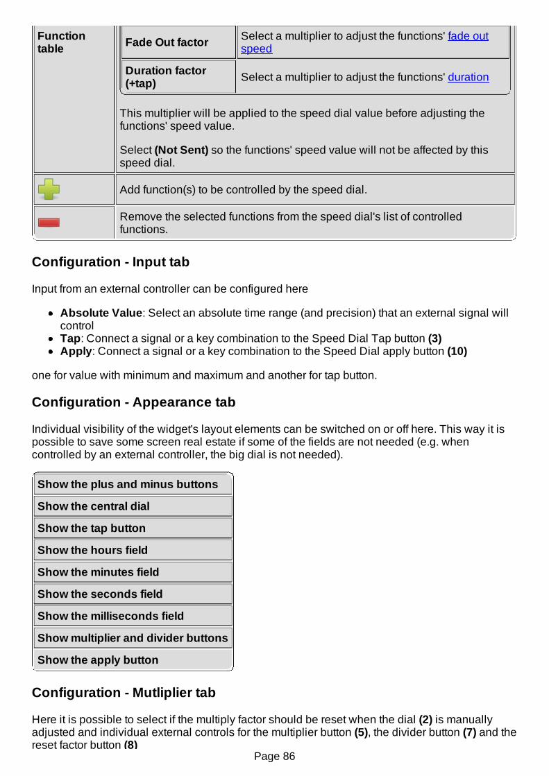
Functiontable Fade Out factor Select a multiplier to adjust the functions' fade out
speed
Duration factor(+tap) Select a multiplier to adjust the functions' duration
This multiplier will be applied to the speed dial value before adjusting thefunctions' speed value.
Select (Not Sent) so the functions' speed value will not be affected by thisspeed dial.
Add function(s) to be controlled by the speed dial.
Remove the selected functions from the speed dial's list of controlledfunctions.
Configuration - Input tab
Input from an external controller can be configured here
Absolute Value: Select an absolute time range (and precision) that an external signal willcontrolTap: Connect a signal or a key combination to the Speed Dial Tap button (3)Apply: Connect a signal or a key combination to the Speed Dial apply button (10)
one for value with minimum and maximum and another for tap button.
Configuration - Appearance tab
Individual visibility of the widget's layout elements can be switched on or off here. This way it ispossible to save some screen real estate if some of the fields are not needed (e.g. whencontrolled by an external controller, the big dial is not needed).
Show the plus and minus buttons
Show the central dial
Show the tap button
Show the hours field
Show the minutes field
Show the seconds field
Show the milliseconds field
Show multiplier and divider buttons
Show the apply button
Configuration - Mutliplier tab
Here it is possible to select if the multiply factor should be reset when the dial (2) is manuallyadjusted and individual external controls for the multiplier button (5), the divider button (7) and thereset factor button (8)
Page 86
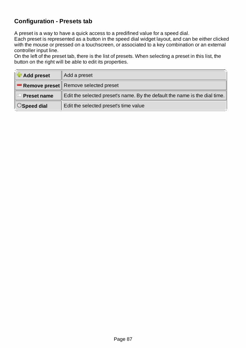
Configuration - Presets tab
A preset is a way to have a quick access to a predifined value for a speed dial.Each preset is represented as a button in the speed dial widget layout, and can be either clickedwith the mouse or pressed on a touchscreen, or associated to a key combination or an externalcontroller input line.On the left of the preset tab, there is the list of presets. When selecting a preset in this list, thebutton on the right will be able to edit its properties.
Add preset Add a preset
Remove preset Remove selected preset
Preset name Edit the selected preset's name. By the default the name is the dial time.
Speed dial Edit the selected preset's time value
Page 87

Virtual Console Cue ListA Cue List provides a list of Functions that you can step through with a single keyboard key. TheCue List is designed for theatrical performances where the lighting operator needs only to followthe script and toggle the next cue as the performance goes on.
The first column on the Cue List displays the cue number that runs from 1 to infinity and beyond .The second column shows the individual Function name that has been assigned to thatparticular cue.
Please note that only Chasers can be assigned to a Cue List, for the simple reason that theChaser is the only function with a duration. Since any other Function can be added as a step to aChaser with the Chaser Editor, it is simple to create the desired Cues by mixing Scenes,Collections, and so on...
Configuration
Cue Lists can be configured with the object properties button found in the toolbar or bydouble clicking on the Cue List widget.
Cue listname
Set the friendly name of the Cue List. The name appears as the Cue List's secondcolumn title.
Cue list
Chaser: Select the Chaser to associate with the Cue List.
Associate a Chaser with the Cue List using the Select Function dialog.
Detach the selected Chaser from the Cue List.
Playback buttons layout: Select how the playback can be controlled with the twoavailable buttons.Behavior of the Next/Previous buttons when the chaser is not active: Selectthe behaviour of the Next and Previous buttons when the Chaser is not running.Basically this option determines the action that should be taken when the Chaseris started for the first time or when the Chaser is stopped at any cue in the list.The possible choices are:
Run chaser from first/last cue (default): This is the default behaviour and itwill run the Chaser with its original running order (Normal or Reverse)Run chaser from next/previous cue: Start the Chaser from the cue where ithas been interruptedSelect next/previous cue: This performs only a selection of a cue, withoutrunning the ChaserDo nothing: No action is taken in this case. This is useful when working onlywith the Play/Stop button
PlaybackYou can select the key that you want to use to start/stop the selected cue in theCue List with this option. The key combination is shown in the text field; if the fieldis empty, there is no key combination currently attached to the Cue List.
Next cueYou can select the key that you want to use to skip to the next cue in the Cue Listwith this option. The key combination is shown on the text field; if the field is empty,there is no key combination currently attached to the Cue List.
Page 88
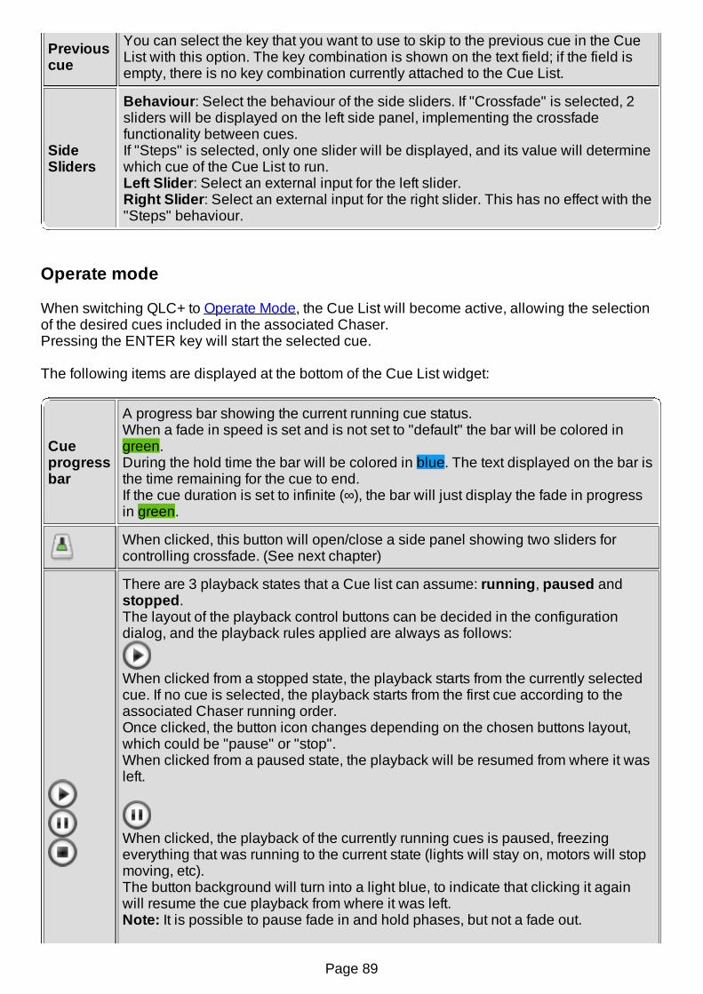
Previouscue
You can select the key that you want to use to skip to the previous cue in the CueList with this option. The key combination is shown on the text field; if the field isempty, there is no key combination currently attached to the Cue List.
SideSliders
Behaviour: Select the behaviour of the side sliders. If "Crossfade" is selected, 2sliders will be displayed on the left side panel, implementing the crossfadefunctionality between cues.If "Steps" is selected, only one slider will be displayed, and its value will determinewhich cue of the Cue List to run.Left Slider: Select an external input for the left slider.Right Slider: Select an external input for the right slider. This has no effect with the"Steps" behaviour.
Operate mode
When switching QLC+ to Operate Mode, the Cue List will become active, allowing the selectionof the desired cues included in the associated Chaser.Pressing the ENTER key will start the selected cue.
The following items are displayed at the bottom of the Cue List widget:
Cueprogressbar
A progress bar showing the current running cue status.When a fade in speed is set and is not set to "default" the bar will be colored ingreen.During the hold time the bar will be colored in blue. The text displayed on the bar isthe time remaining for the cue to end.If the cue duration is set to infinite (∞), the bar will just display the fade in progressin green.
When clicked, this button will open/close a side panel showing two sliders forcontrolling crossfade. (See next chapter)
There are 3 playback states that a Cue list can assume: running, paused andstopped.The layout of the playback control buttons can be decided in the configurationdialog, and the playback rules applied are always as follows:
When clicked from a stopped state, the playback starts from the currently selectedcue. If no cue is selected, the playback starts from the first cue according to theassociated Chaser running order.Once clicked, the button icon changes depending on the chosen buttons layout,which could be "pause" or "stop".When clicked from a paused state, the playback will be resumed from where it wasleft.
When clicked, the playback of the currently running cues is paused, freezingeverything that was running to the current state (lights will stay on, motors will stopmoving, etc).The button background will turn into a light blue, to indicate that clicking it againwill resume the cue playback from where it was left.Note: It is possible to pause fade in and hold phases, but not a fade out.
Page 89

When clicked, the currently running cue will be stopped, and the cue selection willstay on the last played cue. Any paused state will be reset and lights will be shutdown.If the buttons layout is "Play/Pause + Stop", pressing this button for the secondtime, will bring back the selected cue to the first cue of the Chaser (or the last if therunning order is reversed)
Go back to the previous cue in the Cue List, which will then be reproduced. Whenthe top is reached, the previous cue will be the last cue of the Cue List
Go to the next cue in the Cue List, which will then be reproduced. When reachingthe bottom, the next cue will be the first of the Cue List
Crossfade
There are two faders that can be used to manually control crossfade between two consecutivecues.
Each slider is connected to a cue and to help understanding their purpose we'll call them "currentcue" and "next cue" sliders.The label at the bottom of each slider will show the number of the cue that the slider is controllingand a color to show the status of that cue.
There are two check boxes at the top:
Blend: if checked, will activate an additive blend mode between the two cues beingcrossfaded.This means that the DMX channels affected by the faded cues will be subject to a sort of"morphing" between each other.In this way, DMX channels with the same value will not change at all.Link: will link the sliders together to facilitate crossfading between cues, for example byusing a single external fader instead of two.
When the Cue list is running, the crossfade sliders control the intensity of the associated cues,overriding their Fade In and Fade Out speeds and so allowing manual control of the transition.
The slider for the current cue has a blue label. This will be at 100% when the playback of the CueList is started.The slider for the next cue has an orange label and will be at 0% when the playback of the CueList is started.The intensities of both cues can be adjusted by moving the corresponding slider.
However, after both sliders have been moved to the opposite ends of their travel, the followingchanges take place:The orange next cue label changes to blue (slider at 100%). This indicates that the old next cuehas become the new current cue.The blue current cue label changes to orange and the number of the cue is increased by 2 (sliderat 0%). So this slider now controls the cue which comes after the old next cue.
Hint
Page 90

When a cue is added to a Chaser using the Chaser Editor, the default duration is set to 0.To avoid the cues in the Cue List looping frantically without any result, set the duration of your
cues, either by double clicking on the duration field or by using the Speed Dial widgetNote that if you need scenes that you're going to crossfade manually with the Cue List widget,you probably will want to set the duration of the cues to "infinite" (∞) using the Speed Dial widget.
This can be enabled in the Chaser Editor by clicking on the button.
Page 91
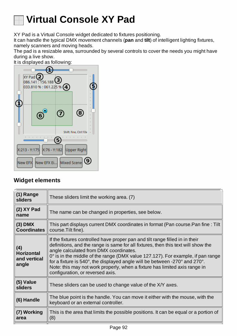
Virtual Console XY PadXY Pad is a Virtual Console widget dedicated to fixtures positioning.It can handle the typical DMX movement channels (pan and tilt) of intelligent lighting fixtures,namely scanners and moving heads.The pad is a resizable area, surrounded by several controls to cover the needs you might haveduring a live show.It is displayed as following:
Widget elements
(1) Rangesliders These sliders limit the working area. (7)
(2) XY Padname The name can be changed in properties, see below.
(3) DMXCoordinates
This part displays current DMX coordinates in format (Pan course.Pan fine : Tiltcourse.Tilt fine).
(4)Horizontaland verticalangle
If the fixtures controlled have proper pan and tilt range filled in in theirdefinitions, and the range is same for all fixtures, then this text will show theangle calculated from DMX coordinates.0° is in the middle of the range (DMX value 127.127). For example, if pan rangefor a fixture is 540°, the displayed angle will be between -270° and 270°.Note: this may not work properly, when a fixture has limited axis range inconfiguration, or reversed axis.
(5) Valuesliders These sliders can be used to change value of the X/Y axes.
(6) Handle The blue point is the handle. You can move it either with the mouse, with thekeyboard or an external controller.
(7) Workingarea
This is the area that limits the possible positions. It can be equal or a portion of(8)
Page 92
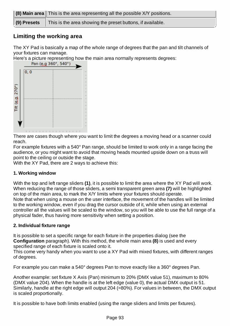
(8) Main area This is the area representing all the possible X/Y positions.
(9) Presets This is the area showing the preset buttons, if available.
Limiting the working area
The XY Pad is basically a map of the whole range of degrees that the pan and tilt channels ofyour fixtures can manage.Here's a picture representing how the main area normally represents degrees:
There are cases though where you want to limit the degrees a moving head or a scanner couldreach.For example fixtures with a 540° Pan range, should be limited to work only in a range facing theaudience, or you might want to avoid that moving heads mounted upside down on a truss willpoint to the ceiling or outside the stage.With the XY Pad, there are 2 ways to achieve this:
1. Working window
With the top and left range sliders (1), it is possible to limit the area where the XY Pad will work.When reducing the range of those sliders, a semi transparent green area (7) will be highlightedon top of the main area, to mark the X/Y limits where your fixtures should operate.Note that when using a mouse on the user interface, the movement of the handles will be limitedto the working window, even if you drag the cursor outside of it, while when using an externalcontroller all the values will be scaled to the window, so you will be able to use the full range of aphysical fader, thus having more sensitivity when setting a position.
2. Individual fixture range
It is possible to set a specific range for each fixture in the properties dialog (see theConfiguration paragraph). With this method, the whole main area (8) is used and everyspecified range of each fixture is scaled onto it.This come very handy when you want to use a XY Pad with mixed fixtures, with different rangesof degrees.
For example you can make a 540° degrees Pan to move exactly like a 360° degrees Pan.
Another example: set fixture X Axis (Pan) minimum to 20% (DMX value 51), maximum to 80%(DMX value 204). When the handle is at the left edge (value 0), the actual DMX output is 51.Similarly, handle at the right edge will output 204 (=80%). For values in between, the DMX outputis scaled proportionally.
It is possible to have both limits enabled (using the range sliders and limits per fixtures).
Page 93

XY Pad usages
The XY Pad allows 3 completely different usages, but all targeted to positioning. It's up to you todecide the best use of them depending on your needs. You also might want to consider theusage of multiple XY Pads with different purposes.
1- Absolute positioning: this is the basic usage and it requires only to specify whichfixtures you intend to control (added via Configuration window) and eventually their specificrange of operation.As previosuly described all you need to do is to setup your fixtures once and start movingthem with your favourite controller.It is also possible to define some position presets, so a number of buttons will be displayedin (9) to quickly recall an absolute position.If a Fixture Group preset is activated, the XY Pad will control the absolute positions only ofthe Fixtures defined in the preset. (see Presets tab for more info)
2- EFX: In the Configuration window (Presets tab), it is possible to add some presets torecall existing EFX functions. When activating a EFX preset, the animated preview of
the fixtures movements will be displayed like this:
If no working window is set, the EFX will be be displayed exactly like it is previewed in theEFX Editor. Otherwise, the EFX will be scaled to fit the defined working window.If a working window is active, it will be shared between usage #1 and usage #2.
3- Relative to a Scene: In the Configuration window (Presets tab), it is also possible to addsome presets to recall existing Scene functions
XY Pad will detect which Pan/Tilt channels are present in the Scene and set them.The Pad handle (6) will automatically position itself to the center of the main area (8).Moving the handle, will produce relative values from the center of the Pad, that will beadded/subtracted to the DMX values of the running Scene.Moving up will add a negative offset to Tilt channels and moving down will add a positiveoffset.Moving left will add a negative offset to Pan channels and moving right will add a positiveoffset.When activating a Scene preset, is a working window is active, it will be hidden, as there'sno absolute values involved in this usage. When switching back to usage #1 or #2, theworking window will be restored.
Page 94
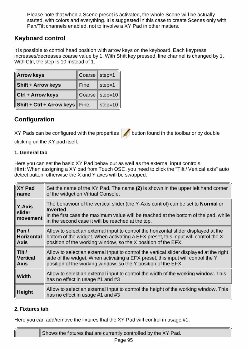
Please note that when a Scene preset is activated, the whole Scene will be actuallystarted, with colors and everything. It is suggested in this case to create Scenes only withPan/Tilt channels enabled, not to involve a XY Pad in other matters.
Keyboard control
It is possible to control head position with arrow keys on the keyboard. Each keypressincreases/decreases coarse value by 1. With Shift key pressed, fine channel is changed by 1.With Ctrl, the step is 10 instead of 1.
Arrow keys Coarse step=1
Shift + Arrow keys Fine step=1
Ctrl + Arrow keys Coarse step=10
Shift + Ctrl + Arrow keys Fine step=10
Configuration
XY Pads can be configured with the properties button found in the toolbar or by double
clicking on the XY pad itself.
1. General tab
Here you can set the basic XY Pad behaviour as well as the external input controls.Hint: When assigning a XY pad from Touch OSC, you need to click the "Tilt / Vertical axis" autodetect button, otherwise the X and Y axes will be swapped.
XY Padname
Set the name of the XY Pad. The name (2) is shown in the upper left hand cornerof the widget on Virtual Console.
Y-Axisslidermovement
The behaviour of the vertical slider (the Y-Axis control) can be set to Normal orInverted.In the first case the maximum value will be reached at the bottom of the pad, whilein the second case it will be reached at the top.
Pan /HorizontalAxis
Allow to select an external input to control the horizontal slider displayed at thebottom of the widget. When activating a EFX preset, this input will control the Xposition of the working window, so the X position of the EFX.
Tilt /VerticalAxis
Allow to select an external input to control the vertical slider displayed at the rightside of the widget. When activating a EFX preset, this input will control the Yposition of the working window, so the Y position of the EFX.
Width Allow to select an external input to control the width of the working window. Thishas no effect in usage #1 and #3
Height Allow to select an external input to control the height of the working window. Thishas no effect in usage #1 and #3
2. Fixtures tab
Here you can add/remove the fixtures that the XY Pad will control in usage #1.
Shows the fixtures that are currently controlled by the XY Pad.Page 95

Fixtureslist
Fixture: The names of each fixtureX-Axis: Shows the value range (and reversal if applicable) of the horizontal(Pan) axis for each fixtureY-Axis: Shows the value range (and reversal if applicable) of the vertical (Tilt)axis for each fixture
Add Fixtures to be controlled by the XY Pad, using the Select Fixture dialog.NOTE: Only those fixtures that have Pan and Tilt channels are shown in the dialog.
Remove the selected fixtures from the XY Pad's control list.
Edit the selected fixture's behaviour as controlled by the XY Pad.
2.1 Fixture movement configuration
You can change the extent of movement and reverse fixtures' movement with the XY Pad FixtureConfiguration dialog.
Horizontal X-AxisMinimum: Set the minimum pan limit for the fixtureMaximum: Set the maximum pan limit for the fixtureReverse: Reverse fixture's movement on the horizontal (pan) axis
Vertical Y-AxisMinimum: Set the minimum tilt limit for the fixtureMaximum: Set the maximum tilt limit for the fixtureReverse: Reverse fixture's movement on the vertical (tilt) axis
3. Presets tab
Here you can add/remove presets to the XY Pad. Each preset is displayed as a button in thelower part of the XY Pad widget. EFX nad Scenes presets can be toggled, to start/stop a function,Fixture Groups presets can be toggled to activate/deactivate a Fxiture group, while Positionpresets can be clicked just once
Presets list Show the list of the presets currently added to the XY Pad
Add
position
When clicking on this button, a new position preset is created and added to theXY Pad. By default the preset name are the X/Y coordinates at the moment ofthe creation
Add
EFX
When clicking on this button, the Select Function dialog is displayed, allowingyou to choose an existing EFX from your workspace.When done, a new EFX preset is created and added to the XY Pad. By defaultthe preset name is the EFX name
Add
Scene
When clicking on this button, the Select Function dialog is displayed, allowingyou to choose an existing Scene from your workspace.When done, a new Scene preset is created and added to the XY Pad. By defaultthe preset name is the Scene name.Note that if the selected Scene doesn't have any Pan or Tilt channels, an error isdisplayed and no preset is created.
When clicking on this button, the Select Fixture dialog is displayed, allowing youPage 96

Add
FixtureGroup
to create a group of Fixtures as a subgroup of the Fixtures the XY Pad iscontrolling (defined in the Fixtures tab)When clicking on a Fixture Group preset in Operate mode, the XY Pad willcontrol only the Fixture positions of the activated Fixture Group.Note: A Fixture Group preset has no effect on EFX and Scene presets.
RemoveRemoves the currently selected preset
Presetname Allows to enter an arbitrary name for the currently selected preset
Externalinput Allows to select an external input control for the currently selected preset
Keycombination Allows to select a keyboard combination for the currently selected preset
Page 97
Virtual Console LabelA Label is simply text field that can be placed on the Virtual Console to give additionalinformation, for example, as a heading for a group of buttons or the title of a frame.
Configuration
You can only set up the text to be displayed in a Label with the Rename button. It does nothave any other purpose nor configurable options, other than the standard styling & placementoptions that all Virtual Console widgets have.
Page 98

Virtual Console Audio TriggersStarting from QLC+ version 4.4.0, this functionality allows you to use an audio input source suchas a microphone, to add more life to your light shows.
Introduction
When clicking on the icon, an audio trigger widget will be added to your Virtual Console.The widget's graphics area shows live monitoring of the captured audio, displaying a number ofspectrum bars and a volume bar.On the bottom you can see the range of frequencies analyzed by QLC+
ConfigurationWhen double clicking on the widget in design mode, a panel is displayed showing a completeset of options to tune the audio trigger's functionality.The first thing you can configure is the number of spectrum bars that you want to display and thatyou will need during your live show. The number accepted is between 5 and 32.Once the number of bars has been decided, you can proceed to assign a functionality to eachbar. There is a list showing the following options for the volume and spectrum bars:
Name Can be "Volume Bar" or a spectrum bar shown as #number (start frequency - endfrequency). Example: #5 (1250Hz - 1562Hz)>
Type
Indicates the type of functionality the bar will control. It can be:
None - No functionality assigned
DMX - Controls single DMX channels
Function - Controls a QLC+ function
VC Widget - Controls a Virtual Console widget (at the moment onlybuttons, sliders, tapping of speed dials and next cue of cue lists)
AssignWhen a type is selected, a button with a icon is displayed to allow you toconnect the bar to the desired functionality. Depending on which type you chose,clicking on this button will display the DMX channels, Functions or Virtual Consolewidgets selection dialogs.
Info
This column displays some additional information about the bar--functionalityassociation.Depending on the type you chose, you will find the number of DMX channels, thefunction name or the VC Widget name selected displayed here
Disablethreshold
When selecting a Function or a VC Widget button, this column allows you to set adeactivation threshold percentage. When the spectrum or volume bar goes belowthis value, the associated function/VC button will be stopped/deactivated.
Enablethreshold
When selecting a Function or a VC Widget button, this column allows you to set anactivation threshold percentage. When the spectrum or volume bar goes above
Page 99

threshold this value, the associated function/VC button will be started/activated.
Divisor
For speed dials and cue lists, this will divide the taps by the selected number -only every n-th tap will be actually sent to the speed dial. In other words, the taphappens only on every n-th beat. If you want the tap on every beat, enter 1, forevery other beat enter 2. For once in a 4/4 measure, enter 4. For once in 3 4/4measures, enter 12. Maximum is 64.
DMX channels
You can choose one or more channels of the currently patched fixtures. Those channels will beset proportionally to total volume, or volume in a particular frequency band.
Functions
You can select one or more functions. Those functions are started when volume goes above theEnable threshold in respective band, and stopped when it goes below the Disable threshold.
VC Widgets
You can select only ONE widget here, either a button, a slider or a speed dial. Depending on thetype:
Button is pressed when volume goes above Enable threshold, and released when thevolume is below Disable threshold (similar to functions).Slider is moved in proportion to the volume (similar to DMX channels). For a slider thethresholds do not apply.Speed dial is tapped.Cue List "Next Cue" is pressed.
For Speed dials and Cue Lists, the tap/button press happens when the volume goes above theEnable threshold, and won't happen again until the volume falls below the Disable threshold.This probably means you will have to set the thresholds a little closer to each other than forbuttons.
Page 100
Select Input ChannelWhenever an Input Channel needs to be selected, for example when manually attaching achannel from an Input Plugin to a Virtual Console widget, the Select Input Channel dialog isused.
The dialog is very straightforward; there is a list of input universes and each universe that has anInput Line attached to it, displays the line's (or the attached device's) name after the universenumber. Under each operational universe, there is a list of channels provided by that universe.You can choose from these channels or select one manually.
If you have an Input Profile attached to the universe, you see the individual channel names andnumbers for the device. If there isn't a Profile attached to an input universe, you will need to typethe channel number manually, by double-clicking the item that tells you to do that and then typein the channel number manually. See also the tutorial on input profiles
NOTE: All Virtual Console widgets that have been made external-input-aware, provide an optionfor automatically detecting the input channel as well, so that you don't need do this selectionmanually.
Page 101

Virtual Console Widget Styling & PlacementThe colors, font, frame style, stacking order, size and placement of widgets can be changed tobetter suit your vision of the perfect lighting console. Most of these options, except for moving andresizing, are available in the Virtual Console Edit menu, that is, they can be accessed from themenu bar as well as from a popup menu by right clicking a widget you wish to adjust.
NOTE: The Virtual Console widgets' styling and placement options are available only when theapplication is in Design Mode.
Moving Widgets
Widgets can be moved simply by dragging them as if you were dragging any icon on yourdesktop. Refer to your operating system manual on how to drag items.
To move a widget from one frame to another frame, you need to move the widget through theVirtual Console clipboard. Cut the widgets from the first frame, then select another frame andpaste the widgets into that frame.
Resizing Widgets
Each widget has a special resize handle on their lower right hand corner that you can graband then resize the widget as appropriate simply by dragging the handle.
Widget Background
To change a widget's background color, choose Color from the Background menu and select acolor from the popup dialog. To set an image as the widget's background, choose Image from theBackground menu and select an image file from the popup dialog.
To restore the default background color (and to clear an image), choose Default from theBackground menu.
NOTE: Some operating systems and/or visual themes do not allow manual setting of backgroundcolors or images. Try changing the desktop theme if you encounter this problem.
Widget Foreground
To change a widget's foreground color, choose Color from the Foreground menu and select acolor from the popup dialog.
Buttons can have an icon in the foreground, which will override any text set as their name. Tochange a button's icon, select Choose... from the Icon menu and select an image file from thepopup dialog.
To restore the default background color (and to clear an icon if applicable), choose Default fromthe Background menu.
NOTE: Some operating systems and/or visual themes do not allow manual setting of foregroundcolors or images. Try changing the desktop theme if you encounter this problem.
Widget Borders
To change the border style for a widget, you can choose either Raised or Sunken from the
Page 102

Border menu. To completely remove the borders of a widget, choose None from the Bordermenu.
NOTE: Some operating systems and/or visual themes do not allow manual setting of borders. Trychanging the desktop theme if you encounter this problem.
Fonts
You can change the font for all child widgets of a frame at the same time by changing the font ofthe frame itself. Alternatively, you can change the font for each widget separately. Fonts can bechanged by selecting Font... from the Font menu. To restore the font back to the widget's parentframe's font, select Default from the Font menu.
Widget Stacking Order
In addition to the normal 2-dimensions, vertical and horizontal, you can also adjust widgets'placement in the 3rd dimension: depth. If you see a widget going behind another control, you canraise the widget on top of all other widgets by selecting Raise from the Stacking Order menu.Likewise, if you wish to put a widget behind all other widgets, you can select Lower from theStacking Order menu.
Page 103
Simple DeskThe simple desk emulates a typical lighting console that is able to control a full 512-channelDMX universe with a multiple cue stacks operated with playback sliders.Simple desk is divided into two main areas: channels (top area) and cues (bottom area).The channels area reflects exactly the current status of each DMX channel of each universe. Ifchannels are controlled with no project loaded, users have a completely manual control of them.When a project is loaded, instead, moving a Simple desk channel will override any other QLC+function trying to control that channel. A visual indication will turn the channel background to red,informing the user that Simple desk now has the total control of it.This is very useful in some live circumstances where a running function needs some manualadjustment.To "disengage" Simple desk from overriding channels, just click on the reset button. Resettingchannels will either bring them back to zero or to the value previously set by a function.
Cues operates separately from other QLC+ components. For example, cues within the cue stackare not visible in the Function Manager and Scenes are not visible in the cue stack.
Controls - UniverseThe universe box contains the sliders that are used to control individual DMX channels in the firstDMX universe. Since 512 sliders cannot fit nicely on the screen at the same time, they have beendivided into pages. By default, each page contains 32 sliders but that can be tuned.
Switch the view mode from all channels to fixture channels. Please note that if nofixtures has been defined, the second mode will produce an empty result
Skip to the previous DMX page.
Universepagebox
Displays the current DMX page. You can skip to a page by writing the pagenumber directly into this box or use the mouse wheel to skip between pagesquickly.
Skip to the next DMX page.
Reset all DMX sliders back to zero or to the value previously set by a function.
GM The Grand Master
Controls - PlaybackThe playback box contains a bunch of playback sliders each of which may contain a cue stack.The playbacks can be used to "play back" the contents of their cue stacks and they can also beused to adjust their overall intensity of the cue.
Select the currently-active playback, whose cue stack is shown on the right side ofthe screen.
Playbackslider
Adjust the intensity of playback's cue stack. When the slider is drawn all the way tozero, the cue stack is stopped. Any value above zero will start replaying the
Page 104
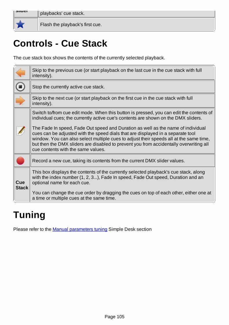
slider playbacks' cue stack.
Flash the playback's first cue.
Controls - Cue StackThe cue stack box shows the contents of the currently selected playback.
Skip to the previous cue (or start playback on the last cue in the cue stack with fullintensity).
Stop the currently active cue stack.
Skip to the next cue (or start playback on the first cue in the cue stack with fullintensity).
Switch to/from cue edit mode. When this button is pressed, you can edit the contents ofindividual cues; the currently active cue's contents are shown on the DMX sliders.
The Fade In speed, Fade Out speed and Duration as well as the name of individualcues can be adjusted with the speed dials that are displayed in a separate toolwindow. You can also select multiple cues to adjust their speeds all at the same time,but then the DMX sliders are disabled to prevent you from accidentally overwriting allcue contents with the same values.
Record a new cue, taking its contents from the current DMX slider values.
CueStack
This box displays the contents of the currently selected playback's cue stack, alongwith the index number (1, 2, 3...), Fade In speed, Fade Out speed, Duration and anoptional name for each cue.
You can change the cue order by dragging the cues on top of each other, either one ata time or multiple cues at the same time.
TuningPlease refer to the Manual parameters tuning Simple Desk section
Page 105

Input/Output Mapping HowtoThis howto document tells you how to patch plugins and their input/output lines (physicalinput/output devices) to QLC+'s universes.
By default QLC+ provides 4 universes but you can add/remove them as needed.The input/output mapping is saved in the currently loaded project. This allows you to port yourproject on another computer/OS without the need to reconfigure it every time.If no project is loaded, QLC+ will keep the I/O mapping as a "fallback" configuration.
Input/Output Manager
To access the Input/Output Manager, just click on the tab with the icon placed on the bottomof the QLC+ main screen.The screen is composed in this way:
On the left hand side there is the list of internal universes that QLC+ can manageOn the right hand side there is the list of devices and their mapped inputs, outputs andfeedback lines that QLC+ has detectedOn the bottom right hand side there is a panel displaying brief information on the currentlyselected device
Every device has a checkbox whenever an input, output or feedback line is available.Each QLC+ universe can map a single input, a single output and a single feedback line
Some plugins might require configuration before they can be used' so you might not be able tosee all inputs/outputs at first. The configuration button is place next to the information panel and itis enabled if the plugin allows any manual setting.
The button icon is:
Adding/Removing universesQLC+ supports any number of universes, depending on the CPU limit of the device controllingthem.On the left hand side of the Input/Output Manager there is a toolbar where you can add/remove,name and configure universes.
Add a new universe. The universe will have a name like "Universe X", whereX is a progressive number assigned by QLC+ (and also the Universe ID).
Remove the currently selected universe.Please be careful with this operation as it can compromise your projectand cannot be reverted.When deleting a universe, if it is currently patched or some fixtures are mappedon it, a popup message will appear asking for confirmation if the operationshould be completed or abandoned.
Universename An arbitrary string that you can set to quickly identify the meaning of a Universe
Passthrough See below
Page 106

PatchingTo patch a plugin's input/output line to the selected universe, you need to place a checkmark onthat particular plugin's input/output line. You can have only one line assigned to a universe at atime, so when you check another line, the checkmark will move from its previous position to theone you just checked.If you don't see any line on a plugin, it means you don't have any device that QLC+ understandsand you're left with the one and only (non-selectable) choice: None.
When an input/output line is checked, the corresponding universe information on the left handside of the screen will change and will display the new configuration set.The plugin information on the bottom right hand side of the screen will change as well and willgive you the new status of the plugin line.
Universe PassthroughWhen passthrough is enabled, universe just forwards what it receives in its input line to its outputline. This is useful for several things:
Protocol converter: when you want to use QLC+ to act as a "protocol" converter. Forexample you can use this feature to transparently map an ArtNet network to a DMX USBadapter or even MIDI.Monitor external data: patch fixtures and watch the data in DMX monitorMerge data from external controller: Have external lighting desk control some of thechannels independently (for example conventionals) and QLC+ control intelligent lights onthe same universe.Raspberry Pi: forward data from QLC+ on PC while programming scenes; when theworkspace is transferred, Raspberry becomes main controller; the devices are alwaysconnected to RPi
Passthrough data is not affected by QLC+ grandmaster or channel modifiers. It is merged in HTPfashion with QLC+ output if there are any fixtures patched at that channel (Note: it does not useLTP/HTP channel settings). Blackout affects passthrough data.
Input and FeedbacksWhen a plugin input line is checked, it gets enabled right away, so you can perform a basic testto double check if your hardware is working properly with QLC+.
Just move a fader/knob on your external device, and if everything works fine, you will see a icon appearing beside the corresponding universe on the left side of the screen.
If your input device supports a return channel, QLC+ can send a visual/mechanical feedback to it.Devices such as Behringer BCF2000 support this feature.At the moment feedbacks are supported only through MIDI, OSC and loopback.
To learn how to setup your external input device for the best use with QLC+, please continueyour reading with the howto for input profiles.
Page 107

Input Profiles HowtoThis howto document tells you how to associate input profiles to input universes and how to editthese profiles. You should first read the howto on input/output mapping so that you can accessthe input/output manager and know how to edit input universes.
Input Profile Manager
To access the Input/Output Manager, just click on the tab with the icon placed on the bottomof the QLC+ main screen.Select the desired universe on the left part of the screen and then click the Profile tab placedbeside the Mapping tab on the top right part of the screen.
Profile assignmentYou will see a list of available input profile definitions, with a check mark on None. This meansthat the current universe doesn't have a profile assigned yet. To assign a profile to the universe,simply place a check mark on one of the available profiles by clicking on the empty check box.Only one profile can be assigned to one universe at a time, so the check mark will actually movefrom its previous position to the item that you have just selected.
Add/Edit a ProfileIt is probable that your input profile is not on the list and you need to create one on your own.
Click the create new input profile button to start making a profile definition for yourinput profile. Alternatively, you can edit any existing profile by selecting the appropriate
item and clicking the edit button. The procedure is exactly the same in both casesfrom now on.
Input Profile EditorA dialog is opened with entry fields for Manufacturer, Model and Type.
First enter the profile's manufacturer and the model to these fields and select profile type.
Type is one of:
MIDI - for MIDI profiles, usually used with MIDI pluginOSC - for OSC profiles, used with OSC pluginHID - for HID profiles, used with HID pluginDMX - generic DMX profilesENTTEC - ENTTEC Wing profiles, used with Enttec Wing plugin
So far, the only difference is that MIDI profiles show MIDI message parameters in the channeleditor.
Now click the Channels tab to edit the profile's channels. You have two choices for addingchannel definitions: Manual and Automatic:
Page 108
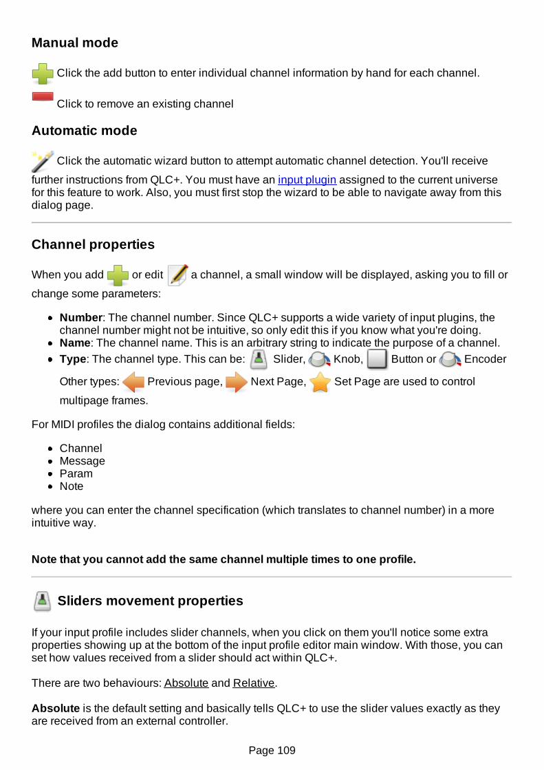
Manual mode
Click the add button to enter individual channel information by hand for each channel.
Click to remove an existing channel
Automatic mode
Click the automatic wizard button to attempt automatic channel detection. You'll receive
further instructions from QLC+. You must have an input plugin assigned to the current universefor this feature to work. Also, you must first stop the wizard to be able to navigate away from thisdialog page.
Channel properties
When you add or edit a channel, a small window will be displayed, asking you to fill or
change some parameters:
Number: The channel number. Since QLC+ supports a wide variety of input plugins, thechannel number might not be intuitive, so only edit this if you know what you're doing.Name: The channel name. This is an arbitrary string to indicate the purpose of a channel.Type: The channel type. This can be: Slider, Knob, Button or Encoder
Other types: Previous page, Next Page, Set Page are used to control
multipage frames.
For MIDI profiles the dialog contains additional fields:
ChannelMessageParamNote
where you can enter the channel specification (which translates to channel number) in a moreintuitive way.
Note that you cannot add the same channel multiple times to one profile.
Sliders movement properties
If your input profile includes slider channels, when you click on them you'll notice some extraproperties showing up at the bottom of the input profile editor main window. With those, you canset how values received from a slider should act within QLC+.
There are two behaviours: Absolute and Relative.
Absolute is the default setting and basically tells QLC+ to use the slider values exactly as theyare received from an external controller.
Page 109

Relative is a more advanced behaviour that comes handy when using a HID Joystick with aQLC+ XY Pad widget or a Slider widget. Values received from an external controller are treatedas relative movement starting from the current position of a Virtual Console widget.Let's make an example. Suppose you have a XY Pad in your Virtual Console, controlling andmonitoring a group of moving heads. During your show you will have a number of scenes movingthe heads pan and tilt. At some point you want to slightly adjust the position of the heads of just afew degrees. Here is when the relative movement kicks in. When you move your joystick (orexternal slider) QLC+ will adjust the heads from their current positions. The direction will dependdirectly from your external controller. The relative movement will stop when the external controllerwill return to its origin. Joysticks have a spring for that.In addition to this, the Input Profile Editor Relative setting allows you to set a Sensitivityparameter that will instruct QLC+ about the strenght of your external controller movements. Thehigher this value is, the slower the movements will occur. The lower, the faster.
Encoder properties
An encoder is an endless rotary control and can be treated only as a relative control. Basicallythe encoder can start at any position and when turned clockwise or counter-clockwise it willgenerate positive or negative offsets inside QLC+. When an Input Profile channel is set to theEncoder type, it is possible to specify a sensitivity value, which is nothing but the relative offsetthat will be added to or subtracted from the current QLC+ channel value.
Button properties
It is possible to change the behaviour of individual buttons from an input profile, and the followingproperties will be used globally in QLC+.
Generate an extra Press/Release when toggled: this is a quite specific option used forexample when dealing with TouchOSC or the Behringer BCF2000.QLC+ toggle events are triggered when a high+low sequence is received. This means that QLC+expects a non zero value (typically 255) followed by a zero value to toggle, for example, a button.Devices like BCF2000 or softwares like TouchOSC, instead, send just a non zero value whenactivating a button, and a zero value when deactivating it.When checking this option, QLC+ will generate the "missing" events to standardize the waysome controller work. So, for example, the BCF2000 will look like sending 255+0 when pressinga button, and another 255+0 when pressing it again.
Custom feedback: with the "Lower value" and "Upper value" boxes, it is possible to forcecustom values to be sent when the selected button sends a non-zero and a zero value.For example, with this option it is possible to set globally how Akai APC devices LEDs should becolored when activated/deactivated.Note that this option is global in QLC+, but it can be overridden if needed by a specific VirtualConsole widget, through its configuration page.
Back to the input profile definitions panelWhen you're done with channels mapping, click the OK button to accept changes and save theinput profile. If you didn't enter a manufacturer/model for the profile, you'll be prompted to enterthem before you can continue.Now you should see the profile you just defined in the list of available input profiles. Rememberhow to assign it to the current universe? Scroll up to Profile assignment if you don't.
Page 110

To remove any existing input profiles, click the remove button. Note that some profiles areso-called system profiles and cannot be removed unless you're the administrator.
That's all !Now you can start using your preferred profile. When assigining an input channel to a QLC+element (like Virtual Console sliders, channel groups, etc..) you will see that your Input profilemapping will be used.
Page 111

Audio Input/Output device selectionThis page describes how to select an input or output audio device to be used inside QLC+.
To access the Input/Output Manager, just click on the tab with the icon placed on the bottomof the QLC+ main screen.Select the desired universe on the left hand side of the screen and then click the Audio tabplaced beside the Profile tab on the top right hand side of the screen.
The list of audio devices detected by QLC+ is displayed. Each device has a checkbox dependingon if it supports input capture or audio output capabilities.The first entry of the list is always "Default device", and it is selected as input and output bydefault. In this way QLC+ will work in most of the cases out of the box.The default device is the one that you currently use to listen to music or to record audio with amicrophone.
If in your system there are additional audio cards (PCI or USB), it is possible to select them in thispanel as the preferred QLC+ input or output device.Basically an input device is used by Virtual Console Audio Triggers while an output device isused by audio functions.
The selection of an audio input/output line should take immediate effect in QLC+. If not you areinvited to restart QLC+ to allow a complete initialization of the internal audio engine.
Page 112

Supported Input DevicesThis table summarizes input devices (controllers) that are known to work with QLC+ and theirsettings. In addition to this list, most MIDI and OSC devices should work with QLC+. Pleaseshare your experiences in QLC+ forum.
Device Type MidiChannel Input Profile MIDI
TemplateSupportsfeedback Comment
Akai APC20 MIDI 1-16 Akai APC20APC20Abletonmode 2
yes
Akai APC40 MIDI 1-16 Akai APC40APC40Abletonmode 2
yes
Akai APC40 Mk2 MIDI 1-16 Akai APC40 Mk2
APC40Mk2Abletonmode
yes
Akai APC Mini MIDI 1 Akai APC MiniAPCminiAbletonmode 2
yes
BehringerBCF2000 indefault mode
MIDI 1 BehringerBCF2000 none yes
BehringerBCF2000 inMackie Controlmode
MIDI 1-16
BehringerBCF2000 inMackie Controlmode
none yes
has morecontrols thanthe defaultmode
BehringerBCR2000 indefault mode
MIDI 1 BehringerBCR2000 none yes
Behringer LC2412 MIDI 1 BehringerLC2412 none no
GLP LightOperator 24 MIDI 1 Showtec
Showmaster 24 none no
should workalso with the48 channelvariant
Elation MIDIcon MIDI 1-16 Elation MIDIcon none yes not tested
Elation StageSetter-24 MIDI 1 Showtec
Showmaster 24 none no
should workalso with the48 channelvariant
Enttec PlaybackWing Enttec - Enttec Playback
Wing - yes
Enttec Shortcut Enttec - Enttec Shortcut - yesPage 113

Wing Enttec - Wing - yes
Generic MIDI MIDI 1 Generic MIDI - no
KorgnanoKONTROL MIDI 1 Korg
nanoKONTROL none no
KorgnanoKONTROL 2 MIDI 1 Korg
nanoKONTROL2 none yes
Korg nanoPAD MIDI 1 Korg nanoPAD none no
Korg nanoPAD 2 MIDI 1 Korg nanoPAD2 none no
Logitech WingmanAttack 2 HID -
LogitechWingman Attack2
- no
NovationLaunchpad MIDI 1 Novation
Launchpad none yes
Novation LaunchControl MIDI 1-16 Novation Launch
Control none yes
ShowtecShowmaster 24 MIDI 1 Showtec
Showmaster 24 none no
should workalso with the48 channelvariant
Stairville LC24 MIDI 1 ShowtecShowmaster 24 none no
should workalso with the48 channelvariant
TouchOSCAutomat5 OSC - TouchOSC
Automat5 - yes
TouchOSC Mix16 OSC - TouchOSCMix16 - yes
Zoom R16 MIDI 1-16 Zoom R16 none no
Page 114

ArtNet input/output plugin
IntroductionQLC+ supports the ArtNet protocol through an input/output plugin that receives and transmitspackets on the network.No extra requirements are needed, since QLC+ has a native implementation of the ArtNetprotocol that works on Linux, Windows and OSX systems.The ArtNet plugin can send and receive packets from multiple network cards, virtual addresses,the loopback device (127.0.0.1) and multiple universes per network interface.By default, ArtNet packets are transmitted as UDP, using the default port 6454 and the broadcastaddress of the selected inteface (e.g. 192.168.0.255). When using the loopback device packetsare always transmitted using address 127.0.0.1.When transmitting multiple universes on the same interface, the packets will be sent by defaultwith an ArtNet Universe ID equal to the QLC+ universe number minus 1.
For example:QLC+ Universe 1 --> ArtNet Universe 0QLC+ Universe 2 --> ArtNet Universe 1...QLC+ Universe 8 --> ArtNet Universe 7
This choice is due to some facts:1- The first valid ArtNet universe is 0 and not 12- The first universe accepted by commercial ArtNet-DMX devices like eDMX and ODE is 0, so tohave QLC+ to work out of the box, the first ArtNet universe must be 0.
If the above settings don't meet the requirements of your network, please read the followingchapter.
Configuration
When clicking on the configuration button, a small dialog will be displayed, showing 2 tabs:the Universes Configuration and the Nodes Tree.
Universes Configuration: after a QLC+ universe is patched with an ArtNet input or output, anentry will be displayed in this list, allowing to manually configure the desired parameters to beused by the ArtNet plugin.Input lines do not have particular parameters, while an output line can be configured wth thefollowing:
IP Address: This is the destination IP address where the ArtNet plugin will transmitpackets to. By default a broadcast address is used (so ending with .255) and by setting thisin the 1-254 range, ArtNet will transmit a QLC+ universe in unicast mode. If your ArtNetnetwork uses a simple hub, the output IP address is irrelevant, as broadcast or unicastdoesn't make any difference. However, if you use a network switch, unicast is fundamentalto balance the network congestion, as every port of the switch is associated to a network IPand will receive only the packets with its destination IP.Note: Do not set the output IP address with the same IP address of your transmitting node(e.g. the PC where QLC+ is running) as it is just wrong and can cause a network loop. Ifyou need to communicate with an ArtNet node running in the same machine where QLC+
Page 115

is running, use the loopback device instead (127.0.0.1).ArtNet Universe: This is the ArtNet universe that will be actually written in every packettransmitted. By setting this parameter, you can use any QLC+ universe to transmit to thedesired ArtNet universe.Transmission Mode: Here you can select if QLC+ should transmit full or partial universes.'Full' means that all the 512 DMX channels of a universe are transmitted at the speed rateof the QLC+ internal clock (50Hz), producing a fixed bitrate of about 200Kbit/s.'Partial', instead, means that QLC+ will transmit only the DMX channel actually used in auniverse, starting from channel 1. For example if you raise channel 3 of a fixture withaddress 50, the ArtNet plugin will transmit only 53 DMX channels, thus limiting thetrasnmission bitrate. Use this setting only if the receiving ArtNet node supports partialtransmission.
Settings that are different from the plugin defaults, will be stored in your QLC+ workspace, toincrease the portability of a project across different platforms, such as different operating systemsor a PC and a Raspberry Pi.
Nodes Tree: This tab displays the ArtNet nodes discovered on the network, grouped by networkinterface.QLC+ will always appear in this list as a node participating to the network.ArtNet nodes are added to this list if they support the ArtPoll/ArtPollReply message, otherwisethey won't appear. This doesn't mean you will not able to communicate with them.
DMXKing eDMX and ENTTEC ODEIf you own one of these devices, they both have configuration tools that might come handy whenworking with QLC+. With them you can set several parameters to match the best configuration toinput/output data from/to QLC+.For example if you want QLC+ universe 3 to output data on the first port of a eDMX, you need touse the tool below to change the device universe address to 2.
Here the links to download the tools:DMXKing eDMX Configuration toolENTTEC Node Management Utility
CompatibilityQLC+ has been tested with the following ArtNet softwares/devices:
DMXking eDMX1 TX - 1 Output deviceDMXking eDMX2 TX - 2 Outputs deviceEnttec Open DMX Ethernet (ODE) - Input/Output deviceOLA - Open Lighting Architecture - Input/Output software nodeArtNet Controller LITE - Input controller for AndroidControlador ArtNet DMX (Lite) - Input controller for AndroidModul8Jinx! - LED Matrix Control
Page 116
DMX USB input/output plugin
1 IntroductionThe DMX USB plugin supports a variety of FTDI-based USB-to-DMX devices:
DMXKing USB DMX512-ADMXKing ultraDMX microDMXKing ultraDMX ProEnttec DMXUSB OpenEnttec DMXUSB ProEnttec DMX USB PRO Mk2DMX4ALL USB-DMX STAGE-PROFI MK2DMX4ALL NanoDMXGus Electronics USB-VL344Vince DMX512 USBElectroTAS USB-DMXFTDI USBCOM 485+
2 ConfigurationDMX USB devices should be automatically detected from QLC+ and displayed in theinput/output panels list.If for some reason the auto-detection fails, you can "force" the type of your DMX USB adaptermanually.
Click on the name of your device and open the configuration dialog by clicking on the iconon the bottom-right side of the panel.You will see a list of DMX USB devices currently connected to your computer. Each one has adrop down menu where you can force the device type.Here's the meaning of each one:
Open TX: Enttec USB DMX Open (and clones) in output modePro RX/TX: Enttec USB DMX Pro or most of the DMXKing devicesPro Mk2: Enttec USB DMX Pro Mk2 - 2 DMX outputs, 1 DMX input, 1 MIDI IN and 1 MIDIOUT ports are availableUltra Pro: DMXKing ultraDMX Pro with 2 outputs and 1 inputDMX4ALL: DMX4ALL USB-DMX STAGE-PROFI MK2Vince Tx: Vince DMX512 USB in output mode
Note for OSX users: If your adapter is detected but doesn't produce any output, most likely you'llfind the solution in the Questions and Answers page.
3 Requirements3.1 LinuxOn all Linux distributions, you need to install libftdi. If you install QLC+ with the Ubuntu SoftwareCenter or some other automatic installer tool, this library will be installed automatically for you.In some cases, if the device doesn't output anything, it might be useful to add your user to the"dialout" group with the following command:
Page 117
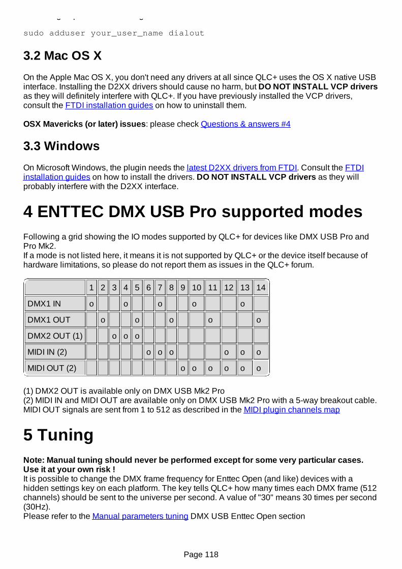
"dialout" group with the following command:
sudo adduser your_user_name dialout
3.2 Mac OS XOn the Apple Mac OS X, you don't need any drivers at all since QLC+ uses the OS X native USBinterface. Installing the D2XX drivers should cause no harm, but DO NOT INSTALL VCP driversas they will definitely interfere with QLC+. If you have previously installed the VCP drivers,consult the FTDI installation guides on how to uninstall them.
OSX Mavericks (or later) issues: please check Questions & answers #4
3.3 WindowsOn Microsoft Windows, the plugin needs the latest D2XX drivers from FTDI. Consult the FTDIinstallation guides on how to install the drivers. DO NOT INSTALL VCP drivers as they willprobably interfere with the D2XX interface.
4 ENTTEC DMX USB Pro supported modesFollowing a grid showing the IO modes supported by QLC+ for devices like DMX USB Pro andPro Mk2.If a mode is not listed here, it means it is not supported by QLC+ or the device itself because ofhardware limitations, so please do not report them as issues in the QLC+ forum.
1 2 3 4 5 6 7 8 9 10 11 12 13 14
DMX1 IN o o o o o
DMX1 OUT o o o o o
DMX2 OUT (1) o o o
MIDI IN (2) o o o o o o
MIDI OUT (2) o o o o o o
(1) DMX2 OUT is available only on DMX USB Mk2 Pro(2) MIDI IN and MIDI OUT are available only on DMX USB Mk2 Pro with a 5-way breakout cable.MIDI OUT signals are sent from 1 to 512 as described in the MIDI plugin channels map
5 TuningNote: Manual tuning should never be performed except for some very particular cases.Use it at your own risk !It is possible to change the DMX frame frequency for Enttec Open (and like) devices with ahidden settings key on each platform. The key tells QLC+ how many times each DMX frame (512channels) should be sent to the universe per second. A value of "30" means 30 times per second(30Hz).Please refer to the Manual parameters tuning DMX USB Enttec Open section
Page 118
E1.31 input/output plugin
IntroductionQLC+ supports the E1.31 protocol (also known as sACN) through an input/output plugin thatreceives and transmits packets on the network.No extra requirements are needed, since QLC+ has a native implementation of the E1.31protocol that works on Linux, Windows and OSX systems.The E1.31 plugin can send and receive packets from multiple network cards, virtual addresses,the loopback device (127.0.0.1) and multiple universes per network interface.By default, E1.31 packets will be sent as UDP on multicast addresses like 239.255.0.x, where 'x'is the universe number selected in QLC+. The port used is 5568.When using the loopback device packets are always transmitted using address 127.0.0.1.When transmitting multiple universes on the same interface, the packets will be sent by defaultwith an E1.31 Universe ID equal to the QLC+ universe.
For example:QLC+ Universe 1 --> E1.31 Universe 1 on 239.255.0.1QLC+ Universe 2 --> E1.31 Universe 2 on 239.255.0.2...QLC+ Universe 8 --> E1.31 Universe 8 on 239.255.0.8
If the above settings don't meet the requirements of your network, please read the followingchapter.
Configuration
When clicking on the configuration button, a small dialog will be displayed, showing theUniverses Configuration panel.
After a QLC+ universe is patched with an E1.31 input or output, an entry will be displayed in thislist, allowing to manually configure the desired parameters to be used by the E1.31 plugin.Input lines can be configured with the following parameters:
Multicast
This checkbox enables you to select between multicast input and unicast input.When checked, this universe will received packets from the chosen multicastgroup on this interface.When unchecked, this universe will receive unicast packets on this IP addressonly.Selecting Unicast input will allow selecting a different input Port.
IP Address
This is the input IP address the E1.31 plugin will listen to on the selectedinterface, for this QLC+ universe.When the input is set to multicast, you can select the multicast IP from239.255.0.1 to 239.255.0.255.When the input is set to unicast, the IP address is locked on the IP address of theselected interface.
Port
This is the input port the E1.31 plugin will listen to for this QLC+ universe.When the input is set to multicast, the port is locked on the default E1.31multicast port: 5568When the input is set to unicast, you can select any port you want.
E1.31Universe
This is the input E1.31 universe the plugin will accept for this QLC+ universe.This allows mapping any E1.31 universe to any QLC+ universe.
Page 119

Input configuration example:
In this example, when receiving E1.31 packets on the address 127.0.0.1 and port 8000, thepackets operating on E1.31 universe 4 will affect QLC+ universe 1.Also we're transmitting QLC+ universe 2 on the multicast address 239.255.0.2, E1.31 universe 1,and QLC+ universe 3 on the unicast address 13.0.0.175 port 7000, E1.31 universe 2.
Output lines can be configured with the following parameters:
Multicast
This checkbox enables you to select between multicast output and unicastoutput.When checked, this universe will send packets to the chosen multicast groupon this interface.When unchecked, this universe will send unicast packets to the chosenunicast IP address.Selecting Unicast output will also allow you to select the outgoing port.
IP Address
This is the destination IP address where the E1.31 plugin will transmit packetsto.By default a multicast address is used as described above.When the output is set to multicast, you can set this parameter within therange 1-255.This allows sending packets to the multicast range 239.255.0.1 to239.255.0.255.When the output is set to unicast, you can select any arbitrary IP address.When patching a QLC+ universe to the loopback device (127.0.0.1), unicastpackets will be always transmitted to 127.0.0.1.
PortThis is the port the outgoing packets will target.Multicast E1.31 port is always 5568.When the output is set to unicast, you can select any port you want.
E1.31Universe
This is the E1.31 universe that will be actually written in every packettransmitted.By setting this parameter, you can use any QLC+ universe to transmit to thedesired E1.31 universe.
TransmissionMode
Here you can select if QLC+ should transmit full or partial universes.'Full' means that all the 512 DMX channels of a universe are transmitted at thespeed rate of the QLC+ internal clock (50Hz), producing a fixed bitrate ofabout 200Kbit/s.'Partial', instead, means that QLC+ will transmit only the DMX channelactually used in a universe, starting from channel 1. For example if you raisechannel 3 of a fixture with address 50, the E1.31 plugin will transmit only 53DMX channels, thus limiting the trasnmission bitrate.Use this setting only if the receiving E1.31 node supports partial transmission.
E1.31 source priority.
Page 120
Priority
0 is the minimum priority, 200 is the maximum, 100 is default priority.When E1.31 receiver gets data for a particular universe from multiple sources,it uses data from source with the highest priority.This allows various failover schemes. Note that QLC+ does not yetacknowledge priority on input.
Settings that are different from the plugin defaults, will be stored in your QLC+ workspace, toincrease the portability of a project across different platforms, such as different operating systemsor a PC and a Raspberry Pi.
CompatibilityQLC+ has been tested with the following E1.31 softwares/devices:
DMXking eDMX2 TX - Output device
Page 121

HID plugin
1.IntroductionThe HID plugin supports the HID system on Windows and Linux.HID is a generic way of mapping input/output devices such as joysticks, touchpads, keyboards,mice, etc.The QLC+ HID plugin aims to support only joysticks and the FX5 USB DMX adapter.
2.RequirementsNo special requirement is needed for this plugin. Just make sure your operating system isactually recognizing the device you're going to use. On Linux you might need some kernelmodules (normally provided by modern distributions) and on Windows a driver provided by thedevice manufacturer.
3.JoysticksQLC+ tries to detect the specific joystick functionalities, such as axes and buttons, as individualchannels that can be mapped to your Virtual Console widgets.Axes and buttons are mapped by QLC+ in sequential order, so for example if your joysticksupports 2 axes and 4 buttons, they will appear in the input mapping dialogs like this:
channel 1: X-axischannel 2: Y-axischannel 3: Button 1channel 4: Button 2channel 5: Button 3channel 6: Button 4
4.FX5 USB DMXThe FX5 USB DMX adapter is supported either for output and input DMX data. Check theproduct manual for the connection and peculiar issues.
Page 122

MIDI input/output plugin
IntroductionThis plugin gives input/output support for the MIDI protocol and gives the user freedom to controltypical parameters like channels, Notes, Program Change and Control Change.The MIDI plugin can be quite powerful used in combination with MIDI devices such askeyboards, MIDI controllers (like Behringer BCF2000 or KORG nanoKONTROL) or a softwareaudio sequencer like Cubase or Ardour 3.The usage can vary from fader-to-fader control (the BCF2000 case) to sequence triggering forsynchronized shows (metronome controlled gigs using an audio sequencer)
ConfigurationWhen you click on the configuration button a window will appear, showing all the MIDI input
and output lines detected.Each line has three options that can be changed depending on your needs:
MIDI Channel: This is the channel where QLC+ will receive or send data through the MIDIsystem. MIDI channels can go from 1 to 16. The special "1-16" channel will tell QLC+ toreceive or send data on any MIDI channel.Mode: This is the MIDI mode that QLC+ will use to send data through the MIDI system. Thisparameter can assume three possible values:
Note velocity: in this mode, QLC+ will send data using MIDI notes velocity. MIDInotes can go from 21 (A0) to 108 (C8) and each note can have a velocity going from 0to 127, which will be doubled inside QLC+ to match the DMX range (0-255).Control Change: this is one of the MIDI protocol messages (like Program Change)frequently used by MIDI controllers. Each device should list the supported CCmessages in its user manual, so please consult it before using this mode. The CCrange can go from 0 to 127 and can have values from 0 to 127, which will be doubledinside QLC+ to match the DMX range (0-255).Program Change: this is one of the MIDI protocol messages (like Control Change)frequently used by MIDI controllers. Each device should list the supported PCmessages in its user manual, so please consult it before using this mode. The PCrange can go from 0 to 127 and can have values from 0 to 127, which will be doubledinside QLC+ to match the DMX range (0-255).
Initialization message: This is a list of presets (templates) containing the intializationmessage that QLC+ will send when opening a MIDI device before using it. A detailedexplanation of this functionality is written below.
FeedbacksThe MIDI plugin is one of the QLC+ plugins supporting feedbacks. When QLC+ detects a MIDIdevice with an output line, it will enable the feedback check box in the Input/Output panel. Pleasenote that output and feedback are exclusive, so they cannot both be used at the same time.If your MIDI device supports a return channel, QLC+ can send a visual/mechanical feedback to it.Devices such as the Behringer BCF2000 support this feature. This is very useful during liveshows to have immediate knowledge of the current state of faders mapped in QLC+.
A small trick that can be achieved with QLC+ is to use feedback as a generic MIDI output line totrigger external controllers/sequencers.Let's look at some examples:
Input: OSC ---> Output: DMX USB --> Feedback: MIDI
Page 123

Input: Enttec Wing --> Output: ArtNet --> Feedback: MIDI
KORG nanoPAD X AxisFor unknown reasons, the nanoPAD factory defaults don't map the X Axis of the pad area. Tohave it fully working with QLC+, please download the KORG utility (Windows and OSX only)from here and set the X Axis to CC2 (Control Change #2).
AKAI APC LED FeedbacksWhen using one of the Akai APC family controller, there is one feature that could come veryhandy: LED color feedbacks.The default behaviour with Virtual Console buttons is: value = 0: LED off, value = 255: LED greenThis can be customized when selecting an input channel, by pressing the "Custom feedback"button.A new area is displayed, showing the possibility to enter a lower and an upper value. This isbasically translated in which values QLC+ should send for buttons on/off states.Since the MIDI protocol works in a range of 0-127 values, and QLC+ works in the DMX range of0-255, the following table points you directly to the values you should enter to obtain the desiredcolor of an APC LED. Basically they are taken from APC manuals and doubled.Value LED color0 Off2 Green4 Green Blinking6 Red8 Red Blinking10 Yellow12 Yellow Blinking14-255 GreenIt's interesting to notice that you don't necessarily need to keep 0 as lower value. For examplewith lower = 6 and upper = 2 the result will be: Function Off -> red LED, Function On -> greenLED.
MIDI beat clockStarting from version 4.5.0, QLC+ supports the MIDI beat clockNot to be confused with the MIDI timecode, the MIDI beat clock is a useful signal to sync BPM-based devices such as a drum machine with your lights controlled by QLC+.Two special MIDI channels have been mapped in QLC+ to control your Virtual Console widgetswith a beat clock.Here's a brief explanation of the special channels:
Channel 530: A signal is sent on this channel when a beat clock starts or stops.Channel 531: This signal is sent every BPM. QLC+ doesn't take any notice of measures(e.g. 3/4, 4/4, 7/8), so when setting up your MIDI clock you need to consider how QLC+ willhandle it.
Hint: If your controller is set to work at high BPM (e.g. 180-200), you might find difficult to catchthe start signal. One trick for doing this is to catch the stop signal. Example:
1. Enable the QLC+ Virtual Console widget auto-detection2. Hit play on your device generating the MIDI beat clock. QLC+ will detect channel 530 and
will switch very quickly to 531
Page 124

3. Stop the playback on your MIDI beat clock device. QLC+ will detect channel 530 again.4. Disable the QLC+ Virtual Console widget auto-detection
In a similar way you can catch the beat signal as well. Just disable the auto-detection processbefore stopping the playback on your beat controller (invert steps 3 and 4).
MIDI initialization messageThere might be cases where your MIDI device needs some commands to turn into a specificoperating modeThe MIDI protocol can handle this through SysEx. These are particular messages to instruct aMIDI device how to behave.QLC+ can use a XML template to achieve this that can be selected in the MIDI configurationpanel.Here's an example of how a template looks like:
<!DOCTYPE MidiTemplate><MidiTemplate> <Creator> <Author>Your name</Author> </Creator> <Description>A brief description of that the template does.</Description> <Name>Template name to be displayed by QLC+</Name> <InitMessage>F0 47 00 7B 60 00 04 41 09 00 05 F7</InitMessage></MidiTemplate>
You can create the ones you need and place them in your MidiTemplates folder.You are welcome to submit them in the QLC+ forum.
QLC+ Channels mapTo handle a mix of various MIDI messages (Notes, PC, CC, etc..), QLC+ remaps them into asequential order.Following, the channel numbers to be used in the Input Profile editor:
Channel MIDI message1 Control Change 1... ...128 Control Change 128129 NOTE ON/NOTE OFF 1... ...256 NOTE ON/NOTE OFF 128257 NOTE AFTERTOUCH 1... ...384 NOTE AFTERTOUCH 128385 Program Change 1... ...512 Program Change 128513 Channel Aftertouch514 Pitch Wheel530 MIDI Beat Clock: Start/Continue531 MIDI Beat Clock: Beat532 MIDI Beat Clock: Stop
Page 125
In OMNI mode, add 4096 * Channel number
Page 126

OLA output plugin
IntroductionThe OLA plugin allows direct communication between QLC+ and the OLA framework on thesame machine.
RequirementsThe OLA plugin requires OLA to be installed on the system.Since OLA doesn't run on Windows, only Linux and OSX users can benefit from this plugin.Information on how to download and install OLA can be found here.QLC+ needs the OLA server to be running to be able to communicate with the OLA framework.This can be done either manually by starting up "olad" from a terminal or in the configurationpanel by ticking "Run standalone OLA daemon".
ConfigurationWhen pressing the configuration button over a OLA output line, a small popup window willappear showing the basic information of how QLC+ outputs are mapped against OLA universes.On the bottom, a check button will allow you to force the OLA server startup.
OLA SetupWhen you have made sure that everything is working in QLC+ and have checked how theuniverses are mapped, you can setup OLA to output the signal received from QLC+ to a DMXdevice, either USB or over the network.Here's an introduction of OLA usage.Basically you need to open a web browser, connect to http://localhost:9090 orhttp://127.0.0.1:9090 and add a universe that has the same number mapped in QLC+ and selectthe desired output line.
Page 127
OSC input/output plugin
IntroductionQLC+ supports the OSC protocol through an input/output plugin that receives and transmitspackets on the network.No extra requirements are needed, since QLC+ has a native implementation of the OSC protocolthat works on Linux, Windows and OSX systems.The OSC plugin can send and receive packets from multiple network cards, virtual addresses,the loopback device (127.0.0.1) and multiple universes per network interface.By default the OSC plugin will listen on ports starting from 7700, plus the QLC+ universe minusone.The output, instead, will use ports starting from 9000, plus the QLC+ universe minus one.
For example:QLC+ Universe 1 --> OSC input port 7700, output port 9000QLC+ Universe 2 --> OSC input port 7701, output port 9001...QLC+ Universe 8 --> OSC input port 7707, output port 9007
Configuration
When clicking on the configuration button, a small dialog will be displayed, showing theUniverses Configuration panel.
After a QLC+ universe is patched with an OSC input or output, an entry will be displayed in thislist, allowing to manually configure the desired parameters to be used by the OSC plugin.
For each OSC input or output the following parameters can be set:
Input Port: If the patched line is opened for input, this parameters defines the port QLC+will listen to in order to receive OSC data from your external controller.Output address: If the patched line is opened for input, this is the destination IP addressused to send feedbacks to your external controller.If the patched line is opened for output, this is the destination IP address used to send OSCdata on the network.OSC output packets are composed to obtain an OSC path like the following: /QLC+universe - 1/dmx/DMX channel - 1For example channel 12 of QLC+ universe 4 will have the following path: /3/dmx/11All the values transmitted by the OSC plugin use the float type.Output port: If the patched line is opened for input, this is the destination port used to sendfeedbacks to your external controller.If the patched line is opened for output, this is the destination port used to send OSC dataon the network.
Note: When patching a Input+Feedback line, the output IP/port you need to change are the onesin the 'Inputs' section. Just leave the 'Outputs' section as default.
ControllersPage 128

QLC+ has been tested with the following OSC controllers:
TouchOSC. A pre-defined input profile is ready to use for the Mix16 layout.
Page 129
Peperoni output plugin1 IntroductionThe Peperoni Output plugin supports USB-DMX output devices produced by Peperoni Light.
2 Requirements
2.1 Linux
On all Linux distributions, you need to install libusb. If you install QLC+ with the Ubuntu SoftwareCenter or some other automatic installer tool, this library will be installed automatically for you.
2.2 Mac OS X
Nothing special is needed for Mac OS X. All required components are already inside the Q LightController Plus application bundle because QLC+ uses the OS X native USB interface.
2.3 Windows
You must install the Peperoni USBDMX Windows drivers. Usually these come on a CD alongwith the Peperoni device you've bought.If after installing the driver, QLC+ still doesn't detect your Peperoni device, copy the usbdmx.dllfile you find inside the driver ZIP package (i386 folder) into the main QLC+ folder.
Unzip the driver package to a folder on your hard disk.Plug the peperoni device to a USB port.If you're running a 32bit version of Windows, point the "Found new hardware" wizard tolook for the driver under windows/i386.If you're running a 64bit version of Windows, point the "Found new hardware" wizard tolook for the driver under windows/ia64 or windows/amd64.
Page 130

uDMX output plugin
1 IntroductionThe uDMX Output plugin supports the Anyma uDMX USB-DMX interface on Linux and Mac OSX.
2 Requirements2.1 LinuxOn all Linux distributions, you need to install libusb. If you install QLC+ with the Ubuntu SoftwareCenter or some other automatic installer tool, this library will be installed automatically for you.
2.2 Mac OS XOn the Apple Mac OS X, you don't need any drivers at all since QLC+ uses the OS X native USBinterface.
2.3 WindowsThis device is not yet supported on Windows.
3 TuningIt is possible to change the DMX frame frequency for all uDMX devices with a hidden settings keyon each platform. The key tells QLC+ how many times each DMX frame (512 channels) shouldbe sent to the universe per second. A value of "30" means 30 times per second (30Hz). Pleaserefer to the Manual parameters tuning uDMX section
Page 131

Velleman output plugin1 IntroductionThe Velleman Output plugin supports the Velleman K8062D interface on Windows operatingsystems.
2 Requirements
2.1 Windows
You must copy the proprietary Velleman K8062D.dll file into the QLC+ main folder (e.g.C:\QLC+).
Page 132

Loopback input/output pluginIntroductionLoopback plugin provides a way to control Virtual Console widgets from Scenes and otherFunctions. Data that QLC+ sends to the Output port is looped back to the Input port, where it canbe used for external control. Obviously, the Output port and Input port may be attached to differentuniverses.
The plugin provides 4 independent lines.
This plugin is mostly for advanced users -- unlike other input/output plugins, this plugin doesn'tcontrol any real device.
ConfigurationLoopback plugin doesn't have any configuration. Simply attach Input and Output to desireduniverses.
Examples
Buttons that set a (submaster or regular) slider to a predefined value
These buttons can have a fade time attached, these changes may be gradual.
Steps:
1. Set one universe for Loopback output (U1), and set the slider's input universe to LoopbackInput (U2). Let's say the sliders external control is set to channel 14.
2. Add dimmer channel to U1 at address 14. In the channel modifiers dialog, set it to LTP (sothat if the button goes off, the slider doesn't go to zero.
3. Create scenes with desired slider values for channel 14 in the U1 universe. You may setfade times as well.
4. Create buttons for the scenes
Page 133
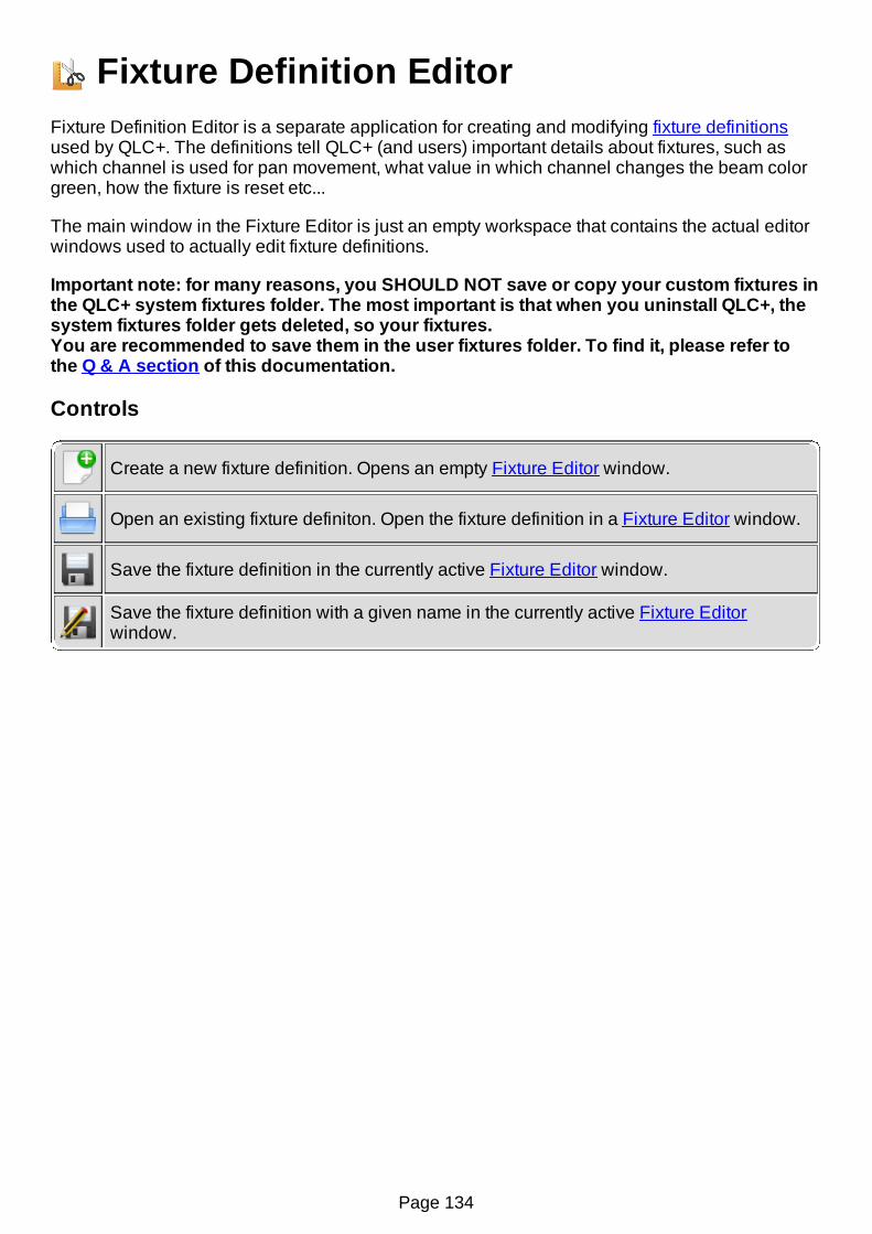
Fixture Definition EditorFixture Definition Editor is a separate application for creating and modifying fixture definitionsused by QLC+. The definitions tell QLC+ (and users) important details about fixtures, such aswhich channel is used for pan movement, what value in which channel changes the beam colorgreen, how the fixture is reset etc...
The main window in the Fixture Editor is just an empty workspace that contains the actual editorwindows used to actually edit fixture definitions.
Important note: for many reasons, you SHOULD NOT save or copy your custom fixtures inthe QLC+ system fixtures folder. The most important is that when you uninstall QLC+, thesystem fixtures folder gets deleted, so your fixtures.You are recommended to save them in the user fixtures folder. To find it, please refer tothe Q & A section of this documentation.
Controls
Create a new fixture definition. Opens an empty Fixture Editor window.
Open an existing fixture definiton. Open the fixture definition in a Fixture Editor window.
Save the fixture definition in the currently active Fixture Editor window.
Save the fixture definition with a given name in the currently active Fixture Editorwindow.
Page 134

Capability EditorWith the Capability Editor you can define a value range for a certain functionality provided by afixture channel. For example, if values 0-15 produce a white color capability, you might put:
0 to the Min field15 to the Max field, and"White" to the Description field
Controls
Min The minimum value of the capability
Max The maximum value of the capability
Description The name or description of the capability. Don't be too elaborate, just a fewwords will do.
Click & Go capability
The Click & Go functionality for a channel starts from the Capability Editor.When a channels group is set to Gobo, Color or Effect, it is possible to assign the color or apicture that will be displayed by Click & Go on Scene Editor, Simple Desk and Virtual ConsoleSlider.This allows very quick visual feedback, and will avoid you having to remember the meaning ofeach range of values.When a channel can support Click & Go, some additional controls will appear on the right side ofthe Capability Editor, displaying 3 butons and a preview box. Here's the meaning of each one:
Picture...
By clicking on this button you can select a picture for this range of values, to bedisplayed by Click & Go for visual association and quick access
Color By clicking on this button you can select the first color for this range of values. Whenthe first color is set, the 'Second color' button will be enabled. See below.
Secondcolor
When clicking on this button you can select a second color for those cases where afixture supports it. For example, this is quite useful for moving heads whose colorwheels support intermediate positions.
Page 135
Capability WizardCapability Wizard is a handy tool for creating multiple capability value ranges of same size.Usually this applies to fixed colors, gobo indices and various macro channels.
Controls
Start The starting value for new capabilities. Sometimes there might be other capabilitiesat the start of the channel's value range that you can skip by adjusting this value.
Width The size of each value range.
Amount Number of capabilities to create.
Name The common name for each capability. You can use the hash mark # to denote aplace for an index number (i.e. "Gobo #" creates Gobo 1, Gobo 2, Gobo 3...)
Sample Every time you change a parameter in the wizard, this list is updated to show you asample of what kinds of capabilities will be created once you click OK.
Page 136

Channel EditorThe Channel Editor is used to edit individual channels and the DMX value ranges of eachcapability (a green color, a certain gobo, prism rotation, etc..) that a fixture channel provides.Refer to your fixture's manual to get a detailed list of the fixture's channels and DMX values.
Controls
Name The name of the channel
Group
The channel's logical group (its role in the fixture).
Assign a channel to the Intensity group if the channel should obey the HTPrule. Also, the Grand Master controls only Intensity channels by default. Note alsowhen you create RGBAW/CMY channels, that they should be assigned to theIntensity group, and NOT the Color group. The Color Tool in Scene Editor isavailable only if a fixture provides Intensity channels for RGBAW/CMY, whoseColor properties have been set accordingly (see the Color setting below).
Assign a channel to the Color group if the channel controls a fixed color wheelor pre-defined color macros. Don't assign individual RGBAW/CMY color channelsto the Color group but instead use the Intensity group as described above Thechannel obeys the LTP rule.
Assign a channel to the Gobo group if the channel controls gobo wheel positionor indexing. The channel obeys the LTP rule.
Assign a channel to the Speed group if the channel controls something relatedto speed (gobo rotation, rainbow speed, tracking speed). The channel obeys theLTP rule.
Assign a channel to the Prism group if the channel controls a prism. Thechannel obeys the LTP rule.
Assign a channel to the Prism group if the channel controls a prism. Thechannel obeys the LTP rule.
Assign a channel to the Shutter group if the channel controls a shutter or strobe.The channel obeys the LTP rule.
Assign a channel to the Beam group if the channel controls a beam shaper. Thechannel obeys the LTP rule.
Assign a channel to the Effect group if the channel controls something thatdoesn't quite fit into any of the other groups. The channel obeys the LTP rule.
Assign a channel to the Maintenance group if the channel contains fixtureresetting or cooling fan controls or something similar. The channel obeys the LTPrule.
Assign a channel to the Nothing group if the channel should not appear in theScene Editor or Fixture Console.
Assign pan channel(s) to the Pan group and respectively, tilt channel(s) to the
Page 137

Tilt group. See the Control Byte property below. The channel obeys the LTP rule.
Color
Only available when the channel has been assigned to the Intensity group. Itindicates whether the channel controls a specific color out of the primary colorsRed, Green, Blue, Cyan, Magenta, Yellow, Amber, White or UV. If the channelcontrols the fixture's master intensity, the Generic color setting should be used.
ControlByte
Applicable to channel pairs that make 16 bit values, usually Pan or Tilt group, butsome newer fixtures support 16 bit dimmer or even RGB, gobo or focus channels.For 8 bit values (e.g. when the fixture supports only 8bit movement, only onechannel for each movement), assign the Coarse MSB control byte to the channel.If, however, the fixture supports 16bit movement (two channels for eachmovement), or other 16 bit channel, you should assign the Coarse MSB byte tothe channels that provide coarse value and the Fine LSB byte to the channelsthat provide fine value adjustment. If you are not sure, use Coarse MSB.
Capabilitylist
Shows you a list of DMX value ranges for the currently edited channel. If achannel provides only one capability (for example pan or dimmer) the only thingneeded in the list is one capability with a range of 0 to 255. For more elaboratecapabilities, such as colors or gobos, you should create capability ranges for eachof the colors (for example 0-15 white, 16-32 blue...)
Add a new capability to the channel, using the Capability Editor.
Remove the selected capabilities from the channel.
Edit the selected capability, using the Capability Editor.
Create new capabilities quickly with the Capability Wizard.
Page 138

Fixture EditorFixture Editor windows contain everything needed to edit one Fixture Definition at a time. Thewindows are separated in three tabs: General, Channels and Modes.
Controls - General Tab
Manufacturer The fixture's manufacturer name. For example "FooCompany".
Model The fixture's model name. For example "FooZapper 2000".
Type The fixture's generic type.
Controls - Channels Tab
The channels tab contains all possible channels that the fixture understands in all of its modes.The channel order doesn't matter in this tab at all. Instead, channels are arranged in certain orderin each mode in the Mode tab. On the Channel tab, only the channel names, their capabilities(i.e. value ranges and their purpose) matter.
Channellist
Shows all of the channels that the fixture understand in all of its modes. Eachchannel item also shows all of its capabilities in a sub tree.
Add a new channel to the fixture using the Channel Editor.
Remove the selected channels from the fixture and from all modes.
Edit the currently selected channel using the Channel Editor
Copy the currently selected channel to the clipboard. Channels in the clipboard canalso be pasted to other fixture definition windows.
Paste a channel from clipboard to the fixture definition. Channels in the clipboardcan also be pasted to other fixture definition windows.
Open or close all of the channel nodes in the channel list.
Controls - Modes Tab
The modes tab contains all modes the fixture can be configured to.
Modelist
Displays all modes for the currently edited fixture. Each mode item can be opened todisplay the set and order of channels in that mode.
Name: The name of the mode (each name must be unique)Channels: Number of channels in each mode
Create a new mode for the fixture, using the Mode Editor.
Remove the currently selected mode from the fixture. Removing a mode does notdestroy any channels or other modes.
Page 139

Edit the currently selected mode, using the Mode Editor.
Create a copy of the currently selected mode to the same fixture. Since modes aretightly coupled to a certain fixture's channels, modes cannot be copied across fixtures.
Open or close all mode items.
Page 140
Mode EditorThe Mode Editor is used to create and edit modes by picking sets of Channels in certain order(as defined by the fixture's manufacturer). Each editor window is divided into three tabs:Channels, Heads and Physical.
Controls - Channels Tab
In the Channels tab you can place the fixture's channels in an order that forms an actualrepresentation of the DMX channels that the fixture understands when it has been configured inthat particular mode.
ModeName The name of the mode (must be unique for each mode).
Channellist Displays all channels present in the current mode in their proper order.
Add channels from the fixture's channel collection to the mode. You can create/editchannels in the Fixture Editor's Channels tab.When you click on this button a new window will be displayed, showing two lists:
The list on the left shows the channels that have not yet been added to thismode. If you're creating a new mode, this list will show all the channels youcreated in the Fixture Editor's channels tabThe list on the right shows the channels that define the mode you're editing. Ifyou're creating a new mode, this list will be empty.Please note that the order of the channels in this list is fundamental to thefixture mode definition.
To move items from one list to another either use the central buttons or simply dragand drop them.When done, press OK to update the mode channel list.
Remove the selected channels from the mode. Other modes' channel selections areleft untouched.
Raise the selected channel up by one.
Lower the selected channel down by one.
Controls - Heads Tab
In the Heads tab you can define multiple heads for a single fixture, so that QLC+ knows to treateach of them individually in certain situations (such as Fixture Groups). If a fixture contains onlyone head when it's configured to use the currently edited mode (i.e. all of the mode's channelscontrol one head at a time) there is no need to define the head. If, however, the fixture hasmultiple heads that you wish to be able to control, you must define each head here.
Heads don't have names as they can be thought of as simple "sub-fixtures" inside a fixture.Instead, they are automatically given index numbers. The ordering of the Heads should follow thephysical fixture's configuration as closely as possible. So, if the heads go 1, 2, 3, 4 in the realworld, don't define them as 4, 2, 1, 3 or something equally annoying.
Page 141
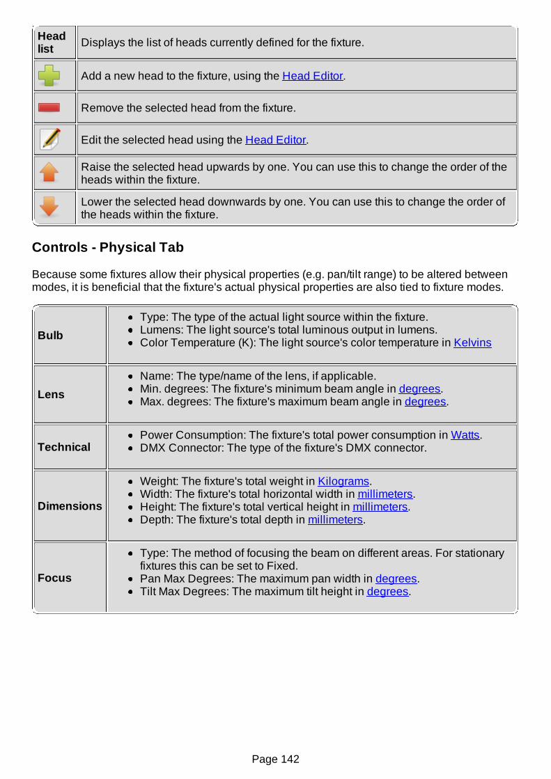
Headlist Displays the list of heads currently defined for the fixture.
Add a new head to the fixture, using the Head Editor.
Remove the selected head from the fixture.
Edit the selected head using the Head Editor.
Raise the selected head upwards by one. You can use this to change the order of theheads within the fixture.
Lower the selected head downwards by one. You can use this to change the order ofthe heads within the fixture.
Controls - Physical Tab
Because some fixtures allow their physical properties (e.g. pan/tilt range) to be altered betweenmodes, it is beneficial that the fixture's actual physical properties are also tied to fixture modes.
BulbType: The type of the actual light source within the fixture.Lumens: The light source's total luminous output in lumens.Color Temperature (K): The light source's color temperature in Kelvins
LensName: The type/name of the lens, if applicable.Min. degrees: The fixture's minimum beam angle in degrees.Max. degrees: The fixture's maximum beam angle in degrees.
TechnicalPower Consumption: The fixture's total power consumption in Watts.DMX Connector: The type of the fixture's DMX connector.
Dimensions
Weight: The fixture's total weight in Kilograms.Width: The fixture's total horizontal width in millimeters.Height: The fixture's total vertical height in millimeters.Depth: The fixture's total depth in millimeters.
Focus
Type: The method of focusing the beam on different areas. For stationaryfixtures this can be set to Fixed.Pan Max Degrees: The maximum pan width in degrees.Tilt Max Degrees: The maximum tilt height in degrees.
Page 142

Head EditorThe Head Editor is used to create and edit heads by picking sets of Channels that are dedicatedto a single head (as defined by the fixture's manufacturer).
Controls
The controls are very simple: place a checkmark on each channel that is used ONLY by the headyou are currently editing. To add a head, see Mode Editor.
Channellist
Displays the list of all fixture channels available in the current mode. Channels thathave been assigned to another head are disabled and cannot be selected becauseeach channel can only belong to one head at a time.
Page 143

Scene tutorialThis tutorial covers just the basic procedure of creating a fixture, a scene and a button and how tomake them work. The point is to give the user a quick yet complete here-hold-my-hand-experience on how the Q Light Controller Plus is planned to work as a software for DMX lightingautomation.
Before you start reading this tutorial, please familiarise yourself with the Main window and itsparts.
Now we can really start!
Fixture Manager
Open the fixture manager panel now by clicking its icon.
The fixture manager is the heart of QLC+ fixture-oriented architecture. As its name implies, youcan manage (add, remove and edit) your lighting fixtures from the fixture manager. On the lefthand side of the manager there is a list that contains all of the fixtures in the current workspace(at the moment it will be empty). On the right hand side you can see some information related tothe currently selected fixture. On the top of the fixture manager there is again another toolbar,containing the following buttons (from left to right):
Add new fixtures
Remove selected fixtures
Configure the selected fixture
Group a fixture selection
Ungroup a fixture from a group
Import a previously saved list of fixtures
Export a list of fixtures
Adding a fixture
Add a fixture to the workspace by clicking the add button.
On the left side of the dialog you can see a list of available fixture manufacturers. Eachmanufacturer's name is actually a folder containing a number of different fixture models producedby that manufacturer. You can find, for example, a "DJScan250" under the "Futurelight" folder. Asyou click a fixture from the list, you can see the Channels field on the right hand side change todisplay the number of DMX channels required by the selected fixture. There's also a list of thefixture's channels just under the Channels box.
Go ahead and select Futurelight DJScan250 but don't click OK just yet.
You can edit the new fixture's name in the Name field or you can stick to the default that theapplication suggests. If the fixture has different operational modes (different sets of channels),you can select one from the Mode box. The DJScan250 doesn't have more than one, so there'sjust "Mode 1" there. The fixture's DMX address can be set in the Address field and should be thesame as the actual physical fixture's DMX address. The Universe field is used to assign thefixture to a physical DMX output universe. Usually each universe has its own cable coming fromthe PC.
If you wish to add multiple fixtures of the same type, you can increase the value in the Amountbox. If you wish to leave some gaps between each fixture's address space, you can change thevalue in the Address gap box. Let's leave these be for now.
If you don't understand the DMX addressing principles, please consult your lighting equipmentmanuals for more information. In short, a DMX address is the first DMX channel of a particularfixture. In the case of a DJScan250 (which uses 6 channels), assigning for example 1 as its DMXaddress, reserves channels 1, 2, 3, 4, 5, and 6 for the fixture. The next fixture must then beassigned to DMX address 7 to prevent channel overlapping. Let's use address 1 now.
Back to the fixture managerClick OK to close the dialog and add one Futurelight DJScan250 to the workspace.
Page 144

On the left side of the fixture manager you can now see the fixture that we just added. On the rightside, you can see the information about the fixture. You can edit the fixture's name, address anduniverse by clicking the Configure button. You can also change the fixture definition through theconfiguration dialog, but since we're quite happy with the fixture's information, we are not goinggo there.
My first function
Open the function manager by clicking its button on the main toolbar
If the fixture manager was the heart, function manager must be the brain of QLC+. With it, you canadd, remove and edit various functions that perform the actual light automation for you. Let's lookat the view first. There is, once again, a toolbar containing the following icons (from left to right):
Add a scene
Add a chaser
Add a sequence
Add an EFX
Add a collection
Add a RGB matrix
Add a script
Page 145
Open the Functions wizard
Copy the selected functions
Destroy the selected functions
Below the toolbar, there is a list of functions within the current workspace. Since we haven't yetcreated any, it's still empty.
Scene editor
Add a new scene to the workspace by clicking the scene button
With the scene editor, you can create scene functions that basically contain values for a numberof channels that relate to certain fixtures. On the left hand side of the editor there is a list offixtures used in the scene, which is empty (but not for much longer). There are also some buttonsto add/remove fixtures and enable/disable all the selected fixtures channels.On the right hand side of the editor there is a list of channel groups used in the scene. Channelgroups will not be used in this tutorial.
Add a fixture to the scene by clicking the add button. Select our one and only fixture,
the DJScan250 from the list that pops up and click the OK button.
Now the scene has one fixture to control. Notice also that now there is new tab just beside theGeneral tab with our fixture name. Click the tab that says DJScan250.
Now you can see a panel with 6 sliders & buttons, each of them representing a channel withinthe fixture, but all of the channels are disabled. Above each of the buttons (the ones with icons)there is yet another box which, when checked, enables the corresponding channel in the scene.If a box is not checked, that channel will not be touched by the scene at all. This is very usefulwhen you wish to create for example a function that just sets the color of a scanner, withouttouching the gobo, intensity, pan, tilt and other features that you might wish to stay the way theyare.
Set channels 3, 4 and 6 enabled by clicking on their check boxes.
You'll see that channels 3 and 4 changed their appearance and are no longer grayed out. Youcan also move their sliders and click their buttons. When you click on a button, you get a list ofavailable capabilities that the fixture can do when a certain value is set to the channel. In thecase of a DJScan250, channel 3 controls the color wheel, channel 4 controls gobo selection andchannel 6 controls the fixture's shutter.
If you click the button on channel 3, you get a list of available colors that the fixture supports.Since many of these capabilities are specified by the manufacturer as a value range rather than asingle value, many of these capabilities contain yet another sub-menu. Let's try setting a color.
Click the color button on channel 3, then move your cursor to "Orange" and select
"80" from the sub-menu by clicking on that value.
Notice that the slider on channel 3 also moved up and the value above it now shows 80. If youhave already patched an output plugin to the first universe, you may already see some actiongoing on with your DMX equipment, since the scene editor also sends real DMX data to yourfixtures as you edit the values. If you haven't done any mappings, don't feel bad, we'll get to it.
Next, click the gobo button and choose "Gobo 7", value 126 and then click the
intensity button and choose "Shutter open", value 255.
Now we have a scene function that sets the value of DJScan250's channel 3 to 80, channel 4 to126 and channel 6 to 255. Now all we need is a nice descriptive name for the scene. Click theGeneral tab to go to the general page where we started with the scene editor.
You can set a nice name to the scene by writing it to the Scene name edit box. Type:"DJScan250 Orange Gobo 7" there.
Now we're going to set a Fade In time to the Scene, so that when we play it it will fade to thevalues we set in a given amount of time.Click on the icon from the Scene Editor toolbar. A tool will be displayed, allowing you to
choose the Fade In and Fade Out times of the Scene. Let's change Fade In to 5 seconds. Eitheruse the speed dial widget or manually write '5' on the second last text field where 0s is written.
Page 146
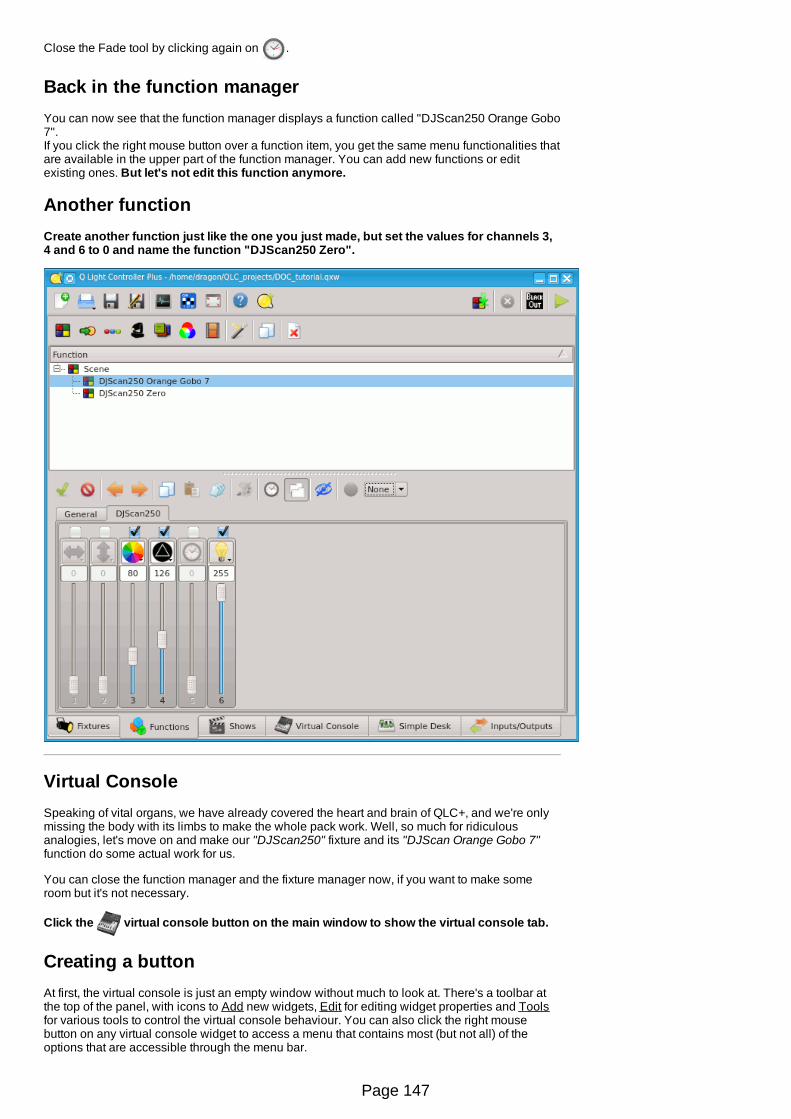
Close the Fade tool by clicking again on .
Back in the function managerYou can now see that the function manager displays a function called "DJScan250 Orange Gobo7".If you click the right mouse button over a function item, you get the same menu functionalities thatare available in the upper part of the function manager. You can add new functions or editexisting ones. But let's not edit this function anymore.
Another functionCreate another function just like the one you just made, but set the values for channels 3,4 and 6 to 0 and name the function "DJScan250 Zero".
Virtual ConsoleSpeaking of vital organs, we have already covered the heart and brain of QLC+, and we're onlymissing the body with its limbs to make the whole pack work. Well, so much for ridiculousanalogies, let's move on and make our "DJScan250" fixture and its "DJScan Orange Gobo 7"function do some actual work for us.
You can close the function manager and the fixture manager now, if you want to make someroom but it's not necessary.
Click the virtual console button on the main window to show the virtual console tab.
Creating a buttonAt first, the virtual console is just an empty window without much to look at. There's a toolbar atthe top of the panel, with icons to Add new widgets, Edit for editing widget properties and Toolsfor various tools to control the virtual console behaviour. You can also click the right mousebutton on any virtual console widget to access a menu that contains most (but not all) of theoptions that are accessible through the menu bar.
Page 147

Click the icon to add a new Button widget.
An empty button appears to the virtual console.
Attaching a function to the button
Double click on the button or on the icon to bring up the button's configuration
dialog.
From this dialog you can edit the button's properties:
* Set the Button label that is displayed on the button* Attach a Function to the button* Bind a Key combination to act as button presses * Bind the button to an External Input source* Set the Button press behaviour
Click the attach button to open a function selection dialog. Double-click on the
"DJScan250 Orange Gobo 7" function to attach it to this button.
We don't necessarily need a name for the button, but if you feel like giving it one, please do.
Click OK to accept these changes and close the dialog.
A little fine-tuningIf you gave the button some name, you'll notice that it doesn't quite fit and gets trimmed to a rathershort version of the original (unless you gave it a two-letter name). You can resize the button toany size you like by grabbing it from the box on the button's lower-right-hand corner and draggingthe button a little bigger. But hey, let's change the button's color now.
Click on the button again, and then click on the icon. Select an orange-tinted color
from this dialog and click OK.
Now the button should have an orange background color. Move the button a bit to the side so thatthe next button won't appear on top of it. Well, there's no harm in that, it's just an inconvenience -you want to be able to see both buttons, do you not?
Another buttonCreate another button just like the first one, but attach the function "DJScan250 Zero" tothe second button and set the button background color to black and foreground (text)color to white.
Seeing the resultsSince we haven't covered DMX output patching at all, you probably have a dummy output pluginassigned to all output universes and you can't get any real DMX output from your computer. Thisis OK for now. If you're interested in output mapping details, refer to the Output mapping howto.
Click the monitor button on the main application toolbar to bring up the DMX monitor
window.
You should see a bunch of numbers, and the name of our fixture "DJScan250" inside a bar overnumbers 001 - 006. These numbers represent DMX channels and the values below themrepresent those channels' values. Since we're operating on with a dummy output plugin, themonitor is all that we see for now.
Click the mode switch button on the right-hand corner of the main toolbar to switch to
operate mode.
Hold your breath...
Pay close attention to the monitor while you click the buttons on the virtual console (youknow, the one we just created). Do you see some running numbers that gradually gotowards 80 on channel 3, 126 on channel 4 and 255 on channel 6? Nice.
Note that if you click both buttons simultaneously, the result is usually far from what is wanted.You need to stop the previous function by clicking its button once more (so that the button flashesand stays up) to stop the function and then start the other function.
Page 148

Page 149
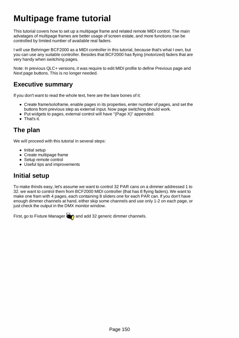
Multipage frame tutorialThis tutorial covers how to set up a multipage frame and related remote MIDI control. The mainadvatages of multipage frames are better usage of screen estate, and more functions can becontrolled by limited number of available real faders.
I will use Behringer BCF2000 as a MIDI controller in this tutorial, because that's what I own, butyou can use any suitable controller. Besides that BCF2000 has flying (motorized) faders that arevery handy when switching pages.
Note: In previous QLC+ versions, it was require to edit MIDI profile to define Previous page andNext page buttons. This is no longer needed.
Executive summaryIf you don't want to read the whole text, here are the bare bones of it:
Create frame/soloframe, enable pages in its properties, enter number of pages, and set thebuttons from previous step as external input. Now page switching should work.Put widgets to pages, external control will have "(Page X)" appended.That's it.
The planWe will proceed with this tutorial in several steps:
Initial setupCreate multipage frameSetup remote controlUseful tips and improvements
Initial setupTo make thinds easy, let's assume we want to control 32 PAR cans on a dimmer addressed 1 to32. we want to control them from BCF2000 MIDI controller (that has 8 flying faders). We want tomake one fram with 4 pages, each containing 8 sliders one for each PAR can. If you don't haveenough dimmer channels at hand, either skip some channels and use only 1-2 on each page, orjust check the output in the DMX monitor window.
First, go to Fixture Manager and add 32 generic dimmer channels.
Page 150

Next things will happen in Virtual console .
Create Multipage frame
The most basic way how to create multipage frame is to create simple frame . Now right-click
on the frame to open context menu, and select "Widget properties" (or press CTRL-E). Go to"Pages" tab. Select "Enable", to enable the multipage functionality. Enter "4" in the "Number ofpages" edit box. Press "OK".
Page 151

Now we'll add the faders for the first page. Add 8 faders one by one. Then click on the
button and do the same for page 2, and again for pages 3 and 4. For each button, open its Widgetproperties, select level mode, and select respective dimmer channel.
Now change to operate mode, and check if the sliders work.
Alternative approach
Page 152

Instead of separately creating sliders for each page, we could create them before enabling pagesand we would select also "clone first page widgets". Then all sliders will be cloned to all pages.
MIDI controlIn the next step, we are going to setup MIDI remote control. In other words, we want to controlswitching of the pages and the sliders from the MIDI controller.
We start in Input/Outputs tab and setting basic MIDI control. Select e.g. universe 2 for MIDIcontrol, choose BCF2000 MIDI 1 port; check both "input" and "feedback", and select BCF2000profile.
Now go to the virtual console, right click the multipage frame, and select "Widget Properties".Select some buttons as external controls for Previous and Next page, either by autodetection, orchoose from the list (Don't forget to disable autodetect for Previous Page when you are settingNext Page, otherwise you will change both!). I use "Button 9 Top" for previous page, and "Button10 TOP" for next page, but you can choose any buttons. Push OK to close the dialog. Now thetwo buttons should work. Try them now to switch the pages.
The last thing to do is to link the sliders in the frame with the BCF faders. Select page 1, andopen properties for every slider on the page, setting external control as usual. The BCF sliderswill have "(Page 1)" appended to them ("82: Slider 1 (Page 1)"). When you are finished with thefirst page, select page 2, and do the same, and then page 3 and 4. Since with BCF200 we haveMIDI feedback, it's not important if we switch pages in QLC+ or on the MIDI controller. Forcontrollers without feedback, it's crucial to use buttons on the controller, otherwise the pages willget out of sync.
Now you can test the sliders from MIDI controller - all of the 32 PAR cans should be controllableusing those 8 faders and 2 buttons.
Tips and tricks
Multipage solo frames
Solo frames work across pages. If you press a button on any page, buttons/widgets on all pageswill et released.
It is not possible (yet?) to set some buttons to select concrete page, e.g.button to select Page 1, another for Page 2, etc.
Page 153
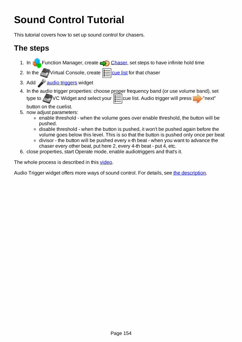
Sound Control TutorialThis tutorial covers how to set up sound control for chasers.
The steps
1. In Function Manager, create Chaser, set steps to have infinite hold time
2. In the Virtual Console, create cue list for that chaser
3. Add audio triggers widget
4. In the audio trigger properties: choose proper frequency band (or use volume band), settype to VC Widget and select your cue list. Audio trigger will press "next"
button on the cuelist.5. now adjust parameters:
enable threshold - when the volume goes over enable threshold, the button will bepushed.disable threshold - when the button is pushed, it won't be pushed again before thevolume goes below this level. This is so that the button is pushed only once per beatdivisor - the button will be pushed every x-th beat - when you want to advance thechaser every other beat, put here 2, every 4-th beat - put 4, etc.
6. close properties, start Operate mode, enable audiotriggers and that's it.
The whole process is described in this video.
Audio Trigger widget offers more ways of sound control. For details, see the description.
Page 154

BCF2000 and LC2412This is small howto to setup remote control with Behringer LC2412 connected through BCF2000.Everything said here is also valid for BCR2000.
With this setup (BCF2000 + LC2412) we get:
8 motorized faders8 turn encoders30 non-motorized faderslots of buttons
That makes a pretty nice console and a much less clicks with mouse :)
Now the steps:
1. Connect MIDI cable from LC2412 MIDI out to MIDI IN on BCF2000. Connect USB cablefrom BCF2000 to the computer.
2. Set BCF2000 to U-2 modePress and hold EDIT and then push STORE.Release both buttons.Turn the leftmost encoder until it shows u-2.Push EXIT button.
3. Start QLC+4. In the INPUT/OUTPUTs tab:
For one universe, choose BCF2000 MIDI 1 port; check both "input" and "feedback",and select BCF2000 profileFor another universe, choose BCF2000 MIDI 2 port; check "input" only - LC2412does not have feedback capability. Choose LC2412 profile.
5. Now you can choose from knobs, faders and buttons of either device for your VC controls.
Page 155

Command-Line ParametersQLC+ supports a number of command line parameters to automate/extend some functionalitieson startup.Using command line parameters can be tricky depending on the operating system you're using:
Linux: just open a terminal and type "qlcplus" followed by the parameters you needWindows: create a shortcut of qlcplus.exe (usually located in C:\QLC+) on your desktop.Right click on the shortcut and select "Properties". In the "Target" field you will seesomething like "C:\QLC+\qlcplus.exe". There you can add command line parameters.When done click OK.
Example: Setting Czech locale:
OSX: This is the most difficult case since QLC+ on OSX is bundled into a DMG package.You need to open a terminal and "cd" into the QLC+ DMG like this:cd QLC+.app\Contents\MacOSWhen done, type "qlcplus" followed by the parameters you need
-c or --closebuttonDescription: Define a position for a close button in the virtual console. The button can be usedto close QLC+. Only has an effect in kiosk mode (see -k) and is most useful when in fullscreenmode without a window manager.
Page 156

Parameters: x,y,w,h
Examples:Create a button at (x400, y500) whose size is (w70, h50):qlcplus -c 400,500,70,50qlcplus --closebutton 400,500,70,50
-d or --debugDescription: Enable debug mode and optionally set the output level. Note that since 4.8.0messages for level DEBUG (0) are not included in released binaries.
Parameters: Level (see QtMsgType)
Examples:Enable debug mode and set debug level to 0:qlcplus -dqlcplus --debug
Enable debug mode and set debug level to 3:qlcplus -d 3
-f or --fullscreenDescription: Start the application in fullscreen mode
Parameters: Method (either 'normal' or 'resize')
Examples:Tell the window manager to give the whole screen space to QLC+:qlcplus -fqlcplus --fullscreenqlcplus -f normalqlcplus --fullscreen normal
Resize QLC+ to take up the whole screen space (useful in custom X11 sessions without awindow manager):qlcplus -f resizeqlcplus --fullscreen resize
-g or --logDescription: Log debug messages to a file ($HOME/QLC+.log)
Parameters: None
Examples:Enable debug messages and store them to log file:qlcplus -d 0 -gqlcplus --debug 0 --log
-h or --helpDescription: Display command-line help (only in Linux & OS X)
Parameters: None
Examples:Page 157
Display the command-line help:qlcplus -hqlcplus --help
-k or --kioskDescription: Enable kiosk-mode (only virtual console is visible and the application is locked inoperate mode)
Parameters: None
Examples:Start the application in kiosk mode:qlcplus -kqlcplus --kiosk
-l or --localeDescription: Use the given locale for translation
Parameters: Locale name (currently supported: ca_ES, cz_CZ, de_DE, en_GB, es_ES, fi_FI,fr_FR, it_IT, ja_JP, nl_NL, pt_BR)
Examples:Use finnish language:qlcplus -l fi_FIqlcplus --locale fi_FI
-m or --nowmDescription: Inform the application that the system doesn't provide a window manager. QLC+will therefore add some extra controls to close the windows.
Parameters: None
Examples:Start QLC+ with no window manager:qlcplus -mqlcplus --nowm
-n or --noguiDescription: Start the application with the GUI hidden (Raspberry Pi only)
Parameters: None
Examples:Start QLC+ with no visible GUI:qlcplus -nqlcplus --nogui
-o or --openDescription: Open the given workspace file
Parameters: File name
Examples:
Page 158

Open mydesk.qxw:qlcplus -o mydesk.qxwqlcplus --open mydesk.qxw
-p or --operateDescription: Start the application in Operate mode.
Parameters: None
Examples:Start QLC+ in operate mode:qlcplus -pqlcplus --operate
-v or --versionDescription: Display the current application version number
Parameters: None
Examples:qlcplus -vqlcplus --version
-w or --webDescription: Enable remote web access on port 9999
Parameters: None
Examples:qlcplus -wqlcplus --web
Page 159

Kiosk ModeQLC+ has a special mode when your lighting needs to be operated by inexperienced people, oryou just want to prevent unwanted changes. It's called the Kiosk mode. In this mode only theVirtual Console is displayed, so no editing is possible.
When you want to start QLC+ in kiosk mode, run:
qlcplus -k -f -o workspace.qxw -p -c 500,10,32,32
-k enables the kiosk mode-f puts QLC+ in fullscreen mode-o workspace.qxw opens specified workspace-p starts operate mode-c 500,10,32,32 creates a close button with size of 32x32 pixels, 500 pixels from left and 10pixels from top.
You can of course specify your own workspace file for -o, and size/position for -c.
You can omit any of the paramteres if you need to - for example, omit -c 500,10,32,32 if you don'twant close button, and omit -f if you don't want fullscreen.
All command-line parameters are described here.
Page 160

Web InterfaceBy default, QLC+ includes a native web server to expose on traditional web browsers some ofthe software features.It comes very handy when you need to run QLC+ on a device without a display (headlesssystem) either to work standalone or for remote controlling.The web interface is not enabled by default but can be easily activated by running QLC+ with "-w" or "--web" option. Please refer to the command line parameters page of this documentation tolearn how to do it.
The web interface can be accessed from any modern web browser running on any device, suchas a computer, a tablet or a smartphone. Your browser needs to support the web socketstechnology to communicate with QLC+, and it is recommended to use Google Chrome.It is also possible to design custom web pages and access QLC+ functionalities via web APIwhich are basically strings formatted in a specific way and sent to QLC+ via websocket.A test page with the available APIs can be found here.
To access the QLC+ web interface simply connect to this address:http://[IP address]:9999
Where [IP address] is the IP address of the device you want to access via web. For example:http://192.168.0.100:9999The web interface consists in three pages:
Virtual ConsoleSimple DeskConfiguration
Virtual Console pageThis page is displayed by default when accessing the web interface address and it representsthe QLC+ Virtual Console.If a project is loaded, this page will display the widgets previously created with QLC+, otherwiseit will just show an empty page.It is possible to load a project with the Load project button placed on the top left corner of thepage. A window will show up, allowing you to choose a file from the device you're using tocontrol the device where QLC+ is running.The project file will be transferred via web and loaded by QLC+.To access the QLC+ configuration page, just click on the Configuration button.
Simple Desk pageThis page is a simplified version of the Simple Desk that you can find in the QLC+ desktopversion. It displays DMX universes divided by pages, where each page shows 32 channels. Youcan switch between pages with the left/right arrow buttons and select the current displayeduniverse with the drop down menu on the top right of the page.It is also possible to reset a universe at once by pressing the reset button (gray X)
DMX Keypad
When clicking on the "DMX Keypad" button in the Simple Desk top bar, you can jump to a newpage where a traditional DMX keypad is displayed.The keypad is useful to set a batch of channel values with a single command. Following a tableexplaining the key commands that you can find on the right side of the pad.
Page 161

explaining the key commands that you can find on the right side of the pad.
Key Description
AT sets a value for a specified DMX channel or group of channels (range).Example: 13 AT 148 (sets channel 13 to value 148)
THRU selects a range of DMX channelsExample: 3 THRU 15 AT 133 (sets channels 3 to 15 to value 133)
FULLsets the maximum value (255) to the selected DMX channels or group of channelsExample: 18 FULL (sets channel 18 to 255)1 THRU 10 FULL (sets channels 1 to 10 to 255)
ZERO sets the minimum value (0) to the selected DMX channels or group of channelsExample: 4 ZERO (sets channel 4 to 0)
BY sets a channels gap within a rangeExample: 1 THRU 10 BY 2 AT 100 (sets channels 1, 3, 5, 7, and 9 to value 100)
+%increases by given percent the current values of the channelsExample: 1 THRU 10 BY 2 +% 20 (increases by 20% the current values of thechannels 1, 3, 5, 7, and 9)
-%reduces by given percent the current values of the channelsExample: 1 THRU 10 BY 2 -% 20 (reduces by 20% the current values of the channels1, 3, 5, 7, and 9)
Please keep in mind that:
Every command is sent to QLC+ only when pressing the ENTER buttonDMX addresses are contiguous between universes, so Universe 1 ranges from 1 to 512,Universe 2 from 513 to 1024 and so onYou can manually write commands in the top text box once you learn the keypadcommands syntax
Configuration pageThis page allows to remotely set the QLC+ configuration, divided in three areas:
Universes configuration: Allows to set the inputs, outputs, feedback, profiles andpassthrough mode for each QLC+ universe. This is basically the same functionality of theQLC+ input/output panel.Since a QLC+ project contains also the I/O information, most likely you won't have tomanually configure it on this page, but just check if everything is correct.Audio configuration: Allows to select the audio devices used for audio playback or audioinput.User loaded fixtures: Allows to remotely load a custom fixture to QLC+.When clicking on the Load fixture button, a window will show up, allowing you to choose afile from the device you're using to control the device where QLC+ is running.The fixture file will be transferred via web and loaded by QLC+.When adding new custom fixtures it is recommended to reload a project or either restartQLC+ on the target device.
Once the configuration has been set, it is possible to go back to the web interface main page byclicking on the Back button, placed at the top left corner of the page.
Page 162

Known limitationsThe QLC+ web interface is still a work in progress feature and it has some known limitations youshould be aware of if you intend to use it.
Speed Dial, XY Pad, Animation and the Clock widgets are not supported yetSliders with a Knob appearance are not supported yetSliders Click & Go button is not supported yetFrames enable state is not handled yetButtons right click to control intesity is not handled yetCue List crossfade sliders not supported yetCue List "Play/Stop + Pause" layout not supported yetCue List notes live editing is not handled yetVirtual Console Grand Master is not handled yet
Page 163

Considered all the issues that have been raised by QLC+ users around this topic, here's anextract of the official FTDI Application Note 134
7 Disabling the Apple-provided VCP on OS X 10.9 and laterA VCP driver for most FTDI USB to serial converters is provided as part of the kernel in OS X10.9 and later. OS X loads this driver (AppleUSBFTDI.kext) when a device with standard FTDIvendor and product identifiers is connected. To use FTDI's own VCP instead, or to use D2XXprograms, AppleUSBFTDI must be disabled, unloaded or blocked, as follows.
7.1 Disable by Renaming (OS X 10.9 and 10.10 only)
Note: this method works only on 10.9 Mavericks and 10.10 Yosemite.
Start a terminal session (Go > Applications > Utilities > Terminal) and copy/paste the followingtext to the command prompt:
cd /System/Library/Extensions/IOUSBFamily.kext/Contents/Pluginssudo mv AppleUSBFTDI.kext AppleUSBFTDI.disabledsudo touch /System/Library/Extensions
then reboot.To re-enable VCP, rename AppleUSBFTDI.disabled back to AppleUSBFTDI.kext
cd /System/Library/Extensions/IOUSBFamily.kext/Contents/Pluginssudo mv AppleUSBFTDI.disabled AppleUSBFTDI.kextsudo touch /System/Library/Extensions
then reboot.
7.2 Temporarily Unload (all versions of OS X)
Note: this method works on all versions of OS X.
It is possible to unload Apple's VCP for the current session, i.e. until the next reboot:
sudo kextunload -b com.apple.driver.AppleUSBFTDI
(If a warning message indicates that the kext can't be unloaded, then reboot and retry the abovecommand.) To reload:
sudo kextload -b com.apple.driver.AppleUSBFTDI
The kextunload and kextload commands can be run in any directory.
7.3 Block with D2xxHelper (OS X 10.9 and later)
Note: this is the only non-temporary method which works on 10.11 El Capitan.
FTDI provides a signed kernel extension (D2xxHelper.kext) which contains no code but acts toprevent OS X from matching an FTDI chip (with standard vendor and product identifiers) with aVCP driver, either Apple's or FTDI's. This leaves the device unclaimed, and available for D2XXprograms only.1. Disconnect all FTDI devices.2. Download and run the D2xxHelper installer from http://www.ftdichip.com/Drivers/D2XX.htm
Page 164

3. Reboot.4. Reconnect the FTDI devices.
Page 165
Parameters tuningThis section explains how to manually get at and tune some QLC+ parameters not available fromthe UI.Keep in mind that if you cannot change them from the UI, it means there is a good reason for it.
Warning: DO NOT edit the configuration files manuallyunless you know what you're doing. Any misplaced changecan cause program crashes or awkward instability.
1 QLC+ configuration locationLinuxConfiguration files are located in your user $HOME directory, in the .config/qlcplus folder.Here's the quick command to access it from a terminal:cd $HOME/.config/qlcplusYou will find both QLC+ and Fixture editor configuration files.
WindowsConfiguration parameters are stored in the Windows registry.To access it, run the "regedit" tool and search for the key named "qlcplus".
Mac OSXConfiguration files are located in your user $HOME directory, in the Library/Preferences folder,which is by default hidden by OSX.Here's the quick command to access it from a terminal:cd $HOME/Library/PreferencesThe QLC+ configuration file is called net.sf.Q Light Controller Plus.plist while the Fixture editorconfiguration file is called net.sf.Fixture Definition Editor.plist.
Please note that preferences are cached ! Basically OSX loads all the plist files in memory atboot, and if you change them manually it will ignore the changes. Even worse, periodically itrefreshes the files, so it overwrites your changes.The solution is, after changing a .plist file, open a terminal and type this:killall -u yourusername cfprefsdWhere yourusername is the name of the user you use to access your Mac. The command forcesOSX to reload the preferences, including your changes.
2 Configuration ResetSometimes it might be necessary to reset the QLC+ configuration and bring QLC+ to a "Factorydefaults" state.To do so, locate the configuration as explained in the first paragraph, then do the following:
On Linux and OSX use the rm 'filename' command to delete the configuration fileOn Windows delete the whole 'qlcplus' KEY using regedit
3 Parameters syntaxDue to Qt differences on different platforms, parameters are stored in different ways dependingon your Operating System.
LinuxParameters are stored in a plain text file that you can modify with a plain text editor like gedit,kwrite, kate, nano, vim or similar. They are presented as follows:
[category] name=value
WindowsParameters are stored in the Windows registry and can be modified with the regedit tool includedin every Windows version. They are presented as follows:
"category" is displayed as a folder "parameter" is contained in "category" and is represented as a key. It is most likely that all QLC+ keys are an integer type. "value" is the actual value of "parameter"
Mac OSXParameters are stored in a plain text file that you can modify with a plain text editor likeTextWrangler or similar. They are presented as follows:
<key>category.name</key> <string>value</string> or <integer>42</integer>
4 Parameters listMost likely you will not find the following parameters in a standard QLC+ configuration. To makethem effective, you need to add them at the end of your configuration file.
4.1 Simple Desk
Category: simpledeskName: channelsperpage
Page 166
Type: integerDescription: Set the number of DMX channel sliders displayed per pageDefault: 32
Category: simpledeskName: playbacksperpageType: integerDescription: set the number of playback sliders displayed per pageDefault: 15
4.2 DMX USB Enttec Open frequency
Category: enttecdmxusbopenName: frequencyType: integerDescription: Set the DMX frame frequency in Hertz for Enttec Open (and similar) devicesDefault: 30
4.3 DMX USB Enttec Open channels number
Category: enttecdmxusbopenName: channelsType: integerDescription: Set the maximum number of DMX channels transmitted by an Enttec Open (and similar) devices.This could solve flickering issues for some cases. For example you might try with 256.Default: 512
4.4 uDMX frequency
Category: udmxName: frequencyType: integerDescription: Set the DMX frame frequency in Hertz for uDMX devicesDefault: 30
4.5 Master Timer frequency
Category: mastertimerName: frequencyType: integerDescription: Set the QLC+ core timer frequency in HertzDefault: 50
Page 167

GUI style customizationStarting from version 4.5.0, QLC+ can read a user custom file to change the GUI appearance in avery accessible way.If no file is found, QLC+ will start with the default style.
The GUI style fileThe file name is hardcoded into QLC+ and must be: qlcplusStyle.qssThe style file must also be placed in a specific path which is:
Linux: $HOME/.qlcplusWindows: Your user folder/QLC+OSX: Library/Application Support/QLC+
The style file must have a CSS syntax. If you're comfortable with web designing, you should findthe creation of this file very easy !Since the style file is strictly related to the inner Qt objects, you might want to read the followingarticles to find out the elements' names and the additional CSS properties the Qt team added tothe default CSS syntax.Qt Style SheetsQt Style Sheets ExamplesIt is up to your imagination how you prefer to customize the QLC+ GUI appearance! If you find astyle worth sharing, don't forget to send in your contribution by posting it online in the QLC+ forum
QLC+ dark blue style exampleJust to give you an example of how easy this process is, here's a blue-ish dark style for QLC+.If you copy the following lines into qlcplusStyle.qss in the right location as explained above, youwill see it immediately applied to QLC+.
QMainWindow, QDialog{ background-color: #404B57; color: #E6E6E6; }
QTreeWidget { background-color: #3A444F; alternate-background-color: #404B57; color: #E6E6E6; }
QTextBrowser { background-color: #3A444F; color: #E6E6E6; }
Page 168