
Pyroelectric PZT sensors screen printed on glasscharlot/pres/pyr.pdfPyroelectric PZT sensors screen...
15
Pyroelectric PZT sensors screen printed on glass Benoît CHARLOT, Denis COUDOUEL, Philippe COMBETTE, Alain GIANI IES Institut d’Electronique du Sud CNRS Université Montpellier II Place E. Bataillon, 34095 Montpellier 7 France DTIP 2013 1
Transcript of Pyroelectric PZT sensors screen printed on glasscharlot/pres/pyr.pdfPyroelectric PZT sensors screen...
Pyroelectric PZT sensors screen printed on glass
Benoît CHARLOT, Denis COUDOUEL, Philippe COMBETTE, Alain GIANI
IES Institut d’Electronique du Sud CNRS Université Montpellier II
Place&E.&Bataillon,&34095&Montpellier&7&France&
DTIP 2013
1&
Outline
Introduction Pyroelectrics Screen Printing PZT sensor Poling
Pyroelectric characterization Piezo
Thermal loading Water Jet Microfluidic
Conclusions
2&
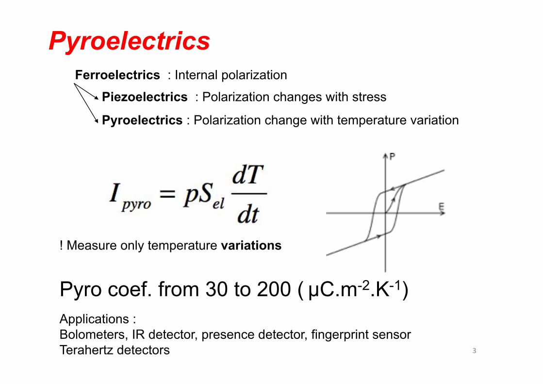
Pyroelectrics Ferroelectrics : Internal polarization
Piezoelectrics : Polarization changes with stress
Pyroelectrics : Polarization change with temperature variation
! Measure only temperature variations
Pyro coef. from 30 to 200 ( µC.m-2.K-1) Applications : Bolometers, IR detector, presence detector, fingerprint sensor Terahertz detectors 3&
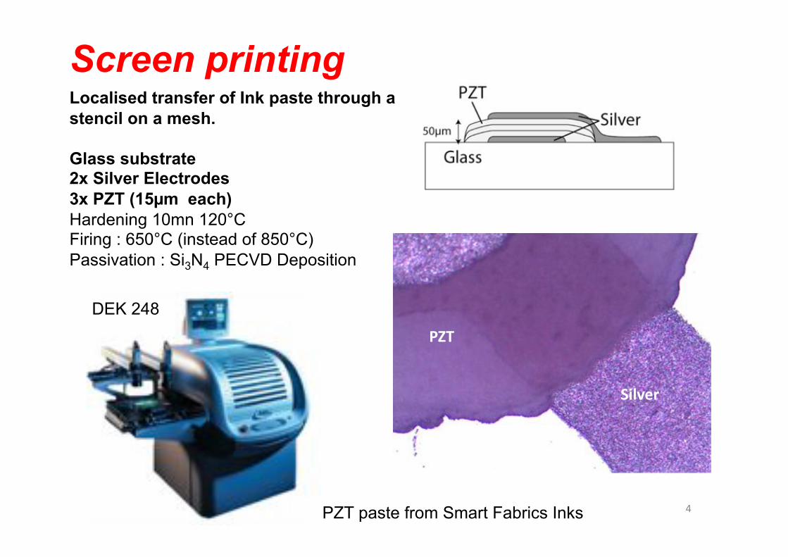
Screen printing Localised transfer of Ink paste through a stencil on a mesh.
Glass substrate 2x Silver Electrodes 3x PZT (15µm each) Hardening 10mn 120°C Firing : 650°C (instead of 850°C) Passivation : Si3N4 PECVD Deposition
DEK 248
PZT paste from Smart Fabrics Inks
PZT$
Silver$
4&
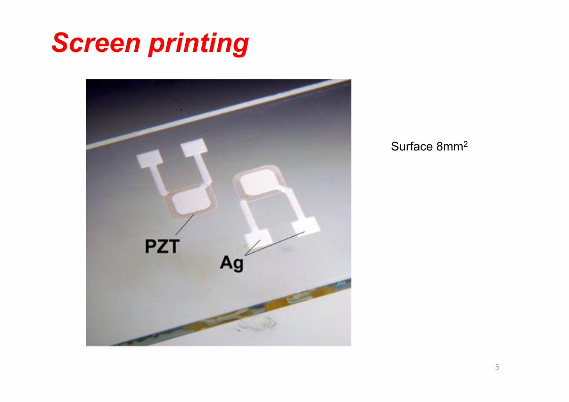
Screen printing
Surface 8mm2
5&
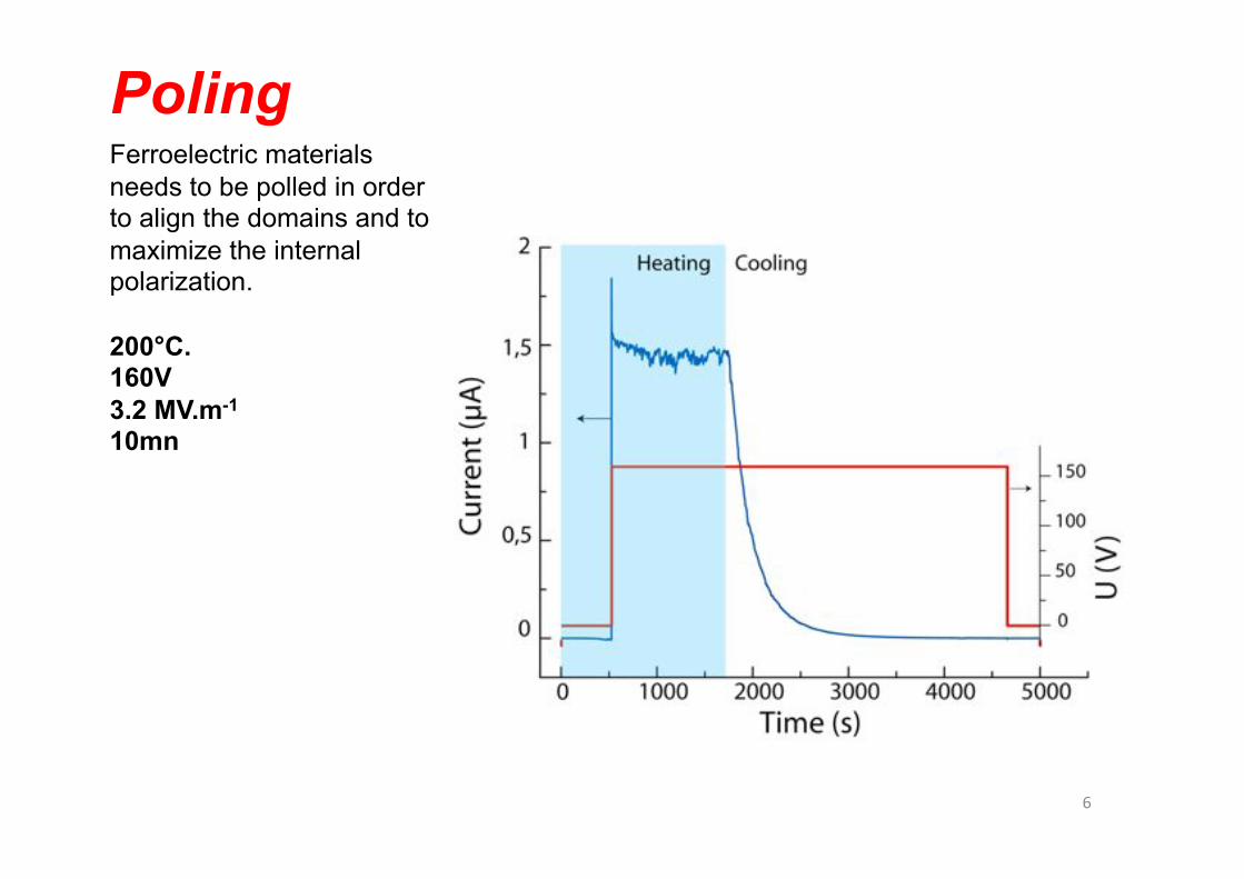
Ferroelectric materials needs to be polled in order to align the domains and to maximize the internal polarization.
200°C. 160V 3.2 MV.m-1 10mn
Poling
6&
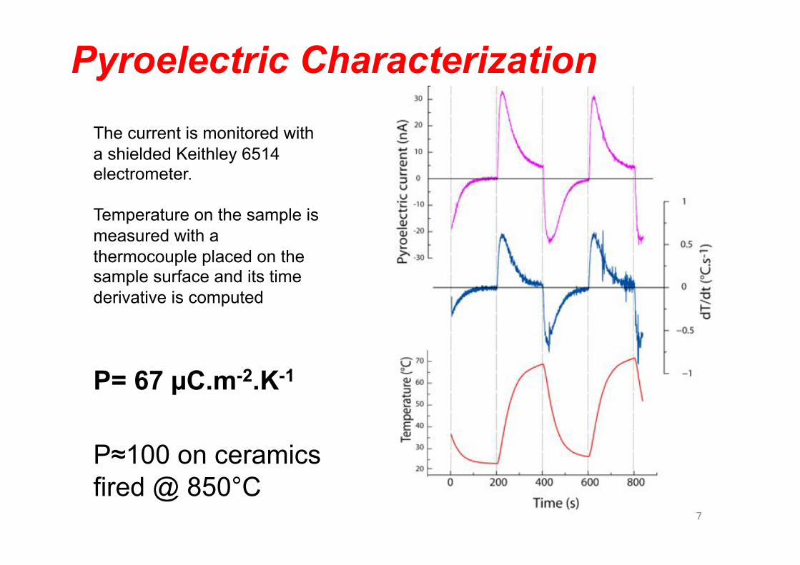
Pyroelectric Characterization
The current is monitored with a shielded Keithley 6514 electrometer.
Temperature on the sample is measured with a thermocouple placed on the sample surface and its time derivative is computed
P= 67 µC.m-2.K-1
P≈100 on ceramics fired @ 850°C
7&
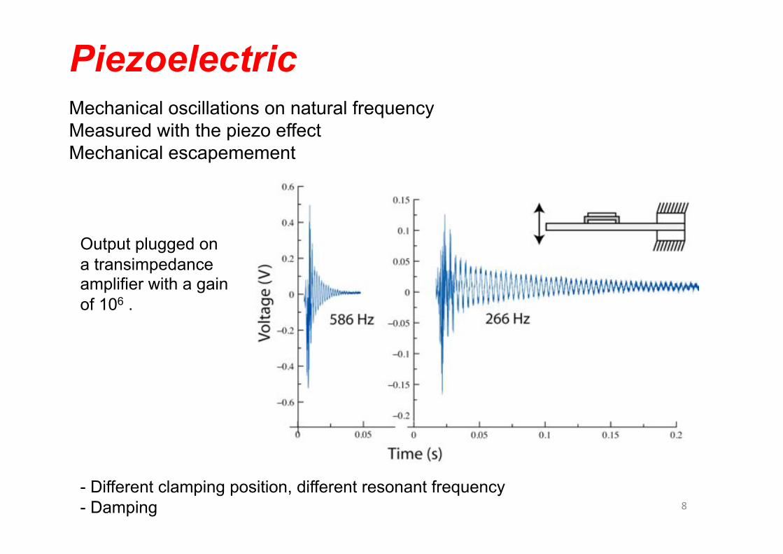
Piezoelectric Mechanical oscillations on natural frequency Measured with the piezo effect Mechanical escapemement
- Different clamping position, different resonant frequency - Damping
Output plugged on a transimpedance amplifier with a gain of 106 .
8&
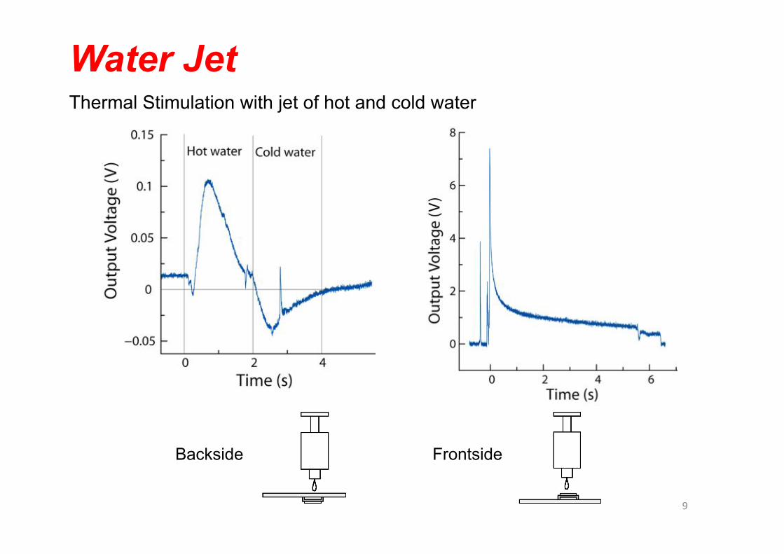
Water Jet Thermal Stimulation with jet of hot and cold water
Backside Frontside
9&
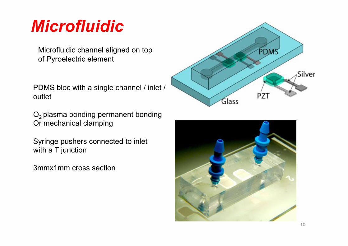
Microfluidic
PDMS bloc with a single channel / inlet /outlet
O2 plasma bonding permanent bonding Or mechanical clamping
Syringe pushers connected to inlet with a T junction
3mmx1mm cross section
Microfluidic channel aligned on top of Pyroelectric element
10&
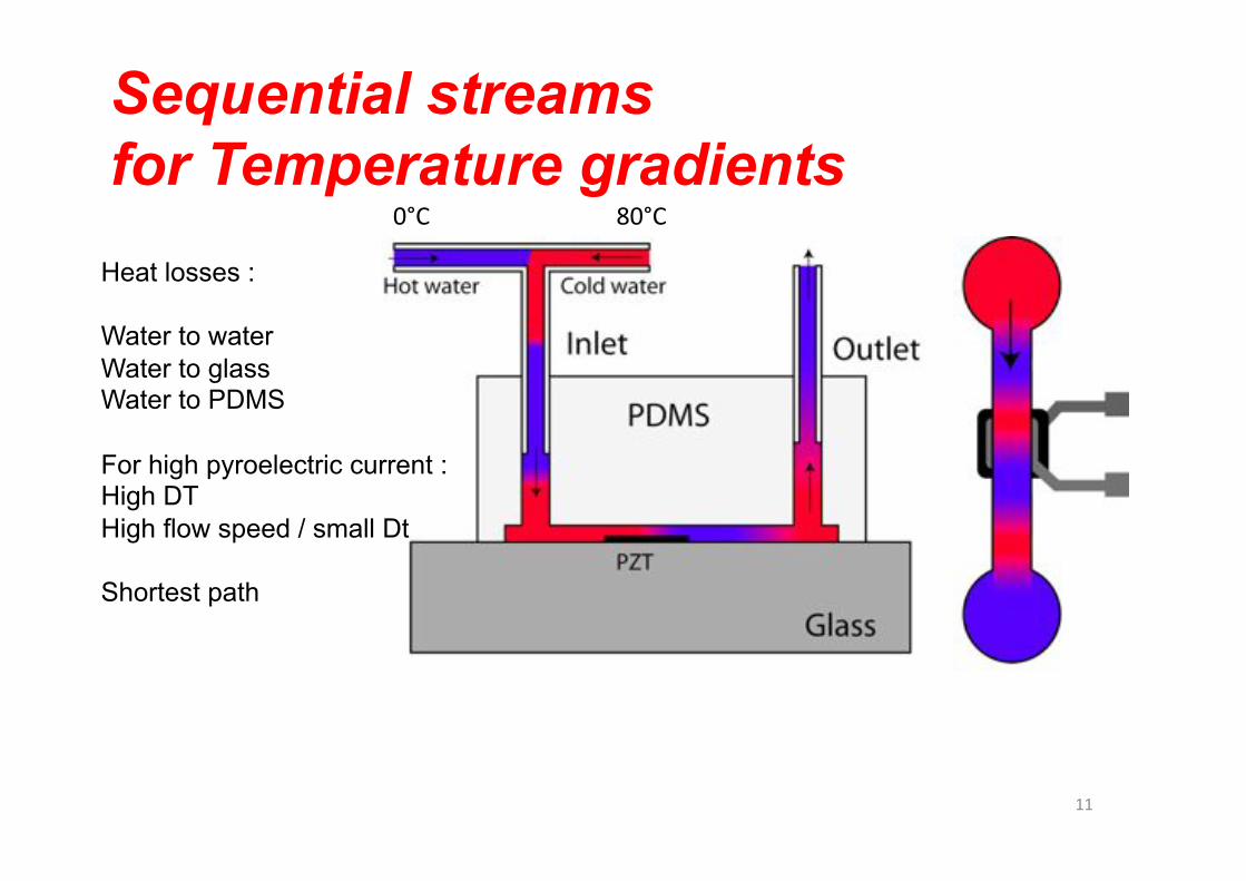
Sequential streams for Temperature gradients
Heat losses :
Water to water Water to glass Water to PDMS
For high pyroelectric current : High DT High flow speed / small Dt
Shortest path
0°C& 80°C&
11&
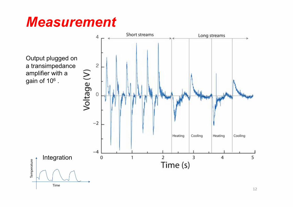
Measurement
Output plugged on a transimpedance amplifier with a gain of 106 .
Integration
12&
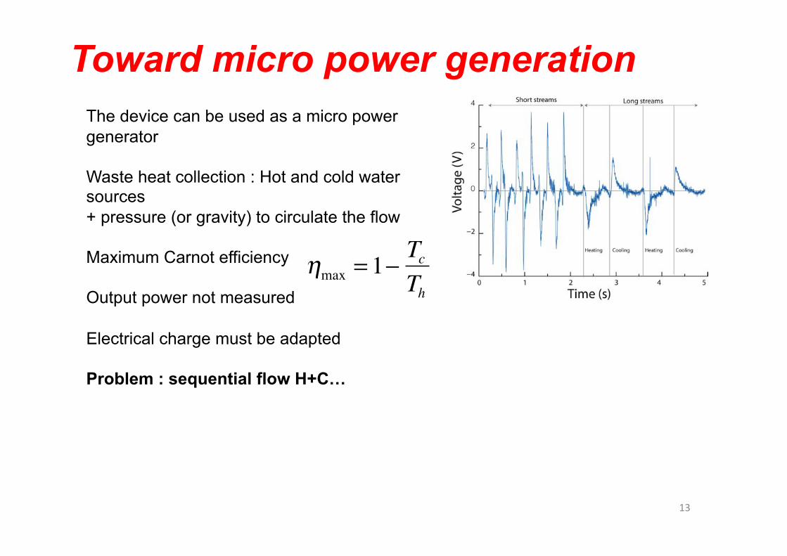
Toward micro power generation
�
ηmax = 1−TcTh
The device can be used as a micro power generator
Waste heat collection : Hot and cold water sources + pressure (or gravity) to circulate the flow
Maximum Carnot efficiency
Output power not measured
Electrical charge must be adapted
Problem : sequential flow H+C…
13&
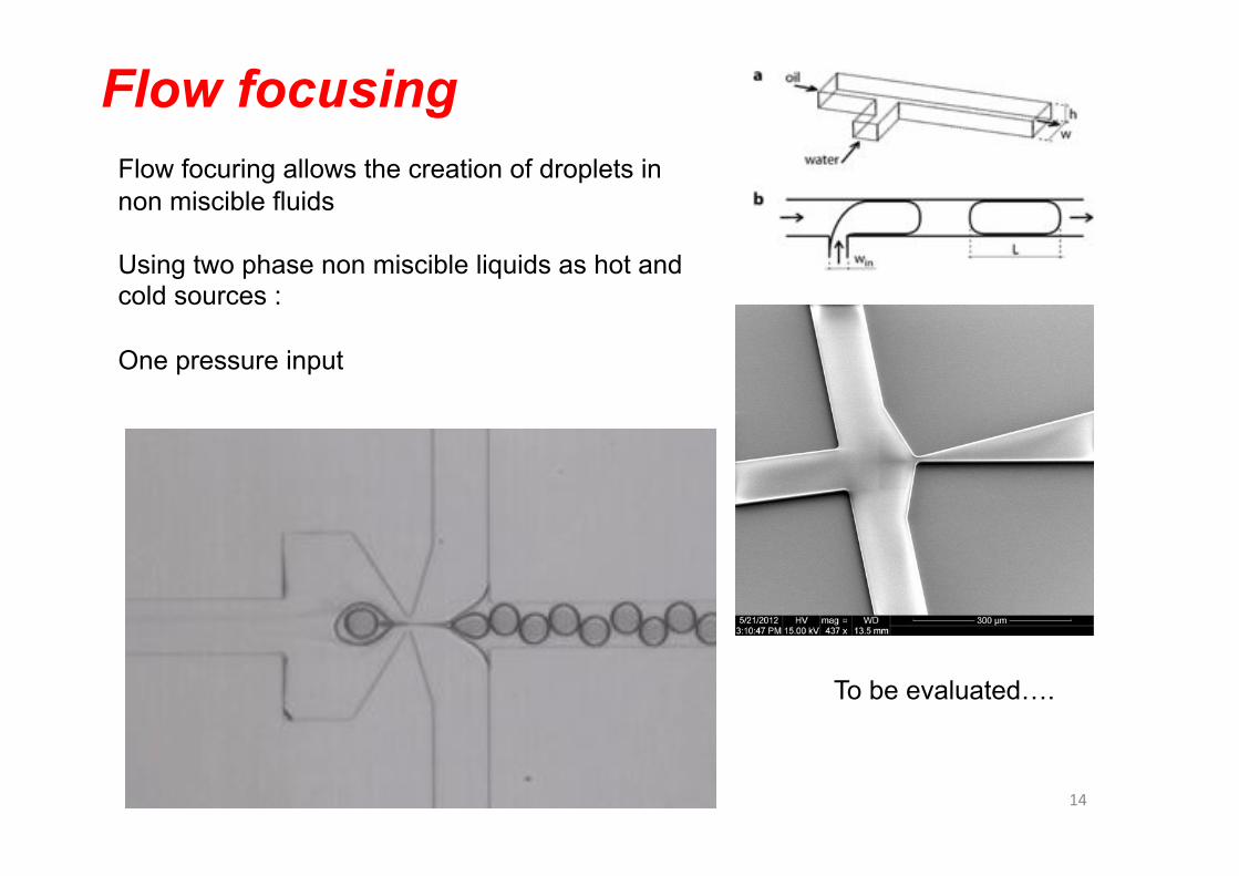
Flow focusing Flow focuring allows the creation of droplets in non miscible fluids
Using two phase non miscible liquids as hot and cold sources :
One pressure input
To be evaluated….
14&
Conclusions
PZT thick film screen printed on glass
Pyroelectric and Piezoelectric behaviour
Streams of consecutive hot and cold water fed through a microfluidic channel
Positive and negative pulses -> pyroelectric current
Potential use in waste heat micro power generation
Optimisation : Material coefficient Substrate (losses) non miscible liquids (one pressure source)
15&