Pyramid of Arclength Descriptor for Generating Collage …ttwong/papers/pad/pad_lowres.pdf ·...
12
Pyramid of Arclength Descriptor for Generating Collage of Shapes Kin Chung Kwan 1,2 Lok Tsun Sinn 1,2 Chu Han 1,2 Tien-Tsin Wong 1,2 Chi-Wing Fu 1 1 The Chinese University of Hong Kong * 2 Shenzhen Research Institute, The Chinese University of Hong Kong Figure 1: “Icons in PAD”: a collage of shapes generated with our scale- and rotation-invariant shape descriptor, namely pyramid of arclength descriptor (PAD); this novel descriptor improves the shape-matching efficiency, thus facilitating the generation of complex results. Abstract This paper tackles a challenging 2D collage generation problem, focusing on shapes: we aim to fill a given region by packing irreg- ular and reasonably-sized shapes with minimized gaps and over- laps. To achieve this nontrivial problem, we first have to analyze the boundary of individual shapes and then couple the shapes with partially-matched boundary to reduce gaps and overlaps in the col- lages. Second, the search space in identifying a good coupling of shapes is highly enormous, since arranging a shape in a collage in- volves a position, an orientation, and a scale factor. Yet, this match- ing step needs to be performed for every single shape when we pack it into a collage. Existing shape descriptors are simply infea- sible for computation in a reasonable amount of time. To overcome this, we present a brand new, scale- and rotation-invariant 2D shape descriptor, namely pyramid of arclength descriptor (PAD). Its for- mulation is locally supported, scalable, and yet simple to construct and compute. These properties make PAD efficient for perform- ing the partial-shape matching. Hence, we can prune away most search space with simple calculation, and efficiently identify candi- date shapes. We evaluate our method using a large variety of shapes with different types and contours. Convincing collage results in terms of visual quality and time performance are obtained. Keywords: Image collage, 2D shapes, Tiling, Shape descriptor, Scale-invariant, Partial-shape matching Concepts: •Computing methodologies → Non-photorealistic rendering; Shape analysis; ∗ e-mail:{kckwan,ltsinn,chan,ttwong,cwfu}@cse.cuhk.edu.hk Permission to make digital or hard copies of all or part of this work for personal or classroom use is granted without fee provided that copies are not made or distributed for profit or commercial advantage and that copies bear this notice and the full citation on the first page. Copyrights for components 1 Introduction Collage is a form of visual art created by pasting elements like pho- tos, clippings, and ribbons onto a canvas region. It exists in several forms, e.g., mosaics, which are made up of colored glass and stone, and photomontages, which cut and compose photographs. In this paper, we focus on generating collages composed of shapes, with- out much consideration of the color. Our goal is to pack 2D shapes to fill a canvas with minimized overlaps and gaps in-between the shapes (e.g., Fig. 2). This form of collage is extensively used in commercial advertisement, 2D design, and many other illustrations. During the design, artists pack each shape one-by-one in a trial- and-error manner, by trying various scale, position, and orientation of this work owned by others than ACM must be honored. Abstracting with credit is permitted. To copy otherwise, or republish, to post on servers or to redistribute to lists, requires prior specific permission and/or a fee. Request permissions from [email protected]. c 2016 ACM. SA ’16 Technical Papers, December 05-08, 2016, Macao ISBN: 978-1-4503-4514-9/16/12 DOI: http://dx.doi.org/10.1145/2980179.2980234 Figure 2: Examples: collages designed by artists, courtesy of Post- master General of Hongkong Post (left) and lalan (right).
Transcript of Pyramid of Arclength Descriptor for Generating Collage …ttwong/papers/pad/pad_lowres.pdf ·...
Pyramid of Arclength Descriptor for Generating Collage of Shapes
Kin Chung Kwan1,2 Lok Tsun Sinn1,2 Chu Han1,2 Tien-Tsin Wong1,2 Chi-Wing Fu1
1The Chinese University of Hong Kong∗
2Shenzhen Research Institute, The Chinese University of Hong Kong
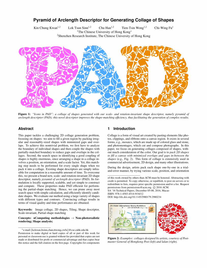
Figure 1: “Icons in PAD”: a collage of shapes generated with our scale- and rotation-invariant shape descriptor, namely pyramid ofarclength descriptor (PAD); this novel descriptor improves the shape-matching efficiency, thus facilitating the generation of complex results.
Abstract
This paper tackles a challenging 2D collage generation problem,focusing on shapes: we aim to fill a given region by packing irreg-ular and reasonably-sized shapes with minimized gaps and over-laps. To achieve this nontrivial problem, we first have to analyzethe boundary of individual shapes and then couple the shapes withpartially-matched boundary to reduce gaps and overlaps in the col-lages. Second, the search space in identifying a good coupling ofshapes is highly enormous, since arranging a shape in a collage in-volves a position, an orientation, and a scale factor. Yet, this match-ing step needs to be performed for every single shape when wepack it into a collage. Existing shape descriptors are simply infea-sible for computation in a reasonable amount of time. To overcomethis, we present a brand new, scale- and rotation-invariant 2D shapedescriptor, namely pyramid of arclength descriptor (PAD). Its for-mulation is locally supported, scalable, and yet simple to constructand compute. These properties make PAD efficient for perform-ing the partial-shape matching. Hence, we can prune away mostsearch space with simple calculation, and efficiently identify candi-date shapes. We evaluate our method using a large variety of shapeswith different types and contours. Convincing collage results interms of visual quality and time performance are obtained.
Keywords: Image collage, 2D shapes, Tiling, Shape descriptor,Scale-invariant, Partial-shape matching
Concepts: •Computing methodologies → Non-photorealisticrendering; Shape analysis;
∗e-mail:{kckwan,ltsinn,chan,ttwong,cwfu}@cse.cuhk.edu.hk
Permission to make digital or hard copies of all or part of this work for
personal or classroom use is granted without fee provided that copies are not
made or distributed for profit or commercial advantage and that copies bear
this notice and the full citation on the first page. Copyrights for components
1 Introduction
Collage is a form of visual art created by pasting elements like pho-tos, clippings, and ribbons onto a canvas region. It exists in severalforms, e.g., mosaics, which are made up of colored glass and stone,and photomontages, which cut and compose photographs. In thispaper, we focus on generating collages composed of shapes, with-out much consideration of the color. Our goal is to pack 2D shapesto fill a canvas with minimized overlaps and gaps in-between theshapes (e.g., Fig. 2). This form of collage is extensively used incommercial advertisement, 2D design, and many other illustrations.
During the design, artists pack each shape one-by-one in a trial-and-error manner, by trying various scale, position, and orientation
of this work owned by others than ACM must be honored. Abstracting with
credit is permitted. To copy otherwise, or republish, to post on servers or to
redistribute to lists, requires prior specific permission and/or a fee. Request
permissions from [email protected]. c© 2016 ACM.
SA ’16 Technical Papers, December 05-08, 2016, Macao
ISBN: 978-1-4503-4514-9/16/12
DOI: http://dx.doi.org/10.1145/2980179.2980234
Figure 2: Examples: collages designed by artists, courtesy of Post-master General of Hongkong Post (left) and lalan (right).
of the shape. Obviously, the search space is enormous. Currently,such collages are manually created; we are not aware of any auto-matic algorithm that can achieve the task within a tractable periodof time. To ease the difficulty in matching/coupling shapes and en-hance the visual pleasantness, artists usually include padding in-between shapes and insert tiny shapes to avoid oversized emptyspace, e.g., the small stars and sector shapes in right sub-figureof Fig. 2. In this paper, we present an automatic method to effi-ciently address this challenging shape packing problem. Note thatour packing problem is not the same as the standard packing prob-lem in geometry, which ignores object changes and scaling.
Existing collage-related methods such as [Hausner 2001; Kim andPellacini 2002; Huang et al. 2011] take a top-down approach ingenerating collages. They divide the canvas into cells and fit shapesinto each cell region, see Fig. 3(a)-(c). Hence, the shapes are im-plicitly assumed to be more-or-less convex with presumed scaleto fit the cells. As a result, their ability in handling more generalshapes and achieving good coupling of shapes is questionable.
On the other hand, we may take a bottom-up approach to progres-sively pack shapes similar to the way artists do. However, this re-quires a highly efficient partial-shape matching process, since everytime we pack a shape into a collage, we have to continuously trans-late, scale and rotate the shape to evaluate the shape coupling, seeFig. 12(c)&(d). This involves an exceedingly large search space: alarge number of candidates (shapes), and for each shape, there canbe unlimited number of instances (each with different scale, loca-tion, and/or orientation). While existing shape descriptors such ascurvature scale space [Mokhtarian and Mackworth 1992; Mokhtar-ian et al. 1996], shape context [Belongie et al. 2002], and triangle-area representation [Alajlan et al. 2007] work well for measuringthe overall similarity between (whole) shapes, they cannot be useddirectly for partial-shape matching. Even we extend them by divid-ing a shape into multiple instances of curve segments for matching,there are exceedingly large choices of segments on each shape, thusleading to a huge search space. Hence, the approach is simply in-feasible for efficient computation (see Section 2 for details).
In this work, we take a bottom-up approach to generate collageswithout assumption nor restriction on shapes and within a tractableamount of time. Given a collection of shapes, our method starts witha seed shape and iteratively fills the given region piece-by-piece,see Fig. 3(d)-(f). In each iteration, we find the best docking loca-tion, orientation, and scale of a shape by maximizing the arclength(which is a partially-matched boundary) shared between the shapeand the current collage. Given N and M as the number of sam-ple points along the boundary of a shape and the current collage,respectively. If we employ an existing shape descriptor to matchinstances of curve segments, we need N2M2 matching tests. Ourkey to tackle the enormous search space within tractable time is anovel shape descriptor, namely pyramid of arclength descriptor (inshort, PAD). Since PAD describes the local shape around a point(locally supported) in a scale- and rotation-invariant fashion, it caneffectively trim down the search space for partial-shape matching,allowing us to perform only NM tests1 to identify the best dock-ing position of a shape onto the collage (see Section 2 for details).Moreover, it has a simple vector form, which is just a sequence ofnormalized arclength values in a pyramidal scale (Section 3), so itis easy to construct and fast to compute.
Unlike existing top-down methods, which produce collages withmore-or-less convex shapes, our method can achieve better shapecoupling, even for arbitrarily irregular shapes, see Fig. 1. By aug-menting the objective function in the shape matching process, we
1If we use a more sophisticated algorithm such as kNN to accelerate, we
can reduce the number of tests to N2logM and N logM , respectively (see
Section 2 for details).
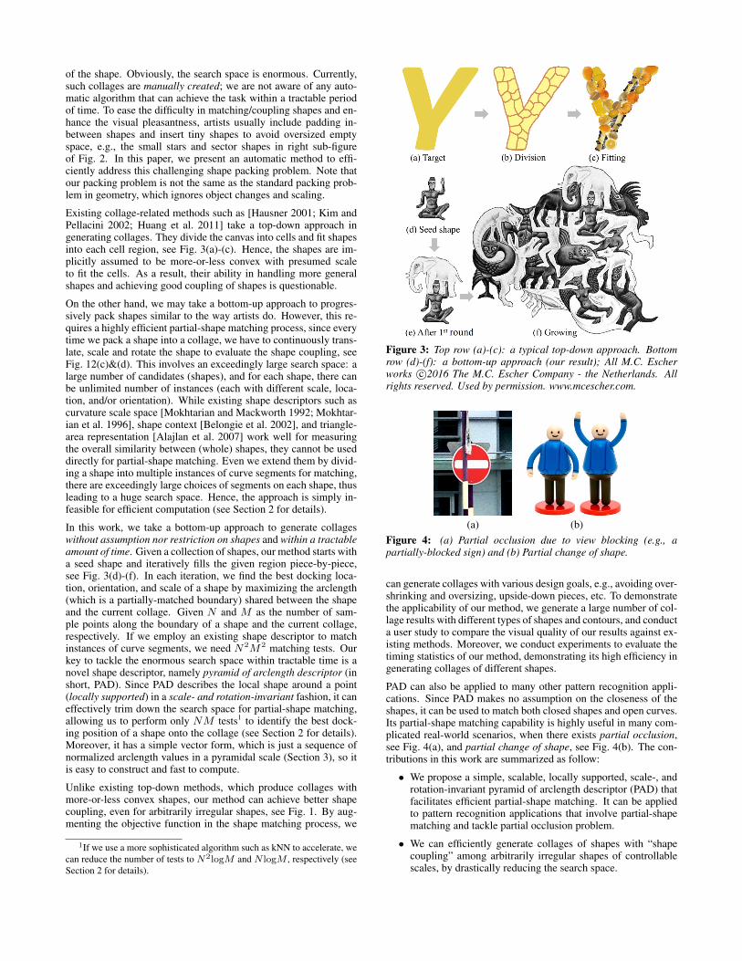
Figure 3: Top row (a)-(c): a typical top-down approach. Bottomrow (d)-(f): a bottom-up approach (our result); All M.C. Escherworks c©2016 The M.C. Escher Company - the Netherlands. Allrights reserved. Used by permission. www.mcescher.com.
(a) (b)
Figure 4: (a) Partial occlusion due to view blocking (e.g., apartially-blocked sign) and (b) Partial change of shape.
can generate collages with various design goals, e.g., avoiding over-shrinking and oversizing, upside-down pieces, etc. To demonstratethe applicability of our method, we generate a large number of col-lage results with different types of shapes and contours, and conducta user study to compare the visual quality of our results against ex-isting methods. Moreover, we conduct experiments to evaluate thetiming statistics of our method, demonstrating its high efficiency ingenerating collages of different shapes.
PAD can also be applied to many other pattern recognition appli-cations. Since PAD makes no assumption on the closeness of theshapes, it can be used to match both closed shapes and open curves.Its partial-shape matching capability is highly useful in many com-plicated real-world scenarios, when there exists partial occlusion,see Fig. 4(a), and partial change of shape, see Fig. 4(b). The con-tributions in this work are summarized as follow:
• We propose a simple, scalable, locally supported, scale-, androtation-invariant pyramid of arclength descriptor (PAD) thatfacilitates efficient partial-shape matching. It can be appliedto pattern recognition applications that involve partial-shapematching and tackle partial occlusion problem.
• We can efficiently generate collages of shapes with “shapecoupling” among arbitrarily irregular shapes of controllablescales, by drastically reducing the search space.
2 Related Work
Collages There are several related computational methods ingenerating 2D collages. Photo collage [Rother et al. 2006; Gofer-man et al. 2010] considers a slightly different problem with thegoal of packing a region with intersecting photos, where the photoboundary can be soft. Puzzle solving methods [Yao and Shao 2003;Goldberg et al. 2004], on the other hand, do not need to considerthe scale of pieces since the sizes of puzzle pieces are fixed.
Kaplan and Salesin [2000; 2004] presents a special type of tilingthat resembles certain artworks of M.C. Escher. Their method mod-ifies a given 2D shape via constrained optimization, so that the mod-ified shape can tile a plane. Dalal et al. [2006] used an FFT-basedcorrelation to generate image collage, but their work only supportsmore-or-less convex shapes. Existing methods for tiling [Hausner2001; Kim and Pellacini 2002; Xu and Kaplan 2007; Orchard andKaplan 2008; Hu et al. 2016; Zou et al. 2016] mostly take a top-down approach, which subdivides the given canvas region into cellsof similar sizes and then fills each cell with a 2D object by maxi-mizing the overall shape similarity. Such 2D object could be a clipart or a photo segment. However, since the subdivision process doesnot consider the shape of the given 2D objects, the tessellated cellsare more-or-less circular in shape and the resulting tiling is less in-teresting with mostly simple and short-length object contacts. Togenerate more irregular cells, Huang et al. [2011] introduced an-other top-down approach that subdivides the canvas region accord-ing to its color. However, their method ignores the shape of thegiven objects, so a good match may not be found for some of thecells. Reinert et al. [2013] presented a framework to perturb 2D ob-jects in the canvas by equalizing the gaps in-between objects. Sincetheir method is not rotation-invariant nor scale-invariant, they can-not pack objects in the collage results with good coupling. Besides2D puzzles, Gal et al. [2007] and Huang et al. [2014] exploredbottom-up approaches to generate 3D collage, but their problemsetting does not require scale invariance.
Compared to previous works, we take a bottom-up approach to gen-erate 2D collages, focusing on packing objects according to shapes.Thanks to the proposed PAD, which enables us to efficiently matchshapes along a partial-shape boundary with scale- and rotation-invariances. We thus can efficiently match and pack shapes into acollage and produce more intriguing results. Without the PAD, thisbottom-up approach would be computationally intractable. This isalso why most previous works do not take a bottom-up approachsince scale invariance needs to be considered during the partial-shape matching process.
Shape Descriptor Two-dimensional shape descriptors can beroughly classified into two categories: global shape descriptors,which describe the overall shape characteristic, and local shape de-scriptors, which describe local shape regions by local features.
Global shape descriptors Typical methods include Hu mo-ments [Hu 1962], Fourier descriptors [Granlund 1972; Persoon andFu 1977], Zernike moments [Khotanzad and Hong 1990], imagemoments [Belkasim et al. 1991; Sheng and Shen 1994], waveletdescriptors [Chuang and Kuo 1996], generic Fourier descrip-tor [Zhang and Lu 2002], and Radon-transform descriptor [Tab-bone et al. 2006]. They compactly describe the characteristics overthe whole shape, so we can efficiently measure overall shape sim-ilarity. However, as they pay more attention to the whole shape,local shape characteristics are usually lost, so they are ineffectivefor partial-shape matching, which focuses on local segments.
To extend global descriptors to support partial-shape matching withscale invariance, we may divide a shape into multiple instances ofcurve segments, describe each instance using a global descriptor,and then perform partial-shape matching by measuring the shape
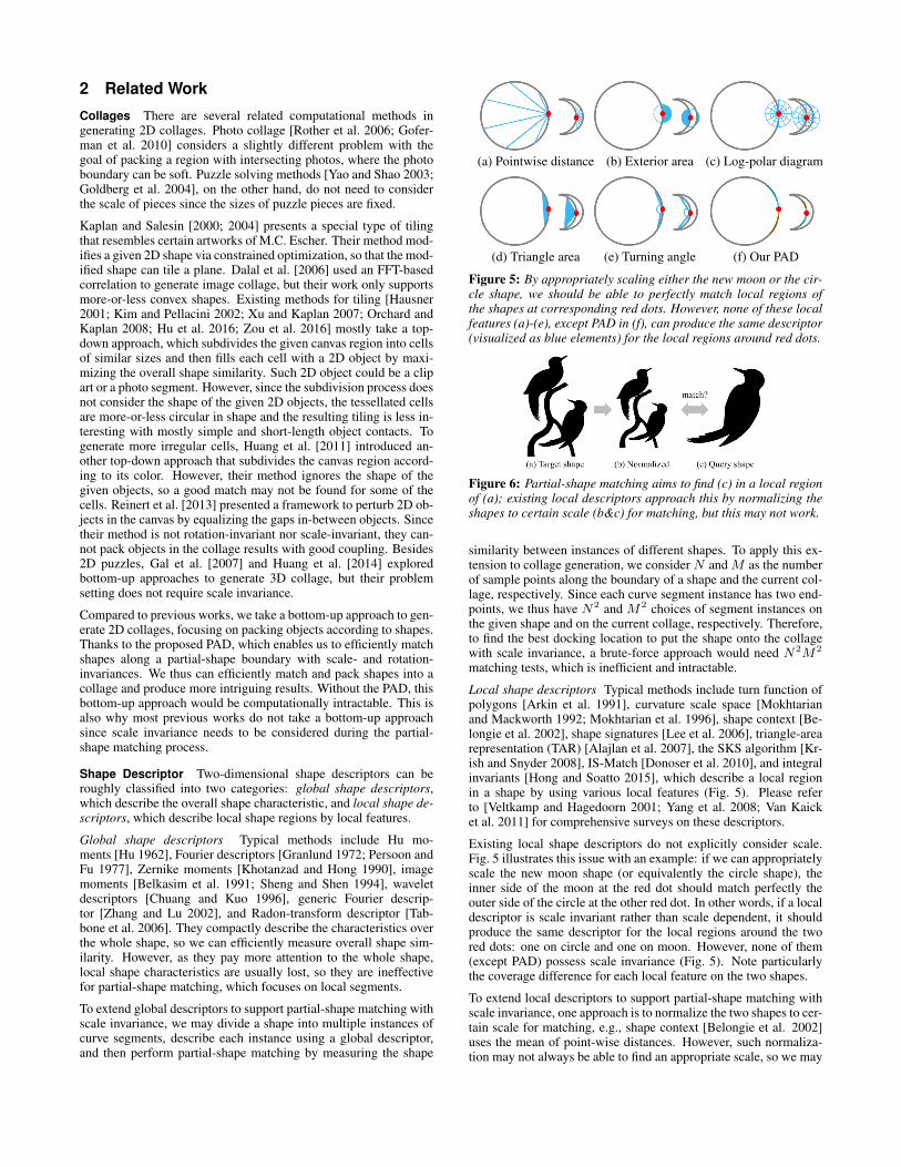
(a) Pointwise distance (b) Exterior area (c) Log-polar diagram
(d) Triangle area (e) Turning angle (f) Our PAD
Figure 5: By appropriately scaling either the new moon or the cir-cle shape, we should be able to perfectly match local regions ofthe shapes at corresponding red dots. However, none of these localfeatures (a)-(e), except PAD in (f), can produce the same descriptor(visualized as blue elements) for the local regions around red dots.
Figure 6: Partial-shape matching aims to find (c) in a local regionof (a); existing local descriptors approach this by normalizing theshapes to certain scale (b&c) for matching, but this may not work.
similarity between instances of different shapes. To apply this ex-tension to collage generation, we consider N and M as the numberof sample points along the boundary of a shape and the current col-lage, respectively. Since each curve segment instance has two end-points, we thus have N2 and M2 choices of segment instances onthe given shape and on the current collage, respectively. Therefore,to find the best docking location to put the shape onto the collagewith scale invariance, a brute-force approach would need N2M2
matching tests, which is inefficient and intractable.
Local shape descriptors Typical methods include turn function ofpolygons [Arkin et al. 1991], curvature scale space [Mokhtarianand Mackworth 1992; Mokhtarian et al. 1996], shape context [Be-longie et al. 2002], shape signatures [Lee et al. 2006], triangle-arearepresentation (TAR) [Alajlan et al. 2007], the SKS algorithm [Kr-ish and Snyder 2008], IS-Match [Donoser et al. 2010], and integralinvariants [Hong and Soatto 2015], which describe a local regionin a shape by using various local features (Fig. 5). Please referto [Veltkamp and Hagedoorn 2001; Yang et al. 2008; Van Kaicket al. 2011] for comprehensive surveys on these descriptors.
Existing local shape descriptors do not explicitly consider scale.Fig. 5 illustrates this issue with an example: if we can appropriatelyscale the new moon shape (or equivalently the circle shape), theinner side of the moon at the red dot should match perfectly theouter side of the circle at the other red dot. In other words, if a localdescriptor is scale invariant rather than scale dependent, it shouldproduce the same descriptor for the local regions around the twored dots: one on circle and one on moon. However, none of them(except PAD) possess scale invariance (Fig. 5). Note particularlythe coverage difference for each local feature on the two shapes.
To extend local descriptors to support partial-shape matching withscale invariance, one approach is to normalize the two shapes to cer-tain scale for matching, e.g., shape context [Belongie et al. 2002]uses the mean of point-wise distances. However, such normaliza-tion may not always be able to find an appropriate scale, so we may
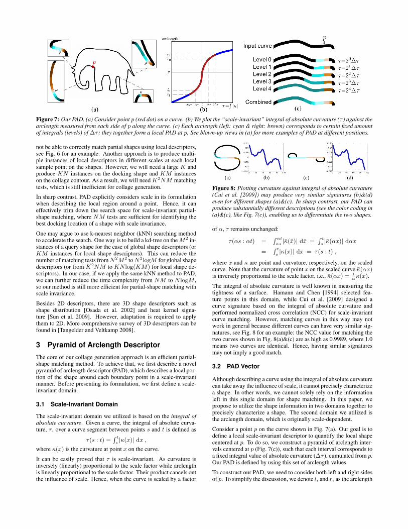
Figure 7: Our PAD. (a) Consider point p (red dot) on a curve. (b) We plot the “scale-invariant” integral of absolute curvature (τ ) against thearclength measured from each side of p along the curve. (c) Each arclength (left: cyan & right: brown) corresponds to certain fixed amountof integrals (levels) of ∆τ ; they together form a local PAD at p. See blown-up views in (a) for more examples of PAD at different positions.
not be able to correctly match partial shapes using local descriptors,see Fig. 6 for an example. Another approach is to produce multi-ple instances of local descriptors in different scales at each localsample point on the shapes. However, we will need a large K andproduce KN instances on the docking shape and KM instanceson the collage contour. As a result, we will need K2NM matchingtests, which is still inefficient for collage generation.
In sharp contrast, PAD explicitly considers scale in its formulationwhen describing the local region around a point. Hence, it caneffectively trim down the search space for scale-invariant partial-shape matching, where NM tests are sufficient for identifying thebest docking location of a shape with scale invariance.
One may argue to use k-nearest neighbor (kNN) searching methodto accelerate the search. One way is to build a kd-tree on the M2 in-stances of a query shape for the case of global shape descriptors (orKM instances for local shape descriptors). This can reduce thenumber of matching tests from N2M2 to N2logM for global shapedescriptors (or from K2NM to KN log(KM) for local shape de-scriptors). In our case, if we apply the same kNN method to PAD,we can further reduce the time complexity from NM to N logM ,so our method is still more efficient for partial-shape matching withscale invariance.
Besides 2D descriptors, there are 3D shape descriptors such asshape distribution [Osada et al. 2002] and heat kernel signa-ture [Sun et al. 2009]. However, adaptation is required to applythem to 2D. More comprehensive survey of 3D descriptors can befound in [Tangelder and Veltkamp 2008].
3 Pyramid of Arclength Descriptor
The core of our collage generation approach is an efficient partial-shape matching method. To achieve that, we first describe a novelpyramid of arclength descriptor (PAD), which describes a local por-tion of the shape around each boundary point in a scale-invariantmanner. Before presenting its formulation, we first define a scale-invariant domain.
3.1 Scale-Invariant Domain
The scale-invariant domain we utilized is based on the integral ofabsolute curvature. Given a curve, the integral of absolute curva-ture, τ , over a curve segment between points s and t is defined as
τ(s : t) =∫ t
s|κ(x)| dx ,
where κ(x) is the curvature at point x on the curve.
It can be easily proved that τ is scale-invariant. As curvature isinversely (linearly) proportional to the scale factor while arclengthis linearly proportional to the scale factor. Their product cancels outthe influence of scale. Hence, when the curve is scaled by a factor
Figure 8: Plotting curvature against integral of absolute curvature(Cui et al. [2009]) may produce very similar signatures (b)&(d)even for different shapes (a)&(c). In sharp contrast, our PAD canproduce substantially different descriptions (see the color coding in(a)&(c), like Fig. 7(c)), enabling us to differentiate the two shapes.
of α, τ remains unchanged:
τ(αs : αt) =∫ αt
αs|κ̄(x̄)| dx̄ =
∫ t
s|κ̄(αx)| dαx
=∫ t
s|κ(x)| dx = τ(s : t) ,
where x̄ and κ̄ are point and curvature, respectively, on the scaledcurve. Note that the curvature of point x on the scaled curve κ̄(αx)is inversely proportional to the scale factor, i.e., κ̄(αx) = 1
ακ(x).
The integral of absolute curvature is well known in measuring thetightness of a surface. Hamann and Chen [1994] selected fea-ture points in this domain, while Cui et al. [2009] designed acurve signature based on the integral of absolute curvature andperformed normalized cross correlation (NCC) for scale-invariantcurve matching. However, matching curves in this way may notwork in general because different curves can have very similar sig-natures, see Fig. 8 for an example: the NCC value for matching thetwo curves shown in Fig. 8(a)&(c) are as high as 0.9989, where 1.0means two curves are identical. Hence, having similar signaturesmay not imply a good match.
3.2 PAD Vector
Although describing a curve using the integral of absolute curvaturecan take away the influence of scale, it cannot precisely characterizea shape. In other words, we cannot solely rely on the informationleft in this single domain for shape matching. In this paper, wepropose to utilize the shape information in two domains together toprecisely characterize a shape. The second domain we utilized isthe arclength domain, which is originally scale-dependent.
Consider a point p on the curve shown in Fig. 7(a). Our goal is todefine a local scale-invariant descriptor to quantify the local shapecentered at p. To do so, we construct a pyramid of arclength inter-vals centered at p (Fig. 7(c)), such that each interval corresponds toa fixed integral value of absolute curvature (∆τ ), cumulated from p.Our PAD is defined by using this set of arclength values.
To construct our PAD, we need to consider both left and right sidesof p. To simplify the discussion, we denote li and ri as the arclength
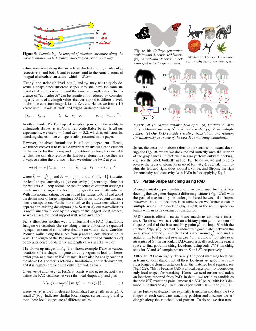
Figure 9: Cumulating the integral of absolute curvature along thecurve is analogous to Pacman collecting cherries on its way.
values measured along the curve from the left and right sides of p,respectively, and both li and ri correspond to the same amount ofintegral of absolute curvature, which is 2i∆τ .
Clearly, one arclength level, say l0 and r0, may not uniquely de-scribe a shape since different shapes may still have the same in-tegral of absolute curvature and the same arclength value. Such achance of “coincidence” can be significantly reduced by consider-ing a pyramid of arclength values that correspond to different levelsof absolute curvature integral, i.e., 2i∆τ , etc. Hence, we form a 1Dvector with n levels of “left” and “right” arclength values:
[ ln−1 ln−2 · · · l1 l0 r0 r1 · · · rn−2 rn−1 ]T .
In other words, PAD’s shape description power, or the ability todistinguish shapes, is scalable, i.e., controllable by n. In all ourexperiments, we use n = 5 and ∆τ = 0.2, which is sufficient formatching shapes in the collage results presented in the paper.
However, the above formulation is still scale-dependent. Hence,we further convert it to be scale-invariant by dividing each elementin the vector by the corresponding last-level arclength value. Af-ter that, we can also remove the last-level elements since they arealways one after the division. Thus, we define the PAD at p as
m(p) = s [ l̂n−2 · · · l̂1 l̂0 r̂0 r̂1 · · · r̂n−2 ]T .
where l̂i = li2iln−1
and r̂i = ri2irn−1
and s ∈ {1,−1} indicates
the local shape convexity (+1) or concavity (-1) around p. Note thatthe weights 2−i help normalize the influence of different arclengthlevels since the larger the level, the longer the arclength value is.With this normalization, we can bound the values to [0, 1] and avoidthe dominance of large magnitude PADs in our subsequent distancemetric computation. Furthermore, unlike the global normalizationapproach in existing descriptors (see Section 2), our normalizationis local, since we divide by the length of the longest local interval,so we can achieve local support with scale invariance.
Fig. 9 illustrates another way to understand the PAD formulation.Imagine we distribute cherries along a curve at locations separatedby equal amount of cumulative absolute curvature (∆τ ). ConsiderPacman walks along the curve from p and collects cherries on itsway. The length of the Pacman path to collect fixed numbers (2i)of cherries corresponds to the arclength values in PAD vector.
The blown-up images in Fig. 7(a) shows example PADs at variouslocations of the shape. In general, curly segments lead to shorterarclengths, and smaller PAD values. It can also be easily seen thatthe above PAD vector is rotation-, translation-, and scale-invariant,and it is highly compact with only eight values for n=5.
Given m(p) and m(q) as PADs at points p and q, respectively, wedefine the PAD distance between the local shapes at p and q as:
D(p, q) = maxi
{ | mi(p) − mi(q) | } , (1)
where mi(p) is the i-th element (normalized arclength) in m(p). Asmall D(p, q) indicates similar local shapes surrounding p and q,even these local shapes are of different scales.
Figure 10: Collage generationwith inward docking (red butter-fly) or outward docking (blackbutterfly) onto the gray canvas.
Figure 11: This work uses ar-bitrary shapes of varying sizes.
Figure 12: (a) Signed distance field of S. (b) Docking S′ ontoS. (c) Manual docking S′ in a single scale. (d) S′ in multiplescales. (e) Our PAD considers scaling, translation, and rotationsimultaneously, see some of the best K% matching candidates.
So far, the description above refers to the scenario of inward dock-ing, see Fig. 10, where we dock the red butterfly onto the interiorof the gray canvas. In fact, we can also perform outward docking,e.g., see the black butterfly in Fig. 10. To do so, we just need toreverse the order of elements in m(p) (or m(q)), equivalently flip-ping the left and right sides around p (or q), and flipping the signfor convexity and concavity (s in PAD) before applying Eq. 1.
3.3 Partial-Shape Matching using PAD
Manual partial-shape matching can be performed by iterativelydocking the two given shapes at different positions (Fig. 12(c)) withthe goal of maximizing the arclength shared between the shapes.However, this soon becomes intractable when we further considermultiple scales in the docking (Fig. 12(d)), as the search space ex-pands with an extra continuous dimension.
PAD supports efficient partial-shape matching with scale invari-ance. To do so, we start with an arbitrary point pi on contour ofshape S and find the best matching point p′j on shape S′ with thesmallest D(pi, p
′
j). A small D indicates a good match between thelocal shape around pi and the local shape around p′j , and such amatch is the best not just over all positions around S′, but also overall scales of S′. In particular, PAD can drastically reduce the searchspace to find good matching locations, using only NM matchingtests for N and M sample points on S and S′, respectively.
Although PAD can highly efficiently find good matching locationsin terms of local shapes, not all these locations are good if we con-sider longer arclength distances from the matched local regions, seeFig. 12(e). This is because PAD is a local descriptor, so it considersonly local shapes for matching. Hence, we need further evaluationon locations reported from PAD. In detail, we retain as candidatesthe best K% matching pairs (among the NM pairs) with PAD dis-tance D < threshold β. In all our experiments, K=1 and β=0.4.
In the further evaluation, we explicitly transform and dock the twoshapes at each candidate matching position and measure the ar-clength along the matched local portion. To do so, we first trans-
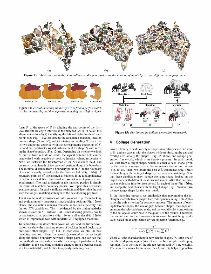
(a) (b) (c)
Figure 13: “Australian Animals.” Our collage results generated using the same set of input clip arts but different scale preferences.
Figure 14: Partial-matching similarity varies from a perfect matchto a less matchable, and then a poorly-matching case (left to right).
form S′ to the space of S by aligning the end-points of the first-level (finest) arclength intervals in the matched PADs. In detail, thisalignment is done by i) identifying the left and right first-level end-points (see Fig. 7(a)&(c)) around the associated matched locationon each shape (S and S′), and ii) rotating and scaling S′, such thatits two endpoints coincide with the corresponding endpoints of S.Second, we construct a signed distance field for shape S with zeroson the shape boundary (Fig. 12(a)). Depending on whether we dockS′ onto S from outside or inside, the signed distance field can besynthesized with negative or positive interior values, respectively.Next, we rasterize the transformed S′ on S’s distance field, andmeasure the arclength of the matched portion along S′’s boundary.The minimal distance from a boundary point on S′ to the boundaryof S can be easily looked up by the distance field (Fig. 12(b)). Aboundary point on S′ is classified as matched if the lookup distanceis below a user defined threshold δ. We set δ as 4 pixels in ourexperiments. The total arclength of the matched portion is simplythe count of matched boundary points. We repeat this dock-and-evaluate process for each candidate position, and determine the onewith the longest matched arclength as the best docking position.
Thanks to the scale invariance of PAD, we need to perform dockingand evaluation only once per distinct docking position (Fig. 12(e)).Hence, the evaluation remains tractable as we can efficiently findthe top K% candidates. This is evidenced by the timing statisticsshown in Section 5. Without PAD, such docking process has tobe performed at all positions (Fig. 12(c)) in all scales (Fig. 12(d)),which is impractical even with modern GPU-equipped machines.
To demonstrate the description power of PAD and the further eval-uation, we show the matching scores of docking the red duck shapeonto four other shapes (Fig. 14). In each case, we plot the bestmatching position. From the scores (measured as the arclengthalong the shared boundary between a shape pair), one can see thatour method can reasonably describe the change of partial-matchingsimilarity as the matching situation changes from a perfect matchto a less matchable, and further to a poorly-matching case.
Figure 15: Our bottom-up collage generation framework.
4 Collage Generation
Given a library of wide variety of shapes in arbitrary scale, we wantto fill a given canvas with the shapes while minimizing the gap andoverlap area among the shapes. Fig. 15 shows our collage gen-eration framework, which is an iterative process. In each round,we start from a target shape, which is either a seed shape givenby the user or a merged shape that represents the current collage(Fig. 15(c)). Then, we obtain the best K% candidates (Fig. 15(a))for matching with the target shape by partial-shape matching. Notethat these candidates may include the same shape docked on thetarget shape with different locations and scales. After that, we eval-uate an objective function (see below) for each of them (Fig. 15(b)),and merge the best choice with the target shape (Fig. 15(c)) to formthe new target shape for the next round.
In the matching process, we emphasize that maximizing the ar-clength shared between shapes (see red segments in Fig. 15(a)&(b))is not the only criterion for aesthetic purpose. The amount of over-lap between shapes, the size of gaps between shapes, the shape ori-entation, the selected shape scale, and the overall color compositionof the collage all contribute to the quality of the results. Therefore,the second step in the framework is to score the matching candi-dates based on an application-driven objective function, e.g.,
Z =ω1L
√
ω2
∑
O2
i + ω3
∑
G2
i
,
where L is the shared arclength between the shapes, Oi is the size ofthe ith overlapping region (since there can be multiple overlappingregions), Gi is the size of the ith gap region, and ωi’s are weights.The sum of squares formulation for Oi and Gi helps to penalize
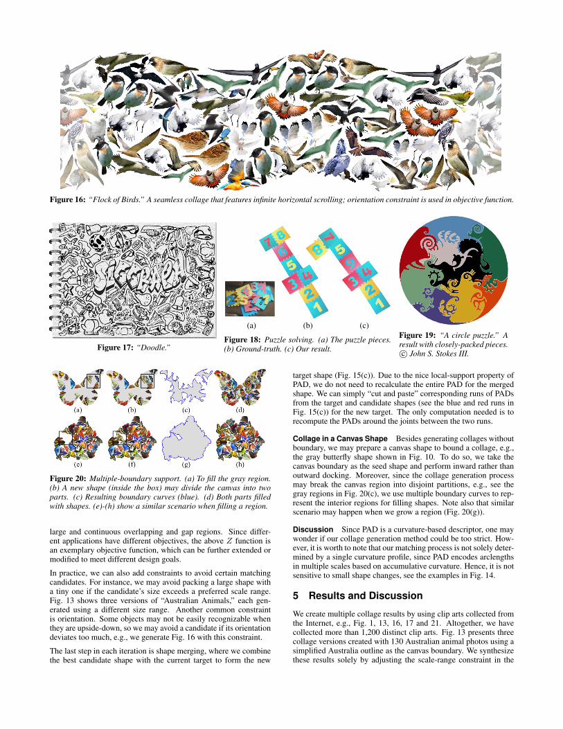
Figure 16: “Flock of Birds.” A seamless collage that features infinite horizontal scrolling; orientation constraint is used in objective function.
Figure 17: “Doodle.”
(a) (b) (c)
Figure 18: Puzzle solving. (a) The puzzle pieces.(b) Ground-truth. (c) Our result.
Figure 19: “A circle puzzle.” Aresult with closely-packed pieces.c© John S. Stokes III.
Figure 20: Multiple-boundary support. (a) To fill the gray region.(b) A new shape (inside the box) may divide the canvas into twoparts. (c) Resulting boundary curves (blue). (d) Both parts filledwith shapes. (e)-(h) show a similar scenario when filling a region.
large and continuous overlapping and gap regions. Since differ-ent applications have different objectives, the above Z function isan exemplary objective function, which can be further extended ormodified to meet different design goals.
In practice, we can also add constraints to avoid certain matchingcandidates. For instance, we may avoid packing a large shape witha tiny one if the candidate’s size exceeds a preferred scale range.Fig. 13 shows three versions of “Australian Animals,” each gen-erated using a different size range. Another common constraintis orientation. Some objects may not be easily recognizable whenthey are upside-down, so we may avoid a candidate if its orientationdeviates too much, e.g., we generate Fig. 16 with this constraint.
The last step in each iteration is shape merging, where we combinethe best candidate shape with the current target to form the new
target shape (Fig. 15(c)). Due to the nice local-support property ofPAD, we do not need to recalculate the entire PAD for the mergedshape. We can simply “cut and paste” corresponding runs of PADsfrom the target and candidate shapes (see the blue and red runs inFig. 15(c)) for the new target. The only computation needed is torecompute the PADs around the joints between the two runs.
Collage in a Canvas Shape Besides generating collages withoutboundary, we may prepare a canvas shape to bound a collage, e.g.,the gray butterfly shape shown in Fig. 10. To do so, we take thecanvas boundary as the seed shape and perform inward rather thanoutward docking. Moreover, since the collage generation processmay break the canvas region into disjoint partitions, e.g., see thegray regions in Fig. 20(c), we use multiple boundary curves to rep-resent the interior regions for filling shapes. Note also that similarscenario may happen when we grow a region (Fig. 20(g)).
Discussion Since PAD is a curvature-based descriptor, one maywonder if our collage generation method could be too strict. How-ever, it is worth to note that our matching process is not solely deter-mined by a single curvature profile, since PAD encodes arclengthsin multiple scales based on accumulative curvature. Hence, it is notsensitive to small shape changes, see the examples in Fig. 14.
5 Results and Discussion
We create multiple collage results by using clip arts collected fromthe Internet, e.g., Fig. 1, 13, 16, 17 and 21. Altogether, we havecollected more than 1,200 distinct clip arts. Fig. 13 presents threecollage versions created with 130 Australian animal photos using asimplified Australia outline as the canvas boundary. We synthesizethese results solely by adjusting the scale-range constraint in the
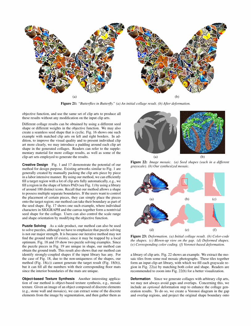
(a) (b)
Figure 21: “Butterflies in Butterfly.” (a) An initial collage result. (b) After deformation.
objective function, and use the same set of clip arts to produce allthese results without any modification on the input clip arts.
Different collage results can be obtained by using a different seedshape or different weights in the objective function. We may alsocreate a seamless seed shape that is cyclic. Fig. 16 shows one suchexample with matched clip arts on left and right borders. In ad-dition, to improve the visual quality and to present individual clipart more clearly, we may introduce a padding around each clip artshape in the generated collages. Readers can refer to the supple-mentary material for more collage results, as well as some of theclip-art sets employed to generate the results.
Creative Design Fig. 1 and 17 demonstrate the potential of ourmethod for design purpose. Existing artworks similar to Fig. 1 aregenerally created by manually packing the clip arts piece by piecein a labor intensive manner. By using our method, we can efficientlyfill a target region with a lot of clip arts fully automatically, e.g., wefill a region in the shape of letters PAD (see Fig. 1) by using a libraryof around 100 distinct icons. Recall that our method allows a shapeto possess multiple separate boundaries. If the users want to controlthe placement of certain pieces, they can simply place the piecesonto the target region; our method can take their boundary as part ofthe seed shape. Fig. 17 shows one such example, where individualcharacters in SIGGRAPH and the canvas together form a nontrivialseed shape for the collage. Users can also control the scale rangeand shape orientation by modifying the objective function.
Puzzle Solving As a side product, our method can also be usedto solve puzzles, although we have to emphasize that puzzle solvingis not our major strength. It is because our iterative method may notfind the ground truth (if exists), since it may be trapped by a localoptimum. Fig. 18 and 19 show two puzzle solving examples. Sincethe puzzle pieces in Fig. 19 are unique in shape, our method canobtain the ground truth. This result also shows that our method canidentify strongly-coupled shapes if the input library has any. Forthe case of Fig. 18, due to the non-uniqueness of the shapes, ourmethod (Fig. 18(c)) cannot generate the target result (Fig. 18(b)),but it can fill all the numbers with their corresponding floor matssince the interior boundaries of the mats are unique.
Object-based Texture Synthesis Another interesting applica-tion of our method is object-based texture synthesis, e.g., mosaictexture. Given an image of an object composed of discrete elements(e.g., stone wall and mosaics), we can extract some of the discreteelements from the image by segmentation, and then gather them as
(a) (b)
Figure 22: Image mosaic. (a) Seed shapes (each in a differentgrayscale). (b) Our synthesized mosaic.
(a) (b) (c)
(d) (e) (f)
Figure 23: Deformation. (a) Initial collage result. (b) Color-codethe shapes. (c) Blown-up view on the gap. (d) Deformed shapes.(e) Corresponding color coding. (f) Voronoi-based deformation.
a library of clip arts. Fig. 22 shows an example. We extract the mo-saic tiles from some real mosaic photographs. These tiles togetherform an input clip-art library, with which we fill each grayscale re-gion in Fig. 22(a) by matching both color and shape. Readers arerecommended to zoom into Fig. 22(b) for a better visualization.
Deformation Since we generate collages with arbitrary clip arts,we may not always avoid gaps and overlaps. Concerning this, weinclude an optional deformation step to enhance the collage gen-eration results. To do so, we create a Voronoi diagram in the gapand overlap regions, and project the original shape boundary onto
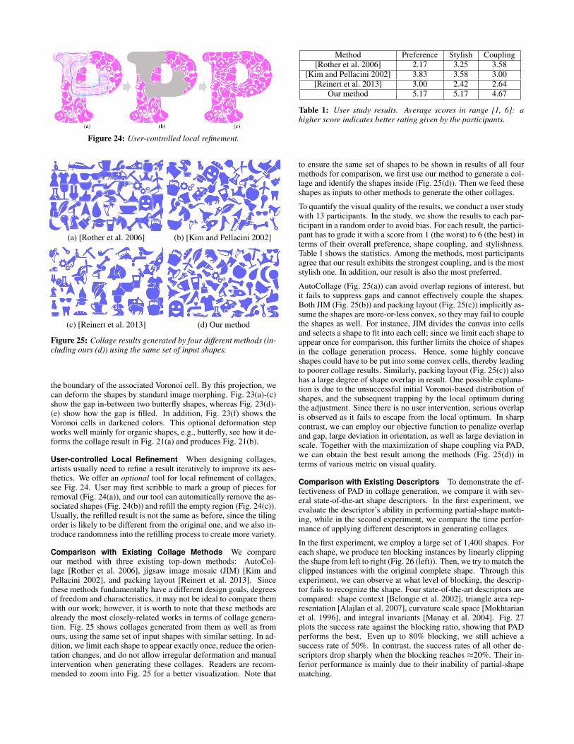
Figure 24: User-controlled local refinement.
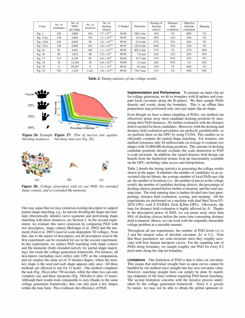
(a) [Rother et al. 2006] (b) [Kim and Pellacini 2002]
(c) [Reinert et al. 2013] (d) Our method
Figure 25: Collage results generated by four different methods (in-cluding ours (d)) using the same set of input shapes.
the boundary of the associated Voronoi cell. By this projection, wecan deform the shapes by standard image morphing. Fig. 23(a)-(c)show the gap in-between two butterfly shapes, whereas Fig. 23(d)-(e) show how the gap is filled. In addition, Fig. 23(f) shows theVoronoi cells in darkened colors. This optional deformation stepworks well mainly for organic shapes, e.g., butterfly, see how it de-forms the collage result in Fig. 21(a) and produces Fig. 21(b).
User-controlled Local Refinement When designing collages,artists usually need to refine a result iteratively to improve its aes-thetics. We offer an optional tool for local refinement of collages,see Fig. 24. User may first scribble to mark a group of pieces forremoval (Fig. 24(a)), and our tool can automatically remove the as-sociated shapes (Fig. 24(b)) and refill the empty region (Fig. 24(c)).Usually, the refilled result is not the same as before, since the tilingorder is likely to be different from the original one, and we also in-troduce randomness into the refilling process to create more variety.
Comparison with Existing Collage Methods We compareour method with three existing top-down methods: AutoCol-lage [Rother et al. 2006], jigsaw image mosaic (JIM) [Kim andPellacini 2002], and packing layout [Reinert et al. 2013]. Sincethese methods fundamentally have a different design goals, degreesof freedom and characteristics, it may not be ideal to compare themwith our work; however, it is worth to note that these methods arealready the most closely-related works in terms of collage genera-tion. Fig. 25 shows collages generated from them as well as fromours, using the same set of input shapes with similar setting. In ad-dition, we limit each shape to appear exactly once, reduce the orien-tation changes, and do not allow irregular deformation and manualintervention when generating these collages. Readers are recom-mended to zoom into Fig. 25 for a better visualization. Note that
Method Preference Stylish Coupling
[Rother et al. 2006] 2.17 3.25 3.58
[Kim and Pellacini 2002] 3.83 3.58 3.00
[Reinert et al. 2013] 3.00 2.42 2.64
Our method 5.17 5.17 4.67
Table 1: User study results. Average scores in range [1, 6]: ahigher score indicates better rating given by the participants.
to ensure the same set of shapes to be shown in results of all fourmethods for comparison, we first use our method to generate a col-lage and identify the shapes inside (Fig. 25(d)). Then we feed theseshapes as inputs to other methods to generate the other collages.
To quantify the visual quality of the results, we conduct a user studywith 13 participants. In the study, we show the results to each par-ticipant in a random order to avoid bias. For each result, the partici-pant has to grade it with a score from 1 (the worst) to 6 (the best) interms of their overall preference, shape coupling, and stylishness.Table 1 shows the statistics. Among the methods, most participantsagree that our result exhibits the strongest coupling, and is the moststylish one. In addition, our result is also the most preferred.
AutoCollage (Fig. 25(a)) can avoid overlap regions of interest, butit fails to suppress gaps and cannot effectively couple the shapes.Both JIM (Fig. 25(b)) and packing layout (Fig. 25(c)) implicitly as-sume the shapes are more-or-less convex, so they may fail to couplethe shapes as well. For instance, JIM divides the canvas into cellsand selects a shape to fit into each cell; since we limit each shape toappear once for comparison, this further limits the choice of shapesin the collage generation process. Hence, some highly concaveshapes could have to be put into some convex cells, thereby leadingto poorer collage results. Similarly, packing layout (Fig. 25(c)) alsohas a large degree of shape overlap in result. One possible explana-tion is due to the unsuccessful initial Voronoi-based distribution ofshapes, and the subsequent trapping by the local optimum duringthe adjustment. Since there is no user intervention, serious overlapis observed as it fails to escape from the local optimum. In sharpcontrast, we can employ our objective function to penalize overlapand gap, large deviation in orientation, as well as large deviation inscale. Together with the maximization of shape coupling via PAD,we can obtain the best result among the methods (Fig. 25(d)) interms of various metric on visual quality.
Comparison with Existing Descriptors To demonstrate the ef-fectiveness of PAD in collage generation, we compare it with sev-eral state-of-the-art shape descriptors. In the first experiment, weevaluate the descriptor’s ability in performing partial-shape match-ing, while in the second experiment, we compare the time perfor-mance of applying different descriptors in generating collages.
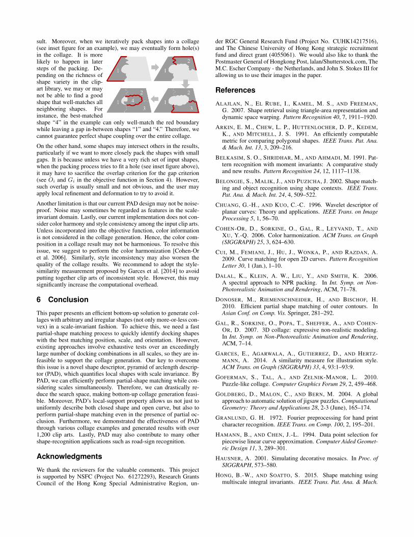
In the first experiment, we employ a large set of 1,400 shapes. Foreach shape, we produce ten blocking instances by linearly clippingthe shape from left to right (Fig. 26 (left)). Then, we try to match theclipped instances with the original complete shape. Through thisexperiment, we can observe at what level of blocking, the descrip-tor fails to recognize the shape. Four state-of-the-art descriptors arecompared: shape context [Belongie et al. 2002], triangle area rep-resentation [Alajlan et al. 2007], curvature scale space [Mokhtarianet al. 1996], and integral invariants [Manay et al. 2004]. Fig. 27plots the success rate against the blocking ratio, showing that PADperforms the best. Even up to 80% blocking, we still achieve asuccess rate of 50%. In contrast, the success rates of all other de-scriptors drop sharply when the blocking reaches ≈20%. Their in-ferior performance is mainly due to their inability of partial-shapematching.
CasesNo. of
candidates
No. of
PADs
per shape
No. of
iterations
No. of
docking
choices
% Pruned Total time
Pruning of
docking
choices
Distance
field
evaluation
Objective
function
evaluation
Merging
Fig. 1 120 4,960 194 7.5 ×910 99.96 186.3 min 16% 3% 80% 1%
Fig. 13(a) 128 6,804 334 2.1 ×10¹⁰ 99.95 22.8 min 49% 12% 36% 3%
Fig. 13(b) 128 6,804 69 2.6 ×10¹⁰ 99.94 51.9 min 57% 15% 26% 3%
Fig. 13(c) 128 6,804 143 2.0 ×10¹⁰ 99.93 122.9 min 64% 12% 22% 2%
Fig. 21 83 4,201 102 1.1 ×10¹⁰ 99.83 405.3 min 17% 7% 27% 49%
Fig. 16 86 3,631 90 3.0 ×10⁹ 99.90 7.0 min 42% 11% 28% 19%
Fig. 17 112 4,136 92 6.0 ×10⁹ 99.04 25.7 min 15% 51% 25% 9%
Fig. 18 18 12,340 18 4.0 ×10¹⁵ 99.09 3.2 min 10% 47% 1% 42%
Fig. 19 9 50,247 9 1.1 ×10⁹ 99.95 0.2 min 23% 7% 69% 1%
Fig. 22 734 1,225 1,421 3.8 ×10¹⁰ 99.99 718.3 min 11% 1% 59% 29%
Table 2: Timing statistics of our collage results.
Figure 26: Exampleblocking instances.
Figure 27: Plot of success rate againstblocking ratio (see Fig. 26).
(a) (b) (c)
Figure 28: Collage generation with (a) our PAD, (b) extendedshape context, and (c) extended Hu moments.
One may argue that we may extend an existing descriptor to supportpartial-shape matching, e.g., by naı̈vely dividing the shape into mul-tiple (theoretically infinite) curve segments and performing shapematching with these instances, see Section 2. In the second exper-iment, we evaluate this naı̈ve extension by comparing PAD withtwo descriptors, shape context [Belongie et al. 2002] and Hu mo-ments [Gal et al. 2007] (used in scale-dependent 3D collage). Notethat, due to the nature of descriptors, not all descriptors used in thefirst experiment can be extended for use in the second experiment.In this experiment, we replace PAD matching with shape contextand Hu moments (both extended naı̈vely for partial-shape match-ing), but retain the collage generation framework. For fairness, alldescriptors (including ours) utilize only CPU in the computation,and we employ the same set of 35 distinct shapes, where the mon-key shape is the seed and each shape appears only once. All threemethods are allowed to run for 12 hours. Our method completesthe task (Fig. 28(a)) after 750 seconds, while the other two can onlycomplete one and three iterations (Fig. 28(b)&(c)) after 12 hours.Although their results look comparable to ours (thanks to the samecollage generation framework), they can only pack a few shapeswithin the time limit. This evidences the efficiency of PAD.
Implementation and Performance To prepare an input clip artfor collage generation, we fit its boundary with B-splines and com-pute local curvature along the B-splines. We then sample PADsdensely and evenly along the boundary. This is an offline datapreparation step performed only once per input clip-art shape.
Even though we have a dense sampling of PADs, our method caneffectively prune away most candidate docking positions by mea-suring their PAD distances. No further evaluation with the distancefield is needed for these candidates. Moreover, both the docking anddistance field evaluation procedures are perfectly parallelizable, sowe perform them on the GPU by using CUDA. This enables us toefficiently compute the partial-shape matching. For instance, ourmethod consumes only 64 milliseconds on average to evaluate twoshapes with 25,000,000 docking positions. This amount of dockingcandidate positions already excludes the scale dimension as PADis scale-invariant. In addition, the signed distance field design canbenefit from the hardwired texture look-up functionality availableon the GPU, including value access and interpolation.
Table 2 details the timing statistics in generating the collage resultsshown in the paper. It tabulates the number of candidates in an as-sociated clip-art library, the average number of local PADs per clipart, the number of iterations (i.e., the number of pieces in the collageresult), the number of candidate docking choices, the percentage ofdocking choices pruned before further evaluation, and the total run-ning time. The total running time is further divided into four parts:pruning, distance field evaluation, scoring, and merging. All theexperiments are performed on a machine with dual Intel Xeon E5-2670 CPUs with 8 NVIDIA Tesla K20m GPUs. Obviously, thetime for distance field evaluation is highly affected by K. Thanksto the description power of PAD, we can prune away more than99% of docking choices before the more time-consuming distancefield evaluation. Hence, we can work with the originally intractablecollage problem in a tractable manner.
Throughout all our experiments, the number of PAD levels (n) is5 and the integral value of absolute curvature ∆τ is 0.2. Notethat these parameters are scale-invariant since they roughly asso-ciate with how human interprets curves. For the sampling rate ofPADs along boundary, we sample roughly one PAD for every 0.2pixel units along the clip-art boundary.
Limitations One limitation of PAD is that it relies on curvature.This means that individual straight lines in open curves cannot behandled by our method since straight line has zero curvature value.However, matching straight lines can simply be done by match-ing endpoints of the lines without requiring PAD-based matching.The second limitation concerns with the iterative process under-taken by the collage generation framework. Since it is greedyby nature, we may not be able to obtain the global optimum re-
sult. Moreover, when we iteratively pack shapes into a collage(see inset figure for an example), we may eventually form hole(s)in the collage. It is morelikely to happen in latersteps of the packing. De-pending on the richness ofshape variety in the clip-art library, we may or maynot be able to find a goodshape that well-matches allneighboring shapes. Forinstance, the best-matchedshape “4” in the example can only well-match the red boundarywhile leaving a gap in-between shapes “1” and “4.” Therefore, wecannot guarantee perfect shape coupling over the entire collage.
On the other hand, some shapes may intersect others in the results,particularly if we want to more closely pack the shapes with smallgaps. It is because unless we have a very rich set of input shapes,when the packing process tries to fit a hole (see inset figure above),it may have to sacrifice the overlap criterion for the gap criterion(see Oi and Gi in the objective function in Section 4). However,such overlap is usually small and not obvious, and the user mayapply local refinement and deformation to try to avoid it.
Another limitation is that our current PAD design may not be noise-proof. Noise may sometimes be regarded as features in the scale-invariant domain. Lastly, our current implementation does not con-sider color harmony and style consistency among the input clip arts.Unless incorporated into the objective function, color informationis not considered in the collage generation. Hence, the color com-position in a collage result may not be harmonious. To resolve thisissue, we suggest to perform the color harmonization [Cohen-Oret al. 2006]. Similarly, style inconsistency may also worsen thequality of the collage results. We recommend to adopt the style-similarity measurement proposed by Garces et al. [2014] to avoidputting together clip arts of inconsistent style. However, this maysignificantly increase the computational overhead.
6 Conclusion
This paper presents an efficient bottom-up solution to generate col-lages with arbitrary and irregular shapes (not only more-or-less con-vex) in a scale-invariant fashion. To achieve this, we need a fastpartial-shape matching process to quickly identify docking shapeswith the best matching position, scale, and orientation. However,existing approaches involve exhaustive tests over an exceedinglylarge number of docking combinations in all scales, so they are in-feasible to support the collage generation. Our key to overcomethis issue is a novel shape descriptor, pyramid of arclength descrip-tor (PAD), which quantifies local shapes with scale invariance. ByPAD, we can efficiently perform partial-shape matching while con-sidering scales simultaneously. Therefore, we can drastically re-duce the search space, making bottom-up collage generation feasi-ble. Moreover, PAD’s local-support property allows us not just touniformly describe both closed shape and open curve, but also toperform partial-shape matching even in the presence of partial oc-clusion. Furthermore, we demonstrated the effectiveness of PADthrough various collage examples and generated results with over1,200 clip arts. Lastly, PAD may also contribute to many othershape-recognition applications such as road-sign recognition.
Acknowledgments
We thank the reviewers for the valuable comments. This projectis supported by NSFC (Project No. 61272293), Research GrantsCouncil of the Hong Kong Special Administrative Region, un-
der RGC General Research Fund (Project No. CUHK14217516),and The Chinese University of Hong Kong strategic recruitmentfund and direct grant (4055061). We would also like to thank thePostmaster General of Hongkong Post, lalan/Shutterstock.com, TheM.C. Escher Company - the Netherlands, and John S. Stokes III forallowing us to use their images in the paper.
References
ALAJLAN, N., EL RUBE, I., KAMEL, M. S., AND FREEMAN,G. 2007. Shape retrieval using triangle-area representation anddynamic space warping. Pattern Recognition 40, 7, 1911–1920.
ARKIN, E. M., CHEW, L. P., HUTTENLOCHER, D. P., KEDEM,K., AND MITCHELL, J. S. 1991. An efficiently computablemetric for comparing polygonal shapes. IEEE Trans. Pat. Ana.& Mach. Int. 13, 3, 209–216.
BELKASIM, S. O., SHRIDHAR, M., AND AHMADI, M. 1991. Pat-tern recognition with moment invariants: A comparative studyand new results. Pattern Recognition 24, 12, 1117–1138.
BELONGIE, S., MALIK, J., AND PUZICHA, J. 2002. Shape match-ing and object recognition using shape contexts. IEEE Trans.Pat. Ana. & Mach. Int. 24, 4, 509–522.
CHUANG, G.-H., AND KUO, C.-C. 1996. Wavelet descriptor ofplanar curves: Theory and applications. IEEE Trans. on ImageProcessing 5, 1, 56–70.
COHEN-OR, D., SORKINE, O., GAL, R., LEYVAND, T., AND
XU, Y.-Q. 2006. Color harmonization. ACM Trans. on Graph(SIGGRAPH) 25, 3, 624–630.
CUI, M., FEMIANI, J., HU, J., WONKA, P., AND RAZDAN, A.2009. Curve matching for open 2D curves. Pattern RecognitionLetter 30, 1 (Jan.), 1–10.
DALAL, K., KLEIN, A. W., LIU, Y., AND SMITH, K. 2006.A spectral approach to NPR packing. In Int. Symp. on Non-Photorealistic Animation and Rendering, ACM, 71–78.
DONOSER, M., RIEMENSCHNEIDER, H., AND BISCHOF, H.2010. Efficient partial shape matching of outer contours. InAsian Conf. on Comp. Vis. Springer, 281–292.
GAL, R., SORKINE, O., POPA, T., SHEFFER, A., AND COHEN-OR, D. 2007. 3D collage: expressive non-realistic modeling.In Int. Symp. on Non-Photorealistic Animation and Rendering,ACM, 7–14.
GARCES, E., AGARWALA, A., GUTIERREZ, D., AND HERTZ-MANN, A. 2014. A similarity measure for illustration style.ACM Trans. on Graph (SIGGRAPH) 33, 4, 93:1–93:9.
GOFERMAN, S., TAL, A., AND ZELNIK-MANOR, L. 2010.Puzzle-like collage. Computer Graphics Forum 29, 2, 459–468.
GOLDBERG, D., MALON, C., AND BERN, M. 2004. A globalapproach to automatic solution of jigsaw puzzles. ComputationalGeometry: Theory and Applications 28, 2-3 (June), 165–174.
GRANLUND, G. H. 1972. Fourier preprocessing for hand printcharacter recognition. IEEE Trans. on Comp. 100, 2, 195–201.
HAMANN, B., AND CHEN, J.-L. 1994. Data point selection forpiecewise linear curve approximation. Computer Aided Geomet-ric Design 11, 3, 289–301.
HAUSNER, A. 2001. Simulating decorative mosaics. In Proc. ofSIGGRAPH, 573–580.
HONG, B.-W., AND SOATTO, S. 2015. Shape matching usingmultiscale integral invariants. IEEE Trans. Pat. Ana. & Mach.
Int., 1, 151–160.
HU, W., CHEN, Z., PAN, H., YU, Y., GRINSPUN, E., AND
WANG, W. 2016. Surface mosaic synthesis with irregular tiles.IEEE Trans. Vis. & Comp. Graphics 22, 3 (Mar.), 1302–1313.
HU, M.-K. 1962. Visual pattern recognition by moment invariants.IRE Trans. on Info. Theory 8, 2, 179–187.
HUANG, H., ZHANG, L., AND ZHANG, H.-C. 2011. Arcimboldo-like collage using internet images. ACM Trans. on Graph (SIG-GRAPH Asia) 30, 6 (Dec.), 155:1–155:8.
HUANG, Z., WANG, J., FU, H., AND LAU, R. W. 2014. Structuredmechanical collage. IEEE Trans. Vis. & Comp. Graphics 20, 7,1076–1082.
KAPLAN, C. S., AND SALESIN, D. H. 2000. Escherization. InProc. of SIGGRAPH, 499–510.
KAPLAN, C. S., AND SALESIN, D. H. 2004. Dihedral escheriza-tion. In Proc. of Graphics Interface, Canadian Human-ComputerCommunications Society, 255–262.
KHOTANZAD, A., AND HONG, Y. H. 1990. Invariant image recog-nition by Zernike moments. IEEE Trans. Pat. Ana. & Mach. Int.12, 5, 489–497.
KIM, J., AND PELLACINI, F. 2002. Jigsaw image mosaics. InSIGGRAPH 2002, 657–664.
KRISH, K., AND SNYDER, W. 2008. A new accumulator-basedapproach to shape recognition. In Advances in Visual Comput-ing, vol. 5359. 157–169.
LEE, S.-M., ABBOTT, A. L., CLARK, N. A., AND ARAMAN,P. A. 2006. A shape representation for planar curves by shapesignature harmonic embedding. In Proc. IEEE Conf. on Comp.Vis. and Pat. Rec., vol. 2, 1940–1947.
MANAY, S., HONG, B., YEZZI, A., AND SOATTO, S. 2004. In-tegral invariant signatures. In Proc. Euro. Conf. on Comp. Vis.,Springer, 87–99.
MOKHTARIAN, F., AND MACKWORTH, A. K. 1992. A theoryof multiscale, curvature-based shape representation for planarcurves. IEEE Trans. Pat. Ana. & Mach. Int. 14, 8, 789–805.
MOKHTARIAN, F., ABBASI, S., AND KITTLER, J. 1996. Ef-ficient and robust retrieval by shape content through curvaturescale space. In Int. Workshop on Image Databases and Multime-dia Search, 35–42.
ORCHARD, J., AND KAPLAN, C. S. 2008. Cut-out image mosaics.In Int. Symp. on Non-Photorealistic Animation and Rendering,79–87.
OSADA, R., FUNKHOUSER, T., CHAZELLE, B., AND DOBKIN,D. 2002. Shape distributions. ACM Trans. on Graph 21, 4,807–832.
PERSOON, E., AND FU, K.-S. 1977. Shape discrimination usingFourier descriptors. IEEE Trans. on Systems, Man and Cyber-netics 7, 3, 170–179.
REINERT, B., RITSCHEL, T., AND SEIDEL, H.-P. 2013. Interac-tive by-example design of artistic packing layouts. ACM Trans.on Graph (SIGGRAPH Asia) 32, 6 (Nov.), 218:1–218:7.
ROTHER, C., BORDEAUX, L., HAMADI, Y., AND BLAKE, A.2006. Autocollage. In ACM Trans. on Graph (SIGGRAPH),847–852.
SHENG, Y., AND SHEN, L. 1994. Orthogonal Fourier-Mellin mo-ments for invariant pattern recognition. The Journal of the Opti-cal Society of America-A 11, 6, 1748–1757.
SUN, J., OVSJANIKOV, M., AND GUIBAS, L. 2009. A concise andprovably informative multi-scale signature based on heat diffu-sion. In Computer Graphics Forum, vol. 28, Wiley Online Li-brary, 1383–1392.
TABBONE, S., WENDLING, L., AND SALMON, J.-P. 2006. A newshape descriptor defined on the Radon transform. Comp. Vis. &Image Understanding 102, 1, 42–51.
TANGELDER, J. W., AND VELTKAMP, R. C. 2008. A survey ofcontent based 3D shape retrieval methods. Multimedia tools andapplications 39, 3, 441–471.
VAN KAICK, O., ZHANG, H., HAMARNEH, G., AND COHEN-OR, D. 2011. A survey on shape correspondence. In ComputerGraphics Forum, vol. 30, Wiley Online Library, 1681–1707.
VELTKAMP, R. C., AND HAGEDOORN, M. 2001. State of the artin shape matching. In Principles of visual information retrieval.Springer, 87–119.
XU, J., AND KAPLAN, C. S. 2007. Calligraphic packing. In Proc.of Graphics Interface, ACM, 43–50.
YANG, M., KPALMA, K., AND RONSIN, J. 2008. A survey ofshape feature extraction techniques. Pattern Recognition, 43–90.
YAO, F.-H., AND SHAO, G.-F. 2003. A shape and image mergingtechnique to solve jigsaw puzzles. Pattern Recognition Letters24, 12, 1819–1835.
ZHANG, D., AND LU, G. 2002. Shape-based image retrieval usinggeneric Fourier descriptor. Signal Processing: Image Communi-cation 17, 10, 825–848.
ZOU, C., CAO, J., RANAWEERA, W., ALHASHIM, I., TAN, P.,SHEFFER, A., AND ZHANG, H. 2016. Legible compact cal-ligrams. ACM Trans. on Graph (SIGGRAPH) 35, 4 (July),122:1–122:12.