DX1000/DX1000N/DX2000 Communication Interface ... - Yokogawa

IM PX8000-17EN6th Edition
Precision Power ScopePX8000
Communication Interface
iIM PX8000-17EN
Thank you for purchasing the PX8000 Precision Power Scope (hereinafter, “PX8000” will refer to this products).This Communication Interface User’s Manual explains the following interface features and commands.• Ethernet interface• USB interface• GP-IB interface
To ensure correct use, please read this manual thoroughly before operation. Keep this manual in a safe place for quick reference in the event a question arises.
List of ManualsThe following manuals, including this one, are provided as manuals for the PX8000. Read them along with this manual.
Manual Title Manual No. DescriptionPX8000 Precision Power Scope Features Guide
IM PX8000-01EN The manual explains all the PX8000 features other than the communication interface features.
PX8000 Precision Power Scope User’s Manual
IM PX8000-02EN The manual explains how to operate the PX8000.
PX8000 Precision Power Scope Getting Started Guide
IM PX8000-03EN Provided as a printed manual. This guide explains the handling precautions, basic operations, and specifications of the PX8000.
PX8000 Precision Power Scope Communication Interface User’s Manual
IM PX8000-17EN This manual. The manual explains the PX8000 communication interface features and instructions on how to use them.
Model PX8000Precision Power Scope
IMPX8000-92Z1 Document for China
The “EN” and “Z1” in the manual numbers are the language codes.PDF files of all the manuals above are included in the accompanying manual CD.
Contact information of Yokogawa offices worldwide is provided on the following sheet.
Document No. DescriptionPIM 113-01Z2 List of worldwide contacts
Notes• The contents of this manual are subject to change without prior notice as a result of continuing
improvements to the instrument’s performance and functions. The figures given in this manual may differ from those that actually appear on your screen.
• Every effort has been made in the preparation of this manual to ensure the accuracy of its contents. However, should you have any questions or find any errors, please contact your nearest YOKOGAWA dealer.
• Copying or reproducing all or any part of the contents of this manual without the permission of YOKOGAWA is strictly prohibited.
• The TCP/IP software of this product and the documents concerning it have been developed/created by YOKOGAWA based on the BSD Networking Software, Release 1 that has been licensed from the Regents of the University of California.
6th Edition: October 2017 (YMI)All Rights Reserved, Copyright © 2014 Yokogawa Test & Measurement Corporation
ii IM PX8000-17EN
Trademarks• Microsoft, Internet Explorer, MS-DOS, Windows, Windows XP, and Windows Vista are either
registered trademarks or trademarks of Microsoft Corporation in the United States and/or other countries.
• Adobe is either registered trademark or trademark of Adobe Systems Incorporated.• MATLAB is a registered trademark of The MathWorks, Inc. in the United States.• GIGAZoom ENGINE is a registered trademark of Yokogawa Electric Corporation.• In this manual, the ® and TM symbols do not accompany their respective registered trademark
or trademark names.• Other company and product names are trademarks or registered trademarks of their respective
companies.
About the USB Interface and Ethernet InterfaceTo use the USB communication features, your PC must have the following software:• Communication library (TMCTL)• YOKOGAWA USB TMC driver (dedicated USB driver)
To use the Ethernet communication features, your PC must have the following software:• Communication library (TMCTL)
To download the library and driver listed above, go to the following website, and then browse to the download page. http://www.yokogawa.com/ymi/
Revisions• 1st Edition: January 2014• 2nd Edition: January 2014• 3rd Edition: August 2014• 4th Edition: December 2015• 5th Edition: June 2017• 6th Edition: October 2017
iiiIM PX8000-17EN
How to Use This Manual
Structure of the ManualThis manual contains six chapters and an appendix.
Chapter 1 Ethernet Interface Describes the features and specifications of the Ethernet interface.
Chapter 2 USB Interface Describes the features and specifications of the USB interface.
Chapter 3 GP-IB Interface Describes the features and specifications of the GP-IB interface.
Chapter 4 Programming Overview Describes command syntax and other programming information.
Chapter 5 Commands Describes every command individually.
Chapter 6 Status Reports Describes the status byte, various registers, and queues.
Appendix Provides reference material such as an ASCII character code table.
Index
iv IM PX8000-17EN
Symbols and Notation Used in This Manual
Notes and CautionsThe notes and cautions in this manual are categorized using the following symbols.
WARNING Calls attention to actions or conditions that could cause serious or fatal injury to the user, and precautions that can be taken to prevent such occurrences.
CAUTION Calls attentions to actions or conditions that could cause light injury to the user or damage to the instrument or user’s data, and precautions that can be taken to prevent such occurrences.
French
AVERTISSEMENT Attire l’attention sur des gestes ou des conditions susceptibles de provoquer des blessures graves (voire mortelles), et sur les précautions de sécurité pouvant prévenir de tels accidents.
ATTENTION Attire l’attention sur des gestes ou des conditions susceptibles de provoquer des blessures légères ou d’endommager l’instrument ou les données de l’utilisateur, et sur les précautions de sécurité susceptibles de prévenir de tels accidents.
Note Calls attention to information that is important for proper operation of the instrument.
Character NotationsHard Key Names and Soft Key Names in Bold CharactersIndicate panel keys that are used in the procedure and soft keys and menu items that appear on the screen.SHIFT+Panel KeyWhen SHIFT+panel key appears in a procedural explanation, it means to press the shift key so that its indicator lights, and then to press the indicated panel key. A setup menu for the item written in purple above the key that you pressed appears on the screen.
Unitk Denotes 1000. Example: 100 kHz (frequency)K Denotes 1024. Example: 720 KB (file size)
MetasyntaxThe following table contains the symbols that are used in the syntax discussed mainly in chapters 4 and 5. These symbols are referred to as BNF (Backus-Naur Form) symbols. For details on how to write data using these symbols, see pages 4-6 and 4-7.Symbol Description Syntax Example Example<> A defined value CHANnel<x> <x> = 1 to 4 CHANNEL2{} |
Select an option in {}Exclusive OR
COUPling {AC|DC|GND} COUPLING AC
[] Can be omitted TRIGger[:SIMPle]:SLOPe TRIGGER:SLOPE
How to Use This Manual
vIM PX8000-17EN
1
2
3
4
5
6
App
Index
Contents
List of Manuals ...................................................................................................................................iHow to Use This Manual .................................................................................................................. iii
Chapter 1 Ethernet Interface1.1 Component Names and Functions ................................................................................... 1-11.2 EthernetInterfaceFeaturesandSpecifications ............................................................... 1-21.3 Connecting to the Ethernet Interface ................................................................................ 1-41.4 ConfiguringthePX8000EthernetSettings ....................................................................... 1-5
Chapter 2 USB Interface2.1 Component Names and Functions ................................................................................... 2-12.2 USBInterfaceFeaturesandSpecifications ...................................................................... 2-22.3 Connecting to the USB Interface ...................................................................................... 2-32.4 ConfiguringthePX8000USBSettings ............................................................................. 2-4
Chapter 3 GP-IB Interface3.1 Component Names and Functions ................................................................................... 3-13.2 GP-IBInterfaceFeaturesandSpecifications ................................................................... 3-23.3 Connecting to the GP-IB Interface ................................................................................... 3-43.4 ConfiguringthePX8000GP-IBSettings .......................................................................... 3-63.5 Responses to Interface Messages ................................................................................... 3-7
Chapter 4 Programming Overview4.1 Messages ......................................................................................................................... 4-14.2 Commands ....................................................................................................................... 4-34.3 Response ......................................................................................................................... 4-54.4 Data .................................................................................................................................. 4-64.5 Synchronization with the Controller .................................................................................. 4-8
Chapter 5 Commands5.1 List of Commands ............................................................................................................ 5-15.2 ACQuire Group ............................................................................................................... 5-245.3 CALibrate Group ............................................................................................................ 5-255.4 CHANnel Group ............................................................................................................. 5-265.5 CLEar Group .................................................................................................................. 5-315.6 COMMunicate Group ..................................................................................................... 5-325.7 CURSor Group ............................................................................................................... 5-345.8 DISPlay Group ............................................................................................................... 5-465.9 FFT Group ...................................................................................................................... 5-595.10 FILE Group ..................................................................................................................... 5-625.11 GONogo Group .............................................................................................................. 5-665.12 HARMonics Group ......................................................................................................... 5-705.13 HCOPy Group ................................................................................................................ 5-715.14 HISTory Group ................................................................................................................ 5-725.15 IMAGe Group ................................................................................................................. 5-755.16 INITialize Group .............................................................................................................. 5-765.17 INPut Group ................................................................................................................... 5-775.18 LSTart Group .................................................................................................................. 5-835.19 MATH Group................................................................................................................... 5-84
vi IM PX8000-17EN
Contents
5.20 MEASure Group ............................................................................................................. 5-885.21 MOTor Group .................................................................................................................. 5-955.22 MTRigger Group ............................................................................................................. 5-975.23 NMEasure (Numeric MEasure) Group ........................................................................... 5-985.24 NULL Group ................................................................................................................. 5-1025.25 NUMeric Group ............................................................................................................ 5-1035.26 POWer Group ................................................................................................................5-1105.27 RECall Group ................................................................................................................5-1115.28 SEARch Group ..............................................................................................................5-1125.29 SELFtest Group .............................................................................................................5-1145.30 SNAP Group ..................................................................................................................5-1155.31 SSTart Group .................................................................................................................5-1165.32 STARt Group .................................................................................................................5-1175.33 STATus Group ...............................................................................................................5-1185.34 STOP Group ..................................................................................................................5-1195.35 STORe Group............................................................................................................... 5-1205.36 SYSTem Group ............................................................................................................ 5-1215.37 TIMebase Group .......................................................................................................... 5-1255.38 TRIGger Group ............................................................................................................. 5-1265.39 WAVeform Group .......................................................................................................... 5-1355.40 XY Group ...................................................................................................................... 5-1385.41 ZOOM Group ................................................................................................................ 5-1405.42 Common Command Group .......................................................................................... 5-142
Chapter 6 Status Reports6.1 About Status Reports ....................................................................................................... 6-16.2 Status Byte ....................................................................................................................... 6-36.3 Standard Event Register .................................................................................................. 6-46.4 Extended Event Register .................................................................................................. 6-56.5 Output and Error Queues ................................................................................................. 6-6
AppendixAppendix 1 ASCII Character Codes ......................................................................................App-1Appendix 2 Error Messages ..................................................................................................App-2Appendix 3 About the IEEE 488.2-1992 Standard ................................................................App-5
Index
1-1IM PX8000-17EN
Ethernet Interface
Chapter 1 Ethernet Interface
1
2
3
4
5
6
App
Index
1.1 Component Names and Functions
Front Panel
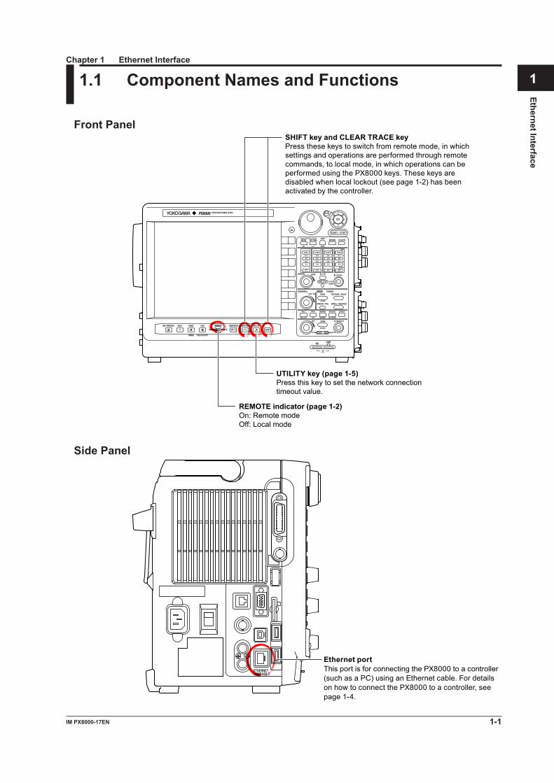
SHIFT key and CLEAR TRACE keyPress these keys to switch from remote mode, in which settings and operations are performed through remote commands, to local mode, in which operations can be performed using the PX8000 keys. These keys are disabled when local lockout (see page 1-2) has been activated by the controller.
UTILITY key (page 1-5)Press this key to set the network connection timeout value.
REMOTE indicator (page 1-2)On: Remote modeOff: Local mode
Side Panel
Ethernet port This port is for connecting the PX8000 to a controller (such as a PC) using an Ethernet cable. For details on how to connect the PX8000 to a controller, see page 1-4.
1000BASE-TETHERNET
1-2 IM PX8000-17EN
1.2 Ethernet Interface Features and Specifications
Ethernet Interface FeaturesReception FeaturesAllows you to specify the same settings that you can using the front panel keys.Receives output requests for measured and computed data, panel setting data, and error codes.
Transmission FeaturesThe PX8000 can (1) transmit measured and computed data, (2) transmit panel setting data and the status byte, and (3) error codes when errors occur.
Ethernet Interface SpecificationsNumber of ports: 1Electrical and mechanical specifications: complies with IEEE802.3Data rate: 1000 Mbps max.Simultaneous connections: 1Communication protocol: TCP/IP (VXI-11)Connector: RJ-45
Data Transfer RateThe following table contains approximations of how much time it takes for the PX8000 to transmit waveform data.Model: PX8000Controller: PC: Pentium 4 3.2 GHz, OS: Windows XPNetwork adapter: Intel PRO/1000 GT Desktop AdapterProgramming language: Visual C++
Number of Data Points Byte Data Word Data ASCII Data1000 Approx. 1 ms Approx. 1 ms Approx. 30 ms10000 Approx. 1 ms Approx. 2 ms Approx. 300 ms100000 Approx. 10 ms Approx. 11 ms Approx. 3 s1000000 Approx. 100 ms Approx. 125 ms Approx. 30 s
Switching between Remote and Local ModesSwitching from Local to Remote ModeThe PX8000 switches to remote mode when it is in local mode and it receives a :COMMunicate:REMote ON command from the PC.• The REMOTE indicator illuminates.• All keys except the SHIFT+CLEAR TRACE keys are disabled.• The local mode settings are retained even when the PX8000 switches to remote mode.
Switching from Remote to Local ModeWhen the PX8000 is in Remote mode and you press SHIFT+CLEAR TRACE, the PX8000 switches to local mode. However, this does not work if the PX8000 has received a :COMMunicate:LOCKout ON command from the PC. The PX8000 switches to local mode when it receives a :COMMunicate:REMote OFF command from the PC, regardless of the local lockout state.• The REMOTE indicator turns off.• All keys are enabled.• The settings in remote mode are retained even when the PX8000 switches to local mode.
NoteYou cannot use the Ethernet interface at the same time as other interfaces (GP-IB and USB interfaces).
1-3IM PX8000-17EN
Ethernet Interface
1.2 Ethernet Interface Features and Specifications
1
2
3
4
5
6
App
Index
Setting the Timeout ValueIf the PX8000 is not accessed within a given period of time (specified by the timeout value), it will disconnect from the network. The timeout value can be set from 0 to 3600 s. The default setting is Infinite (0 s).For instructions on how to set the timeout value, see section 1.4, “Configuring the PX8000 Ethernet Settings.”
1-4 IM PX8000-17EN
1.3 Connecting to the Ethernet Interface
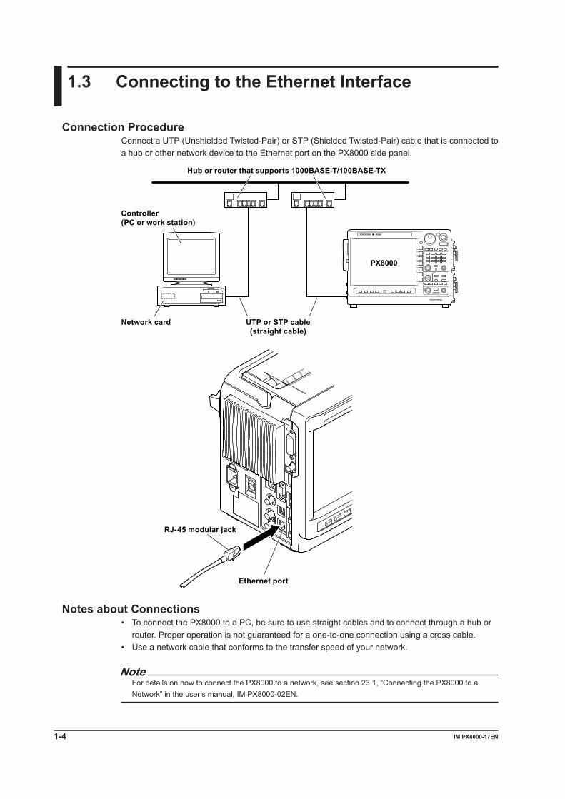
Connection ProcedureConnect a UTP (Unshielded Twisted-Pair) or STP (Shielded Twisted-Pair) cable that is connected to a hub or other network device to the Ethernet port on the PX8000 side panel.
Hub or router that supports 1000BASE-T/100BASE-TX
PX8000
Controller(PC or work station)
UTP or STP cable(straight cable)
Network card
Ethernet port
RJ-45 modular jack
Notes about Connections• To connect the PX8000 to a PC, be sure to use straight cables and to connect through a hub or
router. Proper operation is not guaranteed for a one-to-one connection using a cross cable.• Use a network cable that conforms to the transfer speed of your network.
NoteFor details on how to connect the PX8000 to a network, see section 23.1, “Connecting the PX8000 to a Network” in the user’s manual, IM PX8000-02EN.

1-5IM PX8000-17EN
Ethernet Interface
1
2
3
4
5
6
App
Index
1.4 Configuring the PX8000 Ethernet Settings
This section explains the settings listed below. You must configure these settings when controlling the PX8000 remotely through an Ethernet interface.• Network connection timeout setting
UTILITY Remote Ctrl MenuPress UTILITY and the Remote Ctrl soft key, and then the Network soft key to display the following menu.
Set the timeout value (using the jog shuttle).
NoteOnly use one communication interface: GP-IB, USB, or Network. If you send commands simultaneously from more than one communication interface, the PX8000 will not execute the commands properly.
TCP/IP SettingsTo use the Ethernet interface features, you must specify the following TCP/IP settings.• IP address• Subnet mask• Default gateway
For details on how to specify these settings, see section 23.2, “Configuring TCP/IP Settings” in the user’s manual, IM PX8000-02EN.
2-1IM PX8000-17EN
USB
Interface
1
2
3
4
5
6
App
Index
2.1 Component Names and Functions
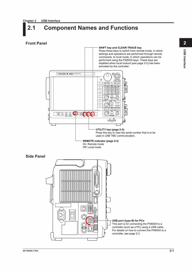
Front Panel
SHIFT key and CLEAR TRACE keyPress these keys to switch from remote mode, in which settings and operations are performed through remote commands, to local mode, in which operations can be performed using the PX8000 keys. These keys are disabled when local lockout (see page 2-2) has been activated by the controller.
UTILITY key (page 2-4)Press this key to view the serial number that is to be used in USB TMC communication.
REMOTE indicator (page 2-2)On: Remote modeOff: Local mode
Side Panel
USB port (type B) for PCs This port is for connecting the PX8000 to a controller (such as a PC) using a USB cable. For details on how to connect the PX8000 to a controller, see page 2-3.
Chapter 2 USB Interface
2-2 IM PX8000-17EN
2.2 USB Interface Features and Specifications
USB Interface FeaturesReception FeaturesAllows you to specify the same settings that you can using the front panel keys.Receives output requests for measured and computed data, panel setting data, and error codes.
Transmission FeaturesThe PX8000 can (1) transmit measured and computed data, (2) transmit panel setting data and the status byte, and (3) error codes when errors occur.
USB Interface SpecificationsElectrical and mechanical specifications: USB 2.0Connector: Type B connector (receptacle)Number of ports: 1Power supply: Self poweredSystem requirements: A PC with a USB port, running Windows 7 (32 bit), Windows Vista (32 bit),
or Windows XP (32 bit, SP2 or later). A separate device driver is required to enable the connection with the PC.
Data Transfer RateThe following table contains approximations of how much time it takes for the PX8000 to transmit waveform data.Model: PX8000Controller: PC: Pentium 4 3.2 GHz, USB 2.0 (ICH6), OS: Windows XPProgramming language: Visual C++
Number of Data Points Byte Data Word Data ASCII Data1000 Approx. 1 ms Approx. 1 ms Approx. 30 ms10000 Approx. 1 ms Approx. 2 ms Approx. 300 ms100000 Approx. 16 ms Approx. 15 ms Approx. 3 s1000000 Approx. 111 ms Approx. 170 ms Approx. 30 s
Switching between Remote and Local ModesSwitching from Local to Remote ModeThe PX8000 switches to remote mode when it is in local mode and it receives a :COMMunicate:REMote ON command from the PC.• The REMOTE indicator illuminates.• All keys except the SHIFT+CLEAR TRACE keys are disabled.• The local mode settings are retained even when the PX8000 switches to remote mode.
Switching from Remote to Local ModeWhen the PX8000 is in Remote mode and you press SHIFT+CLEAR TRACE, the PX8000 switches to local mode. However, this does not work if the PX8000 has received a :COMMunicate:LOCKout ON command from the PC. The PX8000 switches to local mode when it receives a :COMMunicate:REMote OFF command from the PC, regardless of the local lockout state.• The REMOTE indicator turns off.• All keys are enabled.• The settings in remote mode are retained even when the PX8000 switches to local mode.
NoteYou cannot use the USB interface at the same time as other interfaces (GP-IB and Ethernet interfaces).
2-3IM PX8000-17EN
USB
Interface
1
2
3
4
5
6
App
Index
2.3 Connecting to the USB Interface
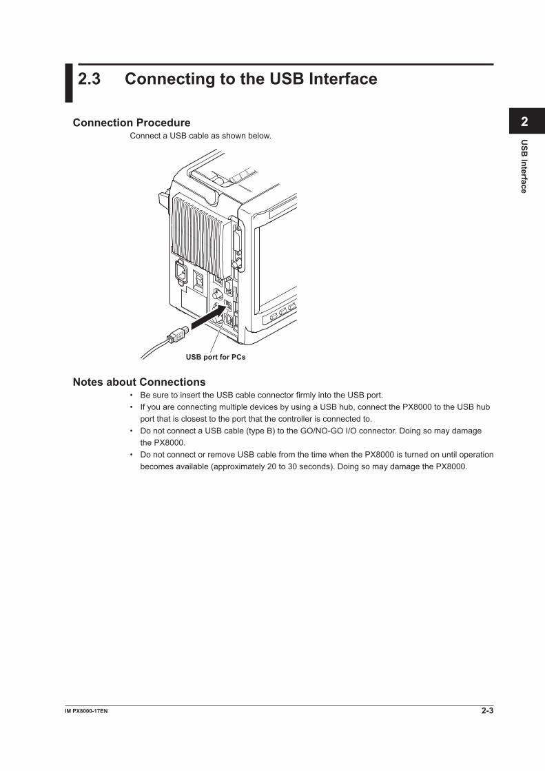
Connection ProcedureConnect a USB cable as shown below.
USB port for PCs
Notes about Connections• Be sure to insert the USB cable connector firmly into the USB port.• If you are connecting multiple devices by using a USB hub, connect the PX8000 to the USB hub
port that is closest to the port that the controller is connected to.• Do not connect a USB cable (type B) to the GO/NO-GO I/O connector. Doing so may damage
the PX8000.• Do not connect or remove USB cable from the time when the PX8000 is turned on until operation
becomes available (approximately 20 to 30 seconds). Doing so may damage the PX8000.
2-4 IM PX8000-17EN
2.4 Configuring the PX8000 USB Settings
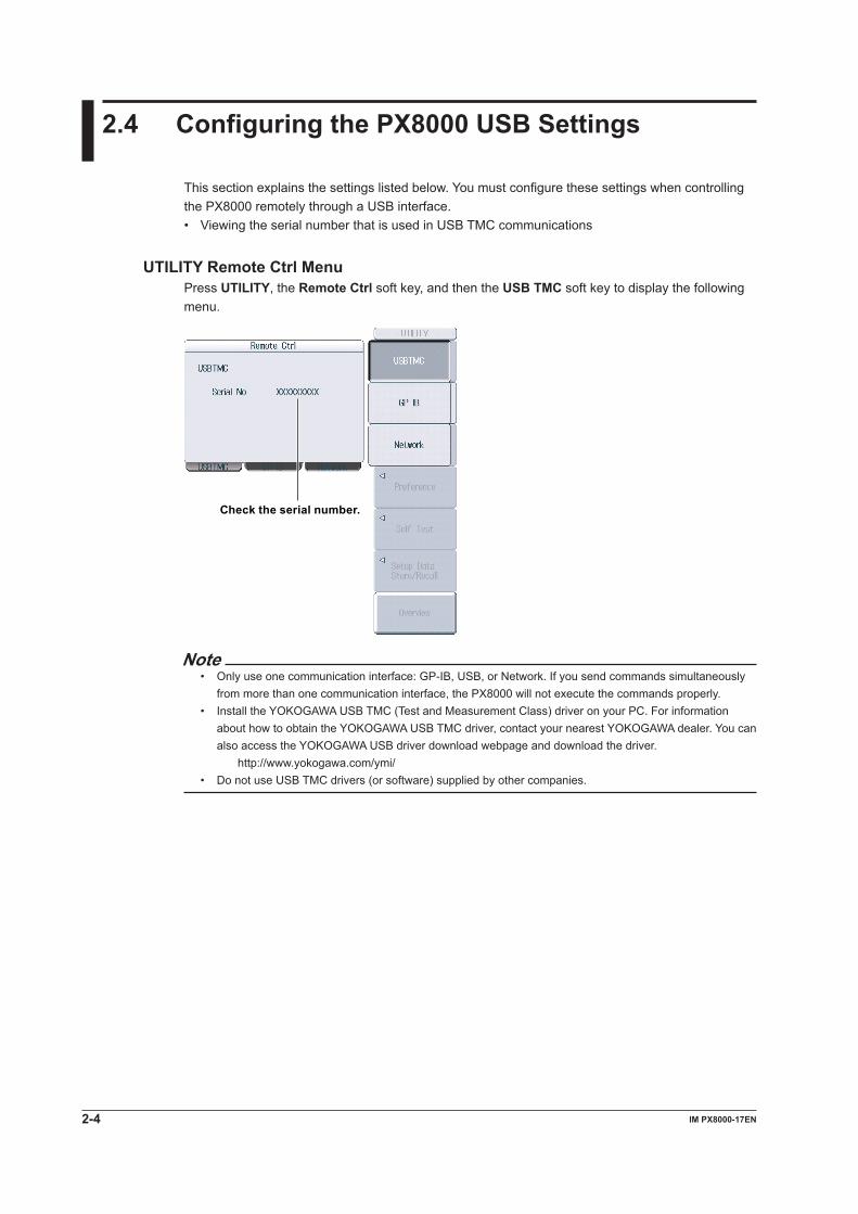
This section explains the settings listed below. You must configure these settings when controlling the PX8000 remotely through a USB interface.• Viewing the serial number that is used in USB TMC communications
UTILITY Remote Ctrl MenuPress UTILITY, the Remote Ctrl soft key, and then the USB TMC soft key to display the following menu.
Check the serial number.
Note• Only use one communication interface: GP-IB, USB, or Network. If you send commands simultaneously
from more than one communication interface, the PX8000 will not execute the commands properly.• Install the YOKOGAWA USB TMC (Test and Measurement Class) driver on your PC. For information
about how to obtain the YOKOGAWA USB TMC driver, contact your nearest YOKOGAWA dealer. You can also access the YOKOGAWA USB driver download webpage and download the driver.
http://www.yokogawa.com/ymi/• Do not use USB TMC drivers (or software) supplied by other companies.
3-1IM PX8000-17EN
GP-IB
Interface
1
2
3
4
5
6
App
Index
3.1 Component Names and Functions
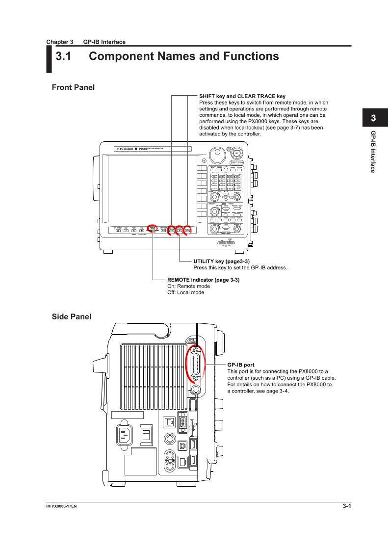
Front Panel
SHIFT key and CLEAR TRACE keyPress these keys to switch from remote mode, in which settings and operations are performed through remote commands, to local mode, in which operations can be performed using the PX8000 keys. These keys are disabled when local lockout (see page 3-7) has been activated by the controller.
UTILITY key (page3-3)Press this key to set the GP-IB address.
REMOTE indicator (page 3-3)On: Remote modeOff: Local mode
Side Panel
GP-IB port This port is for connecting the PX8000 to a controller (such as a PC) using a GP-IB cable. For details on how to connect the PX8000 to a controller, see page 3-4.
GP-IB(IEEE488)
Chapter 3 GP-IB Interface
3-2 IM PX8000-17EN
3.2 GP-IB Interface Features and Specifications
GP-IB Interface FeaturesListener Capabilities• Allows you to specify the same PX8000 settings that you can using the front panel keys. You
cannot turn the power on and off or change communication settings.• Receives output requests for measured and computed data, panel setting data, and error codes.• Receives status report commands and other commands.
Talker CapabilitiesThe PX8000 can (1) transmit measured and computed data, (2) transmit panel setting data and the status byte, and (3) error codes when errors occur.
NoteTalk-only, listen-only, and controller capabilities are not available on the PX8000.
GP-IB Interface SpecificationsSupported Devices: National Instruments Corporation • PCI-GPIB or PCI-GPIB+ • PCIe-GPIB or PCIe-GPIB+ • PCMCIA-GPIB or PCMCIA-GPIB+ • GPIB-USB-HS Driver NI-488.2M Version 1.60 or laterElectrical and mechanical specifications: IEEE St’d 488-1978Functional specifications: See the table below.Protocol: IEEE St’d 488.2-1992Code: ISO (ASCII) codesMode: Addressable modeAddress setup: Press UTILITY and then the Remote Ctrl soft key. Then, set the network
interface (Device) to GP-IB and the address to a number from 0 to 30.Clearing remote mode: Press SHIFT+CLEAR TRACE to switch the PX8000 to local mode.
These keys are disabled when local lockout has been activated by a controller.
Functional SpecificationsFunction Subset Name DescriptionSource handshaking SH1 Full source handshaking capabilityAcceptor handshaking AH1 Full acceptor handshaking capabilityTalker T6 Basic talker capability, serial polling, untalk on MLA (My Listen
Address), and no talk-only capabilityListener L4 Basic listener capability, unlisten on MTA (My Talk Address), and
no listen-only capabilityService request SR1 Full service request capabilityRemote local RL1 Full remote/local capabilityParallel polling PP0 No parallel poll capabilityDevice clear DC1 Full device clear capabilityDevice trigger DT0 No device trigger capabilityController C0 No controller capabilityElectric characteristics E1 Open collector
3-3IM PX8000-17EN
GP-IB
Interface
1
2
3
4
5
6
App
Index
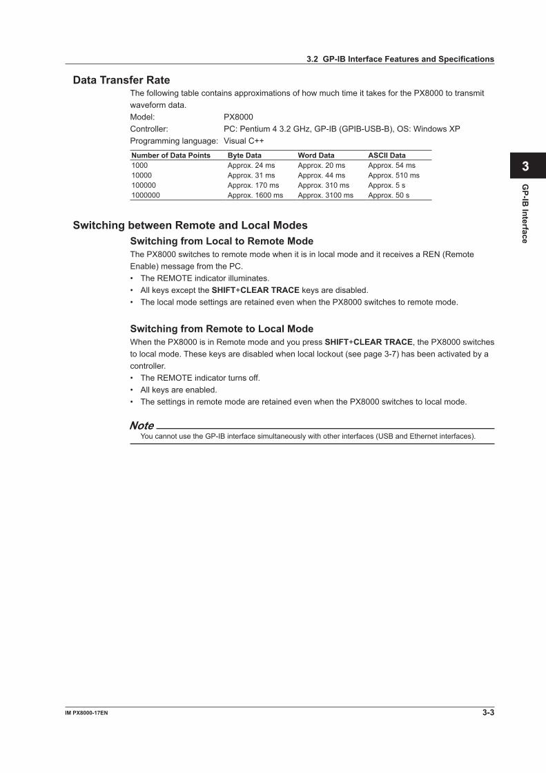
Data Transfer RateThe following table contains approximations of how much time it takes for the PX8000 to transmit waveform data.Model: PX8000Controller: PC: Pentium 4 3.2 GHz, GP-IB (GPIB-USB-B), OS: Windows XPProgramming language: Visual C++
Number of Data Points Byte Data Word Data ASCII Data1000 Approx. 24 ms Approx. 20 ms Approx. 54 ms10000 Approx. 31 ms Approx. 44 ms Approx. 510 ms100000 Approx. 170 ms Approx. 310 ms Approx. 5 s1000000 Approx. 1600 ms Approx. 3100 ms Approx. 50 s
Switching between Remote and Local ModesSwitching from Local to Remote ModeThe PX8000 switches to remote mode when it is in local mode and it receives a REN (Remote Enable) message from the PC.• The REMOTE indicator illuminates.• All keys except the SHIFT+CLEAR TRACE keys are disabled.• The local mode settings are retained even when the PX8000 switches to remote mode.
Switching from Remote to Local ModeWhen the PX8000 is in Remote mode and you press SHIFT+CLEAR TRACE, the PX8000 switches to local mode. These keys are disabled when local lockout (see page 3-7) has been activated by a controller.• The REMOTE indicator turns off.• All keys are enabled.• The settings in remote mode are retained even when the PX8000 switches to local mode.
NoteYou cannot use the GP-IB interface simultaneously with other interfaces (USB and Ethernet interfaces).
3.2 GP-IB Interface Features and Specifications
3-4 IM PX8000-17EN
3.3 Connecting to the GP-IB Interface
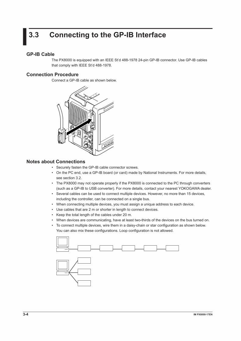
GP-IB CableThe PX8000 is equipped with an IEEE St’d 488-1978 24-pin GP-IB connector. Use GP-IB cables that comply with IEEE St’d 488-1978.
Connection ProcedureConnect a GP-IB cable as shown below.
Notes about Connections• Securely fasten the GP-IB cable connector screws.• On the PC end, use a GP-IB board (or card) made by National Instruments. For more details,
see section 3.2.• The PX8000 may not operate properly if the PX8000 is connected to the PC through converters
(such as a GP-IB to USB converter). For more details, contact your nearest YOKOGAWA dealer.• Several cables can be used to connect multiple devices. However, no more than 15 devices,
including the controller, can be connected on a single bus.• When connecting multiple devices, you must assign a unique address to each device.• Use cables that are 2 m or shorter in length to connect devices.• Keep the total length of the cables under 20 m.• When devices are communicating, have at least two-thirds of the devices on the bus turned on.• To connect multiple devices, wire them in a daisy-chain or star configuration as shown below.
You can also mix these configurations. Loop configuration is not allowed.
3-5IM PX8000-17EN
GP-IB
Interface
1
2
3
4
5
6
App
Index
CAUTIONBe sure to turn off the PC and this instrument before you connect or remove communication cables. Otherwise, erroneous operation may result, or the internal circuitry may break.
French
ATTENTIONVeiller à mettre le PC et l’instrument hors tension avant de brancher ou de débrancher les câbles de communication, pour éviter de provoquer des dysfonctionnements ou des courts-circuits internes.
3.3 Connecting to the GP-IB Interface
3-6 IM PX8000-17EN
3.4 Configuring the PX8000 GP-IB Settings
This section explains the settings listed below. You must configure these settings when controlling the PX8000 remotely through a GP-IB interface.• GP-IB address
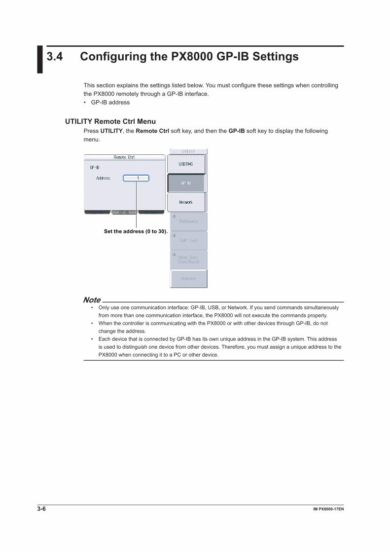
UTILITY Remote Ctrl MenuPress UTILITY, the Remote Ctrl soft key, and then the GP-IB soft key to display the following menu.
Set the address (0 to 30).
Note• Only use one communication interface: GP-IB, USB, or Network. If you send commands simultaneously
from more than one communication interface, the PX8000 will not execute the commands properly.• When the controller is communicating with the PX8000 or with other devices through GP-IB, do not
change the address.• Each device that is connected by GP-IB has its own unique address in the GP-IB system. This address
is used to distinguish one device from other devices. Therefore, you must assign a unique address to the PX8000 when connecting it to a PC or other device.
3-7IM PX8000-17EN
GP-IB
Interface
1
2
3
4
5
6
App
Index
3.5 Responses to Interface Messages
Responses to Interface MessagesResponses to Uni-Line Messages• IFC (Interface Clear) Clears the talker and listener functions. Stops data transmission if it is in progress.
• REN (Remote Enable) Switches between remote and local modes.
IDY (Identify) is not supported.
Responses to Multi-Line Messages (Address commands)• GTL (Go To Local) Switches to local mode.
• SDC (Selected Device Clear)• Clears the program message (command) being received and the output queue (see page
6-6).• Discards *OPC and *OPC? commands that are being executed.• Immediately aborts *WAI and COMMunicate:WAIT.
PPC (Parallel Poll Configure), GET (Group Execute Trigger), and TCT (Take Control) are not supported.
Responses to Multi-Line Messages (Universal commands)• LLO (Local Lockout) Disables the CLEAR TRACE key on the front panel to prohibit switching to the local mode.
• DCL (Device Clear) Performs the same operation as SDC.
• SPE (Serial Poll Enable) Sets the talker function on all devices on the bus to serial polling mode. The controller will poll
each device in order.
• SPD (Serial Poll Disable) Clears the talker function’s serial poll mode on all devices on the bus.
PPU (Parallel Poll Unconfigure) is not supported.
What Are Interface Messages?Interface messages are commands that a controller transmits. They are also referred to as interface commands or bus commands. They are classified as follows:
Uni-line MessagesUni-line messages are sent over a single control line. The following three terminators are available.• IFC (Interface Clear)• REN (Remote Enable)• IDY (Identify)
3-8 IM PX8000-17EN
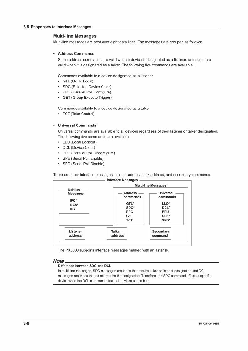
Multi-line MessagesMulti-line messages are sent over eight data lines. The messages are grouped as follows:
• Address Commands Some address commands are valid when a device is designated as a listener, and some are
valid when it is designated as a talker. The following five commands are available.
Commands available to a device designated as a listener• GTL (Go To Local)• SDC (Selected Device Clear)• PPC (Parallel Poll Configure)• GET (Group Execute Trigger)
Commands available to a device designated as a talker• TCT (Take Control)
• Universal Commands Universal commands are available to all devices regardless of their listener or talker designation.
The following five commands are available.• LLO (Local Lockout)• DCL (Device Clear)• PPU (Parallel Poll Unconfigure)• SPE (Serial Poll Enable)• SPD (Serial Poll Disable)
There are other interface messages: listener-address, talk-address, and secondary commands.
Interface Messages
Uni-line Messages Address
commands Universal commands
IFC*REN*IDY
GTL*SDC*PPCGETTCT
LLO*DCL*PPUSPE*SPD*
Listener address
Talker address
Secondary command
Multi-line Messages
The PX8000 supports interface messages marked with an asterisk.
NoteDifference between SDC and DCLIn multi-line messages, SDC messages are those that require talker or listener designation and DCL messages are those that do not require the designation. Therefore, the SDC command affects a specific device while the DCL command affects all devices on the bus.
3.5 Responses to Interface Messages
4-1IM PX8000-17EN
Programm
ing Overview
1
2
3
4
5
6
App
Index
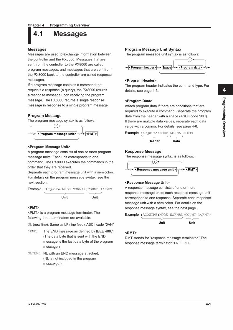
Program Message Unit SyntaxThe program message unit syntax is as follows:
,
<Program header> <Program data>Space
<Program Header>The program header indicates the command type. For details, see page 4-3.
<Program Data>Attach program data if there are conditions that are required to execute a command. Separate the program data from the header with a space (ASCII code 20H). If there are multiple data values, separate each data value with a comma. For details, see page 4-6.
:ACQuire:MODE NORMal<PMT>Example
DataHeader
Response MessageThe response message syntax is as follows:
<RMT>
;
<Response message unit>
<Response Message Unit>A response message consists of one or more response message units; each response message unit corresponds to one response. Separate each response message unit with a semicolon. For details on the response message syntax, see the next page.
Unit Unit
:ACQUIRE:MODE NORMAL;COUNT 1<RMT>Example
<RMT>RMT stands for “response message terminator.” The response message terminator is NL^END.
MessagesMessages are used to exchange information between the controller and the PX8000. Messages that are sent from the controller to the PX8000 are called program messages, and messages that are sent from the PX8000 back to the controller are called response messages.If a program message contains a command that requests a response (a query), the PX8000 returns a response message upon receiving the program message. The PX8000 returns a single response message in response to a single program message.
Program MessageThe program message syntax is as follows:
<PMT>
;
<Program message unit>
<Program Message Unit>A program message consists of one or more program message units. Each unit corresponds to one command. The PX8000 executes the commands in the order that they are received.Separate each program message unit with a semicolon.For details on the program message syntax, see the next section.
Example
Unit Unit
:ACQuire:MODE NORMal;COUNt 1<PMT>
<PMT><PMT> is a program message terminator. The following three terminators are available.
NL (new line): Same as LF (line feed). ASCII code “0AH”
^END: The END message as defined by IEEE 488.1 (The data byte that is sent with the END
message is the last data byte of the program message.)
NL^END: NL with an END message attached. (NL is not included in the program
messaxge.)
4.1 MessagesChapter 4 Programming Overview
4-2 IM PX8000-17EN
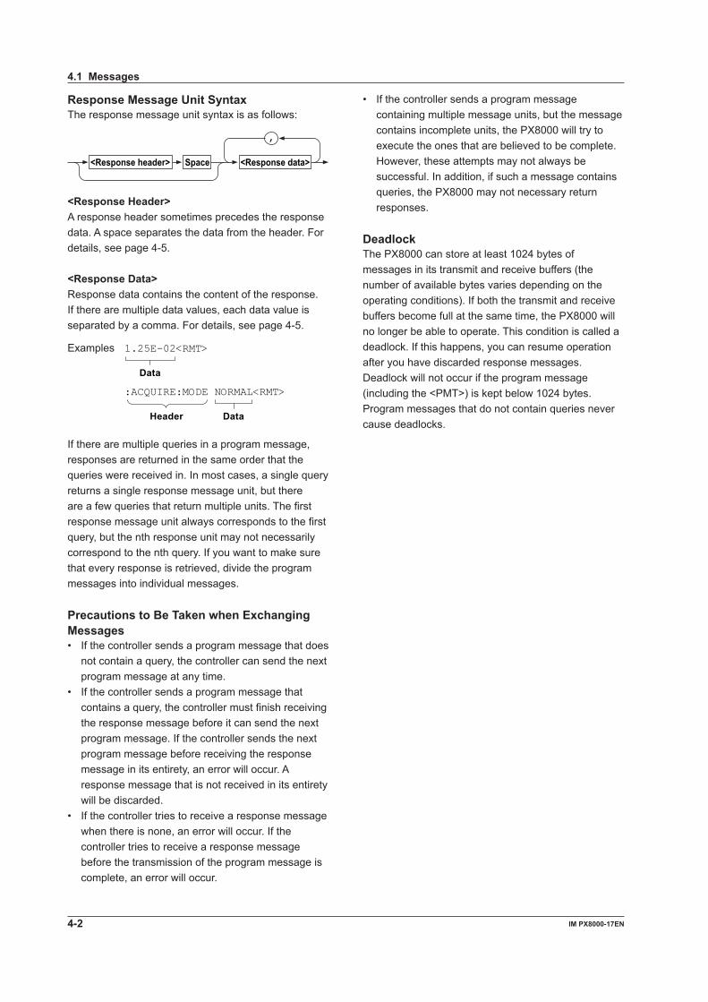
Response Message Unit SyntaxThe response message unit syntax is as follows:
,
<Response header> <Response data>Space
<Response Header>A response header sometimes precedes the response data. A space separates the data from the header. For details, see page 4-5.
<Response Data>Response data contains the content of the response. If there are multiple data values, each data value is separated by a comma. For details, see page 4-5.
1.25E-02<RMT>
Data
:ACQUIRE:MODE NORMAL<RMT>
DataHeader
Examples
If there are multiple queries in a program message, responses are returned in the same order that the queries were received in. In most cases, a single query returns a single response message unit, but there are a few queries that return multiple units. The first response message unit always corresponds to the first query, but the nth response unit may not necessarily correspond to the nth query. If you want to make sure that every response is retrieved, divide the program messages into individual messages.
Precautions to Be Taken when Exchanging Messages• If the controller sends a program message that does
not contain a query, the controller can send the next program message at any time.
• If the controller sends a program message that contains a query, the controller must finish receiving the response message before it can send the next program message. If the controller sends the next program message before receiving the response message in its entirety, an error will occur. A response message that is not received in its entirety will be discarded.
• If the controller tries to receive a response message when there is none, an error will occur. If the controller tries to receive a response message before the transmission of the program message is complete, an error will occur.
• If the controller sends a program message containing multiple message units, but the message contains incomplete units, the PX8000 will try to execute the ones that are believed to be complete. However, these attempts may not always be successful. In addition, if such a message contains queries, the PX8000 may not necessary return responses.
DeadlockThe PX8000 can store at least 1024 bytes of messages in its transmit and receive buffers (the number of available bytes varies depending on the operating conditions). If both the transmit and receive buffers become full at the same time, the PX8000 will no longer be able to operate. This condition is called a deadlock. If this happens, you can resume operation after you have discarded response messages.Deadlock will not occur if the program message (including the <PMT>) is kept below 1024 bytes. Program messages that do not contain queries never cause deadlocks.
4.1 Messages
4-3IM PX8000-17EN
Programm
ing Overview
1
2
3
4
5
6
App
Index
When Concatenating Commands• Command Groups A command group is a group of commands that
have common compound headers arranged in a hierarchy. A command group may contain sub-groups.Example Group of commands related to acquisition :ACQuire:AVERage:COUNt :ACQuire:AVERage:EWEight :ACQuire:CLOCk :ACQuire:COUNt :ACQuire:LOGGer :ACQuire:MODE :ACQuire:PROTate :ACQuire:RLENgth
• When Concatenating Commands of the Same Group
The PX8000 stores the hierarchical level of the command that is currently being executed and processes the next command on the assumption that it belongs to the same level. Therefore, the common header section can be omitted for commands that belong to the same group.Example :ACQuire:MODE NORMal;
COUNt 1<PMT>
• When Concatenating Commands of Different Groups
If the subsequent command does not belong to the same group, place a colon in front of the header (cannot be omitted).Example :ACQuire:MODE NORMal;:DISPlay:
FORMat SINGle<PMT>
• When Concatenating Simple Headers If a simple header follows another command, place
a colon in front of the simple header (cannot be omitted).Example :ACQuire:MODE NORMal;:
STARt<PMT>
• When Concatenating Common Commands Common commands that are defined in IEEE
488.2-1992 are independent of hierarchy. There is no need to use a colon.Example :ACQuire:MODE NORMal;*CLS;
COUNt 1<PMT>
• When Separating Commands with <PMT> If you separate two commands with a terminator,
two program messages will be sent. Therefore, the common header must be specified for each command even if commands belonging to the same command group are being concatenated.Example :ACQuire:MODE NORMal<PMT>:
ACQuire:COUNt 1<PMT>
4.2 Commands
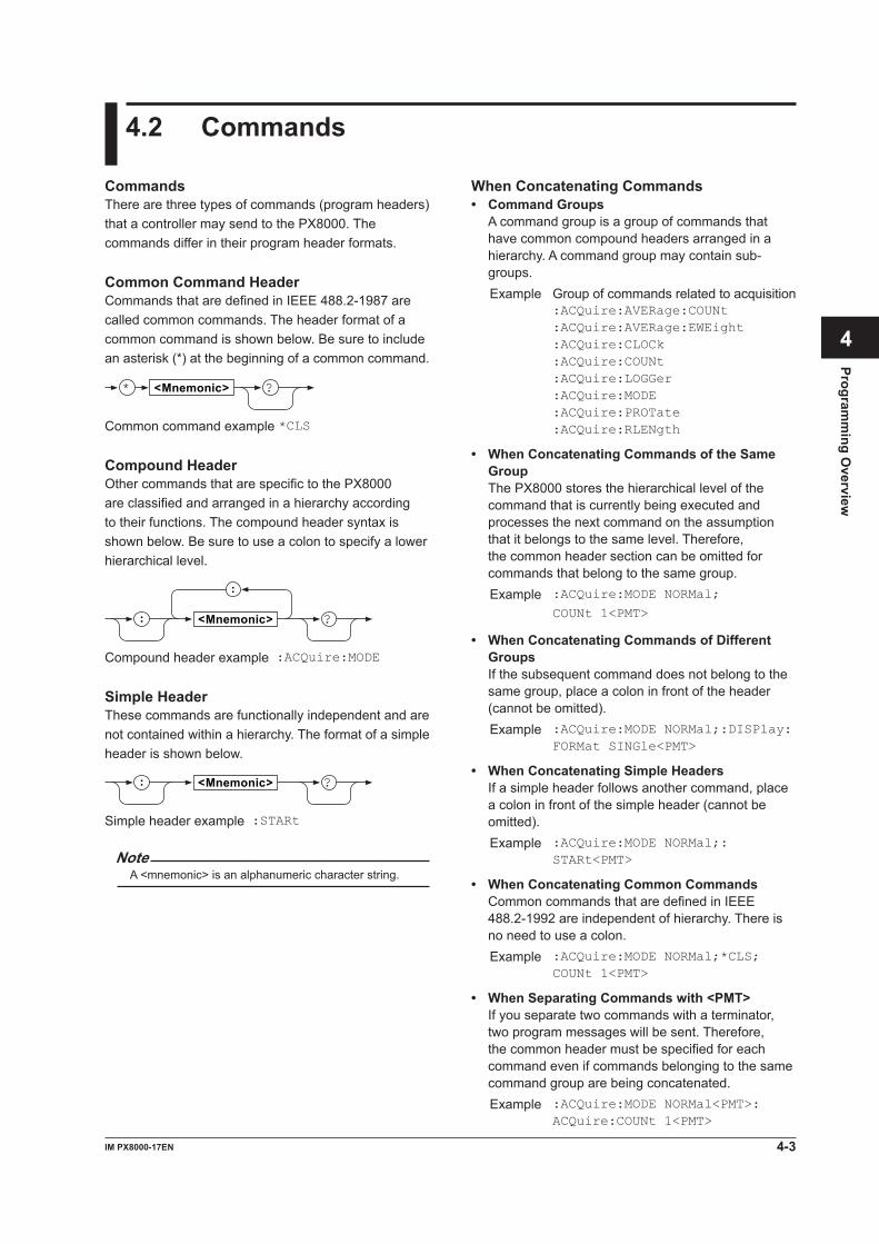
CommandsThere are three types of commands (program headers) that a controller may send to the PX8000. The commands differ in their program header formats.
Common Command HeaderCommands that are defined in IEEE 488.2-1987 are called common commands. The header format of a common command is shown below. Be sure to include an asterisk (*) at the beginning of a common command.
* <Mnemonic> ?
Common command example *CLS
Compound HeaderOther commands that are specific to the PX8000 are classified and arranged in a hierarchy according to their functions. The compound header syntax is shown below. Be sure to use a colon to specify a lower hierarchical level.
:
<Mnemonic> ?:
Compound header example :ACQuire:MODE
Simple HeaderThese commands are functionally independent and are not contained within a hierarchy. The format of a simple header is shown below.
<Mnemonic> ?:
Simple header example :STARt
Note A <mnemonic> is an alphanumeric character string.
4-4 IM PX8000-17EN
Upper-Level QueryAn upper-level query is a query that is made by appending a question mark to a command higher in the group. The controller can receive all of the settings in a group collectively by executing a highest-level query. Some upper-level queries of a group, which may be comprised of more than three hierarchical levels, can cause the PX8000 to transmit all the lower level settings.
Example : CHANnel1?<PMT> -> :CHANNEL1:DISPLAY 1;
LABEL "U1";VOLTAGE:AUTO 0;
OFFSET 0.00000E+00;POSITION 0.00;
SCALE 200.000E+00,-200.000E+00;
VARIABLE 0;ZOOM 1.000
The response to an upper-level query can be sent back to the PX8000 as a program message. This enables the settings that were present when the upper-level query was made to be reproduced later on. However, some upper-level queries do not return setup data that is not currently in use. Exercise caution because not all of a group’s information is necessarily returned in a response.
Header Interpretation RulesThe PX8000 interprets the header that it receives according to the rules below.
• Mnemonics are not case sensitive. Example CURSor can be written as cursor or
Cursor.
• The lower-case characters can be omitted. Example CURSor can be written as CURSO or
CURS.
• The question mark at the end of a header indicates that it is a query. You cannot omit the question mark.
Example The shortest abbreviation for CURSor? is CURS?.
• If the <x> (value) at the end of a mnemonic is omitted, it is interpreted as a 1.
Example If you write CHAN for CHANnel<x>, CHANnel1 is specified.
• Parts of commands and parameters enclosed in square brackets ([ ]) can be omitted.
Example TRIGger[:SIMPle]:LEVel can be written as TRIG:LEV.
However, the last section enclosed in square brackets cannot be omitted in an upper-level query.
Example TRIGger? and TRIGger:SIMPle? are different queries.
4.2 Commands
4-5IM PX8000-17EN
Programm
ing Overview
1
2
3
4
5
6
App
Index
4.3 Response
ResponseWhen the controller sends a query with a question mark, the PX8000 returns a response message to the query. The PX8000 returns response messages in one of the following two forms.
• Response Consisting of a Header and Data Responses that can be used as program messages
without any changes are returned with command headers attached.
Example :ACQUire:MODE?<PMT> -> :ACQUIRE:MODE NORMAL<RMT>
• Response Only Consisting of Data Responses that cannot be used as program
messages unless changes are made (query-only commands) are returned without headers. However, there are query-only commands whose responses the PX8000 will attach headers to.
Example [:INPut]:POVer?<PMT> -> 0<RMT>
If You Want the PX8000 to Return Responses without HeadersYou can configure the PX8000 so that even responses that have both headers and data are returned without headers. Use the COMMunicate:HEADer command for this purpose.
Abbreviated FormThe PX8000 normally returns response headers with the lower-case section removed. You can configure the PX8000 so that full headers are returned. Use the COMMunicate:VERBose command for this purpose. The sections enclosed in square brackets ([ ]) are also omitted in the abbreviated form.
4-6 IM PX8000-17EN
4.4 Data
• If a value outside the setting range is entered, the value is adjusted to the closest value within the range.
• If a value has more significant digits than are available, the value will be rounded.
<Voltage>, <Current>, <Power>, <Time>, and <Frequency><Voltage>, <Current>, <Power>, <Time>, and <Frequency> indicate decimal values that have physical significance. A <Multiplier> or <Unit> can be attached to the <NRf> form that was described earlier. The following types of expressions are possible.
Form Example<NRf><Multiplier><Unit> 5MV<NRf><Unit> 5E-3V<NRf> 5E-3
<Multiplier><Multipliers> that you can use are indicated in the following table.
Symbol Word MultiplierEX Exa 1018
PE Peta 1015
T Tera 1012
G Giga 109
MA Mega 106
K Kilo 103
M Milli 10–3
U Micro 10–6
N Nano 10–9
P Pico 10–12
F Femto 10–15
A Atto 10–18
<Unit><Units> that you can use are indicated in the following table.
Symbol Word DescriptionV Volt VoltageA Ampere CurrentW Watt PowerS Second TimeHZ Hertz FrequencyMHZ Megahertz Frequency
• <Multiplier> and <Unit> are not case sensitive.• “U”isusedtoindicatemicro(“μ”).• “MA” is used for Mega to distinguish it from Milli.
Megahertz, which is expressed as “MHZ,” is an exception. Therefore, “M (Milli)” cannot be used for frequencies.
• If both <Multiplier> and <Unit> are omitted, the default unit is used.
• Response messages are always expressed in the <NR3> form. Response messages are returned using the default unit without the <Multiplier> or <Unit>.
DataData contains conditions and values that are written after the header. A space separates the data from the header. Data is grouped as follows:
Data Description<Decimal> A value expressed in decimal notation
Example Probe attenuation for CH1 -> CHANnel1:PROBe 100
<Voltage>, <Current>, <Power>, <Time>, <Frequency>
A physical value
Example Time-axis range -> TIMebase:TDIV 1US
<Register> A register value expressed as binary, octal, decimal or hexadecimalExample Extended event register value -> STATUS:EESE #HFE
<Character data> Predefined character string (mnemonic). Select from the available strings in braces.Example Select the input coupling of CH1 -> CHANnel1:COUPling {AC|DC| GND}
<Boolean> Indicates on and off. Specify ON, OFF, or a valueExample Turn on the CH1 display -> CHANnel1:DISPlay ON
<String data> User-defined stringExample Comment attached to screen data output -> HCOPy:COMMent "ABCDEF"
<Filename> Indicates a file name.Example Save file name -> FILE:SAVE:NAME "CASE1"
<Block data> Data that contains 8-bit valuesExample Response to acquired waveform data -> #800000010ABCDEFGHIJ
<Decimal><Decimal> indicates a value expressed as a decimal number, as shown in the table below. Decimal values are written in the NR form as specified in ANSI X3.42-1975.
Symbol Description Examples<NR1> Integer 125 -1 +1000<NR2> Fixed point number 125.0 -.90 +001.<NR3> Floating-point number 125.0E+0 -9E-1 +.1E4<NRf> Any form from <NR1> to <NR3>
• The PX8000 can receive decimal values that are sent from the controller in any form, from <NR1> to <NR3>. This is expressed as <NRf>.
• The PX8000 returns a response to the controller in one of the forms from <NR1> to <NR3> depending on the query. The same form is used regardless of the size of the value.
• For the <NR3> form, the plus sign after the “E” can be omitted. You cannot omit the minus sign.
4-7IM PX8000-17EN
Programm
ing Overview
1
2
3
4
5
6
App
Index
two consecutive quotation marks (""). This rule also applies to single quotation marks.
• A response message is always enclosed in double quotation marks (").
• <String data> is any character string. Therefore, the PX8000 assumes that the remaining program message units are part of the character string if no single (') or double quotation mark (") is encountered. As a result, no error is detected if a quotation mark is omitted.
<Filename><Filename> is data that indicates a file name. The following types of expressions are possible.
Form Example{<NRf>|<Character data>|<String data>} 1 CASE "CASE"
<NRf> is rounded to an 8-digit integer and converted to ASCII code. The result is the file name. Negative values are not allowed.
Example 1 becomes "00000001"
• The first 12 characters of <character data> or the first 16 characters of <string data> are the file name.
• Response messages are always expressed in the <string data> form.
• For information about the number of characters in a file name expressed in the <string data> form, see the features guide, IM PX8000-01EN.
<Block data><Block data> is any 8-bit data. It is only used in response messages on the PX8000. The syntax is as follows:
Form #N<N-digit decimal number><Data byte sequence>Example #800000010ABCDEFGHIJ
• #N Indicates that the data is <block data>.“N” indicates
the number of succeeding data bytes (digits) in ASCII code.
• <N-digit decimal number> Indicates the number of bytes of data.
Example 00000010 = 10 bytes
• <Data byte sequence> Expresses the actual data.
Example ABCDEFGHIJ
• Data is comprised of 8-bit values (0 to 255). This means that the ASCII code “0AH” which stands for “NL” can also be included in the data. Hence, care must be taken when programming the controller.
<Register><Register> is an integer that can be expressed in decimal, hexadecimal, octal, or binary notation. It is used when each bit of the value has a particular meaning. The following types of expressions are possible.
Form Example<NRf> 1#H< Hexadecimal value made up of the digits 0
to 9 and A to F>#H0F
#Q<Octal value made up of the digits 0 to 7> #Q777#B<Binary value made up of the digits 0 and 1> #B001100
• <Register> is not case sensitive.• Response messages are always expressed in the
<NR1> form.
<Character Data><Character data> is a predefined character string (mnemonics). It is mainly used to indicate that an option listed as a character string in braces must be selected and entered. The data interpretation rules are the same as those described in “Header Interpretation Rules” on page 4-4.
Form Example{AC|DC|GND} AC
• As with the header, the COMMunicate:VERBose command can be used to select whether to return the response in the full form or in the abbreviated form.
• The COMMunicate:HEADer setting does not affect <character data>.
<Boolean><Boolean> is data that indicates on or off. The following types of expressions are possible.
Form Examples{ON|OFF|<NRf>} ON OFF 1 0
• When <Boolean> is expressed in the <NRf> form, OFF is selected if the rounded integer value is 0, and ON is selected for all other cases.
• A response message is always returned with a 1 if the value is ON and with a 0 if the value is OFF.
<String data><String data> is not a predefined character string like <character data>. It can be any character string. The character string must be enclosed in single quotation marks (') or double quotation marks (").
Form Examples<String data> 'ABC' "IEEE488.2-1987"
• If a character string contains a double quotation mark ("), the double quotation mark is expressed as
4.4 Data
4-8 IM PX8000-17EN
4.5 Synchronization with the Controller
• Using the COMMunicate:OVERlap command The COMMunicate:OVERlap command enables (or
disables) overlapping.
Example :COMMunicate:OVERlap #HFFBF;:FILE:LOAD:SETup:EXECute "CASE1";:
INPut:VOLTage:RANGe:
ELEMent1?<PMT>
COMMunicate:OVERlap #HFFBF enables overlapping for commands other than media access. Because overlapping of file loading is disabled, FILE:LOAD:SETup:EXECute "CASE1" operates in the same way as a sequential command. Thus, INPut:VOLTage:RANGe:ELEMent1? is not executed until file loading is completed.
• Using the *OPC Command The *OPC command sets the OPC bit, which is bit
0 in the standard event register (see page 6-4), to 1 when the overlapping is completed.
Example :COMMunicate:OPSE #H0040;*ESE 1;
*ESR?;*SRE 32;:FILE:LOAD:SETup:
EXECute "CASE1";*OPC<PMT>
(Read the response to *ESR?) (Wait for a service request) :INPut:VOLTage:RANGe:
ELEMent1?<PMT>
The COMMunicate:OPSE command is used to select which command to apply *OPC to. Here, it is applied to the media access command.
*ESE 1 and *SRE 32 indicate that a service request is only generated when the OPC bit is 1.
*ESR? clears the standard event register. In the example above, INPut:VOLTage:RANGe:
ELEMent1? is not executed until a service request is generated.
Overlap Commands and Sequential CommandsThere are two types of commands: overlap and sequential. The execution of one overlap command can start before the execution of the previous overlap command is completed.If you specify the voltage range and send the next program message to query the result, the PX8000 always returns the most recent setting (1000 V in this case).
:INPut:VOLTage:RANGe;ELEMent1 1000V;ELEMent?<PMT>
This is because the next command is forced to wait until the processing of INPut:VOLTage:RANGe; ELEMent1 is completed. This type of command is called a sequential command.Let us assume you send the next program message when you want to load a file and query the voltage range of the result.
:FILE:LOAD:SETup:EXECute "CASE1";: INPut:VOLTage:RANGe:ELEMent1?
In this case, INPut:VOLTage:RANGe;ELEMent1? is executed before the loading of the file is completed, and the voltage range that is returned is the value before the file is loaded.Overlapping refers to the act of executing the next command before the processing of the current command is completed, such as in the command FILE:LOAD:SETup:EXECute "CASE1". A command that operates in this way is called an overlap command.You can prevent overlapping by using the following methods.
Synchronizing to Overlap Commands• Using a *WAI Command A *WAI command holds the subsequent commands
until the overlap command is completed.
Example :COMMunicate:OPSE #H0040;:FILE:LOAD:SETup:EXECute "CASE1"; *WAI;:INPut:VOLTage:RANGe:ELEMent1?<PMT>
The COMMunicate:OPSE command is used to select which command to apply *WAI to. Here, it is applied to the media access command.
*WAI is executed before INPut:VOLTage:RANGe:ELEMent1?, so INPut:VOLTage:RANGe:ELEMent1? is not executed until the file loading is completed.
4-9IM PX8000-17EN
Programm
ing Overview
1
2
3
4
5
6
App
Index
• Using the *OPC? Query The *OPC? query generates a response when an
overlapping operation is completed.
Example :COMMunicate:OPSE #H0040;:FILE:LOAD:SETup:EXECute "CASE1"; *OPC?<PMT>
(Read the response to *OPC?) :INPut:VOLTage:RANGe:
ELEMent1?<PMT>
The COMMunicate:OPSE command is used to select which command to apply *OPC? to. Here, it is applied to the media access command.
Because *OPC? does not generate a response until the overlapping operation is completed, the file loading will have been completed by the time the response to *OPC? is read.
Note Most commands are sequential commands. Overlap
commands are indicated as such in chapter 5. All other commands are sequential commands.
Achieving Synchronization without Using Overlap CommandsEven with sequential commands, synchronization with non-communication events such as triggers is sometimes required to correctly query the measured data.For example, if the following program message is transmitted to query waveform data acquired with the trigger mode set to single, the WAVeform:SEND? command may be executed regardless of whether the acquisition has been completed and may result in a command execution error.
:TRIGger:MODE SINGle;:STARt;:WAVeform: SEND?<PMT>
If this happens, you must use the following method to synchronize to the end of waveform acquisition.
• Using the STATus:CONDition? query STATus:CONDition? is used to query the
contents of the condition register (see page 6-5). You can determine whether waveform acquisition is in progress by reading bit 0 in the condition register. If the bit is 1, waveform acquisition is in progress. If the bit is 0, waveform acquisition is not in progress.
Example :TRIGger:MODE SINGle;:STARt<PMT> :STATus:CONDition?<PMT>
(Read the response. If bit 0 is 1, return to the previous command.)
:WAVeform:SEND?<PMT>
WAVeform:SEND? is not executed until bit 0 in the condition register becomes 0.
• Using the Extended Event Register The changes in the condition register can be
reflected in the extended event register (see page 6-5).
Example :STATus:FILTer1 FALL;:STATus:
EESE 1;EESR?;*SRE 8;:TRIGger:
MODE SINGle;:STARt<PMT>
(Read the response to STATus:EESR?) (Wait for a service request) :WAVeform:SEND?<PMT>
The STATus:FILTer1 FALL command sets the transition filter so that bit 0 in the extended event (FILTer1) is set to 1 when bit 0 in the condition register changes from 1 to 0.
The STATus:EESE 1 command is used to only change the status byte based on bit 0 in the extended event register.
The STATus:EESR? command is used to clear the extended event register.
The *SRE 8 command is used to generate service requests based only on the changes in the extended event register bits.
The WAVeform:SEND? command is not executed until a service request is generated.
• Using the COMMunicate:WAIT command The COMMunicate:WAIT command is used to wait
for a specific event to occur.
Example :STATus:FILTer1 FALL;:STATus:
EESR?;:TRIGger:MODE SINGle<PMT>
(Read the response to STATus:EESR?) :COMMunicate:WAIT 1;:WAVeform:
SEND?<PMT>
For a description of STATus:FILTer1 FALL and STATus:EESR?, see the previous section about the extended event register.
The COMMunicate:WAIT 1 command specifies that the program will wait for bit 0 in the extended event register to be set to 1.
WAVeform:SEND? is not executed until bit 0 in the extended event register becomes 1.
4.5 Synchronization with the Controller
5-1IM PX8000-17EN
Com
mands
1
2
3
4
5
6
App
Index
Chapter 5 Commands
5.1 List of Commands
Command Function Page ACQuire Group:ACQuire? Queries all waveform acquisition settings. 5-24:ACQuire:AVERage? Queries all averaging settings. 5-24:ACQuire:AVERage:COUNt Sets or queries the number of waveform acquisitions to perform during
averaging.5-24
:ACQuire:AVERage:EWEight (Exponent WEight)
Sets or queries the attenuation constant of exponential averaging. 5-24
:ACQuire:CLOCk Sets or queries the time base (internal or external clock). 5-24:ACQuire:COUNt Sets or queries the number of waveform acquisitions to perform in Normal
mode.5-24
:ACQuire:LOGGer Executes logger setup. 5-24:ACQuire:MODE Sets or queries the waveform acquisition mode. 5-24:ACQuire:PROTate Sets or queries the pulse/rotate setting to use during external clock input. 5-24:ACQuire:RLENgth Sets or queries the record length. 5-24 CALibrate Group:CALibrate? Queries all calibration settings. 5-25:CALibrate:AUXiliary:MODE Sets or queries the AUX module’s auto calibration mode. 5-25:CALibrate:ELEMent:MODE Sets or queries the power measurement element’s auto calibration mode. 5-25:CALibrate[:EXECute] Executes calibration. 5-25 CHANnel Group:CHANnel<x>? Queries all vertical axis settings of a channel. 5-26:CHANnel<x>:DISPlay Sets or queries whether the channel is displayed. 5-26:CHANnel<x>:LABel Sets or queries the waveform label of a channel. 5-26:CHANnel<x>:MODUle? Queries the module that is installed in the channel. 5-26:CHANnel<x>:SENSe Sets or queries the sense type of the AUX module. 5-26:CHANnel<x>[:VOLTage]? Queries all settings of voltage, current, and AUX modules. 5-26:CHANnel<x>[:VOLTage]:AUTO Sets or queries the auto range on/off status of a channel. 5-26:CHANnel<x>[:VOLTage]:BWIDth Sets or queries the bandwidth limit of the AUX module. 5-26:CHANnel<x>[:VOLTage]:COUPling Sets or queries the input coupling setting of the AUX module. 5-26:CHANnel<x>[:VOLTage]:LSCale? Queries all linear scaling settings of voltage, current, and AUX modules. 5-27:CHANnel<x>[:VOLTage]:LSCale: AVALue
Sets or queries scaling coefficient A when the linear scaling mode of the AUX module is on.
5-27
:CHANnel<x>[:VOLTage]:LSCale: BVALue
Sets or queries offset B when the linear scaling mode of the AUX module is on.
5-27
:CHANnel<x>[:VOLTage]:LSCale: DISPlaytype?
Queries all the linear-scaling display-type settings of the AUX module. 5-27
:CHANnel<x>[:VOLTage]:LSCale: DISPlaytype:DECimalnum
Sets or queries the decimal place when the linear scaling mode of the AUX module is on and the display format is Float.
5-27
:CHANnel<x>[:VOLTage]:LSCale: DISPlaytype:MODE
Sets or queries the display mode when the linear scaling mode of the AUX module is on.
5-27
:CHANnel<x>[:VOLTage]:LSCale: DISPlaytype:SUBunit
Sets or queries the unit prefix when the linear scaling mode of the AUX module is on and the display format is Float.
5-28
:CHANnel<x>[:VOLTage]:LSCale: GETMeasure
Executes the measurement of P1:X and P2:X values when the linear scaling mode of the AUX module is on.
5-28
:CHANnel<x>[:VOLTage]:LSCale: MODE
Sets or queries the linear scaling function of the AUX module. 5-28
:CHANnel<x>[:VOLTage]:LSCale: {P1X|P1Y|P2X|P2Y}
Sets or queries the measured values (P1:X and P2:X) and scaling values (P1:Y and P2:Y) when the linear scaling mode of the AUX mode is on.
5-28
:CHANnel<x>[:VOLTage]:LSCale: UNIT
Sets or queries the linear scaling unit of the AUX module. 5-28
:CHANnel<x>[:VOLTage]:OFFSet Sets or queries the offset voltage of a voltage, current, or AUX module. 5-28
5-2 IM PX8000-17EN
5.1 List of Commands
Command Function Page:CHANnel<x>[:VOLTage]:POSition Sets or queries the vertical position of a voltage, current, or AUX module. 5-29:CHANnel<x>[:VOLTage]:PROBe Sets or queries the probe type of the AUX module. 5-29:CHANnel<x>[:VOLTage]:PULSe? Queries all the pulse reference level settings when the sense type of the
AUX module is PULSe.5-29
:CHANnel<x>[:VOLTage]:PULSe: HIGH
Sets or queries the voltage level for the high pulse reference level when the sense type of the AUX module is PULSe.
5-29
:CHANnel<x>[:VOLTage]:PULSe:LOW Sets or queries the voltage level for the low pulse reference level when the sense type of the AUX module is PULSe.
5-29
:CHANnel<x>[:VOLTage]:RANGe Sets or queries the voltage range of the AUX module. 5-29:CHANnel<x>[:VOLTage]:SCALe Sets or queries the upper and lower limits of the screen for a voltage,
current, or AUX module.5-29
:CHANnel<x>[:VOLTage]:VARiable Sets or queries the zoom method (vertical scale) of a voltage, current, or AUX module.
5-30
:CHANnel<x>[:VOLTage]:ZOOM Sets or queries the vertical zoom factor of a voltage, current, or AUX module. 5-30 CLEar Group:CLEar Clears traces. 5-31 COMMunicate Group:COMMunicate? Queries all communication settings. 5-32:COMMunicate:HEADer Sets or queries whether a header is added to the response to a query. 5-32:COMMunicate:LOCKout Sets or clears local lockout. 5-32:COMMunicate:OPSE Sets or queries the overlap command that is used by the *OPC, *OPC?, and
*WAI commands.5-32
:COMMunicate:OPSR? Queries the operation pending status register. 5-32:COMMunicate:OVERlap Sets or queries the commands that operate as overlap commands. 5-32:COMMunicate:REMote Sets or queries whether the PX8000 is in remote or local mode. ON is
remote mode.5-32
:COMMunicate:VERBose Sets or queries whether the response to a query is returned fully spelled out or in its abbreviated form.
5-32
:COMMunicate:WAIT Waits for a specified extended event to occur. 5-32:COMMunicate:WAIT? Creates the response that is returned when a specified extended event
occurs.5-33
CURSor Group:CURSor? Queries all cursor measurement settings. 5-34:CURSor:FFT? Queries all FFT cursor settings. 5-34:CURSor:FFT:MARKer:FORM Sets or queries the form of an FFT cursor (marker cursor). 5-34:CURSor:FFT:MARKer:M<x>? Queries all settings of an FFT cursor (marker cursor). 5-34:CURSor:FFT:MARKer:M<x>:DF<y>? QueriesallΔFdisplaysettings.ΔFisbetweentheFFTcursors(marker
cursors).5-34
:CURSor:FFT:MARKer:M<x>:DF<y>: STATe
SetsorquerieswhethertheΔFvaluebetweentheFFTcursors(markercursors) is displayed.
5-34
:CURSor:FFT:MARKer:M<x>:DF<y>: VALue?
QueriestheΔFvaluebetweentheFFTcursors(markercursors). 5-34
:CURSor:FFT:MARKer:M<x>:DY<y>? QueriesallΔYdisplaysettings.ΔYisbetweentheFFTcursors(markercursors).
5-34
:CURSor:FFT:MARKer:M<x>:DY<y>: STATe
SetsorquerieswhethertheΔYvaluebetweentheFFTcursors(markercursors) is displayed.
5-34
:CURSor:FFT:MARKer:M<x>:DY<y>: VALue?
QueriestheΔYvaluebetweentheFFTcursors(markercursors). 5-34
:CURSor:FFT:MARKer:M<x>:F? Queries all frequency-axis settings of an FFT cursor (marker cursor). 5-35:CURSor:FFT:MARKer:M<x>:F:STATe Sets or queries whether the frequency-axis value of an FFT cursor (marker
cursor) is displayed.5-35
:CURSor:FFT:MARKer:M<x>:F: VALue?
Queries the frequency-axis value of an FFT cursor (marker cursor). 5-35
:CURSor:FFT:MARKer:M<x>: POSition
Sets or queries the position of an FFT cursor (marker cursor). 5-35

5-3IM PX8000-17EN
Com
mands
1
2
3
4
5
6
App
Index
5.1 List of Commands
Command Function Page:CURSor:FFT:MARKer:M<x>:TRACe Sets or queries the source waveform that you want to measure using the
FFT cursor (marker cursor).5-35
:CURSor:FFT:MARKer:M<x>:Y? Queries all Y-axis settings of an FFT cursor (marker cursor). 5-35:CURSor:FFT:MARKer:M<x>:Y:STATe Sets or queries whether the Y-axis value of an FFT cursor (marker cursor) is
displayed.5-35
:CURSor:FFT:MARKer:M<x>:Y: VALue?
Queries the Y-axis value of an FFT cursor (marker cursor). 5-35
:CURSor:FFT:PEAK<x>? Queries all settings of an FFT cursor (peak cursor). 5-35:CURSor:FFT:PEAK<x>:F? Queries all frequency-axis settings of an FFT cursor (peak cursor). 5-35:CURSor:FFT:PEAK<x>:F:STATe Sets or queries whether the frequency-axis value of an FFT cursor (peak
cursor) is displayed.5-35
:CURSor:FFT:PEAK<x>:F:VALue? Queries the frequency-axis value of an FFT cursor (peak cursor). 5-36:CURSor:FFT:PEAK<x>:RANGe Sets or queries the FFT peak cursor measurement range. 5-36:CURSor:FFT:PEAK<x>:Y? Queries all Y-axis settings of an FFT cursor (peak cursor). 5-36:CURSor:FFT:PEAK<x>:Y:STATe Sets or queries whether the Y-axis value of an FFT cursor (peak cursor) is
displayed.5-36
:CURSor:FFT:PEAK<x>:Y:VALue? Queries the Y-axis value of an FFT cursor (peak cursor). 5-36:CURSor:FFT:TYPE Sets or queries the FFT cursor type. 5-36:CURSor[:TY]? Queries all cursor settings for the T-Y display. 5-36:CURSor[:TY]:DEGRee? Queries all angle cursor settings for the T-Y display. 5-36:CURSor[:TY]:DEGRee:D<x>? Queries all angle (X1 and X2) settings for the angle cursors on the T-Y
display.5-36
:CURSor[:TY]:DEGRee:D<x>:STATe Sets or queries whether the angles (X1 and X2) between the angle cursors on the T-Y display is displayed.
5-36
:CURSor[:TY]:DEGRee:D<x>:VALue? Queries the angles (X1 and X2) between the angle cursors on the T-Y display.
5-36
:CURSor[:TY]:DEGRee:DD? Queriesallangledifference(ΔX)settings.Theangledifferenceisbetweenthe angle cursors on the T-Y display.
5-36
:CURSor[:TY]:DEGRee:DD:STATe Setsorquerieswhethertheangledifference(ΔX)betweentheanglecursorson the T-Y display is displayed.
5-36
:CURSor[:TY]:DEGRee:DD:VALue? Queriestheangledifference(ΔX)betweentheanglecursorsontheT-Ydisplay.
5-37
:CURSor[:TY]:DEGRee:DY? Queriesallmeasurementdifference(ΔY)settingsbetweentheanglecursorson the T-Y display.
5-37
:CURSor[:TY]:DEGRee:DY:STATe Setsorquerieswhetherthemeasurementdifference(ΔY)valuebetweentheangle cursors on the T-Y display is displayed.
5-37
:CURSor[:TY]:DEGRee:DY:VALue? Queriesthemeasurementdifference(ΔY)betweentheanglecursorsontheT-Y display.
5-37
:CURSor[:TY]:DEGRee:JUMP Moves the specified angle cursor to the center of the specified zoom window. 5-37:CURSor[:TY]:DEGRee:POSition<x> Sets or queries an angle cursor position on the T-Y display. 5-37:CURSor[:TY]:DEGRee: REFerence<x>
Sets or queries the angle reference start (Ref1) or end (Ref2) point on the T-Y display.
5-37
:CURSor[:TY]:DEGRee:RVALue Sets or queries an angle cursor’s reference angle on the T-Y display. 5-37:CURSor[:TY]:DEGRee:TRACe Sets or queries the source waveform that you want to measure using the
angle cursors on the T-Y display.5-37
:CURSor[:TY]:DEGRee:Y<x>? Queries all measurement (Y1 and Y2) settings for an angle cursor on the T-Y display.
5-37
:CURSor[:TY]:DEGRee:Y<x>:STATe Sets or queries whether the measurements (Y1 and Y2) of an angle cursor on the T-Y display is displayed.
5-37
:CURSor[:TY]:DEGRee:Y<x>:VALue? Sets or queries the measurements (Y1 and Y2) of an angle cursor on the T-Y display.
5-38
:CURSor[:TY]:HORizontal? Queries all horizontal cursor settings for the T-Y display. 5-38:CURSor[:TY]:HORizontal:DY? QueriesallΔY-axissettingsofthehorizontalcursorsontheT-Ydisplay. 5-38:CURSor[:TY]:HORizontal:DY: STATe
SetsorquerieswhethertheΔY-axisvaluebetweenthehorizontalcursorsonthe T-Y display is displayed.
5-38
:CURSor[:TY]:HORizontal:DY: VALue?
QueriestheΔY-axisvalueofthehorizontalcursorsontheT-Ydisplay. 5-38
:CURSor[:TY]:HORizontal: POSition<x>
Sets or queries a horizontal cursor position on the T-Y display. 5-38
5-4 IM PX8000-17EN
5.1 List of Commands
Command Function Page:CURSor[:TY]:HORizontal:TRACe Sets or queries the source waveform that you want to measure using the
horizontal cursors on the T-Y display.5-38
:CURSor[:TY]:HORizontal:Y<x>? Queries all Y-axis settings of the horizontal cursor on the T-Y display. 5-38:CURSor[:TY]:HORizontal:Y<x>: STATe
Sets or queries whether the Y-axis value for a horizontal cursor on the T-Y display is displayed.
5-38
:CURSor[:TY]:HORizontal:Y<x>: VALue?
Queries the Y-axis value of a horizontal cursor on the T-Y display. 5-38
:CURSor[:TY]:MARKer? Queries all marker cursor settings for the T-Y display. 5-39:CURSor[:TY]:MARKer:FORM Sets or queries the form of the marker cursors on the T-Y display. 5-39:CURSor[:TY]:MARKer:M<x>? Queries all settings related to the marker cursor measurement items for the
T-Y display.5-39
:CURSor[:TY]:MARKer:M<x>:DX<y>? QueriesallΔXvaluesettings.ΔXisbetweenthemarkercursorsontheT-Ydisplay.
5-39
:CURSor[:TY]:MARKer:M<x>:DX<y>:STATe
SetsorquerieswhethertheΔXvaluebetweenthemarkercursorsontheT-Ydisplay is displayed.
5-39
:CURSor[:TY]:MARKer:M<x>:DX<y>:VALue?
QueriestheΔXvaluebetweenthemarkercursorsontheT-Ydisplay. 5-39
:CURSor[:TY]:MARKer:M<x>:DY<y>? QueriesallΔYvaluesettings.ΔYisbetweenthemarkercursorsontheT-Ydisplay.
5-39
:CURSor[:TY]:MARKer:M<x>:DY<y>:STATe
SetsorquerieswhethertheΔYvaluebetweenthemarkercursorsontheT-Ydisplay is displayed.
5-39
:CURSor[:TY]:MARKer:M<x>:DY<y>:VALue?
QueriestheΔYvaluebetweenthemarkercursorsontheT-Ydisplay. 5-39
:CURSor[:TY]:MARKer:M<x>:JUMP Moves the specified marker cursor to the center of the specified zoom window.
5-39
:CURSor[:TY]:MARKer:M<x>: POSition
Sets or queries a marker cursor position on the T-Y display. 5-39
:CURSor[:TY]:MARKer:M<x>:TRACe Sets or queries the source waveform that you want to measure using the marker cursors on the T-Y display.
5-40
:CURSor[:TY]:MARKer:M<x>:X? Queries all X-axis settings for a marker cursor on the T-Y display. 5-40:CURSor[:TY]:MARKer:M<x>:X: STATe
Sets or queries whether the X-axis value for a marker cursor on the T-Y display is displayed.
5-40
:CURSor[:TY]:MARKer:M<x>:X: VALue?
Queries the X-axis value of a marker cursor on the T-Y display. 5-40
:CURSor[:TY]:MARKer:M<x>:Y? Queries all Y-axis settings for a marker cursor on the T-Y display. 5-40:CURSor[:TY]:MARKer:M<x>:Y: STATe
Sets or queries whether the Y-axis value for a marker cursor on the T-Y display is displayed.
5-40
:CURSor[:TY]:MARKer:M<x>:Y: VALue?
Queries the Y-axis value of a marker cursor on the T-Y display. 5-40
:CURSor[:TY]:TYPE Sets or queries the cursor type on the T-Y display. 5-40:CURSor[:TY]:VERTical? Queries all vertical cursor settings for the T-Y display. 5-40:CURSor[:TY]:VERTical:DX? QueriesallΔXvaluesettings.ΔXisbetweentheverticalcursorsontheT-Y
display.5-40
:CURSor[:TY]:VERTical:DX:STATe SetsorquerieswhethertheΔXvaluebetweentheverticalcursorsontheT-Ydisplay is displayed.
5-40
:CURSor[:TY]:VERTical:DX:VALue? QueriestheΔXvaluebetweentheverticalcursorsontheT-Ydisplay. 5-40:CURSor[:TY]:VERTical:DY? Queries all Y-axis-value settings for vertical cursors on the T-Y display. 5-41:CURSor[:TY]:VERTical:DY:STATe Sets or queries whether the Y-axis value for vertical cursors on the T-Y
display is displayed.5-41
:CURSor[:TY]:VERTical:DY:VALue? Queries the Y-axis value of vertical cursors on the T-Y display. 5-41:CURSor[:TY]:VERTical:JUMP Moves the specified vertical cursor to the center of the specified zoom
window.5-41
:CURSor[:TY]:VERTical:PERDt? Queries all settings related to the reciprocal of the time difference between theverticalcursors(1/ΔT)ontheT-Ydisplay.
5-41
:CURSor[:TY]:VERTical:PERDt: STATe
Sets or queries whether the reciprocal of the time difference between the verticalcursors(1/ΔT)ontheT-Ydisplayisdisplayed.
5-41
:CURSor[:TY]:VERTical:PERDt: VALue?
Queries the reciprocal of the time difference between the vertical cursors (1/ΔT)ontheT-Ydisplay.
5-41
:CURSor[:TY]:VERTical: POSition<x>
Sets or queries a vertical cursor position on the T-Y display. 5-41
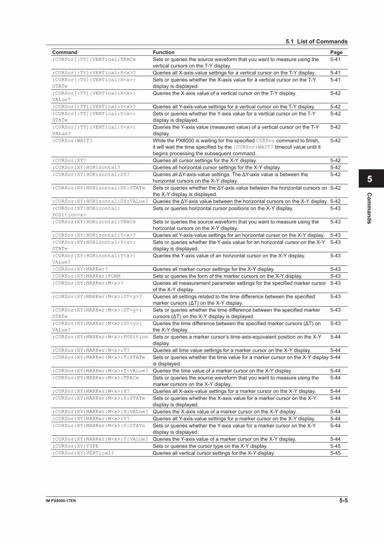
5-5IM PX8000-17EN
Com
mands
1
2
3
4
5
6
App
Index
5.1 List of Commands
Command Function Page:CURSor[:TY]:VERTical:TRACe Sets or queries the source waveform that you want to measure using the
vertical cursors on the T-Y display.5-41
:CURSor[:TY]:VERTical:X<x>? Queries all X-axis-value settings for a vertical cursor on the T-Y display. 5-41:CURSor[:TY]:VERTical:X<x>: STATe
Sets or queries whether the X-axis value for a vertical cursor on the T-Y display is displayed.
5-41
:CURSor[:TY]:VERTical:X<x>: VALue?
Queries the X-axis value of a vertical cursor on the T-Y display. 5-42
:CURSor[:TY]:VERTical:Y<x>? Queries all Y-axis-value settings for a vertical cursor on the T-Y display. 5-42:CURSor[:TY]:VERTical:Y<x>: STATe
Sets or queries whether the Y-axis value for a vertical cursor on the T-Y display is displayed.
5-42
:CURSor[:TY]:VERTical:Y<x>: VALue?
Queries the Y-axis value (measured value) of a vertical cursor on the T-Y display.
5-42
:CURSor:WAIT? While the PX8000 is waiting for the specified CURSor command to finish, it will wait the time specified by the :CURSor:WAIT? timeout value until it begins processing the subsequent command.
5-42
:CURSor:XY? Queries all cursor settings for the X-Y display. 5-42:CURSor:XY:HORizontal? Queries all horizontal cursor settings for the X-Y display. 5-42:CURSor:XY:HORizontal:DY? QueriesallΔY-axis-valuesettings.TheΔY-axisvalueisbetweenthe
horizontal cursors on the X-Y display.5-42
:CURSor:XY:HORizontal:DY:STATe SetsorquerieswhethertheΔY-axisvaluebetweenthehorizontalcursorsonthe X-Y display is displayed.
5-42
:CURSor:XY:HORizontal:DY:VALue? QueriestheΔY-axisvaluebetweenthehorizontalcursorsontheX-Ydisplay. 5-42:CURSor:XY:HORizontal: POSition<x>
Sets or queries horizontal cursor positions on the X-Y display. 5-43
:CURSor:XY:HORizontal:TRACe Sets or queries the source waveform that you want to measure using the horizontal cursors on the X-Y display.
5-43
:CURSor:XY:HORizontal:Y<x>? Queries all Y-axis-value settings for an horizontal cursor on the X-Y display. 5-43:CURSor:XY:HORizontal:Y<x>: STATe
Sets or queries whether the Y-axis value for an horizontal cursor on the X-Y display is displayed.
5-43
:CURSor:XY:HORizontal:Y<x>: VALue?
Queries the Y-axis value of an horizontal cursor on the X-Y display. 5-43
:CURSor:XY:MARKer? Queries all marker cursor settings for the X-Y display. 5-43:CURSor:XY:MARKer:FORM Sets or queries the form of the marker cursors on the X-Y display. 5-43:CURSor:XY:MARKer:M<x>? Queries all measurement parameter settings for the specified marker cursor
of the X-Y display.5-43
:CURSor:XY:MARKer:M<x>:DT<y>? Queries all settings related to the time difference between the specified markercursors(ΔT)ontheX-Ydisplay.
5-43
:CURSor:XY:MARKer:M<x>:DT<y>: STATe
Sets or queries whether the time difference between the specified marker cursors(ΔT)ontheX-Ydisplayisdisplayed.
5-43
:CURSor:XY:MARKer:M<x>:DT<y>: VALue?
Queriesthetimedifferencebetweenthespecifiedmarkercursors(ΔT)onthe X-Y display.
5-43
:CURSor:XY:MARKer:M<x>:POSition Sets or queries a marker cursor’s time-axis-equivalent position on the X-Y display.
5-44
:CURSor:XY:MARKer:M<x>:T? Queries all time value settings for a marker cursor on the X-Y display. 5-44:CURSor:XY:MARKer:M<x>:T:STATe Sets or queries whether the time value for a marker cursor on the X-Y display
is displayed.5-44
:CURSor:XY:MARKer:M<x>:T:VALue? Queries the time value of a marker cursor on the X-Y display. 5-44:CURSor:XY:MARKer:M<x>:TRACe Sets or queries the source waveform that you want to measure using the
marker cursors on the X-Y display.5-44
:CURSor:XY:MARKer:M<x>:X? Queries all X-axis-value settings for a marker cursor on the X-Y display. 5-44:CURSor:XY:MARKer:M<x>:X:STATe Sets or queries whether the X-axis value for a marker cursor on the X-Y
display is displayed.5-44
:CURSor:XY:MARKer:M<x>:X:VALue? Queries the X-axis value of a marker cursor on the X-Y display. 5-44:CURSor:XY:MARKer:M<x>:Y? Queries all Y-axis-value settings for a marker cursor on the X-Y display. 5-44:CURSor:XY:MARKer:M<x>:Y:STATe Sets or queries whether the Y-axis value for a marker cursor on the X-Y
display is displayed.5-44
:CURSor:XY:MARKer:M<x>:Y:VALue? Queries the Y-axis value of a marker cursor on the X-Y display. 5-44:CURSor:XY:TYPE Sets or queries the cursor type on the X-Y display. 5-45:CURSor:XY:VERTical? Queries all vertical cursor settings for the X-Y display. 5-45
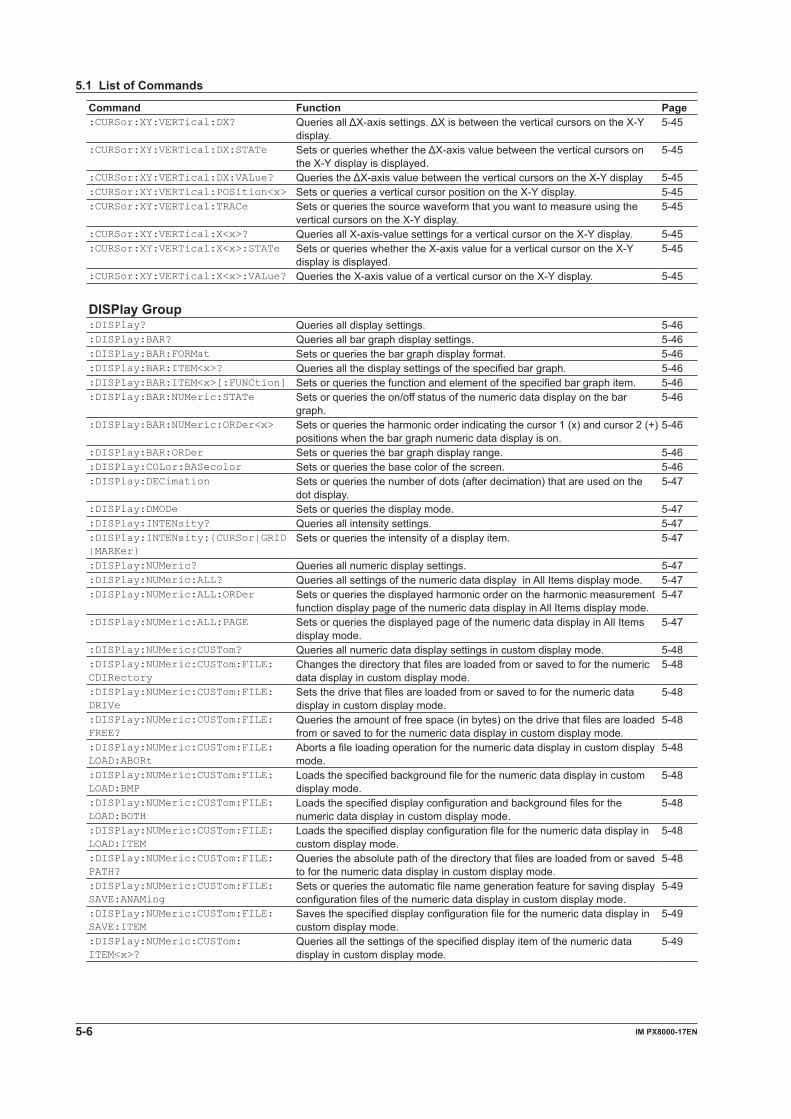
5-6 IM PX8000-17EN
5.1 List of Commands
Command Function Page:CURSor:XY:VERTical:DX? QueriesallΔX-axissettings.ΔXisbetweentheverticalcursorsontheX-Y
display.5-45
:CURSor:XY:VERTical:DX:STATe SetsorquerieswhethertheΔX-axisvaluebetweentheverticalcursorsonthe X-Y display is displayed.
5-45
:CURSor:XY:VERTical:DX:VALue? QueriestheΔX-axisvaluebetweentheverticalcursorsontheX-Ydisplay 5-45:CURSor:XY:VERTical:POSition<x> Sets or queries a vertical cursor position on the X-Y display. 5-45:CURSor:XY:VERTical:TRACe Sets or queries the source waveform that you want to measure using the
vertical cursors on the X-Y display.5-45
:CURSor:XY:VERTical:X<x>? Queries all X-axis-value settings for a vertical cursor on the X-Y display. 5-45:CURSor:XY:VERTical:X<x>:STATe Sets or queries whether the X-axis value for a vertical cursor on the X-Y
display is displayed.5-45
:CURSor:XY:VERTical:X<x>:VALue? Queries the X-axis value of a vertical cursor on the X-Y display. 5-45 DISPlay Group:DISPlay? Queries all display settings. 5-46:DISPlay:BAR? Queries all bar graph display settings. 5-46:DISPlay:BAR:FORMat Sets or queries the bar graph display format. 5-46:DISPlay:BAR:ITEM<x>? Queries all the display settings of the specified bar graph. 5-46:DISPlay:BAR:ITEM<x>[:FUNCtion] Sets or queries the function and element of the specified bar graph item. 5-46:DISPlay:BAR:NUMeric:STATe Sets or queries the on/off status of the numeric data display on the bar
graph.5-46
:DISPlay:BAR:NUMeric:ORDer<x> Sets or queries the harmonic order indicating the cursor 1 (x) and cursor 2 (+) positions when the bar graph numeric data display is on.
5-46
:DISPlay:BAR:ORDer Sets or queries the bar graph display range. 5-46:DISPlay:COLor:BASecolor Sets or queries the base color of the screen. 5-46:DISPlay:DECimation Sets or queries the number of dots (after decimation) that are used on the
dot display.5-47
:DISPlay:DMODe Sets or queries the display mode. 5-47:DISPlay:INTENsity? Queries all intensity settings. 5-47:DISPlay:INTENsity:{CURSor|GRID|MARKer}
Sets or queries the intensity of a display item. 5-47
:DISPlay:NUMeric? Queries all numeric display settings. 5-47:DISPlay:NUMeric:ALL? Queries all settings of the numeric data display in All Items display mode. 5-47:DISPlay:NUMeric:ALL:ORDer Sets or queries the displayed harmonic order on the harmonic measurement
function display page of the numeric data display in All Items display mode.5-47
:DISPlay:NUMeric:ALL:PAGE Sets or queries the displayed page of the numeric data display in All Items display mode.
5-47
:DISPlay:NUMeric:CUSTom? Queries all numeric data display settings in custom display mode. 5-48:DISPlay:NUMeric:CUSTom:FILE: CDIRectory
Changes the directory that files are loaded from or saved to for the numeric data display in custom display mode.
5-48
:DISPlay:NUMeric:CUSTom:FILE: DRIVe
Sets the drive that files are loaded from or saved to for the numeric data display in custom display mode.
5-48
:DISPlay:NUMeric:CUSTom:FILE: FREE?
Queries the amount of free space (in bytes) on the drive that files are loaded from or saved to for the numeric data display in custom display mode.
5-48
:DISPlay:NUMeric:CUSTom:FILE: LOAD:ABORt
Aborts a file loading operation for the numeric data display in custom display mode.
5-48
:DISPlay:NUMeric:CUSTom:FILE: LOAD:BMP
Loads the specified background file for the numeric data display in custom display mode.
5-48
:DISPlay:NUMeric:CUSTom:FILE: LOAD:BOTH
Loads the specified display configuration and background files for the numeric data display in custom display mode.
5-48
:DISPlay:NUMeric:CUSTom:FILE: LOAD:ITEM
Loads the specified display configuration file for the numeric data display in custom display mode.
5-48
:DISPlay:NUMeric:CUSTom:FILE: PATH?
Queries the absolute path of the directory that files are loaded from or saved to for the numeric data display in custom display mode.
5-48
:DISPlay:NUMeric:CUSTom:FILE: SAVE:ANAMing
Sets or queries the automatic file name generation feature for saving display configuration files of the numeric data display in custom display mode.
5-49
:DISPlay:NUMeric:CUSTom:FILE: SAVE:ITEM
Saves the specified display configuration file for the numeric data display in custom display mode.
5-49
:DISPlay:NUMeric:CUSTom: ITEM<x>?
Queries all the settings of the specified display item of the numeric data display in custom display mode.
5-49
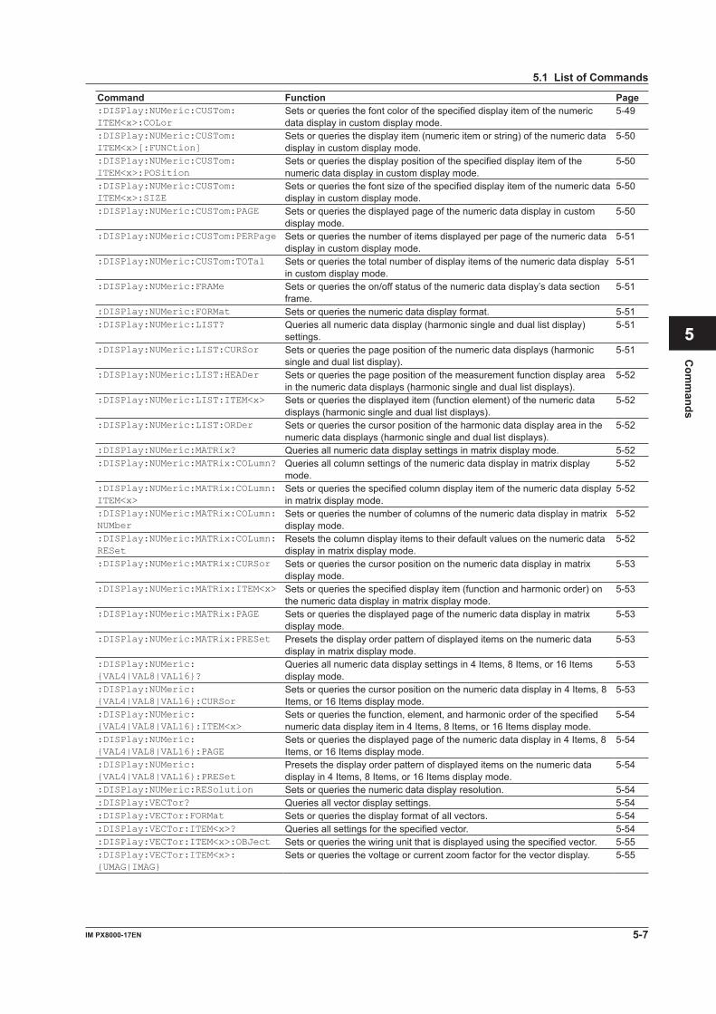
5-7IM PX8000-17EN
Com
mands
1
2
3
4
5
6
App
Index
5.1 List of Commands
Command Function Page:DISPlay:NUMeric:CUSTom: ITEM<x>:COLor
Sets or queries the font color of the specified display item of the numeric data display in custom display mode.
5-49
:DISPlay:NUMeric:CUSTom: ITEM<x>[:FUNCtion]
Sets or queries the display item (numeric item or string) of the numeric data display in custom display mode.
5-50
:DISPlay:NUMeric:CUSTom: ITEM<x>:POSition
Sets or queries the display position of the specified display item of the numeric data display in custom display mode.
5-50
:DISPlay:NUMeric:CUSTom: ITEM<x>:SIZE
Sets or queries the font size of the specified display item of the numeric data display in custom display mode.
5-50
:DISPlay:NUMeric:CUSTom:PAGE Sets or queries the displayed page of the numeric data display in custom display mode.
5-50
:DISPlay:NUMeric:CUSTom:PERPage Sets or queries the number of items displayed per page of the numeric data display in custom display mode.
5-51
:DISPlay:NUMeric:CUSTom:TOTal Sets or queries the total number of display items of the numeric data display in custom display mode.
5-51
:DISPlay:NUMeric:FRAMe Sets or queries the on/off status of the numeric data display’s data section frame.
5-51
:DISPlay:NUMeric:FORMat Sets or queries the numeric data display format. 5-51:DISPlay:NUMeric:LIST? Queries all numeric data display (harmonic single and dual list display)
settings. 5-51
:DISPlay:NUMeric:LIST:CURSor Sets or queries the page position of the numeric data displays (harmonic single and dual list display).
5-51
:DISPlay:NUMeric:LIST:HEADer Sets or queries the page position of the measurement function display area in the numeric data displays (harmonic single and dual list displays).
5-52
:DISPlay:NUMeric:LIST:ITEM<x> Sets or queries the displayed item (function element) of the numeric data displays (harmonic single and dual list displays).
5-52
:DISPlay:NUMeric:LIST:ORDer Sets or queries the cursor position of the harmonic data display area in the numeric data displays (harmonic single and dual list displays).
5-52
:DISPlay:NUMeric:MATRix? Queries all numeric data display settings in matrix display mode. 5-52:DISPlay:NUMeric:MATRix:COLumn? Queries all column settings of the numeric data display in matrix display
mode.5-52
:DISPlay:NUMeric:MATRix:COLumn:ITEM<x>
Sets or queries the specified column display item of the numeric data display in matrix display mode.
5-52
:DISPlay:NUMeric:MATRix:COLumn:NUMber
Sets or queries the number of columns of the numeric data display in matrix display mode.
5-52
:DISPlay:NUMeric:MATRix:COLumn:RESet
Resets the column display items to their default values on the numeric data display in matrix display mode.
5-52
:DISPlay:NUMeric:MATRix:CURSor Sets or queries the cursor position on the numeric data display in matrix display mode.
5-53
:DISPlay:NUMeric:MATRix:ITEM<x> Sets or queries the specified display item (function and harmonic order) on the numeric data display in matrix display mode.
5-53
:DISPlay:NUMeric:MATRix:PAGE Sets or queries the displayed page of the numeric data display in matrix display mode.
5-53
:DISPlay:NUMeric:MATRix:PRESet Presets the display order pattern of displayed items on the numeric data display in matrix display mode.
5-53
:DISPlay:NUMeric: {VAL4|VAL8|VAL16}?
Queries all numeric data display settings in 4 Items, 8 Items, or 16 Items display mode.
5-53
:DISPlay:NUMeric: {VAL4|VAL8|VAL16}:CURSor
Sets or queries the cursor position on the numeric data display in 4 Items, 8 Items, or 16 Items display mode.
5-53
:DISPlay:NUMeric: {VAL4|VAL8|VAL16}:ITEM<x>
Sets or queries the function, element, and harmonic order of the specified numeric data display item in 4 Items, 8 Items, or 16 Items display mode.
5-54
:DISPlay:NUMeric: {VAL4|VAL8|VAL16}:PAGE
Sets or queries the displayed page of the numeric data display in 4 Items, 8 Items, or 16 Items display mode.
5-54
:DISPlay:NUMeric: {VAL4|VAL8|VAL16}:PRESet
Presets the display order pattern of displayed items on the numeric data display in 4 Items, 8 Items, or 16 Items display mode.
5-54
:DISPlay:NUMeric:RESolution Sets or queries the numeric data display resolution. 5-54:DISPlay:VECTor? Queries all vector display settings. 5-54:DISPlay:VECTor:FORMat Sets or queries the display format of all vectors. 5-54:DISPlay:VECTor:ITEM<x>? Queries all settings for the specified vector. 5-54:DISPlay:VECTor:ITEM<x>:OBJect Sets or queries the wiring unit that is displayed using the specified vector. 5-55:DISPlay:VECTor:ITEM<x>: {UMAG|IMAG}
Sets or queries the voltage or current zoom factor for the vector display. 5-55
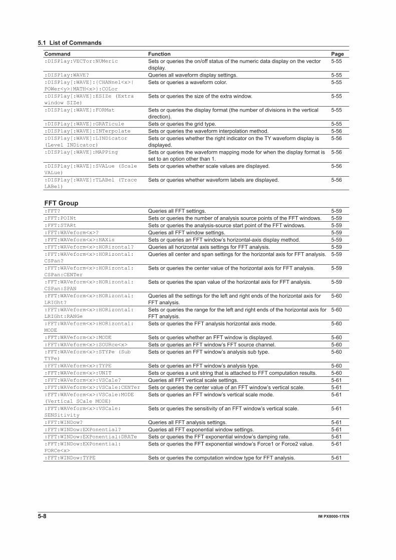
5-8 IM PX8000-17EN
5.1 List of Commands
Command Function Page:DISPlay:VECTor:NUMeric Sets or queries the on/off status of the numeric data display on the vector
display.5-55
:DISPlay:WAVE? Queries all waveform display settings. 5-55:DISPlay[:WAVE]:{CHANnel<x>| POWer<y>|MATH<x>}:COLor
Sets or queries a waveform color. 5-55
:DISPlay[:WAVE]:ESIZe (Extra window SIZe)
Sets or queries the size of the extra window. 5-55
:DISPlay[:WAVE]:FORMat Sets or queries the display format (the number of divisions in the vertical direction).
5-55
:DISPlay[:WAVE]:GRATicule Sets or queries the grid type. 5-55:DISPlay[:WAVE]:INTerpolate Sets or queries the waveform interpolation method. 5-56:DISPlay[:WAVE]:LINDicator (Level INDicator)
Sets or queries whether the right indicator on the TY waveform display is displayed.
5-56
:DISPlay[:WAVE]:MAPPing Sets or queries the waveform mapping mode for when the display format is set to an option other than 1.
5-56
:DISPlay[:WAVE]:SVALue (Scale VALue)
Sets or queries whether scale values are displayed. 5-56
:DISPlay[:WAVE]:TLABel (Trace LABel)
Sets or queries whether waveform labels are displayed. 5-56
FFT Group:FFT? Queries all FFT settings. 5-59:FFT:POINt Sets or queries the number of analysis source points of the FFT windows. 5-59:FFT:STARt Sets or queries the analysis-source start point of the FFT windows. 5-59:FFT:WAVeform<x>? Queries all FFT window settings. 5-59:FFT:WAVeform<x>:HAXis Sets or queries an FFT window’s horizontal-axis display method. 5-59:FFT:WAVeform<x>:HORizontal? Queries all horizontal axis settings for FFT analysis. 5-59:FFT:WAVeform<x>:HORizontal: CSPan?
Queries all center and span settings for the horizontal axis for FFT analysis. 5-59
:FFT:WAVeform<x>:HORizontal: CSPan:CENTer
Sets or queries the center value of the horizontal axis for FFT analysis. 5-59
:FFT:WAVeform<x>:HORizontal: CSPan:SPAN
Sets or queries the span value of the horizontal axis for FFT analysis. 5-59
:FFT:WAVeform<x>:HORizontal: LRIGht?
Queries all the settings for the left and right ends of the horizontal axis for FFT analysis.
5-60
:FFT:WAVeform<x>:HORizontal: LRIGht:RANGe
Sets or queries the range for the left and right ends of the horizontal axis for FFT analysis.
5-60
:FFT:WAVeform<x>:HORizontal: MODE
Sets or queries the FFT analysis horizontal axis mode. 5-60
:FFT:WAVeform<x>:MODE Sets or queries whether an FFT window is displayed. 5-60:FFT:WAVeform<x>:SOURce<x> Sets or queries an FFT window’s FFT source channel. 5-60:FFT:WAVeform<x>:STYPe (Sub TYPe)
Sets or queries an FFT window’s analysis sub type. 5-60
:FFT:WAVeform<x>:TYPE Sets or queries an FFT window’s analysis type. 5-60:FFT:WAVeform<x>:UNIT Sets or queries a unit string that is attached to FFT computation results. 5-60:FFT:WAVeform<x>:VSCale? Queries all FFT vertical scale settings. 5-61:FFT:WAVeform<x>:VSCale:CENTer Sets or queries the center value of an FFT window’s vertical scale. 5-61:FFT:WAVeform<x>:VSCale:MODE (Vertical SCale MODE)
Sets or queries an FFT window’s vertical scale mode. 5-61
:FFT:WAVeform<x>:VSCale: SENSitivity
Sets or queries the sensitivity of an FFT window’s vertical scale. 5-61
:FFT:WINDow? Queries all FFT analysis settings. 5-61:FFT:WINDow:EXPonential? Queries all FFT exponential window settings. 5-61:FFT:WINDow:EXPonential:DRATe Sets or queries the FFT exponential window’s damping rate. 5-61:FFT:WINDow:EXPonential: FORCe<x>
Sets or queries the FFT exponential window’s Force1 or Force2 value. 5-61
:FFT:WINDow:TYPE Sets or queries the computation window type for FFT analysis. 5-61
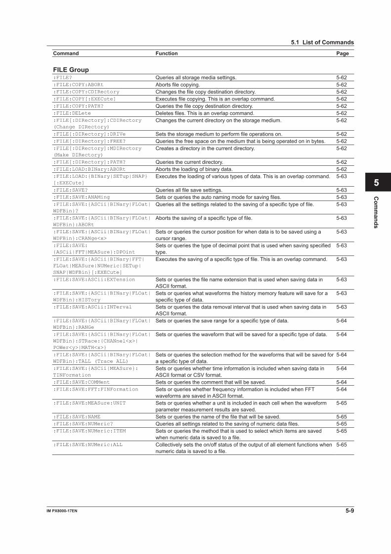
5-9IM PX8000-17EN
Com
mands
1
2
3
4
5
6
App
Index
5.1 List of Commands
Command Function Page FILE Group:FILE? Queries all storage media settings. 5-62:FILE:COPY:ABORt Aborts file copying. 5-62:FILE:COPY:CDIRectory Changes the file copy destination directory. 5-62:FILE:COPY[:EXECute] Executes file copying. This is an overlap command. 5-62:FILE:COPY:PATH? Queries the file copy destination directory. 5-62:FILE:DELete Deletes files. This is an overlap command. 5-62:FILE[:DIRectory]:CDIRectory (Change DIRectory)
Changes the current directory on the storage medium. 5-62
:FILE[:DIRectory]:DRIVe Sets the storage medium to perform file operations on. 5-62:FILE[:DIRectory]:FREE? Queries the free space on the medium that is being operated on in bytes. 5-62:FILE[:DIRectory]:MDIRectory (Make DIRectory)
Creates a directory in the current directory. 5-62
:FILE[:DIRectory]:PATH? Queries the current directory. 5-62:FILE:LOAD:BINary:ABORt Aborts the loading of binary data. 5-62:FILE:LOAD:{BINary|SETup|SNAP}[:EXECute]
Executes the loading of various types of data. This is an overlap command. 5-63
:FILE:SAVE? Queries all file save settings. 5-63:FILE:SAVE:ANAMing Sets or queries the auto naming mode for saving files. 5-63:FILE:SAVE:{ASCii|BINary|FLOat| WDFBin}?
Queries all the settings related to the saving of a specific type of file. 5-63
:FILE:SAVE:{ASCii|BINary|FLOat| WDFBin}:ABORt
Aborts the saving of a specific type of file. 5-63
:FILE:SAVE:{ASCii|BINary|FLOat| WDFBin}:CRANge<x>
Sets or queries the cursor position for when data is to be saved using a cursor range.
5-63
:FILE:SAVE: {ASCii|FFT|MEASure}:DPOint
Sets or queries the type of decimal point that is used when saving specified type.
5-63
:FILE:SAVE:{ASCii|BINary|FFT| FLOat|MEASure|NUMeric|SETup| SNAP|WDFBin}[:EXECute]
Executes the saving of a specific type of file. This is an overlap command. 5-63
:FILE:SAVE:ASCii:EXTension Sets or queries the file name extension that is used when saving data in ASCII format.
5-63
:FILE:SAVE:{ASCii|BINary|FLOat| WDFBin}:HISTory
Sets or queries what waveforms the history memory feature will save for a specific type of data.
5-63
:FILE:SAVE:ASCii:INTerval Sets or queries the data removal interval that is used when saving data in ASCII format.
5-63
:FILE:SAVE:{ASCii|BINary|FLOat| WDFBin}:RANGe
Sets or queries the save range for a specific type of data. 5-64
:FILE:SAVE:{ASCii|BINary|FLOat| WDFBin}:STRace:{CHANnel<x>| POWer<y>|MATH<x>}
Sets or queries the waveform that will be saved for a specific type of data. 5-64
:FILE:SAVE:{ASCii|BINary|FLOat| WDFBin}:TALL (Trace ALL)
Sets or queries the selection method for the waveforms that will be saved for a specific type of data.
5-64
:FILE:SAVE:{ASCii|MEASure}: TINFormation
Sets or queries whether time information is included when saving data in ASCII format or CSV format.
5-64
:FILE:SAVE:COMMent Sets or queries the comment that will be saved. 5-64:FILE:SAVE:FFT:FINFormation Sets or queries whether frequency information is included when FFT
waveforms are saved in ASCII format.5-64
:FILE:SAVE:MEASure:UNIT Sets or queries whether a unit is included in each cell when the waveform parameter measurement results are saved.
5-65
:FILE:SAVE:NAME Sets or queries the name of the file that will be saved. 5-65:FILE:SAVE:NUMeric? Queries all settings related to the saving of numeric data files. 5-65:FILE:SAVE:NUMeric:ITEM Sets or queries the method that is used to select which items are saved
when numeric data is saved to a file.5-65
:FILE:SAVE:NUMeric:ALL Collectively sets the on/off status of the output of all element functions when numeric data is saved to a file.
5-65

5-10 IM PX8000-17EN
5.1 List of Commands
Command Function Page:FILE:SAVE:NUMeric:{ELEMent<x>|SIGMA|SIGMB}
Sets or queries the on/off status of the output of the specified element or wiringunitΣAorΣBwhennumericdataissavedtoafile.
5-65
:FILE:SAVE:NUMeric:<Function> Sets or queries the on/off status of the specified function’s output when numeric data is saved to a file.
5-65
:FILE:SAVE:NUMeric:PRESet Presets the output on/off pattern of the element functions to be used when numeric data is saved to a file.
5-65
GONogo Group:GONogo? Queries all GO/NO-GO determination settings. 5-66:GONogo:ACONdition Sets or queries the GO/NO-GO determination-action condition. 5-66:GONogo:ACTion? Queries all settings for the action that is performed when the condition is met
and the settings for the condition itself.5-66
:GONogo:ACTion:BUZZer Sets or queries whether a beep is sounded when the condition is met. 5-66:GONogo:ACTion:HCOPy (HardCOPy) Sets or queries whether a screen capture is printed from the built-in printer
when the condition is met.5-66
:GONogo:ACTion:IMAGe? Queries all settings for the screen capture that is saved when the condition is met.
5-66
:GONogo:ACTion:IMAGe:CDIRectory Sets the current directory where the screen capture is saved to when the condition is met.
5-66
:GONogo:ACTion:IMAGe:DRIVe Sets or queries the medium that the screen capture is saved to when the condition is met.
5-66
:GONogo:ACTion:IMAGe[:MODE] Sets or queries whether a screen capture is saved when the condition is met. 5-66:GONogo:ACTion:IMAGe:PATH? Queries the path on the storage medium that a screen capture is saved to
when the condition is met.5-67
:GONogo:ACTion:SAVE? Queries all settings related to the storage medium that waveform data is saved to when the condition is met.
5-67
:GONogo:ACTion:SAVE:CDIRectory Sets the current directory on the storage medium where waveform data is saved to when the condition is met.
5-67
:GONogo:ACTion:SAVE:DRIVe Sets or queries the storage medium that waveform data is saved to when the condition is met.
5-67
:GONogo:ACTion:SAVE[:MODE] Sets or queries whether waveforms are saved to the storage medium when the condition is met.
5-67
:GONogo:ACTion:SAVE:PATH? Queries the path on the storage medium that waveform data is saved to when the condition is met.
5-67
:GONogo:ACTion:SAVE:TYPE Sets or queries the file format that waveforms are saved as on the storage medium when the condition is met.
5-67
:GONogo:COUNt? Queries the number of GO/NO-GO determinations that were performed. 5-67:GONogo:LOGic Sets or queries the GO/NO-GO determination logic. 5-67:GONogo:MODE Sets or queries the GO/NO-GO determination mode. 5-67:GONogo:NGCount? Queries the GO/NO-GO determination NO-GO count. 5-67:GONogo:PARameter? Queries all parameter determination settings. 5-68:GONogo:PARameter:ITEM<x>? Queries all settings for the specified waveform parameter for parameter
determination.5-68
:GONogo:PARameter:ITEM<x>: CAUSe?
Queries whether the specified waveform parameter for parameter determination is the cause of a NO-GO judgment.
5-68
:GONogo:PARameter:ITEM<x>:MODE Sets or queries the specified waveform parameter’s reference condition for parameter determination.
5-68
:GONogo:PARameter:ITEM<x>:TRACe Sets or queries the specified waveform parameter’s source waveform for parameter determination.
5-68
:GONogo:PARameter:ITEM<x>:TYPE? Queries, for parameter determination, the specified waveform parameter’s measurement item and upper and lower limits.
5-68
:GONogo:PARameter:ITEM<x>: TYPE:<Parameter>
Sets or queries the upper and lower limits of the measurement item for the specified waveform parameter.
5-68
:GONogo:PARameter:ITEM<x>: VALue?
Queries the measured value of the specified waveform parameter. 5-68
:GONogo:REMote Sets or queries the remote mode of GO/NO-GO determination. 5-68:GONogo:SEQuence Sets or queries the action mode of GO/NO-GO determination. 5-68:GONogo:TRANge Sets or queries the determination range of GO/NO-GO determination. 5-69:GONogo:WAIT? Waits for the completion of GO/NO-GO determination by using a timeout
value.5-69
:GONogo:ZONE? Queries all waveform zone determination settings. 5-69
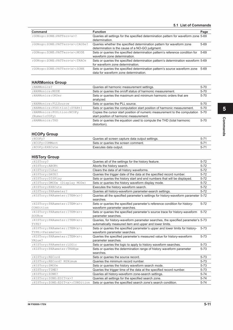
5-11IM PX8000-17EN
Com
mands
1
2
3
4
5
6
App
Index
5.1 List of Commands
Command Function Page:GONogo:ZONE:PATTern<x>? Queries all settings for the specified determination pattern for waveform zone
determination.5-69
:GONogo:ZONE:PATTern<x>:CAUSe? Queries whether the specified determination pattern for waveform zone determination is the cause of a NO-GO judgment.
5-69
:GONogo:ZONE:PATTern<x>:MODE Sets or queries the specified determination pattern’s reference condition for waveform zone determination.
5-69
:GONogo:ZONE:PATTern<x>:TRACe Sets or queries the specified determination pattern’s determination waveform for waveform zone determination.
5-69
:GONogo:ZONE:PATTern<x>:ZONE Sets or queries the specified determination pattern’s source waveform zone data for waveform zone determination.
5-69
HARMonics Group:HARMonics? Queries all harmonic measurement settings. 5-70:HARMonics:MODE Sets or queries the on/off status of harmonic measurement. 5-70:HARMonics:ORDer Sets or queries the maximum and minimum harmonic orders that are
analyzed.5-70
:HARMonics:PLLSource Sets or queries the PLL source. 5-70:HARMonics:POSition[:STARt] Sets or queries the computation start position of harmonic measurement. 5-70:HARMonics:POSition:NCOPy (NumericCOPy)
Copies the cursor start position of numeric measurement to the computation start position of harmonic measurement.
5-70
:HARMonics:THD Sets or queries the equation used to compute the THD (total harmonic distortion).
5-70
HCOPy Group:HCOPy? Queries all screen capture data output settings. 5-71:HCOPy:COMMent Sets or queries the screen comment. 5-71:HCOPy:EXECute Executes data output. 5-71 HISTory Group:HISTory? Queries all of the settings for the history feature. 5-72:HISTory:ABORt Aborts the history search. 5-72:HISTory:CLEar Clears the data of all history waveforms. 5-72:HISTory:DATE? Queries the trigger date of the data at the specified record number. 5-72:HISTory:DISPlay Sets or queries the history start and end numbers that will be displayed. 5-72:HISTory:DMODe (Display MODe) Sets or queries the history waveform display mode. 5-72:HISTory:EXECute Executes the history waveform search. 5-72:HISTory:PARameter? Queries all history-waveform parameter-search settings. 5-72:HISTory:PARameter:ITEM<x>? Queries all the specified parameter’s settings for history-waveform parameter
searches.5-72
:HISTory:PARameter:ITEM<x>: CONDition
Sets or queries the specified parameter’s reference condition for history-waveform parameter searches.
5-72
:HISTory:PARameter:ITEM<x>: SOURce
Sets or queries the specified parameter’s source trace for history-waveform parameter searches.
5-72
:HISTory:PARameter:ITEM<x>: TYPE?
Queries, for history-waveform parameter searches, the specified parameter’s automatically measured item and upper and lower limits.
5-73
:HISTory:PARameter:ITEM<x>: TYPE:<Parameter>
Sets or queries the specified parameter’s upper and lower limits for history-waveform parameter searches.
5-73
:HISTory:PARameter:ITEM<x>: VALue?
Queries the specified parameter’s measured value for history-waveform parameter searches.
5-73
:HISTory:PARameter:LOGic Sets or queries the logic to apply to history waveform searches. 5-73:HISTory:PARameter:TRANge Sets or queries the determination range of history waveform parameter
searches.5-73
:HISTory:RECord Sets or queries the source record. 5-73:HISTory:RECord? MINimum Queries the minimum record number. 5-73:HISTory:SMODe Sets or queries the history waveform search mode. 5-73:HISTory:TIME? Queries the trigger time of the data at the specified record number. 5-73:HISTory:ZONE? Queries all history-waveform zone-search settings. 5-74:HISTory:ZONE:EDIT<x>? Queries all settings for the specified search zone. 5-74:HISTory:ZONE:EDIT<x>:CONDition Sets or queries the specified search zone’s search condition. 5-74
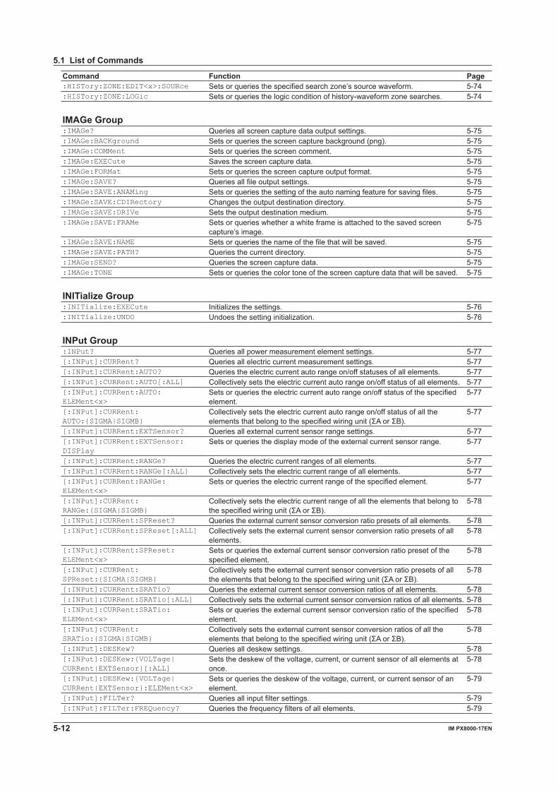
5-12 IM PX8000-17EN
5.1 List of Commands
Command Function Page:HISTory:ZONE:EDIT<x>:SOURce Sets or queries the specified search zone’s source waveform. 5-74:HISTory:ZONE:LOGic Sets or queries the logic condition of history-waveform zone searches. 5-74 IMAGe Group:IMAGe? Queries all screen capture data output settings. 5-75:IMAGe:BACKground Sets or queries the screen capture background (png). 5-75:IMAGe:COMMent Sets or queries the screen comment. 5-75:IMAGe:EXECute Saves the screen capture data. 5-75:IMAGe:FORMat Sets or queries the screen capture output format. 5-75:IMAGe:SAVE? Queries all file output settings. 5-75:IMAGe:SAVE:ANAMing Sets or queries the setting of the auto naming feature for saving files. 5-75:IMAGe:SAVE:CDIRectory Changes the output destination directory. 5-75:IMAGe:SAVE:DRIVe Sets the output destination medium. 5-75:IMAGe:SAVE:FRAMe Sets or queries whether a white frame is attached to the saved screen
capture’s image.5-75
:IMAGe:SAVE:NAME Sets or queries the name of the file that will be saved. 5-75:IMAGe:SAVE:PATH? Queries the current directory. 5-75:IMAGe:SEND? Queries the screen capture data. 5-75:IMAGe:TONE Sets or queries the color tone of the screen capture data that will be saved. 5-75 INITialize Group:INITialize:EXECute Initializes the settings. 5-76:INITialize:UNDO Undoes the setting initialization. 5-76 INPut Group:INPut? Queries all power measurement element settings. 5-77[:INPut]:CURRent? Queries all electric current measurement settings. 5-77[:INPut]:CURRent:AUTO? Queries the electric current auto range on/off statuses of all elements. 5-77[:INPut]:CURRent:AUTO[:ALL] Collectively sets the electric current auto range on/off status of all elements. 5-77[:INPut]:CURRent:AUTO: ELEMent<x>
Sets or queries the electric current auto range on/off status of the specified element.
5-77
[:INPut]:CURRent: AUTO:{SIGMA|SIGMB}
Collectively sets the electric current auto range on/off status of all the elementsthatbelongtothespecifiedwiringunit(ΣAorΣB).
5-77
[:INPut]:CURRent:EXTSensor? Queries all external current sensor range settings. 5-77[:INPut]:CURRent:EXTSensor: DISPlay
Sets or queries the display mode of the external current sensor range. 5-77
[:INPut]:CURRent:RANGe? Queries the electric current ranges of all elements. 5-77[:INPut]:CURRent:RANGe[:ALL] Collectively sets the electric current range of all elements. 5-77[:INPut]:CURRent:RANGe: ELEMent<x>
Sets or queries the electric current range of the specified element. 5-77
[:INPut]:CURRent: RANGe:{SIGMA|SIGMB}
Collectively sets the electric current range of all the elements that belong to thespecifiedwiringunit(ΣAorΣB).
5-78
[:INPut]:CURRent:SPReset? Queries the external current sensor conversion ratio presets of all elements. 5-78[:INPut]:CURRent:SPReset[:ALL] Collectively sets the external current sensor conversion ratio presets of all
elements.5-78
[:INPut]:CURRent:SPReset: ELEMent<x>
Sets or queries the external current sensor conversion ratio preset of the specified element.
5-78
[:INPut]:CURRent: SPReset:{SIGMA|SIGMB}
Collectively sets the external current sensor conversion ratio presets of all theelementsthatbelongtothespecifiedwiringunit(ΣAorΣB).
5-78
[:INPut]:CURRent:SRATio? Queries the external current sensor conversion ratios of all elements. 5-78[:INPut]:CURRent:SRATio[:ALL] Collectively sets the external current sensor conversion ratios of all elements. 5-78[:INPut]:CURRent:SRATio: ELEMent<x>
Sets or queries the external current sensor conversion ratio of the specified element.
5-78
[:INPut]:CURRent: SRATio:{SIGMA|SIGMB}
Collectively sets the external current sensor conversion ratios of all the elementsthatbelongtothespecifiedwiringunit(ΣAorΣB).
5-78
[:INPut]:DESKew? Queries all deskew settings. 5-78[:INPut]:DESKew:{VOLTage| CURRent|EXTSensor}[:ALL]
Sets the deskew of the voltage, current, or current sensor of all elements at once.
5-78
[:INPut]:DESKew:{VOLTage| CURRent|EXTSensor}:ELEMent<x>
Sets or queries the deskew of the voltage, current, or current sensor of an element.
5-79
[:INPut]:FILTer? Queries all input filter settings. 5-79[:INPut]:FILTer:FREQuency? Queries the frequency filters of all elements. 5-79
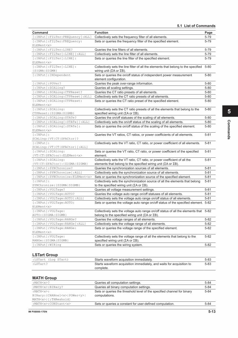
5-13IM PX8000-17EN
Com
mands
1
2
3
4
5
6
App
Index
5.1 List of Commands
Command Function Page[:INPut]:FILTer:FREQuency[:ALL] Collectively sets the frequency filter of all elements. 5-79[:INPut]:FILTer:FREQuency: ELEMent<x>
Sets or queries the frequency filter of the specified element. 5-79
[:INPut]:FILTer:LINE? Queries the line filters of all elements. 5-79[:INPut]:FILTer[:LINE][:ALL] Collectively sets the line filter of all elements. 5-79[:INPut]:FILTer[:LINE]: ELEMent<x>
Sets or queries the line filter of the specified element. 5-79
[:INPut]:FILTer[:LINE]: {SIGMA|SIGMB}
Collectively sets the line filter of all the elements that belong to the specified wiringunit(ΣAorΣB).
5-80
[:INPut]:INDependent Sets or queries the on/off status of independent power measurement element configuration.
5-80
[:INPut]:POVer? Queries the peak over-range information. 5-80[:INPut]:SCALing? Queries all scaling settings. 5-80[:INPut]:SCALing:CTPReset? Queries the CT ratio presets of all elements. 5-80[:INPut]:SCALing:CTPReset[:ALL] Collectively sets the CT ratio presets of all elements. 5-80[:INPut]:SCALing:CTPReset: ELEMent<x>
Sets or queries the CT ratio preset of the specified element. 5-80
[:INPut]:SCALing: CTPReset:{SIGMA|SIGMB}
Collectively sets the CT ratio presets of all the elements that belong to the specifiedwiringunit(ΣAorΣB).
5-80
[:INPut]:SCALing:STATe? Queries the on/off statuses of the scaling of all elements. 5-80[:INPut]:SCALing[:STATe][:ALL] Collectively sets the on/off status of the scaling of all elements. 5-80[:INPut]:SCALing[:STATe]: ELEMent<x>
Sets or queries the on/off status of the scaling of the specified element. 5-80
[:INPut]: SCALing:{VT|CT|SFACtor}?
Queries the VT ratios, CT ratios, or power coefficients of all elements. 5-81
[:INPut]: SCALing:{VT|CT|SFACtor}[:ALL]
Collectively sets the VT ratio, CT ratio, or power coefficient of all elements. 5-81
[:INPut]:SCALing: {VT|CT|SFACtor}:ELEMent<x>
Sets or queries the VT ratio, CT ratio, or power coefficient of the specified element.
5-81
[:INPut]:SCALing: {VT|CT|SFACtor}:{SIGMA|SIGMB}
Collectively sets the VT ratio, CT ratio, or power coefficient of all the elementsthatbelongtothespecifiedwiringunit(ΣAorΣB).
5-81
[:INPut]:SYNChronize? Queries the synchronization sources of all elements. 5-81[:INPut]:SYNChronize[:ALL] Collectively sets the synchronization source of all elements. 5-81[:INPut]:SYNChronize:ELEMent<x> Sets or queries the synchronization source of the specified element. 5-81[:INPut]: SYNChronize:{SIGMA|SIGMB}
Collectively sets the synchronization source of all the elements that belong tothespecifiedwiringunit(ΣAorΣB).
5-81
[:INPut]:VOLTage? Queries all voltage measurement settings. 5-81[:INPut]:VOLTage:AUTO? Queries the voltage auto range on/off statuses of all elements. 5-81[:INPut]:VOLTage:AUTO[:ALL] Collectively sets the voltage auto range on/off status of all elements. 5-81[:INPut]:VOLTage:AUTO: ELEMent<x>
Sets or queries the voltage auto range on/off status of the specified element. 5-82
[:INPut]:VOLTage: AUTO:{SIGMA|SIGMB}
Collectively sets the voltage auto range on/off status of all the elements that belongtothespecifiedwiringunit(ΣAorΣB).
5-82
[:INPut]:VOLTage:RANGe? Queries the voltage ranges of all elements. 5-82[:INPut]:VOLTage:RANGe[:ALL] Collectively sets the voltage range of all elements. 5-82[:INPut]:VOLTage:RANGe: ELEMent<x>
Sets or queries the voltage range of the specified element. 5-82
[:INPut]:VOLTage: RANGe:{SIGMA|SIGMB}
Collectively sets the voltage range of all the elements that belong to the specifiedwiringunit(ΣAorΣB).
5-82
[:INPut]:WIRing Sets or queries the wiring system. 5-82 LSTart Group:LSTart (Log STart) Starts waveform acquisition immediately. 5-83:LSTart? Starts waveform acquisition immediately, and waits for acquisition to
complete.5-83
MATH Group:MATH<x>? Queries all computation settings. 5-84:MATH<x>:BINary? Queries all binary computation settings. 5-84:MATH<x>: BINary:{CHANnel<x>|POWer<y>| MATH<x>}[:THReshold]
Sets or queries the threshold level of the specified channel for binary computations.
5-84
:MATH<x>:CONStant<x> Sets or queries a constant for user-defined computation. 5-84
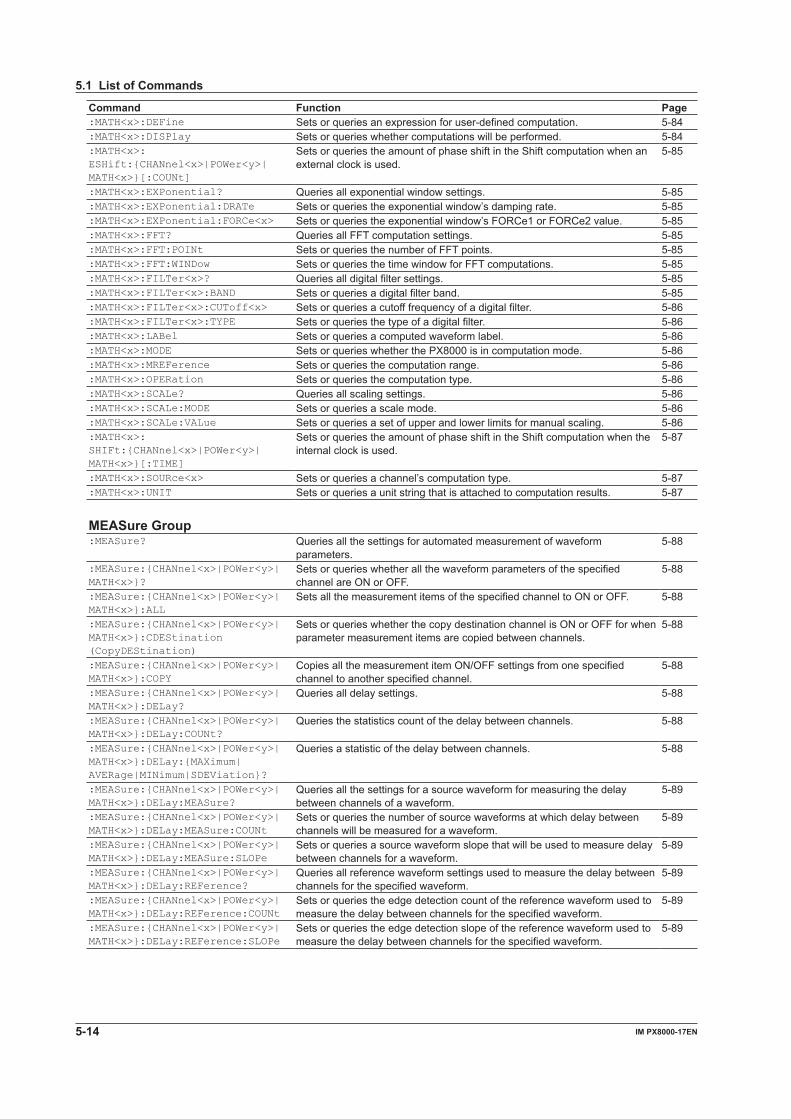
5-14 IM PX8000-17EN
5.1 List of Commands
Command Function Page:MATH<x>:DEFine Sets or queries an expression for user-defined computation. 5-84:MATH<x>:DISPlay Sets or queries whether computations will be performed. 5-84:MATH<x>: ESHift:{CHANnel<x>|POWer<y>| MATH<x>}[:COUNt]
Sets or queries the amount of phase shift in the Shift computation when an external clock is used.
5-85
:MATH<x>:EXPonential? Queries all exponential window settings. 5-85:MATH<x>:EXPonential:DRATe Sets or queries the exponential window’s damping rate. 5-85:MATH<x>:EXPonential:FORCe<x> Sets or queries the exponential window’s FORCe1 or FORCe2 value. 5-85:MATH<x>:FFT? Queries all FFT computation settings. 5-85:MATH<x>:FFT:POINt Sets or queries the number of FFT points. 5-85:MATH<x>:FFT:WINDow Sets or queries the time window for FFT computations. 5-85:MATH<x>:FILTer<x>? Queries all digital filter settings. 5-85:MATH<x>:FILTer<x>:BAND Sets or queries a digital filter band. 5-85:MATH<x>:FILTer<x>:CUToff<x> Sets or queries a cutoff frequency of a digital filter. 5-86:MATH<x>:FILTer<x>:TYPE Sets or queries the type of a digital filter. 5-86:MATH<x>:LABel Sets or queries a computed waveform label. 5-86:MATH<x>:MODE Sets or queries whether the PX8000 is in computation mode. 5-86:MATH<x>:MREFerence Sets or queries the computation range. 5-86:MATH<x>:OPERation Sets or queries the computation type. 5-86:MATH<x>:SCALe? Queries all scaling settings. 5-86:MATH<x>:SCALe:MODE Sets or queries a scale mode. 5-86:MATH<x>:SCALe:VALue Sets or queries a set of upper and lower limits for manual scaling. 5-86:MATH<x>: SHIFt:{CHANnel<x>|POWer<y>| MATH<x>}[:TIME]
Sets or queries the amount of phase shift in the Shift computation when the internal clock is used.
5-87
:MATH<x>:SOURce<x> Sets or queries a channel’s computation type. 5-87:MATH<x>:UNIT Sets or queries a unit string that is attached to computation results. 5-87 MEASure Group:MEASure? Queries all the settings for automated measurement of waveform
parameters.5-88
:MEASure:{CHANnel<x>|POWer<y>| MATH<x>}?
Sets or queries whether all the waveform parameters of the specified channel are ON or OFF.
5-88
:MEASure:{CHANnel<x>|POWer<y>| MATH<x>}:ALL
Sets all the measurement items of the specified channel to ON or OFF. 5-88
:MEASure:{CHANnel<x>|POWer<y>| MATH<x>}:CDEStination (CopyDEStination)
Sets or queries whether the copy destination channel is ON or OFF for when parameter measurement items are copied between channels.
5-88
:MEASure:{CHANnel<x>|POWer<y>| MATH<x>}:COPY
Copies all the measurement item ON/OFF settings from one specified channel to another specified channel.
5-88
:MEASure:{CHANnel<x>|POWer<y>| MATH<x>}:DELay?
Queries all delay settings. 5-88
:MEASure:{CHANnel<x>|POWer<y>| MATH<x>}:DELay:COUNt?
Queries the statistics count of the delay between channels. 5-88
:MEASure:{CHANnel<x>|POWer<y>| MATH<x>}:DELay:{MAXimum| AVERage|MINimum|SDEViation}?
Queries a statistic of the delay between channels. 5-88
:MEASure:{CHANnel<x>|POWer<y>| MATH<x>}:DELay:MEASure?
Queries all the settings for a source waveform for measuring the delay between channels of a waveform.
5-89
:MEASure:{CHANnel<x>|POWer<y>| MATH<x>}:DELay:MEASure:COUNt
Sets or queries the number of source waveforms at which delay between channels will be measured for a waveform.
5-89
:MEASure:{CHANnel<x>|POWer<y>| MATH<x>}:DELay:MEASure:SLOPe
Sets or queries a source waveform slope that will be used to measure delay between channels for a waveform.
5-89
:MEASure:{CHANnel<x>|POWer<y>| MATH<x>}:DELay:REFerence?
Queries all reference waveform settings used to measure the delay between channels for the specified waveform.
5-89
:MEASure:{CHANnel<x>|POWer<y>| MATH<x>}:DELay:REFerence:COUNt
Sets or queries the edge detection count of the reference waveform used to measure the delay between channels for the specified waveform.
5-89
:MEASure:{CHANnel<x>|POWer<y>| MATH<x>}:DELay:REFerence:SLOPe
Sets or queries the edge detection slope of the reference waveform used to measure the delay between channels for the specified waveform.
5-89
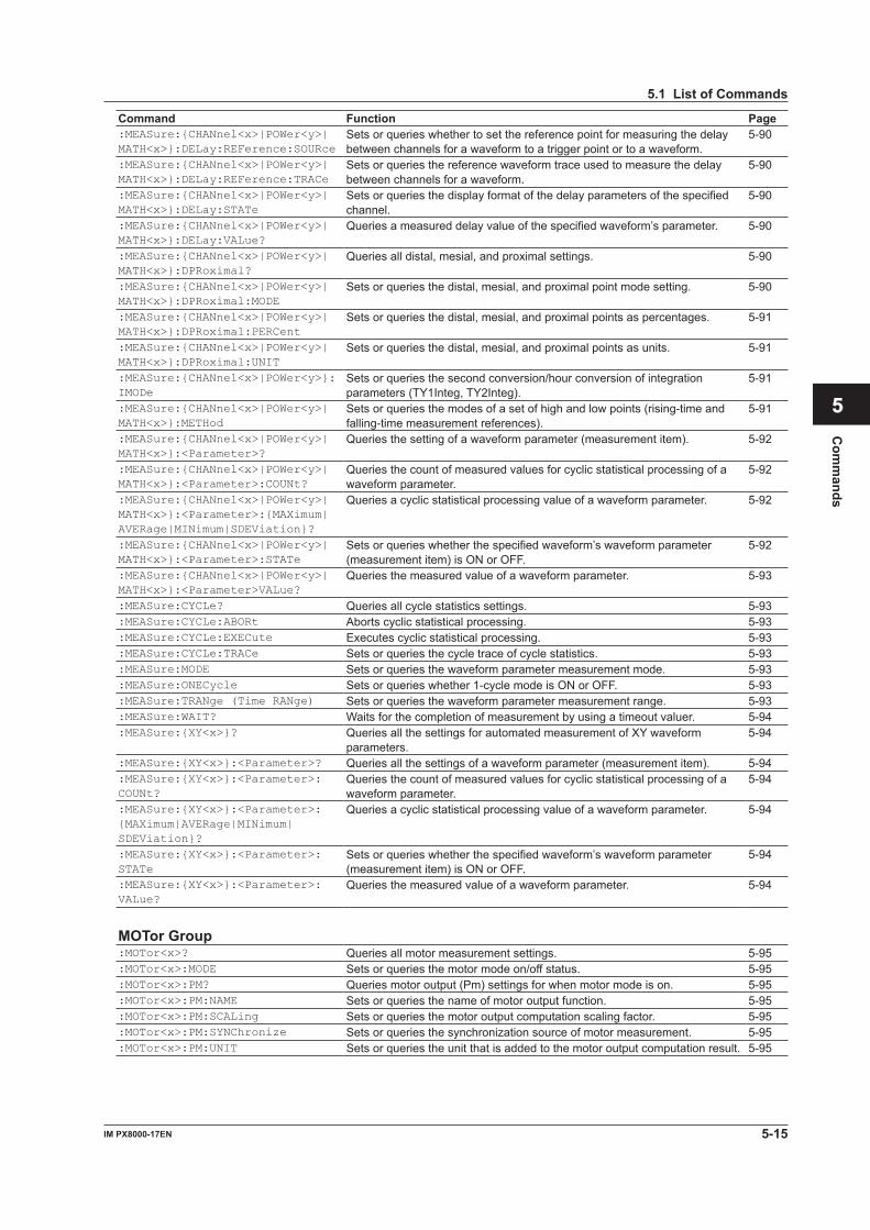
5-15IM PX8000-17EN
Com
mands
1
2
3
4
5
6
App
Index
5.1 List of Commands
Command Function Page:MEASure:{CHANnel<x>|POWer<y>| MATH<x>}:DELay:REFerence:SOURce
Sets or queries whether to set the reference point for measuring the delay between channels for a waveform to a trigger point or to a waveform.
5-90
:MEASure:{CHANnel<x>|POWer<y>| MATH<x>}:DELay:REFerence:TRACe
Sets or queries the reference waveform trace used to measure the delay between channels for a waveform.
5-90
:MEASure:{CHANnel<x>|POWer<y>| MATH<x>}:DELay:STATe
Sets or queries the display format of the delay parameters of the specified channel.
5-90
:MEASure:{CHANnel<x>|POWer<y>| MATH<x>}:DELay:VALue?
Queries a measured delay value of the specified waveform’s parameter. 5-90
:MEASure:{CHANnel<x>|POWer<y>| MATH<x>}:DPRoximal?
Queries all distal, mesial, and proximal settings. 5-90
:MEASure:{CHANnel<x>|POWer<y>| MATH<x>}:DPRoximal:MODE
Sets or queries the distal, mesial, and proximal point mode setting. 5-90
:MEASure:{CHANnel<x>|POWer<y>| MATH<x>}:DPRoximal:PERCent
Sets or queries the distal, mesial, and proximal points as percentages. 5-91
:MEASure:{CHANnel<x>|POWer<y>| MATH<x>}:DPRoximal:UNIT
Sets or queries the distal, mesial, and proximal points as units. 5-91
:MEASure:{CHANnel<x>|POWer<y>}:IMODe
Sets or queries the second conversion/hour conversion of integration parameters (TY1Integ, TY2Integ).
5-91
:MEASure:{CHANnel<x>|POWer<y>| MATH<x>}:METHod
Sets or queries the modes of a set of high and low points (rising-time and falling-time measurement references).
5-91
:MEASure:{CHANnel<x>|POWer<y>| MATH<x>}:<Parameter>?
Queries the setting of a waveform parameter (measurement item). 5-92
:MEASure:{CHANnel<x>|POWer<y>| MATH<x>}:<Parameter>:COUNt?
Queries the count of measured values for cyclic statistical processing of a waveform parameter.
5-92
:MEASure:{CHANnel<x>|POWer<y>| MATH<x>}:<Parameter>:{MAXimum| AVERage|MINimum|SDEViation}?
Queries a cyclic statistical processing value of a waveform parameter. 5-92
:MEASure:{CHANnel<x>|POWer<y>| MATH<x>}:<Parameter>:STATe
Sets or queries whether the specified waveform’s waveform parameter (measurement item) is ON or OFF.
5-92
:MEASure:{CHANnel<x>|POWer<y>| MATH<x>}:<Parameter>VALue?
Queries the measured value of a waveform parameter. 5-93
:MEASure:CYCLe? Queries all cycle statistics settings. 5-93:MEASure:CYCLe:ABORt Aborts cyclic statistical processing. 5-93:MEASure:CYCLe:EXECute Executes cyclic statistical processing. 5-93:MEASure:CYCLe:TRACe Sets or queries the cycle trace of cycle statistics. 5-93:MEASure:MODE Sets or queries the waveform parameter measurement mode. 5-93:MEASure:ONECycle Sets or queries whether 1-cycle mode is ON or OFF. 5-93:MEASure:TRANge (Time RANge) Sets or queries the waveform parameter measurement range. 5-93:MEASure:WAIT? Waits for the completion of measurement by using a timeout valuer. 5-94:MEASure:{XY<x>}? Queries all the settings for automated measurement of XY waveform
parameters.5-94
:MEASure:{XY<x>}:<Parameter>? Queries all the settings of a waveform parameter (measurement item). 5-94:MEASure:{XY<x>}:<Parameter>: COUNt?
Queries the count of measured values for cyclic statistical processing of a waveform parameter.
5-94
:MEASure:{XY<x>}:<Parameter>: {MAXimum|AVERage|MINimum| SDEViation}?
Queries a cyclic statistical processing value of a waveform parameter. 5-94
:MEASure:{XY<x>}:<Parameter>: STATe
Sets or queries whether the specified waveform’s waveform parameter (measurement item) is ON or OFF.
5-94
:MEASure:{XY<x>}:<Parameter>: VALue?
Queries the measured value of a waveform parameter. 5-94
MOTor Group:MOTor<x>? Queries all motor measurement settings. 5-95:MOTor<x>:MODE Sets or queries the motor mode on/off status. 5-95:MOTor<x>:PM? Queries motor output (Pm) settings for when motor mode is on. 5-95:MOTor<x>:PM:NAME Sets or queries the name of motor output function. 5-95:MOTor<x>:PM:SCALing Sets or queries the motor output computation scaling factor. 5-95:MOTor<x>:PM:SYNChronize Sets or queries the synchronization source of motor measurement. 5-95:MOTor<x>:PM:UNIT Sets or queries the unit that is added to the motor output computation result. 5-95
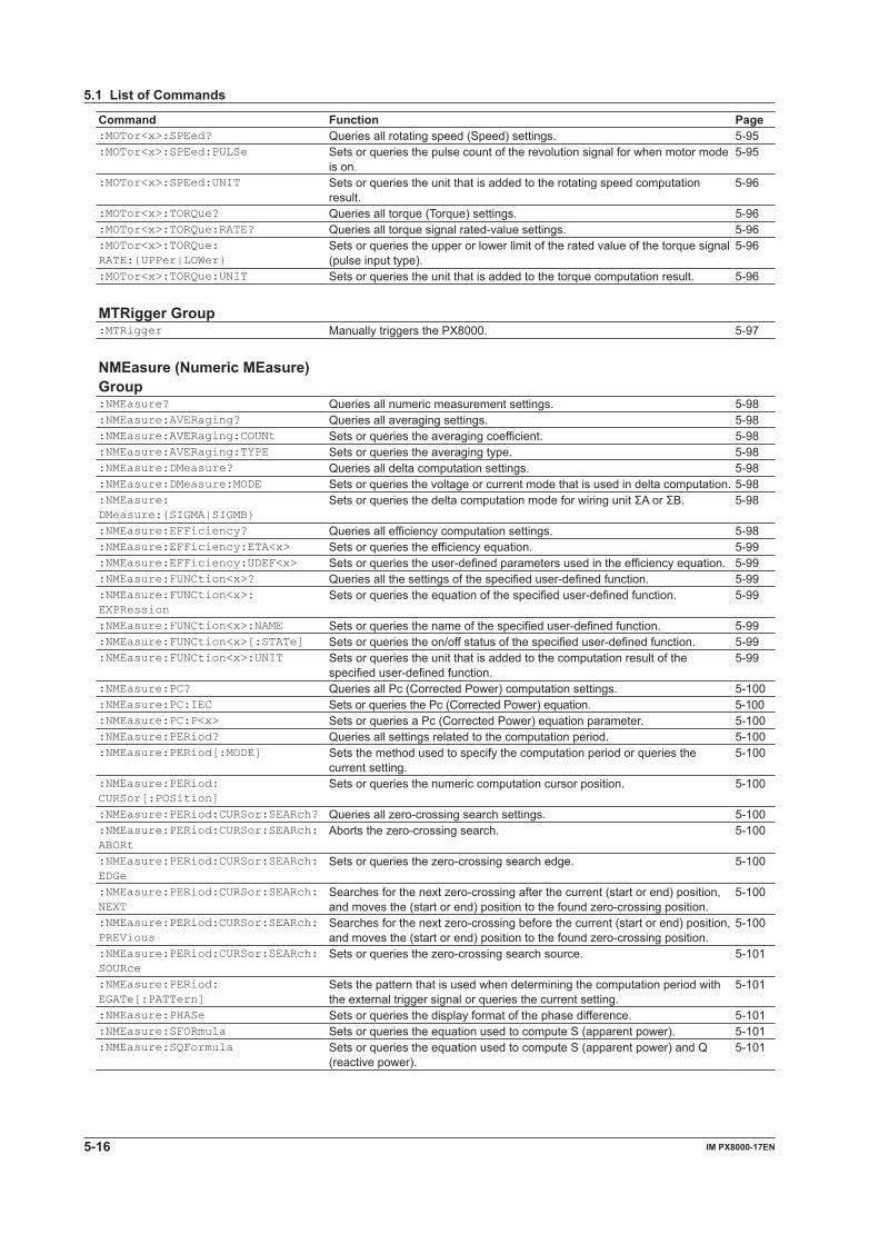
5-16 IM PX8000-17EN
5.1 List of Commands
Command Function Page:MOTor<x>:SPEed? Queries all rotating speed (Speed) settings. 5-95:MOTor<x>:SPEed:PULSe Sets or queries the pulse count of the revolution signal for when motor mode
is on.5-95
:MOTor<x>:SPEed:UNIT Sets or queries the unit that is added to the rotating speed computation result.
5-96
:MOTor<x>:TORQue? Queries all torque (Torque) settings. 5-96:MOTor<x>:TORQue:RATE? Queries all torque signal rated-value settings. 5-96:MOTor<x>:TORQue: RATE:{UPPer|LOWer}
Sets or queries the upper or lower limit of the rated value of the torque signal (pulse input type).
5-96
:MOTor<x>:TORQue:UNIT Sets or queries the unit that is added to the torque computation result. 5-96 MTRigger Group:MTRigger Manually triggers the PX8000. 5-97 NMEasure (Numeric MEasure) Group:NMEasure? Queries all numeric measurement settings. 5-98:NMEasure:AVERaging? Queries all averaging settings. 5-98:NMEasure:AVERaging:COUNt Sets or queries the averaging coefficient. 5-98:NMEasure:AVERaging:TYPE Sets or queries the averaging type. 5-98:NMEasure:DMeasure? Queries all delta computation settings. 5-98:NMEasure:DMeasure:MODE Sets or queries the voltage or current mode that is used in delta computation. 5-98:NMEasure: DMeasure:{SIGMA|SIGMB}
SetsorqueriesthedeltacomputationmodeforwiringunitΣAorΣB. 5-98
:NMEasure:EFFiciency? Queries all efficiency computation settings. 5-98:NMEasure:EFFiciency:ETA<x> Sets or queries the efficiency equation. 5-99:NMEasure:EFFiciency:UDEF<x> Sets or queries the user-defined parameters used in the efficiency equation. 5-99:NMEasure:FUNCtion<x>? Queries all the settings of the specified user-defined function. 5-99:NMEasure:FUNCtion<x>: EXPRession
Sets or queries the equation of the specified user-defined function. 5-99
:NMEasure:FUNCtion<x>:NAME Sets or queries the name of the specified user-defined function. 5-99:NMEasure:FUNCtion<x>[:STATe] Sets or queries the on/off status of the specified user-defined function. 5-99:NMEasure:FUNCtion<x>:UNIT Sets or queries the unit that is added to the computation result of the
specified user-defined function.5-99
:NMEasure:PC? Queries all Pc (Corrected Power) computation settings. 5-100:NMEasure:PC:IEC Sets or queries the Pc (Corrected Power) equation. 5-100:NMEasure:PC:P<x> Sets or queries a Pc (Corrected Power) equation parameter. 5-100:NMEasure:PERiod? Queries all settings related to the computation period. 5-100:NMEasure:PERiod[:MODE] Sets the method used to specify the computation period or queries the
current setting.5-100
:NMEasure:PERiod: CURSor[:POSition]
Sets or queries the numeric computation cursor position. 5-100
:NMEasure:PERiod:CURSor:SEARch? Queries all zero-crossing search settings. 5-100:NMEasure:PERiod:CURSor:SEARch:ABORt
Aborts the zero-crossing search. 5-100
:NMEasure:PERiod:CURSor:SEARch:EDGe
Sets or queries the zero-crossing search edge. 5-100
:NMEasure:PERiod:CURSor:SEARch:NEXT
Searches for the next zero-crossing after the current (start or end) position, and moves the (start or end) position to the found zero-crossing position.
5-100
:NMEasure:PERiod:CURSor:SEARch:PREVious
Searches for the next zero-crossing before the current (start or end) position, and moves the (start or end) position to the found zero-crossing position.
5-100
:NMEasure:PERiod:CURSor:SEARch:SOURce
Sets or queries the zero-crossing search source. 5-101
:NMEasure:PERiod: EGATe[:PATTern]
Sets the pattern that is used when determining the computation period with the external trigger signal or queries the current setting.
5-101
:NMEasure:PHASe Sets or queries the display format of the phase difference. 5-101:NMEasure:SFORmula Sets or queries the equation used to compute S (apparent power). 5-101:NMEasure:SQFormula Sets or queries the equation used to compute S (apparent power) and Q
(reactive power).5-101
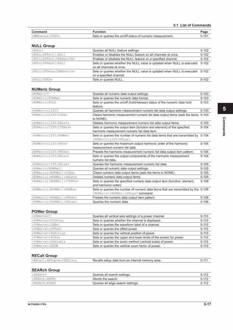
5-17IM PX8000-17EN
Com
mands
1
2
3
4
5
6
App
Index
5.1 List of Commands
Command Function Page:NMEasure:STATe Sets or queries the on/off status of numeric measurement. 5-101 NULL Group:NULL? Queries all NULL feature settings. 5-102:NULL:AFFect[:ALL] Enables or disables the NULL feature on all channels at once. 5-102:NULL:AFFect:CHANnel<x> Enables or disables the NULL feature on a specified channel. 5-102:NULL:UPDate[:ALL] Sets or queries whether the NULL value is updated when NULL is executed
on all channels at once.5-102
:NULL:UPDate:CHANnel<x> Sets or queries whether the NULL value is updated when NULL is executed on a specified channel.
5-102
:NULL:STATe Sets or queries NULL. 5-102 NUMeric Group:NUMeric? Queries all numeric data output settings. 5-103:NUMeric:FORMat Sets or queries the numeric data format. 5-103:NUMeric:HOLD Sets or queries the on/off (hold/release) status of the numeric data hold
feature.5-103
:NUMeric:LIST? Queries all harmonic measurement numeric list data output settings. 5-103:NUMeric:LIST:CLEar Clears harmonic measurement numeric list data output items (sets the items
to NONE).5-103
:NUMeric:LIST:DELete Deletes harmonic measurement numeric list data output items. 5-103:NUMeric:LIST:ITEM<x> Sets or queries the output item (function and element) of the specified
harmonic measurement numeric list data item.5-104
:NUMeric:LIST:NUMber Sets or queries the number of numeric list data items that are transmitted by :NUMeric:LIST:VALue?.
5-104
:NUMeric:LIST:ORDer Sets or queries the maximum output harmonic order of the harmonic measurement numeric list data.
5-104
:NUMeric:LIST:PRESet Presets the harmonic measurement numeric list data output item pattern. 5-104:NUMeric:LIST:SELect Sets or queries the output components of the harmonic measurement
numeric list data.5-104
:NUMeric:LIST:VALue? Queries the harmonic measurement numeric list data. 5-105:NUMeric:NORMal? Queries all numeric data output settings. 5-105:NUMeric[:NORMal]:CLEar Clears numeric data output items (sets the items to NONE). 5-105:NUMeric[:NORMal]:DELete Deletes numeric data output items. 5-105:NUMeric[:NORMal]:ITEM<x> Sets or queries the specified numeric data output item (function, element,
and harmonic order).5-106
:NUMeric[:NORMal]:NUMber Sets or queries the number of numeric data items that are transmitted by the :NUMeric[:NORMal]:VALue? command.
5-106
:NUMeric[:NORMal]:PRESet Presets the numeric data output item pattern. 5-106:NUMeric[:NORMal]:VALue? Queries the numeric data. 5-106 POWer Group:POWer<x>? Queries all vertical axis settings of a power channel. 5-110:POWer<x>:DISPlay Sets or queries whether the channel is displayed. 5-110:POWer<x>:LABel Sets or queries the waveform label of a channel. 5-110:POWer<x>:OFFSet Sets or queries the offset power. 5-110:POWer<x>:POSition Sets or queries the vertical position of power. 5-110:POWer<x>:SCALe Sets or queries the upper and lower limits of the screen for power. 5-110:POWer<x>:VARiable Sets or queries the zoom method (vertical scale) of power. 5-110:POWer<x>:ZOOM Sets or queries the vertical zoom factor of power. 5-110 RECall Group:RECall:SETup<x>:EXECute Recalls setup data from an internal memory area. 5-111 SEARch Group:SEARch? Queries all search settings. 5-112:SEARch:ABORt Aborts the search. 5-112:SEARch:EDGE? Queries all edge search settings. 5-112
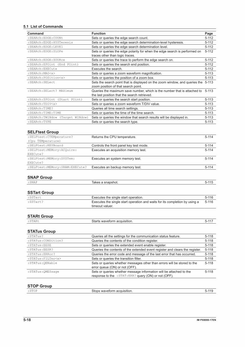
5-18 IM PX8000-17EN
5.1 List of Commands
Command Function Page:SEARch:EDGE:COUNt Sets or queries the edge search count. 5-112:SEARch:EDGE:HYSTeresis Sets or queries the edge search determination-level hysteresis. 5-112:SEARch:EDGE:LEVEl Sets or queries the edge search determination level. 5-112:SEARch:EDGE:SLOPe Sets or queries the edge polarity for when the edge search is performed on
traces other than logic traces.5-112
:SEARch:EDGE:SOURce Sets or queries the trace to perform the edge search on. 5-112:SEARch:EPOint (End POint) Sets or queries the search end position. 5-112:SEARch:EXECute Executes the search. 5-112:SEARch:MAG<x> Sets or queries a zoom waveform magnification. 5-113:SEARch:POSition<x> Sets or queries the position of a zoom box. 5-113:SEARch:SELect Sets the search point that is displayed on the zoom window, and queries the
zoom position of that search point.5-113
:SEARch:SELect? MAXimum Queries the maximum save number, which is the number that is attached to the last position that the search retrieved.
5-113
:SEARch:SPOint (Start POint) Sets or queries the search start position. 5-113:SEARch:TDIV<x> Sets or queries a zoom waveform T/DIV value. 5-113:SEARch:TIME? Queries all time search settings. 5-113:SEARch:TIME:TIME Sets or queries the time of the time search. 5-113:SEARch:TWINdow (Target WINdow) Sets or queries the window that search results will be displayed in. 5-113:SEARch:TYPE Sets or queries the search type. 5-113 SELFtest Group:SELFtest:CTEMperature? (Cpu TEMperature)
Returns the CPU temperature. 5-114
:SELFtest:KEYBoard Controls the front panel key test mode. 5-114:SELFtest:MEMory:ACQuire: EXECute?
Executes an acquisition memory test. 5-114
:SELFtest:MEMory:SYSTem: EXECute?
Executes an system memory test. 5-114
:SELFtest:MEMory:SRAM:EXECute? Executes an backup memory test. 5-114 SNAP Group:SNAP Takes a snapshot. 5-115 SSTart Group:SSTart Executes the single start operation. 5-116:SSTart? Executes the single start operation and waits for its completion by using a
timeout valuer.5-116
STARt Group:STARt Starts waveform acquisition. 5-117 STATus Group:STATus? Queries all the settings for the communication status feature. 5-118:STATus:CONDition? Queries the contents of the condition register. 5-118:STATus:EESE Sets or queries the extended event enable register. 5-118:STATus:EESR? Queries the contents of the extended event register and clears the register. 5-118:STATus:ERRor? Queries the error code and message of the last error that has occurred. 5-118:STATus:FILTer<x> Sets or queries the transition filter. 5-118:STATus:QENable Sets or queries whether messages other than errors will be stored to the
error queue (ON) or not (OFF).5-118
:STATus:QMESsage Sets or queries whether message information will be attached to the response to the :STAT:ERR? query (ON) or not (OFF).
5-118
STOP Group:STOP Stops waveform acquisition. 5-119
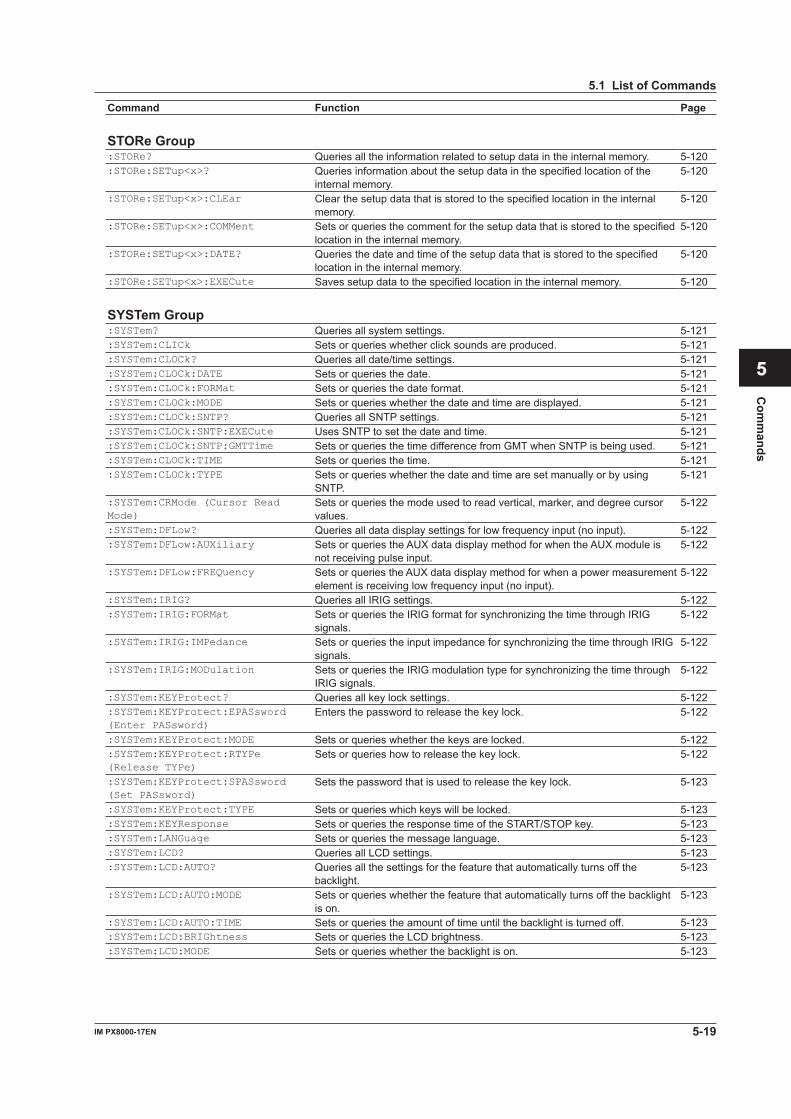
5-19IM PX8000-17EN
Com
mands
1
2
3
4
5
6
App
Index
5.1 List of Commands
Command Function Page STORe Group:STORe? Queries all the information related to setup data in the internal memory. 5-120:STORe:SETup<x>? Queries information about the setup data in the specified location of the
internal memory.5-120
:STORe:SETup<x>:CLEar Clear the setup data that is stored to the specified location in the internal memory.
5-120
:STORe:SETup<x>:COMMent Sets or queries the comment for the setup data that is stored to the specified location in the internal memory.
5-120
:STORe:SETup<x>:DATE? Queries the date and time of the setup data that is stored to the specified location in the internal memory.
5-120
:STORe:SETup<x>:EXECute Saves setup data to the specified location in the internal memory. 5-120 SYSTem Group:SYSTem? Queries all system settings. 5-121:SYSTem:CLICk Sets or queries whether click sounds are produced. 5-121:SYSTem:CLOCk? Queries all date/time settings. 5-121:SYSTem:CLOCk:DATE Sets or queries the date. 5-121:SYSTem:CLOCk:FORMat Sets or queries the date format. 5-121:SYSTem:CLOCk:MODE Sets or queries whether the date and time are displayed. 5-121:SYSTem:CLOCk:SNTP? Queries all SNTP settings. 5-121:SYSTem:CLOCk:SNTP:EXECute Uses SNTP to set the date and time. 5-121:SYSTem:CLOCk:SNTP:GMTTime Sets or queries the time difference from GMT when SNTP is being used. 5-121:SYSTem:CLOCk:TIME Sets or queries the time. 5-121:SYSTem:CLOCk:TYPE Sets or queries whether the date and time are set manually or by using
SNTP.5-121
:SYSTem:CRMode (Cursor Read Mode)
Sets or queries the mode used to read vertical, marker, and degree cursor values.
5-122
:SYSTem:DFLow? Queries all data display settings for low frequency input (no input). 5-122:SYSTem:DFLow:AUXiliary Sets or queries the AUX data display method for when the AUX module is
not receiving pulse input.5-122
:SYSTem:DFLow:FREQuency Sets or queries the AUX data display method for when a power measurement element is receiving low frequency input (no input).
5-122
:SYSTem:IRIG? Queries all IRIG settings. 5-122:SYSTem:IRIG:FORMat Sets or queries the IRIG format for synchronizing the time through IRIG
signals.5-122
:SYSTem:IRIG:IMPedance Sets or queries the input impedance for synchronizing the time through IRIG signals.
5-122
:SYSTem:IRIG:MODulation Sets or queries the IRIG modulation type for synchronizing the time through IRIG signals.
5-122
:SYSTem:KEYProtect? Queries all key lock settings. 5-122:SYSTem:KEYProtect:EPASsword (Enter PASsword)
Enters the password to release the key lock. 5-122
:SYSTem:KEYProtect:MODE Sets or queries whether the keys are locked. 5-122:SYSTem:KEYProtect:RTYPe (Release TYPe)
Sets or queries how to release the key lock. 5-122
:SYSTem:KEYProtect:SPASsword (Set PASsword)
Sets the password that is used to release the key lock. 5-123
:SYSTem:KEYProtect:TYPE Sets or queries which keys will be locked. 5-123:SYSTem:KEYResponse Sets or queries the response time of the START/STOP key. 5-123:SYSTem:LANGuage Sets or queries the message language. 5-123:SYSTem:LCD? Queries all LCD settings. 5-123:SYSTem:LCD:AUTO? Queries all the settings for the feature that automatically turns off the
backlight.5-123
:SYSTem:LCD:AUTO:MODE Sets or queries whether the feature that automatically turns off the backlight is on.
5-123
:SYSTem:LCD:AUTO:TIME Sets or queries the amount of time until the backlight is turned off. 5-123:SYSTem:LCD:BRIGhtness Sets or queries the LCD brightness. 5-123:SYSTem:LCD:MODE Sets or queries whether the backlight is on. 5-123
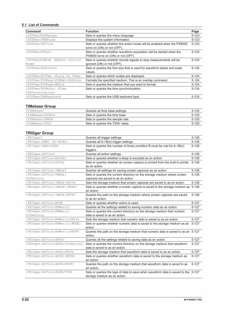
5-20 IM PX8000-17EN
5.1 List of Commands
Command Function Page:SYSTem:MLANguage Sets or queries the menu language. 5-123:SYSTem:OVERview Displays the system information. 5-123:SYSTem:PACTion Sets or queries whether the action mode will be enabled when the PX8000
turns on (ON) or not (OFF).5-123
:SYSTem:PSTart Sets or queries whether waveform acquisition will be started when the PX8000 turns on (ON) or not (OFF).
5-124
:SYSTem:RCMode (Remote Control Mode)
Sets or queries whether remote signals to stop measurements will be ignored (ON) or not (OFF).
5-124
:SYSTem:SCALefont Sets or queries the font size that is used for waveform labels and scale values.
5-124
:SYSTem:SOITem (Scale On ITem) Sets or queries which scales are displayed. 5-124:SYSTem:STORage:FORMat:EXECute Formats the specified medium. This is an overlap command. 5-124:SYSTem:STORage:MEDia Sets or queries the medium that you want to format. 5-124:SYSTem:TSYNchro (Time SYNchronization)
Sets or queries the time synchronization. 5-124
:SYSTem:USBKeyboard Sets or queries the USB keyboard type. 5-124 TIMebase Group:TIMebase? Queries all time base settings. 5-125:TIMebase:SOURce Sets or queries the time base. 5-125:TIMebase:SRATe Sets or queries the sample rate. 5-125:TIMebase:TDIV Sets or queries the T/DIV value. 5-125 TRIGger Group:TRIGger? Queries all trigger settings. 5-126:TRIGger:ABN? (A->B(N)) Queries all A->B(n) trigger settings. 5-126:TRIGger:ABN:COUNt Sets or queries the number of times condition B must be met for A->B(n)
triggers.5-126
:TRIGger:ACTion? Queries all action settings. 5-126:TRIGger:ACTion:BUZZer Sets or queries whether a beep is sounded as an action. 5-126:TRIGger:ACTion:HCOPy Sets or queries whether an screen capture is printed from the built-in printer
as an action.5-126
:TRIGger:ACTion:IMAGe? Queries all settings for saving screen captures as an action. 5-126:TRIGger:ACTion:IMAGe: CDIRectory
Sets or queries the current directory on the storage medium where screen captures are saved to as an action.
5-126
:TRIGger:ACTion:IMAGe:DRIVe Sets the storage medium that screen captures are saved to as an action. 5-126:TRIGger:ACTion:IMAGe[:MODE] Sets or queries whether a screen capture is saved to the storage medium as
an action.5-126
:TRIGger:ACTion:IMAGe:PATH? Queries the path on the storage medium where screen captures are saved to as an action.
5-126
:TRIGger:ACTion:MODE Sets or queries whether action is used. 5-127:TRIGger:ACTion:NUMeric? Queries all the settings related to saving numeric data as an action. 5-127:TRIGger:ACTion:NUMeric: CDIRectory
Sets or queries the current directory on the storage medium that numeric data is saved to as an action.
5-127
:TRIGger:ACTion:NUMeric:DRIVe Sets the storage medium that numeric data is saved to as an action. 5-127:TRIGger:ACTion:NUMeric[:MODE] Sets or queries whether numeric data is saved to the storage medium as an
action.5-127
:TRIGger:ACTion:NUMeric:PATH? Queries the path on the storage medium that numeric data is saved to as an action.
5-127
:TRIGger:ACTion:SAVE? Queries all the settings related to saving data as an action. 5-127:TRIGger:ACTion:SAVE:CDIRectory Sets or queries the current directory on the storage medium that waveform
data is saved to as an action.5-127
:TRIGger:ACTion:SAVE:DRIVe Sets the storage medium that waveform data is saved to as an action. 5-127:TRIGger:ACTion:SAVE[:MODE] Sets or queries whether waveform data is saved to the storage medium as
an action.5-127
:TRIGger:ACTion:SAVE:PATH? Queries the path on the storage medium that waveform data is saved to as an action.
5-127
:TRIGger:ACTion:SAVE:TYPE Sets or queries the type of data to save when waveform data is saved to the storage medium as an action.
5-127
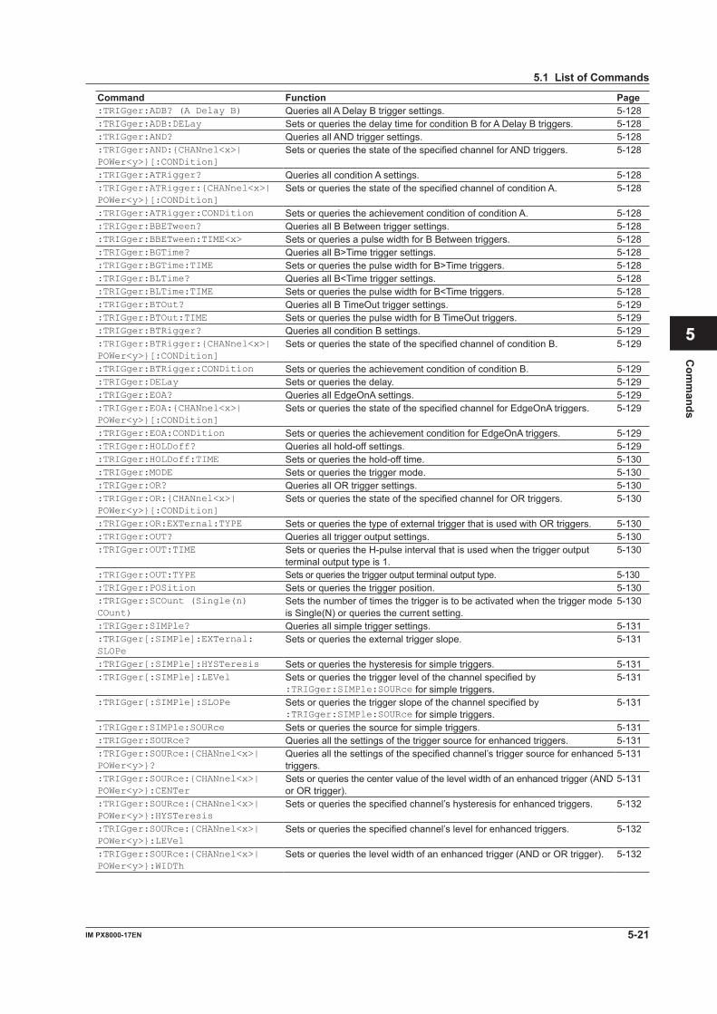
5-21IM PX8000-17EN
Com
mands
1
2
3
4
5
6
App
Index
5.1 List of Commands
Command Function Page:TRIGger:ADB? (A Delay B) Queries all A Delay B trigger settings. 5-128:TRIGger:ADB:DELay Sets or queries the delay time for condition B for A Delay B triggers. 5-128:TRIGger:AND? Queries all AND trigger settings. 5-128:TRIGger:AND:{CHANnel<x>| POWer<y>}[:CONDition]
Sets or queries the state of the specified channel for AND triggers. 5-128
:TRIGger:ATRigger? Queries all condition A settings. 5-128:TRIGger:ATRigger:{CHANnel<x>| POWer<y>}[:CONDition]
Sets or queries the state of the specified channel of condition A. 5-128
:TRIGger:ATRigger:CONDition Sets or queries the achievement condition of condition A. 5-128:TRIGger:BBETween? Queries all B Between trigger settings. 5-128:TRIGger:BBETween:TIME<x> Sets or queries a pulse width for B Between triggers. 5-128:TRIGger:BGTime? Queries all B>Time trigger settings. 5-128:TRIGger:BGTime:TIME Sets or queries the pulse width for B>Time triggers. 5-128:TRIGger:BLTime? Queries all B<Time trigger settings. 5-128:TRIGger:BLTime:TIME Sets or queries the pulse width for B<Time triggers. 5-128:TRIGger:BTOut? Queries all B TimeOut trigger settings. 5-129:TRIGger:BTOut:TIME Sets or queries the pulse width for B TimeOut triggers. 5-129:TRIGger:BTRigger? Queries all condition B settings. 5-129:TRIGger:BTRigger:{CHANnel<x>| POWer<y>}[:CONDition]
Sets or queries the state of the specified channel of condition B. 5-129
:TRIGger:BTRigger:CONDition Sets or queries the achievement condition of condition B. 5-129:TRIGger:DELay Sets or queries the delay. 5-129:TRIGger:EOA? Queries all EdgeOnA settings. 5-129:TRIGger:EOA:{CHANnel<x>| POWer<y>}[:CONDition]
Sets or queries the state of the specified channel for EdgeOnA triggers. 5-129
:TRIGger:EOA:CONDition Sets or queries the achievement condition for EdgeOnA triggers. 5-129:TRIGger:HOLDoff? Queries all hold-off settings. 5-129:TRIGger:HOLDoff:TIME Sets or queries the hold-off time. 5-130:TRIGger:MODE Sets or queries the trigger mode. 5-130:TRIGger:OR? Queries all OR trigger settings. 5-130:TRIGger:OR:{CHANnel<x>| POWer<y>}[:CONDition]
Sets or queries the state of the specified channel for OR triggers. 5-130
:TRIGger:OR:EXTernal:TYPE Sets or queries the type of external trigger that is used with OR triggers. 5-130:TRIGger:OUT? Queries all trigger output settings. 5-130:TRIGger:OUT:TIME Sets or queries the H-pulse interval that is used when the trigger output
terminal output type is 1.5-130
:TRIGger:OUT:TYPE Sets or queries the trigger output terminal output type. 5-130:TRIGger:POSition Sets or queries the trigger position. 5-130:TRIGger:SCOunt (Single(n) COunt)
Sets the number of times the trigger is to be activated when the trigger mode is Single(N) or queries the current setting.
5-130
:TRIGger:SIMPle? Queries all simple trigger settings. 5-131:TRIGger[:SIMPle]:EXTernal: SLOPe
Sets or queries the external trigger slope. 5-131
:TRIGger[:SIMPle]:HYSTeresis Sets or queries the hysteresis for simple triggers. 5-131:TRIGger[:SIMPle]:LEVel Sets or queries the trigger level of the channel specified by
:TRIGger:SIMPle:SOURce for simple triggers.5-131
:TRIGger[:SIMPle]:SLOPe Sets or queries the trigger slope of the channel specified by :TRIGger:SIMPle:SOURce for simple triggers.
5-131
:TRIGger:SIMPle:SOURce Sets or queries the source for simple triggers. 5-131:TRIGger:SOURce? Queries all the settings of the trigger source for enhanced triggers. 5-131:TRIGger:SOURce:{CHANnel<x>| POWer<y>}?
Queries all the settings of the specified channel’s trigger source for enhanced triggers.
5-131
:TRIGger:SOURce:{CHANnel<x>| POWer<y>}:CENTer
Sets or queries the center value of the level width of an enhanced trigger (AND or OR trigger).
5-131
:TRIGger:SOURce:{CHANnel<x>| POWer<y>}:HYSTeresis
Sets or queries the specified channel’s hysteresis for enhanced triggers. 5-132
:TRIGger:SOURce:{CHANnel<x>| POWer<y>}:LEVel
Sets or queries the specified channel’s level for enhanced triggers. 5-132
:TRIGger:SOURce:{CHANnel<x>| POWer<y>}:WIDTh
Sets or queries the level width of an enhanced trigger (AND or OR trigger). 5-132
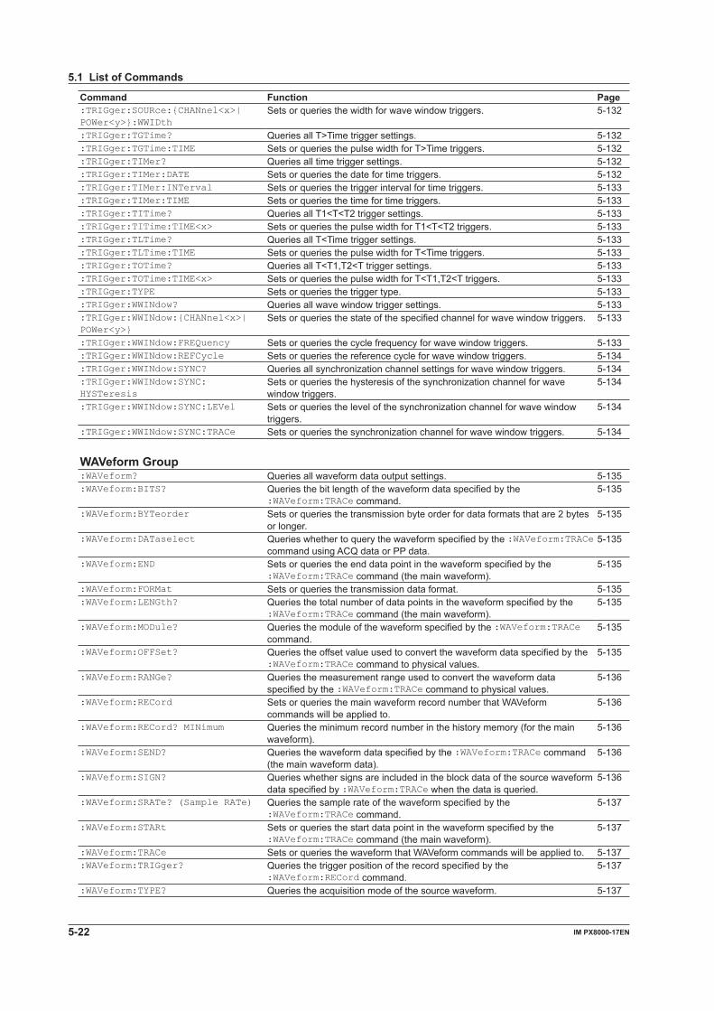
5-22 IM PX8000-17EN
5.1 List of Commands
Command Function Page:TRIGger:SOURce:{CHANnel<x>| POWer<y>}:WWIDth
Sets or queries the width for wave window triggers. 5-132
:TRIGger:TGTime? Queries all T>Time trigger settings. 5-132:TRIGger:TGTime:TIME Sets or queries the pulse width for T>Time triggers. 5-132:TRIGger:TIMer? Queries all time trigger settings. 5-132:TRIGger:TIMer:DATE Sets or queries the date for time triggers. 5-132:TRIGger:TIMer:INTerval Sets or queries the trigger interval for time triggers. 5-133:TRIGger:TIMer:TIME Sets or queries the time for time triggers. 5-133:TRIGger:TITime? Queries all T1<T<T2 trigger settings. 5-133:TRIGger:TITime:TIME<x> Sets or queries the pulse width for T1<T<T2 triggers. 5-133:TRIGger:TLTime? Queries all T<Time trigger settings. 5-133:TRIGger:TLTime:TIME Sets or queries the pulse width for T<Time triggers. 5-133:TRIGger:TOTime? Queries all T<T1,T2<T trigger settings. 5-133:TRIGger:TOTime:TIME<x> Sets or queries the pulse width for T<T1,T2<T triggers. 5-133:TRIGger:TYPE Sets or queries the trigger type. 5-133:TRIGger:WWINdow? Queries all wave window trigger settings. 5-133:TRIGger:WWINdow:{CHANnel<x>| POWer<y>}
Sets or queries the state of the specified channel for wave window triggers. 5-133
:TRIGger:WWINdow:FREQuency Sets or queries the cycle frequency for wave window triggers. 5-133:TRIGger:WWINdow:REFCycle Sets or queries the reference cycle for wave window triggers. 5-134:TRIGger:WWINdow:SYNC? Queries all synchronization channel settings for wave window triggers. 5-134:TRIGger:WWINdow:SYNC: HYSTeresis
Sets or queries the hysteresis of the synchronization channel for wave window triggers.
5-134
:TRIGger:WWINdow:SYNC:LEVel Sets or queries the level of the synchronization channel for wave window triggers.
5-134
:TRIGger:WWINdow:SYNC:TRACe Sets or queries the synchronization channel for wave window triggers. 5-134 WAVeform Group:WAVeform? Queries all waveform data output settings. 5-135:WAVeform:BITS? Queries the bit length of the waveform data specified by the
:WAVeform:TRACe command.5-135
:WAVeform:BYTeorder Sets or queries the transmission byte order for data formats that are 2 bytes or longer.
5-135
:WAVeform:DATaselect Queries whether to query the waveform specified by the :WAVeform:TRACe command using ACQ data or PP data.
5-135
:WAVeform:END Sets or queries the end data point in the waveform specified by the :WAVeform:TRACe command (the main waveform).
5-135
:WAVeform:FORMat Sets or queries the transmission data format. 5-135:WAVeform:LENGth? Queries the total number of data points in the waveform specified by the
:WAVeform:TRACe command (the main waveform).5-135
:WAVeform:MODule? Queries the module of the waveform specified by the :WAVeform:TRACe command.
5-135
:WAVeform:OFFSet? Queries the offset value used to convert the waveform data specified by the :WAVeform:TRACe command to physical values.
5-135
:WAVeform:RANGe? Queries the measurement range used to convert the waveform data specified by the :WAVeform:TRACe command to physical values.
5-136
:WAVeform:RECord Sets or queries the main waveform record number that WAVeform commands will be applied to.
5-136
:WAVeform:RECord? MINimum Queries the minimum record number in the history memory (for the main waveform).
5-136
:WAVeform:SEND? Queries the waveform data specified by the :WAVeform:TRACe command (the main waveform data).
5-136
:WAVeform:SIGN? Queries whether signs are included in the block data of the source waveform data specified by :WAVeform:TRACe when the data is queried.
5-136
:WAVeform:SRATe? (Sample RATe) Queries the sample rate of the waveform specified by the :WAVeform:TRACe command.
5-137
:WAVeform:STARt Sets or queries the start data point in the waveform specified by the :WAVeform:TRACe command (the main waveform).
5-137
:WAVeform:TRACe Sets or queries the waveform that WAVeform commands will be applied to. 5-137:WAVeform:TRIGger? Queries the trigger position of the record specified by the
:WAVeform:RECord command.5-137
:WAVeform:TYPE? Queries the acquisition mode of the source waveform. 5-137
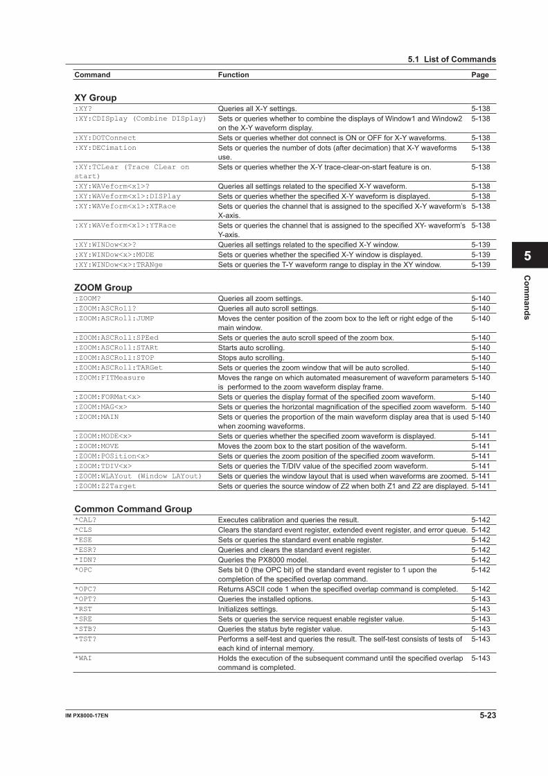
5-23IM PX8000-17EN
Com
mands
1
2
3
4
5
6
App
Index
5.1 List of Commands
Command Function Page XY Group:XY? Queries all X-Y settings. 5-138:XY:CDISplay (Combine DISplay) Sets or queries whether to combine the displays of Window1 and Window2
on the X-Y waveform display.5-138
:XY:DOTConnect Sets or queries whether dot connect is ON or OFF for X-Y waveforms. 5-138:XY:DECimation Sets or queries the number of dots (after decimation) that X-Y waveforms
use.5-138
:XY:TCLear (Trace CLear on start)
Sets or queries whether the X-Y trace-clear-on-start feature is on. 5-138
:XY:WAVeform<x1>? Queries all settings related to the specified X-Y waveform. 5-138:XY:WAVeform<x1>:DISPlay Sets or queries whether the specified X-Y waveform is displayed. 5-138:XY:WAVeform<x1>:XTRace Sets or queries the channel that is assigned to the specified X-Y waveform’s
X-axis.5-138
:XY:WAVeform<x1>:YTRace Sets or queries the channel that is assigned to the specified XY- waveform’s Y-axis.
5-138
:XY:WINDow<x>? Queries all settings related to the specified X-Y window. 5-139:XY:WINDow<x>:MODE Sets or queries whether the specified X-Y window is displayed. 5-139:XY:WINDow<x>:TRANge Sets or queries the T-Y waveform range to display in the XY window. 5-139 ZOOM Group:ZOOM? Queries all zoom settings. 5-140:ZOOM:ASCRoll? Queries all auto scroll settings. 5-140:ZOOM:ASCRoll:JUMP Moves the center position of the zoom box to the left or right edge of the
main window.5-140
:ZOOM:ASCRoll:SPEed Sets or queries the auto scroll speed of the zoom box. 5-140:ZOOM:ASCRoll:STARt Starts auto scrolling. 5-140:ZOOM:ASCRoll:STOP Stops auto scrolling. 5-140:ZOOM:ASCRoll:TARGet Sets or queries the zoom window that will be auto scrolled. 5-140:ZOOM:FITMeasure Moves the range on which automated measurement of waveform parameters
is performed to the zoom waveform display frame.5-140
:ZOOM:FORMat<x> Sets or queries the display format of the specified zoom waveform. 5-140:ZOOM:MAG<x> Sets or queries the horizontal magnification of the specified zoom waveform. 5-140:ZOOM:MAIN Sets or queries the proportion of the main waveform display area that is used
when zooming waveforms.5-140
:ZOOM:MODE<x> Sets or queries whether the specified zoom waveform is displayed. 5-141:ZOOM:MOVE Moves the zoom box to the start position of the waveform. 5-141:ZOOM:POSition<x> Sets or queries the zoom position of the specified zoom waveform. 5-141:ZOOM:TDIV<x> Sets or queries the T/DIV value of the specified zoom waveform. 5-141:ZOOM:WLAYout (Window LAYout) Sets or queries the window layout that is used when waveforms are zoomed. 5-141:ZOOM:Z2Target Sets or queries the source window of Z2 when both Z1 and Z2 are displayed. 5-141 Common Command Group*CAL? Executes calibration and queries the result. 5-142*CLS Clears the standard event register, extended event register, and error queue. 5-142*ESE Sets or queries the standard event enable register. 5-142*ESR? Queries and clears the standard event register. 5-142*IDN? Queries the PX8000 model. 5-142*OPC Sets bit 0 (the OPC bit) of the standard event register to 1 upon the
completion of the specified overlap command.5-142
*OPC? Returns ASCII code 1 when the specified overlap command is completed. 5-142*OPT? Queries the installed options. 5-143*RST Initializes settings. 5-143*SRE Sets or queries the service request enable register value. 5-143*STB? Queries the status byte register value. 5-143*TST? Performs a self-test and queries the result. The self-test consists of tests of
each kind of internal memory.5-143
*WAI Holds the execution of the subsequent command until the specified overlap command is completed.
5-143
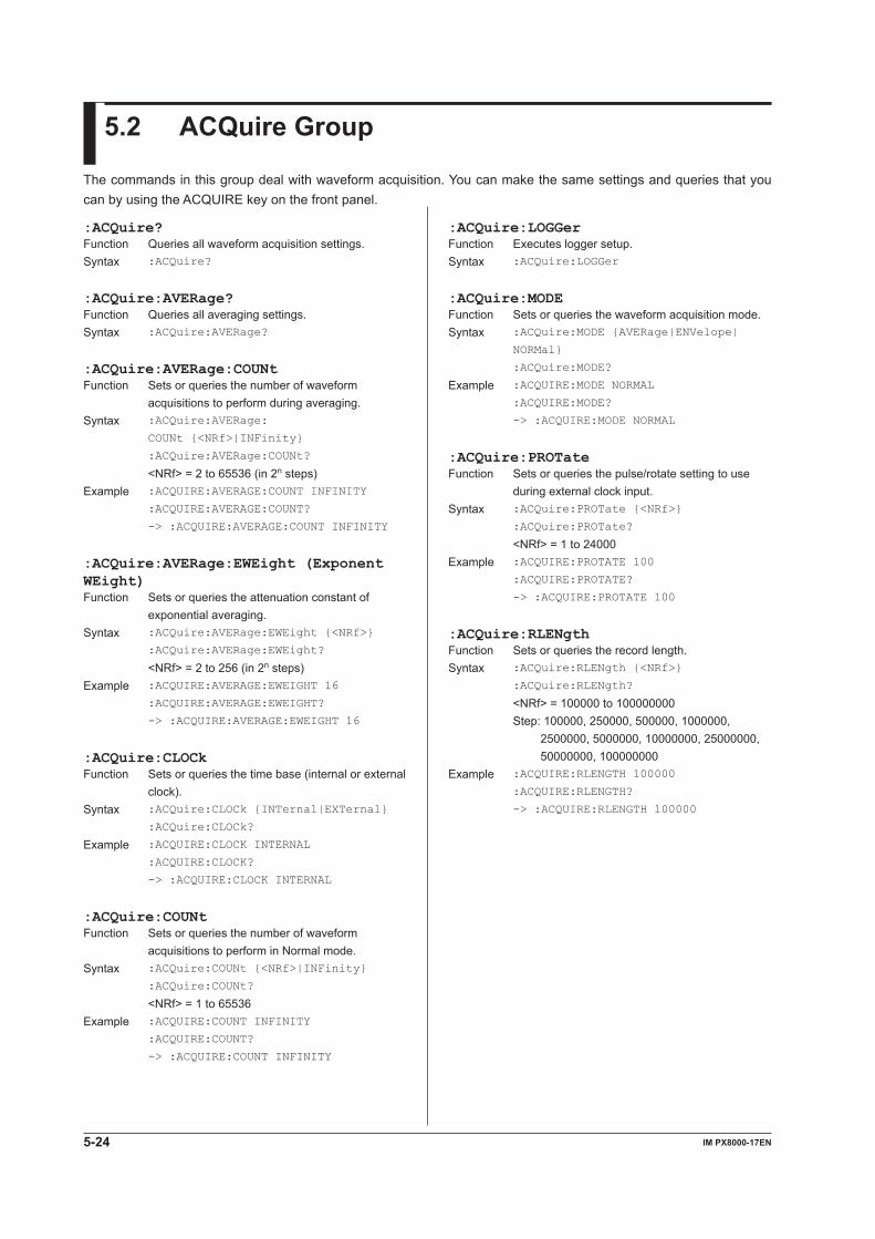
5-24 IM PX8000-17EN
:ACQuire:LOGGerFunction Executes logger setup.Syntax :ACQuire:LOGGer
:ACQuire:MODEFunction Sets or queries the waveform acquisition mode.Syntax :ACQuire:MODE {AVERage|ENVelope|
NORMal}
:ACQuire:MODE?
Example :ACQUIRE:MODE NORMAL
:ACQUIRE:MODE?
-> :ACQUIRE:MODE NORMAL
:ACQuire:PROTateFunction Sets or queries the pulse/rotate setting to use
during external clock input.Syntax :ACQuire:PROTate {<NRf>}
:ACQuire:PROTate?
<NRf> = 1 to 24000Example :ACQUIRE:PROTATE 100
:ACQUIRE:PROTATE?
-> :ACQUIRE:PROTATE 100
:ACQuire:RLENgthFunction Sets or queries the record length.Syntax :ACQuire:RLENgth {<NRf>}
:ACQuire:RLENgth?
<NRf> = 100000 to 100000000 Step: 100000, 250000, 500000, 1000000,
2500000, 5000000, 10000000, 25000000, 50000000, 100000000
Example :ACQUIRE:RLENGTH 100000
:ACQUIRE:RLENGTH?
-> :ACQUIRE:RLENGTH 100000
:ACQuire?Function Queries all waveform acquisition settings.Syntax :ACQuire?
:ACQuire:AVERage?Function Queries all averaging settings.Syntax :ACQuire:AVERage?
:ACQuire:AVERage:COUNtFunction Sets or queries the number of waveform
acquisitions to perform during averaging.Syntax :ACQuire:AVERage:
COUNt {<NRf>|INFinity}
:ACQuire:AVERage:COUNt?
<NRf> = 2 to 65536 (in 2n steps)Example :ACQUIRE:AVERAGE:COUNT INFINITY
:ACQUIRE:AVERAGE:COUNT?
-> :ACQUIRE:AVERAGE:COUNT INFINITY
:ACQuire:AVERage:EWEight (Exponent WEight)Function Sets or queries the attenuation constant of
exponential averaging.Syntax :ACQuire:AVERage:EWEight {<NRf>}
:ACQuire:AVERage:EWEight?
<NRf> = 2 to 256 (in 2n steps)Example :ACQUIRE:AVERAGE:EWEIGHT 16
:ACQUIRE:AVERAGE:EWEIGHT?
-> :ACQUIRE:AVERAGE:EWEIGHT 16
:ACQuire:CLOCkFunction Sets or queries the time base (internal or external
clock).Syntax :ACQuire:CLOCk {INTernal|EXTernal}
:ACQuire:CLOCk?
Example :ACQUIRE:CLOCK INTERNAL
:ACQUIRE:CLOCK?
-> :ACQUIRE:CLOCK INTERNAL
:ACQuire:COUNtFunction Sets or queries the number of waveform
acquisitions to perform in Normal mode.Syntax :ACQuire:COUNt {<NRf>|INFinity}
:ACQuire:COUNt?
<NRf> = 1 to 65536Example :ACQUIRE:COUNT INFINITY
:ACQUIRE:COUNT?
-> :ACQUIRE:COUNT INFINITY
5.2 ACQuire Group
The commands in this group deal with waveform acquisition. You can make the same settings and queries that you can by using the ACQUIRE key on the front panel.
5-25IM PX8000-17EN
Com
mand
1
2
3
4
5
6
App
Index
:CALibrate?Function Queries all calibration settings.Syntax :CALibrate?
:CALibrate:AUXiliary:MODEFunction Sets or queries the AUX module’s auto calibration
mode.Syntax CALibrate:AUXiliary:MODE {AUTO|OFF}
Example :CALIBRATE:AUXILIARY:MODE AUTO
:CALIBRATE:AUXILIARY:MODE?
-> :CALIBRATE:AUXILIARY:MODE AUTO
:CALibrate:ELEMent:MODEFunction Sets or queries the power measurement
element’s auto calibration mode.Syntax :CALibrate:ELEMent:MODE {<Boolean>}
Example :CALIBRATE:ELEMENT:MODE ON
:CALIBRATE:ELEMENT:MODE?
-> :CALIBRATE:ELEMENT:MODE ON
:CALibrate[:EXECute]Function Executes calibration. This command is different from the common
command *CAL? in that this command does not return the results when the calibration is completed.
This is an overlap command.Syntax :CALibrate[:EXECute]
5.3 CALibrate Group
The commands in this group deal with calibration. You can perform the same operations and make the same settings and queries that you can by using the CAL (SHIFT+DISPLAY MODE) keys on the front panel.
5-26 IM PX8000-17EN
5.4 CHANnel Group
The commands in this group deal with a channel’s vertical axis. You can make the same settings and queries that you can by using the VERTICAL group keys (ELEM, U, I, and P keys) on the front panel.
:CHANnel<x>?Function Queries all vertical axis settings of a channel.Syntax :CHANnel<x>?
:CHANnel<x>:DISPlayFunction Sets or queries whether the channel is displayed.Syntax :CHANnel<x>:DISPlay {<Boolean>}
:CHANnel<x>:DISPlay?
<x> = 1 to 8Example :CHANNEL1:DISPLAY 1
:CHANNEL1:DISPLAY?
-> :CHANNEL1:DISPLAY 1
Description Error 241, “Hardware missing,” will occur if there is no module installed in the slot that corresponds to the specified channel.
:CHANnel<x>:LABelFunction Sets or queries the waveform label of a channel.Syntax :CHANnel<x>:LABel {<String>}
:CHANnel<x>:LABel?
<x> = 1 to 8 <String> = Up to 16 charactersExample :CHANNEL5:LABEL "ABC"
:CHANNEL5:LABEL?
-> :CHANNEL5:LABEL "ABC"
:CHANnel<x>:MODUle?Function Queries the module that is installed in the
channel.Syntax :CHANnel<x>:MODUle?
<x> = 1 to 8Example :CHANNEL5:LABEL "ABC"
:CHANNEL1:MODULE?
-> :CHANNEL1:MODULE M760811
Description Values that are returned from each moduleNOMODULE No moduleM760811 Voltage moduleM760812 Current moduleM760813 Current moduleM760851 AUX module
:CHANnel<x>:SENSeFunction Sets or queries the sense type of the AUX
module.Syntax :CHANnel<x>:SENSe {ANALog|PULSe}
Description This command is valid only when the AUX module is installed. You cannot use this command on a voltage or current module.
:CHANnel<x>[:VOLTage]?Function Queries all settings of voltage, current, and AUX
modules.Syntax :CHANnel<x>[:VOLTage]?
:CHANnel<x>[:VOLTage]:AUTOFunction Sets or queries the auto range on/off status of a
channel.Syntax :CHANnel<x>[:VOLTage]:
AUTO {<Boolean>}
:CHANnel<x>[:VOLTage]:AUTO?
<x> = 1 to 8Description :CHANNEL1:VOLTAGE:AUTO ON :CHANNEL1:VOLTAGE:AUTO?
->:CHANNEL1:VOLTAGE:AUTO 1
:CHANnel<x>[:VOLTage]:BWIDthFunction Sets or queries the bandwidth limit of the AUX
module.Syntax :CHANnel<x>[:VOLTage]:
BWIDth {FULL|<Frequency>}
:CHANnel<x>[:VOLTage]:BWIDth?
<x> = 1 to 8 <Frequency> = 10 kHz, 20 kHz, 40 kHz, 80 kHz,
160 kHz, 320 kHz, 640 kHz, 1.28 MHz, 2 MHz
Example :CHANNEL2:VOLTAGE:BWIDTH FULL
:CHANNEL2:VOLTAGE:BWIDTH?
-> :CHANNEL2:VOLTAGE:BWIDTH FULL
Description This command is valid only when the AUX module is installed. You cannot use this command on a voltage or current module.
:CHANnel<x>[:VOLTage]:COUPlingFunction Sets or queries the input coupling setting of the
AUX module.Syntax :CHANnel<x>[:VOLTage]:
COUPling {AC|DC|GND}
:CHANnel<x>[:VOLTage]:COUPling?
<x> = 1 to 8Example :CHANNEL3:VOLTAGE:COUPLING DC
:CHANNEL3:VOLTAGE:COUPLING?
-> :CHANNEL3:VOLTAGE:COUPLING DC
Description • The input coupling is fixed at DC for voltage or current modules. You cannot change it.
• On the AUX module, you can use this command only when the sense type is set to ANALog.
5-27IM PX8000-17EN
Com
mand
1
2
3
4
5
6
App
Index
:CHANnel<x>[:VOLTage]:LSCale:DISPlaytype:DECimalnumFunction Sets or queries the decimal place when the linear
scaling mode of the AUX module is on and the display format is Float.
Syntax :CHANnel<x>[:VOLTage]:LSCale:DISPlay
type:DECimalnum {<NRf>|AUTO}
:CHANnel<x>[:VOLTage]:LSCale:DISPlay
type:DECimalnum?
<x> = 1 to 8 <NRf> = 0 to 3Example :CHANNEL3:VOLTAGE:LSCALE:DISPLAYTYPE
:DECIMALNUM AUTO
:CHANNEL3:VOLTAGE:LSCALE:DISPLAYTYPE
:DECIMALNUM?
-> :CHANNEL3:VOLTAGE:LSCALE:DISPLAYT
YPE:DECIMALNUM AUTO
Description This command is valid only when the AUX module is installed. You cannot use this command on a voltage or current module.
:CHANnel<x>[:VOLTage]:LSCale:DISPlaytype:MODEFunction Sets or queries the display mode when the linear
scaling mode of the AUX module is on.Syntax :CHANnel<x>[:VOLTage]:LSCale:DISPlay
type:MODE {EXPonent|FLOating}
:CHANnel<x>[:VOLTage]:LSCale:DISPlay
type:MODE?
<x> = 1 to 8Example :CHANNEL3:VOLTAGE:LSCALE:DISPLAYTYPE
:MODE EXPONENT
:CHANNEL3:VOLTAGE:LSCALE:DISPLAYTYPE
:MODE?
-> :CHANNEL3:VOLTAGE:LSCALE:DISPLAYT
YPE:MODE EXPONENT
Description This command is valid only when the AUX module is installed. You cannot use this command on a voltage or current module.
:CHANnel<x>[:VOLTage]:LSCale?Function Queries all linear scaling settings of voltage,
current, and AUX modules.Syntax :CHANnel<x>[:VOLTage]:LSCale?
:CHANnel<x>[:VOLTage]:LSCale:AVALueFunction Sets or queries scaling coefficient A when the
linear scaling mode of the AUX module is on.Syntax :CHANnel<x>[:VOLTage]:LSCale:
AVALue {<NRf>}
:CHANnel<x>[:VOLTage]:LSCale:AVALue?
<x> = 1 to 8 <NRf> = –9.9999E+30 to –1E–30,
1E–30 to 9.9999E+30Example :CHANNEL3:VOLTAGE:LSCALE:
AVALUE 25.0000E+00
:CHANNEL3:VOLTAGE:LSCALE:AVALUE?
-> :CHANNEL3:VOLTAGE:LSCALE:
AVALUE 25.0000E+00
Description • This command is valid only when the AUX module is installed. You cannot use this command on a voltage or current module.
• The coefficient cannot be set to 0.
:CHANnel<x>[:VOLTage]:LSCale:BVALueFunction Sets or queries offset B when the linear scaling
mode of the AUX module is on.Syntax :CHANnel<x>[:VOLTage]:LSCale:
BVALue {<NRf>}
:CHANnel<x>[:VOLTage]:LSCale:BVALue?
<x> = 1 to 8 <NRf> = –9.9999E+30 to –1E–30, 0,
1E–30 to 9.9999E+30Example :CHANNEL3:VOLTAGE:LSCALE:
BVALUE -25.0000E+00
:CHANNEL3:VOLTAGE:LSCALE:BVALUE?
-> :CHANNEL3:VOLTAGE:LSCALE:
BVALUE 25.0000E+00
Description This command is valid only when the AUX module is installed. You cannot use this command on a voltage or current module.
:CHANnel<x>[:VOLTage]:LSCale:DISPlaytype?Function Queries all the linear-scaling display-type settings
of the AUX module.Syntax :CHANnel<x>[:VOLTage]:LSCale:DISPlay
type?
Description This command is valid only when the AUX module is installed. You cannot use this command on a voltage or current module.
5.4 CHANnel Group
5-28 IM PX8000-17EN
:CHANnel<x>[:VOLTage]:LSCale:DISPlaytype:SUBunitFunction Sets or queries the unit prefix when the linear
scaling mode of the AUX module is on and the display format is Float.
Syntax :CHANnel<x>[:VOLTage]:LSCale:DISPlay
type:SUBunit {AUTO|NONE|PICO|NANO|MI
CRo|MILI|KILO|MEGA|GIGA|TERA}
:CHANnel<x>[:VOLTage]:LSCale:DISPlay
type:SUBunit?
<x> = 1 to 8Example :CHANNEL3:VOLTAGE:LSCALE:DISPLAYTYPE
:SUBUNIT AUTO
:CHANNEL3:VOLTAGE:LSCALE:DISPLAYTYPE
:SUBUNIT?
-> :CHANNEL3:VOLTAGE:LSCALE:DISPLAYT
YPE:SUBUNIT AUTO
Description This command is valid only when the AUX module is installed. You cannot use this command on a voltage or current module.
:CHANnel<x>[:VOLTage]:LSCale:GETMeasureFunction Executes the measurement of P1:X and P2:X
values when the linear scaling mode of the AUX module is on.
Syntax :CHANnel<x>[:VOLTage]:LSCale:GETMeas
ure {P1X|P2X}
<x> = 1 to 8Description This command is valid only when the AUX module
is installed. You cannot use this command on a voltage or current module.
:CHANnel<x>[:VOLTage]:LSCale:MODEFunction Sets or queries the linear scaling function of the
AUX module.Syntax :CHANnel<x>[:VOLTage]:LSCale:
MODE {AXB|OFF|P12}
:CHANnel<x>[:VOLTage]:LSCale:MODE?
<x> = 1 to 8Example :CHANNEL3:VOLTAGE:LSCALE:MODE AXB
:CHANNEL3:VOLTAGE:LSCALE:MODE?
-> :CHANNEL3:VOLTAGE:LSCALE:MODE OFF
Description This command is valid only when the AUX module is installed. You cannot use this command on a voltage or current module.
:CHANnel<x>[:VOLTage]:LSCale:{P1X|P1Y|P2X|P2Y}Function Sets or queries the measured values (P1:X and
P2:X) and scaling values (P1:Y and P2:Y) when the linear scaling mode of the AUX mode is on.
Syntax :CHANnel<x>[:VOLTage]:LSCale:{P1X|P1
Y|P2X|P2Y} {<NRf>}
:CHANnel<x>[:VOLTage]:LSCale:{P1X|
P1Y|P2X|P2Y}?
<x> = 1 to 8 <NRf> of P1X or P2X
= –9.9999E+30 to –1E–30, 0, 1E–30 to 9.9999E+30 <NRf> of P1Y or P2Y
= –9.9999E+30 to –1E–30, 0, 1E–30 to 9.9999E+30Example :CHANNEL3:VOLTAGE:LSCALE:P1X 1
:CHANNEL3:VOLTAGE:LSCALE:P1X?
-> :CHANNEL3:VOLTAGE:LSCALE:P1X 1
Description This command is valid only when the AUX module is installed. You cannot use this command on a voltage or current module.
:CHANnel<x>[:VOLTage]:LSCale:UNITFunction Sets or queries the linear scaling unit of the AUX
module.Syntax :CHANnel<x>[:VOLTage]:LSCale:
UNIT {<String>}
:CHANnel<x>[:VOLTage]:LSCale:UNIT?
<x> = 1 to 8 <String> = Up to 4 charactersExample :CHANNEL3:VOLTAGE:LSCALE:UNIT "UU"
:CHANNEL3:VOLTAGE:LSCALE:UNIT?
-> :CHANNEL3:VOLTAGE:LSCALE:
UNIT "UU"
Description This command is valid only when the AUX module is installed. You cannot use this command on a voltage or current module.
:CHANnel<x>[:VOLTage]:OFFSetFunction Sets or queries the offset voltage of a voltage,
current, or AUX module.Syntax :CHANnel<x>[:VOLTage]:
OFFSet {<Voltage>|<Current>}
:CHANnel<x>[:VOLTage]:OFFSet?
<x> = 1 to 8 <Voltage> and <Current>
= The selectable range varies depending on the range setting.
Example :CHANNEL3:VOLTAGE:OFFSET 0
:CHANNEL3:VOLTAGE:OFFSET?
-> :CHANNEL3:VOLTAGE:
OFFSET 1.00000E+00
5.4 CHANnel Group
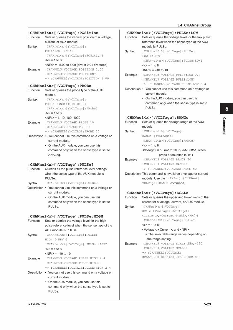
5-29IM PX8000-17EN
Com
mand
1
2
3
4
5
6
App
Index
:CHANnel<x>[:VOLTage]:POSitionFunction Sets or queries the vertical position of a voltage,
current, or AUX module.Syntax :CHANnel<x>[:VOLTage]:
POSition {<NRf>}
:CHANnel<x>[:VOLTage]:POSition?
<x> = 1 to 8 <NRf> = –5.00 to 5.00 (div; in 0.01 div steps)Example :CHANNEL3:VOLTAGE:POSITION 1.00
:CHANNEL3:VOLTAGE:POSITION?
-> :CHANNEL3:VOLTAGE:POSITION 1.00
:CHANnel<x>[:VOLTage]:PROBeFunction Sets or queries the probe type of the AUX
module.Syntax :CHANnel<x>[:VOLTage]:
PROBe {<NRf>|C10|C100}
:CHANnel<x>[:VOLTage]:PROBe?
<x> = 1 to 8 <NRf> = 1, 10, 100, 1000Example :CHANNEL3:VOLTAGE:PROBE 10
:CHANNEL3:VOLTAGE:PROBE?
-> :CHANNEL3:VOLTAGE:PROBE 10
Description • You cannot use this command on a voltage or current module.
• On the AUX module, you can use this command only when the sense type is set to ANALog.
:CHANnel<x>[:VOLTage]:PULSe?Function Queries all the pulse reference level settings
when the sense type of the AUX module is PULSe.
Syntax :CHANnel<x>[:VOLTage]:PULSe?
Description • You cannot use this command on a voltage or current module.
• On the AUX module, you can use this command only when the sense type is set to PULSe.
:CHANnel<x>[:VOLTage]:PULSe:HIGHFunction Sets or queries the voltage level for the high
pulse reference level when the sense type of the AUX module is PULSe.
Syntax :CHANnel<x>[:VOLTage]:PULSe:
HIGH {<NRf>}
:CHANnel<x>[:VOLTage]:PULSe:HIGH?
<x> = 1 to 8 <NRf> = –10 to 10Example :CHANNEL3:VOLTAGE:PULSE:HIGH 2.4
:CHANNEL3:VOLTAGE:PULSE:HIGH?
-> :CHANNEL3:VOLTAGE:PULSE:HIGH 2.4
Description • You cannot use this command on a voltage or current module.
• On the AUX module, you can use this command only when the sense type is set to PULSe.
:CHANnel<x>[:VOLTage]:PULSe:LOWFunction Sets or queries the voltage level for the low pulse
reference level when the sense type of the AUX module is PULSe.
Syntax :CHANnel<x>[:VOLTage]:PULSe:
LOW {<NRf>}
:CHANnel<x>[:VOLTage]:PULSe:LOW?
<x> = 1 to 8 <NRf> = –10 to 10Example :CHANNEL3:VOLTAGE:PULSE:LOW 0.4
:CHANNEL3:VOLTAGE:PULSE:LOW?
-> :CHANNEL3:VOLTAGE:PULSE:LOW 0.4
Description • You cannot use this command on a voltage or current module.
• On the AUX module, you can use this command only when the sense type is set to PULSe.
:CHANnel<x>[:VOLTage]:RANGeFunction Sets or queries the voltage range of the AUX
module.Syntax :CHANnel<x>[:VOLTage]:
RANGe {<Voltage>}
:CHANnel<x>[:VOLTage]:RANGe?
<x> = 1 to 8 <Voltage> = 50 mV to 100 V (M760851, when
probe attenuation is 1:1)Example :CHANNEL3:VOLTAGE:RANGE 50
:CHANNEL3:VOLTAGE:RANGE?
-> :CHANNEL3:VOLTAGE:RANGE 50
Description This command is invalid on a voltage or current module. Use the [:INPut]:{CURRent| VOLTage}:RANGe command.
:CHANnel<x>[:VOLTage]:SCALeFunction Sets or queries the upper and lower limits of the
screen for a voltage, current, or AUX module.Syntax :CHANnel<x>[:VOLTage]:
SCALe {<Voltage>,<Voltage>|
<Current>,<Current>|<NRf>,<NRf>}
:CHANnel<x>[:VOLTage]:SCALe?
<x> = 1 to 8 <Voltage>, <Current>, and <NRf>
= The selectable range varies depending on the range setting.
Example :CHANNEL3:VOLTAGE:SCALE 250,-250
:CHANNEL3:VOLTAGE:SCALE?
-> :CHANNEL3:VOLTAGE:
SCALE 250.000E+00,-250.000E+00
5.4 CHANnel Group
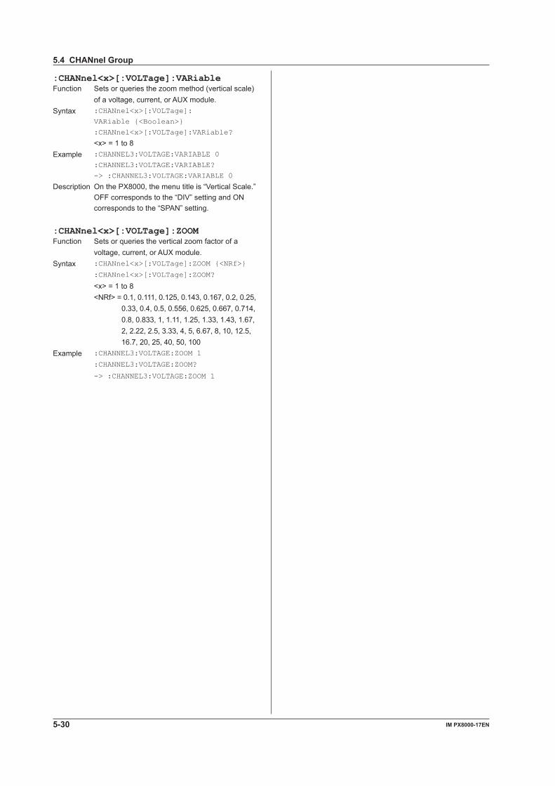
5-30 IM PX8000-17EN
:CHANnel<x>[:VOLTage]:VARiableFunction Sets or queries the zoom method (vertical scale)
of a voltage, current, or AUX module.Syntax :CHANnel<x>[:VOLTage]:
VARiable {<Boolean>}
:CHANnel<x>[:VOLTage]:VARiable?
<x> = 1 to 8Example :CHANNEL3:VOLTAGE:VARIABLE 0
:CHANNEL3:VOLTAGE:VARIABLE?
-> :CHANNEL3:VOLTAGE:VARIABLE 0
Description On the PX8000, the menu title is “Vertical Scale.” OFF corresponds to the “DIV” setting and ON corresponds to the “SPAN” setting.
:CHANnel<x>[:VOLTage]:ZOOMFunction Sets or queries the vertical zoom factor of a
voltage, current, or AUX module.Syntax :CHANnel<x>[:VOLTage]:ZOOM {<NRf>}
:CHANnel<x>[:VOLTage]:ZOOM?
<x> = 1 to 8 <NRf> = 0.1, 0.111, 0.125, 0.143, 0.167, 0.2, 0.25,
0.33, 0.4, 0.5, 0.556, 0.625, 0.667, 0.714, 0.8, 0.833, 1, 1.11, 1.25, 1.33, 1.43, 1.67, 2, 2.22, 2.5, 3.33, 4, 5, 6.67, 8, 10, 12.5, 16.7, 20, 25, 40, 50, 100
Example :CHANNEL3:VOLTAGE:ZOOM 1
:CHANNEL3:VOLTAGE:ZOOM?
-> :CHANNEL3:VOLTAGE:ZOOM 1
5.4 CHANnel Group
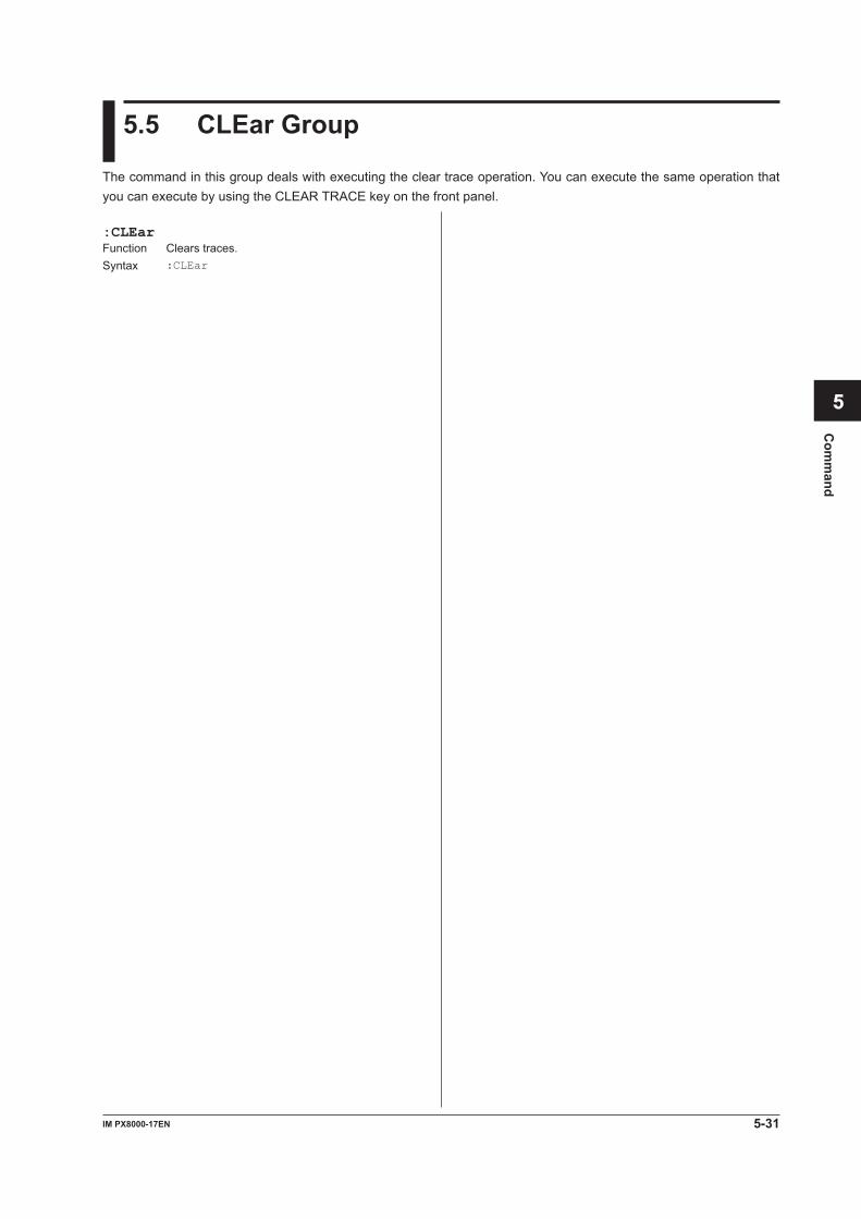
5-31IM PX8000-17EN
Com
mand
1
2
3
4
5
6
App
Index
5.5 CLEar Group
The command in this group deals with executing the clear trace operation. You can execute the same operation that you can execute by using the CLEAR TRACE key on the front panel.
:CLEarFunction Clears traces.Syntax :CLEar
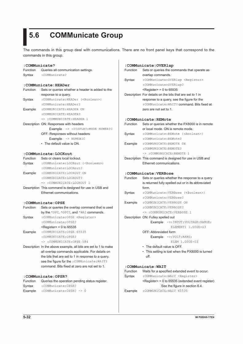
5-32 IM PX8000-17EN
5.6 COMMunicate Group
The commands in this group deal with communications. There are no front panel keys that correspond to the commands in this group.
:COMMunicate?Function Queries all communication settings.Syntax :COMMunicate?
:COMMunicate:HEADerFunction Sets or queries whether a header is added to the
response to a query. Syntax :COMMunicate:HEADer {<Boolean>}
:COMMunicate:HEADer?
Example :COMMUNICATE:HEADER ON
:COMMUNICATE:HEADER?
-> :COMMUNICATE:HEADER 1
Description ON: Responses with headers Example -> :DISPLAY:MODE NUMERIC
OFF: Responses without headers Example -> NUMERIC
• The default value is ON.
:COMMunicate:LOCKoutFunction Sets or clears local lockout.Syntax :COMMunicate:LOCKout {<Boolean>}
:COMMunicate:LOCKout?
Example :COMMUNICATE:LOCKOUT ON
:COMMUNICATE:LOCKOUT?
-> :COMMUNICATE:LOCKOUT 1
Description This command is designed for use in USB and Ethernet communications.
:COMMunicate:OPSEFunction Sets or queries the overlap command that is used
by the *OPC, *OPC?, and *WAI commands.Syntax :COMMunicate:OPSE <Register>
:COMMunicate:OPSE?
<Register> = 0 to 65535Example :COMMUNICATE:OPSE 65535
:COMMUNICATE:OPSE?
-> :COMMUNICATE:OPSE 584
Description In the above example, all bits are set to 1 to make all overlap commands applicable. For details on the bits that are set to 1 in response to a query, see the figure for the :COMMunicate:WAIT? command. Bits fixed at zero are not set to 1.
:COMMunicate:OPSR?Function Queries the operation pending status register.Syntax :COMMunicate:OPSR?
Example :COMMunicate:OPSR? -> 0
:COMMunicate:OVERlapFunction Sets or queries the commands that operate as
overlap commands.Syntax :COMMunicate:OVERlap <Register>
:COMMunicate:OVERlap?
<Register> = 0 to 65535 Description For details on the bits that are set to 1 in
response to a query, see the figure for the :COMMunicate:WAIT? command. Bits fixed at zero are not set to 1.
:COMMunicate:REMoteFunction Sets or queries whether the PX8000 is in remote
or local mode. ON is remote mode.Syntax :COMMunicate:REMote {<Boolean>}
:COMMunicate:REMote?
Example :COMMUNICATE:REMOTE ON
:COMMUNICATE:REMOTE?
-> :COMMUNICATE:REMOTE 1
Description This command is designed for use in USB and Ethernet communications.
:COMMunicate:VERBoseFunction Sets or queries whether the response to a query
is returned fully spelled out or in its abbreviated form.
Syntax :COMMunicate:VERBose {<Boolean>}
:COMMunicate:VERBose?
Example :COMMUNICATE:VERBOSE ON
:COMMUNICATE:VERBOSE?
-> :COMMUNICATE:VERBOSE 1
Description ON: Fulley spelled out Example -> :INPUT:VOLTAGE:RANGE:
ELEMENT1 1.000E+03
OFF: Abbreviated form Example -> :VOLT:RANG:
ELEM 1.000E+03
• The default value is OFF. • This setting is lost when the PX8000 is turned
off.
:COMMunicate:WAITFunction Waits for a specified extended event to occur.Syntax :COMMunicate:WAIT <Register>
<Register> = 0 to 65535 (extended event register) See the figure in section 6.4.
Example :COMMUNICATE:WAIT 65535
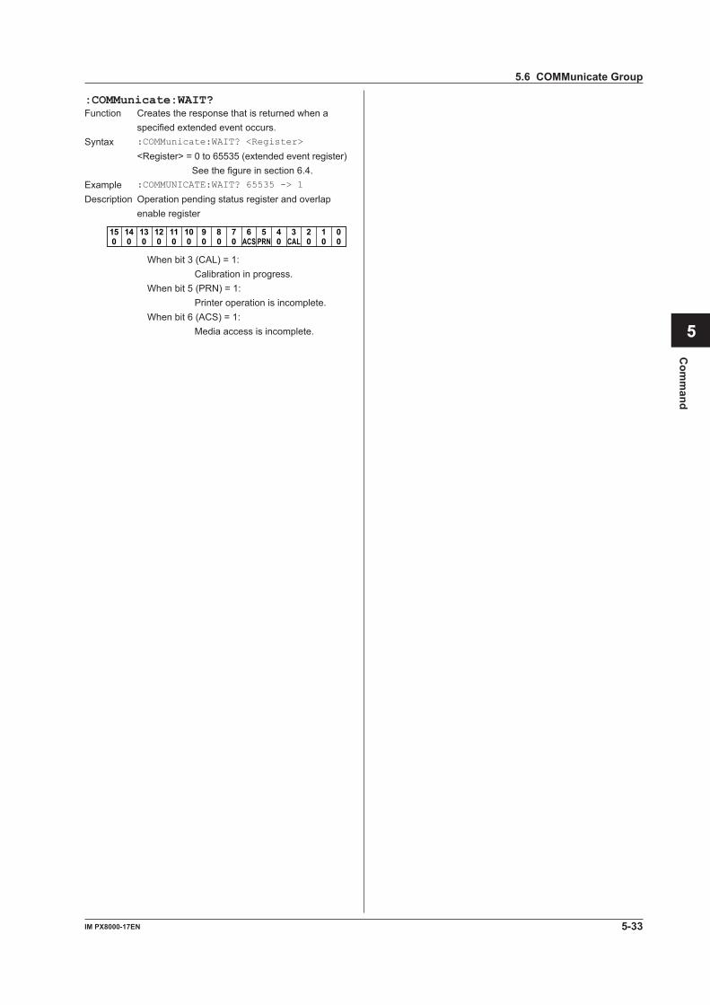
5-33IM PX8000-17EN
Com
mand
1
2
3
4
5
6
App
Index
:COMMunicate:WAIT?Function Creates the response that is returned when a
specified extended event occurs.Syntax :COMMunicate:WAIT? <Register>
<Register> = 0 to 65535 (extended event register) See the figure in section 6.4.
Example :COMMUNICATE:WAIT? 65535 -> 1
Description Operation pending status register and overlap enable register
15 14 13 12 11 10 9 8 7 6 5 4 3 2 1 00 0 0 0 0 0 0 0 0 ACS 0 CAL 0 0 0PRN
When bit 3 (CAL) = 1: Calibration in progress.
When bit 5 (PRN) = 1: Printer operation is incomplete.
When bit 6 (ACS) = 1: Media access is incomplete.
5.6 COMMunicate Group
5-34 IM PX8000-17EN
5.7 CURSor Group
The commands in this group deal with cursor measurements. You can make the same settings and queries (of settings and measured values) that you can by using the CURSOR key on the front panel.If the selectable range of the time axis is “<NRf> = –5 to 5div,” the selectable range varies depending on settings such as the record length. For details, see “Selectable Range of Cursor Positions” under “Notes about Cursor Measurement” in chapter 15 of IM PX8000-01EN.
:CURSor:FFT:MARKer:M<x>:DF<y>:VALue?Function QueriestheΔFvaluebetweentheFFTcursors
(marker cursors).Syntax :CURSor:FFT:MARKer:M<x>:DF<y>:VALue?
<x> = 1 to 4 <y> = 1 to 4Example :CURSOR:FFT:MARKER:M1:DF2:VALUE?
-> :CURSOR:FFT:MARKER:M1:DF2:
VALUE 100
:CURSor:FFT:MARKer:M<x>:DY<y>?Function QueriesallΔYdisplaysettings.ΔYisbetweenthe
FFT cursors (marker cursors).Syntax :CURSor:FFT:MARKer:M<x>:DY<y>?
<x> = 1 to 4 <y> = 1 to 4
:CURSor:FFT:MARKer:M<x>:DY<y>:STATeFunction SetsorquerieswhethertheΔYvaluebetween
the FFT cursors (marker cursors) is displayed.Syntax :CURSor:FFT:MARKer:M<x>:DY<y>:
STATe {<Boolean>}
:CURSor:FFT:MARKer:M<x>:DY<y>:STATe?
<x> = 1 to 4 <y> = 1 to 4Example :CURSOR:FFT:MARKER:M1:DY2:STATE ON
:CURSOR:FFT:MARKER:M1:DY2:STATE?
-> :CURSOR:FFT:MARKER:M1:DY2:STATE 1
:CURSor:FFT:MARKer:M<x>:DY<y>:VALue?Function QueriestheΔYvaluebetweentheFFTcursors
(marker cursors).Syntax :CURSor:FFT:MARKer:M<x>:DY<y>:VALue?
<x> = 1 to 4 <y> = 1 to 4Example :CURSOR:FFT:MARKER:M1:DY2:VALUE?
-> :CURSOR:FFT:MARKER:M1:DY2:
VALUE 3.9750000E+00
:CURSor?Function Queries all cursor measurement settings.Syntax :CURSor?
:CURSor:FFT?Function Queries all FFT cursor settings.Syntax :CURSor:FFT?
:CURSor:FFT:MARKer:FORMFunction Sets or queries the form of an FFT cursor (marker
cursor).Syntax :CURSor:FFT:MARKer:FORM {LINE|MARK}
:CURSor:FFT:MARKer:FORM?
Example :CURSOR:FFT:MARKER:FORM LINE
:CURSOR:FFT:MARKER:FORM?
-> :CURSOR:FFT:MARKER:FORM LINE
:CURSor:FFT:MARKer:M<x>?Function Queries all settings of an FFT cursor (marker
cursor).Syntax :CURSor:FFT:MARKer:M<x>?
<x> = 1 to 4
:CURSor:FFT:MARKer:M<x>:DF<y>?Function QueriesallΔFdisplaysettings.ΔFisbetweenthe
FFT cursors (marker cursors). <x> = 1 to 4 <y> = 1 to 4
:CURSor:FFT:MARKer:M<x>:DF<y>:STATeFunction SetsorquerieswhethertheΔFvaluebetween
the FFT cursors (marker cursors) is displayed.Syntax :CURSor:FFT:MARKer:M<x>:DF<y>:
STATe {<Boolean>}
:CURSor:FFT:MARKer:M<x>:DF<y>:STATe?
<x> = 1 to 4 <y> = 1 to 4Example :CURSOR:FFT:MARKER:M1:DF2:STATE ON
:CURSOR:FFT:MARKER:M1:DF2:STATE?
-> :CURSOR:FFT:MARKER:M1:DF2:STATE 1
5-35IM PX8000-17EN
Com
mand
1
2
3
4
5
6
App
Index
:CURSor:FFT:MARKer:M<x>:F?Function Queries all frequency-axis settings of an FFT
cursor (marker cursor).Syntax :CURSor:FFT:MARKer:M<x>:F?
<x> = 1 to 4
:CURSor:FFT:MARKer:M<x>:F:STATeFunction Sets or queries whether the frequency-axis value
of an FFT cursor (marker cursor) is displayed.Syntax :CURSor:FFT:MARKer:M<x>:F:
STATe {<Boolean>}
:CURSor:FFT:MARKer:M<x>:F:STATe?
<x> = 1 to 4Example :CURSOR:FFT:MARKER:M1:F:STATE ON
:CURSOR:FFT:MARKER:M1:F:STATE?
-> :CURSOR:FFT:MARKER:M1:F:STATE 1
:CURSor:FFT:MARKer:M<x>:F:VALue?Function Queries the frequency-axis value of an FFT
cursor (marker cursor).Syntax :CURSor:FFT:MARKer:M<x>:F:VALue?
<x> = 1 to 4Example :CURSOR:FFT:MARKER:M1:F:VALUE?
-> :CURSOR:FFT:MARKER:M1:F:
VALUE 100.00000E+03
:CURSor:FFT:MARKer:M<x>:POSitionFunction Sets or queries the position of an FFT cursor
(marker cursor).Syntax :CURSor:FFT:MARKer:M<x>:
POSition {<NRf>}
:CURSor:FFT:MARKer:M<x>:POSition?
<x> = 1 to 4 <NRf> = –5 to 5Example :CURSOR:FFT:MARKER:M1:POSITION -3.00
:CURSOR:FFT:MARKER:M1:POSITION?
-> :CURSOR:FFT:MARKER:M1:
POSITION -3.00
:CURSor:FFT:MARKer:M<x>:TRACeFunction Sets or queries the source waveform that you
want to measure using the FFT cursor (marker cursor).
Syntax :CURSor:FFT:MARKer:M<x>:TRACe {OFF|
FFT1|FFT2}
:CURSor:FFT:MARKer:M<x>:TRACe?
<x> = 1 to 4Example :CURSOR:FFT:MARKER:M1:TRACE FFT1
:CURSOR:FFT:MARKER:M1:TRACE?
-> :CURSOR:FFT:MARKER:M1:TRACE FFT1
:CURSor:FFT:MARKer:M<x>:Y?Function Queries all Y-axis settings of an FFT cursor
(marker cursor).Syntax :CURSor:FFT:MARKer:M<x>:Y?
<x> = 1 to 4
:CURSor:FFT:MARKer:M<x>:Y:STATeFunction Sets or queries whether the Y-axis value of an
FFT cursor (marker cursor) is displayed.Syntax :CURSor:FFT:MARKer:M<x>:Y:
STATe {<Boolean>}
:CURSor:FFT:MARKer:M<x>:Y:STATe?
<x> = 1 to 4Example :CURSOR:FFT:MARKER:M1:Y:STATE ON
:CURSOR:FFT:MARKER:M1:Y:STATE?
-> :CURSOR:FFT:MARKER:M1:Y:STATE 1
:CURSor:FFT:MARKer:M<x>:Y:VALue?Function Queries the Y-axis value of an FFT cursor (marker
cursor).Syntax :CURSor:FFT:MARKer:M<x>:Y:VALue?
<x> = 1 to 4Example :CURSOR:FFT:MARKER:M1:Y:VALUE?
-> :CURSOR:FFT:MARKER:M1:Y:
VALUE -46.750000E+00
:CURSor:FFT:PEAK<x>?Function Queries all settings of an FFT cursor (peak
cursor).Syntax :CURSor:FFT:PEAK<x>?
<x> = 1, 2 (cursors 1 and 2)Description Cursor 1 is dedicated for use as FFT1. Cursor 2
is dedicated for use as FFT2.
:CURSor:FFT:PEAK<x>:F?Function Queries all frequency-axis settings of an FFT
cursor (peak cursor).Syntax :CURSor:FFT:PEAK<x>:F?
<x> = 1, 2 (cursors 1 and 2)
:CURSor:FFT:PEAK<x>:F:STATeFunction Sets or queries whether the frequency-axis value
of an FFT cursor (peak cursor) is displayed.Syntax :CURSor:FFT:PEAK<x>:F:
STATe {<Boolean>}
:CURSor:FFT:PEAK<x>:F:STATe?
<x> = 1, 2 (cursors 1 and 2)Example :CURSOR:FFT:PEAK1:F:STATE ON
:CURSOR:FFT:PEAK1:F:STATE?
-> :CURSOR:FFT:PEAK1:F:STATE 1
5.7 CURSor Group
5-36 IM PX8000-17EN
:CURSor:FFT:PEAK<x>:F:VALue?Function Queries the frequency-axis value of an FFT
cursor (peak cursor).Syntax :CURSor:FFT:PEAK<x>:F:VALue?
<x> = 1, 2 (cursors 1 and 2)Example :CURSOR:FFT:PEAK1:F:VALUE?
-> :CURSOR:FFT:PEAK1:F:
VALUE 2.0000000E+03
:CURSor:FFT:PEAK<x>:RANGeFunction Sets or queries the FFT peak cursor
measurement range.Syntax :CURSor:FFT:PEAK<x>:
RANGe {<NRf>,<NRf>}
:CURSor:FFT:PEAK<x>:RANGe?
<x> = 1, 2 (cursors 1 and 2) <NRf> = -5 to 5Example :CURSOR:FFT:PEAK1:RANGE -5.00,5.00
:CURSOR:FFT:PEAK1:RANGE?
-> :CURSOR:FFT:PEAK1:RANGE -5.00,5.00
:CURSor:FFT:PEAK<x>:Y?Function Queries all Y-axis settings of an FFT cursor (peak
cursor).Syntax :CURSor:FFT:PEAK<x>:Y?
<x> = 1, 2 (cursors 1 and 2)
:CURSor:FFT:PEAK<x>:Y:STATeFunction Sets or queries whether the Y-axis value of an
FFT cursor (peak cursor) is displayed.Syntax :CURSor:FFT:PEAK<x>:Y:
STATe {<Boolean>}
:CURSor:FFT:PEAK<x>:Y:STATe?
<x> = 1, 2 (cursors 1 and 2)Example :CURSOR:FFT:PEAK2:Y:STATE ON
:CURSOR:FFT:PEAK2:Y:STATE?
-> :CURSOR:FFT:PEAK2:Y:STATE 1
:CURSor:FFT:PEAK<x>:Y:VALue?Function Queries the Y-axis value of an FFT cursor (peak
cursor).Syntax :CURSor:FFT:PEAK<x>:Y:VALue?
<x> = 1, 2 (cursors 1 and 2)Example :CURSOR:FFT:PEAK2:Y:VALUE?
-> :CURSOR:FFT:PEAK2:Y:
VALUE 30.933333E+00
:CURSor:FFT:TYPEFunction Sets or queries the FFT cursor type.Syntax :CURSor:FFT:TYPE {OFF|PEAK|MARKer}
:CURSor:FFT:TYPE?
Example :CURSOR:FFT:TYPE PEAK
:CURSOR:FFT:TYPE?
-> :CURSOR:FFT:TYPE PEAK
:CURSor[:TY]?Function Queries all cursor settings for the T-Y display.Syntax :CURSor[:TY]?
:CURSor[:TY]:DEGRee?Function Queries all angle cursor settings for the T-Y
display.Syntax :CURSor[:TY]:DEGRee?
:CURSor[:TY]:DEGRee:D<x>?Function Queries all angle (X1 and X2) settings for the
angle cursors on the T-Y display.Syntax :CURSor[:TY]:DEGRee:D<x>?
<x> = 1, 2
:CURSor[:TY]:DEGRee:D<x>:STATeFunction Sets or queries whether the angles (X1 and X2)
between the angle cursors on the T-Y display is displayed.
Syntax :CURSor[:TY]:DEGRee:D<x>:
STATe {<Boolean>}
:CURSor[:TY]:DEGRee:D<x>:STATe?
<x> = 1, 2Example :CURSOR:TY:DEGREE:D1:STATE ON
:CURSOR:TY:DEGREE:D1:STATE?
-> :CURSOR:TY:DEGREE:D1:STATE 1
:CURSor[:TY]:DEGRee:D<x>:VALue?Function Queries the angles (X1 and X2) between the
angle cursors on the T-Y display.Syntax :CURSor[:TY]:DEGRee:D<x>:VALue?
<x> = 1, 2Example :CURSOR:TY:DEGREE:D1:VALUE?
-> :CURSOR:TY:DEGREE:D1:
VALUE -179.55000E+00
:CURSor[:TY]:DEGRee:DD?Function Queriesallangledifference(ΔX)settings.The
angle difference is between the angle cursors on the T-Y display.
Syntax :CURSor[:TY]:DEGRee:DD?
:CURSor[:TY]:DEGRee:DD:STATeFunction Setsorquerieswhethertheangledifference(ΔX)
between the angle cursors on the T-Y display is displayed.
Syntax :CURSor[:TY]:DEGRee:DD:
STATe {<Boolean>}
:CURSor[:TY]:DEGRee:DD:STATe?
Example :CURSOR:TY:DEGREE:DD:STATE ON
:CURSOR:TY:DEGREE:DD:STATE?
-> :CURSOR:TY:DEGREE:DD:STATE 1
5.7 CURSor Group
5-37IM PX8000-17EN
Com
mand
1
2
3
4
5
6
App
Index
:CURSor[:TY]:DEGRee:DD:VALue?Function Queriestheangledifference(ΔX)betweenthe
angle cursors on the T-Y display.Syntax :CURSor[:TY]:DEGRee:DD:VALue?
Example :CURSOR:TY:DEGREE:DD:VALUE?
-> :CURSOR:TY:DEGREE:DD:
VALUE 719.55000E+00
:CURSor[:TY]:DEGRee:DY?Function Queriesallmeasurementdifference(ΔY)settings
between the angle cursors on the T-Y display.Syntax :CURSor[:TY]:DEGRee:DY?
:CURSor[:TY]:DEGRee:DY:STATeFunction Sets or queries whether the measurement
difference(ΔY)valuebetweentheanglecursorson the T-Y display is displayed.
Syntax :CURSor[:TY]:DEGRee:DY:
STATe {<Boolean>}
:CURSor[:TY]:DEGRee:DY:STATe?
Example :CURSOR:TY:DEGREE:DY:STATE ON
:CURSOR:TY:DEGREE:DY:STATE?
-> :CURSOR:TY:DEGREE:DY:STATE 1
:CURSor[:TY]:DEGRee:DY:VALue?Function Queriesthemeasurementdifference(ΔY)
between the angle cursors on the T-Y display.Syntax :CURSor[:TY]:DEGRee:DY:VALue?
Example :CURSOR:TY:DEGREE:DY:VALUE?
-> :CURSOR:TY:DEGREE:DY:
VALUE 0.0000000E+00
:CURSor[:TY]:DEGRee:JUMPFunction Moves the specified angle cursor to the center of
the specified zoom window.Syntax :CURSor[:TY]:DEGRee:
JUMP {C1_Z1|C1_Z2|C2_Z1|C2_Z2}
Example :CURSOR:TY:DEGREE:JUMP C1_Z1
Description C1 and C2 are used to indicate Cursor1 and Cursor2.
:CURSor[:TY]:DEGRee:POSition<x>Function Sets or queries an angle cursor position on the
T-Y display.Syntax :CURSor[:TY]:DEGRee:
POSition<x> {<NRf>}
:CURSor[:TY]:DEGRee:POSition<x>?
<x> = 1, 2 <NRf> = –5 to 5 (the resolution depends on the
measurement length)Example :CURSOR:TY:DEGREE:POSITION1 1
:CURSOR:TY:DEGREE:POSITION1?
-> :CURSOR:TY:DEGREE:
POSITION1 1.000000000000
:CURSor[:TY]:DEGRee:REFerence<x>Function Sets or queries the angle reference start (Ref1)
or end (Ref2) point on the T-Y display.Syntax :CURSor[:TY]:DEGRee:
REFerence<x> {<NRf>}
:CURSor[:TY]:DEGRee:REFerence<x>?
<x> = 1, 2 <NRf> = –5 to 5 (the resolution depends on the
measurement length)Example :CURSOR:TY:DEGREE:REFERENCE1 -1
:CURSOR:TY:DEGREE:REFERENCE1?
-> :CURSOR:TY:DEGREE:
REFERENCE1 -1.000000000000
:CURSor[:TY]:DEGRee:RVALueFunction Sets or queries an angle cursor’s reference angle
on the T-Y display.Syntax :CURSor[:TY]:DEGRee:RVALue {<NRf>}
:CURSor[:TY]:DEGRee:RVALue?
<NRf> = 1 to 720 (in steps of 1)Example :CURSOR:TY:DEGREE:RVALUE 360
:CURSOR:TY:DEGREE:RVALUE?
-> :CURSOR:TY:DEGREE:RVALUE 360
:CURSor[:TY]:DEGRee:TRACeFunction Sets or queries the source waveform that you
want to measure using the angle cursors on the T-Y display.
Syntax :CURSor[:TY]:DEGRee:
TRACe {<NRf>|P<y>|MATH<x>|ALL}
:CURSor[:TY]:DEGRee:TRACe?
<NRf> = 1 to 8 <y> = 1 to 4 <x> = 1 to 8Example :CURSOR:TY:DEGREE:TRACE 1
:CURSOR:TY:DEGREE:TRACE?
-> :CURSOR:TY:DEGREE:TRACE 1
:CURSor[:TY]:DEGRee:Y<x>?Function Queries all measurement (Y1 and Y2) settings for
an angle cursor on the T-Y display.Syntax :CURSor[:TY]:DEGRee:Y<x>?
<x> = 1, 2
:CURSor[:TY]:DEGRee:Y<x>:STATeFunction Sets or queries whether the measurements (Y1
and Y2) of an angle cursor on the T-Y display is displayed.
Syntax :CURSor[:TY]:DEGRee:Y<x>:
STATe {<Boolean>}
:CURSor[:TY]:DEGRee:Y<x>:STATe?
<x> = 1, 2Example :CURSOR:TY:DEGREE:Y1:STATE 1
:CURSOR:TY:DEGREE:Y1:STATE?
-> :CURSOR:TY:DEGREE:Y1:STATE 1
5.7 CURSor Group
5-38 IM PX8000-17EN
:CURSor[:TY]:DEGRee:Y<x>:VALue?Function Sets or queries the measurements (Y1 and Y2) of
an angle cursor on the T-Y display.Syntax :CURSor[:TY]:DEGRee:Y<x>:VALue?
<x> = 1, 2Example :CURSOR:TY:DEGREE:Y1:VALUE?
-> :CURSOR:TY:DEGREE:Y1:
VALUE 0.0000000E+00
Description • If you have set the waveform that you want to measure to ALL, all the measured values from the channels, and Math channels of all the installed modules will be returned.
• "NAN" will be returned for any unused channels and channels that do not have modules installed in their corresponding slots.
:CURSor[:TY]:HORizontal?Function Queries all horizontal cursor settings for the T-Y
display.Syntax :CURSor[:TY]:HORizontal?
:CURSor[:TY]:HORizontal:DY?Function QueriesallΔY-axissettingsofthehorizontal
cursors on the T-Y display.Syntax :CURSor[:TY]:HORizontal:DY?
:CURSor[:TY]:HORizontal:DY:STATeFunction SetsorquerieswhethertheΔY-axisvalue
between the horizontal cursors on the T-Y display is displayed.
Syntax :CURSor[:TY]:HORizontal:DY:
STATe {<Boolean>}
:CURSor[:TY]:HORizontal:DY:STATe?
Example :CURSOR:TY:HORIZONTAL:DY:STATE ON
:CURSOR:TY:HORIZONTAL:DY:STATE?
-> :CURSOR:TY:HORIZONTAL:DY:STATE 1
:CURSor[:TY]:HORizontal:DY:VALue?Function QueriestheΔY-axisvalueofthehorizontal
cursors on the T-Y display.Syntax :CURSor[:TY]:HORizontal:DY:VALue?
Example :CURSOR:TY:HORIZONTAL:DY:VALUE?
-> :CURSOR:TY:HORIZONTAL:DY:
VALUE 300.00000E+00
:CURSor[:TY]:HORizontal:POSition<x>Function Sets or queries a horizontal cursor position on the
T-Y display.Syntax :CURSor[:TY]:HORizontal:
POSition<x> {<NRf>}
:CURSor[:TY]:HORizontal:POSition<x>?
<x> = 1, 2 <NRf> = –5 to 5 (in steps of 1/100)Example :CURSOR:TY:HORIZONTAL:POSITION2 -3
:CURSOR:TY:HORIZONTAL:POSITION2?
-> :CURSOR:TY:HORIZONTAL:
POSITION2 -3.00
:CURSor[:TY]:HORizontal:TRACeFunction Sets or queries the source waveform that you
want to measure using the horizontal cursors on the T-Y display.
Syntax :CURSor[:TY]:HORizontal:
TRACe {<NRf>|P<y>|MATH<x>}
:CURSor[:TY]:HORizontal:TRACe?
<NRf> = 1 to 8 <y> = 1 to 4 <x> = 1 to 8Example :CURSOR:TY:HORIZONTAL:TRACE 1
:CURSOR:TY:HORIZONTAL:TRACE?
-> :CURSOR:TY:HORIZONTAL:TRACE 1
:CURSor[:TY]:HORizontal:Y<x>?Function Queries all Y-axis settings of the horizontal cursor
on the T-Y display.Syntax :CURSor[:TY]:HORizontal:Y<x>?
<x> = 1, 2
:CURSor[:TY]:HORizontal:Y<x>:STATeFunction Sets or queries whether the Y-axis value for a
horizontal cursor on the T-Y display is displayed.Syntax :CURSor[:TY]:HORizontal:Y<x>:
STATe {<Boolean>}
:CURSor[:TY]:HORizontal:Y<x>:STATe?
<x> = 1, 2Example :CURSOR:TY:HORIZONTAL:Y1:STATE ON
:CURSOR:TY:HORIZONTAL:Y1:STATE?
-> :CURSOR:TY:HORIZONTAL:Y1:STATE 1
:CURSor[:TY]:HORizontal:Y<x>:VALue?Function Queries the Y-axis value of a horizontal cursor on
the T-Y display.Syntax :CURSor[:TY]:HORizontal:Y<x>:VALue?
<x> = 1, 2Example :CURSOR:TY:HORIZONTAL:Y1:VALUE?
-> :CURSOR:TY:HORIZONTAL:Y1:
VALUE 150.00000E+00
5.7 CURSor Group

5-39IM PX8000-17EN
Com
mand
1
2
3
4
5
6
App
Index
:CURSor[:TY]:MARKer?Function Queries all marker cursor settings for the T-Y
display.Syntax :CURSor[:TY]:MARKer?
:CURSor[:TY]:MARKer:FORMFunction Sets or queries the form of the marker cursors on
the T-Y display.Syntax :CURSor[:TY]:MARKer:FORM {LINE|MARK}
:CURSor[:TY]:MARKer:FORM?
Example :CURSOR:TY:MARKER:FORM MARK
:CURSOR:TY:MARKER:FORM?
-> :CURSOR:TY:MARKER:FORM MARK
:CURSor[:TY]:MARKer:M<x>?Function Queries all settings related to the marker cursor
measurement items for the T-Y display.Syntax :CURSor[:TY]:MARKer:M<x>?
<x> = 1 to 4
:CURSor[:TY]:MARKer:M<x>:DX<y>?Function QueriesallΔXvaluesettings.ΔXisbetweenthe
marker cursors on the T-Y display.Syntax :CURSor[:TY]:MARKer:M<x>:DX<y>?
<x> = 1 to 4 <y> = 1 to 4
:CURSor[:TY]:MARKer:M<x>:DX<y>:STATeFunction SetsorquerieswhethertheΔXvaluebetweenthe
marker cursors on the T-Y display is displayed.Syntax :CURSor[:TY]:MARKer:M<x>:DX<y>:
STATe {<Boolean>}
:CURSor[:TY]:MARKer:M<x>:DX<y>:STA
Te?
<x> = 1 to 4 <y> = 1 to 4Example :CURSOR:TY:MARKER:M1:DX2:STATE ON
:CURSOR:TY:MARKER:M1:DX2:STATE?
-> :CURSOR:TY:MARKER:M1:DX2:STATE 1
:CURSor[:TY]:MARKer:M<x>:DX<y>:VALue?Function QueriestheΔXvaluebetweenthemarkercursors
on the T-Y display.Syntax :CURSor[:TY]:MARKer:M<x>:DX<y>:VAL
ue?
<x> = 1 to 4 <y> = 1 to 4Example :CURSOR:TY:MARKER:M1:DX2:VALUE?
-> :CURSOR:TY:MARKER:M1:DX2:
VALUE 2.0000000E-03
:CURSor[:TY]:MARKer:M<x>:DY<y>?Function QueriesallΔYvaluesettings.ΔYisbetweenthe
marker cursors on the T-Y display.Syntax :CURSor[:TY]:MARKer:M<x>:DY<y>?
<x> = 1 to 4 <y> = 1 to 4
:CURSor[:TY]:MARKer:M<x>:DY<y>:STATeFunction SetsorquerieswhethertheΔYvaluebetweenthe
marker cursors on the T-Y display is displayed.Syntax :CURSor[:TY]:MARKer:M<x>:DY<y>:
STATe {<Boolean>}
:CURSor[:TY]:MARKer:M<x>:DY<y>:STA
Te?
<x> = 1 to 4 <y> = 1 to 4Example :CURSOR:TY:MARKER:M1:DY2:STATE ON
:CURSOR:TY:MARKER:M1:DY2:STATE?
-> :CURSOR:TY:MARKER:M1:DY2:STATE 1
:CURSor[:TY]:MARKer:M<x>:DY<y>:VALue?Function QueriestheΔYvaluebetweenthemarkercursors
on the T-Y display.Syntax :CURSor[:TY]:MARKer:M<x>:DY<y>:VAL
ue?
<x> = 1 to 4 <y> = 1 to 4Example :CURSOR:TY:MARKER:M1:DY2:VALUE?
-> :CURSOR:TY:MARKER:M1:DY2:
VALUE 0.0000000E+00
:CURSor[:TY]:MARKer:M<x>:JUMPFunction Moves the specified marker cursor to the center
of the specified zoom window.Syntax :CURSor[:TY]:MARKer:M<x>:
JUMP {Z1|Z2}
<x> = 1 to 4
:CURSor[:TY]:MARKer:M<x>:POSitionFunction Sets or queries a marker cursor position on the
T-Y display.Syntax :CURSor[:TY]:MARKer:M<x>:
POSition {<NRf>}
:CURSor[:TY]:MARKer:M<x>:POSition?
<x> = 1 to 4 <NRf> = –5 to 5 (in steps of 1/100)Example :CURSOR:TY:MARKER:M1:POSITION -3
:CURSOR:TY:MARKER:M1:POSITION?
-> :CURSOR:TY:MARKER:M1:
POSITION -3.000000000000
5.7 CURSor Group
5-40 IM PX8000-17EN
:CURSor[:TY]:MARKer:M<x>:TRACeFunction Sets or queries the source waveform that you
want to measure using the marker cursors on the T-Y display.
Syntax :CURSor[:TY]:MARKer:M<x>:
TRACe {OFF|<NRf>|P<y>|MATH<x>}
:CURSor[:TY]:MARKer:M<x>:TRACe?
<x> of M<x> = 1 to 4 <NRf> = 1 to 8 <y> = 1 to 4 <x> of MATH<x> = 1 to 8Example :CURSOR:TY:MARKER:M1:TRACE 1
:CURSOR:TY:MARKER:M1:TRACE?
-> :CURSOR:TY:MARKER:M1:TRACE 1
:CURSor[:TY]:MARKer:M<x>:X?Function Queries all X-axis settings for a marker cursor on
the T-Y display.Syntax :CURSor[:TY]:MARKer:M<x>:X?
<x> = 1 to 4
:CURSor[:TY]:MARKer:M<x>:X:STATeFunction Sets or queries whether the X-axis value for a
marker cursor on the T-Y display is displayed.Syntax :CURSor[:TY]:MARKer:M<x>:X:
STATe {<Boolean>}
:CURSor[:TY]:MARKer:M<x>:X:STATe?
<x> = 1 to 4Example :CURSOR:TY:MARKER:M4:X:STATE ON
:CURSOR:TY:MARKER:M4:X:STATE?
-> :CURSOR:TY:MARKER:M4:X:STATE 1
:CURSor[:TY]:MARKer:M<x>:X:VALue?Function Queries the X-axis value of a marker cursor on
the T-Y display.Syntax :CURSor[:TY]:MARKer:M<x>:X:STATe?
<x> = 1 to 4Example :CURSOR:TY:MARKER:M4:X:VALUE?
-> :CURSOR:TY:MARKER:M4:X:
VALUE 3.0000000E-03
:CURSor[:TY]:MARKer:M<x>:Y?Function Queries all Y-axis settings for a marker cursor on
the T-Y display.Syntax :CURSor[:TY]:MARKer:M<x>:Y?
<x> = 1 to 4
:CURSor[:TY]:MARKer:M<x>:Y:STATeFunction Sets or queries whether the Y-axis value for a
marker cursor on the T-Y display is displayed.Syntax :CURSor[:TY]:MARKer:M<x>:Y:
STATe {<Boolean>}
:CURSor[:TY]:MARKer:M<x>:Y:STATe?
<x> = 1 to 4Example :CURSOR:TY:MARKER:M4:Y:STATE ON
:CURSOR:TY:MARKER:M4:Y:STATE?
-> :CURSOR:TY:MARKER:M4:Y:STATE 1
:CURSor[:TY]:MARKer:M<x>:Y:VALue?Function Queries the Y-axis value of a marker cursor on
the T-Y display.Syntax :CURSor[:TY]:MARKer:M<x>:Y:STATe?
<x> = 1 to 4Example :CURSOR:TY:MARKER:M4:Y:VALUE?
-> :CURSOR:TY:MARKER:M4:Y:
VALUE 41.666667E-03
:CURSor[:TY]:TYPEFunction Sets or queries the cursor type on the T-Y display.Syntax :CURSor[:TY]:TYPE {OFF|HORizontal|
VERTical|MARKer|DEGRee|HAVertical}
:CURSor[:TY]:TYPE?
Example :CURSOR:TY:TYPE MARKER
:CURSOR:TY:TYPE?
-> :CURSOR:TY:TYPE MARKER
:CURSor[:TY]:VERTical?Function Queries all vertical cursor settings for the T-Y
display.Syntax :CURSor[:TY]:VERTical?
:CURSor[:TY]:VERTical:DX?Function QueriesallΔXvaluesettings.ΔXisbetweenthe
vertical cursors on the T-Y display.Syntax :CURSor[:TY]:VERTical:DX?
:CURSor[:TY]:VERTical:DX:STATeFunction SetsorquerieswhethertheΔXvaluebetweenthe
vertical cursors on the T-Y display is displayed.Syntax :CURSor[:TY]:VERTical:DX:
STATe {<Boolean>}
:CURSor[:TY]:VERTical:DX:STATe?
Example :CURSOR:TY:VERTICAL:DX:STATE 1
:CURSOR:TY:VERTICAL:DX:STATE?
-> :CURSOR:TY:VERTICAL:DX:STATE 1
:CURSor[:TY]:VERTical:DX:VALue?Function QueriestheΔXvaluebetweentheverticalcursors
on the T-Y display.Syntax :CURSor[:TY]:VERTical:DX:VALue?
Example :CURSOR:TY:VERTICAL:DX:VALUE?
-> :CURSOR:TY:VERTICAL:DX:
VALUE 3.0000000E-03
Description • When the Internal Clock Is Being Used as the Time Base
When measurements are performed in the time domain, this queries the time between markers. When measurements are performed in the frequency domain, this queries the frequency between markers.
• When an External Clock is Being Used as the Time Base
This queries the number of points between marker cursors.
5.7 CURSor Group
5-41IM PX8000-17EN
Com
mand
1
2
3
4
5
6
App
Index
:CURSor[:TY]:VERTical:DY?Function Queries all Y-axis-value settings for vertical
cursors on the T-Y display.Syntax :CURSor[:TY]:VERTical:DY?
:CURSor[:TY]:VERTical:DY:STATeFunction Sets or queries whether the Y-axis value for
vertical cursors on the T-Y display is displayed.Syntax :CURSor[:TY]:VERTical:DY:
STATe {<Boolean>}
:CURSor[:TY]:VERTical:DY:STATe?
Example :CURSOR:TY:VERTICAL:DY:STATE ON
:CURSOR:TY:VERTICAL:DY:STATE?
-> :CURSOR:TY:VERTICAL:DY:STATE 1
:CURSor[:TY]:VERTical:DY:VALue?Function Queries the Y-axis value of vertical cursors on the
T-Y display.Syntax :CURSor[:TY]:VERTical:DY:VALue?
:CURSor[:TY]:VERTical:JUMPFunction Moves the specified vertical cursor to the center
of the specified zoom window.Syntax :CURSor[:TY]:VERTical:
JUMP {C1_Z1|C1_Z2|C2_Z1|C2_Z2}
:CURSor[:TY]:VERTical:PERDt?Function Queries all settings related to the reciprocal of the
time difference between the vertical cursors (1/ΔT)ontheT-Ydisplay.
Syntax :CURSor[:TY]:VERTical:PERDt?
Description 1/ΔTisdisplayedas“1/ΔX”onthePX8000screen.
:CURSor[:TY]:VERTical:PERDt:STATeFunction Sets or queries whether the reciprocal of the time
differencebetweentheverticalcursors(1/ΔT)onthe T-Y display is displayed.
Syntax :CURSor[:TY]:VERTical:PERDt:
STATe {<Boolean>}
:CURSor[:TY]:VERTical:PERDt:STATe?
Example :CURSOR:TY:VERTICAL:PERDT:STATE ON
:CURSOR:TY:VERTICAL:PERDT:STATE?
-> :CURSOR:TY:VERTICAL:PERDT:STATE 1
Description 1/ΔTisdisplayedas“1/ΔX”onthePX8000screen.
:CURSor[:TY]:VERTical:PERDt:VALue?Function Queries the reciprocal of the time difference
betweentheverticalcursors(1/ΔT)ontheT-Ydisplay.
Syntax :CURSor[:TY]:VERTical:PERDt:VALue?
Example :CURSOR:TY:VERTICAL:PERDT:
VALUE 250.00000E+00
Description • If the source waveform is being measured in the frequency domain, “NAN” is returned.
• 1/ΔTisdisplayedas“1/ΔX”onthePX8000screen.
:CURSor[:TY]:VERTical:POSition<x>Function Sets or queries a vertical cursor position on the
T-Y display.Syntax :CURSor[:TY]:VERTical:
POSition<x> {<NRf>}
:CURSor[:TY]:VERTical:POSition<x>?
<x> = 1, 2 <NRf> = –5 to 5 (the resolution depends on the
measurement length)Example :CURSOR:TY:VERTICAL:POSITION2 4
:CURSOR:TY:VERTICAL:POSITION2?
-> :CURSOR:TY:VERTICAL:
POSITION2 4.000000000000
:CURSor[:TY]:VERTical:TRACeFunction Sets or queries the source waveform that you
want to measure using the vertical cursors on the T-Y display.
Syntax :CURSor[:TY]:VERTical:
TRACe {<NRf>|P<y>|MATH<x>|ALL}
:CURSor[:TY]:VERTical:TRACe?
<NRf> = 1 to 8 <y> = 1 to 4 <x> = 1 to 8Example :CURSOR:TY:VERTICAL:TRACE 2
:CURSOR:TY:VERTICAL:TRACE?
-> :CURSOR:TY:VERTICAL:TRACE 2
:CURSor[:TY]:VERTical:X<x>?Function Queries all X-axis-value settings for a vertical
cursor on the T-Y display.Syntax :CURSor[:TY]:VERTical:X<x>?
<x> = 1, 2
:CURSor[:TY]:VERTical:X<x>:STATeFunction Sets or queries whether the X-axis value for a
vertical cursor on the T-Y display is displayed.Syntax :CURSor[:TY]:VERTical:X<x>:
STATe {<Boolean>}
:CURSor[:TY]:VERTical:X<x>:STATe?
<x> = 1, 2Example :CURSOR:TY:VERTICAL:X1:STATE 1
:CURSOR:TY:VERTICAL:X1:STATE?
-> :CURSOR:TY:VERTICAL:X1:STATE 1
5.7 CURSor Group
5-42 IM PX8000-17EN
:CURSor[:TY]:VERTical:X<x>:VALue?Function Queries the X-axis value of a vertical cursor on
the T-Y display.Syntax :CURSor[:TY]:VERTical:X<x>:VALue?
<x> = 1, 2Example :CURSOR:TY:VERTICAL:X1:VALUE?
-> :CURSOR:TY:VERTICAL:X1:
VALUE 0.0000000E+00
Description • When the Internal Clock Is Being Used as the Time Base
When measurements are performed in the time domain, this queries the time. When measurements are performed in the frequency domain, this queries the frequency.
• When an External Clock Is Being Used as the Time Base
When measurements are performed in the time domain, this queries the number of points using the trigger point as the reference. When measurements are performed in the frequency domain, this queries the number of points using the front of the waveform as the reference.
:CURSor[:TY]:VERTical:Y<x>?Function Queries all Y-axis-value settings for a vertical
cursor on the T-Y display.Syntax :CURSor[:TY]:VERTical:Y<x>?
<x> = 1, 2
:CURSor[:TY]:VERTical:Y<x>:STATeFunction Sets or queries whether the Y-axis value for a
vertical cursor on the T-Y display is displayed.Syntax :CURSor[:TY]:VERTical:Y<x>:
STATe {<Boolean>}
:CURSor[:TY]:VERTical:Y<x>?
<x> = 1, 2Example :CURSOR:TY:VERTICAL:Y1:STATE 1
:CURSOR:TY:VERTICAL:Y1:STATE?
-> :CURSOR:TY:VERTICAL:Y1:STATE 1
:CURSor[:TY]:VERTical:Y<x>:VALue?Function Queries the Y-axis value (measured value) of a
vertical cursor on the T-Y display.Syntax :CURSor[:TY]:VERTical:Y<x>:VALue?
<x> = 1, 2Example :CURSOR:TY:VERTICAL:Y2:VALUE?
-> :CURSOR:TY:VERTICAL:Y2:
VALUE -333.33333E-03
Description • If you have set the waveform that you want to measure to ALL, all the measured values from the channels, and Math channels of all the installed modules will be returned.
• "NAN" will be returned for any unused channels and channels that do not have modules installed in their corresponding slots.
:CURSor:WAIT?Function While the PX8000 is waiting for the specified
CURSor command to finish, it will wait the time specified by the :CURSor:WAIT? timeout value until it begins processing the subsequent command.
Syntax :CURSor:WAIT? {<NRf>}
<NRf> = 1 to 36000 (timeout value, in units of 100 msec)
Example :CURSOR:WAIT? 100 -> 1
Description If the CURSor command that is being processed finishes within the specified timeout, this command will return 0. 1 is returned if the CURSor command does not finish within the specified timeout or if no CURSor command is being processed. Even if you make the timeout value long, 0 is returned as soon as the CURSor command finishes.
:CURSor:XY?Function Queries all cursor settings for the X-Y display.Syntax :CURSor:XY?
:CURSor:XY:HORizontal?Function Queries all horizontal cursor settings for the X-Y
display.Syntax :CURSor:XY:HORizontal?
:CURSor:XY:HORizontal:DY?Function QueriesallΔY-axis-valuesettings.TheΔY-axis
value is between the horizontal cursors on the X-Y display.
Syntax :CURSor:XY:HORizontal:DY?
:CURSor:XY:HORizontal:DY:STATeFunction SetsorquerieswhethertheΔY-axisvalue
between the horizontal cursors on the X-Y display is displayed.
Syntax :CURSor:XY:HORizontal:DY:
STATe {<Boolean>}
:CURSor:XY:HORizontal:DY:STATe?
Example :CURSOR:XY:HORIZONTAL:DY:STATE ON
:CURSOR:XY:HORIZONTAL:DY:STATE?
-> :CURSOR:XY:HORIZONTAL:DY:STATE 1
:CURSor:XY:HORizontal:DY:VALue?Function QueriestheΔY-axisvaluebetweenthehorizontal
cursors on the X-Y display.Syntax :CURSor:XY:HORizontal:DY:VALue?
Example :CURSOR:XY:HORIZONTAL:DY:VALUE?
-> :CURSOR:XY:HORIZONTAL:DY:
VALUE 300.00000E+00
5.7 CURSor Group
5-43IM PX8000-17EN
Com
mand
1
2
3
4
5
6
App
Index
:CURSor:XY:HORizontal:POSition<x>Function Sets or queries horizontal cursor positions on the
X-Y display.Syntax :CURSor:XY:HORizontal:
POSition<x> {<NRf>}
:CURSor:XY:HORizontal:POSition<x>?
<x> = 1, 2 <NRf> = –5 to 5 (in steps of 1/100)Example :CURSOR:XY:HORIZONTAL:POSITION1 3
:CURSOR:XY:HORIZONTAL:POSITION1?
-> :CURSOR:XY:HORIZONTAL:
POSITION1 3.00
Description You can query cursor position information for cursors XY1 to XY8. Use the :CURSor:XY:HORizontal:TRACe command to specify the waveform that you want to query.
:CURSor:XY:HORizontal:TRACeFunction Sets or queries the source waveform that you
want to measure using the horizontal cursors on the X-Y display.
Syntax :CURSor:XY:HORizontal:TRACe {XY1|
XY2|XY3|XY4|XY5|XY6|XY7|XY8}
:CURSor:XY:HORizontal:TRACe?
Example :CURSOR:XY:HORIZONTAL:TRACE XY2
:CURSOR:XY:HORIZONTAL:TRACE?
-> :CURSOR:XY:HORIZONTAL:TRACE XY2
:CURSor:XY:HORizontal:Y<x>?Function Queries all Y-axis-value settings for an horizontal
cursor on the X-Y display.Syntax :CURSor:XY:HORizontal:Y<x>?
:CURSor:XY:HORizontal:Y<x>:STATeFunction Sets or queries whether the Y-axis value for an
horizontal cursor on the X-Y display is displayed.Syntax :CURSor:XY:HORizontal:Y<x>:
STATe {<Boolean>}
:CURSor:XY:HORizontal:Y<x>:STATe?
<x> = 1, 2Example :CURSOR:XY:HORIZONTAL:Y1:STATE ON
:CURSOR:XY:HORIZONTAL:Y1:STATE?
-> :CURSOR:XY:HORIZONTAL:Y1:STATE 1
:CURSor:XY:HORizontal:Y<x>:VALue?Function Queries the Y-axis value of an horizontal cursor
on the X-Y display.Syntax :CURSor:XY:HORizontal:Y<x>:VALue?
<x> = 1, 2Example :CURSOR:XY:HORIZONTAL:Y1:VALUE?
-> :CURSOR:XY:HORIZONTAL:Y1:
VALUE 150.00000E+00
:CURSor:XY:MARKer?Function Queries all marker cursor settings for the X-Y
display.Syntax :CURSor:XY:MARKer?
:CURSor:XY:MARKer:FORMFunction Sets or queries the form of the marker cursors on
the X-Y display.Syntax :CURSor:XY:MARKer:FORM {LINE|MARK}
:CURSor:XY:MARKer:FORM?
Example :CURSOR:XY:MARKER:FORM LINE
:CURSOR:XY:MARKER:FORM?
-> :CURSOR:XY:MARKER:FORM LINE
:CURSor:XY:MARKer:M<x>?Function Queries all measurement parameter settings for
the specified marker cursor of the X-Y display.Syntax :CURSor:XY:MARKer:M<x>?
<x> = 1 to 4
:CURSor:XY:MARKer:M<x>:DT<y>?Function Queries all settings related to the time difference
betweenthespecifiedmarkercursors(ΔT)ontheX-Y display.
Syntax :CURSor:XY:MARKer:M<x>:DT<y>?
<x> = 1 to 4 <y> = 1 to 4
:CURSor:XY:MARKer:M<x>:DT<y>:STATeFunction Sets or queries whether the time difference
betweenthespecifiedmarkercursors(ΔT)ontheX-Y display is displayed.
Syntax :CURSor:XY:MARKer:M<x>:DT<y>
:STATe {<Boolean>}
:CURSor:XY:MARKer:M<x>:DT<y>:STATe?
<x> = 1 to 4 <y> = 1 to 4
:CURSor:XY:MARKer:M<x>:DT<y>:VALue?Function Queries the time difference between the specified
markercursors(ΔT)ontheX-Ydisplay.Syntax :CURSor:XY:MARKer:M<x>:DT<y>:VALue?
<x> = 1 to 4 <y> = 1 to 4
5.7 CURSor Group

5-44 IM PX8000-17EN
:CURSor:XY:MARKer:M<x>:POSitionFunction Sets or queries a marker cursor’s time-axis-
equivalent position on the X-Y display.Syntax :CURSor:XY:MARKer:M<x>:
POSition {<NRf>}
:CURSor:XY:MARKer:M<x>:POSition?
<x> = 1 to 4 <NRf> = –5 to 5div (the resolution depends on
the measurement length)Example :CURSOR:XY:MARKER:M1:POSITION -3
:CURSOR:XY:MARKER:M1:POSITION?
-> :CURSOR:XY:MARKER:M1:
POSITION -3.000000000000
:CURSor:XY:MARKer:M<x>:T?Function Queries all time value settings for a marker cursor
on the X-Y display.Syntax :CURSor:XY:MARKer:M<x>:T?
<x> = 1 to 4
:CURSor:XY:MARKer:M<x>:T:STATeFunction Sets or queries whether the time value for a
marker cursor on the X-Y display is displayed.Syntax :CURSor:XY:MARKer:M<x>:T:
STATe {<Boolean>}
:CURSor:XY:MARKer:M<x>:T:STATe?
<x> = 1 to 4Example :CURSOR:XY:MARKER:M1:T:STATE ON
:CURSOR:XY:MARKER:M1:T:STATE?
-> :CURSOR:XY:MARKER:M1:T:STATE 1
:CURSor:XY:MARKer:M<x>:T:VALue?Function Queries the time value of a marker cursor on the
X-Y display.Syntax :CURSor:XY:MARKer:M<x>:T:VALue?
<x> = 1 to 4Example :CURSOR:XY:MARKER:M1:T:VALUE?
-> :CURSOR:XY:MARKER:M1:T:
VALUE -3.0000000E-03
:CURSor:XY:MARKer:M<x>:TRACeFunction Sets or queries the source waveform that you
want to measure using the marker cursors on the X-Y display.
Syntax :CURSor:XY:MARKer:M<x>:TRACe {OFF|
XY1|XY2|XY3|XY4|XY5|XY6|XY7|XY8}
:CURSor:XY:MARKer:M<x>:TRACe?
<x> = 1 to 4Example :CURSOR:XY:MARKER:M1:TRACE XY1
:CURSOR:XY:MARKER:M1:TRACE?
-> :CURSOR:XY:MARKER:M1:TRACE XY1
:CURSor:XY:MARKer:M<x>:X?Function Queries all X-axis-value settings for a marker
cursor on the X-Y display.Syntax :CURSor:XY:MARKer:M<x>:X?
<x> = 1 to 4
:CURSor:XY:MARKer:M<x>:X:STATeFunction Sets or queries whether the X-axis value for a
marker cursor on the X-Y display is displayed.Syntax :CURSor:XY:MARKer:M<x>:X:
STATe {<Boolean>}
:CURSor:XY:MARKer:M<x>:X:STATe?
<x> = 1 to 4Example :CURSOR:XY:MARKER:M1:X:STATE 1
:CURSOR:XY:MARKER:M1:X:STATE?
-> :CURSOR:XY:MARKER:M1:X:STATE 1
:CURSor:XY:MARKer:M<x>:X:VALue?Function Queries the X-axis value of a marker cursor on
the X-Y display.Syntax :CURSor:XY:MARKer:M<x>:X:VALue?
<x> = 1 to 4Example :CURSOR:XY:MARKER:M1:X:VALUE?
-> :CURSOR:XY:MARKER:M1:X:
VALUE 333.33333E-03
:CURSor:XY:MARKer:M<x>:Y?Function Queries all Y-axis-value settings for a marker
cursor on the X-Y display.Syntax :CURSor:XY:MARKer:M<x>:Y?
<x> = 1 to 4
:CURSor:XY:MARKer:M<x>:Y:STATeFunction Sets or queries whether the Y-axis value for a
marker cursor on the X-Y display is displayed.Syntax :CURSor:XY:MARKer:M<x>:Y:
STATe {<Boolean>}
:CURSor:XY:MARKer:M<x>:Y:STATe?
<x> = 1 to 4Example :CURSOR:XY:MARKER:M1:Y:STATE ON
:CURSOR:XY:MARKER:M1:Y:STATE?
-> :CURSOR:XY:MARKER:M1:Y:STATE 1
:CURSor:XY:MARKer:M<x>:Y:VALue?Function Queries the Y-axis value of a marker cursor on
the X-Y display.Syntax :CURSor:XY:MARKer:M<x>:Y:VALue?
<x> = 1 to 4Example :CURSOR:XY:MARKER:M1:Y:VALUE?
-> :CURSOR:XY:MARKER:M1:Y:
VALUE 0.0000000E+00
5.7 CURSor Group
5-45IM PX8000-17EN
Com
mand
1
2
3
4
5
6
App
Index
:CURSor:XY:TYPEFunction Sets or queries the cursor type on the X-Y
display.Syntax :CURSor:XY:TYPE {OFF|HORizontal|
VERTical|MARKer|HAVertical}
:CURSor:XY:TYPE?
Example :CURSOR:XY:TYPE MARKER
:CURSOR:XY:TYPE?
-> :CURSOR:XY:TYPE MARKER
:CURSor:XY:VERTical?Function Queries all vertical cursor settings for the X-Y
display.Syntax :CURSor:XY:VERTical?
:CURSor:XY:VERTical:DX?Function QueriesallΔX-axissettings.ΔXisbetweenthe
vertical cursors on the X-Y display.Syntax :CURSor:XY:VERTical:DX?
:CURSor:XY:VERTical:DX:STATeFunction SetsorquerieswhethertheΔX-axisvalue
between the vertical cursors on the X-Y display is displayed.
Syntax :CURSor:XY:VERTical:DX:
STATe {<Boolean>}
:CURSor:XY:VERTical:DX:STATe?
Example :CURSOR:XY:VERTICAL:DX:STATE ON
:CURSOR:XY:VERTICAL:DX:STATE?
-> :CURSOR:XY:VERTICAL:DX:STATE 1
:CURSor:XY:VERTical:DX:VALue?Function QueriestheΔX-axisvaluebetweenthevertical
cursors on the X-Y displaySyntax :CURSor:XY:VERTical:DX:VALue?
Example :CURSOR:XY:VERTICAL:DX:VALUE?
-> :CURSOR:XY:VERTICAL:DX:
VALUE 300.00000E+00
:CURSor:XY:VERTical:POSition<x>Function Sets or queries a vertical cursor position on the
X-Y display.Syntax :CURSor:XY:VERTical:
POSition<x> {<NRf>}
:CURSor:XY:VERTical:POSition<x>?
<x> = 1, 2Example :CURSOR:XY:VERTICAL:POSITION1 -3
:CURSOR:XY:VERTICAL:POSITION1?
-> :CURSOR:XY:VERTICAL:
POSITION1 -3.00
Description You can query cursor position information for cursors XY1 to XY8. Use the :CURSor:XY:VERTical:TRACe command to specify the waveform that you want to query.
:CURSor:XY:VERTical:TRACeFunction Sets or queries the source waveform that you
want to measure using the vertical cursors on the X-Y display.
Syntax :CURSor:XY:VERTical:TRACe {XY1|XY2|
XY3|XY4|XY5|XY6|XY7|XY8}
:CURSor:XY:VERTical:TRACe?
Example :CURSOR:XY:VERTICAL:TRACE XY2
:CURSOR:XY:VERTICAL:TRACE?
-> :CURSOR:XY:VERTICAL:TRACE XY2
:CURSor:XY:VERTical:X<x>?Function Queries all X-axis-value settings for a vertical
cursor on the X-Y display.Syntax :CURSor:XY:VERTical:X<x>?
:CURSor:XY:VERTical:X<x>:STATeFunction Sets or queries whether the X-axis value for a
vertical cursor on the X-Y display is displayed.Syntax :CURSor:XY:VERTical:X<x>:
STATe {<Boolean>}
:CURSor:XY:VERTical:X<x>:STATe?
<x> = 1, 2Example :CURSOR:XY:VERTICAL:X1:STATE ON
:CURSOR:XY:VERTICAL:X1:STATE?
-> :CURSOR:XY:VERTICAL:X1:STATE 1
:CURSor:XY:VERTical:X<x>:VALue?Function Queries the X-axis value of a vertical cursor on
the X-Y display.Syntax :CURSor:XY:VERTical:X<x>:VALue?
<x> = 1, 2Example :CURSOR:XY:VERTICAL:X1:VALUE?
-> :CURSOR:XY:VERTICAL:X1:
VALUE -150.00000E+00
5.7 CURSor Group
5-46 IM PX8000-17EN
5.8 DISPlay Group
The commands in this group deal with the screen display. You can make the same settings and queries that you can by using keys such as the DISPLAY MODE, DISPLAY SETTING and UTILITY keys on the front panel.
:DISPlay:BAR:NUMeric:STATeFunction Sets or queries the on/off status of the numeric
data display on the bar graph.Syntax :DISPlay:BAR:NUMeric:STATe {<Boolean>}
:DISPlay:BAR:NUMeric:STATe?
Example :DISPLAY:BAR:NUMERIC:STATE 1
:DISPLAY:BAR:NUMERIC:STATE?
-> :DISPLAY:BAR:NUMERIC:STATE 1
Description This command is valid only when the harmonic measurement (/G5) option is installed.
:DISPlay:BAR:NUMeric:ORDer<x>Function Sets or queries the harmonic order indicating the
cursor 1 (x) and cursor 2 (+) positions when the bar graph numeric data display is on.
Syntax :DISPlay:BAR:NUMeric:ORDer<x> {<NRf>}
:DISPlay:BAR:NUMeric:ORDer<x>?
<x> = 1, 2 (cursor 1 (x), cursor 2 (+)) <NRf> = 0 to 500 (displayed order)Example :DISPLAY:BAR:NUMERIC:ORDER1 1
:DISPLAY:BAR:NUMERIC:ORDER1?
-> :DISPLAY:BAR:NUMERIC:ORDER1 1
Description This command is valid only when the harmonic measurement (/G5) option is installed.
:DISPlay:BAR:ORDerFunction Sets or queries the bar graph display range.Syntax :DISPlay:BAR:ORDer {<NRf>,<NRf>}
:DISPlay:BAR:ORDer?
First <NRf> = 0 to 490 (Starting Harmonic Order) Second <NRf> = 10 to 500 (Ending Harmonic Order)Example :DISPLAY:BAR:ORDER 1,100
:DISPLAY:BAR:ORDER?
-> :DISPLAY:BAR:ORDER 1,100
Description • Set the displayed starting harmonic order and then the displayed ending harmonic order.
• Set the displayed ending harmonic order to a value greater than or equal to that of the displayed starting harmonic order + 10.
• This command is valid only when the harmonic measurement (/G5) option is installed.
:DISPlay:COLor:BASecolorFunction Sets or queries the base color of the screen.Syntax :DISPlay:COLor:BASecolor {BLUE|GRAY}
:DISPlay:COLor:BASecolor?
Example :DISPLAY:COLOR:BASECOLOR GRAY
:DISPLAY:COLOR:BASECOLOR?
-> :DISPLAY:COLOR:BASECOLOR GRAY
:DISPlay?Function Queries all display settings.Syntax :DISPlay?
Description Returns all settings that correspond to the current display mode (:DISPlay:DMODe).
:DISPlay:BAR?Function Queries all bar graph display settings.Syntax :DISPlay:BAR?
Description This command is valid only when the harmonic measurement (/G5) option is installed.
:DISPlay:BAR:FORMatFunction Sets or queries the bar graph display format.Syntax :DISPlay:BAR:
FORMat {SINGle|DUAL|TRIad}
:DISPlay:BAR:FORMat?
Example :DISPLAY:BAR:FORMAT SINGLE
:DISPLAY:BAR:FORMAT?
-> :DISPLAY:BAR:FORMAT SINGLE
Description This command is valid only when the harmonic measurement (/G5) option is installed.
:DISPlay:BAR:ITEM<x>?Function Queries all the display settings of the specified
bar graph.Syntax :DISPlay:BAR:ITEM<x>?
<x> = 1 to 3 (bar graph number)Description This command is valid only when the harmonic
measurement (/G5) option is installed.
:DISPlay:BAR:ITEM<x>[:FUNCtion]Function Sets or queries the function and element of the
specified bar graph item.Syntax :DISPlay:BAR:ITEM<x>[:
FUNCtion] {<Function>,<Element>}
:DISPlay:BAR:ITEM<x>:FUNCtion?
<x> = 1 to 3 (bar graph number) <Function> = {U|I|P|S|Q|LAMBda|PHI|
PHIU|PHII|Z|RS|XS|RP|XP}
<Element> = 1 to 4Example :DISPLAY:BAR:ITEM1 U,1
:DISPLAY:BAR:ITEM1?
-> :DISPLAY:BAR:ITEM1 U,1
Description • For information about the options available for <Function>, see “Function Option List” on page 5-57.
• This command is valid only when the harmonic measurement (/G5) option is installed.

5-47IM PX8000-17EN
Com
mand
1
2
3
4
5
6
App
Index
:DISPlay:DECimationFunction Sets or queries the number of dots (after
decimation) that are used on the dot display.Syntax :DISPlay:DECimation {<NRf>}
:DISPlay:DECimation?
<NRf> = 2000, 100000Example :DISPLAY:DECIMATION 2000
:DISPLAY:DECIMATION?
-> :DISPLAY:DECIMATION 2000
:DISPlay:DMODeFunction Sets or queries the display mode.Syntax :DISPlay:DMODe {NUMeric|WAVE|BAR|
VECTor|NWAVe|NBAR|NVECtor|WNUMeric|
WBAR|WVECtor}
:DISPlay:DMODe?
NUMeric = Numeric data display WAVE = Waveform display BAR = Waveform display* VECTor =Vector display* NWAVe = Split display of numeric data and
waveform NBAR = Split display of numeric data and bar graph*
NVECtor = Split display of numeric data and vector*
WNUMeric = Split display of waveform and numeric data
WBAR = Split display of waveform and bar graph*
WVECtor = Split display of waveform and vector*
* Valid only when the harmonic measurement (/G5) option is installed.
Example :DISPLAY:DMODE NUMERIC
:DISPLAY:DMODE?
-> :DISPLAY:DMODE NUMERIC
:DISPlay:INTENsity?Function Queries all intensity settings.Syntax :DISPlay:INTENsity?
:DISPlay:INTENsity:{CURSor|GRID|MARKer}Function Sets or queries the intensity of a display item.Syntax :DISPlay:INTENsity:{CURSor|GRID|
MARKer} {<NRf>}
:DISPlay:INTENsity:{CURSor|GRID|
MARKer}?
<NRf> = 1 to 8Example :DISPLAY:INTENSITY:CURSOR 8
:DISPLAY:INTENSITY:CURSOR?
-> :DISPLAY:INTENSITY:CURSOR 8
:DISPlay:NUMeric?Function Queries all numeric display settings.Syntax :DISPlay:NUMeric?
:DISPlay:NUMeric:ALL?Function Queries all settings of the numeric data display
in All Items display mode.Syntax :DISPlay:NUMeric:ALL?
:DISPlay:NUMeric:ALL:ORDerFunction Sets or queries the displayed harmonic order on
the harmonic measurement function display page of the numeric data display in All Items display mode.
Syntax :DISPlay:NUMeric:ALL:ORDer {<Order>}
:DISPlay:NUMeric:ALL:ORDer?
<Order> = {TOTal|DC|<NRf>} (<NRf> = 1 to 500)Example :DISPLAY:NUMERIC:ALL:ORDER 1
:DISPLAY:NUMERIC:ALL:ORDER?
-> :DISPLAY:NUMERIC:ALL:ORDER 1
Description • This command is valid when the displayed page number (:DISPlay:NUMeric:ALL:PAGE) of the numeric data display in All Items display mode is 9 or 10.
• This command is valid only when the harmonic measurement (/G5) option is installed.
:DISPlay:NUMeric:ALL:PAGEFunction Sets or queries the displayed page of the numeric
data display in All Items display mode.Syntax :DISPlay:NUMeric:ALL:PAGE {<NRf>}
:DISPlay:NUMeric:ALL:PAGE?
<NRf> = 1 to 10Example :DISPLAY:NUMERIC:ALL:PAGE 1
:DISPLAY:NUMERIC:ALL:PAGE?
-> :DISPLAY:NUMERIC:ALL:PAGE 1
Description When the page number is set, the cursor position moves to the beginning of the page.
5.8 DISPlay Group
5-48 IM PX8000-17EN
:DISPlay:NUMeric:CUSTom?Function Queries all numeric data display settings in
custom display mode.Syntax :DISPlay:NUMeric:CUSTom?
:DISPlay:NUMeric:CUSTom:FILE:CDIRectoryFunction Changes the directory that files are loaded from
or saved to for the numeric data display in custom display mode.
Syntax :DISPlay:NUMeric:CUSTom:FILE:CDIRect
ory {<String>}
<String> = Directory nameExample :DISPLAY:NUMERIC:CUSTOM:FILE:CDIRECT
ORY "CUSTOM"
Description Specify ".." to move up to the parent directory.
:DISPlay:NUMeric:CUSTom:FILE:DRIVeFunction Sets the drive that files are loaded from or saved
to for the numeric data display in custom display mode.
Syntax :DISPlay:NUMeric:CUSTom:FILE:
DRIVe {SD|USB[,<NRf>]|NETWork}
SD = SD memory card USB = USB memory device drive, <NRf> = 0 or 1 (drive number) NETWork = Network driveExample :DISPLAY:NUMERIC:CUSTOM:FILE:
DRIVE USB,0
:DISPlay:NUMeric:CUSTom:FILE:FREE?Function Queries the amount of free space (in bytes) on
the drive that files are loaded from or saved to for the numeric data display in custom display mode.
Syntax :DISPlay:NUMeric:CUSTom:FILE:FREE?
Example :DISPLAY:NUMERIC:CUSTOM:FILE:FREE?
-> 20912128
:DISPlay:NUMeric:CUSTom:FILE:LOAD:ABORtFunction Aborts a file loading operation for the numeric
data display in custom display mode.Syntax :DISPlay:NUMeric:CUSTom:FILE:LOAD:AB
ORt
Example :DISPLAY:NUMERIC:CUSTOM:FILE:LOAD:AB
ORT
:DISPlay:NUMeric:CUSTom:FILE:LOAD:BMPFunction Loads the specified background file for the
numeric data display in custom display mode.Syntax :DISPlay:NUMeric:CUSTom:FILE:LOAD:B
MP {<String>}
<String> = File nameExample :DISPLAY:NUMERIC:CUSTOM:FILE:LOAD:B
MP "CUSTOM1"
Description • Specify the file name without its extension (.bmp).
• This command is an overlap command.
:DISPlay:NUMeric:CUSTom:FILE:LOAD:BOTHFunction Loads the specified display configuration and
background files for the numeric data display in custom display mode.
Syntax :DISPlay:NUMeric:CUSTom:FILE:LOAD:BO
TH {<String>}
<String> = File nameExample :DISPLAY:NUMERIC:CUSTOM:FILE:LOAD:BO
TH "CUSTOM1"
Description • Specify the file name without an extension. • This command is an overlap command.
:DISPlay:NUMeric:CUSTom:FILE:LOAD:ITEMFunction Loads the specified display configuration file for
the numeric data display in custom display mode.Syntax :DISPlay:NUMeric:CUSTom:FILE:LOAD:IT
EM {<String>}
<String> = File nameExample :DISPLAY:NUMERIC:CUSTOM:FILE:LOAD:IT
EM "CUSTOM1"
Description • Specify the file name without its extension (.txt). • This command is an overlap command.
:DISPlay:NUMeric:CUSTom:FILE:PATH?Function Queries the absolute path of the directory that
files are loaded from or saved to for the numeric data display in custom display mode.
Syntax :DISPlay:NUMeric:CUSTom:FILE:PATH?
Example :DISPLAY:NUMERIC:CUSTOM:FILE:PATH?
-> "USB-0/CUSTOM"
5.8 DISPlay Group

5-49IM PX8000-17EN
Com
mand
1
2
3
4
5
6
App
Index
:DISPlay:NUMeric:CUSTom:FILE:SAVE:ANAMingFunction Sets or queries the automatic file name
generation feature for saving display configuration files of the numeric data display in custom display mode.
Syntax :DISPlay:NUMeric:CUSTom:FILE:SAVE:AN
AMing {OFF|NUMBering|DATE}
:DISPlay:NUMeric:CUSTom:FILE:SAVE:AN
AMing?
Example :DISPLAY:NUMERIC:CUSTOM:FILE:SAVE:AN
AMING NUMBERING
:DISPLAY:NUMERIC:CUSTOM:FILE:SAVE:AN
AMING?
-> :DISPLAY:NUMERIC:CUSTOM:FILE:SAVE
:ANAMING NUMBERING
:DISPlay:NUMeric:CUSTom:FILE:SAVE:ITEMFunction Saves the specified display configuration file for
the numeric data display in custom display mode.Syntax :DISPlay:NUMeric:CUSTom:FILE:SAVE:IT
EM {<String>}
<String> = File nameExample :DISPLAY:NUMERIC:CUSTOM:FILE:SAVE:IT
EM "CUSTOM1"
Description • Specify the file name without its extension (.txt). • This command is an overlap command.
:DISPlay:NUMeric:CUSTom:ITEM<x>?Function Queries all the settings of the specified display
item of the numeric data display in custom display mode.
Syntax :DISPlay:NUMeric:CUSTom:ITEM<x>?
<x> = 1 to 192 (item number)
:DISPlay:NUMeric:CUSTom:ITEM<x>:COLorFunction Sets or queries the font color of the specified
display item of the numeric data display in custom display mode.
Syntax :DISPlay:NUMeric:CUSTom:ITEM<x>:COL
or {YELLow|GREen|MAGenta|CYAN|
RED|ORANge|LBLue|PURPle|BLUE|PINK|
LGReen|DBLue|BGReen|SPINk|MGReen|
GRAY|WHITE|DGRAY|BGRAY|BLACk}
:DISPlay:NUMeric:CUSTom:ITEM<x>:COL
or?
<x> = 1 to 192 (item number) YELLow = Yellow GREen = Green MAGenta = Magenta CYAN = Cyan RED = Red ORANge = Orange LBLue = Light blue PURPle = Purple BLUE = Blue PINK = Pink LGReen = Light green DBLue = Dark blue BGReen = Blue green SPINk = Salmon pink MGReen = Mild green GRAY = Gray WHITE = White DGRAY = Dark gray BGRAY = Blue gray BLACk = BlackExample :DISPLAY:NUMERIC:CUSTOM:ITEM1:
COLOR WHITE
:DISPLAY:NUMERIC:CUSTOM:ITEM1:COLOR?
-> :DISPLAY:NUMERIC:CUSTOM:ITEM1:
COLOR WHITE
5.8 DISPlay Group
5-50 IM PX8000-17EN
:DISPlay:NUMeric:CUSTom:ITEM<x>[:FUNCtion]Function Sets or queries the display item (numeric item
or string) of the numeric data display in custom display mode.
Syntax :DISPlay:NUMeric:CUSTom:
ITEM<x>[:FUNCtion] {<Function>[,
<Element>][,<Order>]|<String>}
:DISPlay:NUMeric:CUSTom:
ITEM<x>[:FUNCtion]?
<x> = 1 to 192 (item number) • When setting a numeric item <Function> = {URMS|IRMS|P|S|Q|…} <Element> = {<NRf>|SIGMa|SIGMB}
(<NRf> = 1 to 6) <Order> = {TOTal|DC|<NRf>}
(<NRf> = 1 to 500) • When setting a string <String> = Up to 16 charactersExample • When setting a numeric item :DISPLAY:NUMERIC:CUSTOM:ITEM1:FUNC
TION URMS,1
:DISPLAY:NUMERIC:CUSTOM:ITEM1:FUNC
TION?
-> :DISPLAY:NUMERIC:CUSTOM:ITEM1:F
UNCTION URMS,1
:DISPLAY:NUMERIC:CUSTOM:ITEM1:FUNC
TION UK,1,1
:DISPLAY:NUMERIC:CUSTOM:ITEM1:FUNC
TION?
-> :DISPLAY:NUMERIC:CUSTOM:ITEM1:F
UNCTION UK,1,1
• When setting a string :DISPLAY:NUMERIC:CUSTOM:ITEM1:FUNC
TION "YOKOGAWA"
:DISPLAY:NUMERIC:CUSTOM:ITEM1:FUNC
TION?
-> :DISPLAY:NUMERIC:CUSTOM:ITEM1:F
UNCTION "YOKOGAWA"
Description Set a numeric item or a string as a display item. • When setting a numeric item • For information about the options available
for <Function>, see “Function Option List” on page 5-57.
• If <Element> is omitted, the element is set to 1. • If <Order> is omitted, the order is set to
TOTal. • <Element> and <Order> are omitted from
responses to functions that do not need them. • When setting a string You can display any string that you want, for
example, the header or unit of a numeric item.
:DISPlay:NUMeric:CUSTom:ITEM<x>:POSitionFunction Sets or queries the display position of the
specified display item of the numeric data display in custom display mode.
Syntax :DISPlay:NUMeric:CUSTom:ITEM<x>:POSi
tion {<NRf>,<NRf>}
:DISPlay:NUMeric:CUSTom:ITEM<x>:POSi
tion?
<x> = 1 to 192 (item number) First <NRf> = 0 to 800 (X coordinate) Second <NRf> = 0 to 654 (Y coordinate)Example :DISPLAY:NUMERIC:CUSTOM:ITEM1:POSITI
ON 0,0
:DISPLAY:NUMERIC:CUSTOM:ITEM1:POSITI
ON?
-> :DISPLAY:NUMERIC:CUSTOM:ITEM1:POS
ITION 0,0
Description The upper-left corner of the numeric data display area is the origin, and the specified coordinate refers to the upper left of the display item.
:DISPlay:NUMeric:CUSTom:ITEM<x>:SIZEFunction Sets or queries the font size of the specified
display item of the numeric data display in custom display mode.
Syntax :DISPlay:NUMeric:CUSTom:ITEM<x>:
SIZE {<NRf>}
:DISPlay:NUMeric:CUSTom:ITEM<x>:SI
ZE?
<x> = 1 to 192 (item number) <NRf> = 14, 16, 20, 24, 32, 48, 64, 96, 128Example :DISPLAY:NUMERIC:CUSTOM:ITEM1:
SIZE 20
:DISPLAY:NUMERIC:CUSTOM:ITEM1:SIZE?
-> :DISPLAY:NUMERIC:CUSTOM:ITEM1:
SIZE 20
:DISPlay:NUMeric:CUSTom:PAGEFunction Sets or queries the displayed page of the numeric
data display in custom display mode.Syntax :DISPlay:NUMeric:CUSTom:PAGE {<NRf>}
:DISPlay:NUMeric:CUSTom:PAGE?
<NRf> = 1 to 12 (page number)Example :DISPLAY:NUMERIC:CUSTOM:PAGE 1
:DISPLAY:NUMERIC:CUSTOM:PAGE?
-> :DISPLAY:NUMERIC:CUSTOM:PAGE 1
Description The maximum page number that can be displayed is determined by the total number of display items and the number of items per page.
5.8 DISPlay Group
5-51IM PX8000-17EN
Com
mand
1
2
3
4
5
6
App
Index
:DISPlay:NUMeric:CUSTom:PERPageFunction Sets or queries the number of items displayed
per page of the numeric data display in custom display mode.
Syntax :DISPlay:NUMeric:CUSTom:
PERPage {<NRf>}
:DISPlay:NUMeric:CUSTom:PERPage?
<NRf> = 1 to the total number of display itemsExample :DISPLAY:NUMERIC:CUSTOM:PERPAGE 5
:DISPLAY:NUMERIC:CUSTOM:PERPAGE?
-> :DISPLAY:NUMERIC:CUSTOM:PERPAGE 5
Description The minimum number of items that can be displayed per page is “total number of display items (:DISPlay:NUMeric:CUSTom:TOTal)/12.”
:DISPlay:NUMeric:CUSTom:TOTalFunction Sets or queries the total number of display items
of the numeric data display in custom display mode.
Syntax :DISPlay:NUMeric:CUSTom:TOTal {<NRf>}
:DISPlay:NUMeric:CUSTom:TOTal?
<NRf> = 1 to 192 (number of items)Example :DISPLAY:NUMERIC:CUSTOM:TOTAL 20
:DISPLAY:NUMERIC:CUSTOM:TOTAL?
-> :DISPLAY:NUMERIC:CUSTOM:TOTAL 20
Description The maximum number of total display items is “number of display items per page (:DISPlay:NUMeric:CUSTom:PERPage) × 12.”
:DISPlay:NUMeric:FRAMeFunction Sets or queries the on/off status of the numeric
data display’s data section frame.Syntax :DISPlay:NUMeric:FRAMe {<Boolean>}
:DISPlay:NUMeric:FRAMe?
Example :DISPLAY:NUMERIC:FRAME ON
:DISPLAY:NUMERIC:FRAME?
-> :DISPLAY:NUMERIC:FRAME 1
:DISPlay:NUMeric:FORMatFunction Sets or queries the numeric data display format.Syntax :DISPlay:NUMeric:FORMat {VAL4|VAL8|
VAL16|MATRix|ALL|SINGle|DUAL|CUSTom}
:DISPlay:NUMeric:FORMat?
Example :DISPLAY:NUMERIC:FORMAT VAL4
:DISPLAY:NUMERIC:FORMAT?
-> :DISPLAY:NUMERIC:FORMAT VAL4
Description The numeric data is displayed in the following ways for each format:
• VAL4, VAL8, and VAL16 = Numeric display items are displayed in order by their item numbers.(The numbers in these options indicate the number of items that are displayed on a single screen/page.)
• MATRix = Selected functions are displayed in order by element.
• ALL = All functions are displayed in order by element.
• SINGle = The harmonic data of one measurement function is listed in even and odd rows.
• DUAL = The harmonic data of two measurement functions is listed in order by harmonic order.
• CUSTom = The specified numeric display items are displayed on the specified bitmap background.
:DISPlay:NUMeric:LIST?Function Queries all numeric data display (harmonic single
and dual list display) settings. Syntax :DISPlay:NUMeric:LIST?
Description This command is valid only when the harmonic measurement (/G5) option is installed.
:DISPlay:NUMeric:LIST:CURSorFunction Sets or queries the page position of the numeric
data displays (harmonic single and dual list display).
Syntax :DISPlay:NUMeric:LIST:CURSor {HEADer|
ORDer}
:DISPlay:NUMeric:LIST:CURSor?
HEADer = Measurement function display area (data concerning all the harmonics; left side of the screen).
ORDer = Harmonic order data display area (numeric data of each harmonic; right side of the screen).
Example :DISPLAY:NUMERIC:LIST:CURSOR ORDER
:DISPLAY:NUMERIC:LIST:CURSOR?
-> :DISPLAY:NUMERIC:LIST:
CURSOR ORDER
Description This command is valid only when the harmonic measurement (/G5) option is installed.
5.8 DISPlay Group
5-52 IM PX8000-17EN
:DISPlay:NUMeric:LIST:HEADerFunction Sets or queries the page position of the
measurement function display area in the numeric data displays (harmonic single and dual list displays).
Syntax :DISPlay:NUMeric:LIST:HEADer {<NRf>}
:DISPlay:NUMeric:LIST:HEADer?
<NRf> = 1 to 37 (page of the measurement function display area)
Example :DISPLAY:NUMERIC:LIST:HEADER 1
:DISPLAY:NUMERIC:LIST:HEADER?
-> :DISPLAY:NUMERIC:LIST:HEADER 1
Description • This command is valid when the page position in the numeric data display (harmonic single and dual list displays) (:DISPlay:NUMeric:LIST:CURSor) is set to HEADer.
• This command is valid only when the harmonic measurement (/G5) option is installed.
:DISPlay:NUMeric:LIST:ITEM<x>Function Sets or queries the displayed item (function
element) of the numeric data displays (harmonic single and dual list displays).
Syntax :DISPlay:NUMeric:LIST:
ITEM<x> {<Function>,<Element>}
:DISPlay:NUMeric:LIST:ITEM<x>?
<x> = 1 or 2 (list item number) <Function> = {U|I|P|S|Q|LAMBda|PHI|
PHIU|PHII|Z|RS|XS|RP|XP}
<Element> = {<NRf>|SIGMa|SIGMB} (<NRf> = 1 to 4)
Example :DISPLAY:NUMERIC:LIST:ITEM1 U,1
:DISPLAY:NUMERIC:LIST:ITEM1?
-> :DISPLAY:NUMERIC:LIST:ITEM1 U,1
Description • For information about the options available for <Function>, see “Function Option List” on page 5-57.
• This command is valid only when the harmonic measurement (/G5) option is installed.
:DISPlay:NUMeric:LIST:ORDerFunction Sets or queries the cursor position of the
harmonic data display area in the numeric data displays (harmonic single and dual list displays).
Syntax :DISPlay:NUMeric:LIST:ORDer {<NRf>}
:DISPlay:NUMeric:LIST:ORDer?
<NRf> = 1 to 500 (harmonic order)Example :DISPLAY:NUMERIC:LIST:ORDER 1
:DISPLAY:NUMERIC:LIST:ORDER?
-> :DISPLAY:NUMERIC:LIST:ORDER 1
Description • This command is valid when the cursor position (:DISPlay:NUMeric:LIST:CURSor) on the numeric data display in the list display modes is set to ORDer.
• This command is valid only when the harmonic measurement (/G5) option is installed.
:DISPlay:NUMeric:MATRix?Function Queries all numeric data display settings in matrix
display mode.Syntax :DISPlay:NUMeric:MATRix?
:DISPlay:NUMeric:MATRix:COLumn?Function Queries all column settings of the numeric data
display in matrix display mode.Syntax :DISPlay:NUMeric:MATRix:COLumn?
:DISPlay:NUMeric:MATRix:COLumn:ITEM<x>Function Sets or queries the specified column display
item of the numeric data display in matrix display mode.
Syntax :DISPlay:NUMeric::MATRix:COLumn:ITEM
<x> {NONE|<Element>}
:DISPlay:NUMeric::MATRix:COLumn:ITEM
<x>?
<x> = 1 to 6 (column number) <Element> = {<NRf>|SIGMa|SIGMB}
(<NRf> = 1 to 4)Example :DISPLAY:NUMERIC:MATRIX:COLUMN:ITEM1 1
:DISPLAY:NUMERIC:MATRIX:COLUMN:ITEM1?
-> :DISPLAY:NUMERIC:MATRIX:COLUMN:IT
EM1 1
:DISPlay:NUMeric:MATRix:COLumn:NUMberFunction Sets or queries the number of columns of the
numeric data display in matrix display mode.Syntax :DISPlay:NUMeric:MATRix:COLumn:NUMb
er {<NRf>}
:DISPlay:NUMeric:MATRix:COLumn:NUMb
er?
<NRf> = 4, 6Example :DISPLAY:NUMERIC:MATRIX:COLUMN:NUMB
ER 4
:DISPLAY:NUMERIC:MATRIX:COLUMN:NUMB
ER?
-> :DISPLAY:NUMERIC:MATRIX:COLUMN:NU
MBER 4
:DISPlay:NUMeric:MATRix:COLumn:RESetFunction Resets the column display items to their default
values on the numeric data display in matrix display mode.
Syntax :DISPlay:NUMeric:MATRix:COLumn:RESet
Example :DISPLAY:NUMERIC:MATRIX:COLUMN:RESET
5.8 DISPlay Group
5-53IM PX8000-17EN
Com
mand
1
2
3
4
5
6
App
Index
:DISPlay:NUMeric:MATRix:CURSorFunction Sets or queries the cursor position on the numeric
data display in matrix display mode.Syntax :DISPlay:NUMeric:MATRix:CURSor {<NRf>}
:DISPlay:NUMeric:MATRix:CURSor?
<NRf> = 1 to 81 (item number)Example :DISPLAY:NUMERIC:MATRIX:CURSOR 1
:DISPLAY:NUMERIC:MATRIX:CURSOR?
-> :DISPLAY:NUMERIC:MATRIX:CURSOR 1
Description Use an item number to specify the cursor position.
:DISPlay:NUMeric:MATRix:ITEM<x>Function Sets or queries the specified display item (function
and harmonic order) on the numeric data display in matrix display mode.
Syntax :DISPlay:NUMeric:MATRix:ITEM<x> {NONE|
<Function>[,<Element>][,<Order>]}
:DISPlay:NUMeric:MATRix:ITEM<x>?
<x> = 1 to 81 (item number) NONE = No display item <Function> = {URMS|IRMS|P|S|Q|…} <Element> = {<NRf>|SIGMa|SIGMB}
(<NRf> = 1 to 4) <Order> = { TOTal|DC|<NRf>}
(<NRf> = 1 to 500)Example :DISPLAY:NUMERIC:MATRIX:ITEM1 URMS
:DISPLAY:NUMERIC:MATRIX:ITEM1?
-> :DISPLAY:NUMERIC:MATRIX:
ITEM1 URMS,1
:DISPLAY:NUMERIC:MATRIX:ITEM1 UK,1,1
:DISPLAY:NUMERIC:MATRIX:ITEM1?
-> :DISPLAY:NUMERIC:MATRIX:
ITEM1 UK,1,1
Description • For information about the options available for <Function>, see “Function Option List” on page 5-57.
• The <Element> setting has no effect on the display. If <Element> is omitted, the element is set to 1.
• If <Order> is omitted, the order is set to TOTal. • <Element> and <Order> are omitted from
responses to functions that do not need them.
:DISPlay:NUMeric:MATRix:PAGEFunction Sets or queries the displayed page of the numeric
data display in matrix display mode.Syntax :DISPlay:NUMeric:MATRix:PAGE {<NRf>}
:DISPlay:NUMeric:MATRix:PAGE?
<NRf> = 1 to 9 (page number)Example :DISPLAY:NUMERIC:MATRIX:PAGE 1
:DISPLAY:NUMERIC:MATRIX:PAGE?
-> :DISPLAY:NUMERIC:MATRIX:PAGE 1
Description When the page number is set, the cursor position moves to the beginning of the page.
:DISPlay:NUMeric:MATRix:PRESetFunction Presets the display order pattern of displayed
items on the numeric data display in matrix display mode.
Syntax :DISPlay:NUMeric:MATRix:
PRESet {<NRf>|EORigin||CLRPage|CLRAll}
<NRf> = 1 or EORigin (element reference reset pattern; Element Origin)
<NRf> = 3 or CLRPage (clear the display items of the current page; Clear Current Page)
<NRf> = 4 or CLRAll (clear the display items of all pages; Clear All Pages)
Example :DISPLAY:NUMERIC:MATRIX:PRESET 1 :DISPLAY:NUMERIC:MATRIX:
PRESET EORIGIN
Description The numeric data display item display pattern (order) will be the same as the order when the displayed items are reset using the Reset Items menu that is displayed on the PX8000 screen (Reset Items Exec). For details on the display pattern that appears when the displayed items are reset, see the getting started guide, IM PX8000-03EN.
:DISPlay:NUMeric:{VAL4|VAL8|VAL16}?Function Queries all numeric data display settings in 4
Items, 8 Items, or 16 Items display mode.Syntax :DISPlay:NUMeric:{VAL4|VAL8|VAL16}?
VAL4 = 4 items display VAL8 = 8 items display VAL16 = 16 items display
:DISPlay:NUMeric:{VAL4|VAL8|VAL16}:CURSorFunction Sets or queries the cursor position on the numeric
data display in 4 Items, 8 Items, or 16 Items display mode.
Syntax :DISPlay:NUMeric:{VAL4|VAL8|VAL16}:C
URSor {<NRf>}
:DISPlay:NUMeric:{VAL4|VAL8|VAL16}:C
URSor?
<NRf> = 1 to 48 (item number; when VAL4 is specified)
<NRf> = 1 to 96 (item number; when VAL8 is specified)
<NRf> = 1 to 192 (item number; when VAL16 is specified)
Example :DISPLAY:NUMERIC:VAL4:CURSOR 1
:DISPLAY:NUMERIC:VAL4:CURSOR?
-> :DISPLAY:NUMERIC:VAL4:CURSOR 1
Description Use an item number to specify the cursor position.
5.8 DISPlay Group
5-54 IM PX8000-17EN
:DISPlay:NUMeric:{VAL4|VAL8|VAL16}:ITEM<x>Function Sets or queries the function, element, and
harmonic order of the specified numeric data display item in 4 Items, 8 Items, or 16 Items display mode.
Syntax :DISPlay:NUMeric:{VAL4|VAL8|VAL16}:I
TEM<x> {NONE|<Function>[,
<Element>][,<Order>]}
:DISPlay:NUMeric:{VAL4|VAL8|VAL16}:I
TEM<x>?
<x> = 1 to 48 (item number; when VAL4 is specified)
<x> = 1 to 96 (item number; when VAL8 is specified)
<x> = 1 to 192 (item number; when VAL16 is specified)
NONE = No display item <Function> = {URMS|IRMS|P|S|Q|…} <Element> = {<NRf>|SIGMa|SIGMB}
(<NRf> = 1 to 4) <Order> = {TOTal|DC|<NRf>}
(<NRf> = 1 to 500)Example :DISPLAY:NUMERIC:VAL4:ITEM1 URMS,1
:DISPLAY:NUMERIC:VAL4:ITEM1?
-> :DISPLAY:NUMERIC:VAL4:
ITEM1 URMS,1
:DISPLAY:NUMERIC:VAL4:ITEM1 UK,1,1
:DISPLAY:NUMERIC:VAL4:ITEM1?
-> :DISPLAY:NUMERIC:VAL4:
ITEM1 UK,1,1
Description • For information about the options available for <Function>, see “Function Option List” on page 5-57.
• If <Element> is omitted, the element is set to 1. • If <Order> is omitted, the order is set to TOTal. • <Element> and <Order> are omitted from
responses to functions that do not need them.
:DISPlay:NUMeric:{VAL4|VAL8|VAL16}:PAGEFunction Sets or queries the displayed page of the numeric
data display in 4 Items, 8 Items, or 16 Items display mode.
Syntax DISPlay:NUMeric:{VAL4|VAL8|VAL16}:PA
GE {<NRf>}
:DISPlay:NUMeric:{VAL4|VAL8|VAL16}:P
AGE?
<NRf> = 1 to 12 (page number)Example :DISPLAY:NUMERIC:VAL4:PAGE 1
:DISPLAY:NUMERIC:VAL4:PAGE?
-> :DISPLAY:NUMERIC:VAL4:PAGE 1
Description When the page number is set, the cursor position moves to the beginning of the page.
:DISPlay:NUMeric:{VAL4|VAL8|VAL16}:PRESetFunction Presets the display order pattern of displayed
items on the numeric data display in 4 Items, 8 Items, or 16 Items display mode.
Syntax :DISPlay:NUMeric:{VAL4|VAL8|VAL16}:P
RESet {<NRf>|EORigin|CLRPage|CLRAll}
<NRf> = 1 or EORigin (element reference reset pattern; Element Origin)
<NRf> = 3 or CLRPage (clear the display items of the current page; Clear Current Page)
<NRf> = 4 or CLRAll (clear the display items of all pages; Clear All Pages)
Example :DISPLAY:NUMERIC:VAL4:PRESET 1
:DISPLAY:NUMERIC:VAL4:PRESET EORIGIN
Description The numeric data display item display pattern (order) will be the same as the order when the displayed items are reset using the Reset Items menu that is displayed on the PX8000 screen (Reset Items Exec). For details on the display pattern that appears when the displayed items are reset, see the features guide, IM PX8000-01EN.
:DISPlay:NUMeric:RESolutionFunction Sets or queries the numeric data display
resolution.Syntax :DISPlay:NUMeric:RESolution {<NRf>}
:DISPlay:NUMeric:RESolution?
<NRf> = 5 or 6 (digit)Example :DISPLAY:RESOLUTION 5
:DISPLAY:RESOLUTION?
-> :DISPLAY:RESOLUTION 5
:DISPlay:VECTor?Function Queries all vector display settings.Syntax :DISPlay:VECTor?
Description This command is valid only when the harmonic measurement (/G5) option is installed.
:DISPlay:VECTor:FORMatFunction Sets or queries the display format of all vectors.Syntax :DISPlay:VECTor:FORMat {SINGle|DUAL}
:DISPlay:VECTor:FORMat?
Example :DISPLAY:VECTOR:FORMAT SINGLE
:DISPLAY:VECTOR:FORMAT? ->
:DISPLAY:VECTOR:FORMAT SINGLE
Description This command is valid only when the harmonic measurement (/G5) option is installed.
:DISPlay:VECTor:ITEM<x>?Function Queries all settings for the specified vector.Syntax :DISPlay:VECTor:ITEM<x>?
<x> = 1 or 2 (vector number)Description This command is valid only when the harmonic
measurement (/G5) option is installed.
5.8 DISPlay Group
5-55IM PX8000-17EN
Com
mand
1
2
3
4
5
6
App
Index
:DISPlay:VECTor:ITEM<x>:OBJectFunction Sets or queries the wiring unit that is displayed
using the specified vector.Syntax :DISPlay:VECTor:ITEM<x>:
OBJect {<Element>}
:DISPlay:VECTor:ITEM<x>:OBJect?
<x> = 1 or 2 (vector number) <Element> = {<NRf>|SIGMa|SIGMB}
(<NRf> = 1 to 4)Example :DISPLAY:VECTOR:ITEM1:OBJECT SIGMA
:DISPLAY:VECTOR:ITEM1:OBJECT?
-> :DISPLAY:VECTOR:ITEM1:
OBJECT SIGMA
Description This command is valid only when the harmonic measurement (/G5) option is installed.
:DISPlay:VECTor:ITEM<x>:{UMAG|IMAG}Function Sets or queries the voltage or current zoom factor
for the vector display.Syntax :DISPlay:VECTor:ITEM<x>:
{UMAG|IMAG} {<NRf>}
:DISPlay:VECTor:ITEM<x>:{UMAG|IMAG}?
<x> = 1 or 2 (vector number) <NRf> = 0.100 to 100.000Example :DISPLAY:VECTOR:ITEM1:UMAG 1
:DISPLAY:VECTOR:ITEM1:UMAG?
-> :DISPLAY:VECTOR:ITEM1:UMAG 1.000
Description This command is valid only when the harmonic measurement (/G5) option is installed.
:DISPlay:VECTor:NUMericFunction Sets or queries the on/off status of the numeric
data display on the vector display.Syntax :DISPlay:VECTor:NUMeric {<Boolean>}
:DISPlay:VECTor:NUMeric?
Example :DISPLAY:VECTOR:NUMERIC ON
:DISPLAY:VECTOR:NUMERIC?
-> :DISPLAY:VECTOR:NUMERIC 1
Description This command is valid only when the harmonic measurement (/G5) option is installed.
:DISPlay:WAVE?Function Queries all waveform display settings.Syntax :DISPlay:WAVE?
:DISPlay[:WAVE]:{CHANnel<x>|POWer<y>|MATH<x>}:COLorFunction Sets or queries a waveform color.Syntax :DISPlay:{CHANnel<x>|POWer<y>|
MATH<x>}:COLor {BLUE|BGReen|CYAN|
DBLue|GRAY|GREen|LBLue|LGReen|
MAGenta|MGReen|ORANge|PINK|PURPle|
RED|SPINk|YELLow}
:DISPlay:{CHANnel<x>|POWer<y>|
MATH<x>}:COLor?
<x> = 1 to 8 <y> = 1 to 4Example :DISPLAY:CHANNEL1:COLOR YELLOW
:DISPLAY:CHANNEL1:COLOR?
-> :DISPLAY:CHANNEL1:COLOR YELLOW
Description The FFT1 and FFT2 waveforms are the same color as the MATH7 and MATH8 waveforms, respectively.
:DISPlay[:WAVE]:ESIZe (Extra window SIZe)Function Sets or queries the size of the extra window.Syntax :DISPlay[:WAVE]:ESIZe {<NRf>|AUTO}
:DISPlay[:WAVE]:ESIZe?
<NRf> = 0 to 8Example :DISPLAY:ESIZE AUTO
:DISPLAY:ESIZE?
-> :DISPLAY:ESIZE AUTO
:DISPlay[:WAVE]:FORMatFunction Sets or queries the display format (the number of
divisions in the vertical direction).Syntax :DISPlay[:WAVE]:FORMat {<NRf>}
:DISPlay[:WAVE]:FORMat?
<NRf> = 1, 2, 3, 4, 6, 8, 12, 16Example :DISPLAY:FORMAT 4
:DISPLAY:FORMAT?
-> :DISPLAY:FORMAT 4
Description To maintain compatibility with the conventional DL750 series, the following parameters can be used in a set command.
{SINGle|DUAL|TRIad|QUAD|OCTal|DHEXa}
:DISPlay[:WAVE]:GRATiculeFunction Sets or queries the grid type.Syntax :DISPlay[:WAVE]:
GRATicule {CROSshair|FRAMe|GRID}
:DISPlay[:WAVE]:GRATicule?
Example :DISPLAY:GRATICULE GRID
:DISPLAY:GRATICULE?
-> :DISPLAY:GRATICULE GRID
5.8 DISPlay Group
5-56 IM PX8000-17EN
:DISPlay[:WAVE]:INTerpolateFunction Sets or queries the waveform interpolation
method.Syntax :DISPlay[:WAVE]:INTerpolate {LINE|
OFF|PULSe|SINE}
:DISPlay[:WAVE]:INTerpolate?
Example :DISPLAY:INTERPOLATE LINE
:DISPLAY:INTERPOLATE?
-> :DISPLAY:INTERPOLATE LINE
:DISPlay[:WAVE]:LINDicator (Level INDicator)Function Sets or queries whether the right indicator on the
TY waveform display is displayed.Syntax :DISPlay[:WAVE]:LINDicator {<Boolean>}
:DISPlay[:WAVE]:LINDicator?
Example :DISPLAY:LINDICATOR ON
:DISPLAY:LINDICATOR?
-> :DISPLAY:LINDICATOR 1
:DISPlay[:WAVE]:MAPPingFunction Sets or queries the waveform mapping mode for
when the display format is set to an option other than 1.
Syntax :DISPlay[:WAVE]:MAPPing {AUTO|
USERdefine}
:DISPlay[:WAVE]:MAPPing?
Example :DISPLAY:MAPPING USERDEFINE
:DISPLAY:MAPPING?
-> :DISPLAY:MAPPING USERDEFINE
:DISPlay[:WAVE]:SVALue (Scale VALue)Function Sets or queries whether scale values are
displayed.Syntax :DISPlay[:WAVE]:SVALue {<Boolean>}
:DISPlay[:WAVE]:SVALue?
Example :DISPLAY:SVALUE ON
:DISPLAY:SVALUE?
-> :DISPLAY:SVALUE 1
:DISPlay[:WAVE]:TLABel (Trace LABel)Function Sets or queries whether waveform labels are
displayed.Syntax :DISPlay[:WAVE]:TLABel {<Boolean>}
:DISPlay[:WAVE]:TLABel?
Example :DISPLAY:TLABEL ON
:DISPLAY:TLABEL?
-> :DISPLAY:TLABEL 1
5.8 DISPlay Group

5-57IM PX8000-17EN
Com
mand
1
2
3
4
5
6
App
Index
Function Option List (Settings That Can Be Used for <Function>)
Applicable commands:DISPlay:BAR:ITEM<x>[:FUNCtion] {<Function>,<Element>}
:DISPlay:NUMeric:CUSTom:ITEM<x>[:FUNCtion] {<Function>[,<Element>][, <Order>]|<String>}
:DISPlay:NUMeric:LIST:ITEM<x> {<Function>,<Element>}
:DISPlay:NUMeric:MATRix:ITEM<x> {NONE|<Function>[,<Element>][,<Order>]}
:DISPlay:NUMeric:{VAL4|VAL8|VAL16}:ITEM<x> {NONE|<Function>[,<Element>][, <Order>]}
:FILE:SAVE:NUMeric:<Function> {<Boolean>}
:NUMeric:LIST:ITEM<x> {NONE|<Function>,<Element>}
:NUMeric[:NORMal]:ITEM<x> {NONE|<Function>[,<Element>][,<Order>]}
• Numeric data function of the voltage module (760811)/current module (760812/760813)
Measurement Functions Used in Normal Measurement
<Function> Function Name Used on the Menu(Numeric display header name) <Element> <Order>
URMS Urms Required Not requiredUMN Umn Required Not requiredUDC Udc Required Not requiredURMN Urmn Required Not requiredUAC Uac Required Not requiredIRMS Irms Required Not requiredIMN Imn Required Not requiredIDC Idc Required Not requiredIRMN Irmn Required Not requiredIAC Iac Required Not requiredP P Required Not requiredS S Required Not requiredQ Q Required Not requiredLAMBda λ Required Not requiredPHI φ Required Not requiredFU FreqU(fU) Required Not requiredFI FreqI(fI) Required Not requiredUPPeak U+peak(U+pk) Required Not requiredUMPeak U-peak(U-pk) Required Not requiredIPPeak I+peak(I+pk) Required Not requiredIMPeak I-peak(I-pk) Required Not requiredCFU CfU Required Not requiredCFI CfI Required Not requiredPC Pc Required Not requiredPPPeak P+peak(P+pk) Required Not requiredPMPeak P-peak(P-pk) Required Not requiredETA1 to ETA4 η1toη4 Not required Not requiredF1 to F20 F1 to F20 Not required Not required
Functions That Require the Delta Computation
<Function> Function Name Used on the Menu(Numeric display header name) <Element> <Order>
DU1 ΔU1 Required(onlyΣ) Not requiredDU2 ΔU2 Required(onlyΣ) Not requiredDU3 ΔU3 Required(onlyΣ) Not requiredDUS ΔUΣ Required(onlyΣ) Not requiredDI ΔI Required(onlyΣ) Not requiredDP1 ΔP1 Required(onlyΣ) Not requiredDP2 ΔP2 Required(onlyΣ) Not requiredDP3 ΔP3 Required(onlyΣ) Not requiredDPS ΔPΣ Required(onlyΣ) Not required
5.8 DISPlay Group
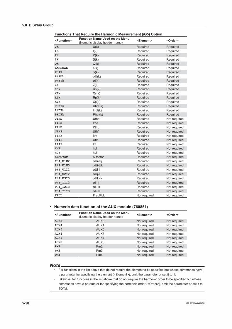
5-58 IM PX8000-17EN
Functions That Require the Harmonic Measurement (/G5) Option
<Function> Function Name Used on the Menu(Numeric display header name) <Element> <Order>
UK U(k) Required RequiredIK I(k) Required RequiredPK P(k) Required RequiredSK S(k) Required RequiredQK Q(k) Required RequiredLAMBDAK λ(k) Required RequiredPHIK φ(k) Required RequiredPHIUk φU(k) Required RequiredPHIIk φI(k) Required RequiredZk Z(k) Required RequiredRSk Rs(k) Required RequiredXSk Xs(k) Required RequiredRPk Rp(k) Required RequiredXPk Xp(k) Required RequiredUHDFk Uhdf(k) Required RequiredIHDFk Ihdf(k) Required RequiredPHDFk Phdf(k) Required RequiredUTHD Uthd Required Not requiredITHD Ithd Required Not requiredPTHD Pthd Required Not requiredUTHF Uthf Required Not requiredITHF Ithf Required Not requiredUTIF Utif Required Not requiredITIF Itif Required Not requiredHVF hvf Required Not requiredHCF hcf Required Not requiredKFACtor K-factor Required Not requiredPHI_U1U2 φUi-Uj Required Not requiredPHI_U1U3 φUi-Uk Required Not requiredPHI_U1I1 φUi-Ii Required Not requiredPHI_U2I2 φUj-Ij Required Not requiredPHI_U3I3 φUk-Ik Required Not requiredPHI_I1I2 φIi-Ij Required Not requiredPHI_I2I3 φIj-Ik Required Not requiredPHI_I1I3 φIi-Ik Required Not requiredFPLL FreqPLL Not required Not required
• Numeric data function of the AUX module (760851)
<Function> Function Name Used on the Menu(Numeric display header name) <Element> <Order>
AUX3 AUX3 Not required Not requiredAUX4 AUX4 Not required Not requiredAUX5 AUX5 Not required Not requiredAUX6 AUX6 Not required Not requiredAUX7 AUX7 Not required Not requiredAUX8 AUX5 Not required Not requiredPM2 Pm2 Not required Not requiredPM3 Pm3 Not required Not requiredPM4 Pm4 Not required Not required
Note• For functions in the list above that do not require the element to be specified but whose commands have
a parameter for specifying the element (<Element>), omit the parameter or set it to 1.• Likewise, for functions in the list above that do not require the harmonic order to be specified but whose
commands have a parameter for specifying the harmonic order (<Order>), omit the parameter or set it to TOTal.
5.8 DISPlay Group
5-59IM PX8000-17EN
Com
mand
1
2
3
4
5
6
App
Index
5.9 FFT Group
The commands in this group deal with FFT analysis. You can make the same settings and queries that you can by using the FFT (SHIFT+MATH) keys on the front panel.
:FFT:WAVeform<x>:HORizontal?Function Queries all horizontal axis settings for FFT
analysis.Syntax FFT:WAVeform<x>:HORizontal?
<x> = 1, 2
:FFT:WAVeform<x>:HORizontal:CSPan?Function Queries all center and span settings for the
horizontal axis for FFT analysis.Syntax :FFT:WAVeform<x>:HORizontal:CSPan?
<x> = 1, 2
:FFT:WAVeform<x>:HORizontal:CSPan:CENTerFunction Sets or queries the center value of the horizontal
axis for FFT analysis.Syntax :FFT:WAVeform<x>:HORizontal:CSPan:CE
NTer {<Frequency>}
:FFT:WAVeform<x>:HORizontal:CSPan:CE
NTer?
<x> = 1, 2 <Frequ ency> = 0 Hz to (the sampling rate)/2 HzExample :FFT:WAVEFORM1:HORIZONTAL:CSPAN:CENT
ER 250.00000E+03
:FFT:WAVEFORM1:HORIZONTAL:CSPAN:CENT
ER?
-> :FFT:WAVEFORM1:HORIZONTAL:CSPAN:C
ENTER 250.00000E+03
:FFT:WAVeform<x>:HORizontal:CSPan:SPANFunction Sets or queries the span value of the horizontal
axis for FFT analysis.Syntax :FFT:WAVeform<x>:HORizontal:CSPan:SP
AN {<Frequency>}
:FFT:WAVeform<x>:HORizontal:CSPan:SP
AN?
<x> = 1, 2 <Fr equency>
= (the sampling rate)/(FFT Points) * 10 Hz to (the sampling rate)/2 Hz
Example :FFT:WAVEFORM1:HORIZONTAL:CSPAN:
SPAN 500.00000E+03
:FFT:WAVEFORM1:HORIZONTAL:CSPAN:SP
AN?
-> :FFT:WAVEFORM1:HORIZONTAL:CSPAN:S
PAN 500.00000E+03
:FFT?Function Queries all FFT settings.Syntax :FFT?
:FFT:POINtFunction Sets or queries the number of analysis source
points of the FFT windows.Syntax :FFT:POINt {<NRf>}
:FFT:POINt?
<NRf> = 1000, 2000, 5000, 10000, 20000, 50000, 100000
Example :FFT:POINT 1000
:FFT:POINT? -> :FFT:POINT 1000
Description The setting is the same for Window 1 and Window 2. (The settings are the same as with the number of FFT points of the Math group.)
:FFT:STARtFunction Sets or queries the analysis-source start point of
the FFT windows.Syntax :FFT:STARt {<NRf>}
:FFT:STARt?
<NRf> = –5 to 5Example :FFT:START -5
:FFT:START?
-> :FFT:START -5.000000000000
Description The setting is the same for Window 1 and Window 2. (The settings are the same as with the number of FFT points of the Math group.)
:FFT:WAVeform<x>?Function Queries all FFT window settings. <x> = 1, 2
:FFT:WAVeform<x>:HAXisFunction Sets or queries an FFT window’s horizontal-axis
display method.Syntax :FFT:WAVeform<x>:HAXis {LINear|LOG}
:FFT:WAVeform<x>:HAXis?
<x> = 1, 2Example :FFT:WAVEFORM1:HAXIS LOG
:FFT:WAVEFORM1:HAXIS?
-> :FFT:WAVEFORM1:HAXIS LOG
5-60 IM PX8000-17EN
:FFT:WAVeform<x>:HORizontal:LRIGht?Function Queries all the settings for the left and right ends
of the horizontal axis for FFT analysis.Syntax :FFT:WAVeform<x>:HORizontal:LRIGht?
<x> = 1, 2
:FFT:WAVeform<x>:HORizontal:LRIGht:RANGeFunction Sets or queries the range for the left and right
ends of the horizontal axis for FFT analysis.Syntax :FFT:WAVeform<x>:HORizontal:LRIGht:R
ANGe {<Frequency>,<Frequency>}
:FFT:WAVeform<x>:HORizontal:LRIGht:R
ANGe?
<x> = 1, 2 <Frequency> = 0 Hz to (the sampling rate)/2 HzExample :FFT:WAVEFORM1:HORIZONTAL:LRIGHT:RAN
GE 0.0000000E+00,500.00000E+03
:FFT:WAVEFORM1:HORIZONTAL:LRIGHT:RAN
GE?
-> :FFT:WAVEFORM1:HORIZONTAL:LRIGHT:
RANGE 0.0000000E+00,500.00000E+03
:FFT:WAVeform<x>:HORizontal:MODEFunction Sets or queries the FFT analysis horizontal axis
mode.Syntax :FFT:WAVeform<x>:HORizontal:
MODE {AUTO|CSPan|LRIGht}
:FFT:WAVeform<x>:HORizontal:MODE?
<x> = 1, 2Example :FFT:WAVEFORM1:HORIZONTAL:MODE AUTO
:FFT:WAVEFORM1:HORIZONTAL:MODE?
-> :FFT:WAVEFORM1:HORIZONTAL:
MODE AUTO
:FFT:WAVeform<x>:MODEFunction Sets or queries whether an FFT window is
displayed.Syntax :FFT:WAVeform<x>:MODE {<Boolean>}
:FFT:WAVeform<x>:MODE?
<x> = 1, 2Example :FFT:WAVEFORM1:MODE ON
:FFT:WAVEFORM1:MODE?
-> :FFT:WAVEFORM1:MODE 0
:FFT:WAVeform<x>:SOURce<x>Function Sets or queries an FFT window’s FFT source
channel.Syntax :FFT:WAVeform<x>:
SOURce<x> {MATH<x>|<NRf>|P<y>}
:FFT:WAVeform<x>:SOURce<x>?
<x> of WAVeform<x> = 1, 2 <x> of SOURce<x> = 1, 2 <x> of MATH<x> = 1 to 8 <NRf> = 1 to 8 <y> = 1 to 4Example :FFT:WAVEFORM1:SOURCE1 1
:FFT:WAVEFORM1:SOURCE1?
-> :FFT:WAVEFORM1:SOURCE1 1
Description This command returns "Math1" if no modules are installed.
:FFT:WAVeform<x>:STYPe (Sub TYPe)Function Sets or queries an FFT window’s analysis sub
type.Syntax :FFT:WAVeform<x>:
STYPe {REAL|IMAG|MAG|PHASe|LOGMag}
:FFT:WAVeform<x>:STYPe?
<x> = 1, 2Example :FFT:WAVEFORM1:STYPE LOGMAG
:FFT:WAVEFORM1:STYPE?
-> :FFT:WAVEFORM1:STYPE LOGMAG
:FFT:WAVeform<x>:TYPEFunction Sets or queries an FFT window’s analysis type.Syntax :FFT:WAVeform<x>:
TYPE {LS|PS|PSD|CS|TF|CH}
:FFT:WAVeform<x>:TYPE?
<x> = 1, 2Example :FFT:WAVEFORM1:TYPE PS
:FFT:WAVEFORM1:TYPE?
-> :FFT:WAVEFORM1:TYPE PS
:FFT:WAVeform<x>:UNITFunction Sets or queries a unit string that is attached to
FFT computation results.Syntax FFT:WAVeform<x>:UNIT {<String>}
FFT:WAVeform<x>:UNIT?
<x> = 1, 2 <String> = Up to 4 charactersExample :FFT:WAVEFORM1:UNIT "UU"
:FFT:WAVEFORM1:UNIT?
-> :FFT:WAVEFORM1:UNIT "UU"
Description In the default settings, the unit string is blank.
5.9 FFT Group
5-61IM PX8000-17EN
Com
mand
1
2
3
4
5
6
App
Index
:FFT:WAVeform<x>:VSCale?Function Queries all FFT vertical scale settings.Syntax :FFT:WAVeform<x>:VSCale?
<x> = 1, 2
:FFT:WAVeform<x>:VSCale:CENTerFunction Sets or queries the center value of an FFT
window’s vertical scale.Syntax :FFT:WAVeform<x>:VSCale:
CENTer {<NRf>}
:FFT:WAVeform<x>:VSCale:CENTer?
<x> = 1, 2 <NRf> = –1E+30 to 1E+30Example :FFT:WAVEFORM1:VSCALE:CENTER -40
:FFT:WAVEFORM1:VSCALE:CENTER?
-> :FFT:WAVEFORM1:VSCALE:
CENTER -40.0000E+00
:FFT:WAVeform<x>:VSCale:MODE (Vertical SCale MODE)Function Sets or queries an FFT window’s vertical scale
mode.Syntax :FFT:WAVeform<x>:VSCale:
MODE {AUTO|MANual}
:FFT:WAVeform<x>:VSCale:MODE?
Example :FFT:WAVEFORM1:VSCALE:MODE AUTO
:FFT:WAVEFORM1:VSCALE:MODE?
-> :FFT:WAVEFORM1:VSCALE:MODE AUTO
:FFT:WAVeform<x>:VSCale:SENSitivityFunction Sets or queries the sensitivity of an FFT window’s
vertical scale.Syntax :FFT:WAVeform<x>:VSCALe:
SENSitivity {<NRf>}
:FFT:WAVeform<x>:VSCALe:SENSitivity?
<x> = 1, 2 <NRf> = 0 to 1E+30Example :FFT:WAVEFORM1:VSCALE:
SENSITIVITY 20.0000E+00
:FFT:WAVEFORM1:VSCALE:SENSITIVITY?
-> :FFT:WAVEFORM1:VSCALE:
SENSITIVITY 20.0000E+00
:FFT:WINDow?Function Queries all FFT analysis settings.Syntax :FFT:WINDow?
:FFT:WINDow:EXPonential?Function Queries all FFT exponential window settings.Syntax :FFT:WINDow:EXPonential?
:FFT:WINDow:EXPonential:DRATeFunction Sets or queries the FFT exponential window’s
damping rate.Syntax :FFT:WINDow:EXPonential:
DRATe {<NRf>}
:FFT:WINDow:EXPonential:DRATe?
<NRf> = 1 to 100Example :FFT:WINDOW:EXPONENTIAL:DRATE 100
:FFT:WINDOW:EXPONENTIAL:DRATE?
-> :FFT:WINDOW:EXPONENTIAL:DRATE 100
Description The setting is the same for Window 1 and Window 2. (The settings are the same as with the number of FFT points of the Math group.)
:FFT:WINDow:EXPonential:FORCe<x>Function Sets or queries the FFT exponential window’s
Force1 or Force2 value.Syntax :FFT:WINDow:EXPonential:
FORCe<x> {<NRf>}
:FFT:WINDow:EXPonential:FORCe<x>?
<NRf> = 1 to 100Example :FFT:WINDOW:EXPONENTIAL:FORCE1 100
:FFT:WINDOW:EXPONENTIAL:FORCE1?
-> :FFT:WINDOW:EXPONENTIAL:
FORCE1 100
Description The setting is the same for Window 1 and Window 2. (The settings are the same as with the number of FFT points of the Math group.)
:FFT:WINDow:TYPEFunction Sets or queries the computation window type for
FFT analysis.Syntax :FFT:WINDow:TYPE {HANNing|RECTangle|
FLATtop|EXPonential|HAMMing}
:FFT:WINDow:TYPE?
Example :FFT:WINDOW:TYPE HANNING
:FFT:WINDOW:TYPE?
-> :FFT:WINDOW:TYPE HANNING
Description The setting is the same for Window 1 and Window 2. (The settings are the same as with the number of FFT points of the Math group.)
5.9 FFT Group
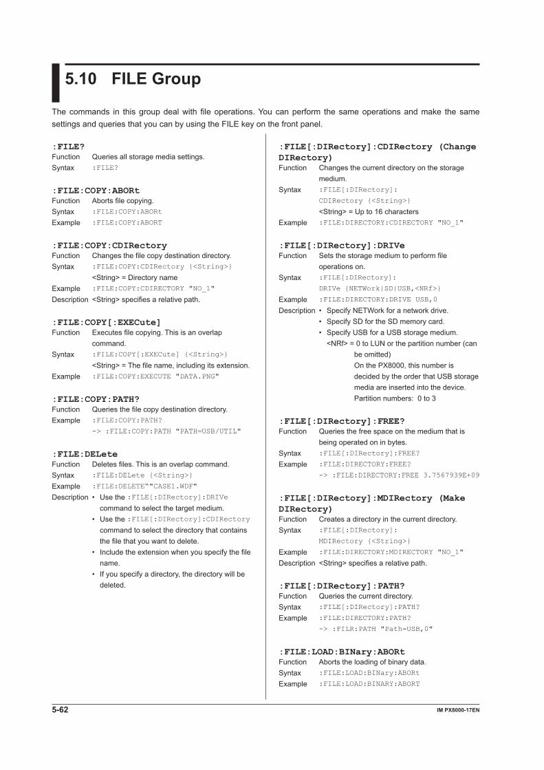
5-62 IM PX8000-17EN
5.10 FILE Group
The commands in this group deal with file operations. You can perform the same operations and make the same settings and queries that you can by using the FILE key on the front panel.
:FILE[:DIRectory]:CDIRectory (Change DIRectory)Function Changes the current directory on the storage
medium.Syntax :FILE[:DIRectory]:
CDIRectory {<String>}
<String> = Up to 16 charactersExample :FILE:DIRECTORY:CDIRECTORY "NO_1"
:FILE[:DIRectory]:DRIVeFunction Sets the storage medium to perform file
operations on.Syntax :FILE[:DIRectory]:
DRIVe {NETWork|SD|USB,<NRf>}
Example :FILE:DIRECTORY:DRIVE USB,0
Description • Specify NETWork for a network drive. • Specify SD for the SD memory card. • Specify USB for a USB storage medium. <NRf> = 0 to LUN or the partition number (can
be omitted) On the PX8000, this number is decided by the order that USB storage media are inserted into the device. Partition numbers: 0 to 3
:FILE[:DIRectory]:FREE?Function Queries the free space on the medium that is
being operated on in bytes.Syntax :FILE[:DIRectory]:FREE?
Example :FILE:DIRECTORY:FREE?
-> :FILE:DIRECTORY:FREE 3.7567939E+09
:FILE[:DIRectory]:MDIRectory (Make DIRectory)Function Creates a directory in the current directory.Syntax :FILE[:DIRectory]:
MDIRectory {<String>}
Example :FILE:DIRECTORY:MDIRECTORY "NO_1"
Description <String> specifies a relative path.
:FILE[:DIRectory]:PATH?Function Queries the current directory.Syntax :FILE[:DIRectory]:PATH?
Example :FILE:DIRECTORY:PATH?
-> :FILR:PATH "Path=USB,0"
:FILE:LOAD:BINary:ABORtFunction Aborts the loading of binary data.Syntax :FILE:LOAD:BINary:ABORt
Example :FILE:LOAD:BINARY:ABORT
:FILE?Function Queries all storage media settings.Syntax :FILE?
:FILE:COPY:ABORtFunction Aborts file copying.Syntax :FILE:COPY:ABORt
Example :FILE:COPY:ABORT
:FILE:COPY:CDIRectoryFunction Changes the file copy destination directory.Syntax :FILE:COPY:CDIRectory {<String>}
<String> = Directory nameExample :FILE:COPY:CDIRECTORY "NO_1"
Description <String> specifies a relative path.
:FILE:COPY[:EXECute]Function Executes file copying. This is an overlap
command.Syntax :FILE:COPY[:EXECute] {<String>}
<String> = The file name, including its extension.Example :FILE:COPY:EXECUTE "DATA.PNG"
:FILE:COPY:PATH?Function Queries the file copy destination directory.Example :FILE:COPY:PATH?
-> :FILE:COPY:PATH "PATH=USB/UTIL"
:FILE:DELeteFunction Deletes files. This is an overlap command.Syntax :FILE:DELete {<String>}
Example :FILE:DELETE“"CASE1.WDF"
Description • Use the :FILE[:DIRectory]:DRIVe command to select the target medium.
• Use the :FILE[:DIRectory]:CDIRectory command to select the directory that contains the file that you want to delete.
• Include the extension when you specify the file name.
• If you specify a directory, the directory will be deleted.
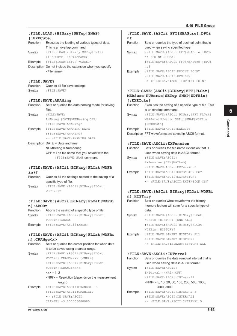
5-63IM PX8000-17EN
Com
mand
1
2
3
4
5
6
App
Index
:FILE:LOAD:{BINary|SETup|SNAP}[:EXECute]Function Executes the loading of various types of data.
This is an overlap command.Syntax :FILE:LOAD:{BINary|SETup|SNAP}
[:EXECute] {<Filename>}
Example :FILE:LOAD:SETUP "CASE1"
Description Do not include the extension when you specify <Filename>.
:FILE:SAVE?Function Queries all file save settings.Syntax :FILE:SAVE?
:FILE:SAVE:ANAMingFunction Sets or queries the auto naming mode for saving
files.Syntax :FILE:SAVE:
ANAMing {DATE|NUMBering|OFF}
:FILE:SAVE:ANAMing?
Example :FILE:SAVE:ANAMING DATE
:FILE:SAVE:ANAMING?
-> :FILE:SAVE:ANAMING DATE
Description DATE = Date and time NUMBering = Numbering OFF = The file name that you saved with the
:FILE:SAVE:NAME command
:FILE:SAVE:{ASCii|BINary|FLOat|WDFBin}?Function Queries all the settings related to the saving of a
specific type of file.Syntax :FILE:SAVE:{ASCii|BINary|FLOat|
WDFBin}?
:FILE:SAVE:{ASCii|BINary|FLOat|WDFBin}:ABORtFunction Aborts the saving of a specific type of file.Syntax :FILE:SAVE:{ASCii|BINary|FLOat|
WDFBin}:ABORt
Example :FILE:SAVE:ASCii:ABORT
:FILE:SAVE:{ASCii|BINary|FLOat|WDFBin}:CRANge<x>Function Sets or queries the cursor position for when data
is to be saved using a cursor range.Syntax :FILE:SAVE:{ASCii|BINary|FLOat|
WDFBin}:CRANGe<x> {<NRf>}
:FILE:SAVE:{ASCii|BINary|FLOat|
WDFBin}:CRANGe<x>?
<x> = 1, 2 <NRf> = Resolution (depends on the measurement
length)Example :FILE:SAVE:ASCII:CRANGE1 -3
:FILE:SAVE:ASCII:CRANGE1?
-> :FILE:SAVE:ASCII:
CRANGE1 -3.000000000000
:FILE:SAVE:{ASCii|FFT|MEASure}:DPOintFunction Sets or queries the type of decimal point that is
used when saving specified type.Syntax :FILE:SAVE:{ASCii|FFT|MEASure}:DPOi
nt {POINt|COMMa}
:FILE:SAVE:{ASCii|FFT|MEASure}:DPOi
nt?
Example :FILE:SAVE:ASCII:DPOINT POINT
:FILE:SAVE:ASCII:DPOINT?
-> :FILE:SAVE:ASCII:DPOINT POINT
:FILE:SAVE:{ASCii|BINary|FFT|FLOat|MEASure|NUMeric|SETup|SNAP|WDFBin}[:EXECute]Function Executes the saving of a specific type of file. This
is an overlap command.Syntax :FILE:SAVE:{ASCii|BINary|FFT|FLOat|
MEASure|NUMeric|SETup|SNAP|WDFBin}
[:EXECute]
Example :FILE:SAVE:ASCII:EXECUTE
Description FFT waveforms are saved in ASCII format.
:FILE:SAVE:ASCii:EXTensionFunction Sets or queries the file name extension that is
used when saving data in ASCII format.Syntax :FILE:SAVE:ASCii:
EXTension {CSV|MATLab}
:FILE:SAVE:ASCii:EXTension?
Example :FILE:SAVE:ASCII:EXTENSION CSV
:FILE:SAVE:ASCII:EXTENSION?
-> :FILE:SAVE:ASCII:EXTENSION CSV
:FILE:SAVE:{ASCii|BINary|FLOat|WDFBin}:HISToryFunction Sets or queries what waveforms the history
memory feature will save for a specific type of data.
Syntax :FILE:SAVE:{ASCii|BINary|FLOat|
WDFBin}:HISTORY {ONE|ALL}
:FILE:SAVE:{ASCii|BINary|FLOat|
WDFBin}:HISTORY?
Example :FILE:SAVE:BINARY:HISTORY ALL
:FILE:SAVE:BINARY:HISTORY?
-> :FILE:SAVE:BINARY:HISTORY ALL
:FILE:SAVE:ASCii:INTervalFunction Sets or queries the data removal interval that is
used when saving data in ASCII format.Syntax :FILE:SAVE:ASCii:
INTerval {<NRf>|OFF}
:FILE:SAVE:ASCii:INTerval?
<NRf> = 5, 10, 20, 50, 100, 200, 500, 1000, 2000, 5000
Example :FILE:SAVE:ASCII:INTERVAL 5
:FILE:SAVE:ASCII:INTERVAL?
-> :FILE:SAVE:ASCII:INTERVAL 5
5.10 FILE Group
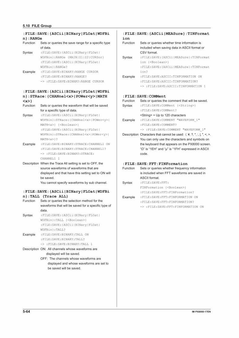
5-64 IM PX8000-17EN
:FILE:SAVE:{ASCii|BINary|FLOat|WDFBin}:RANGeFunction Sets or queries the save range for a specific type
of data.Syntax :FILE:SAVE:{ASCii|BINary|FLOat|
WDFBin}:RANGe {MAIN|Z1|Z2|CURSor}
:FILE:SAVE:{ASCii|BINary|FLOat|
WDFBin}:RANGe?
Example :FILE:SAVE:BINARY:RANGE CURSOR
:FILE:SAVE:BINARY:RANGE?
-> :FILE:SAVE:BINARY:RANGE CURSOR
:FILE:SAVE:{ASCii|BINary|FLOat|WDFBin}:STRace:{CHANnel<x>|POWer<y>|MATH<x>}Function Sets or queries the waveform that will be saved
for a specific type of data.Syntax :FILE:SAVE:{ASCii|BINary|FLOat|
WDFBin}:STRace:{CHANnel<x>|POWer<y>|
MATH<x>} {<Boolean>}
:FILE:SAVE:{ASCii|BINary|FLOat|
WDFBin}:STRace:{CHANnel<x>|POWer<y>|
MATH<x>}?
Example :FILE:SAVE:BINARY:STRACE:CHANNEL1 ON
:FILE:SAVE:BINARY:STRACE:CHANNEL1?
-> :FILE:SAVE:BINARY:STRACE:
CHANNEL1 1
Description When the Trace All setting is set to OFF, the source waveforms of waveforms that are displayed and that have this setting set to ON will be saved.
You cannot specify waveforms by sub channel.
:FILE:SAVE:{ASCii|BINary|FLOat|WDFBin}:TALL (Trace ALL)Function Sets or queries the selection method for the
waveforms that will be saved for a specific type of data.
Syntax :FILE:SAVE:{ASCii|BINary|FLOat|
WDFBin}:TALL {<Boolean>}
:FILE:SAVE:{ASCii|BINary|FLOat|
WDFBin}:TALL?
Example :FILE:SAVE:BINARY:TALL ON
:FILE:SAVE:BINARY:TALL?
-> :FILE:SAVE:BINARY:TALL 1
Description ON: All channels whose waveforms are displayed will be saved.
OFF: The channels whose waveforms are displayed and whose waveforms are set to be saved will be saved.
:FILE:SAVE:{ASCii|MEASure}:TINFormationFunction Sets or queries whether time information is
included when saving data in ASCII format or CSV format.
Syntax :FILE:SAVE:{ASCii|MEASure}:TINFormat
ion {<Boolean>}
:FILE:SAVE:{ASCii|MEASure}:TINFormat
ion?
Example :FILE:SAVE:ASCII:TINFORMATION ON
:FILE:SAVE:ASCII:TINFORMATION?
-> :FILE:SAVE:ASCII:TINFORMATION 1
:FILE:SAVE:COMMentFunction Sets or queries the comment that will be saved.Syntax :FILE:SAVE:COMMent {<String>}
:FILE:SAVE:COMMent?
<String> = Up to 120 charactersExample :FILE:SAVE:COMMENT "WAVEFORM_1"
:FILE:SAVE:COMMENT?
-> :FILE:SAVE:COMMENT "WAVEFORM_1"
Description Characters that cannot be used: /, ¥, ?, *, :, |, ", <, >. You can only use the characters and symbols on
the keyboard that appears on the PX8000 screen. “Ω”is“1EH”and“μ”is“1FH”expressedinASCIIcode.
:FILE:SAVE:FFT:FINFormationFunction Sets or queries whether frequency information
is included when FFT waveforms are saved in ASCII format.
Syntax :FILE:SAVE:FFT:
FINFormation {<Boolean>}
:FILE:SAVE:FFT:FINFormation?
Example :FILE:SAVE:FFT:FINFORMATION ON
:FILE:SAVE:FFT:FINFORMATION?
-> :FILE:SAVE:FFT:FINFORMATION ON
5.10 FILE Group
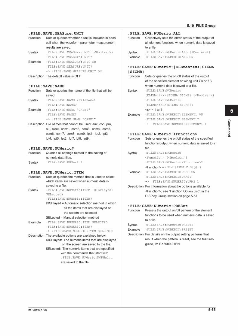
5-65IM PX8000-17EN
Com
mand
1
2
3
4
5
6
App
Index
:FILE:SAVE:MEASure:UNITFunction Sets or queries whether a unit is included in each
cell when the waveform parameter measurement results are saved.
Syntax :FILE:SAVE:MEASure:UNIT {<Boolean>}
:FILE:SAVE:MEASure:UNIT?
Example :FILE:SAVE:MEASURE:UNIT ON
:FILE:SAVE:MEASURE:UNIT?
-> :FILE:SAVE:MEASURE:UNIT ON
Description The default value is OFF.
:FILE:SAVE:NAMEFunction Sets or queries the name of the file that will be
saved.Syntax :FILE:SAVE:NAME <Filename>
:FILE:SAVE:NAME?
Example :FILE:SAVE:NAME "CASE1"
:FILE:SAVE:NAME?
-> :FILE:SAVE:NAME "CASE1"
Description File names that cannot be used: aux, con, prn, nul, clock, com1, com2, com3, com4, com5, com6, com7, com8, com9, lpt1, lpt2, lpt3, lpt4, lpt5, lpt6, lpt7, lpt8, lpt9.
:FILE:SAVE:NUMeric?Function Queries all settings related to the saving of
numeric data files.Syntax :FILE:SAVE:NUMeric?
:FILE:SAVE:NUMeric:ITEMFunction Sets or queries the method that is used to select
which items are saved when numeric data is saved to a file.
Syntax :FILE:SAVE:NUMeric:ITEM {DISPlayed| SELected}
:FILE:SAVE:NUMeric:ITEM?
DISPlayed = Automatic selection method in which all the items that are displayed on the screen are selected
SELected = Manual selection methodExample :FILE:SAVE:NUMERIC:ITEM SELECTED :FILE:SAVE:NUMERIC:ITEM?
-> :FILE:SAVE:NUMERIC:ITEM SELECTED
Description The available options are explained below. DISPlayed: The numeric items that are displayed
on the screen are saved to the file. SELected: The numeric items that are specified
with the commands that start with :FILE:SAVE:NUMeric:NORMal:… are saved to the file.
:FILE:SAVE:NUMeric:ALLFunction Collectively sets the on/off status of the output of
all element functions when numeric data is saved to a file.
Syntax :FILE:SAVE:NUMeric:ALL {<Boolean>}
Example :FILE:SAVE:NUMERIC:ALL ON
:FILE:SAVE:NUMeric:{ELEMent<x>|SIGMA|SIGMB}Function Sets or queries the on/off status of the output
ofthespecifiedelementorwiringunitΣAorΣBwhen numeric data is saved to a file.
Syntax :FILE:SAVE:NUMeric:
{ELEMent<x>|SIGMA|SIGMB} {<Boolean>}
:FILE:SAVE:NUMeric:
{ELEMent<x>|SIGMA|SIGMB}?
<x> = 1 to 4Example :FILE:SAVE:NUMERIC:ELEMENT1 ON
:FILE:SAVE:NUMERIC:ELEMENT1?
-> :FILE:SAVE:NUMERIC:ELEMENT1 1
:FILE:SAVE:NUMeric:<Function>Function Sets or queries the on/off status of the specified
function’s output when numeric data is saved to a file.
Syntax :FILE:SAVE:NUMeric:
<Function> {<Boolean>}
:FILE:SAVE:NUMeric:<Function>?
<Function> = {URMS|IRMS|P|S|Q|…}Example :FILE:SAVE:NUMERIC:URMS ON
:FILE:SAVE:NUMERIC:URMS?
-> :FILE:SAVE:NUMERIC:URMS 1
Description For information about the options available for <Function>, see “Function Option List”, in the DISPlay Group section on page 5-57.
:FILE:SAVE:NUMeric:PRESetFunction Presets the output on/off pattern of the element
functions to be used when numeric data is saved to a file.
Syntax :FILE:SAVE:NUMeric:PRESet
Example :FILE:SAVE:NUMERIC:PRESET
Description For details on the output setting patterns that result when the pattern is reset, see the features guide, IM PX8000-01EN.
5.10 FILE Group
5-66 IM PX8000-17EN
5.11 GONogo Group
The commands in this group deal with GO/NO-GO determination. You can make the same settings and queries (of settings and measured values) that you can by using the GO/NO-GO (SHIFT+MEASURE) keys on the front panel.If the selectable range of the time axis is “<NRf> = –5 to 5div,” the selectable range varies depending on settings such as the record length. For details, see “Notes about Cursor Measurement” in chapter 15 of IM PX8000-01EN.
:GONogo:ACTion:IMAGe?Function Queries all settings for the screen capture that is
saved when the condition is met.Syntax :GONogo:ACTion:IMAGe?
:GONogo:ACTion:IMAGe:CDIRectoryFunction Sets the current directory where the screen
capture is saved to when the condition is met.Syntax :GONogo:ACTion:IMAGe:
CDIRectory {<String>}
:GONogo:ACTion:IMAGe:CDIRectory?
<String> = Directory nameExample :GONOGO:ACTION:IMAGE:
CDIRECTORY "CASE1"
:GONOGO:ACTION:IMAGE:CDIRECTORY?
-> :GONOGO:ACTION:IMAGE:
CDIRECTORY "CASE1"
:GONogo:ACTion:IMAGe:DRIVeFunction Sets or queries the medium that the screen
capture is saved to when the condition is met.Syntax :GONogo:ACTion:IMAGe:
DRIVe {NETWork|SD|USB,<NRf>}
:GONogo:ACTion:IMAGe:DRIVe?
Example :GONOGO:ACTION:IMAGE:DRIVE USB,0
:GONOGO:ACTION:IMAGE:DRIVE?
-> :GONOGO:ACTION:IMAGE:DRIVE USB,0
Description • Specify NETWork for a network drive. • Specify SD for the SD memory card. • Specify USB for a USB storage medium. <NRf> = 0 to LUN or the partition number (can
be omitted) On the PX8000, this number is decided by the order that USB storage media are inserted into the device. Partition numbers: 0 to 3
:GONogo:ACTion:IMAGe[:MODE]Function Sets or queries whether a screen capture is
saved when the condition is met.Syntax :GONogo:ACTion:
IMAGe[:MODE] {<Boolean>}
:GONogo:ACTion:IMAGe:MODE?
Example :GONOGO:ACTION:IMAGE:MODE ON
:GONOGO:ACTION:IMAGE:MODE?
-> :GONOGO:ACTION:IMAGE:MODE 1
:GONogo?Function Queries all GO/NO-GO determination settings.Syntax :GONogo?
:GONogo:ACONditionFunction Sets or queries the GO/NO-GO determination-
action condition.Syntax :GONogo:ACONdition {ALWays|FAILure|
SUCCess}
:GONogo:ACONdition?
Example :GONOGO:ACONDITION ALWAYS
:GONOGO:ACONDITION?
-> :GONOGO:ACONDITION ALWAYS
:GONogo:ACTion?Function Queries all settings for the action that is
performed when the condition is met and the settings for the condition itself.
Syntax :GONogo:ACTion?
:GONogo:ACTion:BUZZerFunction Sets or queries whether a beep is sounded when
the condition is met.Syntax :GONogo:ACTion:BUZZer {<Boolean>}
:GONogo:ACTion:BUZZer?
Example :GONOGO:ACTION:BUZZER ON
:GONOGO:ACTION:BUZZER?
-> :GONOGO:ACTION:BUZZER 1
:GONogo:ACTion:HCOPy (HardCOPy)Function Sets or queries whether a screen capture is
printed from the built-in printer when the condition is met.
Syntax :GONogo:ACTion:HCOPy {<Boolean>}
:GONogo:ACTion:HCOPy?
Example :GONOGO:ACTION:HCOPY ON
:GONOGO:ACTION:HCOPY?
-> :GONOGO:ACTION:HCOPY 1
Description This command is valid only when the built-in printer (/B5 option) is installed.
5-67IM PX8000-17EN
Com
mand
1
2
3
4
5
6
App
Index
:GONogo:ACTion:IMAGe:PATH?Function Queries the path on the storage medium that a
screen capture is saved to when the condition is met.
Syntax :GONogo:ACTion:IMAGe:PATH?
Example :GONOGO:ACTION:IMAGE:PATH?
-> :GONOGO:ACTION:IMAGE:
PATH "Path=SD"
:GONogo:ACTion:SAVE?Function Queries all settings related to the storage
medium that waveform data is saved to when the condition is met.
Syntax :GONogo:ACTion:SAVE?
:GONogo:ACTion:SAVE:CDIRectoryFunction Sets the current directory on the storage medium
where waveform data is saved to when the condition is met.
Syntax :GONogo:ACTion:SAVE:
CDIRectory {<String>}
:GONogo:ACTion:SAVE:CDIRectory?
Example :GONOGO:ACTION:SAVE:
CDIRECTORY "CASE1"
:GONOGO:ACTION:SAVE:CDIRECTORY?
-> :GONOGO:ACTION:SAVE:
CDIRECTORY "CASE1"
:GONogo:ACTion:SAVE:DRIVeFunction Sets or queries the storage medium that
waveform data is saved to when the condition is met.
Syntax :GONogo:ACTion:SAVE:
DRIVe {NETWork|SD|USB,<NRf>}
:GONogo:ACTion:SAVE:DRIVe?
Example :GONOGO:ACTION:SAVE:DRIVE USB,0
:GONOGO:ACTION:SAVE:DRIVE?
-> :GONOGO:ACTION:SAVE:DRIVE USB,0
Description • Specify NETWork for a network drive. • Specify SD for the SD memory card. • Specify USB for a USB storage medium. <NRf> = 0 to LUN or the partition number (can
be omitted) On the PX8000, this number is decided by the order that USB storage media are inserted into the device. Partition numbers: 0 to 3
:GONogo:ACTion:SAVE[:MODE]Function Sets or queries whether waveforms are saved to
the storage medium when the condition is met.Syntax :GONogo:ACTion:SAVE:MODE {<Boolean>}
:GONogo:ACTion:SAVE:MODE?
Example :GONOGO:ACTION:SAVE:MODE ON
:GONOGO:ACTION:SAVE:MODE?
-> :GONOGO:ACTION:SAVE:MODE 1
:GONogo:ACTion:SAVE:PATH?Function Queries the path on the storage medium that
waveform data is saved to when the condition is met.
Syntax :GONogo:ACTion:SAVE:PATH?
Example :GONOGO:ACTION:SAVE:PATH?
-> :GONOGO:ACTION:SAVE:
PATH "Path=USB,0/WAVE"
:GONogo:ACTion:SAVE:TYPEFunction Sets or queries the file format that waveforms
are saved as on the storage medium when the condition is met.
Syntax :GONogo:ACTion:SAVE:
TYPE {ASCii|BINary|FLOat|WDFBin}
:GONogo:ACTion:SAVE:TYPE?
Example :GONOGO:ACTION:SAVE:TYPE BINARY
:GONOGO:ACTION:SAVE:TYPE?
-> :GONOGO:ACTION:SAVE:TYPE BINARY
:GONogo:COUNt?Function Queries the number of GO/NO-GO
determinations that were performed.Syntax :GONogo:COUNt?
Example :GONOGO:COUNT? -> :GONOGO:COUNT 10
:GONogo:LOGicFunction Sets or queries the GO/NO-GO determination
logic.Syntax :GONogo:LOGic {AND|OR}
:GONogo:LOGic?
Example :GONOGO:LOGIC AND
:GONOGO:LOGIC? -> :GONOGO:LOGIC AND
:GONogo:MODEFunction Sets or queries the GO/NO-GO determination
mode.Syntax :GONogo:MODE {OFF|PARameter|ZONE}
:GONogo:MODE?
Example :GONOGO:MODE ZONE
:GONOGO:MODE? -> :GONOGO:MODE ZONE
:GONogo:NGCount?Function Queries the GO/NO-GO determination NO-GO
count.Syntax :GONogo:NGCount?
Example :GONOGO:NGCOUNT?
-> :GONOGO:NGCOUNT 10
5.11 GONogo Group
5-68 IM PX8000-17EN
:GONogo:PARameter?Function Queries all parameter determination settings.Syntax :GONogo:PARameter?
:GONogo:PARameter:ITEM<x>?Function Queries all settings for the specified waveform
parameter for parameter determination.Syntax :GONogo:PARameter:ITEM<x>?
<x> = 1 to 16
:GONogo:PARameter:ITEM<x>:CAUSe?Function Queries whether the specified waveform
parameter for parameter determination is the cause of a NO-GO judgment.
Syntax :GONogo:PARameter:ITEM<x>:CAUSe?
<x> = 1 to 16Example :GONOGO:PARAMETER:ITEM1:CAUSE?
-> :GONOGO:PARAMETER:ITEM1:CAUSE 1
Description When the parameter is the cause of a NO-GO result, the PX8000 returns 1. Otherwise, the PX8000 returns 0.
:GONogo:PARameter:ITEM<x>:MODEFunction Sets or queries the specified waveform
parameter’s reference condition for parameter determination.
Syntax :GONogo:PARameter:ITEM<x>:
MODE {OFF|IN|OUT}
:GONogo:PARameter:ITEM<x>:MODE?
<x> = 1 to 16Example :GONOGO:PARAMETER:ITEM1:MODE IN
:GONOGO:PARAMETER:ITEM1:MODE?
-> :GONOGO:PARAMETER:ITEM1:MODE IN
:GONogo:PARameter:ITEM<x>:TRACeFunction Sets or queries the specified waveform
parameter’s source waveform for parameter determination.
Syntax :GONogo:PARameter:ITEM<x>:
TRACe {<NRf>|P<y>|MATH<x>}
:GONogo:PARameter:ITEM<x>:TRACe?
<x> = 1 to 16 <NRf> = 1 to 8 <x> of MATH<x> = 1 to 8 <y> = 1 to 4Example :GONOGO:PARAMETER:ITEM1:TRACE 1
:GONOGO:PARAMETER:ITEM1:TRACE?
-> :GONOGO:PARAMETER:ITEM1:TRACE 1
:GONogo:PARameter:ITEM<x>:TYPE?Function Queries, for parameter determination, the
specified waveform parameter’s measurement item and upper and lower limits.
Syntax :GONogo:PARameter:ITEM<x>:TYPE?
<x> = 1 to 16Example :GONOGO:PARAMETER:ITEM1:TYPE?
-> :GONOGO:PARAMETER:ITEM1:TYPE:
MAXIMUM 1.10000E+00,1.00000E+00
:GONogo:PARameter:ITEM<x>:TYPE:<Parameter>Function Sets or queries the upper and lower limits of the
measurement item for the specified waveform parameter.
Syntax :GONogo:PARameter:ITEM<x>:TYPE:
<Parameter> {<Voltage>,<Voltage>|
<Current>,<Current>|<Time>,<Time>|
<Frequency>,<Frequency>|<NRf>,<NRf>}
<x> = 1 to 16 <Parameter> = {AMPLitude|AVERage|
AVGFreq|AVGPeriod|
BWIDth1|BWIDth2|
DELay|DUTYcycle|FALL|
FREQuency|HIGH|LOW|
MAXimum|MIDDle|MINimum|
NOVershoot|NWIDth|
PERiod|PNUMber|
POVershoot|PTOPeak|
PWIDth|RISE|RMS|
SDEViation|TY1Integ|
TY2Integ}
:GONogo:PARameter:ITEM<x>:VALue?Function Queries the measured value of the specified
waveform parameter.Syntax :GONogo:PARameter:ITEM<x>:VALue?
<x> = 1 to 16
:GONogo:REMoteFunction Sets or queries the remote mode of GO/NO-GO
determination.Syntax :GONogo:REMote {<Boolean>}
:GONogo:REMote?
Example :GONOGO:REMOTE ON
:GONOGO:REMOTE? -> :GONOGO:REMOTE 1
:GONogo:SEQuenceFunction Sets or queries the action mode of GO/NO-GO
determination.Syntax :GONogo:SEQuence {CONTinue|SINGle}
:GONogo:SEQuence?
Example :GONOGO:SEQUENCE CONTINUE
:GONOGO:SEQUENCE?
-> :GONOGO:SEQUENCE CONTINUE
5.11 GONogo Group
5-69IM PX8000-17EN
Com
mand
1
2
3
4
5
6
App
Index
:GONogo:TRANgeFunction Sets or queries the determination range of GO/
NO-GO determination.Syntax :GONogo:TRANge {<NRf>,<NRf>}
:GONogo:TRANge?
<NRf> = –5 to 5 divExample :GONOGO:TRANGE -5, 5
:GONOGO:TRANGE?
-> :GONOGO:TRANGE -5.000000000000,
5.000000000000
:GONogo:WAIT?Function Waits for the completion of GO/NO-GO
determination by using a timeout value.Syntax :GONogo:WAIT? {<NRf>}
<NRf> = 1 to 864000 (in units of 100 ms)Example Setting the timeout value to 5 seconds :GONOGO:WAIT? 50 -> 0
Description The PX8000 returns 0 if the operation finishes before the timer expires and returns 1 if the timer expires.
:GONogo:ZONE?Function Queries all waveform zone determination
settings.Syntax :GONogo:ZONE?
:GONogo:ZONE:PATTern<x>?Function Queries all settings for the specified determination
pattern for waveform zone determination.Syntax :GONogo:ZONE:PATTern<x>?
:GONogo:ZONE:PATTern<x>:CAUSe?Function Queries whether the specified determination
pattern for waveform zone determination is the cause of a NO-GO judgment.
Syntax :GONogo:ZONE:PATTern<x>:CAUSe?
<x> = 1 to 16Example :GONOGO:ZONE:PATTERN1 CAUSE?
-> :GONOGO:ZONE:PATTERN1 CAUSE 0
Description When the determination pattern is the cause of a NO-GO result, the PX8000 returns 1. Otherwise, the PX8000 returns 0.
:GONogo:ZONE:PATTern<x>:MODEFunction Sets or queries the specified determination
pattern’s reference condition for waveform zone determination.
Syntax :GONogo:ZONE:PATTern<x>:MODE {IN|
OUT|OFF}
:GONogo:ZONE:PATTern<x>:MODE?
<x> = 1 to 16Example :GONOGO:ZONE:PATTERN1:MODE IN
:GONOGO:ZONE:PATTERN1:MODE?
-> :GONOGO:ZONE:PATTERN1:MODE IN
:GONogo:ZONE:PATTern<x>:TRACeFunction Sets or queries the specified determination
pattern’s determination waveform for waveform zone determination.
Syntax :GONogo:ZONE:PATTern<x>:
TRACe {MATH<x>|<NRf>|P<y>}
:GONogo:ZONE:PATTern<x>:TRACe?
<x> = 1 to 16 <x> of MATH<x> = 1 to 8 <NRf> = 1 to 8 <y> = 1 to 4Example :GONOGO:ZONE:PATTERN1:TRACE 1
:GONOGO:ZONE:PATTERN1:TRACE?
-> :GONOGO:ZONE:PATTERN1:TRACE 1
:GONogo:ZONE:PATTern<x>:ZONEFunction Sets or queries the specified determination
pattern’s source waveform zone data for waveform zone determination.
Syntax :GONogo:ZONE:PATTern<x>:ZONE {<NRf>}
:GONogo:ZONE:PATTern<x>:ZONE?
<x> = 1 to 16 <NRf> = 0 to 5Example :GONOGO:ZONE:PATTERN1:ZONE 1
:GONOGO:ZONE:PATTERN1:ZONE?
-> :GONOGO:ZONE:PATTERN1:ZONE 1
5.11 GONogo Group
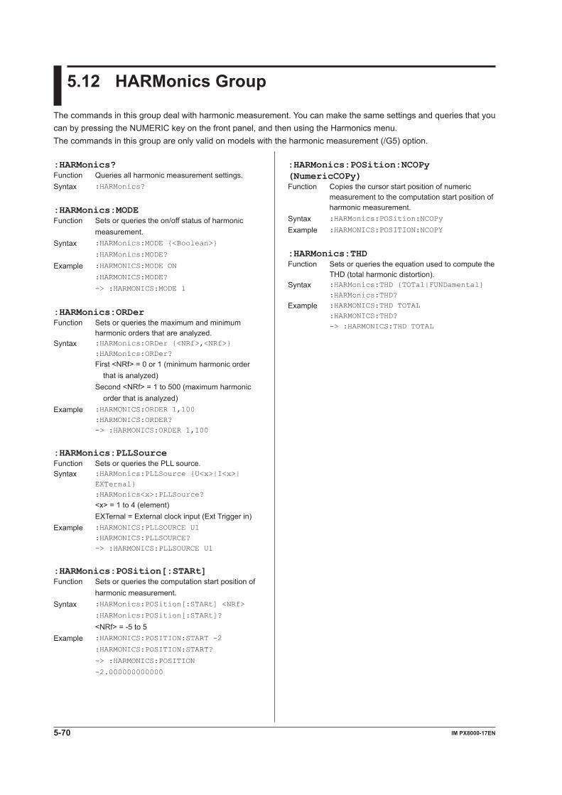
5-70 IM PX8000-17EN
5.12 HARMonics Group
The commands in this group deal with harmonic measurement. You can make the same settings and queries that you can by pressing the NUMERIC key on the front panel, and then using the Harmonics menu.The commands in this group are only valid on models with the harmonic measurement (/G5) option.
:HARMonics?Function Queries all harmonic measurement settings.Syntax :HARMonics?
:HARMonics:MODEFunction Sets or queries the on/off status of harmonic
measurement.Syntax :HARMonics:MODE {<Boolean>}
:HARMonics:MODE?
Example :HARMONICS:MODE ON
:HARMONICS:MODE?
-> :HARMONICS:MODE 1
:HARMonics:ORDerFunction Sets or queries the maximum and minimum
harmonic orders that are analyzed.Syntax :HARMonics:ORDer {<NRf>,<NRf>} :HARMonics:ORDer?
First <NRf> = 0 or 1 (minimum harmonic order that is analyzed)
Second <NRf> = 1 to 500 (maximum harmonic order that is analyzed)
Example :HARMONICS:ORDER 1,100 :HARMONICS:ORDER?
-> :HARMONICS:ORDER 1,100
:HARMonics:PLLSourceFunction Sets or queries the PLL source.Syntax :HARMonics:PLLSource {U<x>|I<x>|
EXTernal} :HARMonics<x>:PLLSource?
<x> = 1 to 4 (element) EXTernal = External clock input (Ext Trigger in)Example :HARMONICS:PLLSOURCE U1 :HARMONICS:PLLSOURCE?
-> :HARMONICS:PLLSOURCE U1
:HARMonics:POSition[:STARt]Function Sets or queries the computation start position of
harmonic measurement.Syntax :HARMonics:POSition[:STARt] <NRf>
:HARMonics:POSition[:STARt]?
<NRf> = -5 to 5Example :HARMONICS:POSITION:START -2
:HARMONICS:POSITION:START?
-> :HARMONICS:POSITION
-2.000000000000
:HARMonics:POSition:NCOPy (NumericCOPy)Function Copies the cursor start position of numeric
measurement to the computation start position of harmonic measurement.
Syntax :HARMonics:POSition:NCOPy
Example :HARMONICS:POSITION:NCOPY
:HARMonics:THDFunction Sets or queries the equation used to compute the
THD (total harmonic distortion).Syntax :HARMonics:THD {TOTal|FUNDamental} :HARMonics:THD?
Example :HARMONICS:THD TOTAL :HARMONICS:THD?
-> :HARMONICS:THD TOTAL
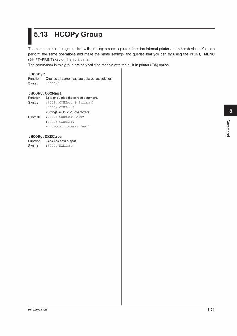
5-71IM PX8000-17EN
Com
mand
1
2
3
4
5
6
App
Index
5.13 HCOPy Group
The commands in this group deal with printing screen captures from the internal printer and other devices. You can perform the same operations and make the same settings and queries that you can by using the PRINT, MENU (SHIFT+PRINT) key on the front panel.The commands in this group are only valid on models with the built-in printer (/B5) option.
:HCOPy?Function Queries all screen capture data output settings.Syntax :HCOPy?
:HCOPy:COMMentFunction Sets or queries the screen comment.Syntax :HCOPy:COMMent {<String>}
:HCOPy:COMMent?
<String> = Up to 26 charactersExample :HCOPY:COMMENT "ABC"
:HCOPY:COMMENT?
-> :HCOPY:COMMENT "ABC"
:HCOPy:EXECuteFunction Executes data output.Syntax :HCOPy:EXECute
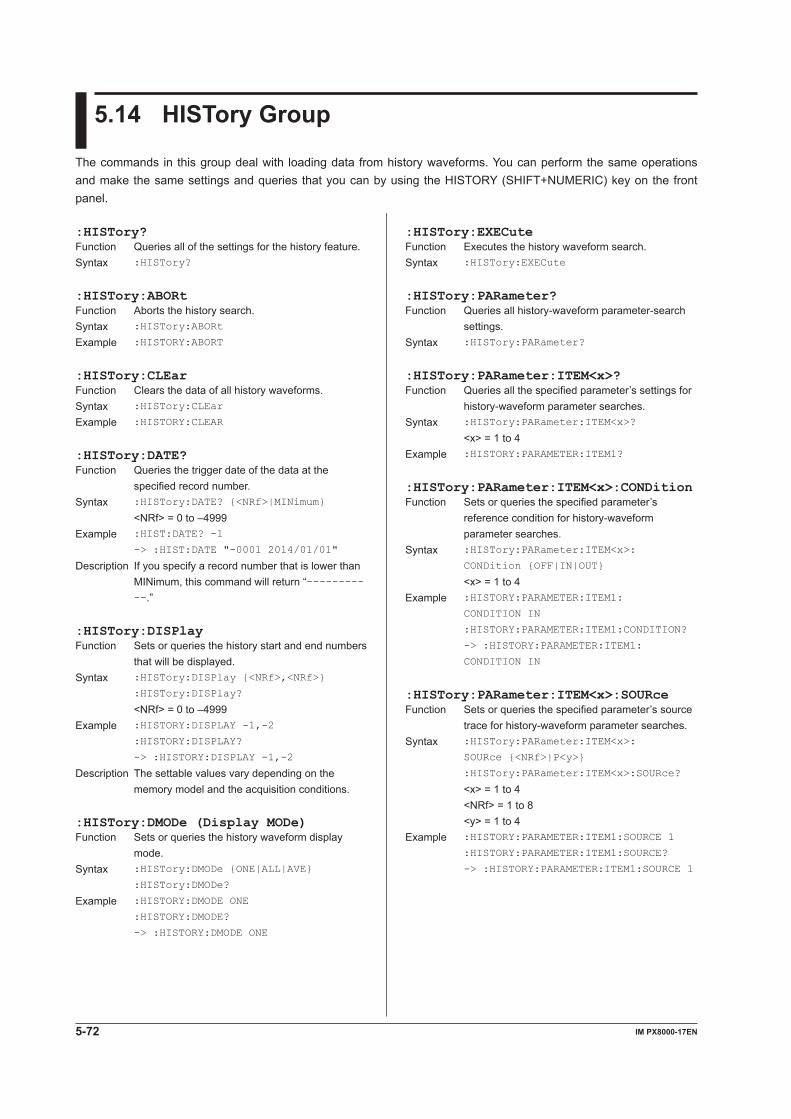
5-72 IM PX8000-17EN
5.14 HISTory Group
The commands in this group deal with loading data from history waveforms. You can perform the same operations and make the same settings and queries that you can by using the HISTORY (SHIFT+NUMERIC) key on the front panel.
:HISTory:EXECuteFunction Executes the history waveform search.Syntax :HISTory:EXECute
:HISTory:PARameter?Function Queries all history-waveform parameter-search
settings.Syntax :HISTory:PARameter?
:HISTory:PARameter:ITEM<x>?Function Queries all the specified parameter’s settings for
history-waveform parameter searches.Syntax :HISTory:PARameter:ITEM<x>?
<x> = 1 to 4Example :HISTORY:PARAMETER:ITEM1?
:HISTory:PARameter:ITEM<x>:CONDitionFunction Sets or queries the specified parameter’s
reference condition for history-waveform parameter searches.
Syntax :HISTory:PARameter:ITEM<x>:
CONDition {OFF|IN|OUT}
<x> = 1 to 4Example :HISTORY:PARAMETER:ITEM1:
CONDITION IN
:HISTORY:PARAMETER:ITEM1:CONDITION?
-> :HISTORY:PARAMETER:ITEM1:
CONDITION IN
:HISTory:PARameter:ITEM<x>:SOURceFunction Sets or queries the specified parameter’s source
trace for history-waveform parameter searches.Syntax :HISTory:PARameter:ITEM<x>:
SOURce {<NRf>|P<y>}
:HISTory:PARameter:ITEM<x>:SOURce?
<x> = 1 to 4 <NRf> = 1 to 8 <y> = 1 to 4Example :HISTORY:PARAMETER:ITEM1:SOURCE 1
:HISTORY:PARAMETER:ITEM1:SOURCE?
-> :HISTORY:PARAMETER:ITEM1:SOURCE 1
:HISTory?Function Queries all of the settings for the history feature.Syntax :HISTory?
:HISTory:ABORtFunction Aborts the history search.Syntax :HISTory:ABORt
Example :HISTORY:ABORT
:HISTory:CLEarFunction Clears the data of all history waveforms.Syntax :HISTory:CLEar
Example :HISTORY:CLEAR
:HISTory:DATE?Function Queries the trigger date of the data at the
specified record number.Syntax :HISTory:DATE? {<NRf>|MINimum}
<NRf> = 0 to –4999Example :HIST:DATE? -1
-> :HIST:DATE "-0001 2014/01/01"
Description If you specify a record number that is lower than MINimum, this command will return “-----------.”
:HISTory:DISPlayFunction Sets or queries the history start and end numbers
that will be displayed.Syntax :HISTory:DISPlay {<NRf>,<NRf>}
:HISTory:DISPlay?
<NRf> = 0 to –4999Example :HISTORY:DISPLAY -1,-2
:HISTORY:DISPLAY?
-> :HISTORY:DISPLAY -1,-2
Description The settable values vary depending on the memory model and the acquisition conditions.
:HISTory:DMODe (Display MODe)Function Sets or queries the history waveform display
mode.Syntax :HISTory:DMODe {ONE|ALL|AVE}
:HISTory:DMODe?
Example :HISTORY:DMODE ONE
:HISTORY:DMODE?
-> :HISTORY:DMODE ONE
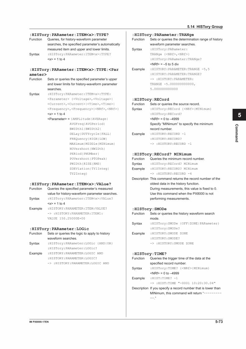
5-73IM PX8000-17EN
Com
mand
1
2
3
4
5
6
App
Index
:HISTory:PARameter:ITEM<x>:TYPE?Function Queries, for history-waveform parameter
searches, the specified parameter’s automatically measured item and upper and lower limits.
Syntax :HISTory:PARameter:ITEM<x>:TYPE?
<x> = 1 to 4
:HISTory:PARameter:ITEM<x>:TYPE:<Parameter>Function Sets or queries the specified parameter’s upper
and lower limits for history-waveform parameter searches.
Syntax :HISTory:PARameter:ITEM<x>:TYPE:
<Parameter> {<Voltage>,<Voltage>|
<Current>,<Current>|<Time>,<Time>|
<Frequency>,<Frequency>|<NRf>,<NRf>}
<x> = 1 to 4 <Parameter> = {AMPLitude|AVERage|
AVGFreq|AVGPeriod|
BWIDth1|BWIDth2|
DELay|DUTYcycle|FALL|
FREQuency|HIGH|LOW|
MAXimum|MIDDle|MINimum|
NOVershoot|NWIDth|
PERiod|PNUMber|
POVershoot|PTOPeak|
PWIDth|RISE|RMS|
SDEViation|TY1Integ|
TY2Integ}
:HISTory:PARameter:ITEM<x>:VALue?Function Queries the specified parameter’s measured
value for history-waveform parameter searches.Syntax :HISTory:PARameter:ITEM<x>:VALue?
<x> = 1 to 4Example :HISTORY:PARAMETER:ITEM:VALUE?
-> :HISTORY:PARAMETER:ITEM1:
VALUE 150.25000E+00
:HISTory:PARameter:LOGicFunction Sets or queries the logic to apply to history
waveform searches.Syntax :HISTory:PARameter:LOGic {AND|OR}
:HISTory:PARameter:LOGic?
Example :HISTORY:PARAMETER:LOGIC AND
:HISTORY:PARAMETER:LOGIC?
-> :HISTORY:PARAMETER:LOGIC AND
:HISTory:PARameter:TRANgeFunction Sets or queries the determination range of history
waveform parameter searches.Syntax :HISTory:PARameter:
TRANge {<NRf>,<NRf>}
:HISTory:PARameter:TRANge?
<NRf> = –5 to 5 divExample :HISTORY:PARAMETER:TRANGE -5,5
:HISTORY:PARAMETER:TRANGE?
-> :HISTORY:PARAMETER:
TRANGE -5.000000000000,
5.000000000000
:HISTory:RECordFunction Sets or queries the source record.Syntax :HISTory:RECord {<NRf>|MINimum}
:HISTory:RECord?
<NRf> = 0 to –4999 Specify “MINimum” to specify the minimum
record number.Example :HISTORY:RECORD -1
:HISTORY:RECORD?
-> :HISTORY:RECORD -1
:HISTory:RECord? MINimumFunction Queries the minimum record number.Syntax :HISTory:RECord? MINimum
Example :HISTORY:RECORD? MINimum
-> :HISTORY:RECORD -4
Description This command returns the record number of the oldest data in the history function.
During measurements, this value is fixed to 0. Use this command when the PX8000 is not performing measurements.
:HISTory:SMODeFunction Sets or queries the history waveform search
mode.Syntax :HISTory:SMODe {OFF|ZONE|PARameter}
:HISTory:SMODe?
Example :HISTORY:SMODE ZONE
:HISTORY:SMODE?
-> :HISTORY:SMODE ZONE
:HISTory:TIME?Function Queries the trigger time of the data at the
specified record number.Syntax :HISTory:TIME? {<NRf>|MINimum}
<NRf> = 0 to –4999Example :HIST:TIME? -1
-> :HIST:TIME "-0001 10:20:30.04"
Description If you specify a record number that is lower than MINimum, this command will return “-----------.”
5.14 HISTory Group
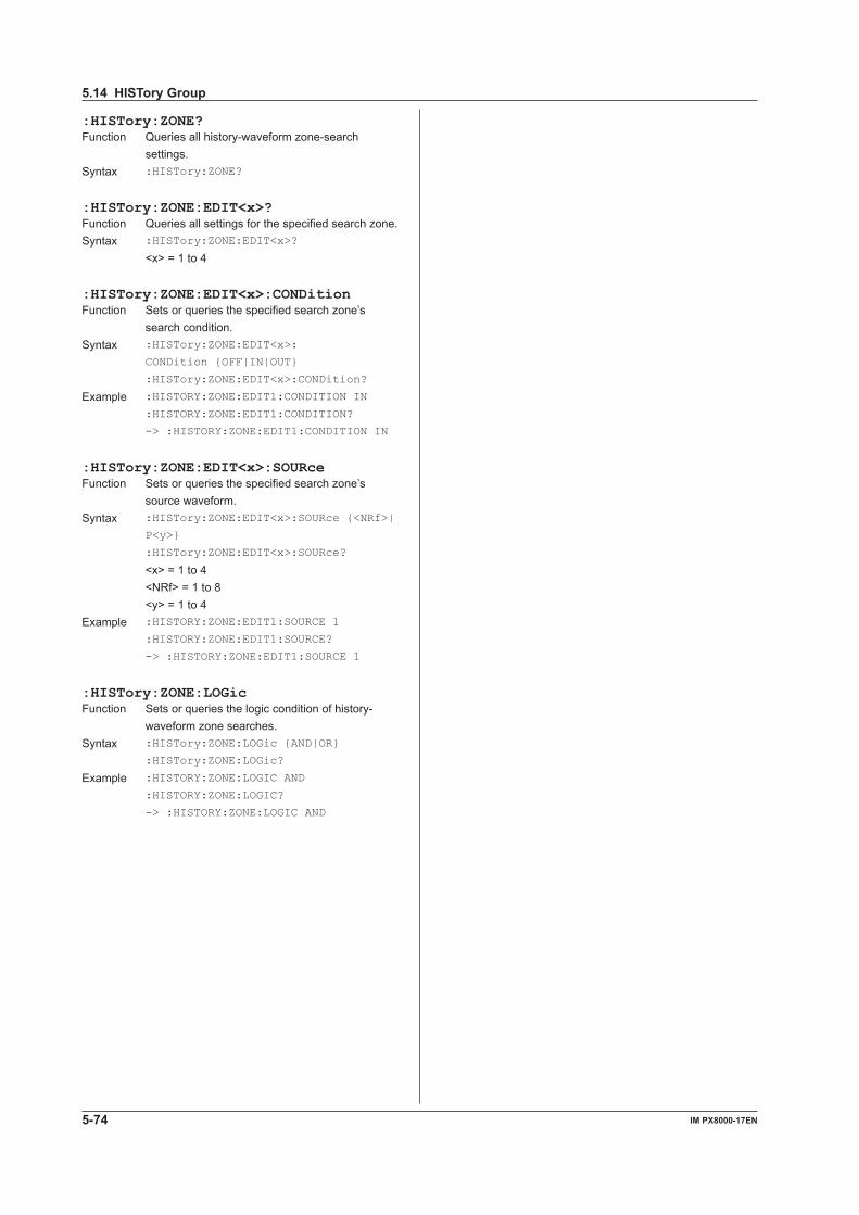
5-74 IM PX8000-17EN
:HISTory:ZONE?Function Queries all history-waveform zone-search
settings.Syntax :HISTory:ZONE?
:HISTory:ZONE:EDIT<x>?Function Queries all settings for the specified search zone.Syntax :HISTory:ZONE:EDIT<x>?
<x> = 1 to 4
:HISTory:ZONE:EDIT<x>:CONDitionFunction Sets or queries the specified search zone’s
search condition.Syntax :HISTory:ZONE:EDIT<x>:
CONDition {OFF|IN|OUT}
:HISTory:ZONE:EDIT<x>:CONDition?
Example :HISTORY:ZONE:EDIT1:CONDITION IN
:HISTORY:ZONE:EDIT1:CONDITION?
-> :HISTORY:ZONE:EDIT1:CONDITION IN
:HISTory:ZONE:EDIT<x>:SOURceFunction Sets or queries the specified search zone’s
source waveform.Syntax :HISTory:ZONE:EDIT<x>:SOURce {<NRf>|
P<y>}
:HISTory:ZONE:EDIT<x>:SOURce?
<x> = 1 to 4 <NRf> = 1 to 8 <y> = 1 to 4Example :HISTORY:ZONE:EDIT1:SOURCE 1
:HISTORY:ZONE:EDIT1:SOURCE?
-> :HISTORY:ZONE:EDIT1:SOURCE 1
:HISTory:ZONE:LOGicFunction Sets or queries the logic condition of history-
waveform zone searches.Syntax :HISTory:ZONE:LOGic {AND|OR}
:HISTory:ZONE:LOGic?
Example :HISTORY:ZONE:LOGIC AND
:HISTORY:ZONE:LOGIC?
-> :HISTORY:ZONE:LOGIC AND
5.14 HISTory Group
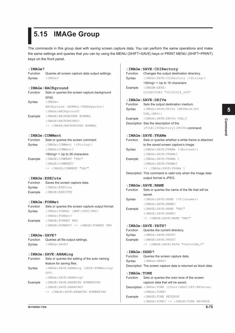
5-75IM PX8000-17EN
Com
mand
1
2
3
4
5
6
App
Index
5.15 IMAGe Group
The commands in this group deal with saving screen capture data. You can perform the same operations and make the same settings and queries that you can by using the MENU (SHIFT+SAVE) keys or PRINT MENU (SHIFT+PRINT) keys on the front panel.
:IMAGe:SAVE:CDIRectoryFunction Changes the output destination directory.Syntax :IMAGe:SAVE:CDIRectory {<String>}
<String> = Up to 16 charactersExample :IMAGW:SAVE:
CDIRECTORY "20100318_000"
:IMAGe:SAVE:DRIVeFunction Sets the output destination medium.Syntax :IMAGe:SAVE:DRIVe {NETWork|SD|
USB,<NRf>}
Example :IMAGe:SAVE:DRIVe USB,0
Description See the description of the :FILE[:DIRectory]:DRIVe command.
:IMAGe:SAVE:FRAMeFunction Sets or queries whether a white frame is attached
to the saved screen capture’s image.Syntax :IMAGe:SAVE:FRAMe {<Boolean>}
:IMAGe:SAVE:FRAMe?
Example :IMAGe:SAVE:FRAMe 1
:IMAGe:SAVE:FRAMe?
-> :IMAGe:SAVE:FRAMe 1
Description This command is valid only when the image data output format is JPEG.
:IMAGe:SAVE:NAMEFunction Sets or queries the name of the file that will be
saved.Syntax :IMAGe:SAVE:NAME {<Filename>}
:IMAGe:SAVE:NAME?
Example :IMAGE:SAVE:NAME "ABC"
:IMAGE:SAVE:NAME?
-> :IMAGE:SAVE:NAME "ABC"
:IMAGe:SAVE:PATH?Function Queries the current directory.Syntax :IMAGe:SAVE:PATH?
Example :IMAGE:SAVE:PATH?
-> :IMAGE:SAVE:PATH "Path=USB,0"
:IMAGe:SEND?Function Queries the screen capture data.Syntax :IMAGe:SEND?
Description The screen capture data is returned as block data.
:IMAGe:TONEFunction Sets or queries the color tone of the screen
capture data that will be saved.Description :IMAGe:TONE {COLor|GRAY|OFF|REVerse} :IMAGe:TONE?
Example :IMAGE:TONE REVERSE
:IMAGE:TONE? -> :IMAGE:TONE REVERSE
:IMAGe?Function Queries all screen capture data output settings.Syntax :IMAGe?
:IMAGe:BACKgroundFunction Sets or queries the screen capture background
(png).Syntax :IMAGe:
BACKground {NORMal|TRANsparent}
:IMAGe:BACKground?
Example :IMAGE:BACKGROUND NORMAL
:IMAGE:BACKGROUND?
-> :IMAGE:BACKGROUND NORMAL
:IMAGe:COMMentFunction Sets or queries the screen comment.Syntax :IMAGe:COMMent {<String>}
:IMAGe:COMMent?
<String> = Up to 26 charactersExample :IMAGE:COMMENT "ABC"
:IMAGE:COMMENT?
-> :IMAGE:COMMENT "ABC"
:IMAGe:EXECuteFunction Saves the screen capture data.Syntax :IMAGe:EXECute
Example :IMAGE:EXECUTE
:IMAGe:FORMatFunction Sets or queries the screen capture output format.Syntax :IMAGe:FORMat {BMP|JPEG|PNG}
:IMAGe:FORMat?
Example :IMAGE:FORMAT PNG
:IMAGE:FORMAT? -> :IMAGE:FORMAT PNG
:IMAGe:SAVE?Function Queries all file output settings.Syntax :IMAGe:SAVE?
:IMAGe:SAVE:ANAMingFunction Sets or queries the setting of the auto naming
feature for saving files.Syntax :IMAGe:SAVE:ANAMing {DATE|NUMBering|
OFF}
:IMAGe:SAVE:ANAMing?
Example :IMAGE:SAVE:ANAMING NUMBERING
:IMAGE:SAVE:ANAMING?
-> :IMAGE:SAVE:ANAMING NUMBERING
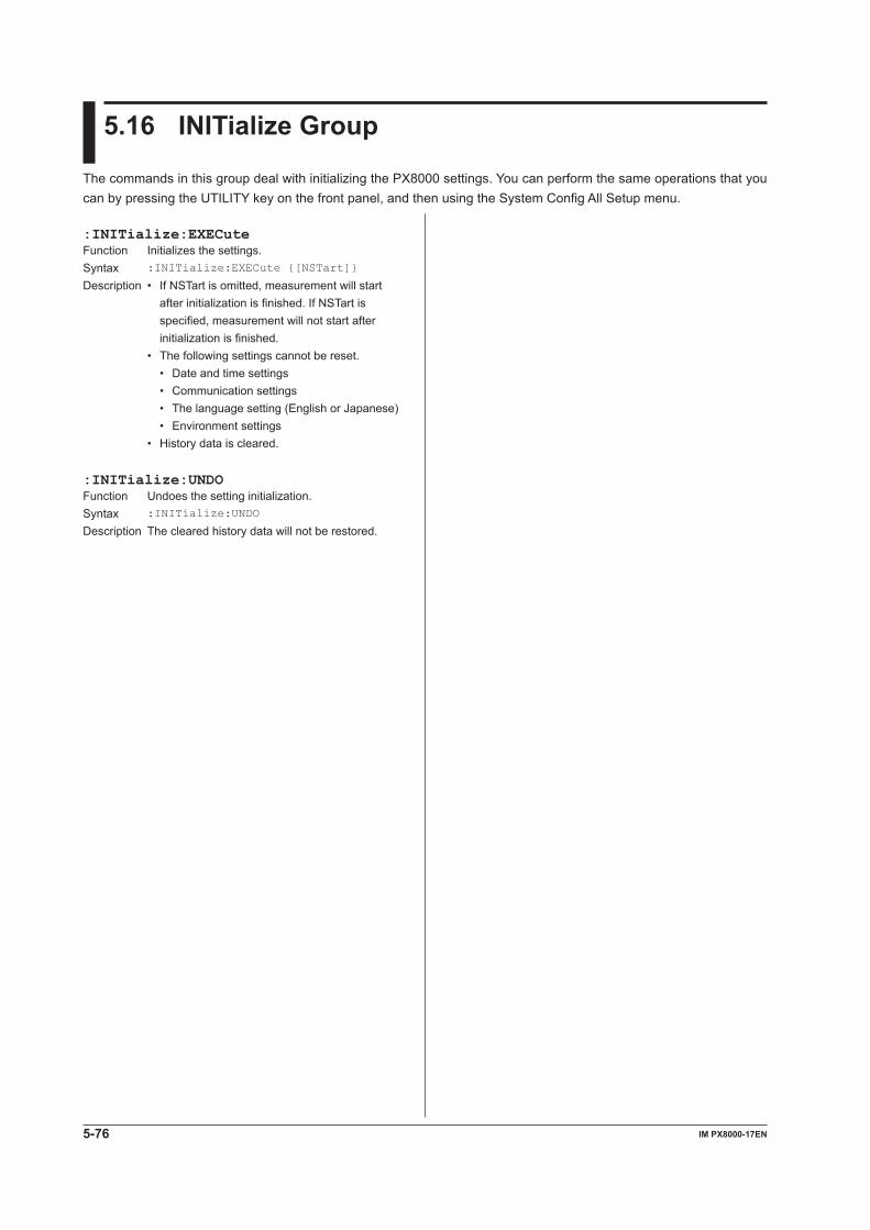
5-76 IM PX8000-17EN
5.16 INITialize Group
The commands in this group deal with initializing the PX8000 settings. You can perform the same operations that you can by pressing the UTILITY key on the front panel, and then using the System Config All Setup menu.
:INITialize:EXECuteFunction Initializes the settings. Syntax :INITialize:EXECute {[NSTart]}
Description • If NSTart is omitted, measurement will start after initialization is finished. If NSTart is specified, measurement will not start after initialization is finished.
• The following settings cannot be reset. • Date and time settings • Communication settings • The language setting (English or Japanese) • Environment settings • History data is cleared.
:INITialize:UNDOFunction Undoes the setting initialization.Syntax :INITialize:UNDO
Description The cleared history data will not be restored.

5-77IM PX8000-17EN
Com
mand
1
2
3
4
5
6
App
Index
5.17 INPut Group
The commands in this group deal with the measurement conditions of the power measurement elements. You can perform the same operations and make the same settings and queries that you can by using the ELEM1 to ELEM4, CH1 to CH8, WIRING, NULL, and NULL SET (SHIFT+NULL) keys on the front panel.
:INPut?Function Queries all power measurement element settings.Syntax :INPut?
[:INPut]:CURRent?Function Queries all electric current measurement settings.Syntax [:INPut]:CURRent?
[:INPut]:CURRent:AUTO?Function Queries the electric current auto range on/off
statuses of all elements.Syntax [:INPut]:CURRent:AUTO?
[:INPut]:CURRent:AUTO[:ALL]Function Collectively sets the electric current auto range
on/off status of all elements.Syntax [:INPut]:CURRent:AUTO[:ALL]
{<Boolean>}
Example :INPUT:CURRENT:AUTO:ALL ON
[:INPut]:CURRent:AUTO:ELEMent<x>Function Sets or queries the electric current auto range on/
off status of the specified element.Syntax [:INPut]:CURRent:AUTO:
ELEMent<x> {<Boolean>}
[:INPut]:CURRent:AUTO:ELEMent<x>?
<x> = 1 to 4 (element)Example :INPUT:CURRENT:AUTO:ELEMENT1 ON
:INPUT:CURRENT:AUTO:ELEMENT1?
-> :INPUT:CURRENT:AUTO:ELEMENT1 1
[:INPut]:CURRent:AUTO:{SIGMA|SIGMB}Function Collectively sets the electric current auto range
on/off status of all the elements that belong to the specifiedwiringunit(ΣAorΣB).
Syntax [:INPut]:CURRent:AUTO:
{SIGMA|SIGMB} {<Boolean>}
Example :INPUT:CURRENT:AUTO:SIGMA ON
Description SIGMA or SIGMB is invalid if the wiring system setting ([:INPut]:WIRing) is made in such a waythatthecorrespondingwiringunit(ΣAorΣB)does not exist.
[:INPut]:CURRent:EXTSensor?Function Queries all external current sensor range settings.Syntax [:INPut]:CURRent:EXTSensor?
[:INPut]:CURRent:EXTSensor:DISPlayFunction Sets or queries the display mode of the external
current sensor range.Syntax [:INPut]:CURRent:EXTSensor:
DISPlay {DIRect|MEASure}
[:INPut]:CURRent:EXTSensor:DISPlay?
Example :INPUT:CURRENT:EXTSENSOR:
DISPLAY DIRECT
:INPUT:CURRENT:EXTSENSOR:DISPLAY?
-> :INPUT:CURRENT:EXTSENSOR:
DISPLAY DIRECT
[:INPut]:CURRent:RANGe?Function Queries the electric current ranges of all elements.Syntax [:INPut]:CURRent:RANGe?
[:INPut]:CURRent:RANGe[:ALL]Function Collectively sets the electric current range of all
elements.Syntax [:INPut]:CURRent:RANGe[:
ALL] {<Current>|(EXTernal,<Voltage>)}
<Current> = 10 mA, 20 mA, 50 mA, 100 mA, 200 mA, 500 mA, 1 A, 2 A, 5 A (for direct current input)
<Voltage> = 50 mV, 100 mV, 200 mV, 500 mV, 1 V, 2 V, 5 V, 10 V (for external current sensor input)
Example :INPUT:CURRENT:RANGE:ALL 5A
:INPUT:CURRENT:RANGE:ALL EXTERNAL,10V
[:INPut]:CURRent:RANGe:ELEMent<x>Function Sets or queries the electric current range of the
specified element.Syntax [:INPut]:CURRent:RANGe:
ELEMent<x> {<Current>|(EXTernal,
<Voltage>)}
[:INPut]:CURRent:RANGe:ELEMent<x>?
<x> = 1 to 4 (element) <Current>, <Voltage>
= See [:INPut]:CURRent:RANGe[:ALL]Example :INPUT:CURRENT:RANGE:ELEMENT1 5A
:INPUT:CURRENT:RANGE:ELEMENT1?
-> :INPUT:CURRENT:RANGE:
ELEMENT1 5.00E+00
:INPUT:CURRENT:RANGE:
ELEMENT1 EXTERNAL,10V
:INPUT:CURRENT:RANGE:ELEMENT1?
-> :INPUT:CURRENT:RANGE:
ELEMENT1 EXTERNAL,10.00E+00
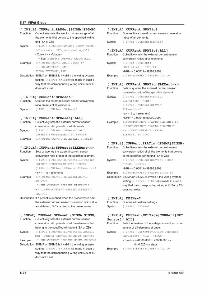
5-78 IM PX8000-17EN
[:INPut]:CURRent:RANGe:{SIGMA|SIGMB}Function Collectively sets the electric current range of all
the elements that belong to the specified wiring unit(ΣAorΣB).
Syntax [:INPut]:CURRent:RANGe:{SIGMA|SIGMB}
{<Current>|(EXTernal,<Voltage>)}
<Current>, <Voltage> = See [:INPut]:CURRent:RANGe[:ALL]
Example :INPUT:CURRENT:RANGE:SIGMA 5A
:INPUT:CURRENT:RANGE:
SIGMA EXTERNAL,10V
Description SIGMA or SIGMB is invalid if the wiring system setting ([:INPut]:WIRing) is made in such a waythatthecorrespondingwiringunit(ΣAorΣB)does not exist.
[:INPut]:CURRent:SPReset?Function Queries the external current sensor conversion
ratio presets of all elements.Syntax [:INPut]:CURRent:SPReset?
[:INPut]:CURRent:SPReset[:ALL]Function Collectively sets the external current sensor
conversion ratio presets of all elements.Syntax [:INPut]:CURRent:SPReset[:ALL]
{OTHERS|SHUNT20|SHUNT10|SHUNT5}
Example :INPUT:CURRENT:SPRESET:ALL SHUNT20
[:INPut]:CURRent:SPReset:ELEMent<x>Function Sets or queries the external current sensor
conversion ratio preset of the specified element.Syntax [:INPut]:CURRent:SPReset:ELEMent<x>
{OTHERS|SHUNT20|SHUNT10|SHUNT5}
[:INPut]:CURRent:SPReset:ELEMent<x>?
<x> = 1 to 4 (element)Example :INPUT:CURRENT:SPRESET:ELEMENT1
SHUNT20
:INPUT:CURRENT:SPRESET:ELEMENT1?
-> :INPUT:CURRENT:SPRESET:ELEMENT1
SHUNT20
Description If a preset is queried when the preset value and the external current sensor conversion ratio value are different, "A" is added to the preset name.
[:INPut]:CURRent:SPReset:{SIGMA|SIGMB}Function Collectively sets the external current sensor
conversion ratio presets of all the elements that belongtothespecifiedwiringunit(ΣAorΣB).
Syntax [:INPut]:CURRent:SPReset:{SIGMA|SIG
MB} {OTHERS|SHUNT20|SHUNT10|SHUNT5}
Example :INPUT:CURRENT:SPRESET:SIGMA SHUNT20
Description SIGMA or SIGMB is invalid if the wiring system setting ([:INPut]:WIRing) is made in such a waythatthecorrespondingwiringunit(ΣAorΣB)does not exist.
[:INPut]:CURRent:SRATio?Function Queries the external current sensor conversion
ratios of all elements.Syntax [:INPut]:CURRent:SRATio?
[:INPut]:CURRent:SRATio[:ALL]Function Collectively sets the external current sensor
conversion ratios of all elements.Syntax [:INPut]:CURRent:
SRATio[:ALL] {<NRf>}
<NRf> = 0.0001 to 99999.9999Example :INPUT:CURRENT:SRATIO:ALL 10
[:INPut]:CURRent:SRATio:ELEMent<x>Function Sets or queries the external current sensor
conversion ratio of the specified element.Syntax [:INPut]:CURRent:SRATio:
ELEMent<x> {<NRf>}
[:INPut]:CURRent:SRATio:
ELEMent<x>?
<x> = 1 to 4 (element) <NRf> = 0.0001 to 99999.9999Example :INPUT:CURRENT:SRATIO:ELEMENT1 10
:INPUT:CURRENT:SRATIO:ELEMENT1?
-> :INPUT:CURRENT:SRATIO:
ELEMENT1 10.0000
[:INPut]:CURRent:SRATio:{SIGMA|SIGMB}Function Collectively sets the external current sensor
conversion ratios of all the elements that belong tothespecifiedwiringunit(ΣAorΣB).
Syntax [:INPut]:CURRent:SRATio:{SIGMA|
SIGMB} {<NRf>}
<NRf> = 0.0001 to 99999.9999Example :INPUT:CURRENT:SRATIO:SIGMA 10
Description SIGMA or SIGMB is invalid if the wiring system setting ([:INPut]:WIRing) is made in such a waythatthecorrespondingwiringunit(ΣAorΣB)does not exist.
[:INPut]:DESKew?Function Queries all deskew settings.Syntax [:INPut]:DESKew?
[:INPut]:DESKew:{VOLTage|CURRent|EXTSensor}[:ALL]Function Sets the deskew of the voltage, current, or current
sensor of all elements at once.Syntax [:INPut]:DESKew:{VOLTage|CURRent|
EXTSensor}[:ALL] {<Time>}
<Time> = –20000.000 to 20000.000 ns (in0.625−nssteps)
Example :INPUT:DESKEW:CURRENT:ALL 10
5.17 INPut Group
5-79IM PX8000-17EN
Com
mand
1
2
3
4
5
6
App
Index
[:INPut]:DESKew:{VOLTage|CURRent|EXTSensor}:ELEMent<x>Function Sets or queries the deskew of the voltage,
current, or current sensor of an element.Syntax [:INPut]:DESKew:{VOLTage|CURRent|
EXTSensor}:ELEMent<x> {<Time>}
[:INPut]:DESKew:{VOLTage|CURRent|
EXTSensor}:ELEMent<x>?
<x> = 1 to 4 <Time> = –20000.000 to 20000.000ns
(in0.625−nssteps)Example :INPUT:DESKEW:CURRENT:ELEMENT1 10
:INPUT:DESKEW:CURRENT:ELEMENT1?
-> : INPUT:DESKEW:CURRENT:
ELEMENT1 10.000
[:INPut]:FILTer?Function Queries all input filter settings.Syntax [:INPut]:FILTer?
[:INPut]:FILTer:FREQuency?Function Queries the frequency filters of all elements.Syntax [:INPut]:FILTer:FREQuency?
[:INPut]:FILTer:FREQuency[:ALL]Function Collectively sets the frequency filter of all
elements.Syntax [:INPut]:FILTer:FREQuency[:
ALL] {OFF|<Frequency>}
OFF = Frequency filter off <Frequency> = 100 Hz, 500 Hz, 2 kHz, 20 kHz
(when the line filter is on; cutoff frequency)
Example :INPUT:FILTER:FREQUENCY:ALL OFF
[:INPut]:FILTer:FREQuency:ELEMent<x>Function Sets or queries the frequency filter of the
specified element.Syntax [:INPut]:FILTer:FREQuency:
ELEMent<x> {OFF|<Frequency>}
[:INPut]:FILTer:FREQuency:ELEMent
<x>?
<x> = 1 to 4 (element) OFF = Frequency filter off <Frequency> = 100 Hz, 500 Hz, 2 kHz, 20 kHz
(when the line filter is on; cutoff frequency)
Example :INPUT:FILTER:FREQUENCY:
ELEMENT1 100HZ
:INPUT:FILTER:FREQUENCY:ELEMENT1?
-> :INPUT:FILTER:FREQUENCY:
ELEMENT1 100.0E+00
[:INPut]:FILTer:LINE?Function Queries the line filters of all elements.Syntax [:INPut]:FILTer:LINE?
[:INPut]:FILTer[:LINE][:ALL]Function Collectively sets the line filter of all elements.Syntax [:INPut]:FILTer[:LINE][:ALL] {OFF|
<Frequency>}
OFF = Line filter off <Frequency> = 500 Hz, 2 kHz, 20 kHz, 1 MHz
(when the line filter is on; cutoff frequency)
Example :INPUT:FILTER:LINE:ALL OFF
[:INPut]:FILTer[:LINE]:ELEMent<x>Function Sets or queries the line filter of the specified
element.Syntax [:INPut]:FILTer[:LINE]:
ELEMent<x> {OFF|<Frequency>}
[:INPut]:FILTer[:LINE]:
ELEMent<x>?
<x> = 1 to 4 (element) OFF = Line filter off <Frequency> = 500 Hz, 2 kHz, 20 kHz, 1 MHz
(when the line filter is on; cutoff frequency)
Example :INPUT:FILTER:LINE:ELEMENT1 0.5KHZ
:INPUT:FILTER:LINE:ELEMENT1?
-> :INPUT:FILTER:LINE:
ELEMENT1 500.0E+00
5.17 INPut Group
5-80 IM PX8000-17EN
[:INPut]:FILTer[:LINE]:{SIGMA|SIGMB}Function Collectively sets the line filter of all the elements
that belong to the specified wiring unit (ΣA or ΣB).Syntax [:INPut]:FILTer[:LINE]:{SIGMA|
SIGMB} {OFF|<Frequency>}
OFF = Line filter off <Frequency> = 500 Hz, 2 kHz, 20 kHz, 1 MHz
(when the line filter is on; cutoff frequency)
Example :INPUT:FILTER:LINE:SIGMA 20KHZ
[:INPut]:INDependentFunction Sets or queries the on/off status of independent
power measurement element configuration.Syntax [:INPut]:INDependent {<Boolean>}
[:INPut]:INDependent?
Example :INPUT:INDEPENDENT OFF
:INPUT:INDEPENDENT?
-> :INPUT:INDEPENDENT 0
Description This command is valid only when the number of power measurement elements are two to four and all the current modules are of the same type.
[:INPut]:POVer?Function Queries the peak over-range information.Syntax [:INPut]:POVer?
Example :INPUT:POVER? -> 0
Description • With the numeric measurement result, the peak over-range information of each element is mapped as shown below. For the response, the sum of the values of each bit is returned in decimal format.
For example, a response of 16 indicates that a peak over-range is occurring at U3 or A5 (AUX5).
15 14 13 12 11 10 9 8 7 6 5 4 3 2 1 0I4 U4 I3 U3 I2 U2 I1 U1
I 4: Current of element 4 or AUX8 U4: Voltage of element 4 or AUX7 I 3: Current of element 3 or AUX6 U3: Voltage of element 3 or AUX5 I 2: Current of element 2 or AUX4 U2: Voltage of element 2 or AUX3 I 1: Current of element 1 U1: Voltage of element 1
[:INPut]:SCALing?Function Queries all scaling settings.Syntax [:INPut]:SCALing?
[:INPut]:SCALing:CTPReset?Function Queries the CT ratio presets of all elements.Syntax [:INPut]:SCALing:CTPReset?
[:INPut]:SCALing:CTPReset[:ALL]Function Collectively sets the CT ratio presets of all elements.Syntax [:INPut]:SCALing:CTPReset
[:ALL] {OTHERS|CT2000A|CT1000|CT200|
CT60}
Example :INPUT:SCALING:CTPRESET:ALL CT1000
[:INPut]:SCALing:CTPReset:ELEMent<x>Function Sets or queries the CT ratio preset of the
specified element.Syntax [:INPut]:SCALing:CTPReset:ELEMent<x>
{OTHERS|CT2000A|CT1000|CT200|CT60}
[:INPut]:SCALing:CTPReset:ELEMent<x>?
<x> = 1 to 4 (element)Example :INPUT:SCALING:CTPRESET:ELEMENT1
CT1000
:INPUT:SCALING:CTPRESET:ELEMENT1?
-> :INPUT:SCALING:CTPRESET:ELEMENT1
CT1000
Description If a preset is queried when the preset value and the CT ratio value are different, "A" is added to the preset name.
[:INPut]:SCALing:CTPReset:{SIGMA|SIGMB}Function Collectively sets the CT ratio presets of all the
elements that belong to the specified wiring unit (ΣA or ΣB).
Syntax [:INPut]:SCALing:CTPReset:{SIGMA|SIGMB} {OTHERS|CT2000A|CT1000|CT200|CT60}
Example :INPUT:SCALING:CTPRESET:SIGMA CT1000
Description SIGMA or SIGMB is invalid if the wiring system setting ([:INPut]:WIRing) is made in such a way that the corresponding wiring unit (ΣA or ΣB) does not exist.
[:INPut]:SCALing:STATe?Function Queries the on/off statuses of the scaling of all
elements.Syntax [:INPut]:SCALing:STATe?
[:INPut]:SCALing[:STATe][:ALL]Function Collectively sets the on/off status of the scaling of
all elements.Syntax [:INPut]:SCALing[:STATe][:
ALL] {<Boolean>}
Example :INPUT:SCALING:STATE:ALL OFF
[:INPut]:SCALing[:STATe]:ELEMent<x>Function Sets or queries the on/off status of the scaling of
the specified element.Syntax [:INPut]:SCALing[:STATe]:
ELEMent<x> {<Boolean>}
[:INPut]:SCALing[:STATe]:ELEMent<x>?
<x> = 1 to 4 (element)Example :INPUT:SCALING:STATE:ELEMENT1 OFF
:INPUT:SCALING:STATE:ELEMENT1?
-> :INPUT:SCALING:STATE:ELEMENT1 0
5.17 INPut Group
5-81IM PX8000-17EN
Com
mand
1
2
3
4
5
6
App
Index
[:INPut]:SCALing:{VT|CT|SFACtor}?Function Queries the VT ratios, CT ratios, or power
coefficients of all elements.Syntax [:INPut]:SCALing:{VT|CT|SFACtor}?
[:INPut]:SCALing:{VT|CT|SFACtor}[:ALL]Function Collectively sets the VT ratio, CT ratio, or power
coefficient of all elements.Syntax [:INPut]:SCALing:{VT|CT|SFACtor}
[:ALL] {<NRf>}
<NRf> = 0.0001 to 99999.9999Example :INPUT:SCALING:VT:ALL 1
[:INPut]:SCALing:{VT|CT|SFACtor}:ELEMent<x>Function Sets or queries the VT ratio, CT ratio, or power
coefficient of the specified element.Syntax [:INPut]:SCALing:{VT|CT|SFACtor}:ELE
Ment<x> {<NRf>}
[:INPut]:SCALing:{VT|CT|SFACtor}:ELE
Ment<x>?
<x> = 1 to 4 (element) <NRf> = 0.0001 to 99999.9999Example :INPUT:SCALING:VT:ELEMENT1 1
:INPUT:SCALING:VT:ELEMENT1?
-> :INPUT:SCALING:VT:ELEMENT1 1.0000
[:INPut]:SCALing:{VT|CT|SFACtor}:{SIGMA|SIGMB}Function Collectively sets the VT ratio, CT ratio, or power
coefficient of all the elements that belong to the specifiedwiringunit(ΣAorΣB).
Syntax [:INPut]:SCALing:{VT|CT|SFACtor}: {SIGMA|SIGMB} {<NRf>}
<NRf> = 0.0001 to 99999.9999Example :INPUT:SCALING:VT:SIGMA 1
Description SIGMA or SIGMB is invalid if the wiring system setting ([:INPut]:WIRing) is made in such a waythatthecorrespondingwiringunit(ΣAorΣB)does not exist.
[:INPut]:SYNChronize?Function Queries the synchronization sources of all
elements.Syntax [:INPut]:SYNChronize?
[:INPut]:SYNChronize[:ALL]Function Collectively sets the synchronization source of all
elements.Syntax [:INPut]:SYNChronize[:ALL] {U<x>|
I<x>|EXTernal|NONE}
<x> = 1 to 4 (element) EXTernal = External trigger input (Ext Trigger In) NONE = No synchronization sourceExample :INPUT:SYNCHRONIZE:ALL I1
[:INPut]:SYNChronize:ELEMent<x>Function Sets or queries the synchronization source of the
specified element.Syntax [:INPut]:SYNChronize:
ELEMent<x> {U<x>|I<x>|EXTernal|NONE}
[:INPut]:SYNChronize:ELEMent<x>?
<x> = 1 to 4 (element) EXTernal = External trigger input (Ext Trigger In) NONE = No synchronization sourceExample :INPUT:SYNCHRONIZE:ELEMENT1 I1
:INPUT:SYNCHRONIZE:ELEMENT1?
-> :INPUT:SYNCHRONIZE:ELEMENT1 I1
[:INPut]:SYNChronize:{SIGMA|SIGMB}Function Collectively sets the synchronization source of all
the elements that belong to the specified wiring unit(ΣAorΣB).
Syntax [:INPut]:SYNChronize:{SIGMA|
SIGMB} {U<x>|I<x>|EXTernal|NONE}
<x> = 1 to 4 (element) EXTernal = External trigger input (Ext Trigger In) NONE = No synchronization sourceExample :INPUT:SYNCHRONIZE:SIGMA I1
Description SIGMA or SIGMB is invalid if the wiring system setting ([:INPut]:WIRing) is made in such a waythatthecorrespondingwiringunit(ΣAorΣB)does not exist.
[:INPut]:VOLTage?Function Queries all voltage measurement settings.Syntax [:INPut]:VOLTage?
[:INPut]:VOLTage:AUTO?Function Queries the voltage auto range on/off statuses of
all elements.Syntax [:INPut]:VOLTage:AUTO?
[:INPut]:VOLTage:AUTO[:ALL]Function Collectively sets the voltage auto range on/off
status of all elements.Syntax [:INPut]:VOLTage:AUTO[:
ALL] {<Boolean>}
Example :INPUT:VOLTAGE:AUTO:ALL ON
[:INPut]:VOLTage:AUTO:ELEMent<x>Function Sets or queries the voltage auto range on/off
status of the specified element.Syntax [:INPut]:VOLTage:AUTO:
ELEMent<x> {<Boolean>}
[:INPut]:VOLTage:AUTO:ELEMent<x>?
<x> = 1 to 4 (element)Example :INPUT:VOLTAGE:AUTO:ELEMENT1 ON
:INPUT:VOLTAGE:AUTO:ELEMENT1?
-> :INPUT:VOLTAGE:AUTO:ELEMENT1 1
5.17 INPut Group
5-82 IM PX8000-17EN
[:INPut]:VOLTage:AUTO:{SIGMA|SIGMB}Function Collectively sets the voltage auto range on/
off status of all the elements that belong to the specifiedwiringunit(ΣAorΣB).
Syntax [:INPut]:VOLTage:AUTO:{SIGMA|
SIGMB} {<Boolean>}
Example :INPUT:VOLTAGE:AUTO:SIGMA ON
Description SIGMA or SIGMB, is invalid if the wiring system setting ([:INPut]:WIRing) is made in such a waythatthecorrespondingwiringunit(ΣAorΣB)does not exist.
[:INPut]:VOLTage:RANGe?Function Queries the voltage ranges of all elements.Syntax [:INPut]:VOLTage:RANGe?
[:INPut]:VOLTage:RANGe[:ALL]Function Collectively sets the voltage range of all elements.Syntax [:INPut]:VOLTage:RANGe[:
ALL] {<Voltage>}
<Voltage> = 1.5 V, 3 V, 6 V, 10 V, 15 V, 30 V, 60 V, 100 V, 150 V, 300 V, 600 V, 1000 V
Example :INPUT:VOLTAGE:RANGE:ALL 1000V
[:INPut]:VOLTage:RANGe:ELEMent<x>Function Sets or queries the voltage range of the specified
element.Syntax [:INPut]:VOLTage:RANGe:
ELEMent<x> {<Voltage>}
[:INPut]:VOLTage:RANGe:ELEMent<x>?
<x> = 1 to 4 (element) <Voltage> = See [:INPut]:VOLTage:
RANGe[:ALL]
Example :INPUT:VOLTAGE:RANGE:ELEMENT1 1000V
:INPUT:VOLTAGE:RANGE:ELEMENT1?
-> :INPUT:VOLTAGE:RANGE:
ELEMENT1 1.000E+03
[:INPut]:VOLTage:RANGe:{SIGMA|SIGMB}Function Collectively sets the voltage range of all the
elements that belong to the specified wiring unit (ΣAorΣB).
Syntax [:INPut]:VOLTage:RANGe:{SIGMA|
SIGMB} {<Voltage>}
<Voltage> = See [:INPut]:VOLTage:RANGe[:ALL]
Example :INPUT:VOLTAGE:RANGE:SIGMA 1000V
Description SIGMA or SIGMB is invalid if the wiring system setting ([:INPut]:WIRing) is made in such a waythatthecorrespondingwiringunit(ΣAorΣB)does not exist.
[:INPut]:WIRingFunction Sets or queries the wiring system.Syntax [:INPut]:WIRing {(P1W2|P1W3|P3W3|
P3W4|V3A3)[,(P1W2|P1W3|P3W3|P3W4|
V3A3|NONE)]}
[:INPut]:WIRing?
P1W2 = Single-phase, two-wire system [1P2W] P1W3 = Single-phase, three-wire system [1P3W] P3W3 = Three-phase, three-wire system [3P3W] P3W4 = Three-phase, four-wire system [3P4W] V3A3 = Three-phase, three-wire system with a
three-voltage, three-current method [3P3W(3V3A)]
NONE = No wiringExample Example when there are three power
measurement elements :INPUT:WIRING P1W2,P3W3
:INPUT:WIRING?
-> :INPUT:WIRING P1W2,P3W3
:INPUT:WIRING P3W4
:INPUT:WIRING?
-> :INPUT:WIRING P3W4
Description • Set the wiring system pattern in order starting from the element with the smallest number.
• Some wiring system patterns are not selectable depending on the number of power measurement elements that are installed. For details on the available wiring system patterns, see the features guide, IM PX8000-01EN.
• The pattern is fixed to P1W2 when there is one power measurement element. No other setting is allowed.
5.17 INPut Group
5-83IM PX8000-17EN
Com
mand
1
2
3
4
5
6
App
Index
5.18 LSTart Group
The commands in this group deal with immediately starting the log operation. These commands set the trigger mode to On Start and start waveform acquisition.
:LSTart (Log STart)Function Starts waveform acquisition immediately.Syntax :LSTart
:LSTart?Function Starts waveform acquisition immediately, and
waits for acquisition to complete.Syntax :LSTart?
Example :LSTart? -> 0
Description When acquisition is complete, this command returns 0.
5-84 IM PX8000-17EN
5.19 MATH Group
The commands in this group deal with computations. You can make the same settings and queries that you can by using the MATH key on the front panel.If the selectable range of the time axis is “<NRf> = –5 to 5div,” the selectable range varies depending on settings such as the record length. For details, see “Selectable Range of Cursor Positions” under “Notes about Cursor Measurement” in chapter 15 of IM PX8000-01EN.
:MATH<x>?Function Queries all computation settings.Syntax :MATH<x>?
<x> = 1 to 8
:MATH<x>:BINary?Function Queries all binary computation settings.Syntax :MATH<x>:BINary?
<x> = 1 to 8
:MATH<x>:BINary:{CHANnel<x>|POWer<y>|MATH<x>}[:THReshold]Function Sets or queries the threshold level of the specified
channel for binary computations.Syntax :MATH<x>:BINary:
{CHANnel<x>|POWer<y>|MATH<x>}
[:THReshold] {<Voltage>,<Voltage>|
<Current>,<Current>|<NRf>,<NRf>}
:MATH<x>:BINary:{CHANnel<x>|POWer<y>|
MATH<x>}[:THReshold]?
<x> of MATH<x> = 1 to 8 <x> of CHANnel<x> = 1 to 8 <y> = 1 to 4 <Voltage>, <Current>, and <NRf>
= The selectable range varies depending on settings such as the range and offset. For details, see the features guide, IM PX8000-01EN.
• For settings other than MATH<x> <NRf> = –10 to 10 div (or equivalent values)
• For MATH<x> <NRf> = –5 to 5 (div; in 0.01 div steps)
Example :MATH1:BINARY:CHANNEL1:THRESHOLD 1,0
:MATH1:BINARY:CHANNEL1:THRESHOLD?
-> :MATH1:BINARY:CHANNEL1:
THRESHOLD 1.000000E+00,
0.000000E+00
:MATH<x>:CONStant<x>Function Sets or queries a constant for user-defined
computation.Syntax :MATH<x>:CONStant<x> {<NRf>}
:MATH<x>:CONStant<x>?
<x> of MATH<x> = 1 to 8 (this command performs the same no matter what value you specify)
<x> of CONStant<x> = 1 to 8 <NRf> = –9.9999E+30 to +9.9999E+30Example :MATH1:CONSTANT1 1
:MATH1:CONSTANT1?
-> :MATH1:CONSTANT1 1
:MATH<x>:DEFineFunction Sets or queries an expression for user-defined
computation.Syntax :MATH<x>:DEFine {<String>}
:MATH<x>:DEFine?
<x> = 1 to 8 <String> = Up to 80 charactersExample :MATH1:DEFINE "PS(C1)"
:MATH1:DEFINE?
-> :MATH1:DEFINE "PS(C1)"
Description If OPERation is set to a value other than USERdefine, this query will return the OPERation setting.
:MATH<x>:DISPlayFunction Sets or queries whether computations will be
performed.Syntax :MATH<x>:DISPlay {<Boolean>}
:MATH<x>:DISPlay?
<x> = 1 to 8Example :MATH1:DISPLAY ON
:MATH1:DISPLAY? -> :MATH1:DISPLAY 1
5-85IM PX8000-17EN
Com
mand
1
2
3
4
5
6
App
Index
:MATH<x>:ESHift:{CHANnel<x>|POWer<y>|MATH<x>}[:COUNt]Function Sets or queries the amount of phase shift in the
Shift computation when an external clock is used.Syntax :MATH<x>:ESHift:{CHANnel<x>|POWer<y>|
MATH<x>}[:COUNt] {<NRf>}
:MATH<x>:ESHift:{CHANnel<x>|POWer<y>|
MATH<x>}[:COUNt]?
<x> of MATH<x> = 1 to 8 <x> of CHANnel<x> = 1 to 8 <y> = 1 to 4 <NRf> = ±(record length/2). The resolution is 1.Example :MATH1:ESHIFT:CHANNEL1:COUNT 10
:MATH1:ESHIFT:CHANNEL1:COUNT?
-> :MATH1:ESHIFT:CHANNEL1:COUNT 10
:MATH<x>:EXPonential?Function Queries all exponential window settings.Syntax :MATH<x>:EXPonential?
<x> = 1 to 8 (this command performs the same no matter what value you specify)
:MATH<x>:EXPonential:DRATeFunction Sets or queries the exponential window’s
damping rate.Syntax :MATH<x>:EXPonential:DRATe {<NRf>} :MATH<x>:EXPonential:DRATe?
<x> = 1 to 8 ( this command performs the same no matter what value you specify)
<NRf> = 1 to 100Example :MATH1:EXPONENTIAL:DRATE 100 :MATH1:EXPONENTIAL:DRATE?
-> :MATH1:EXPONENTIAL:DRATE 100
:MATH<x>:EXPonential:FORCe<x>Function Sets or queries the exponential window’s
FORCe1 or FORCe2 value.Syntax :MATH<x>:EXPonential:
FORCe<x> {<NRf>} :MATH<x>:EXPonential:FORCe<x>?
<x> of MATH<x> = 1 to 8 (this command performs the same no matter what value you specify)
<x> of FORCe<x> = 1, 2 <NRf> = 1 to 100Example :MATH1:EXPONENTIAL:FORCE1 100 :MATH1:EXPONENTIAL:FORCE1?
-> :MATH1:EXPONENTIAL:FORCE1 100
:MATH<x>:FFT?Function Queries all FFT computation settings.Syntax :MATH<x>:FFT?
<x> = 1 to 8 (this command performs the same no matter what value you specify)
:MATH<x>:FFT:POINtFunction Sets or queries the number of FFT points.Syntax :MATH<x>:FFT:POINt {<NRf>} :MATH<x>:FFT:POINt?
<x> = 1 to 8 (this command performs the same no matter what value you specify)
<NRf> = 1000, 2000, 5000, 10000, 20000, 50000, 100000
Example :MATH1:FFT:POINT 1000 :MATH1:FFT:POINT?
-> :MATH1:FFT:POINT 1000
:MATH<x>:FFT:WINDowFunction Sets or queries the time window for FFT
computations.Syntax :MATH<x>:FFT:WINDow {HANNing|
RECTangle|FLATtop|EXPonential|HAMMing} :MATH<x>:FFT:WINDow?
<x> = 1 to 8 ( this command performs the same no matter what value you specify)
Example :MATH1:FFT:WINDOW HANNING :MATH1:FFT:WINDOW?
-> :MATH1:FFT:WINDOW HANNING
:MATH<x>:FILTer<x>?Function Queries all digital filter settings.Syntax :MATH<x>:FILTer<x>?
<x> of MATH<x> = 1 to 8 (this command performs the same no matter what value you specify)
<x> of FILTer<x> = 1, 2Description This command is valid on models with the /G2
option.
:MATH<x>:FILTer<x>:BANDFunction Sets or queries a digital filter band.Syntax :MATH<x>:FILTer<x>:BAND {BPASs|
HPASs|LPASs}
:MATH<x>:FILTer<x>:BAND?
<x> of MATH<x> = 1 to 8 (this command performs the same no matter what value you specify)
<x> of FILTer<x> = 1, 2Example :MATH1:FILTER1:BAND LPASS
:MATH1:FILTER1:BAND?
-> :MATH1:FILTER1:BAND LPASS
Description You can only specify the GAUSs parameter when the band is set to LPASs.
5.19 MATH Group
5-86 IM PX8000-17EN
:MATH<x>:FILTer<x>:CUToff<x>Function Sets or queries a cutoff frequency of a digital
filter.Syntax :MATH<x>:FILTer<x>:CUToff<x> {<NRf>}
:MATH<x>:FILTer<x>:CUToff<x>?
<x> of MATH<x> = 1 to 8 (this command performs the same no matter what value you specify)
<x> of FILTer<x> = 1, 2 <x> of CUToff<x> = 1, 2 <NRf> = 2 to 30% (in 0.2% steps)Example :MATH1:FILTER1:CUTOFF1 10.0
:MATH1:FILTER1:CUTOFF1?
-> :MATH1:FILTER1:CUTOFF1 10.0
:MATH<x>:FILTer<x>:TYPEFunction Sets or queries the type of a digital filter.Syntax :MATH<x>:FILTer<x>:TYPE {GAUSs|IIR|
SHARp}
:MATH<x>:FILTer<x>:TYPE?
<x> of MATH<x> = 1 to 8 (this command performs the same no matter what value you specify)
<x> of FILTer<x> = 1, 2Example :MATH1:FILTER1:TYPE GAUSS
:MATH1:FILTER1:TYPE?
-> :MATH1:FILTER1:TYPE GAUSS
:MATH<x>:LABelFunction Sets or queries a computed waveform label.Syntax :MATH<x>:LABel {<String>}
:MATH<x>:LABel?
<x> = 1 to 8 ( this command performs the same no matter what value you specify)
<String> = Up to 16 charactersExample :MATH1:LABEL "ABC"
:MATH1:LABEL? -> :MATH1:LABEL "ABC"
:MATH<x>:MODEFunction Sets or queries whether the PX8000 is in
computation mode.Syntax :MATH<x>:MODE {<Boolean>}
:MATH<x>:MODE?
<x> = 1 to 8 ( this command performs the same no matter what value you specify)
Example :MATH1:MODE ON
:MATH1:MODE? -> :MATH1:MODE 1
:MATH<x>:MREFerenceFunction Sets or queries the computation range.Syntax :MATH<x>:MREFerence {<NRf>,<NRf>}
:MATH<x>:MREFerence?
<x> = 1 to 8 ( this command performs the same no matter what value you specify)
<NRf> = –5 to 5 divExample :MATH1:MREFERENCE -5,5
:MATH1:MREFERENCE?
-> :MATH1:MREFERENCE -5.000000000000,
5.000000000000
:MATH<x>:OPERationFunction Sets or queries the computation type.Syntax :MATH<x>:OPERation {PLUS|MINus|
MULTiple|BINary|DIVIde|SHIFt|PS|OFF|
USERdefine}
:MATH<x>:OPERation?
<x> = 1 to 8Example :MATH1:OPERATION PS
:MATH1:OPERATION?
-> :MATH1:OPERATION PS
:MATH<x>:SCALe?Function Queries all scaling settings.Syntax :MATH<x>:SCALe?
<x> = 1 to 8
:MATH<x>:SCALe:MODEFunction Sets or queries a scale mode.Syntax :MATH<x>:SCALe:MODE {AUTO|MANual}
:MATH<x>:SCALe:MODE?
<x> = 1 to 8Example :MATH1:SCALE:MODE AUTO
:MATH1:SCALE:MODE?
-> :MATH1:SCALE:MODE AUTO
:MATH<x>:SCALe:VALueFunction Sets or queries a set of upper and lower limits for
manual scaling.Syntax :MATH<x>:SCALe:VALue {<NRf>,<NRf>}
:MATH<x>:SCALe:VALue?
<x> = 1 to 8 <NRf> = –9.9999E+30 to +9.9999E+30Example :MATH1:SCALE:VALUE 1,-1
:MATH1:SCALE:VALUE?
-> :MATH1:SCALE:VALUE 1.00000E+00,
-1.00000E+00
5.19 MATH Group
5-87IM PX8000-17EN
Com
mand
1
2
3
4
5
6
App
Index
:MATH<x>:SHIFt:{CHANnel<x>|POWer<y>|MATH<x>}[:TIME]Function Sets or queries the amount of phase shift in the
Shift computation when the internal clock is used.Syntax :MATH<x>:SHIFt:{CHANnel<x>|POWer<y>|
MATH<x>}[:TIME] {<Time>}
:MATH<x>:SHIFt:{CHANnel<x>|POWer<y>|
MATH<x>}[:TIME]?
<x> of MATH<x> = 1 to 8 <x> of CHANnel<x> = 1 to 8 <y> = 1 to 4 <Time> = ± (T/Div × 5) Step = 1/sample rateExample :MATH1:SHIFT:CHANNEL1:TIME -0.001
:MATH1:SHIFT:CHANNEL1:TIME?
-> :MATH1:SHIFT:CHANNEL1:
TIME -1.000000000E-03
:MATH<x>:SOURce<x>Function Sets or queries a channel’s computation type.Syntax :MATH<x>:SOURce<x> {<NRf>|P<y>|
MATH<x>}
:MATH<x>:SOURce<x>?
<x> of MATH<x> = 1 to 8 <x> of SOURce<x> = 1, 2 <NRf> = 1 to 8 <y> = 1 to 4Description You cannot use this command when no modules
are installed.
:MATH<x>:UNITFunction Sets or queries a unit string that is attached to
computation results.Syntax :MATH<x>:UNIT {<String>}
:MATH<x>:UNIT?
<x> = 1 to 8 <String> = Up to 8 charactersExample :MATH1:UNIT "UU"
:MATH1:UNIT? -> :MATH1:UNIT "UU"
5.19 MATH Group
5-88 IM PX8000-17EN
5.20 MEASure Group
The commands in this group deal with the automated measurement of waveform parameters. You can make the same settings and queries (of settings and measured values) that you can by using the MEASURE key on the front panel. If the selectable range of the time axis is “<NRf> = –5 to 5div,” the selectable range varies depending on settings such as the record length. For details, see “Selectable Range of Cursor Positions” under “Notes about Cursor Measurement” in chapter 15 of IM PX8000-01EN.
:MEASure?Function Queries all the settings for automated
measurement of waveform parameters.Syntax :MEASure?
:MEASure:{CHANnel<x>|POWer<y>|MATH<x>}?Function Sets or queries whether all the waveform
parameters of the specified channel are ON or OFF.
Syntax :MEASure:{CHANnel<x>|POWer<y>|
MATH<x>}?
<x> of CHANnel<x> = 1 to 8 <y> = 1 to 4 <x> of MATH<x> = 1 to 8
:MEASure:{CHANnel<x>|POWer<y>|MATH<x>}:ALLFunction Sets all the measurement items of the specified
channel to ON or OFF.Syntax :MEASure:{CHANnel<x>|POWer<y>|
MATH<x>}:ALL {<Boolean>}
<x> of CHANnel<x> = 1 to 8 <y> = 1 to 4 <x> of MATH<x> = 1 to 8Example :MEASURE:CHANNEL1:ALL ON
:MEASure:{CHANnel<x>|POWer<y>|MATH<x>}:CDEStination (CopyDEStination)Function Sets or queries whether the copy destination
channel is ON or OFF for when parameter measurement items are copied between channels.
Syntax :MEASure:{CHANnel<x>|POWer<y>|
MATH<x>}:CDEStination {<Boolean>}
<x> of CHANnel<x> = 1 to 8 <y> = 1 to 4 <x> of MATH<x> = 1 to 8Example :MEASURE:CHANNEL2:CDESTINATION ON
:MEASURE:CHANNEL2:CDESTINATION?
-> :MEASURE:CHANNEL2:CDESTINATION 1
:MEASure:{CHANnel<x>|POWer<y>|MATH<x>}:COPYFunction Copies all the measurement item ON/OFF
settings from one specified channel to another specified channel.
Syntax :MEASure:{CHANnel<x>|POWer<y>|
MATH<x>}:COPY
<x> of CHANnel<x> = 1 to 8 <y> = 1 to 4 <x> of MATH<x> = 1 to 8Example :MEASURE:CHANNEL1:COPY
:MEASure:{CHANnel<x>|POWer<y>|MATH<x>}:DELay?Function Queries all delay settings.Syntax :MEASure:{CHANnel<x>|POWer<y>|
MATH<x>}:DELay?
<x> of CHANnel<x> = 1 to 8 <y> = 1 to 4 <x> of MATH<x> = 1 to 8
:MEASure:{CHANnel<x>|POWer<y>|MATH<x>}:DELay:COUNt?Function Queries the statistics count of the delay between
channels.Syntax :MEASure:{CHANnel<x>|POWer<y>|
MATH<x>}:DELay:COUNt?
<x> of CHANnel<x> = 1 to 8 <y> = 1 to 4 <x> of MATH<x> = 1 to 8Example :MEASURE:CHANNEL1:DELAY:COUNT?
-> :MEASURE:CHANNEL1:DELAY:COUNT 3
:MEASure:{CHANnel<x>|POWer<y>|MATH<x>}:DELay:{MAXimum|AVERage|MINimum|SDEViation}?Function Queries a statistic of the delay between channels.Syntax :MEASure:{CHANnel<x>|POWer<y>|
MATH<x>}:DELay:{MAXimum|AVERage|
MINimum|SDEViation}?
<x> of CHANnel<x> = 1 to 8 <y> = 1 to 4 <x> of MATH<x> = 1 to 8Example :MEASURE:CHANNEL1:DELAY:AVERAGE?
-> :MEASURE:CHANNEL1:DELAY:
AVERAGE 6.6666667E-06
5-89IM PX8000-17EN
Com
mand
1
2
3
4
5
6
App
Index
:MEASure:{CHANnel<x>|POWer<y>|MATH<x>}:DELay:REFerence?Function Queries all reference waveform settings used
to measure the delay between channels for the specified waveform.
Syntax :MEASure:{CHANnel<x>|POWer<y>|
MATH<x>}:DELay:REFerence?
<x> of CHANnel<x> = 1 to 8 <y> = 1 to 4 <x> of MATH<x> = 1 to 8
:MEASure:{CHANnel<x>|POWer<y>|MATH<x>}:DELay:REFerence:COUNtFunction Sets or queries the edge detection count of the
reference waveform used to measure the delay between channels for the specified waveform.
Syntax :MEASure:{CHANnel<x>|POWer<y>|
MATH<x>}:DELay:REFerence:
COUNt {<NRf>}
:MEASure:{CHANnel<x>|POWer<y>|
MATH<x>}:DELay:REFerence:
COUNt {<NRf>}?
<x> of CHANnel<x> = 1 to 8 <y> = 1 to 4 <x> of MATH<x> = 1 to 8 <NRf> = 1 to 9Example :MEASURE:CHANNEL1:DELAY:REFERENCE:CO
UNT 1
:MEASURE:CHANNEL1:DELAY:REFERENCE:CO
UNT?
-> :MEASURE:CHANNEL1:DELAY:REFERENCE
:COUNT 1
:MEASure:{CHANnel<x>|POWer<y>|MATH<x>}:DELay:REFerence:SLOPeFunction Sets or queries the edge detection slope of the
reference waveform used to measure the delay between channels for the specified waveform.
Syntax :MEASure:{CHANnel<x>|POWer<y>|
MATH<x>}:DELay:REFerence:
SLOPe {RISE|FALL}
:MEASure:{CHANnel<x>|POWer<y>|
MATH<x>}:DELay:REFerence:SLOPe?
<x> of CHANnel<x> = 1 to 8 <y> = 1 to 4 <x> of MATH<x> = 1 to 8Example :MEASURE:CHANNEL1:DELAY:REFERENCE:SL
OPE RISE
:MEASURE:CHANNEL1:DELAY:REFERENCE:SL
OPE?
-> :MEASURE:CHANNEL1:DELAY:REFERENCE
:SLOPE RISE
:MEASure:{CHANnel<x>|POWer<y>|MATH<x>}:DELay:MEASure?Function Queries all the settings for a source waveform
for measuring the delay between channels of a waveform.
Syntax :MEASure:{CHANnel<x>|POWer<y>|
MATH<x>}:DELay:MEASure?
<x> of CHANnel<x> = 1 to 8 <y> = 1 to 4 <x> of MATH<x> = 1 to 8
:MEASure:{CHANnel<x>|POWer<y>|MATH<x>}:DELay:MEASure:COUNtFunction Sets or queries the number of source waveforms
at which delay between channels will be measured for a waveform.
Syntax :MEASure:{CHANnel<x>|POWer<y>|
MATH<x>}:DELay:MEASure:COUNt {<NRf>}
:MEASure:{CHANnel<x>|POWer<y>|
MATH<x>}:DELay:MEASure:COUNt?
<x> of CHANnel<x> = 1 to 8 <y> = 1 to 4 <x> of MATH<x> = 1 to 8 <NRf> = 1 to 9Example :MEASURE:CHANNEL1:DELAY:MEASURE:COU
NT 2
:MEASURE:CHANNEL1:DELAY:MEASURE:COU
NT?
-> :MEASURE:CHANNEL1:DELAY:MEASURE:C
OUNT 2
:MEASure:{CHANnel<x>|POWer<y>|MATH<x>}:DELay:MEASure:SLOPeFunction Sets or queries a source waveform slope that will
be used to measure delay between channels for a waveform.
Syntax :MEASure:{CHANnel<x>|POWer<y>|
MATH<x>}:DELay:MEASure:
SLOPe {RISE|FALL}
:MEASure:{CHANnel<x>|POWer<y>|
MATH<x>}:DELay:MEASure:SLOPe?
<x> of CHANnel<x> = 1 to 8 <y> = 1 to 4 <x> of MATH<x> = 1 to 8Example :MEASURE:CHANNEL1:DELAY:MEASURE:SLO
PE RISE
:MEASURE:CHANNEL1:DELAY:MEASURE:SLO
PE?
-> :MEASURE:CHANNEL1:DELAY:MEASURE:S
LOPE RISE
5.20 MEASure Group
5-90 IM PX8000-17EN
:MEASure:{CHANnel<x>|POWer<y>|MATH<x>}:DELay:REFerence:SOURceFunction Sets or queries whether to set the reference point
for measuring the delay between channels for a waveform to a trigger point or to a waveform.
Syntax :MEASure:{CHANnel<x>|POWer<y>|
MATH<x>}:DELay:REFerence:
SOURce {TRACe|TRIGger}
:MEASure:{CHANnel<x>|POWer<y>|
MATH<x>}:DELay:REFerence:SOURce?
<x> of CHANnel<x> = 1 to 8 <y> = 1 to 4 <x> of MATH<x> = 1 to 8Example :MEASURE:CHANNEL1:DELAY:REFERENCE:SO
URCE TRACE
:MEASURE:CHANNEL1:DELAY:REFERENCE:SO
URCE?
-> :MEASURE:CHANNEL1:DELAY:REFERENCE
:SOURCE TRACE
:MEASure:{CHANnel<x>|POWer<y>|MATH<x>}:DELay:REFerence:TRACeFunction Sets or queries the reference waveform trace
used to measure the delay between channels for a waveform.
Syntax :MEASure:{CHANnel<x>|POWer<y>|
MATH<x>}:DELay:REFerence:
TRACe {<NRf>[,<NRf>]|MATH<x>}
:MEASure:{CHANnel<x>|POWer<y>|
MATH<x>}:DELay:REFerence:TRACe?
<x> of CHANnel<x> = 1 to 8 <y> = 1 to 4 <x> of MATH<x> = 1 to 8Example :MEASURE:CHANNEL1:DELAY:REFERENCE:TR
ACE 1
:MEASURE:CHANNEL1:DELAY:REFERENCE:TR
ACE?
-> :MEASURE:CHANNEL1:DELAY:REFERENCE
:TRACE 1
:MEASure:{CHANnel<x>|POWer<y>|MATH<x>}:DELay:STATeFunction Sets or queries the display format of the delay
parameters of the specified channel.Syntax :MEASure:{CHANnel<x>|POWer<y>|
MATH<x>}:DELay:
STATe {TIME|OFF|DEGRee}
:MEASure:{CHANnel<x>|POWer<y>|
MATH<x>}:DELay:STATe?
<x> of CHANnel<x> = 1 to 8 <y> = 1 to 4 <x> of MATH<x> = 1 to 8Example :MEASURE:CHANNEL1:DELAY:STATE TIME
:MEASURE:CHANNEL1:DELAY:STATE?
-> :MEASURE:CHANNEL1:DELAY:
STATE TIME
:MEASure:{CHANnel<x>|POWer<y>|MATH<x>}:DELay:VALue?Function Queries a measured delay value of the specified
waveform’s parameter.Syntax :MEASure:{CHANnel<x>|POWer<y>|
MATH<x>}:DELay:VALue? {<NRf>}
<x> of CHANnel<x> = 1 to 8 <y> = 1 to 4 <x> of MATH<x> = 1 to 8Example :MEASURE:CHANNEL1:DELAY:VALUE?
-> :MEASURE:CHANNEL1:DELAY:
VALUE 0.0000000E+00
Description • This command returns “NAN” if the value cannot be measured.
• <NRf> is used to specify which iteration of statistical processing to query the parameter value from. This command returns “NAN” if the specified value does not exist.
• <NRf> can be omitted. If it is omitted, the measured values of the newest waveform in history memory are queried. If you include <NRf>, the measured value of the waveform <NRf> times before the newest history waveform will be queried.
:MEASure:{CHANnel<x>|POWer<y>|MATH<x>}:DPRoximal?Function Queries all distal, mesial, and proximal settings.Syntax :MEASure:{CHANnel<x>|POWer<y>|
MATH<x>}:DPRoximal?
<x> of CHANnel<x> = 1 to 8 <y> = 1 to 4 <x> of MATH<x> = 1 to 8
:MEASure:{CHANnel<x>|POWer<y>|MATH<x>}:DPRoximal:MODEFunction Sets or queries the distal, mesial, and proximal
point mode setting.Syntax :MEASure:{CHANnel<x>|POWer<y>|
MATH<x>}:DPRoximal:
MODE {PERCent|UNIT}
:MEASure:{CHANnel<x>|POWer<y>|
MATH<x>}:DPRoximal:MODE?
<x> of CHANnel<x> = 1 to 8 <y> = 1 to 4 <x> of MATH<x> = 1 to 8Example :MEASURE:CHANNEL1:DPROXIMAL:
MODE PERCENT
:MEASURE:CHANNEL1:DPROXIMAL:MODE?
-> :MEASURE:CHANNEL1:DPROXIMAL:
MODE PERCENT
5.20 MEASure Group
5-91IM PX8000-17EN
Com
mand
1
2
3
4
5
6
App
Index
:MEASure:{CHANnel<x>|POWer<y>|MATH<x>}:DPRoximal:PERCentFunction Sets or queries the distal, mesial, and proximal
points as percentages.Syntax :MEASure:{CHANnel<x>|POWer<y>|
MATH<x>}:DPRoximal:
PERCent {<NRf>,<NRf>,<NRf>}
:MEASure:{CHANnel<x>|POWer<y>|
MATH<x>}:DPRoximal:PERCent?
<x> of CHANnel<x> = 1 to 8 <y> = 1 to 4 <x> of MATH<x> = 1 to 8 <NRf> = 0 to 100 (%; in 0.1% steps) The order is
<Proximal><Mesial><Distal>.Example :MEASURE:CHANNEL1:DPROXIMAL:
PERCENT 20,50,80 :MEASURE:CHANNEL1:DPROXIMAL:PERCENT?
-> :MEASURE:CHANNEL1:DPROXIMAL:PERCENT 20.0,50.0,80.0
:MEASure:{CHANnel<x>|POWer<y>|MATH<x>}:DPRoximal:UNITFunction Sets or queries the distal, mesial, and proximal
points as units.Syntax :MEASure:{CHANnel<x>|POWer<y>|
MATH<x>}:DPRoximal: UNIT {<Voltage>,<Voltage>,<Voltage>|<Current>,<Current>,<Current>| <NRf>,<NRf>,<NRf>}
:MEASure:{CHANnel<x>|POWer<y>|
MATH<x>}:DPRoximal:UNIT?
<x> of CHANnel<x> = 1 to 8 <y> = 1 to 4 <x> of MATH<x> = 1 to 8 <Voltage>, <Current>, and <NRf>
= The selectable range varies depending on settings such as the range and offset. For details, see the features guide, IM PX8000-01EN. The order is <Proximal><Mesial> <Distal>.
Selectable range of the :MEAS:{CHAN<x>}:DPR:UNIT command
• For <Voltage>,<Voltage>,<Voltage>, the selectable range is ±the measurement range, and the resolution is the same as the resolution of the zoom method (DIV/SPAN) that has been set by the V Scale of the vertical axis.
• For Math channels: ±5 divExample :MEASURE:CHANNEL1:DPROXIMAL:
UNIT -10,0,10 :MEASURE:CHANNEL1:DPROXIMAL:UNIT?
-> :MEASURE:CHANNEL1:DPROXIMAL: UNIT -10.0000E+00,0.00000E+00, 10.0000E+00
Description Depending on the settings that were in use before you sent this command, the values may not be set according to the parameters.
:MEASure:{CHANnel<x>|POWer<y>}:IMODeFunction Sets or queries the second conversion/hour
conversion of integration parameters (TY1Integ, TY2Integ).
Syntax :MEASure:{CHANnel<x>|POWer<y>}:
IMODe {NORMal|HOUR}
:MEASure:{CHANnel<x>|POWer<y>}:IMO
De?
<x> = 1 to 8 <y> = 1 to 4Example :MEASURE:CHANNEL2:IMODE NORMal
:MEASURE:CHANNEL2:IMODE?
-> :MEASURE:CHANNEL2:IMODE NORMAL
Description When CHANnel<x> is a current source channel, ampere (A)/ampere hour (Ah) conversion is performed. When CHANnel<x> is a power source channel (POWer<y>), watt (W)/watt hour (Wh) conversion is performed.
:MEASure:{CHANnel<x>|POWer<y>|MATH<x>}:METHodFunction Sets or queries the modes of a set of high
and low points (rising-time and falling-time measurement references).
Syntax :MEASure:{CHANnel<x>|POWer<y>|
MATH<x>}:METHod {AUTO|MAXMin}
:MEASure:{CHANnel<x>|POWer<y>|
MATH<x>}:METHod?
<x> of CHANnel<x> = 1 to 8 <y> = 1 to 4 <x> of MATH<x> = 1 to 8Example :MEASURE:CHANNEL1:METHOD AUTO
:MEASURE:CHANNEL1:METHOD?
-> :MEASURE:CHANNEL1:METHOD AUTO
5.20 MEASure Group
5-92 IM PX8000-17EN
:MEASure:{CHANnel<x>|POWer<y>|MATH<x>}:<Parameter>?Function Queries the setting of a waveform parameter
(measurement item).Syntax :MEASure:{CHANnel<x>|POWer<y>|
MATH<x>}:<Parameter>?
<x> of CHANnel<x> = 1 to 8 <y> = 1 to 4 <x> of MATH<x> = 1 to 8 <Parameter> = {AMPLitude|AVERage|
AVGFreq|AVGPeriod|
BWIDth1|BWIDth2|
DUTYcycle|FALL|
FREQuency|HIGH|LOW|
MAXimum|MIDDle|MINimum|
NOVershoot|NWIDth|
PERiod|PNUMber|
POVershoot|PTOPeak|
PWIDth|RISE|RMS|
SDEViation|TY1Integ|
TY2Integ}
Example :MEASURE:CHANNEL1:PTOPEAK?
-> :MEASURE:CHANNEL1:PTOPEAK:STATE 0
Description This command returns the same response as the :MEAS:CHAN:<Parameter>:STAT? command.
:MEASure:{CHANnel<x>|POWer<y>|MATH<x>}:<Parameter>:COUNt?Function Queries the count of measured values for cyclic
statistical processing of a waveform parameter.Syntax :MEASure:{CHANnel<x>|POWer<y>|
MATH<x>}:<Parameter>:COUNt?
<x> of CHANnel<x> = 1 to 8 <y> = 1 to 4 <x> of MATH<x> = 1 to 8 <Parameter> = {AMPLitude|AVERage|
AVGFreq|AVGPeriod|
BWIDth1|BWIDth2|
DUTYcycle|FALL|
FREQuency|HIGH|LOW|
MAXimum|MIDDle|MINimum|
NOVershoot|NWIDth|
PERiod|PNUMber|
POVershoot|PTOPeak|
PWIDth|RISE|RMS|
SDEViation|TY1Integ|
TY2Integ}
Example :MEASURE:CHANNEL1:PTOPEAK:COUNT?
-> :MEASURE:CHANNEL1:PTOPEAK:COUNT 3
:MEASure:{CHANnel<x>|POWer<y>|MATH<x>}:<Parameter>:{MAXimum|AVERage|MINimum|SDEViation}?Function Queries a cyclic statistical processing value of a
waveform parameter.Syntax :MEASure:{CHANnel<x>|POWer<y>|
MATH<x>}:<Parameter>:{MAXimum|
AVERage|MINimum|SDEViation}?
<x> of CHANnel<x> = 1 to 8 <y> = 1 to 4 <x> of MATH<x> = 1 to 8 <Parameter> = {AMPLitude|AVERage|
AVGFreq|AVGPeriod|
BWIDth1|BWIDth2|
DUTYcycle|FALL|
FREQuency|HIGH|LOW|
MAXimum|MIDDle|MINimum|
NOVershoot|NWIDth|
PERiod|PNUMber|
POVershoot|PTOPeak|
PWIDth|RISE|RMS|
SDEViation|TY1Integ|
TY2Integ}
Example :MEASURE:CHANNEL1:PTOPEAK:MAXIMUM?
-> :MEASURE:CHANNEL1:PTOPEAK:
MAXIMUM 30.633333E+00
Description This command returns “NAN” for any statistics that cannot be processed.
:MEASure:{CHANnel<x>|POWer<y>|MATH<x>}:<Parameter>:STATeFunction Sets or queries whether the specified waveform’s
waveform parameter (measurement item) is ON or OFF.
Syntax :MEASure:{CHANnel<x>|POWer<y>|
MATH<x>}:<Parameter>:STATe
<x> of CHANnel<x> = 1 to 8 <y> = 1 to 4 <x> of MATH<x> = 1 to 8 <Parameter> = {AMPLitude|AVERage|
AVGFreq|AVGPeriod|
BWIDth1|BWIDth2|
DUTYcycle|FALL|
FREQuency|HIGH|LOW|
MAXimum|MIDDle|MINimum|
NOVershoot|NWIDth|
PERiod|PNUMber|
POVershoot|PTOPeak|
PWIDth|RISE|RMS|
SDEViation|TY1Integ|
TY2Integ}
Example :MEASURE:CHANNEL1:PTOPEAK:STATE ON
:MEASURE:CHANNEL1:PTOPEAK:STATE?
-> :MEASURE:CHANNEL1:PTOPEAK:STATE 1
5.20 MEASure Group
5-93IM PX8000-17EN
Com
mand
1
2
3
4
5
6
App
Index
:MEASure:{CHANnel<x>|POWer<y>|MATH<x>}:<Parameter>VALue?Function Queries the measured value of a waveform
parameter.Syntax :MEASure:{CHANnel<x>|POWer<y>|
MATH<x>}:<Parameter>VALue? {<NRf>}
<x> of CHANnel<x> = 1 to 8 <y> = 1 to 4 <x> of MATH<x> = 1 to 8 <Parameter> = {AMPLitude|AVERage|
AVGFreq|AVGPeriod|
BWIDth1|BWIDth2|
DUTYcycle|FALL|
FREQuency|HIGH|LOW|
MAXimum|MIDDle|MINimum|
NOVershoot|NWIDth|
PERiod|PNUMber|
POVershoot|PTOPeak|
PWIDth|RISE|RMS|
SDEViation|TY1Integ|
TY2Integ}
<NRf> = 1 to 48000Example :MEASURE:CHANNEL1:PTOPEAK:VALUE?
-> :MEASURE:CHANNEL1:PTOPEAK:
VALUE 30.516667E+00
Description • This command returns “NAN” if the value cannot be measured.
Parameters cannot be measured if the measurement has not been performed or if the measurement was performed, but computations were not performed because the specified range exceeded 10 Mpoint.
• The <NRf> at the end is used to specify which iteration of statistical processing to query the parameter value from. This command returns “NAN” (Not A Number) if the specified value does not exist.
• For non-cyclic statistical processing. <NRf> can be omitted. If you omit <NRf>, the most recent history parameter value will be queried.
If you include <NRf>, the history parameter value of the waveform <NRf> times before the newest history waveform will be queried.
• After cyclic statistical processing has been completed. <NRf> can be omitted. If you omit <NRf>, the parameter value within the cycle that was measured last will be queried.
If you include <NRf>, the parameter value within the cycle that was measured <NRf> times after the measurement shown on the screen’s left edge will be queried.
• When you execute a normal measurement, without cyclic statistical processing, even if you include <NRf> in the command, you cannot query the waveform parameters in the history memory.
:MEASure:CYCLe?Function Queries all cycle statistics settings.Syntax :MEASure:CYCLe?
:MEASure:CYCLe:ABORtFunction Aborts cyclic statistical processing.Syntax :MEASure:CYCLe:ABORt
Example :MEASURE:CYCLE:ABORT
:MEASure:CYCLe:EXECuteFunction Executes cyclic statistical processing.Syntax :MEASure:CYCLe:EXECute
Example :MEASURE:CYCLE:EXECUTE
:MEASure:CYCLe:TRACeFunction Sets or queries the cycle trace of cycle statistics.Syntax :MEASure:CYCLe:
TRACe {OWN|<NRf>|P<y>|MATH<x>}
:MEASure:CYCLe:TRACe?
<NRf> = 1 to 8 <y> = 1 to 4 <x> = 1 to 8Example :MEASURE:CYCLE:TRACE OWN
:MEASURE:CYCLE:TRACE?
-> :MEASURE:CYCLE:TRACE OWN
:MEASure:MODEFunction Sets or queries the waveform parameter
measurement mode.Syntax :MEASure:MODE {OFF|ON|CYCLe|
STATistics}
:MEASure:MODE?
Example :MEASURE:MODE ON
:MEASURE:MODE? -> :MEASURE:MODE ON
:MEASure:ONECycleFunction Sets or queries whether 1-cycle mode is ON or
OFF.Syntax :MEASure:ONECycle {<Boolean>}
:MEASure:ONECycle?
Example :MEASURE:ONECYCLE ON
:MEASURE:ONECYCLE?
-> :MEASURE:ONECYCLE 1
:MEASure:TRANge (Time RANge)Function Sets or queries the waveform parameter
measurement range.Syntax :MEASure:TRANge {<NRf>,<NRf>}
:MEASure:TRANge?
<NRf> = –5 to 5 (div; in 10 div/display record length steps)
Example :MEASURE:TRANGE -5,5
:MEASURE:TRANGE?
-> :MEASURE:TRANGE -5.000000000000,
5.000000000000
5.20 MEASure Group
5-94 IM PX8000-17EN
:MEASure:WAIT?Function Waits for the completion of measurement by
using a timeout valuer.Syntax :MEASure:WAIT? {<NRf>}
<NRf> = 1 to 36000 (timeout value, in units of 100 msec)
Example :MEASure:WAIT? 100 -> 1
Description The command returns 0 if the measurement finishes within the specified timeout. If measurement does not finish, or if it was never taking place to begin with, the command returns 1. Even if you make the timeout value long, 0 is returned as soon as the measurement finishes.
:MEASure:{XY<x>}?Function Queries all the settings for automated
measurement of XY waveform parameters. <x> = 1 to 8Syntax :MEASure:{XY<x>}?
:MEASure:{XY<x>}:<Parameter>?Function Queries all the settings of a waveform parameter
(measurement item).Syntax :MEASure:{XY<x>}:<Parameter>?
<x> = 1 to 8 <Parameter> = {XY1Integ|XY2Integ}
:MEASure:{XY<x>}:<Parameter>:COUNt?Function Queries the count of measured values for cyclic
statistical processing of a waveform parameter.Syntax :MEASure:{XY<x>}:<Parameter>:COUNt?
<x> = 1 to 8 <Parameter> = {XY1Integ|XY2Integ}Example :MEASURE:XY1:XY1INTEG:COUNT?
-> :MEASURE:XY1:XY1INTEG:COUNT 1
:MEASure:{XY<x>}:<Parameter>:{MAXimum|AVERage|MINimum|SDEViation}?Function Queries a cyclic statistical processing value of a
waveform parameter.Syntax :MEASure:{XY<x>}:<Parameter>:
{MAXimum|AVERage|MINimum|SDEViation}?
<x> = 1 to 8 <Parameter> = {XY1Integ|XY2Integ}Example :MEASURE:XY1:XY1INTEG:MAXIMUM?
-> :MEASURE:XY1:XY1INTEG:MAXIMUM NAN
Description This command returns “NAN” for any statistics that cannot be processed.
:MEASure:{XY<x>}:<Parameter>:STATeFunction Sets or queries whether the specified waveform’s
waveform parameter (measurement item) is ON or OFF.
Syntax :MEASure:{XY<x>}:<Parameter>:
STATe {<Boolean>}
:MEASure:{XY<x>}:<Parameter>:STATe?
<x> = 1 to 8 <Parameter> = {XY1Integ|XY2Integ}Example :MEASURE:XY1:XY1INTEG:STATE ON
:MEASURE:XY1:XY1INTEG:STATE?
-> :MEASURE:XY1:XY1INTEG:STATE 1
:MEASure:{XY<x>}:<Parameter>:VALue?Function Queries the measured value of a waveform
parameter.Syntax :MEASure:{XY<x>}:<Parameter>:
VALue? {<NRf>}
<x> = 1 to 8 <Parameter> = {XY1Integ|XY2Integ} <NRf> = 1 to 48000Description • This command returns “NAN” if the value
cannot be measured. Parameters cannot be measured if the
measurement has not been performed or if the measurement was performed, but computations were not performed because the specified range exceeded 10 Mpoint.
• The <NRf> is used to specify which iteration of statistical processing to query the parameter value from. This command returns “NAN” (Not A Number) if the specified value does not exist.
• For non-cyclic statistical processing: <NRf> can be omitted. If you omit <NRf>,
the most recent history parameter value will be queried.
If you include <NRf>, the history parameter value of the waveform <NRf> times before the newest history waveform will be queried.
• After cyclic statistical processing has been completed:
<NRf> can be omitted. If you omit <NRf>, the parameter value within the cycle that was measured last will be queried.
If you include <NRf>, the parameter value within the cycle that was measured <NRf> times after the measurement shown on the screen’s left edge will be queried.
5.20 MEASure Group
5-95IM PX8000-17EN
Com
mand
1
2
3
4
5
6
App
Index
5.21 MOTor Group
The commands in this group deal with the motor measurement. You can make the same settings and queries that you can by pressing the ELEM2 to ELEM4, U2 to U4, and I2 to I4 keys on the front panel for elements that AUX modules are installed in.
:MOTor<x>:PM:SYNChronizeFunction Sets or queries the synchronization source of
motor measurement.Syntax :MOTor<x>:PM:SYNChronize
{U<x>|I<x>|EXTernal|NONE}
<x> of MOTor<x> = 2 to 4 <x> = 1 to 4 (element) EXTernal = External trigger input (Ext Trigger In) NONE = No synchronization sourceExample :MOTOR2:PM:SYNCHRONIZE U1
:MOTOR2:PM:SYNCHRONIZE?
-> :MOTOR2:PM:SYNCHRONIZE U1
Description This command is valid only when motor mode of the relevant channel is set to on.
:MOTor<x>:PM:UNITFunction Sets or queries the unit that is added to the motor
output computation result.Syntax :MOTor<x>:PM:UNIT {<String>}
:MOTor<x>:PM:UNIT?
<x> = 2 to 4 <String> = Up to 8 charactersExample :MOTOR2:PM:UNIT "W"
:MOTOR2:PM:UNIT?
-> :MOTOR2:PM:UNIT "W"
Description This command is valid only when motor mode of the relevant channel is set to on.
:MOTor<x>:SPEed?Function Queries all rotating speed (Speed) settings.Syntax :MOTor<x>:SPEed?
Description This command is valid only when motor mode of the relevant channel is set to on.
:MOTor<x>:SPEed:PULSeFunction Sets or queries the pulse count of the revolution
signal for when motor mode is on.Syntax :MOTor<x>:SPEed:PULSe {<NRf>}
:MOTor:<x>SPEed:PULSe?
<x> = 2 to 4 <NRf> = 1 to 9999Example :MOTOR2:SPEED:PLUSE 120
:MOTOR2:SPEED:PULSE?
-> :MOTOR2:SPEED:PULSE 120
Description This command is valid only when motor mode of the relevant channel is set to on.
:MOTor<x>?Function Queries all motor measurement settings.Syntax :MOTor<x>?
<x> = 2 to 4
:MOTor<x>:MODEFunction Sets or queries the motor mode on/off status.Syntax :MOTor<x>:MODE {Boolean}
:MOTor<x>:MODE?
<x> = 2 to 4Example :MOTOR2:MODE ON
:MOTOR2:MODE? -> :MOTOR2:MODE1
:MOTor<x>:PM?Function Queries motor output (Pm) settings for when
motor mode is on.Syntax :MOTor<x>:PM?
<x> = 2 to 4Description This command is valid only when motor mode of
the relevant channel is set to on.
:MOTor<x>:PM:NAMEFunction Sets or queries the name of motor output
function.Syntax :MOTor<x>:PM:NAME {<String>}
:MOTor<x>:PM:NAME?
<x> = 2 to 4 <String> = Up to 16 charactersExample :MOTOR2:PM:NAME "Pm2"
:MOTOR2:PM:NAME?
-> :MOTOR2:PM:NAME "Pm2"
Description This command is valid only when motor mode of the relevant channel is set to on.
:MOTor<x>:PM:SCALingFunction Sets or queries the motor output computation
scaling factor.Syntax :MOTor<x>:PM:SCALing <NRf>
:MOTor<x>:PM:SCALing?
<x> = 2 to 4 <NRf> = 0.0001 to 99999.9999Example :MOTOR2:PM:SCALING 2.0000
:MOTOR2:PM:SCALING?
-> :MOTOR2:PM:SCALING 2.0000
Description This command is valid only when motor mode of the relevant channel is set to on.
5-96 IM PX8000-17EN
:MOTor<x>:SPEed:UNITFunction Sets or queries the unit that is added to the
rotating speed computation result.Syntax :MOTor<x>:SPEed:UNIT {RPS|RPM|RPH}
:MOTor<x>:SPEed:UNIT?
<x> = 2 to 4 RPS = round/sec RPM = round/minutes RPH = round/hourExample :MOTOR2:SPEED:UNIT RPM
:MOTOR2:SPEED:UNIT?
-> :MOTOR2:SPEED:UNIT RPM
Description This command is valid only when motor mode of the relevant channel is set to on.
:MOTor<x>:TORQue?Function Queries all torque (Torque) settings.Syntax :MOTor<x>:TORQue?
<x> = 2 to 4Description This command is valid only when motor mode of
the relevant channel is set to on.
:MOTor<x>:TORQue:RATE?Function Queries all torque signal rated-value settings.Syntax :MOTor<x>:TORQue:RATE?
<x> = 2 to 4Description This command is valid only when motor mode
of the relevant channel is set to on and the measurement function is set to torque.
:MOTor<x>:TORQue:RATE:{UPPer|LOWer}Function Sets or queries the upper or lower limit of the
rated value of the torque signal (pulse input type).Syntax :MOTor<x>:TORQue:RATE:{UPPer|LOWer}
{<NRf>,<Frequency>}
:MOTor<x>:TORQue:RATE:{UPPer|LOWer}?
<x> = 2 to 4 <NRf> = -10000.0000 to 10000.0000 <Frequency> = 1 Hz to 100 MHzExample :MOTOR2:TORQUE:RATE:UPPER 50,15kHz
:MOTOR2:TORQUE:RATE:UPPER?
-> :MOTOR2:TORQUE:RATE:UPPER
50.0000,15.000E+03
Description This command is valid only when motor mode of the relevant channel is set to on and the measurement function is set to torque.
:MOTor<x>:TORQue:UNITFunction Sets or queries the unit that is added to the
torque computation result.Syntax :MOTor<x>:TORQue:UNIT {<String>}
:MOTor<x>:TORQue:UNIT?
<x> = 2 to 4 <String> = Up to 8 charactersExample :MOTOR2:TORQUE:UNIT "Nm"
:MOTOR2:TORQUE:UNIT?
-> :MOTOR2:TORQUE:UNIT "Nm"
Description This command is valid only when motor mode of the relevant channel is set to on.
5.21 MOTor Group
5-97IM PX8000-17EN
Com
mand
1
2
3
4
5
6
App
Index
5.22 MTRigger Group
The command in this group deals with manual triggers.
:MTRiggerFunction Manually triggers the PX8000.Syntax :MTRigger
Example :MTRIGGER
Discrption This trigger operates in the same manner as when the MANUAL TRIG key on the front panel is pressed.
5-98 IM PX8000-17EN
5.23 NMEasure (Numeric MEasure) Group
The commands in this group deal with the numeric measurement. You can make the same settings and queries that you can by using the NUMERIC key on the front panel.
:NMEasure?Function Queries all numeric measurement settings.Syntax :NMEasure?
:NMEasure:AVERaging?Function Queries all averaging settings.Syntax :NMEasure:AVERaging?
:NMEasure:AVERaging:COUNtFunction Sets or queries the averaging coefficient.Syntax :NMEasure:AVERaging:COUNt {<NRf>}
:NMEasure:AVERaging:COUNt?
<NRf> = 2 to 64 (attenuation constant when TYPE = EXPonent)
<NRf> = 8 to 64 (moving average count when TYPE = LINear)
Example :NMEASURE:AVERAGING:COUNT 2
:NMEASURE:AVERAGING:COUNT?
-> :NMEASURE:AVERAGING:COUNT 2
Description The averaging of harmonic measurement functions (option) is only valid when TYPE is set to EXPonent (attenuation constant). For details, see the features guide, IM PX8000-01EN.
:NMEasure:AVERaging:TYPEFunction Sets or queries the averaging type.Syntax :NMEasure:AVERaging:
TYPE {EXPonent|LINear|OFF}
:NMEasure:AVERaging:TYPE?
Example :NMEASURE:AVERAGING:TYPE EXPONENT
:NMEASURE:AVERAGING:TYPE?
-> :NMEASURE:AVERAGING:TYPE EXPONENT
Description The averaging of harmonic measurement functions (option) is only valid when the type is set to EXPonent. For details, see the features guide, IM PX8000-01EN.
:NMEasure:DMeasure?Function Queries all delta computation settings.Syntax :NMEasure:DMeasure?
:NMEasure:DMeasure:MODEFunction Sets or queries the voltage or current mode that
is used in delta computation.Syntax :NMEasure:DMeasure:
MODE {RMS|MEAN|DC|RMEAN|AC} :NMEasure:DMeasure:MODE?
Example :NMEASURE:DMEASURE:MODE RMS :NMEASURE:DMEASURE:MODE?
-> :NMEASURE:DMEASURE:MODE RMS
:NMEasure:DMeasure:{SIGMA|SIGMB}Function Sets or queries the delta computation mode for
wiringunitΣAorΣB.Syntax :NMEasure:DMeasure:
{SIGMA|SIGMB} {OFF|DIFFerence| P3W3_V3A3|ST_DT|DT_ST}
:NMEasure:DMeasure:{SIGMA|SIGMB}?
Example :NMEASURE:DMEASURE:SIGMA OFF :NMEASURE:DMEASURE:SIGMA?
-> :NMEASURE:DMEASURE:SIGMA OFF
Description The available options are explained below. The modes that can be selected vary depending on thewiringsystemofthespecifiedwiringunit(ΣAorΣB).
OFF = No delta computation (only selectable with a single-phase, two-wire system—1P2W)
DIFFerence = Differential voltage, differential current (only
selectable with a single-phase, three-wire system—1P3W—or a three-phase, three-wire system—3P3W)
P3W3_V3A3 = 3P3W-to-3V3A conversion (only selectable
with a single-phase, three-wire system—1P3W—or a three-phase, three-wire system—3P3W)
ST_DT = Star-to-delta conversion (only selectable with a three-phase, four-wire system—3P4W)
DT_ST = Delta-to-star conversion (only selectable with a three-phase, three-wire system that uses the three-voltage, three current method—3P3W (3V3A))
:NMEasure:EFFiciency?Function Queries all efficiency computation settings.Syntax :NMEasure:EFFiciency?
5-99IM PX8000-17EN
Com
mand
1
2
3
4
5
6
App
Index
:NMEasure:EFFiciency:ETA<x>Function Sets or queries the efficiency equation.Syntax :NMEasure:EFFiciency:
ETA<x> {(OFF|P<x>|PA|PB|UDEF<x>)[,
(OFF|P<x>|PA|PB|UDEF<x>)]}
:NMEasure:EFFiciency:ETA<x>?
<x>ofETA<x>=1to4(η1toη4) OFF = No computation <x> of P<x> = 1 to 6 (element) PA,PB=PΣA,PΣB(theavailableoptionsvary
depending on the number of elements) <x> of UDEF<x> = 1 or 2 (Udef1 or Udef2)Example :NMEASURE:EFFICIENCY:ETA1 P3,PA
:NMEASURE:EFFICIENCY:ETA1?
-> :NMEASURE:EFFICIENCY:ETA1 P3,PA
Description • Set the numerator and then the denominator. • The denominator can be omitted. The
denominator is set to OFF when it is omitted. • The denominator is omitted from the response
to a query when it is OFF.
:NMEasure:EFFiciency:UDEF<x>Function Sets or queries the user-defined parameters used
in the efficiency equation.Syntax :NMEasure:EFFiciency:UDEF<x>
{(NONE|P<x>|PA|PB)
[,(NONE|P<x>|PA|PB)]
[,(NONE|P<x>|PA|PB)]
[,(NONE|P<x>|PA|PB)]}
:NMEasure:EFFiciency:UDEF<x>?
<x> of UDEF<x> = 1 or 2 (Udef1 or Udef2) NONE = No operand <x> of P<x> = 1 to 4 (element) PA,PB=PΣA,PΣB(theavailableoptionsvary
depending on the number of elements)Example :NMEASURE:EFFICIENCY:UDEF1 P1,P2,P3
:NMEASURE:EFFICIENCY:UDEF1?
-> :NMEASURE:EFFICIENCY:
UDEF1 P1,P2,P3
Description • Set the parameters in ascending order. • Parameters 2 to 4 can be omitted. Omitted
parameters are set to NONE. • Parameters 2 to 4 are omitted from the
response to a query if all the subsequent parameters are NONE.
:NMEasure:FUNCtion<x>?Function Queries all the settings of the specified user-
defined function.Syntax :NMEasure:FUNCtion<x>?
<x> = 1 to 20 (F1 to F20)
:NMEasure:FUNCtion<x>:EXPRessionFunction Sets or queries the equation of the specified user-
defined function.Syntax :NMEasure:FUNCtion<x>:
EXPRession {<String>}
:NMEasure:FUNCtion<x>:EXPRession?
<x> = 1 to 20 (F1 to F20) <String> = Up to 50 charactersExample :NMEASURE:FUNCTION1:
EXPRESSION "WH(E1)/TI(E1)*3600"
:NMEASURE:FUNCTION1:EXPRESSION?
-> :NMEASURE:FUNCTION1:
EXPRESSION "WH(E1)/TI(E1)*3600"
:NMEasure:FUNCtion<x>:NAMEFunction Sets or queries the name of the specified user-
defined function.Syntax :NMEasure:FUNCtion<x>:
NAME {<String>}
:NMEasure:FUNCtion<x>:NAME?
<x> = 1 to 20 (F1 to F20) <String> = Up to 8 charactersExample :NMEASURE:FUNCTION1:NAME "F1"
:NMEASURE:FUNCTION1:NAME?
-> :NMEASURE:FUNCTION1:NAME "F1"
:NMEasure:FUNCtion<x>[:STATe]Function Sets or queries the on/off status of the specified
user-defined function.Syntax :NMEasure:FUNCtion<x>[:
STATe] {<Boolean>}
:NMEasure:FUNCtion<x>:STATe?
<x> = 1 to 20 (F1 to F20)Example :NMEASURE:FUNCTION1:STATE ON
:NMEASURE:FUNCTION1:STATE?
-> :NMEASURE:FUNCTION1:STATE 1
:NMEasure:FUNCtion<x>:UNITFunction Sets or queries the unit that is added to the
computation result of the specified user-defined function.
Syntax :NMEasure:FUNCtion<x>:
UNIT {<String>}
:NMEasure:FUNCtion<x>:UNIT?
<x> = 1 to 20 (F1 to F20) <String> = Up to 8 charactersExample :NMEASURE:FUNCTION1:UNIT "W"
:NMEASURE:FUNCTION1:UNIT?
-> :NMEASURE:FUNCTION1:UNIT "W"
Description This command has no effect on the computation result.
5.23 NMEasure (Numeric MEasure) Group
5-100 IM PX8000-17EN
:NMEasure:PC?Function Queries all Pc (Corrected Power) computation
settings.Syntax :NMEasure:PC?
:NMEasure:PC:IECFunction Sets or queries the Pc (Corrected Power) equation.Syntax :NMEasure:PC:IEC {<NRf>}
:NMEasure:PC:IEC?
<NRf> = 1976, 1993Example :NMEASURE:PC:IEC 1976
:NMEASURE:PC:IEC?
-> :NMEASURE:PC:IEC 1976
Description Specify the publication year of the IEC76-1 in which the Pc equation that you want to use was written.
:NMEasure:PC:P<x>Function Sets or queries a Pc (Corrected Power) equation
parameter.Syntax :NMEasure:PC:P<x> {<NRf>}
:NMEasure:PC:P<x>?
<x> = 1, 2 (P1, P2) <NRf> = 0.0001 to 9.9999Example :NMEASURE:PC:P1 0.5
:NMEASURE:PC:P1?
-> :NMEASURE:PC:P1 0.5000
Description These parameters are used when :NMEasure: PC:IEC is set to 1976 (IEC76-1 1976).
:NMEasure:PERiod?Function Queries all settings related to the computation
period.Syntax :NMEasure:PERiod?
:NMEasure:PERiod[:MODE]Function Sets the method used to specify the computation
period or queries the current setting.Syntax :NMEasure:PERiod[:MODE] {ZCRoss|
EGATe|CURSor}
:NMEasure:PERiod:MODE?
Example :NMEASURE:PERIOD:MODE ZCROSS
:NMEASURE:PERIOD:MODE?
-> :NMEASURE:PERIOD:MODE ZCROSS
:NMEasure:PERiod:CURSor[:POSition]Function Sets or queries the numeric computation cursor
position.Syntax :NMEasure:PERiod:CURSor[:POSition]
{<NRf>,<NRf>}
:NMEasure:PERiod:CURSor:POSition?
<NRf> = –5 to 5 (div; in 10 div/display record length steps)
Example :NMEasure:PERiod:CURSor:
POSition -5,5
:NMEASURE:PERIOD:CURSOR:POSITION?
-> :NMEASURE:PERIOD:CURSOR:POSITION
-5.000000000000,5.000000000000
:NMEasure:PERiod:CURSor:SEARch?Function Queries all zero-crossing search settings.Syntax :NMEasure:PERiod:CURSor:SEARch?
:NMEasure:PERiod:CURSor:SEARch:ABORtFunction Aborts the zero-crossing search.Syntax :NMEasure:PERiod:CURSor:SEARch:ABORt
:NMEasure:PERiod:CURSor:SEARch:EDGeFunction Sets or queries the zero-crossing search edge.Syntax :NMEasure:PERiod:CURSor:SEARch:EDGe
{BISLope|FALL|RISE}
:NMEasure:PERiod:CURSor:SEARch:EDGe?
Example :NMEASURE:PERIOD:CURSOR:SEARCH:
EDGE RISE
:NMEASURE:PERIOD:CURSOR:SEARCH:EDGE?
-> :NMEASURE:PERIOD:CURSOR:SEARCH:
EDGE RISE
:NMEasure:PERiod:CURSor:SEARch:NEXTFunction Searches for the next zero-crossing after the
current (start or end) position, and moves the (start or end) position to the found zero-crossing position.
Syntax :NMEasure:PERiod:CURSor:SEARch:
NEXT {STARt|END}
STARt = Start Position END = End Position
:NMEasure:PERiod:CURSor:SEARch:PREViousFunction Searches for the next zero-crossing before the
current (start or end) position, and moves the (start or end) position to the found zero-crossing position.
Syntax :NMEasure:PERiod:CURSor:SEARch:
PREVious {STARt|END}
STARt = Start Position END = End Position
5.23 NMEasure (Numeric MEasure) Group
5-101IM PX8000-17EN
Com
mand
1
2
3
4
5
6
App
Index
:NMEasure:PERiod:CURSor:SEARch:SOURceFunction Sets or queries the zero-crossing search source.Syntax :NMEasure:PERiod:CURSor:SEARch:
SOURce {U<x>|I<x>|EXTernal}
:NMEasure:PERiod:CURSor:SEARch:
SOURce?
<x> of U<x>, I<x> = 1 to 4 (element) EXTernal = External trigger input (Ext Trigger In)Example :NMEASURE:PERIOD:CURSOR:SEARCH:
SOURCE U1
:NMEASURE:PERIOD:CURSOR:SEARCH:
SOURCE?
-> :NMEASURE:PERIOD:CURSOR:SEARCH:
SOURCE U1
:NMEasure:PERiod:EGATe[:PATTern]Function Sets the pattern that is used when determining
the computation period with the external trigger signal or queries the current setting.
Syntax :NMEasure:PERiod:EGATe[:
PATTern] {LOW|HIGH}
:NMEasure:PERiod:EGATe:PATTern?
Example :NMEASURE:PERIOD:EGATE:
PATTERN LOW
:NMEASURE:PERIOD:EGATE:PATTERN?
-> :NMEASURE:PERIOD:EGATE:
PATTERN LOW
:NMEasure:PHASeFunction Sets or queries the display format of the phase
difference.Syntax :NMEasure:PHASe {<NRf>}
:NMEasure:PHASe?
<NRf> = 180, 360Example :NMEASURE:PHASE 180
:NMEASURE:PHASE?
-> :NMEASURE:PHASE 180
Description When 180 is selected, the phase is displayed using 0 to ±180° (Lead/Lag). When 360 is selected, the phase is displayed using 0° to 360°.
:NMEasure:SFORmulaFunction Sets or queries the equation used to compute S
(apparent power).Syntax :NMEasure:SFORmula {RMS|MEAN|DC|
MRMS|RMEAN}
:NMEasure:SFORmula?
Example :NMEASURE:SFORMULA RMS
:NMEASURE:SFORMULA?
-> :NMEASURE:SFORMULA RMS
Description The equations that correspond to each option are as follows:
RMS: S = Urms*Irms MEAN: S = Umean*Imean DC: S = Udc*Idc MRMS: S = Umean*Irms RMEAN: S = Urmean*Irmean
:NMEasure:SQFormulaFunction Sets or queries the equation used to compute S
(apparent power) and Q (reactive power).Syntax :NMEasure:SQFormula {TYPE1|TYPE2|
TYPE3}
:NMEasure:SQFormula?
Example :NMEASURE:SQFORMULA TYPE1
:NMEASURE:SQFORMULA?
-> :NMEASURE:SQFORMULA TYPE1
Description For details on the equations available for TYPE1, TYPE2, or TYPE3, see the features guide, IM PX8000-01EN.
:NMEasure:STATeFunction Sets or queries the on/off status of numeric
measurement.Syntax :NMEasure:STATe {Boolean}
:NMEasure:STATe?
Example :NMEASURE:STATE 1
:NMEASURE:STATE? ->:NMEASURE:STATE 1
5.23 NMEasure (Numeric MEasure) Group
5-102 IM PX8000-17EN
5.24 NULL Group
The commands in the NULL Group deal with the NULL function. These commands can be used to make the same settings and inquiries as when the NULL key on the front panel is pressed.
:NULL?Function Queries all NULL feature settings.Syntax :NULL?
:NULL:AFFect[:ALL]Function Enables or disables the NULL feature on all
channels at once.Syntax :NULL:AFFect[:All] {<Boolean>}
Example :NULL:AFFECT:ALL OFF
:NULL:AFFect:CHANnel<x>Function Enables or disables the NULL feature on a
specified channel.Syntax :NULL:AFFect:CHANnel<x> {<Boolean>}
:NULL:AFFect:CHANnel<x>?
Example :NULL:AFFECT:CHANNEL1 ON
:NULL:AFFECT:CHANNEL1?
-> :NULL:AFFECT:CHANNEL1 1
:NULL:UPDate[:ALL]Function Sets or queries whether the NULL value is
updated when NULL is executed on all channels at once.
Syntax :NULL:UPDate[:ALL] {<Boolean>}
Example :NULL:UPDATE:ALL ON
:NULL:UPDate:CHANnel<x>Function Sets or queries whether the NULL value is
updated when NULL is executed on a specified channel.
Syntax :NULL:UPDate:CHANnel<x> {<Boolean>}
:NULL:UPDate:CHANnel<x>?
Example :NULL:UPDATE:CHANNEL1 ON
:NULL:UPDATE:CHANNEL1?
-> :NULL:UPDATE:CHANNEL1 1
:NULL:STATeFunction Sets or queries NULL.Syntax :NULL:STATe {<Boolean>}
:NULL:STATe?
Example :NULL:STATE ON
:NULL:STATE? -> :NULL:STATE 1
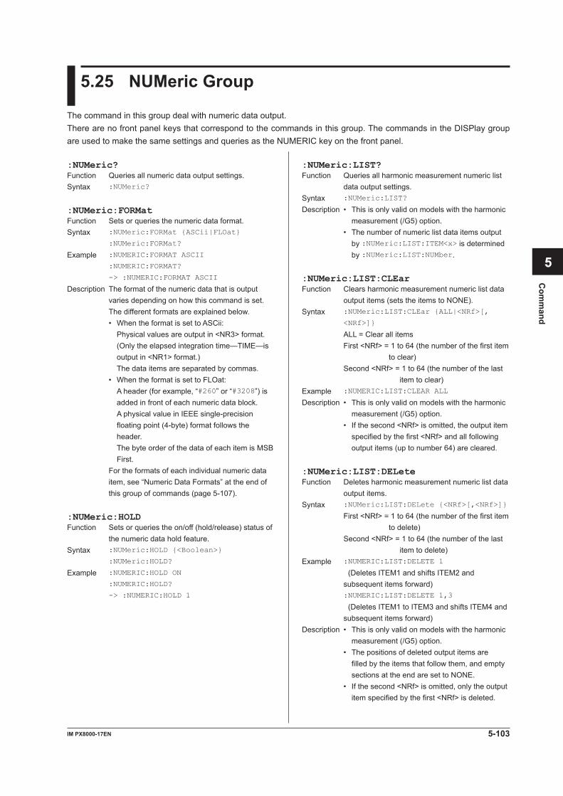
5-103IM PX8000-17EN
Com
mand
1
2
3
4
5
6
App
Index
5.25 NUMeric Group
The command in this group deal with numeric data output.There are no front panel keys that correspond to the commands in this group. The commands in the DISPlay group are used to make the same settings and queries as the NUMERIC key on the front panel.
:NUMeric?Function Queries all numeric data output settings.Syntax :NUMeric?
:NUMeric:FORMatFunction Sets or queries the numeric data format.Syntax :NUMeric:FORMat {ASCii|FLOat}
:NUMeric:FORMat?
Example :NUMERIC:FORMAT ASCII
:NUMERIC:FORMAT?
-> :NUMERIC:FORMAT ASCII
Description The format of the numeric data that is output varies depending on how this command is set. The different formats are explained below.
• When the format is set to ASCii: Physical values are output in <NR3> format. (Only the elapsed integration time—TIME—is output in <NR1> format.) The data items are separated by commas.
• When the format is set to FLOat: A header (for example, “#260” or “#3208”) is added in front of each numeric data block. A physical value in IEEE single-precision floating point (4-byte) format follows the header. The byte order of the data of each item is MSB First.
For the formats of each individual numeric data item, see “Numeric Data Formats” at the end of this group of commands (page 5-107).
:NUMeric:HOLDFunction Sets or queries the on/off (hold/release) status of
the numeric data hold feature.Syntax :NUMeric:HOLD {<Boolean>}
:NUMeric:HOLD?
Example :NUMERIC:HOLD ON
:NUMERIC:HOLD?
-> :NUMERIC:HOLD 1
:NUMeric:LIST?Function Queries all harmonic measurement numeric list
data output settings.Syntax :NUMeric:LIST?
Description • This is only valid on models with the harmonic measurement (/G5) option.
• The number of numeric list data items output by :NUMeric:LIST:ITEM<x> is determined by :NUMeric:LIST:NUMber.
:NUMeric:LIST:CLEarFunction Clears harmonic measurement numeric list data
output items (sets the items to NONE).Syntax :NUMeric:LIST:CLEar {ALL|<NRf>[,
<NRf>]}
ALL = Clear all items First <NRf> = 1 to 64 (the number of the first item
to clear) Second <NRf> = 1 to 64 (the number of the last
item to clear)Example :NUMERIC:LIST:CLEAR ALL
Description • This is only valid on models with the harmonic measurement (/G5) option.
• If the second <NRf> is omitted, the output item specified by the first <NRf> and all following output items (up to number 64) are cleared.
:NUMeric:LIST:DELeteFunction Deletes harmonic measurement numeric list data
output items.Syntax :NUMeric:LIST:DELete {<NRf>[,<NRf>]}
First <NRf> = 1 to 64 (the number of the first item to delete)
Second <NRf> = 1 to 64 (the number of the last item to delete)
Example :NUMERIC:LIST:DELETE 1
(Deletes ITEM1 and shifts ITEM2 and subsequent items forward)
:NUMERIC:LIST:DELETE 1,3
(Deletes ITEM1 to ITEM3 and shifts ITEM4 and subsequent items forward)
Description • This is only valid on models with the harmonic measurement (/G5) option.
• The positions of deleted output items are filled by the items that follow them, and empty sections at the end are set to NONE.
• If the second <NRf> is omitted, only the output item specified by the first <NRf> is deleted.
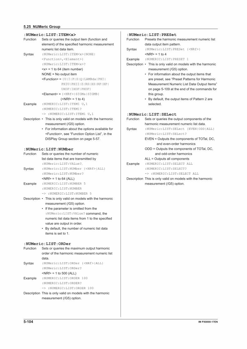
5-104 IM PX8000-17EN
:NUMeric:LIST:ITEM<x>Function Sets or queries the output item (function and
element) of the specified harmonic measurement numeric list data item.
Syntax :NUMeric:LIST:ITEM<x>{NONE|
<Function>,<Element>}
:NUMeric:LIST:ITEM<x>?
<x> = 1 to 64 (item number) NONE = No output item <Function> = {U|I|P|S|Q|LAMBda|PHI|
PHIU|PHII|Z|RS|XS|RP|XP|
UHDF|IHDF|PHDF}
<Element> = {<NRf>|SIGMa|SIGMB} (<NRf> = 1 to 4)
Example :NUMERIC:LIST:ITEM1 U,1
:NUMERIC:LIST:ITEM1?
-> :NUMERIC:LIST:ITEM1 U,1
Description • This is only valid on models with the harmonic measurement (/G5) option.
• For information about the options available for <Function>, see “Function Option List”, in the DISPlay Group section on page 5-57.
:NUMeric:LIST:NUMberFunction Sets or queries the number of numeric
list data items that are transmitted by :NUMeric:LIST:VALue?.
Syntax :NUMeric:LIST:NUMber {<NRf>|ALL}
:NUMeric:LIST:NUMber?
<NRf> = 1 to 64 (ALL)Example :NUMERIC:LIST:NUMBER 5
:NUMERIC:LIST:NUMBER
-> :NUMERIC:LIST:NUMBER 5
Description • This is only valid on models with the harmonic measurement (/G5) option.
• If the parameter is omitted from the :NUMeric:LIST:VALue? command, the numeric list data items from 1 to the specified value are output in order.
• By default, the number of numeric list data items is set to 1.
:NUMeric:LIST:ORDerFunction Sets or queries the maximum output harmonic
order of the harmonic measurement numeric list data.
Syntax :NUMeric:LIST:ORDer {<NRf>|ALL}
:NUMeric:LIST:ORDer?
<NRf> = 1 to 500 (ALL)Example :NUMERIC:LIST:ORDER 100
:NUMERIC:LIST:ORDER?
-> :NUMERIC:LIST:ORDER 100
Description This is only valid on models with the harmonic measurement (/G5) option.
:NUMeric:LIST:PRESetFunction Presets the harmonic measurement numeric list
data output item pattern.Syntax :NUMeric:LIST:PRESet {<NRf>}
<NRf> = 1 to 4Example :NUMERIC:LIST:PRESET 1
Description • This is only valid on models with the harmonic measurement (/G5) option.
• For information about the output items that are preset, see “Preset Patterns for Harmonic Measurement Numeric List Data Output Items” on page 5-109 at the end of the commands for this group.
• By default, the output items of Pattern 2 are selected.
:NUMeric:LIST:SELectFunction Sets or queries the output components of the
harmonic measurement numeric list data.Syntax :NUMeric:LIST:SELect {EVEN|ODD|ALL}
:NUMeric:LIST:SELect?
EVEN = Outputs the components of TOTal, DC, and even-order harmonics
ODD = Outputs the components of TOTal, DC, and odd-order harmonics
ALL = Outputs all componentsExample :NUMERIC:LIST:SELECT ALL
:NUMERIC:LIST:SELECT?
-> :NUMERIC:LIST:SELECT ALL
Description This is only valid on models with the harmonic measurement (/G5) option.
5.25 NUMeric Group
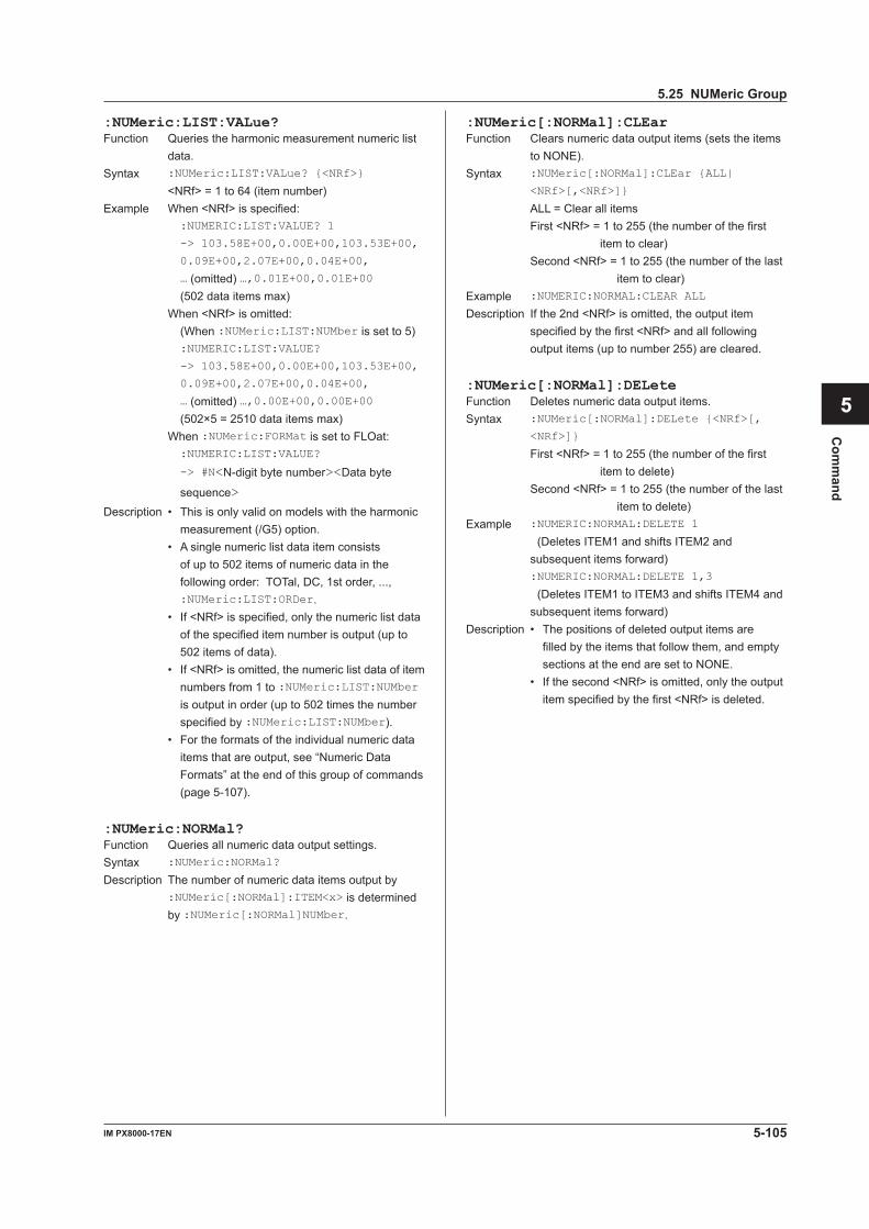
5-105IM PX8000-17EN
Com
mand
1
2
3
4
5
6
App
Index
:NUMeric:LIST:VALue?Function Queries the harmonic measurement numeric list
data.Syntax :NUMeric:LIST:VALue? {<NRf>}
<NRf> = 1 to 64 (item number)Example When <NRf> is specified: :NUMERIC:LIST:VALUE? 1
-> 103.58E+00,0.00E+00,103.53E+00,
0.09E+00,2.07E+00,0.04E+00,
… (omitted) …,0.01E+00,0.01E+00 (502 data items max)
When <NRf> is omitted: (When :NUMeric:LIST:NUMber is set to 5) :NUMERIC:LIST:VALUE?
-> 103.58E+00,0.00E+00,103.53E+00,
0.09E+00,2.07E+00,0.04E+00,
… (omitted) …,0.00E+00,0.00E+00 (502×5 = 2510 data items max)
When :NUMeric:FORMat is set to FLOat: :NUMERIC:LIST:VALUE?
-> #N<N-digit byte number><Data byte
sequence>
Description • This is only valid on models with the harmonic measurement (/G5) option.
• A single numeric list data item consists of up to 502 items of numeric data in the following order: TOTal, DC, 1st order, ..., :NUMeric:LIST:ORDer.
• If <NRf> is specified, only the numeric list data of the specified item number is output (up to 502 items of data).
• If <NRf> is omitted, the numeric list data of item numbers from 1 to :NUMeric:LIST:NUMber is output in order (up to 502 times the number specified by :NUMeric:LIST:NUMber).
• For the formats of the individual numeric data items that are output, see “Numeric Data Formats” at the end of this group of commands (page 5-107).
:NUMeric:NORMal?Function Queries all numeric data output settings.Syntax :NUMeric:NORMal?
Description The number of numeric data items output by :NUMeric[:NORMal]:ITEM<x> is determined by :NUMeric[:NORMal]NUMber.
:NUMeric[:NORMal]:CLEarFunction Clears numeric data output items (sets the items
to NONE).Syntax :NUMeric[:NORMal]:CLEar {ALL|
<NRf>[,<NRf>]}
ALL = Clear all items First <NRf> = 1 to 255 (the number of the first
item to clear) Second <NRf> = 1 to 255 (the number of the last
item to clear)Example :NUMERIC:NORMAL:CLEAR ALL
Description If the 2nd <NRf> is omitted, the output item specified by the first <NRf> and all following output items (up to number 255) are cleared.
:NUMeric[:NORMal]:DELeteFunction Deletes numeric data output items.Syntax :NUMeric[:NORMal]:DELete {<NRf>[,
<NRf>]}
First <NRf> = 1 to 255 (the number of the first item to delete)
Second <NRf> = 1 to 255 (the number of the last item to delete)
Example :NUMERIC:NORMAL:DELETE 1
(Deletes ITEM1 and shifts ITEM2 and subsequent items forward)
:NUMERIC:NORMAL:DELETE 1,3
(Deletes ITEM1 to ITEM3 and shifts ITEM4 and subsequent items forward)
Description • The positions of deleted output items are filled by the items that follow them, and empty sections at the end are set to NONE.
• If the second <NRf> is omitted, only the output item specified by the first <NRf> is deleted.
5.25 NUMeric Group
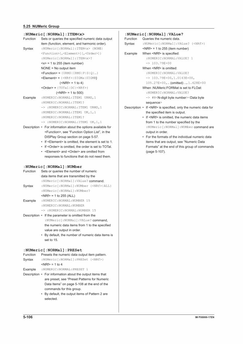
5-106 IM PX8000-17EN
:NUMeric[:NORMal]:ITEM<x>Function Sets or queries the specified numeric data output
item (function, element, and harmonic order).Syntax :NUMeric[:NORMal]:ITEM<x> {NONE|
<Function>[,<Element>][,<Order>]}
:NUMeric[:NORMal]:ITEM<x>?
<x> = 1 to 255 (item number) NONE = No output item <Function> = {URMS|IRMS|P|S|Q|…} <Element> = {<NRf>|SIGMa|SIGMB}
(<NRf> = 1 to 4) <Order> = {TOTal|DC|<NRf>}
(<NRf> = 1 to 500)Example :NUMERIC:NORMAL:ITEM1 URMS,1
:NUMERIC:NORMAL:ITEM1?
-> :NUMERIC:NORMAL:ITEM1 URMS,1
:NUMERIC:NORMAL:ITEM1 UK,1,1
:NUMERIC:NORMAL:ITEM1?
-> :NUMERIC:NORMAL:ITEM1 UK,1,1
Description • For information about the options available for <Function>, see “Function Option List”, in the DISPlay Group section on page 5-57.
• If <Element> is omitted, the element is set to 1. • If <Order> is omitted, the order is set to TOTal. • <Element> and <Order> are omitted from
responses to functions that do not need them.
:NUMeric[:NORMal]:NUMberFunction Sets or queries the number of numeric
data items that are transmitted by the :NUMeric[:NORMal]:VALue? command.
Syntax :NUMeric[:NORMal]:NUMber {<NRf>|ALL}
:NUMeric[:NORMal]:NUMber?
<NRf> = 1 to 255 (ALL)Example :NUMERIC:NORMAL:NUMBER 15
:NUMERIC:NORMAL:NUMBER
-> :NUMERIC:NORMAL:NUMBER 15
Description • If the parameter is omitted from the :NUMeric[:NORMal]:VALue? command, the numeric data items from 1 to the specified value are output in order.
• By default, the number of numeric data items is set to 15.
:NUMeric[:NORMal]:PRESetFunction Presets the numeric data output item pattern.Syntax :NUMeric[:NORMal]:PRESet {<NRf>}
<NRf> = 1 to 4Example :NUMERIC:NORMAL:PRESET 1
Description • For information about the output items that are preset, see “Preset Patterns for Numeric Data Items” on page 5-108 at the end of the commands for this group.
• By default, the output items of Pattern 2 are selected.
:NUMeric[:NORMal]:VALue?Function Queries the numeric data.Syntax :NUMeric[:NORMal]:VALue? {<NRf>}
<NRf> = 1 to 255 (item number)Example When <NRf> is specified:
:NUMERIC:NORMAL:VALUE? 1
-> 103.79E+00
When <NRf> is omitted: :NUMERIC:NORMAL:VALUE?
-> 103.79E+00,1.0143E+00,
105.27E+00,… (omitted) …,1.428E+00 When :NUMeric:FORMat is set to FLOat:
:NUMERIC:NORMAL:VALUE?
-> #N<N-digit byte number><Data byte sequence>
Description • If <NRf> is specified, only the numeric data for the specified item is output.
• If <NRf> is omitted, the numeric data items from 1 to the number specified by the :NUMeric[:NORMal]:NUMber command are output in order.
• For the formats of the individual numeric data items that are output, see “Numeric Data Formats” at the end of this group of commands (page 5-107).
5.25 NUMeric Group
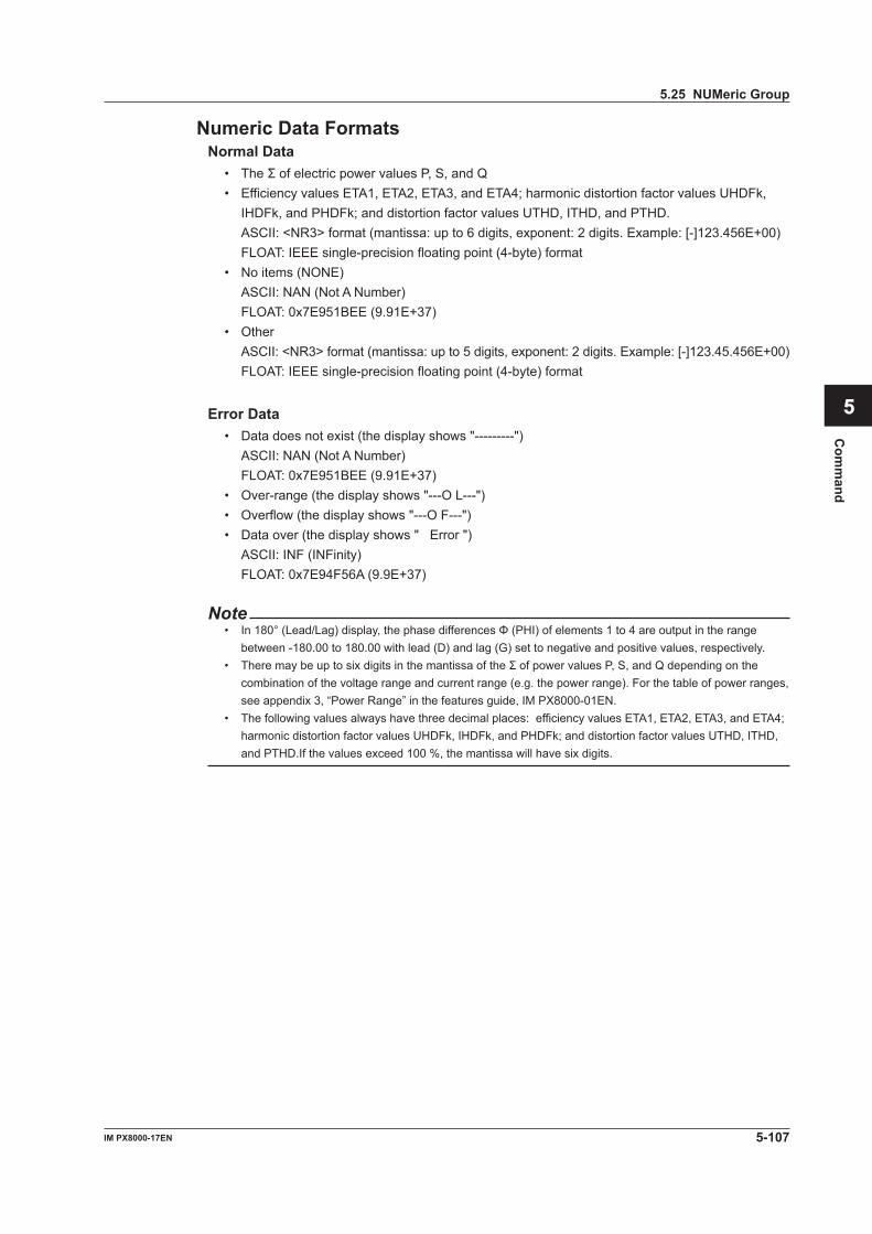
5-107IM PX8000-17EN
Com
mand
1
2
3
4
5
6
App
Index
Numeric Data FormatsNormal Data
• TheΣofelectricpowervaluesP,S,andQ• Efficiency values ETA1, ETA2, ETA3, and ETA4; harmonic distortion factor values UHDFk,
IHDFk, and PHDFk; and distortion factor values UTHD, ITHD, and PTHD. ASCII: <NR3> format (mantissa: up to 6 digits, exponent: 2 digits. Example: [-]123.456E+00) FLOAT: IEEE single-precision floating point (4-byte) format• No items (NONE) ASCII: NAN (Not A Number) FLOAT: 0x7E951BEE (9.91E+37)• Other ASCII: <NR3> format (mantissa: up to 5 digits, exponent: 2 digits. Example: [-]123.45.456E+00) FLOAT: IEEE single-precision floating point (4-byte) format
Error Data• Data does not exist (the display shows "---------") ASCII: NAN (Not A Number) FLOAT: 0x7E951BEE (9.91E+37)• Over-range (the display shows "---O L---")• Overflow (the display shows "---O F---")• Data over (the display shows " Error ") ASCII: INF (INFinity) FLOAT: 0x7E94F56A (9.9E+37)
Note• In180°(Lead/Lag)display,thephasedifferencesΦ(PHI)ofelements1to4areoutputintherange
between -180.00 to 180.00 with lead (D) and lag (G) set to negative and positive values, respectively.• TheremaybeuptosixdigitsinthemantissaoftheΣofpowervaluesP,S,andQdependingonthe
combination of the voltage range and current range (e.g. the power range). For the table of power ranges, see appendix 3, “Power Range” in the features guide, IM PX8000-01EN.
• The following values always have three decimal places: efficiency values ETA1, ETA2, ETA3, and ETA4; harmonic distortion factor values UHDFk, IHDFk, and PHDFk; and distortion factor values UTHD, ITHD, and PTHD.If the values exceed 100 %, the mantissa will have six digits.
5.25 NUMeric Group
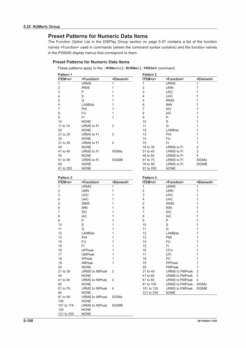
5-108 IM PX8000-17EN
Preset Patterns for Numeric Data ItemsThe Function Option List in the DISPlay Group section on page 5-57 contains a list of the function names <Function> used in commands (where the command syntax contains) and the function names in the PX8000 display menus that correspond to them.
Preset Patterns for Numeric Data ItemsThese patterns apply to the :NUMeric[:NORMal]:PRESet command.
Pattern 1 Pattern 2ITEM<x> <Function> <Element> ITEM<x> <Function> <Element>1 URMS 1 1 URMS 12 IRMS 1 2 UMN 13 P 1 3 UDC 14 S 1 4 UAC 15 Q 1 5 IRMS 16 LAMBda 1 6 IMN 17 PHI 1 7 IDC 18 FU 1 8 IAC 19 FI 1 9 P 110 NONE 10 S 111 to 19 URMS to FI 2 11 Q 120 NONE 12 LAMBda 121 to 29 URMS to FI 3 13 PHI 130 NONE 14 FU 131 to 39 URMS to FI 4 15 FI 140 NONE 16 to 30 URMS to FI 241 to 49 URMS to FI SIGMa 31 to 45 URMS to FI 350 NONE 46 to 60 URMS to FI 451 to 59 URMS to FI SIGMB 61 to 75 URMS to FI SIGMa60 NONE 76 to 90 URMS to FI SIGMB61 to 255 NONE 91 to 255 NONE
Pattern 3 Pattern 4ITEM<x> <Function> <Element> ITEM<x> <Function> <Element>1 URMS 1 1 URMS 12 UMN 1 2 UMN 13 UDC 1 3 UDC 14 UAC 1 4 UAC 15 IRMS 1 5 IRMS 16 IMN 1 6 IMN 17 IDC 1 7 IDC 18 IAC 1 8 IAC 19 P 1 9 P 110 S 1 10 S 111 Q 1 11 Q 112 LAMBda 1 12 LAMBda 113 PHI 1 13 PMI 114 FU 1 14 FU 115 FI 1 15 FI 116 UPPeak 1 16 CFU 117 UMPeak 1 17 CFI 118 IPPeak 1 18 PC 119 IMPeak 1 19 PPPeak 120 NONE 20 PMPeak 121 to 39 URMS to IMPeak 2 21 to 40 URMS to PMPeak 240 NONE 41 to 60 URMS to PMPeak 341 to 59 URMS to IMPeak 3 61 to 80 URMS to PMPeak 460 NONE 81 to 100 URMS to PMPeak SIGMa61 to 79 URMS to IMPeak 4 101 to 120 URMS to PMPeak SIGMB80 NONE 121 to 255 NONE81 to 99 URMS to IMPeak SIGMa100 NONE101 to 119 URMS to IMPeak SIGMB120 NONE121 to 255 NONE
5.25 NUMeric Group
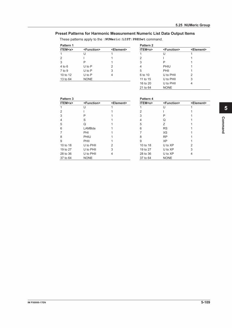
5-109IM PX8000-17EN
Com
mand
1
2
3
4
5
6
App
Index
Preset Patterns for Harmonic Measurement Numeric List Data Output ItemsThese patterns apply to the :NUMeric:LIST:PRESet command.
Pattern 1 Pattern 2ITEM<x> <Function> <Element> ITEM<x> <Function> <Element>1 U 1 1 U 12 I 1 2 I 13 P 1 3 P 14 to 6 U to P 2 4 PHIU 17 to 9 U to P 3 5 PHII 110 to 12 U to P 4 6 to 10 U to PHII 213 to 64 NONE 11 to 15 U to PHII 3
16 to 20 U to PHII 421 to 64 NONE
Pattern 3 Pattern 4ITEM<x> <Function> <Element> ITEM<x> <Function> <Element>1 U 1 1 U 12 I 1 2 I 13 P 1 3 P 14 S 1 4 Q 15 Q 1 5 Z 16 LAMBda 1 6 RS 17 PHI 1 7 XS 18 PHIU 1 8 RP 19 PHII 1 9 XP 110 to 18 U to PHII 2 10 to 18 U to XP 219 to 27 U to PHII 3 19 to 27 U to XP 328 to 36 U to PHII 4 28 to 36 U to XP 437 to 64 NONE 37 to 64 NONE
5.25 NUMeric Group
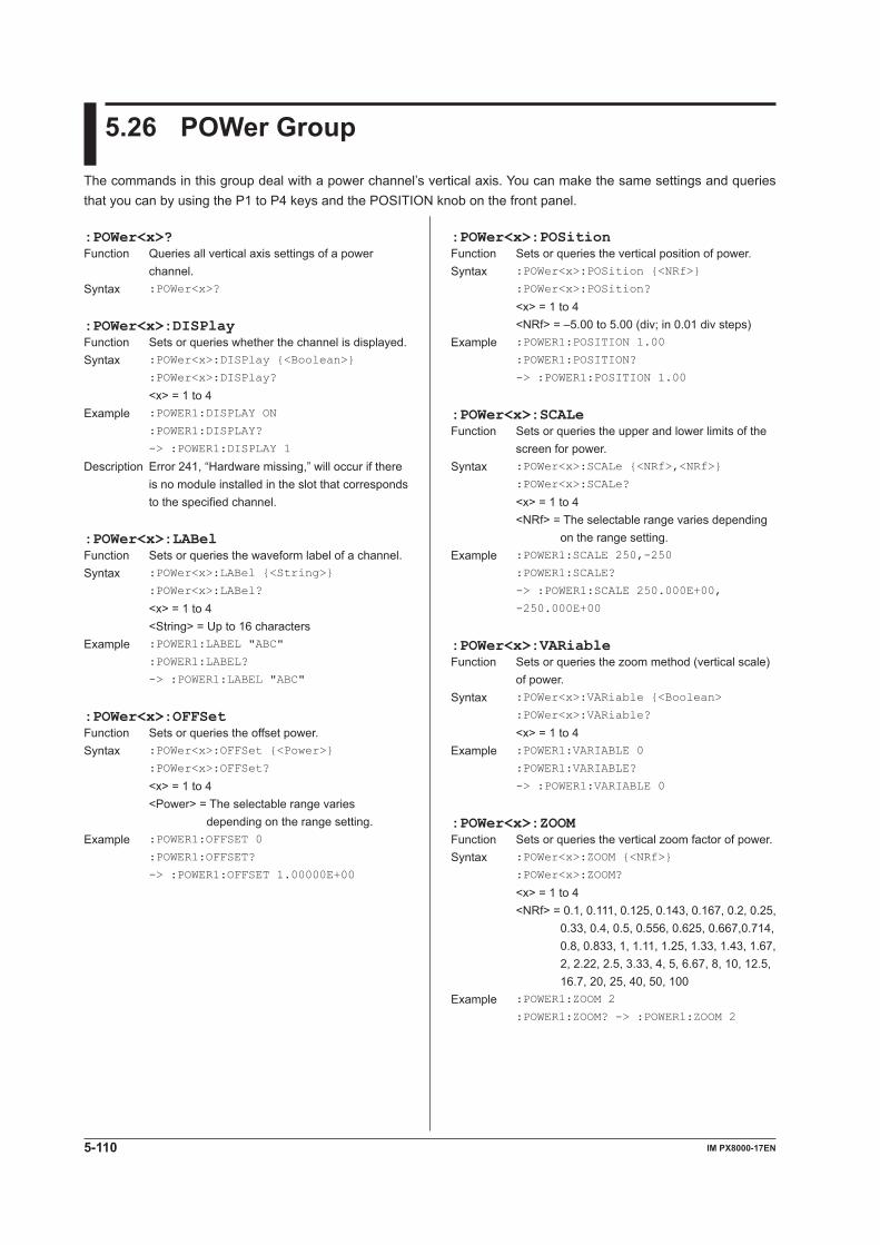
5-110 IM PX8000-17EN
5.26 POWer Group
The commands in this group deal with a power channel’s vertical axis. You can make the same settings and queries that you can by using the P1 to P4 keys and the POSITION knob on the front panel.
:POWer<x>?Function Queries all vertical axis settings of a power
channel.Syntax :POWer<x>?
:POWer<x>:DISPlayFunction Sets or queries whether the channel is displayed.Syntax :POWer<x>:DISPlay {<Boolean>}
:POWer<x>:DISPlay?
<x> = 1 to 4Example :POWER1:DISPLAY ON
:POWER1:DISPLAY?
-> :POWER1:DISPLAY 1
Description Error 241, “Hardware missing,” will occur if there is no module installed in the slot that corresponds to the specified channel.
:POWer<x>:LABelFunction Sets or queries the waveform label of a channel.Syntax :POWer<x>:LABel {<String>}
:POWer<x>:LABel?
<x> = 1 to 4 <String> = Up to 16 charactersExample :POWER1:LABEL "ABC"
:POWER1:LABEL?
-> :POWER1:LABEL "ABC"
:POWer<x>:OFFSetFunction Sets or queries the offset power.Syntax :POWer<x>:OFFSet {<Power>}
:POWer<x>:OFFSet?
<x> = 1 to 4 <Power> = The selectable range varies
depending on the range setting.Example :POWER1:OFFSET 0
:POWER1:OFFSET?
-> :POWER1:OFFSET 1.00000E+00
:POWer<x>:POSitionFunction Sets or queries the vertical position of power.Syntax :POWer<x>:POSition {<NRf>}
:POWer<x>:POSition?
<x> = 1 to 4 <NRf> = –5.00 to 5.00 (div; in 0.01 div steps)Example :POWER1:POSITION 1.00
:POWER1:POSITION?
-> :POWER1:POSITION 1.00
:POWer<x>:SCALeFunction Sets or queries the upper and lower limits of the
screen for power.Syntax :POWer<x>:SCALe {<NRf>,<NRf>}
:POWer<x>:SCALe?
<x> = 1 to 4 <NRf> = The selectable range varies depending
on the range setting.Example :POWER1:SCALE 250,-250
:POWER1:SCALE?
-> :POWER1:SCALE 250.000E+00,
-250.000E+00
:POWer<x>:VARiableFunction Sets or queries the zoom method (vertical scale)
of power.Syntax :POWer<x>:VARiable {<Boolean>
:POWer<x>:VARiable?
<x> = 1 to 4Example :POWER1:VARIABLE 0
:POWER1:VARIABLE?
-> :POWER1:VARIABLE 0
:POWer<x>:ZOOMFunction Sets or queries the vertical zoom factor of power.Syntax :POWer<x>:ZOOM {<NRf>}
:POWer<x>:ZOOM?
<x> = 1 to 4 <NRf> = 0.1, 0.111, 0.125, 0.143, 0.167, 0.2, 0.25,
0.33, 0.4, 0.5, 0.556, 0.625, 0.667,0.714, 0.8, 0.833, 1, 1.11, 1.25, 1.33, 1.43, 1.67, 2, 2.22, 2.5, 3.33, 4, 5, 6.67, 8, 10, 12.5, 16.7, 20, 25, 40, 50, 100
Example :POWER1:ZOOM 2
:POWER1:ZOOM? -> :POWER1:ZOOM 2
5-111IM PX8000-17EN
Com
mand
1
2
3
4
5
6
App
Index
5.27 RECall Group
The command in this group deal with storing and recalling of settings. You can perform the same operations and make the same settings and queries that you can by pressing the UTILITY key on the front panel and then using Recall Exec on the Setup Data Store/Recall menu.
:RECall:SETup<x>:EXECuteFunction Recalls setup data from an internal memory area.Syntax :RECall:SETup<x>:EXECute
<x> = 1 to 16Example :RECALL:SETUP1:EXECUTE
Description If you specify an area that does not contain setup data, an error occurs.
5-112 IM PX8000-17EN
5.28 SEARch Group
The commands in this group deal with searching for and extracting patterns from acquired waveforms. You can perform the same operations and make the same settings and queries that you can by using the SHIFT+ZOOM keys on the front panel.If the selectable range of the time axis is “<NRf> = –5 to 5div,” the selectable range varies depending on settings such as the record length. For details, see “Selectable Range of Cursor Positions” under “Notes about Cursor Measurement” in chapter 15 of IM PX8000-01EN.
:SEARch:EDGE:SLOPeFunction Sets or queries the edge polarity for when the
edge search is performed on traces other than logic traces.
Syntax :SEARch:EDGE:SLOPe {BISLope|FALL|
RISE}
:SEARch:EDGE:SLOPe?
Example :SEARCH:EDGE:SLOPE RISE
:SEARCH:EDGE:SLOPE?
-> :SEARCH:EDGE:SLOPE RISE
:SEARch:EDGE:SOURceFunction Sets or queries the trace to perform the edge
search on.Syntax :SEARch:EDGE:SOURce {<NRf>|P<y>}
:SEARch:EDGE:SOURce?
<NRf> = 1 to 8 <y> = 1 to 4Example :SEARCH:EDGE:SOURCE 1
:SEARCH:EDGE:SOURCE?
-> :SEARCH:EDGE:SOURCE 1
Description If no module is installed, you cannot select the edge search.
:SEARch:EPOint (End POint)Function Sets or queries the search end position.Syntax :SEARch:EPOint {<NRf>}
:SEARch:EPOint?
<NRf> = –5 to 5div (the resolution depends on the measurement length)
Example :SEARCH:EPOINT 3
:SEARCH:EPOINT?
-> :SEARCH:EPOINT 3.000000000000
:SEARch:EXECuteFunction Executes the search.Syntax :SEARch:EXECute
:SEARch?Function Queries all search settings.Syntax :SEARch?
:SEARch:ABORtFunction Aborts the search.Syntax :SEARch:ABORt
Example :SEARCH:ABORT
:SEARch:EDGE?Function Queries all edge search settings.Syntax :SEARch:EDGE?
:SEARch:EDGE:COUNtFunction Sets or queries the edge search count.Syntax :SEARch:EDGE:COUNt {<NRf>}
:SEARch:EDGE:COUNt?
<NRf> = 1 to 1000000Example :SEARCH:EDGE:COUNT 100
:SEARCH:EDGE:COUNT?
-> :SEARCH:EDGE:COUNT 100
:SEARch:EDGE:HYSTeresisFunction Sets or queries the edge search determination-
level hysteresis.Syntax :SEARch:EDGE:HYSTeresis {HIGH|LOW|
MIDDle}
:SEARch:EDGE:HYSTeresis?
Example :SEARCH:EDGE:HYSTERESIS LOW
:SEARCH:EDGE:HYSTERESIS?
-> :SEARCH:EDGE:HYSTERESIS LOW
Description This setting is valid if the channel that is being searched is not a logic channel.
:SEARch:EDGE:LEVElFunction Sets or queries the edge search determination
level.Syntax :SEARch:EDGE:LEVEl {<Voltage>|
<Current>|<NRf>}
:SEARch:EDGE:LEVEl?
Example :SEARCH:EDGE:LEVEL 2
:SEARCH:EDGE:LEVEL?
-> :SEARCH:EDGE:LEVEL 2.00000E+00
5-113IM PX8000-17EN
Com
mand
1
2
3
4
5
6
App
Index
:SEARch:MAG<x>Function Sets or queries a zoom waveform magnification.Syntax :SEARch:MAG<x> {<NRf>}
:SEARch:MAG<x>?
<x> = 1, 2 <NRf> = 2 to 200000000Example :SEARCH:MAG1 1000
:SEARCH:MAG1? -> :SEARCH:MAG1 1000.0
Description This command is valid when the PX8000 is using an external clock. When the PX8000 is using the internal clock, use the :SEARch:TDIV<x> command to set the magnification.
:SEARch:POSition<x>Function Sets or queries the position of a zoom box.Syntax :SEARch:POSition<x> {<NRf>}
:SEARch:POSition<x>?
<x> = 1, 2 <NRf> = –5 to +5 divExample :SEARCH:POSITION1 -0.7219
:SEARCH:POSITION1?
-> :SEARCH:POSITION1 -0.721900000000
:SEARch:SELectFunction Sets the search point that is displayed on the
zoom window, and queries the zoom position of that search point.
Syntax :SEARch:SELect {<NRf>|MAXimum}
:SEARch:SELect?
<NRf> = 1 to 5000Example :SEARCH:SELECT 4
:SEARCH:SELECT?
-> :SEARCH:SELECT -0.721900000000
Description The string “NAN” is returned if the search could not retrieve a position.
:SEARch:SELect? MAXimumFunction Queries the maximum save number, which is the
number that is attached to the last position that the search retrieved.
Syntax :SEARch:SELect? MAXimum
Example :SEARCH:SELECT? MAXIMUM
-> :SEARCH:SELECT 5
Description The string “NAN” is returned if the search could not retrieve a position.
:SEARch:SPOint (Start POint)Function Sets or queries the search start position.Syntax :SEARch:SPOint {<NRf>}
:SEARch:SPOint?
<NRf> = –5 to 5div (the resolution depends on the measurement length)
Example :SEARCH:SPOINT -5
:SEARCH:SPOINT?
-> :SEARCH:SPOINT -5.000000000000
:SEARch:TDIV<x>Function Sets or queries a zoom waveform T/DIV value.Syntax :SEARch:TDIV<x> {<Time>|HOUR1|HOUR2|
HOUR3|HOUR4|HOUR5|HOUR6|HOUR7|HOUR8|
HOUR9|HOUR10|HOUR12|DAY1|DAY2|DAY3}
:SEARch:TDIV<x>?
<x> = 1, 2 (sets the target zoom box) <Time> = the same as the T/Div settingExample :SEARCH:TDIV1 0.01
:SEARCH:TDIV1?
-> :SEARCH:TDIV1 10.00E-03
Description This command is valid when the PX8000 is using the internal clock. When the PX8000 is using an external clock, use the :SEARch:MAG<x> command to set the magnification.
:SEARch:TIME?Function Queries all time search settings.Syntax :SEARch:TIME?
:SEARch:TIME:TIMEFunction Sets or queries the time of the time search.Syntax :SEARch:TIME:TIME {<NRf>,<NRf>,
<NRf>,<NRf>,<NRf>,<NRf>,<NRf>}
:SEARch:TIME:TIME?
<NRf> = 2000 or greater (year) <NRf> = 1 to 12 (month) <NRf> = 1 to 31 (day) <NRf> = 0 to 23 (hour) <NRf> = 0 to 59 (minute) <NRf> = 0 to 59 (second) <NRf> = 0 to 999999 (microsecond)Example :SEARCH:TIME:TIME 2010,1,1,0,0,0,0
:SEARCH:TIME:TIME?
-> :SEARCH:TIME:TIME 2010,1,1,0,0,0,0
Description The initial value is the reference time of the waveform that is displayed when you open the menu. If there are no history waveforms or if the menu is not open, the initial value is 00:00:00:00 on January 1, 2010.
:SEARch:TWINdow (Target WINdow)Function Sets or queries the window that search results
will be displayed in.Syntax SEARch:TWINdow {Z1|Z2}
SEARch:TWINdow?
Example :SEARCH:TWINDOW Z1
:SEARCH:TWINDOW?
-> :SEARCH:TWINDOW Z1
:SEARch:TYPEFunction Sets or queries the search type.Syntax :SEARch:TYPE {EDGE|TIME}
:SEARch:TYPE?
Example :SEARCH:TYPE EDGE
:SEARCH:TYPE? -> :SEARCH:TYPE EDGE
5.28 SEARch Group

5-114 IM PX8000-17EN
5.29 SELFtest Group
The commands in this group deal with self-test. You can perform the same operations that you can by pressing the UTILITY key on the front panel and using the Self Test menu.
:SELFtest:CTEMperature? (Cpu TEMperature)Function Returns the CPU temperature.Syntax :SELFtest:CTEMperature?
Example :SELFtest:CTEMperature?
-> :SELFtest:CTEMperature 40.0
:SELFtest:KEYBoardFunction Controls the front panel key test mode.Syntax :SELFtest:KEYBoard {<Boolean>}
Description 1: Switches to key test mode. 0: Exits from key test mode.
:SELFtest:MEMory:ACQuire:EXECute?Function Executes an acquisition memory test.Syntax :SELFtest:MEMory:ACQuire:EXECute?
Description Executes a memory tests and returns the results. Return value
Bit 7 6 5 4 3 2 1 0
AcqMemory1 Error.(An error was detected in the AcqFPGA1 memory.)AcqMemory2 Error.(An error was detected in the AcqFPGA2 memory.)AcqMemory3 Error.(An error was detected in the AcqFPGA3 memory.)AcqMemory4 Error.(An error was detected in the AcqFPGA4 memory.)PCIMemory1 Error.(An error was detected in the PCI FPGA memory.)
:SELFtest:MEMory:SYSTem:EXECute?Function Executes an system memory test.Syntax :SELFtest:MEMory:SYSTem:EXECute?
Description Executes a memory tests and returns the results. Return value 0: Test OK A value other than 0: Not OK
:SELFtest:MEMory:SRAM:EXECute?Function Executes an backup memory test.Syntax :SELFtest:MEMory:SRAM:EXECute?
Description Executes a memory tests and returns the results. Return value 0: Test OK A value other than 0: Not OK
5-115IM PX8000-17EN
Com
mand
1
2
3
4
5
6
App
Index
5.30 SNAP Group
The command in this group is used to take snapshots. You can execute the same operation that you can by using the SNAPSHOT key on the front panel.
:SNAPFunction Takes a snapshot.Syntax :SNAP
Example :SNAP
5-116 IM PX8000-17EN
5.31 SSTart Group
The commands in this group deal with executing the single start operation. These commands set the trigger mode to Single and start waveform acquisition.
:SSTartFunction Executes the single start operation.Syntax :SSTart
Example :SSTART
:SSTart?Function Executes the single start operation and waits for
its completion by using a timeout valuer.Syntax :SSTart? {<NRf>}
Example :SSTart? 100
Description <NRf> = 1 to 36000 (timeout value in 100 ms steps; start and wait)
–36000 to –1 (timeout value in 100 ms steps; wait without starting)

5-117IM PX8000-17EN
Com
mand
1
2
3
4
5
6
App
Index
5.32 STARt Group
The command in this group is used to start waveform acquisition. You can execute the same operation that you can by using the START/STOP key on the front panel.
:STARtFunction Starts waveform acquisition.Syntax :STRTt
Example :START

5-118 IM PX8000-17EN
5.33 STATus Group
The commands in this group are used to make settings and queries related to the status report. There are no front panel keys that correspond to the commands in this group. For information about status reports, see chapter 6.
:STATus?Function Queries all the settings for the communication
status feature.Syntax :STATus?
:STATus:CONDition?Function Queries the contents of the condition register.Syntax :STATus:CONDition?
Example :STATUS:CONDITION? -> 16
Description For details on how to use the :STATus:CONDition? command to synchronize the PX8000, see page 4-9.
:STATus:EESEFunction Sets or queries the extended event enable
register.Syntax :STATus:EESE <Register>
:STATus:EESE?
<Register> = 0 to 65535Example :STATUS:EESE #B00000000
:STATUS:EESE? -> :STATUS:EESE 0
:STATus:EESR?Function Queries the contents of the extended event
register and clears the register.Syntax :STATus:EESR?
Example :STATUS:EESR? -> 0
:STATus:ERRor?Function Queries the error code and message of the last
error that has occurred.Syntax :STATus:ERRor?
Description • If no errors have occurred, 0,"No error" is returned.
• You can use the :STATus:QMESsage command to specify whether the message is included.
:STATus:FILTer<x>Function Sets or queries the transition filter.Syntax :STATus:FILTer<x> {RISE|FALL|BOTH|
NEVer}
:STATus:FILTer<x>?
<x> = 1 to 16Description Set how each bit in the condition register must
change to trigger the setting of an event. If you specify RISE, a change from 0 to 1 triggers the setting of an event.
:STATus:QENableFunction Sets or queries whether messages other than
errors will be stored to the error queue (ON) or not (OFF).
Syntax :STATus:QENable {<Boolean>}
:STATus:QENable?
Example :STATUS:QENABLE ON
:STATUS:QENABLE?
-> :STATUS:QENABLE 1
:STATus:QMESsageFunction Sets or queries whether message information will
be attached to the response to the :STAT:ERR? query (ON) or not (OFF).
Syntax :STATus:QMESsage {<Boolean>}
:STATus:QMESsage?
Example :STATUS:QMESSAGE ON
:STATUS:QMESSAGE?
-> :STATUS:QMESSAGE 1

5-119IM PX8000-17EN
Com
mand
1
2
3
4
5
6
App
Index
5.34 STOP Group
The command in this group is used to stop waveform acquisition. You can execute the same operation that you can by using the START/STOP key on the front panel.
:STOPFunction Stops waveform acquisition.Syntax :STOP
5-120 IM PX8000-17EN
5.35 STORe Group
The commands in this group deal with saving setup data. You can perform the same operations and make the same settings that you can by using the UTILITY key on the front panel and then using the Setup Data Store/Recall menu.
:STORe?Function Queries all the information related to setup data
in the internal memory.Syntax :STORe?
:STORe:SETup<x>?Function Queries information about the setup data in the
specified location of the internal memory.Syntax :STORe:SETup<x>?
<x> = 1 to 16
:STORe:SETup<x>:CLEarFunction Clear the setup data that is stored to the specified
location in the internal memory.Syntax :STORe:SETup<x>:CLEar
<x> =1 to 16Example :STORE:SETUP1:CLEAR
:STORe:SETup<x>:COMMentFunction Sets or queries the comment for the setup data
that is stored to the specified location in the internal memory.
Syntax :STORe:SETup<x>:COMMent {<String>}
:STORe:SETup<x>:COMMent?
<x> = 1 to 16 <String> = Up to 14 charactersExample :STORE:SETUP1:COMMENT "ABCD"
:STORE:SETUP1:COMMENT?
-> :STORE:SETUP1:COMMENT "ABCD"
:STORe:SETup<x>:DATE?Function Queries the date and time of the setup data that
is stored to the specified location in the internal memory.
Syntax :STORe:SETup<x>:DATE?
<x> = 1 to 16Example :STORE:SETUP1:DATE?
-> :STORE:SETUP1:
DATE "2014/01/01 09:44:02"
Description This command returns “No Valid Data” if no setup data is stored in the specified location.
:STORe:SETup<x>:EXECuteFunction Saves setup data to the specified location in the
internal memory.Syntax :STORe:SETup<x>:EXECute
<x> = 1 to 16Example :STORE:SETUP1:EXECUTE
5-121IM PX8000-17EN
Com
mand
1
2
3
4
5
6
App
Index
5.36 SYSTem Group
The commands in this group deal with the system. You can execute the same operation that you can by using the UTILITY key on the front panel.
:SYSTem?Function Queries all system settings.Syntax :SYSTem?
:SYSTem:CLICkFunction Sets or queries whether click sounds are
produced.Syntax :SYSTem:CLICk {<Boolean>}
:SYSTem:CLICk?
Example :SYSTEM:CLICK ON
:SYSTEM:CLICK? -> :SYSTEM:CLICK 1
:SYSTem:CLOCk?Function Queries all date/time settings.Syntax :SYSTem:CLOCk?
:SYSTem:CLOCk:DATEFunction Sets or queries the date.Syntax :SYSTem:CLOCk:DATE <String>
:SYSTem:CLOCk:DATE?
<String> = YYYY/MM/DD Specify the year according to the Gregorian
calendar. YYYY: 2000 to 2099
Example :SYSTEM:CLOCK:DATE "2014/01/01"
:SYSTEM:CLOCK:DATE?
-> :SYSTEM:CLOCK:DATE "2014/01/01"
Description Regardless of the setting that you have made using the :SYSTem:CLOCk:FORMat command, this command returns responses in the format shown above.
:SYSTem:CLOCk:FORMatFunction Sets or queries the date format.Syntax :SYSTem:CLOCk:FORMat {<NRf>}
:SYSTem:CLOCk:FORMat?
<NRf> = 1 to 4Example :SYSTEM:CLOCK:FORMAT 1
:SYSTEM:CLOCK:FORMAT?
-> :SYSTEM:CLOCK:FORMAT 1
Description This command specifies the display format of the date. (The communication response format of the date is fixed.)
1: Year/month (number)/day 2: Day/month (number)/year 3: Day-month (English abbreviation)-year (last
two digits) 4: Day month (English abbreviation) year
:SYSTem:CLOCk:MODEFunction Sets or queries whether the date and time are
displayed.Syntax :SYSTem:CLOCk:MODE {<Boolean>}
:SYSTem:CLOCk:MODE?
Example :SYSTEM:CLOCK:MODE ON
:SYSTEM:CLOCK:MODE?
-> :SYSTEM:CLOCK:MODE 1
:SYSTem:CLOCk:SNTP?Function Queries all SNTP settings.Syntax :SYSTem:CLOCk:SNTP?
:SYSTem:CLOCk:SNTP:EXECuteFunction Uses SNTP to set the date and time.Syntax :SYSTem:CLOCk:SNTP:EXECute
Example :SYSTEM:CLOCK:SNTP:EXECUTE
:SYSTem:CLOCk:SNTP:GMTTimeFunction Sets or queries the time difference from GMT
when SNTP is being used.Syntax :SYSTem:CLOCk:SNTP:
GMTTime {<String>}
:SYSTem:CLOCk:SNTP:GMTTime?
<String> = HH:MM (–12:00 to 13:00)Example :SYSTEM:CLOCK:SNTP:GMTTIME "09:00"
:SYSTEM:CLOCK:SNTP:GMTTIME?
-> :SYSTEM:CLOCK:SNTP:
GMTTIME "09:00"
:SYSTem:CLOCk:TIMEFunction Sets or queries the time.Syntax :SYSTem:CLOCk:TIME <String>
:SYSTem:CLOCk:TIME?
<String> = HH:MM:SS HH can be set to a value from 0 to 23.Example :SYSTEM:CLOCK:TIME "10:00:00"
:SYSTEM:CLOCK:TIME?
-> :SYSTEM:CLOCK:TIME "10:00:00"
:SYSTem:CLOCk:TYPEFunction Sets or queries whether the date and time are set
manually or by using SNTP.Syntax :SYSTem:CLOCk:TYPE {MANual|SNTP}
:SYSTem:CLOCk:TYPE?
Example :SYSTEM:CLOCK:TYPE MANUAL
:SYSTEM:CLOCK:TYPE?
-> :SYSTEM:CLOCK:TYPE MANUAL
5-122 IM PX8000-17EN
:SYSTem:IRIG:IMPedanceFunction Sets or queries the input impedance for
synchronizing the time through IRIG signals.Syntax :SYSTem:IRIG:IMPedance {<NRf>}
:SYSTem:IRIG:IMPedance?
<NRf> = 50 or 5000Example :SYSTEM:IRIG:IMPEDANCE 50
:SYSTEM:IRIG:IMPEDANCE?
-> :SYSTEM:IRIG:IMPEDANCE 50
Description This command is valid on models with the /C20 option.
:SYSTem:IRIG:MODulationFunction Sets or queries the IRIG modulation type for
synchronizing the time through IRIG signals.Syntax :SYSTem:IRIG:MODulation {AM|PWCode}
:SYSTem:IRIG:MODulation?
Example :SYSTEM:IRIG:MODULATION AM
:SYSTEM:IRIG:MODULATION?
-> :SYSTEM:IRIG:MODULATION AM
Description This command is valid on models with the /C20 option.
:SYSTem:KEYProtect?Function Queries all key lock settings.Syntax :SYSTem:KEYProtect?
:SYSTem:KEYProtect:EPASsword (Enter PASsword)Function Enters the password to release the key lock.Syntax :SYSTem:KEYProtect:
EPASsword {<String>}
<String> = Up to 8 charactersExample :SYSTEM:KEYPROTECT:EPASSWORD "ABC"
Description This command is valid when the keys are locked, a password is required to release the key lock, and a password has been set.
:SYSTem:KEYProtect:MODEFunction Sets or queries whether the keys are locked.Syntax :SYSTem:KEYProtect:MODE {<Boolean>}
:SYSTem:KEYProtect:MODE?
Example :SYSTEM:KEYPROTECT:MODE ON
:SYSTEM:KEYPROTECT:MODE?
-> :SYSTEM:KEYPROTECT:MODE 1
Description The key lock status is retained even when the PX8000 is restarted.
:SYSTem:KEYProtect:RTYPe (Release TYPe)Function Sets or queries how to release the key lock.Syntax :SYSTem:KEYProtect:RTYPe {KEY|
PASSword}
:SYSTem:KEYProtect:RTYPe?
Example :SYSTEM:KEYPROTECT:RTYPE PASSWORD
:SYSTEM:KEYPROTECT:RTYPE?
-> :SYSTEM:KEYPROTECT:RTYPE PASSWORD
:SYSTem:CRMode (Cursor Read Mode)Function Sets or queries the mode used to read vertical,
marker, and degree cursor values.Syntax :SYSTem:CRMode {DISPlay|ACQuisition}
:SYSTem:CRMode?
Example :SYSTEM:CRMODE DISPLAY
:SYSTEM:CRMODE?
-> :SYSTEM:CRMODE DISPLAY
:SYSTem:DFLow?Function Queries all data display settings for low frequency
input (no input).Syntax :SYSTem:DFLow?
:SYSTem:DFLow:AUXiliaryFunction Sets or queries the AUX data display method
for when the AUX module is not receiving pulse input.
Syntax :SYSTem:DFLow:AUXiliary {ZERO|ERRor}
:SYSTem:DFLow:AUXiliary?
Example :SYSTEM:DFLOW:AUXILIARY ERROR
:SYSTEM:DFLOW:AUXILIARY?
-> :SYSTEM:DFLOW:AUXILIARY ERROR
:SYSTem:DFLow:FREQuencyFunction Sets or queries the AUX data display method for
when a power measurement element is receiving low frequency input (no input).
Syntax :SYSTem:DFLow:FREQuency {ZERO|ERRor}
:SYSTem:DFLow:FREQuency?
Example :SYSTEM:DFLOW:FREQUENCY ERROR
:SYSTEM:DFLOW:FREQUENCY?
-> :SYSTEM:DFLOW:FREQUENCY ERROR
:SYSTem:IRIG?Function Queries all IRIG settings.Syntax :SYSTem:IRIG?
:SYSTem:IRIG:FORMatFunction Sets or queries the IRIG format for synchronizing
the time through IRIG signals.Syntax :SYSTem:IRIG:FORMat {A|B}
:SYSTem:IRIG:FORMat?
Example :SYSTEM:IRIG:FORMAT A
:SYSTEM:IRIG:FORMAT?
-> :SYSTEM:IRIG:FORMAT A
Description This command is valid on models with the /C20 option.
5.36 SYSTem Group
5-123IM PX8000-17EN
Com
mand
1
2
3
4
5
6
App
Index
:SYSTem:KEYProtect:SPASsword (Set PASsword)Function Sets the password that is used to release the key
lock.Syntax :SYSTem:KEYProtect:
SPASsword {<String>}
<String> = Up to 8 charactersExample :SYSTEM:KEYPROTECT:SPASSWORD "ABC"
Description Send the command :SYSTem:KEYProtect:SPASsword "" to reset the password.
:SYSTem:KEYProtect:TYPEFunction Sets or queries which keys will be locked.Syntax :SYSTem:KEYProtect:TYPE {ALL|ESTart}
:SYSTem:KEYProtect:TYPE?
Example :SYSTEM:KEYPROTECT:TYPE ESTART
:SYSTEM:KEYPROTECT:TYPE?
-> :SYSTEM:KEYPROTECT:TYPE ESTART
:SYSTem:KEYResponseFunction Sets or queries the response time of the START/
STOP key.Syntax :SYSTem:KEYResponse {QUICK|SEC1}
:SYSTem:KEYResponse?
Example :SYSTEM:KEYRESPONSE SEC1
:SYSTEM:KEYRESPONSE?
-> :SYSTEM:KEYRESPONSE SEC1
:SYSTem:LANGuageFunction Sets or queries the message language.Syntax :SYSTem:LANGuage {JAPANese|ENGLish|
GERMan}
:SYSTem:LANGuage?
Example :SYSTEM:LANGUAGE ENGLISH
:SYSTEM:LANGUAGE?
-> :SYSTEM:LANGUAGE ENGLISH
:SYSTem:LCD?Function Queries all LCD settings.Syntax :SYSTem:LCD?
:SYSTem:LCD:AUTO?Function Queries all the settings for the feature that
automatically turns off the backlight.Syntax :SYSTem:LCD:AUTO?
:SYSTem:LCD:AUTO:MODEFunction Sets or queries whether the feature that
automatically turns off the backlight is on.Syntax :SYSTem:LCD:AUTO:MODE {<Boolean>}
:SYSTem:LCD:AUTO:MODE?
Example :SYSTEM:LCD:AUTO:MODE ON
:SYSTEM:LCD:AUTO:MODE?
-> :SYSTEM:LCD:AUTO:MODE 1
:SYSTem:LCD:AUTO:TIMEFunction Sets or queries the amount of time until the
backlight is turned off.Syntax :SYSTem:LCD:AUTO:TIME {<NRf>}
:SYSTem:LCD:AUTO:TIME?
<NRf> = 1 to 60 (minute)Example :SYSTEM:LCD:AUTO:TIME 10
:SYSTEM:LCD:AUTO:TIME?
-> :SYSTEM:LCD:AUTO:TIME 10
:SYSTem:LCD:BRIGhtnessFunction Sets or queries the LCD brightness.Syntax :SYSTem:LCD:BRIGhtness {<NRf>}
:SYSTem:LCD:BRIGhtness?
<NRf> = 1 to 10Example :SYSTEM:LCD:BRIGHTNESS 3
:SYSTEM:LCD:BRIGHTNESS?
-> :SYSTEM:LCD:BRIGHTNESS 3
:SYSTem:LCD:MODEFunction Sets or queries whether the backlight is on.Syntax :SYSTem:LCD:MODE {<Boolean>}
:SYSTem:LCD:MODE?
Example :SYSTEM:LCD:MODE ON
:SYSTEM:LCD:MODE?
-> :SYSTEM:LCD:MODE 1
:SYSTem:MLANguageFunction Sets or queries the menu language.Syntax :SYSTem:MLANguage {JAPANese|ENGLish|
GERMan}
:SYSTem:MLANguage?
Example :SYSTEM:MLANGUAGE ENGLISH
:SYSTEM:MLANGUAGE?
-> :SYSTEM:MLANGUAGE ENGLISH
:SYSTem:OVERviewFunction Displays the system information.Syntax :SYSTem:OVERview
Example :SYSTEM:OVERVIEW
:SYSTem:PACTionFunction Sets or queries whether the action mode will be
enabled when the PX8000 turns on (ON) or not (OFF).
Syntax :SYSTem:PACTion {<Boolean>}
:SYSTem:PACTion?
Example :SYSTEM:PACTION ON
:SYSTEM:PACTION?
-> :SYSTEM:PACTION 1
5.36 SYSTem Group
5-124 IM PX8000-17EN
:SYSTem:PSTartFunction Sets or queries whether waveform acquisition will
be started when the PX8000 turns on (ON) or not (OFF).
Syntax :SYSTem:PSTart {<Boolean>}
:SYSTem:PSTart?
Example :SYSTEM:PSTART ON
:SYSTEM:PSTART? -> :SYSTEM:PSTART 1
:SYSTem:RCMode (Remote Control Mode)Function Sets or queries whether remote signals to stop
measurements will be ignored (ON) or not (OFF).Syntax :SYSTem:RCMode {<Boolean>}
:SYSTem:RCMode?
Example :SYSTEM:RCMODE ON
:SYSTEM:RCMODE? -> :SYSTEM:RCMODE 1
:SYSTem:SCALefontFunction Sets or queries the font size that is used for
waveform labels and scale values.Syntax :SYSTem:SCALefont {SMALl|LARGe}
:SYSTem:SCALefont?
Example :SYSTEM:SCALEFONT SMALL
:SYSTEM:SCALEFONT?
-> :SYSTEM:SCALEFONT SMALL
Description Even if you specify LARGe with this command, depending on the display conditions, the SMALl font may be displayed.
:SYSTem:SOITem (Scale On ITem)Function Sets or queries which scales are displayed.Syntax :SYSTem:SOITem {ALL|TSCale}
:SYSTem:SOITem?
Example :SYSTEM:SOITEM ALL
:SYSTEM:SOITEM?
-> :SYSTEM:SOITEM ALL
:SYSTem:STORage:FORMat:EXECuteFunction Formats the specified medium. This is an overlap
command.Syntax :SYSTem:STORage:FORMat:EXECute
Example :SYSTEM:STORAGE:FORMAT:EXECUTE
:SYSTem:STORage:MEDiaFunction Sets or queries the medium that you want to
format.Syntax :SYSTem:STORage:MEDia {SD|UUSB|LUSB}
:SYSTem:STORage:MEDia?
Example :SYSTEM:STORAGE:MEDIA SD
:SYSTEM:STORAGE:MEDIA?
-> :SYSTEM:STORAGE:MEDIA SD
Description SD: SD memory card UUSB, LUSB: USB storage medium
:SYSTem:TSYNchro (Time SYNchronization)Function Sets or queries the time synchronization.Syntax :SYSTem:TSYNchro {IRIG|OFF}
:SYSTem:TSYNchro?
Example :SYSTEM*TSYNCHRO IRIG
:SYSTEM*TSYNCHRO?
-> :SYSTEM*TSYNCHRO IRIG
Description This command is valid on models with the /C20 option.
:SYSTem:USBKeyboardFunction Sets or queries the USB keyboard type.Syntax :SYSTem:USBKeyboard {ENGLish|
JAPANese}
:SYSTem:USBKeyboard?
Example :SYSTEM:USBKEYBOARD ENGLISH
:SYSTEM:USBKEYBOARD?
-> :SYSTEM:USBKEYBOARD ENGLISH
5.36 SYSTem Group

5-125IM PX8000-17EN
Com
mand
1
2
3
4
5
6
App
Index
5.37 TIMebase Group
The commands in this group deal with time bases. You can make the same settings and queries that you can by using the TIME/DIV knob on the front panel.
:TIMebase?Function Queries all time base settings.Syntax :TIMebase?
:TIMebase:SOURceFunction Sets or queries the time base.Syntax :TIMebase:SOURce {EXTernal|INTernal}
:TIMebase:SOURce?
Example :TIMEBASE:SOURCE INTERNAL
:TIMEBASE:SOURCE?
-> :TIMEBASE:SOURCE INTERNAL
:TIMebase:SRATeFunction Sets or queries the sample rate.Syntax :TIMebase:SRATE {<Frequency>}
:TIMebase:SRATE?
<Frequency> = 50 Hz, 100 Hz, ... 20 MHz, 50 MHz, 100 MHz
Example :TIMEBASE:SRATE 500kHz
:TIMEBASE:SRATE?
-> :TIMEBASE:SRATE 500.00000E+03
:TIMebase:TDIVFunction Sets or queries the T/DIV value.Syntax :TIMebase:TDIV {<Time>}
:TIMebase:TDIV?
<Time> = 100ns to 120s (2 min)Example :TIMEBASE:TDIV 1ms
:TIMEBASE:TDIV?
-> :TIMEBASE:TDIV 1.000E-03

5-126 IM PX8000-17EN
5.38 TRIGger Group
The commands in this group deal with triggers. You can make the same settings and queries that you can by using the TRIGGER group keys (MODE, SIMPLE, ENHANCED, POSITION, and DELAY keys) on the front panel.
:TRIGger:ACTion:IMAGe?Function Queries all settings for saving screen captures as
an action.Syntax :TRIGger:ACTion:IMAGe?
:TRIGger:ACTion:IMAGe:CDIRectoryFunction Sets or queries the current directory on the
storage medium where screen captures are saved to as an action.
Syntax :TRIGger:ACTion:IMAGe:
CDIRectory {<String>}
:TRIGger:ACTion:IMAGe:CDIRectory?
Example :TRIGGER:ACTION:IMAGE:
CDIRECTORY "NO_1"
:TRIGGER:ACTION:IMAGE:CDIRECTORY?
-> :TRIGGER:ACTION:IMAGE:
CDIRECTORY "NO_1"
:TRIGger:ACTion:IMAGe:DRIVeFunction Sets the storage medium that screen captures
are saved to as an action.Syntax :TRIGger:ACTion:IMAGe:
DRIVe {NETWork|SD|USB,<NRf>}
Example :TRIGGER:ACTION:IMAGE:DRIVE SD
:TRIGger:ACTion:IMAGe[:MODE]Function Sets or queries whether a screen capture is
saved to the storage medium as an action.Syntax :TRIGger:ACTion:IMAGe[:
MODE] {<Boolean>}
:TRIGger:ACTion:IMAGe?
Example :TRIGGER:ACTION:IMAGE:MODE ON
:TRIGGER:ACTION:IMAGE:MODE?
-> :TRIGGER:ACTION:IMAGE:MODE 1
:TRIGger:ACTion:IMAGe:PATH?Function Queries the path on the storage medium where
screen captures are saved to as an action.Syntax :TRIGger:ACTion:IMAGe:PATH?
Example :TRIGGER:ACTION:IMAGE:PATH?
-> :TRIGGER:ACTION:IMAGE:
PATH "Path=USB,0"
:TRIGger?Function Queries all trigger settings.Syntax :TRIGger?
:TRIGger:ABN? (A->B(N))Function Queries all A->B(n) trigger settings.Syntax :TRIGger:ABN?
:TRIGger:ABN:COUNtFunction Sets or queries the number of times condition B
must be met for A->B(n) triggers.Syntax :TRIGger:ABN:COUNt {<NRf>}
:TRIGger:ABN:COUNt?
<NRf> = 1 to 10000Example :TRIGGER:ABN:COUNT 100
:TRIGGER:ABN:COUNT?
-> :TRIGGER:ABN:COUNT 100
:TRIGger:ACTion?Function Queries all action settings.Syntax :TRIGger:ACTion?
:TRIGger:ACTion:BUZZerFunction Sets or queries whether a beep is sounded as an
action.Syntax :TRIGger:ACTion:BUZZer {<Boolean>}
:TRIGger:ACTion:BUZZer?
Example :TRIGGER:ACTION:BUZZER ON
:TRIGGER:ACTION:BUZZER?
-> :TRIGGER:ACTION:BUZZER 1
:TRIGger:ACTion:HCOPyFunction Sets or queries whether an screen capture is
printed from the built-in printer as an action.Syntax :TRIGger:ACTion:HCOPy {<Boolean>}
:TRIGger:ACTion:HCOPy?
Example :TRIGGER:ACTION:HCOPY ON
:TRIGGER:ACTION:HCOPY?
-> :TRIGGER:ACTION:HCOPY 1
Description This command is valid only when the built-in printer (/B5 option) is installed.
5-127IM PX8000-17EN
Com
mand
1
2
3
4
5
6
App
Index
:TRIGger:ACTion:MODEFunction Sets or queries whether action is used.Syntax :TRIGger:ACTion:MODE {<Boolean>}
:TRIGger:ACTion:MODE?
Example :TRIGGER:ACTION:MODE ON
:TRIGGER:ACTION:MODE?
-> :TRIGGER:ACTION:MODE 1
:TRIGger:ACTion:NUMeric? Function Queries all the settings related to saving numeric
data as an action.Syntax :TRIGger:ACTion:NUMeric?
:TRIGger:ACTion:NUMeric:CDIRectoryFunction Sets or queries the current directory on the
storage medium that numeric data is saved to as an action.
Syntax :TRIGger:ACTion:NUMeric:
CDIRectory {<String>}
Example :TRIGGER:ACTION:NUMERIC:
CDIRECTORY "NO_1"
:TRIGGER:ACTION:NUMERIC:CDIRECTORY?
-> :TRIGGER:ACTION:NUMERIC:
CDIRECTORY "NO_1"
:TRIGger:ACTion:NUMeric:DRIVeFunction Sets the storage medium that numeric data is
saved to as an action.Syntax :TRIGger:ACTion:NUMeric:
DRIVe {NETWork|SD|USB,<NRf>}
Example :TRIGGER:ACTION:NUMERIC:DRIVE SD
:TRIGger:ACTion:NUMeric[:MODE]Function Sets or queries whether numeric data is saved to
the storage medium as an action.Syntax :TRIGger:ACTion:NUMeric[:
MODE] {<Boolean>}
:TRIGger:ACTion:NUMeric:MODE?
Example :TRIGGER:ACTION:NUMERIC:MODE ON
:TRIGGER:ACTION:NUMERIC:MODE?
-> :TRIGGER:ACTION:NUMERIC:MODE 1
:TRIGger:ACTion:NUMeric:PATH?Function Queries the path on the storage medium that
numeric data is saved to as an action.Syntax :TRIGger:ACTion:NUMeric:PATH?
Example :TRIGGER:ACTION:NUMERIC:PATH?
-> :TRIGGER:ACTION:NUMERIC:
PATH "Path=USB,0"
:TRIGger:ACTion:SAVE?Function Queries all the settings related to saving data as
an action.Syntax :TRIGger:ACTion:SAVE?
:TRIGger:ACTion:SAVE:CDIRectoryFunction Sets or queries the current directory on the
storage medium that waveform data is saved to as an action.
Syntax :TRIGger:ACTion:SAVE:
CDIRectory {<String>}
Example :TRIGGER:ACTION:SAVE:
CDIRECTORY "NO_1"
:TRIGGER:ACTION:SAVE:CDIRECTORY?
-> :TRIGGER:ACTION:SAVE:
CDIRECTORY "NO_1"
:TRIGger:ACTion:SAVE:DRIVeFunction Sets the storage medium that waveform data is
saved to as an action.Syntax :TRIGger:ACTion:SAVE:DRIVe {NETWork|
SD|USB,<NRf>}
Example :TRIGGER:ACTION:SAVE:DRIVE SD
:TRIGger:ACTion:SAVE[:MODE]Function Sets or queries whether waveform data is saved
to the storage medium as an action.Syntax :TRIGger:ACTion:SAVE[:
MODE] {<Boolean>}
:TRIGger:ACTion:SAVE:MODE?
Example :TRIGGER:ACTION:SAVE:MODE ON
:TRIGGER:ACTION:SAVE:MODE?
-> :TRIGGER:ACTION:SAVE:MODE 1
:TRIGger:ACTion:SAVE:PATH?Function Queries the path on the storage medium that
waveform data is saved to as an action.Syntax :TRIGger:ACTion:SAVE:PATH?
Example :TRIGGER:ACTION:SAVE:PATH?
-> :TRIGGER:ACTION:SAVE:
PATH "Path=USB,0"
:TRIGger:ACTion:SAVE:TYPEFunction Sets or queries the type of data to save when
waveform data is saved to the storage medium as an action.
Syntax :TRIGger:ACTion:SAVE:TYPE {ASCii|
BINary|FLOat|WDFBin}
:TRIGger:ACTion:SAVE:TYPE?
Example :TRIGGER:ACTION:SAVE:TYPE BINARY
:TRIGGER:ACTION:SAVE:TYPE?
-> :TRIGGER:ACTION:SAVE:TYPE BINARY
5.38 TRIGger Group
5-128 IM PX8000-17EN
:TRIGger:ADB? (A Delay B)Function Queries all A Delay B trigger settings.Syntax :TRIGger:ADB?
:TRIGger:ADB:DELayFunction Sets or queries the delay time for condition B for
A Delay B triggers.Syntax :TRIGger:ADB:DELay {<Time>}
:TRIGger:ADB:DELay?
<Time> = 0 ns to 10 sExample :TRIGGER:ADB:DEL 0.001
:TRIGGER:ADB:DEL?
-> :TRIGGER:ADB:DELAY 1.0000000E-03
Description The resolution is 10 ns.
:TRIGger:AND?Function Queries all AND trigger settings.Syntax :TRIGger:AND?
:TRIGger:AND:{CHANnel<x>|POWer<y>}[:CONDition]Function Sets or queries the state of the specified channel
for AND triggers.Syntax :TRIGger:AND:{CHANnel<x
>|POWer<y>}[:CONDition]
{DONTcare|HIGH|LOW|WLIn|
WLOut}
:TRIGger:AND:{CHANnel<x>|POWer<y>}
[:CONDition]?
<x> = 1 to 8 <y> = 1 to 4Example :TRIGGER:AND:CHANNEL2:CONDITION HIGH
:TRIGGER:AND:CHANNEL2:CONDITION?
-> :TRIGGER:AND:CHANNEL2:
CONDITION HIGH
:TRIGger:ATRigger?Function Queries all condition A settings.Syntax :TRIGger:ATRigger?
:TRIGger:ATRigger:{CHANnel<x>|POWer<y>}[:CONDition]Function Sets or queries the state of the specified channel
of condition A.Syntax :TRIGger:ATRigger:{CHANnel<x>|
POWer<y>}[:CONDition] {DONTcare|
HIGH|LOW}
:TRIGger:ATRigger:{CHANnel<x>|
POWer<y>}[:CONDition]?
<x> = 1 to 8 <y> = 1 to 4Example :TRIGGER:ATRIGGER:CHANNEL1:
CONDITION HIGH
:TRIGGER:ATRIGGER:CHANNEL1:CONDITI
ON?
-> :TRIGGER:ATRIGGER:CHANNEL1:CONDIT
ION HIGH
:TRIGger:ATRigger:CONDitionFunction Sets or queries the achievement condition of
condition A.Syntax :TRIGger:ATRigger:CONDition {ENTer|
EXIT|FALSe|TRUE}
:TRIGger:ATRigger:CONDition?
Example :TRIGGER:ATRIGGER:CONDITION ENTER
:TRIGGER:ATRIGGER:CONDITION?
-> :TRIGGER:ATRIGGER:CONDITION ENTER
Description This command is valid when the trigger type is ABN or ADB.
:TRIGger:BBETween?Function Queries all B Between trigger settings.Syntax :TRIGger:BBETween?
:TRIGger:BBETween:TIME<x>Function Sets or queries a pulse width for B Between
triggers.Syntax :TRIGger:BBETween:TIME<x> {<Time>}
:TRIGger:BBETween:TIME<x>?
<x> = 1, 2 <Time> = 10 ns to 10 sExample :TRIGger:BBET:TIME1 0.001
:TRIGGER:BBETWEEN:TIME1?
-> :TRIGGER:BBETWEEN:
TIME1 1.00000000E-03
:TRIGger:BGTime?Function Queries all B>Time trigger settings.Syntax :TRIGger:BGTime?
:TRIGger:BGTime:TIMEFunction Sets or queries the pulse width for B>Time
triggers.Syntax :TRIGger:BGTime:TIME {<Time>}
:TRIGger:BGTime:TIME?
<Time> = 10 ns to 10 sExample :TRIGGER:BGTIME:TIME 0.001
:TRIGGER:BGTIME:TIME?
-> :TRIGGER:BGTIME:
TIME 1.00000000E-03
:TRIGger:BLTime?Function Queries all B<Time trigger settings.Syntax :TRIGger:BLTime?
:TRIGger:BLTime:TIMEFunction Sets or queries the pulse width for B<Time
triggers.Syntax :TRIGger:BGTime:TIME {<Time>}
:TRIGger:BGTime:TIME?
<Time> = 10 ns to 10 sExample :TRIGGER:BLTIME:TIME 0.001
:TRIGGER:BLTIME:TIME?
-> :TRIGGER:BLTIME:
TIME 1.00000000E-03
5.38 TRIGger Group

5-129IM PX8000-17EN
Com
mand
1
2
3
4
5
6
App
Index
:TRIGger:BTOut?Function Queries all B TimeOut trigger settings.Syntax :TRIGger:BTOut?
:TRIGger:BTOut:TIMEFunction Sets or queries the pulse width for B TimeOut
triggers.Syntax :TRIGger:BTOut:TIME {<Time>}
:TRIGger:BTOut:TIME?
<Time> = 10 ns to 10 sExample :TRIGGER:BTOUT:TIME 0.001
:TRIGGER:BTOUT:TIME?
-> :TRIGGER:BTOUT:TIME 1.00000000E-03
:TRIGger:BTRigger?Function Queries all condition B settings.Syntax :TRIGger:BTRigger?
:TRIGger:BTRigger:{CHANnel<x>|POWer<y>}[:CONDition]Function Sets or queries the state of the specified channel
of condition B.Syntax :TRIGger:BTRigger:{CHANnel<x>|
POWer<y>}[:CONDition] {DONTcare|
HIGH|LOW}
:TRIGger:BTRigger:{CHANnel<x>|
POWer<y>}[:CONDition]?
<x> = 1 to 8 <y> = 1 to 4Example :TRIGGER:BTRIGGER:CHANNEL2:
CONDITION HIGH
:TRIGGER:BTRIGGER:CHANNEL2:CONDITI
ON?
-> :TRIGGER:BTRIGGER:CHANNEL2:CONDIT
ION HIGH
:TRIGger:BTRigger:CONDitionFunction Sets or queries the achievement condition of
condition B.Syntax :TRIGger:BTRigger:CONDition {ENTer|
EXIT}
:TRIGger:BTRigger:CONDition?
Example :TRIGGER:BTRIGGER:CONDITION ENTER
:TRIGGER:BTRIGGER:CONDITION?
-> :TRIGGER:BTRIGGER:CONDITION ENTER
Description This command is valid when the trigger type is ABN or ADB.
:TRIGger:DELayFunction Sets or queries the delay.Syntax :TRIGger:DELay {<Time>}
:TRIGger:DELay?
<Time> = 0 to 10 s (the resolution varies depending on the sample rate)
(1/sample rate) × (1/10) The minimum resolution is 10 ns. If the sample rate is higher than 10 MS/s, the
resolution will be 10 ns.Example :TRIGGER:DELAY 0.001
:TRIGGER:DELAY?
-> :TRIGGER:DELAY 1.0000000E-03
Description When the PX8000 is using an external clock, the delay is fixed to 0.
:TRIGger:EOA?Function Queries all EdgeOnA settings.Syntax :TRIGger:EOA?
:TRIGger:EOA:{CHANnel<x>|POWer<y>}[:CONDition]Function Sets or queries the state of the specified channel
for EdgeOnA triggers.Syntax :TRIGger:EOA:{CHANnel<x>|POWer<y>}
[:CONDition] {OFF|FALL|RISE}
:TRIGger:EOA:{CHANnel<x>|POWer<y>}
[:CONDition]?
<x> = 1 to 8 <y> = 1 to 4Example :TRIGGER:EOA:CHANNEL3:CONDITION FALL
:TRIGGER:EOA:CHANNEL3:CONDITION?
-> :TRIGGER:EOA:CHANNEL3:
CONDITION FALL
:TRIGger:EOA:CONDitionFunction Sets or queries the achievement condition for
EdgeOnA triggers.Syntax :TRIGger:EOA:CONDition {FALSe|TRUE}
:TRIGger:EOA:CONDition?
Example :TRIGGER:EOA:CONDITION TRUE
:TRIGGER:EOA:CONDITION?
-> :TRIGGER:EOA:CONDITION TRUE
:TRIGger:HOLDoff?Function Queries all hold-off settings.Syntax :TRIGger:HOLDoff?
5.38 TRIGger Group
5-130 IM PX8000-17EN
:TRIGger:HOLDoff:TIMEFunction Sets or queries the hold-off time.Syntax :TRIGger:HOLDoff:TIME {<Time>}
:TRIGger:HOLDoff:TIME?
<Time> = 0 to 10 s (the resolution is 10 ns)Example :TRIGGER:HOLDOFF:TIME 0.001
:TRIGGER:HOLDOFF:TIME?
-> :TRIGGER:HOLDOFF:
TIME 1.0000000E-03
:TRIGger:MODEFunction Sets or queries the trigger mode.Syntax :TRIGger:MODE {AUTO|ALEVel|NORMal|
SINGle|NSINgle|ONSTart}
:TRIGger:MODE?
Example :TRIGGER:MODE AUTO
:TRIGGER:MODE? -> :TRIGGER:MODE AUTO
:TRIGger:OR?Function Queries all OR trigger settings.Syntax :TRIGger:OR?
:TRIGger:OR:{CHANnel<x>|POWer<y>}[:CONDition]Function Sets or queries the state of the specified channel
for OR triggers.Syntax :TRIGger:OR:{CHANnel<x>|POWer<y>}
[:CONDition] {OFF|FALL|RISE|WINIn|
WINOut}
:TRIGger:OR:{CHANnel<x>|POWer<y>}
[:CONDition]?
<x> = 1 to 8 <y> = 1 to 4Example :TRIGGER:OR:CHANNEL1:CONDITION RISE
:TRIGGER:OR:CHANNEL1:CONDITION?
-> :TRIGGER:OR:CHANNEL1:
CONDITION RISE
:TRIGger:OR:EXTernal:TYPEFunction Sets or queries the type of external trigger that is
used with OR triggers.Syntax :TRIGger:OR:EXTernal:TYPE {OFF|FALL|
RISE}
:TRIGger:OR:EXTernal:TYPE?
Example :TRIGGER:OR:EXTERNAL:TYPE RISE
:TRIGGER:OR:EXTERNAL:TYPE?
-> :TRIGGER:OR:EXTERNAL:TYPE RISE
:TRIGger:OUT?Function Queries all trigger output settings.Syntax :TRIGger:OUT?
:TRIGger:OUT:TIMEFunction Sets or queries the H-pulse interval that is used
when the trigger output terminal output type is 1.Syntax :TRIGger:OUT:TIME {<Time>}
:TRIGger:OUT:TIME?
<Time> = 1 ms, 50 ms, 100 ms, 500 msExample :TRIGGER:OUT:TIME 0.05
:TRIGGER:OUT:TIME?
-> :TRIGGER:OUT:TIME 50.000000E-03
:TRIGger:OUT:TYPEFunction Sets or queries the trigger output terminal output type.Syntax :TRIGger:OUT:TYPE {<NRf>}
:TRIGger:OUT:TYPE?
<NRf> = 1, 2Example :TRIGGER:OUT:TYPE 2
:TRIGGER:OUT:TYPE?
-> :TRIGGER:OUT:TYPE 2
Description 1: The PX8000 generates H pulses for a fixed interval when it triggers. This corresponds to the Pulse setting on the menu.
2: The PX8000 generates an L pulse when it triggers. The L pulse is held during the post operation. The PX8000 switches to an H pulse when the post operation finishes. This corresponds to the Normal setting on the menu.
:TRIGger:POSitionFunction Sets or queries the trigger position.Syntax :TRIGger:POSition {<NRf>}
:TRIGger:POSition?
<NRf> = 0 to 100 (%, in 0.1% steps)Example :TRIGGER:POSITION 50
:TRIGGER:POSITION?
-> :TRIGGER:POSITION 50
:TRIGger:SCOunt (Single(n) COunt)Function Sets the number of times the trigger is to be
activated when the trigger mode is Single(N) or queries the current setting.
Syntax :TRIGger:SCOunt {<NRf>}
:TRIGger:SCOunt?
<NRf> = 1 to 5000Example :TRIGGER:SCOUNT 100
:TRIGGER:SCOUNT?
-> :TRIGGER:SCOUNT 100
5.38 TRIGger Group

5-131IM PX8000-17EN
Com
mand
1
2
3
4
5
6
App
Index
:TRIGger:SIMPle?Function Queries all simple trigger settings.Syntax :TRIGger:SIMPle?
:TRIGger[:SIMPle]:EXTernal:SLOPeFunction Sets or queries the external trigger slope.Syntax :TRIGger[:SIMPle]:EXTernal:
SLOPe {FALL|RISE}
:TRIGger[:SIMPle]:EXTernal:SLOPe?
Example :TRIGGER:SIMPLE:EXTERNAL:SLOPE RISE
:TRIGGER:SIMPLE:EXTERNAL:SLOPE?
-> :TRIGGER:SIMPLE:EXTERNAL:
SLOPE RISE
:TRIGger[:SIMPle]:HYSTeresisFunction Sets or queries the hysteresis for simple triggers.Syntax :TRIGger[:SIMPle]:HYSTeresis {HIGH|
LOW|MIDDle}
:TRIGger[:SIMPle]:HYSTeresis?
Example :TRIGGER:SIMPLE:HYSTERESIS HIGH
:TRIGGER:SIMPLE:HYSTERESIS?
-> :TRIGGER:SIMPLE:HYSTERESIS HIGH
Description You cannot use this command to set the setting when the trigger zone is EXTernal, LINE, or TIME.
:TRIGger[:SIMPle]:LEVelFunction Sets or queries the trigger level of the channel
specified by :TRIGger:SIMPle:SOURce for simple triggers.
Syntax :TRIGger[:SIMPle]:LEVel {<Voltage>|
<NRf>|<Current>}
:TRIGger[:SIMPle]:LEVel?
Example :TRIGGER:SIMPLE:LEVEL 1
:TRIGGER:SIMPLE:LEVEL?
-> :TRIGGER:SIMPLE:LEVEL 1.00000E+00
Description You cannot use this command to set the setting when the trigger zone is EXTernal, LINE, or TIME.
The selectable range is the range that can be measured with the current measurement range setting.
Example: You can set up to twice the range rating (±200V for 100 V range). Values do not take linear scaling information into consideration.
:TRIGger[:SIMPle]:SLOPeFunction Sets or queries the trigger slope of the channel
specified by :TRIGger:SIMPle:SOURce for simple triggers.
Syntax :TRIGger[:SIMPle]:SLOPe {RISE|FALL|
BISLope}
:TRIGger[:SIMPle]:SLOPe?
Example :TRIGGER:SIMPLE:SLOPE RISE
:TRIGGER:SIMPLE:SLOPE?
-> :TRIGGER:SIMPLE:SLOPE RISE
Description You cannot use this command to set the setting when the trigger zone is EXTernal, LINE, or TIME.
:TRIGger:SIMPle:SOURceFunction Sets or queries the source for simple triggers.Syntax :TRIGger:SIMPle:SOURce {<NRf>|P<y>|
EXTernal|LINE|TIME}
:TRIGger:SIMPle:SOURce?
<NRf> = 1 to 8 <y> = 1 to 4Example :TRIGGER:SIMPLE:SOURCE 1
:TRIGGER:SIMPLE:SOURCE?
-> :TRIGGER:SIMPLE:SOURCE 1
:TRIGger:SOURce?Function Queries all the settings of the trigger source for
enhanced triggers.Syntax :TRIGger:SOURce?
:TRIGger:SOURce:{CHANnel<x>|POWer<y>}?Function Queries all the settings of the specified channel’s
trigger source for enhanced triggers.Syntax :TRIGger:SOURce:{CHANnel<x>|
POWey<y>}?
<x> = 1 to 8 <y> = 1 to 4
:TRIGger:SOURce:{CHANnel<x>|POWer<y>}:CENTerFunction Sets or queries the center value of the level width
of an enhanced trigger (AND or OR trigger).Syntax :TRIGger:SOURce:
{CHANnel<x>|POWer<y>}:
CENTer {<Voltage>|<NRf>|<Current>}
:TRIGger:SOURce:{CHANnel<x>|
POWer<y>}:CENTer?
<x> = 1 to 8 <y> = 1 to 4Example :TRIGGER:SOURCE:CHANNEL1:CENTER 1
:TRIGGER:SOURCE:CHANNEL1:CENTER?
-> :TRIGGER:SOURCE:CHANNEL1:
CENTER 1.00000E+00
5.38 TRIGger Group
5-132 IM PX8000-17EN
:TRIGger:SOURce:{CHANnel<x>|POWer<y>}:HYSTeresisFunction Sets or queries the specified channel’s hysteresis
for enhanced triggers.Syntax :TRIGger:SOURce:
{CHANnel<x>|POWer<y>}:
HYSTeresis {HIGH|LOW|MIDDle}
<x> = 1 to 8 <y> = 1 to 4Example :TRIGGER:SOURCE:CHANNEL1:HYSTERESIS
HIGH
:TRIGGER:SOURCE:CHANNEL1:HYSTERESIS?
-> :TRIGGER:SOURCE:CHANNEL1:HYSTERES
IS HIGH
:TRIGger:SOURce:{CHANnel<x>|POWer<y>}:LEVelFunction Sets or queries the specified channel’s level for
enhanced triggers.Syntax :TRIGger:SOURce:
{CHANnel<x>|POWer<y>}:
LEVel <Voltage>|<NRf>|<Current>}
:TRIGger:SOURce:{CHANnel<x>|
POWer<y>}:LEVel?
<x> = 1 to 8 <y> = 1 to 4Example :TRIGGER:SOURCE:CHANNEL1:LEVEL 1
:TRIGGER:SOURCE:CHANNEL1:LEVEL?
-> :TRIGGER:SOURCE:CHANNEL1:LEVEL 1
:TRIGger:SOURce:{CHANnel<x>|POWer<y>}:WIDThFunction Sets or queries the level width of an enhanced
trigger (AND or OR trigger).Syntax :TRIGger:SOURce
:{CHANnel<x>|POWer<y>}:
WIDTh {<Voltage>|<NRf>|<Current>}
:TRIGger:SOURce:{CHANnel<x>|
POWer<y>}:WIDTh?
<x> = 1 to 8 <y> = 1 to 4Example :TRIGGER:SOURCE:CHANNEL1:WIDTH 2
:TRIGGER:SOURCE:CHANNEL1:WIDTH?
-> :TRIGGER:SOURCE:CHANNEL1:WIDTH 2
:TRIGger:SOURce:{CHANnel<x>|POWer<y>}:WWIDthFunction Sets or queries the width for wave window
triggers.Syntax :TRIGger:SOURce:
{CHANnel<x>|POWer<y>}:
WWIDth {<Voltage>|<NRf>|<Current>}
:TRIGger:SOURce:{CHANnel<x>|
POWer<y>}:WWIDth?
<x> = 1 to 8 <y> = 1 to 4Example :TRIGGER:SOURCE:CHANNEL1:WWIDTH 0.2
:TRIGGER:SOURCE:CHANNEL1:WWIDTH?
-> :TRIGGER:SOURCE:CHANNEL1:
WWIDTH 200.000E-03
:TRIGger:TGTime?Function Queries all T>Time trigger settings.Syntax :TRIGger:TGTime?
:TRIGger:TGTime:TIMEFunction Sets or queries the pulse width for T>Time
triggers.Syntax :TRIGger:TGTime:TIME {<Time>}
:TRIGger:TGTime:TIME?
<Time> = 10 ns to 10 sExample :TRIGGER:TGTIME:TIME 0.001
:TRIGGER:TGTIME:TIME?
-> :TRIGGER:TGTIME:
TIME 1.00000000E-03
:TRIGger:TIMer?Function Queries all time trigger settings.Syntax :TRIGger:TIMer?
:TRIGger:TIMer:DATEFunction Sets or queries the date for time triggers.Syntax :TRIGger:TIMer:DATE <String>
:TRIGger:TIMer:DATE?
<String> = YYYY/MM/DD YYYY: 2000 to 2099
Example :TRIGGER:TIMER:DATE "2014/01/01"
:TRIGGER:TIMER:DATE?
-> :TRIGGER:TIMER:DATE "2014/01/01"
5.38 TRIGger Group
5-133IM PX8000-17EN
Com
mand
1
2
3
4
5
6
App
Index
:TRIGger:TIMer:INTervalFunction Sets or queries the trigger interval for time
triggers.Syntax :TRIGger:TIMer:INTerval {SEC10|SEC15|
SEC20|SEC30|SEC40|SEC50|MIN1|MIN2|
MIN3|MIN4|MIN5|MIN6|MIN7|MIN8|MIN9|
MIN10|MIN15|MIN20|MIN25|MIN30|MIN40|
MIN45|MIN50|HOUR1|HOUR2|HOUR3|HOUR4|
HOUR5|HOUR6|HOUR7|HOUR8|HOUR9|HOUR10|
HOUR11|HOUR12|HOUR18|HOUR24}
:TRIGger:TIMer:INTerval?
Example :TRIGGER:TIMER:INTERVAL HOUR1
:TRIGGER:TIMER:INTERVAL?
-> :TRIGGER:TIMER:INTERVAL HOUR1
:TRIGger:TIMer:TIMEFunction Sets or queries the time for time triggers.Syntax :TRIGger:TIMer:TIME <String>
:TRIGger:TIMer:TIME?
<String> = HH:MM:SSExample :TRIGGER:TIMER:TIME "00:00:00"
:TRIGGER:TIMER:TIME?
-> :TRIGGER:TIMER:TIME "00:00:00"
:TRIGger:TITime?Function Queries all T1<T<T2 trigger settings.Syntax :TRIGger:TITime?
:TRIGger:TITime:TIME<x>Function Sets or queries the pulse width for T1<T<T2
triggers.Syntax :TRIGger:TITime:TIME<x> {<Time>}
:TRIGger:TITime:TIME<x>?
<Time> = 10 ns to 10 s <x> = 1, 2Example :TRIGGER:TITIME:TIME1 0.001
:TRIGGER:TITIME:TIME1?
-> :TRIGGER:TITIME:
TIME1 1.00000000E-03
:TRIGger:TLTime?Function Queries all T<Time trigger settings.Syntax :TRIGger:TLTime?
:TRIGger:TLTime:TIMEFunction Sets or queries the pulse width for T<Time
triggers.Syntax :TRIGger:TLTime:TIME {<Time>}
:TRIGger:TLTime:TIME?
<Time> = 10 ns to 10 sExample :TRIGGER:TLTIME:TIME 0.001
:TRIGGER:TLTIME:TIME?
-> :TRIGGER:TLTIME:
TIME 1.00000000E-03
:TRIGger:TOTime?Function Queries all T<T1,T2<T trigger settings.Syntax :TRIGger:TOTime?
:TRIGger:TOTime:TIME<x>Function Sets or queries the pulse width for T<T1,T2<T
triggers.Syntax :TRIGger:TOTime:TIME<x> {<Time>}
:TRIGger:TOTime:TIME<x>?
<Time> = 10 ns to 10 s <x> = 1, 2Example :TRIGGER:TOTIME:TIME1 0.001
:TRIGGER:TOTIME:TIME1?
-> :TRIGGER:TOTIME:
TIME1 1.00000000E-03
:TRIGger:TYPEFunction Sets or queries the trigger type.Syntax :TRIGger:TYPE {ABN|ADB|AND|EOA|
BBETween|BLTime|BGTime|BTOut|OR|
SIMPle|TGTime|TLTime|TITime|TOTime|
WWINdow}
:TRIGger:TYPE?
Example :TRIGGER:TYPE SIMPLE
:TRIGGER:TYPE?
-> :TRIGGER:TYPE SIMPLE
:TRIGger:WWINdow?Function Queries all wave window trigger settings.Syntax :TRIGger:WWINdow?
:TRIGger:WWINdow:{CHANnel<x>|POWer<y>}Function Sets or queries the state of the specified channel
for wave window triggers.Syntax :TRIGger:WWINdow:{CHANnel<x>|
POWer<y>} {<Boolean>}
:TRIGger:WWINdow:{CHANnel<x>|
POWer<y>}?
<x> = 1 to 8 <y> = 1 to 4Example :TRIGGER:WWINDOW:CHANNEL1 ON
:TRIGGER:WWINDOW:CHANNEL1?
-> :TRIGGER:WWINDOW:CHANNEL1 1
:TRIGger:WWINdow:FREQuencyFunction Sets or queries the cycle frequency for wave
window triggers.Syntax :TRIGger:WWINdow:
FREQuency {<Frequency>}
:TRIGger:WWINdow:FREQuency?
<Frequency> = 40 to 1000 (Hz)Example :TRIGGER:WWINDOW:FREQUENCY 400
:TRIGGER:WWINDOW:FREQUENCY?
-> :TRIGGER:WWINDOW:FREQUENCY 400
5.38 TRIGger Group
5-134 IM PX8000-17EN
:TRIGger:WWINdow:REFCycleFunction Sets or queries the reference cycle for wave
window triggers.Syntax :TRIGger:WWINdow:REFCycle {<NRf>}
:TRIGger:WWINdow:REFCycle?
<NRf> = 1, 2, 4Example :TRIGGER:WWINDOW:REFCYCLE 1
:TRIGGER:WWINDOW:REFCYCLE?
-> :TRIGGER:WWINDOW:REFCYCLE 1
:TRIGger:WWINdow:SYNC?Function Queries all synchronization channel settings for
wave window triggers.Syntax :TRIGger:WWINdow:SYNC?
:TRIGger:WWINdow:SYNC:HYSTeresisFunction Sets or queries the hysteresis of the
synchronization channel for wave window triggers.
Syntax :TRIGger:WWINdow:SYNC:
HYSTeresis {HIGH|LOW|MIDDle}
:TRIGger:WWINdow:SYNC:HYSTeresis?
Example :TRIGGER:WWINDOW:SYNC:
HYSTERESIS MIDDLE
:TRIGGER:WWINDOW:SYNC:HYSTERESIS?
-> :TRIGGER:WWINDOW:SYNC:
HYSTERESIS MIDDLE
Description You cannot set this setting when the synchronization channel is set to AUTO.
:TRIGger:WWINdow:SYNC:LEVelFunction Sets or queries the level of the synchronization
channel for wave window triggers.Syntax :TRIGger:WWINdow:SYNC:
LEVel {<Voltage>|<NRf>|<Current>}
:TRIGger:WWINdow:SYNC:LEVel?
Example :TRIGGER:WWINDOW:SYNC:
LEVEL 2.00000E+00
:TRIGGER:WWINDOW:SYNC:LEVEL?
-> :TRIGGER:WWINDOW:SYNC:
LEVEL 2.00000E+00
Description You cannot set this setting when the synchronization channel is set to AUTO.
:TRIGger:WWINdow:SYNC:TRACeFunction Sets or queries the synchronization channel for
wave window triggers.Syntax :TRIGger:WWINdow:SYNC:
TRACe {<NRf>|P<y>|AUTO}
:TRIGger:WWINdow:SYNC:TRACe?
<NRf> = 1 to 8 <y> = 1 to 4Example :TRIGGER:WWINDOW:SYNC:TRACE 1
:TRIGGER:WWINDOW:SYNC:TRACE?
-> :TRIGGER:WWINDOW:SYNC:TRACE 1
5.38 TRIGger Group
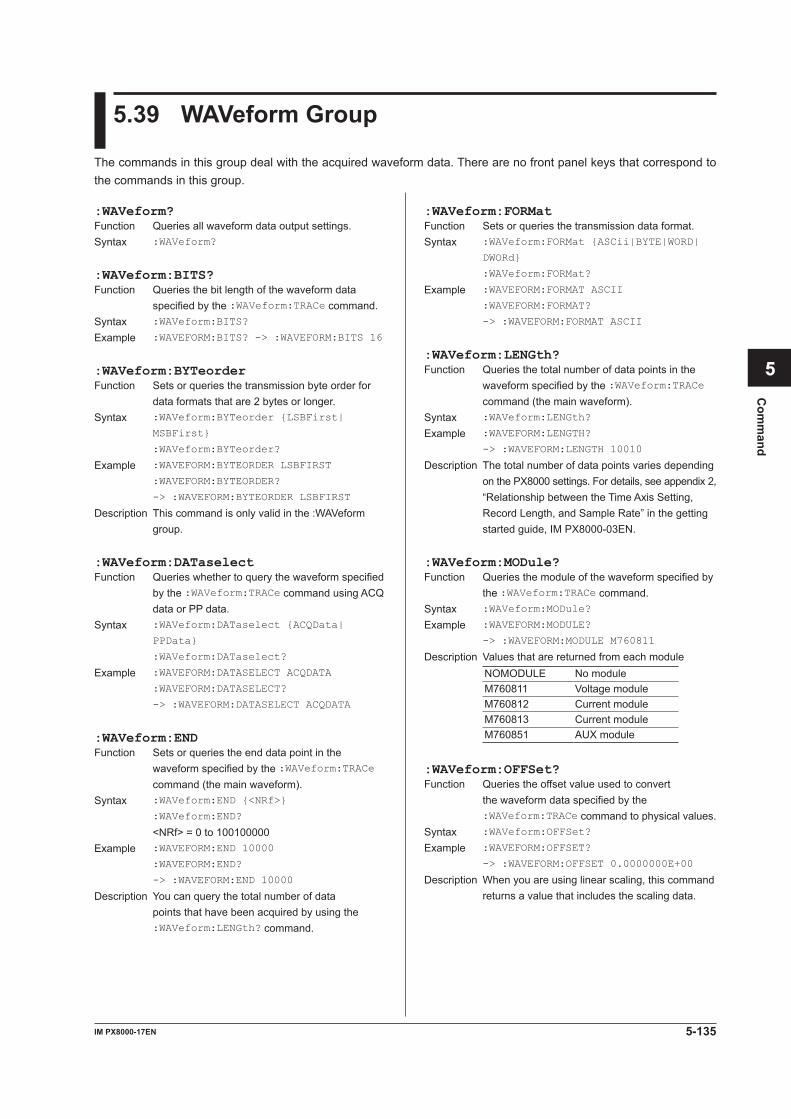
5-135IM PX8000-17EN
Com
mand
1
2
3
4
5
6
App
Index
5.39 WAVeform Group
The commands in this group deal with the acquired waveform data. There are no front panel keys that correspond to the commands in this group.
:WAVeform:FORMatFunction Sets or queries the transmission data format.Syntax :WAVeform:FORMat {ASCii|BYTE|WORD|
DWORd}
:WAVeform:FORMat?
Example :WAVEFORM:FORMAT ASCII
:WAVEFORM:FORMAT?
-> :WAVEFORM:FORMAT ASCII
:WAVeform:LENGth?Function Queries the total number of data points in the
waveform specified by the :WAVeform:TRACe command (the main waveform).
Syntax :WAVeform:LENGth?
Example :WAVEFORM:LENGTH?
-> :WAVEFORM:LENGTH 10010
Description The total number of data points varies depending on the PX8000 settings. For details, see appendix 2, “Relationship between the Time Axis Setting, Record Length, and Sample Rate” in the getting started guide, IM PX8000-03EN.
:WAVeform:MODule?Function Queries the module of the waveform specified by
the :WAVeform:TRACe command.Syntax :WAVeform:MODule?
Example :WAVEFORM:MODULE?
-> :WAVEFORM:MODULE M760811
Description Values that are returned from each moduleNOMODULE No moduleM760811 Voltage moduleM760812 Current moduleM760813 Current moduleM760851 AUX module
:WAVeform:OFFSet?Function Queries the offset value used to convert
the waveform data specified by the :WAVeform:TRACe command to physical values.
Syntax :WAVeform:OFFSet?
Example :WAVEFORM:OFFSET?
-> :WAVEFORM:OFFSET 0.0000000E+00
Description When you are using linear scaling, this command returns a value that includes the scaling data.
:WAVeform?Function Queries all waveform data output settings.Syntax :WAVeform?
:WAVeform:BITS?Function Queries the bit length of the waveform data
specified by the :WAVeform:TRACe command.Syntax :WAVeform:BITS?
Example :WAVEFORM:BITS? -> :WAVEFORM:BITS 16
:WAVeform:BYTeorderFunction Sets or queries the transmission byte order for
data formats that are 2 bytes or longer.Syntax :WAVeform:BYTeorder {LSBFirst|
MSBFirst}
:WAVeform:BYTeorder?
Example :WAVEFORM:BYTEORDER LSBFIRST
:WAVEFORM:BYTEORDER?
-> :WAVEFORM:BYTEORDER LSBFIRST
Description This command is only valid in the :WAVeform group.
:WAVeform:DATaselectFunction Queries whether to query the waveform specified
by the :WAVeform:TRACe command using ACQ data or PP data.
Syntax :WAVeform:DATaselect {ACQData|
PPData}
:WAVeform:DATaselect?
Example :WAVEFORM:DATASELECT ACQDATA
:WAVEFORM:DATASELECT?
-> :WAVEFORM:DATASELECT ACQDATA
:WAVeform:ENDFunction Sets or queries the end data point in the
waveform specified by the :WAVeform:TRACe command (the main waveform).
Syntax :WAVeform:END {<NRf>}
:WAVeform:END?
<NRf> = 0 to 100100000Example :WAVEFORM:END 10000
:WAVEFORM:END?
-> :WAVEFORM:END 10000
Description You can query the total number of data points that have been acquired by using the :WAVeform:LENGth? command.
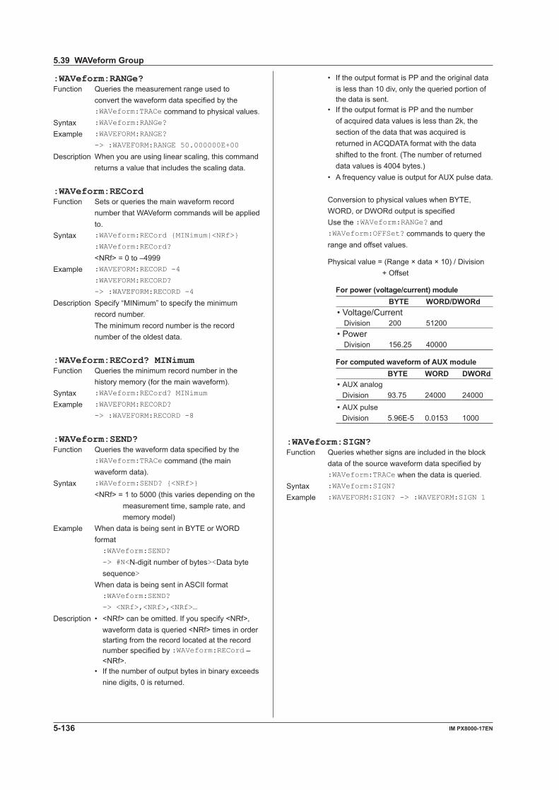
5-136 IM PX8000-17EN
:WAVeform:RANGe?Function Queries the measurement range used to
convert the waveform data specified by the :WAVeform:TRACe command to physical values.
Syntax :WAVeform:RANGe?
Example :WAVEFORM:RANGE?
-> :WAVEFORM:RANGE 50.000000E+00
Description When you are using linear scaling, this command returns a value that includes the scaling data.
:WAVeform:RECordFunction Sets or queries the main waveform record
number that WAVeform commands will be applied to.
Syntax :WAVeform:RECord {MINimum|<NRf>}
:WAVeform:RECord?
<NRf> = 0 to –4999Example :WAVEFORM:RECORD -4
:WAVEFORM:RECORD?
-> :WAVEFORM:RECORD -4
Description Specify “MINimum” to specify the minimum record number.
The minimum record number is the record number of the oldest data.
:WAVeform:RECord? MINimumFunction Queries the minimum record number in the
history memory (for the main waveform).Syntax :WAVeform:RECord? MINimum
Example :WAVEFORM:RECORD?
-> :WAVEFORM:RECORD -8
:WAVeform:SEND?Function Queries the waveform data specified by the
:WAVeform:TRACe command (the main waveform data).
Syntax :WAVeform:SEND? {<NRf>}
<NRf> = 1 to 5000 (this varies depending on the measurement time, sample rate, and memory model)
Example When data is being sent in BYTE or WORD format
:WAVeform:SEND?
-> #N<N-digit number of bytes><Data byte sequence>
When data is being sent in ASCII format :WAVeform:SEND?
-> <NRf>,<NRf>,<NRf>…
Description • <NRf> can be omitted. If you specify <NRf>, waveform data is queried <NRf> times in order starting from the record located at the record number specified by :WAVeform:RECord – <NRf>.
• If the number of output bytes in binary exceeds nine digits, 0 is returned.
• If the output format is PP and the original data is less than 10 div, only the queried portion of the data is sent.
• If the output format is PP and the number of acquired data values is less than 2k, the section of the data that was acquired is returned in ACQDATA format with the data shifted to the front. (The number of returned data values is 4004 bytes.)
• A frequency value is output for AUX pulse data.
Conversion to physical values when BYTE, WORD, or DWORd output is specified
Use the :WAVeform:RANGe? and :WAVeform:OFFSet? commands to query the range and offset values.
Physical value = (Range × data × 10) / Division + Offset
For power (voltage/current) moduleBYTE WORD/DWORd
• Voltage/CurrentDivision 200 51200
• PowerDivision 156.25 40000
For computed waveform of AUX moduleBYTE WORD DWORd
• AUX analogDivision 93.75 24000 24000
• AUX pulseDivision 5.96E-5 0.0153 1000
:WAVeform:SIGN?Function Queries whether signs are included in the block
data of the source waveform data specified by :WAVeform:TRACe when the data is queried.
Syntax :WAVeform:SIGN?
Example :WAVEFORM:SIGN? -> :WAVEFORM:SIGN 1
5.39 WAVeform Group
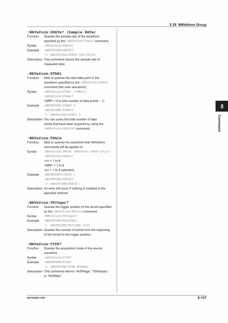
5-137IM PX8000-17EN
Com
mand
1
2
3
4
5
6
App
Index
:WAVeform:SRATe? (Sample RATe)Function Queries the sample rate of the waveform
specified by the :WAVeform:TRACe command.Syntax :WAVeform:SRATe?
Example :WAVEFORM:SRATE?
-> :WAVEFORM:SRATE 500.0E+03
Description This command returns the sample rate of measured data.
:WAVeform:STARtFunction Sets or queries the start data point in the
waveform specified by the :WAVeform:TRACe command (the main waveform).
Syntax :WAVeform:STARt {<NRf>}
:WAVeform:STARt?
<NRf> = 0 to (the number of data points – 1)Example :WAVEFORM:START 0
:WAVEFORM:START?
-> :WAVEFORM:START 0
Description You can query the total number of data points that have been acquired by using the :WAVeform:LENGth? command.
:WAVeform:TRACeFunction Sets or queries the waveform that WAVeform
commands will be applied to.Syntax :WAVeform:TRACe {MATH<x>|<NRf>|P<y>}
:WAVeform:TRACe?
<x> = 1 to 8 <NRf> = 1 to 8 <y> = 1 to 4 (element)Example :WAVEFORM:TRACE 1
:WAVEFORM:TRACE?
-> :WAVEFORM:TRACE 1
Description An error will occur if nothing is installed in the specified channel.
:WAVeform:TRIGger?Function Queries the trigger position of the record specified
by the :WAVeform:RECord command.Syntax :WAVeform:TRIGger?
Example :WAVEFORM:TRIGGER?
-> :WAVEFORM:TRIGGER 5000
Description Queries the number of points from the beginning of the record to the trigger position.
:WAVeform:TYPE?Function Queries the acquisition mode of the source
waveform.Syntax :WAVeform:TYPE?
Example :WAVEFORM:TYPE?
-> :WAVEFORM:TYPE NORMAL
Description This command returns “AVERage,” “ENVelope,” or “NORMal.”
5.39 WAVeform Group
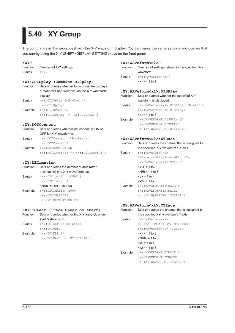
5-138 IM PX8000-17EN
5.40 XY Group
The commands in this group deal with the X-Y waveform display. You can make the same settings and queries that you can by using the X-Y (SHIFT+DISPLAY SETTING) keys on the front panel.
:XY:WAVeform<x1>?Function Queries all settings related to the specified X-Y
waveform.Syntax :XY:WAVeform<x1>?
<x1> = 1 to 8
:XY:WAVeform<x1>:DISPlayFunction Sets or queries whether the specified X-Y
waveform is displayed.Syntax :XY:WAVeform<x1>:DISPlay {<Boolean>}
:XY:WAVeform<x1>:DISPlay?
<x1> = 1 to 8Example :XY:WAVEFORM1:DISPLAY ON
:XY:WAVEFORM1:DISPLAY?
-> :XY:WAVEFORM1:DISPLAY 1
:XY:WAVeform<x1>:XTRaceFunction Sets or queries the channel that is assigned to
the specified X-Y waveform’s X-axis.Syntax :XY:WAVeform<x1>:
XTRace {<NRf>|P<y>|MATH<x2>}
:XY:WAVeform<x1>:XTRace?
<x1> = 1 to 8 <NRf> = 1 to 8 <y> = 1 to 4 <x2> = 1 to 8Example :XY:WAVEFORM1:XTRACE 1
:XY:WAVEFORM1:XTRACE?
-> :XY:WAVEFORM1:XTRACE 1
:XY:WAVeform<x1>:YTRaceFunction Sets or queries the channel that is assigned to
the specified XY- waveform’s Y-axis.Syntax :XY:WAVeform<x1>:
YTRace {<NRf>|P<y>|MATH<x2>}
:XY:WAVeform<x1>:YTRace?
<x1> = 1 to 8 <NRf> = 1 to 8 <y> = 1 to 4 <x2> = 1 to 8Example :XY:WAVEFORM1:YTRACE 2
:XY:WAVEFORM1:YTRACE?
-> :XY:WAVEFORM1:YTRACE 2
:XY?Function Queries all X-Y settings.Syntax :XY?
:XY:CDISplay (Combine DISplay)Function Sets or queries whether to combine the displays
of Window1 and Window2 on the X-Y waveform display.
Syntax :XY:CDISplay {<Boolean>}
:XY:CDISplay?
Example :XY:CDISPLAY ON
:XY:CDISPLAY? -> :XY:CDISPLAY 1
:XY:DOTConnectFunction Sets or queries whether dot connect is ON or
OFF for X-Y waveforms.Syntax :XY:DOTConnect {<Boolean>}
:XY:DOTConnect?
Example :XY:DOTCONNECT ON
:XY:DOTCONNECT? -> :XY:DOTCONNECT 1
:XY:DECimationFunction Sets or queries the number of dots (after
decimation) that X-Y waveforms use.Syntax :XY:DECimation {<NRf>}
:XY:DECimation?
<NRf> = 2000, 100000Example :XY:DECIMATION 2000
:XY:DECIMATION?
-> :XY:DECIMATION 2000
:XY:TCLear (Trace CLear on start)Function Sets or queries whether the X-Y trace-clear-on-
start feature is on.Syntax :XY:TCLear {<Boolean>}
:XY:TCLear?
Example :XY:TCLEAR ON
:XY:TCLEAR? -> :XY:TCLEAR 1
5-139IM PX8000-17EN
Com
mand
1
2
3
4
5
6
App
Index
:XY:WINDow<x>?Function Queries all settings related to the specified X-Y
window.Syntax :XY:WINDow<x>?
<x> = 1, 2
:XY:WINDow<x>:MODEFunction Sets or queries whether the specified X-Y window
is displayed.Syntax :XY:WINDow<x>:MODE {<Boolean>}
:XY:WINDow<x>:MODE?
<x> = 1, 2Example :XY:WINDOW1:MODE ON
:XY:WINDOW1:MODE?
-> :XY:WINDOW1:MODE 1
:XY:WINDow<x>:TRANgeFunction Sets or queries the T-Y waveform range to
display in the XY window.Syntax :XY:WINDow<x>:TRANge {<NRf>,<NRf>}
:XY:WINDow<x>:TRANge?
<NRf> = –5.00 to 5.00 div Resolution: 10/record lengthExample :XY:WINDOW1:TRANGE -5,5
:XY:WINDOW1:TRANGE?
-> :XY:WINDOW1:
TRANGE -5.000000000000,5.000000000000
5.40 XY Group
5-140 IM PX8000-17EN
5.41 ZOOM Group
The commands in this group deal with the zoomed display. You can make the same settings and queries that you can by using the ZOOM key on the front panel.If the selectable range of the time axis is “<NRf> = –5 to 5div,” the selectable range varies depending on settings such as the record length. For details, see “Selectable Range of Cursor Positions” under “Notes about Cursor Measurement” in chapter 15 of IM PX8000-01EN.
:ZOOM:FITMeasureFunction Moves the range on which automated
measurement of waveform parameters is performed to the zoom waveform display frame.
Syntax :ZOOM:FITMeasure {Z1|Z2}
Example :ZOOM:FITMEASURE Z1
:ZOOM:FITMEASURE?
-> :ZOOM:FITMEASURE Z1
:ZOOM:FORMat<x>Function Sets or queries the display format of the specified
zoom waveform.Syntax :ZOOM:FORMat<x> {MAIN|<NRf>}
:ZOOM:FORMat<x>?
<NRf> = 1, 2, 3, 4, 6, 8, 12, 16 <x> = 1, 2 (sets the target zoom box)Example :ZOOM:FORMAT1 1
:ZOOM:FORMAT1? -> :ZOOM:FORMAT1 1
:ZOOM:MAG<x>Function Sets or queries the horizontal magnification of the
specified zoom waveform.Syntax :ZOOM:MAG<x> {<NRf>}
:ZOOM:MAG<x>?
<x> = 1, 2 (sets the target zoom box) <NRf> = 1 to 200000000Example :ZOOM:MAG1 100
:ZOOM:MAG1? -> :ZOOM:MAG1 100.0
Description Use this command when the PX8000 is using an external clock. When the PX8000 is using the internal clock, use the :ZOOM:TDIV<x> command to set the magnification.
The magnification is set as a percentage.
:ZOOM:MAINFunction Sets or queries the proportion of the main
waveform display area that is used when zooming waveforms.
Syntax :ZOOM:MAIN {50|OFF}
:ZOOM:MAIN?
Example :ZOOM:MAIN 50
:ZOOM:MAIN? -> :ZOOM:MAIN 50
:ZOOM?Function Queries all zoom settings.Syntax :ZOOM?
:ZOOM:ASCRoll?Function Queries all auto scroll settings.Syntax :ZOOM:ASCRoll?
:ZOOM:ASCRoll:JUMPFunction Moves the center position of the zoom box to the
left or right edge of the main window.Syntax :ZOOM:ASCRoll:JUMP {LEFT|RIGHt}
Example :ZOOM:ASCROLL:JUMP RIGHT
:ZOOM:ASCRoll:SPEedFunction Sets or queries the auto scroll speed of the zoom
box.Syntax :ZOOM:ASCRoll:SPEed {<NRf>}
:ZOOM:ASCRoll:SPEed?
<NRf> = 1 to 10Example :ZOOM:ASCROLL:SPEED 5
:ZOOM:ASCROLL:SPEED?
-> :ZOOM:ASCROLL:SPEED 5
:ZOOM:ASCRoll:STARtFunction Starts auto scrolling.Syntax :ZOOM:ASCRoll:STARt {LEFT|RIGHt}
Example :ZOOM:ASCROLL:STAR LEFT
:ZOOM:ASCRoll:STOPFunction Stops auto scrolling.Syntax :ZOOM:ASCRoll:STOP
Example :ZOOM:ASCROLL:STOP
:ZOOM:ASCRoll:TARGetFunction Sets or queries the zoom window that will be auto
scrolled.Syntax :ZOOM:ASCRoll:TARGet {Z1|Z2}
:ZOOM:ASCRoll:TARGet?
Example :ZOOM:ASCROLL:TARGET Z1
:ZOOM:ASCROLL:TARGET?
-> :ZOOM:ASCROLL:TARGET Z1
5-141IM PX8000-17EN
Com
mand
1
2
3
4
5
6
App
Index
:ZOOM:MODE<x>Function Sets or queries whether the specified zoom
waveform is displayed.Syntax :ZOOM:MODE<x> {<Boolean>}
:ZOOM:MODE<x>?
Example :ZOOM:MODE1 ON
:ZOOM:MODE1? -> :ZOOM:MODE1 1
:ZOOM:MOVEFunction Moves the zoom box to the start position of the
waveform.Syntax :ZOOM:MOVE {Z1|Z2}
Example :ZOOM:MOVE Z1
:ZOOM:POSition<x>Function Sets or queries the zoom position of the specified
zoom waveform.Syntax :ZOOM:POSition<x> {<NRf>}
:ZOOM:POSition<x>?
<x> = 1, 2 (sets the target zoom box) <NRf> = –5 to 5 divExample :ZOOM:POS1 2
:ZOOM:POS1?
-> :ZOOM:POS1 2.000000000000
:ZOOM:TDIV<x>Function Sets or queries the T/DIV value of the specified
zoom waveform.Syntax :ZOOM:TDIV<x> {<Time>|HOUR1|HOUR2|
HOUR3|HOUR4|HOUR5|HOUR6|HOUR7|HOUR8|
HOUR9|HOUR10|HOUR12|DAY1|DAY2|DAY3}
:ZOOM:TDIV<x>?
<x> = 1, 2 (sets the target zoom box) <Time> = the same as the T/Div settingExample :ZOOM:TDIV1 100us
:ZOOM:TDIV1? -> :ZOOM:TDIV1 100.0E-
06
Description Use this command when the PX8000 is using the internal clock. When the PX8000 is using an external clock, use the :ZOOM:MAG<x> command to set the magnification.
:ZOOM:WLAYout (Window LAYout)Function Sets or queries the window layout that is used
when waveforms are zoomed.Syntax :ZOOM:WLAYout {VERTical|SIDE}
:ZOOM:WLAYout?
Example :ZOOM:WLAY SIDE
:ZOOM:WLAY? -> :ZOOM:WLAY SIDE
:ZOOM:Z2TargetFunction Sets or queries the source window of Z2 when
both Z1 and Z2 are displayed.Syntax :ZOOM:Z2Target {MAIN|Z1}
:ZOOM:Z2Target?
Example :ZOOM:Z2TARGET MAIN
:ZOOM:Z2TARGET?
-> :ZOOM:Z2TARGET MAIN5.41 ZOOM Group
5-142 IM PX8000-17EN
5.42 Common Command Group
The commands in this group are defined in IEEE 488.2-1987 and are independent from the instrument’s individual functions. There are no front panel keys that correspond to the commands in this group.
*ESR?Function Queries and clears the standard event register.Syntax *ESR?
Example *ESR? -> 32
Description • This command returns a sum of the values of each bit in decimal format.
• When an SRQ is sent, you can check what types of events have occurred.
• For example, if a value of 32 is returned, this indicates that the standard event register is set to 00100000. This means that the SRQ occurred due to a command syntax error.
• A query using *ESR? will clear the contents of the standard event register.
• For information about the standard event register, see page 6-3.
*IDN?Function Queries the PX8000 model.Syntax *IDN?
Example *IDN?
-> YOKOGAWA,PX8000,123456789,F1.01
Description This command returns a string in the following format: <Manufacturer>, <Model>, <Serial no.>, <Firmware version>.
*OPCFunction Sets bit 0 (the OPC bit) of the standard event
register to 1 upon the completion of the specified overlap command.
Syntax *OPC
Example *OPC
Description • For details on how to use the *OPC command to synchronize the PX8000, see page 4-8.
• The :COMMunicate:OPSE command is used to specify the overlap command.
• If *OPC is not the last command of the message, its operation is not guaranteed.
*OPC?Function Returns ASCII code 1 when the specified overlap
command is completed.Syntax *OPC?
Example *OPC? -> 1
Description • For details on how to use the *OPC? command to synchronize the PX8000, see page 4-8.
• The :COMMunicate:OPSE command is used to specify the overlap command.
• If *OPC? is not the last command of the message, its operation is not guaranteed.
*CAL?Function Executes calibration and queries the result.Syntax *CAL?
Example *CAL? -> 0
Description This command returns 0 if calibration is completed successfully and 1 otherwise.
*CLSFunction Clears the standard event register, extended
event register, and error queue.Syntax *CLS
Example *CLS
Description • If the *CLS command is located immediately after the program message terminator, the output queue is also cleared.
• For information about each register and queue, see chapter 6.
*ESEFunction Sets or queries the standard event enable
register.Syntax *ESE {<NRf>}
*ESE?
<NRf> = 0 to 255Example *ESE 251
*ESE? -> 251
Description • Specify the value as a sum of the values of each bit in decimal format.
For example, specifying *ESE 251 will cause the standard enable register to be set to 11111011. In this case, bit 2 of the standard event register is disabled. This means that bit 5 (ESB) of the status byte register is not set to 1, even if a query error occurs.
• The default value is *ESE 0 (all bits disabled). • A query using *ESE? will not clear the contents
of the standard event enable register. • For information about the standard event
enable register, see page 6-3.

5-143IM PX8000-17EN
Com
mand
1
2
3
4
5
6
App
Index
*OPT?Function Queries the installed options.Syntax *OPT?
Example *OPT?
-> CH100MPOINTS,PRINTER,IRIG,
HARMONICS,PROBEPOWER
Description This command returns the <size of waveform memory> and whether the <printer>, <IRIG>, <harmonic measurement>, and <probe power supply output> options are installed.
• Size of waveform memory: The total size of waveform data memory.
No options (10 Mpoint): “CH10MPOINTS” /M1 option (50 Mpoints): “CH50MPOINTS” /M2 option (100 Mpoints): “CH100MPOINTS” • Printer: “PRINTER” • IRIG: “IRIG” • Harmonic measurement: “HARMONICS” • Probe power supply output: “PROBEPOWER” • Sensor power supply output /PD: “SENSORPOWER” /PD2: “SENSORPOWER2” An error occurs if there is a query after this
command.
*RSTFunction Initializes settings.Syntax *RST
Example *RST
Description This command also clears the *OPC and *OPC? commands that have been sent.
*SREFunction Sets or queries the service request enable
register value.Syntax *SRE <NRf>
*SRE?
<NRf> = 0 to 255Example *SRE 239
*SRE? -> 175
*STB?Function Queries the status byte register value.Syntax *STB?
Example *STB? -> 4
Description • This command returns a sum of the values of each bit in decimal format.
• Because the register is read without executing serial polling, bit 6 is an MSS bit, not an RQS bit.
For example, if a value of 4 is returned, this indicates that the status byte register is set to 00000100. This means that the error queue is not empty (in other words, an error occurred).
• A query using *STB? will not clear the contents of the status byte register.
• For information about the status byte register, see page 6-2.
*TST?Function Performs a self-test and queries the result. The
self-test consists of tests of each kind of internal memory.
Syntax *TST?
Example *TST? -> 0
Description This command returns 0 if the self-test is successful and 1 otherwise.
*WAIFunction Holds the execution of the subsequent command
until the specified overlap command is completed.Syntax *WAI
Example *WAI
Description • For details on how to use the *WAI command to synchronize the PX8000, see page 4-8.
• The :COMMunicate:OPSE command is used to specify the overlap command.
5.42 Common Command Group
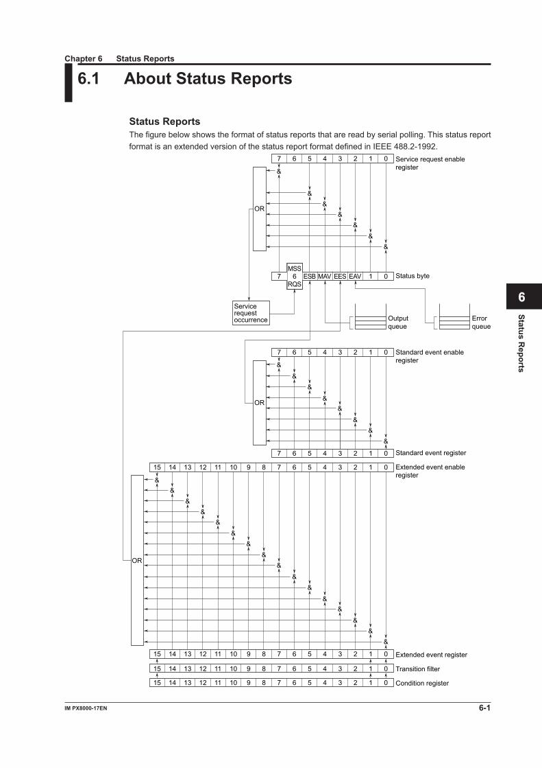
6-1IM PX8000-17EN
Status Reports
1
2
3
4
5
6
App
Index
6.1 About Status Reports
Status ReportsThe figure below shows the format of status reports that are read by serial polling. This status report format is an extended version of the status report format defined in IEEE 488.2-1992.
15 14 13 12 11 10 9 8 7 6 5 4 3 2 1 0
15 14 13 12 11 10 9 8 7 6 5 4 3 2 1 0
15 14 13 12 11 10 9 8 7 6 5 4 3 2 1 0
15 14 13 12 11 10 9 8 7 6 5 4 3 2 1 0
7 6 5 4 3 2 1 0
7 6 5 4 3 2 1 0
OR
OR
7 6 ESB MAV EES EAV 1 0MSS
RQS
7 6 5 4 3 2 1 0
OR
&
&&
&&
&&
&
&
&&
&&
&&
&
&&
&&
&&
&&
&
&&
&&
&&
Condition register
Transition filter
Extended event register
Extended event enable register
Standard event register
Standard event enable register
Status byte
Output queue
Error queue
Service request enable register
Service request occurrence
Chapter 6 Status Reports
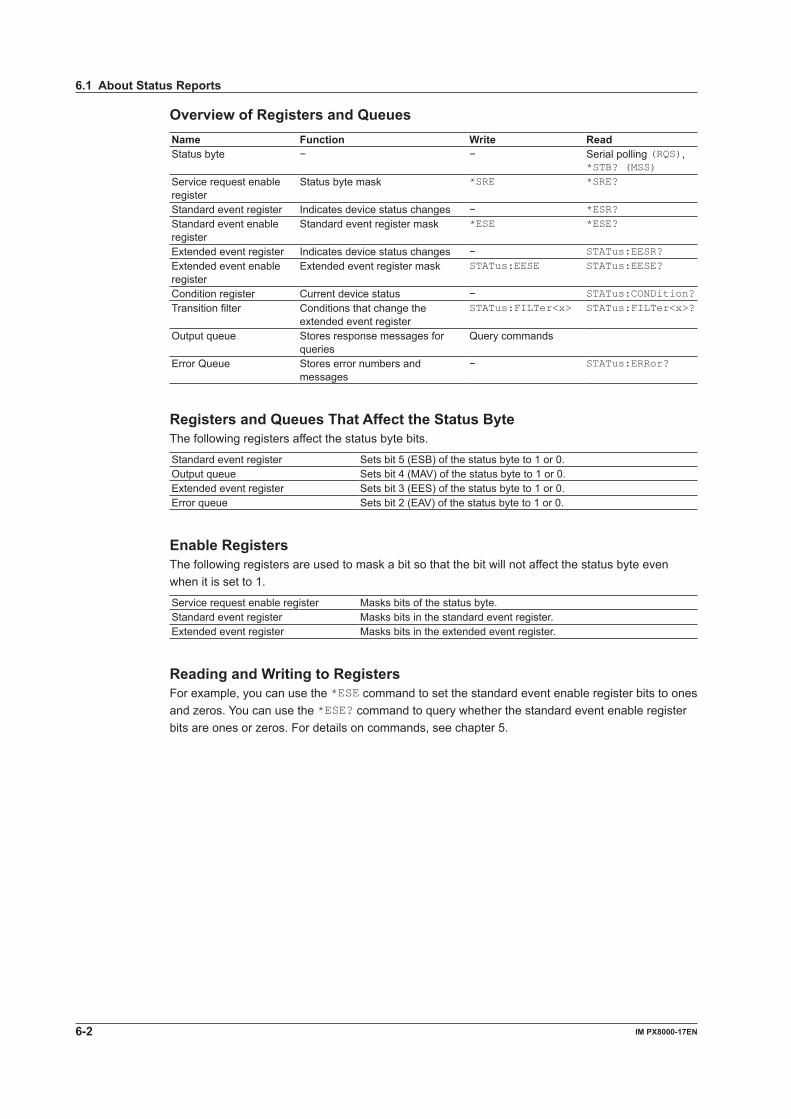
6-2 IM PX8000-17EN
Overview of Registers and QueuesName Function Write ReadStatus byte − − Serial polling (RQS),
*STB? (MSS)Service request enable register
Status byte mask *SRE *SRE?
Standard event register Indicates device status changes − *ESR?Standard event enable register
Standard event register mask *ESE *ESE?
Extended event register Indicates device status changes − STATus:EESR?Extended event enable register
Extended event register mask STATus:EESE STATus:EESE?
Condition register Current device status − STATus:CONDition?Transition filter Conditions that change the
extended event registerSTATus:FILTer<x> STATus:FILTer<x>?
Output queue Stores response messages for queries
Query commands
Error Queue Stores error numbers and messages
− STATus:ERRor?
Registers and Queues That Affect the Status ByteThe following registers affect the status byte bits.
Standard event register Sets bit 5 (ESB) of the status byte to 1 or 0.Output queue Sets bit 4 (MAV) of the status byte to 1 or 0.Extended event register Sets bit 3 (EES) of the status byte to 1 or 0.Error queue Sets bit 2 (EAV) of the status byte to 1 or 0.
Enable RegistersThe following registers are used to mask a bit so that the bit will not affect the status byte even when it is set to 1.
Service request enable register Masks bits of the status byte.Standard event register Masks bits in the standard event register.Extended event register Masks bits in the extended event register.
Reading and Writing to RegistersFor example, you can use the *ESE command to set the standard event enable register bits to ones and zeros. You can use the *ESE? command to query whether the standard event enable register bits are ones or zeros. For details on commands, see chapter 5.
6.1 About Status Reports
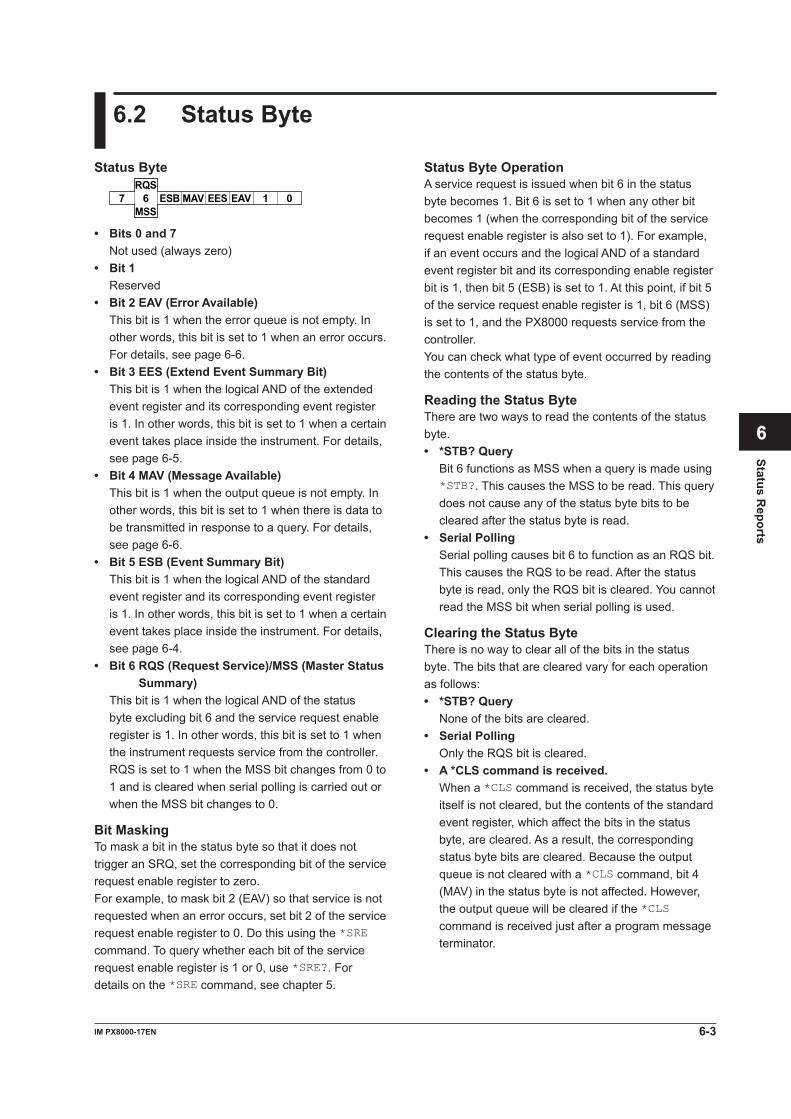
6-3IM PX8000-17EN
Status Reports
1
2
3
4
5
6
App
Index
6.2 Status Byte
Status Byte OperationA service request is issued when bit 6 in the status byte becomes 1. Bit 6 is set to 1 when any other bit becomes 1 (when the corresponding bit of the service request enable register is also set to 1). For example, if an event occurs and the logical AND of a standard event register bit and its corresponding enable register bit is 1, then bit 5 (ESB) is set to 1. At this point, if bit 5 of the service request enable register is 1, bit 6 (MSS) is set to 1, and the PX8000 requests service from the controller.You can check what type of event occurred by reading the contents of the status byte.
Reading the Status ByteThere are two ways to read the contents of the status byte.• *STB? Query Bit 6 functions as MSS when a query is made using
*STB?. This causes the MSS to be read. This query does not cause any of the status byte bits to be cleared after the status byte is read.
• Serial Polling Serial polling causes bit 6 to function as an RQS bit.
This causes the RQS to be read. After the status byte is read, only the RQS bit is cleared. You cannot read the MSS bit when serial polling is used.
Clearing the Status ByteThere is no way to clear all of the bits in the status byte. The bits that are cleared vary for each operation as follows:• *STB? Query None of the bits are cleared.• Serial Polling Only the RQS bit is cleared.• A *CLS command is received. When a *CLS command is received, the status byte
itself is not cleared, but the contents of the standard event register, which affect the bits in the status byte, are cleared. As a result, the corresponding status byte bits are cleared. Because the output queue is not cleared with a *CLS command, bit 4 (MAV) in the status byte is not affected. However, the output queue will be cleared if the *CLS command is received just after a program message terminator.
Status Byte
7 6 ESB MAV EES EAV 1 0RQS
MSS
• Bits 0 and 7Not used (always zero)
• Bit 1Reserved
• Bit 2 EAV (Error Available) This bit is 1 when the error queue is not empty. In
other words, this bit is set to 1 when an error occurs. For details, see page 6-6.
• Bit 3 EES (Extend Event Summary Bit) This bit is 1 when the logical AND of the extended
event register and its corresponding event register is 1. In other words, this bit is set to 1 when a certain event takes place inside the instrument. For details, see page 6-5.
• Bit 4 MAV (Message Available) This bit is 1 when the output queue is not empty. In
other words, this bit is set to 1 when there is data to be transmitted in response to a query. For details, see page 6-6.
• Bit 5 ESB (Event Summary Bit) This bit is 1 when the logical AND of the standard
event register and its corresponding event register is 1. In other words, this bit is set to 1 when a certain event takes place inside the instrument. For details, see page 6-4.
• Bit 6 RQS (Request Service)/MSS (Master Status Summary)
This bit is 1 when the logical AND of the status byte excluding bit 6 and the service request enable register is 1. In other words, this bit is set to 1 when the instrument requests service from the controller.
RQS is set to 1 when the MSS bit changes from 0 to 1 and is cleared when serial polling is carried out or when the MSS bit changes to 0.
Bit MaskingTo mask a bit in the status byte so that it does not trigger an SRQ, set the corresponding bit of the service request enable register to zero.For example, to mask bit 2 (EAV) so that service is not requested when an error occurs, set bit 2 of the service request enable register to 0. Do this using the *SRE command. To query whether each bit of the service request enable register is 1 or 0, use *SRE?. For details on the *SRE command, see chapter 5.
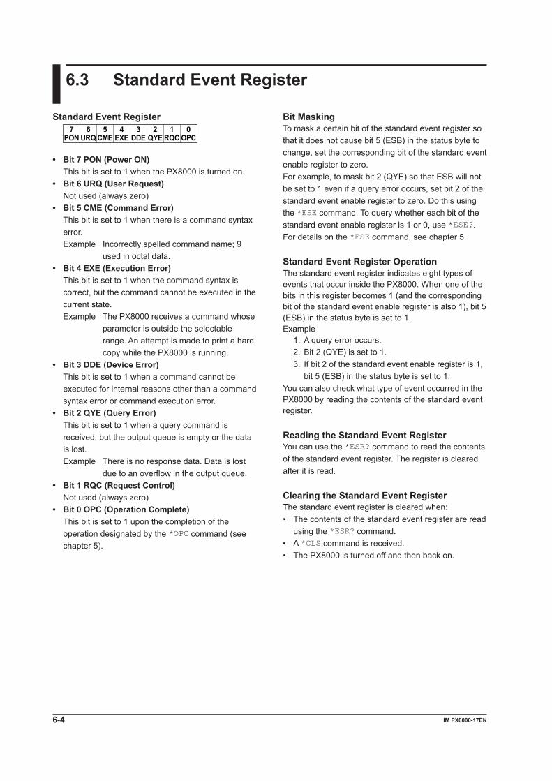
6-4 IM PX8000-17EN
6.3 Standard Event Register
Bit MaskingTo mask a certain bit of the standard event register so that it does not cause bit 5 (ESB) in the status byte to change, set the corresponding bit of the standard event enable register to zero.For example, to mask bit 2 (QYE) so that ESB will not be set to 1 even if a query error occurs, set bit 2 of the standard event enable register to zero. Do this using the *ESE command. To query whether each bit of the standard event enable register is 1 or 0, use *ESE?. For details on the *ESE command, see chapter 5.
Standard Event Register OperationThe standard event register indicates eight types of events that occur inside the PX8000. When one of the bits in this register becomes 1 (and the corresponding bit of the standard event enable register is also 1), bit 5 (ESB) in the status byte is set to 1.Example
1. A query error occurs.2. Bit 2 (QYE) is set to 1.3. If bit 2 of the standard event enable register is 1,
bit 5 (ESB) in the status byte is set to 1.You can also check what type of event occurred in the PX8000 by reading the contents of the standard event register.
Reading the Standard Event RegisterYou can use the *ESR? command to read the contents of the standard event register. The register is cleared after it is read.
Clearing the Standard Event RegisterThe standard event register is cleared when:• The contents of the standard event register are read
using the *ESR? command.• A *CLS command is received.• The PX8000 is turned off and then back on.
Standard Event Register
URQ6
PON7 5 4 3 2 1 0
CME EXE DDE QYE RQC OPC
• Bit 7 PON (Power ON) This bit is set to 1 when the PX8000 is turned on.• Bit 6 URQ (User Request) Not used (always zero)• Bit 5 CME (Command Error) This bit is set to 1 when there is a command syntax
error.Example Incorrectly spelled command name; 9
used in octal data.• Bit 4 EXE (Execution Error) This bit is set to 1 when the command syntax is
correct, but the command cannot be executed in the current state.Example The PX8000 receives a command whose
parameter is outside the selectable range. An attempt is made to print a hard copy while the PX8000 is running.
• Bit 3 DDE (Device Error) This bit is set to 1 when a command cannot be
executed for internal reasons other than a command syntax error or command execution error.
• Bit 2 QYE (Query Error) This bit is set to 1 when a query command is
received, but the output queue is empty or the data is lost.Example There is no response data. Data is lost
due to an overflow in the output queue.• Bit 1 RQC (Request Control) Not used (always zero)• Bit 0 OPC (Operation Complete) This bit is set to 1 upon the completion of the
operation designated by the *OPC command (see chapter 5).
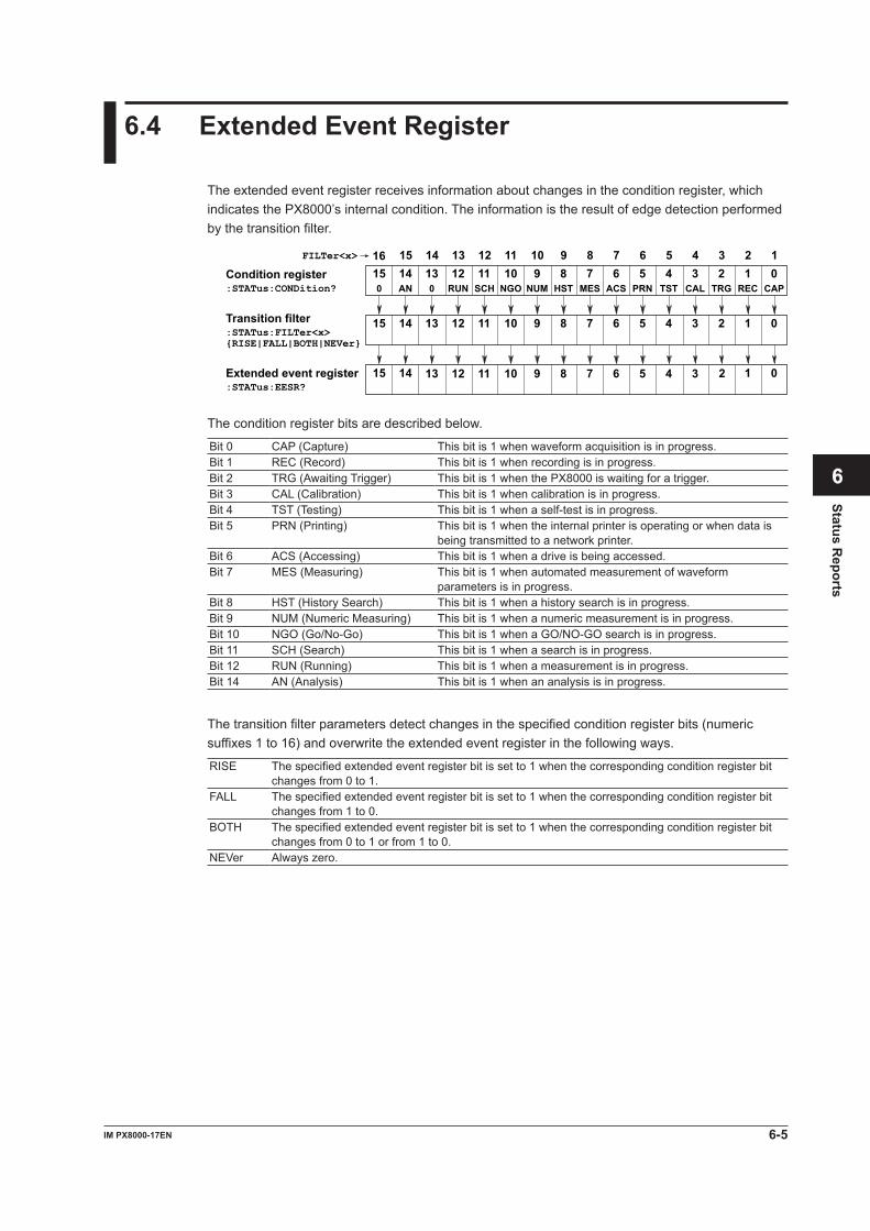
6-5IM PX8000-17EN
Status Reports
1
2
3
4
5
6
App
Index
6.4 Extended Event Register
The extended event register receives information about changes in the condition register, which indicates the PX8000’s internal condition. The information is the result of edge detection performed by the transition filter.
ACS6
HST7 5 4 3 2 1 0
PRN TST CAL TRG REC CAPNGOSCH8
NUM9
MES1011
RUN12
013
AN14
015
67 5 4 3 2 1 089101112131415
01415 167 5 4 38910111213 2
67 5 4 3 2 18910111213141516
:STATus:CONDition?
:STATus:FILTer<x>{RISE|FALL|BOTH|NEVer}
:STATus:EESR?
FILTer<x>
Condition register
Transition filter
Extended event register
The condition register bits are described below.
Bit 0 CAP (Capture) This bit is 1 when waveform acquisition is in progress.Bit 1 REC (Record) This bit is 1 when recording is in progress.Bit 2 TRG (Awaiting Trigger) This bit is 1 when the PX8000 is waiting for a trigger.Bit 3 CAL (Calibration) This bit is 1 when calibration is in progress.Bit 4 TST (Testing) This bit is 1 when a self-test is in progress.Bit 5 PRN (Printing) This bit is 1 when the internal printer is operating or when data is
being transmitted to a network printer.Bit 6 ACS (Accessing) This bit is 1 when a drive is being accessed.Bit 7 MES (Measuring) This bit is 1 when automated measurement of waveform
parameters is in progress.Bit 8 HST (History Search) This bit is 1 when a history search is in progress.Bit 9 NUM (Numeric Measuring) This bit is 1 when a numeric measurement is in progress.Bit 10 NGO (Go/No-Go) This bit is 1 when a GO/NO-GO search is in progress.Bit 11 SCH (Search) This bit is 1 when a search is in progress.Bit 12 RUN (Running) This bit is 1 when a measurement is in progress.Bit 14 AN (Analysis) This bit is 1 when an analysis is in progress.
The transition filter parameters detect changes in the specified condition register bits (numeric suffixes 1 to 16) and overwrite the extended event register in the following ways.
RISE The specified extended event register bit is set to 1 when the corresponding condition register bit changes from 0 to 1.
FALL The specified extended event register bit is set to 1 when the corresponding condition register bit changes from 1 to 0.
BOTH The specified extended event register bit is set to 1 when the corresponding condition register bit changes from 0 to 1 or from 1 to 0.
NEVer Always zero.
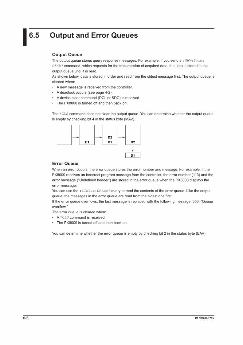
6-6 IM PX8000-17EN
6.5 Output and Error Queues
Output QueueThe output queue stores query response messages. For example, if you send a :WAVeform:SEND? command, which requests for the transmission of acquired data, the data is stored in the output queue until it is read.As shown below, data is stored in order and read from the oldest message first. The output queue is cleared when:• A new message is received from the controller.• A deadlock occurs (see page 4-2).• A device clear command (DCL or SDC) is received.• The PX8000 is turned off and then back on.
The *CLS command does not clear the output queue. You can determine whether the output queue is empty by checking bit 4 in the status byte (MAV).
D1D2D1 D2
D1
Error QueueWhen an error occurs, the error queue stores the error number and message. For example, if the PX8000 receives an incorrect program message from the controller, the error number (113) and the error message (“Undefined header”) are stored in the error queue when the PX8000 displays the error message.You can use the :STATus:ERRor? query to read the contents of the error queue. Like the output queue, the messages in the error queue are read from the oldest one first.If the error queue overflows, the last message is replaced with the following message: 350, “Queue overflow.”The error queue is cleared when:• A *CLS command is received.• The PX8000 is turned off and then back on.
You can determine whether the error queue is empty by checking bit 2 in the status byte (EAV).
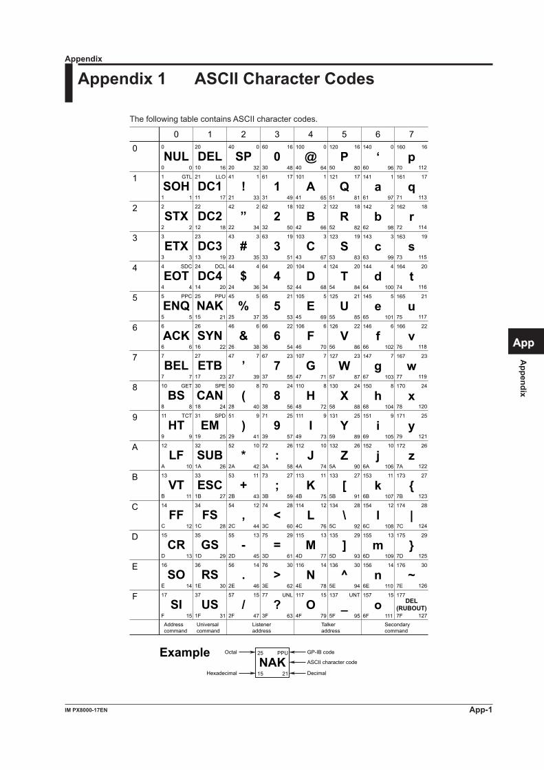
Appendix
App-1IM PX8000-17EN
1
2
3
4
5
6
App
Index
Appendix 1 ASCII Character Codes
The following table contains ASCII character codes.
0
1
2
3
4
5
6
7
10
11
12
13
14
15
16
17
NUL
SOH
STX
ETX
EOT
ENQ
ACK
BEL
BS
HT
LF
VT
FF
CR
SO
SI
20
21
22
23
24
25
26
27
30
31
32
33
34
35
36
37
40
41
42
43
44
45
46
47
50
51
52
53
54
55
56
57
60
61
62
63
64
65
66
67
70
71
72
73
74
75
76
77
100
101
102
103
104
105
106
107
110
111
112
113
114
115
116
117
120
121
122
123
124
125
126
127
130
131
132
133
134
135
136
137
140
141
142
143
144
145
146
147
150
151
152
153
154
155
156
157
160
161
162
163
164
165
166
167
170
171
172
173
174
175
176
177
0
1
2
3
4
5
6
7
8
9
A
B
C
D
E
F
0
1
2
3
4
5
6
7
8
9
A
B
C
D
E
F
10
11
12
13
14
15
16
17
18
19
1A
1B
1C
1D
1E
1F
20
21
22
23
24
25
26
27
28
29
2A
2B
2C
2D
2E
2F
30
31
32
33
34
35
36
37
38
39
3A
3B
3C
3D
3E
3F
40
41
42
43
44
45
46
47
48
49
4A
4B
4C
4D
4E
4F
50
51
52
53
54
55
56
57
58
59
5A
5B
5C
5D
5E
5F
60
61
62
63
64
65
66
67
68
69
6A
6B
6C
6D
6E
6F
70
71
72
73
74
75
76
77
78
79
7A
7B
7C
7D
7E
7F
0
1
2
3
4
5
6
7
8
9
10
11
12
13
14
15
16
17
18
19
20
21
22
23
24
25
26
27
28
29
30
31
32
33
34
35
36
37
38
39
40
41
42
43
44
45
46
47
48
49
50
51
52
53
54
55
56
57
58
59
60
61
62
63
64
65
66
67
68
69
70
71
72
73
74
75
76
77
78
79
80
81
82
83
84
85
86
87
88
89
90
91
92
93
94
95
96
97
98
99
100
101
102
103
104
105
106
107
108
109
110
111
112
113
114
115
116
117
118
119
120
121
122
123
124
125
126
127
GTL
SDC
PPC
GET
TCT
LLO
DCL
PPU
SPE
SPD
0
1
2
3
4
5
6
7
8
9
10
11
12
13
14
15
16
17
18
19
20
21
22
23
24
25
26
27
28
29
30
UNL
DEL
DC1
DC2
DC3
DC4
NAK
SYN
ETB
CAN
EM
SUB
ESC
FS
GS
RS
US
SP
!
”
#
$
%
&
’
(
)
*
+
,
-
.
/
0
1
2
3
4
5
6
7
8
9
:
;
<
=
>
?
@
A
B
C
D
E
F
G
H
I
J
K
L
M
N
O
P
Q
R
S
T
U
V
W
X
Y
Z
[
\
]
^
_
‘
a
b
c
d
e
f
g
h
i
j
k
l
m
n
o
p
q
r
s
t
u
v
w
x
y
z
{
|
}
~
DEL(RUBOUT)
0
1
2
3
4
5
6
7
8
9
10
11
12
13
14
15
16
17
18
19
20
21
22
23
24
25
26
27
28
29
30
UNT
0
1
2
3
4
5
6
7
8
9
10
11
12
13
14
15
16
17
18
19
20
21
22
23
24
25
26
27
28
29
30
Address command
Universal command
Listeneraddress
Talker address
Secondary command
25
15 21
PPU
NAKOctal
Hexadecimal
GP-IB code
Decimal
ASCII character codeExample
0 1 2 3 4 5 6 7
Appendix
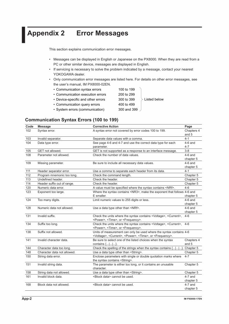
App-2 IM PX8000-17EN
Appendix 2 Error Messages
This section explains communication error messages.
• Messages can be displayed in English or Japanese on the PX8000. When they are read from a PC or other similar device, messages are displayed in English.
• If servicing is necessary to solve the problem indicated by a message, contact your nearest YOKOGAWA dealer.
• Only communication error messages are listed here. For details on other error messages, see the user’s manual, IM PX8000-02EN.
• Communication syntax errors• Communication execution errors• Device-specific and other errors• Communication query errors• System errors (communication)
100 to 199200 to 299300 to 399400 to 499300 and 399
Listed below
Communication Syntax Errors (100 to 199)Code Message Corrective Action Page102 Syntax error. A syntax error not covered by error codes 100 to 199. Chapters 4
and 5103 Invalid separator. Separate data values with a comma. 4-1104 Data type error. See page 4-6 and 4-7 and use the correct data type for each
parameter.4-6 and4-7
105 GET not allowed. GET is not supported as a response to an interface message. 3-8108 Parameter not allowed. Check the number of data values. 4-6 and
chapter 5109 Missing parameter. Be sure to include all necessary data values. 4-6 and
chapter 5111 Header separator error. Use a comma to separate each header from its data. 4-1112 Program mnemonic too long. Check the command length. Chapter 5113 Undefined header. Check the header. Chapter 5114 Header suffix out of range. Check the header. Chapter 5120 Numeric data error. A value must be specified where the syntax contains <NRf>. 4-6123 Exponent too large. Where the syntax contains <NR3>, make the exponent that follows
E smaller.4-6 andchapter 5
124 Too many digits. Limit numeric values to 255 digits or less. 4-6 andchapter 5
128 Numeric data not allowed. Use a data type other than <NRf>. 4-6 andchapter 5
131 Invalid suffix. Check the units where the syntax contains <Voltage>, <Current>, <Power>, <Time>, or <Frequency>.
4-6
134 Suffix too long. Check the units where the syntax contains <Voltage>, <Current>, <Power>, <Time>, or <Frequency>.
4-6
138 Suffix not allowed. Units of measurement can only be used where the syntax contains <Voltage>, <Current>, <Power>, <Time>, or <Frequency>.
4-6
141 Invalid character data. Be sure to select one of the listed choices when the syntax contains {...|...|...}.
Chapters 4and 5
144 Character data too long. Check the spelling of the strings when the syntax contains {...|...|...}. Chapter 5148 Character data not allowed. Use a data type other than <String>. Chapter 5150 String data error. Enclose parameters with single or double quotation marks where
the syntax contains <String>.4-7
151 Invalid string data. The parameter is either too long, or it contains an unusable character.
Chapter 5
158 String data not allowed. Use a data type other than <String>. Chapter 5161 Invalid block data. <Block data> cannot be used. 4-7 and
chapter 5168 Block data not allowed. <Block data> cannot be used. 4-7 and
chapter 5

Appendix
App-3IM PX8000-17EN
1
2
3
4
5
6
App
Index
Code Message Corrective Action Page171 Missing Right Mathematical operations cannot be used. —172 Invalid expression. Mathematical operations cannot be used. Chapter 5178 Expression data not allowed. Mathematical operations cannot be used. Chapter 5181 Invalid outside macro definition. The PX8000 does not support the IEEE 488.2 macro
specifications.—
Communication Execution Errors (200 to 299)Code Message Corrective Action Page221 Setting conflict. Check settings that are related to each other. Chapter 5222 Data out of range. Check the ranges of the settings. Chapter 5223 Too much data. Check data byte lengths. Chapter 5224 Illegal parameter value. Check the ranges of the settings. Chapter 5225 OverFlow. Keep program messages to 1024 bytes or less in length, including
<PMT>.4-2
226 Out Of Memory. Keep program messages to 1024 bytes or less in length, including <PMT>.
4-2
241 Hardware missing. Check that the specified options are all installed. —260 Expression error. Mathematical operations cannot be used. —270 Macro error. The PX8000 does not support the IEEE 488.2 macro
specifications.—
272 Macro execution error. The PX8000 does not support the IEEE 488.2 macro specifications.
—
273 Illegal macro label. The PX8000 does not support the IEEE 488.2 macro specifications.
—
275 Macro definition too long. The PX8000 does not support the IEEE 488.2 macro specifications.
—
276 Macro recursion error. The PX8000 does not support the IEEE 488.2 macro specifications.
—
277 Macro redefinition not allowed. The PX8000 does not support the IEEE 488.2 macro specifications.
—
278 Macro header not found. The PX8000 does not support the IEEE 488.2 macro specifications.
—
Appendix 2 Error Messages
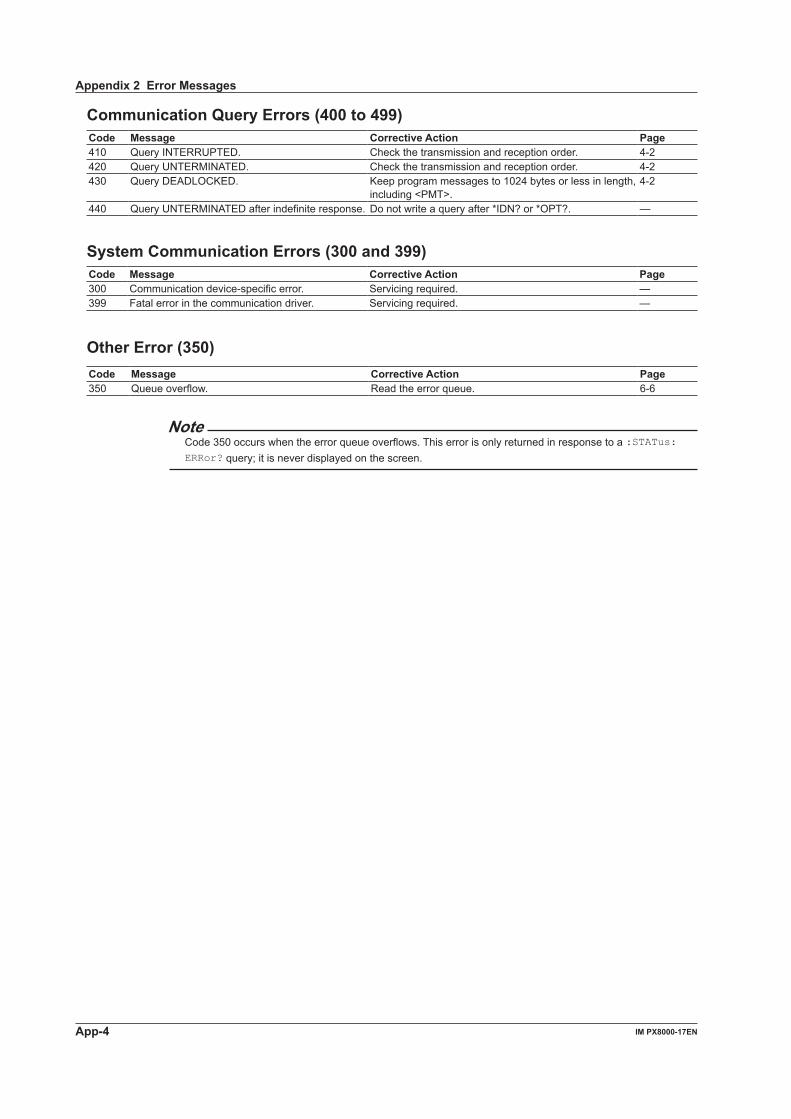
App-4 IM PX8000-17EN
Communication Query Errors (400 to 499)Code Message Corrective Action Page410 Query INTERRUPTED. Check the transmission and reception order. 4-2420 Query UNTERMINATED. Check the transmission and reception order. 4-2430 Query DEADLOCKED. Keep program messages to 1024 bytes or less in length,
including <PMT>.4-2
440 Query UNTERMINATED after indefinite response. Do not write a query after *IDN? or *OPT?. —
System Communication Errors (300 and 399)Code Message Corrective Action Page300 Communication device-specific error. Servicing required. —399 Fatal error in the communication driver. Servicing required. —
Other Error (350)Code Message Corrective Action Page350 Queue overflow. Read the error queue. 6-6
NoteCode 350 occurs when the error queue overflows. This error is only returned in response to a :STATus:ERRor? query; it is never displayed on the screen.
Appendix 2 Error Messages
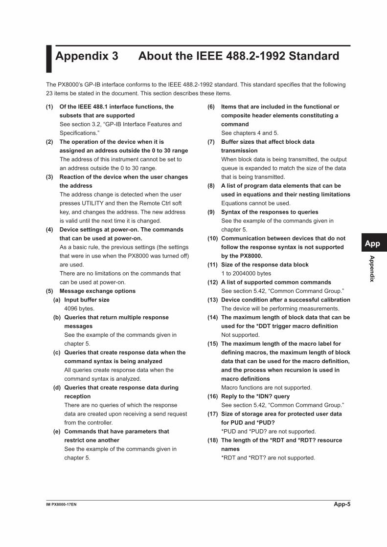
Appendix
App-5IM PX8000-17EN
1
2
3
4
5
6
App
Index
Appendix 3 About the IEEE 488.2-1992 Standard
The PX8000’s GP-IB interface conforms to the IEEE 488.2-1992 standard. This standard specifies that the following 23 items be stated in the document. This section describes these items.
(1) Of the IEEE 488.1 interface functions, the subsets that are supported
See section 3.2, “GP-IB Interface Features and Specifications.”
(2) The operation of the device when it is assigned an address outside the 0 to 30 range
The address of this instrument cannot be set to an address outside the 0 to 30 range.
(3) Reaction of the device when the user changes the address
The address change is detected when the user presses UTILITY and then the Remote Ctrl soft key, and changes the address. The new address is valid until the next time it is changed.
(4) Device settings at power-on. The commands that can be used at power-on.
As a basic rule, the previous settings (the settings that were in use when the PX8000 was turned off) are used.
There are no limitations on the commands that can be used at power-on.
(5) Message exchange options (a) Input buffer size 4096 bytes. (b) Queries that return multiple response
messages See the example of the commands given in
chapter 5. (c) Queries that create response data when the
command syntax is being analyzed All queries create response data when the
command syntax is analyzed. (d) Queries that create response data during
reception There are no queries of which the response
data are created upon receiving a send request from the controller.
(e) Commands that have parameters that restrict one another
See the example of the commands given in chapter 5.
(6) Items that are included in the functional or composite header elements constituting a command
See chapters 4 and 5.(7) Buffer sizes that affect block data
transmission When block data is being transmitted, the output
queue is expanded to match the size of the data that is being transmitted.
(8) A list of program data elements that can be used in equations and their nesting limitations
Equations cannot be used.(9) Syntax of the responses to queries See the example of the commands given in
chapter 5.(10) Communication between devices that do not
follow the response syntax is not supported by the PX8000.
(11) Size of the response data block 1 to 2004000 bytes(12) A list of supported common commands See section 5.42, “Common Command Group.”(13) Device condition after a successful calibration The device will be performing measurements.(14) The maximum length of block data that can be
used for the *DDT trigger macro definition Not supported.(15) The maximum length of the macro label for
defining macros, the maximum length of block data that can be used for the macro definition, and the process when recursion is used in macro definitions
Macro functions are not supported.(16) Reply to the *IDN? query See section 5.42, “Common Command Group.”(17) Size of storage area for protected user data
for PUD and *PUD? *PUD and *PUD? are not supported.(18) The length of the *RDT and *RDT? resource
names *RDT and *RDT? are not supported.
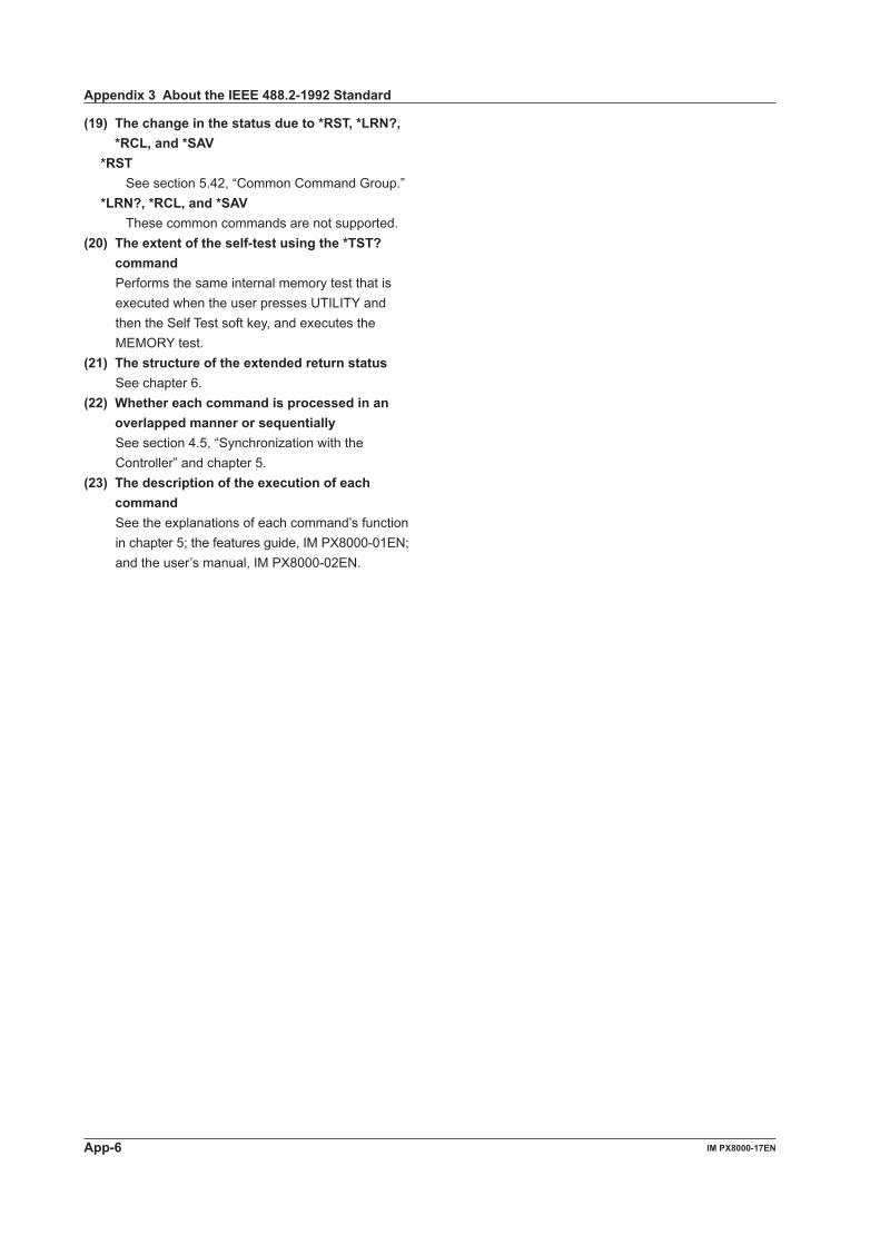
App-6 IM PX8000-17EN
(19) The change in the status due to *RST, *LRN?, *RCL, and *SAV
*RST See section 5.42, “Common Command Group.” *LRN?, *RCL, and *SAV These common commands are not supported.(20) The extent of the self-test using the *TST?
command Performs the same internal memory test that is
executed when the user presses UTILITY and then the Self Test soft key, and executes the MEMORY test.
(21) The structure of the extended return status See chapter 6.(22) Whether each command is processed in an
overlapped manner or sequentially See section 4.5, “Synchronization with the
Controller” and chapter 5.(23) The description of the execution of each
command See the explanations of each command’s function
in chapter 5; the features guide, IM PX8000-01EN; and the user’s manual, IM PX8000-02EN.
Appendix 3 About the IEEE 488.2-1992 Standard
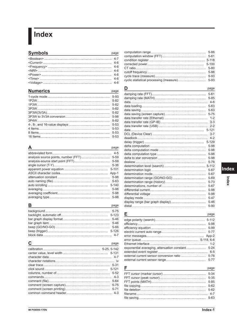
Index-1IM PX8000-17EN
1
2
3
4
5
6
App
Index
Index
Index
Symbols page
<Boolean> ............................................................................ 4-7<Current> ............................................................................. 4-6<Frequency> ........................................................................ 4-6<NRf> ................................................................................... 4-6<Power> ............................................................................... 4-6<Time> ................................................................................. 4-6<Voltage> ............................................................................. 4-6
Numerics page
1-cycle mode ...................................................................... 5-931P2W .................................................................................. 5-821P3W .................................................................................. 5-823P3W .................................................................................. 5-823P3W(3V3A)....................................................................... 5-823P3W to 3V3A conversion .................................................. 5-983P4W .................................................................................. 5-824-, 8-, and 16-value displays .............................................. 5-534 Items ................................................................................ 5-538 Items ................................................................................ 5-5316 Items .............................................................................. 5-53
A page
abbreviated form................................................................... 4-5analysis source points, number (FFT) ................................ 5-59analysis-source start point (FFT) ........................................ 5-59angle cursor (T-Y) ............................................................... 5-36apparent power equation .................................................. 5-101ASCII character codes...................................................... App-1attenuation constant ........................................................... 5-98auto naming (file) ................................................................ 5-63auto scrolling .................................................................... 5-140averaging ............................................................................ 5-98averaging coefficient ........................................................... 5-98averaging type .................................................................... 5-98
B page
background ......................................................................... 5-75backlight, automatic off ..................................................... 5-123bar graph display format ..................................................... 5-46bar graph item .................................................................... 5-46beep (GO/NO-GO) ............................................................. 5-66beep (trigger) .................................................................... 5-126block data ............................................................................. 4-7
C page
calibration ................................................................ 5-25, 5-142center value, level width ................................................... 5-131character data....................................................................... 4-7character notations .................................................................. ivclear trace ........................................................................... 5-31click sound ........................................................................ 5-121columns, number of ............................................................ 5-52commands ............................................................................ 4-3comment (file) ..................................................................... 5-64comment (screen capture).................................................. 5-75comment (screen printing) .................................................. 5-71common command header ................................................... 4-3
computation range .............................................................. 5-86computation window (FFT) ................................................. 5-61condition register ............................................................... 5-118corrected power ................................................................ 5-100CT ratio ............................................................................... 5-80cutoff frequency .................................................................. 5-86cycle trace (measure) ......................................................... 5-93cyclic statistical processing (measure) ............................... 5-93
D page
damping rate (FFT)............................................................. 5-61damping rate (MATH) ......................................................... 5-85data....................................................................................... 4-6data loading ........................................................................ 5-63data saving ......................................................................... 5-63data saving (screen capture) .............................................. 5-75data transfer rate (Ethernet) ................................................. 1-2data transfer rate (GP-IB) ..................................................... 3-3data transfer rate (USB) ....................................................... 2-2date................................................................................... 5-121DCL (Device Clear) .............................................................. 3-7deadlock ............................................................................... 4-2delay (trigger) ................................................................... 5-129delta computation ............................................................... 5-98delta computation mode ..................................................... 5-98delta computation type ....................................................... 5-98delta to star conversion ...................................................... 5-98deskew ............................................................................... 5-78determination level (search) .............................................. 5-112determination logic ............................................................. 5-67determination mode ............................................................ 5-67determination range (GO/NO-GO) ..................................... 5-69determination range (history).............................................. 5-73determinations, number of .................................................. 5-67differential current ............................................................... 5-98differential voltage .............................................................. 5-98display mode ...................................................................... 5-47display range (bar graph display) ....................................... 5-46distal ................................................................................... 5-90
E page
edge polarity (search) ........................................................ 5-112efficiency ............................................................................. 5-98efficiency equation .............................................................. 5-99electric current auto range .................................................. 5-77error messages................................................................. App-2error queue ................................................................ 5-118, 6-6Ethernet interface ................................................................. 1-2exponential averaging, attenuation constant ...................... 5-24extended event register ........................................................ 6-5external current sensor conversion ratio ............................ 5-78external current sensor range............................................. 5-77
F page
FFT cursor (marker cursor) ................................................ 5-34FFT cursor (peak cursor) .................................................... 5-35FFT points (MATH) ............................................................. 5-85file copying.......................................................................... 5-62file deletion ......................................................................... 5-62filename ................................................................................ 4-7file saving............................................................................ 5-63
Index-2 IM PX8000-17EN
Indexfilter band ............................................................................ 5-85filter (MATH) ....................................................................... 5-85filter type ............................................................................. 5-86font size ............................................................................ 5-124format (system) ................................................................. 5-124format (waveform) ............................................................ 5-135format (zoom) ................................................................... 5-140frequency filter .................................................................... 5-79front panel............................................................... 1-1, 2-1, 3-1function options .................................................................. 5-57
G page
GP-IB board.......................................................................... 3-4GP-IB interface ..................................................................... 3-2groups................................................................................... 4-3GTL (Go To Local) ................................................................ 3-7
H page
hold-off time ...................................................................... 5-130horizontal cursor (T-Y) ........................................................ 5-38horizontal cursor (X-Y)........................................................ 5-42horizontal magnification (zoom)........................................ 5-140
I page
IFC (Interface Clear) ............................................................. 3-7independent power measurement element configuration... 5-80Initialization ......................................................................... 5-76input coupling ..................................................................... 5-26instant start (on start).......................................................... 5-83intensity .............................................................................. 5-47IRIG format ....................................................................... 5-122IRIG modulation................................................................ 5-122
K page
key lock............................................................................. 5-122
L page
LCD brightness ................................................................. 5-123level range ........................................................................ 5-132linear scaling....................................................................... 5-27line filter .............................................................................. 5-79LLO (Local Lockout) ............................................................. 3-7local lockout ........................................................................ 5-32logic condition (history) ....................................................... 5-74logic (history) ...................................................................... 5-73
M page
manual trigger..................................................................... 5-97marker cursor (T-Y) ............................................................ 5-39marker cursor (X-Y) ............................................................ 5-43maximum analyzed harmonic order ................................... 5-70medium, free space ............................................................ 5-62menu language ................................................................. 5-123mesial ................................................................................. 5-90message language ........................................................... 5-123messages ............................................................................. 4-1minimum analyzed harmonic order .................................... 5-70motor mode ........................................................................ 5-95motor output ....................................................................... 5-95motor output computation, scaling factor............................ 5-95moving average count ........................................................ 5-98
N page
no-go count......................................................................... 5-67NULL feature .................................................................... 5-102numeric data ..................................................................... 5-103
all items display ............................................................ 5-47display format ............................................................... 5-51display item (4-, 8-, and 16-value displays) .................. 5-54display item (custom display) ....................................... 5-50display item (matrix display) ......................................... 5-53display item (single harmonics and dual harmonics lists) ......
5-52format .............................................................. 5-103, 5-107output item ................................................................. 5-106
O page
offset B ............................................................................... 5-27offset voltage ...................................................................... 5-28output queue......................................................................... 6-6overlap commands ............................................................... 4-8
P page
P1:X, P2:X .......................................................................... 5-28P1:Y, P2:Y .......................................................................... 5-28Pc ..................................................................................... 5-100peak over-range ................................................................. 5-80phase difference display format ........................................ 5-101phase shift (external clock) ................................................. 5-85phase shift (internal clock) .................................................. 5-87PLL source ......................................................................... 5-70Pm ...................................................................................... 5-95power coefficient ................................................................. 5-80probe .................................................................................. 5-29program message................................................................. 4-1proximal .............................................................................. 5-90pulse reference level .......................................................... 5-29pulse/rotate ......................................................................... 5-24
Q page
query..................................................................................... 4-1
R page
record length....................................................................... 5-24reference condition (history) ............................................... 5-72reference condition (parameter) ......................................... 5-68reference condition (waveform zone) ................................. 5-69register.................................................................................. 4-7remote and local modes, switching ........................ 1-2, 2-2, 3-3remote or local .................................................................... 5-32remote terminal................................................................. 5-124REN (Remote Enable) .......................................................... 3-7response ............................................................................... 4-5response message ............................................................... 4-1responses without headers................................................... 4-5rotating speed ..................................................................... 5-95
S page
sample rate ....................................................................... 5-125save file name .................................................................... 5-65scaling ................................................................................ 5-80scaling coefficient A ............................................................ 5-27scaling (MATH) ................................................................... 5-86screen, base color .............................................................. 5-46screen capture printing (GO/NO-GO) ................................. 5-66screen capture printing (trigger) ....................................... 5-126
Index-3IM PX8000-17EN
1
2
3
4
5
6
App
Index
Index
Indexscreen capture saving (GO/NO-GO) .................................. 5-66screen capture saving (trigger) ......................................... 5-126SDC (Selected Device Clear) ............................................... 3-7search end position ........................................................... 5-112search (history) ................................................................... 5-72search start position .......................................................... 5-113self-test ............................................................................. 5-143side panel ............................................................... 1-1, 2-1, 3-1single-phase, three-wire ..................................................... 5-82single-phase, two-wire ........................................................ 5-82single start ......................................................................... 5-116snapshot ............................................................................ 5-115SNTP ................................................................................ 5-121SPD (Serial Poll Disable)...................................................... 3-7speed .................................................................................. 5-95SPE (Serial Poll Enable)....................................................... 3-7standard event register ......................................................... 6-4star to delta conversion ...................................................... 5-98START/STOP key ............................................................. 5-123status byte ............................................................................ 6-3status reports ........................................................................ 6-1string data ............................................................................. 4-7synchronization source ....................................................... 5-81
T page
TCP/IP .................................................................................. 1-5T/DIV ................................................................................ 5-141T/DIV (time base) ............................................................. 5-125THD .................................................................................... 5-70three-phase, four-wire ........................................................ 5-82three-phase, three-wire ...................................................... 5-82three-voltage, three-current measurement method ............ 5-82threshold level (MATH) ....................................................... 5-84time ................................................................................... 5-121time base ............................................................................ 5-24time base (TIME/DIV) ....................................................... 5-125timeout (cursor) .................................................................. 5-42timeout (GO/NO-GO) .......................................................... 5-69timeout (measure) .............................................................. 5-94timeout (single start) .......................................................... 5-116timeout value ........................................................................ 1-3time search, time of ........................................................... 5-113time synchronization ......................................................... 5-124time window ........................................................................ 5-85TMCTL ...................................................................................... iitorque ................................................................................. 5-96total harmonic distortion ..................................................... 5-70trace-clear-on-start ........................................................... 5-138transition filter ....................................................................... 6-5trigger
A->B(n) ....................................................................... 5-126A Delay B ................................................................... 5-128AND ............................................................................ 5-128B Between .................................................................. 5-128B<Time ....................................................................... 5-128B>Time ....................................................................... 5-128B TimeOut .................................................................. 5-129EdgeOnA .................................................................... 5-129enhanced ................................................................... 5-131simple ......................................................................... 5-131T1<T<T2 .................................................................... 5-133time ............................................................................ 5-132T<T1,T2<T ................................................................. 5-133T<Time ....................................................................... 5-133T>Time ....................................................................... 5-132wave window .............................................................. 5-132
trigger date (history) ........................................................... 5-72
trigger position .................................................................. 5-130trigger time (history)............................................................ 5-73
U page
unit (linear scaling) ............................................................. 5-28unit (MATH) ........................................................................ 5-87upper-level query .................................................................. 4-4USB cable............................................................................. 2-3USB hub ............................................................................... 2-3USB interface ....................................................................... 2-2USB keyboard .................................................................. 5-124user-defined function .......................................................... 5-99user-defined function, equation .......................................... 5-99user-defined function, name ............................................... 5-99
V page
vector display format .......................................................... 5-54vertical cursor (T-Y) ............................................................ 5-40vertical cursor (X-Y) ............................................................ 5-45vertical position ................................................................... 5-29vertical scale ....................................................................... 5-30vertical scale, center value ................................................. 5-61vertical scale sensitivity (FFT) ............................................ 5-61vertical zoom ...................................................................... 5-30voltage auto range .............................................................. 5-81voltage range ...................................................................... 5-82voltage range (AUX) ........................................................... 5-29VT ratio ............................................................................... 5-80
W page
waveform acquisition .......................................................... 5-24waveform acquisitions, number of ...................................... 5-24waveform interpolation ....................................................... 5-56waveform label (frequency) ................................................ 5-26waveform label (MATH) ...................................................... 5-86waveform saving (GO/NO-GO) .......................................... 5-67Window1 and Window2, combined display (X-Y) ............. 5-138window layout (zoom) ....................................................... 5-141wiring system ...................................................................... 5-82
Z page
zoom position ................................................................... 5-141