PWTB 420-49-5 Industrial Water Treatment Procedures
153
PUBLIC WORKS TECHNICAL BULLETIN 420-49-05 2 FEBRUARY 1998 INDUSTRIAL WATER TREATMENT PROCEDURES
Transcript of PWTB 420-49-5 Industrial Water Treatment Procedures
PUBLIC WORKS TECHNICAL BULLETIN 420-49-052 FEBRUARY 1998
INDUSTRIAL WATER TREATMENT PROCEDURES
DEPARTMENT OF THE ARMYU.S. Army Center for Public Works
7701 Telegraph RoadAlexandria, VA 22315-3862
Public Works Technical Bulletin 2 February 1998No. 420-49-05
FACILITIES ENGINEERINGUtilities
INDUSTRIAL WATER TREATMENT PROCEDURES
1. Purpose. This Public Works Technical Bulletin (PWTB) transmits the Industrial WaterTreatment Procedures handbook. The procedures provide information on the application,selection, procurement and implementation of water treatment procedures and chemicals requiredto properly operate boiler and cooling systems and maintain the waterside surfaces. Theprocedures improve maintenance, efficiency, reliability, treatment, system life and safety of boilerand cooling systems. The boiler and cooling systems include steam boilers, hot water boilers,chilled water systems, cooling towers and other industrial systems.
2. Applicability. This PWTB applies to all U.S. Army Public Works activities responsible foroperating and maintaining boiler, cooling tower and HVAC systems.
3. References.
a. Army Regulation 420-49, Facilities Engineering, Utility Services, April 1997.
b. TM 5-650, Central Boiler Plants, October 1989.
c. TM 5-642, Operation and Maintenance Small Heating Systems, August 1990.
d. TM 5-671, Preventive Maintenance for Refrigeration, Air Conditioning, MechanicalVentilation, and Evaporative Cooling, August 1958.
4. Discussion.
a. Many installations across the country are facing problems in industrial water systems(i.e., boiler and cooling systems). One of the most common problems is difficulty in preventingthe formation of scale or the occurrence of corrosion in heating and cooling systems. As a resultof these problems, system life, reliability, efficiency and safety are reduced. Many of these
PWTB No. 420-49-05 2 February 1998
2
problems are preventable through proper boiler/cooling water chemistry maintenance andtreatment.
b. Army policy requires generic chemicals for the treatment of central boiler plant systemwater. TM 5-650 provides basic guidance on the application of chemicals to steam and hot waterboiler water. This PWTB amplifies the correct chemical treatment of boilers and adds requiredchemical treatment for cooling towers and chilled water systems. It also provides procedures forthe economical, safe and efficient control of heating and cooling systems while setting specificstandards for water treatment.
c. This PWTB provides one consolidated guide for chemical treatment of all HVACsystems.
5. Point of contact. Questions and/or comments regarding this subject, which cannot be resolvedat the installation level, should be directed to:
U.S. Army Center for Public WorksNelson Labbé ATTN: CECPW-ES7701 Telegraph RoadAlexandria, VA 22315-3862Telephone: (703) 806-5202, DSN: 656-5202FAX: (703) 806-5216e-mail: [email protected]
FOR THE DIRECTOR:
EVANGELOS P. STOYAS, P.E.Acting Director of Engineering

Public Works Technical Bulletins are published by the U.S. Army Center for Public Works,Alexandria, VA. They are intended to provide information on specific topics in areas of FacilitiesEngineering and Public Works. They are not intended to establish new DA policy.

PWTB 420-49-52 February 1998
This publication may be reproduced.

INDUSTRIAL WATER TREATMENT PROCEDURES
2 FEBRUARY 1998
i
Approved for public release
INDUSTRIAL WATER TREATMENT PROCEDURESHANDBOOK
Paragraph Page
CHAPTER 1. INTRODUCTION TO INDUSTRIAL WATER TREATMENTSection I. Industrial Water Treatment Policy
Industrial Water Defined . . . . . . . . . . . . . . . . . . . . . . . . . . . . . . . . . . . . . . 1-1 1-1Problems Encountered in Industrial Water Systems . . . . . . . . . . . . . . . . . . . 1-2 1-1Objective of Industrial Water Treatment . . . . . . . . . . . . . . . . . . . . . . . . . . . 1-3 1-1Responsibility for Treatment . . . . . . . . . . . . . . . . . . . . . . . . . . . . . . . . . . . 1-4 1-2Unauthorized Treatment . . . . . . . . . . . . . . . . . . . . . . . . . . . . . . . . . . . . . . . 1-5 1-2Protecting Health . . . . . . . . . . . . . . . . . . . . . . . . . . . . . . . . . . . . . . . . . . . . 1-6 1-2Record Keeping Requirements . . . . . . . . . . . . . . . . . . . . . . . . . . . . . . . . . . 1-7 1-3Support Available . . . . . . . . . . . . . . . . . . . . . . . . . . . . . . . . . . . . . . . . . . . 1-8 1-4
Section II. Safety and First AidSafety Considerations . . . . . . . . . . . . . . . . . . . . . . . . . . . . . . . . . . . . . . . . . 1-9 1-4First Aid Information . . . . . . . . . . . . . . . . . . . . . . . . . . . . . . . . . . . . . . . . 1-10 1-5
Section III. Disposal of Industrial Water WastesDisposal Procedures . . . . . . . . . . . . . . . . . . . . . . . . . . . . . . . . . . . . . . . . . 1-11 1-5Regulations That May Apply . . . . . . . . . . . . . . . . . . . . . . . . . . . . . . . . . . 1-12 1-6
CHAPTER 2. MAKEUP WATERSection I. General Information
Industrial Water . . . . . . . . . . . . . . . . . . . . . . . . . . . . . . . . . . . . . . . . . . . . . 2-1 2-1Sources of Makeup Water . . . . . . . . . . . . . . . . . . . . . . . . . . . . . . . . . . . . . 2-2 2-1Source Selection Factors to Consider . . . . . . . . . . . . . . . . . . . . . . . . . . . . . 2-3 2-1Reasons and Criteria for Treating Makeup Water . . . . . . . . . . . . . . . . . . . . 2-4 2-1
Section II. Methods of TreatmentGeneral Discussion . . . . . . . . . . . . . . . . . . . . . . . . . . . . . . . . . . . . . . . . . . 2-5 2-2Aeration . . . . . . . . . . . . . . . . . . . . . . . . . . . . . . . . . . . . . . . . . . . . . . . . . . . 2-6 2-2Filtration . . . . . . . . . . . . . . . . . . . . . . . . . . . . . . . . . . . . . . . . . . . . . . . . . . 2-7 2-6Lime-Soda Softening . . . . . . . . . . . . . . . . . . . . . . . . . . . . . . . . . . . . . . . . . 2-8 2-6Ion Exchange Processes-General . . . . . . . . . . . . . . . . . . . . . . . . . . . . . . . . 2-9 2-6Sodium Ion Exchange . . . . . . . . . . . . . . . . . . . . . . . . . . . . . . . . . . . . . . . . 2-10 2-7Hydrogen Ion Exchange . . . . . . . . . . . . . . . . . . . . . . . . . . . . . . . . . . . . . . 2-11 2-10Anion Exchange . . . . . . . . . . . . . . . . . . . . . . . . . . . . . . . . . . . . . . . . . . . . 2-12 2-11Dealkalization . . . . . . . . . . . . . . . . . . . . . . . . . . . . . . . . . . . . . . . . . . . . . 2-13 2-11
ii
Paragraph Page
Decarbonation . . . . . . . . . . . . . . . . . . . . . . . . . . . . . . . . . . . . . . . . 2-14 2-13Evaporation . . . . . . . . . . . . . . . . . . . . . . . . . . . . . . . . . . . . . . . . . . 2-15 2-13Reverse Osmosis . . . . . . . . . . . . . . . . . . . . . . . . . . . . . . . . . . . . . . 2-16 2-13Ultrafiltration . . . . . . . . . . . . . . . . . . . . . . . . . . . . . . . . . . . . . . . . . 2-17 2-18Electrodialysis . . . . . . . . . . . . . . . . . . . . . . . . . . . . . . . . . . . . . . . . 2-18 2-18
CHAPTER 3. STEAM BOILER SYSTEMSSection I. General Information
Boiler System Defined . . . . . . . . . . . . . . . . . . . . . . . . . . . . . . . . . . . 3-1 3-1Components of a Steam Boiler . . . . . . . . . . . . . . . . . . . . . . . . . . . . . 3-2 3-1Total Dissolved Solids (TDS) and Alkalinity . . . . . . . . . . . . . . . . . . 3-3 3-2Boiler Blowdown Calculations . . . . . . . . . . . . . . . . . . . . . . . . . . . . . 3-4 3-4Determining Feedwater Requirements . . . . . . . . . . . . . . . . . . . . . . . 3-5 3-6Determining Makeup Requirements . . . . . . . . . . . . . . . . . . . . . . . . . 3-6 3-7Determining Chemical Treatment Required . . . . . . . . . . . . . . . . . . . 3-7 3-8
Section II. Boiler Water Treatment and ControlDeposit Formation . . . . . . . . . . . . . . . . . . . . . . . . . . . . . . . . . . . . . . 3-8 3-9Problems Caused by Scaling . . . . . . . . . . . . . . . . . . . . . . . . . . . . . . . 3-9 3-10Common Scales Found in Boilers . . . . . . . . . . . . . . . . . . . . . . . . . . 3-10 3-10Internal Treatment of Boiler Water . . . . . . . . . . . . . . . . . . . . . . . . 3-11 3-10Water Carryover in Steam . . . . . . . . . . . . . . . . . . . . . . . . . . . . . . . 3-12 3-11Removal of Oxygen From Feedwater . . . . . . . . . . . . . . . . . . . . . . . 3-13 3-13Condensate Corrosion and Control . . . . . . . . . . . . . . . . . . . . . . . . 3-14 3-15
Section III. Putting It All TogetherGeneral Information . . . . . . . . . . . . . . . . . . . . . . . . . . . . . . . . . . . . 3-15 3-18Determining Blowdown Required . . . . . . . . . . . . . . . . . . . . . . . . . 3-16 3-18Determining Phosphate Required to Replace Blowdown Loss . . . . 3-17 3-20Determining Phosphate Required for Hardness Reaction . . . . . . . . 3-18 3-21Determining Sodium Hydroxide (Caustic Soda) Required . . . . . . . 3-19 3-23Determining Synthetic Polymer Dosage . . . . . . . . . . . . . . . . . . . . . 3-20 3-23Determining Sulfite Dosage . . . . . . . . . . . . . . . . . . . . . . . . . . . . . . 3-21 3-23Determining Amine Dosage . . . . . . . . . . . . . . . . . . . . . . . . . . . . . . 3-22 3-24Summary of Required Calculations . . . . . . . . . . . . . . . . . . . . . . . . . 3-23 3-24
Section IV. Boiler Layup RequirementsGeneral Information . . . . . . . . . . . . . . . . . . . . . . . . . . . . . . . . . . . . 3-24 3-25Dry Layup . . . . . . . . . . . . . . . . . . . . . . . . . . . . . . . . . . . . . . . . . . . 3-25 3-25Wet Layup . . . . . . . . . . . . . . . . . . . . . . . . . . . . . . . . . . . . . . . . . . . 3-26 3-26
CHAPTER 4. COOLING TOWERSSection I. General Information
Open Recirculating Systems Defined . . . . . . . . . . . . . . . . . . . . . . . . 4-1 4-1Fundamental Parts of a Cooling Tower . . . . . . . . . . . . . . . . . . . . . . 4-2 4-1Objective of Cooling Water Treatment . . . . . . . . . . . . . . . . . . . . . . . 4-3 4-2
Section II. Cooling Tower Operating Calculations
iii
Paragraph Page
Principles of Cooling Tower Operations . . . . . . . . . . . . . . . . . . . . . . 4-4 4-2Relationship Between Evaporation, Blowdown, and Makeup . . . . . . 4-5 4-4Cycles of Concentration . . . . . . . . . . . . . . . . . . . . . . . . . . . . . . . . . . 4-6 4-4Relationship Between Blowdown, Evaporation, and Cycles of Concentration . . . . . . . . . . . . . . . . . . . . . . . . . . . . . . . . . . . . . . 4-7 4-6
Section III. Deposit Formation and ControlTypes of Deposits . . . . . . . . . . . . . . . . . . . . . . . . . . . . . . . . . . . . . . 4-8 4-6Causes of Scale . . . . . . . . . . . . . . . . . . . . . . . . . . . . . . . . . . . . . . . . 4-9 4-6Determining Scaling Limits . . . . . . . . . . . . . . . . . . . . . . . . . . . . . . 4-10 4-8Use of Scaling Indices . . . . . . . . . . . . . . . . . . . . . . . . . . . . . . . . . . 4-11 4-9Scale Control . . . . . . . . . . . . . . . . . . . . . . . . . . . . . . . . . . . . . . . . . 4-12 4-10Causes of Fouling . . . . . . . . . . . . . . . . . . . . . . . . . . . . . . . . . . . . . 4-13 4-11Fouling Control . . . . . . . . . . . . . . . . . . . . . . . . . . . . . . . . . . . . . . . 4-14 4-11
Section IV. Microbiological Deposits and ControlGeneral Information . . . . . . . . . . . . . . . . . . . . . . . . . . . . . . . . . . . . 4-15 4-11Microbiological Control . . . . . . . . . . . . . . . . . . . . . . . . . . . . . . . . . 4-16 4-12Legionnaires’ Disease . . . . . . . . . . . . . . . . . . . . . . . . . . . . . . . . . . 4-17 4-13
Section V. Corrosion in Cooling SystemsDefinition of Corrosion . . . . . . . . . . . . . . . . . . . . . . . . . . . . . . . . . 4-18 4-13Corrosion Rates . . . . . . . . . . . . . . . . . . . . . . . . . . . . . . . . . . . . . . . 4-19 4-15Methods of Corrosion Control . . . . . . . . . . . . . . . . . . . . . . . . . . . . 4-20 4-15
Section VI. Putting It All TogetherGeneral Information . . . . . . . . . . . . . . . . . . . . . . . . . . . . . . . . . . . . 4-21 4-15Scale Control by Adjusting COC . . . . . . . . . . . . . . . . . . . . . . . . . . 4-22 4-18Treatment Program for Small Cooling Towers . . . . . . . . . . . . . . . . 4-23 4-18Treatment Programs for Medium and Large Cooling Towers . . . . . 4-24 4-18Treatment Chemical Calculations . . . . . . . . . . . . . . . . . . . . . . . . . . 4-25 4-21Use of Ozone (O3) in Cooling Towers . . . . . . . . . . . . . . . . . . . . . . 4-26 4-23What to Look for as a Cooling Tower Operator . . . . . . . . . . . . . . . 4-27 4-23
CHAPTER 5. OTHER INDUSTRIAL WATER SYSTEMSSection I. Hot Water Boiler Systems
Description of Hot Water Boilers . . . . . . . . . . . . . . . . . . . . . . . . . . . 5-1 5-1Description of Hot Water Systems . . . . . . . . . . . . . . . . . . . . . . . . . . 5-2 5-1Treatment of Hot Water Boiler Systems . . . . . . . . . . . . . . . . . . . . . . 5-3 5-1Procedures for Layup of Hot Water Boilers . . . . . . . . . . . . . . . . . . . 5-4 5-4
Section II. Chilled Water and Brine SystemsDescription of Systems . . . . . . . . . . . . . . . . . . . . . . . . . . . . . . . . . . . 5-5 5-4Treatment for Corrosion Control . . . . . . . . . . . . . . . . . . . . . . . . . . . 5-6 5-4Determining Leaks in the System . . . . . . . . . . . . . . . . . . . . . . . . . . . 5-7 5-6
Section III. Combined Hot and Chilled Water SystemsDescription of Systems . . . . . . . . . . . . . . . . . . . . . . . . . . . . . . . . . . . 5-8 5-6Treatment Required . . . . . . . . . . . . . . . . . . . . . . . . . . . . . . . . . . . . . 5-9 5-6

iv
Paragraph Page
Section IV. Diesel Engine Jacket Cooling SystemsGeneral Information . . . . . . . . . . . . . . . . . . . . . . . . . . . . . . . . . . . . 5-10 5-7Treatment Required . . . . . . . . . . . . . . . . . . . . . . . . . . . . . . . . . . . . 5-11 5-7
CHAPTER 6. SAMPLING AND TESTING OF INDUSTRIAL WATER SYSTEMSSection I. General Information
Requirement for Sampling and Testing . . . . . . . . . . . . . . . . . . . . . . . 6-1 6-1In-Plant Testing . . . . . . . . . . . . . . . . . . . . . . . . . . . . . . . . . . . . . . . . 6-2 6-1
Section II. Sampling and Testing Cooling TowersMethods of Sampling . . . . . . . . . . . . . . . . . . . . . . . . . . . . . . . . . . . . 6-3 6-1Frequency of Samples . . . . . . . . . . . . . . . . . . . . . . . . . . . . . . . . . . . 6-4 6-2Testing Requirements . . . . . . . . . . . . . . . . . . . . . . . . . . . . . . . . . . . . 6-5 6-2
Section III. Sampling and Testing BoilersMethod of Sampling . . . . . . . . . . . . . . . . . . . . . . . . . . . . . . . . . . . . . 6-6 6-4Frequency of Samples and Testing . . . . . . . . . . . . . . . . . . . . . . . . . . 6-7 6-4
Section IV. Sampling and Testing Other Water SystemsHot and Chilled Circulating Water . . . . . . . . . . . . . . . . . . . . . . . . . . 6-8 6-7Ion Exchangers and Dealkalizers . . . . . . . . . . . . . . . . . . . . . . . . . . . 6-9 6-7
Section V. Testing ProceduresPurpose of Testing . . . . . . . . . . . . . . . . . . . . . . . . . . . . . . . . . . . . . 6-10 6-7Water Sample Testing Procedures . . . . . . . . . . . . . . . . . . . . . . . . . 6-11 6-9Corrosion Testing . . . . . . . . . . . . . . . . . . . . . . . . . . . . . . . . . . . . . 6-12 6-9
Section VI. Interpretation of TestsGeneral Information . . . . . . . . . . . . . . . . . . . . . . . . . . . . . . . . . . . . 6-13 6-9Alkalinity Relationships . . . . . . . . . . . . . . . . . . . . . . . . . . . . . . . . . 6-14 6-10Hydrogen Ion Concentration (pH) . . . . . . . . . . . . . . . . . . . . . . . . . 6-15 6-12Conductivity and Total Dissolved Solids . . . . . . . . . . . . . . . . . . . . 6-16 6-12
Section VII. In-Plant Laboratory RequirementsGeneral Data . . . . . . . . . . . . . . . . . . . . . . . . . . . . . . . . . . . . . . . . . 6-17 6-12Laboratory Equipment Recommended . . . . . . . . . . . . . . . . . . . . . . 6-18 6-12Chemical Reagents . . . . . . . . . . . . . . . . . . . . . . . . . . . . . . . . . . . . . 6-19 6-13
CHAPTER 7. CHEMICAL MIXING, FEEDING, AND CONTROL DEVICESSection I. General Information
Chemical Mixing . . . . . . . . . . . . . . . . . . . . . . . . . . . . . . . . . . . . . . . 7-1 7-1Chemical Feeding . . . . . . . . . . . . . . . . . . . . . . . . . . . . . . . . . . . . . . . 7-2 7-1Chemical Control . . . . . . . . . . . . . . . . . . . . . . . . . . . . . . . . . . . . . . . 7-3 7-2
Section II. Chemical Mixing ProceduresDissolving Dry Chemicals . . . . . . . . . . . . . . . . . . . . . . . . . . . . . . . . 7-4 7-2Diluting Liquid Chemicals . . . . . . . . . . . . . . . . . . . . . . . . . . . . . . . . 7-5 7-3Changing Concentration in a Tank . . . . . . . . . . . . . . . . . . . . . . . . . . 7-6 7-3
Section III. Feeding DevicesMetering Pumps . . . . . . . . . . . . . . . . . . . . . . . . . . . . . . . . . . . . . . . . 7-7 7-4Bypass Feeders . . . . . . . . . . . . . . . . . . . . . . . . . . . . . . . . . . . . . . . . 7-8 7-5Slowly Dissolving Chemical Packages . . . . . . . . . . . . . . . . . . . . . . . 7-9 7-5
v
Paragraph Page
Eductor Chemical Addition Systems . . . . . . . . . . . . . . . . . . . . . . . 7-10 7-5Other Systems . . . . . . . . . . . . . . . . . . . . . . . . . . . . . . . . . . . . . . . . 7-11 7-5
Section IV. Control DevicesConductivity Control . . . . . . . . . . . . . . . . . . . . . . . . . . . . . . . . . . . 7-12 7-5Controlling pH . . . . . . . . . . . . . . . . . . . . . . . . . . . . . . . . . . . . . . . . 7-13 7-5Flow Proportioning Control . . . . . . . . . . . . . . . . . . . . . . . . . . . . . . 7-14 7-5Timer Control . . . . . . . . . . . . . . . . . . . . . . . . . . . . . . . . . . . . . . . . 7-15 7-5
CHAPTER 8. CHEMICAL CLEANINGSection I. General Information
General Guidance . . . . . . . . . . . . . . . . . . . . . . . . . . . . . . . . . . . . . . . 8-1 8-1Reason for Cleaning . . . . . . . . . . . . . . . . . . . . . . . . . . . . . . . . . . . . . 8-2 8-1Types of Deposits . . . . . . . . . . . . . . . . . . . . . . . . . . . . . . . . . . . . . . 8-3 8-1
Section II. Cleaning ProceduresCleaning Methods . . . . . . . . . . . . . . . . . . . . . . . . . . . . . . . . . . . . . . 8-4 8-2Hydrochloric (Muriatic) Acid . . . . . . . . . . . . . . . . . . . . . . . . . . . . . . 8-5 8-2Sulfamic Acid . . . . . . . . . . . . . . . . . . . . . . . . . . . . . . . . . . . . . . . . . 8-6 8-3Preparation for Cleaning . . . . . . . . . . . . . . . . . . . . . . . . . . . . . . . . . 8-7 8-4Methods for Removing Scale . . . . . . . . . . . . . . . . . . . . . . . . . . . . . . 8-8 8-5Checking Strength of Acid Solution . . . . . . . . . . . . . . . . . . . . . . . . . 8-9 8-6
LIST OF APPENDICES
APPENDIX A. REFERENCES . . . . . . . . . . . . . . . . . . . . . . . . . . . . . . . . . . . . . . . . . . A-1
APPENDIX B. PRACTICAL (PUCKORIUS) SCALING INDEX (PSI)Development of PSI . . . . . . . . . . . . . . . . . . . . . . . . . . . . . . . . . . . . B-1 B-1Calculating pH of Saturation (pHs) . . . . . . . . . . . . . . . . . . . . . . . . . B-2 B-1Calculating Equilibrium pH (pHeq) . . . . . . . . . . . . . . . . . . . . . . . . . B-3 B-7Scaling Severity Keyed to Indices . . . . . . . . . . . . . . . . . . . . . . . . . B-4 B-8
APPENDIX C. CORROSION TESTING WITH COUPON TYPE TEST SPECIMENSPurpose . . . . . . . . . . . . . . . . . . . . . . . . . . . . . . . . . . . . . . . . . . . . . C-1 C-1Application . . . . . . . . . . . . . . . . . . . . . . . . . . . . . . . . . . . . . . . . . . C-2 C-1Installation of Coupon Type Test Specimens . . . . . . . . . . . . . . . . . C-3 C-2
APPENDIX D. CORROSION TESTING WITH TEST NIPPLE ASSEMBLYPurpose . . . . . . . . . . . . . . . . . . . . . . . . . . . . . . . . . . . . . . . . . . . . . D-1 D-1Application . . . . . . . . . . . . . . . . . . . . . . . . . . . . . . . . . . . . . . . . . . D-2 D-1Installation of Tester . . . . . . . . . . . . . . . . . . . . . . . . . . . . . . . . . . . D-3 D-1
APPENDIX E. TESTING OF SAMPLES FROM INDUSTRIAL WATER SYSTEMSPurpose of Testing . . . . . . . . . . . . . . . . . . . . . . . . . . . . . . . . . . . . . . E-1 E-1Use of Portable Test Kits . . . . . . . . . . . . . . . . . . . . . . . . . . . . . . . . . E-2 E-1Testing Techniques . . . . . . . . . . . . . . . . . . . . . . . . . . . . . . . . . . . . . E-3 E-1
vi
Page
APPENDIX F. INDUSTRIAL WATER TREATMENT CHEMICALS . . . . . . . . . . . . F-1
GLOSSARY . . . . . . . . . . . . . . . . . . . . . . . . . . . . . . . . . . . . . . . . . . . . . . . . . . . . . . . . . G-1
LIST OF TABLES
Table No. Title Page
2-1. Makeup Water Treatment Methods for Removing Impurities . . . . . . . . 2-32-2. Guide for Selection of External Treatment Equipment . . . . . . . . . . . . . 2-42-3. Salt Required for Regeneration of a Commonly Used Cation Resin . . . 2-102-4. Carbon Dioxide Content of Water Versus pH . . . . . . . . . . . . . . . . . . . . 2-163-1. Total Dissolved Solids (TDS) and Conductivity Limits for
Steam Boilers . . . . . . . . . . . . . . . . . . . . . . . . . . . . . . . . . . . . . . . . . . . 3-53-2. Silica Levels Allowed in Boiler Water . . . . . . . . . . . . . . . . . . . . . . . . . 3-133-3. Deaerator Water Outlet Temperature for Boiler Systems at
Various Pressures at Sea Level . . . . . . . . . . . . . . . . . . . . . . . . . . . . . . 3-143-4. Levels of Sulfite to be Carried in Boiler Water . . . . . . . . . . . . . . . . . . . 3-153-5. Physical and Chemical Properties of Neutralizing Amines . . . . . . . . . . . 3-163-6. Neutralizing Amine Selection Chart . . . . . . . . . . . . . . . . . . . . . . . . . . . 3-173-7. Limits on Boiler Water Conditions for an Effective Treatment
Program . . . . . . . . . . . . . . . . . . . . . . . . . . . . . . . . . . . . . . . . . . . . . . . 3-193-8. Phosphate, Caustic, and Polymer Addition Requirements for Boilers . . 3-224-1. Biocides for Cooling Towers . . . . . . . . . . . . . . . . . . . . . . . . . . . . . . . . 4-144-2. Assessing Corrosion in Cooling Water Systems . . . . . . . . . . . . . . . . . . 4-174-3. Factors Affecting Corrosion in Cooling Towers . . . . . . . . . . . . . . . . . . 4-174-4. Dosages for Zinc-Phosphonate Program . . . . . . . . . . . . . . . . . . . . . . . . 4-194-5. Dosages for Zinc-Molybdate Program . . . . . . . . . . . . . . . . . . . . . . . . . 4-204-6. Dosages for Phosphonate-Polymer Program . . . . . . . . . . . . . . . . . . . . . 4-204-7. Treatment Chemicals for Cooling Towers . . . . . . . . . . . . . . . . . . . . . . 4-216-1. Sample Frequency and Testing Requirements for
Cooling Tower Systems According to Sources of Samples . . . . . . . . . 6-26-2. Sample Frequency and Testing Requirements for
Boiler Water Systems . . . . . . . . . . . . . . . . . . . . . . . . . . . . . . . . . . . . . 6-86-3. Sample Frequency and Testing Requirements for Other Systems . . . . . 6-96-4. Alkalinity Relationship Based on P and M Tests . . . . . . . . . . . . . . . . . . 6-116-5. Relationship Between Causticity and pH . . . . . . . . . . . . . . . . . . . . . . . 6-136-6. Recommended Testing Frequency for Boiler System Water Samples . . 6-14B-1 Factor "A" for Total Dissolved Solids . . . . . . . . . . . . . . . . . . . . . . . . . B-2B-2 Factor "B" for Temperature . . . . . . . . . . . . . . . . . . . . . . . . . . . . . . . . . B-3B-3 Factor "C" for Calcium Hardness (as ppm CaCO3) . . . . . . . . . . . . . . . . B-4B-4 Factor "D" for Alkalinity (as ppm CaCO3) . . . . . . . . . . . . . . . . . . . . . . B-6B-5 Equilibrium pH Value (pHeq) Determined from Total Alkalinity . . . . . . B-8B-6 Scaling Indices Versus Condition . . . . . . . . . . . . . . . . . . . . . . . . . . . . . B-9
vii
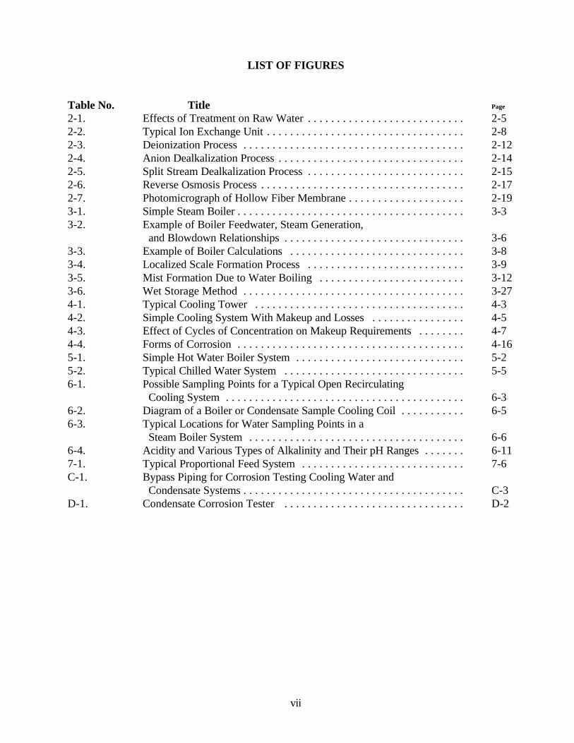
LIST OF FIGURES
Table No. Title Page
2-1. Effects of Treatment on Raw Water . . . . . . . . . . . . . . . . . . . . . . . . . . . 2-52-2. Typical Ion Exchange Unit . . . . . . . . . . . . . . . . . . . . . . . . . . . . . . . . . . 2-82-3. Deionization Process . . . . . . . . . . . . . . . . . . . . . . . . . . . . . . . . . . . . . . 2-122-4. Anion Dealkalization Process . . . . . . . . . . . . . . . . . . . . . . . . . . . . . . . . 2-142-5. Split Stream Dealkalization Process . . . . . . . . . . . . . . . . . . . . . . . . . . . 2-152-6. Reverse Osmosis Process . . . . . . . . . . . . . . . . . . . . . . . . . . . . . . . . . . . 2-172-7. Photomicrograph of Hollow Fiber Membrane . . . . . . . . . . . . . . . . . . . . 2-193-1. Simple Steam Boiler . . . . . . . . . . . . . . . . . . . . . . . . . . . . . . . . . . . . . . . 3-33-2. Example of Boiler Feedwater, Steam Generation,
and Blowdown Relationships . . . . . . . . . . . . . . . . . . . . . . . . . . . . . . . 3-63-3. Example of Boiler Calculations . . . . . . . . . . . . . . . . . . . . . . . . . . . . . . 3-83-4. Localized Scale Formation Process . . . . . . . . . . . . . . . . . . . . . . . . . . . 3-93-5. Mist Formation Due to Water Boiling . . . . . . . . . . . . . . . . . . . . . . . . . 3-123-6. Wet Storage Method . . . . . . . . . . . . . . . . . . . . . . . . . . . . . . . . . . . . . . 3-274-1. Typical Cooling Tower . . . . . . . . . . . . . . . . . . . . . . . . . . . . . . . . . . . . 4-34-2. Simple Cooling System With Makeup and Losses . . . . . . . . . . . . . . . . 4-54-3. Effect of Cycles of Concentration on Makeup Requirements . . . . . . . . 4-74-4. Forms of Corrosion . . . . . . . . . . . . . . . . . . . . . . . . . . . . . . . . . . . . . . . 4-165-1. Simple Hot Water Boiler System . . . . . . . . . . . . . . . . . . . . . . . . . . . . . 5-25-2. Typical Chilled Water System . . . . . . . . . . . . . . . . . . . . . . . . . . . . . . . 5-56-1. Possible Sampling Points for a Typical Open Recirculating
Cooling System . . . . . . . . . . . . . . . . . . . . . . . . . . . . . . . . . . . . . . . . . 6-36-2. Diagram of a Boiler or Condensate Sample Cooling Coil . . . . . . . . . . . 6-56-3. Typical Locations for Water Sampling Points in a
Steam Boiler System . . . . . . . . . . . . . . . . . . . . . . . . . . . . . . . . . . . . . 6-66-4. Acidity and Various Types of Alkalinity and Their pH Ranges . . . . . . . 6-117-1. Typical Proportional Feed System . . . . . . . . . . . . . . . . . . . . . . . . . . . . 7-6C-1. Bypass Piping for Corrosion Testing Cooling Water and
Condensate Systems . . . . . . . . . . . . . . . . . . . . . . . . . . . . . . . . . . . . . . C-3D-1. Condensate Corrosion Tester . . . . . . . . . . . . . . . . . . . . . . . . . . . . . . . D-2
PWTB 420-49-52 February 1998
1-1
Chapter 1
Introduction To Industrial Water Treatment
Section IIndustrial Water Treatment
Policy
1-1. Industrial water defined. Armypolicy requires in-house treatment of industrialwater systems using generic chemicals orformulated products that can be bid on ageneric basis from an approved watertreatment service company. The term"industrial water," as used here, means thewater used in Army heating, air conditioning,refrigeration, cooling, processing, and all otherequipment and systems that require water intheir operation. Industrial water is not thesame as potable water. Industrial water isnever to be consumed or used under situationsthat require a high degree of sanitation.Examples of industrial water applications are:boiler water (both steam and hot waterboilers); cooling water circulated throughcooling towers; evaporative condensers andevaporative coolers; diesel engine jacketwater; and chilled water for air conditioning.
1-2. Problems encountered in industrialwater systems. Problems found in industrialwater systems are often caused by deposits,scale, algae growths, fungi, slime, corrosion ofmetals, and deterioration of wood or otherparts of water-using equipment. Theseproblems generally result in reduced systemefficiency (higher operating costs), increasedequipment replacement costs and reducedsafety. At times they can be serious enough tocause complete system shutdown.
a. Deposits. Deposits are residues ofinsoluble materials, such as sludge, dirt, or
corrosion by-products, attached to pipe orequipment surfaces.
b. Scale. Scale is a specific type ofdeposit caused by precipitation of mineral saltsfrom water, and is very adherent to the pipe orequipment surface.
c. Algae, fungi, and slime. Algae aremicroscopic plants that may grow in variousindustrial water systems, but most commonlyappear on the distribution decks of coolingtowers. Fungi are living organisms that maydamage the wood parts of cooling towersthrough decay. Slimes are the accumulation ofthese biological contaminants and may foul theequipment.
d. Corrosion. Corrosion is thedeterioration of a material, usually a metal,because of a reaction with water.
1-3. Objective of industrial watertreatment. Industrial water is treated toprevent scale, corrosion and fouling, increaseefficiency, prolong life, and reduce repair andreplacement of water-using equipment. Thisrequires an adequate and continuous supply ofproperly treated makeup water, which isnormally from the installation's potable waterdistribution system. In addition, necessarysteps should be taken to provide a backupsupply. Every effort must be made toconserve water used in boilers, cooling towers,and other water-using equipment. Thisincludes identifying and fixing leaksthroughout the systems, minimizing boilerblowdown, reducing drift from cooling towers,and operating systems at the highestpermissible cycles of concentration. Using lesswater also reduces the amount of treatment
PWTB 420-49-52 February 1998
1-2
chemicals required. This, in turn, easesoperation of wastewater treatment facilitiesand reduces chemical handling and waste.
1-4. Responsibility for treatment.a. Office responsible. The Director of
Public Works (DPW) is responsible fortreating and testing industrial water.Approved treatment programs are provided inthis manual.
b. Organization assignments. Efficientand economical industrial water treatment andtesting requires specific organizationalassignments. The person assigned to industrialwater treatment and testing is often assignedother duties, therefore, coordinate time toensure that adequate and continuous attentionis given to industrial water treatment andtesting.
1-5. Unauthorized treatment.a. Unnecessary treatment. Treatment
of industrial water in excess of that which isrequired is unnecessary, expensive, and canlead to other problems. Chemicals authorizedfor treating water in one type of system are notnecessarily desirable and may actually bedetrimental in water intended for otherindustrial uses.
b. Use of premixed chemicals. The useof premixed proprietary chemicals in steamboilers is to be avoided. Such compounds,properly mixed for one type water, generallywill not work effectively with a different typewater. Since the compound is a fixed mixtureof chemicals, there is no way to adjust thedosage of individual chemicals to maintain theproper amount of each in the boiler.
c. Use of Nonchemical Devices. Manynonchemical devices sold for industrial watertreatment are purported to solve all waterrelated problems including scale, corrosion,
slime, and odor. They are said to achieveremarkable results through natural forces (suchas magnetism, electricity or radiation) eitherunknown to engineers or not disclosed. Oftenit is stated that the nonchemical devicesrequire little or no attention and no chemicals.Generally, they have not proven effective.Therefore, the use of these nonchemicaltreatment devices on Army systems eitherregularly or on a test evaluation basis, isprohibited.
1-6. Protecting health. Many of thechemicals used to treat industrial water may beharmful to the health of the operator and otherinstallation personnel, unless they are handledand controlled properly.
a. Protecting potable water supplies.Protection of potable water supplies as itapplies to an industrial water system issummarized as follows:
(1) A cross-connection is a physicalconnection between a potable water supplysystem and a nonpotable system (such as anindustrial water system) through whichcontaminated water can enter the potablewater system. Cross-connection must beavoided to maintain the safety of potable watersupplies. To prevent cross-connections wherepotable water is supplied to industrial watersystems, backflow prevention devices must beinstalled.
(2) Only Class III backflow preventiondevices (air gap or reduced pressure principledevices) are permitted between a potablewater supply system and an industrial watersystem which is from a source of nonpotablewater, or to which chemicals have been addedfor any purpose.
(3) If potable makeup water is suppliedto a tank or other type of open system, an airgap must be provided between the water inlet
PWTB 420-49-52 February 1998
1-3
and the maximum overflow level of the tank,device, or system.
b. Restrictions on direct steam use.Neutralizing amines added to protect thecondensate lines from corrosion makes thesteam and condensate unfit for consumption orother uses normally reserved for potablewater. Do not use treated steam in directcontact with food, heating of food trays, or forhumidification. For these applications usesteam-to-steam heat exchangers to provideamine-free steam. Guidance is provided in AR420-49, section 6-5.
c. Ban against sodium chromate.Sodium chromate, an excellent corrosioninhibitor, historically has been used extensivelyin the treatment of cooling towers and closedsystems. After it was identified as a humancarcinogen (cancer causing), theEnvironmental Protection Agency (EPA)prohibited its use in comfort cooling towersbecause of unacceptable health risks. Also,chromates have to be handled and disposed ofas hazardous materials. Army policy prohibitsthe use of chromates for treatment of industrialwater systems.
1-7. Record keeping requirements. Industrial water treatment and testingprocedures may vary from one installation toanother. This is because of the water qualityat the site and the type and size of the systems.These are governed by local factors, such asthe installation's mission, geographicallocation, and climate. Industrial watertreatment and testing logs and records shouldreflect the minimum entries needed for controlof the treatment program and for operatingrecords. Sampling and testing frequencies forvarious industrial water systems are providedin chapter 6.
a. Control charts. Develop control
charts showing the treatment chemicals used,the amount to add, the limits to maintain in thesystem, testing required, and the informationpeculiar to the system for the larger boilers andcooling towers.
b. Operating logs:(1) Large Steam and Water Boilers.
Keep boiler water treatment records on DAForm 4367 (Repair and Utilities OperationLog, Boiler Water Treatment) or an equivalentform. Logs should be maintained in plantsoperating above 15 psig steam or 30 psigwater with an output capacity above 3.5MBtu/hr or 100 horsepower. The logprovides a record of boiler, makeup andcondensate water treatment and test results.One log should be maintained for each boilerand one for plant makeup water data.
(2) Cooling Towers. Keep localorganized operating logs on all operatingcooling towers. These logs should containresults (including dates) of all chemical tests,calculated cycles of concentration, amounts ofchemicals added, and the amount of blowdownperformed.
(3) Other Systems. Local organizedoperating logs should also be kept for lowpressure steam boilers, high temperature hotwater (HTW), medium temperature hot water(MTW) and low temperature (LTW) boilers,and for closed chilled water systems. Theselogs should contain results (including dates) ofall chemical tests, amounts of chemicals added,and the amount of blowdown, whereapplicable.
c. Local records. Keep the maintenanceand history of industrial water treatment, otherthan that which must be entered on the logform or data accumulated for log form entries,in a historical record book for each system.
(1) This record should be at leastletter-size, and may be larger. It should be a
PWTB 420-49-52 February 1998
1-4
bound book, not a loose-leaf binder.(2) This record should contain a
historical record (including dates) of systemstart-up and shut-down, occurrences ofcorrosion and scale, major maintenanceperformed on the system, replacements ofpiping and equipment, accidents, outages,changes in methods of operation and treatmentused, and other pertinent data.
1-8. Support available:a. Boiler/Cooling water quality
assurance program. Army Regulation 420-49, Apr 97, section 6-4 requires samples fromcertain heating systems be submitted to anadequately equipped laboratory for analysis.The primary purpose for the check analysisprogram is to ensure that treatment chemicalconcentrations are, in fact, what the in-planttest results show. If in-plant tests are in error,the treatment levels in the boiler may be out ofcontrol limits, resulting in inefficient operationor damage to the boiler system. Waterchemistry limits that are out of control are amajor cause of boiler failures and damage.The contract laboratory, under contract toUSACPW (CECPW-ES), will provide thefollowing support:
(1) Perform analyses on water samplessubmitted from Army installations.
(2) Provide, on request, condensatecorrosion testers.
(3) Analyze test rings from condensatecorrosion testers after exposure.
(4) Analyze scale or deposit samplesfrom any industrial water system submittedfrom Army installations.
(5) Evaluate results of analyses andprovide to the submitting installation a writtenreport including appropriate technicalcomments and recommendations. In overseascommands where shipment of samples to the
United States is not feasible or expeditious,samples will be sent to a central laboratoryestablished by the command. Samplingrequirements under the check-analysisprogram are provided in chapter 6, paragraph6-1.
b. Other support. Matters concernedwith Army policy, request for staff visits totroubleshoot industrial water systems, trainingof water treatment personnel, and generaltechnical questions should be addressed toUSACPW, ATTN: CECPW-ES, Sanitary andChemical Division, 7701 Telegraph Rd..,Alexandria, VA 22315-3862.
Section IISafety And First Aid
1-9. Safety considerations. Chemicalsused in water treatment and relatedmaintenance activities range from highly toxicto mildly irritating to the persons handlingthem. Handle all water treatment and testingchemicals with care, following any specialinstructions prescribed by the manufacturer.Keep areas where chemicals are handled orstored clean and free of debris to minimize thechances for accidents. Personnel handlingthese chemicals should attend educationalsessions, refer to material safety data sheets(MSDS's) for additional information, and useproper respirators and protective equipmentrecommended by the installation environmentalengineer.
a. Handling acid. Avoid splashing acid.If acid does contact the eyes, skin, or evenclothing, flush immediately with water. Referall cases of acid burns, especially to the eyes,to a doctor. When diluting any acid, never addwater to the acid because this may cause aviolent reaction or splattering. Always pouracid into the water. Wear Occupational Safety

PWTB 420-49-52 February 1998
1-5
and Health Agency (OSHA) approvedgoggles, face shield, rubber gloves, and arubber apron when handling acid.
b. Handling caustic soda (sodiumhydroxide). Caustic soda is a strong alkalithat can cause severe burns when contacted ineither the liquid or solid form. If caustic sodadoes contact the eyes, skin, or even clothing,flush immediately with water. When water isadded to caustic soda, a great deal of heat maybe generated which can cause splattering orboiling of the solution. The dust or mist fromcaustic soda may cause injury to the upperrespiratory tract if inhaled. When handlingcaustic soda wear close fitting OSHAapproved industrial goggles, rubber aprons andgloves, and coveralls that fit snugly at the neckand wrist.
c. Handling other chemicals. Many ofthe other chemicals used in water treatment,including amines, soda ash, lime, sodiumaluminate, sulfite, biocides, and algicides, maycause some irritation on contact with the skin.Handle all chemicals with caution, followingthe manufacturer's recommendations.Immediate flushing with water is generallyrecommended for any contact of a chemicalwith the skin. Review the material safety datasheets (MSDSs) that are available for thechemicals being handled for any specialprecautions that should be taken.
d. Chemical spill kits. Each area whereacids, caustic soda, or other hazardousmaterials are used or stored must be equippedwith appropriate chemical spill kits. Kits forcleaning up acids, bases, and solvents arecommercially available. It is best to beprepared for a spill that never happens.
1-10. First aid information:a. Eyewash fountain. An eyewash
fountain or a ready source of running tap
water (a bubbler drinking fountain or hosewith a soft flow of water) must be readilyavailable to wash out or flush the eyes. If evenminute quantities of acid or caustic soda enterthe eyes, immediately flush the eyes with largeamounts of water for at least 15 minutes.
b. Safety shower. A readily accessible,well marked, rapid-action safety shower mustbe in the area where acid or caustic soda isbeing handled.
c. Safety inspection. Regularly inspectall safety equipment to ensure it is in goodworking condition. Operate safety shower andeyewash weekly to prevent accumulation ofrust. Place clearly marked signs containingconcise instructions on their use near theemergency eyewash fountain and the safetyshower.
Section IIIDisposal Of Industrial Water
Wastes
1-11. Disposal procedures. Coordinate thetreatment and disposal of liquid and solid(sludge) wastes from industrial systems withthe installation environmental engineer(coordinator).
a. New chemicals. The use of a newwater treatment chemical must be reviewed byan environmental engineer to determine if itcan be safely disposed of by the existingprocedure or if new procedures must bedeveloped.
b. Discharge pretreatment. Pretreatment of water discharges refers to atreatment procedure that is applied to thewater before it is discharged to the basetreatment systems. The installationenvironmental engineer is responsible fordetermining when pretreatment is required andwhat methods are to be used.
PWTB 420-49-52 February 1998
1-6
c. Discharge requirements. Thedischarge of industrial water treatment systemwastes may be regulated by the installationenvironmental engineer. The discharge may becontrolled in the following ways:
(1) The location of the dischargeshould be set by the configuration of the watertreatment system and available sewers. Thelocation of discharge for occasional dischargesshould be established through the installationengineer. Normal practice may includedischarge into either the sanitary or industrialwastewater treatment system.
(2) The maximum rate of discharge tothe designated sewer system should beestablished through the installationenvironmental engineer. There are two factorsof importance in setting a maximum rate: thehydraulic capacity of the sewer, and thestrength (chemical concentration) of the waste.
(3) The time when a discharge isallowed from a water treatment system unitmay be established by the installationenvironmental engineer.
1-12. Regulations that may apply:a. Installation directives.
The water treatment system operator isresponsible for complying with the proceduresand policies established at the installation,including the directives on waste disposal fromthe installation environmental engineer. Thecompliance of the installation directives withgovernment environmental regulations is theresponsibility of the installation environmentalengineer.
b. Environmental regulations.There are numerous environmental regulationsthat may apply at the installation level. Thesehave been established by law. Currentregulatory information is available from the
installation environmental engineer.(1) Toxic Substances Control Act
authorizes the US Environmental ProtectionAgency (EPA) to control all new and existingchemical substances determined to causeunreasonable risk to the public health orenvironment.
(2) Clean Water Act (CWA) includesthe Federal Water Pollution Control Act andamendments. The CWA establishes limits forthe discharge of pollutants to navigable waters,regulations on specific toxic pollutants inwastewater discharges, and control of oil andhazardous substance discharges.
(3) Safe Drinking Water Act providesfor protection of underground sources ofdrinking water and establishes primary andsecondary drinking water standards.
(4) Federal Insecticide, Fungicide, andRodenticide Act requires that all pesticides beregistered with the U.S. EPA.
(5) Resources Conservation andRecovery Act (RCRA) addresses the controlof solid waste. Defined hazardous wastes arecontrolled under RCRA by a complex manifestsystem designed to track a waste from itsgeneration to final disposal.
(6) Occupational Safety and HealthAct establishes health and safety requirementsfor the work place including handling andlabeling requirements, safety precautions, andexposure limits to work place contaminants.
(7) Comprehensive EnvironmentalResponse, Compensation, and Liability Act(also commonly referred to as Superfund)establishes the responsibilities and proceduresfor the response to existing uncontrolledhazardous waste sites.
PWTB 420-49-52 February 1998
2-1
Chapter 2
Makeup Water
Section IGeneral Information
2-1. Industrial water. Industrial water systems at most Armyinstallations use recirculating water systems.Fresh water added to replace water lost byblowdown, evaporation, wind drift, leaks, orwithdrawal in these systems is referred to asmakeup.
2-2. Sources of makeup water. The usualsource of makeup water is the installation'spotable water supply. This represents atreated water that usually is of a very uniformquality on a day-to-day basis. Other sourcesof makeup water could include well water,surface water, or holding ponds that are nottreated to the extent that the potable watersource is treated. The quality of this makeupwater may vary slightly, depending on itssource.
a. Groundwater. Groundwater generallycontains high dissolved minerals but are moreuniform in quality. Where the groundwater istreated before use by a system, there may besome fluctuations in quality due to variationsin treatment efficiency.
b. Surface water. Surface water suppliesmay vary with the season and also the weather,with higher turbidity and suspended solidspossible during wet weather. Where thesewaters are treated, the quality generally will bemore uniform than for untreated surfacewaters.
2-3. Source selection factors to consider.The source of water used in industrial water
systems should be both reliable and uniform inquality. There should also be a backup sourceavailable to the operator.
2-4. Reasons and criteria for treatingmakeup water:
a. Reason for treating makeup water.Makeup water is treated to remove or reducethe concentration of any undesirable impurity.This may include impurities that will causecorrosion in the industrial water system, createa deposit or scale in the system, or otherwiseinterfere with the operation of the system.
b. Criteria for treating makeup water:(1) Cooling towers. Because
impurities do not become highly concentrated,pretreatment of makeup water for coolingtowers is normally not required. Specialconditions may require treatment.
(2) Steam boilers. Water softeners(usually "zeolite" units) should be installed atboiler plants. New steam boilers normallyrequire makeup water with less than 1 ppmhardness, however, the manufacturer'srecommendations should be followed.
(3) Hot water systems. Softening isrecommended for high-temperature, high-pressure hot water systems when the totalhardness of the makeup water exceeds 10 ppm(as CaCO3).
(4) Other systems. Softening ofmakeup water is generally recommended inchilled water systems, dual purpose (hot orchilled) systems, and in hot water boilerstreated with nitrite-borax, or molybdates if themakeup water total hardness exceeds 250 ppm(as CaCO3). Makeup water in hot waterboilers treated with sodium sulfite and caustic
PWTB 420-49-52 February 1998
2-2
soda, and diesel jacket systems should besoftened when its total hardness exceeds 50ppm (as CaCO3).
c. Measurement of makeup water. Makeup rates are required to calculate properoperating data on cooling towers and steamboilers. They may be estimated by recordingthe time it takes to fill a container of knownvolume, or preferably, measured with aappropriate makeup meter to provide moreaccurate values and to reduce laborrequirements.
Section IIMethods Of Treatment
2-5. General discussion. Treatment ofindustrial water falls into two categories -external treatment and internal treatment.External treatment involves the pretreatmentof makeup water to remove hardness,alkalinity, dissolved gases, or other impuritiesbefore the water enters the particular watersystem, e.g., steam boiler, cooling tower,closed hot or chilled system. Internaltreatment involves the introduction ofchemicals directly into the water system.Some waters may require one or bothmethods.
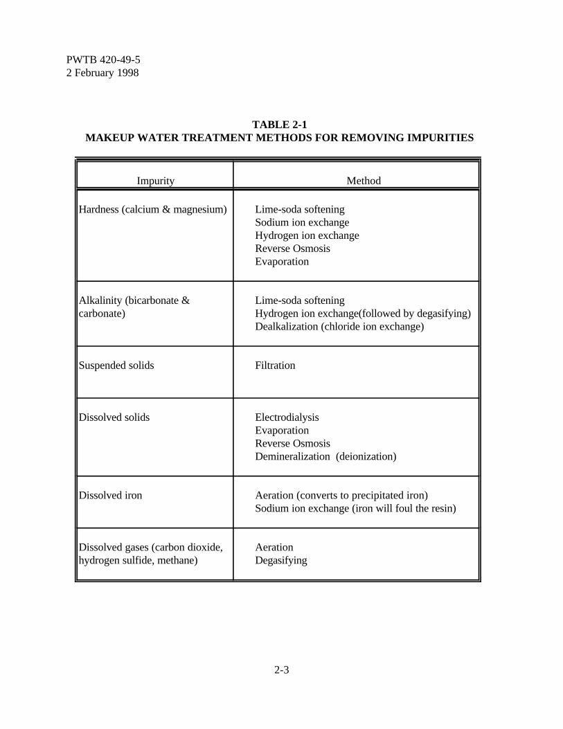
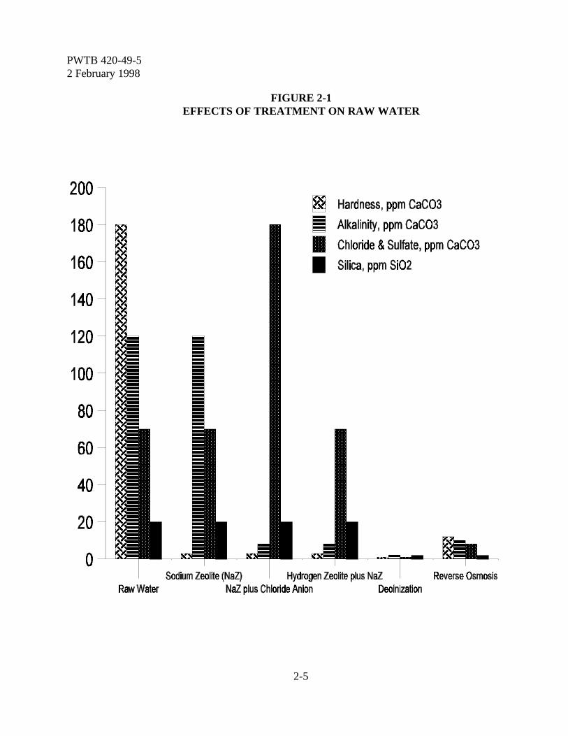
a. External treatment. External treatmentequipment and chemicals are available toremove impurities from the makeup waterbefore they enter the internal system.Removing impurities before they enter asystem, particularly a steam boiler, is the mosteffective way to protect the system, to reducewater problems, and to improve operatingefficiency. The treatment methods andequipment required are determined by theimpurities that need to be removed from themakeup water. Various external treatmentmethods available to remove typical impurities
found in makeup water are shown in table 2-1.The effects of these treatment methods on rawwater are illustrated in figure 2-1. Treatmentmay be applied to only a part of the makeupwater which is then blended with raw(untreated) water to achieve a desired quality.This is known as split stream treatment.External treatment methods are brieflydescribed in paragraph 2-6 through 2-18.External water treatment is generally requiredfor only steam boilers and high temperaturehot water (HTHW) systems, but may bejustified for use in other industrial watersystems as well. Although several types oftreatment may be available, sodium zeolitesoftening (ion exchange) is the most commonmethod used at Army installations for treatingmakeup water. A guide for selecting externaltreatment methods/equipment for steam boilersis provided in table 2-2.
b. Internal treatment. The purpose ofinternal treatment is to prevent any problemsin the internal water system that might becaused by the impurities remaining afterexternal treatment. Essentially all industrialwater systems require internal water treatment.Internal water treatment methods approved foruse on Army installations are covered inchapters 3, 4, and 5.
2-6. Aeration. Some waters, in particularwell water, contain low levels of dissolved iron(1 to 5 ppm). Although these quantities seemsmall, they will produce voluminousprecipitates when they come in contact withair. If these precipitates are deposited in lines,they will restrict flow. When deposited in heatexchangers, they will restrict heat transfer.Iron in the makeup water can be removed bycontact with air to cause it to precipitate, andthen by removing the precipitate by filtration.
a. Aerators are usually of the coke tray or
PWTB 420-49-52 February 1998
2-3
TABLE 2-1MAKEUP WATER TREATMENT METHODS FOR REMOVING IMPURITIES
Impurity Method
Hardness (calcium & magnesium) Lime-soda softeningSodium ion exchangeHydrogen ion exchangeReverse OsmosisEvaporation
Alkalinity (bicarbonate &carbonate)
Lime-soda softeningHydrogen ion exchange(followed by degasifying)Dealkalization (chloride ion exchange)
Suspended solids Filtration
Dissolved solids ElectrodialysisEvaporationReverse OsmosisDemineralization (deionization)
Dissolved iron Aeration (converts to precipitated iron)Sodium ion exchange (iron will foul the resin)
Dissolved gases (carbon dioxide,hydrogen sulfide, methane)
AerationDegasifying

PWTB 420-49-52 February 1998
2-4
TABLE 2-2GUIDE FOR SELECTION OF EXTERNAL TREATMENT EQUIPMENTMakeup
RequirementsSteam
PressureAlkalinity Turbidity Recommended External
Treatment Equipment
G.P.M. PSIG PPM-CaCO3 PPM
All Less than 15 All Less than 10 Normally internal treatment only.
Over 10 Filtration plus internal treatment.
Less than 100 15-200 Less than 75 Less than 10 Sodium zeolite.
Over 10 Filtration plus sodium zeolite.
Over 75 Less than 10 1.Sodium zeolite plus hydrogen zeolite (3).2.Sodium zeolite plus chloride/anion exchange.3.Hydrogen zeolite (3,5).
Over 10 1.Filtration plus sodium zeolite plus hydrogen zeolite.2.Hydrogen zeolite (3,5).
200-650 Less than 35 Less than 10 Sodium zeolite.
Over 10 Filtration plus sodium zeolite.
Over 35 Less than 10 1.Sodium zeolite plus hydrogen zeolite (3).2.Demineralization.
Over 10 1.Filtration plus sodium zeolite plus hydrogen zeolite.2.Filtration plus demineralization.
Over 100 15-200 Less than 75 Less than 10 Sodium zeolite.
Over 10 1.Filtration plus sodium zeolite.2.Hot-lime soda.
Over 75 Less than 10 Sodium zeolite plus hydrogen zeolite (3).
Over 10 1.Filtration plus sodium zeolite plus hydrogen zeolite(3).2.Filtration plus demineralization.
200-650 All Less than 10 1.Sodium zeolite plus hydrogen zeolite (3).2.Demineralization.
Over 10 1.Filtration plus sodium zeolite plus hydrogen zeolite(3).2.Filtration plus demineralization.3.Hot-lime hot-sodium zeolite. Above psig.
All Over 650(Normallysuperheated)
All Less than 10 Demineralization.
10-400 Filtration plus demineralization.
Over 400 1.Filtration plus demineralization.2.Reverse osmosis.3. Electrodialysis.
NOTES1. The above chart provides general guidelines only. Final choice of treatment system must be based upon complete raw water analysis, feedwater requirements, and overall
economics, including both external and internal treatment and blowdown. External treatment may be desirable to reach recommended levels of TDS without exceedingother parameter limits for causticity, silica, or suspended solids.
2. Separate deaeration is required to all boilers over 15 psig pressure, except where lime-soda softeners are designed to provide adequate deaeration as well as softening.3. Degasification is required after hydrogen zeolite treatment.4. Filtration process may require clarification and aeration.5. Flows less than 10 g.p.m. or very low sulfate plus chloride content.
PWTB 420-49-52 February 1998
2-5
FIGURE 2-1EFFECTS OF TREATMENT ON RAW WATER
PWTB 420-49-52 February 1998
2-6
wood slat design. Coke tray aerators consistof a series of coke-filled trays through whichthe water percolates. Aeration is suppliedduring the percolation and the free fall fromone tray to the next. Wood slat aerators aresimilar to small atmospheric cooling towerswith the slats staggered to break the free fall ofthe water and, therefore increase the surfacecontact with air. Wood slat aerators can alsobe equipped with a forced draft fan to increasetheir efficiency.
b. In addition to oxidizing iron, aerationcan also remove undesirable dissolved gasessuch as carbon dioxide, hydrogen sulfide, andmethane.
2-7. Filtration:a. Standard filtration. Suspended solids
in makeup water can be removed by filtration.These solids may include soluble iron that hasbeen precipitated or residual calcium carbonateparticles. These solids must be removed fromthe feed to ion exchange units or reverseosmosis units.
(1) A typical filter is a bed of sand oranthracite below a set of distribution headersand resting on a support of coarse rock.Below the bed is the collection header throughwhich the clarified water is drawn. Waterflows through the filter bed either by gravity orby pressure.
(2) The sand or anthracite does notactually remove the suspended solids. Instead,a layer of suspended solids is laid down on topof the bed and this layer of filter cake does theactual removal.
(3) As the thickness of the filter cakebuilds up, the water flow decreases. When theflow becomes too small to be useful, the waterflow is reversed and the filter is backwashed toremove the buildup of suspended solids. Thefilter is then returned to service and the cyclerepeated.
(4) Filtration rates are typically 3gallons per minute per square foot(gal/min/ft2). Backwash rates are 12 to 15gal/min/ft2 for sand filters and 8 to 12gal/min/ft2 for anthracite filters.
2-8. Lime-soda softening. The lime-sodaprocess is a common method of treating waterfor potable and industrial uses.
a. Hydrated lime (calcium hydroxide) andsoda ash (sodium carbonate), added to thewater in a reaction tank, reduces hardness dueto calcium and magnesium by precipitation.The solids formed are allowed to settle forremoval as a water sludge. The settled wateris passed slowly from the tank and filtered foruse as makeup.
b. The addition of lime and soda ash atnormal temperature is referred to as the coldlime-soda process. There also is a processwhere the lime and soda ash are reacted withthe water at temperatures greater than 212degrees Fahrenheit (oF), called the hot lime-soda process. This is used to remove a greateramount of the hardness in water.
2-9. Ion exchange process - general. Ionexchanger units (water softeners) are usedextensively at Army installations. An ionexchanger is a vessel containing several cubicfeet (ft3) of ion exchange material resting upona gravel support. The direction of water flowis down. Most Army units operate underpressure, but gravity flow units are available.Flow rates vary with the make of equipmentbut are in the range of 6 to 8 gal/min/ft2 of ionexchange material surface. The type of ionexchange materials determines the type ofsystem. A backup ion exchange unit and surgetank are typically included in these systems topermit an uninterrupted supply of softenedwater. The manufacturer's recommendationsshould be posted near the softening unit. A
PWTB 420-49-52 February 1998
2-7
typical ion exchanger unit is illustrated infigure 2-2.
2-10. Sodium ion exchange. The Softening process used on most Armyinstallations is sodium ion exchange. It ispreferred to other softening processes becauseit is compact, easy to operate, relativelyinexpensive and produces a suitable makeupwater for industrial water systems.
a. Service cycle. This is the normaloperating cycle during which hardness isremoved from the makeup water flowingthrough the softener.
(1) The sodium ion exchange processdepends upon the exchange of sodium ionsfrom certain minerals and synthetic ionexchange resins for calcium and magnesiumions in the water.
Ca(HCO3)2 + Na2Z v Ca Z + 2NaHCO3
Calcium Sodium Calcium SodiumBicarbonate Zeolite Zeolite Bicarbonate
(2) The softening capability of an ionexchange material is usually given in kilograinsper cubic foot (kgr/ft3). A kilograin is 1,000grains and there are 7,000 grains in a pound.The volume of water that a given ion exchangematerial can soften is determined by thecapacity of the material and the hardness in thewater.
Example 2-1:1. The capacity of ion exchange material is
20 kgr/ft3. (That means that one cubicfoot of it can remove 20,000 grains ofhardness from water.) The water beingtreated has 257 ppm hardness.
2. How much will it treat? (17.1 ppmequals one grain per gallon)
Capacity, kgr/ft3
Removal = _________________ x 1,000 x 17.1 Hardness, ppm
20,000 = ________ x 17.1 = 1,331 gal/ft3
257
(3) The operator needs to know howmuch water can be softened beforeregeneration is necessary. This can beestimated by multiplying the cubic feet of ionexchange material by the number of gallonseach cubic foot can soften.
Example 2-2:1. There are 10 cubic feet of material in the
ion exchanger in example 2-1.2. Since each cubic foot can soften 1,331
gallons, then 10 x 1,331 = 13,310gallons can be softened before thematerial is completely spent.
(4) In practice, it is necessary to checkthe outlet water at regular intervals. Thehardness of the outlet water should be lessthan 1 ppm. When the hardness approximates1 ppm, the material must be regenerated.
b. Regeneration cycle. The regenerationcycle is a number of steps during which thesoftener is taken off line, backwashed, theresin regenerated and then rinsed.
(1) When the spent ion exchangematerial or calcium zeolite is in contact with astrong salt solution, the material is regeneratedby the calcium being exchanged for sodium.
CaZ + 2NaCl 6 Na2Z + CaCl2
Calcium Sodium Sodium CalciumZeolite Chloride Zeolite Chloride
The completeness of regeneration dependsupon the strength of the salt solution (brine)used. After the material is regenerated, it canbe used again to remove hardness from water.
(2) Before the bed is regenerated, itmust be backwashed by flowing water frombottom to top. The flow rate must be

PWTB 420-49-52 February 1998
2-8
FIGURE 2-2TYPICAL ION EXCHANGE UNIT

PWTB 420-49-52 February 1998
2-9
adequate to remove any suspended solidswhich have been caught on top of the bed.The bed will need to expand by about 50percent due to the backwash flow rate. Therate should be controlled so that it will notsweep ion exchange material out of thesoftener into the lines. A backwash rate of 4to 6 gal/min/ft2 of bed surface for about 10minutes is normal, but the manufacturer'srecommendations should be followed.
(3) Next comes the brining. A 10percent solution of salt brine is slowly addeddownflow at a rate of 0.5 to 1.0 gal/min/ft3 ofbed volume for about 30 minutes. Rock salt ispreferred to granulated salt because it is just aseffective and less prone to cake. Someinstallations may start with concentrated brinewhich must be diluted. The salt required andthe capacity regenerated is shown for a typicalresin in table 2-3. However, themanufacturer's instructions should befollowed, if available.
(4) A slow rinse follows the brining.One to three bed volumes of freshwater areused to remove the brine from the bed. This isequal to 7.5 to 22.5 gal/ft3 of bed volume.
(5) Finally, a fast rinse is used toremove any traces of the regenerant. This isdone at a rate of 1.5 to 2.0 gal/min/ft3 of bedvolume until the discharge is free of hardness;35 to 100 gal/ft3 of bed volume is required.
(6) The unit is now ready for anotherservice cycle.
c. Testing and record keeping.Feedwater should be tested for hardnessweekly and the outlet water should be testedfor hardness every shift (3 times a day) forsystems that require frequent regeneration.Accurate records should be kept of these testsalong with the gallons of water treated duringeach service cycle, and the salt used duringeach regeneration cycle.
d. Operating problems. There are several
common problems sometimes encounteredwith softener operation.
(1) There will be a normal decrease incapacity of about 5 percent per year. Anydecrease greater than this should beinvestigated. Incomplete softening is anotherindication of trouble.
(2) A common cause of capacity loss isiron fouling. Soluble iron will exchange forsodium during the service cycle, but sodiumwill not exchange for iron during theregeneration cycle. There is a simple test todetermine iron fouling. A pinch of iron-fouledion exchange material added to 10 percenthydrochloric acid in a test tube will cause thehydrochloric acid to turn yellow.
(a) An iron-fouled material may betreated with dilute hydrochloric acid or sodiumhydrosulfide. This procedure is followed by astandard brine regeneration.
(b) Check the manufacturer'srecommendations before using the aboveregeneration procedure. Do not attempt witha galvanized or unlined steel tank. The tankmust be all reinforced plastic or rubber, orplastic lined with no breaks in the lining.
(3) Improper backwash is the othercommon cause of trouble. Too high abackwash rate can wash the ion exchangematerial out of the unit. The bed depth can bechecked by probing with a steel rod until theunderdrain material can be felt. Normal beddepth is usually 30 to 36 inches. The bedvolume in cubic feet (ft3) can be calculated bythe following formula:
Volume, ft3 = (Radius, ft)2 x (Depth, ft) x 3.14
(a) Check the bed depth at 10 pointsand use the average value. If there is muchdifference in the thickness of different points(say as much as 15 percent), channeling can beoccurring. This can be caused by too low a
PWTB 420-49-52 February 1998
2-10
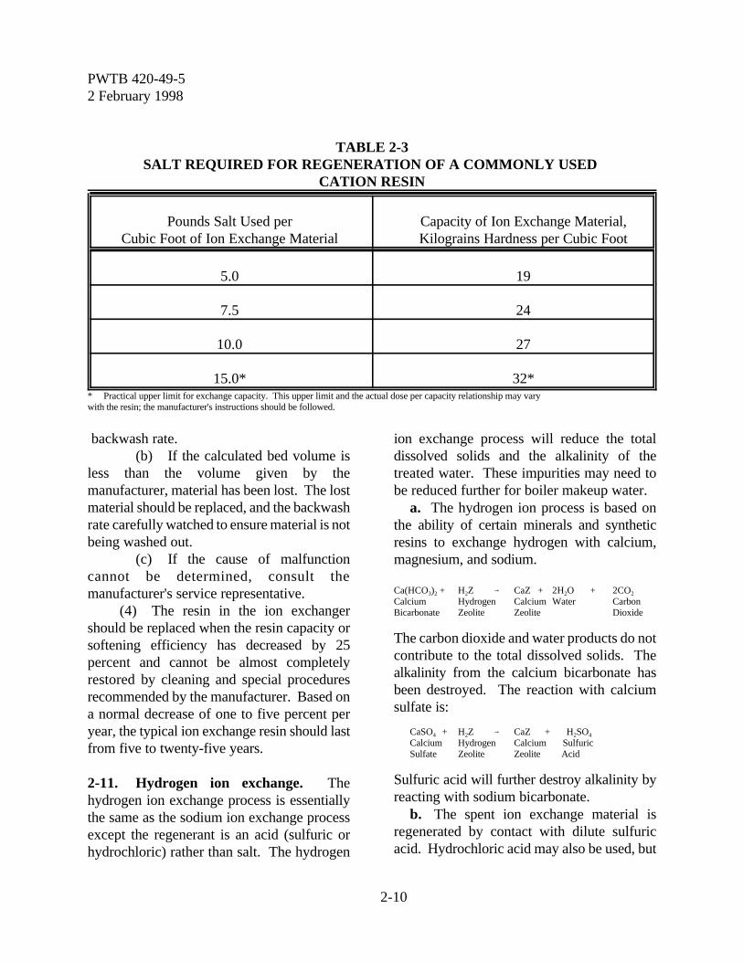
TABLE 2-3SALT REQUIRED FOR REGENERATION OF A COMMONLY USED
CATION RESIN
Pounds Salt Used perCubic Foot of Ion Exchange Material
Capacity of Ion Exchange Material,Kilograins Hardness per Cubic Foot
5.0 19
7.5 24
10.0 27
15.0* 32** Practical upper limit for exchange capacity. This upper limit and the actual dose per capacity relationship may vary with the resin; the manufacturer's instructions should be followed.
backwash rate.(b) If the calculated bed volume is
less than the volume given by themanufacturer, material has been lost. The lostmaterial should be replaced, and the backwashrate carefully watched to ensure material is notbeing washed out.
(c) If the cause of malfunctioncannot be determined, consult themanufacturer's service representative.
(4) The resin in the ion exchangershould be replaced when the resin capacity orsoftening efficiency has decreased by 25percent and cannot be almost completelyrestored by cleaning and special proceduresrecommended by the manufacturer. Based ona normal decrease of one to five percent peryear, the typical ion exchange resin should lastfrom five to twenty-five years.
2-11. Hydrogen ion exchange. Thehydrogen ion exchange process is essentiallythe same as the sodium ion exchange processexcept the regenerant is an acid (sulfuric orhydrochloric) rather than salt. The hydrogen
ion exchange process will reduce the totaldissolved solids and the alkalinity of thetreated water. These impurities may need tobe reduced further for boiler makeup water.
a. The hydrogen ion process is based onthe ability of certain minerals and syntheticresins to exchange hydrogen with calcium,magnesium, and sodium.
Ca(HCO3)2 + H2Z 6 CaZ + 2H2O + 2CO2
Calcium Hydrogen Calcium Water CarbonBicarbonate Zeolite Zeolite Dioxide
The carbon dioxide and water products do notcontribute to the total dissolved solids. Thealkalinity from the calcium bicarbonate hasbeen destroyed. The reaction with calciumsulfate is:
CaSO4 + H2Z 6 CaZ + H2SO4
Calcium Hydrogen Calcium SulfuricSulfate Zeolite Zeolite Acid
Sulfuric acid will further destroy alkalinity byreacting with sodium bicarbonate.
b. The spent ion exchange material isregenerated by contact with dilute sulfuricacid. Hydrochloric acid may also be used, but

PWTB 420-49-52 February 1998
2-11
no other acid.
CaZ + H2SO4 6 H2Z + CaSO4
Calcium Sulfuric Hydrogen CalciumZeolite Acid Zeolite Sulfate
c. The hydrogen ion exchanger is much thesame as the sodium ion exchanger, except thatthe tank is made of or lined with acid resistantmaterial.
d. The regeneration cycle is also much thesame, except that sulfuric acid is used insteadof salt. Before using sulfuric acid, be sure toreview available information on safety and firstaid. Handling and safety instructions shouldbe posted near sulfuric acid equipment.
e. Troubleshooting is also much the same,although iron fouling does not occur inhydrogen ion exchangers.
f. The outlet water is acidic and cannot bedirectly used as boiler makeup. The water canbe mixed with the outlet of a sodium ionexchanger. The acid in the hydrogen ionexchange water will be neutralized and at thesame time a portion of the alkalinity in thesodium ion exchange water is destroyed. Theproportion of the water mix depends upon theanalysis of the water being treated, buttypically it is approximately half and half.
g. Carbon dioxide is produced in thehydrogen ion exchange process and is alsoproduced when the water from hydrogen andsodium ion exchange is mixed. It can beremoved from the water in a degasifier or adeaerator.
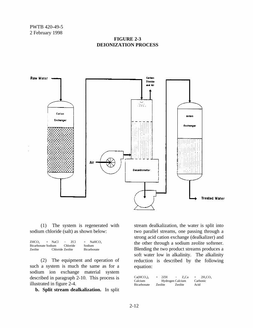
2-12. Anion exchange. Sodium andhydrogen ion exchangers remove the positivelycharged ions (cation exchange). Ion exchangematerials also have been developed whichremove negatively charged ions (anionexchange). Demineralization uses both cationand anion exchange to remove all ions fromthe water. A typical deionization process isillustrated in figure 2-3.
a. The cation exchange is described in
paragraphs 2-10 and 2-11. The anionexchange reactions involve:
H2SO4 + Z(OH)2 6 2H2O + ZSO4
Sulfuric Hydroxyl Water SulfateAcid Zeolite Zeolite
b. The spent ion exchange material (ZSO4)is regenerated with sodium hydroxide(caustic).
ZSO4 + 2NaOH 6 Z(OH)2 + Na2SO4
Sulfate Sodium Hydroxyl SodiumZeolite Hydroxide Zeolite Sulfate
c. When the anion exchange is combinedwith hydrogen exchange, the resulting waterwill contain no minerals. It has becomedeionized (also referred to as demineralized).
CaSO4 + H2Z 6 CaZ + H2SO4
H2SO4 + Z(OH)2 6 2H2O + ZSO4
d. The two reactions can take place inseparate vessels (a "two bed" deionizer), or thetwo ion exchange materials can be combined ina single vessel (a "mixed bed" deionizer).
e. The deionization process has limitedapplication at an Army installation. It isrequired mainly for high pressure boilers.
2-13. Dealkalization:a. Anion dealkalization. It may be
necessary to treat water with a low hardnessand high alkalinity to reduce the alkalinitybefore it is used in boilers. There is an anionexchange process called anion dealkalizationwhich will remove alkalinity and also removesulfates and nitrates. In almost all cases, theanion dealkalizer should follow a softener. Bicarbonate is exchanged for chloride asillustrated by the following reaction:
NaHCO3 + ZCl 6 NaCl + ZHCO3
Sodium Chloride Sodium BicarbonateBicarbonate Zeolite Chloride Zeolite
PWTB 420-49-52 February 1998
2-12
FIGURE 2-3DEIONIZATION PROCESS
(1) The system is regenerated withsodium chloride (salt) as shown below:
ZHCO3 + NaCl 6 ZCl + NaHCO3
Bicarbonate Sodium Chloride SodiumZeolite Chloride Zeolite Bicarbonate
(2) The equipment and operation ofsuch a system is much the same as for asodium ion exchange material systemdescribed in paragraph 2-10. This process isillustrated in figure 2-4.
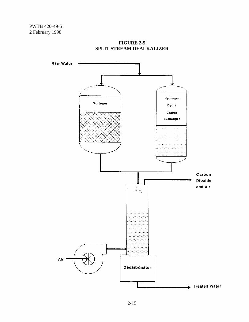
b. Split stream dealkalization. In split
stream dealkalization, the water is split intotwo parallel streams, one passing through astrong acid cation exchange (dealkalizer) andthe other through a sodium zeolite softener.Blending the two product streams produces asoft water low in alkalinity. The alkalinityreduction is described by the followingequation:
Ca(HCO3)2 + 2ZH 6 Z2Ca + 2H2CO3
Calcium Hydrogen Calcium CarbonicBicarbonate Zeolite Zeolite Acid
PWTB 420-49-52 February 1998
2-13
The carbonic acid dissociates into CO2 andH2O. The CO2 must be released into theatmosphere.
(1) The cation exchange resin alsoreacts with sodium, calcium and magnesiumchlorides, sulfates and nitrates, and other saltsto produce free mineral acids (FMA). pHadjustment is necessary to balance alkalinitywith acidity (FMA) to form neutral water.
(2) The system is regenerated withsulfuric acid as shown below:
CaZ + H2SO4 6 H2Z + CaSO4
Calcium Sulfuric Hydrogen CalciumZeolite Acid Zeolite Sulfate
(3) The exchanger tank is made of orlined with an acid resistant material.
(4) Since blending also produces CO2,a decarbonator is normally used to reduce CO2
concentration to 5-10 ppm or less. A typicalsplit stream process is shown in figure 2-5.
2-14. Decarbonation. Carbon dioxide isproduced during hydrogen exchange and alsowhen the waters from hydrogen ion exchangeand sodium ion exchange are mixed. Carbondioxide dissolved in water can cause corrosionin water lines, pump impellers, and vessels. Asdiscussed in chapter 3, carbon dioxide must bekept as low as possible in boiler water andsteam condensate lines.
a. Free carbon dioxide is commonlyremoved in a degasifier, which is a woodenvessel through which the water trickles overslats or packing. Air is blown into the bottomof the vessel and strips out the carbon dioxide.In steam and high temperature water systems,removal of the CO2 is achieved in thedeaerator rather than with a separate degasifierunit. This changes a portion of thebicarbonate alkalinity in the makeup water tocarbonate alkalinity and increases the pH.
b. By analyzing for the hydrogen ionconcentration (pH) and total alkalinity (M) ofa water, the free carbon dioxide content can be
estimated from table 2-4.
2-15. Evaporation. In this process, wateris heated to produce relatively pure vapor,which is then condensed and used for boilerfeed. Evaporators are of several differenttypes, the simplest being a tank of waterthrough which steam coils are passed to heatthe water to the boiling point. To increaseefficiency, the vapor from the first tank maypass through coils in a second tank of water toproduce additional heating. Another type ofevaporator operates under a partial vacuumcausing a lowering of the boiling point ofwater and evaporation at lower temperatures.Evaporators may be economical where steamas a source of heat is readily available. Theyalso have an advantage over deionization whenthe dissolved solids in the raw water are veryhigh.
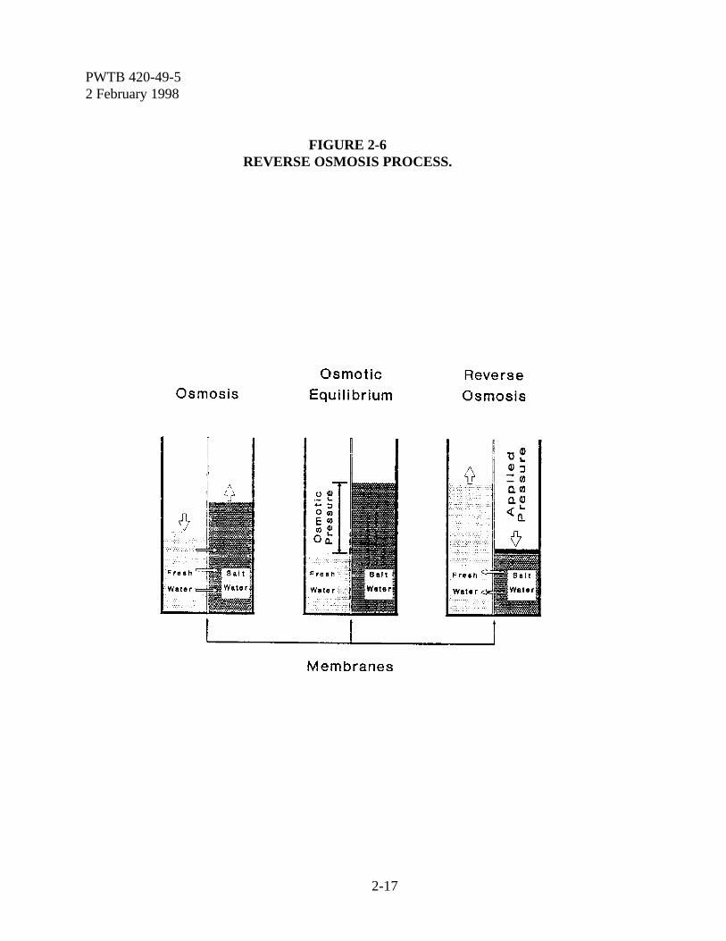
2-16. Reverse osmosis. If salt water anddistilled water are separated by a semi-permeable membrane, the distilled water willtend to diffuse through the membrane to thesalt water. This flow is in one direction-fromthe more dilute to the more concentrated. Thedistilled water will continue to permeatethrough the membrane until equilibrium isestablished and both waters will be salty. Thedirection of flow is determined by the osmoticpressure of the system. If a pressureexceeding the osmotic pressure is exerted onthe salt water side of the membrane, the flowwill be reversed and distilled water can beproduced from salt water. This process isllustrated in figure 2-6.
a. Pretreatment. Material that canpotentially foul the membrane will interferewith the process and must be removed bypretreatment. Foulants include suspended andcolloidal solids, iron, metal oxides, scale, andbiological materials.

PWTB 420-49-52 February 1998
2-14
FIGURE 2-4ANION DEALKALIZATION PROCESS
PWTB 420-49-52 February 1998
2-15
FIGURE 2-5SPLIT STREAM DEALKALIZER
PWTB 420-49-52 February 1998
2-16
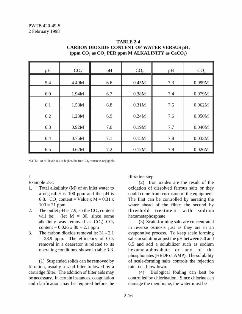
TABLE 2-4CARBON DIOXIDE CONTENT OF WATER VERSUS pH.
(ppm CO2 as CO2 PER ppm M ALKALINITY as CaCO3)
pH CO2 pH CO2 pH CO2
5.4 4.40M 6.6 0.45M 7.3 0.099M
6.0 1.94M 6.7 0.38M 7.4 0.079M
6.1 1.58M 6.8 0.31M 7.5 0.062M
6.2 1.23M 6.9 0.24M 7.6 0.050M
6.3 0.92M 7.0 0.19M 7.7 0.040M
6.4 0.75M 7.1 0.15M 7.8 0.033M
6.5 0.62M 7.2 0.12M 7.9 0.026M
NOTE: At pH levels 8.0 or higher, the free CO2 content is negligible.
iExample 2-3:1. Total alkalinity (M) of an inlet water to
a degasifier is 100 ppm and the pH is6.8. CO2 content = Value x M = 0.31 x100 = 31 ppm
2. The outlet pH is 7.9, so the CO2 contentwill be: (let M = 80, since somealkalinity was removed as CO2) CO2
content = 0.026 x 80 = 2.1 ppm3. The carbon dioxide removal is: 31 - 2.1
= 28.9 ppm. The efficiency of CO2
removal in a deaerator is related to itsoperating conditions, shown in table 3-3.
(1) Suspended solids can be removed byfiltration, usually a sand filter followed by acartridge filter. The addition of filter aids maybe necessary. In certain instances, coagulationand clarification may be required before the
filtration step.(2) Iron oxides are the result of the
oxidation of dissolved ferrous salts or theycould come from corrosion of the equipment.The first can be controlled by aerating thewater ahead of the filter; the second bythreshold treatment with sodiumhexametaphosphate.
(3) Scale-forming salts are concentratedin reverse osmosis just as they are in anevaporative process. To keep scale formingsalts in solution adjust the pH between 5.0 and6.5 and add a solubilizer such as sodiumhexametaphosphate or any of thephosphonates (HEDP or AMP). The solubilityof scale-forming salts controls the rejectionrate, i.e., blowdown.
(4) Biological fouling can best becontrolled by chlorination. Since chlorine candamage the membrane, the water must be
PWTB 420-49-52 February 1998
2-17
FIGURE 2-6REVERSE OSMOSIS PROCESS.

PWTB 420-49-52 February 1998
2-18
dechlorinated with a reducing agent or withactivated carbon before the reverse osmosisfeedpoint.
b. Membrane configuration. There arethree basic membrane configurations; tubular,spiral wound or scroll, and hollow fine fiber.
(1) The tubular configuration is simplya porous tube supporting a membrane.Feedwater is introduced into the tube, productwater permeates the membrane and rejectwater exits from the far end of the tube.
(2) The spiral configuration is a sheetmembrane supported on each side by a porousmaterial which provides flow distribution andis rolled into a spiral or "jelly roll"configuration.
(3) The hollow fiber configurationconsists of small (85 mm diameter) tubeswhose outside is semi-permeable. A largenumber of these tubes are placed in a shell,similar to a heat exchanger. Water, underpressure, on the outside permeates throughtubes and is collected from the tube interiors.
c. Reverse osmosis technology isparticularly useful when feedwater is high indissolved solids or when the source is brackishwater or sea water. When used ahead of adeionizer, the chemical requirements for thedeionizers are reduced and resin life extended.
2-17. Ultrafiltration. Ultrafiltration is alsoa pressurized membrane process in whichparticulate, colloidal and high molecularweight material is filtered from a fluid. It issimilar to reverse osmosis in that asemipermeable membrane is used to removethe filterable solids, except that it is moreporous. Figure 2-7 is a photomicrograph of ahollow fiber membrane used in ultrafiltration.The feedwater flows through the inside of thefibers, permeates through the membrane and isremoved as product from the shell side. Thefiltered solids are continuously removed fromthe other end of the fiber in a reject stream that
is typically 5 to 10 percent of the feed.
2-18. Electrodialysis. This process willremove minerals from water by attracting theions in water through membranes usingoppositely charged electrodes. When thewater is high in dissolved minerals as inbrackish water that contains more than 2,500ppm total dissolved solids, it may be moreeconomical than the ion exchange methods.Under some circumstances, it may removeenough minerals to make sea water usable inindustrial water systems.
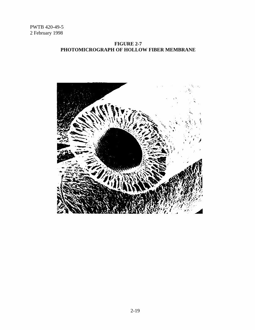
PWTB 420-49-52 February 1998
2-19
FIGURE 2-7PHOTOMICROGRAPH OF HOLLOW FIBER MEMBRANE
PWTB 420-49-52 February 1998
3-1
Chapter 3
Steam Boiler Systems
Section IGeneral Information
3-1. Boiler system defined. A boiler is anenclosed vessel with an external heat sourcethat produces steam or hot water. Steamboilers are discussed in this chapter (hot waterboilers are addressed in chapter 5). Two typesof boilers are commonly used on Armyinstallations. There are the fire tube boilers,where the hot combustion gas passes throughtubes with the water surrounding the tubes.This type of boiler is common for packageboilers. There also are water tube boilers,where the water is converted to steam withinthe tubes and the hot combustion gases passon the outside. Most Army installations willhave a central boiler plant containing severalsteam and hot water boilers in addition toboilers located in and serving individualbuildings. Central boiler plants should beequipped with external treatment systems toreduce the sludge and scale potential of theboiler water, and with deaerators capable ofdelivering feedwater with low oxygen contentat all operating loads. Where externaltreatment is not available, special precautionsmust be taken to blowdown the boilersufficiently to keep suspended solids at a lowlevel, prevent sludge from forming on boilersurfaces and keep silica concentrations lowenough to prevent deposits.
a. Boiler classification. For the purposeof water treatment, the categories of highpressure (above 15 psig) and low pressure (15psig and below) are sufficient. Boiler capacityrating is given as horsepower, pounds of steamper hour, or British Thermal Units (BTU) per
hour. One boiler horsepower reflects theenergy to convert 34.5 pounds of water tosteam from (and at) 212oF at sea level, whichis equivalent to 33,479 BTU per hour. Theactual steam produced, however, will varydepending on the boiler operating pressure andaltitude with respect to sea level.
b. Treatment program for highpressure steam boilers. Water for high-pressure steam boilers is generally treated forscale control, sludge conditioning, corrosion(oxygen and carbon dioxide), and foaming(steam drum).
c. Treatment program for low pressuresteam boilers. Low pressure boilers areusually installed for single unit heating or toprovide process steam for industrial purposes.The installations are comparatively simple andmay require very little makeup due to smallsteam and condensate losses. These boilersmay need only corrosion control. However, ifsignificant makeup is required these systemswill need a complete water treatment program.
3-2. Components of a steam boiler. Thedesign of a steam boiler is based on a varietyof engineering and service factors. The typicalcomponents that may be included at a specificunit are illustrated in figure 3-1 and brieflydescribed below.
a. External water treatment. Makeupwater for a boiler represents the added amountfrom a completely external source. Thetreatment of makeup water is discussed inchapter 2. A storage tank may be provided forthe treated makeup as part of the boilersystem. The makeup is combined with thecondensed steam returned from the
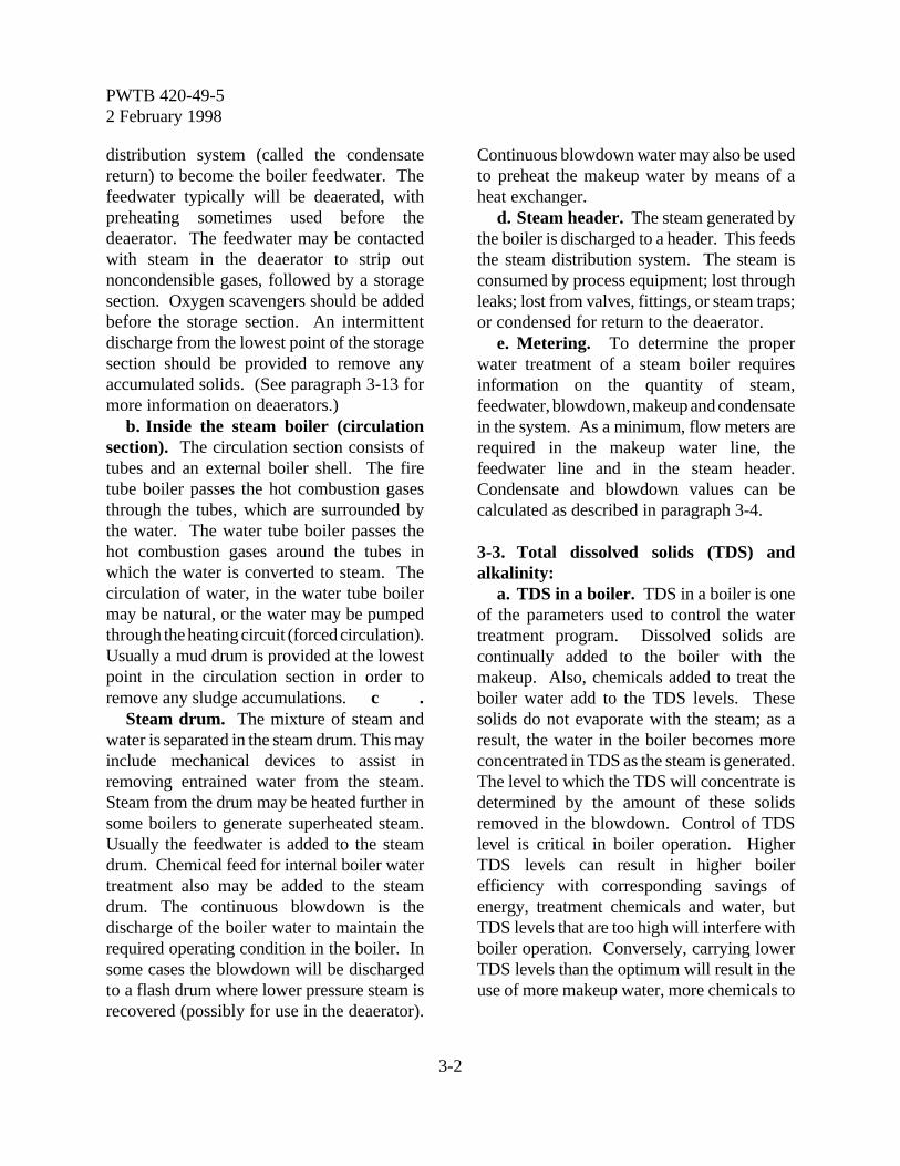
PWTB 420-49-52 February 1998
3-2
distribution system (called the condensatereturn) to become the boiler feedwater. Thefeedwater typically will be deaerated, withpreheating sometimes used before thedeaerator. The feedwater may be contactedwith steam in the deaerator to strip outnoncondensible gases, followed by a storagesection. Oxygen scavengers should be addedbefore the storage section. An intermittentdischarge from the lowest point of the storagesection should be provided to remove anyaccumulated solids. (See paragraph 3-13 formore information on deaerators.)
b. Inside the steam boiler (circulationsection). The circulation section consists oftubes and an external boiler shell. The firetube boiler passes the hot combustion gasesthrough the tubes, which are surrounded bythe water. The water tube boiler passes thehot combustion gases around the tubes inwhich the water is converted to steam. Thecirculation of water, in the water tube boilermay be natural, or the water may be pumpedthrough the heating circuit (forced circulation).Usually a mud drum is provided at the lowestpoint in the circulation section in order toremove any sludge accumulations. c .
Steam drum. The mixture of steam andwater is separated in the steam drum. This mayinclude mechanical devices to assist inremoving entrained water from the steam.Steam from the drum may be heated further insome boilers to generate superheated steam.Usually the feedwater is added to the steamdrum. Chemical feed for internal boiler watertreatment also may be added to the steamdrum. The continuous blowdown is thedischarge of the boiler water to maintain therequired operating condition in the boiler. Insome cases the blowdown will be dischargedto a flash drum where lower pressure steam isrecovered (possibly for use in the deaerator).
Continuous blowdown water may also be usedto preheat the makeup water by means of aheat exchanger.
d. Steam header. The steam generated bythe boiler is discharged to a header. This feedsthe steam distribution system. The steam isconsumed by process equipment; lost throughleaks; lost from valves, fittings, or steam traps;or condensed for return to the deaerator.
e. Metering. To determine the properwater treatment of a steam boiler requiresinformation on the quantity of steam,feedwater, blowdown, makeup and condensatein the system. As a minimum, flow meters arerequired in the makeup water line, thefeedwater line and in the steam header.Condensate and blowdown values can becalculated as described in paragraph 3-4.
3-3. Total dissolved solids (TDS) andalkalinity:
a. TDS in a boiler. TDS in a boiler is oneof the parameters used to control the watertreatment program. Dissolved solids arecontinually added to the boiler with themakeup. Also, chemicals added to treat theboiler water add to the TDS levels. Thesesolids do not evaporate with the steam; as aresult, the water in the boiler becomes moreconcentrated in TDS as the steam is generated.The level to which the TDS will concentrate isdetermined by the amount of these solidsremoved in the blowdown. Control of TDSlevel is critical in boiler operation. HigherTDS levels can result in higher boilerefficiency with corresponding savings ofenergy, treatment chemicals and water, butTDS levels that are too high will interfere withboiler operation. Conversely, carrying lowerTDS levels than the optimum will result in theuse of more makeup water, more chemicals to
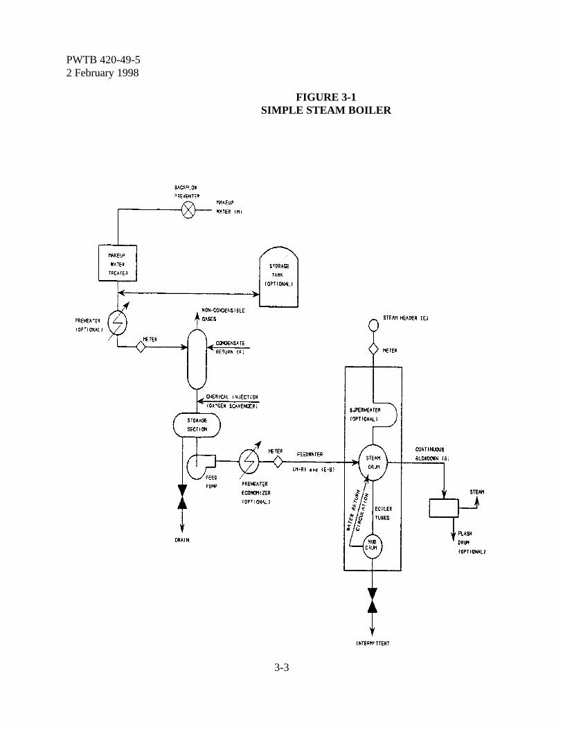
PWTB 420-49-52 February 1998
3-3
FIGURE 3-1SIMPLE STEAM BOILER

PWTB 420-49-52 February 1998
3-4
treat the additional water, and loss of energyrequired to heat the additional water. Incertain cases the TDS may be limited by thewater quality, such as makeup water with highsilica content. Total dissolved solids may becontrolled by the continuous blowdown, whichtypically is removed from the steam drum, orby manual blowdown. Guidelines formaximum TDS levels in boilers operating atvarious steam pressures are shown in table 3-1. It is advisable to keep the TDS in theboiler water just below the maximum allowedin order to save fuel, water and treatmentchemicals. Because of the time it takes todetermine the TDS by evaporation, the TDS iscalculated from the water's conductivity. Therelationship between TDS and conductivityvaries depending on the water quality. Forboilers that use synthetic polymers as a sludgedispersant, a factor of 0.7 times the neutralizedconductivity (in µmhos) may be used. Forboilers that use Quebracho tannin, the factorwill vary from 0.7 to 1.0 depending on theamount of tannin in the water.
b. Alkalinity in a boiler. Alkalinity inboiler water essentially results from thepresence of hydroxyl and carbonate ions. Therelationship of the various forms of alkalinityis covered in paragraph 6-14.
(1) Hydroxyl alkalinity (causticity) inboiler water is necessary to protect the boileragainst corrosion. Proper dosage of sodiumhydroxide is covered in paragraph 3-19. Toohigh a causticity causes other operatingproblems, such as foaming. Excessively highcausticity levels can result in a type of causticattack of the boiler called "embrittlement".
(2) With the phosphate controlprogram phosphate in the boiler watercombines with calcium to precipitate calciumphosphate, removing calcium from the boilerwater. Calcium phosphate, under proper
conditions, forms a finely divided, fluid sludge,which can be carried by the boiler circulationand can, in general, be readily removed byblowdown. Because calcium phosphate is theleast soluble of the calcium salts in boilerwater, phosphate control prevents formationof other calcium scales, such as calciumcarbonate, calcium sulfate, or calcium silicate.The pH in the boiler must be kept above 11.0to prevent possible formation of a stickysludge that adheres to the boiler surfaces.
(3) Causticity in boiler water is theresult of the addition of sodium hydroxide(NaOH) or the breakdown of bicarbonatealkalinity in the feedwater under the influenceof heat to produce sodium carbonate, carbondioxide and water:
2NaHCO3 v NaCO3 + CO2 + H2O
Sodium Sodium Carbon WaterBicarbonate Carbonate Dioxide
Carbonates react with the hot boiler water,although not as fast or as complete as thebicarbonate reaction, to form carbon dioxideand sodium hydroxide which increases thecausticity in the boiler and the acidity of thesteam.
Na2CO3 + H2O v 2NaOH + CO2
Sodium Water Sodium CarbonCarbonate Hydroxide Dioxide
3-4. Boiler blowdown calculations. TDS inthe boiler is controlled by the rate ofblowdown from a boiler.
a. The water added to the boiler must equalwater loss from the boiler.
F = E + Bwhere: F = feedwater, pounds / hour (lb/hr)
E = steam generated, lb/hrB = blowdown, lb/hr
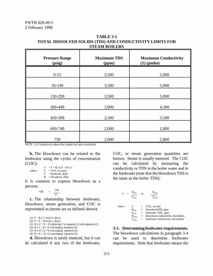
PWTB 420-49-52 February 1998
3-5
TABLE 3-1TOTAL DISSOLVED SOLIDS (TDS) AND CONDUCTIVITY LIMITS FOR
STEAM BOILERS
Pressure Range(psig)
Maximum TDS(ppm)
Maximum Conductivity(1) (µmho)
0-15 3,500 5,000
16-149 3,500 5,000
150-299 3,500 5,000
300-449 3,000 4,300
450-599 2,500 3,500
600-749 2,000 2,800
750 2,000 2,800NOTE: (1) Conductivity taken after sample has been neutralized.
b. The blowdown can be related to thefeedwater using the cycles of concentration(COC):
C = F ÷ B, or F = B x Cwhere: C = COC, no units
F = feedwater, lb/hrB = blowdown, lb/hr
It is common to express blowdown as apercent:
100%B =
C
c. The relationship between feedwater,blowdown, steam generation, and COC isrepresented as (terms are as defined above):
(1) F = B x C from b. above(2) F = E + B from a. above(3) B x C = E + B replacing F in equation 2) with equation (1)(4) B x C - B = E rearranging equation (3)(5) B x (C-1) = E rearranging equation (4)(6) B = E ÷ (C-1) rearranging equation (5)
d. Blowdown is rarely metered, but it canbe calculated if any two of the feedwater,
COC, or steam generation quantities areknown. Steam is usually metered. The COCcan be calculated by measuring theconductivity or TDS in the boiler water and inthe feedwater (note that the blowdown TDS isthe same as the boiler TDS):
BTDS BµmhoC = or FTDS Fµmho
where: C = COC, no unitBTDS = blowdownTDS, ppmFTDS = feedwater TDS, ppmBµmho = blowdown conductivity, micromhosFµmho = feedwater conductivity, micromhos
3-5. Determining feedwater requirements.The blowdown calculations in paragraph 3-4can be used to determine feedwaterrequirements. Note that feedwater means the
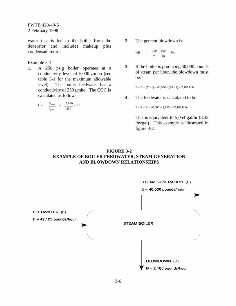
PWTB 420-49-52 February 1998
3-6
FIGURE 3-2EXAMPLE OF BOILER FEEDWATER, STEAM GENERATION
AND BLOWDOWN RELATIONSHIPS
water that is fed to the boiler from thedeaerator and includes makeup pluscondensate return.
Example 3-1:1. A 250 psig boiler operates at a
conductivity level of 5,000 Fmho (seetable 3-1 for the maximum allowablelevel). The boiler feedwater has aconductivity of 250 µmho. The COC iscalculated as follows:
Bµmho 5,000C = or = 20
Fµmho 250
2. The percent blowdown is:
100 100%B = = = 5%
C 20
3. If the boiler is producing 40,000 poundsof steam per hour, the blowdown mustbe:
B = E ÷ (C - 1) = 40,000 ÷ (20 - 1) = 2,105 lb/hr
4. The feedwater is calculated to be:
F = E + B = 40,000 + 2,105 = 42,105 lb/hr
This is equivalent to 5,054 gal/hr (8.33lbs/gal). This example is illustrated infigure 3-2.
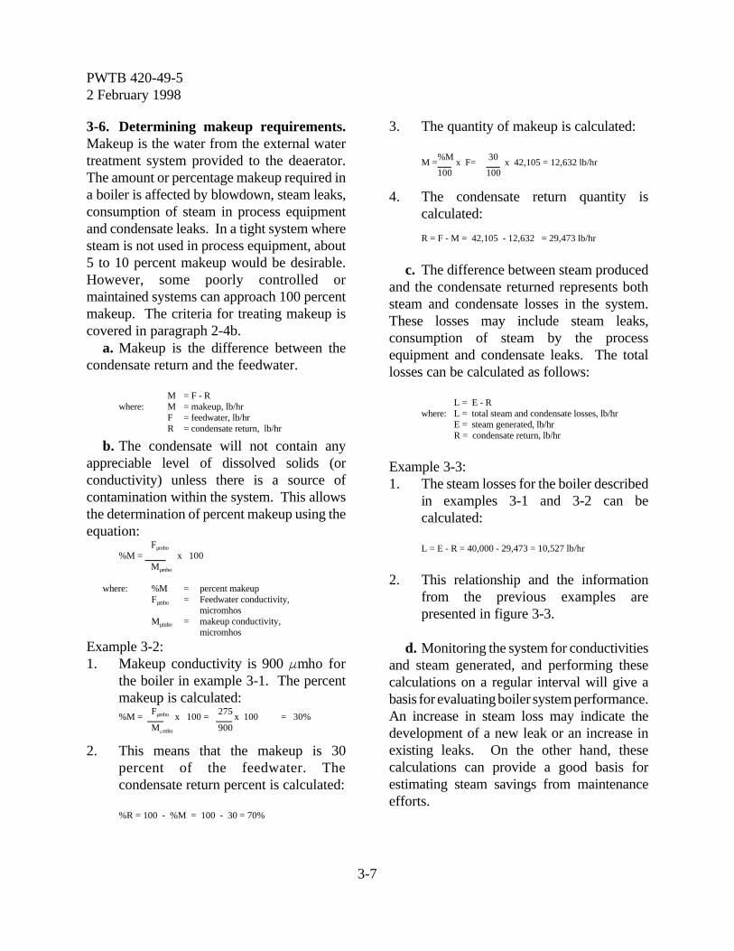
PWTB 420-49-52 February 1998
3-7
3-6. Determining makeup requirements.Makeup is the water from the external watertreatment system provided to the deaerator.The amount or percentage makeup required ina boiler is affected by blowdown, steam leaks,consumption of steam in process equipmentand condensate leaks. In a tight system wheresteam is not used in process equipment, about5 to 10 percent makeup would be desirable.However, some poorly controlled ormaintained systems can approach 100 percentmakeup. The criteria for treating makeup iscovered in paragraph 2-4b.
a. Makeup is the difference between thecondensate return and the feedwater.
M = F - Rwhere: M = makeup, lb/hr
F = feedwater, lb/hr R = condensate return, lb/hr
b. The condensate will not contain anyappreciable level of dissolved solids (orconductivity) unless there is a source ofcontamination within the system. This allowsthe determination of percent makeup using theequation:
Fµmho
%M = x 100 Mµmho
where: %M = percent makeupFµmho = Feedwater conductivity,
micromhosMµmho = makeup conductivity,
micromhos
Example 3-2:1. Makeup conductivity is 900 Fmho for
the boiler in example 3-1. The percentmakeup is calculated:
Fµmho 275%M = x 100 = x 100 = 30%
MFmho 900
2. This means that the makeup is 30percent of the feedwater. Thecondensate return percent is calculated:
%R = 100 - %M = 100 - 30 = 70%
3. The quantity of makeup is calculated:
%M 30M = x F= x 42,105 = 12,632 lb/hr
100 100
4. The condensate return quantity iscalculated:
R = F - M = 42,105 - 12,632 = 29,473 lb/hr
c. The difference between steam producedand the condensate returned represents bothsteam and condensate losses in the system.These losses may include steam leaks,consumption of steam by the processequipment and condensate leaks. The totallosses can be calculated as follows:
L = E - Rwhere: L = total steam and condensate losses, lb/hr
E = steam generated, lb/hrR = condensate return, lb/hr
Example 3-3:1. The steam losses for the boiler described
in examples 3-1 and 3-2 can becalculated:
L = E - R = 40,000 - 29,473 = 10,527 lb/hr
2. This relationship and the informationfrom the previous examples arepresented in figure 3-3.
d. Monitoring the system for conductivitiesand steam generated, and performing thesecalculations on a regular interval will give abasis for evaluating boiler system performance.An increase in steam loss may indicate thedevelopment of a new leak or an increase inexisting leaks. On the other hand, thesecalculations can provide a good basis forestimating steam savings from maintenanceefforts.
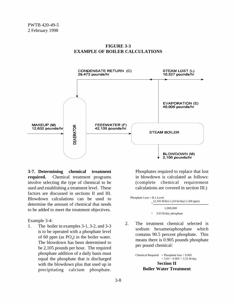
PWTB 420-49-52 February 1998
3-8
FIGURE 3-3 EXAMPLE OF BOILER CALCULATIONS
3-7. Determining chemical treatmentrequired. Chemical treatment programsinvolve selecting the type of chemical to beused and establishing a treatment level. Thesefactors are discussed in sections II and III.Blowdown calculations can be used todetermine the amount of chemical that needsto be added to meet the treatment objectives.
Example 3-4:1. The boiler in examples 3-1, 3-2, and 3-3
is to be operated with a phosphate levelof 60 ppm (as PO4) in the boiler water.The blowdown has been determined tobe 2,105 pounds per hour. The requiredphosphate addition of a daily basis mustequal the phosphate that is dischargedwith the blowdown plus that used up inprecipitating calcium phosphate.
Phosphates required to replace that lostin blowdown is calculated as follows:(complete chemical requirementcalculations are covered in section III.)
Phosphate Loss = B x Level (2,105 lb/hr) x (24 hr/day) x (60 ppm)=
1,000,000
= 3.03 lb/day phosphate
2. The treatment chemical selected issodium hexametaphosphate whichcontains 90.5 percent phosphate. Thismeans there is 0.905 pounds phosphateper pound chemical:
Chemical Required = Phosphate loss ÷ 0.095= 3.03 ÷ 0.905 = 3.35 lb/day
Section IIBoiler Water Treatment
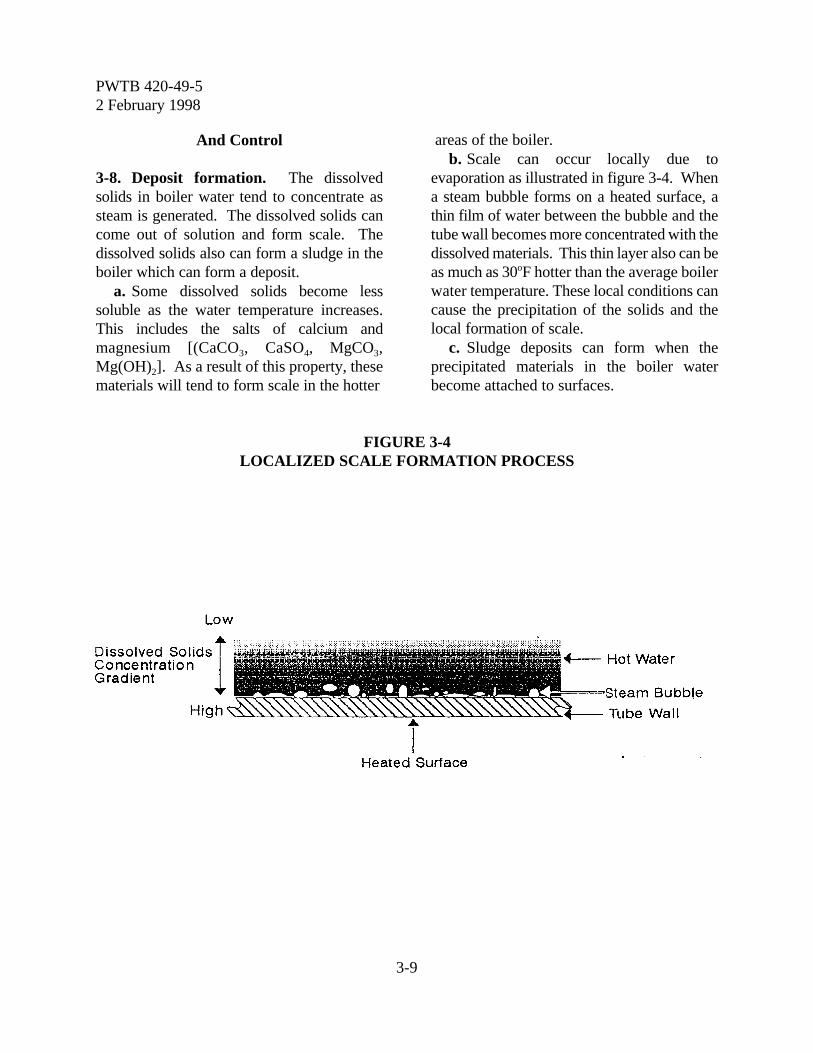
PWTB 420-49-52 February 1998
3-9
And Control
3-8. Deposit formation. The dissolvedsolids in boiler water tend to concentrate assteam is generated. The dissolved solids cancome out of solution and form scale. Thedissolved solids also can form a sludge in theboiler which can form a deposit.
a. Some dissolved solids become lesssoluble as the water temperature increases.This includes the salts of calcium andmagnesium [(CaCO3, CaSO4, MgCO3,Mg(OH)2]. As a result of this property, thesematerials will tend to form scale in the hotter
areas of the boiler.b. Scale can occur locally due to
evaporation as illustrated in figure 3-4. Whena steam bubble forms on a heated surface, athin film of water between the bubble and thetube wall becomes more concentrated with thedissolved materials. This thin layer also can beas much as 30oF hotter than the average boilerwater temperature. These local conditions cancause the precipitation of the solids and thelocal formation of scale.
c. Sludge deposits can form when theprecipitated materials in the boiler waterbecome attached to surfaces.
FIGURE 3-4LOCALIZED SCALE FORMATION PROCESS
PWTB 420-49-52 February 1998
3-10
3-9. Problems caused by scaling. Normallythe steam boiler uses an external heat sourcemuch hotter than the boiler water. The metaltubes in the boiler are kept cool by the boilerwater. When scale forms, it acts like aninsulating material between the water and themetal. This results in the metal tubesoperating at a higher temperature. The greaterthe thickness of scale, the greater theinsulating effect and the higher the temperatureof the tubes. At sufficiently high temperatures,the tube can lose tensile strength and rupture.The insulating property of a scale can act inany part of the boiler system to reduce the heattransfer capacity of affected areas.
3-10. Common scales found in boilers.The most common scales consist of calciumand magnesium salts and iron oxide.
a. Calcium carbonate. Calcium carbonateis caused by the breakdown of calciumbicarbonate by heat. It is found in untreatedboilers, or improperly treated boilers.
b. Calcium sulfate. Calcium sulfate(gypsum) is found in boilers using highhardness, low alkalinity water, without propertreatment.
c. Calcium phosphate. Calciumphosphate is formed when the calcium in thefeedwater reacts with the phosphate used fortreatment. With proper treatment, this willform a sludge which can be removed in theblowdown. However, calcium phosphate candeposit as scale if the pH of the boiler water isbelow 11.0 and a sludge condition is not used.
d. Magnesium phosphate. Magnesiumphosphate is caused by the reaction ofmagnesium salts in the feedwater with thephosphate used in the treatment. It will formonly if the hydroxide content and the silicacontent of the boiler water are low.
e. Magnesium silicate. Magnesiumsilicate is formed from the magnesium andsilica in the feedwater if the pH is above 11.0and the silica level is more than half thephosphate level. Normally, it forms as asludge that can be removed in the blowdown,but it may deposit on tubes as scale if a sludgeconditioner is not present.
f. Iron oxide. Iron oxide is formed fromthe dissolved iron in the feedwater andhydroxide in the boiler water. Usually, thedissolved iron comes from the condensatereturn. This also should occur as a sludgewhich can be removed in the blowdown, butiron oxide can deposit as a scale on the boilertubes if a sludge conditioner is not present.
3-11. Internal treatment of boiler water.Internal treatment of boiler water refers to theaddition of chemicals to prevent scaleformation and to prevent sludge deposits fromforming due to precipitation of these materials.
a. Prevention of scale formation. Thebest method is to remove hardness from themakeup in a water softener. Hardness thatenters the boiler has to be treated withchemicals which react with the hardness toform a sludge rather than scale.
(1) Low Pressure Boilers: (15 psig andless) In low pressure systems with no makeupor blowdown, sodium hydroxide (caustic) isadded to maintain a pH between 10.5 and 11.5to help prevent corrosion. Total alkalinity (M-alkalinity) levels greater than 50 ppm (asCaCO3) in the feedwater will normally providesufficient causticity in the boiler without theneed to add sodium hydroxide. If there arehigh makeup requirements, treat the same asfor high pressure boilers. (2) H i g hPressure Boilers: (greater than 15 psig)Phosphate, properly added, will react withboth calcium and magnesium to form a sludge.
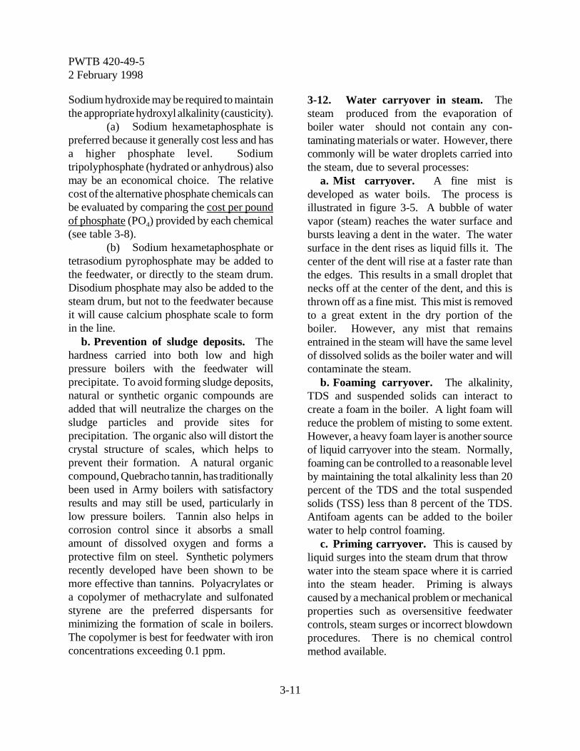
PWTB 420-49-52 February 1998
3-11
Sodium hydroxide may be required to maintainthe appropriate hydroxyl alkalinity (causticity).
(a) Sodium hexametaphosphate ispreferred because it generally cost less and hasa higher phosphate level. Sodiumtripolyphosphate (hydrated or anhydrous) alsomay be an economical choice. The relativecost of the alternative phosphate chemicals canbe evaluated by comparing the cost per poundof phosphate (PO4) provided by each chemical(see table 3-8).
(b) Sodium hexametaphosphate ortetrasodium pyrophosphate may be added tothe feedwater, or directly to the steam drum.Disodium phosphate may also be added to thesteam drum, but not to the feedwater becauseit will cause calcium phosphate scale to formin the line.
b. Prevention of sludge deposits. Thehardness carried into both low and highpressure boilers with the feedwater willprecipitate. To avoid forming sludge deposits,natural or synthetic organic compounds areadded that will neutralize the charges on thesludge particles and provide sites forprecipitation. The organic also will distort thecrystal structure of scales, which helps toprevent their formation. A natural organiccompound, Quebracho tannin, has traditionallybeen used in Army boilers with satisfactoryresults and may still be used, particularly inlow pressure boilers. Tannin also helps incorrosion control since it absorbs a smallamount of dissolved oxygen and forms aprotective film on steel. Synthetic polymersrecently developed have been shown to bemore effective than tannins. Polyacrylates ora copolymer of methacrylate and sulfonatedstyrene are the preferred dispersants forminimizing the formation of scale in boilers.The copolymer is best for feedwater with ironconcentrations exceeding 0.1 ppm.
3-12. Water carryover in steam. Thesteam produced from the evaporation ofboiler water should not contain any con-taminating materials or water. However, therecommonly will be water droplets carried intothe steam, due to several processes:
a. Mist carryover. A fine mist isdeveloped as water boils. The process isillustrated in figure 3-5. A bubble of watervapor (steam) reaches the water surface andbursts leaving a dent in the water. The watersurface in the dent rises as liquid fills it. Thecenter of the dent will rise at a faster rate thanthe edges. This results in a small droplet thatnecks off at the center of the dent, and this isthrown off as a fine mist. This mist is removedto a great extent in the dry portion of theboiler. However, any mist that remainsentrained in the steam will have the same levelof dissolved solids as the boiler water and willcontaminate the steam.
b. Foaming carryover. The alkalinity,TDS and suspended solids can interact tocreate a foam in the boiler. A light foam willreduce the problem of misting to some extent.However, a heavy foam layer is another sourceof liquid carryover into the steam. Normally,foaming can be controlled to a reasonable levelby maintaining the total alkalinity less than 20percent of the TDS and the total suspendedsolids (TSS) less than 8 percent of the TDS.Antifoam agents can be added to the boilerwater to help control foaming.
c. Priming carryover. This is caused byliquid surges into the steam drum that throw water into the steam space where it is carriedinto the steam header. Priming is alwayscaused by a mechanical problem or mechanicalproperties such as oversensitive feedwatercontrols, steam surges or incorrect blowdownprocedures. There is no chemical controlmethod available.
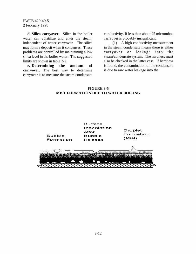
PWTB 420-49-52 February 1998
3-12
d. Silica carryover. Silica in the boilerwater can volatilize and enter the steam,independent of water carryover. The silicamay form a deposit when it condenses. Theseproblems are controlled by maintaining a lowsilica level in the boiler water. The suggestedlimits are shown in table 3-2.
e. Determining the amount ofcarryover. The best way to determinecarryover is to measure the steam condensate
conductivity. If less than about 25 micromhoscarryover is probably insignificant.
(1) A high conductivity measurementin the steam condensate means there is eitherca r ryover o r l eakage in to thesteam/condensate system. The hardness mustalso be checked in the latter case. If hardnessis found, the contamination of the condensateis due to raw water leakage into the
FIGURE 3-5MIST FORMATION DUE TO WATER BOILING
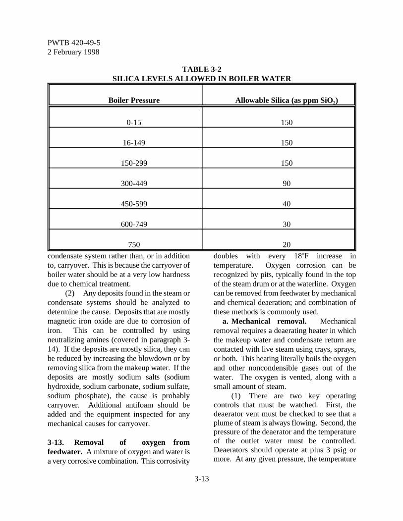
PWTB 420-49-52 February 1998
3-13
TABLE 3-2SILICA LEVELS ALLOWED IN BOILER WATER
Boiler Pressure Allowable Silica (as ppm SiO2)
0-15 150
16-149 150
150-299 150
300-449 90
450-599 40
600-749 30
750 20
condensate system rather than, or in additionto, carryover. This is because the carryover ofboiler water should be at a very low hardnessdue to chemical treatment.
(2) Any deposits found in the steam orcondensate systems should be analyzed todetermine the cause. Deposits that are mostlymagnetic iron oxide are due to corrosion ofiron. This can be controlled by usingneutralizing amines (covered in paragraph 3-14). If the deposits are mostly silica, they canbe reduced by increasing the blowdown or byremoving silica from the makeup water. If thedeposits are mostly sodium salts (sodiumhydroxide, sodium carbonate, sodium sulfate,sodium phosphate), the cause is probablycarryover. Additional antifoam should beadded and the equipment inspected for anymechanical causes for carryover.
3-13. Removal of oxygen fromfeedwater. A mixture of oxygen and water isa very corrosive combination. This corrosivity
doubles with every 18oF increase intemperature. Oxygen corrosion can berecognized by pits, typically found in the topof the steam drum or at the waterline. Oxygencan be removed from feedwater by mechanicaland chemical deaeration; and combination ofthese methods is commonly used.
a. Mechanical removal. Mechanicalremoval requires a deaerating heater in whichthe makeup water and condensate return arecontacted with live steam using trays, sprays,or both. This heating literally boils the oxygenand other noncondensible gases out of thewater. The oxygen is vented, along with asmall amount of steam.
(1) There are two key operatingcontrols that must be watched. First, thedeaerator vent must be checked to see that aplume of steam is always flowing. Second, thepressure of the deaerator and the temperatureof the outlet water must be controlled.Deaerators should operate at plus 3 psig ormore. At any given pressure, the temperature
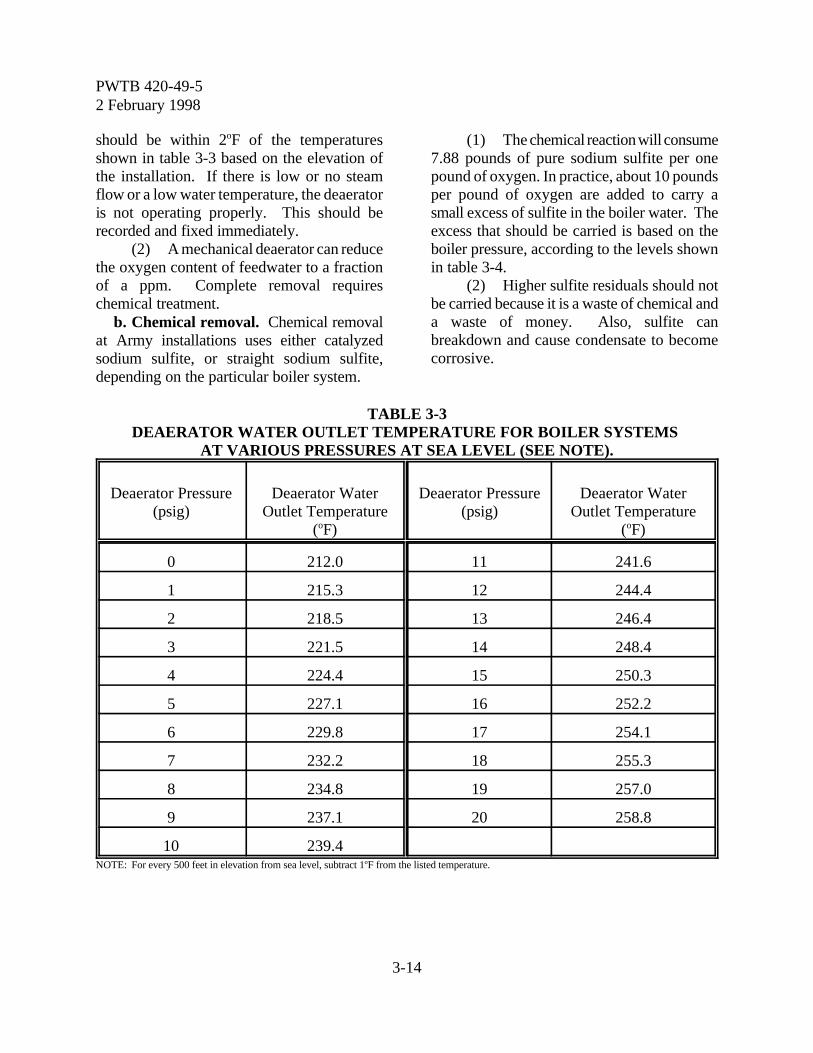
PWTB 420-49-52 February 1998
3-14
should be within 2oF of the temperaturesshown in table 3-3 based on the elevation ofthe installation. If there is low or no steamflow or a low water temperature, the deaeratoris not operating properly. This should berecorded and fixed immediately.
(2) A mechanical deaerator can reducethe oxygen content of feedwater to a fractionof a ppm. Complete removal requireschemical treatment.
b. Chemical removal. Chemical removalat Army installations uses either catalyzedsodium sulfite, or straight sodium sulfite,depending on the particular boiler system.
(1) The chemical reaction will consume7.88 pounds of pure sodium sulfite per onepound of oxygen. In practice, about 10 poundsper pound of oxygen are added to carry asmall excess of sulfite in the boiler water. Theexcess that should be carried is based on theboiler pressure, according to the levels shownin table 3-4.
(2) Higher sulfite residuals should notbe carried because it is a waste of chemical anda waste of money. Also, sulfite canbreakdown and cause condensate to becomecorrosive.
TABLE 3-3DEAERATOR WATER OUTLET TEMPERATURE FOR BOILER SYSTEMS
AT VARIOUS PRESSURES AT SEA LEVEL (SEE NOTE).
Deaerator Pressure(psig)
Deaerator WaterOutlet Temperature
(oF)
Deaerator Pressure(psig)
Deaerator WaterOutlet Temperature
(oF)
0 212.0 11 241.6
1 215.3 12 244.4
2 218.5 13 246.4
3 221.5 14 248.4
4 224.4 15 250.3
5 227.1 16 252.2
6 229.8 17 254.1
7 232.2 18 255.3
8 234.8 19 257.0
9 237.1 20 258.8
10 239.4NOTE: For every 500 feet in elevation from sea level, subtract 1oF from the listed temperature.
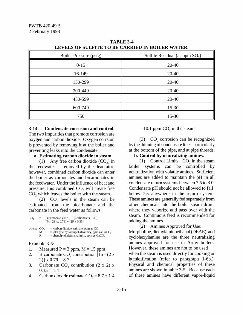
PWTB 420-49-52 February 1998
3-15
TABLE 3-4LEVELS OF SULFITE TO BE CARRIED IN BOILER WATER.
Boiler Pressure (psig) Sulfite Residual (as ppm SO3)
0-15 20-40
16-149 20-40
150-299 20-40
300-449 20-40
450-599 20-40
600-749 15-30
750 15-30
3-14. Condensate corrosion and control.The two impurities that promote corrosion areoxygen and carbon dioxide. Oxygen corrsionis prevented by removing it at the boiler andpreventing leaks into the condensate.
a. Estimating carbon dioxide in steam.(1) Any free carbon dioxide (CO2) in
the feedwater is removed by the deaerator,however, combined carbon dioxide can enterthe boiler as carbonates and bicarbonates inthe feedwater. Under the influence of heat andpressure, this combined CO2 will create freeCO2 which leaves the boiler with the steam.
(2) CO2 levels in the steam can beestimated from the bicarbonate and thecarbonate in the feed water as follows:
CO2 = [Bicarbonate x 0.79] + [Carbonate x 0.35]= [(M - 2P) x 0.79] + [2P x 0.35]
where: CO2 = carbon dioxide estimate, ppm as CO2
M = total (methyl orange) alkalinity, ppm as CaCO3
P = phenolphthalein alkalinity, ppm as CaCO3
Example 3-5:1. Measured P = 2 ppm, M = 15 ppm2. Bicarbonate CO2 contribution [15 - (2 x
2)] x 0.79 = 8.73. Carbonate CO2 contribution (2 x 2) x
0.35 = 1.44. Carbon dioxide estimate CO2 = 8.7 + 1.4
= 10.1 ppm CO2 in the steam
(3) CO2 corrosion can be recognizedby the thinning of condensate lines, particularlyat the bottom of the pipe, and at pipe threads.
b. Control by neutralizing amines.(1) Control Limits: CO2 in the steam
boiler systems can be controlled byneutralization with volatile amines. Sufficientamines are added to maintain the pH in allcondensate return systems between 7.5 to 8.0.Condensate pH should not be allowed to fallbelow 7.5 anywhere in the return system.These amines are generally fed separately fromother chemicals into the boiler steam drum,where they vaporize and pass over with thesteam. Continuous feed is recommended foradding the amines.
(2) Amines Approved for Use: Morpholine, diethylaminoethanol (DEAE), andcyclohexylamine are the three neutralizingamines approved for use in Army boilers.However, these amines are not to be usedwhen the steam is used directly for cooking orhumidification (refer to paragraph 1-6b.).Physical and chemical properties of theseamines are shown in table 3-5. Because eachof these amines have different vapor-liquid
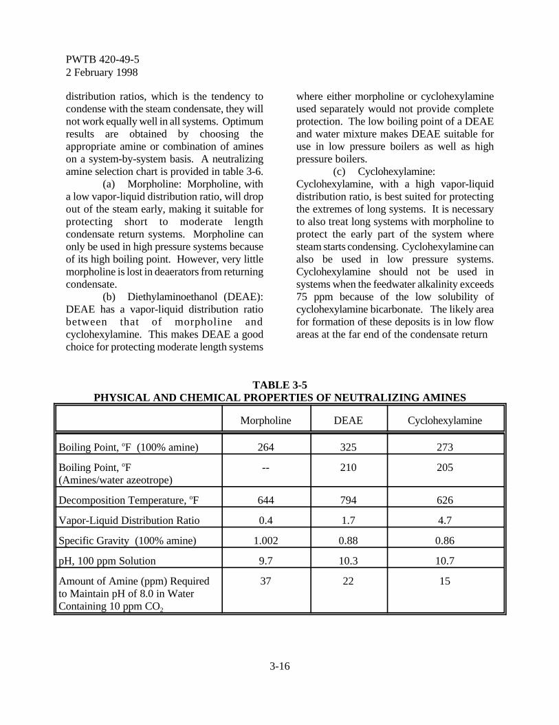
PWTB 420-49-52 February 1998
3-16
distribution ratios, which is the tendency tocondense with the steam condensate, they willnot work equally well in all systems. Optimumresults are obtained by choosing theappropriate amine or combination of amineson a system-by-system basis. A neutralizingamine selection chart is provided in table 3-6.
(a) Morpholine: Morpholine, witha low vapor-liquid distribution ratio, will dropout of the steam early, making it suitable forprotecting short to moderate lengthcondensate return systems. Morpholine canonly be used in high pressure systems becauseof its high boiling point. However, very littlemorpholine is lost in deaerators from returningcondensate.
(b) Diethylaminoethanol (DEAE):DEAE has a vapor-liquid distribution ratiobetween that of morpholine andcyclohexylamine. This makes DEAE a goodchoice for protecting moderate length systems
where either morpholine or cyclohexylamineused separately would not provide completeprotection. The low boiling point of a DEAEand water mixture makes DEAE suitable foruse in low pressure boilers as well as highpressure boilers.
(c) Cyclohexylamine: Cyclohexylamine, with a high vapor-liquiddistribution ratio, is best suited for protectingthe extremes of long systems. It is necessaryto also treat long systems with morpholine toprotect the early part of the system wheresteam starts condensing. Cyclohexylamine canalso be used in low pressure systems.Cyclohexylamine should not be used insystems when the feedwater alkalinity exceeds75 ppm because of the low solubility ofcyclohexylamine bicarbonate. The likely areafor formation of these deposits is in low flowareas at the far end of the condensate return
TABLE 3-5PHYSICAL AND CHEMICAL PROPERTIES OF NEUTRALIZING AMINES
Morpholine DEAE Cyclohexylamine
Boiling Point, oF (100% amine) 264 325 273
Boiling Point, oF(Amines/water azeotrope)
-- 210 205
Decomposition Temperature, oF 644 794 626
Vapor-Liquid Distribution Ratio 0.4 1.7 4.7
Specific Gravity (100% amine) 1.002 0.88 0.86
pH, 100 ppm Solution 9.7 10.3 10.7
Amount of Amine (ppm) Requiredto Maintain pH of 8.0 in WaterContaining 10 ppm CO2
37 22 15
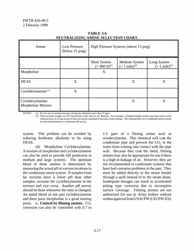
PWTB 420-49-52 February 1998
3-17
TABLE 3-6NEUTRALIZING AMINE SELECTION CHART.
Amine Low Pressure(below 15 psig)
High Pressure Systems (above 15 psig)
Short System(< 800 ft)(2)
Medium System(< 1 mile)(2)
Long System(> 1 mile)(2)
Morpholine X
DEAE X X X
Cyclohexylamine (1) X
Cyclohexylamine/Morpholine Mixture
X X
NOTES: (1) Not for use in systems having a feedwater alkalinity more than 75 ppm.(2) These systems lengths are for classification only and are not absolute. For example, a medium length system may have more of the
characteristics of a long system if lines are poorly insulated or because of poor design. The characteristics of a condensate return systemare best determined by a condensate pH survey.
system. This problem can be avoided byreducing feedwater alkalinity or by usingDEAE.
(d) Morpholine/ Cyclohexylamine:A mixture of morpholine and cyclohexylaminecan also be used to provide full protection inmedium and large systems. The optimumblend of these amines is determined bymeasuring the actual pH at various locations inthe condensate return system. If samples fromfar sections have a lower pH than othersamples, increase the cyclohexylamine in themixture and vice versa. Another pH surveyshould be done whenever the ratio is changed.An initial blend of one part cyclohexylamineand three parts morpholine is a good startingpoint. c. Control by filming amines. CO2
corrosion can also be controlled with 0.7 to
1.0 ppm of a filming amine such asoctadecylamine. This chemical will coat thecondensate pipe and prevent the CO2 in thewater from coming into contact with the pipewall. Because they coat the metal, filmingamines may also be appropriate for use if thereis a high in leakage of air. However, they arenot recommended in condensate systems thathave had corrosion problems in the past. Theymust be added directly to the steam headerthrough a quill instead of to the steam drum.Inadequate dosages can result in acceleratedpitting type corrosion due to incompletesurface coverage. Filming amines are notauthorized for use in Army boilers withoutwritten approval from USACPW (CECPW-ES).
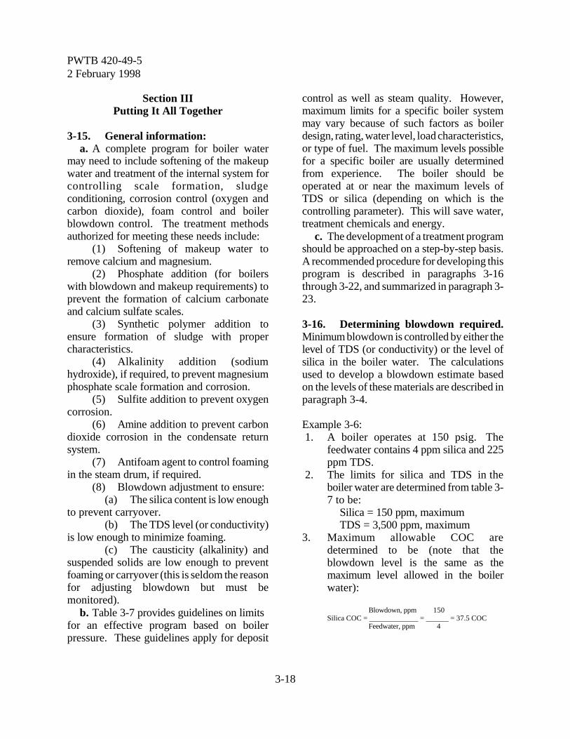
PWTB 420-49-52 February 1998
3-18
Section IIIPutting It All Together
3-15. General information:a. A complete program for boiler water
may need to include softening of the makeupwater and treatment of the internal system forcontrolling scale formation, sludgeconditioning, corrosion control (oxygen andcarbon dioxide), foam control and boilerblowdown control. The treatment methodsauthorized for meeting these needs include:
(1) Softening of makeup water toremove calcium and magnesium.
(2) Phosphate addition (for boilerswith blowdown and makeup requirements) toprevent the formation of calcium carbonateand calcium sulfate scales.
(3) Synthetic polymer addition toensure formation of sludge with propercharacteristics.
(4) Alkalinity addition (sodiumhydroxide), if required, to prevent magnesiumphosphate scale formation and corrosion.
(5) Sulfite addition to prevent oxygencorrosion.
(6) Amine addition to prevent carbondioxide corrosion in the condensate returnsystem.
(7) Antifoam agent to control foamingin the steam drum, if required.
(8) Blowdown adjustment to ensure:(a) The silica content is low enough
to prevent carryover.(b) The TDS level (or conductivity)
is low enough to minimize foaming.(c) The causticity (alkalinity) and
suspended solids are low enough to preventfoaming or carryover (this is seldom the reasonfor adjusting blowdown but must bemonitored).
b. Table 3-7 provides guidelines on limits for an effective program based on boilerpressure. These guidelines apply for deposit
control as well as steam quality. However,maximum limits for a specific boiler systemmay vary because of such factors as boilerdesign, rating, water level, load characteristics,or type of fuel. The maximum levels possiblefor a specific boiler are usually determinedfrom experience. The boiler should beoperated at or near the maximum levels ofTDS or silica (depending on which is thecontrolling parameter). This will save water,treatment chemicals and energy.
c. The development of a treatment programshould be approached on a step-by-step basis.A recommended procedure for developing thisprogram is described in paragraphs 3-16through 3-22, and summarized in paragraph 3-23.
3-16. Determining blowdown required.Minimum blowdown is controlled by either thelevel of TDS (or conductivity) or the level ofsilica in the boiler water. The calculationsused to develop a blowdown estimate basedon the levels of these materials are described inparagraph 3-4.
Example 3-6: 1. A boiler operates at 150 psig. The
feedwater contains 4 ppm silica and 225ppm TDS.
2. The limits for silica and TDS in theboiler water are determined from table 3-7 to be:
Silica = 150 ppm, maximumTDS = 3,500 ppm, maximum
3. Maximum allowable COC aredetermined to be (note that theblowdown level is the same as themaximum level allowed in the boilerwater):
Blowdown, ppm 150Silica COC = _____________ = ______ = 37.5 COC
Feedwater, ppm 4
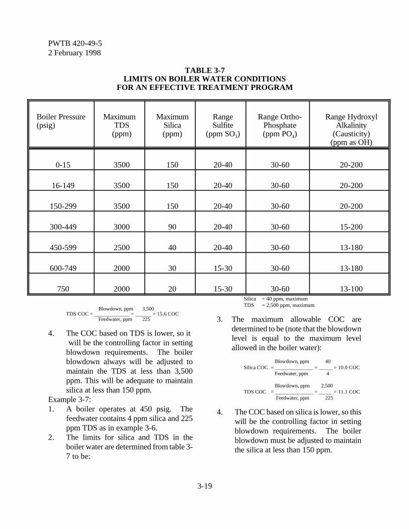
PWTB 420-49-52 February 1998
3-19
TABLE 3-7LIMITS ON BOILER WATER CONDITIONS
FOR AN EFFECTIVE TREATMENT PROGRAM
Boiler Pressure(psig)
MaximumTDS
(ppm)
MaximumSilica(ppm)
RangeSulfite
(ppm SO3)
Range Ortho-Phosphate(ppm PO4)
Range HydroxylAlkalinity
(Causticity)(ppm as OH)
0-15 3500 150 20-40 30-60 20-200
16-149 3500 150 20-40 30-60 20-200
150-299 3500 150 20-40 30-60 20-200
300-449 3000 90 20-40 30-60 15-200
450-599 2500 40 20-40 30-60 13-180
600-749 2000 30 15-30 30-60 13-180
750 2000 20 15-30 30-60 13-100
Blowdown, ppm 3,500TDS COC = _____________ = ______ = 15.6 COC
Feedwater, ppm 225
4. The COC based on TDS is lower, so it will be the controlling factor in settingblowdown requirements. The boilerblowdown always will be adjusted tomaintain the TDS at less than 3,500ppm. This will be adequate to maintainsilica at less than 150 ppm.
Example 3-7:1. A boiler operates at 450 psig. The
feedwater contains 4 ppm silica and 225ppm TDS as in example 3-6.
2. The limits for silica and TDS in theboiler water are determined from table 3-7 to be:
Silica = 40 ppm, maximumTDS = 2,500 ppm, maximum
3. The maximum allowable COC aredetermined to be (note that the blowdownlevel is equal to the maximum levelallowed in the boiler water):
Blowdown, ppm 40Silica COC = ______________ = _____ = 10.0 COC
Feedwater, ppm 4
Blowdown, ppm 2,500 TDS COC = ______________ = _____ = 11.1 COC
Feedwater, ppm 225
4. The COC based on silica is lower, so thiswill be the controlling factor in settingblowdown requirements. The boilerblowdown must be adjusted to maintainthe silica at less than 150 ppm.
PWTB 420-49-52 February 1998
3-20
5. It is easier to measure TDS (orconductivity) than silica in boiler water.Therefore, it will be more convenient tocontrol the TDS to be always lower thanthe TDS level that would occur at 10.0COC. The TDS level at 10 COC can becalculated:
Boiler TDS, max. = feedwater TDS x COC = 225 ppm x 10.0 = 2,250 ppm
6. The same calculation can be performedusing conductivity data. (Note thatwhen measured properly, for boilersusing synthetic polymers, neutralizedconductivity = TDS ÷ 0.7.)
NeutralizedConductivity, max. = TDS, maximum ÷ 0.7
= 2,250 ppm ÷ 0.7 = 3,214 micromhos
Example 3-8:1. The 150 psig boiler in example 3-6
produces 40,000 pounds of steam perhour. The blowdown is calculated basedon the maximum COC of 15.6 as follows(paragraph 3-4c covers the relationshipbetween steam generated andblowdown):
B = E ÷ (C - 1) = 40,000 lb/hr ÷ (15.6 - 1) = 2,740 lb/hr
2. The blowdown in lb/day = 24 x 2,740 =65,760
3. The blowdown in gal/day = 65,760 ÷8.33 = 7,894 (where 8.33 = lb/gal ofwater).
Example 3-9:1. The 450 psig boiler in example 3-7
produces 40,000 pounds of steam perhour. The blowdown required tooperate the boiler is calculated based onthe steam generated (40,000 lb/hr) andthe maximum COC 10.0 using therelationship:B = E ÷ (C -1) = 40,000 lb/hr ÷ (10.0 - 1) = 4,444 lb/hr
2. The blowdown in lb/day = 24 x 4,444 =106,656.
3. The blowdown in gal/day = 106,656 ÷8.33 = 12,804 (where 8.33 = lb/gal ofwater).
3-17. Determining phosphate required toreplace blowdown loss. For systems thatrequire phosphate, the recommended range tocarry in the boiler water is 30 to 60 ppm (asorthophosphate, PO4). The amount ofchemical to add is the sum of phosphate lost inthe blowdown and the phosphate that reactswith the hardness in the feedwater. The typeof phosphate chemical selected for use willdetermine the actual amount of chemical toadd (see paragraph 3-11a which giveinformation on selecting the chemical). Thep r e f e r r e d c h e m i c a l i s s o d i u mhexametaphosphate because of the relativelylow cost and high phosphate level. The use ofsodium tripolyphosphate (hydrated oranhydrous) also may be an economical choicedue to local conditions. The amount ofchemical to add depends upon theconcentration of phosphate in the chemicalthat is used (table 3-8).
Example 3-10:1. The 150 psig boiler in example 3-6 will
require a phosphate chemical, preferablysodium hexametaphosphate. The amountof phosphate required to maintain 60ppm in the boiler water is calculatedbased on the blowdown loss (65,760lb/day, per example 3-8):
Phosphate Loss = 65,760 lb/day x 60 ppm ÷ 1,000,000 = 3.95 lb/day
2. If the chemical selected is sodiumhexametaphosphate, table 3-8 shows the

PWTB 420-49-52 February 1998
3-21
phosphate (PO4) content to be 90.5percent. The required daily feed of thischemical to replace the phosphate lost inthe blowdown is:
phosphate lb/dayFeed, hexametaphosphate = x 100
% phosphate
3.95 = x 100 = 4.36 lb/day
90.5
3. If the chemical selected is anhydrousdisodium phosphate, table 3-8 shows thephosphate to be 65.7 percent. Therequired daily feed is:
Feed, anhydrous phosphate lb/daydisodium phosphate =
% phosphate
3.95= x 100 = 6.01 lb/day
65.7
Example 3-11:1. The 450 psig boiler in example 3-7 will
require a phosphate chemical based onthe discussions in segment 3-11a. Theamount of phosphate required tomaintain 60 ppm in the boiler water iscalculated based on the blowdown loss(106,656 pounds water/day, per example3-9):
Phosphate = 106,656 lb/day x 60 ppm ÷ 1,000,000= 6.40 lb/day
2. If the chemical selected is sodiumhexametaphosphate, table 3-8 shows thephosphate to be 90.5 percent. Therequired daily feed of this chemical toreplace the phosphate lost in theblowdown is:Feed, phosphate lb/dayhexametaphosphate = x 100
% phosphate
6.4= x 100 = 7.07 lb/day
90.5
3. If the chemical selected is anhydrousdisodium phosphate, table 3-8 shows thephosphate to be 65.7 percent. Therequired daily feed is:
Phosphate lb/dayFeed, disodium phosphate = x 100
% phosphate
6.40 x 100 = = 9.74 lb/day
65.7
3-18. Determining phosphate requiredfor hardness reaction. Any calcium ormagnesium hardness in the feedwater willreact with the phosphate added to form aprecipitate. Additional phosphate required toreact with the hardness is presented in table 3-8 as the pounds of phosphate chemicalrequired per 1,000 gallons feedwater per ppmhardness. The total phosphate dose in thefeedwater is the sum of the requirements formaintaining the 30 to 60 ppm level (paragraph3-17) and the hardness reaction. The chemicaldose should be gradually increased ordecreased as necessary (about 10 percent perday) to maintain the desired level.
Example 3-12:1. The 150 psig boiler in example 3-6
produces 40,000 pounds of steam perhour. It was determined in example 3-8that the blowdown is 2,740 pounds perhour. The total feedwater quantity iscalculated:
F = E + B = 40,000 + 2,740 = 42,740 lb/hr= 42,740 x 24 hr/day= 1,025,760 lb/day= 1,025,760 ÷ 8.33 lb/gal= 123,140 gal/day
2. The feedwater contains 5 ppm hardness.The selected phosphate chemical issodium hexametaphosphate. From table3-8, the required addition per 1,000
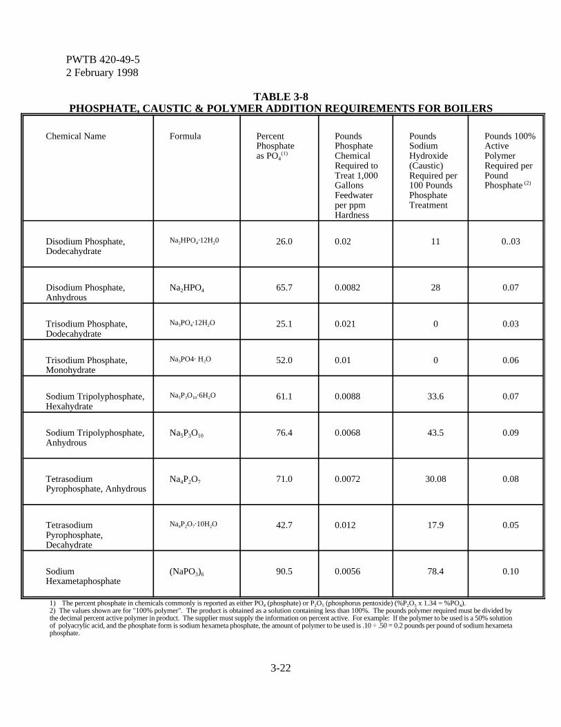
PWTB 420-49-52 February 1998
3-22
TABLE 3-8PHOSPHATE, CAUSTIC & POLYMER ADDITION REQUIREMENTS FOR BOILERS
Chemical Name Formula PercentPhosphateas PO4
(1)
PoundsPhosphateChemicalRequired toTreat 1,000GallonsFeedwaterper ppmHardness
PoundsSodiumHydroxide(Caustic)Required per100 PoundsPhosphateTreatment
Pounds 100%ActivePolymerRequired perPoundPhosphate (2)
Disodium Phosphate,Dodecahydrate
Na2HPO4@12H20 26.0 0.02 11 0..03
Disodium Phosphate,Anhydrous
Na2HPO4 65.7 0.0082 28 0.07
Trisodium Phosphate,Dodecahydrate
Na3PO4@12H2O 25.1 0.021 0 0.03
Trisodium Phosphate,Monohydrate
Na3PO4@ H2O 52.0 0.01 0 0.06
Sodium Tripolyphosphate,Hexahydrate
Na5P3O10@6H2O 61.1 0.0088 33.6 0.07
Sodium Tripolyphosphate,Anhydrous
Na5P3O10 76.4 0.0068 43.5 0.09
TetrasodiumPyrophosphate, Anhydrous
Na4P2O7 71.0 0.0072 30.08 0.08
TetrasodiumPyrophosphate,Decahydrate
Na4P2O7@10H2O 42.7 0.012 17.9 0.05
SodiumHexametaphosphate
(NaPO3)6 90.5 0.0056 78.4 0.10
1) The percent phosphate in chemicals commonly is reported as either PO4 (phosphate) or P2O5 (phosphorus pentoxide) (%P2O5 x 1.34 = %PO4).2) The values shown are for "100% polymer". The product is obtained as a solution containing less than 100%. The pounds polymer required must be divided bythe decimal percent active polymer in product. The supplier must supply the information on percent active. For example: If the polymer to be used is a 50% solutionof polyacrylic acid, and the phosphate form is sodium hexameta phosphate, the amount of polymer to be used is .10 ÷ .50 = 0.2 pounds per pound of sodium hexametaphosphate.

PWTB 420-49-52 February 1998
3-23
gallons feedwater for hardness removal is:
Chemical = 5 ppm H x 0.0056 lbs/1,000 gallons/ppm H= 0.028 lb/thousand gallons
3. Additional chemical for the hardnessreaction is calculated:
12 3,140Chemical per day = 0.028 lb/thousand gal. x = 3.4 lb/day
1,000
4. The chemical added to maintain the 60ppm PO4 level was calculated in example3-10 to be 4.36 lb/day. The total sodiumhexametaphosphate requirement iscalculated:
Sodium hexametaphosphate = 4.36 + 3.45 = 7.81/day
3-19. Determining sodium hydroxide(caustic soda) required. The boiler waterhydroxyl alkalinity (causticity) must bemaintained at the levels in table 3-7 to helpprevent corrosion and the formation ofmagnesium phosphate sludge which willadhere to the surface. The amount of sodiumhydroxide required for each of the phosphatechemicals is shown in table 3-8. Whensoftened water is used as makeup, sufficientalkalinity may be present to provide therequired causticity in the boiler without addingsodium hydroxide.
Example 3-13:1. The 150 psig boiler in example 3-12 will
require 7.81 pounds of sodiumhexametaphosphate per day.
2. Table 3-8 shows that 78.4 poundssodium hydroxide is required per 100pounds of phosphate treatment. Sodiumhydroxide (NaOH) needed is calculated:
78.4 lb NaOHNaOH = 7.81 lb chemical/day x 100 lb chemical
= 6.12 lb sodium hydroxide/day
Example 3-14:1. The 450 psig boiler in example 3-11 will
require 9.74 pounds per day ofanhydrous disodium phosphate toreplace the loss in the blowdown.
2. Table 3-8 shows that 28 pounds sodiumhydroxide is required per 100 pounds ofphosphate chemical. Sodium hydroxide(NaOH) needed is calculated:
28 lb NaOHNaOH = 9.74 lb chemical/day x
100 lb chemical= 2.73 lb/day
3-20. Determining synthetic polymerdosage. There is no easy test methodcurrently available for determining theconcentration of polymers in boiler water. Toensure that there is always an adequate level ofpolymer in the boiler, the polymer is mixed andfed with phosphate in the ratio of 0.1 poundsof polymer per pound of available PO4 in thephosphate used. The amount of activepolymer to add to various types of phosphateto achieve the desired 0.1 ratio is provided inthe last column of table 3-8.
Example 3-15:1. The 150 psig boiler in example 3-12
requires 7.81 lb/day of sodiumhexametaphosphate.
2. Table 3-8 shows that 0.10 pounds ofactive polymer per pound of sodiumhexametaphosphate.
Synthetic polymer = 7.81 x 0.10 = 0.78 lbs/day of 100% polymer
3. Assume the polymer used is only 50%active, then the amount of polymerrequired is:
1000.78 x = 1.56 lb/day
50
3-21. Determining sulfite dosage. Sulfiteat levels shown in table 3-4 is required toremove oxygen from the feedwater. More
PWTB 420-49-52 February 1998
3-24
sulfite is needed to maintain these levels whenthere is no deaerating heater. The initialdosage should be calculated for the middle ofthe range in table 3-4 and then adjusted tomaintain the desired level.
Example 3-16:1. The 150 psig boiler in example 3-8 needs
20 to 40 ppm sulfite (as SO3). Thesulfite dosage is initially selected at themidpoint level of 30 ppm. Theblowdown is 65,760 lb/day asdetermined in example 3-8. The sulfiterequired is calculated based on chemicallost in the blowdown:
Sulfite = 65,760 x 30 ÷ 1,000,000 = 1.97 lb/day
2. There is one pound of sulfite per 1.575pounds sodium sulfite. The amountrequired is calculated:
Sodium sulfite = 1.97 x 1.575 = 3.10 lb/day
Example 3-17:1. The 450 psig boiler in example 3-9 needs
20 to 40 ppm sulfite (as SO3). Themidpoint of 30 ppm is initially selected.The blowdown is 106,656 pounds perday as determined in example 3-9. Therequired sulfite is calculated based onchemical lost in the blowdown:
Sulfite = 106,656 x 30 ÷ 1,000,000 = 3.20 lb/day
2. There is one pound of sulfite per 1.575pounds sodium sulfite. The additionrequired is calculated:
Sodium sulfite = 3.20 x 1.575 = 5.04 lb/day
3-22. Determining amine dosage. Theprocedure for estimating the neutralizing andfilming amine requirements in the feedwater ispresented in paragraph 3-14. These chemicalsare consumed in the distribution system, so the
dose is based on the feedwater rate rather thanthe blowdown.
3-23. Summary of required calculations.The step-by-step procedure for developing thechemical feed program for Army boilers thatuse makeup and blowdown includes thefollowing:
a. Estimate the blowdown rate for theboiler based on the COC and the steam rate(paragraph 3-16).
b. Determine the phosphate required tomaintain a level of 30 to 60 ppm (asorthophosphate) in the boiler, based on thechemical lost in the blowdown (paragraph 3-17).
c. Determine the phosphate required toreact with the hardness in the feedwater(paragraph 3-18).
d. Determine the sodium hydroxide(caustic) required, based on the totalphosphate added to the system, includingblowdown loss and the hardness reaction(paragraph 3-19).
e. Determine the synthetic polymerrequired (paragraph 3-20).
f. Determine the sulfite dose, based on theblowdown loss (paragraph 3-21).
g. Determine the amine dose required,based on feedwater rate (paragraph 3-22) andthe amine level (paragraph 3-14).
Example 3-18:1. An Army boiler operates as follows:
Boiler Pressure: 150 psigSteam Production: 40,000 lb/hrFeedwater: TDS = 225 ppm
Silica = 4 ppmHardness = 5 ppm
2. COC = 15.6, based on TDS controlling(example 3-6).
PWTB 420-49-52 February 1998
3-25
3. Blowdown = 65,760 lb/day (example3-8).
4. Feedwater = 123,140 gal/day (example3-12).
5. Phosphate dosage = 7.81 pounds ofsodium hexametaphosphate/day(example 3-12).
6. Sodium hydroxide dosage = 6.12 lb/day(example 3-13).
7. Polymer dosage =1.56 lb/day (example3-15).
8. Sodium sulfite dosage = 3.10 lb/day(example 3-16).
9. The proper mixture of treatmentchemicals for this boiler should includesodium hexametaphosphate, polymer,and sodium sulfite. The sodiumhydroxide should not be included in ablend because it is more likely to vary. Itshould be added separately. The propermixture concentrations are developed:
lb chemicalSodium hexametaphosphate = x 100
lb total
7.81=
7.81 + 1.56 + 3.10
7.81= x 100 = 62.6%
12.47
1.56Polymer = x 100 = 12.5%
12.47
3.10Sodium sulfite = x 100 = 24.9%
12.47
10. The initial feed rate for this boiler usingthis mixture should be 12.47 pounds perday.
11. The operator should adjust the feed rateof the mixture to maintain therecommended levels. When any of therecommended levels cannot bemaintained within 10 percent of the
target level with the mixture, a newmixture should be considered.
h. Information on chemical mixing andfeeding is provided in chapter 7.
Section IVBoiler Layup Requirements
3-24. General information. An Armyboiler that is to be out of service for more thanfour calendar days will require specialtreatment to prevent internal corrosion. Boilerlayup can be either dry or wet. Theadvantages of wet layup are that it providesbetter corrosion protection and the boiler canbe brought on-line much faster than when drylayup procedures are used.
3-25. Dry layup. Boilers with manholesmay be laid up in one of two ways dependingon the length of storage and conditions in theboiler room.
a. Open method. This is recommendedfor short term storage, 30 to 150 days, wherethe boiler room is dry and well ventilated.
(1) Take the boiler out of service anddrain it completely while still warm. Makesure the water walls and gage columns are notoverlooked. Open the boiler and wash theinside of all loose scale and sediment byflushing with strong water pressure. Use astiff brush to clean all internal surfaces that canbe reached. Break the feedwater and steamconnections to the boiler and blank offconnections if other boilers in the plant areoperating.
(2) Leave boiler open to theatmosphere.
b. Quicklime or silica gel method. Thisprocedure is recommended for storage over
PWTB 420-49-52 February 1998
3-26
150 days or for less than 150 days when theboiler room is not dry and well ventilated.
(1) Take the boiler out of service anddrain completely while still warm. Make surethat water walls and gage columns are notoverlooked. Open the boiler and wash theinside of all loose scale and sediment byflushing thoroughly with strong waterpressure. Use a stiff brush to clean all internalsurfaces and blank off the connections if otherboilers in the plant are operating.
(2) Start a very light fire in the furnace.Maintain this fire for at least two hours or untilinspection shows no moisture on internalsections of the boiler.
(3) Place quicklime (not hydrated lime)or silica-gel in one or more metal or fiber traysin the boiler. Place the trays on wood blocksso air can circulate under them. The amountof lime or silica-gel required is about 50pounds per 3,000 pounds of steam per hourboiler capacity.
(4) Seal the boiler.(5) Open and inspect the boiler every
two months. Replace wet lime or silica-gelwith dry material. Carefully resealimmediately after the inspection.
3-26. Wet layup. This method means thatthe boiler is completely full of treated water.This method is easier to check, and the boilercan be put back in service more quickly. Thismethod should not be used if the boiler issubject to freezing temperatures.
a. Layup without draining (operationalboilers). This is most common where a boileris to be shutdown for a period of four to thirtycalendar days. Often the boiler must bemaintained in a standby condition. Corrosionwill result in the boiler unless the water leveland the chemicals in the boiler are increased.Recommended procedures for layup of a boilerwithout cleaning are:
(1) About four hours before the boileris to be shutdown, add enough sodiumhydroxide (caustic) to increase the hydroxylalkalinity (causticity) to slightly higher than theupper limit given in table 3-7 for the pressureof the boiler to be laid up. Add sodium sulfiteto increase the sulfite residual to 200 ppm (asNa2SO3).
(2) Put out the fire to the boiler. Addwater to completely fill the entire boiler untilthe water runs out of the safety valve. Whenthe boiler is completely cool, add more waterto ensure it is full. Maintain a pressure of 5 to10 psig during layup.
(3) Check the boiler frequently tomake sure no water has leaked out. Analyzethe water once per month to make sure thechemical residuals are being maintained.
b. Layup of drained boilers. Recommended procedures for boilers thathave been emptied for cleaning or repairbefore layup are:
(1) Drain the boiler completely andremove scale or deposits. Removeconnections to other active boilers, feedwater,and steam systems.
(2) Fill the boiler with deaerated waterif available, and add enough sodium hydroxide(caustic) to give a hydroxyl level of about 200ppm (as OH). Add sodium sulfite to give asulfite residual of 200 ppm (as Na2SO3).
(3) Circulate chemicals in the boiler bycareful boiling for two hours. Be sure to fillthe boiler to replace any losses during thistreatment.
(4) Put out the fire to the boiler. Addwater to completely fill the entire boiler untilthe water runs out of the safety valve. Whenthe boiler is completely cool, add more waterto ensure it is full. Maintain a pressure of 5 to 10 psig during layup.
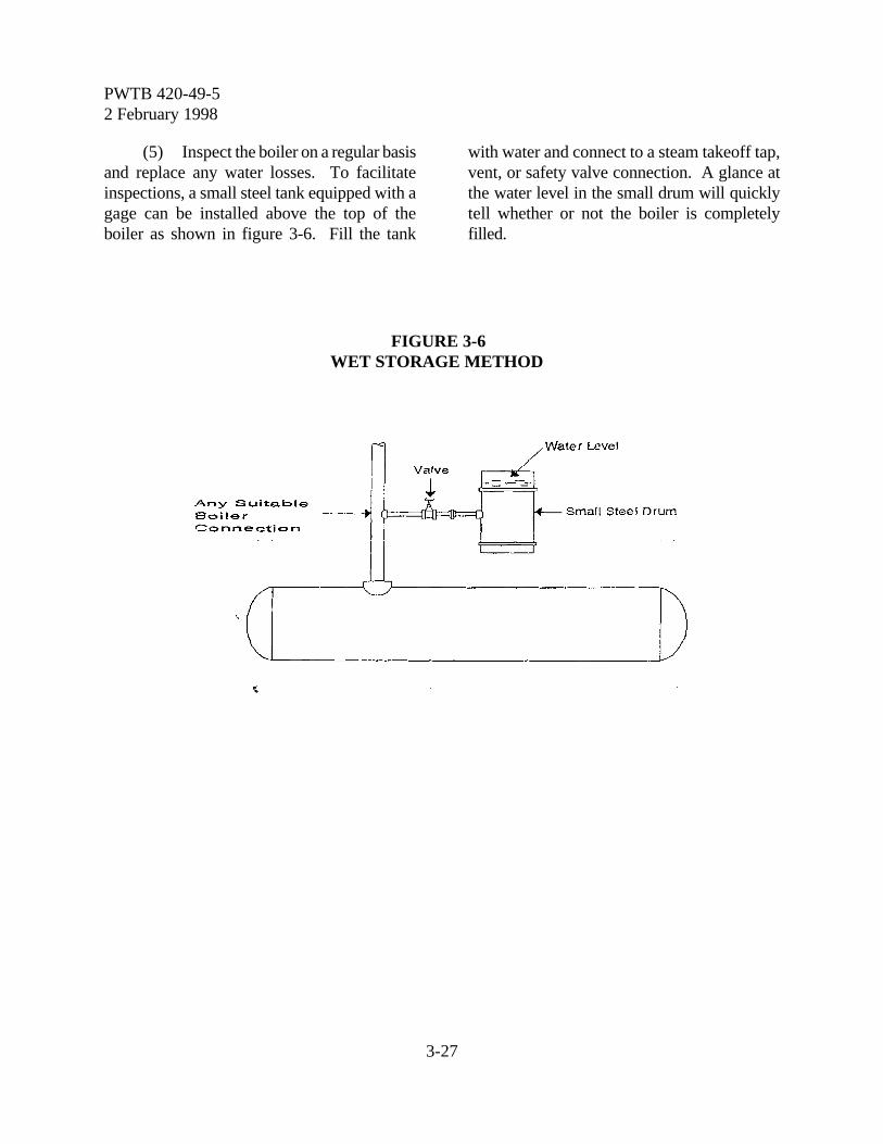
PWTB 420-49-52 February 1998
3-27
FIGURE 3-6WET STORAGE METHOD
(5) Inspect the boiler on a regular basisand replace any water losses. To facilitateinspections, a small steel tank equipped with agage can be installed above the top of theboiler as shown in figure 3-6. Fill the tank
with water and connect to a steam takeoff tap,vent, or safety valve connection. A glance atthe water level in the small drum will quicklytell whether or not the boiler is completelyfilled.
PWTB 420-49-52 February 1998
4-1
Chapter 4
Cooling Towers
Section IGeneral Information
4-1. Open recirculating system defined:a. Definition. An open circulating water
system includes the units where heat is to beremoved, the cooling water distribution, thereturn system, and the cooling tower. Heat,picked up in the recirculating water, istransferred from the cooling water to theatmosphere in a cooling tower. This requiresthe exposure of the water to a great quantityof air. The water also is cooled to a lesserextent, by conduction; that is, by the differencein temperature between the water and the air.Additional water (called makeup) must beadded to replace the water lost throughevaporation to maintain a constant operatingvolume of water in the cooling system. Aportion of the cooling water must bedischarged to the sewer as waste (calledblowdown) to maintain an adequate quality ofwater. Makeup water added to the coolingsystem must also replace this loss. Thecooling system will operate most efficientlywhen the recirculating water is properlytreated on a regular basis. This will result inreduced operating, maintenance, andreplacement costs.
b. Type of cooling towers: (1) Natural draft dowers: Air flow
through the tower is achieved without fans.Air flow across the falling water depends onthe wind conditions. Injecting water into thetower with spray nozzles improves efficiencyby bringing more water drops in contact withair.
(2) Forced draft towers: These
towers use one or more fans to blow air upthrough the tower fill against the flow offalling water. Drift eliminators are installed toprevent water entrained in the air from leavingthe system.
(3) Induced draft towers: Thesetowers use one or more fans to draw air acrossthe falling water. The air flows either cross-flow or counter-flow to the falling waterdrops. Drift eliminators are also installed.
c. Typical cooling towers at Armyinstallations. Cooling towers at Armyinstallations are mostly the induced draft cross-flow variety. They typically range in size from25 to 200 ton capacity.
4-2. Fundamental parts of a coolingtower. A simple cooling tower is shown infigure 4-1. The major parts of the towerinclude:
a. Basin and cold well. The basin is theportion of the tower below the cooling sectionor the coil section used for collecting andretaining circulating water and adding makeupwater. The cold well is a deepened portion ofthe basin that contains distribution pumps.
b. Louvers. These are members installedhorizontally on the sides of a tower wall toprovide openings through which air enters thetower. These are usually at an angle to thedirection of air flow.
c. Fill. The fill is the part of a tower whichintercepts the downward fall of water atregular intervals, forming splash surfaceswhich cause the water to breakup into smallerdroplets for the air-water contact. The towerfill commonly includes mist eliminators whichare internal structures designed to prevent
PWTB 420-49-52 February 1998
4-2
transport of the fine water droplets out of thetower.
d. Distribution and fan deck. The deckon top of a cooling tower is used to distributereturn flow to the tower fill and to support thefan housing. The stack is the structure(typically a cylinder) that encloses the fandischarge of an induced draft tower.
e. Cell. This is the smallest subdivision ofa complete cooling tower that can operate asan independent unit.
4-3. Objective of cooling water treatment:a. The open circulating cooling-tower
system has a greater potential for all types ofproblems associated with deposits, corrosionand microbiological organisms. Theseproblems are magnified in an open system forseveral reasons, including:
(1) Generally higher watertemperatures exist in the water systempromoting scale deposition and corrosion.
(2) The cooling tower acts as a hugeair scrubber, introducing microorganisms, dustand dirt in the circulating waters whichenhance the potential for fouling andcorrosion.
(3) Makeup water brings in morescale, deposit, and corrosion formingconstituents.
(4) Oxygen is continuously added tothe water as it passes through the coolingtowers increasing the potential for corrosion ofsteel and other metals in the system.
b. Regardless of the size and type ofcooling tower used, the system problems aresimilar, varying only in degree, and aredependent on the water used and the materialsof construction. All problems fall into threemain categories - deposit formation, biologicaldeposition, and corrosion. While problemscaused by these occur primarily in the system
heat exchangers, they can also occur in allwater-carrying lines, in the cooling tower, andin other system components that come incontact with the cooling water. Solutions tothese three problem areas are covered insections III, IV, and V of this chapter,respectively.
c. Knowing the water quality is an essentialelement in determining the type of treatment touse in a recirculating cooling water system.Before beginning a water treatment program,the makeup water should be analyzed todetermine its potential for scaling or corrosionin the system. Several scaling indices havebeen developed to predict a water's scalingtendency. These are explained in paragraph 4-11 and appendix B.
Section IICooling Tower Operating
Calculations
4-4. Principles of cooling toweroperations. The only function of a coolingtower is to cool warm water. The coolingwater circulates to operating units where itpicks up heat while cooling or condensing oneor more process streams and the resultingwarm water is returned to the cooling tower.The warm water is cooled by intimate contactwith air as it flows down through the tower.Two processes are involved. Conductiontransfers sensible heat from water to the coolerair, cooling the water and warming the air.This accounts for 20 to 30 percent of the totalcooling. The remaining cooling is the result ofevaporation of about 1 to 2 percent of therecirculating water. It takes approximately1,000 BTU to evaporate one pound of water.These BTU are supplied by the main body ofwater. If this amount of heat is extracted from1,000 pounds of water, the temperature of the
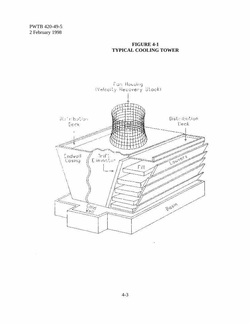
PWTB 420-49-52 February 1998
4-3
FIGURE 4-1TYPICAL COOLING TOWER
PWTB 420-49-52 February 1998
4-4
recirculating water will drop 1oF. If it isextracted from 100 pounds of water, the watertemperature will drop 10oF. This accounts forthe remaining 70 to 80 percent of the totalcooling. The water lost by evaporation mustbe replaced. Water also has to be added toreplace water lost through tower drift (loss ofwater from the tower as a fine mist), leaks inthe system, and water discharged asblowdown. Water added to the cooling towerto replace all these losses is known as makeup.A simple cooling system is shown in figure 4-2with makeup water and system lossesindicated.
4-5. Relationship between evaporation,blowdown, and makeup. The operation ofcooling towers can be described by therelationship between evaporation, blowdown,and makeup. Makeup must equal blowdownplus evaporation to maintain a constantoperating level in the system, or:
M = B + Ewhere: M = makeup water, gallons per day (gpd)
B = blowdown, gpdE = evaporation, gpd
NOTE: Blowdown (B) includes discharge tosewer, drift loss, and consumption in thesystem.
4-6. Cycles of concentration. A commonterm used in describing the performance ofcooling tower water systems is the cycles ofconcentration (COC). This term gives therelationship between the makeup waterquantity and blowdown quantity.
a. Definition. COC is defined as:
C = M ÷ B
where: C = COC, no unitsM = makeup water, gpdB = blowdown losses, gpd
b. Measuring COC. Both the makeupand blowdown must be know to determineCOC. However, COC can be estimated fromthe conductivity of the recirculating water andthe conductivity of the makeup (note theblowdown will have the same conductivity asthe recirculating water). The COC can beestimated using other water characteristicssuch as chlorides. The relationship is:
BFmho BclC = ____ or MFmho Mcl
where: C = COC, no unitsBFmho = conductivity of blowdown (recirculating water),
micromhos (Fmho)MFmho = conductivity of makeup water, FmhoBcl = chlorides in blowdown, ppmMcl = chlorides in makeup water, ppm
Example 4-1:1. The measured conductivity of the
blowdown (recirculating water) is 800micromhos; with the makeup 300micromhos.
2. The COC is:
BFmhoC = MFmho
800C = = 2.67
300
c. Controlling COC. A simple rulesometimes overlooked:
(1) To increase COC, decreaseblowdown.
(2) To decrease COC, increaseblowdown.
d. Relationship between COC andmakeup. The COC and makeup requirementsare related to the temperature drop across acooling tower and the recirculating rate of thetower. This is shown in figure 4-3 for arecirculating tower with temperature drops of10EF, 20EF, and 30EF. The significance of

PWTB 420-49-52 February 1998
4-5
FIGURE 4-2SIMPLE COOLING SYSTEM WITH MAKEUP AND LOSSES
PWTB 420-49-52 February 1998
4-6
these curves is to show that the makeuprequirement decreases very rapidly as the COCis increased to about 4 or 5, with lowerincremental reductions at higher COC.
4-7. Relationship between blowdown,evaporation, and cycles of concentration.The cooling water evaporation loss is used tocalculate the blowdown rate that needs to bemaintained in order to operate at a desiredCOC.
a. The relationship between blowdown,evaporation, and COC is as follows:
B = E ÷ (C - 1)where: B = blowdown, gpd (or gpm)
E = evaporation, gpd (or gpm)C = COC, no units
b. This formula is derived as follows:
(1) M = B + E from paragraph 4-5(2) C = M ÷ B from paragraph 4-6a(3) C = (B + E) ÷ B from equation (1)(4) C = 1 + (E ÷ B) rearranging equation (3)(5) (C - 1) = E ÷ B rearranging equation (4)(6) B = E ÷ (C - 1) rearranging equation (5)
c. If evaporation is known, the blowdownrequired for a given COC can be calculated.The evaporation can be estimated using simplerule of thumb estimates:
(1) For a typical recirculating watersystem, approximately 1 percent of the coolingwater is evaporated for every 10oFtemperature drop in the cooling water as itpasses through the tower.
E = 0.01 x recirculating rate x T-drop oF ÷ 10oF
Example 4-2:1. A cooling system operates at 5,000 gpm.
The temperature drop through the toweris 14oF.
2. The evaporation estimate is:
E = 0.01 x 5,000 gpm x 14oF ÷ 10oF = 70 gpm
(2) For an air conditioner coolingtower, the evaporation rate is approximately:
(a) One and one-half (1.5) gallonsper hour per ton (gal/hr/ton) for centrifugal orreciprocating air conditioners.
(b) Three (3) gal/hr/ton for anabsorption air conditioners.
Section IIIDeposit Formation & Control
4-8. Types of deposits. Deposit problemsare usually divided into two categories - scaleand fouling. Deposits of both types interferewith heat transfer in the heat exchanges,thereby reducing their efficiency.
4-9. Causes of scale. Scale is the depositionon heat transfer surfaces and in flow lines ofmaterial normally in solution in water. Aswater is evaporated in a cooling tower, thedissolved solids concentration becomes greateruntil the solubility of a particular salt isexceeded. When this happens in an untreatedcooling water system the salt will crystallize onany surface in contact with the water,especially on heat transfer surfaces.
a. The most common scaling materials arecalcium phosphate, calcium carbonate, calciumsulfate, and silica, not necessarily in that order.Magnesium silicate scale is also possible undercertain conditions. Most salts, including silica,are more soluble in hot water than in cold.However, most calcium salts, includingcalcium phosphate, calcium sulfate, andcalcium carbonate, are more soluble in coldwater than in hot. The water temperature willincrease as recirculating water passes throughthe cooling system. As a result scale may formanywhere in the system, but most likely onheat exchanger surfaces.
b. The concentration of salts in the makeup
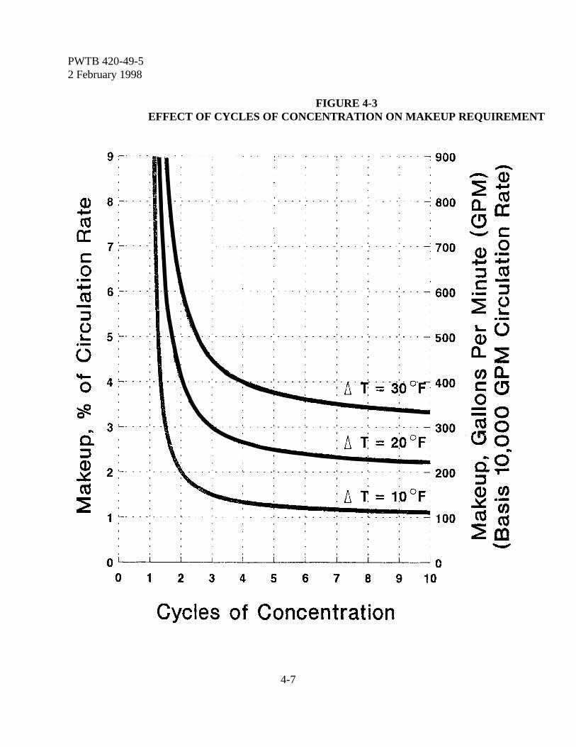
PWTB 420-49-52 February 1998
4-7
FIGURE 4-3EFFECT OF CYCLES OF CONCENTRATION ON MAKEUP REQUIREMENT
PWTB 420-49-52 February 1998
4-8
C / 110000TA x Mca
C /(105) x (9.8 & BpH)
Mca
C / 1250000Mca x Msu
C / 150Msi
water can be measured. Also, it is possible tocalculate the evaporation in the system. Byselecting an upper limit for the concentrationof solids in the system (as reflected byconductivity), it is possible to calculate theoptimum COC of an untreated system.Blowdown then can be estimated to maintainthis level using the relationship between COC,evaporation, and blowdown.
4-10. Determining scaling limits. Theupper limit for dissolved solids to preventscaling in an untreated system must be setbased on the types of scales that can form.The amounts of dissolved materials should bemaintained as close to this level as possible inorder to minimize the system blowdown. Thisis controlled by maintaining the COC in thesystem at a level that is equal to the lowestCOC allowable for any one of the salts. Theoperating COC can be increased with propercooling water treatment.
a. Calcium carbonate COC. Theprediction of calcium carbonate scale dependson the alkalinity and calcium hardness of themakeup.
where: C = COCTA = total (M) alkalinity (as CaCO3) in makeup, ppmMca = calcium hardness (as CaCO3) in makeup, ppm
b. Calcium phosphate COC. Whengreater than 5 ppm of orthophosphate arepresent in the circulating water, the COC atwhich calcium phosphate scale will form canbe calculated:
where: C = COC, no units
BpH = measured pH in blowdown, pH unitsMca = calcium hardness (as CaCO3) in makeup, ppm
c. Calcium sulfate COC. The COC atwhich calcium sulfate scale will form can becalculated:
where: C = COC, no unitsMca = calcium hardness (as CaCO3) in
makeup, ppmMsu = sulfate (as SO4) in makeup, ppm
d. Silica COC. The solubility of silica isabout 150 ppm at the temperature rangeencountered in most cooling towers. Theallowable COC is:
where: C = COC, no units150= solubility of silica, ppmMsi = silica (as SiO2) in the makeup, ppm
e. Determining the COC that controloperation. In untreated systems the smallestcalculated COC, using the relationships forthese salts, is the controlling factor. This isdue to the fact that, as the system operates, thematerial that has the lowest calculated COCwill be the first to come out of solution, andtherefore, is the most likely to form a scaledeposit in the system. The COC in the systemmust be kept at a level that is lower than thesmallest COC calculated for calciumcarbonate, calcium phosphate, calcium sulfate,and silica to prevent these materials fromforming a deposit.
Example 4-3:1. A cooling tower makeup has the
following composition:
PWTB 420-49-52 February 1998
4-9
COC / 11000060 x 100
/ 4.3
COC / 1250000100 x 60
/14.4
COC / 150 ÷ 14 ' 10.7
Calcium Hardness 100 ppmTotal (M) Alkalinity 60 ppmSulfate 60 ppmSilica 14 ppmAt what COC can the system operatewithout water treatment?
2. Based on calcium carbonate:
3. Based on calcium sulfate:
4. Based on silica:
5. The COC determined for calciumcarbonate is lowest at 4.3, and thistherefore controls the system operation.Scaling should not occur provided thesystem is operated without watertreatment at less than 4.3 COC. Use ofa phosphonate or a polymeric antiscalantwill increase the number of allowableCOC for calcium carbonate. The COCand hence the blowdown will then bedetermined by a calculated "scalingindex".
4-11. Use of scaling indices. The mostcommon scale found in cooling tower systemsis calcium carbonate in the form of calcite.The solubility of calcium carbonate, whichdecreases with an increase in temperature, is acomplex function of temperature, totaldissolved solids (TDS), calcium hardness, totalalkalinity, and pH. To predict if scale would
form in the hotter sections of a cooling watersystem, researchers have over the yearsdeveloped scaling indices.
a. Langelier and Ryznar indices. W.F.Langelier derived a method to calculate thecalcium carbonate scale-forming or scale-dissolving tendency of a water. The method isbased on determining the saturation pH (pHs),the pH at which calcium carbonate will start tocome out of solution. If the measured pH ofthe water is greater than its pHs, the water hasa scale-forming tendency; if it is less than itspHs, it has a scale-dissolving tendency. Theformula pH minus pHs is known as theLangelier Index or Langelier Saturation Index(LSI). A positive value indicates a scale-forming tendency. A negative value indicatesa scale-dissolving tendency. J.W. Ryznar laterdevised a more sensitive formula, 2pHs - pH,known as the Ryznar Index or the RyznarStability Index (RSI). A value of 6 indicates astable water. A value less than 6 indicates ascale-forming tendency and greater than 6indicates a scale-dissolving tendency. Theindices have also been used to try to estimatethe degree to which calcium carbonate willform. The more positive the LSI, the greaterthe scale formation. For the RSI, however,the smaller the index, the greater the scaleformation. In some cases, the LSI and RSIcan give conflicting predictions with the samewater.
b. Practical (Puckorius) scaling index.Paul R. Puckorius and J. Maxey Brookedeveloped a modified version of the RSI togive a better and more consistent indication ofscaling conditions of cooling water. Known asthe Practical Scaling Index (PSI), it takes intoconsideration the effect that the total alkalinityof the cooling water has on the measured pHvalue. Since pH is often buffered by otherions, it does not always relate correctly to
PWTB 420-49-52 February 1998
4-10
bicarbonate alkalinity. Rather than using themeasured pH in calculating the PSI, anadjusted or equilibrium pH (pHeq) is used: PSI= 2pHs - pHeq. As with the RSI, a PSI of 6indicates a stable water and a value lower than6 indicates a scale-forming tendency. Withoutthe use of a scale control treatment, a coolingtower with a PSI of 6 to 7 should operatescale free. However, a PSI of greater than 6indicates that corrosion may occur.Information on calculating the PSI is providedin appendix B.
4-12. Scale control. There are three basicmethods for preventing the formation of scalein cooling water systems:1) Remove the scaling material from the water
prior to use,2) Keep the scale-forming materials in
solution, and 3) Allow the scaling material to precipitate as
a removable sludge, rather than as harddeposits.
All three methods are authorized for use onArmy installations. Inhibition of calciumscales, those most common in cooling towersystems, can be achieved by lowering the pHof the recirculating water (with the addition ofacid), or by the addition of a calcium scaleinhibitor (HEDP or AMP) which allows thePSI to be carried at a lower value (higherCOC) without scaling occurring, or both.Because of the hazards associated withhandling strong acids and the potential damagefrom an acid spill, the use of acid in coolingtowers is not recommended. If thecharacteristics of a water at a specific locationindicate the need to use acid, contactUSACPW (CECPW-ES) at Fort Belvoir,Virginia, for guidance.
a. Calcium carbonate control. Calciumcarbonate normally results from the
breakdown of calcium bicarbonate, a naturallyoccurring soluble salt. The degree of scalingdepends primarily on the levels of calciumhardness and bicarbonate alkalinity in thecooling water. The breakdown of calciumbicarbonate increases with temperature. Twophosphonates most frequently used for calciumcarbonate control in recirculating coolingtower systems are AMP (Aminotrimethylenephosphonic acid) and HEDP (1-Hydroxyethylidene 1,1-Diphosphonic acid).The chemical reaction of both are similar,however, HEDP is more stable at chlorinelevels normally found in cooling towers. Theuse of 3 to 5 ppm HEDP will increase thesolubility of calcium carbonate by a factor ofthree. Rather than operating at a PSI of 6.0 asin an untreated system, the cooling tower willbe able to operate at a PSI of 4.0 withoutpotential scaling (refer to paragraph 4-11 andappendix B). However, the use of HEDP inthe absence of calcium and magnesiumhardness (or at very low levels), can increasethe corrosion of both mild steel and copper.
b. Calcium phosphate control. Calciumphosphate scale is common in cooling watersystems treated with a phosphate-basedcorrosion inhibitor program. Calciumphosphate is also less soluble at higher pH andtemperatures. If the calcium hardness is 500ppm and the pH is above 7.0, it is likely tocause scaling even at the low level of 5 ppmphosphate. Calcium phosphate solubility canbe increased by a factor of a little less thanthree with the addition of 4 ppm phosphonate(HEDP).
c. Calcium sulfate control. Calciumsulfate results from high concentrations ofcalcium and sulfate ions in the recirculatingwater. Calcium sulfate is the most soluble ofthe scale-forming calcium salts found incooling towers (calcium chloride is extremely
PWTB 420-49-52 February 1998
4-11
soluble). This means that calcium sulfate scalewill not form unless some calcium hardnessremains after it reacts with all the carbonate inthe water. Still, calcium sulfate scale mayoccur when the recirculating water containscalcium hardness in the range of 300 to 500ppm as CaCO3 and sulfate in the range of 500to 700 ppm SO4. The addition of 3 to 5 ppmof a phosphonate (HEDP) or other appropriatecalcium inhibitors will allow almost three timesthe level of calcium sulfate to remain insolution.
d. Magnesium silicate control. Formationof magnesium silicate is possible under certainconditions. Magnesium first reacts withhydroxyl ions (OH-) to form magnesiumhydroxide, which then reacts with dissolved orcolloidal silica to form magnesium silicate.Since silica solubility increases withtemperature, this scale will usually form in thecoldest portion of the system.
e. Silica control. Nothing can be done toincrease the solubility of silica above 150 ppm.Since silica is more soluble in hot water than incold water, it will first deposit on the coolingtower slats rather than in the heat exchanger.The slats will become coated with a white,sometimes sparkling deposit. If this occurs,increase blowdown, which decreases cycles ofconcentration. This should stop additionalscale formation. If the concen-tration of silicain the makeup water is above 30 ppm, itusually controls the operation of the system(maximum 5 COC). If it is too high forefficient cooling tower operation, it can bereduced in or removed from the makeup waterby treatment (chapter 2).
4-13. Causes of fouling. Fouling is thedeposition, usually on heat transfer surfaces, ofmaterials normally in suspension. Suchmaterials include silt and other suspendedsolids brought into the system with the
makeup water; dust and pollen scrubbed out ofthe air passing through the tower; productleakage; corrosion products; and both livingand dead microbiological materials. Slime-producing organisms can be particularlyserious as a source of fouling. They canmultiply and grow until they completely pluga heat exchanger in a matter of days ifconditions are favorable for the organisms.
4-14. Fouling control. Fouling bynonliving matter can be controlled by theaddition of a dispersant such as polyacrylate.The addition of about 4 ppm will keep foulantsin suspension and prevent them fromdepositing on heat transfer surfaces.Prevention of fouling by living matter isdiscussed in paragraph 4-16.
Section IVMicrobiological Deposits And Control
4-15. General information. Microbiological problems are generallyreferred to as slime deposits. They result fromthe presence of microorganisms such as algae,bacteria, and fungi. These can grow within acooling system, coating all pipe and heatexchanger surfaces. The gelatinous slimesproduced by many microorganisms can trapsediments, thus encouraging fouling and scale.Even corrosion can be caused by certainorganisms that produce corrosive byproducts.
a. Algae: Tiny green plants, usually foundgrowing in masses on top and on sides ofcooling towers. They are not harmful untilthey die. Then they will slough off, becomepart of the suspended matter in the circulatingwater, and may cause fouling. Algae also mayprovide a breeding place for bacteria.
b. Bacteria: Microscopic one-celledorganisms. Most bacteria are suspended in thecooling water and do not harm the cooling

PWTB 420-49-52 February 1998
4-12
system. However, some can cause fouling andcorrosion.
(1) Slime-forming bacteria: Bacteriathat can grow in colonies on almost anysurface covered by the water. These slimecolonies can grow so large that they canrestrict water flow and heat transfer. Theyalso may promote corrosion. The presence ofslime-formers can be tested by feeling insidethe cooling tower just below the water level.If there is slime in the system, it can usually befelt there.
(2) Sulfide-producing bacteria:Bacteria that can grow under slime masses.They can produce hydrogen sulfide which isvery corrosive. They may be detected in asystem where the underside of the slime layeris a metallic black color, or the odor of rotteneggs is present.
c. Fungi: Microscopic plants that do notrequire sunlight. They can attack wood incooling towers. Their control requires specialtreatment of the wood, usually before theconstruction of the tower. Their control in anoperating system requires special techniques.
4-16. Microbiological control. Chemicaltreatment is the method used on Armyinstallations for microbiological control.Biocides used to control microbiologicalgrowth fall into two broad categories -oxidizing and nonoxidizing. The choicebetween these two depends on various factors.A major consideration is limitation ondischarge of toxic substances. Also, operatingparameters of the cooling tower, such astemperature, pH, and system design, must beconsidered in a decision involving oxidizingand nonoxidizing biocides. Control programsaim for 99 percent reduction of organismpopulations. This is done by using one ormore biocides, sometimes including thecombination of both oxidizing and
nonoxidizing biocides. The use of oxidizingbiocides requires careful control of theiraddition to cooling water. If this cannot beassured, it may be best to eliminate their use toavoid problems, such as delignification ofwood. Besides being capable of killing a largepercentage of microorganisms, the selection ofbiocides must also consider cost. The primaryfactor affecting cost is the frequency ofapplication to provide the desired control.Normal slug dosage should be applied anaverage of one to three times a week, unlessfouling is particularly severe. The mostimportant aspect of biofouling control is tomatch the biocide to the problem organism.
a. Algae control. Algae can be controlledby preventing their growth or by destroyingthe plants that have grown.
(1) Algae need light to survive becausethey are plants. They often can be kept undercontrol by covering the upper decks of thetowers.
(2) Calcium hypochlorite sprinkled onthe upper deck will kill algae. However, it willadd calcium to the circulating water increasingthe possibility of scale and could attack thewood.
b. Bacteria control. (1) Bacteria control with chlorine:
Chlorine is the most familiar and effectiveindustrial biocide. When chlorine gas isintroduced to water, it hydrolyses to formhydrochloric and hypochlorous acid. It is thelatter that is an oxidizing biocide, providedthere is little or no deionization. Thehypochlorous acid state is favored by low pH.At a pH of 5.0, there is very little ionization; ata pH of 7.5 there are approximately equalamounts of hypochlorous acid and the ion.Chlorine is less effective as a biocide at pH of9.5 or greater, because of the total lack ofionization. Generally, a pH range of 6.5 to 7.5is considered practical for chlorine, or chlorine
PWTB 420-49-52 February 1998
4-13
based microbial-control programs, since alower pH would increase system corrosion.Because of safety concerns when handlinggaseous chlorine, controlling the feed of thegas, and the increasing concern for theenvironmental effects of escaping residualchlorine, gaseous chlorine is seldom used onArmy installations for treating cooling towers.
(2) Alternatives to chlorine: Some ofthe many biocides available, other thanchlorine, are listed in table 4-1. Selection of abiocide (or combination of biocides) should bebased on the chemical treatment program usedand on local factors. This may includebiocides that are not on the list in table 4-1,provided they are approved by the installationenvironmental engineer.
c. Ozone (O3). Ozone is a very strongoxidizing biocide which would provideeffective control of microorganisms in coolingtower systems, if properly applied. However,because of safety and operational problemsassociated with its manufacture and use, andthe resulting high cost, it is not an economicalmethod for microbiological control in coolingtowers. Unsubstantiated claims have beenmade that ozone provides total protectionagainst scale, fouling and microbiologicalproblems in cooling towers. Its use on Armyinstallations is not authorized (refer toparagraph 4-26).
4-17. Legionnaires’ disease.Legionnaires’ Disease (Legionellosis) is arespiratory disease (atypical pneumonia) whichstrikes certain individuals exposed to a mist ofwater laden with the bacteria LegionellaPneumophila. There is a possibility that acooling tower at an Army installation couldbecome infected with the bacteria. Thepresence and density of LegionellaPneumophila cannot be detected with normalmicrobiological testing done at installation
level. Samples need to be sent to a laboratorywith the capability to conduct such tests. Ifinfection of a tower is suspected, theinstallation's medical officer will identify theneed and procedures to disinfect the coolingtower. A typical procedure is to add a gallonof chlorine release agent (sodium hypochlorite)and a pound of trisodium phosphate (or anonfoaming household detergent) to thecooling tower sump for every 100-toncapacity. This should be done every 2 days fora total of 6 days.
Section VCorrosion In Cooling Systems
4-18. Definition of corrosion.Corrosion is the deterioration of a metal thatmay occur because it is in contact with thecooling tower water. The corrosion occurswhen an electric current flows form one partof the metal (anode) through the water(electrolyte) to another part of the metal(cathode). Corrosion takes place where thecurrent leaves the metal (at the anode). Formsof corrosion associated with industrial watersystems are illustrated in figure 4-4.
a. Galvanic corrosion. When twodifferent metals are coupled together the metalhigher on the galvanic series becomes theanode and will corrode. In the case of steeland copper, for example, the steel becomes theanode and corrodes. If steel and zinc arecoupled together at temperatures normallyfound in cooling tower systems, the zincbecomes the anode and corrodes. One of themost common causes of galvanic corrosionfound in cooling water systems is thecombination of steel and copper alloy metals incontact with each other. Dissolved copperresulting from copper corrosion can plate outon steel surfaces setting up a galvanic cell.Pitting corrosion is the result. Since it is
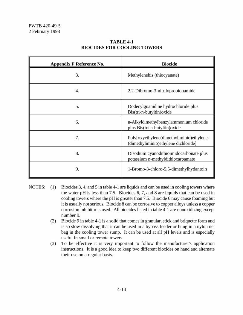
PWTB 420-49-52 February 1998
4-14
TABLE 4-1BIOCIDES FOR COOLING TOWERS
Appendix F Reference No. Biocide
3. Methylenebis (thiocyanate)
4. 2,2-Dibromo-3-nitrilopropionamide
5. Dodecylguanidine hydrochloride plusBis(tri-n-butyltin)oxide
6. n-Alkyldimethylbenzylammonium chlorideplus Bis(tri-n-butyltin)oxide
7. Poly[oxyethylene(dimethyliminio)ethylene-(dimethyliminio)ethylene dichloride]
8. Disodium cyanodithioimidocarbonate pluspotassium n-methyldithiocarbamate
9. 1-Bromo-3-chloro-5,5-dimethylhydantoin
NOTES: (1) Biocides 3, 4, and 5 in table 4-1 are liquids and can be used in cooling towers wherethe water pH is less than 7.5. Biocides 6, 7, and 8 are liquids that can be used incooling towers where the pH is greater than 7.5. Biocide 6 may cause foaming butit is usually not serious. Biocide 8 can be corrosive to copper alloys unless a coppercorrosion inhibitor is used. All biocides listed in table 4-1 are nonoxidizing exceptnumber 9.
(2) Biocide 9 in table 4-1 is a solid that comes in granular, stick and briquette form andis so slow dissolving that it can be used in a bypass feeder or hung in a nylon netbag in the cooling tower sump. It can be used at all pH levels and is especiallyuseful in small or remote towers.
(3) To be effective it is very important to follow the manufacturer's applicationinstructions. It is a good idea to keep two different biocides on hand and alternatetheir use on a regular basis.
PWTB 420-49-52 February 1998
4-15
difficult to protect the steel from the platingaction, it is necessary to treat the copper tokeep it from corroding.
b. Crevice corrosion. A crevice can existat many locations in a cooling tower, such asat the contact point of two steel plates boltedtogether. Flow is restricted in a crevice, andas a result, oxygen is consumed faster than itcan be replenished. The metal in the crevicethen becomes the anode and corrodes. This isa form of concentration cell corrosion.
c. Deposit corrosion. The underside of adeposit caused by fouling, bacterial slime, oreven debris acts in much the same way as theinside of a crevice. The metal under thedeposit may become anodic and corrode. Thisis another form of concentration cellcorrosion.
d. General corrosion. Even a single pieceof steel will have cathodic and anodic areasdue to differences in impurities and stresses.Further, a cathodic area will periodicallychange to anodic and vice versa, causing thesteel to corrode at a more or less uniform rate.
4-19. Corrosion rates. Corrosion rates aremeasured in mils per year (mpy). A mil is one-thousandth of an inch. An assessment ofcorrosion rates in cooling water systems isprovided in table 4-2. Some factors that cancause an increase in corrosion rates and theirpotential for control by the water systemoperator are shown in table 4-3.
4-20. Methods of corrosion control:a. Galvanic and crevice corrosion.
Galvanic and crevice corrosion are designproblems and cannot be entirely eliminated bythe water system operator. However, aproperly operated water treatment programwill help reduce these types of corrosion.
b. Deposit corrosion. Deposit corrosion iscontrolled by keeping the system clean.Fouling is prevented by the use of dispersants
as discussed under deposit control. Bacterialslime is prevented by the use of biocides asdiscussed under microbiological control.Debris can be kept out of the system by theuse of screens in the cooling tower sump.
c. General corrosion. General corrosionis controlled by the use of inhibitors. Theseare chemicals which form a film on the coolingtower metal. The film must be thick enough toinsulate the metal from the water to preventthe current flow, but thin enough not tosignificantly interfere with the heat transferthrough the metal.
(1) Anodic inhibitors such asorthophosphate, nitrite, molybdate, andsilicates coat the anode and directly controlcorrosion by preventing the reaction thatresults in corrosion. Cathodic inhibitors suchas zinc, polyphosphates, and polysilicates, coatthe cathode and indirectly prevent corrosion byinterfering with the link required between thecathode and anode.
(2) Using only an anodic inhibitor willnot give complete protection from corrosionbecause inhibitors do not always give 100percent coverage. The unprotected areas willcorrode at a much faster rate than the largerareas, resulting in pitting attack.
(3) The best way to control generalcorrosion is to add both a cathodic and ananodic inhibitor.
d. Special corrosion control for copperand copper alloys. The protection of copperand copper alloys requires the use oftolyltriazole (TT), which can be added to thesystem separately or in a blend of othertreatment chemicals. The recommendedapplication rate is 0.1 pound per day per 100ton capacity of the tower.
Section VIPutting It All Together
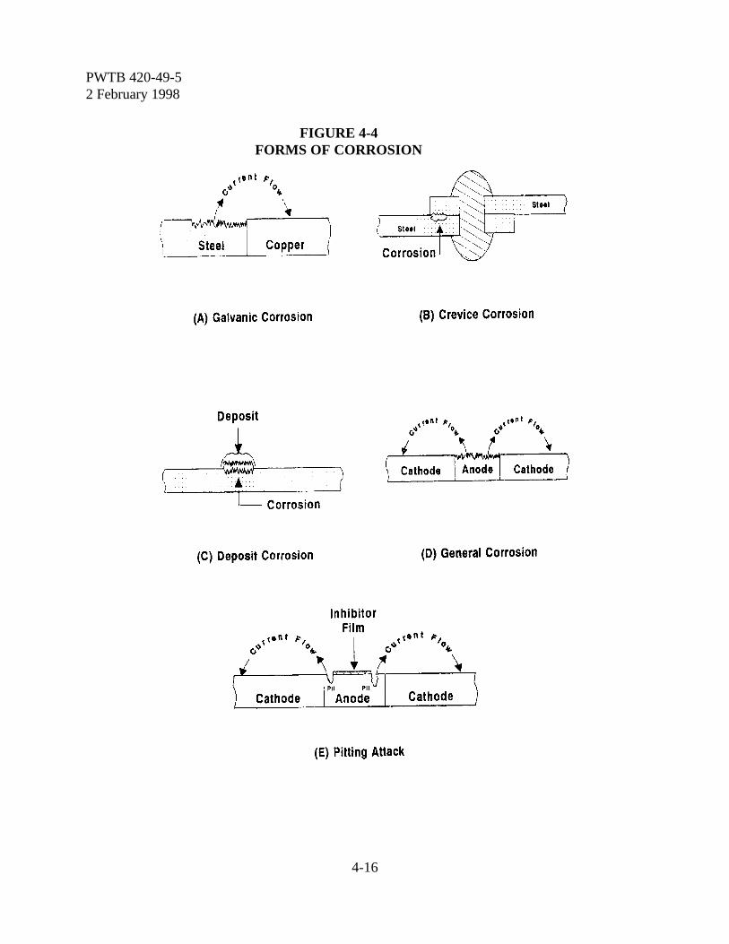
PWTB 420-49-52 February 1998
4-16
FIGURE 4-4FORMS OF CORROSION
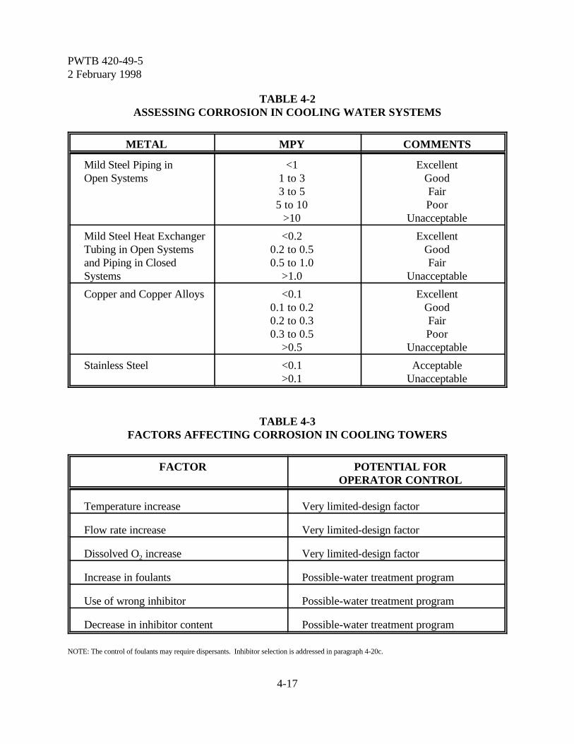
PWTB 420-49-52 February 1998
4-17
TABLE 4-2ASSESSING CORROSION IN COOLING WATER SYSTEMS
METAL MPY COMMENTS
Mild Steel Piping inOpen Systems
<11 to 33 to 5
5 to 10>10
ExcellentGoodFairPoor
Unacceptable
Mild Steel Heat Exchanger Tubing in Open Systemsand Piping in ClosedSystems
<0.20.2 to 0.50.5 to 1.0
>1.0
ExcellentGoodFair
Unacceptable
Copper and Copper Alloys <0.10.1 to 0.20.2 to 0.30.3 to 0.5
>0.5
ExcellentGoodFairPoor
Unacceptable
Stainless Steel <0.1>0.1
AcceptableUnacceptable
TABLE 4-3FACTORS AFFECTING CORROSION IN COOLING TOWERS
FACTOR POTENTIAL FOROPERATOR CONTROL
Temperature increase Very limited-design factor
Flow rate increase Very limited-design factor
Dissolved O2 increase Very limited-design factor
Increase in foulants Possible-water treatment program
Use of wrong inhibitor Possible-water treatment program
Decrease in inhibitor content Possible-water treatment program
NOTE: The control of foulants may require dispersants. Inhibitor selection is addressed in paragraph 4-20c.
PWTB 420-49-52 February 1998
4-18
4-21. General information. A completetreatment program for cooling water may needto include treatment of the makeup water andfor the recirculating water.
a. Treatment of makeup water. It isnormal practice to use water from theinstallation supply for cooling tower makeupwithout additional treatment. There arespecial conditions where the treatment ofmakeup might be warranted, such as highlevels of iron, hardness, silica, or dissolvedsolids. Makeup treatment should be usedwhen such treatment will significantly reducethe cost of internal treatment, or whenimproved protection of the system warrantsthe cost. However, in general, there will notbe an advantage to using treated water if theCOC that can be carried by the system usinguntreated water is calculated to be greater thanthree.
b. Treatment of recirculating water. Treatment programs for cooling towerrecirculating water can be divided into twobasic categories; small towers (less than 25 toncapacity) and larger ones, e.g., medium sizetowers (25 to 100 ton) and large size towers(greater than 100 ton). In addition tocontrolling scale by adjusting the cycles ofconcentration through blowdown (covered inparagraph 4-22), recirculating water in thesetowers generally needs chemical treatment forcontrol of scale formation, fouling, corrosion,and microbiological growth. Treatmentchemicals and methods are individuallycovered in previous sections. Completechemical programs are covered in paragraphs4-23 and 4-24.
4-22. Scale control by adjusting COC.The COC of small, medium, and large coolingtowers may be controlled by blowdown toavoid high levels of silica and calcium salts that
can lead to their precipitation. This is done bymonitoring the blowdown and makeupconductivity to maintain the tower at a COCless than the smallest allowable COC for thesematerials (paragraph 4-10). This technique ofscale control applies to both treated anduntreated towers. The difference is that ratherthan operating an untreated tower at a PSI of6.0, for example, it would be possible tooperate the tower at a PSI of 4.0 (with acorresponding higher COC), if properlytreated.
4-23. Treatment program for smallcooling towers. A small cooling tower at anArmy installation typically will have a rating ofless than 25 tons. The treatment used forsmall towers also may be applied to isolatedmedium towers that must operate with verylittle operator control.
a. Treatment. Small systems can betreated by placing a nylon mesh bag containingabout 15 to 20 pounds of a slowly solublephosphate chemical in the cooling tower sump.If microbiological problems exist, a biocidesuch as item 9 in table 4-1 may be added.
b. Testing. The bag with chemicaltreatment should be checked weekly to ensurethat chemical remains available. Thefrequency for replacing the bag will vary, but1 to 2 months is typical.
4-24. Treatment programs for mediumand large cooling towers. The chemicaltreatment program for a large tower (typicallygreater than 100 tons) should include controlof scale, fouling, microbiological growth, andcorrosion. The treatment program for amedium tower (25 to 100 tons) should includethese controls where possible, or the treatmentprocedures in paragraph 4-23 for isolatedsystems. The optimum chemical treatment

PWTB 420-49-52 February 1998
4-19
program for cooling towers on an Armyinstallation depends on the quality of wateravailable, operating conditions of the towerand the environmental constraints placed onzinc and other treatment chemicals in theblowdown. Three treatment programs foundto be effective for typical cooling towerconditions are provided below. Thesetreatment programs provide for scale control,fouling control, and corrosion control (bothferrous metals and copper alloys). The coolingtowers will also most probably need biocidesfor microbiological control (refer to section IVof this chapter). Conditions at a particularArmy installation may require variation in thequantity or mix of the chemicals prescribed.
a. Zinc-Phosphonate program. Thisprogram can be used when zinc is allowed inthe blowdown. It is best to limit the hardnessof the makeup water to 140 ppm (as CaCO3)and the COC to about 3, although the programwill still provide some protection with higherhardness makeup water. Keeping the pH ofthe system below 8.0 will help preventformation of zinc hydroxide. The program willstill be effective at a higher pH but may require
more zinc. Operating limits and approximateamounts of chemicals required to maintainthese limits are shown in Table 4-4:
b. Zinc-Molybdate program. Thisprogram can be used when zinc is allowed inthe blowdown. Keeping the pH below 8.0 willhelp prevent formation of zinc hydroxide.However, the program will still be effective ata higher pH but may require more zinc. Zinc-stabilizing polymers may also be used.Operating limits and approximate amounts ofchemical required to maintain these limits areshown in Table 4-5:
c. Phosphonate-Polymer program. Thisprogram can be used where zinc, molybdate orother heavy metals are not allowed forenvironmental reasons. Keep the pH for thisprogram between 7.5 and 8.5 for best results.Operating limits are approximate amounts ofchemicals required to maintain these limits areshown in Table 4-6:
d. Specifications. Treatment chemicalspecifications for these programs are providedin table 4-7.
TABLE 4-4DOSAGES FOR ZINC-PHOSPHONATE PROGRAM
Limits Estimated Chemical RequirementPounds Per Day Per 100 Ton Tower
Capacity at 3 COC & 10oFªªt
3-5 ppm phosphonate 0.1 HEDP
1-2 ppm zinc (as Zn) 0.1 zinc sulfate
3-4 ppm polymer 0.1 polyacrylate
1-2 ppm TT 0.1 tolyltriazole
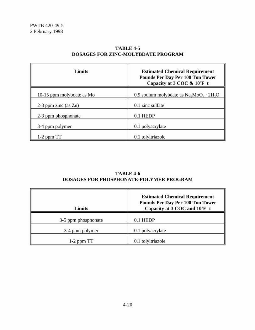
PWTB 420-49-52 February 1998
4-20
TABLE 4-5DOSAGES FOR ZINC-MOLYBDATE PROGRAM
Limits Estimated Chemical RequirementPounds Per Day Per 100 Ton Tower
Capacity at 3 COC & 10oFªªt
10-15 ppm molybdate as Mo 0.9 sodium molybdate as Na2MoO4 @ 2H2O
2-3 ppm zinc (as Zn) 0.1 zinc sulfate
2-3 ppm phosphonate 0.1 HEDP
3-4 ppm polymer 0.1 polyacrylate
1-2 ppm TT 0.1 tolyltriazole
TABLE 4-6DOSAGES FOR PHOSPHONATE-POLYMER PROGRAM
Limits
Estimated Chemical RequirementPounds Per Day Per 100 Ton Tower
Capacity at 3 COC and 10oFÎÎt
3-5 ppm phosphonate 0.1 HEDP
3-4 ppm polymer 0.1 polyacrylate
1-2 ppm TT 0.1 tolyltriazole
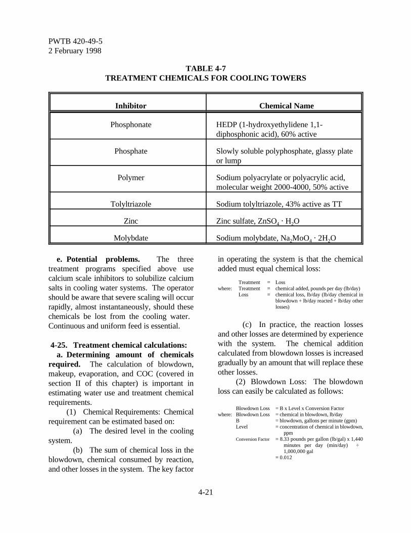
PWTB 420-49-52 February 1998
4-21
TABLE 4-7TREATMENT CHEMICALS FOR COOLING TOWERS
Inhibitor Chemical Name
Phosphonate HEDP (1-hydroxyethylidene 1,1-diphosphonic acid), 60% active
Phosphate Slowly soluble polyphosphate, glassy plateor lump
Polymer Sodium polyacrylate or polyacrylic acid,molecular weight 2000-4000, 50% active
Tolyltriazole Sodium tolyltriazole, 43% active as TT
Zinc Zinc sulfate, ZnSO4 @ H2O
Molybdate Sodium molybdate, Na2MoO4 @ 2H2O
e. Potential problems. The threetreatment programs specified above usecalcium scale inhibitors to solubilize calciumsalts in cooling water systems. The operatorshould be aware that severe scaling will occurrapidly, almost instantaneously, should thesechemicals be lost from the cooling water. Continuous and uniform feed is essential.
4-25. Treatment chemical calculations:a. Determining amount of chemicals
required. The calculation of blowdown,makeup, evaporation, and COC (covered insection II of this chapter) is important inestimating water use and treatment chemicalrequirements.
(1) Chemical Requirements: Chemicalrequirement can be estimated based on:
(a) The desired level in the coolingsystem.
(b) The sum of chemical loss in theblowdown, chemical consumed by reaction,and other losses in the system. The key factor
in operating the system is that the chemicaladded must equal chemical loss:
Treatment = Losswhere: Treatment = chemical added, pounds per day (lb/day)
Loss = chemical loss, lb/day (lb/day chemical inblowdown + lb/day reacted + lb/day otherlosses)
(c) In practice, the reaction lossesand other losses are determined by experiencewith the system. The chemical additioncalculated from blowdown losses is increasedgradually by an amount that will replace theseother losses.
(2) Blowdown Loss: The blowdownloss can easily be calculated as follows:
Blowdown Loss = B x Level x Conversion Factorwhere: Blowdown Loss = chemical in blowdown, lb/day
B = blowdown, gallons per minute (gpm)Level = concentration of chemical in blowdown,
ppmConversion Factor = 8.33 pounds per gallon (lb/gal) x 1,440
minutes per day (min/day) ÷ 1,000,000 gal
= 0.012

PWTB 420-49-52 February 1998
4-22
Example 4-4:1. A cooling tower with 5,000 gpm
recirculation has an 8oF temperaturedrop. The conductivity of the blowdown(recirculating water) is 1,200 micromhosand that of the makeup water is 300
micromhos. It is desired to maintain 100ppm treatment in the system. What isthe required blowdown? What will bethe makeup? How much chemical mustbe added each day?
2. Determine the evaporation in the system(paragraph 4-7c).
E = 0.01 x recirculating rate x (T drop oF) ÷ 10oF= 0.01 x 5,000 gpm x 8oF ÷ 10oF = 40 gpm
3. Determine COC in the system using theconductivity data (paragraph 4-6b).
BFmho 1200COC = = = 4.0
MFmho 300
4. Estimate system blowdown, based onCOC and evaporation (paragraph 4-7a).
B = E ÷ (C - 1) = 40 gpm ÷ (4 - 1) = 13.3 gpm
5. Determine makeup water(paragraph 4-5).
M = B + E = 40 gpm + 13.3 gpm = 53.3 gpm
6. Determine treatment chemical required.The chemical added to the system mustequal the chemical lost in the blowdown.The calculated chemical level might needto be increased in practice to account forchemical reaction and other losses, untilthe desired level is reached.
Blowdown = Loss x Level x Conversion Factor= 13.3 gpm x 100 ppm x 0.012= 16.0 lb/day
b. Feeding treatment chemicals. Theindividual chemicals identified in the threetreatment programs (paragraph 4-24) may bemixed in the proper proportions and added asa blend (mixture), preferably with a continuousfeed system. The cooling tower will probably
also need biocides (refer to section IV of thischapter).
Example 4-5:1. A cooling tower is treated with program
(1): 5 ppm phosphonate (HEDP), 2 ppmzinc, 4 ppm polyacrylate, and 2 ppmtolyltriazole.
2. For a 100 ton tower this requires:
HEDP 0.1 lb/day (approximately)Zinc Sulfate 0.1 lb/day (approximately)Polyacrylate 0.1 lb/day (approximately)Tolyltriazole 0.1 lb/day (approximately)
These components are sold in varioussolution strengths. Later adjustments inquantities may be necessary.
3. The proper mixture concentrations(percent by weight) are:
lbsHEDP % = x 100
lbs total
0.1= x 100
0.1+0.1+0.1 + 0.1
0.1= x 100 = 25%
0.4
0.1Zinc Sulfate = x 100 = 25%
0.4
0.1Polyacrylate = x 100 = 25%
0.4
0.1Tolyltriazole = x 100 = 25%
0.4
4. Cooling towers on Army installations arenormally fed continuously from a 55gallon drum or tank. To prepare a 3percent chemical solution add thefollowing to fifty gallons (416.5 pounds)of water:
PWTB 420-49-52 February 1998
4-23
3% x 416.5 = 12.50 total pounds of chemicals consistingof:
25% x 12.5 = 3.1 pounds HEDP25% x 12.5 = 3.1 pounds Zinc Sulfate25% x 12.5 = 3.1 pounds Polyacrylate25% x 12.5 = 3.1 pounds Tolyltriazole
5. The blend is fed initially at 0.3 lb/day foreach 100 ton capacity of a cooling toweroperating at 3 COC.
6. Adjust the feed rate of the mixture tomaintain the recommended levels. Whenany of the recommended levels cannot bemaintained within 10 percent of thetarget level with the mixture, considerthe use of a different mixture.
7. Add appropriate biocides formicrobiological control (refer to sectionIV of this chapter).
4-26. Use of ozone (O3) in cooling towers:a. Ozone, a strong oxidizing agent, is an
unstable form of oxygen in which three oxygenatoms are combined to form an ozonemolecule, O3. It has had limited use since theearly 1900's as a disinfectant for municipalwater supplies. The first significant use ofzone for treatment of cooling towers was donein 1976 by the Jet Propulsion Laboratory inCalifornia. Test results alleged the ozone notonly was an effective biocide but also effectivein removing scale and maintaining a cleansystem.
b. Because ozone is an unstable moleculequickly reverting to oxygen (O2), it (ozone)must be generated on-site. The most practicalway to generate ozone is to pass oxygen(either air or pure oxygen) through a coronadischarge produced by applying high voltageacross two electrodes with a dielectric and anair gap between. These systems can producefrom 1 to 3 percent ozone when air is used,and from 2 to 6 percent when oxygen is usedto feed the generator. The ozone gas is
injected into the circulating cooling towerwater at an appropriate location in the system.
c. Ozone has been used successfully fortreatment of cooling tower water a number oftimes since 1976. Ozone has been veryeffective for replacing cooling tower biocides.However, ozone can increase corrosion.Excess ozone feed is especially corrosive.Ozone may not have any affect against scale.Scale and corrosion control chemicals may stillbe required. Ozone systems are notinexpensive and maintenance of ozone systemscan be a problem. Cooling watercharacteristics and equipment maintenanceplans must be carefully reviewed before adecision is made to implement ozonetreatment.
4-27. What to look for as a cooling toweroperator.Problems associated with scaling, corrosionand fouling in a cooling tower system, ifdetected early, can be minimized by correctiveaction. There are certain things that theoperator should look for when on-site.
a. Cooling tower distribution deck.(1) Plugged water distribution holes:
This will cause an uneven water flow throughthe tower, lowering tower efficiency.
(2) Green slime: Indicates algaegrowth, usually found in areas not shieldedfrom sunlight.
b. Cooling tower fill, air intake slats, andbasin.
(1) Scale can form on cooling tower fill.Scale can range in color from white to gray orreddish depending on the scale composition.Calcium carbonate is white, but in a coolingtower may be gray due to dirt and otherimpurities. Scale usually occurs on heattransfer surfaces and is not visible in the bulkcirculating water. Scale formation on thecooling tower fill usually indicates a severe
PWTB 420-49-52 February 1998
4-24
scaling situation. If possible, obtain a sampleof the scale.
(2) Scale will often form on the airintake slats of a cooling tower. This buildup ismostly due to evaporation and generally doesnot indicate a serious problem.
(3) Slime deposits (microbiological) cansometimes be detected by feeling the bottomof the distribution deck and walls of the towerbasin. Most microbiological growth will havea slimy feel.
(4) The purpose of a dispersant is tokeep particulate solids in suspension and toprevent them from settling out or adhering toheat transfer surfaces. They are removed withthe blowdown. The tower water will be turbidif the dispersant is doing its job.
c. Corrosion test coupons.(1) Scale formation can occur on
corrosion test coupons. This usually indicatesa fairly severe scaling situation since no heattransfer is involved. Heat exchangers probablywill be worse. Always note the visualappearance of corrosion coupons whenremoved.
(2) Suspended solids can deposit on corrosion coupons. This may indicate theneed for more dispersant. It is important to bepresent, if possible, when the corrosioncoupons are removed.
(3) Inside surface of heat exchangertubes:
(a) Scale deposits, typically tightlyadherent to the tube surface, range in colorfrom white to gray or reddish depending onthe makeup of the scale. Any scale presentshould be no more than paper thin, and may bevisible when the tube has dried. It is importantto inspect heat exchanger tubes at least onceper year, or whenever scale formation issuspected.
(b) Fouling type deposits may looksimilar to scale deposits. Unlike scale, these
deposits are usually loosely adherent to thetube surface.
(4) Chiller Performance: Degradationof chiller performance or efficiency may be astrong indication of scale or fouling problemsin the chiller.
PWTB 420-49-52 February 1998
5-1
Chapter 5
Other Industrial Water Systems
Section IHot Water Boiler Systems
5-1. Description of hot water boilers. Someboilers are designed to produce hot waterrather than steam. Hot water boilers includehigh temperature water (HTW) systems(pressurized systems with water temperaturesmore than 350oF), medium temperature water(MTW) systems (pressurized systems withwater temperatures from 250 to 350oF), andlow temperature water (LTW) systems (watertemperatures below 250oF). Hot water boilerscan be either direct fired (heated with gas, oilor coal), or unfired (heated by steam from asteam boiler, by hot water from a highertemperature hot water system or by a solarsystem). For many applications, hot waterboilers may be preferred over steam boilersbecause of lower makeup requirements, lesscostly and easier to control chemical treatmentprograms, lower manpower requirements foroperation, and less maintenance.
5-2. Description of hot water systems. Atypical hot water system is illustrated in figure5-1. Hot water boilers (fired and unfired)differ from steam boilers discussed in chapter3 in that they:
a. Do not have deaerating heaters. Theseare not required because there is very lowmakeup requirements.
b. Require recirculating pumps todistribute the heated water to the processingequipment.
c. Require expansion tanks that contain acushion of steam or nitrogen.
d. Do not have a condensate returnbecause there is no steam generated.
e. Do not have a blowdown. Rather, theyoperate as a closed system to the greatestextent possible.
5-3. Treatment of hot water boiler systems:a. Makeup water. The makeup water
required for a hot water boiler should be verylow unless there are leaks in the system. Ingeneral, do not drain closed systems (fired orunfired) unless there is evidence of a real needto remove dirty water, or suspended matter.Refilling closed systems brings in oxygenwhich can cause increased corrosion.Carefully monitor the makeup water quantity.If there is an increase in the quantity ofmakeup water, determine the cause andcorrect it.
b. Treatment type. The three basicwater treatment programs used in fired andunfired hot water boilers are sulfite-causticsoda, nitrite-borax, and molybdate-causticsoda. The choice of which chemisty system touse is primarily based on the temperatures andmetals in the system, and the relative cost ofthe treatment program at the specificinstallation. Factors influencing the cost ofchemical treatment include the size of thesystem (volume of water), amount of makeuprequired, and environmental and/or healthrestrictions imposed by the installationenvironmental engineer on any discharge.Generally, the sulfite-caustic soda program isthe least expensive, however, it requiresgreater attention, control and more frequenttesting and is normally used with HTW andMTW systems because of their large capacityand temperature requirements. Mild steel canbe treated effectively with all three treatments.

PWTB 420-49-52 February 1998
5-2
FIGURE 5-1SIMPLE HOT WATER BOILER SYSTEM

PWTB 420-49-52 February 1998
5-3
If copper alloys are present, all threetreatments must be supplemented withtolyltriazole.
c. Sulfite-Caustic soda program. Treatthe initial fill of the boiler using water from theinstallation potable water system with sodiumhydroxide (caustic soda) to a pH of 9.5 andwith sodium sulfite to sulfite level of 100 ppm(as SO3). This program is suitable fortemperatures up to 550oF. Sulfite dosingcalculations are discussed in paragraph 3-21.However, the dosage will be based on thewater volume in the system rather than onmakeup. Maintenance of this system is asfollows:
(1) Soften makeup water unless there isa very low hardness in the makeup supply(typically less than 10 ppm, as ppm CaCO3).The makeup water should be dealkalized if themakeup supply alkalinity is high (typicallygreater than 200 ppm, as CaCO3).
(2) Add sodium sulfite to maintain 50to 100 ppm sulfite (as SO3).
(3) Add the appropriate chemical tomaintain a pH of 9.0 to 10.0. A pH less than9.0 can be raised by adding sodium hydroxide(caustic soda). A pH of more than 10.0 can belowered by adding sodium bisulfite.
(4) If copper is in the system, add acopper inhibitor such as tolyltriazole.
(5) Test daily to maintain pH and sulfitelevels.
d. Nitrite-Borax program. Thisprogram is not recommended for temperaturesexceeding 250oF. Treat the initial fill of thesesystems (from a potable water supply) with anitrite-borax compound to a nitrite level of1,000 ppm (as NO2). This will require about17 to 18 pounds nitrite-borax per 1,000gallons of water in the system. The stocklisted nitrite-borax powder form compound isa premixed blend containing approximately 68percent sodium nitrite, 10 percent borax, 17
percent sodium carbonate (soda ash) and 5percent copper corrosion inhibitor. Test theinitial fill for pH and adjust to 9.0 with sodiumcarbonate (soda ash). This chemical treatmentprogram is compatible with ethylene glycolused for freeze protection. Maintenance of thesystem is as follows:
(1) Soften makeup water if it has veryhigh hardness (over 250 ppm as CaCO3).
(2) Add sodium nitrite-borax blend tomaintain a nitrite level of 600 to 1000 ppm (asNO2) in the system.
(3) Add sodium carbonate to maintaina pH range of 8.5 to 9.5.
(4) Test after chemical addition andthen monthly for pH and nitrite levels.
e. Molybdate-Caustic soda program.This treatment can be used with systemscontaining copper alloys and wheretemperatures do not exceed 250oF. The stocklisted molybdate-caustic soda compound is apremixed blended liquid containingapproximately 10 percent sodium molybdate,3 percent caustic soda, and 3 percent coppercorrosion inhibitor. Treat the initial fill to amolybdate level of 125 ppm (as MoO4) andadjust the pH to 9.0 with sodium hydroxide(caustic soda). Be aware that there may besome concern about disposal of molybdate.This chemical treatment program is compatiblewith ethylene glycol. Maintenance of thesystem is as follows:
(1) Soften makeup water if it has veryhigh hardness (over 250 ppm as CaCO3).
(2) Add the molybdate-caustic sodacompound to maintain a molybdate level of100 to 125 ppm (as MoO4).
(3) Add sodium hydroxide (causticsoda) to maintain a pH of 8.0 to 9.0.
(4) Test monthly for proper pH andmolybdate levels.
5-4. Procedures for layup of hot water
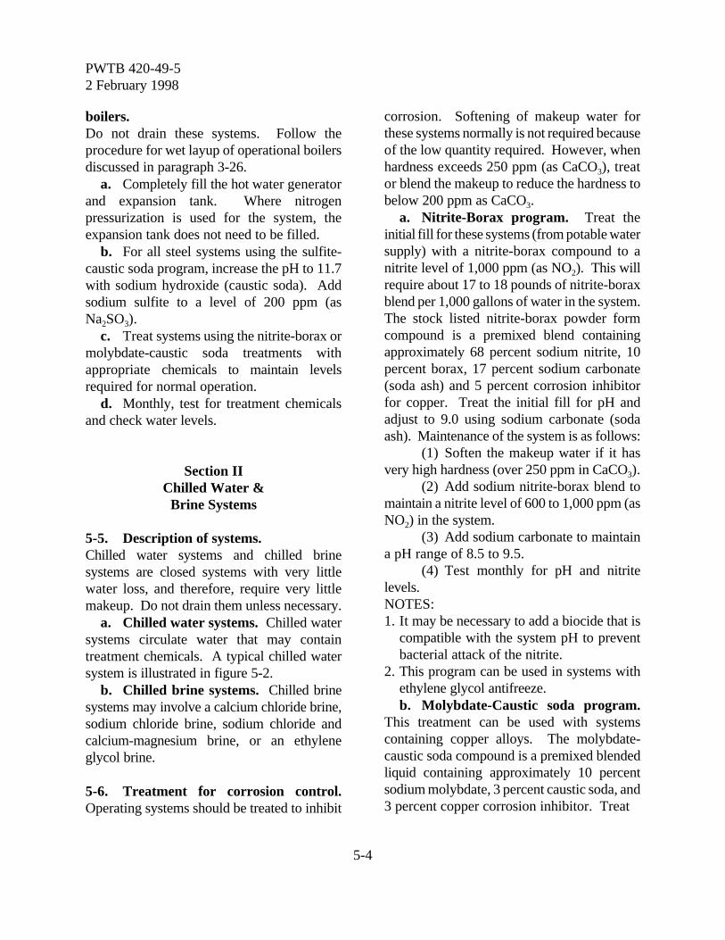
PWTB 420-49-52 February 1998
5-4
boilers. Do not drain these systems. Follow theprocedure for wet layup of operational boilersdiscussed in paragraph 3-26.
a. Completely fill the hot water generatorand expansion tank. Where nitrogenpressurization is used for the system, theexpansion tank does not need to be filled.
b. For all steel systems using the sulfite-caustic soda program, increase the pH to 11.7with sodium hydroxide (caustic soda). Addsodium sulfite to a level of 200 ppm (asNa2SO3).
c. Treat systems using the nitrite-borax ormolybdate-caustic soda treatments withappropriate chemicals to maintain levelsrequired for normal operation.
d. Monthly, test for treatment chemicalsand check water levels.
Section IIChilled Water &
Brine Systems
5-5. Description of systems. Chilled water systems and chilled brinesystems are closed systems with very littlewater loss, and therefore, require very littlemakeup. Do not drain them unless necessary.
a. Chilled water systems. Chilled watersystems circulate water that may containtreatment chemicals. A typical chilled watersystem is illustrated in figure 5-2.
b. Chilled brine systems. Chilled brinesystems may involve a calcium chloride brine,sodium chloride brine, sodium chloride andcalcium-magnesium brine, or an ethyleneglycol brine.
5-6. Treatment for corrosion control.Operating systems should be treated to inhibit
corrosion. Softening of makeup water forthese systems normally is not required becauseof the low quantity required. However, whenhardness exceeds 250 ppm (as CaCO3), treator blend the makeup to reduce the hardness tobelow 200 ppm as CaCO3.
a. Nitrite-Borax program. Treat theinitial fill for these systems (from potable watersupply) with a nitrite-borax compound to anitrite level of 1,000 ppm (as NO2). This willrequire about 17 to 18 pounds of nitrite-boraxblend per 1,000 gallons of water in the system.The stock listed nitrite-borax powder formcompound is a premixed blend containingapproximately 68 percent sodium nitrite, 10percent borax, 17 percent sodium carbonate(soda ash) and 5 percent corrosion inhibitorfor copper. Treat the initial fill for pH andadjust to 9.0 using sodium carbonate (sodaash). Maintenance of the system is as follows:
(1) Soften the makeup water if it hasvery high hardness (over 250 ppm in CaCO3).
(2) Add sodium nitrite-borax blend tomaintain a nitrite level of 600 to 1,000 ppm (asNO2) in the system.
(3) Add sodium carbonate to maintaina pH range of 8.5 to 9.5.
(4) Test monthly for pH and nitritelevels.NOTES:1. It may be necessary to add a biocide that is
compatible with the system pH to preventbacterial attack of the nitrite.
2. This program can be used in systems withethylene glycol antifreeze.b. Molybdate-Caustic soda program.
This treatment can be used with systemscontaining copper alloys. The molybdate-caustic soda compound is a premixed blendedliquid containing approximately 10 percentsodium molybdate, 3 percent caustic soda, and3 percent copper corrosion inhibitor. Treat
PWTB 420-49-52 February 1998
5-5
FIGURE 5-2TYPICAL CHILLED WATER SYSTEM

PWTB 420-49-52 February 1998
5-6
the initial fill with the sodium molybdatecompound to a molybdate level of 125 ppm(as MoO4) and adjust the pH to 8.5 withsodium hydroxide (caustic soda).
(1) Soften the makeup water if it hasvery high hardness (over 250 ppm as CaCO3).
(2) Add the molybdate-caustic sodacompound to maintain a molybdate level of100 to 125 ppm (as MoO4).
(3) Add sodium hydroxide (causticsoda) to maintain a pH range of 8.0 to 9.0.NOTES:1. This program can be used with ethylene
glycol antifreeze.2. Test monthly for proper pH and molybdate
levels.
5-7. Determining leaks in the system. Thepresence of leaks in the system can be checkedby testing the inhibitor concentration in thecirculating fluid. Measure and record theinhibitor concentration once per month. Whenthe inhibitor concentration has dropped to 98percent of the original value, about 2 percentof the system water will have been lost. If thelapsed time for this 2 percent loss is less than4 months, the system leakage is excessive andshould be investigated and corrected.NOTE:
Two percent loss over 4 months isequivalent to 0.5 percent loss per month.However, due to the accuracy of analysis ofthese tests, it is better to use a longer timefor confirming this loss rate. If the rate forany month exceeds 1 percent, it is advisableto repeat the test and then investigate if theresults still indicate large amounts ofleakage.
Example 5-1:1. The initial molybdate concentration of
chilled water system is 125 ppm. After3 months, the concentration is 123
ppm. Is the water loss excessive?
Loss = initial - final x 100 = 125 - 123 x 100initial 125
= 1.6 % after 4 months
2. The monthly loss based on the 4 monthresult is calculated:
1.6
Monthly Loss = = 0.8% per month 4 months
This loss is less than 0.5 percent andnot excessive.
3. If the concentration had dropped to 123ppm after 2 months, the loss would be:
Loss = 125 - 123 x 100 = 1.6 percent after 2 months
125
4. The monthly loss is calculated: 1.6Monthly Loss = = 0.8% per month
2 months
This loss is greater than 0.5 percent,and the system should be inspected forleaks.
Section IIICombined Hot And Chilled
Water Systems
5-8. Description of systems. Some systems serve the dual purpose ofheating and cooling by circulating hot waterduring the cold season and chilled waterduring the hot season.
5-9. Treatment required. Keep the makeupto these systems to a minimum by controllingleaks and avoiding consumptive use. Treat themakeup with a zeolite softener when hardnessexceeds 250 ppm (as CaCO3). The nitrite-borax treatment or the molybdate-caustic sodatreatment program is recommended asdescribed in paragraphs 5-3d and e. Monthlytesting of these systems is usually adequate.

PWTB 420-49-52 February 1998
5-7
Section IVDiesel Engine Jacket
Cooling Systems
5-10. General information. Diesel enginesmay be operated continuously or they may beon a standby basis. These systems are usuallyclosed systems, except where surge tanks maybe partially open to the atmosphere. The heattransfer from the circulating water is usuallythrough a heat exchanger or similar device.These systems have very low losses, and themakeup requirements are close to zero.Chemical treatment of these systems requiresinfrequent makeup, but the variety of metals inthese systems may cause some corrosionproblems. There are three types of systems:
a. Air cooled systems. Air cooledsystems are used on small engines andsometimes on large engines. The jacket wateris circulated through a radiator that is cooledby air. Antifreeze must be used in thesesystems in freezing areas because the radiatorsare exposed to the atmosphere.
b. Water cooled systems. Water cooledsystems are used on large engines. The jacketcooling water passes through a heatexchanger, where a separate cooling watersystem removes the heat from the jacketcooling water. These systems commonly willuse antifreeze. The separate cooling watersystem may require treatment.
c. Vapor-Phase cooling systems (alsocalled ebullient systems). Vapor-phasecooling systems operate by heating the waterto boiling temperature (or greater, for pressuresystems). Steam is formed from the water,which removes heat from the system. Thesteam often is used for space heating as amethod for recovery and reuse of waste heat.This type of system will require makeup ofboth water and treatment chemicals.
5-11. Treatment required. Normally, diesel engine cooling systemsrequire little makeup. Since scale formationmust be prevented, softening of makeup wateris recommended when the hardness exceeds 50ppm (as CaCO3). Demineralization may berequired where saline water (such as seawater)is used.
a. Corrosion control in continuouslyoperated systems. Special corrosion controlmay not be required for small systems wheremakeup water is rarely required and aninhibited antifreeze is used. Adjust themakeup for these small systems with sodiumcarbonate (soda ash) to maintain the pH in thesystem between 7.5 and 8.5. Large,continuously operated diesel engines may alsouse an inhibited antifreeze. If necessary, theycan be treated and controlled with the sodiumnitrite-borax treatment program (paragraph 5-3d) or the molybdate-caustic soda treatmentprogram (paragraph 5-3e). If operatingsystems are not treated and monitored, replacethe antifreeze every year.
b. Corrosion control in standby units.Normally, those systems that use an inhibitedantifreeze will not require additional treatment.If necessary, the sodium nitrite-boraxtreatment or the molybdate-caustic sodatreatment program can also be used foradditional corrosion control.
c. Systems without antifreeze. Treatsystems (operating or standby) that do not usean inhibited antifreeze with a nitrite-boraxprogram or a molybdate-caustic soda program.
d. Testing required. Monthly testing tomonitor pH and nitrite or molybdate levels isusually adequate.

PWTB 420-49-52 February 1998
6-1
Chapter 6
Sampling And Testing Of Industrial Water Systems
Section IGeneral Information
6-1. Requirement for sampling andtesting:
a. Purpose of sampling and testing.Regular, representative sampling and accuratetesting are essential parts of a sound industrialwater treatment program. Each treatedindustrial water system must be tested often toshow whether the proper chemical levels arebeing maintained and whether the pH of thewater is within the set range. Sampling andtesting frequencies outlined in this chapter willensure an effective industrial water treatmentprogram. Safety considerations must be apriority when sampling any industrial watersystem and when conducting laboratory tests.
b. Quality assurance sample analysis.Sampling requirements for the qualityassurance program described in paragraph 1-8are as follows:
(1) Each operating boiler plantequipped with hot water or steam boilers withone or more boilers of 3.5 MBTU/hr or 100horsepower or greater capacity must submit asample for quality assurance each month.
(2) Each operating boiler plantequipped with hot water or steam boilers ofless than 3.5 MBTU/hr or 100 horsepowercapacity shall submit a sample for qualityassurance once every three months.
(3) Sample size will be 32-ounce, or asrequired by the contract laboratory, for all highpressure (15 psig or greater) boilers and lowpressure boilers treated with caustic,phosphate, tannin, and sodium sulfite.
(4) Sample size will be 4-ounce for lowpressure boilers (less than 15 psig) treated
with caustic only.(5) Sample size will be 32-ounce, or as
required by the contract laboratory, for hotwater boilers.
(6) Sample shipping containers andbottles for submission of boiler water forcheck analyses are obtained by direct requestto the contract laboratory. In overseas areaswhen the command has established a centrallaboratory for the analysis of boiler water,sample containers and bottles should beobtained from that source. Containers forhigh-pressure boiler water samples aredesigned for shipping a 32-ounce plasticbottle. Containers for water samples fromlow-pressure boilers treated with caustic sodaare designed for shipping a 4-ounce plasticbottle. Pack the bottle carefully so that it willnot leak in shipment. A data sheet is enclosedin each sample container. Completely fill outthe data sheet and ship it with the sample.
6-2. In-plant testing. Army installations arerequired to obtain test chemicals andequipment from commercial sources, usuallyas test kits. Test procedures will be furnishedwith the test kits.
Section IISampling And Testing Cooling
Towers
6-3. Methods of sampling. Collect coolingtower water samples in clean glass or plasticbottles, cap immediately, and test withoutdelay. Do not take the sample immediatelyafter treatment chemicals are added, but whenthe chemicals have mixed with the systemwater. Samples of the recirculating water can
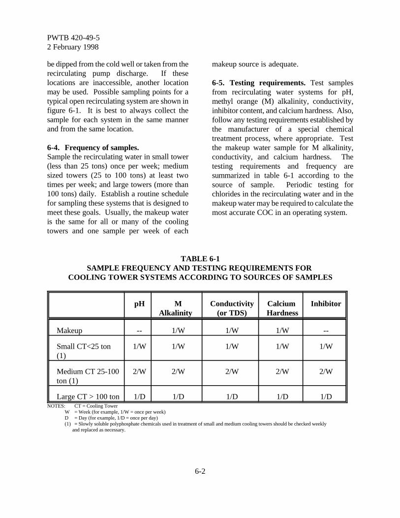
PWTB 420-49-52 February 1998
6-2
be dipped from the cold well or taken from therecirculating pump discharge. If theselocations are inaccessible, another locationmay be used. Possible sampling points for atypical open recirculating system are shown infigure 6-1. It is best to always collect thesample for each system in the same mannerand from the same location.
6-4. Frequency of samples.Sample the recirculating water in small tower(less than 25 tons) once per week; mediumsized towers (25 to 100 tons) at least twotimes per week; and large towers (more than100 tons) daily. Establish a routine schedulefor sampling these systems that is designed tomeet these goals. Usually, the makeup wateris the same for all or many of the coolingtowers and one sample per week of each
makeup source is adequate.
6-5. Testing requirements. Test samplesfrom recirculating water systems for pH,methyl orange (M) alkalinity, conductivity,inhibitor content, and calcium hardness. Also,follow any testing requirements established bythe manufacturer of a special chemicaltreatment process, where appropriate. Testthe makeup water sample for M alkalinity,conductivity, and calcium hardness. Thetesting requirements and frequency aresummarized in table 6-1 according to thesource of sample. Periodic testing forchlorides in the recirculating water and in themakeup water may be required to calculate themost accurate COC in an operating system.
TABLE 6-1SAMPLE FREQUENCY AND TESTING REQUIREMENTS FOR
COOLING TOWER SYSTEMS ACCORDING TO SOURCES OF SAMPLES
pH MAlkalinity
Conductivity(or TDS)
Calcium Hardness
Inhibitor
Makeup -- 1/W 1/W 1/W --
Small CT<25 ton(1)
1/W 1/W 1/W 1/W 1/W
Medium CT 25-100ton (1)
2/W 2/W 2/W 2/W 2/W
Large CT > 100 ton 1/D 1/D 1/D 1/D 1/DNOTES: CT = Cooling Tower
W = Week (for example, 1/W = once per week)D = Day (for example, 1/D = once per day)(1) = Slowly soluble polyphosphate chemicals used in treatment of small and medium cooling towers should be checked weekly
and replaced as necessary.
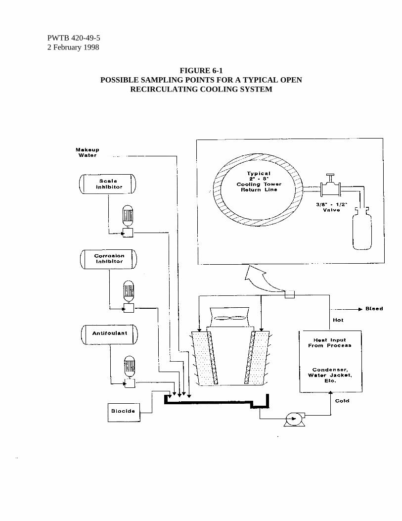
PWTB 420-49-52 February 1998
6-3
FIGURE 6-1POSSIBLE SAMPLING POINTS FOR A TYPICAL OPEN
RECIRCULATING COOLING SYSTEM
PWTB 420-49-52 February 1998
6-4
Section IIISampling & Testing Boilers
6-6. Method of sampling. Boiler water willbe hot and under pressure. If the water is notcooled as it is sampled, part of the water willflash off as steam and the remaining samplewill not be representative of the system. Theresulting sample will show lower oxygen andcarbon dioxide readings than actual levels inthe boiler. Other values will generally behigher because of less water in the test samplefor the same amount of solids. Use of asample cooler described below will greatlyreduce the chance of the operator gettingburned, and the possibility of obtaining anonrepresentative sample.
a. Sampling cooler. Use a commerciallyavailable sample cooler when collecting asample. If not available, then use a 15 to 20foot coil of copper or stainless steel tubing tocool the sample. The coil can be immersed ina permanent cooling jacket as shown in figure6-2, or it may be immersed in a bucket of coldwater; when this does not interfere withoperation of the system or create a hazard.The flow of the sample through the coil mustbe slow enough so that the cooled sample isnot more than just warm to the hand(approximately 100oF).
b. Sampling procedures. Turn on thecooling water to the cooling coil before takingthe boiler water sample and turn it off after thesample is collected. Flush the coil with severaltimes its volume before taking the sample.Then extend the end of the sample coil to thebottom of the sample bottle and allow at leastone volume of the bottle to overflow from thecontainer during the collection process. Thebottle can be glass, but plastic bottles arepreferred. Do not use glass bottles if the
boiler is silica limited, or if high silica issuspected.
c. Sampling locations. See figure 6-3 fortypical locations for water sampling points ina steam boiler system. Each sampling pointshould have a separate cooling coil. Two ormore sampling points manifolded to the samecooling coil is not a desirable situation becauseit is almost impossible to know if one of thevalves has a leak that might contaminate thesample being taken.
(1) The makeup water sample does nothave to be cooled. The sample locationtypically will be the output of an ion exchangeunit or some other water softening unit.
(2) The boiler feedwater sample is acombination of makeup and condensate return.Take the sample from the discharge of theboiler feed pump. It may be a hot sample.
(3) The boiler water will be very hot.It is best to take this sample from thecontinuous blowdown line between the boilerand the regulating valve. It can be taken froma gauge-glass connection, if necessary.
(4) The steam condensate will be hot.For small systems, take the sample from a linethat enters the deaerating heater if possible.Also, for medium and large systems, it may benecessary to take condensate samples at twoor more locations in the system to calculate theproper treatment level. It is sometimesnecessary to take condensate samples fromvarious locations in the system whenattempting to find a leak.
(5) Steam samples are rarely taken.For sampling methods see the AmericanSociety of Mechanical Engineers (ASME)Performance Test Code.6-7. Frequency of samples and testing. Thesample and testing frequency for steam boilersystems is summarized in table 6-2.

PWTB 420-49-52 February 1998
6-5
FIGURE 6-2DIAGRAM OF A BOILER OR CONDENSATE SAMPLE COOLING COIL
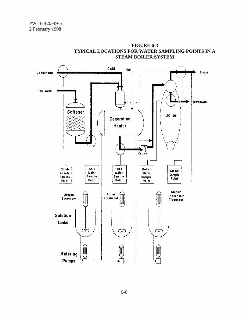
PWTB 420-49-52 February 1998
6-6
FIGURE 6-3TYPICAL LOCATIONS FOR WATER SAMPLING POINTS IN A
STEAM BOILER SYSTEM
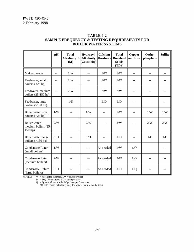
PWTB 420-49-52 February 1998
6-7
TABLE 6-2SAMPLE FREQUENCY & TESTING REQUIREMENTS FOR
BOILER WATER SYSTEMS
pH Total Alkalinity (1)
(M)
Hydroxyl Alkalinity
(Causticity)
CalciumHardness
TotalDissolved
Solids(TDS)
Copperand Iron
Ortho-phosphate
Sulfite
Makeup water -- 1/W -- 1/W 1/W -- -- --
Feedwater, smallboilers (<25 hp)
-- 1/W -- 1/W 1/W -- -- --
Feedwater, mediumboilers (25-150 hp)
-- 2/W -- 2/W 2/W -- -- --
Feedwater, largeboilers (>150 hp)
-- 1/D -- 1/D 1/D -- -- --
Boiler water, smallboilers (<25 hp)
1/W -- 1/W -- 1/W -- 1/W 1/W
Boiler water,medium boilers (25-150 hp)
2/W -- 2/W -- 2/W -- 2/W 2/W
Boiler water, largeboilers (>150 hp)
1/D -- 1/D -- 1/D -- 1/D 1/D
Condensate Return(small boilers)
1/W -- -- As needed 1/W 1/Q -- --
Condensate Return(medium boilers)
2/W -- -- As needed 2/W 1/Q -- --
Condensate Return(large boilers)
1/D -- -- As needed 1/D 1/Q -- --
NOTES: W = Week (for example, 1/W = once per week)D = Day (for example, 1/D = once per day)Q = Quarter (for example, 1/Q - once per 3 months)
(1) = Feedwater alkalinity only for boilers that use dealkalizers
PWTB 420-49-52 February 1998
6-8
a. Feedwater sample. Take feedwatersamples once a week for small boilers (lessthan 25 hp); at least two times per week formedium boilers (25 to 150 hp); and daily forlarge boilers (more than 150 hp). Test thesamples for M alkalinity, conductivity, andcalcium hardness.
b. Condensate sample. Take condensatesamples once a week for small boilers (lessthan 25 hp); at least two times a week formedium boilers (25 to 150 hp); and daily forlarge boilers (more than 150 hp). Test for pHand conductivity. If the conductivity is greaterthan 35 micromhos, test for calcium hardness.Test the condensate for iron and copper, ifapplicable, on a quarterly basis.
c. Blowdown sample. Take blowdownsamples for small boilers (less than 25 hp)once per week; for medium boilers (25 to 150hp) at least two times per week; and for largeboilers (more than 150 hp) daily. Test forhydroxyl (OH) alkalinity (causticity),neutralized conductivity, orthophosphate, andsulfite.
Section IVSampling And Testing Other
Water Systems
6-8. Hot and chilled circulating water. Thetesting frequency for these systems issummarized in table 6-3 with additionalinformation provided below.
a. Makeup water to hot water boilers,chilled water circulation systems, and dieselengine jackets usually comes from an ionexchange unit or a dealkalizer (see paragraph6-9).
b. Test recirculating water from HTWsystems and systems using the sulfite-causticsoda treatment program (paragraph 5-3c) onceper day for pH and sulfite.
c. Test recirculating chilled and hot watertreated with the nitrite-borax or molybdate
programs (paragraphs 5-3d and e) once permonth for either molybdate or nitritedepending upon the chemical in use. Also testthe system pH once per month and afterchemical addition.
6-9. Ion exchangers and dealkalizers. Thetesting frequency for these systems issummarized in table 6-3 with additionalinformation provided below.
a. Test ion exchange influent water onceper week for total hardness. Test dealkalizerinfluent water once per week for total (M)alkalinity.
b. Test the effluent water from thesesystems for total hardness either once per dayor once per shift (three times a day) dependingon the frequency of regeneration. Cycle lengthwill depend upon feedwater hardness, bed size,resin type, strength of regenerant, and flowrate.
c. The location of the sample point isimportant to ensure that the proper sample isobtained. Care must be taken to avoidcollecting a sample that is a mixture of influentand effluent water on ion exchange units thatuse automatic regeneration and multiportvalves.
d. The operator must mix the brine used forregeneration. In some cases, the brine shouldbe sampled and tested with a hydrometer tomeasure its strength. The brine should be asnear 100 percent saturation as possible(approximately 28%).
Section VTesting Procedures
6-10. Purpose of testing. Water testing isperformed to provide the proper control ofrecommended treatments. Testing is not onlyfor the purpose of record keeping, althoughgood records will aid in the analysis of long-term effectiveness of treatment methods. Test
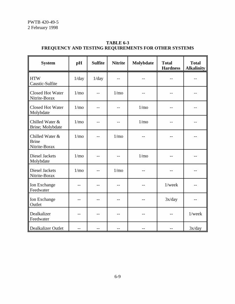
PWTB 420-49-52 February 1998
6-9
TABLE 6-3FREQUENCY AND TESTING REQUIREMENTS FOR OTHER SYSTEMS
System pH Sulfite Nitrite Molybdate TotalHardness
TotalAlkalinity
HTWCaustic-Sulfite
1/day 1/day -- -- -- --
Closed Hot WaterNitrite-Borax
1/mo -- 1/mo -- -- --
Closed Hot WaterMolybdate
1/mo -- -- 1/mo -- --
Chilled Water &Brine; Molybdate
1/mo -- -- 1/mo -- --
Chilled Water &BrineNitrite-Borax
1/mo -- 1/mo -- -- --
Diesel JacketsMolybdate
1/mo -- -- 1/mo -- --
Diesel JacketsNitrite-Borax
1/mo -- 1/mo -- -- --
Ion ExchangeFeedwater
-- -- -- -- 1/week --
Ion ExchangeOutlet
-- -- -- -- 3x/day --
DealkalizerFeedwater
-- -- -- -- -- 1/week
Dealkalizer Outlet -- -- -- -- -- 3x/day
PWTB 420-49-52 February 1998
6-10
results that do not agree with the resultsexpected for the treatment method being usedshould be acted upon immediately. This caninvolve reanalysis and checking of the testreagents. If the test results are correct, thetreatment program should be evaluated.Section VI discusses interpretation of testresults.
6-11. Water sample testing procedures.Water test procedures will be provided withthe test kits obtained from commercialsources. Test kit requirements will generallyinclude tests for:
a. Alkalinity-Phenolphthalein (P); Alkalinity-Methyl Orange (M) or Total;Alkalinity-Hydroxyl (OH) or Causticity
b. Conductivityc. Tannind. pHe. Hardness (total, calcium, magnesium)f. Phosphate (orthophosphate, total
phosphate)g. Sulfiteh. Nitritei. Chloridej. Molybdate
6-12. Corrosion testing. A positive way todetermine if corrosion is occurring is to placecorrosion test specimens in the system. Armyinstallations are strongly encouraged to test forpossible corrosion in large or critical heatingand cooling systems.
a. There are two corrosion test specimenscommonly used. These are listed below.
(1) Corrosion test coupons for use inopen and closed cooling systems, closed hotwater systems, and domestic water systems(refer to appendix C).
(2) Corrosion pipe inserts for use insteam condensate return systems (refer toappendix D). The inserts are captive in anassembly of 3/4" pipe.
b. Corrosion test coupons and analysis ofexposed coupons are available from a numberof commercial sources. Pipe insert assembliesfor steam condensate systems and analyticalevaluation of the test inserts are available fromthe quality assurance laboratory under contractwith USACPW. Guidance covering corrosiontesting is provided in appendices C and D.
c. Corrosion test results are usuallyreported as a rate of corrosion penetration intothe metal given in mils penetration per year(mpy). A mil is one-thousandth (0.001) inch.Thus, the corrosion rate of 10 mpy means thatthe thickness of a piece of metal is reduced by10 x 0.001 = 0.01 inches per year. If the metalbeing studied is 1/16 or 0.0625 inches thick,this means that it will be completely destroyedin just over 6 years. Corrosion rates may alsobe expressed in millimeters per year (mmpy)penetration. The relationship between mpyand mmpy is: 1 mpy = 0.0254 mmpy; 1 mmpy= 39.4 mpy.
d. Corrosion also may be given as a weightloss in milligrams per square decimeter per day(mdd). For steel, the relationship betweenpenetration and weight loss is: 1 mdd = 0.2mpy or 1 mpy = 5 mdd.
e. There are a variety of electricalinstruments available which monitor andrecord corrosion rates. These are installed andmaintained by specialists.
Section VIInterpretation Of Tests
6-13. General information. Many watertreatment systems require that a specific levelof a treatment chemical be carried in the water.This applies to nitrites, phosphates, sulfites,molybdates, and to any specialized chemicalsused in the treatment program. When a testindicates that a chemical is not within the limitsrequired for the treatment program, confirm

PWTB 420-49-52 February 1998
6-11
that the test was performed properly and isvalid. (Check test methods, including thechemical reagents, on a routine basis evenwhen treatment levels are being maintained.)
a. When the valid test results indicate alevel that is too low, evaluate the chemicaladdition program and make the appropriateadjustment. This normally means increasingthe chemical feed rate by 10 percent or less. Ifadjustments to the treatment program do notcorrect the situation, then evaluate the systemin total to determine the nature of the problem.Outside assistance can be obtained through theUSACPW (CECPW-ES).
b. When the valid test results indicate alevel that is too high, evaluate the chemicaladdition program. Care should be used inreducing chemical feed rates based on a levelthat is too high. Do not reduce the chemicalfeed rate more than 5 to 10 percent at any onetime.
c. When the test for hardness indicateslevels in the system that are higher than thedesired level, investigate the makeup treatmentsystem for problems. Also investigate otherpossible sources of hardness in the system.
6-14. Alkalinity relationships:a. Sources of alkalinity. The three basic
sources of alkalinity in water are: alkalinityresulting from the bicarbonate ion (HCO3
-), thecarbonate ion (CO3
=), and the hydroxyl ion(OH-). The amount of each of these in watercan be determined by titrating with an acid tocertain pH levels (end points) usingphenolphthalein (P alkalinity) and a methylorange (M alkalinity) end points. Therelationship between pH and these alkalinitiesis shown in figure 6-4.
b. Relationship of P, M and OHalkalinities. Test procedures for determiningthe P and M alkalinities are included incommercially available test kits. The OHalkalinity can be determined by a specific test
or it can be calculated from the P and Malkalinities. The OH alkalinity is the result ofthe hydroxyl ion (OH-) in the water, and is alsoknown as "caustic alkalinity" or "causticity".The relationship between the measured P andM alkalinities and level of hydroxyl, carbonate,and bicarbonate forms of the alkalinity isshown in table 6-4 and is discussed below.
Example 6-1:P = 86 ppm, M = 118 ppm; situation 2exists (P > 1/2M);Hydroxyl = 2 x 86 - 118
= 54 ppmCausticity = hydroxyl alkalinity ÷3
= 54÷3 = 18 ppmCarbonate = 2 x (118 - 86)
= 64 ppmBicarbonate = 0 ppmCheck: Total = 54 + 64 + 0 = 118 ppm
(1) The tests for P alkalinity and Malkalinity may give the same result. Thismeans that all of the alkalinity is due tohydroxyl ions. There is no carbonate orbicarbonate present. (This is rare, but occurswhen a caustic solution unexposed to air).
(2) The P alkalinity may be greaterthan one-half of the M alkalinity. Thisindicates that there is hydroxyl and carbonatealkalinity, but no bicarbonate alkalinity.
(3) The P alkalinity may be equal toone-half of the M alkalinity. This indicatesthat all the alkalinity is due to carbonate.There is no bicarbonate alkalinity, and thehydroxyl alkalinity is insignificant.
(4) The P alkalinity is less than one-half of the M alkalinity. This indicates thatcarbonates and bicarbonates are present.
(5) The P alkalinity is zero. The Malkalinity is due to bicarbonates only.
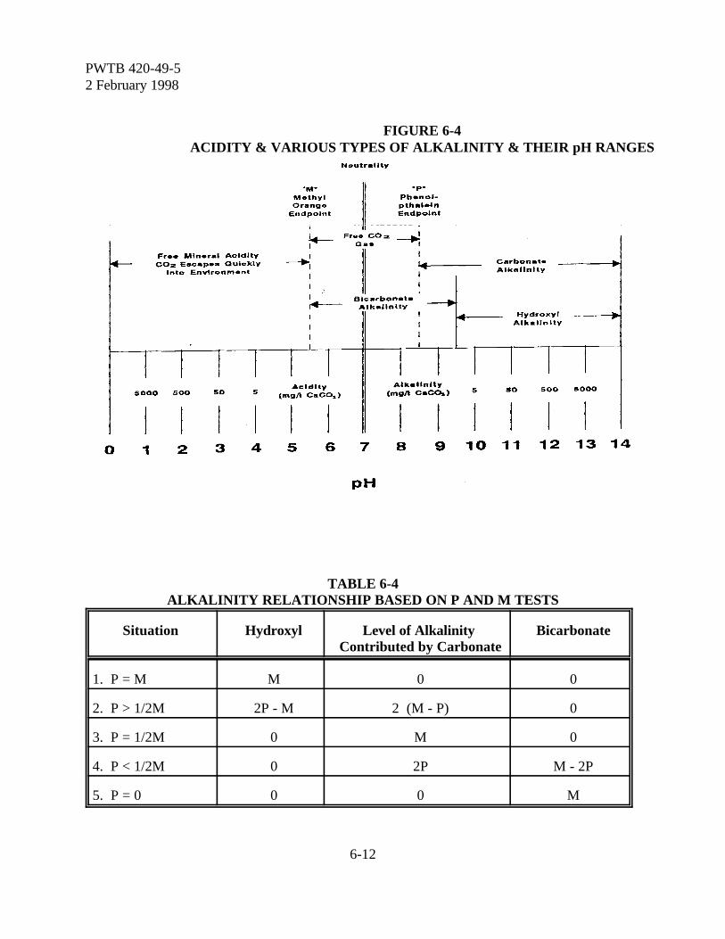
PWTB 420-49-52 February 1998
6-12
FIGURE 6-4ACIDITY & VARIOUS TYPES OF ALKALINITY & THEIR pH RANGES
TABLE 6-4ALKALINITY RELATIONSHIP BASED ON P AND M TESTS
Situation Hydroxyl Level of Alkalinity Contributed by Carbonate
Bicarbonate
1. P = M M 0 0
2. P > 1/2M 2P - M 2 (M - P) 0
3. P = 1/2M 0 M 0
4. P < 1/2M 0 2P M - 2P
5. P = 0 0 0 M

PWTB 420-49-52 February 1998
6-13
6-15. Hydrogen ion concentration (pH):a. Meaning of pH.
The pH is a measure of the acidity or alkalinityof the water. (The test specifically measuresthe concentration of hydrogen ion in thewater). A neutral water will have a pH of 7.Values less than 7 are considered acidic.Values greater than 7 are considered alkaline.
(1) Common pH values for materialson the acid side include spinach with a pH ofabout 5.5, orange juice, and most soft drinkswith a pH of about 3.5, lemon juice with a pHof about 2.2, and 0.1 N sulfuric acid with a pHof 1.2.
(2) Common pH values of materials onthe alkaline side include sodium bicarbonatewith a pH of about 8.4, milk of magnesia witha pH of about 10.5, household ammonia witha pH of about 11.5, and 0.1 N sodiumhydroxide with a pH of 13.0.
(3) The pH scale is logarithmic. A pHof 4 is 10 times as acidic as a pH of 5 and ahundred times as acidic as a pH of 6. This isimportant to consider when adding a strongacid to a system, because 0.1 N sulfuric acidwill have more than 100,000 times the acidityof neutral water.
b. Relationship to causticity. When thepH of a water exceeds about 9.6 to 9.8, ameasurable concentration of hydroxyl ions(OH-) begins to appear. As the hydroxylalkalinity (causticity) increases, the pH of thesolutions also increases. The relationshipbetween causticity and pH is shown in table6-5.
6-16. Conductivity and total dissolvedsolids. In neutral or alkaline waters, there is noconsistent relationship between conductivityand TDS. If alkaline water is acidized to thephenolphthalein end point with an organic acidsuch as gallic acid (which neutralizes causticitybut does not contribute conductivity), the TDS
is approximately equal to two-thirds theneutralized conductivity in micromhos. AtArmy installations, a factor of 0.7 will be usedfor water treated with synthetic polymers as asludge dispersant, and from 0.7 to 1.0 forwater treated with Quebracho tannin,depending on the amount of tannin in thewater. Conductivity and TDS are used todetermine the COC and the potential for scaleformation (chapter 3).
Section VIIIn-plant Laboratory
Requirements
6-17. General data. Provide the wateranalyst with a separate laboratory space toperform the routine control tests that arerequired. The space preferably should be setoff from the industrial plant by walls. Includea suitable bench, sink and cabinet, a distilled ordeionized water source, and have ventilationand comfort heating and cooling. Providestandard lighting at reading intensity withwhite fluorescent lamps. A record file for testresults and references should be located in thelaboratory.
6-18. Laboratory equipment recommended. Select the equipment at eachlocation to perform all of the tests routinelyperformed. Provide sufficient quantities ofstandard materials such as beakers, test tubes,graduated cylinders, and casseroles so that thetests can be performed efficiently. Theequipment required for each test will beincluded with the appropriate test kit.
6-19. Chemical reagents. Maintain a masterlist of reagents that are stocked, their referencenumber, the quantity of stock, and the test forwhich the reagent is used. The minimum stocklevel should be defined, and the reagent
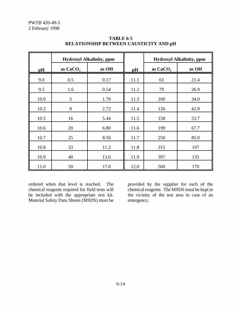
PWTB 420-49-52 February 1998
6-14
TABLE 6-5RELATIONSHIP BETWEEN CAUSTICITY AND pH
pH
Hydroxyl Alkalinity, ppm
pH
Hydroxyl Alkalinity, ppm
as CaCO3 as OH as CaCO3 as OH
9.0 0.5 0.17 11.1 63 21.4
9.5 1.6 0.54 11.2 79 26.9
10.0 5 1.70 11.3 100 34.0
10.2 8 2.72 11.4 126 42.8
10.5 16 5.44 11.5 158 53.7
10.6 20 6.80 11.6 199 67.7
10.7 25 8.50 11.7 250 85.0
10.8 33 11.2 11.8 315 107
10.9 40 13.6 11.9 397 135
11.0 50 17.0 12.0 500 170
ordered when that level is reached. Thechemical reagents required for field tests willbe included with the appropriate test kit.Material Safety Data Sheets (MSDS) must be
provided by the supplier for each of thechemical reagents. The MSDS must be kept inthe vicinity of the test area in case of anemergency.

PWTB 420-49-52 February 1998
7-1
Chapter 7
Chemical Mixing, Feeding, And Control Devices
Section IGeneral Information
7-1. Chemical mixing. The mixing ofchemicals is necessary when dissolving drychemicals or when reducing the concentrationof liquid chemicals.
a. Liquid chemicals. A liquid chemicalcan be adjusted to a lower concentration byadding water. This should be done with carefor acids and alkalis. The concentration ofpurchased chemicals may need to be reducedwhen only a small quantity of chemical is to befed. Better control of the treatment programis possible by feeding a lower concentrationchemical at a higher and easier to control flowrate.
b. Dry chemicals. Dry chemicalsfrequently must be added as a solution to thewater system. Dry chemicals are dissolved inwater to make a known concentration of thechemical. Specific instructions on mixing adry chemical are normally provided with thechemical.
c. Chemical mixture. A chemicalmixture can be procured (such as nitrite-borax)or developed at the installation for a specificapplication to reduce the effort required to addseveral chemicals to a water system. Themixture can be developed using either liquid ordry chemicals, or by supplementing an existingmixture with a specific chemical. Thechemicals in a mixture must be at the properproportions to match the treatment needs ofthe system. The chemicals also must becompatible, not react in the mixture and notcome back out of solution.7-2. Chemical feeding. Feed chemicals to
the water treatment system on the basis of thetreatment program requirements and theresults of the test program.
a. Feed options. If the test programresults indicate that the chemical residuallevels are either too low or too high, increaseor decrease the addition of the treatmentchemical. The options for changing a feedprogram are listed below. The selection ofone option depends on the type of feedequipment.
(1) The rate at which the chemicalsolution is fed to the system can be changed tobe either higher or lower.
(2) The concentration of thechemical in the feed stream can be increasedby adding the concentrated chemical to themixing tanks, or decreased by diluting thechemical with water in the mixing tanks.
(3) The frequency or quantity ofchemicals added on an intermittent basis maybe changed.
b. Feed methods. The method ofchemical feed is dependent upon the type ofwater treatment system and the reasons foradding the chemical. The common methods offeeding are described below:
(1) Continuous feed systems involvethe addition of chemicals at a constant rate.This rate may be a constant flow of materialsinto the water system, or the rate may beautomatically adjusted according to a systemparameter such as pH or flow rate.
(2) Intermittent feed systems may beoperated either manually, or they may beautomatically operated on a timer basis, orthey may be based on a system parameter suchas blowdown.
PWTB 420-49-52 February 1998
7-2
(3) Slug feed systems involve theaddition of chemicals in excess of the amountrequired to just meet the level required in thesystem. The timing and quantity of a slug feedis adjusted in order to always maintain a levelof at least the minimum required in the watersystem.
(4) Shock feed is a special chemicalfeed method used for microbiological controlin cooling water systems. A high level ofchemical is added on an infrequent basis inorder to shock the system and provide thenecessary "kill" effect.
7-3. Chemical control. The control ofchemical levels in treated water systemsgenerally involves one of three methods.
a. Continuous testing. Continuoustesting can be used in large systems where theservice requirement justifies continuouscontrol or the cost of the chemical feedwarrants close control. This techniquerequires monitoring devices external to thesystem with probes and transmitters sending asignal to the monitoring device. Thesesystems often are linked directly to thechemical feed system to provide automaticcontrol of the chemical feed.
b. Manual testing. Manual testing ismost common. This technique is effectivewhere the treatment chemical levels in thesystem are not expected to vary widely inshort periods of time, or the treatmentchemical feed can be linked to the makeupwater flow rate. Normally, the results of themanual testing are used to manually adjust thechemical feed rates.
c. No testing. No testing is used onlywhere there is a chemical feed system that isnot controlled from day to day, or there is notreatment. This technique is used, forexample, at remote cooling towers where aslowly soluble chemical is suspended in the
cold well. Even for such systems, anoccasional test for treatment chemical level isrecommended.
Section IIChemical Mixing Procedures
7-4. Dissolving dry chemicals.Fill the chemical vat about one-half full ofsoftened water (or condensate). Turn on themixer and add the chemical slowly into thevortex of the mixing action. After a fewminutes, fill the vat with softened water to theproper level and continue mixing for 10 to 15minutes.
a. Improper location of the mixer shaftmay cause difficulties in dissolving chemicals.Locate the shaft on one side of the tank andslanted into the water. The contents of the vatshould move in a circular pattern.
b. Solutions greater than about 5 percentconcentration may be difficult to attain forsome chemicals. Review the guidanceprovided in chemical data sheets for eachchemical to determine any special mixingproblems.
c. The amount of chemical to add can bedetermined from the desired concentration andthe volume of the vat. The concentration of asolution can be calculated from the amount ofchemical added and the volume of the vat.
Example 7-1:1. A s o l u t i o n o f s o d i u m
hexametaphosphate is to have a 5percent phosphate (PO4). This is to beadded to a boiler at a rate of 3.95pounds per day of phosphate to replaceblowdown (example 3-10). The mixingvat volume is 1,000 gallons.
2. The total pounds of phosphate to addto the vat is calculated:

PWTB 420-49-52 February 1998
7-3
Phosphate, lb = Percent/100 x Vat Volume, gal x 8.33 lb/gal = (5 ÷ 100) x 1000 x 8.33 = 417 lb
3. Sodium hexametaphosphate contains90.5 percent phosphate (table 3-8).The total pounds of sodiumhexametaphosphate to add to the vat iscalculated:
Sodium hexametaphosphate, lb = Phosphate, lb ÷ Percent/100
= 417 ÷ 0.905 = 461 lb
4. Note the chemical feed rate of the 5percent phosphate solution must be3.95 lb/day of phosphate (PO4). Thegallon per day feed is calculated:
Feed, = Phosphate,÷ (8.33 lb/gal x Percent /100) gal/day lb/day Phosphate
= 3.95 ÷ (8.33 x 0.05)= 9.5 gal/day
5. The vat will need to be replenished inabout 105 calendar days (1,000 gallon÷ 9.5 gal/day).
Example 7-2:1. Boiler treatment program requires 3.95
pounds/day of phosphate (example 3-10). It is desired to establish a 60 daysupply of the mixed chemical. Therequired amount of phosphate iscalculated:
Phosphate, lb = Supply, day x Phosphate, lb/day= 60 x 3.95 = 237 lb
2. Sodium hexametaphosphate is availablein 100 pound bags at a concentration of90.5 percent phosphate (PO4).Therefore, three bags are to be added tothe vat. The amount of phosphateadded in the three bags is calculated:
Phosphate, lb = Bags x Pounds/Bag x Percent Phosphate/100 = 3 x 100 x 0.905 = 272 lb
3. The vat is 1,000 gallons. Theconcentration of phosphate in the vat iscalculated:
Concentration, percent = (100 x phosphate, lb) ÷ (8.33 lb/galx Volume, gal)
= (100 x 272) ÷ (8.33 x 1,000)= 3.3 percent
7-5. Diluting liquid chemicals.Dilute a liquid chemical to a lowerconcentration by adding softened water. Addthe concentrated chemical to a partially filledvat, and then bring the vat to a full level withmore softened water. Turn on the mixerbefore adding the chemical. Careful mixing isrequired when a volatile chemical is beingdiluted, such as the amines used forcondensate corrosion control in steam boilers.The calculations for mixing liquid chemicalsare similar to the mixing of dry chemicalsexcept that volumes are used.
7-6. Changing concentration in a tank. Itis common to add the dry or liquid chemical toa tank that is not completely empty. It alsomay be desired to adjust the concentration ofthe chemical to meet different treatmentobjectives or to make the addition of chemicalseasier to control.
a. It is convenient to express the chemicalin the tank in terms of pounds per inch (lb/in).This can be calculated by dividing the totalamount of chemical by the liquid depth of thefull tank.
b. The total amount of chemical required inthe full tank, minus the chemical remaining inthe partially filled tank, equals the amount ofchemical to add to the system. The amount ofchemical remaining in the tank is computed bymultiplying the level in the partially full tanktimes the chemical per inch.
PWTB 420-49-52 February 1998
7-4
Example 7-3:1. The chemical vat in example 7-2 has a
diameter of 6 feet and a full depth of 56inches, for a full volume of 1,000gallons. The 3.3 percent phosphate inthe full tank represented 272 pounds ofphosphate, based on three 100 poundbags of sodium hexametaphosphate.The phosphate per inch is calculated:
Phosphate, lb/in = Phosphate, lb ÷ Full Level, inches= 272 ÷ 56 = 4.9 lb/in
The level in the tank is 20 inches. Theamount of phosphate remaining in thetank is calculated:
Phosphate, lb = Level, inch x Phosphate, lb/in= 20 x 4.9 = 98 lb
2. The desired concentration in the fulltank is 2.0 percent. The total phosphaterequired in the full tank is calculated:
Phosphate = Percent/100 x Vat Volume, gal x 8.33 lb/gal= 0.02 x 1000 x 8.33 = 167 lb
3. Phosphate to add to the vat is 69pounds (167 - 98). The sodium hex-ametaphosphate contains 90.5 percentphosphate. The chemical to add iscalculated:
Chemical, lb = Phosphate, lb ÷ Percent/100= 69 ÷ 0.905 = 76 lb
4. The chemical comes in 100 pound bags,so the actual phosphate added is 91pounds (100 lb x 0.905 lb PO4/lb). Thetotal phosphate in the full tank is 189pounds (98 + 91). The new phosphateper inch is calculated:
Phosphate, lb/in = Phosphate, lb ÷ Full Level, inches= 189 ÷ 56 = 3.4 lb/in
5. The actual concentration of phosphatein the tank is calculated:
Concentration, =(100 x Phosphate, lb) ÷ (8.33 lb/gal x percent Volume, gal)
= (100 x 189) ÷ (8.33 x 1,000)= 2.27 percent
Section IIIFeeding Devices
7-7. Metering pumps:a. Feed pumps tied to pulsing makeup
meters, or some other type of proportionalfeed system are recommended for mostsystems, especially large steam and coolingwater systems and unmanned small systems.Also, if these systems have a metering pumpinstead of a proportional system, the meteringpump can be set to a short stroke or speed tofeed smaller amounts of chemical over a longperiod of time. This avoids large upswingsand downswings in system chemical levels.
b. Pumps of various types can take suctionfrom chemical solution tanks and inject asolution of a chemical into a line, a boilerdrum, or a cooling tower basin. Pump typesinclude piston pumps, spring-loadeddiaphragm pumps, hydraulically actuateddiaphragm pumps, peristaltic pumps, and gearpumps. Piston pumps, or to a lesser degree,diaphragm pumps, have trouble with valvessticking or plugging if there are solids in thestream being pumped. Peristaltic pumps donot have this problem since they have novalves. They are especially recommended forfeeding sulfuric acid, but they cannot pumpagainst much pressure.
7-8. Bypass feeders. The typical bypassfeeder is useful for feeding a solid to a waterstream. A bypass feeder will operate across anorifice plate, a partly closed valve, or any otherrestriction in the line. Bypass feeders are not

PWTB 420-49-52 February 1998
7-5
recommended for steam boiler systems,cooling tower systems, or systems that requiremuch makeup water.
7-9. Slowly dissolving chemical packages.Nylon mesh bags containing slowly dissolvingchemicals can be hung in the cold well of acooling tower. This method of chemicaladdition is useful for small remote coolingtowers that require little attention.
7-10. Eductor chemical addition systems.The regenerant for ion exchangers is usuallyfed to the exchanger by an eductor. This is anenclosed unit where the regenerant feed rate isset by the manufacturer. The salesrepresentative should be contacted in case ofa malfunction.
7-11. Other systems. Chemical drip pots,even those with a constant head, are notrecommended.
Section IVControl Devices
7-12. Conductivity control. This is used inboth cooling and heating systems to controlthe dissolved solids level in the system. Thecontroller can be set at the desired upper levelfor conductivity with the system blowdownmechanism operating in response to thedetection of the upper limit. The signal thatcontrols the blowdown from the system alsocan be used in cooling towers to control theaddition of the treatment chemical.
7-13. Controlling pH. Cooling systemsrequire control of pH within preset limits toprevent corrosion and scaling. Automatic pHcontrollers for acid or caustic addition arecommonly used on major systems.
7-14. Flow proportioning control. Theaddition of treatment chemical proportional tomakeup water flow is common for coolingtowers. This should be done on an automaticbasis based on the volume of makeup or on acontinuous analysis of one of the controlparameters. The addition of treatmentchemicals proportional to the boiler feedwateror hot water system makeup flow rate also iscommon. A typical proportional feed systemis illustrated in figure 7-1.
7-15. Timer control. A programmed timercan be used to control chemical feed to watertreatment systems. This technique is appliedwhere a regular application of chemical iscritical, for example in microbiological control.
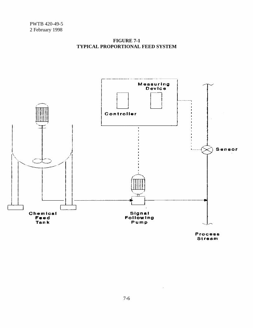
PWTB 420-49-52 February 1998
7-6
FIGURE 7-1TYPICAL PROPORTIONAL FEED SYSTEM
PWTB 420-49-52 February 1998
8-1
Chapter 8
Chemical Cleaning
Section IGeneral Information
8-1. General guidance. Chemical cleaning is required to remove millscale, oil, grease and other debris resultingfrom installation of new equipment ormaintenance and repair of old equipment, andto remove scale and deposits accumulatedduring system operation. Chemical cleaning ofexisting systems is not a normal or routineprocedure. In fact, the need to chemicallyclean a boiler in a manned heating plantindicates a need to improve the chemicaltreatment program.
a. New boilers should be thoroughlycleaned with an alkaline solution at elevatedtemperature (boilout) to remove oils andgreases left from construction. A typicalcleaning solution consists of 24 pounds causticsoda, 24 pounds trisodium phosphate (TSP) ordisodium phosphate, 8 pounds sodium nitrateand 0.5 pounds wetting agent in 1,000 gallonswater. Boilout is generally done by thecontractor installing the boiler.
b. Information and procedures in thischapter are general in nature and need to bemodified to fit specific applications.
c. The chemical cleaning of an industrialwater system should never be attempted byinexperienced personnel. For some cleaningjobs, such as large boilers and cooling towers,it may be advisable to engage a servicecompany specializing in chemical cleaning. Ifthe cleaning is contracted out, it is vital thatadequate lines of communications beestablished, and that safety proceduresemployed by the service company comply withArmy regulations. An orientation meeting
should be scheduled between Army andservice company representatives. At that time,the scope of the work can be defined, properprocedures initiated, the nature of the hazardsthoroughly discussed and users of the facilitynotified. Many times proprietary cleaningchemicals may be involved and disclosure ofthese chemicals should be made at theorientation meeting. Army policies andrestrictions can also be explained.
8-2. Reason for cleaning.Consistent application of a good watertreatment program is essential to minimizescale and corrosion problems in industrialwater systems. However, scale and depositswhich may form will require maintenancecleaning (descaling). If not removed, thesescale and deposits may impair the safety ofoperating personnel, interfere with heattransfer and cause excessive damage to ordestruction of the equipment. Cleaning is notappropriate for the removal of deposits whencorrosion of the system has advanced to thepoint where a large number of leaks may becreated.
8-3. Types of deposits:a. The deposits encountered in water
systems can be inorganic mineral salts andcorrosion products as well as those that areorganic or biological in nature. Deposits rangefrom very dense crystalline structures, to veryporous, loosely bound materials, to gelatinousslimes. Most water-formed deposits consist ofcorrosion products such as iron and copperoxides, mineral scales or mixtures.
b. Waterside deposits in heat exchangersare usually carbonate-based scales, while
PWTB 420-49-52 February 1998
8-2
steam side deposits may be a mixture ofmetallic oxides and organic residuals fromlubricating oil, particularly where reciprocatingtype engines are used. In steam systems, theoxides are usually iron and copper resultingfrom aggressive condensate. Microbiologicaldeposits may form in cooling systems frombacterial or algae growths, or fromdecomposition products of variousmicroorganisms.
c. Boiler deposits may take various forms.In low pressure boilers using a relatively hardfeedwater, deposits are essentially calcium andmagnesium, silicates, sulfates, carbonates,phosphates and hydroxides, plus someorganics. Deposits may also containconsiderable amounts of silica, iron, andcopper. The characteristics of such depositscan run from spongy, porous to relativelyhard, glass-like deposits. The latter depositsoccur where silica is present in appreciablequantities in the boiler water. Deposits inmedium to high-pressure boiler systemsusually are mixtures of iron and copper oxidesand phosphates. Dense deposits may tend toform in high heat transfer areas. Considerablequantities of "sludge type" accumulations maybe found in downcomers, mud drums,waterwall headers, crossover tubes and areasof low water circulation in the boiler.
Section IICleaning Procedures
8-4. Cleaning methods:a. The oldest techniques of deposits
removal utilize mechanical methods. To do anadequate mechanical cleaning job, theequipment may need to be partially or entirelydismantled. Even when equipment isdismantled, some areas may be extremelydifficult to reach. Chemical cleaning has
largely replaced mechanical cleaning ofprocess equipment as the most satisfactorymethod of removing deposits. However,mechanical methods such as wire brushing,tumbling, scraping and abrasive blasting withsand, grit, etc. are still employed in specialapplications.
b. Cleaning agents may be broadlyclassified as acid, alkaline, organic or solventcleaners. There is no general or universalcleaner to remove all deposits. The selectionof a solvent or cleaning agent must be basedon the material's ability to remove or dissolvethe deposit, on cost considerations, safetyhazards and the effect of the cleaning materialon the metals involved.
c. General guidance and procedures forpreparing solutions of hydrochloric (muriatic)acid and sulfamic acid are provided inparagraphs 8-5 and 8-6.
8-5. Hydrochloric (muriatic) acid. Inhibited hydrochloric (muriatic) acid instrengths of 5 to 20 percent is a very effectivescale remover. However, for mostapplications, a 10 percent solution is adequate.The following formulation is for a 10 percenthydrochloric acid solution. It is designed forremoving scale consisting primarily ofcarbonates with lesser amounts of phosphates,sulfates and silicates typically found in a steamboiler system containing copper alloys andtreated with a phosphate base program.Depending on the specific descalingapplication some of these ingredients can beomitted from the formulation. For example,diethylthiourea does not need to be added ifthere is no copper in the system. Where thereis only carbonate scale to be removed,ammonium bifluoride may be omitted. Awetting agent is preferable but not absolutelynecessary.
a. To make one thousand (1,000) gallons of
PWTB 420-49-52 February 1998
8-3
a 10 percent solution:(1) Add two hundred eighty-five (285)
gallons concentrated (36% strength)hydrochloric acid, Federal Specification O-H-765, to about 600 gallons of water.
(2) Add an amount of corrosioninhibitor, Military Specification MIL-1-17433,recommended by the manufacturer to thediluted acid solution. The inhibitor must becompatible with hydrochloric acid and mustnot precipitate under any condition during thecleaning operation.
(3) In a separate tank containing about75 gallons water:
(a) Add eighty-five (85) pounds ofone, three (1,3) diethylthiourea to complex anycopper and keep it from depositing. Do notuse the diethylthiourea as the corrosioninhibitor required in (2) above.
(b) Add one hundred-twenty (120)pounds of ammonium bifluoride, technicalgrade, to help dissolve certain iron and silicascales.
(c) Add 1 gallon of wetting agent,Military Specification MIL-D-16791.
(4) Add the dissolved diethylthiourea,ammonium bifluoride, and wetting agent to thediluted acid solution. Add sufficient water toobtain 1,000 gallons.
b. Carbonate deposits dissolve rapidly inhydrochloric acid with evolution of free carbondioxide. The escaping carbon dioxide tends tocreate some circulation or agitation of theacid, which insures the continual contact offresh acid with the scale. Once the carbonatehas been dissolved from a mixed deposit, aloose, porous structure may be left behind,which disintegrates or can be effectivelyremoved from the equipment by washing withhigh pressure water or by mechanical means.
c. The removal of phosphate deposits canusually be affected by hydrochloric acid.However, phosphate deposits have a tendency
to go into solution rather slowly. To keep thetotal cleaning time within reason, a highertemperature usually is necessary to remove apredominantly phosphate scale.
d. Most metallic oxides that might be foundin deposits can be removed with hydrochloricacid. The rate of the dissolution is a functionof temperature and solution velocity.
e. Heavy silica and sulfate scales are almostimpossible to remove with hydrochloric acid.Special chemicals and procedures are requiredto remove these scales.
f. Hydrochloric acid should not be used toclean stainless steel because the chloride ionmay cause pitting or stress corrosion cracking.Also, hydrochloric acid should not be used forremoving scale from galvanized steel surfacessince the zinc in the galvanizing is corroded byit.
8-6. Sulfamic acid. Sulfamic acid is an odorless, white, crystallinesolid organic acid readily soluble in water. Aninhibited sulfamic acid compound, in a drypowder form, is available under MilitarySpecification MIL-B-24155. A 5 to 20percent solution (5 to 20 pounds to about 10gallons water) is generally used for removingscale from metal surfaces.
a. Carbonate deposits are dissolved insulfamic acid in a similar manner as inhydrochloric acid. All the common sulfamatesalts (including calcium) are very soluble inwater.
b. The dry powder form of sulfamic acid issafer to handle than hydrochloric acid.Aqueous solutions of sulfamic acid, however,are generally much slower in action andrequires heating to provide effective scaleremoval. To obtain the same fast cleaningtime achieved with hydrochloric acid at roomtemperature the sulfamic acid solution must beheated to 130 to 160oF. One exception is
PWTB 420-49-52 February 1998
8-4
sulfate scale. Sulfamic acid is more effectiveon sulfate scale than hydrochloric acid.
c. Inhibited sulfamic acid used attemperatures up to 110oF will not corrodegalvanized steel, and is recommended forremoving scale in cooling towers, evaporativecondensers, and other equipment containinggalvanized steel. In general, sulfamic acid canbe applied to equipment while operating, butshould be drained from the system after a fewhours.
d. Commercially prepared descalingcompounds consisting of concentrated ordiluted inhibited acid (containing 7 to 28percent of the acid and inhibitor) may bepurchased under various trade names at prices4 to 30 times the costs of the ingredients whenpurchased as generic chemicals.
(1) Advertisements of some of theseproducts may claim that cotton clothes andskin are not attacked by the acid. These claimsare usually based on the use of such a dilutesolution of the acid that attack on clothes andskin is minimal, however, the economics ofscale removal is seriously affected. Recognizethat the handling of acid in any strength mustbe performed with considerable care andcaution.
(2) Since the cost of diluted acid isexpensive, Army personnel are encouraged topurchase the concentrated acid undergovernment specifications, dilute to usablestrengths, and add necessary corrosioninhibitors (see paragraph 8-5). Users of smallquantities (possibly less than 10 gallons ofdiluted acid per year) may not be able to justifythe purchased of undiluted acid and thespending of time, cost and effort to prepare thecleaning solution. Therefore, consider yourown requirements before ordering.
8-7. Preparation for cleaning.The unit to be cleaned must be isolated from
other parts of the system. For systems whichcannot be isolated by closing valves, isolationmay be accomplished using rubber blankets,wooden bulkheads with seals, inflatable nylonor rubber bags, rubber sponge-covered plugs,blind flanges and steel plates with rubber seals.Long lines may require auxiliary connectionsfor chemical cleaning.
a. Decide whether to clean by a soakingprocess, or by circulation of the cleaningsolution (see paragraph 8-8). In either case,temporary piping or hose lines will be requiredfrom the cleaning solution mixing tanks ortrucks to the unit, with return lines to tanks ordrains. Proper precautions and adequateprovisions must be made to protect equipment,isolate control lines, replace liquid level sightglasses with expendable materials and providesuitable points for checking temperatures. Itmay be mandatory to remove certain systemcomponents which cannot stand up under thecleaning cycle.
b. Complete cleaning procedure must beworked out in detail before starting chemicalcleaning operations. Some of the factors to beconsidered are methods for controllingtemperatures, means of mixing, heating andcirculating the chemical solution, properventing of dangerous gases from equipment toa safe area, and means for draining, filling andflushing under inert atmospheres. Samplingpoints, test procedures and control limits alsoneed to be engineered.
8-8. Methods for removing scale. Removal of scale may be done by circulatingthe inhibited acid solution through theequipment or by soaking the equipment in atank of the inhibited acid. Before starting anydescaling process the acid descalant must bechecked to make sure it is properly inhibited.This is done by placing a mild steel couponinto a breaker containing the prepared diluted

PWTB 420-49-52 February 1998
8-5
acid. No reaction should be noticed aroundthe coupon. If a reaction generating hydrogengas bubbles around the coupon is observed,additional inhibitor must be added.
a. Recirculating process for boilers. Thefollowing procedures are applicable forcleaning small boilers or other systems that canaccommodate a hot recirculating acid solution.
(1) Fill the boiler or system withpreheated 160 to 170oF dilute acid solution.
(2) Allow the dilute acid solution tosoak for 8 hours. Circulate the acid solutionfor about 15 minutes each hour at a rate ofabout 50 gal/min.
(3) Keep the temperature of the acidsolution between 160 and 170oF. Measure andrecord the temperature at least every 30minutes.
(4) Check and record the acid strength(see paragraph 8-9) at least every hour.
(5) Drain the system by forcing out theacid solution with 40 to 50 psi nitrogen;Federal Specification BB-N-411, Class 1. Ifleaks develop when the system is undernitrogen pressure, an alternate method forremoving the acid must be used such aspumping.
(6) Fill the boiler with preheated 150to 160oF water and soak at this temperaturefor 15 minutes.
(7) Drain under nitrogen pressure at40 to 50 psi.
(8) Prepare a mild acid rinse solutionas follows: Add 2 gallons of hydrochloric acid(Federal Specification O-H-765) for each1,000 gallons water. Also add corrosioninhibitor, Military Specification MIL-1-17433,in the amount recommended by themanufacturer.
(9) Fill the boiler with the preheated160 to 170oF mild acid rinse solution and soakfor 30 minutes.
(10) Drain the mild acid rinse undernitrogen pressure at 40 to 50 psig. Maintainnitrogen on the boiler to prevent air fromleaking inside.
(11) Prepare passivating solution asfollows: To each 1,000 gallons of distilledwater (or other water with less than 50 ppmtotal hardness (as CaCO3)), add 80 pounds ofpassivator compound, Military SpecificationMIL-P-24183, 0.5 percent by weight sodiumnitrite (Federal Specification O-S-639), and0.25 percent by weight monosodiumphosphate (Military Specification MIL-S-13727).
(12) Fill the boiler with the passivatingsolution preheated to 150 to 160oF, circulatefor 10 minutes, and hold in boiler at 150 to160oF for an additional 30 minutes.
(13) Drain and rinse boiler until the pHof the rinse water is between 8 and 10.
b. Circulating method without heat. Atypical process for descaling smaller typeequipment, such as enclosed vessels or hotwater heater coils, without heating the acidsolution is as follows:
(1) Note that an acid cleaningassembly may consist of a small cart on whichis mounted a pump and a 5 to 50 gallon steelor polyethylene tank with a bottom outlet tothe pump.
(2) Install sill cocks at the bottom ofthe water inlet of the heat exchanger and at thetop of the water outlet so that a return line canbe connected directly from the acid pump andfrom the heat exchanger to the acid tank.
(3) Prepare an inhibited acid cleaningsolution (see paragraph 8-5 or 8-6).
(4) Pump acid solution into the heatexchanger through the hose connection.Continue circulation until the reaction iscomplete as indicated by subsidence offoaming or depletion of the acid.
PWTB 420-49-52 February 1998
8-6
(5) If the scale is not completelyremoved, check the acid strength in the system(see paragraph 8-9). If less than 3 percent,add fresh acid solution and continuecirculation until the remaining scale isremoved. Usually an hour of circulation isadequate.
(6) Drain the heat exchanger.(7) Neutralize remaining acid by
circulating a 1 percent sodium carbonate (sodaash) solution (about 8 lb/100 gal) for about 10minutes.
(8) Rinse thoroughly with water untilthe pH of the rinse water is between 8 and 10.
c. Fill and soak method:(1) Prepare an inhibited dilute acid
solution (see paragraph 8-5 or 8-6) in asuitable size container.
(2) Depending on the item beingcleaned and the types of scale involved, it maybe desirable to place an agitator (mixer) in thetank or install a pump outside the tank tocirculate the acid solution. Also, a method toheat the acid may be required such as the useof a steam coil. All equipment must beexplosion proof and acid resistant.
(3) Immerse the item to be cleaned inthe dilute acid solution. Continue soakinguntil the reaction is complete as indicated bythe subsidence of foaming or depletion of theacid.
(4) If the scale is not completelyremoved, check the acid strength (seeparagraph 8-9). If less than 3 percent, addadditional acid and continue soaking the itemsuntil the remaining scale is dissolved. Usuallyone to two hours of soaking is adequate.
(5) Remove item from tank.(6) To neutralize remaining acid,
immerse the item in a 1 percent sodiumcarbonate (soda ash) solution (about 8 lb/100gal) for about 2 to 3 minutes.
(7) Thoroughly rinse with water.
8-9. Checking strength of acid solution.The initial strength of the dilute acid will varyfrom about 5 to 20 percent, although about 10percent is typical. As the acid is consumed indissolving scale, the strength of the acid isdecreased. Periodically, during a cleaningoperation the strength of the acid solutionshould be measured. When it falls belowabout 3 percent, the solution may be discardedsince most of its scale dissolving capability willhave been used. The procedure to check theacid strength is as follows:Apparatus:
Burette, 25 ml Automatic (for sodiumhydroxide solution)
Bottle, w/Dropper, 2 oz. (forphenolphthalein indicator solution)
Graduated Cylinder, 10 mlCasserole, Porcelain, heavy duty, 210 ml
capacityStirring Rod
Reagents:Sodium Hydroxide Solution, 1.0 NPhenolphthalein Indicator Solution, 0.5
percentMethod:1. Measure 10 ml of the acid solution
accurately in the graduated cylinder.2. Pour into the casserole.3. Add 2 to 4 drops of Phenolphthalein
Indicator Solution to the casserole and stir.4. Fill the automatic burette with the 1.0 N
Sodium Hydroxide Solution, then allow theexcess to drain back into the bottle.
5. While stirring the acid solution constantly,add Sodium Hydroxide Solution from theburette to the casserole until color changesto a permanent faint pink. This is theendpoint. Read the burette to the nearest0.1 ml.
Results:1. For Hydrochloric Acid:

PWTB 420-49-52 February 1998
8-7
Percent Hydrochloric Acid = ml of1.0 N Sodium Hydroxide x 0.36
2. For Sulfamic Acid:Percent Sulfamic Acid = ml of 1.0N Sodium Hydroxide x 0.97*
PWTB 420-49-52 February 1998
A-1
Appendix A
REFERENCES
Government PublicationsDepartment of the Army
AR 420-49 Utility ServicesTM 5-650 Central Boiler PlantTM 5-660 Maintenance and Operation of Water Supply, Treatment, and Distribution
Systems.
Nongovernment PublicationsNational Association of Corrosion Engineers (NACE)
TPC Publication 1; Cooling Water Treatment ManualAmerican Society of Mechanical Engineers (ASTM)
Performance Test Codes
PWTB 420-49-52 February 1998
B-1
Appendix B
Practical (Puckorius) Scaling Index (PSI)
B-1. Development of PSI.a. Historically, the Langelier Saturation
Index (LSI) and the Ryznar Stability Index(RSI) have been used to predict the tendencyof a water to be scale forming or scaledissolving. Both are based on the pH ofsaturation (pHs) for calcium carbonate under aspecific water condition. Both indices use themeasured pH of the cooling water.
(1) LSI = (measured pH) - (pHs). Apositive value indicates scale; a negative value,no scale.
(2) RSI = (2 pHs) - (measured pH).A value below 6 means scale; above 6, noscale.
b. Use of LSI and RSI sometimes gaveinconsistent or even conflicting results. Basedon a long term study relative to calciumcarbonate scale formation when applying boththe LSI and RSI, P.R. Puckorius and J.M.Brooke developed a new index that givesmuch better and more consistent indication ofscaling conditions of cooling water. The newindex, the Practical Scaling Index (PSI), orsometimes called the Puckorius Scaling Index,is based on correction of the system pH tomatch the total alkalinity of the water beingevaluated. This is necessary because the pH isoften buffered, causing the pH to not relatecorrectly to the bicarbonate alkalinity, one ofthe factors in the pHs calculation. To calculatethe PSI, the pHs is determined in the samemanner as for the LSI and RSI. Next, anadjusted or equilibrium pH (pHeq) is obtainedfrom a total alkalinity/pH chart (paragraph B-3and table B-5). The value of pHeq rather thanmeasured pH is used in the
following formula:PSI = (2 pHs) - (pHeq)
A value below 6 means scale; above 6, noscale.
B-2. Calculating pH of saturation (pHs).The pH of saturation (pHs) can be
determined from the relationship betweenvarious characteristics of water. Thefollowing factors and formula are used indetermining the pHs:
(1) Factors Needed to Calculate pHs:A = Total Dissolved Solids (ppm), table B-1B = Temperature (oF), table B-2C = Calcium Hardness (ppm as CaCO3),table B-3D = Total Alkalinity (ppm as CaCO3), tableB-4
(2) pHs = 9.30 + A + B - (C + D)(3) Example B-1: Water from a cooling
tower has a TDS of 1,000 ppm, calciumhardness of 500 ppm (as CaCO3), totalalkalinity of 100 ppm (as CaCO3) andmeasured pH of 8.2. The hottest temperatureon the waterside of the heat exchanger is120oF.
pHs = 9.30 + A + B - (C + D)pHs = 9.30 + 0.20 + 1.57 - (2.30+2.00) = 6.77
B-3. Calculating equilibrium pH (pHeq).Puckorius and Brooke developed the
improved relationship between total alkalinityand pH after studying hundreds of coolingsystems over some 20 years. The pHeq valuesshown in table B-5 for the total alkalinitymeasured in the cooling water are used forcalculating the PSI.
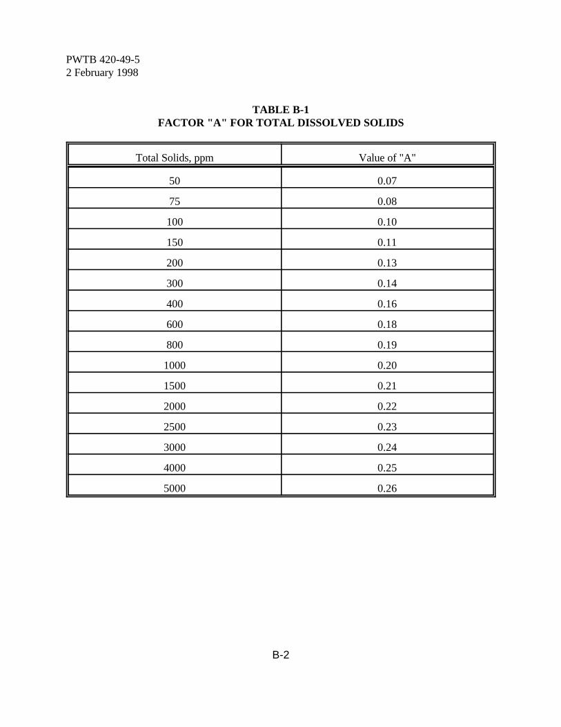
PWTB 420-49-52 February 1998
B-2
TABLE B-1FACTOR "A" FOR TOTAL DISSOLVED SOLIDS
Total Solids, ppm Value of "A"
50 0.07
75 0.08
100 0.10
150 0.11
200 0.13
300 0.14
400 0.16
600 0.18
800 0.19
1000 0.20
1500 0.21
2000 0.22
2500 0.23
3000 0.24
4000 0.25
5000 0.26
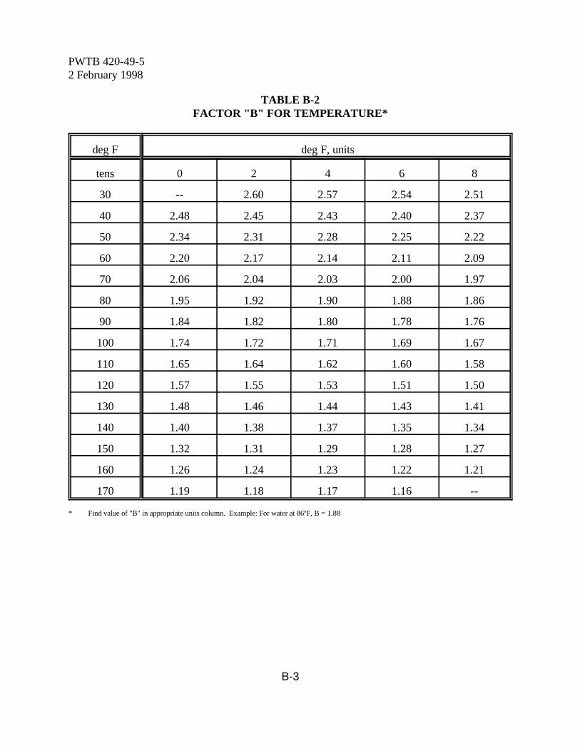
PWTB 420-49-52 February 1998
B-3
TABLE B-2FACTOR "B" FOR TEMPERATURE*
deg F deg F, units
tens 0 2 4 6 8
30 -- 2.60 2.57 2.54 2.51
40 2.48 2.45 2.43 2.40 2.37
50 2.34 2.31 2.28 2.25 2.22
60 2.20 2.17 2.14 2.11 2.09
70 2.06 2.04 2.03 2.00 1.97
80 1.95 1.92 1.90 1.88 1.86
90 1.84 1.82 1.80 1.78 1.76
100 1.74 1.72 1.71 1.69 1.67
110 1.65 1.64 1.62 1.60 1.58
120 1.57 1.55 1.53 1.51 1.50
130 1.48 1.46 1.44 1.43 1.41
140 1.40 1.38 1.37 1.35 1.34
150 1.32 1.31 1.29 1.28 1.27
160 1.26 1.24 1.23 1.22 1.21
170 1.19 1.18 1.17 1.16 --
* Find value of "B" in appropriate units column. Example: For water at 86oF, B = 1.88
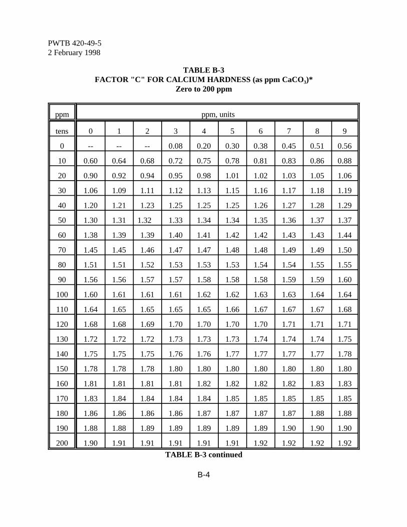
PWTB 420-49-52 February 1998
B-4
TABLE B-3FACTOR "C" FOR CALCIUM HARDNESS (as ppm CaCO3)*
Zero to 200 ppm
ppm ppm, units
tens 0 1 2 3 4 5 6 7 8 9
0 -- -- -- 0.08 0.20 0.30 0.38 0.45 0.51 0.56
10 0.60 0.64 0.68 0.72 0.75 0.78 0.81 0.83 0.86 0.88
20 0.90 0.92 0.94 0.95 0.98 1.01 1.02 1.03 1.05 1.06
30 1.06 1.09 1.11 1.12 1.13 1.15 1.16 1.17 1.18 1.19
40 1.20 1.21 1.23 1.25 1.25 1.25 1.26 1.27 1.28 1.29
50 1.30 1.31 1.32 1.33 1.34 1.34 1.35 1.36 1.37 1.37
60 1.38 1.39 1.39 1.40 1.41 1.42 1.42 1.43 1.43 1.44
70 1.45 1.45 1.46 1.47 1.47 1.48 1.48 1.49 1.49 1.50
80 1.51 1.51 1.52 1.53 1.53 1.53 1.54 1.54 1.55 1.55
90 1.56 1.56 1.57 1.57 1.58 1.58 1.58 1.59 1.59 1.60
100 1.60 1.61 1.61 1.61 1.62 1.62 1.63 1.63 1.64 1.64
110 1.64 1.65 1.65 1.65 1.65 1.66 1.67 1.67 1.67 1.68
120 1.68 1.68 1.69 1.70 1.70 1.70 1.70 1.71 1.71 1.71
130 1.72 1.72 1.72 1.73 1.73 1.73 1.74 1.74 1.74 1.75
140 1.75 1.75 1.75 1.76 1.76 1.77 1.77 1.77 1.77 1.78
150 1.78 1.78 1.78 1.80 1.80 1.80 1.80 1.80 1.80 1.80
160 1.81 1.81 1.81 1.81 1.82 1.82 1.82 1.82 1.83 1.83
170 1.83 1.84 1.84 1.84 1.84 1.85 1.85 1.85 1.85 1.85
180 1.86 1.86 1.86 1.86 1.87 1.87 1.87 1.87 1.88 1.88
190 1.88 1.88 1.89 1.89 1.89 1.89 1.89 1.90 1.90 1.90
200 1.90 1.91 1.91 1.91 1.91 1.91 1.92 1.92 1.92 1.92
TABLE B-3 continued
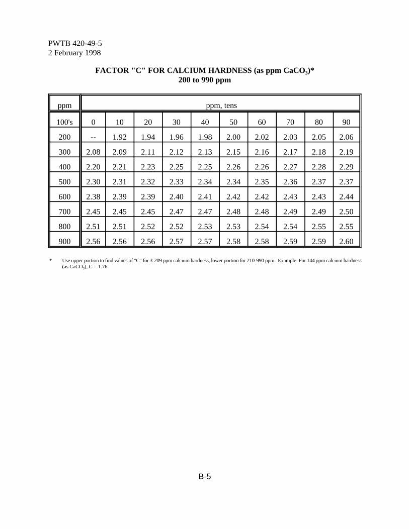
PWTB 420-49-52 February 1998
B-5
FACTOR "C" FOR CALCIUM HARDNESS (as ppm CaCO3)*200 to 990 ppm
ppm ppm, tens
100's 0 10 20 30 40 50 60 70 80 90
200 -- 1.92 1.94 1.96 1.98 2.00 2.02 2.03 2.05 2.06
300 2.08 2.09 2.11 2.12 2.13 2.15 2.16 2.17 2.18 2.19
400 2.20 2.21 2.23 2.25 2.25 2.26 2.26 2.27 2.28 2.29
500 2.30 2.31 2.32 2.33 2.34 2.34 2.35 2.36 2.37 2.37
600 2.38 2.39 2.39 2.40 2.41 2.42 2.42 2.43 2.43 2.44
700 2.45 2.45 2.45 2.47 2.47 2.48 2.48 2.49 2.49 2.50
800 2.51 2.51 2.52 2.52 2.53 2.53 2.54 2.54 2.55 2.55
900 2.56 2.56 2.56 2.57 2.57 2.58 2.58 2.59 2.59 2.60
* Use upper portion to find values of "C" for 3-209 ppm calcium hardness, lower portion for 210-990 ppm. Example: For 144 ppm calcium hardness(as CaCO3), C = 1.76
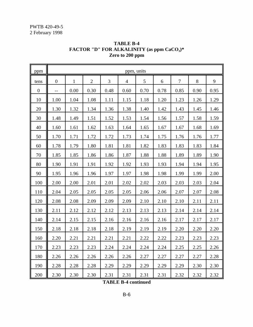
PWTB 420-49-52 February 1998
B-6
TABLE B-4FACTOR "D" FOR ALKALINITY (as ppm CaCO3)*
Zero to 200 ppm
ppm ppm, units
tens 0 1 2 3 4 5 6 7 8 9
0 -- 0.00 0.30 0.48 0.60 0.70 0.78 0.85 0.90 0.95
10 1.00 1.04 1.08 1.11 1.15 1.18 1.20 1.23 1.26 1.29
20 1.30 1.32 1.34 1.36 1.38 1.40 1.42 1.43 1.45 1.46
30 1.48 1.49 1.51 1.52 1.53 1.54 1.56 1.57 1.58 1.59
40 1.60 1.61 1.62 1.63 1.64 1.65 1.67 1.67 1.68 1.69
50 1.70 1.71 1.72 1.72 1.73 1.74 1.75 1.76 1.76 1.77
60 1.78 1.79 1.80 1.81 1.81 1.82 1.83 1.83 1.83 1.84
70 1.85 1.85 1.86 1.86 1.87 1.88 1.88 1.89 1.89 1.90
80 1.90 1.91 1.91 1.92 1.92 1.93 1.93 1.94 1.94 1.95
90 1.95 1.96 1.96 1.97 1.97 1.98 1.98 1.99 1.99 2.00
100 2.00 2.00 2.01 2.01 2.02 2.02 2.03 2.03 2.03 2.04
110 2.04 2.05 2.05 2.05 2.05 2.06 2.06 2.07 2.07 2.08
120 2.08 2.08 2.09 2.09 2.09 2.10 2.10 2.10 2.11 2.11
130 2.11 2.12 2.12 2.12 2.13 2.13 2.13 2.14 2.14 2.14
140 2.14 2.15 2.15 2.16 2.16 2.16 2.16 2.17 2.17 2.17
150 2.18 2.18 2.18 2.18 2.19 2.19 2.19 2.20 2.20 2.20
160 2.20 2.21 2.21 2.21 2.21 2.22 2.22 2.23 2.23 2.23
170 2.23 2.23 2.23 2.24 2.24 2.24 2.24 2.25 2.25 2.26
180 2.26 2.26 2.26 2.26 2.26 2.27 2.27 2.27 2.27 2.28
190 2.28 2.28 2.28 2.29 2.29 2.29 2.29 2.29 2.30 2.30
200 2.30 2.30 2.30 2.31 2.31 2.31 2.31 2.32 2.32 2.32
TABLE B-4 continued
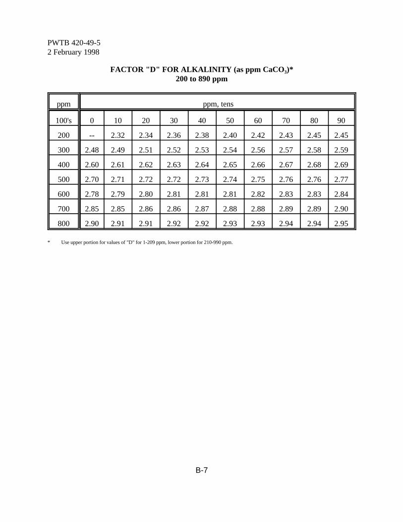
PWTB 420-49-52 February 1998
B-7
FACTOR "D" FOR ALKALINITY (as ppm CaCO3)*200 to 890 ppm
ppm ppm, tens
100's 0 10 20 30 40 50 60 70 80 90
200 -- 2.32 2.34 2.36 2.38 2.40 2.42 2.43 2.45 2.45
300 2.48 2.49 2.51 2.52 2.53 2.54 2.56 2.57 2.58 2.59
400 2.60 2.61 2.62 2.63 2.64 2.65 2.66 2.67 2.68 2.69
500 2.70 2.71 2.72 2.72 2.73 2.74 2.75 2.76 2.76 2.77
600 2.78 2.79 2.80 2.81 2.81 2.81 2.82 2.83 2.83 2.84
700 2.85 2.85 2.86 2.86 2.87 2.88 2.88 2.89 2.89 2.90
800 2.90 2.91 2.91 2.92 2.92 2.93 2.93 2.94 2.94 2.95
* Use upper portion for values of "D" for 1-209 ppm, lower portion for 210-990 ppm.
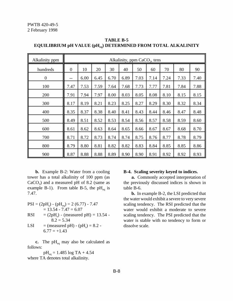
PWTB 420-49-52 February 1998
B-8
TABLE B-5EQUILIBRIUM pH VALUE (pHeq) DETERMINED FROM TOTAL ALKALINITY
Alkalinity ppm Alkalinity, ppm CaCO3, tens
hundreds 0 10 20 30 40 50 60 70 80 90
0 -- 6.00 6.45 6.70 6.89 7.03 7.14 7.24 7.33 7.40
100 7.47 7.53 7.59 7.64 7.68 7.73 7.77 7.81 7.84 7.88
200 7.91 7.94 7.97 8.00 8.03 8.05 8.08 8.10 8.15 8.15
300 8.17 8.19 8.21 8.23 8.25 8.27 8.29 8.30 8.32 8.34
400 8.35 8.37 8.38 8.40 8.41 8.43 8.44 8.46 8.47 8.48
500 8.49 8.51 8.52 8.53 8.54 8.56 8.57 8.58 8.59 8.60
600 8.61 8.62 8.63 8.64 8.65 8.66 8.67 8.67 8.68 8.70
700 8.71 8.72 8.73 8.74 8.74 8.75 8.76 8.77 8.78 8.79
800 8.79 8.80 8.81 8.82 8.82 8.83 8.84 8.85 8.85 8.86
900 8.87 8.88 8.88 8.89 8.90 8.90 8.91 8.92 8.92 8.93
b. Example B-2: Water from a coolingtower has a total alkalinity of 100 ppm (asCaCO3) and a measured pH of 8.2 (same asexample B-1). From table B-5, the pHeq is7.47.
PSI = (2pHs) - (pHeq) = 2 (6.77) - 7.47= 13.54 - 7.47 = 6.07
RSI = (2pHs) - (measured pH) = 13.54 -8.2 = 5.34
LSI = (measured pH) - (pHs) = 8.2 - 6.77 = +1.43
c. The pHeq may also be calculated asfollows:
pHeq = 1.485 log TA + 4.54where TA denotes total alkalinity.
B-4. Scaling severity keyed to indices. a. Commonly accepted interpretation of
the previously discussed indices is shown intable B-6.
b. In example B-2, the LSI predicted thatthe water would exhibit a severe to very severescaling tendency. The RSI predicted that thewater would exhibit a moderate to severescaling tendency. The PSI predicted that thewater is stable with no tendency to form ordissolve scale.
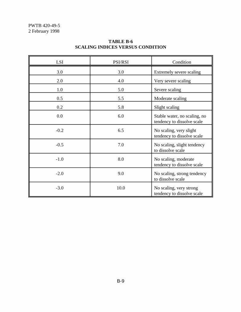
PWTB 420-49-52 February 1998
B-9
TABLE B-6SCALING INDICES VERSUS CONDITION
LSI PSI/RSI Condition
3.0 3.0 Extremely severe scaling
2.0 4.0 Very severe scaling
1.0 5.0 Severe scaling
0.5 5.5 Moderate scaling
0.2 5.8 Slight scaling
0.0 6.0 Stable water, no scaling, notendency to dissolve scale
-0.2 6.5 No scaling, very slighttendency to dissolve scale
-0.5 7.0 No scaling, slight tendencyto dissolve scale
-1.0 8.0 No scaling, moderatetendency to dissolve scale
-2.0 9.0 No scaling, strong tendencyto dissolve scale
-3.0 10.0 No scaling, very strongtendency to dissolve scale
PWTB 420-49-52 February 1998
C-1
Appendix C
Corrosion Testing With Coupon Type Test Specimens
C-1. Purpose. Corrosion tests with metalcoupon test specimens are used to determinehow corrosive a water is towards a specificmetal. Coupon test specimens are particularlyuseful in monitoring the effectiveness ofchemical corrosion control programs. Theextent of both general and localized corrosioncan be determined. Also, examination of thespecimens as they are removed from thesystem can provide information regardingdeposit accumulation or microbiological slimegrowth.
C-2. Application. a. The coupons are metal tags of various
sizes. Generally, low carbon steel specimensare used as the most susceptible metal tocorrosion; however, copper, stainless steel,brass and other metals are available for specialstudies. The specimens are prepared andcleaned to ensure uniformity and thenweighed. The general corrosion rate isdetermined after exposure. Coupons arecleaned and reweighed. Corrosion rates arecalculated based on the weight loss, time ofexposure and the area and specific gravity ofthe coupon, and are expressed in mils per year(mpy).
b. Since the goal of the corrosion testingprogram is to provide information regardingconditions within the system, the corrosioncoupons should be exposed to conditions thatreflect those in the system as a whole. Watervelocity and temperature will significantlyaffect the corrosion rate. Corrosion rates canbe significantly increased when velocity iseither too low or too high. For best results,water velocity flowing by the test specimenshould be 3 to 5 ft/sec and both adjustable andmeasurable. Temperature also affects the rate
of corrosion with higher temperatures usuallyincreasing corrosion. Therefore, in coolingwater systems both the cold supply water andthe hot return water should be evaluated withcorrosion coupons. When only one test rackcan be installed, the warm water return at thetower should be used which provides anaverage hot water temperature.
c. Expose corrosion coupons for aminimum of 30 calendar days and a maximumof 90 calendar days except for special tests.Although spot checks are useful, a regularschedule will determine trends and recognizechanges within the system. When corrosiontest specimens of different metals are installedin the same corrosion test rack, the more nobleor resistant metal should be downstream ofless resistant metals.
d. Specimens are shipped in vapor-inhibited bags. Do not remove them from thebags until the specimen is to be installed. Thevapor-inhibited bags should be saved forreturning exposed specimens. Do not handlespecimens directly with fingers since fingerprints can initiate corrosion sites. Record onthe appropriate form the exact location anddate of installation.
e. After the specimens have beenexposed for the desired time, (30, 60, or 90calendar days), carefully remove, air drywithout disturbing any deposits, and returnthem to the original vapor-inhibited bag.Record date of removal on the appropriateform. Then send the exposed specimens andcompleted forms to the supplier for evaluation.After evaluation, the results are presented andinterpreted in a written report.
C-3. Installation of coupon type testspecimens.
PWTB 420-49-52 February 1998
C-2
a. Coupons are usually installed in pipe"tees" by means of corrosion test racks whichinclude a 1 inch pipe plug, drilled and tappedto accept a plastic or phenolic rod with a nylonnut and bolt for attaching the coupon to therod. A bypass arrangement with 1 inch pipingas shown in figure C-1 will facilitateinstallation and removal as well as allow theuse of multiple specimens. Polyvinyl chloride(PVC) will eliminate electrical effects butcannot be used for hot condensate. Acorrosion test rack may be purchased orconstructed on site.
b. For steam and condensate returnlines, install coupons in any convenientlocation where there are "tees". When using abypass arrangement, condensate from theoutlet is piped back into the system. Bypassesshould be constructed of iron pipe and fittingsand installed only where there is sufficientpressure differential to ensure a continuousflow through the bypass.
c. To ensure proper results, thefollowing points should be checked:
(1) Flow through the corrosion testrack must be continuous and measurable. Useflow meters for all installations. When a flowmeter does not exist, flow must be measuredby timing how long it takes to fill a containerof known volume such as a five gallon pail.
(2) Normally, water velocity throughthe corrosion test rack should be 3 to 5 ft/sec.The velocities in ft/sec for given gpm flows forvarious pipe sizes are shown below:
Flow Rate in gpmVelocity 1" line 1-1/4" line 1-1/2" line3 8 14 195 13 23 30
d. Direction of flow should be as shownin figure C-1 to minimize turbulence aroundthe corrosion test specimen and ensure that thetest rack remains full of water.
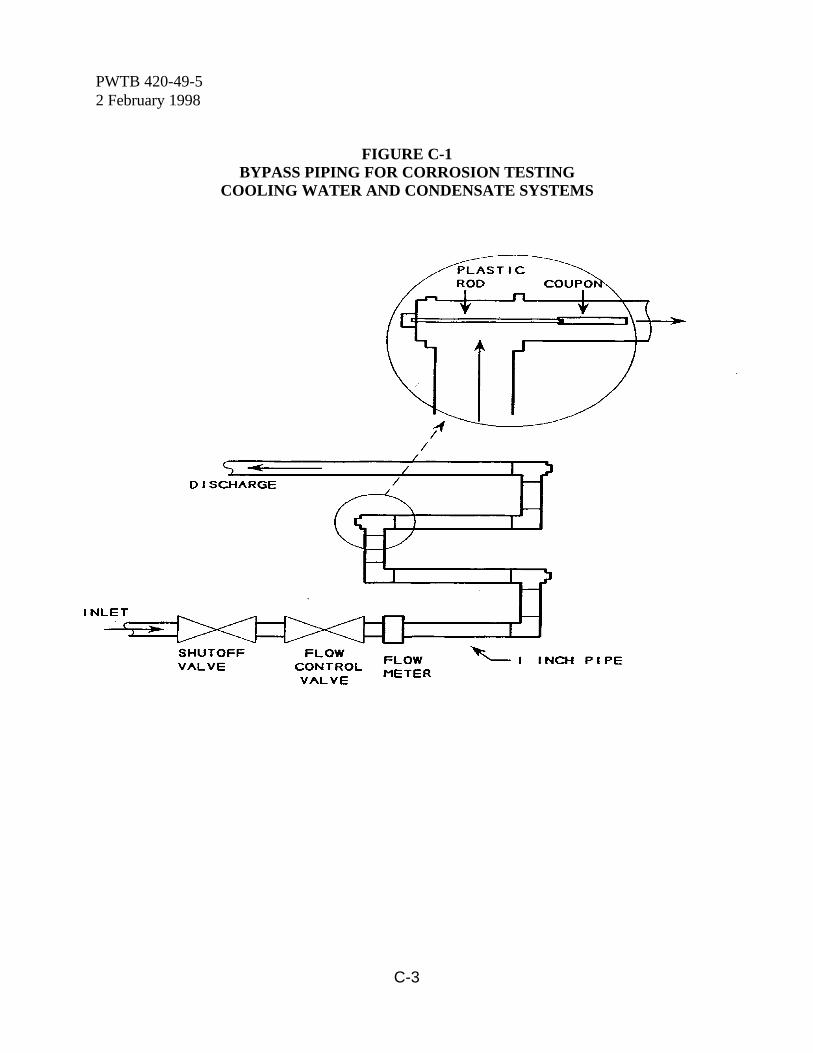
PWTB 420-49-52 February 1998
C-3
FIGURE C-1BYPASS PIPING FOR CORROSION TESTING
COOLING WATER AND CONDENSATE SYSTEMS
PWTB 420-49-52 February 1998
D-1
Appendix D
Corrosion Testing With Test Nipple Assembly
D-1. PURPOSE. Corrosion tests withmetal test specimens are used to determinehow corrosive a water is toward a specificmetal. Although test nipple assemblies(referred to as "tester") can be used in manyapplications; they are used on Armyinstallations to evaluate corrosion problemsin steam condensate return systems.
D-2. APPLICATION.a. The tester consists of three 3 inch by
3/4 inch NPT nipples, connected by twocouplings (see figure D-1). The centernipple contains short inserts machined fromsteel tubing similar to the steel pipe in thecondensate system. The outside diameter ofthe inserts is approximately the same as theinside diameter of the center 3/4 inchmachined coupling. The two end nipples ofthe tester are to be installed between twounions in such a manner that condensate willconstantly flow through the tester. Seeparagraph D-3 for detailed installationinstructions.
b. Serious corrosion is more likely inlarge area heating systems which have longreturn lines. More concentrated systems,such as laundries, and low-pressure closedsystems, in which there is very littlefeedwater makeup, generally experiencemuch less condensate return line corrosion.
c. Information obtained from one ortwo condensate return systems on an Armyinstallation is generally sufficient to serve asa survey of the entire facility, if the testpoints are well chosen. One or more testerswould be installed in the largest area heatingsystem and another in a smaller system. Thetesters should be installed at points where
maintenance work has been required due tocorrosion.
d. The tester is provided by the suppliercomplete and ready for installation. Anappropriate data form is also provided withthe tester. This form must be completed bythe user for correct interpretation ofcorrosion that may occur on the testerinserts. The user is required to draw apicture to show how and where the testerwas installed.
e. At the end of the test period, thetester is removed. The tester is rinsedinternally for several seconds with very hotwater, drained, and immediately capped onboth ends with the plastic caps which hadbeen supplied with the tester.
f. A condensate sample is collectedfrom the area where the tester was installedand returned to the supplier at the same timeas the tester.
g. The tester is packed in anyconvenient package, enclosing the completeddata sheet, and returned to the supplier.
D-3. INSTALLATION OF TESTER.a. Install the tester in a horizontal return
line. If morpholine treatment is being used,install the tester in a building near the end ofthe steam main where the treatment wouldbe expected to be least effective. If amixture of morpholine and cyclohexylamineis used, install a tester at each end of thesystem.
b. Insure representative sampling of thecondensate by the tester. Do not install thetester to receive drips from steam mains. Drips may be less corrosive (less acidic) thanthe average condensate.
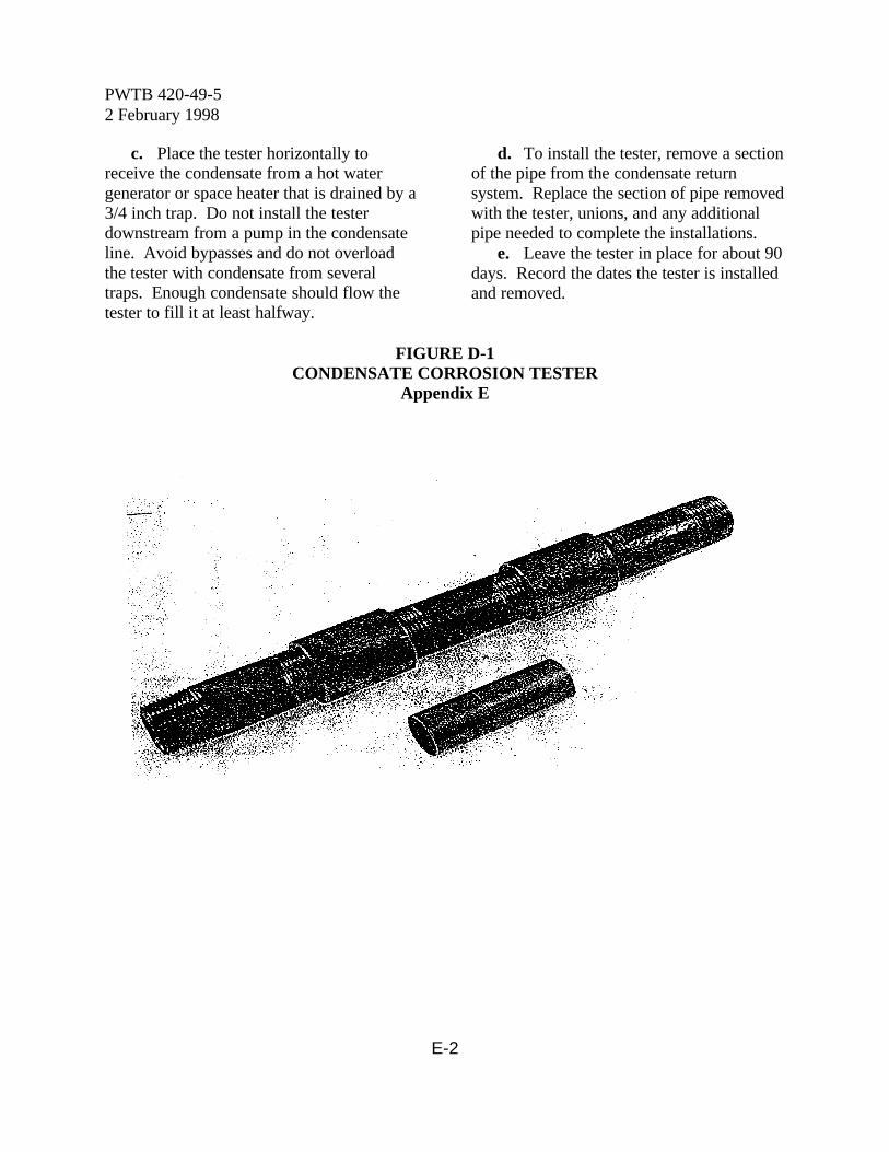
PWTB 420-49-52 February 1998
E-2
c. Place the tester horizontally toreceive the condensate from a hot watergenerator or space heater that is drained by a3/4 inch trap. Do not install the testerdownstream from a pump in the condensateline. Avoid bypasses and do not overloadthe tester with condensate from severaltraps. Enough condensate should flow thetester to fill it at least halfway.
d. To install the tester, remove a sectionof the pipe from the condensate returnsystem. Replace the section of pipe removedwith the tester, unions, and any additionalpipe needed to complete the installations.
e. Leave the tester in place for about 90days. Record the dates the tester is installedand removed.
FIGURE D-1CONDENSATE CORROSION TESTER
Appendix E
PWTB 420-49-52 February 1998
E-1
Testing Of Samples From Industrial Water Systems
E-1. Purpose of testing. Testing ofindustrial water is done to determine theamount of treatment chemicals in the waterso that dosage levels can be properlyregulated. These tests are the only knownmeans of having reliable operations, as far asthe water is concerned. Testing may beconducted in a permanent field laboratory orat the plant or site location using portabletest kits.
E-2. Use of portable test kits.Portable test kits are primarily for use at thesite location where the sample is taken. They also can be used in the permanent fieldlaboratory. Test procedures are providedwith the test kit. For tests that can beconducted in the field laboratory or with aportable test kit, use of field laboratory testprocedures is recommended for best results. The water analyst should periodically checkthe results of the portable test kit against thefield laboratory test on the same watersample. Portable test kits are available froma number of commercial sources.
E-3. Testing techniques. Accurate testresults depend on using the proper reagentsand following good, basic laboratoryprocedures and techniques.
a. The chemical reagents kept at eachfield laboratory should be specific for thetests that are performed. The amount onhand should be adjusted to ensure the supplyis fresh. Reagent containers must be tightlyclosed when not in use and stored in a coolplace. Except for reagents with a shortershelf life specified, the liquid reagents shouldbe consumed within 1 year and the dryreagents consumed within 2 years. Allreagents should be properly marked with
appropriate warning labels, batch controlnumbers, and date packaged or discard dateclearly marked.
b. Water analyses require certainchemical apparatus. These are scientificinstruments and are to be treated as such. The apparatus should be HANDLED WITHCARE! All of the apparatus will lastindefinitely if given proper care.
c. It is necessary to keep everything inGOOD ORDER at all times. Have a placefor everything and keep everything in itsplace! Be sure all bottles are properlylabeled and avoid mixing bottles! All bottlesshould be tightly closed. Keep any reservestock of solutions and reagents in a cool,dark place.
d. All equipment and apparatus,especially glassware, should be keptCLEAN! Unless this is done, the tests willnot be reliable and errors will be introduced. Thoroughly rinse and air dry all glasswareimmediately after use. If color apparatus isemployed, do not expose to heat or directsunlight. If any liquid is spilled on any of theequipment or apparatus, wipe off at once anddry.
e. MEASURE CAREFULLY! Theapparatus are precision instruments that arecapable of very fine measurements. Theresults will be "off" if: improper amounts ofsamples are taken, incorrect volumes ofsolution are added, the burette is not readcorrectly, or if the methods prescribed arenot performed exactly as written.
f. THE SUSPENDED MATTER ORSLUDGE will generally settle to the bottomif the sample is allowed to stand beforetesting. The clear water can then be used forthe tests, making it unnecessary to filter
PWTB 420-49-52 February 1998
E-2
(except for specific tests). Theoretically, allwater analyses should be made at 77oF(25oC); however, no appreciable error will beintroduced if the test is made between 68 and86oF (20 to 30oC). In general, the shorterthe time between the collection and theanalysis of the sample, the more reliable willbe the results.
g. When the water sample colorinterferes with the analysis it may benecessary to filter the sample throughactivated charcoal, except for the sulfite andnitrite tests.
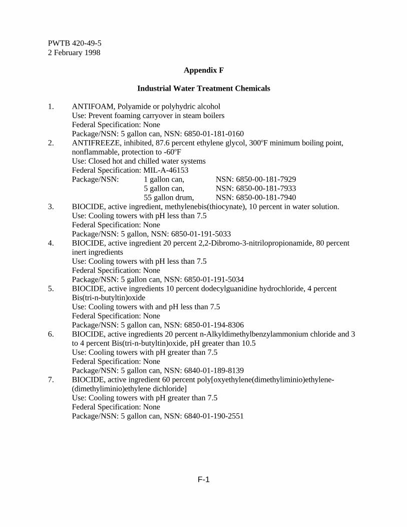
PWTB 420-49-52 February 1998
F-1
Appendix F
Industrial Water Treatment Chemicals
1. ANTIFOAM, Polyamide or polyhydric alcoholUse: Prevent foaming carryover in steam boilersFederal Specification: NonePackage/NSN: 5 gallon can, NSN: 6850-01-181-0160
2. ANTIFREEZE, inhibited, 87.6 percent ethylene glycol, 300oF minimum boiling point,nonflammable, protection to -60oFUse: Closed hot and chilled water systemsFederal Specification: MIL-A-46153Package/NSN: 1 gallon can, NSN: 6850-00-181-7929
5 gallon can, NSN: 6850-00-181-793355 gallon drum, NSN: 6850-00-181-7940
3. BIOCIDE, active ingredient, methylenebis(thiocynate), 10 percent in water solution.Use: Cooling towers with pH less than 7.5Federal Specification: NonePackage/NSN: 5 gallon, NSN: 6850-01-191-5033
4. BIOCIDE, active ingredient 20 percent 2,2-Dibromo-3-nitrilopropionamide, 80 percentinert ingredientsUse: Cooling towers with pH less than 7.5Federal Specification: NonePackage/NSN: 5 gallon can, NSN: 6850-01-191-5034
5. BIOCIDE, active ingredients 10 percent dodecylguanidine hydrochloride, 4 percentBis(tri-n-butyltin)oxideUse: Cooling towers with and pH less than 7.5Federal Specification: NonePackage/NSN: 5 gallon can, NSN: 6850-01-194-8306
6. BIOCIDE, active ingredients 20 percent n-Alkyldimethylbenzylammonium chloride and 3to 4 percent Bis(tri-n-butyltin)oxide, pH greater than 10.5Use: Cooling towers with pH greater than 7.5Federal Specification: NonePackage/NSN: 5 gallon can, NSN: 6840-01-189-8139
7. BIOCIDE, active ingredient 60 percent poly[oxyethylene(dimethyliminio)ethylene-(dimethyliminio)ethylene dichloride]
Use: Cooling towers with pH greater than 7.5Federal Specification: NonePackage/NSN: 5 gallon can, NSN: 6840-01-190-2551

PWTB 420-49-52 February 1998
F-2
8. BIOCIDE, active ingredients 60 percent consisting of 14 to 15 percent disodiumcyanodithioimidocarbonate and 20 to 21 percent potassium n-methyldithiocarbamateUse: Cooling towers with pH greater than 7.5Federal Specification: NonePackage/NSN: 5 gallon can, NSN: 6840-01-198-7945
9. BIOCIDE, active ingredient 96 to 98 percent 1-Bromo-3-chloro-5,5-dimethylhydantoin,granularUse: Remote cooling towers with any pHFederal Specification: NonePackage/NSN: 35 pound can, NSN: 6840-01-185-7455BORAX (see sodium nitrite-borax blend, item 40)
10. CALCIUM HYDROXIDE (slaked lime) (Ca(OH)2) technical, powder, 90 percentminimum by weightUse: Lime-soda ash water softeningFederal Specification: O-C-110Package/NSN: 50 pound bag, NSN: 6810-00-656-1091
11. CALCIUM HYPOCHLORITE, (Ca(OCl)2) technical, granular, 65 percent chlorine byweightUse: Algae control in cooling towers and disinfectant in treatment for Legionnaire'sDiseaseFederal Specification: O-C-114Package/NSN: 5 pound can, NSN: 6810-00-238-8115
100 pound drum, NSN: 6810-00-255-0472CAUSTIC SODA (see sodium hydroxide, item 35)
12. CYCLOHEXYLAMINE, boiler feedwater compound, neutralizing amine, all drums tobear adequate caution labels to protect against fire, poison and caustic burn hazardsUse: Control corrosion by CO2 in steam condensate linesFederal Specification: O-C-940Package/NSN: 60 percent, 400 pound drum, NSN: 6810-01-074-5201
60 percent, 15 gallon drum, NSN: 6810-00-515-223598 percent, 15 gallon drum, NSN: 6810-00-530-469598 percent, 55 gallon drum, NSN: 6810-00-805-9798
13. DIETHYLAMINOETHANOL (DEAE), 100 percent solutionUse: Control corrosion by CO2 in steam condensate linesFederal Specification: Package/NSN: 55 gallon drum, NSN: 6810-949-8331
14. DIPHOSPHONIC ACID (HEDP), 1-hydroxyethylidene 1,1-diphosphonic acid, activeingredient 58 to 62 percent, specific gravity 1.45 at 20oC/15oC, pH of 1 percent solutionless than 2.0Use: Inhibitor to prevent formation of calcium and magnesium scale in cooling waterapplicationsFederal Specification: NonePackage/NSN: 5 gallon can, NSN: 6850-01-190-5509
55 gallon drum, NSN: 6850-01-206-4601
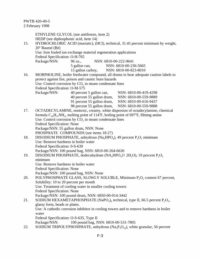
PWTB 420-49-52 February 1998
F-3
ETHYLENE GLYCOL (see antifreeze, item 2)HEDP (see diphosphonic acid, item 14)
15. HYDROCHLORIC ACID (muriatic), (HCl), technical, 31.45 percent minimum by weight,20o Baumé (Bé)Use: Iron fouled ion exchange material regeneration applicationsFederal Specification: O-H-765Package/NSN: 96 oz., NSN: 6810-00-222-9641
5 gallon can, NSN: 6810-00-236-566515 gallon carboy, NSN: 6810-00-823-8010
16. MORPHOLINE, boiler feedwater compound, all drums to bear adequate caution labels toprotect against fire, poison and caustic burn hazardsUse: Control corrosion by CO2 in steam condensate linesFederal Specification: O-M-575Package/NSN: 40 percent 5 gallon can, NSN: 6810-00-419-4298
40 percent 55 gallon drum, NSN: 6810-00-559-988991 percent 55 gallon drum, NSN: 6810-00-616-943798 percent 55 gallon drum, NSN: 6810-00-559-9888
17. OCTADECYLAMINE, nontoxic, creamy, white dispersion of octadecylamine, chemicalformula C18H37NH2, melting point of 114oF, boiling point of 697oF, filming amineUse: Control corrosion by CO2 in steam condensate linesFederal Specification: NonePackage/NSN: 55 gallon drum, NSN: NonePHOSPHATE COMPOUNDS (see items 18-27)
18. DISODIUM PHOSPHATE, anhydrous (Na2HPO4), 49 percent P2O5 minimumUse: Remove hardness in boiler waterFederal Specification: 0-S-639Package/NSN: 100 pound bag, NSN: 6810-00-264-6630
19. DISODIUM PHOSPHATE, dodecahydrate (NA2HPO41!2H2O), 19 percent P2O5
minimumUse: Remove hardness in boiler waterFederal Specification: NonePackage/NSN: 100 pound bag, NSN: None
20. POLYPHOSPHATE GLASS, SLOWLY SOLUBLE, Minimum P2O5 content 67 percent,Solubility: 10 to 20 percent per monthUse: Treatment of cooling water in smaller cooling towersFederal Specification: NonePackage/NSN: 100 pound drum, NSN: 6850-00-014-3442
21. SODIUM HEXAMETAPHOSPHATE (NaPO3)6 technical, type II, 66.5 percent P2O5,glassy form, beads or plates.Use: A cathodic corrosion inhibitor in cooling towers and to remove hardness in boilerwaterFederal Specification: O-S-635, Type IIPackage/NSN: 100 pound bag, NSN: 6810-00-531-7805
22. SODIUM TRIPOLYPHOSPHATE, anhydrous (Na5P3O10), white granular, 56 percent
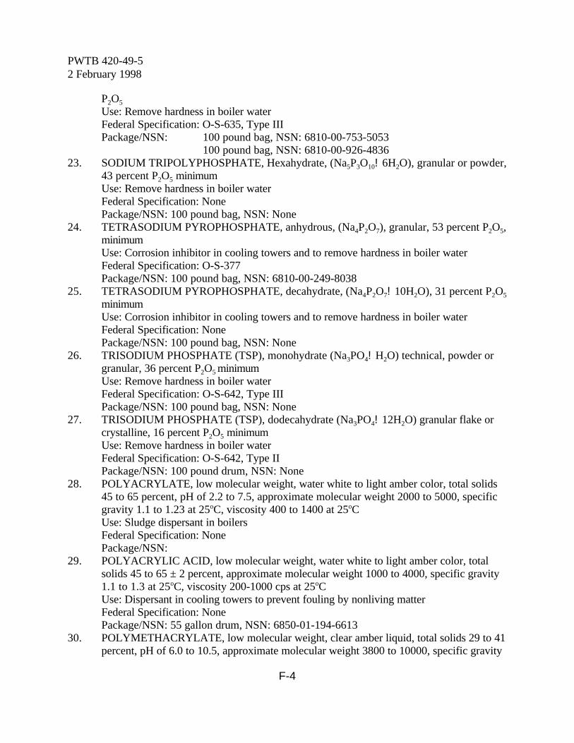
PWTB 420-49-52 February 1998
F-4
P2O5
Use: Remove hardness in boiler waterFederal Specification: O-S-635, Type IIIPackage/NSN: 100 pound bag, NSN: 6810-00-753-5053
100 pound bag, NSN: 6810-00-926-483623. SODIUM TRIPOLYPHOSPHATE, Hexahydrate, (Na5P3O10!6H2O), granular or powder,
43 percent P2O5 minimumUse: Remove hardness in boiler waterFederal Specification: NonePackage/NSN: 100 pound bag, NSN: None
24. TETRASODIUM PYROPHOSPHATE, anhydrous, (Na4P2O7), granular, 53 percent P2O5,minimumUse: Corrosion inhibitor in cooling towers and to remove hardness in boiler waterFederal Specification: O-S-377Package/NSN: 100 pound bag, NSN: 6810-00-249-8038
25. TETRASODIUM PYROPHOSPHATE, decahydrate, (Na4P2O7!10H2O), 31 percent P2O5
minimumUse: Corrosion inhibitor in cooling towers and to remove hardness in boiler waterFederal Specification: NonePackage/NSN: 100 pound bag, NSN: None
26. TRISODIUM PHOSPHATE (TSP), monohydrate (Na3PO4!H2O) technical, powder orgranular, 36 percent P2O5 minimumUse: Remove hardness in boiler waterFederal Specification: O-S-642, Type IIIPackage/NSN: 100 pound bag, NSN: None
27. TRISODIUM PHOSPHATE (TSP), dodecahydrate (Na3PO4!12H2O) granular flake orcrystalline, 16 percent P2O5 minimumUse: Remove hardness in boiler waterFederal Specification: O-S-642, Type IIPackage/NSN: 100 pound drum, NSN: None
28. POLYACRYLATE, low molecular weight, water white to light amber color, total solids45 to 65 percent, pH of 2.2 to 7.5, approximate molecular weight 2000 to 5000, specificgravity 1.1 to 1.23 at 25oC, viscosity 400 to 1400 at 25oCUse: Sludge dispersant in boilersFederal Specification: NonePackage/NSN:
29. POLYACRYLIC ACID, low molecular weight, water white to light amber color, totalsolids 45 to 65 ± 2 percent, approximate molecular weight 1000 to 4000, specific gravity1.1 to 1.3 at 25oC, viscosity 200-1000 cps at 25oCUse: Dispersant in cooling towers to prevent fouling by nonliving matterFederal Specification: NonePackage/NSN: 55 gallon drum, NSN: 6850-01-194-6613
30. POLYMETHACRYLATE, low molecular weight, clear amber liquid, total solids 29 to 41percent, pH of 6.0 to 10.5, approximate molecular weight 3800 to 10000, specific gravity
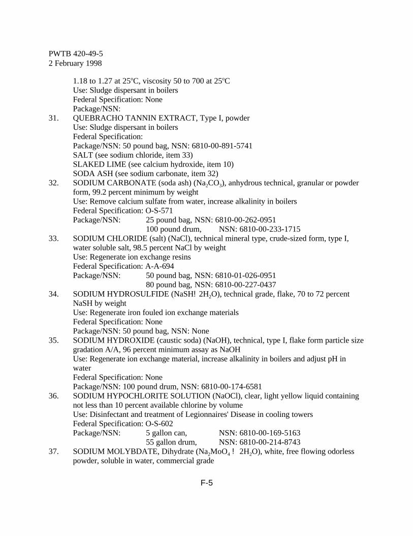
PWTB 420-49-52 February 1998
F-5
1.18 to 1.27 at 25oC, viscosity 50 to 700 at 25oCUse: Sludge dispersant in boilersFederal Specification: NonePackage/NSN:
31. QUEBRACHO TANNIN EXTRACT, Type I, powderUse: Sludge dispersant in boilersFederal Specification: Package/NSN: 50 pound bag, NSN: 6810-00-891-5741SALT (see sodium chloride, item 33)SLAKED LIME (see calcium hydroxide, item 10)SODA ASH (see sodium carbonate, item 32)
32. SODIUM CARBONATE (soda ash) (Na2CO3), anhydrous technical, granular or powderform, 99.2 percent minimum by weightUse: Remove calcium sulfate from water, increase alkalinity in boilersFederal Specification: O-S-571Package/NSN: 25 pound bag, NSN: 6810-00-262-0951
100 pound drum, NSN: 6810-00-233-171533. SODIUM CHLORIDE (salt) (NaCl), technical mineral type, crude-sized form, type I,
water soluble salt, 98.5 percent NaCl by weightUse: Regenerate ion exchange resinsFederal Specification: A-A-694Package/NSN: 50 pound bag, NSN: 6810-01-026-0951
80 pound bag, NSN: 6810-00-227-043734. SODIUM HYDROSULFIDE (NaSH!2H2O), technical grade, flake, 70 to 72 percent
NaSH by weightUse: Regenerate iron fouled ion exchange materialsFederal Specification: NonePackage/NSN: 50 pound bag, NSN: None
35. SODIUM HYDROXIDE (caustic soda) (NaOH), technical, type I, flake form particle sizegradation A/A, 96 percent minimum assay as NaOHUse: Regenerate ion exchange material, increase alkalinity in boilers and adjust pH inwaterFederal Specification: NonePackage/NSN: 100 pound drum, NSN: 6810-00-174-6581
36. SODIUM HYPOCHLORITE SOLUTION (NaOCl), clear, light yellow liquid containingnot less than 10 percent available chlorine by volumeUse: Disinfectant and treatment of Legionnaires' Disease in cooling towersFederal Specification: O-S-602Package/NSN: 5 gallon can, NSN: 6810-00-169-5163
55 gallon drum, NSN: 6810-00-214-874337. SODIUM MOLYBDATE, Dihydrate (Na2MoO4 ! 2H2O), white, free flowing odorless
powder, soluble in water, commercial grade

PWTB 420-49-52 February 1998
F-6
Use: Corrosion inhibitor for open cooling systemsFederal Specification: NonePackage/NSN: 200 pound lined fiber drum, NSN: None
38. SODIUM MOLYBDATE, solution, 35% as Na2MoO4, clear liquid, soluble in waterUse: Corrosion inhibitor for open cooling systemsFederal Specification: Package/NSN: 55 gallon drum, NSN:
39. SODIUM MOLYBDATE BLEND, Liquid, mixture of 10 to 12 percent sodiummolybdate (Na2MoO4), 3 to 5 percent sodium hydroxide (NaOH), and 3 to 4 percentcopper corrosion inhibitorUse: Corrosion control in hot water systems, chilled and brine systems, combined hot andchilled water systems, and diesel engine jacket cooling systems. Compatible with ethyleneglycol antifreeze.Federal Specification: NonePackage/NSN: 55 gallon drum, NSN: 6850-01-185-1188
40. SODIUM NITRITE (NaNO2), granular, 97 percent NO2 by weight, technical gradeUse: Corrosion control in hot water systemsFederal Specification: O-S-634Package/NSN: 100 pound drum, NSN: None
41. SODIUM NITRITE-BORAX BLEND, powdered or granular, a mixture of 65 to 70percent sodium nitrite, 8 to 12 percent borax (sodium tetraborate), 4 to 5 percent coppercorrosion inhibitor, and 15 to 20 percent sodium carbonate, free of excess foreign matterUse: Corrosion control in closed hot water systems. Compatible with ethylene glycolantifreeze.Federal Specification: NonePackage/NSN: 30 gallon can, NSN: 6850-01-185-1187
42. SODIUM SILICATE, relatively low alkalinity, 41o Baumé, approximately 28.8 percentSiO2, 6 to 7 percent Na2O, not more than 0.5 percent suspended matterUse: Cathodic corrosion inhibitor in cooling towersFederal Specification: O-S-605Package/NSN: 5 gallon can, NSN: 6810-00-247-0607
55 gallon drum, NSN: 6810-00-247-060943. SODIUM SULFITE, (Na2SO3), anhydrous, granular, 96 percent by weight minimum
Use: Remove oxygen from boiler feedwater and closed hot water systems (oxygenscavenger)Federal Specification: O-S-650Package/NSN: 100 pound bag, NSN: 6810-00-782-2677
44. SODIUM SULFITE, catalyzed with cobalt, granular, 95 percent by weight minimumUse: Remove oxygen from boiler feedwater (oxygen scavenger)Federal Specification: NonePackage/NSN: 50 pound bag, NSN: 6850-01-109-5604
45. SULFONATED STYRENE COPOLYMER, low molecular weight, clear amber color,total solids, 23 to 27 percent, pH of 6.8, molecular weight 5000 to 10000, specific gravity
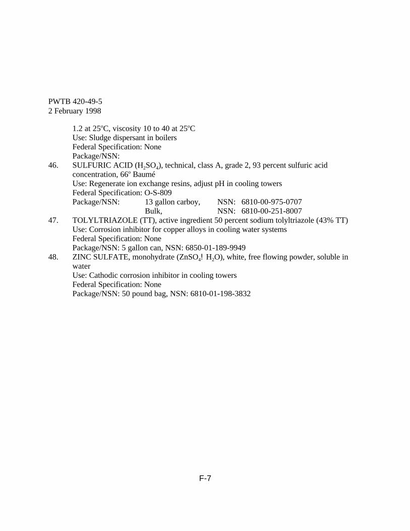
PWTB 420-49-52 February 1998
F-7
1.2 at 25oC, viscosity 10 to 40 at 25oCUse: Sludge dispersant in boilersFederal Specification: NonePackage/NSN:
46. SULFURIC ACID (H2SO4), technical, class A, grade 2, 93 percent sulfuric acidconcentration, 66o BauméUse: Regenerate ion exchange resins, adjust pH in cooling towersFederal Specification: O-S-809Package/NSN: 13 gallon carboy, NSN: 6810-00-975-0707
Bulk, NSN: 6810-00-251-800747. TOLYLTRIAZOLE (TT), active ingredient 50 percent sodium tolyltriazole (43% TT)
Use: Corrosion inhibitor for copper alloys in cooling water systemsFederal Specification: NonePackage/NSN: 5 gallon can, NSN: 6850-01-189-9949
48. ZINC SULFATE, monohydrate (ZnSO4!H2O), white, free flowing powder, soluble inwaterUse: Cathodic corrosion inhibitor in cooling towersFederal Specification: NonePackage/NSN: 50 pound bag, NSN: 6810-01-198-3832

PWTB 420-49-52 February 1998
G-1
GLOSSARY
ACID: A compound, usually having a sourtaste, which is able to neutralize an alkali orbase; a substance that dissolves in water witha formation of hydrogen ions.
AERATION: The bringing about ofintimate contact between air and liquid byone of the following methods: spraying theliquid in the air; bubbling air through theliquid; or by agitation of the liquid topromote surface absorption of air.
ALGAE: Tiny plant life, usuallymicroscopic, existing in water. They aremostly green, blue-green, or yellow-green,and are the cause of most tastes and odors inwater. They create suspended solids whenthey grow in an industrial water system.
ALKALINITY: (a) A term used torepresent the content of carbonates,bicarbonates, hydroxides, and occasionallyborates, silicates, and phosphates in water. (b) The capacity of water to react withhydrogen ions.
ALKALINITY, TOTAL OR MIXEDINDICATOR (M): A measure of the totalalkalinity of water. Measured by thequantity of 0.02 N sulfuric acid required tobring water to pH of 4.4, as indicated by thechange in color of methyl orange or a mixedindicator. Results are expressed in parts permillion (ppm) as calcium carbonate.
ALKALINITY, PHENOLPHTHALEIN(P): A measure of hydroxide ions (OH) plusone-half of the normal carbonates in water. Measured by the quantity of 0.02 N sulfuricacid required to bring the water to pH 8.2, asindicated by the decolorization of
phenolphthalein indicator. Results areexpressed in parts per million (ppm) ascalcium carbonate.
ALKALINITY, HYDROXYL: A measureof hydroxyl ion (OH-) contribution to thealkalinity. This is related to the system pHand also may be referred to as causticity.
BACKWASH: The reversal of flowthrough a filter or an ion exchanger to washclogging material out of the filtering mediumand reduce conditions causing loss of head.
BACKFLOW PREVENTOR: A devicefor a water supply pipe to prevent thebackflow of water into the water supplysystem from the system which it supplies.
BACTERIA: Simple single-cellmicroscopic organisms generally free ofpigment. They do not require light for theirlife processes.
BASE: An alkali or hydroxide of the alkalimetals and of ammonia. They can neutralizeacids to form salts and water. A base willionize to form hydroxyl ions (OH-).
BIOCIDES: Material typically used todestroy microorganisms (also calledmicrobiocides).
BIOLOGICAL DEPOSITS: Water-formed deposits of organisms or theproducts of their life processes. Biologicaldeposits may be composed of microscopicorganisms, as in slimes, or of macroscopicorganisms such as barnacles or mussels.BLOWDOWN: The action of draining aportion of water from a system to reduce the
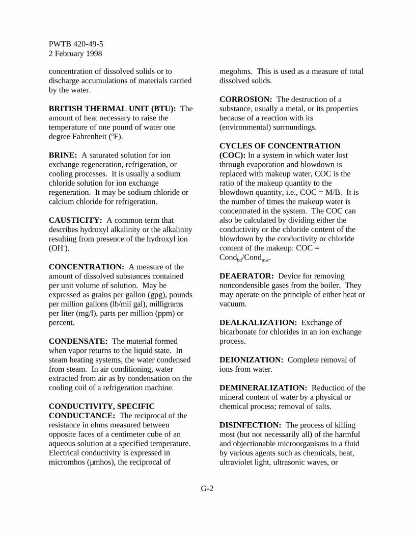
PWTB 420-49-52 February 1998
G-2
concentration of dissolved solids or todischarge accumulations of materials carriedby the water.
BRITISH THERMAL UNIT (BTU): Theamount of heat necessary to raise thetemperature of one pound of water onedegree Fahrenheit (oF).
BRINE: A saturated solution for ionexchange regeneration, refrigeration, orcooling processes. It is usually a sodiumchloride solution for ion exchangeregeneration. It may be sodium chloride orcalcium chloride for refrigeration.
CAUSTICITY: A common term thatdescribes hydroxyl alkalinity or the alkalinityresulting from presence of the hydroxyl ion(OH-).
CONCENTRATION: A measure of theamount of dissolved substances containedper unit volume of solution. May beexpressed as grains per gallon (gpg), poundsper million gallons (lb/mil gal), milligramsper liter (mg/l), parts per million (ppm) orpercent.
CONDENSATE: The material formedwhen vapor returns to the liquid state. Insteam heating systems, the water condensedfrom steam. In air conditioning, waterextracted from air as by condensation on thecooling coil of a refrigeration machine.
CONDUCTIVITY, SPECIFICCONDUCTANCE: The reciprocal of theresistance in ohms measured betweenopposite faces of a centimeter cube of anaqueous solution at a specified temperature. Electrical conductivity is expressed inmicromhos (µmhos), the reciprocal of
megohms. This is used as a measure of totaldissolved solids.
CORROSION: The destruction of asubstance, usually a metal, or its propertiesbecause of a reaction with its(environmental) surroundings.
CYCLES OF CONCENTRATION(COC): In a system in which water lostthrough evaporation and blowdown isreplaced with makeup water, COC is theratio of the makeup quantity to theblowdown quantity, i.e., COC = M/B. It isthe number of times the makeup water isconcentrated in the system. The COC canalso be calculated by dividing either theconductivity or the chloride content of theblowdown by the conductivity or chloridecontent of the makeup: COC =Condbd/Condmw.
DEAERATOR: Device for removingnoncondensible gases from the boiler. Theymay operate on the principle of either heat orvacuum.
DEALKALIZATION: Exchange ofbicarbonate for chlorides in an ion exchangeprocess.
DEIONIZATION: Complete removal ofions from water.
DEMINERALIZATION: Reduction of themineral content of water by a physical orchemical process; removal of salts.
DISINFECTION: The process of killingmost (but not necessarily all) of the harmfuland objectionable microorganisms in a fluidby various agents such as chemicals, heat,ultraviolet light, ultrasonic waves, or
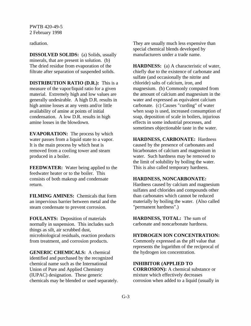
PWTB 420-49-52 February 1998
G-3
radiation.
DISSOLVED SOLIDS: (a) Solids, usuallyminerals, that are present in solution. (b)The dried residue from evaporation of thefiltrate after separation of suspended solids.
DISTRIBUTION RATIO (D.R.): This is ameasure of the vapor/liquid ratio for a givenmaterial. Extremely high and low values aregenerally undesirable. A high D.R. results inhigh amine losses at any vents and/or littleavailability of amine at points of initialcondensation. A low D.R. results in highamine losses in the blowdown.
EVAPORATION: The process by whichwater passes from a liquid state to a vapor. It is the main process by which heat isremoved from a cooling tower and steamproduced in a boiler.
FEEDWATER: Water being applied to thefeedwater heater or to the boiler. Thisconsists of both makeup and condensatereturn.
FILMING AMINES: Chemicals that forman impervious barrier between metal and thesteam condensate to prevent corrosion.
FOULANTS: Deposition of materialsnormally in suspension. This includes suchthings as silt, air scrubbed dust,microbiological residuals, reaction productsfrom treatment, and corrosion products.
GENERIC CHEMICALS: A chemicalidentified and purchased by the recognizedchemical name such as the InternationalUnion of Pure and Applied Chemistry(IUPAC) designation. These genericchemicals may be blended or used separately.
They are usually much less expensive thanspecial chemical blends developed bymanufacturers under a trade name.
HARDNESS: (a) A characteristic of water,chiefly due to the existence of carbonate andsulfate (and occasionally the nitrite andchloride) salts of calcium, iron, andmagnesium. (b) Commonly computed fromthe amount of calcium and magnesium in thewater and expressed as equivalent calciumcarbonate. (c) Causes "curding" of waterwhen soap is used, increased consumption ofsoap, deposition of scale in boilers, injuriouseffects in some industrial processes, andsometimes objectionable taste in the water.
HARDNESS, CARBONATE: Hardnesscaused by the presence of carbonates andbicarbonates of calcium and magnesium inwater. Such hardness may be removed tothe limit of solubility by boiling the water. This is also called temporary hardness.
HARDNESS, NONCARBONATE: Hardness caused by calcium and magnesiumsulfates and chlorides and compounds otherthan carbonates which cannot be reducedmaterially by boiling the water. (Also called"permanent hardness".)
HARDNESS, TOTAL: The sum ofcarbonate and noncarbonate hardness.
HYDROGEN ION CONCENTRATION: Commonly expressed as the pH value thatrepresents the logarithm of the reciprocal ofthe hydrogen ion concentration.
INHIBITOR (APPLIED TOCORROSION): A chemical substance ormixture which effectively decreasescorrosion when added to a liquid (usually in

PWTB 420-49-52 February 1998
G-4
small concentrations).
ION: A particle, atom or group of atoms,carrying either a positive or negativeelectrical charge which is formed when anelectrolyte is dissolved in water.
ION EXCHANGE: A process where wateris passed through a granular material andions on the granular material are replaced byions contained in the water. For example, inthe zeolite softening process, the sodiumions (Na+) of the granular zeolite arereplaced by the calcium ions (Ca++) in thewater to leave the water free of calcium (thecause of hardness), but with an increasedamount of sodium.
LANGELIER INDEX (SATURATIONINDEX): An index based on the calciumhardness, total alkalinity, total dissolvedsolids, temperature, and pH. It classifieswaters as to their ability to dissolve ordeposit calcium carbonate. It is the algebraicdifference between the actual pH and thecalculated pH of saturation (pHs). LI = pH -pHs. A positive value indicates a scaleforming tendency, a negative value indicatesa scale dissolving tendency. It was one ofthe first indices developed for this purposeand was designed specifically for municipalwater flowing in distribution lines.
MAKEUP WATER: Water supplied toreplace the loss in a system by leaks,evaporation, wind drift, bleedoff, blowdown,or withdrawal.
MICROBIOCIDE: A material added tocooling tower water and to chilled water tocontrol the growths of microorganisms suchas algae, bacteria, and fungi.
MICROMHO: An electrical unit ofconductance (one millionth of a mho) whichis the reciprocal of electrical resistance.
MICROORGANISM: A minute plant oranimal in water or earth that is visible onlythrough a microscope.
MILLIGRAMS PER LITER (mg/l): Aunit of the concentration of water orwastewater constituent. It is 0.001 gram ofthe constituent in 1,000 milliliters of water. It has replaced the parts per million (ppm)unit, to which it is approximately equivalent,in reporting the results of water andwastewater analyses.
NEUTRALIZING AMINES: Chemicalsused to neutralize carbon dioxide in steamcondensate to prevent corrosion.
NORMALITY: The concentration of asolution in relation to a normal solution. Thenormal solution contains a specific weight ofa substance per liter based on thecharacteristics of the substance. Thus, ahalf-normal solution would be expressed as0.5 N or N/2.
OXYGEN SCAVENGER: A chemicalused to remove final traces of oxygen from aboiler feedwater.
pH: Measure of hydrogen ion concentrationindicating degrees of acidity or alkalinity of asolution. The range pH varies from 1 to 14. Values below 7.0 indicate acidity and above7.0, alkalinity.
pHeq: The pH of equilibrium. The adjustedpH of a water based on the empiricalrelationship between total alkalinity and pHdeveloped from studies of hundreds of

PWTB 420-49-52 February 1998
G-5
cooling systems. This is necessary becausepH in cooling waters is often buffered, whichaffects the relationship between pH andbicarbonate alkalinity.
pHs: The pH of saturation. It is the pHbelow which a material will go into solutionand above which it will precipitate. It is usedfor calcium carbonate in the Langelier,Ryznar, and Practical Scaling Indices. It is afunction of the calcium hardness, the totalalkalinity, the total dissolved solids and thetemperature. It is determined with graphs,tables, or special slide rules. This equation isuseful:pHs = 12.27 - 0.00915T - log CaH - log TA
+ (log TDS)/10
PHOSPHATES: Chemicals used forcorrosion control in cooling towers and fordeposit control in boilers. Commonly theseoccur as orthophosphates or polyphosphates. The level of the active phosphate chemical isreported either as percent P2O5 (phosphoruspentoxide) or as PO4 (phosphate) with theserelated by factor as follows: PO4 = 1.34 xP2O5.
ppm: Parts per million; one pound ofmaterial dissolved in one million pounds ofwater.
PRECIPITATE: (a) To separate asubstance in the solid form from a solution. (b) The substance in solid form which hasbeen separated from solution.
PRACTICAL SCALING INDEX (PSI): A modified scaling index developed by P.R.Puckorius and J.M. Brooke to provide abetter and more consistent indication ofscaling conditions of cooling water. It isbased on using the pH of equilibrium (pHeq)
rather than the actual pH, and is calculatedas follows: PSI = 2 pHs - pHeq. As with theRSI, a value less than 6.0 in natural waterindicates a scale forming tendency. A valuegreater than 6.0 in natural water indicates ascale dissolving tendency.
REGENERATION: That part of theoperating cycle of an ion exchange process inwhich a specific chemical solution is passedthrough the ion exchange bed to prepare itfor a service run.
RYZNAR INDEX (STABILITY INDEX): An index classifying waters as to their abilityto dissolve or deposit calcium carbonatescale. It is twice the pH of saturation minusthe actual pH (RI = 2 pHs - pH). Althoughin theory an RI of 7.0 should be neutral,experiments indicate that 6.0 is a bettervalue. A value less than 6.0 in natural waterindicates a scale forming tendency. A valuegreater than 6.0 in natural water indicates ascale dissolving tendency.
SCALE: Deposition on a heat transfersurface of normally soluble salts. Scale isusually crystalline and dense, frequentlylaminated, and occasionally columnar instructure.
SLIME: Biological growths that mayaccumulate to the extent that they foulequipment.
SLUDGE: A water-formed deposit that willsettle and may include all suspended solidscarried by water. Sludge is commonlyformed in boilers where it may be baked intoplace and become hard and adherent.
SOFTENING WATER: The process ofremoving from water certain mineral
PWTB 420-49-52 February 1998
G-6
substances which produce a condition calledhardness. There are two softening processesin general use: chemical precipitation (limeand lime/soda softening) and the zeolite ionexchange process.
SOLIDS, SUSPENDED: All matter inwater which is not dissolved and which canbe removed with filtration.
SOLIDS, DISSOLVED: The totalconcentration of all substances in a filteredsolution which exist as solids after the liquidis completely evaporated from the solution.
SOLIDS, TOTAL: The sum of thesuspended and dissolved matter (solids).
ZEOLITE: Natural minerals as well assynthetic resins used for ion exchange.