PW130ES-6K - Fermer.Ru
271
PW130ES-6K SERIAL NUMBER PW130ES-6K - K34001 and up HYDRAULIC EXCAVATOR Unsafe use of this machine may cause serious injury or death. Operators and maintenance personnel must read this manual before operating or maintaining this machine. This manual should be kept inside the cab for reference and periodically reviewed by all personel who will come into contact with the machine. Operation & Maintenance Manual UEAM000902 WARNING
Transcript of PW130ES-6K - Fermer.Ru

PW130ES-6K
SERIAL NUMBER PW130ES-6K - K34001 and up
HYDRAULIC EXCAVATOR
Unsafe use of this machine may cause serious injury ordeath. Operators and maintenance personnel must readthis manual before operating or maintaining thismachine. This manual should be kept inside the cab forreference and periodically reviewed by all personel whowill come into contact with the machine.
Operation & Maintenance Manual
UEAM000902
WARNING

FOREWORD
FOREWORD
This manual provides rules and guidelines which will help you use this machine safely and effectively. Keep thismanual handy and have all personnel read it periodically. If this manual has been lost or has become dirty and cannot be read, request a replacement manual from Komatsu or your Komatsu distributor.
If you sell the machine, be sure to give this manual to the new owners.
Continuing improvements in the design of this machine can lead to changes in detail which may not be reflected inthis manual. Consult Komatsu or your Komatsu distributor for the latest available information for your machine orfor questions regarding information in this manual.
WARNING
� This operation & maintenance manual may containattachments and optional equipment that are not avail-able in your area. Please consult your local Komatsu dis-tributor for those items you require.
� This machine complies with EC directive (89/392/EEC).Machines complying with this directive display the CEmark
� Improper operation and maintenance of this machine canbe hazardous and could result in serious injury or death.
� Operators and maintenance personnel should read thismanual thoroughly before beginning operation or main-tenance.
� Some actions involved in operation and maintenance ofthe machine can cause a serious accident, if they are notdone in a manner described in this manual.
� The procedures and precautions given in this manualapply only to intended uses of the machine. If you useyour machine for any unintended uses that are not spe-cifically prohibited, you must be sure that it is safe foryou and others. In no event should you or others engagein prohibited uses or actions as described in this manual.
� Komatsu delivers machines that comply with all applica-ble regulations and standards of the country to which ithas been shipped. If this machine has been purchased inanother country or purchased from someone in anothercountry, it may lack certain safety devices and specifica-tions that are necessary for use in your country. If thereis any question about whether your product complieswith the applicable standards and regulations of yourcountry, consult Komatsu or your Komatsu distributorbefore operating the machine.
� The description of safety is given see “SAFETY INFOR-MATION” on page 2. and in "SAFETY" from page 15.
1

SAFETY INFORMATION
SAFETY INFORMATION
SAFETY MESSAGESMost accidents are caused by the failure to follow fundamentalsafety rules for the operation and maintenance of machines.
To avoid accidents, read, understand and follow all precautionsand warnings in this manual and on the machine before perform-ing operation and maintenance.
To identify hazards on the machine pictorial decals are used (seePOSITION FOR ATTACHING SAFETY LABELS).
RED WARNING TRIANGLE - This is used on safetylabels where there is a high probability of serious injury or death ifthe hazard is not avoided. These safety messages or labels usu-ally describe precautions that must be taken to avoid the hazard.Failure to avoid this hazard may also result in serious damage tothe machine.
ORANGE WARNING TRIANGLE - This is used onsafety labels where there is a potentially dangerous situationwhich could result in serious injury or death if the hazard is notavoided. These safety messages or labels usually describe pre-cautions that must be taken to avoid the hazard. Failure to avoidthis hazard may also result in serious damage of the machine
YELLOW SAFETY TRIANGLE - This is used onsafety labels for hazards which could result in minor or moderateinjury if the hazard is not avoided. This word might also be usedfor a hazard where the only result could be damage to themachine.
NOTICE - This word is used for precautions that must be taken toavoid actions which could shorten the life of the machine.
Safety precautions are described in SAFETY from page 1-1.
Komatsu cannot predict every circumstance that might involve apotential hazard in operation and maintenance. Therefore thesafety message in this manual and on the machine may notinclude all possible safety precautions. If any procedures oractions not specifically recommended or allowed in this manualare used, you must be sure that you and others can do such pro-cedures and actions safely and without damaging the machine. Ifyou are unsure about the safety of some procedures, contactKomatsu or your Komatsu distributor.
2

SAFETY INFORMATION
NOISEValid until 31 December 2001
Operator ears noise value (Sound pressure level)
Ambient noise value (Sound power level)
Noise level indicated is the guaranteed value measured by thedynamic test method as specified in the directive 86/662/EEC, asamended by 95/27/EC.
LpA
95/27/EC
75
LWA
95/27/EC
99
3

SAFETY INFORMATION
Valid as of 1 January 2002
� Sound pressure level at the operator's station, measuredaccording to ISO6396 (Dynamic test method, simulated work-ing cycle)
� Sound power level emitted. This is the guaranteed value asspecified in European directive 2000/14/EC.
This machine complies with the requirements of RAL (GermanInstitute for quality assurance and marking) pertaining to theaward of the environmental mark (blue angel) for low noise.
VIBRATION� The weighted root mean square acceleration value to which
the operator’s arms are subjected does not exceed 2.5 m/s²
� The weighted root mean square acceleration value to whichthe operator’s body is subjected was measured at 0.64 m/s²
4

SAFETY INFORMATION
These results were obtained by accelerometers during trench dig-ging.
EMERGENCY STEERINGThis machine is equipped with an emergency steering systemand complies to ISO 5010. In the advent of failure of the source ofpower for the steering system (engine failure) whilst travelling themachine can be steered allowing the machine to be safelystopped.
In such a case the effort required at the steering wheel and thenumber of turns to steer the machine will increase. To confirmfunction of emergency steering system raise the front wheels offthe ground (using the work equipment) and with the engine off,turn the steering wheel and check movement of the wheels.
5

INTRODUCTION
INTRODUCTION
INTENDED USEThis Komatsu HYDRAULIC EXCAVATOR is designed to be usedmainly for the following work:
� Digging
� Smoothing work
� Ditching work
� Loading work
See the section “WORK POSSIBLE USING HYDRAULICEXCAVATOR” on page 132 for further details
Features� This Komatsu HYDRAULIC EXCAVATOR is equipped with
various controls based on an advanced electronics system.
� The monitor panel greatly facilitates daily maintenance andself-diagnosis.
� Working mode & travel speed are selectable.
� Digging and lifting force can be increased by light-touch con-trol. (For details, see operation section.)
� Adjustable wrist control levers make operations smooth andeasy.
� Fresh filtered air conditioner assures comfortable operation.
� Low noise level and smart urban style design and colouring.
� Superb operation performance provided by powerful engineand high-performance hydraulic pump.
� Low fuel consumption controlled by an electronic control sys-tem provides an environment-friendly machine.
BREAKING IN YOUR NEW MACHINEYour Komatsu machine has been thoroughly adjusted and testedbefore shipment.
However, operating the machine under severe conditions at thebeginning can adversely affect the performance and shorten themachine life.
Be sure to break in the machine for the initial 100 hours (as indi-cated by the hour meter.)
During breaking in:
6

INTRODUCTION
� Idle the engine for 5 minutes after starting it up.
� Avoid operation with heavy loads or at high speeds.
� Sudden starting or acceleration, unnecessarily abrupt brakingand sharp turning should be avoided except in cases of emer-gency.
Additionally for the first 20 hours
� Avoid operating engine for prolonged periods at constantspeed (including idle.)
� Avoid high speed travelling for periods of more than 5 min-utes.
Pay particular attention to oil pressure and temperature indicators& check coolant and oil levels frequently during breaking in.
The precautions given in this manual for operating, maintenance,and safety procedures are only those that apply when this productis used for the specified purpose. If the machine is used for a pur-pose that is not listed in this manual, Komatsu cannot bear anyresponsibility for safety. All consideration of safety in such opera-tions is the responsibility of the user.
Operations that are prohibited in this manual must never be car-ried out under any circumstances.
7

LOCATIONS OF PLATES, TABLE TO ENTER SERIAL NO. AND DISTRIBUTOR
LOCATIONS OF PLATES, TABLE TO ENTER SERIAL NO. AND DISTRIBUTOR
MACHINE SERIAL NO. PLATE POSITIONOn the front right of the undercarriage
ENGINE SERIAL NO. PLATE POSITIONOn the gear case front corner.
TABLE TO ENTER SERIAL NO. AND DISTRIBUTORMachine serial No.:
Engine Serial No.:
Manufacturer’s name: Komatsu UK Ltd.
Address
Durham RoadBirtleyChester-Le-StreetCounty Durham DH32QXUnited Kingdom
Distributor
Address
Phone
8

LOCATIONS OF PLATES, TABLE TO ENTER SERIAL NO. AND DISTRIBUTOR
MACHINE SERIAL PLATES
STANDARD SERIAL PLATE
GERMANY SERIAL PLATE
ITALIAN SERIAL PLATE
9

LOCATIONS OF PLATES, TABLE TO ENTER SERIAL NO. AND DISTRIBUTOR
10

CONTENTS
FOREWORD ........................................................................................................................................................... 1
SAFETY INFORMATION ........................................................................................................................................ 2SAFETY MESSAGES ................................................................................................................................... 2NOISE ........................................................................................................................................................... 3VIBRATION ................................................................................................................................................... 4EMERGENCY STEERING ........................................................................................................................... 5
INTRODUCTION ..................................................................................................................................................... 6INTENDED USE ........................................................................................................................................... 6Features ........................................................................................................................................................ 6BREAKING IN YOUR NEW MACHINE ........................................................................................................ 6
LOCATIONS OF PLATES, TABLE TO ENTER SERIAL NO. AND DISTRIBUTOR ............................................. 8MACHINE SERIAL NO. PLATE POSITION .................................................................................................. 8ENGINE SERIAL NO. PLATE POSITION .................................................................................................... 8TABLE TO ENTER SERIAL NO. AND DISTRIBUTOR ................................................................................ 8MACHINE SERIAL PLATES ......................................................................................................................... 9
SAFETY............................................................................................................. 15
GENERAL PRECAUTIONS ................................................................................................................................. 16
PRECAUTION DURING OPERATION ................................................................................................................. 22BEFORE STARTING ENGINE ................................................................................................................... 22OPERATING MACHINE ............................................................................................................................. 23TRANSPORTATION ................................................................................................................................... 28BATTERY ................................................................................................................................................... 29TOWING ..................................................................................................................................................... 30BUCKET WITH HOOK OR BUCKET LINK ................................................................................................. 32
PRECAUTIONS FOR MAINTENANCE ................................................................................................................ 35BEFORE CARRYING OUT MAINTENANCE ............................................................................................. 35DURING MAINTENANCE ........................................................................................................................... 38
POSITION FOR ATTACHING SAFETY LABELS ................................................................................................ 41POSITION FOR ATTACHING SAFETY LABELS ....................................................................................... 41
OPERATION....................................................................................................... 55
GENERAL VIEW .................................................................................................................................................. 56GENERAL VIEW OF MACHINE ................................................................................................................. 56 .................................................................................................................................................................... 56GENERAL VIEW OF CONTROLS AND GAUGES ..................................................................................... 57
11

EXPLANATION OF COMPONENTS .................................................................................................................... 59MACHINE MONITOR ................................................................................................................................. 59SWITCHES ................................................................................................................................................. 70CONTROL LEVERS, PEDALS ................................................................................................................... 80ROOF HATCH ............................................................................................................................................ 83FRONT WINDOW ....................................................................................................................................... 85DOOR LOCK .............................................................................................................................................. 88CAP, COVER WITH LOCK ......................................................................................................................... 89FUSE .......................................................................................................................................................... 90LUGGAGE TRAY ........................................................................................................................................ 91ASHTRAY ................................................................................................................................................... 91HEATER ..................................................................................................................................................... 91AIR CONDITIONER .................................................................................................................................... 93FUSIBLE LINK ............................................................................................................................................ 96CONTROLLERS ......................................................................................................................................... 96TOOL BOX .................................................................................................................................................. 96REFUELLING PUMP .................................................................................................................................. 96CAB RADIO (OPTION) ............................................................................................................................... 97WARNING LAMPS ..................................................................................................................................... 98HANDLING THE ACCUMULATOR ............................................................................................................ 99
OPERATION ....................................................................................................................................................... 101CHECK BEFORE STARTING ENGINE .................................................................................................... 101STARTING ENGINE ................................................................................................................................. 110MOVING MACHINE OFF .......................................................................................................................... 119STEERING ................................................................................................................................................ 121STOPPING ............................................................................................................................................... 123SWINGING (Slewing the upper carriage) ................................................................................................. 124OPERATION OF WORK EQUIPMENT .................................................................................................... 125WORKING MODE SELECTION ............................................................................................................... 126PROHIBITIONS FOR OPERATION ......................................................................................................... 128PRECAUTIONS FOR OPERATION ......................................................................................................... 129PRECAUTIONS WHEN TRAVELING UP OR DOWN HILLS ................................................................... 130HOW TO ESCAPE FROM MUD ............................................................................................................... 131WORK POSSIBLE USING HYDRAULIC EXCAVATOR ........................................................................... 132REPLACEMENT AND INVERSION OF BUCKET .................................................................................... 133PARKING MACHINE ................................................................................................................................ 136CHECK AFTER FINISHING WORK ......................................................................................................... 137STOPPING ENGINE ................................................................................................................................. 137CHECK AFTER STOPPING ENGINE ...................................................................................................... 138LOCKING .................................................................................................................................................. 138OVERLOAD WARNING DEVICE ............................................................................................................. 138HANDLING THE WHEELS ....................................................................................................................... 138
TRANSPORTATION ........................................................................................................................................... 144LOADING, UNLOADING WORK .............................................................................................................. 144PRECAUTIONS FOR LOADING .............................................................................................................. 146PRECAUTIONS FOR TRANSPORTATION ............................................................................................. 148
12

TRAVELLING POSTURE ......................................................................................................................... 149
COLD WEATHER OPERATION ........................................................................................................................ 150PRECAUTIONS FOR LOW TEMPERATURE .......................................................................................... 150PRECAUTIONS AFTER COMPLETION OF WORK ................................................................................ 151AFTER COLD WEATHER ........................................................................................................................ 152
LONG-TERM STORAGE .................................................................................................................................... 153BEFORE STORAGE ................................................................................................................................. 153DURING STORAGE ................................................................................................................................. 153AFTER STORAGE .................................................................................................................................... 154STARTING MACHINE AFTER LONG-TERM STORAGE ........................................................................ 154
TROUBLESHOOTING ........................................................................................................................................ 155PHENOMENA THAT ARE NOT FAILURES ............................................................................................. 155METHOD OF TOWING MACHINE ........................................................................................................... 156PRECAUTIONS ON PARTICULAR JOBSITES ....................................................................................... 156IF BATTERY IS DISCHARGED ................................................................................................................ 157OTHER TROUBLE ................................................................................................................................... 159
MAINTENANCE. .............................................................................................. 163
GUIDES TO MAINTENANCE ............................................................................................................................. 164
OUTLINES OF SERVICE ................................................................................................................................... 167OUTLINE OF OIL, FUEL, COOLANT ....................................................................................................... 167OUTLINE OF ELECTRIC SYSTEM .......................................................................................................... 170OUTLINE OF HYDRAULIC SYSTEM ....................................................................................................... 170
WEAR PARTS LIST ........................................................................................................................................... 172
USE FUEL, COOLANT AND LUBRICANTS ACCORDING TO AMBIENT TEMPERATURE .......................... 173PROPER SELECTION OF FUEL, COOLANT AND LUBRICANTS ......................................................... 173
STANDARD TIGHTENING TORQUES FOR BOLTS AND NUTS ..................................................................... 177INTRODUCTION OF NECESSARY TOOLS ............................................................................................ 177TORQUE LIST .......................................................................................................................................... 178
PERIODIC REPLACEMENT OF SAFETY CRITICAL PARTS .......................................................................... 179SAFETY CRITICAL PARTS ...................................................................................................................... 180
MAINTENANCE SCHEDULE CHART ............................................................................................................... 181 .................................................................................................................................................................. 181MAINTENANCE WHEN USING HYDRAULIC BREAKER ....................................................................... 186
SERVICE PROCEDURE .................................................................................................................................... 187INITIAL 250 HOURS SERVICE ................................................................................................................ 187WHEN REQUIRED ................................................................................................................................... 188CHECK BEFORE STARTING .................................................................................................................. 200
13

EVERY 50 HOURS ................................................................................................................................... 204EVERY 100 HOURS SERVICE ................................................................................................................ 204EVERY 250 HOURS SERVICE ................................................................................................................ 209EVERY 500 HOURS SERVICE ................................................................................................................ 215EVERY 1000 HOURS SERVICE .............................................................................................................. 221EVERY 2000 HOURS SERVICE .............................................................................................................. 225EVERY 4000 HOURS SERVICE .............................................................................................................. 228EVERY 5000 HOURS SERVICE .............................................................................................................. 228
SPECIFICATIONS............................................................................................ 231
SPECIFICATIONS .............................................................................................................................................. 232
OPTIONS, ATTACHMENTS ............................................................................ 237
GENERAL PRECAUTIONS ............................................................................................................................... 238PRECAUTIONS RELATED TO SAFETY ................................................................................................. 238PRECAUTIONS WHEN INSTALLING ATTACHMENTS .......................................................................... 239
HANDLING BUCKET WITH HOOK ................................................................................................................... 240CHECKING FOR DAMAGE TO BUCKET WITH HOOK .......................................................................... 240PROHIBITED OPERATIONS ................................................................................................................... 240PRECAUTIONS DURING OPERATIONS ................................................................................................ 240
MACHINES READY FOR ATTACHMENTS ...................................................................................................... 241GENERAL LOCATIONS ........................................................................................................................... 241HANDLING THE CLAMSHELL BUCKET ................................................................................................. 243OPERATION ............................................................................................................................................. 244HANDLING ACCUMULATOR ................................................................................................................... 246LONG-TERM STORAGE .......................................................................................................................... 247
INTRODUCTION OF ATTACHMENTS AND EXTENDING MACHINE SERVICE LIFE .................................... 248HYDRAULIC BREAKER ........................................................................................................................... 248POWER RIPPER ...................................................................................................................................... 251FORK GRAB ............................................................................................................................................. 252GRAPPLE BUCKET ................................................................................................................................. 253SCRAP GRAPPLE .................................................................................................................................... 254CRUSHER & SMASHER .......................................................................................................................... 256HYDRAULIC PILE DRIVER ...................................................................................................................... 257HYDRAULIC EXCAVATOR WITH MULTIPURPOSE CRANE ................................................................. 258ROTATING ARM ...................................................................................................................................... 260
14

SAFETY
WARNING
Read and follow all safety precautions. Failure to do so mayresult in serious injury or death.
This safety section also contains precautions for optional equip-ment and attachments.
15

GENERAL PRECAUTIONS SAFETY
WARNING: For reasons of safety, always follow these safety precautions.
GENERAL PRECAUTIONS
SAFETY RULES
� ONLY trained and authorised personnel can operate andmaintain the machine.
� Follow all safety rules, precautions and instructions whenoperating or performing maintenance on the machine.
� When working with another operator or a person on worksitetraffic duty, be sure all personnel understand all hand signalsthat are to be used.
SAFETY FEATURES
� Be sure all guards and covers are in their proper position.Have guards and covers repaired if damaged.
� Use safety features such as safety lock lever properly.
� NEVER remove any safety features. ALWAYS keep them ingood operating condition.
Safety lever see “PARKING MACHINE” on page 136.
� Improper use of safety features could result in serious bodilyinjury or death.
CLOTHING AND PERSONAL PROTECTIVE ITEMS
� Avoid loose clothing, jewellery, and loose long hair. They cancatch on controls or in moving parts and cause serious injuryor death. Also, do not wear oily cloths because they are flam-mable.
� Wear a hard hat, safety glasses, safety shoes, mask orgloves when operating or maintaining the machine. Alwayswear safety goggles, hard hat and heavy gloves if your jobinvolves scattering metal chips or minute materials, this is soparticularly when driving pins with a hammer and when clean-ing the air cleaner element with compressed air.Check also that there is no one near the machine.
Driving in pins, see “REPLACEMENT AND INVERSIONOF BUCKET” on page 133.
Cleaning of air cleaner element, see “WHEN REQUIRED”on page 188. in service procedure.
UNAUTHORISED MODIFICATION
� Any modification made without authorisation from Komatsucan create hazards.
16
SAFETY GENERAL PRECAUTIONS
WARNING: Failure to follow these safety precautions may lead to a serious accident.
� Before making a modification, consult your Komatsu distribu-tor. Komatsu will not be responsible for any injury or damagecaused by any unauthorised modification.
ALWAYS APPLY LOCK WHEN LEAVING OPERATOR’S SEAT
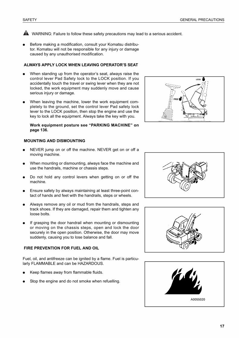
� When standing up from the operator’s seat, always raise thecontrol lever Pad Safety lock to the LOCK position. If youaccidentally touch the travel or swing lever when they are notlocked, the work equipment may suddenly move and causeserious injury or damage.
� When leaving the machine, lower the work equipment com-pletely to the ground, set the control lever Pad safety locklever to the LOCK position, then stop the engine and use thekey to lock all the equipment. Always take the key with you.
Work equipment posture see “PARKING MACHINE” onpage 136.
MOUNTING AND DISMOUNTING
� NEVER jump on or off the machine. NEVER get on or off amoving machine.
� When mounting or dismounting, always face the machine anduse the handrails, machine or chassis steps.
� Do not hold any control levers when getting on or off themachine.
� Ensure safety by always maintaining at least three-point con-tact of hands and feet with the handrails, steps or wheels.
� Always remove any oil or mud from the handrails, steps andtrack shoes. If they are damaged, repair them and tighten anyloose bolts.
� If grasping the door handrail when mounting or dismountingor moving on the chassis steps, open and lock the doorsecurely in the open position. Otherwise, the door may movesuddenly, causing you to lose balance and fall.
FIRE PREVENTION FOR FUEL AND OIL
Fuel, oil, and antifreeze can be ignited by a flame. Fuel is particu-larly FLAMMABLE and can be HAZARDOUS.
� Keep flames away from flammable fluids.
� Stop the engine and do not smoke when refuelling.
17

GENERAL PRECAUTIONS SAFETY
WARNING: For reasons of safety, always follow these safety precautions.
� Tighten all fuel and oil caps securely.
� Refuelling and oiling should be carried out in well ventilatedareas.
� Keep oil and fuel in a secure place and do not allow unautho-rised persons to enter.
PRECAUTIONS WHEN HANDLING AT HIGH TEMPERA-TURES
� Immediately after operations are stopped, the engine coolant,engine oil, and hydraulic oil are at high temperatures, and arestill under pressure. Attempting to remove the cap, drain theoil or water, or replace the filters may lead to serious burns.Always wait for the temperature to go down, and follow thespecified procedures when carrying out these operations.
� To prevent hot water from spurting out:
1. Turn engine off.
2. Allow water to cool.
3. Slowly loosen cap to relieve pressure before removing.
� To prevent hot oil from spurting out:
1. Turn engine off.
2. Allow oil to cool.
3. Slowly loosen cap to relieve pressure before removing.
MACHINES FITTED WITH WHEELS
Never perform any repair work or modifications to wheel rimswhile the tyres are fitted, and never apply heat in the vicinity onthe tyres
18
SAFETY GENERAL PRECAUTIONS
WARNING: Failure to follow these safety precautions may lead to a serious accident.
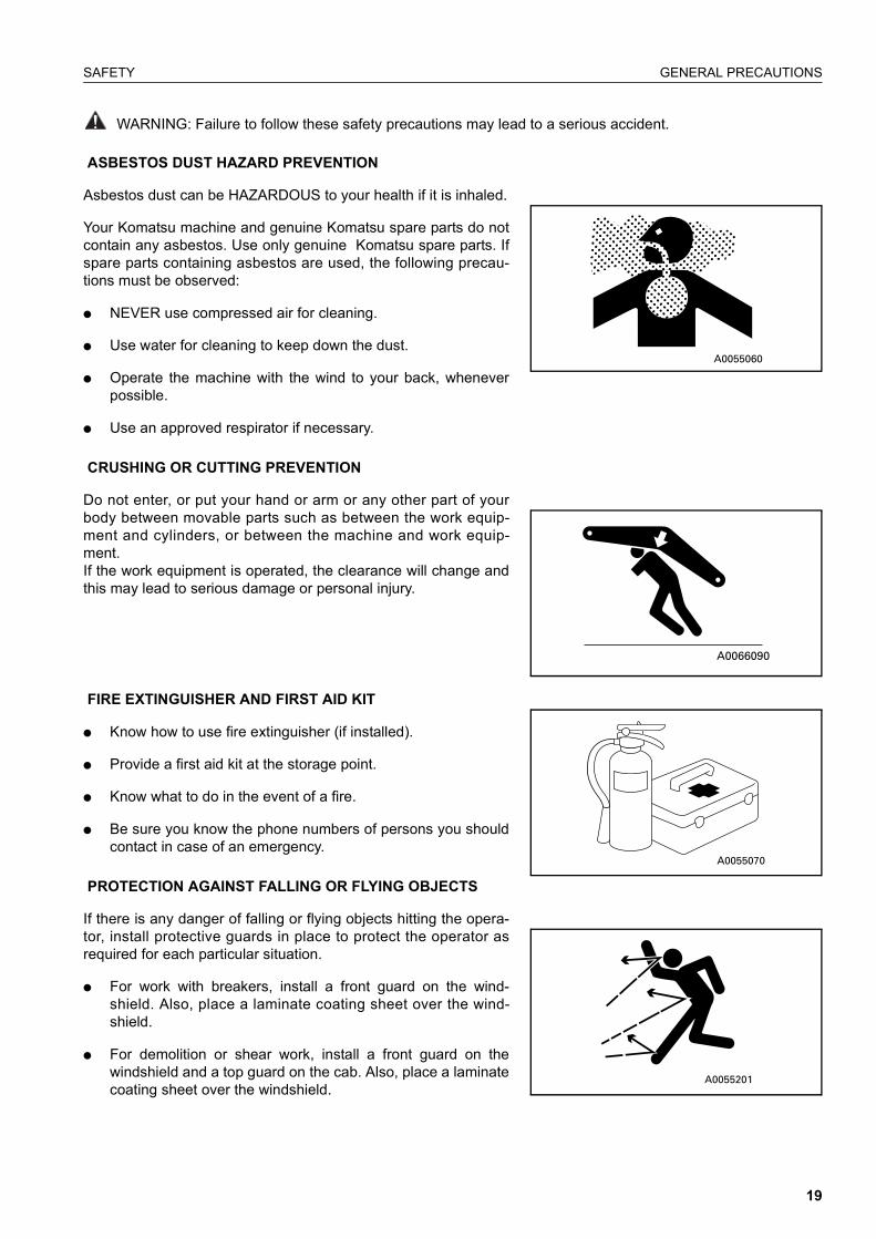
ASBESTOS DUST HAZARD PREVENTION
Asbestos dust can be HAZARDOUS to your health if it is inhaled.
Your Komatsu machine and genuine Komatsu spare parts do notcontain any asbestos. Use only genuine Komatsu spare parts. Ifspare parts containing asbestos are used, the following precau-tions must be observed:
� NEVER use compressed air for cleaning.
� Use water for cleaning to keep down the dust.
� Operate the machine with the wind to your back, wheneverpossible.
� Use an approved respirator if necessary.
CRUSHING OR CUTTING PREVENTION
Do not enter, or put your hand or arm or any other part of yourbody between movable parts such as between the work equip-ment and cylinders, or between the machine and work equip-ment.If the work equipment is operated, the clearance will change andthis may lead to serious damage or personal injury.
FIRE EXTINGUISHER AND FIRST AID KIT
� Know how to use fire extinguisher (if installed).
� Provide a first aid kit at the storage point.
� Know what to do in the event of a fire.
� Be sure you know the phone numbers of persons you shouldcontact in case of an emergency.
PROTECTION AGAINST FALLING OR FLYING OBJECTS
If there is any danger of falling or flying objects hitting the opera-tor, install protective guards in place to protect the operator asrequired for each particular situation.
� For work with breakers, install a front guard on the wind-shield. Also, place a laminate coating sheet over the wind-shield.
� For demolition or shear work, install a front guard on thewindshield and a top guard on the cab. Also, place a laminatecoating sheet over the windshield.
19

GENERAL PRECAUTIONS SAFETY
WARNING: For reasons of safety, always follow these safety precautions.
� For work in mines, quarries, demolition, tunnels or otherplaces where there is danger of falling rocks, put FOPS (fall-ing object protective structure) in place. Also, place a lami-nate coating sheet over the windshield.
The above comments are made with regards to typical workingconditions. By all means you should put on other guards ifrequired by conditions at your particular site.For details of safety guards, please contact your Komatsu distrib-utor.
Also, even for other types of work, if there is any danger of beinghit by falling or flying objects or of objects entering the operator’scab, select and install a guard that matches the working condi-tions.
Be sure to close the front window before commencing work.
When carrying out the above operations, make sure to keep allpersons other than the operator outside the range of falling or fly-ing objects. Be particularly sure to maintain a proper distancewhen carrying out shear operations.
PRECAUTIONS FOR ATTACHMENTS
� When installing and using an optional attachment, read theinstruction manual for the attachment and the informationrelated to attachments in this manual.
� Do not use attachments that are not authorised by Komatsuor your Komatsu distributor. Use of unauthorised attachmentscould create a safety problem and adversely affect the properoperation and useful life of the machine.
� Any injuries, accidents, product failures resulting from the useof unauthorised attachments will not be the responsibility ofKomatsu.
MACHINES WITH ACCUMULATOR
On machines equipped with an accumulator, for a short time afterthe engine is stopped, the work equipment will lower under itsown weight when the work equipment control lever is shifted toLOWER. After the engine is stopped, set the PPC lock switch tothe off position (and also lock the attachment pedal with the lockpin).
(B)
(C)
AB30052C
(B): Top guard (C): Front guard (I)
20

SAFETY GENERAL PRECAUTIONS
WARNING: Failure to follow these safety precautions may lead to a serious accident.
When releasing the pressure inside the work equipment circuit onmachines equipped with an accumulator, follow the proceduregiven in the inspection and maintenance section.
Method of releasing pressure see “HANDLING THEACCUMULATOR” on page 99.
The accumulator is filled with high-pressure nitrogen gas, and it isextremely dangerous if it is handled in the wrong way. Alwaysobserve the following precautions.
� Never make any hole in the accumulator or expose it to flameor fire.
� Do not weld anything to the accumulator.
� When carrying out disassembly or maintenance of the accu-mulator, or when disposing of the accumulator, it is necessaryto release the gas from the accumulator. A special air bleedvalve is necessary for this operation, so please contact yourKomatsu distributor.
Gas in accumulator, see “HANDLING THE ACCUMULA-TOR” on page 99.
EMERGENCY EXIT
� When exit by normal means is prevented in an emergencyyou can get out through the emergency exit (rear window).
� Pull the ring at the bottom of the window and remove strip.This will allow you to push out glass.
ROTATING BEACON (Option)
� When the machine is operated on or beside a road, a rotatingbeacon is required to avoid a traffic accident.
� Contact your Komatsu distributor to install beacon lamp.
ELECTROMAGNETIC INTERFERENCE
When this machine is operating close to a source of high electro-magnetic interference, such as a radar station, some abnormalphenomena may be observed.
� The display on the monitor panel may behave erratically.
� The warning buzzer may sound.
These effects do not signify a malfunction and the machine willreturn to normal as soon as the source of interference is removed.
21

PRECAUTION DURING OPERATION SAFETY
WARNING: For reasons of safety, always follow these safety precautions.
PRECAUTION DURING OPERATION
BEFORE STARTING ENGINE
SAFETY AT WORKSITE
� Before starting the engine, thoroughly check the area for anyunusual conditions that could be dangerous.
� Before starting the engine, examine the terrain and soil condi-tions of the worksite. Determine the best and safest methodof operation.
� Make the slope as horizontal as possible before continuingoperations.
� If you need to operate on a street, protect pedestrians andcars by designating a person for worksite traffic duty or byinstalling fences around the worksite.
� If water lines, gas lines, and high-voltage electrical lines maybe buried under the worksite, contact each utility and identifytheir locations. Be careful not to sever or cut any of theselines.
� Check the depth and flow of water before operating in wateror crossing a river. NEVER be in water which is in excess ofthe permissible water depth.
Permissible water depth, see “PRECAUTIONS FOROPERATION” on page 129.
FIRE PREVENTION
� Thoroughly remove wood chips, leaves, paper and otherflammable things accumulated on the engine compartment.They could cause a fire.
� Check fuel, lubrication, and hydraulic systems for leaks. Haveany leaks repaired. Wipe up any excess oil, fuel or other flam-mable fluids.
Check point, see “WALK-AROUND CHECK” on page 101.
� Be sure a fire extinguisher is present and working.
IN OPERATOR’S CAB
� Do not leave tools or spare parts lying around in the opera-tor’s compartment. They may damage or break the controllevers or switches. Always put them in the tool box on thefront right side of the revolving frame or in the tool boxes onthe undercarriage.
� Keep the cab floor, controls, steps and handrails free of oil,grease, snow, and excess dirt.
22

SAFETY PRECAUTION DURING OPERATION
WARNING: Failure to follow these safety precautions may lead to a serious accident.
VENTILATION FOR ENCLOSED AREAS
If it is necessary to start the engine within an enclosed area, pro-vide adequate ventilation. Exhaust fumes from the engine canKILL.
PRECAUTIONS FOR MIRRORS, WINDOWS AND LIGHTS
� Remove all dirt from the surface of the windows and lights toensure that you can see well.
� Adjust the rear view mirror so that you can see clearly fromthe operator’s seat, and always keep the surface of the mirrorclean. If any glass is broken, replace it with a new part.
� Check that the head lamps and working lamps are installed tomatch the operating conditions. Check also that they light upproperly.
OPERATING MACHINE
WHEN STARTING THE ENGINE
� Walk around for machine again just before mounting it, tocheck for people and objects that might be in the way.
� NEVER start the engine if a warning tag has been attached tothe wrist control.
� Before starting the engine, sound the horn as an alert.
� Start and operate the machine only while seated.
� Do not allow anyone other than the operator to ride in the cabor on the machine body.
� For machines equipped with a reverse alarm buzzer, checkthat the warning device operates correctly.
CHECK DIRECTION BEFORE STARTING MACHINE
Before operating the travel lever, check the direction of the undercarriage.If the fixed axle is at the front, the forward/reverse pedal andsteering will function in the opposite direction.
Travel operations see “MOVING MACHINE OFF” onpage 119.
A B
A Fixed axle
B Oscillating axle
23

PRECAUTION DURING OPERATION SAFETY
WARNING: For reasons of safety, always follow these safety precautions.
CHECK THAT NO ONE IS IN THE AREA BEFORE SWINGING OR TRAVELLING IN REVERSE
� Always position a signalman when operating in dangerousplaces or places where the view is not clear.
� Make sure that no one comes inside the swing radius ordirection of travel.
� Before starting to move, sound the horn or give a signal towarn people not to come close to the machine.
� There are blind spots behind the machine, so if necessary,swing the upper structure to check that there is no one behindthe machine before travelling in reverse.
PRECAUTIONS WHEN TRAVELLING
� Fold in the work equipment as shown in the diagram below,and keep it at a height of 40-50 cm from the ground levelbefore starting to travel.
� When travelling on public roads the control lever pad safetylock should be down and the control lever lock switch, in theoff position. This prevents operation of the control levers andactivates the rear facing brake lamp circuit.
� When travelling on rough ground, travel at low speed, andavoid sudden changes in direction.
� Avoid travelling over obstacles as far as possible. If themachine has to travel over an obstacle, keep the work equip-ment as close to the ground as possible and travel at lowspeed. Never travel over obstacles which make the machinetilt strongly (10° or more).
A0067200PW
A0067190PW
AM089000PW
AM089010PW
INCORRECT
24

SAFETY PRECAUTION DURING OPERATION
WARNING: Failure to follow these safety precautions may lead to a serious accident.
TRAVELLING ON SLOPES
� Travelling on hills, banks or slopes that are steep could resultin the machine tipping over or slipping.
� On hills, banks or slopes, carry the bucket closer to theground, approximately 20 to 30 cm above the ground. In caseof emergency, quickly lower the bucket to the ground to helpthe machine stop and prevent it from tipping over.
� Do not turn on slopes or travel across slopes. Always godown to a flat place to perform these operations.
Method of travelling on slopes, see “PRECAUTIONSWHEN TRAVELING UP OR DOWN HILLS” on page 130.
Do not travel up and down on grass, fallen leaves, and wet steelplates. These materials may allow the machine to slip, if it is trav-elling sideways. Keep travel speed very low.
PROHIBITED OPERATIONS
� Do not dig the work face under an overhang. This may causethe overhang to collapse and fall on top of the machine
.� Do not carry out deep digging under the front of the machine.The ground under the machine may collapse and cause themachine to fall.
Downhill
Uphill
INCORRECT CORRECT
INCORRECT
INCORRECT
25

PRECAUTION DURING OPERATION SAFETY
WARNING: For reasons of safety, always follow these safety precautions.
DO NOT GO CLOSE TO HIGH-VOLTAGE CABLES
Going close to high-voltage cables can cause electric shock.Always maintain the safe distance given below between themachine and the electric cable.
� The following actions are effective in preventing accidents.1) Wear shoes with rubber or leather soles.2) Use a s ignalman to g ive warning i f the machineapproaches too close to the electric cable.
� If the work equipment should touch the electric cable, theoperator should not leave the operator’s compartment.
� When carrying out operations near high voltage cables, donot let anyone come close to the machine.
� Check with the electricity company about the voltage of thecables before starting operations.
DO NOT HIT WORK EQUIPMENT
� When working in places where there are height limits, such asin tunnels, under bridges, under electric cables, or in garages,be extremely careful not to hit the boom or arm.
ENSURE GOOD VISIBILITY
� When working in dark places, install working lamps and headlamps, and set up lighting in the work area if necessary.
� Stop operations if the visibility is poor, such as in mist, snow,or rain, and wait for the weather to improve to a condition thatallows the operation to be carried out safely.
OPERATE CAREFULLY ON SNOW
� When working on snow or icy roads, even a slight slope maycause the machine to slip to the side, so always travel at lowspeed and avoid sudden starting, stopping, or turning.
Voltage Min. safety distance
6.6 kV 3 m
33.0 kV 4 m
66.0 kV 5 m
154.0 kV 8 m
275.0 kV 10 m
26
SAFETY PRECAUTION DURING OPERATION
WARNING: Failure to follow these safety precautions may lead to a serious accident.
� When there has been heavy snow, the road shoulder andobjects placed beside the road are buried in the snow andcannot be seen, so always carry out snow-clearing operationscarefully.
WORKING ON LOOSE GROUND
� Avoid operating your machine too close to the edge of cliffs,overhangs, and deep ditches. If these areas collapse, yourmachine could fall or tip over and result in serious injury ordeath. Remember that the soil after heavy rain or blasting isweakened in these areas.
� Earth laid on the ground and the soil near ditches are loose.They can collapse under the weight or vibration of yourmachine.
� Install the HEAD GUARD (FOPS) if working in areas wherethere is danger of falling rocks and dirt.
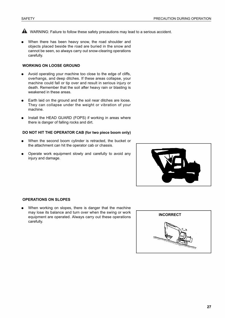
DO NOT HIT THE OPERATOR CAB (for two piece boom only)
� When the second boom cylinder is retracted, the bucket orthe attachment can hit the operator cab or chassis.
� Operate work equipment slowly and carefully to avoid anyinjury and damage.
OPERATIONS ON SLOPES
� When working on slopes, there is danger that the machinemay lose its balance and turn over when the swing or workequipment are operated. Always carry out these operationscarefully.
INCORRECT
27
PRECAUTION DURING OPERATION SAFETY
WARNING: For reasons of safety, always follow these safety precautions.
� Do not swing the work equipment from the uphill side to thedownhill side when the bucket is loaded. This operation isdangerous.(See the upper diagram on the right.)
� If the machine has to be used on a slope, pile the soil to makea platform that will keep the machine as horizontal as possi-ble.(See the lower diagram on the right.)
Piled soil on slope see “PRECAUTIONS WHEN TRAVEL-ING UP OR DOWN HILLS” on page 130.
PARKING THE MACHINE
Park on level ground whenever possible. If not possible, chockthe wheels, lower the bucket to the ground and thrust the bucketin the ground.
� When parking on public roads, provide fences and signs,such as flags or lights, on the machine to warn passersby tobe careful. Be sure that the machine, flags or lights do notobstruct traffic.
Parking procedure, see “PARKING MACHINE” onpage 136.
� When leaving the machine, lower the work equipment com-pletely to the ground, raise the control lever Pad Safety lockto the LOCK position, then stop the engine and use the key tolock all the equipment. Always take the key with you.
Work equipment posture, see “PARKING MACHINE” onpage 136.
Places to lock, see “LOCKING” on page 138.
TRANSPORTATION
LOADING AND UNLOADING
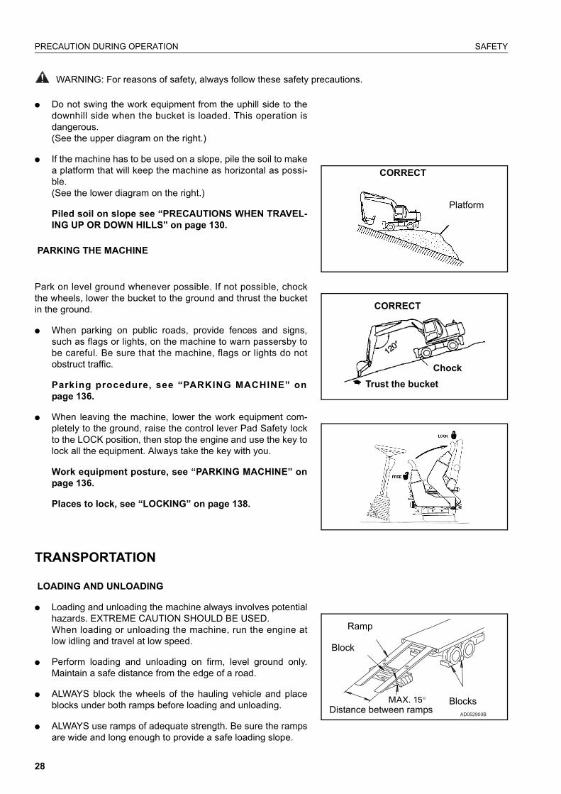
� Loading and unloading the machine always involves potentialhazards. EXTREME CAUTION SHOULD BE USED.When loading or unloading the machine, run the engine atlow idling and travel at low speed.
� Perform loading and unloading on firm, level ground only.Maintain a safe distance from the edge of a road.
� ALWAYS block the wheels of the hauling vehicle and placeblocks under both ramps before loading and unloading.
� ALWAYS use ramps of adequate strength. Be sure the rampsare wide and long enough to provide a safe loading slope.
Platform
CORRECT
CORRECT
ChockTrust the bucket
AD052900B
Block
Ramp
BlocksDistance between ramps
28

SAFETY PRECAUTION DURING OPERATION
WARNING: Failure to follow these safety precautions may lead to a serious accident.
� Be sure that the ramps are securely positioned and fastened,and that the two sides are at the same level as one another.
� Be sure the ramp surface is clean and free of grease, oil, iceand loose materials. Remove dirt from the machine wheels.
� NEVER correct your steering on the ramps. If necessary,drive away from the ramps and climb again.
� Swing the upper structure with extreme care on the trailer toavoid a possible accident caused by body instability.
� After loading, block the machine wheels and secure themachine with tie-downs.
Loading and unloading, see “TRANSPORTATION” onpage 144.
SHIPPING
� When shipping the machine on a hauling vehicle, obey allstate and local laws governing the weight, width, and lengthof a load. Also obey all applicable traffic regulations.
� Determine the shipping route while taking into account thewidth, height and weight of the load.
BATTERY BATTERY HAZARD PREVENTION
� Battery electrolyte contains sulphuric acid and can quicklyburn the skin and eat holes in clothing. If you spill acid onyourself, immediately flush the area with water.
� Battery acid could cause blindness if splashed into the eyes.If acid gets into the eyes, flush them immediately with largequantities of water and see a doctor at once.
� If you accidentally drink acid, drink a large quantity of water ormilk, beaten egg or vegetable oil. Call a doctor or poison pre-vention centre immediately.
� When working with batteries. ALWAYS wear safety glasses orgoggles.
� Batteries generate hydrogen gas. Hydrogen gas is veryEXPLOSIVE, and is easily ignited with a small spark or flame.
� Before working with batteries, stop the engine and turn thestarting switch to the OFF position.
� Avoid short-circuiting the battery terminals through accidentalcontact with metallic objects, such as tools, across the termi-nals.
29

PRECAUTION DURING OPERATION SAFETY
WARNING: For reasons of safety, always follow these safety precautions.
� When removing or installing, check which is the positive (+)terminal and negative (-) terminal.
� Tighten the battery cap securely.
� Tighten the battery terminals securely. Loosened terminalscan generate sparks and lead to an explosion.
� When removing battery cap wear rubber groves to preventelectrolyte contact with skin.
STARTING WITH BOOSTER CABLES
� ALWAYS wear safety glasses or goggles when starting themachine with booster cables.
� When starting from another machine, do not allow the twomachines to touch.
� Be sure to connect the positive (+) cable first when installingthe booster cables. Disconnect the ground or negative (-)cable first when removing them.
� If any tool touches between the positive (+) terminal and thechassis, it will cause sparks. This is dangerous, so be sure towork carefully.
� Connect the batteries in parallel: positive to positive and neg-ative to negative.
� When connecting the ground cable to the frame of themachine to be started, be sure to connect it as far as possiblefrom the battery.
Starting with booster cables, see “IF BATTERY IS DIS-CHARGED” on page 157.
TOWING WHEN TOWING, ATTACH WIRE TO FRAME
� Injury or death could result if a disabled machine is towedincorrectly.
� If you machine is towed by another machine, ALWAYS use awire rope with a sufficient towing capacity.
� NEVER allow a disabled machine to be towed on a slope.
� Do not use a chinked or frayed wire rope.
� Do not straddle the towing cable or wire rope.
� When connecting up a towing machine, do not let anyoneenter the area between the towing machine and the equip-ment being towed.
A0067320A
INCORRECT
Towing holes
Undercarriage
30

SAFETY PRECAUTION DURING OPERATION
WARNING: Failure to follow these safety precautions may lead to a serious accident.
� Set the towing machine and the towing connection of theequipment being towed in a straight line when connecting it.
� Place pieces of wood between the wire ropes and body toprotect them from wear of damage.
� Never tow the machine using the light-duty towing hole.
Towing method, see “METHOD OF TOWING MACHINE”on page 156.
When towing the machine without the engine running or in theadvent of loss of hydraulic pressure, its is necessary to manuallyrelease the park brake, as follows.
View on transmission from front
Releasing the park brake before towing:
1. Unscrew the lock nuts on the park brake release bolts (A)completely (3 places).
2. Screw in the park brake release bolts (A) until the torqueincreases sharply. The park brake is now released.
Resetting the park brake (A) after towing:
1. Unscrew the park brake release bolts (A) completely.
2. Screw in the park brake release bolts by hand until a contactcan be felt at the bolt end. Lock the bolts with the lock nuts.
A
31

PRECAUTION DURING OPERATION SAFETY
WARNING: For reasons of safety, always follow these safety precautions.
BUCKET WITH HOOK OR BUCKET LINK
GENERAL PRECAUTIONS
SPECIAL HOOK
� When carrying out lifting work, the special lifting hook is or lift-ing eye is necessary.
� The following operations are prohibited.
❍ Lifting loads with a wire rope fitted around the bucketteeth.
❍ Lifting loads with the wire rope wrapped directly aroundthe boom or arm.
CHECKING HOOK
� When lifting a load, carry out the following checks to confirmthat there is no abnormality before starting operations.
❍ Check that there are no cracks or deformation in the lift-ing equipment.
❍ Check that there is no abnormality in the stopper device.
HOOKING WIRE ROPE SECURELY TO HOOK
� When performing lifting operation, securely hook the wirerope onto the special lifting hook or lifting eye.
PRECAUTIONS FOR MACHINE INSTALLATION
� After carrying out a preliminary inspection of ground condi-tions, select a flat, solid location. Confirm that the machinecan be safely operated without toppling or rolling.
PROHIBITED OPERATIONS OTHER THAN MAIN APPLICA-TIONS
� When performing lifting operation, never raise or lower a per-son.
NO PERSONS SHALL BE PERMITTED TO ENTER THE WORKING AREA
� Due to the possible danger of the load falling or of collisionwith the load, no persons shall be allowed in the workingarea.
32
SAFETY PRECAUTION DURING OPERATION
WARNING: Failure to follow these safety precautions may lead to a serious accident.
OPERATION SUPERVISOR
� Before performing lifting operation, designate an operationsupervisor.Always execute operation according to his instructions.
❍ Execute operating methods and procedures under hisdirection.
❍ Select a person responsible for signalling. Operate onlyon signals given by such person.
HANDLING OF WIRE ROPES ETC.
� Wear leather gloves when handling wire ropes.
HANDLING OF FLUIDS
� Some oils and other fluids, such as Antifreeze, can be harm-ful to you and the environment, you should therefore alwaysfollow the manufacturers instructions regarding storage, han-dling and disposal.
HANDLING OF USED ENGINE OILS
� Avoid contact with used engine oils.
� Refer to engine oils data sheet for handling and storage pre-cautions.
HANDLING OF OILS
� For diesel oils, hydraulic oils and oils used in the swingmachinery, PTO, transmission axles and hubs avoid pro-longed or frequent contact with skin.
� Refer to manufacturers data sheet for handling and storageprecautions.
HANDLING OF FLUIDS
� For antifreeze and grease refer to manufacturers data sheetfor handling and storage precautions.
PROTECTING EYES
� Some oils and fluids can damage eyes. Refer to manufac-tured data sheet for handling and storage instructions.
PRECAUTIONS FOR LIFTING OPERATION
GRADUAL LIFTING OPERATION
� When carrying out lifting operations, run the engine at lowidling and use the L.O. (lifting operation mode).
� Avoid sudden lever shifting and acceleration.
33

PRECAUTION DURING OPERATION SAFETY
WARNING: For reasons of safety, always follow these safety precautions.
� Swing speed is three to four times that of movable cranes.Therefore, be especially careful when performing swing oper-ation.
NEVER LEAVE THE OPERATOR’S SEAT
� Never leave the operator’s seat while lifting a load.
NEVER CARRY OUT EXCESSIVE OPERATIONS
� Operation exceeding machine performance may result inaccident or failure.
� Carry out lifting operation within specified load limit.
� Never carry out operations which may damage the machinesuch as overload or over-impact-load.
� Never drag a load laterally or longitudinally, nor retract thearm, otherwise, a dangerous situation may result.
NEVER TRAVELLING WHILE LIFTING A LOAD
� Never travel while carrying a load.
OPERATING POSTURE
� If the machine posture is not correct, the wire ropes or ringmay detach from the hook. Confirm that the hook angle is cor-rect to avoid this.
INCORRECT
INCORRECT
34

SAFETY PRECAUTIONS FOR MAINTENANCE
WARNING: Failure to follow these safety precautions may lead to a serious accident.
PRECAUTIONS FOR MAINTENANCE
BEFORE CARRYING OUT MAINTENANCE
WARNING TAG
� If others start the engine or operate the controls while you areperforming service or lubrication, you could suffer seriousinjury or death.
� ALWAYS attach the WARNING TAG to the control lever in theoperator’s cab to alert others that you are working on themachine. Attach additional warning tags around the machine,if necessary.
� These tags are available from your Komatsu distributor. (Partno. 20E-00-K1340)
PROPER TOOLS
� Use only tools suited to the task. Using damaged, low quality,faulty, or makeshift tools could cause personal injury.
Tools, see “INTRODUCTION OF NECESSARY TOOLS” onpage 177.
PERIODIC REPLACEMENT OF SAFETY CRITICAL PARTS
� Replace the following fire-related components periodically:Fuel system: Fuel hose, spilling hose, and fuel tube cap.Hydraulic system: Pump outlet hose.
� Replace these components periodically with new ones,regardless of whether or not they appear to be defective.These components deteriorate over time.
� Replace or repair any such components if any defect is found,event though they have not reached the time specified.
Replacement of safety critical components,see “PERI-ODIC REPLACEMENT OF SAFETY CRITICAL PARTS” onpage 179.
35

PRECAUTIONS FOR MAINTENANCE SAFETY
WARNING: For reasons of safety, always follow these safety precautions.
STOP THE ENGINE BEFORE CARRYING OUT INSPECTION AND MAINTENANCE
� Always stop the machine on firm flat ground and stop theengine before carrying out inspection and maintenance.
� If it is necessary to run the engine when carrying out mainte-nance, such as when cleaning the inside of the radiator,Raise the tilting arm rest to the LOCK position and carry outthe operation with two workers.
� One worker should sit in the operator’s seat so that he canstop the engine immediately if necessary. He should also beextremely careful not to touch any lever by mistake. Touch thelevers only when they have to be operated.
� The worker carrying out the maintenance should beextremely careful not to touch or get caught in the movingparts.
RULES TO FOLLOW WHEN ADDING FUEL OR OIL
� Spilt fuel and oil may cause you to slip, so always wipe it upimmediately.
AM089160A
HEAT OFF
ON
ST
AR
T
36

SAFETY PRECAUTIONS FOR MAINTENANCE
WARNING: Failure to follow these safety precautions may lead to a serious accident.
� Always tighten the cap of the fuel and oil fillers securely.
� Never use fuel for washing any parts.
� Always add fuel and oil in a well-ventilated place.
RADIATOR WATER LEVEL
� If it is necessary to add water to the radiator, stop the engineand allow the engine and radiator to cool down before addingthe water.
� Slowly loosen the caps to relieve pressure before removingthe caps.
37

PRECAUTIONS FOR MAINTENANCE SAFETY
WARNING: For reasons of safety, always follow these safety precautions.
USE OF LIGHTING
� When checking fuel, oil, coolant, or battery electrolyte, alwaysuse lighting with anti-explosion specifications.If such lighting equipment is not used, there is danger ofexplosion.
DURING MAINTENANCE
PERSONNEL
� Only authorised personnel can service and repair themachine. Extra precaution should be used when grinding,welding, and using a sledge-hammer.
ATTACHMENTS
� Place attachments that have been removed from the machinein a safe place so that they do not fall. If they fall on you orothers, serious injury could result.
WORK UNDER THE MACHINE
� Always lower all movable work equipment to the ground or totheir lowest position before performing service or repairsunder the machine.
� Always chock the wheels of the machine securely.
� Never work under the machine if the machine is poorly sup-ported.
KEEP THE MACHINE CLEAN
� Spilt oil or grease, or scattered tools or broken pieces aredangerous because they may cause you to slip or trip.Always keep your machine clean and tidy.
38

SAFETY PRECAUTIONS FOR MAINTENANCE
WARNING: Failure to follow these safety precautions may lead to a serious accident.
� If water gets into the electrical system, there is danger thatthe machine may not move or may move unexpectedly.Do not use water or steam to clean the sensors, connectors,or the inside of the operator’s compartment.
PRECAUTIONS WITH BATTERY
� When repairing the electrical system or when carrying outelectrical welding, remove the negative (-) terminal of the bat-tery to stop the flow of current.
HANDLING HIGH-PRESSURE HOSES
� Do not bend high-pressure hoses or hit them with hardobjects. Do not use any bent or cracked piping, tubes orhoses. They may burst during use.
� Always repair any loose or broken fuel hoses or oil hoses. Iffuel or oil leaks, it may cause a fire.
PRECAUTIONS WITH HIGH PRESSURE OIL
� Do not forget that the work equipment circuits are alwaysunder pressure.
� Do not add oil, drain oil, or carry out maintenance or inspec-tion before completely releasing the internal pressure.
� If oil is leaking under high pressure from small holes, it is dan-gerous if the jet of high-pressure oil hits your skin or entersyour eyes. Always wear safety glasses and thick gloves, anduse a piece of cardboard or a sheet of wood to check for oilleakage.
� If you are hit by a jet of high-pressure oil, consult a doctorimmediately for medical attention.
PRECAUTIONS WHEN CARRYING OUT MAINTENANCE AT HIGH TEMPERATURE OR HIGH PRESSURE
� Immediately after stopping operations, the engine coolingwater and oil at all parts is at high temperature and under highpressure.In this condition, if the cap is removed, or the oil or water are
A0055180A
A055190A
39
SAFETY PRECAUTIONS FOR MAINTENANCE
WARNING: Failure to follow these safety precautions may lead to a serious accident.
drained, or the filters are replaced, this may result in burns orother injury. Wait for the temperature to go down, then carryout the inspection and maintenance in accordance with theprocedures given in this manual.
Cleaning inside or cool ing system, see “WHENREQUIRED” on page 188.
Checking cooling water level, hydraulic oil level, see“CHECK BEFORE STARTING” on page 200.
Checking lubricating oil level, adding oil, see “MAINTE-NANCE SCHEDULE CHART” on page 181.
Changing oil, replacing filters, see “MAINTENANCESCHEDULE CHART” on page 181.
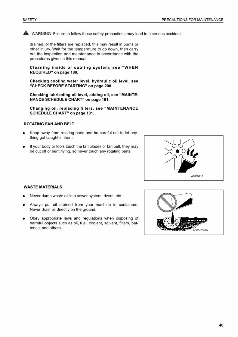
ROTATING FAN AND BELT
� Keep away from rotating parts and be careful not to let any-thing get caught in them.
� If your body or tools touch the fan blades or fan belt, they maybe cut off or sent flying, so never touch any rotating parts.
WASTE MATERIALS
� Never dump waste oil in a sewer system, rivers, etc.
� Always put oil drained from your machine in containers.Never drain oil directly on the ground.
� Obey appropriate laws and regulations when disposing ofharmful objects such as oil, fuel, coolant, solvent, filters, bat-teries, and others.
A0055220A
40

POSITION FOR ATTACHING SAFETY LABELS SAFETY
WARNING: For reasons of safety, always follow these safety precautions.
POSITION FOR ATTACHING SAFETY LABELS
Always keep these labels clean. If they are lost or damage, attachthem again or replace them with a new labelThere are other labels in addition to the safety labels listed as fol-lows, so handle them in the same way.
Safety labels are available from your Komatsu distributor.
POSITION FOR ATTACHING SAFETY LABELS
41

POSITION FOR ATTACHING SAFETY LABELS SAFETY
WARNING: For reasons of safety, always follow these safety precautions.
1. Warnings for keep clear of swing area, emergency steering,power lines, do not ride on machine, falling objects andbucket cab interference. (20E-00-K1890)
� Improper operation and maintenance can cause seriousinjury or death.
� Read the manuals before operation.
� Follow instructions and warnings in the manuals and labelson the machine.
� Keep this manual in the machine cab, near operator.
� If this manual is lost, please contact Komatsu distributor forreplacement.
� Always apply lock when leaving operators seat.
� Normal steering can only be operated when the engine is run-ning.
� Emergency steering only to be used when stopping themachine safely.
� Serious injury or death can occur if machine or attachmentsare not kept a safe distance away from electric lines.
� No passengers allowed to ride on machine while it is moving.
� Do not operate where a danger of falling objects exists. Con-sult your dealer for fitting of FOPS protection.
� Bucket hits operator cab. Read manual before operation.
2. Warning for staying clear (20E-00-K1260)
42

SAFETY POSITION FOR ATTACHING SAFETY LABELS
WARNING: Failure to follow these safety precautions may lead to a serious accident.
3. Amber reflector (20G-46-K1680)
4. Warning for unsafe machine (20E-00-K1340)Do not start
5. Warning for accumulator (20E-00-K1210)
Warnings for handling accumulator.Explosion hazard
� Keep away from flame.
� Do not weld or drill.
� Read operation manual before operation.
6. Warning for staying clear (20E-00-K1150)
Keeping out of moving area. To prevent SEVERE INJURY or DEATH.Do the following before moving the machine or its attachments:
� Sound horn to alert people nearby.
� Be sure no one is on or near machine or in the swing area.
� Rotate cab for full view of travel path if it can be done safely.
� Use spotter if view is obstructed. Follow above even ifmachine equipped with travel alarm and mirrors.
43

POSITION FOR ATTACHING SAFETY LABELS SAFETY
WARNING: For reasons of safety, always follow these safety precautions.
7. Warning for hot objects (20E-00-K1190)
Warning for high temperature coolant and oil, hot water and oilhazard.
To prevent hot water and oil from spurting out:
� Turn engine off.
� Allow water to cool.
� Slowly loosen cap to relieve pressure before removing.
� Read operation manual before operation.
8. Control lever pad safety lock (20E-00-k1850)
9. Warning for staying clear (20E-00-K1140)
Keeping out of moving area.
To prevent SEVERE INJURY or DEATH.
Do the following before moving the machine or its attachments:
� Sound horn to alert people nearby.
� Be sure no one is on or near machine or in the swing area.
� Rotate cab for full view of travel path if it can be done safely.
� Use spotter if view is obstructed. Follow above even ifmachine equipped with travel alarm and mirrors.
44
SAFETY POSITION FOR ATTACHING SAFETY LABELS
WARNING: Failure to follow these safety precautions may lead to a serious accident.
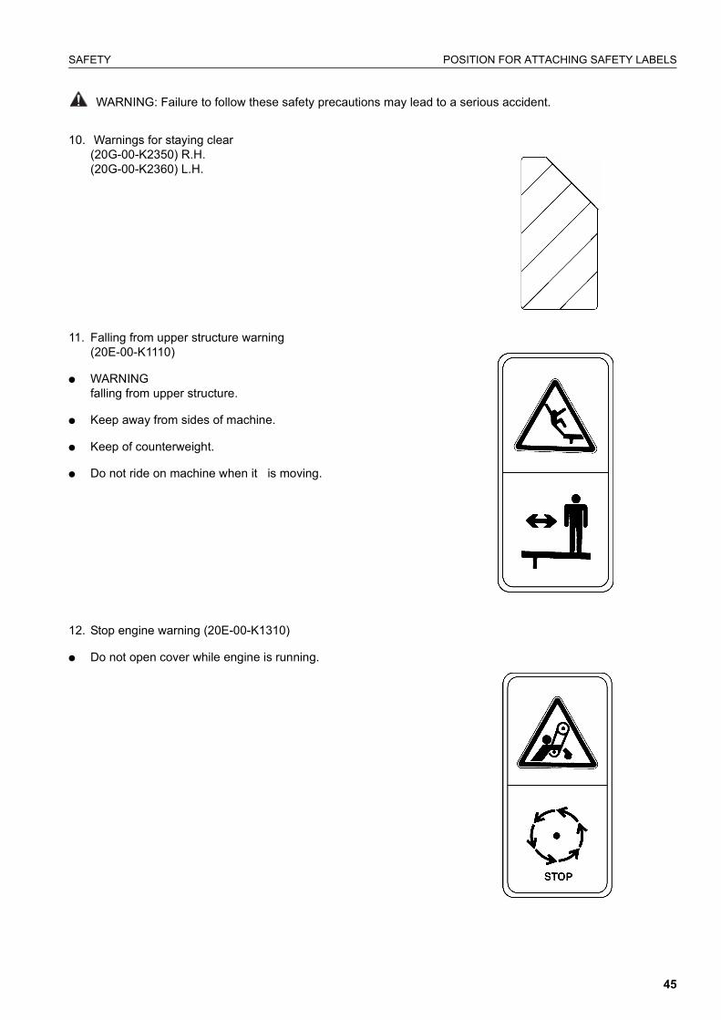
10. Warnings for staying clear (20G-00-K2350) R.H.(20G-00-K2360) L.H.
11. Falling from upper structure warning (20E-00-K1110)
� WARNING falling from upper structure.
� Keep away from sides of machine.
� Keep of counterweight.
� Do not ride on machine when it is moving.
12. Stop engine warning (20E-00-K1310)
� Do not open cover while engine is running.
45

POSITION FOR ATTACHING SAFETY LABELS SAFETY
13. Front windows lock back warning (20E-00-K1230)
� Always apply lock when leaving operator’s seat.
14. High pressure oil warning (20E-00-K1270)
15. 20E-00-K1280
Pump control override switch and swing lock override switch.
Read operation manual before operation.
16. Red reflector (20G-47-K1690)
17. 20Y-00-K2220
� Emergency exit
� Read operation manual before operation
46

SAFETY POSITION FOR ATTACHING SAFETY LABELS
18. Travel Height -UK spec only (20E-00-K1720)
19. Operation of attachments (20G-00-K2273)
ONE PIECE BOOM Arm length 2,10 m
When removing bucket, linkage or cylinder, lifting capacities canbe increased by their respective weights.
A - Reach from swing center
B - Bucket hook height
C - Lifting capacities, including bucket (462 kg), linkage (84 kg) and bucket cylinder (92 kg)
OF: Lifting capacity (rating overfront)OS: Lifting capacity (Rating overside)
- Rating over rear
- Rating over side or 360 degrees
- Rating at maximum reach
unde
r-ca
rria
ge
B AMax 7,5 m 6,0 m 4,5 m 3,0 m 1,5 m
OF OS OF OS OF OS OF OS OF OS OF OS
Bla
de
7.5 m kg * 2800 * 2800
6.0 m kg * 2300 2200 * 3450 * 3300
4.5 m kg * 2150 1650 * 3550 1950 * 3800 3250
3.0 m kg * 2200 1450 3850 1850 * 4700 3050 * 6750 5850
1.5 m kg * 2350 1350 3750 1800 * 5650 2800 * 7400 5250
0.0 m kg * 2700 1400 3650 1700 6000 2650 * 7550 5000
-1.5 m kg * 3400 1650 3650 1700 5900 2650 * 8950 5000 * 5800 * 5800
-3.5 m kg * 3850 2250 * 4800 2700 * 7200 5150
47
POSITION FOR ATTACHING SAFETY LABELS SAFETY
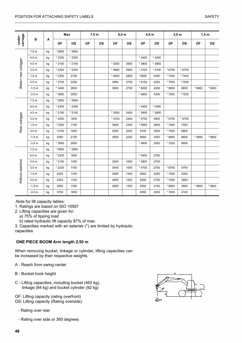
.Note for lift capacity tables:1. Ratings are based on ISO 105672. Lifting capacities are given for: a) 75% of tipping load b) rated hydraulic lift capacity 87% of max.3. Capacities marked with an asterisk (*) are limited by hydrauliccapacities
ONE PIECE BOOM Arm length 2,50 m
When removing bucket, linkage or cylinder, lifting capacities canbe increased by their respective weights.
A - Reach from swing center
B - Bucket hook height
C - Lifting capacities, including bucket (462 kg), linkage (84 kg) and bucket cylinder (92 kg)
OF: Lifting capacity (rating overfront)OS: Lifting capacity (Rating overside)
- Rating over rear
- Rating over side or 360 degrees
Bla
de+
rear
out
rigge
r
7.5 m kg * 2800 * 2800
6.0 m kg * 2300 * 2300 * 3450 * 3450
4.5 m kg * 2150 * 2150 * 3550 2950 * 3800 * 3800
3.0 m kg * 2200 * 2200 * 3850 2900 * 4700 * 4700 * 6750 * 6750
1.5 m kg * 2350 2150 * 4000 2800 *5850 4450 * 7400 * 7400
0.0 m kg * 2700 2250 3950 2700 * 6150 4250 * 7550 * 7550
-1.5 m kg * 3400 2600 3900 2700 * 6000 4200 * 8950 8650 * 5800 * 5800
-3.0 m kg * 3850 3550 * 4800 4300 * 7200 * 7200
Rea
r out
rigge
r
7.5 m kg * 2800 * 2800
6.0 m kg * 2300 * 2300 * 3450 * 3450
4.5 m kg * 2150 * 2150 * 3550 2450 * 3800 * 3800
3.0 m kg * 2200 1850 * 3700 2400 * 4700 3900 * 6750 * 6750
1.5 m kg * 2350 1750 3600 2300 * 5650 3650 * 7400 7050
0.0 m kg * 2700 1850 3550 2550 5700 3500 * 7550 6800
-1.5 m kg 3350 2150 3500 2250 5650 3450 * 8950 6800 * 5800 * 5800
-3.0 m kg * 3850 2900 * 4800 3550 * 7200 6950
With
out s
tabi
lizer
7.5 m kg * 2800 * 2800
6.0 m kg * 2300 1800 * 3450 2750
4.5 m kg * 2150 1350 3050 1600 * 3800 2700
3.0 m kg * 2200 1150 3000 1550 * 4700 2700 * 6750 4750
1.5 m kg 2200 1100 2900 1450 4650 2300 * 7400 4200
0.0 m kg 2300 1100 2800 1400 4500 2150 * 7550 3950
-1.5 m kg 2650 1300 2800 1350 4550 2100 * 8950 3950 * 5800 * 5800
-3.0 m kg 3700 1850 4550 2200 * 7200 4100
unde
r-ca
rria
ge
B AMax 7,5 m 6,0 m 4,5 m 3,0 m 1,5 m
OF OS OF OS OF OS OF OS OF OS OF OS
48

SAFETY POSITION FOR ATTACHING SAFETY LABELS
- Rating at maximum reach
.Note for lift capacity tables:1. Ratings are based on ISO 105672. Lifting capacities are given for: a) 75% of tipping load b) rated hydraulic lift capacity 87% of max.3. Capacities marked with an asterisk (*) are limited by hydrauliccapacities
unde
r-ca
rria
ge
B AMax 7,5 m 6,0 m 4,5 m 3,0 m 1,5 m
OF OS OF OS OF OS OF OS OF OS OF OS
Blad
e
7.5 m kg * 2200 * 2200 * 2500 * 2500
6.0 m kg * 1850 * 1850 * 2000 1950
4.5 m kg * 1750 1500 * 3300 2000 * 3450 * 3300
3.0 m kg * 1800 1300 * 3700 1900 * 4400 3100 * 6050 * 6050
1.5 m kg * 1950 1250 3800 1800 * 5400 2900 * 6650 5400
0.0 m kg * 2200 1300 3700 1750 6000 2700 * 7950 5050
-1.5 m kg * 2750 1450 3650 1700 5950 2650 * 9300 5000 * 5250 * 5250
-3.0 m kg * 3750 1950 * 5250 2650 * 7900 5100 * 8800 * 8800
Blad
e+ re
ar o
utrig
ger
7.5 m kg * 2200 * 2200 * 2500 * 2500
6.0 m kg * 1850 * 1850 * 2000 * 2000
4.5 m kg * 1750 * 1750 * 3300 3000 * 3450 * 3450
3.0 m kg * 1800 * 1800 * 3700 2950 * 4400 * 4400 * 6050 * 6050
1.5 m kg * 1950 * 1950 4050 2800 * 5400 4500 * 8650 * 8650
0.0 m kg * 2200 2050 3950 2750 * 6050 4300 * 7950 * 7950
-1.5 m kg * 2750 2350 3900 2700 * 6100 4250 * 9300 8650 * 5250 * 5250
-3.0 m kg * 3750 3050 * 5250 4250 * 7900 * 7900 * 8800 * 8800
Rea
r out
rigge
r
7.5 m kg * 2200 * 2200 * 2500 * 2500
6.0 m kg * 1850 * 1850 * 2000 * 2000
4.5 m kg * 1750 * 1750 * 3300 2500 * 3450 * 3450
3.0 m kg * 1800 1700 * 3700 2450 * 4400 3950 * 6050 * 6050
1.5 m kg * 1950 1650 3650 2350 * 5400 3700 * 6650 7250
0.0 m kg * 2200 1700 3550 2250 5750 3550 * 7950 6850
-1.5 m kg * 2750 1900 3500 2250 5850 3450 * 9300 6800 * 5250 * 5250
-3.0 m kg * 3750 2500 * 5250 3450 * 7900 6900 * 8800 * 8800
With
out s
tabi
lizer
7.5 m kg * 2200 * 2200 * 2500 * 2500
6.0 m kg * 1850 1600 * 2000 1600
4.5 m kg * 1750 1200 3100 1650 * 3450 2750
3.0 m kg * 1800 1050 3000 1550 * 4400 2600 * 6050 5000
1.5 m kg * 1950 1000 2900 1500 4750 2350 * 6650 4350
0.0 m kg 2100 1000 2800 1400 4550 2200 * 7950 4000
-1.5 m kg 2400 1150 2800 1350 4450 2100 * 9300 3950 * 5250 * 5250
-3.0 m kg * 3150 1150 4450 2150 * 7900 4050 * 8800 * 8800
49

POSITION FOR ATTACHING SAFETY LABELS SAFETY
TWO PIECE BOOM Arm length 2,10 m
When removing bucket, linkage or cylinder, lifting capacities canbe increased by their respective weights.
A - Reach from swing center
B - Bucket hook height
C - Lifting capacities, including bucket (462 kg), linkage (84 kg) and bucket cylinder (92 kg)
OF: Lifting capacity (rating overfront)OS: Lifting capacity (Rating overside)
- Rating over rear
- Rating over side or 360 degrees
- Rating at maximum reach
unde
r-ca
rria
ge
B AMax 7,5 m 6,0 m 4,5 m 3,0 m 1,5 m
OF OS OF OS OF OS OF OS OF OS OF OS
Blad
e
7.5 m kg * 2700 * 2700
6.0 m kg * 2200 1950 * 3100 * 3100
4.5 m kg * 2050 1500 * 3250 1900 * 3550 3200
3.0 m kg * 2050 1300 * 3600 1850 * 4450 3000 * 6700 5800
1.5 m kg 2150 1200 3750 1750 5350 2750
0.0 m kg 2450 1250 3650 1650 5850 2600 5300 4900
-1.5 m kg 2950 1450 3600 1650 5750 2550 8600 4950 4550 4550
-3.0 m kg 3500 1950 * 4850 2600 7150 5050
Blad
e+ re
ar o
utrig
ger
7.5 m kg * 2700 * 2700
6.0 m kg * 2200 1950 * 3100 * 3100
4.5 m kg * 2050 * 2050 * 3250 2950 * 3550 * 3550
3.0 m kg * 2050 * 2050 * 3600 2650 * 4450 * 4450 * 6700 * 6700
1.5 m kg * 2150 2000 * 4000 2750 * 5350 4400
0.0 m kg * 2450 2050 3900 2700 * 5850 4200 * 5300 * 5300
-1.5 m kg * 2950 2350 3900 2650 * 5750 4150 * 8600 8600 * 4550 * 4550
-3.0 m kg 3500 3150 * 4850 4250 * 7150 * 7150
Rea
r out
rigge
r
7.5 m kg * 2700 * 2700
6.0 m kg * 2200 1600 * 3100 2750
4.5 m kg * 2050 1200 3050 1650 * 3550 2700
3.0 m kg * 2050 1000 2950 1600 * 4450 2450 * 6700 4700
1.5 m kg 2050 950 2650 1500 4650 2250
0.0 m kg 2100 1000 2750 1400 4450 2100 * 5300 3850
-1.5 m kg 2400 1150 2750 1400 4400 2050 * 8600 3900 * 4550 * 4550
-3.0 m kg 3250 1600 4500 2100 * 7150 4000
50

SAFETY POSITION FOR ATTACHING SAFETY LABELS
.Note for lift capacity tables:1. Ratings are based on ISO 105672. Lifting capacities are given for: a) 75% of tipping load b) rated hydraulic lift capacity 87% of max.3. Capacities marked with an asterisk (*) are limited by hydrauliccapacities
TWO PIECE BOOM Arm length 2,50 m
When removing bucket, linkage or cylinder, lifting capacities canbe increased by their respective weights.
A - Reach from swing center
B - Bucket hook height
C - Lifting capacities, including bucket (462 kg),
linkage (84 kg) and bucket cylinder (92 kg)
OF: Lifting capacity (rating overfront)OS: Lifting capacity (Rating overside)
- Rating over rear
- Rating over side or 360 degrees
- Rating at maximum reach
With
out s
tabi
lizer
7.5 m kg * 2700 * 2700 * 3450 2750
6.0 m kg * 2200 * 2200 3050 1600 * 3800 2700
4.5 m kg * 2050 * 2050 3000 1550 * 4700 2500 * 6750 4750
3.0 m kg * 2050 * 2050 2900 1450 4650 2300 * 7400 4200
1.5 m kg * 2150 2000 2800 1400 4500 2150 * 7550 3950
0.0 m kg 2450 2050 2800 1400 4500 2150 * 7550 3950
-1.5 m kg 2950 2350 2800 1350 4550 2100 * 8650 3950 * 5800 * 5800
-3.0 m kg 3500 3150 4550 2200 * 7200 4100
unde
r-ca
rria
ge
B AMax 7,5 m 6,0 m 4,5 m 3,0 m 1,5 m
OF OS OF OS OF OS OF OS OF OS OF OS
unde
rca
rria
ge
B AMax 7,5 m 6,0 m 4,5 m 3,0 m 1,5 m
OF OS OF OS OF OS OF OS OF OS OF OS
Blad
e
7.5 m kg * 2100 * 2100 * 3000 * 3000
6.0 m kg * 1800 1700 * 2900 1950
4.5 m kg * 1650 1350 * 3000 1950 * 3200 * 3200
3.0 m kg * 1650 1200 * 2100 1200 * 3400 1900 * 4150 3100 * 5900 * 5900
1.5 m kg * 1750 1100 2550 1150 3750 1750 * 5150 2800 * 6300 5300
0.0 m kg * 2000 1150 3650 1700 * 5800 2650 * 5750 4950
-1.5 m kg * 2400 1300 3600 1850 * 5850 2550 * 8450 4900
-3;0 m kg * 3300 1700 * 5200 2600 * 7750 5000
51

POSITION FOR ATTACHING SAFETY LABELS SAFETY
.Note for lift capacity tables:1. Ratings are based on ISO 105672. Lifting capacities are given for: a) 75% of tipping load b) rated hydraulic lift capacity 87% of max.3. Capacities marked with an asterisk (*) are limited by hydrauliccapacities
Blad
e+ re
ar o
utrig
ger
7.5 m kg * 2100 * 2100
6.0 m kg * 1800 * 1800 * 2900 * 2900
4.5 m kg * 1650 * 1650 * 3000 3000 * 3200 * 3200
3.0 m kg * 1650 * 1650 * 2100 1950 * 3400 2900 * 4150 * 4150 * 5900 * 5900
1.5 m kg * 1750 * 1750 2750 1900 * 3850 2800 * 5150 4450 * 6300 * 6300
0.0 m kg * 2000 1900 3900 2700 * 5800 4250 * 5700 * 5700
-1.5 m kg * 2400 2150 3900 2650 * 5850 4200 * 8450 * 8450 * 4200 * 4200
-3;0 m kg * 3300 2700 * 5200 2600 * 7750 5000
Rea
r out
rigge
r
7.5 m kg * 2100 * 2100
6.0 m kg * 1800 * 1800 * 2900 2500
4.5 m kg * 1650 * 1650 * 3000 2500 * 3200 * 3200
3.0 m kg * 1650 1550 * 2100 1600 * 3400 2900 * 4150 3950 * 5900 * 5900
1.5 m kg * 1750 1500 2550 1550 * 3850 2300 * 5150 3650 * 6300 * 6300
0.0 m kg * 2000 1550 3500 2200 5700 3450 * 5700 * 5700
-1.5 m kg * 2400 1750 3500 2150 5600 3400 * 8450 6750 * 4200 * 4200
-3;0 m kg * 3300 2250 * 5200 3450 * 7750 8650
With
out s
tabi
lizer
7.5 m kg * 2100 * 2100 * 3000 2750
6.0 m kg * 1800 1400 * 2900 1600
4.5 m kg * 1650 1100 * 3000 1600 * 3200 2750
3.0 m kg * 1650 950 2000 950 3000 1550 * 4150 2550 * 5900 4950
1.5 m kg * 1750 850 1950 900 2900 1450 4700 2300 6300 4200
0.0 m kg 1950 900 2800 1350 4500 2100 5700 3900
-1.5 m kg 2200 1050 2750 1300 4400 2050 * 8450 3850 * 4200 * 4200
-3;0 m kg 2800 1350 4450 2100 * 7750 3950
unde
rca
rria
ge
B AMax 7,5 m 6,0 m 4,5 m 3,0 m 1,5 m
OF OS OF OS OF OS OF OS OF OS OF OS
52

SAFETY POSITION FOR ATTACHING SAFETY LABELS
ROTATING ARMU
nder
carr
iage
Arm
leng
th
Hei
ght
max 7.5 m 6.0 m 4.5 m 3.0 m 1.5
OF OS OF OS OF OS OF OS OF OS OF OS
Fron
t out
rigge
r + re
ar b
lade
2600
7.5 m *1950 * 1950
6.0 m * 1600 * 1600 * 2600 * 2600
4.5 m * 1500 * 1500 * 2650 * 2650 * 2850 * 2850
3.0 m * 1500 * 1500 * 2300 1700 * 3000 2650 * 3700 * 3700 * 5300 * 5300
1.5 m * 1600 1550 2550 1650 * 3450 2500 * 4600 4050 * 6850 * 6850
0.0 m * 1750 1600 * 2200 1600 3600 2350 * 5250 3800 * 5700 * 5700
-1.5 m * 2100 1800 3550 2300 * 5300 3700 * 8250 7750 * 4000 * 4000
-3 m * 2900 2350 * 3100 2400 * 4750 3750 * 7150 * 7150 * 7200 * 7200
Fron
t + re
ar o
utrig
ger
7.5 m *1950 * 1950
6.0 m * 1600 * 1600 * 2600 * 2600
4.5 m * 1500 * 1500 * 2650 * 2650 * 2850 * 2850
3.0 m * 1500 * 1500 * 2300 * 2300 * 3000 * 3000 * 3700 * 3700 * 5300 * 5300
1.5 m * 1600 * 1600 2400 2300 * 3450 3400 * 4600 * 4600 * 6850 * 6850
0.0 m * 1750 * 1750 * 2200 * 2200 3450 2350 * 5250 3800 * 5700 * 5700
-1.5 m * 2100 1800 3550 2300 * 5300 5200 * 8250 * 8250 * 4000 * 4000
-3 m * 2900 * 2900 * 3100 * 3100 * 4750 * 4750 * 7150 * 7150 * 7200 * 7200
53

POSITION FOR ATTACHING SAFETY LABELS SAFETY
OVERLOAD CAUTION
This machine is equipped with an overload caution system whichgives a visual warning (on monitor) and an audible warning whenlifting a load close to the to the lift capacity of the machine (activein L.o. mode only).
A decal inside the operators cab shows the loads at which thecaution warning is given for various work equipment positions.
Due to the simple nature of the system the overload warning isgiven at a lower load than actually allowable (see full lift capacitycharts)
If lifting to the full capacity of the machine is required it is neces-sary to fit a full overload caution system (with work equipmentposition sensing to the machine.
Decal showing lifting loads (in kg) at overload warning.
54

OPERATION
55

GENERAL VIEW OPERATION
GENERAL VIEW
GENERAL VIEW OF MACHINEIf directions are indicated in this section, they refer to the direc-tions shown by in the arrows in the diagram below.
A: FRONT B: REAR C: RIGHT D: LEFT
1. Bucket 5. Boom
2. Bucket cylinder 6. Boom Cylinder
3. Arm 7. Undercarriage
4. Arm cylinder
56

OPERATION GENERAL VIEW
GENERAL VIEW OF CONTROLS AND GAUGES
1. Control lever pad safety lock 15. Swing lock switch
2. Horn 16. Control lever lock switch
3. Left work equipment control 17. Lamp switch
4. Power max. Button 18. Alarm buzzer stop switch
5. Horn, wiper, washer, dip/main headlights indicators 19. Lower switch
6. L.H. Clamshell rotation switch 20. Beacon switch
7. Boom switch 21. Heated seat switch
8. Machine monitor 22. Heater/Air conditioner control
9. R.H. Clamshell rotation, switch/breaker switch 23. 12 V power supply
10. Undercarriage attachment switch 24. Outriggers L/R, Hazard, park brake, roadlight, Axle lock switches.
11. Right work equipment control lever 25. Travel pedal
12. Starting switch 26. Brake pedal
13. Fuel control dial 27. Steering column, Release pedal
14. Cigarette lighter 28. piece boom pedal
57
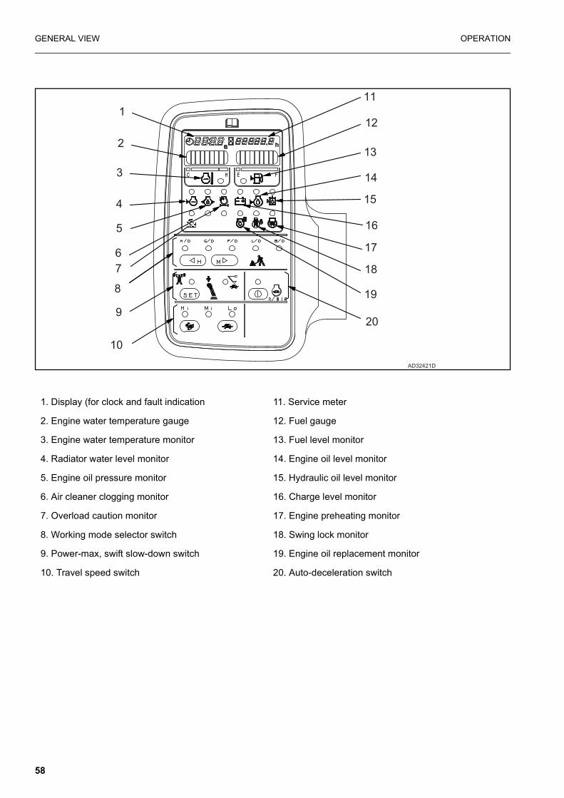
GENERAL VIEW OPERATION
1. Display (for clock and fault indication 11. Service meter
2. Engine water temperature gauge 12. Fuel gauge
3. Engine water temperature monitor 13. Fuel level monitor
4. Radiator water level monitor 14. Engine oil level monitor
5. Engine oil pressure monitor 15. Hydraulic oil level monitor
6. Air cleaner clogging monitor 16. Charge level monitor
7. Overload caution monitor 17. Engine preheating monitor
8. Working mode selector switch 18. Swing lock monitor
9. Power-max, swift slow-down switch 19. Engine oil replacement monitor
10. Travel speed switch 20. Auto-deceleration switch
AD32421D
1
2
3
4
5
67
8
9
10
11
12
13
14
15
16
17
18
19
20
58
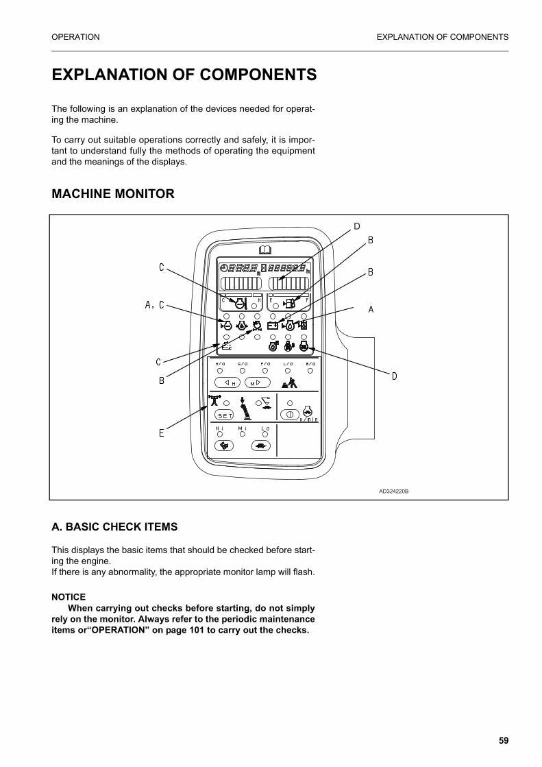
OPERATION EXPLANATION OF COMPONENTS
EXPLANATION OF COMPONENTS
The following is an explanation of the devices needed for operat-ing the machine.
To carry out suitable operations correctly and safely, it is impor-tant to understand fully the methods of operating the equipmentand the meanings of the displays.
MACHINE MONITOR
A. BASIC CHECK ITEMS
This displays the basic items that should be checked before start-ing the engine.If there is any abnormality, the appropriate monitor lamp will flash.
NOTICEWhen carrying out checks before starting, do not simply
rely on the monitor. Always refer to the periodic maintenanceitems or“OPERATION” on page 101 to carry out the checks.
D
AD324220B
59

EXPLANATION OF COMPONENTS OPERATION
B. CAUTION ITEMS
CAUTION
If these monitor items flash, check and repair the appropriate location as soon as possible.
These are items which need to be observed while the engine isrunning.If any abnormality occurs, items which need to be repaired assoon as possible are displayed.
If there is any abnormality, the appropriate monitor lamp will flashto indicate the location of the abnormality.
C. EMERGENCY STOP ITEMS
CAUTION
If these monitors items flash, stop operations immediately, then check and repair the appropriate location.
These are items which need to be observed while the engine isrunning. If any abnormality occurs, items which need to berepaired immediately are displayed.If there is any abnormality, the appropriate monitor lamp will flashto indicate the location of the abnormality and the buzzer willsound.
D. METER DISPLAY PORTION
This portion consists of pre-heating monitor, swing lock monitor,engine water temperature gauge, fuel gauge and display.
E. SWITCHES
The switches are used for setting clock time and for selectingworking mode and travel speed.
60

OPERATION EXPLANATION OF COMPONENTS
A: BASIC CHECK ITEMS
NOTICEDo not rely on the “BASIC CHECK ITEMS” only for the
check before startingAlways refer to the periodic maintenance items or "OPERA-TION" to carry out the checks.
1. RADIATOR WATER LEVEL
This warns that the radiator cooling water level is too low. If themonitor lamp flashes, check the cooling water level in the radiatorand reserve tank, and add water.
2. ENGINE OIL LEVEL
This warns that the oil level in the engine oil pan is too low. If themonitor lamp flashes, check the oil level in the engine oil pan, andadd oil.
4
AD324230
61

EXPLANATION OF COMPONENTS OPERATION
B: CAUTION ITEMS
CAUTION
If the caution monitor lamp flashes, repair the problem as soon as possible.
1. CHARGE LEVEL
This monitor indicates an abnormality in the charging systemwhile the engine is running. If the monitor lamp flashes, check theV-belt tension.
If any abnormality is found, see “OTHER TROUBLE” onpage 159.
REMARKWhile the starting switch is ON, the lamp will remain lit and
will go off once the engine is started.
2. FUEL LEVEL
If the fuel drops below 55 liters, the lamp will flash. Top up the fuelbefore this.
3. AIR CLEANER CLOGGING
This warns that the air cleaner is clogged.If the monitor lamp flashes, stop the engine then inspect andclean the air cleaner.
4. OVERLOAD CAUTION (When in LO mode)
This warns that the machine is close to tipping due to the load (anaudible warning is also given), if the warning is given lower theload. Refer to the lifting capacity chart for safe load.(see section10)
62

OPERATION EXPLANATION OF COMPONENTS
C: EMERGENCY STOP ITEMS
If any monitor lamp flashes, stop the engine or run it at low idling,and take the following action.
1. ENGINE WATER TEMPERATURE
If the temperature of the engine cooling water becomes abnor-mally high, the monitor lamp flashes, and the overheat preventionsystem is automatically actuated to reduce the engine speed.
Stop operations and run the engine at low idling until the enginewater temperature gauge enters the green range.
2. RADIATOR WATER LEVEL
If the radiator water level drops, the monitor lamp flashes. Stopthe engine, check the radiator water level, and add water if neces-sary.
3. ENGINE OIL PRESSURE
If the engine oil pressure drops below the normal pressure, themonitor lamp flashes. At this item, stop the engine and inspect itaccording to “OTHER TROUBLE” on page 159
REMARKWhile the starting switch is ON, the lamp remains lit and goes
off once the engine is started. When the engine starts, the buzzermay sound for a short time, however, this does not indicate afault.
63
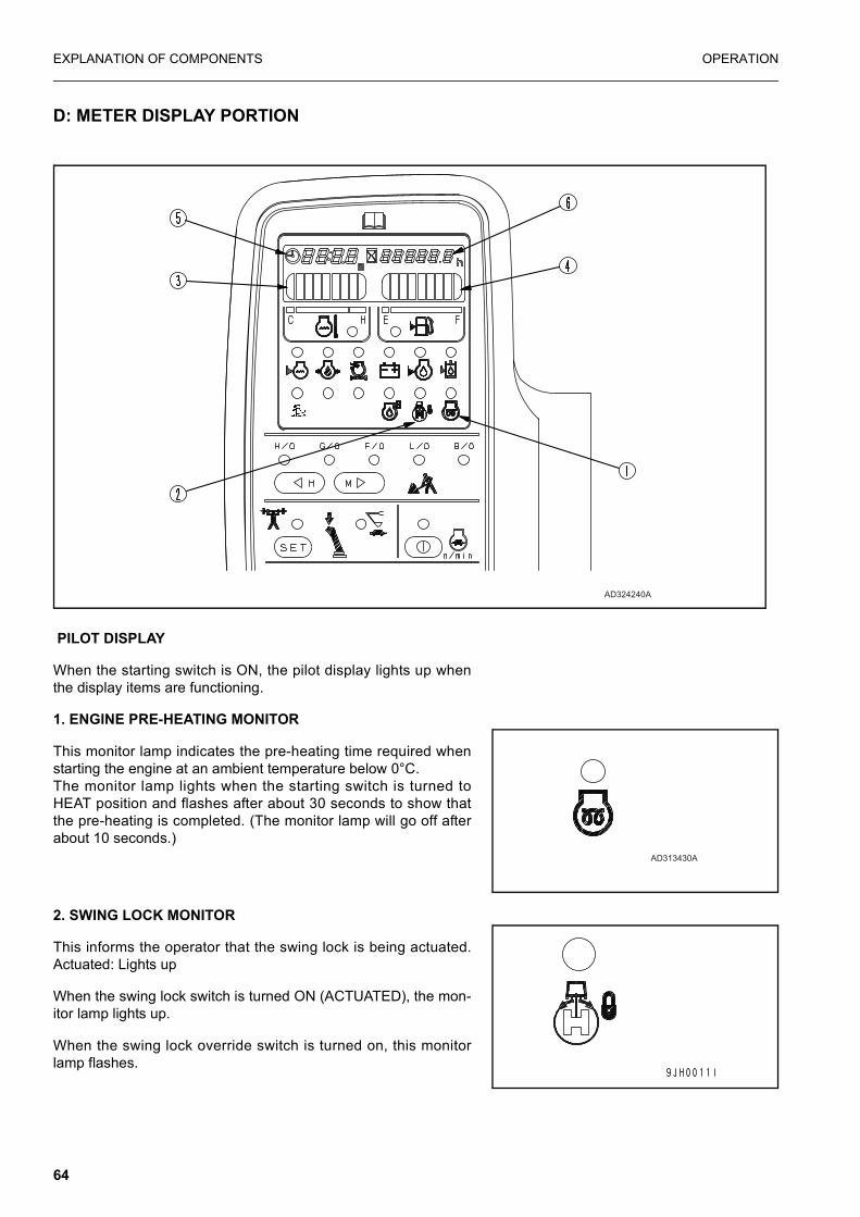
EXPLANATION OF COMPONENTS OPERATION
D: METER DISPLAY PORTION
PILOT DISPLAY
When the starting switch is ON, the pilot display lights up whenthe display items are functioning.
1. ENGINE PRE-HEATING MONITOR
This monitor lamp indicates the pre-heating time required whenstarting the engine at an ambient temperature below 0°C.The monitor lamp lights when the starting switch is turned toHEAT position and flashes after about 30 seconds to show thatthe pre-heating is completed. (The monitor lamp will go off afterabout 10 seconds.)
2. SWING LOCK MONITOR
This informs the operator that the swing lock is being actuated.Actuated: Lights up
When the swing lock switch is turned ON (ACTUATED), the mon-itor lamp lights up.
When the swing lock override switch is turned on, this monitorlamp flashes.
AD324240A
AD313430A
64

OPERATION EXPLANATION OF COMPONENTS
REMARKA disc brake is installed in the swing motor to mechanically
stop motor rotation.The brake is always applied while the swing lock is actuated.
METERS
3. ENGINE WATER TEMPERATURE GAUGE
This gauge indicates the engine cooling water temperature. If the temperature is normal during operation, the green range (A)will light up.
If the red range lights (C) up during operation, the overheat pre-vention system will be actuated.
The overheat prevention system acts as follows.
Red range (1) lights up:Output horsepower drops, and water temperature monitor (3)flashes.
When red range (2) lights up:Engine speed is lowered further to low idling, engine water tem-perature monitor (3) lights up, and alarm buzzer sounds at thesame time.
The overheat prevention system is actuated until the temperatureenters the green range.
When red range (2) lights, if the engine water temperature isreduced and the fuel control dial is turned to the low idling posi-tion, the display will be cancelled.
4. FUEL GAUGE
This gauge indicates the amount of fuel in the fuel tank. If the fuellevel is normal during operation, the green range (2) will light up.
If only the red range (1) lights up during operation, there is lessthan 55 liters of fuel remaining in the tank, so check and add fuel.
After the starting switch is turned ON, the correct level may not bedisplayed for a moment, but this does not indicate any abnormal-ity.
When stopping the engine, turn the starting switch ON and checkthat the monitor lamps on items A, B, C and D and the meterslight up.
(A)
(B)C
AW34991D3
1 2
AW34992C
65

EXPLANATION OF COMPONENTS OPERATION
5. DISPLAY
This normally displays the clock time. If there is any abnormality,the type of failure is indicated when the starting switch is turnedON.
Manual setting
1. When the time is displayed, depress clock switch (1) for 2.5sec. or more.
2. 2. “TIME” flashes.
3. Pressing H switch (2) increases hours and pressing M switch(3) in-creases minutes. If switch (2) or (3) is pressed for 2.5seconds or more, hours or minutes increase continuously.
4. When the correct time is reached, press clock switch (1). Thiscompletes clock setting.
Correct time setting
1. When the time is displayed, depress the clock switch for 2.5sec. or more.
2. “TIME” flashes.
3. 3. When SET switch is pressed, the hour is rounded off for 0to 14 minutes and rounded up for 45 to 59 minutes.[Examples) 10:14 becomes 10:00 /rounded off)10:45 becomes 11:00 (rounded up)
When SET switch (4) is pressed at the time signal or standardclock, the correct time is obtained.
4. When the correct time is reached, press clock switch (1).This, completes clock setting.
If the machine has a fault, error information appears while thestarting switch is turned ON. The monitor flashes and displays allerror informations sequentially.
If any of these monitors flashes, see “ELECTRONIC CON-TROL SYSTEM” on page 162.
AD31347C
AD324250A
Monitor indications Error mode
E02 PC-EPC valve system error
E03 Swing brake system error
E05 Governor system error
CALL Non-operating error
66
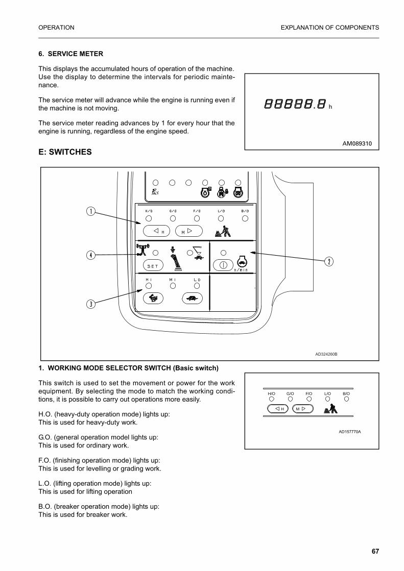
OPERATION EXPLANATION OF COMPONENTS
6. SERVICE METER
This displays the accumulated hours of operation of the machine.Use the display to determine the intervals for periodic mainte-nance.
The service meter will advance while the engine is running even ifthe machine is not moving.
The service meter reading advances by 1 for every hour that theengine is running, regardless of the engine speed.
E: SWITCHES
1. WORKING MODE SELECTOR SWITCH (Basic switch)
This switch is used to set the movement or power for the workequipment. By selecting the mode to match the working condi-tions, it is possible to carry out operations more easily.
H.O. (heavy-duty operation mode) lights up:This is used for heavy-duty work.
G.O. (general operation model lights up:This is used for ordinary work.
F.O. (finishing operation mode) lights up:This is used for levelling or grading work.
L.O. (lifting operation mode) lights up:This is used for lifting operation
B.O. (breaker operation mode) lights up:This is used for breaker work.
AD324260B
AD157770A
H/O G/O F/O L/O B/O
H M
67

EXPLANATION OF COMPONENTS OPERATION
When starting the engine, G.O. (general operation) mode is auto-matically selected. Each time the switch is pressed, the modeselection changes.
NOTICEWhen the breaker is used, never select the H.O. (heavy-
duty operation) mode.
REMARKH switch is also used for setting “hours” in the clock and M
switch for setting “minutes”. see “DISPLAY” on page 66.
2. AUTO-DECELERATION SWITCH (Selection switch)
This switch acts to activate the function that automatically lowersthe engine speed and reduces fuel consumption when the controllever is at neutral.
ON lights up: Auto-deceleration is actuated.OFF: Auto-deceleration is cancelled.
Each time the switch is pressed, the auto-deceleration is actuatedor cancelled.
3. TRAVEL SPEED SWITCH
If the Hi-Lo switch is operated when the machine is travelling, themachine may deviate even when travelling in a straight line. Toprevent this, always stop the machine before operating the travelspeed switch.
This is used to select the three travel speeds.
Lo lights up: Low speed travelMi lights up: Mid range speed travelHi lights up: High speed travel
When the engine is started, the travel speed is automatically setto Lo.
When travelling in Hi, the travel speed is automatically adjusted tomatch the travel surface on soft ground or when travelling uphill,so there is no need to operate this switch. The monitor indicationkeeps lamp Hi lighted.
NOTE: Switching from Hi to Mi or Lo can only be done when themachine is stationary and the service brake is applied(locked).If the Mi or Lo button is pressed without the service brakeapplied the indicator lamp will show selection of thedesired mode but the machine will remain in Hi modeuntil such time as the service brake has been fullyapplied (locked). Switching from Mi to Lo or Hi or from Loto Mi or Hi can be done at any time and whilst travelling.see “MOVING MACHINE FORWARD” on page 119.
AD157780A
AD157790A
68

OPERATION EXPLANATION OF COMPONENTS
4. POWER MAX./SWIFT SLOW-DOWN SWITCH
During operations, the digging power can be increased and thespeed reduced by a one-touch operation of the knob button /sin-gle click while pushing).
Power max. (power up) lights up:When the working mode is heavy-duty and general operationmode only, the power can be increased while the knob button isbeing pressed. Even if the knob button continues to be pressed,the increase in power finishes after approx. 8.5 sec.
Swift slow-down (speed down) lights up:When the working mode is heavy-duty operation and generaloperation mode only, the speed is reduced while the knob buttonis being pressed.
When the engine is started, the power max. lamp lights up. Eachtime this switch on the monitor panel is pressed, the mode isswitched.
AD157800A
69
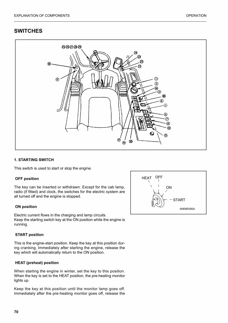
EXPLANATION OF COMPONENTS OPERATION
SWITCHES
1. STARTING SWITCH
This switch is used to start or stop the engine.
OFF position
The key can be inserted or withdrawn. Except for the cab lamp,radio (if fitted) and clock, the switches for the electric system areall turned off and the engine is stopped.
ON position
Electric current flows in the charging and lamp circuits.Keep the starting switch key at the ON position while the engine isrunning.
START position
This is the engine-start position. Keep the key at this position dur-ing cranking. Immediately after starting the engine, release thekey which will automatically return to the ON position.
HEAT (preheat) position
When starting the engine in winter, set the key to this position.When the key is set to the HEAT position, the pre-heating monitorlights up.
Keep the key at this position until the monitor lamp goes off.Immediately after the pre-heating monitor goes off, release the
AM089390A
HEAT OFF
ON
START
70

OPERATION EXPLANATION OF COMPONENTS
key. The key automatically returns to the OFF position. Then,start the engine by turning the key to the START position.
2. FUEL CONTROL DIAL (WITH AUTO-DECELERATION MECHANISM)
This adjusts the engine speed and output.
(1) Low idling (MIN): Turned fully to the left(2) Full speed (MAX): Turned fully to the right
3. CIGARETTE LIGHTER
This is used to light cigarettes. To use, push the lighter in. After afew seconds it will spring back.
Pull out the lighter and light your cigarette. Nothing may be connected to the cigarette lighter without the priorpermission of an authorized Komatsu distributor.
4. SWING LOCK SWITCH
WARNING
� When the machine is travelling under its own power, orwhen the swing is not being operated, always set theswitch to the ON (ACTUATED) position.
� On a slope, the work equipment may swing to the downside even if the swing lock switch is located at the ONposition. Be careful concerning this point.
This switch is used to lock the upper structure so that it cannotswing. ON position (actuated):
The swing lock is always applied, and the upper structure will notswing even if the swing is operated. In this condition, the swinglock lamp lights up.
OFF position (cancelled):
The swing lock is applied only when the swing control lever is atneutral; when the swing control lever is operated, it is cancelled.
The swing lock is actuated approx. 4 seconds after the swinglever is placed in neutral.
71

EXPLANATION OF COMPONENTS OPERATION
5. CONTROL LEVER LOCK SWITCH
WARNING
When travelling on public roads, set this switch to the offposition. This prevents operation of the work equipment andactivates the rear facing brake lamp circuits.
This switch enables operation of the work equipment controllevers.
ON position (actuated):Operation of the control levers must be disabled by use of thisswitch when the machine is travelling on Public roads.
OFF position (deactivated):
The switch is lit in the on (actuated) position.
6. LAMP SWITCH
This switch turns on the working lamps and monitor illumination.
7. ALARM BUZZER STOP SWITCH
This is used to stop the alarm buzzer when it has sounded towarn of some abnormality in the EMERGENCY STOP ITEMSwhile the engine is running.
8. LOWER WIPER SWITCH (If fitted)
This switch actuates the front lower wiper.
OFF: wiper stops
ON: wiper moves continuously
NB. Do not operate with front lower screen removed.
1 2 3(1) OFF
(2) Standard work lamps
(3) Standard and additional work lamps (if fitted)
AM089440A
OFFON
72

OPERATION EXPLANATION OF COMPONENTS
9. HORN BUTTON
When the lower button on the left work equipment control lever ispressed, the horn will sound. Note: Additional horn switch is switch 25.
10. KNOB BUTTON
The upper button of the left work equipment control lever is usedto actuate the power max./swift slow-down functions. Press thebutton once (single click) and keep it depressed. In the heavy-duty and general operation modes, the power max. function actu-ates for max. 8.5 seconds and the swift slow-down function actu-ates while the button is depressed.
11. HEATED OPERATOR SEAT SWITCH (If fitted)
This switch is used to switch on the heated seat.
OFF: seat not heatedON: seat heated
12. BEACON SWITCH (If fitted)
This switch is used to switch on the rotating beacon.
OFFON: beacon lights lights and rotates.
OFF
OFF
73

EXPLANATION OF COMPONENTS OPERATION
13. CAB LAMP SWITCH
This lights up the cab lamp.
ON position: Lights upThe cab lamp can be turned on even when the starting switch isat the OFF position, so be careful not to leave it on by mistake.
14. PUMP CONTROL OVERRIDE SWITCH
(2) When normal: Switch is down
(1) When abnormal: When the monitor display shows E02 (TVCvalve system error), it is possible to carry out operation when thisswitch is moved up. The pump control override switch is designedto allow operations to be carried out for a short period when thereis an abnormality in the pump control system (TVC valve systemerror). The abnormality must be repaired immediately.
15. SWING LOCK OVERRIDE SWITCH
(2) When normal: Switch is down
(1) When abnormal: When the monitor display shows E03 (swingbrake system error), the brake is cancelled and it becomes possi-ble to swing the upper structure when this switch is moved up, sonormal operations can be carried out. However, the swing brakeremains cancelled.
The swing lock override switch is designed to allow operations tobe carried out for a short period when there is an abnormality in
AM089510A
1
2
AM166910B
13
AM166920B14 15
1
2AM089520A
1
2AM089520A
74
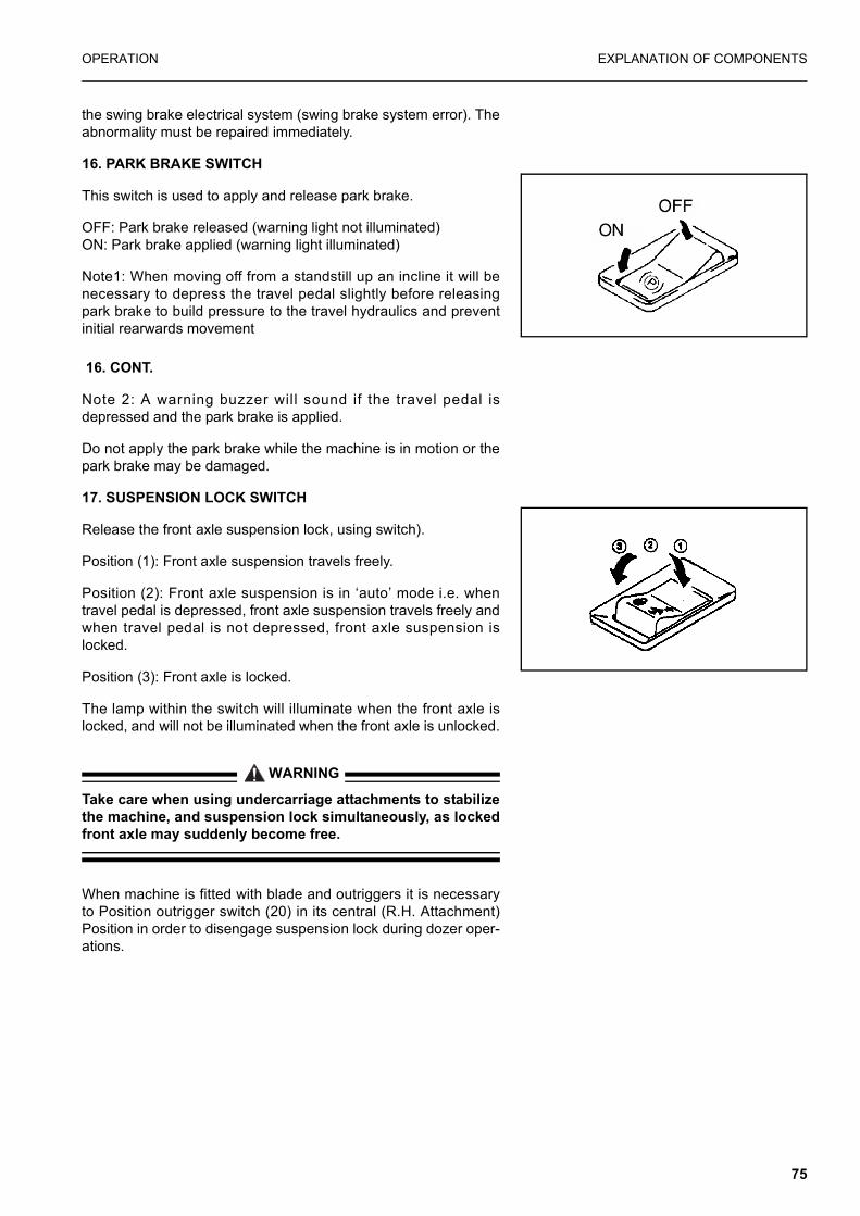
OPERATION EXPLANATION OF COMPONENTS
the swing brake electrical system (swing brake system error). Theabnormality must be repaired immediately.
16. PARK BRAKE SWITCH
This switch is used to apply and release park brake.
OFF: Park brake released (warning light not illuminated)ON: Park brake applied (warning light illuminated)
Note1: When moving off from a standstill up an incline it will benecessary to depress the travel pedal slightly before releasingpark brake to build pressure to the travel hydraulics and preventinitial rearwards movement
16. CONT.
Note 2: A warning buzzer will sound if the travel pedal isdepressed and the park brake is applied.
Do not apply the park brake while the machine is in motion or thepark brake may be damaged.
17. SUSPENSION LOCK SWITCH
Release the front axle suspension lock, using switch).
Position (1): Front axle suspension travels freely.
Position (2): Front axle suspension is in ‘auto’ mode i.e. whentravel pedal is depressed, front axle suspension travels freely andwhen travel pedal is not depressed, front axle suspension islocked.
Position (3): Front axle is locked.
The lamp within the switch will illuminate when the front axle islocked, and will not be illuminated when the front axle is unlocked.
WARNING
Take care when using undercarriage attachments to stabilizethe machine, and suspension lock simultaneously, as lockedfront axle may suddenly become free.
When machine is fitted with blade and outriggers it is necessaryto Position outrigger switch (20) in its central (R.H. Attachment)Position in order to disengage suspension lock during dozer oper-ations.
75

EXPLANATION OF COMPONENTS OPERATION
18. ROADLIGHTS SWITCH
This switch is used to switch on the side lights and road lights.
19. HAZARD SWITCH
This switch is used to switch on the hazard warning lights.
OFF: Hazard warning lights off.
ON: Hazard warning lights on.
(Warning light within switch will flash when switched on).
20. OUTRIGGER LEFT/RIGHT SWITCH (IF FITTED)
This switch enables operation of left, right or simultaneous outrig-ger(s)
21. UNDERCARRIAGE ATTACHMENT SWITCH
This switch enables operation of outriggers and/or dozer blade.
� Machines equipped with dozer blade only:When this button is pressed (a) warning light a in position ofswitch (20) is activated.
� Machines equipped with outriggers or dozer/outrigger:When this button is pressed switch (20) will illumate.
22. BOOM SWITCH
This switch enables operation of the boom when this button ispressed. The warning light in the panel assembly next to switch20 is not illuminated.
(1) OFF
(2) Sidelights (parking lights) on
(3) Road lights on.
(1) Simultaneous LH + RH
(2) Right hand attachment
(3) Left hand attachment
76

OPERATION EXPLANATION OF COMPONENTS
OPERATION OF DOZER + OUTRIGGERS(ensure safety lock lever is unlocked and front axle is locked)
A. To operate front attachment(s)
1. Ensure park brake switch (16) is on.
2. Set outrigger left/right switch (20) to appropriate position.
3. Press undercarriage attachment switch (21).
4. Move right hand wrist lever forward to lower the attachmentand rear-wards to raise the attachment.
22a. UNDERCARRIAGE ATTACHMENT OPERATION WARN-ING LAMP (For machines fitted with dozer blade only)
This lamp will illuminate when undercarriage attachment switchhas been pressed and indicates that when right hand wrist leveris moved forward or rearwards the undercarriage attachment willmove.
When this lamp is not illuminated the right hand wrist lever willoperate the boom raise/lower as normal.
NOTE: If the machine is fitted with outriggers operation of theundercarriage attachment switch will illuminate the outrig-ger left/right switch (20).
B. TO OPERATE REAR ATTACHMENT(S)
1. Ensure park brake switch (16) is off.
2. Set outrigger left/right switch (20) to appropriate position.
3. Press undercarriage attachment switch (21).
4. Move right hand wrist lever forward to lower the attachmentand rearwards to raise the attachment.
77

EXPLANATION OF COMPONENTS OPERATION
WARNING
When moving the machine, confirm that the chassis attach-ment is raised.
PRECAUTIONS FOR USING THE DOZER
1. When using the dozer blade as on outrigger.Use the dozer blade in the same way as an outrigger. How-ever, use it only on level ground so that uneven loads will notbe applied to the blade.
2. When using the dozer blade with the upper structure facingthe rear of the undercarriage, the steering wheel acts in theopposite direction to that normal travel.
3. Refer to item 17 (suspension lock switch) to ensure that sus-pension lock system is fully free when required for dozingoperations.
NOTE: Dozer blade is to be used only for stabilizing and lightdozing.
23. CLAMSHELL ROTATION CLOCKWISE/BREAKER SWITCH
This switch operates clockwise rotation of clamshell (if fitted) oroperation of breaker (if fitted).
24. CLAMSHELL ROTATION ANTI-CLOCKWISE
This switch operates anti-clockwise rotation of clamshell (if fitted)
25. HORN SWITCH
When the button at the tip of the L.H. steering column stalk ispressed the horn will sound.
78
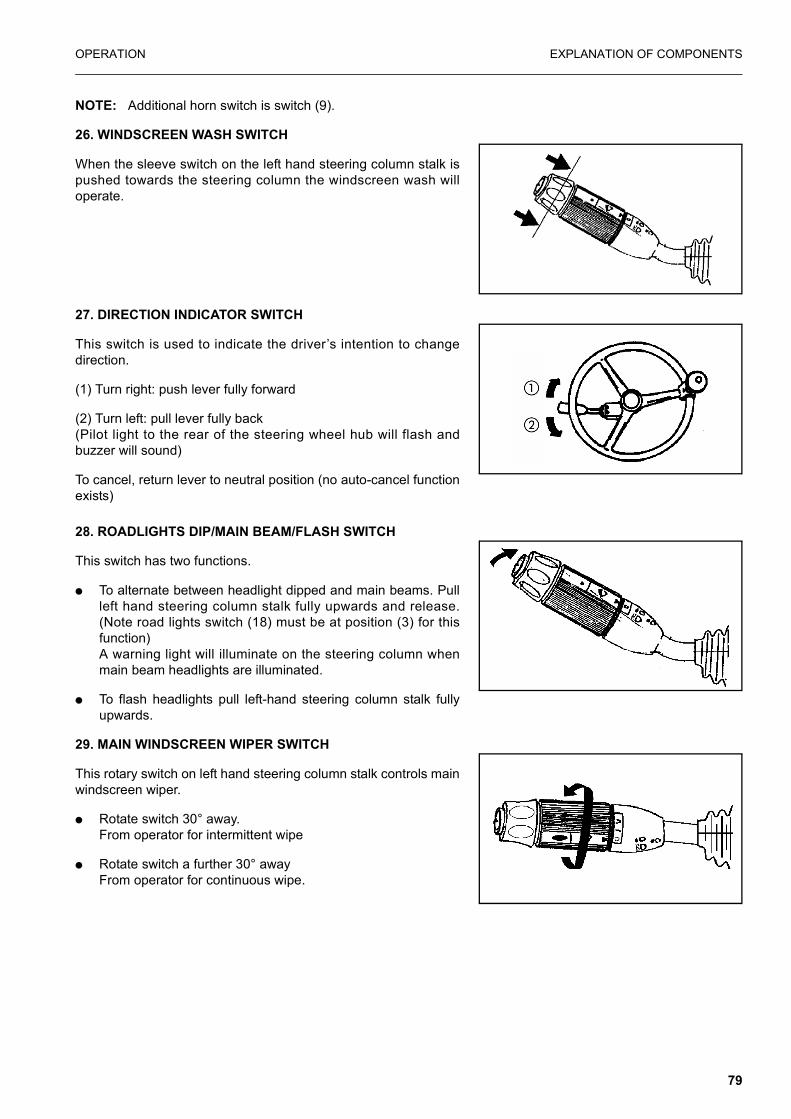
OPERATION EXPLANATION OF COMPONENTS
NOTE: Additional horn switch is switch (9).
26. WINDSCREEN WASH SWITCH
When the sleeve switch on the left hand steering column stalk ispushed towards the steering column the windscreen wash willoperate.
27. DIRECTION INDICATOR SWITCH
This switch is used to indicate the driver’s intention to changedirection.
(1) Turn right: push lever fully forward
(2) Turn left: pull lever fully back(Pilot light to the rear of the steering wheel hub will flash andbuzzer will sound)
To cancel, return lever to neutral position (no auto-cancel functionexists)
28. ROADLIGHTS DIP/MAIN BEAM/FLASH SWITCH
This switch has two functions.
� To alternate between headlight dipped and main beams. Pullleft hand steering column stalk fully upwards and release.(Note road lights switch (18) must be at position (3) for thisfunction) A warning light will illuminate on the steering column whenmain beam headlights are illuminated.
� To flash headlights pull left-hand steering column stalk fullyupwards.
29. MAIN WINDSCREEN WIPER SWITCH
This rotary switch on left hand steering column stalk controls mainwindscreen wiper.
� Rotate switch 30° away.From operator for intermittent wipe
� Rotate switch a further 30° awayFrom operator for continuous wipe.
79

EXPLANATION OF COMPONENTS OPERATION
30. 12V POWER SUPPLY
The 12V socket provided on the right hand panel may be usedonly for electrical accessorIes drawing 1,5 A. maximum. Anyaccessories attached to this socket must carry the EC mark.
CONTROL LEVERS, PEDALS
1. CONTROL LEVER PAD SAFETY LOCK
WARNING
� When leaving the operator’s compartment, switch PPClock switch to off position, raise the control lever pad tothe LOCK position. If the control levers are not locked,and they are touched by mistake, this may lead to a seri-ous accident.If the control lever pad safety lock lever is not placedsecurely in the LOCK position and lock switch is not off,
80

OPERATION EXPLANATION OF COMPONENTS
the control levers may not be properly locked. Check thatthe situation is as shown in the diagram.
� When the control lever pad safety lock lever is raised,take care not to touch the work equipment control lever.If the safety lock lever is not properly locked at the upperposition, the work equipment and swing will move, creat-ing a potentially dangerous situation.
� When the control lever pad safety lock is lowered, takecare not to touch the work equipment control lever.
The control lever pad locks the work equipment, swing andattachment controls.
This device is a hydraulic lock, so even if it is in the lock position,the work equipment control lever will move, but the work equip-ment and swing motor will not work.
2. LEFT WORK EQUIPMENT CONTROL LEVER(with auto-deceleration device)
WARNING
If any lever is operated when in the deceleration range, theengine speed will suddenly increase, so be careful whenoperating the levers.
This lever is used to operate the arm and upper structure.
AM089560A
Arm operation Swing operation
(A) Arm OUT (C) Swing to right
(B) Arm IN (D) Swing to left
N (Neutral)
81

EXPLANATION OF COMPONENTS OPERATION
When the lever in this position, the upper structure and the armwill be retained in the position in which they stop.
3. RIGHT WORK EQUIPMENT CONTROL LEVER(with auto-deceleration device)
WARNING
If an lever is operated when in the deceleration range, theengine speed will suddenly increase, so be careful whenoperating the levers.
This lever is used to operate the boom and bucket.
When the lever in this position, the boom and the bucket will beretained in the position in which they stop.
For levers (2), (3) and (5), the engine speed changes as followsbecause of the auto-deceleration mechanism.
� When the travel lever and work equipment control levers areat neutral, even if the fuel control dial is above the mid-rangeposition, the engine speed will drop to a mid-range speed. Ifany of the levers are operated, the engine speed will rise tothe speed set by the fuel control dial.
� If all control levers are set to neutral, the engine speed willdrop by approx. 100 rpm, and after approx. 4 seconds, theengine speed will drop to the deceleration speed (approx.1400 rpm).
4. PPC LOCK SWITCH
WARNING
When travelling on public roads, set this switch to the offposition. This prevents operation of the work equipment andactivates the rear facing brake lamp circuits.
This switch enables operation of the work equipment controllevers.
ON position (actuated):Operation of the control levers must be disabled by use of thisswitch when the machine is travelling on Public roads.
OFF position (deactivated):The switch is lit in the on (actuated) position.
AM089570A
Boom operation Bucket operation
(1) RAISE (3) DUMP
(2) LOWER (4) CURL
N (Neutral)
82

OPERATION EXPLANATION OF COMPONENTS
5. TRAVEL PEDAL
ROOF HATCH
WARNING
When leaving the operator’s compartment, set the controllever pad safety lock securely to the LOCK position.If the control levers are not locked, and they are touched bymis-take, this may lead to a serious accident.
When opening
1. Lock the safety lock lever securely.
2. Open roof hatch by pulling lock (2) located on both sides,then push up and open the ceiling window grasping grip (1).
When closing
Close the ceiling window grasping grip (1) and lock it with lock (2).If the lock cannot be applied, open and close the ceiling windowagain.
(1) Forward
(2) Neutral
(3 Reverse
83

EXPLANATION OF COMPONENTS OPERATION
CEILING WINDOW
The operator cab is provided with a fixed clear ceiling widow forimproved visibility. An optional guard can be provided for workingin areas at risk from damage.
CLEAR RAIN VISOR
PULL DOWN SUN VISOR
The operator cab is fitted with a pull down sun visor. The visor issimply pulled down and hooked into the retainers mounted on thefront window. The position of the retainers can be adjusted to oneof three pre-set locations by removing the bolts holding the brack-ets, and re-attaching to one of the other prepared locations.
A second set of retainers is positioned at the bottom of the frontwindow to allow coverage of the clear roof when the front windowis in the raised position.
A third set of retainers is fitted to the cab roof to allow coverage ofthe clear roof when the front window is in the normal position.
When the visor is no longer required, remove the shaft from theretainers and allow the blind to return to its’ natural position.
84

OPERATION EXPLANATION OF COMPONENTS
FRONT WINDOW
WARNING
When opening the front window, always hold grip firmly withboth hands and pull up. If you use only one hand, your handmay slip and get caught.
It is possible to store (pull up) the front window (top) in the roof ofthe operator’s compartment.
When opening
WARNING
When the front window is open, there is danger that it willfall, so always lock it with left and right lock pins (A).
1. Place the work equipment on flat ground and stop the engine.
2. Securely lock the control lever pad safety lock.
3. Confirm that the wiper is stored inside the right frame.
85

EXPLANATION OF COMPONENTS OPERATION
4. Pull lock pins (A) at the top left and right sides of the front win-dow to the inside to release the lock.
5. From the inside of the operator’s cab, hold the bottom gripwith the left hand and the top grip with the right hand, pull upthe window, and push it in fully until it is locked by catch (C).
6. Lock with lock pins (A) on the left and right sides.
B
C
AM089670A
A
86

OPERATION EXPLANATION OF COMPONENTS
When closing
WARNING
When closing the window, lower it slowly and be careful notto get your hand caught.
1. Place the work equipment on a flat ground and stop theengine.
2. Securely lock control lever pad safety lock.
3. Release the lock pin (A).
4. Hold the grip at the bottom of the front window with your lefthand and the grip at the top with your right hand, release thelock of catch (C) with your right thumb, then pull the top gripslowly and lower the front window. When releasing the lock of
87

EXPLANATION OF COMPONENTS OPERATION
catch (C), push release lever (D) in the direction of the arrowto release the lock.
5. Lock securely (A) with lock pins at the left and right sides
Removing front window (bottom)
Ensure lower wiper (if fitted) is in correct park position.With the front window open, remove lock pins (E), and the bottompart of the front window can be removed.
Store the removed bottom part of the front window at the rear ofthe operator’s cab and lock with lock pins (E).
NOTICEDo not operate lower wiper (if fitted) when front window
(bottom) is removed.
DOOR LOCKUse the door lock to fix the door in position after opening it.
1. The door will become fixed in place when it is pressed againstcatch (1).
2. To release the lock, press knob (2) down at the left side of theoperator’s seat to release the catch.When fixing the door, fix it firmly to the catch.
B
C
AM089670A
A
AM089730PW
AM089740A
Storage position
88

OPERATION EXPLANATION OF COMPONENTS
CAP, COVER WITH LOCKThe fuel filler, operator’s cab, engine hood, tool box cover, rightside door and left side door of the machine body are fitted withlocks.Use the starting switch key to lock or unlock these places.
METHOD OF OPENING AND CLOSING CAP WITH LOCK (For the fuel tank filler port)
To open the cap
1. Insert the key into the cap.
2. Turn the key clockwise, align the match mark on the cap withthe rotor groove, then remove the cap.
To lock the cap
1. Turn the cap into place.
2. Turn the key and take the key out.
Insert the key as far as it will go. If the key is turned before it isinserted all the way, it may break.
METHOD OF OPENING AND CLOSING COVER WITH LOCK (cover with lock)
To open the cover (locked cover)
1. Insert the key.
2. Turn it counterclockwise and open the cover by pulling thecover grip.
To lock the cover
1. Close the cover and insert the key.
2. Turn the key clockwise and take the key out.
1
2
AW34934D
type A
2
1
3
AW34935D
type B
AAL067870A
89

EXPLANATION OF COMPONENTS OPERATION
FUSENOTE: Before replacing a fuse, be sure to turn off the starting
switch.
The fuses protect the electrical equipment and wiring from burn-ing out.
If the fuse becomes corroded, or white powder can be seen, orthe fuse is loose in the fuse holder, replace the fuse.
Replace a fuse with another of the same capacity.
Fuse capacity and name of circuit
No Fuse capacity Name of circuit
(1) 20 A Pump and governor, breaker switch
(2) 10 A Solenoid valve
(3) 20 A OPT
(4) 10 A LH boom + rear work lamps
(5) 10 ARadio, cigarette lighter, air conditioner panel, heater, windows washer, left knob button
(6) 15 A Horn
(7) 15 A Wiper controller
(8) 20 A Additional (cab) work lamps, beacon
(9) 20 A Lower wiper, refuelling pump
(10) 10 A Key switch signal, heated seat, indica-tors
(11) 20 A Road lights
(12) 30 A Headlights, engine room lamp, hazard
(13) 10 A Alarm signal, monitor
(14) 20 A Start signal
(15) 10 A Cab lamp, radio (back up)
90

OPERATION EXPLANATION OF COMPONENTS
LUGGAGE TRAYThis tray is located to the rear of the operator’s seat. Always keepthe operation & maintenance manual in this box for easy readingaccess.
ASHTRAYThis is on the side of the operator’s seat. Always make sure thatyou extinguish the cigarette before closing the lid.
CUP HOLDER
A cup holder is provided for holding cups or cans. Drinks shouldnot be left in the cup holder whilst operating the machine,because spillage may occur.
HEATER
VIEW OF CONTROL PANEL
1. Inlet air control slider
Change between internal air recirculation & external fresh airintake.
AM089770A
PurposeInternal air circulation.This is used when wishing to quickly warm the cab
External air intake. This is used for fresh air intake or to remove conden-sation on windows or when the air inside the cab is stale
Lever position.AN113590PW
AN113600PW
91

EXPLANATION OF COMPONENTS OPERATION
2. Air outlet selector slider
The operator can select a suitable outlet as required.
For complete defrosting of the front window, set the selector tothe mid-point of its stroke.
3. Temperature control slider
This adjust out air temperatureTo increase temperature of outlet air: move slides to left (red)To decrease temperature of outlet air: move slides to right (blue)
4. Air flow selector switch
This switch adjust air flow in three steps
5. Defroster selector lever
This lever is used to remove condensation or ice from the lowerpart of front window.
Selector lever forward: defrost
Selector lever backward: warms operator’s feet
PurposeSending air to upper area of oper-ator’s seat and defrosting upper part of front window
Sending air to lower area of opera-tor’s seat and de-frosting lower part of front window.
Lever position
Air outlets
AN11550PW AN11560PW
1
2
AA30814C
92

OPERATION EXPLANATION OF COMPONENTS
Defroster is available when air outlet slider is in the positionshown marked:
AIR CONDITIONER
VIEW OF CONTROL PANEL
When a function is activated, the related indicator lamp lights up.
1. AIR OUTLET SELECTOR SWICH
The operator can select a suitable outlet as required.
(1) FEET
(2) DEFROSTER
Purpose Sending air to upper area of operator’s seat
Sending air to lower area of operator’s seat
Switch
93

EXPLANATION OF COMPONENTS OPERATION
2. EXTERNAL/INTERNAL AIR CHANGEOVER SWITCH
Changes between internal air circulation and external air intake.
3. TEMPERATURE CONTROL SWITCH
This switch continuously adjusts the temperature between highand low.
Air outlets
Purpose Sending air to upper area of operator’s seat
Sending air to lower area of operator’s seat
Purpose
Internal air circuit. This is used when wishing to quickly cool or warm the cab or when the air
inside the cab is stale.
External air intakeThis is used for fresh air intake or
to remove condensation on windows
Switch
Purpose To low temperature To high temperature
Switch
Blue range indicates low temperature and red range high temperature.The range is divided into eight steps, each of which is continuously adjustable
AA30813C
Blue Red
94
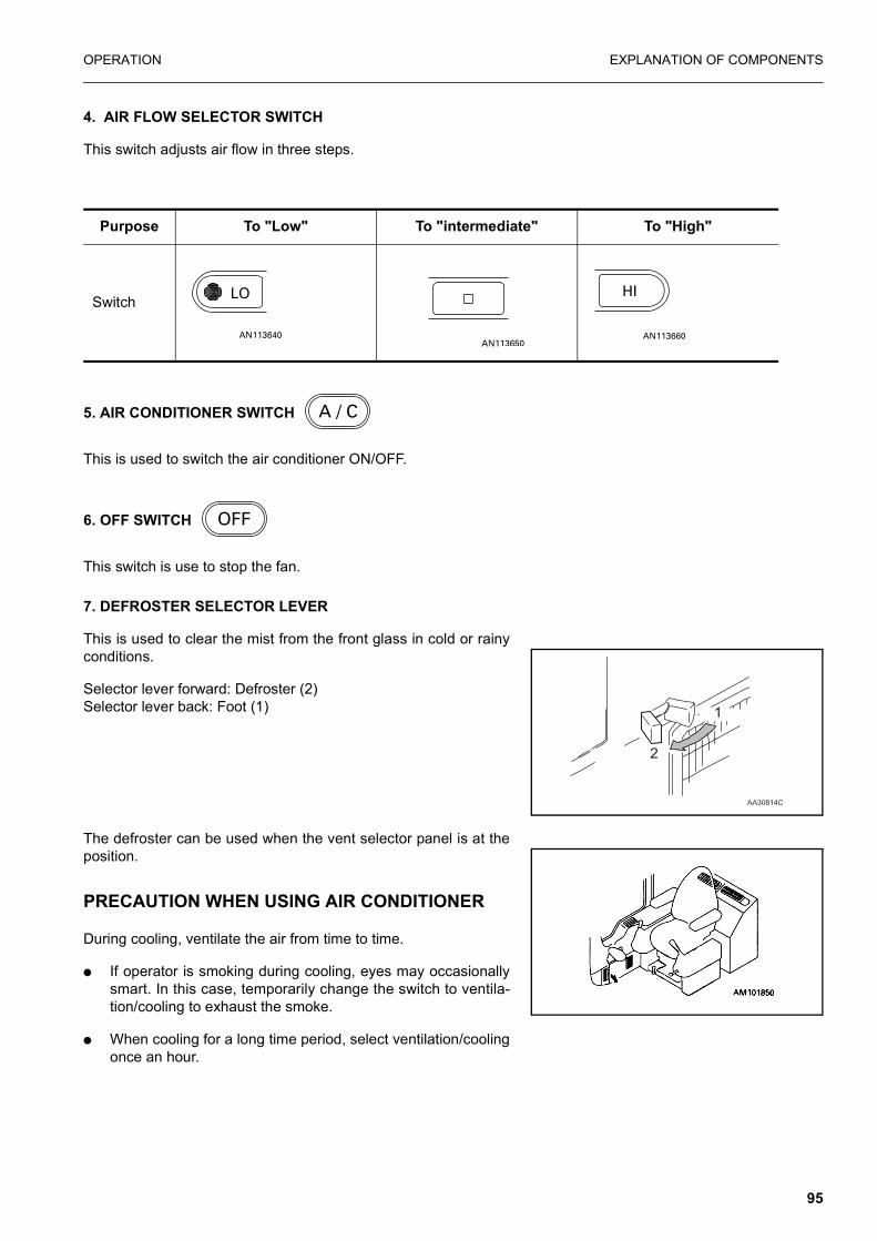
OPERATION EXPLANATION OF COMPONENTS
4. AIR FLOW SELECTOR SWITCH
This switch adjusts air flow in three steps.
5. AIR CONDITIONER SWITCH
This is used to switch the air conditioner ON/OFF.
6. OFF SWITCH
This switch is use to stop the fan.
7. DEFROSTER SELECTOR LEVER
This is used to clear the mist from the front glass in cold or rainyconditions.
Selector lever forward: Defroster (2)Selector lever back: Foot (1)
The defroster can be used when the vent selector panel is at theposition.
PRECAUTION WHEN USING AIR CONDITIONER
During cooling, ventilate the air from time to time.
� If operator is smoking during cooling, eyes may occasionallysmart. In this case, temporarily change the switch to ventila-tion/cooling to exhaust the smoke.
� When cooling for a long time period, select ventilation/coolingonce an hour.
Purpose To "Low" To "intermediate" To "High"
Switch
1
2
AA30814C
95

EXPLANATION OF COMPONENTS OPERATION
Avoiding excessive cooling.
� If the operator feels somewhat cool when entering a cooledcab, the temperature (temperature difference between exter-nal temperature is 5° to 6°C) is at the optimum level from ahealth viewpoint. Adjust the cooling temperature carefully.
FUSIBLE LINKIf the starting motor will not rotate when the starting switch isturned ON, a possible cause is disconnection of wire-type fusiblelink. Open the door on the left side of the machine body to inspectthe fusible link and, if necessary, replace it.
REMARKA fusible link refers to the large-sized fuse wiring installed in
the high current flow portion of the circuit to protect electrical com-ponents and wiring from burning, similar to an ordinary fuse.
CONTROLLERSA pump and governor controller is provided. It is located in theright, rear of the cab underneath panel assy (1).
NOTICE� Never splash or spill water, mud or drink over the con-
troller as this may cause a fault.
� If a fault occurs in the controller, do not attempt repair, but consult your Komatsu distributor.
TOOL BOXThis is used for keeping the tools.
REFUELLING PUMP
WARNING
Do not bring fire or sparks near the fuel.
1. When the machine is operated on sites with no fuel containerand pump, the machine may be refuelled using the refuellingpump (if fitted) from fuel barrels.The refuelling pump is located next to batteries at the frontright hand side of the machine.
2. Place the fuel hose (2), which is stored in tray (3) into the fuelbarrel placed next to the machine.
96

OPERATION EXPLANATION OF COMPONENTS
3. Switch on refuelling pump using switch (1) on the pumpassembly when adding fuel, never let the fuel overflow. Thismay cause a fires.
NOTICE� This pump is protected by a fuse (5). If pump fails to
function check fuse (10A).
� Ensure strainer on hose end is clean.
CAB RADIO (OPTION)Refer to the separate operation manual for radio cassette.
NOTE: Ensure radio is switched off when leaving the machinefor long periods to prevent draining of battery charge.
Antenna
If the reception is weak or generates noise, extend the antenna. Ifthe reception is to strong, adjust the sensitivity by retracting theantenna.
NOTICEWhen transporting the machine or parking it in a garage,
always fully retract the antenna to avoid the possibility ofbreakage.
PRECAUTION OF USE
� To ensure safe operation, adjust the volume level so thatexternal noise is still audible.
� Ensure no water is splashed over the speaker case or cabradio to prevent malfunction.
� Never use solution such as benzine or thinners to clean thedial or buttons. These should be wiped with a dry, soft cloth.(Use a cloth dipping in alcohol for very dirty surfaces.)
� At battery replacement, all the memory pre-set with the pre-set buttons will be cleared. Perform pre-setting again.
AM090050A
97

EXPLANATION OF COMPONENTS OPERATION
WARNING LAMPS
1. INDICATOR WARNING LAMP
This lamp will flash (and buzzer will sound) when indicator lever isnot in neutral.
2. WORKLIGHTS WARNING LAMP
This lamp will illuminate when work lamps are switched on.
3. LOW BRAKE PRESSURE LAMP
When engine is running and brake system hydraulic pressure isabnormal, this lamp will illuminate.
98
OPERATION EXPLANATION OF COMPONENTS
CAUTION
Do not drive machine with low brake pressure warning lamp illuminated.
4. MAIN BEAM WARNING LAMP
This lamp will illuminate when road lights main beam is switchedon.
HANDLING THE ACCUMULATOR
WARNING
After stopping the engine, always place the control lever pad safety lock in the LOCK position and lock the attachment control pedal with the lock pin.
The accumulators are filled with high-pressure nitrogen gas, and it is extremely dangerous if they are handled in the wrong way.Always observe the following precautions.
� Never make any hole in the accumulators or expose themto flame or fire.
� Do not weld any boss to the accumulators.
� When disposing of the accumulators, it is necessary tore lease the gas from the accumulators, so please con-tact your Komatsu distributor.
Brake circuit accumulators
This machine is equipped with the accumulator in the brake cir-cuits.
99

EXPLANATION OF COMPONENTS OPERATION
The accumulator is a device to store the pressure in the circuit,and when it is installed, the circuit can be operated for a shorttime even after the engine is stopped.
The accumulators are installed to the position shown in the dia-gram on the right.
Control circuit accumulator
This machine is equipped with the accumulator in the control cir-cuit. The accumulator is a device to store the pressure in the con-trol circuit, and when it is installed, the control circuit can beoperated for a short time even after the engine is stopped. There-fore, if the control lever is moved in the direction to lower the workequipment, it is possible for the work equipment to move under itsown weight.
The accumulator is installed to the position shown in the diagramon the right.
100
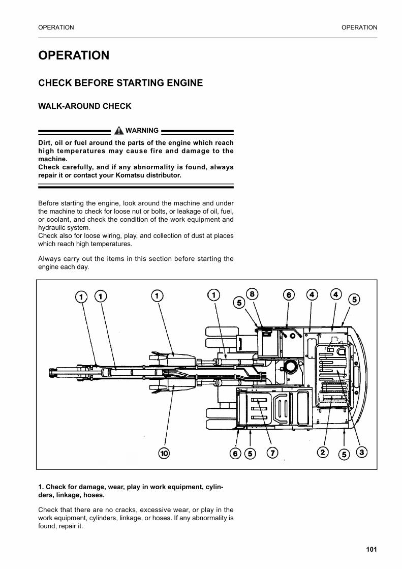
OPERATION OPERATION
OPERATION
CHECK BEFORE STARTING ENGINE
WALK-AROUND CHECK
WARNING
Dirt, oil or fuel around the parts of the engine which reachhigh temperatures may cause fire and damage to themachine.Check carefully, and if any abnormality is found, alwaysrepair it or contact your Komatsu distributor.
Before starting the engine, look around the machine and underthe machine to check for loose nut or bolts, or leakage of oil, fuel,or coolant, and check the condition of the work equipment andhydraulic system.Check also for loose wiring, play, and collection of dust at placeswhich reach high temperatures.
Always carry out the items in this section before starting theengine each day.
1. Check for damage, wear, play in work equipment, cylin-ders, linkage, hoses.
Check that there are no cracks, excessive wear, or play in thework equipment, cylinders, linkage, or hoses. If any abnormality isfound, repair it.
101

OPERATION OPERATION
2. Remove dirt from around engine, radiator
Check that there is no dirt accumulated around the engine or radi-ator. If any dirt is found, remove it.
3. Check for leakage of water or oil around engine
Check that there is no leakage of oil from the engine or leakage ofwater from the cooling system. If any abnormality is found, repairit.
4. Check for oil leakage from hydraulic equipment, hydraulic tank, hoses, joints
Check that there is no oil leakage. If any abnormality is found,repair the place where the oil is leaking.
5. Check for damage to wheels + tyres
6. Check for damage to handrail, loose bolts
Repair any damage and tighten any loose.
7. Check for damage to gauges, monitor, loose bolts
Check that there is no damage to the gauges and monitor in theoperator’s cab. If any abnormality is found, replace the parts.Clean off any dirt on the surface.
8. Clean rear view mirror, check for damage
Check that there is no damage to the rear view mirror. If it is dam-aged, replace it with a new mirror. Clean the surface of the mirrorand adjust the angle so that the view to the rear can be seen fromthe operator’s seat.
9. Check bucket with hook for damage
Check the hook, catcher and hook foot for damage. If damage isfound, contact your Komatsu distributor for repair.
102

OPERATION OPERATION
CHECK BEFORE STARTING
Always carry out the items in this section before starting theengine each day.
CHECK COOLANT LEVEL, ADD WATER
WARNING
Do not open the radiator cap unless necessary. When check-ing the coolant, always check the radiator reserve tank whenthe engine is cold.
1. Open the rear door on the left side of the machine and checkthat the cooling water level is between the FULL and LOWmarks on radiator reserve tank (1)(shown in the diagram onthe right). If the water level is low, add water through thewater filler of reserve tank (1) to the FULL level.
2. After adding water, tighten the cap securely.
3. If the reserve tank becomes empty, first inspect for waterleaks and then fill the radiator and the reserve tank withwater.
CHECK OIL LEVEL IN ENGINE OIL PAN, ADD OIL
1. Open the engine hood.
2. Remove dipstick (G) and wipe the oil off with a cloth.
3. Insert dipstick (G) fully in the oil filler pipe, then take it outagain.
4. The oil level should be between the H and L marks on dipstick(G)
If the oil level is below the L mark, add engine oil through oil filler(F).
For details of the oil to use, see “USE FUEL, COOLANTAND LUBRICANTS ACCORDING TO AMBIENT TEMPER-ATURE” on page 173.
5. If the oil is above the H mark, drain the excess engine oil fromdrain plug (P), and check the oil level again.
6. If the oil level is correct, tighten the oil filler cap securely andclose the engine hood.
REMARKEnsure the machine is level when checking oil level
103

OPERATION OPERATION
WARNING
Allow the engine to cool before checking the oil level toavoid burns by touching hot engine parts.
CHECK FUEL LEVEL, ADD FUEL
WARNING
When adding fuel, never let the fuel overflow. This may causea fire. If spilling fuel, thoroughly clean up any spillage.
1. Use sight gauge (G) on the front face of the fuel tank to checkthat the tank is full.
2. If the fuel level is not within the sight gauge, add fuel throughfiller port (F) while watching sight gauge (G).
104

OPERATION OPERATION
Fuel capacity: 240 l
For details of the fuel to use, see “USE FUEL, COOLANTAND LUBRICANTS ACCORDING TO AMBIENT TEMPER-ATURE” on page 173.
3. After adding fuel, tighten the cap securely.
REMARKIf breather holes (1) on the cap is clogged, the pressure in the
tank will drop and fuel will not flow.Clean the hole from time to time.
CHECK OIL LEVEL IN HYDRAULIC TANK, ADD OIL
WARNING
� When removing the oil filler cap, oil may spurt out, soturn the cap slowly to release the internal pressurebefore removing the cap.
� If oil has been added to above the H mark, stop theengine and wait for the hydraulic oil to cool down, thendrain the excess oil from the drain plug (P).
1. If the work equipment is not in the condition shown in the dia-gram on the right, start the engine, run the engine at lowspeed, retract the arm and bucket cylinders, then lower theboom, set the bucket teeth in contact with the ground, andstop the engine.
2. Check sight gauge (G). The oil level is normal if between theH and L marks.
NOTICEDo not add oil if the level is above the H line. This will
damage the hydraulic equipment and cause oil to spurt out.
105
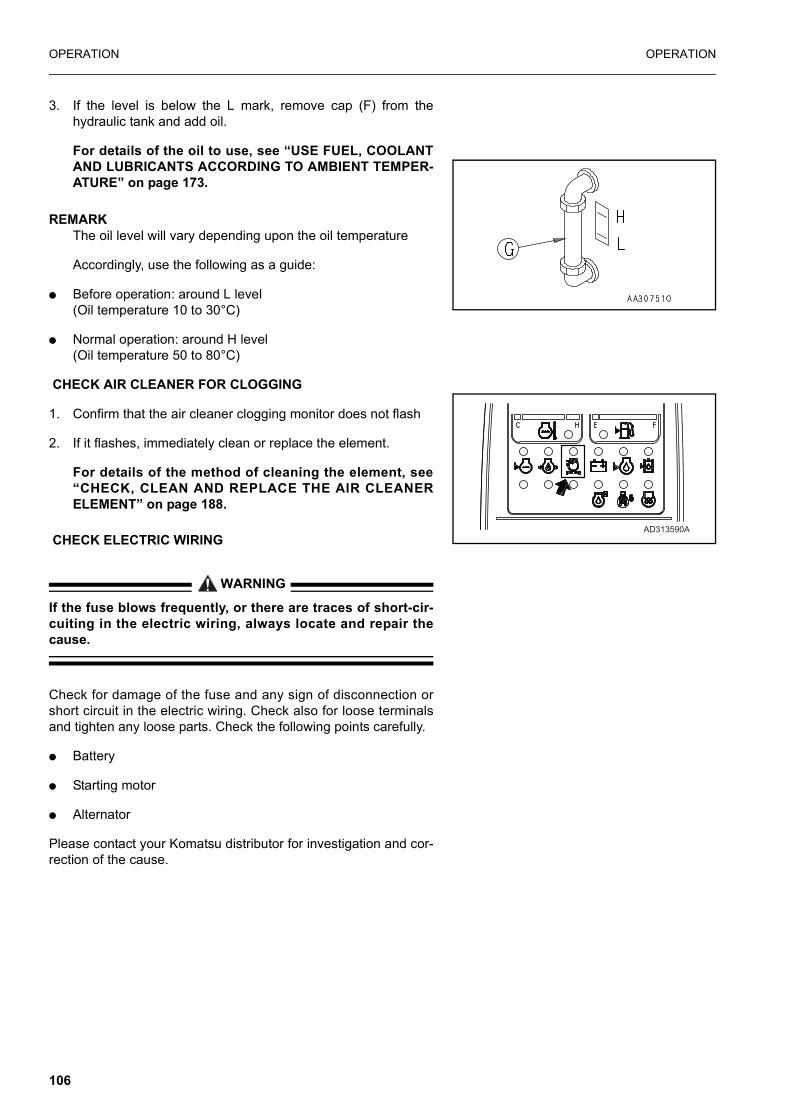
OPERATION OPERATION
3. If the level is below the L mark, remove cap (F) from thehydraulic tank and add oil.
For details of the oil to use, see “USE FUEL, COOLANTAND LUBRICANTS ACCORDING TO AMBIENT TEMPER-ATURE” on page 173.
REMARKThe oil level will vary depending upon the oil temperature
Accordingly, use the following as a guide:
� Before operation: around L level(Oil temperature 10 to 30°C)
� Normal operation: around H level(Oil temperature 50 to 80°C)
CHECK AIR CLEANER FOR CLOGGING
1. Confirm that the air cleaner clogging monitor does not flash
2. If it flashes, immediately clean or replace the element.
For details of the method of cleaning the element, see“CHECK, CLEAN AND REPLACE THE AIR CLEANERELEMENT” on page 188.
CHECK ELECTRIC WIRING
WARNING
If the fuse blows frequently, or there are traces of short-cir-cuiting in the electric wiring, always locate and repair thecause.
Check for damage of the fuse and any sign of disconnection orshort circuit in the electric wiring. Check also for loose terminalsand tighten any loose parts. Check the following points carefully.
� Battery
� Starting motor
� Alternator
Please contact your Komatsu distributor for investigation and cor-rection of the cause.
AD313590A
106

OPERATION OPERATION
CHECK FOR WATER IN FUEL SEDIMENTOR
The fuel sedimentor is mounted in the left hand side compart-ment.
The water separator separates water mixed in the fuel. Before thewater level reaches line (A), drain the water from drain plug (P).
For the draining procedure, see section "WHENREQUIRED".
� Even if a water separator is installed, be sure to check thefuel tank to remove water and sediment in the fuel.
CHECK FOR WATER IN PRIMARY FUEL FILTER, DRAIN WATER
A primary fuel filter is mounted in the radiator compartment.
1. With the engine off open the left hand door and locate thewater drain at the bottom of the primary fuel filter.
2. To open drain valve, turn the valve counterclockwise approxi-mately 1,5 to 2 turns until draining occurs. Drain the filtersump of water until clear fuel is visible.
3. Turn the valve clockwise to close.
NOTICEDo not over tighten the valve. Over tightening can dam-
age the threads.
ADJUSTMENT BEFORE OPERATION OPERA-TOR’S SEAT
(A) Fore-and-aft adjustment of seat
Pull lever (1) up. After the seat is set to the desired position,release the lever.
NOTE: This operation will not affect relative position of seat andwrist control levers.
(B) Forward/aft adjustment of seat
Pull lever (2) up. After the seat is set to the desired positionrelease the lever.
107

OPERATION OPERATION
NOTE: This operation will affect relative position of seat and wristcontrol levers.
(C) Adjustment of reclining seat
Pull lever (3) up after the seat back is set to the optimum positionfor easy operation, release the lever.
(D) Adjustment of arm rest height
Turn thumb wheel (4) to adjust armrest to comfortable height.
(E) Adjustment of tilting seat angle
Lift lever (4) to alter seat angle. Release lever when seat is inrequired position
(F) Suspension adjustment
When knob (6) is turned clockwise, the suspension becomesharder and when turned anti-clockwise, softer. Adjust the dial sothat the suspension best matching the operator ’s weight isselected.
(G) Lumbar adjustment
Turn knob (7) to adjust lumbar supports
(H) Air suspension adjustment (option).
When button 8 is pressed the air compressor will harden the sus-pension, and when the button is pulled out, air is released tosoften the suspension. Note that the compressor can only be acti-vated when the ignition is on.
ADJUSTMENT OF MONITOR PANEL ANGLE
Turn the monitor panel so that the operator can view the monitorwith ease. When adjusting the angle, the panel should be set tothe desired position using both hands. The panel is automaticallylocked at that position.
Amount of adjustment: 30° (stepless)
8
108

OPERATION OPERATION
OPERATIONS AND CHECKS BEFORE STARTING ENGINE
WARNING
If the control lever is touched by accident, the work equip-ment or the machine may move suddenly. When leaving theoperator’s compartment, always set the control lever padsafety lock lever securely to the LOCK position.
1. Check that control lever pad safety lock (1) is at the LOCKposition.
2. Check the position of each lever.
Set the control lever to the neutral position.When starting the engine, never touch the knob button.
3. Insert the key in starting switch (2), turn the key to the ONposition, then carry out the following checks.
The buzzer will sound for approx. 1 sec., and the following moni-tors and gauges will light up for approx. 3 sec.
� Radiator water level monitor (3)
� Engine oil level monitor (4)
� Hydraulic oil level monitor (5)
� Charge level monitor (6)
� Fuel level monitor (7)
� Engine water temperature monitor (8)
� Engine oil pressure monitor (9)
� Engine water temperature gauge (10)
� Fuel gauge (11)
� Engine pre-heating monitor (12)
� Air cleaner clogging monitor (13)
� Swing lock monitor (14)
AM090710A
HEAT OFF
ON
START
AD313610A
109

OPERATION OPERATION
� Replacement monitor of engine oil (15)
If the monitors or gauges do not light up or the buzzer does notsound, there is probably a broken bulb or disconnection in themonitor wiring, so contact your Komatsu distributor for repairs.
After approx. 3 sec., the following gauges will remain on and theother monitors will go out.
� Engine water temperature gauge (10)
� Fuel gauge (11)
(2) Press lamp switch (14) to turn on the work lamps.
A warning lamp on the steering column will illuminate.If the lamps do not light up, there is probably a broken bulb or dis-connection in the wiring, so contact your Komatsu distributor forrepairs.
CAUTION
It is illegal to travel on the road in certain countries with rear-ward facing worklights illuminated.
STARTING ENGINE
NORMAL STARTING
WARNING
Check that there are no persons or obstacles in the sur-rounding area, then sound the horn and start the engine.
NOTICEDo not keep the starting motor rotating continuously for
more than 20 seconds.If the engine will not start, wait for at least 2 minutes beforetrying to start the engine again.
110

OPERATION OPERATION
1. Set fuel control dial (1) at the low idling (MIN) position.
2. Turn the key in starting switch (2) to the START position. Theengine will start.
3. When the engine starts, release the key in starting switch (2).The key will return automatically to the ON position.
STARTING IN COLD WEATHER
WARNING
� Check that there are no persons or obstacles in the sur-rounding area, then sound the horn and start the engine.
� Never use starting aid fluids as they may cause explo-sions.
NOTICEDo not keep the starting motor rotating continuously for
more than 20 seconds.If the engine fails to start, repeat steps from 2 and after wait-ing for about 2 minutes.
When starting in low temperatures, do as follows.
AM090340A
AM090350A
HEAT OFF
ON
ST
AR
T
AM090360A
OFFHEAT
ON
ST
AR
T
AD324280A
111
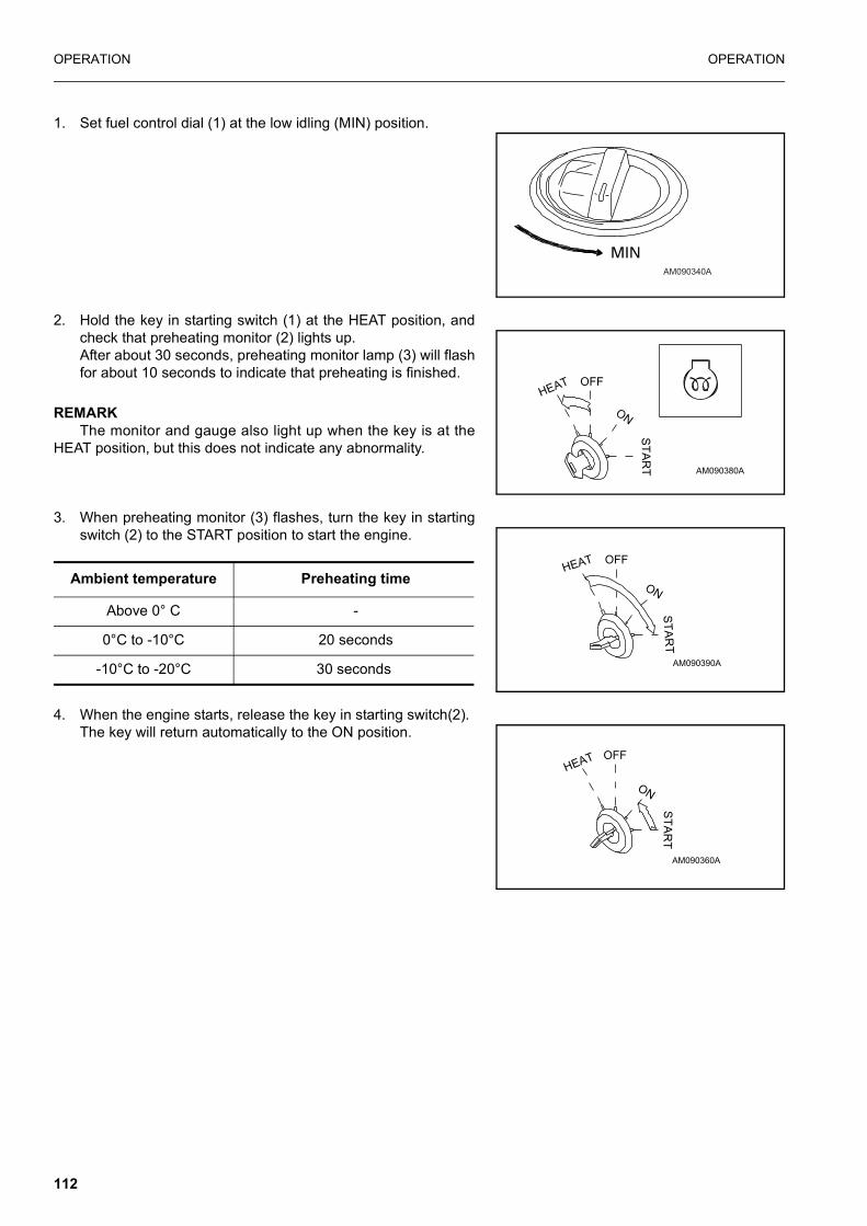
OPERATION OPERATION
1. Set fuel control dial (1) at the low idling (MIN) position.
2. Hold the key in starting switch (1) at the HEAT position, andcheck that preheating monitor (2) lights up.After about 30 seconds, preheating monitor lamp (3) will flashfor about 10 seconds to indicate that preheating is finished.
REMARKThe monitor and gauge also light up when the key is at the
HEAT position, but this does not indicate any abnormality.
3. When preheating monitor (3) flashes, turn the key in startingswitch (2) to the START position to start the engine.
4. When the engine starts, release the key in starting switch(2).The key will return automatically to the ON position.
AM090340A
AM090380A
HEAT OFF
ON
ST
AR
T
AM090390A
HEAT OFF
ON
ST
AR
T
Ambient temperature Preheating time
Above 0° C -
0°C to -10°C 20 seconds
-10°C to -20°C 30 seconds
AM090360A
OFFHEAT
ON
ST
AR
T
112

OPERATION OPERATION
OPERATIONS AND CHECKS AFTER STARTING ENGINE
WARNING
� Emergency stopIf there has been any abnormal actuation or trouble, turnthe starting switch key to the OFF position.
� If the work equipment is operated without warming themachine up sufficiently, the response of the work equip-ment to the movement of the control lever will be slow,and the work equipment may not move as the operatordesires, so always carry out the warming-up operation.Particularly in cold areas, be sure to carry out the warm-ing-up operation fully.
WHEN NORMAL
NOTICE� When the hydraulic oil is at a low temperature, do not
carry out operations or move the levers suddenly. Always carry out the warming-up operation. This will help to extend the machine life.Do not suddenly accelerate the engine before the warm-ing-up operation is completed.
� Do not run the engine at low idling or high idling continu-ously for more than 20 minutes. This will cause leakage of oil from the turbocharger oil supply piping.If it is necessary to run the engine at idling, apply a load from time to time or run the engine at a mid-range speed.
113
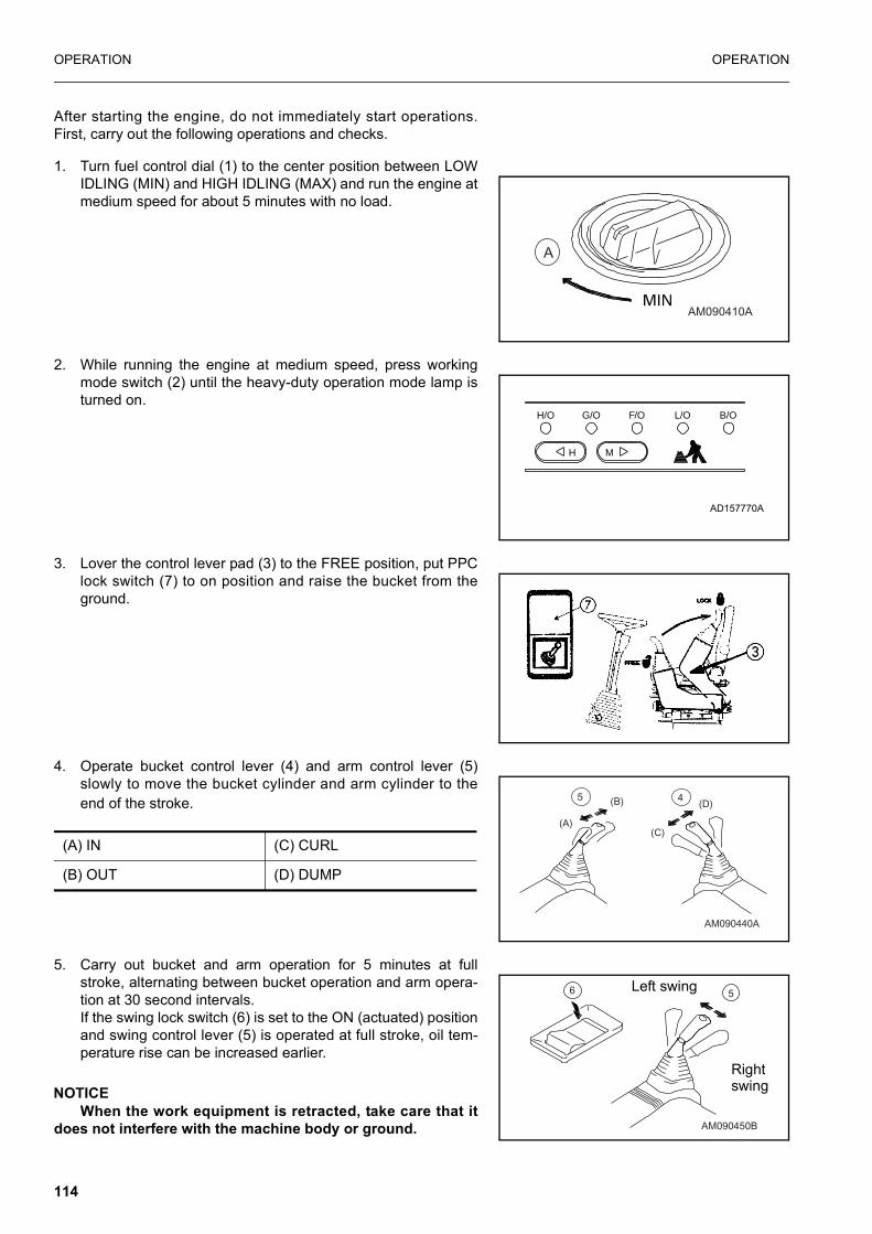
OPERATION OPERATION
After starting the engine, do not immediately start operations.First, carry out the following operations and checks.
1. Turn fuel control dial (1) to the center position between LOWIDLING (MIN) and HIGH IDLING (MAX) and run the engine atmedium speed for about 5 minutes with no load.
2. While running the engine at medium speed, press workingmode switch (2) until the heavy-duty operation mode lamp isturned on.
3. Lover the control lever pad (3) to the FREE position, put PPClock switch (7) to on position and raise the bucket from theground.
4. Operate bucket control lever (4) and arm control lever (5)slowly to move the bucket cylinder and arm cylinder to theend of the stroke.
5. Carry out bucket and arm operation for 5 minutes at fullstroke, alternating between bucket operation and arm opera-tion at 30 second intervals.If the swing lock switch (6) is set to the ON (actuated) positionand swing control lever (5) is operated at full stroke, oil tem-perature rise can be increased earlier.
NOTICEWhen the work equipment is retracted, take care that it
does not interfere with the machine body or ground.
AM090410A
A
AD157770A
H/O G/O F/O L/O B/O
H M
AM090440A
45
(A)
(B)
(C)
(D)
(A) IN (C) CURL
(B) OUT (D) DUMP
6
AM090450B
5Left swing
Right swing
114

OPERATION OPERATION
6. After carrying out the warming-up operation, check that eachgauge and monitor lamp is in the following condition.
� Engine water temperature gauge (7): Inside green range
� Fuel gauge (8): Inside green range
� Engine water temperature monitor (9): OUT
� Radiator water level monitor (10): OUT
� Engine oil pressure monitor (11): OUT
� Charge level monitor (12): OUT
� Fuel level monitor (13): OUT
� Air cleaner clogging monitor (14): OUT
� Engine pre-heating lamp (15): OUT
� Engine oil level monitor (16): OUT
� Hydraulic oil level monitor (17): OUT
� Replacement monitor of engine oil (18): OUT
7. Check that there is no abnormal exhaust gas color, noise, orvibration. If any abnormality is found, repair it.
8. Press working mode switch (2) on the monitor panel until thelamp of the mode to be used lights up.
IN COLD AREAS (AUTOMATIC WARMING-UP OPERATION)
When starting the engine in cold areas, carry out the automaticwarming-up operation after starting the engine.
When the engine is started, if the engine water temperature is low(below 30°), the warming-up operation is carried out automati-cally.
The automatic warming-up operation is cancelled if the enginewater temperature reaches the specified temperature (30°C) or ifthe warming-up operation is continued for 10 minutes. If theengine water temperature or hydraulic oil temperature are lowafter the automatic warming-up operation, warm the engine upfurther as follows.
AD324290A
AD157770A
H/O G/O F/O L/O B/O
H M
115
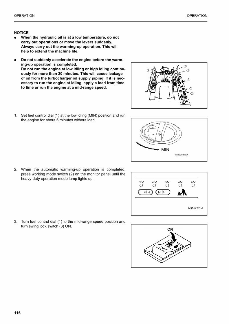
OPERATION OPERATION
NOTICE� When the hydraulic oil is at a low temperature, do not
carry out operations or move the levers suddenly. Always carry out the warming-up operation. This will help to extend the machine life.
� Do not suddenly accelerate the engine before the warm-ing-up operation is completed.Do not run the engine at low idling or high idling continu-ously for more than 20 minutes. This will cause leakage of oil from the turbocharger oil supply piping. If it is nec-essary to run the engine at idling, apply a load from time to time or run the engine at a mid-range speed.
1. Set fuel control dial (1) at the low idling (MIN) position and runthe engine for about 5 minutes without load.
2. When the automatic warming-up operation is completed,press working mode switch (2) on the monitor panel until theheavy-duty operation mode lamp lights up.
3. Turn fuel control dial (1) to the mid-range speed position andturn swing lock switch (3) ON.
AM090340A
AD157770A
H/O G/O F/O L/O B/O
H M
116

OPERATION OPERATION
4. Lower the control lever pad (4) to the FREE position, put PPClock switch (7) to on position and raise the bucket from theground.
5. Operate boom and bucket control lever (5) and arm controllever (6) slowly to operate the boom cylinder, bucket cylinder,and arm cylinder to the end of their stroke.
6. Operate the boom and arm slowly at the same time, andrepeat this for 30 seconds. Next, repeat the same operation with the bucket and swingfor 30 seconds. Operate both fully in turn for 5 minutes.
NOTICEWhen pulling in the work equipment, be careful not to let
it hit the chassis or ground.
7. Turn fuel control dial (1) to the full speed (MAX) position andcarry out the operation is Step 6 for 3 -5 minutes.
8. Repeat the following operation 3 - 5 times and operate slowly.
� Boom operation RAISE ↔ LOWER
� Arm operation IN↔ OUT
� Bucket operation CURL↔ DUMP
� Swing operation LEFT↔ RIGHT
� Travel (Lo) operation FORWARD↔ REVERSE
A Left swing
B Right swing
AN113990A
117

OPERATION OPERATION
REMARKIf the above operation is not carried out, there may be a delay
in response when starting or stopping each actuator, so continuethe operation until it becomes normal.
9. Use working mode switch (2) on the monitor panel to switchto the working mode to be used.
NOTICECancelling automatic warming-up operation
If it becomes necessary in an emergency to lower the enginespeed to low idling, cancel the automatic warming-up opera-tion as follows.
1. Turn fuel control dial (1) to the full speed (MAX) position andhold it for 3 seconds.
2. When fuel control dial (1) is returned to the low idling (MIN)position, the engine speed will drop.
AD157770A
H/O G/O F/O L/O B/O
H M
AM090500A
AN113900A
MINLow idling
118

OPERATION OPERATION
MOVING MACHINE OFF
MOVING MACHINE FORWARD
WARNING
� When moving off, check that the area around themachine is safe, and sound the horn before moving.
� Clear all personnel from the machine and the area.
� Clear all obstacles from the path of the machine.
� If the lever is moved inside the deceleration range,engine speed will rise suddenly. Operate the levers care-fully.
� Ensure that the undercarriage is in the normal forwarddirection
� Check service brake just after moving off.
� Check that low brake pressure warning lamp is off
1. Set swing lock switch (1) to the ON (actuated) position andconfirm that swing lock monitor lamp (2) lights up. Althoughthe hydraulic swing lock ((1) above) may be adequate for nor-mal job site working, it is a legal requirement in some coun-tries to use a mechanical lock when driving on public roads.
2. Turn fuel control dial (3) towards the high idling position toincrease the engine speed.
3. Lower the control lever pad (4) to the FREE position set PPClock switch to on position, fold the work equipment, and raiseit 40 - 50 cm from the ground.
AM090500A
119

OPERATION OPERATION
4. Raise the stabilisers/dozer blade (when fitted). See Sectionon operation of dozer & outriggers section
5. Ensure that the wheel brake is off by depressing servicebrake lock release pedal (5).
6. Release the front axle suspension lock, using switch (6).
Position (1): Front axle suspension travels freely
Position (2): Front axle suspension is in ‘auto’ mode i.e. whentravel pedal is depressed, front axle suspension travels freelyand when travel pedal is not depressed, front axle suspen-sion is locked.
Position (3): Front axle is lockedThe lamp within the switch will illuminate when the front axleis locked, and will not be illuminated when the front axle isunlocked.
NOTE: Where machine is fitted with combination of blade andoutrigger options, it is necessary before dozing opera-tions to position outrigger switch in its central (R.H.Attachment) positions. This is in order to Ensure that thesuspension lock stays in the free position.
7. Set working mode switch to H/O as shown
8. Select travel speed using switch (7). According to the groundconditions and type of operation required, as follows:
Lo mode is for fine control on smooth flat surfaces speed isrestricted to 3.5 km/h (2.7 km/h *).
Mi mode is for traveling on rough surfaces and on steep slopes(up or down), e.g. work sites. Speed is restricted to 10 km/h (8km/h*).
Hi mode is for high speed travel, on smooth surfaces with slopesup to 5 degrees.
B
AA Service brake lock release pedal
B Service brake pedal
AD157770A
H/O G/O F/O L/O B/O
H M
120

OPERATION OPERATION
(e.g. concrete or asphalt roads) maximum speed is available.* (20 km/h specification)
9. Release park brake by using switch (9).
10. Press the travel pedal (10) smoothly. The machine will moveoff in the selected direction.
� If the undercarriage is not facing the normal forward direction- then the travelling direction will be opposite to that which isselected.
� The front (steering) axle has two suspension locking cylindersmounted above the axle. These can be seen clearly from theoperators seat, indicating that the undercarriage is facing inthe normal forward direction.
� Engine speed will automatically reduce 4 seconds afterselecting forward/reverse if no further operation is made. Thissaves fuel consumption (Auto-decel function)
11. When changing direction from forward to reverse or viceversa, always allow the machine to stop before changing theposition of the travel pedal.
12. When travelling in Hi mode a slight shock may occasionallybe heard and/or felt as the automatic transmission clutchoperates. This is normal.
STEERING1. The machine can be steered by turning steering wheel in thedesired direction.
The position of the steering column can be adjusted fore and aftby depressing pedal (2), moving column to desired position andreleasing pedal (2).
121

OPERATION OPERATION
WARNING
� Before shifting between forward and reverse, stop themachine.
If the upper structure is turned 180 degrees (the undercar-riage is re-versed) the machine steers in the opposite direc-tion of the steering wheel. Therefore, take care of the direction of the chassis.
� Before depressing the travel pedal, check the direction ofthe chassis.
� If the travel pedal is fully depressed with the fuel controldial set to max, the machine may start abruptly.
� When driving the machine on a road, raise the outriggersand/or dozer blade and insert the lock pins to preventthem from falling.
� When auto-deceleration is selected, if the wrist controllever or travel pedal is operated inside the decelerationrange, the engine speed will rise suddenly.
� Before moving off turn steering wheel full lock in bothdirections and check wheels turn fully.
� Do not press travel pedal until control pad safety lock isfully down (UNLOCKED).
122

OPERATION OPERATION
STOPPING
STOPPING MACHINE (NORMAL)WARNING
� Avoid stopping suddenly. Give yourself ample roomwhen stopping.
� When stopping the machine, select flat hard ground andavoid dangerous places. If it is unavoidably necessary topark the machine on a slope, insert chocks underneaththe wheels. As an additional safety measure, thrust thebucket into the ground.
� • If the control lever is touched by accident, the workequipment or the machine may move suddenly, and thismay lead to a serious accident. Before leaving the opera-tor’s compartment, always set the control lever padsafety lock securely to the LOCK position.
1. Release the travel pedal (1) and depress the service brakepedal (2) to stop the machine. (The service brakes may belocked by fully de-pressing the service brake pedal until it‘latches’)
2. Lower the work equipment until it touches the ground
3. Raise the control lever pad safety lock to lock the work equip-ment controls (3)
STOPPING MACHINE (EMERGENCY)
The park brake on this machine is a hydraulic-mechanical devicewhich can be used to stop the machine if the service brakes donot work.
In the event of service brake failure;
1. Release travel pedal (1)
2. Depress service brake pedal (2) (to confirm no braking)
3. Brace yourself before engaging emergency brake (A seatbeltis fitted for your safety and comfort. Please wear this at alltimes.)
4. Press park break switch (4) to ‘on’ position, machine will veryquickly come to a halt.
CORRECT
ChockTrust the bucket
123

OPERATION OPERATION
NOTICEThe park brake internal components will be destroyed
during this operation.ONLY USE IT IN AN EMERGENCY.
SWINGING (Slewing the upper carriage)When operating the swing, check that the area around the ma-chine is safe.
1. Before operating the swing, turn swing lock switch (1) OFF(CANCELED).
NOTICECheck that swing lock monitor (2) goes out at the same
time.
2. Operate left work equipment control lever (3) to swing theupper structure.
3. When not operating the swing, turn swing lock switch (1) ON(ACTUATED)
AW349440B
( 1 )
( 2 )
A
B
AM090650A
124
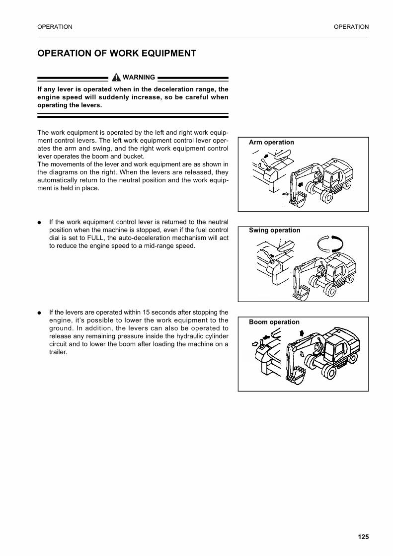
OPERATION OPERATION
OPERATION OF WORK EQUIPMENT
WARNING
If any lever is operated when in the deceleration range, theengine speed will suddenly increase, so be careful whenoperating the levers.
The work equipment is operated by the left and right work equip-ment control levers. The left work equipment control lever oper-ates the arm and swing, and the right work equipment controllever operates the boom and bucket.The movements of the lever and work equipment are as shown inthe diagrams on the right. When the levers are released, theyautomatically return to the neutral position and the work equip-ment is held in place.
� If the work equipment control lever is returned to the neutralposition when the machine is stopped, even if the fuel controldial is set to FULL, the auto-deceleration mechanism will actto reduce the engine speed to a mid-range speed.
� If the levers are operated within 15 seconds after stopping theengine, it’s possible to lower the work equipment to theground. In addition, the levers can also be operated torelease any remaining pressure inside the hydraulic cylindercircuit and to lower the boom after loading the machine on atrailer.
Arm operation
Swing operation
Boom operation
125

OPERATION OPERATION
� 2 pc boom operation
WORKING MODE SELECTION WORKING MODE
The mode selector switches can be used to switch the mode tomatch the conditions and purpose of work, thereby enabling effi-cient operation.Use the following procedures to make the most effective use ofeach mode.
When the starting switch is turned ON, the working mode is set togeneral operation mode (G.O.), so normal work can be carriedout without needing to set the mode.
Set the most effective mode according to the type of work usingworking mode selector switch.
Bucket operation
AD157770A
H/O G/O F/O L/O B/O
H M
Working mode Applicable workPower max. Swift slow-down
(speed down)
Power Speed
Heavy-duty operation mode (H.O.)
Large amount of digging and loading in a short time 8% up Approx. 6% down
General operation mode (G.O.)
Normal digging and loading operation 35% up Approx. 6% down
Finishing operationmode (F.O.)
Finishing, levelling and general hauling operation - -
Lifting operationmode (L.O.) Positioning, etc. - -
Breaker operation mode(B.O.) Breaker operation - -
126

OPERATION OPERATION
NOTICENever carry out breaker operation in heavy-duty opera-
tion mode (H.O.) as this may result in breakage of hydraulicequipment.
POWER MAX./SWIFT SLOW-DOWN
During operation, power up/speed down of work equipment canbe performed by one-touch. Use this function effectively in combi-nation with working mode.
1. When starting switch is turned ON, the power up lamp turnson. When SET switch is pressed once, the speed down lampturns on and the power up lamp goes out, and when pressedagain, the opposite occurs.
2. When the left knob button is given a single click (keepdepressed after initially pressing) power keeps increasingwhile depressed.However, power up automatically completes after 8.5 sec-onds.
AM090710A
HEAT OFF
ON
START
AD157800A
127

OPERATION OPERATION
PROHIBITIONS FOR OPERATION
WARNING
� If it is necessary to operate the work equipment controllever when the machine is traveling, stop the machinebefore operating the work equipment control lever.
� If the lever is moved inside the deceleration range,engine speed will suddenly rise. Operate the levers care-fully.
� Never operate the machine on a rock bed (hard or softrock).
Prohibited operations using swing force
Do not use the swing force to compact soil or break earth moundsor walls.When swinging, do not dig the bucket teeth into the soil. Theseoperations will damage the work equipment.
Prohibited operations using travel force
Do not leave the bucket dug into the ground and use the travelforce to excavate. This will bring excessive force to bear on therear of the machine.
Precautions when operating hydraulic cylinders to end of stroke
If the cylinder is operated to the end of its stroke during opera-tions, force will be brought to bear on the stopper inside the cylin-der, and this will reduce the life of the machine. To prevent this,always leave a small safety margin when operating the cylinders.
INCORRECT
INCORRECT
INCORRECT
128
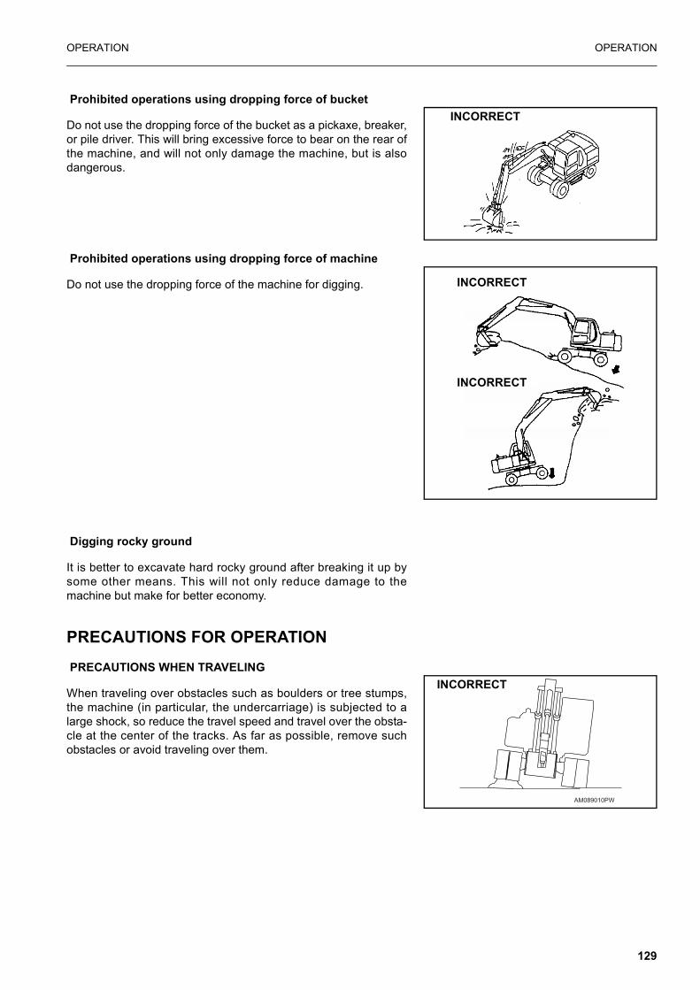
OPERATION OPERATION
Prohibited operations using dropping force of bucket
Do not use the dropping force of the bucket as a pickaxe, breaker,or pile driver. This will bring excessive force to bear on the rear ofthe machine, and will not only damage the machine, but is alsodangerous.
Prohibited operations using dropping force of machine
Do not use the dropping force of the machine for digging.
Digging rocky ground
It is better to excavate hard rocky ground after breaking it up bysome other means. This will not only reduce damage to themachine but make for better economy.
PRECAUTIONS FOR OPERATION PRECAUTIONS WHEN TRAVELING
When traveling over obstacles such as boulders or tree stumps,the machine (in particular, the undercarriage) is subjected to alarge shock, so reduce the travel speed and travel over the obsta-cle at the center of the tracks. As far as possible, remove suchobstacles or avoid traveling over them.
INCORRECT
INCORRECT
INCORRECT
AM089010PW
INCORRECT
129

OPERATION OPERATION
PRECAUTIONS AT Hi-SPEED TRAVEL
On uneven roadbeds such as rock beds or uneven roads withlarge rocks, travel in Mi speedmode and adjust the speed of themachine to prevent loss of control.
PRECAUTIONS WHEN TRAVELLING ON PUBLIC ROADS
When travelling or public roads the control lever pad safety lockshould be down and the control lever lock switch, in the off posi-tion. This prevents operation of the control levers and activatesthe rear facing brake lamp circuit.
PERMISSIBLE WATER DEPTH
Do not immerse the machine in water by more than the permissi-ble depth (axle centre).In addition, for parts that have been immersed in water for a longtime, pump in grease until the old grease comes out from thebearings. (Around the bucket pins).
PRECAUTIONS WHEN TRAVELING UP OR DOWN HILLS
WARNING
� When traveling, raise the bucket approx. 20 - 30 cm fromthe ground.Do not travel downhill in reverse.
� When traveling over ridges or other obstacles, keep thework equipment close to the ground and travel slowly.
� It is dangerous to turn on slopes or to travel acrossslopes. Always go down to a flat place to perform theseoperations. It may be longer, but it will ensure safety.
� If the machine starts to slide or loses stability, lower thebucket immediately and brake the machine.
� Turning or operating the work equipment when workingon slopes may cause the machine to lose its balance andturn over, so avoid such operations. It is particularly dan-gerous to swing downhill when the bucket is loaded.If such operations have to be carried out, pile soil tomake platform on the slope so that the machine can bekept horizontal when operating.
� Do not travel on slopes of over 30° as there is danger thatthe machine may overturn.
AD145900A
INCORRECT
CORRECT
INCORRECT CORRECTPlatform
130

OPERATION OPERATION
1. When traveling down steep hills, keep the travel speed low.When traveling down slopes of more than 15°, set the workequipment in the posture shown in the figure on the right, andlower the engine speed.
2. When travelling down hills of more than 5° first stop, engagethe service brake and select Mi travel mode. Release the ser-vice brake and proceed (full hydraulic braking will than beavailable).
3. When traveling up a steep hill of more than 15°, set the workequipment in the posture shown in the diagram on the right.
If engine stops
If the engine stops when traveling uphill, lower the bucket to theground, stop the machine, then start the engine again.
Precautions on slopes
� If the engine stops when the machine is on a slope, never usethe left work equipment control lever to carry out swing opera-tions. The upper structure will swing under its own weight.
� Do not open or close the door on the cab if the machine is ona slope. This may cause a sudden change in the operatingforce. Always keep the door locked.
HOW TO ESCAPE FROM MUDAlways operate carefully to avoid getting stuck in mud. If the ma-chine does get stuck in mud, use the following procedures to getthe machine out.
WHEN ONE SIDE IS STUCK
When only one side is stuck in mud, use the bucket to raise thewheels then lay boards or logs and drive the machine out. If nec-essary, put a board under the bucket also.
NOTICEWhen using the boom or arm to raise the machine,
always have the bottom of the bucket in contact with theground. (Never push with the teeth). The angle between theboom and arm should be 90° to 110°.The same applies when using the inverting bucket.
Downhill
Uphill
131

OPERATION OPERATION
WHEN BOTH SIDES ARE STUCK
When all wheels are stuck in mud and the machine will not move,lay boards as explained above, and dig the bucket into the groundin front. Then pull in the arm as in normal digging operations andput the travel levers in the FORWARD position to pull the machineout.
WORK POSSIBLE USING HYDRAULIC EXCAVATORIn addition to the following, it is possible to further increase therange of applications by using various attachments.
BACKHOE WORK
When condition of the machine is as shown in the diagram atright, each cylinders maximum pushing excavation force isobtained when the bucket cylinder and link, arm cylinder and armare at 90°.
When excavating, use this angle effectively to optimize your workefficiency.The range for excavating with the arm is from a 45° angle awayfrom the machine to a 30° toward the machine.
There may be some differences depending on the excavationdepth, but try to use within the above range rather than going allthe way to the extreme end of the cylinder stroke.
SHOVEL WORK
A shovel is suitable for excavating at a position higher than themachine. Shovel work is performed by attaching the bucket in thereverse direction.
132

OPERATION OPERATION
DITCHING WORK
Ditching work can be performed efficiently by attaching a bucketto match the width of the ditch and then setting the wheels parallelto the line of the ditch to be excavated.To excavate a wide ditch, first dig out both sides and then finallyremove the center portion.
LOADING WORK
In places where the swing angle is small, work efficiency can beenhanced by locating the dump truck in a place easily visible tothe operator.Loading is easier and capacity greater if you begin from the frontof the dump truck body than if loading is done from the side.
REPLACEMENT AND INVERSION OF BUCKET
WARNING
� When knocking the pin in with a hammer, metal particlesmay fly and cause serious injury, particularly if they getinto your eyes. When carrying out this operation, alwayswear goggles, helmet, gloves, and other protectiveequipment.
� When the bucket is removed, place it in a stable condi-tion.
Stop the machine on a firm, flat surface. When performing jointwork, make clear signals to each other and work carefully forsafety’s sake.
REPLACEMENT
1. Place the bucket in contact with a flat surface.
REMARKWhen removing the pins, place the bucket so that it is in light
contact with the ground.
AM090950A
Bucket cylinder
Arm
Link
133
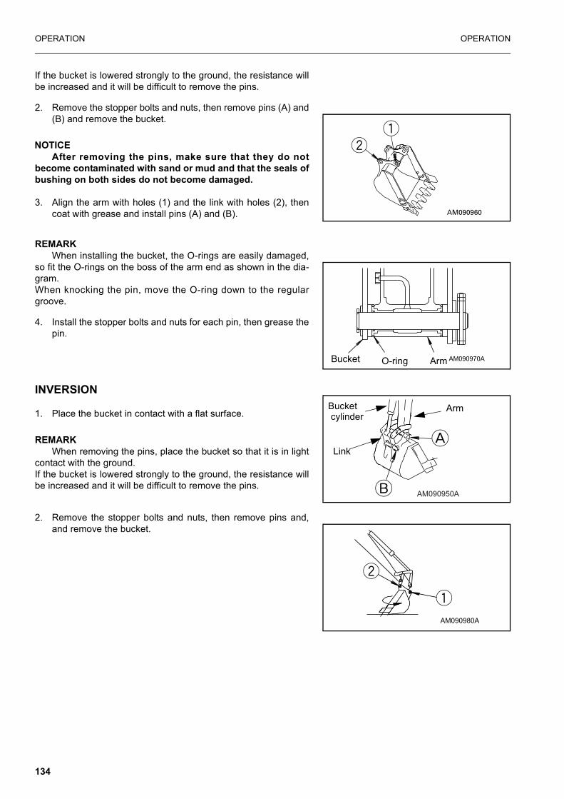
OPERATION OPERATION
If the bucket is lowered strongly to the ground, the resistance willbe increased and it will be difficult to remove the pins.
2. Remove the stopper bolts and nuts, then remove pins (A) and(B) and remove the bucket.
NOTICEAfter removing the pins, make sure that they do not
become contaminated with sand or mud and that the seals ofbushing on both sides do not become damaged.
3. Align the arm with holes (1) and the link with holes (2), thencoat with grease and install pins (A) and (B).
REMARKWhen installing the bucket, the O-rings are easily damaged,
so fit the O-rings on the boss of the arm end as shown in the dia-gram. When knocking the pin, move the O-ring down to the regulargroove.
4. Install the stopper bolts and nuts for each pin, then grease thepin.
INVERSION
1. Place the bucket in contact with a flat surface.
REMARKWhen removing the pins, place the bucket so that it is in light
contact with the ground.If the bucket is lowered strongly to the ground, the resistance willbe increased and it will be difficult to remove the pins.
2. Remove the stopper bolts and nuts, then remove pins and,and remove the bucket.
AM090970ABucket O-ring Arm
AM090950A
Bucket cylinder
Arm
Link
AM090980A
134

OPERATION OPERATION
NOTICEAfter removing the pins, make sure that they do not
become contaminated with sand or mud and that the seals ofbushing on both sides do not become damaged.
3. Install the bucket inversely.After the bucket is inversed, correct the inclination and direc-tion of the retaining pin holes (1) and (2) and stabilise thebucket securely.
4. Align the arm with holes (1) and the link with holes (2), thencoat with grease and install pins (A) and (B).
REMARKInstall the O-rings into retaining hole (1) of the arm and
bucket.
When installing the bucket, the O-rings are easily damaged, so fitthe O-rings on the boss of the arm end as shown in the diagram.When knocking the pin, move the O-ring down to the regulargroove.
5. Install the stopper bolts and nuts for each pin, then grease thepin.
AM090990A
AM090970ABucket O-ring Arm
135

OPERATION OPERATION
PARKING MACHINE
WARNING
� Avoid stopping suddenly. Give yourself ample roomwhen stopping.
� When stopping the machine, select flat hard ground andavoid dangerous places. If it is unavoidably necessary topark the machine on a slope, insert chocks underneaththe wheels. As an additional safety measure, thrust thebucket into the ground.
� If the control lever is touched by accident, the workequipment or the machine may move suddenly, and thismay lead to a serious accident. Before leaving the opera-tor’s compartment, always set the control lever padsafety lock lever securely to LOCK position.
1. Depress the brake pedal (1) until machine stops.
2. Turn fuel control dial (2) to lower the engine speed to lowidling.
ChockTrust the bucket
AM090340A
136

OPERATION OPERATION
3. Operate park brake by using switch(4).
4. Lower the bucket horizontally until the bottom touches theground.
5. Set control lever pad safety lock (3) to the LOCK position.
CHECK AFTER FINISHING WORKCheck the engine water temperature, engine oil pressure and fuellevel on the monitor.
STOPPING ENGINE
NOTICEIf the engine is abruptly stopped before it has cooled
down, engine Iife may be greatly shortened. Consequently,do not abruptly stop the engine apart from an emergency.In particular, if the engine has overheated, do not abruptlystop it but run it at medium speed to allow it to cool gradu-ally, then stop it.
1. Run the engine at low idling speed for about 5 minutes toallow it to gradually cool down.
2. Turn the key in starting switch (1) to the OFF position andstop the engine.
3. Remove the key from starting switch (1).
AM089160A
HEAT OFF
ON
ST
AR
T
137

OPERATION OPERATION
CHECK AFTER STOPPING ENGINE1. Walk around the machine and check the work equipment,
paint work, and undercarriage, and check also for leakage ofoil or water. If any abnormalities are found, repair them.
2. Fill the fuel tank.
3. Check the engine compartment for paper and debris. Cleanout any paper and debris to avoid a fire hazard.
4. Remove any mud stuck to the undercarriage.
LOCKINGAlways lock the following places.
REMARKUse the starting switch key to open and close all these
places.
OVERLOAD WARNING DEVICEExcavators are provided with this device to warn the operatorabout tipping over while lifting loads. A buzzer will sound whenthe machine is in LO mode. and the machine nears its liftingcapacity
NOTE: Only conduct lifting operations in LO mode as the over-load warning system is only active in this mode.
HANDLING THE WHEELS
WARNING
Incorrect handling of wheels and tyres can result in seriousinjury or death.Particular care is required when working on twin wheelassemblies.
(1) Door of operator’s cab.Always remember to close the window.
(2) Fuel tank filler port
(3) Engine hood
(4) Tool box cover
(5) Battery room door (left side of machine)
138

OPERATION OPERATION
Before any attempt is made to remove the road wheels thetyres must be fully deflated.
1. General information
� Always replace damaged parts with new parts from yourKomatsu distributor.Never attempt to repair damaged items.
� Use the appropriate tools in a good condition to remove thevarious pieces of the rim. Never use metallic hammer, use amallet with a face made from Rubber, Plastic or Copper.
� On machines fitted with twin wheel assemblies a valve exten-sion is fitted to the inner wheel to facilitate deflation. This partshould always be refitted following disassembly as it ensuresthat the inner wheel assembly can be deflated whilst fitted tothe hub.
2. Before starting to remove the wheels
1. Depress the brake pedal fully until it locks.
2. Raise the chassis with the boom so that the tyres are raisedabove the ground. Then, place axle stands below the frontand rear axles.
3. Loosen wheel nuts with a wheel wrench. Wheel nuts haveR.H. threads.
4. Proceed in accordance with the following procedure, payingattention to the information specific to the type of wheelassembly fitted to the machine on which you are working.
Tyre pressure: 10.00 - 20 14 ply tyres (Twin assy)
Front wheel: 6.75 Bar Rear wheel: 6.75 Bar
Tyre pressure: 18 R 19.5 (Single) Tyres
Front wheel: 8.0 Bar Rear wheel: 8.0 Bar
139

OPERATION OPERATION
WARNING
Failure to observe the following procedure may result in seri-ous injury or death.
3. Twin wheel assembly - 3 part rim
Deflation and removal:
� Before loosening the wheel retaining nuts, completely deflatethe tyres by removing the valve with the appropriate tool.Always stand to the side during the deflating operation.
� Release 8 of the wheel retaining nuts leaving 2 diagonallyopposed nuts to hold the assembly in position. Check thatthere is no remaining pressure being exerted on these rema-ing nuts by either the internal or external wheel assembly.Once satisfied that the remaining nuts are under no pressure,remove them.
� In order to remove the tyre from the rim first remove the lock-ring by progressively levering it from the gutter (groove). Donot exert excessive force as this may deform the retainingring.
� Remove the loose flange and then the tyre/tube.
Re - assembly & inflation
� Check thoroughly the condition of the wheel and rim for signsof wear or damage. Discard any defective or doubtful parts and replace withapproved replacement parts.Clean the rims with a hard brush paying particular attention tothe bottom of the rim gutter (groove).
� Fit the tyre to the rim base and fit the tube, ensuring that thevalve is correctly located in its through hole.
� Place the loose flange against the tyre bead in the orientationshown in Fig. 1. Push it into place sufficient to clear the rimgutter (groove) to enable the lock-ring to be fitted.
A B
C
D
A Rim Base
B Loose flange
C Lockring
D Rim Gutter (groove)
140

OPERATION OPERATION
� Insert the lock-ring with the aid of specific tools or with leversand a suitable mallet. Check correct seating of the lock-ringby measuring the dimension of the gap shown in Fig. 2.
If it is not possible to achieve the stated gap with the lock-ringseated correctly renew the rim assembly.
WARNING
It is essential that the lock-ring is seated correctly.
� Put the wheel assembly into a safety cage and inflate the tyreto a pressure of 1 - 1.5 Bar.
� Visually check the lock-ring is still seated correctly and thereis no clearance between it and the loose flange Fig. 3.
� If the lock-ring is not in the correct position stop the procedureas the lock-ring may be ejected from the groove resulting inpossible injury. Deflate the tyre and repeat the procedure.If the lock-ring is correctly positioned continue to inflate thetyre to the value given in the previous table.
� Before removing the wheel assembly from the safety cagerepeat the visual check.
� When refitting the wheel assemblies, tighten at least 2 diago-nally opposite wheel nuts and then tighten the tyres to thespecified torque in the order shown in Fig. 4.Tightening torque: 450 Nm
� Retighten to the specified torque after 5 hours operation.
YES CORRECT ASSEMBLY
Clearance
NO WRONG ASSEMBLY
141
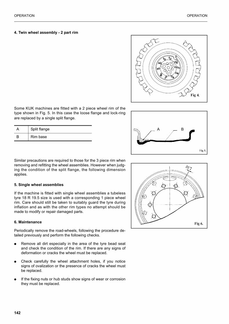
OPERATION OPERATION
4. Twin wheel assembly - 2 part rim
Some KUK machines are fitted with a 2 piece wheel rim of thetype shown in Fig. 5. In this case the loose flange and lock-ringare replaced by a single split flange.
Similar precautions are required to those for the 3 piece rim whenremoving and refitting the wheel assemblies. However when judg-ing the condition of the split flange, the following dimensionapplies.
5. Single wheel assemblies
If the machine is fitted with single wheel assemblies a tubelesstyre 18 R 19.5 size is used with a corresponding 1 piece wheelrim. Care should still be taken to suitably guard the tyre duringinflation and as with the other rim types no attempt should bemade to modify or repair damaged parts.
6. Maintenance
Periodically remove the road-wheels, following the procedure de-tailed previously and perform the following checks.
� Remove all dirt especially in the area of the tyre bead seatand check the condition of the rim. If there are any signs ofdeformation or cracks the wheel must be replaced.
� Check carefully the wheel attachment holes, if you noticesigns of ovalization or the presence of cracks the wheel mustbe replaced.
� If the fixing nuts or hub studs show signs of wear or corrosionthey must be replaced.
A BA Split flange
B Rim base
142

OPERATION OPERATION
7. Wheel spacer
WARNING
Wheel spacers must not be used with radial ply tyres.
8. Rotating tyres
Consult your local Komatsu distributor for advice on rotating tyres.
143

TRANSPORTATION OPERATION
TRANSPORTATION
When transporting the machine, observe all related laws and reg-ulations, and be careful to assure safety.
LOADING, UNLOADING WORK
WARNING
� Loading or unloading the machine can be a dangerousoperation, so be particularly careful.When loading or unloading the machine, run the engineat low idling and travel at low speed.
� Make sure the ramp has sufficient width, length andthickness to enable the machine to be safely loaded andunloaded. If the ramp sags appreciably, reinforce it withblocks, etc.
� When loading and unloading the machine, park the traileron a flat firm roadbed. Keep a fairly long distancebetween the road shoulder and the machine.
� Remove the mud from the undercarriage to prevent themachine from slipping to the side on slopes.Be sure the ramp surface is clean and free of grease, oil,ice and loose materials.
� Never change the direction of travel when on the ramps.If it is necessary to change direction, drive off the rampsand correct the direction, then drive on to the rampsagain.
� When turning the machine on the trailer, the machine’sfooting is unstable, so carry out the operation slowly.
� Always check that the door on the cab is locked, regard-less of whether it is open or closed. Do not open or close the door on ramps or on a platform.This may cause a sudden change in the operating force.
� When loading or unloading the machine with the auto-matic warming-up operation mode, if the automatic modeis released, the speed may change suddenly. Avoid load-ing or unloading during automatic warming-up operation.
144

OPERATION TRANSPORTATION
When loading or unloading, always use ramps or a platform andcarry out the operations as follows.
1. Properly apply the brakes on the trailer and insert blocks(2)beneath the tyres to ensure that it does not move. Then fixthe ramps in line with the centers of the trailer and themachine. Be sure that the two sides are at the same level asone another.
Make the angle of the ramps (3) a maximum of 15°.
Set the distance between the ramps (A) to match the center of thewheels.
2. Set the travel speed switch to the Mi position.
3. Turn the auto-deceleration switch OFF, and return the fuelcontrol dial to reduce the engine speed.
4. Turn the swing lock switch ON to apply the swing lock.
5. Set in the direction of the ramps, lower the work equipment asfar as possible without letting it hit the trailer, then travelslowly to load or unload the machine.
When on the ramps, do not operate any lever other than the travellever.
6. Load the machine correctly in the specified position on thetrailer.
REMARKWhen the work equipment is installed, load the machine from
the front; when the work equipment is not installed, load themachine from the rear.
AD052900A
(3)
(2)
(A)
(1)
AD157790A
AD157780A
145

TRANSPORTATION OPERATION
PRECAUTIONS FOR LOADING
WARNING
When loading the machine, park the trailer on a flat firm road-bed. Keep a fairly long distance between the road shoulderand the machine.
After loading to the specified position, secure the machine as fol-lows.
1. Fully extend the bucket and arm cylinders, then slowly lowerthe boom.
2. Stop the engine and remove the key from the starting switch.
3. Lock all the control levers securely with the control lever padsafety lock.
4. When transporting the machine, place rectangular timberunderneath the front and rear wheels to prevent the machinefrom moving about. Also, hold it down with chains or rope. Beparticularly careful to ensure that the machine does not slipsideways.
NOTICEWhen transporting the machine, place rectangular timber
under one end of the bucket cylinder to prevent it touchingthe ground, thereby saving it from possible damage.
HOW TO LIFT THE MACHINE
Personnel who perform lifting using a crane must be qualified.
146

OPERATION TRANSPORTATION
WARNING
Contact your distributor to get instructions of lifting amachine. Some parts are required and are available asoptional parts.
WARNING
� Do not lift a vehicle with personnel in it.
� The rope used for lifting must have sufficient strength towith stand the weight of this machine.
� The machine must not be in a position other than thatshown in the following procedure when lifting a vehicle.Otherwise, the machine may be unbalanced.
Lifting a machine must be performed on a flat place with the fol-lowing procedure.
1. Start the engine and set the machine in the position shown inthe figure at the right (boom at the top stroke end, arm bucketfully retracted). Direct the top revolving super-structurestraight forward.
2. Set the control lever pad safety lock in the lock position.
3. Stop the engine. Confirm safety around the operator seat.Get off the machine.Be sure to close the cab door, windshield, right and left doors,engine hood, etc.
4. Mount a shackle to the lifting hook on the boom and thecounter weight. Hang the wire rope.
5. The length off the wire rope and the lifting angle must be asshown in the figure on the right.
6. When lifting, make sure that there is no change in the positiondue to possible leakage in the hydraulic circuit on the boomcylinder head side.
7. When the machine leaves the ground, stop the machine andmake sure sufficiently that the machine is balanced.Then, lift the machine slowly.
Lifting points
147

TRANSPORTATION OPERATION
PRECAUTIONS FOR TRANSPORTATION
WARNING
� Determine the route for transporting the machine by tak-ing into account the width, height and weight of themachine.
� Always check that the door on the cab is closed andlocked before transporting the machine.
NOTICEAlways retract the car radio antenna.
Obey all state and local laws governing the weight, width andlength of a load. Observe all regulations governing wide loads.
(1) Height for transport = (2) Overall height + (3) height of trailerplatform
* Weights and dimensions: will vary according to specification.
Consult your Komatsu distributor if in doubt.
SpecificationsOverall
length (A) (mm)
Overall width (B)
(mm)
Overall height (mm)
* Weight Kg
1 piece boom 7600 2490 3080 12200
2 piece boom 7800 2490 3080 13100
148

OPERATION TRANSPORTATION
TRAVELLING POSTUREBefore starting to travel, be sure to pull in and lock the outriggers,and/or raise the dozer blade.
Before travelling on public roads, the work equipment should bepositioned as follows.
1. Position the upper structure so that it is facing the front of theundercarriage (the oscillation lock cylinders can be seen) andinsert the swing lock pin.
2. Fully extend the bucket cylinder.
3. Fully extend the first boom cylinders.
4. Fully extract the second boom cylinders.
5. Adjust the arm cylinder such that the boom and arm pointersare aligned.
6. Disable the work equipment levers by moving the controllever pad safety lock to the locked position.
7. Close manual lock valves
1) For the bucket cylinder, located on the arm.
2) For the arm cylinder, located on the first boom.
After setting the machine in the travelling posture, confirm that itsoverall height is below 4m and that the distance between the cen-tre of the steering wheel and the front of the work equipment isless than 3.5 m.
Before moving off, lock all machine cover and toolbox doors toprevent accidental opening.
Green zoneRed zone
149
COLD WEATHER OPERATION OPERATION
COLD WEATHER OPERATION
PRECAUTIONS FOR LOW TEMPERATUREIf the temperature becomes low, it becomes difficult to start theengine, and the coolant may freeze, so do as follows.
FUEL AND LUBRICANTS
Change to fuel and oil with low viscosity for all components. Fordetails of the specified viscosity, see “USE FUEL, COOLANTAND LUBRICANTS ACCORDING TO AMBIENT TEMPERA-TURE” on page 173.
COOLANT
Keep antifreeze fluid away from an open flame. Never smokewhen using antifreeze.
NOTICE� • Never use methanol, ethanol or propanol based anti-
freeze.
� Absolutely avoid using any water leak preventing agent irrespective of whether it is used independently or mixed with an antifreeze.
� Do not mix one antifreeze with a different brand.
For details of the antifreeze mixture when changing thecoolant, see see “WHEN REQUIRED” on page 188.
Use a Permanent Antifreeze (ethylene glycol mixed with corro-sion inhibitor, antifoam agent, etc.) meeting the standard require-ments as shown below. With permanent antifreeze, no change ofcoolant is required for a year. If it is doubtful that an available anti-freeze meets the standard requirements, ask the supplier of thatantifreeze for information.
Standard requirements for permanent antifreeze
� SAE.............................................................................. J1034
� FEDERAL STANDARD........................................... O-A-548D
REMARKWhere no permanent antifreeze is available, an ethylene gly-
col antifreeze without corrosion inhibitor may be used only for thecold season. In this case, clean the cooling system twice a year(in spring and autumn). When refilling the cooling system, addantifreeze in autumn, but do not add any in spring.
150
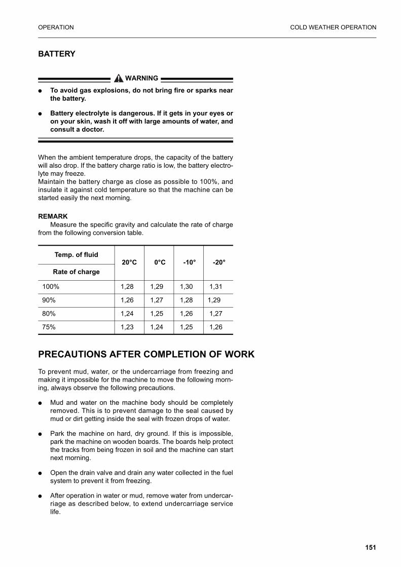
OPERATION COLD WEATHER OPERATION
BATTERY
WARNING
� To avoid gas explosions, do not bring fire or sparks nearthe battery.
� Battery electrolyte is dangerous. If it gets in your eyes oron your skin, wash it off with large amounts of water, andconsult a doctor.
When the ambient temperature drops, the capacity of the batterywill also drop. If the battery charge ratio is low, the battery electro-lyte may freeze.Maintain the battery charge as close as possible to 100%, andinsulate it against cold temperature so that the machine can bestarted easily the next morning.
REMARKMeasure the specific gravity and calculate the rate of charge
from the following conversion table.
PRECAUTIONS AFTER COMPLETION OF WORKTo prevent mud, water, or the undercarriage from freezing andmaking it impossible for the machine to move the following morn-ing, always observe the following precautions.
� Mud and water on the machine body should be completelyremoved. This is to prevent damage to the seal caused bymud or dirt getting inside the seal with frozen drops of water.
� Park the machine on hard, dry ground. If this is impossible,park the machine on wooden boards. The boards help protectthe tracks from being frozen in soil and the machine can startnext morning.
� Open the drain valve and drain any water collected in the fuelsystem to prevent it from freezing.
� After operation in water or mud, remove water from undercar-riage as described below, to extend undercarriage servicelife.
Temp. of fluid20°C 0°C -10° -20°
Rate of charge
100% 1,28 1,29 1,30 1,31
90% 1,26 1,27 1,28 1,29
80% 1,24 1,25 1,26 1,27
75% 1,23 1,24 1,25 1,26
151

COLD WEATHER OPERATION OPERATION
� As the battery capacity drops markedly in low temperatures,cover the battery or remove it from the machine, keep it in awarm place, and install it again the next morning.
� If electrolyte level is found low, add distilled water in the morn-ing before beginning work. Do not add the water after theday’s work so as to prevent fluid in the battery from freezing inthe night.
AFTER COLD WEATHERWhen season changes and the weather becomes warmer, do asfollows.
� Replace the fuel and oil for all parts with oil of the viscosityspecified.
For details, see “USE FUEL, COOLANT AND LUBRI-CANTS ACCORDING TO AMBIENT TEMPERATURE” onpage 173.
� If for any reason permanent antifreeze cannot be used, andan ethyl glycol base antifreeze (winter, one season type) isused instead, or if no antifreeze is used, drain the cooling sys-tem completely, then clean out the inside of the cooling sys-tem thoroughly, and fill with fresh water.
152
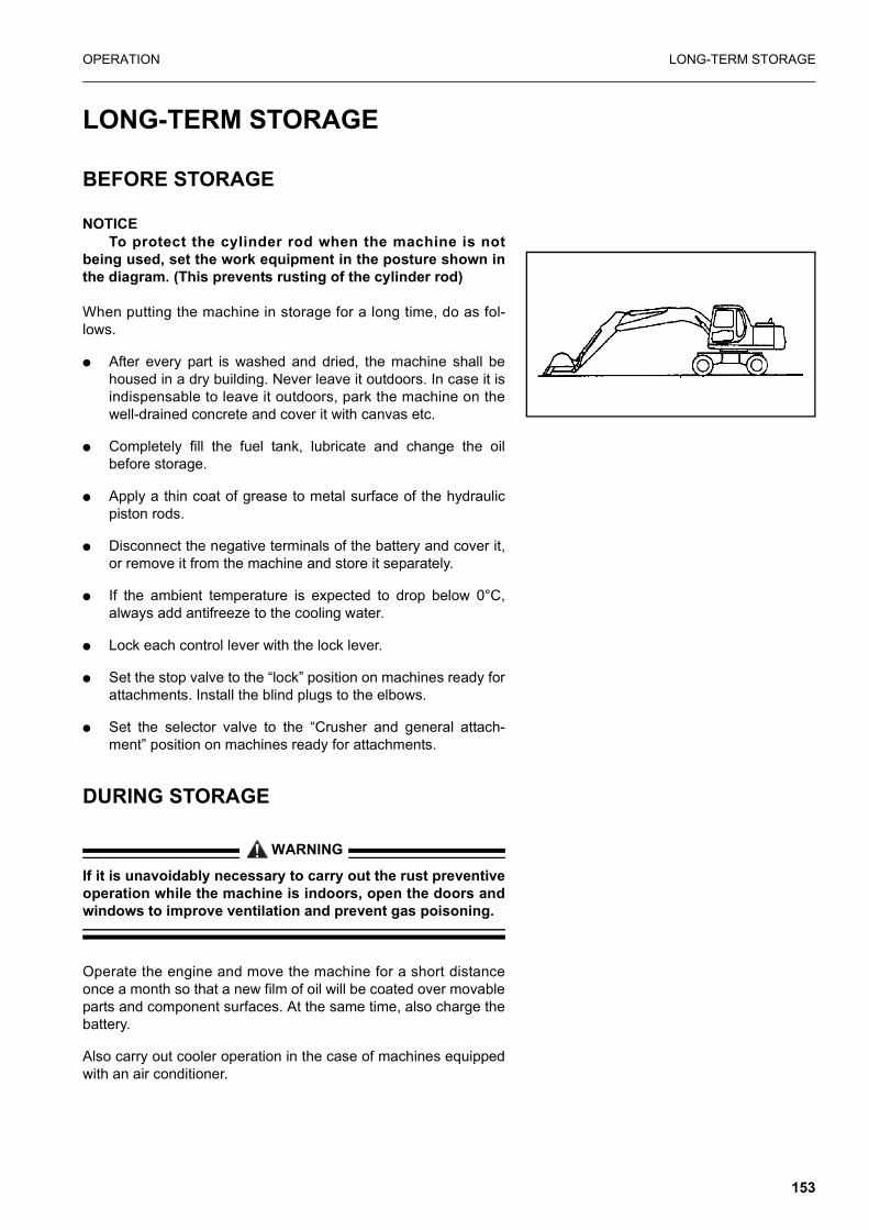
OPERATION LONG-TERM STORAGE
LONG-TERM STORAGE
BEFORE STORAGE
NOTICETo protect the cylinder rod when the machine is not
being used, set the work equipment in the posture shown inthe diagram. (This prevents rusting of the cylinder rod)
When putting the machine in storage for a long time, do as fol-lows.
� After every part is washed and dried, the machine shall behoused in a dry building. Never leave it outdoors. In case it isindispensable to leave it outdoors, park the machine on thewell-drained concrete and cover it with canvas etc.
� Completely fill the fuel tank, lubricate and change the oilbefore storage.
� Apply a thin coat of grease to metal surface of the hydraulicpiston rods.
� Disconnect the negative terminals of the battery and cover it,or remove it from the machine and store it separately.
� If the ambient temperature is expected to drop below 0°C,always add antifreeze to the cooling water.
� Lock each control lever with the lock lever.
� Set the stop valve to the “lock” position on machines ready forattachments. Install the blind plugs to the elbows.
� Set the selector valve to the “Crusher and general attach-ment” position on machines ready for attachments.
DURING STORAGE
WARNING
If it is unavoidably necessary to carry out the rust preventiveoperation while the machine is indoors, open the doors andwindows to improve ventilation and prevent gas poisoning.
Operate the engine and move the machine for a short distanceonce a month so that a new film of oil will be coated over movableparts and component surfaces. At the same time, also charge thebattery.
Also carry out cooler operation in the case of machines equippedwith an air conditioner.
153

LONG-TERM STORAGE OPERATION
AFTER STORAGE
NOTICEIf the machine is stored without carrying out the monthly
rust prevention operation, request your Komatsu distributorfor service.
Carry out the following procedure when taking the machine out oflong-term storage.
� Wipe off the grease from the hydraulic cylinder rods.
� Add oil and grease to all places.
STARTING MACHINE AFTER LONG-TERM STORAGEWhen starting the machine after a long-term storage, first cancelthe automatic warming-up function as follows.
1. Turn the starting switch key to the ON position.
2. Turn the fuel control dial from the low idling (MIN) position tothe full (MAX) position, hold it there for 3 seconds, then returnit to the low idling (MIN) position and start the engine.
154
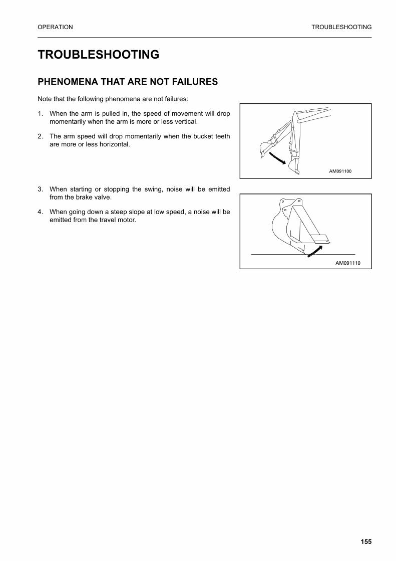
OPERATION TROUBLESHOOTING
TROUBLESHOOTING
PHENOMENA THAT ARE NOT FAILURESNote that the following phenomena are not failures:
1. When the arm is pulled in, the speed of movement will dropmomentarily when the arm is more or less vertical.
2. The arm speed will drop momentarily when the bucket teethare more or less horizontal.
3. When starting or stopping the swing, noise will be emittedfrom the brake valve.
4. When going down a steep slope at low speed, a noise will beemitted from the travel motor.
155

TROUBLESHOOTING OPERATION
METHOD OF TOWING MACHINE
WARNING
When towing the machine, use a wire rope that has amplestrength for the weight of the machine that is being towed.
If the machine sinks in mud and cannot get out under its ownpower, or if the drawbar pull of the excavator is being used to towa heavy object, use a wire rope as shown in the diagram.
WHEN USING THE FRONT OF CHASSIS
WHEN USING THE REAR OF THE CHASSIS
PRECAUTIONS ON PARTICULAR JOBSITES1. When carrying out digging operations in water, if the work
equipment mounting pin goes into the water, carry out greas-ing every time the operation is carried out.
2. For heavy-duty operations and deep digging, carry out greas-ing of the work equipment mounting pins every time beforeoperation.
3. After greasing, operate the boom, arm and bucket severaltimes, then grease again.
156

OPERATION TROUBLESHOOTING
IF BATTERY IS DISCHARGED
WARNING
� When checking or handling the battery, stop the engineand turn the starting switch key to the OFF positionbefore starting.
� The battery generates hydrogen gas, so there is dangerof explosion. Do not bring lighted cigarettes near the bat-tery, or do anything that will cause sparks.
� Battery electrolyte is dilute sulphuric acid, and it willattack your clothes and skin. If it gets on your clothes oron your skin, wash it immediately with large amounts ofwater. If it gets in your eyes, wash it out with fresh water,and consult a doctor.
� When handling battery, always wear protective goggles.
� When removing the battery, first disconnect the cablefrom the ground (normally, from the negative (-) termi-nal). When installing, install the positive (+) terminal first.If a tool touches the cable connecting the positive (+) ter-minal and the chassis, there is danger that it will causesparks.
� If the terminals are loose, there is danger that the defec-tive contact may generate sparks that will cause anexplosion.
� When installing the terminals, install them tightly.
� When removing or installing, check which is the positive(+) terminal and negative (-) terminal.
STARTING ENGINE WITH BOOSTER CABLE
When starting the engine with a booster cable, do as follows:
AD052940A
When removingdisconnect the cable from the ground terminalfirst
When installing, connect the cable tothe positive (+)terminal first.
INCORRECT
157

TROUBLESHOOTING OPERATION
Precautions when connecting and disconnecting booster cable
WARNING
� When connecting the cables, never contact the positive(+) and negative (-) terminals.
� When starting the engine with a booster cable, alwayswear safety glasses.
� Be careful not to let the normal machine and problemmachine contact each other. This prevents sparks fromgenerating near the battery which could ignite the hydro-gen gas given off by the battery. If hydrogen gasexplodes, it could cause serious injury.
� Make sure that there is no mistake in the booster cableconnections. The final connection is to the revolvingframe, but sparks will be generated when this is done, soconnect to a place as far as possible from the battery.(However, avoid connecting the cable to the work equip-ment, as conduction is poor.)
� Use care when removing the cables from the machinethat has been started. Do not allow the cable ends to con-tact each other or the machine, to avoid hydrogen explo-sion.
NOTICE� The size of the booster cable and clip should be suitable
for the battery size.
� The battery of the normal machine must be the same capacity as that of the engine to be started.
� Check the cables and clips for damage or corrosion.
� Make sure that the cables and clips are firmly connected.
Connecting the booster cables
Keep the starting switch at the OFF position.Connect the booster cable as follows, in the order of the numbersmarked in the diagram.
1. Make sure that the starting switches of the normal machineand problem machine are both at the OFF position.
2. Connect one clip of booster cable (A) to the positive (+) termi-nal of the problem machine.
3. Connect the other clip of booster cable (A) to the positive (+)terminal of the normal machine.
4. Connect one clip of booster cable (B) to the negative (-) termi-nal of the normal machine.
AD052980A
158

OPERATION TROUBLESHOOTING
5. Connect the other clip of booster cable (B) to the engine blockof the problem machine.
Starting the engine
1. Make sure the clips are firmly connected to the battery termi-nals.
2. Start the engine of the normal machine and keep it to run athigh idling speed.
3. Turn the starting switch of the problem machine to the STARTposition and start the engine. If the engine doesn’t start atfirst, try again after 2 minutes or so.
Disconnecting the booster cables
After the engine has started, disconnect the booster cables in thereverse of the order in which they were connected.
1. Remove one clip of booster cable (B) from the engine block ofthe problem machine.
2. Remove the other clip of booster cable (B) from the negative(-) terminal of the normal machine.
3. Remove one clip of booster cable (A) from the positive (+) ter-minal of the normal machine.
4. Remove the other clip of booster cable (A) from the positive(+) terminal of the problem machine.
OTHER TROUBLE
ELECTRICAL SYSTEM
� ( ): Always contact your Komatsu distributor when dealingwith these items.
� In cases of abnormalities or causes which are not listedbelow, please contact your Komatsu distributor for repairs.
AD052981A
Problem Main causes Remedy
Lamp does not glow brightly even when the engine runs at high speed
� Defective wiring
� Defective adjustment of fan belt tension
� (Check, repair loose terminals, disconnections)
� Adjust fan belt tension For details, see EVERY 250 HOURS SERVICE
Lamp flickers while engine is run-ning
Charge level monitor does not go out even when engine is running
� Defective alternator� Defective wiring
� (Replace)� (Check, repair)
Abnormal noise is generated from alternator � Defective alternator � (Replace)
159

TROUBLESHOOTING OPERATION
CHASSIS
� ( ): Always contact your Komatsu distributor when dealingwith these items.
� In cases of abnormalities or causes which are not listedbelow, please contact your Komatsu distributor for repairs.
ENGINE
� ( ): Always contact your Komatsu distributor when dealingwith these items.
Starting motor does not turn when starting switch is turned to ON
� Defective wiring� Insufficient battery charge
� (Check, repair)� Charge
Pinion of starting motor keeps going in and out � Insufficient battery charge � Charge
Starting motor turns engine slug-gishly
� Insufficient battery charge� Defective starting motor
� Charge� (Replace)
Starting motor disengages before engine starts
� Defective wiring� Insufficient battery charge
� (Check, repair)� Charge
Pre-heating monitor does not light � Defective wiring� Defective heater relay� Defective monitor
� (Check, repair)� (Replace)� (Replace)
Oil pressure monitor does not light up when engine is stopped (start-ing switch at ON position)
� Defective monitor� Defective caution lamp
� (Replace)� (Replace)
Outside of electrical heater is not is warm when touched by hand
� Defective wiring� Disconnection in electric heater� Defective operation of heater
relay switch
� (Check, repair)� (Replace)� (Replace)
Problem Main causes Remedy
Problem Main causes Remedy
Speed of travel, swing, boom, arm, bucket is slow
� Lack of hydraulic oil
� Add oil to specified level, see CHECK BEFORE STARTING
Pump generates abnormal noise � Clogged element in hydraulic tank strainer
� Clean, see EVERY 2000 HOURS SERVICE
Excessive rise in hydraulic oil tem-perature
� Loose fan belt
� Dirty oil cooler
� Lack of hydraulic oil
� Check fan belt tension, see EVERY 1000 HOURS SERVICE
� Clean, see EVERY 500 HOURS SERVICE
� Add oil to specified level, see CHECK BEFORE STARTING
Bucket rises slowly, does not rise � Lack of hydraulic oil � Add oil to specified level, see CHECK BEFORE STARTING.
160
OPERATION TROUBLESHOOTING
� In cases of abnormalities or causes which are not listedbelow, please contact your Komatsu distributor for repairs.
Problem Main causes Remedy
Engine oil pressure monitor lights up
� Engine oil pan oil level is low (sucking in air)
� Clogged oil filter cartridge
� Defective tightening of oil pipe joint, oil leakage from damaged part
� Defective engine oil pressure sensor
� Add oil to specified level, see CHECK BEFORE STARTING
� Replace cartridge, see EVERY 250 HOURS SERVICE
� (Check, repair)
� (Replace sensor)
Steam is emitted from top part of radiator (pressure valve) � Cooling water level low, water
leakage� Loosen fan belt� Dirt or scale accumulated in
cooling system� Clogged radiator fin or dam-
aged fin� Defective thermostat� Loose radiator filler cap (high
altitude operation)� Defective water level sensor
� Add cooling water, repair, see CHECK BEFORE STARTING
� Adjust fan belt tension, see EVERY 250 HOURS SERVICE
� Change cooling water, clean inside of cooling system, see WHEN REQUIRED
� Clean or repair, see EVERY 500 HOURS SERVICE
� (Replace thermostat)� Tighten cap or replace packing� (Replace sensor)
Radiator water level monitor lights up
Engine does not start when start-ing motor is turned.
� Lack of fuel
� Air in fuel system� Defective fuel injection pump or
nozzle� Starting motor cranks engine
sluggishly� Preheating monitor does not
light up� Defective compression� Defective valve clearance
� Add fuel, see CHECK BEFORE STARTING
� Repair place where air is sucked in, see EVERY 500 HOURS SERVICE
� (Replace pump or nozzle)
� See ELECTRICAL SYSTEM
� (Adjust valve clearance)
Exhaust gas is white or blue� Too much oil in oil pan
� Improper fuel
� Add oil to specified level, see CHECK BEFORE STARTING
� Change to specified fuel
Exhaust gas occasionally turns black
� Clogged air cleaner element
� Defective nozzle� Defective compression
� Defective turbocharger
� Clean or replace, see WHEN REOUIRED
� (Replace nozzle)� (See defective compression
above)� Clean or replace turbo-charger
Combustion noise occasionally makes breathing sound � Defective nozzle � (Replace nozzle)
Abnormal noise generated (com-bustion or mechanical).
� Low grade fuel being used� Overheating
� Damage inside muffler� Excessive valve clearance
� Change to specified fuel� Refer to “Radiator water level
monitor lights up” as above� (Replace muffler)� (Adjust valve clearance)
161

TROUBLESHOOTING OPERATION
ELECTRONIC CONTROL SYSTEM
If an error code appears on the machine monitor display (normallydisplays TIME), follow the countermeasure table as shown belowin the self-diagnosis.
Machine monitor trouble display
(*) For detail of operating the pump override switch and the swingoverride switch, refer to "SWITCHES"
Monitor display Error mode Countermeasure
E02 TVC valve system error
If the pump override switch is set to the ON posi-tion, operation can be carried out. However, immediately have the TVC valve system inspected by your Komatsu distributor. (*)
E03 Swing brake system error
Set the swing override switch to the ON position to release the brake. If applying the swing brake, manually operate the swing brake using the swing holding brake switch. In this case, immedi-ately have the swing brake system inspected by your Komatsu distributor. (*)
E05 Governor system error
Governor will not execute the control function. Manually operate the governor-lever. To fix the governor lever at the full stroke position, use the retaining bolt holes on bracket. In this case, immediately have the governor system inspected by your Komatsu distributor.
CALL Error indicating that operation can-not be continued
Place the machine in a safe posture, then have it inspected immediately by your Komatsu distribu-tor.
In the case where the monitor will not display error codes and work equipment operation and swing operation cannot be carried out.
Have the machine inspected immediately by your Komatsu distributor.
162

MAINTENANCE.
163

GUIDES TO MAINTENANCE MAINTENANCE.
GUIDES TO MAINTENANCE
Do not carry out any inspection and maintenance operation that is not given in this manual.
Perform maintenance work on hard, flat ground.
Check service meter:
Check the service meter reading every day to see if the time hascome for any necessary maintenance to be carried out.
Komatsu genuine replacement parts:
Use Komatsu genuine parts specified in the Parts Book asreplacement parts.
Komatsu genuine oils:
Use Komatsu genuine oils and grease. Choose oils and greasewith proper viscosities specified for ambient temperature.Always use clean washer fluid:Use automobile window washer fluid and be careful not to let anydirt get into it.
Always use clean oil and grease:
Use clean oil and grease. Also, keep containers of the oil andgrease clean. Keep foreign materials away from oil and grease.
Keeping the machine clean:
Always keep the machine clean. This makes is easier to find partscausing problems. Keep in particular grease fittings, breathersand oil level gauges clean and avoid foreign matters from gettingin them.
Be careful of hot water and oil:
Draining hot oils and coolants and removing their filters immedi-ately after the engine stops are hazardous. Allow the engine tocool.
If the oil has to be drained when it is cold, warm up the oil to asuitable temperature (approx. 20 - 40°C) before draining it.
Checking foreign materials in drained oil and on filter:
After oil is changed or filters are replaced, check the oil and filtersfor metallic particles and foreign materials. If large quantities ofmetallic particles or foreign materials are found, consult yourKomatsu distributor.
Fuel strainer:
If your machine is equipped with a fuel strainer, do not remove itwhile fueling.
164
MAINTENANCE. GUIDES TO MAINTENANCE
Oil change:
Check or change oils in the places where dust is scarce to keepforeign materials away from oils.
Warning tag:
Attach the warning tag to the starting switch or other appropriatecontrol lever to avoid someone who is not aware of the circum-stances from starting the engine.
Obey precautions:
During the operation, always obey the precautions on the safetylabel attached to the machine.
Welding instructions:
� Turn off the engine starting switch.
� Do not apply more than 200 V continuously.
� Connect grounding the cable within 1 m from the area to bewelded.
� Avoid seals or bearings from being between the area to bewelded and the position of roundin
� Do not use the area around the work equipment pins or thehydraulic cylinders as the grounding point.
Fire prevention
Use nonflammable cleaner or light oil for cleaning parts. Keepflame or cigarette light away from light oil.
Clamp faces:
When O-rings or gaskets are removed, clean the clamp faces andreplace the 0-rings and gaskets with new ones.Be sure to fit 0-rings and gaskets when assembling.
Objects in your pockets:
Keep your pockets free of loose objects which can fall out anddrop into the machinery; especially when you work on themachinery while bending over it.
Checking undercarriage:
When working in rocky areas, check for damage to the undercar-riage and for looseness, flaws, wear and damage in bolts andnuts. Loosen the track tension a little when working in such areas.
Precautions when washing machine:
� Never spray steam or water directly on the connectors andmechatronics parts.
165

GUIDES TO MAINTENANCE MAINTENANCE.
� Do not allow water to get on the monitors and controllersinside the operator’s cab.
� Never spray steam or water directly at the radiator or oilcooler portions.
Pre-and post-work checks:
Before starting work in mud, rain, snow or at seashore, checkplugs and valves for tightness. Wash the machine immediatelyafter the work to protect components from rusting. Lubricate com-ponents more frequently than usual.Be sure to lubricate work equipment pins daily if they are sub-merged in water.
Dusty worksites:
When working at dusty worksites, do as follows:
� Inspect the air cleaner clogging monitor to see whether the aircleaner is blocked. Clean the air cleaner at shorter intervalsthan specified.
� Clean the radiator core frequently to avoid clogging.
� Clean and replace the fuel filter frequently.
� Clean electrical components, especially the starting motorand alternator, to avoid accumulation of dust.
Avoid mixing oils:
Never mix oils of different brands. If you have only oil which is adifferent brand from the one that is used in the machine, do notadd it but replace all the oil.
166

MAINTENANCE. OUTLINES OF SERVICE
OUTLINES OF SERVICE
� Use Komatsu genuine parts for replacement.
� When changing or adding oil, do not use a different type of oil.
� Unless otherwise specified, the oil and coolant used at thetime of shipment from the factory are as shown in the tablebelow.
OUTLINE OF OIL, FUEL, COOLANT
OIL
� Oil is used in the engine and work equipment under extremesevere conditions (high temperature, high pressure), and itdeteriorates with use.Always use oil that matches the grade and temperature foruse given in the Operation and Maintenance Manual. Even ifthe oil is not dirty, always replace the oil after the specifiedinterval.
� Oil corresponds to blood in the human body, so always becareful when handling it to prevent any impurities (water,metal particles, dirt, etc.) from getting in.The majority of problems with machine are caused by theentry of such impurities. Take particular care not to let anyimpurities get in when storing or adding oil.
� Never mix oils of different grades or brands.
� Always add the specified amount of oil.Having too much oil or too little oil are both causes of prob-lems.
Item Kind of fluid
Engine oil pan SAE 15W-40API classification CE
Swing machinery case PTO gear case
SAE 30API classification CD
Hydraulic tank SAE 10 WPI classification CD
Fuel tankASTM D975 No.2(However, ASTM D975 No.1 is used for the winter season (October to March)
Radiator Komatsu Super Coolant (AF-ACL) 41% added to water
Axles, Hubs SAE 80W-90 API GL4 (MULTI-OIL)
Transmission SAE 20W-30 API GL4
167

OUTLINES OF SERVICE MAINTENANCE.
� If the oil in the work equipment is not clear, there is probablywater or air getting into the circuit. In such cases, please con-tact your Komatsu distributor.
� When changing the oil, always replace the related filters atthe same time.
� We recommend you to have an analysis made of the oil peri-odically to check the condition of the machine. For those whowish to use this service, please contact your Komatsu distrib-utor.
FUEL
� The fuel pump is a precision instrument, and if fuel containingwater or dirt is used, it cannot work properly.
� Be extremely careful not to let impurities get in when storingor adding fuel.
� Always use the fuel specified in the Operation and Mainte-nance Manual.
� Fuel may congeal depending on the temperature when it isused (Particularly in low temperature below-15°C), so it isnecessary to change to a fuel that matches the temperature.
� To prevent the moisture in the air from condensing and form-ing water inside the fuel tank, always fill the fuel tank aftercompleting the day’s work.
� Before starting the engine, or when 10 minutes have passedafter adding fuel, drain the sediment and water from the fueltank.
� If the engine runs out of fuel, or if the filters have beenreplaced, it is necessary to bleed the air from the circuit.
COOLANT
� River water contains large amounts of calcium and otherimpurities, so if it is used, scale will stick to the engine andradiator, and this will cause defective heat exchange andoverheating. Do not use water that is not suitable for drinking.
� When using anti-freeze, always observe the precautionsgiven in the Operation and Maintenance Manual.
� Komatsu machines are supplied with Komatsu original anti-freeze in the coolant when the machine is shipped.This anti-freeze is effective in preventing corrosion of thecooling system. The anti-freeze can be used continuously for two years or4000 hours. Therefore, it can be used as it is even in hotareas.
� Anti-freeze is inflammable, so be extremely careful not toexpose it to flame or fire.
168

MAINTENANCE. OUTLINES OF SERVICE
� The proportion of anti-freeze to water differs according to theambient temperature.
For details of the mixing proportions, see “CLEANINSIDE OF COOLING SYSTEM” on page 189.
� If the engine overheats, wait for the engine to cool beforeadding coolant.
� If the coolant level is low, it will cause overheating and willalso cause problems with corrosion from the air in the cool-ant.
GREASE
� Grease is used to prevent twisting and noise at the joints.
� The nipples not included in the maintenance section are nip-ples for overhaul, so they do not need grease.If any part becomes stiff after being used for long time, addgrease.
� Always wipe off all of the old grease that is pushed out whengreasing. Be particularly careful to wipe off the old grease inplaces. Where sand or dirt sticking in the grease would causewear of the rotating parts.
STORING OIL AND FUEL
� Keep indoors to prevent any water, dirt, or other impuritiesfrom getting in.
� When keeping drum cans for a long period, put the drum onits side so that the filler port of the drum can is at the side. (Toprevent moisture from being sucked in)If drum cans have to be stored outside, cover them with awaterproof sheet or take other measures to protect them.
� To prevent any change in quality during long-term storage, besure to use in the order of first in first out (use the oldest oil orfuel first).
FILTERS
� Filters are extremely important safety parts. They preventimpurities in the fuel and air circuits from entering importantequipment and causing problems.Replace all filters periodically. For details, see the Operationand Maintenance Manual. However, when working in severe conditions, it is necessaryto consider replacing the filters at shorter intervals accordingto the oil and fuel (sulphur content) being used.
� Never try to clean the filters (cartridge type) and use themagain. Always replace with new filters.
� When replacing oil filters, check if any metal particles arestuck to the old filter. If any metal particles are found, pleasecontact your Komatsu distributor.
169

OUTLINES OF SERVICE MAINTENANCE.
� Do not open packs of spare filters until just before they are tobe used.
� Always use Komatsu genuine filters.
OUTLINE OF ELECTRIC SYSTEM� If the wiring gets wet or the insulation is damaged, the electric
system leaks and this could result in hazardous malfunctionof the machine.
� Services relating to the electric system are (1) check of fanbelt tension, (2) check of damage or wear in the fan belt and(3) check of battery fluid level.
� Never remove or disassemble any electric componentsinstalled in the machine.
� Never install any electric components other than these speci-fied by Komatsu.
� Be careful to keep the electric system free of water whenwashing the machine or when it rains.
� Since the controller for the control system may cause mal-function due to external wave interference, before installing aradio receiver and a walkie-talkie or citizen band, consult yourKomatsu distributor.
� When working on the seashore, carefully clean the electricsystem to prevent corrosion.
� When installing a car cooler or an other electrical equipment,connect it to an independent power source connector. Theoptional power source must never be connected to the fuse,starting switch, or battery relay.
OUTLINE OF HYDRAULIC SYSTEM� During operation and immediately after operation is ended,
the temperature of the hydraulic system still re-mains high.In addition, high hydraulic pressure is applied to the system.Take care when inspecting and maintaining the hydraulic sys-tem.
❍ Stop the machine on level ground, lower the bucket to theground, then set so that there is no pressure applied tothe cylinder circuit.
❍ Always stop the engine.
❍ Immediately after operations, the hydraulic oil and lubri-cating oil are at high temperature and high pressure, sowait for the oil temperature to go down before startingmaintenance. Even when the temperature goes down,the circuit may still be under internal pressure, so whenloosening the plug or screw, or the hose joint, do notstand in front of the part. Loosen it slowly to release theinternal pressure before removing it.
170
MAINTENANCE. OUTLINES OF SERVICE
❍ When carrying out inspection or maintenance of thehydraulic circuit, always bleed the air from the hydraulictank to remove the internal pressure.
� Periodic maintenance includes the inspection of the hydraulicoil level, replacement of the filter and refilling of hydraulic oil.
� When the high pressure hose, etc. is removed, check the O-ring for damage. If necessary, replace it.
� After the hydraulic filter element and strainer are cleaned orreplaced, or after the hydraulic system is repaired or replacedor the hydraulic piping is removed, bleed air from the hydrau-lic circuit.
� The accumulators are charged with high-pressure nitrogengas. Incorrect handling may be dangerous.
For the handling procedure, see “HANDLING ACCUMU-LATOR” on page 246.
171

WEAR PARTS LIST MAINTENANCE.
WEAR PARTS LIST
Wear parts such as the filter element, bucket tooth, etc. are to bereplaced at the time of periodic maintenance or before their abra-sion limits.
The wear parts should be changed correctly in order to use themachine economically. For part change, Komatsu genuine partsof excellent quality should be used.When ordering parts, please check the part number in the partsbook.
The parts in parentheses are to be replaced at the same time.
Item Part No. Part Name Q’ty Replacement frequency
Hydraulic oil filter 07063-51100(07000-05155)
Element (O-ring)
1(1) Every 500 hours service
Air cleaner 203-01-K1130203-01-K1290
Single element Safety element
1 1 When required
Engine oil filter 6733-51-5140 Cartridge 1 Every 500 hours service
Primary fuel filter 6732-71-6110 Cartridge 1 Every 500 hours service
Secondary filter 6732-71-6310 Cartridge 1 Every 500 hours service.
172

MAINTENANCE. USE FUEL, COOLANT AND LUBRICANTS ACCORDING TO AMBIENT TEMPERATURE
USE FUEL, COOLANT AND LUBRICANTS ACCORDING TO AMBIENT TEMPERATURE
PROPER SELECTION OF FUEL, COOLANT AND LUBRICANTS
REMARK
� We recommend Komatsu genuine oil which has been specifi-cally formulated and approved for use in engine and hydraulicwork equipment applications.
� Only use high quality oils which meet internationally recog-nized specifications.
� When starting the engine in an atmospheric temperature oflower than 0°C, be sure to use engine oil of SAE10W,SAE10W-30 and SAE15W-40, even though an atmospherictemperature goes up to 10° C more or less in the day time.
Reservoir Kind of fluid
AMBIENT TEMPERATURE Type OF OIL
CAPACITY
Min. Max Specified Refill
Engine oil panEngine oil(API CE or CF-4)
0°C-20° C-15°C-30° C
30°C10° C50° C30° C
SAE 30SAE 10WSAE 15W-40SAE 10W-30
16 liter 16 liter
Swing machinery caseEngine oil -20° C 30° C SAE 30
2.5 liter 2.5 liter
PTO gear case 0.75 liter 0.75 liter
Hydraulic system
Bio-oil -20° C 30° C SAE 10W
190 liter 135 literHydr-oilAPI-CD -20° C 30° C SAE 10W-30
Engine oilAPI-CD -20° C 50° C SAE 15W-40
Fuel tank Diesel fuel-10° C-30° C
40° C-10° C
ASTM D975 No. 2ASTM D975 No 1(for winter use)
250 liter
Cooling system Water Add antifreeze 20 liter
AxlesFront
Multi oil
-30° C 40° C SAE 20W-30
15 liter
Rear 20 liter
Transmission 1.1 liter
Transmission clutch 0.5 liter
HubsFront
-20° C 40° C SAE 80W-902.5 liter
Rear 2.7 liter
173

USE FUEL, COOLANT AND LUBRICANTS ACCORDING TO AMBIENT TEMPERATURE MAINTENANCE.
� Use API classification CE or CF-4 as engine oil. If API classi-fication CD is used reduce the engine oil change interval tohalf.
� There is no problem if single grade oil is mixed with multi-grade oil (SAE10W-30, 15W-40), but be sure to add singlegrade oil that matches the temperature in the table.
� We recommend Komatsu genuine oil which has been specifi-cally formulated and approved for use in engine and hydraulicwork equipment applications.
� When fuel sulphur content is less than 0.5%, change oil in theoil pan every periodic maintenance hours described in thismanual. Change oil according to the following table if fuel sulphur con-tent is above 0.5%.
Specified capacity: Total amount of oil including oil for compo-nents and oil in piping.
Refill capacity: Amount of oil needed to refill system during nor-mal inspection and maintenance.
Abbreviations:
ASTM: American Society of Testing and Material
SAE: Society of Automotive Engineers
API: American Petroleum Institute
USE FUEL, COOLANT AND LUBRICANTS ACCORDING TO AMBIENT TEMPERATURE CONT.
TYPE CLASS VISCOSITY REF.NOEngine oil CF - 4
CF - 4SAE15W - 40SAE10W - 30
EO - 1540EO - 1030
TRANSMISSION OIL CD SAE10W TO - 10& GEAR BOX OIL CD
CDCD
SAE10W
SAE30SAE50
STO - 10HEAVY DUTYTO - 30TO - 50
HYDRAULIC OIL CD SAE10W HO - 10BIO HYDRAULIC OILGREASEBIO GREASEANTI FREEZEBIO ANTI FREEZE
SAE10W BO - 10LG - N2BIO - R2AF - 03BIO - AF - 0
SPECTRUM XXXKOMATSU GENUINE LUBRICANTS
Fuel sulphur content I Change interval of oil in engine oil pan
0.5 to 1.0% 1/2 of regular interval
1.0% to 1.5% 1/4 of regular interval
No. Supplier
Engine Oil[CD or CE]
SAE10W, 30, 4010W30, 15W40(The 15W40 oil marked * is CE.)
Gear Oil[GL-4 or GL-5]SAE80, 90, 140
Grease[Lithium-Base]
NLGI No. 2
Anti-freeze Coolant
[Ethylene Glycol Base]
Permanent Type
1 KOMATSU
EO10-CDEO30-CDEO10-30CDEO15-40CD
GO90GO140
G2-LIG2-LI-S
AF-ACLAF-PTLAF-PT (Winter, one season type)
174

MAINTENANCE. USE FUEL, COOLANT AND LUBRICANTS ACCORDING TO AMBIENT TEMPERATURE
2 AGIP
Diesel sigma SSuper dieselmulti-grade*Sigma turbo
Rotra MP GR MU/EP -
3 AMOCO *Amoco 300 Multi-purpose gear oil
RYKON premium grease -
4 ARCO *Arcofleet S3 plus Arco HD gear oil Litholine HEP 2Arco EP moly D -
5 BP Vanellus C3 Gear oil EPHypogear EP
Energrease LS-EP2 Antifreeze
6 CALTEX *RPM delo 400RPM delo 450
Universal thubanUniversal thuban EP
Marfak all purpose 2Ultra-duty grease 2
AF engine coolant
7 CASTROL*Turbomax*RX superCRD
EPEPXHypoyHypoy BHypoy C
MS3Spheerol EPL2 Anti-freeze
8 CHEVRON *Delo 400 Universal gear Ultra-duty grease 2 -
9 CONOCO *Fleet motor oil Universal gear lubricant Super-sta grease -
10 ELFMultiperformance 3CPerformance 3C
- Tranself EPTranself EP type 2 Glacelf
11 EXXON(ESSO)
Essolube D3*Essolube XD-3*Essolube XD-3 Extra*Esso heavy dutyExxon heavy duty
Gear oil GPGear oil GX Beacon EP2 All season coolant
12 GULFSuper duty motor oil*Super duty plus
Multi-purpose gear lubricant
Gulfcrown EP2Gulfcrown EP special
Antifreeze and coolant
13 MOBILDelvac 1300*Delvac super10W-30, 15W-40
Mobilube GXMobilube HD
Mobilux EP2Mobilgrease 77Mobilgrease special
-
14 PENNZOIL *Supreme duty fleet motor oil
Multi-purpose 4092Multi-purpose 4140
Multi-purpose white grease 705707L White - bearing grease
Anti-freeze and summer coolant
15 PETROFINA FINA kappa TD FINA potonic NFINA potonic NE FINA marson EPL2 FINA tamidor
No. Supplier
Engine Oil[CD or CE]
SAE10W, 30, 4010W30, 15W40(The 15W40 oil marked * is CE.)
Gear Oil[GL-4 or GL-5]SAE80, 90, 140
Grease[Lithium-Base]
NLGI No. 2
Anti-freeze Coolant
[Ethylene Glycol Base]
Permanent Type
175

USE FUEL, COOLANT AND LUBRICANTS ACCORDING TO AMBIENT TEMPERATURE MAINTENANCE.
16 SHELL Rimula X Spirax EPSpirax heavy duty Albania EP grease -
17 SUN - Sunoco GL5gear oil
Sunoco ultra prestige 2EPSun prestige 742
Sunoco antifreeze and summer coolant
18 TEXACO *Ursa super plusUrsa premium Multigear Multifak EP2
Starplex 2Code 2055 startexantifreeze coolant
19 TOTAL Rubia S*Rubia X
Total EPTotal transmissionTM
Multis EP2 Antigel/antifreeze
20 UNION *Guardol MP gear lube LS Unoba EP -
21 VEEDOL*Turbostar*Diesel starMDC
MultigearMultigear BMultigear C
- Antifreeze
No. Supplier
Engine Oil[CD or CE]
SAE10W, 30, 4010W30, 15W40(The 15W40 oil marked * is CE.)
Gear Oil[GL-4 or GL-5]SAE80, 90, 140
Grease[Lithium-Base]
NLGI No. 2
Anti-freeze Coolant
[Ethylene Glycol Base]
Permanent Type
176
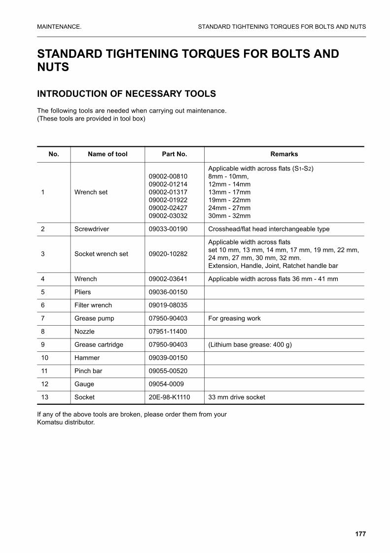
MAINTENANCE. STANDARD TIGHTENING TORQUES FOR BOLTS AND NUTS
STANDARD TIGHTENING TORQUES FOR BOLTS AND NUTS
INTRODUCTION OF NECESSARY TOOLSThe following tools are needed when carrying out maintenance.(These tools are provided in tool box)
If any of the above tools are broken, please order them from yourKomatsu distributor.
No. Name of tool Part No. Remarks
1 Wrench set
09002-0081009002-0121409002-0131709002-0192209002-0242709002-03032
Applicable width across flats (S1-S2)8mm - 10mm, 12mm - 14mm13mm - 17mm19mm - 22mm24mm - 27mm30mm - 32mm
2 Screwdriver 09033-00190 Crosshead/flat head interchangeable type
3 Socket wrench set 09020-10282
Applicable width across flatsset 10 mm, 13 mm, 14 mm, 17 mm, 19 mm, 22 mm,24 mm, 27 mm, 30 mm, 32 mm.Extension, Handle, Joint, Ratchet handle bar
4 Wrench 09002-03641 Applicable width across flats 36 mm - 41 mm
5 Pliers 09036-00150
6 Filter wrench 09019-08035
7 Grease pump 07950-90403 For greasing work
8 Nozzle 07951-11400
9 Grease cartridge 07950-90403 (Lithium base grease: 400 g)
10 Hammer 09039-00150
11 Pinch bar 09055-00520
12 Gauge 09054-0009
13 Socket 20E-98-K1110 33 mm drive socket
177

STANDARD TIGHTENING TORQUES FOR BOLTS AND NUTS MAINTENANCE.
TORQUE LISTUnless otherwise specified, tighten the metric bolts and nuts tothe torque shown in the table.
The tightening torque is determined by the width across the flats(B) of the nut and bolt.
If it is necessary to replace any nut or bolt, always use a Komatsugenuine part of the same size as the part that was replaced.
NOTICEWhen tightening panels or other parts having tightening
fixtures made of plastic, be careful not to use excessivetightening torque: doing so will damage the plastic parts.
Thread diameter of bolt (mm)
(a)
Width across flats (mm)
(b)
N•m kgf•m
68101214
1013171922
13.2 ± 1.431.4 ± 2.965.7 ± 6.8112 ± 9.8177 ± 19
1.35 ± 0.153.2 ± 0.36.7 ± 0.711.5 ± 1.018.0 ± 2.0
1618202224
2427303236
279 ± 29383 ± 39549 ± 58745 ± 78927 ± 98
28.5 ± 339 ± 356 ± 676 ± 894.5 ± 10
2730333639
4146505560
1320 ± 1401720 ± 1902210 ± 2402750 ± 2903280 ± 340
135 ± 15175 ± 20225 ± 25280 ± 30335 ± 35
178

MAINTENANCE. PERIODIC REPLACEMENT OF SAFETY CRITICAL PARTS
PERIODIC REPLACEMENT OF SAFETY CRITICAL PARTS
To ensure safety at all times when operating or driving themachine, the user of the machine must always carry out periodicmaintenance. In addition, to further improve safety, the usershould also carry out periodic replacement of the parts given inthe table. These parts are particularly closely connected to safetyand fire prevention.
With these parts, the material changes as time passed, or theyeasily wear or deteriorate. However, it is difficult to judge the con-dition of the parts simply by periodic maintenance, so they shouldalways be replaced after a fixed time has passed, regardless oftheir condition. This is necessary to ensure that they always main-tain their function completely.
However, if these parts show any abnormality before the replace-ment interval has passed, they should be repaired or replacedimmediately.
If the hose clamps show any deterioration, such as deformation orcracking, replace the clamps at the same as the hoses.
When replacing the hoses, always replace the O-rings, gaskets,and other such parts at the same time.
Ask your Komatsu distributor to replace the safety critical parts.
179

PERIODIC REPLACEMENT OF SAFETY CRITICAL PARTS MAINTENANCE.
SAFETY CRITICAL PARTS
No. Safety critical parts for periodic replacement Q’ty Replacement interval
1 Fuel hose (fuel tank - water separator) 1
Every 2 years or 4000 hours which ever comes sooner.
2 Fuel hose (water separator - engine lift pump 1
3 Fuel hose (engine lift pump - fuel filter) 1
4 Fuel hose (fuel filter - injection pump) 1
5 Spill hose (engine - fuel tank) 1
6 Hydraulic hose (main pump delivery) 1
180

MAINTENANCE. MAINTENANCE SCHEDULE CHART
MAINTENANCE SCHEDULE CHART
SERVICE ITEM PAGE
INITIAL 250 HOURS SERVICE (only after the first 250 hours)
"REPLACE FUEL FILTER CARTRIDGE" page 187
"CHECK ENGINE VALVE CLEARANCE, ADJUST" page 187
"CHANGE OIL IN TRANSMISSION, HUBS + AXLES." page 187
WHEN REQUIRED
"CHECK, CLEAN AND REPLACE THE AIR CLEANER ELEMENT" page 188
"CLEAN INSIDE OF COOLING SYSTEM" page 189
"CHECKING COOLANT LEVEL" page 192
"CHECK AND TIGHTEN WHEEL NUTS" page 195
"CHECK ELECTRICAL INTAKE AIR HEATER" page 195
"CHECK ALTERNATOR" page 195
"CHECK START MOTOR" page 196
"REPLACE BUCKET SIDE CUTTERS" page 196
"REPLACE BUCKET TEETH" page 197
"ADJUST BUCKET CLEARANCE" page 197
"CHECK WINDOW WASHER FLUID LEVEL, ADD FLUID" page 198
"CHECK AND ADJUST AIR CONDITIONER" page 198
"DRAIN ENGINE BREATHER OIL CATCHER" page 199
CHECK BEFORE STARTING
"CHECK COOLANT LEVEL, ADD WATER" page 200
"CHECK OIL LEVEL IN ENGINE OIL PAN, ADD OIL" page 200
"CHECK FUEL LEVEL, ADD FUEL" page 201
"CHECK OIL LEVEL IN HYDRAULIC TANK, ADD OIL" page 202
"CHECK AIR CLEANER FOR CLOGGING" page 202
"CHECK ELECTRIC WIRING" page 203
"CHECK FOR WATER AND SEDIMENT IN SEDIMENTOR. DRAIN WATER AND SEDIMENT" page 203
EVERY 50 HOURS SERVICE
"DRAIN WATER AND SEDIMENT FROM FUEL TANK" page 204
EVERY 100 HOURS SERVICE
"LUBRICATING"
181

MAINTENANCE SCHEDULE CHART MAINTENANCE.
� "Boom cylinder foot pin (2 points)" page 205
� "Boom foot pin (2 points)" page 205
� "Boom cylinder rod end (2 points)" page 205
� "Arm cylinder foot pin (1 point)." page 205
� "Boom-Arm coupling pin (1point)" page 205
� "Arm cylinder rod end (1 point)" page 205
� "Bucket cylinder foot pin (1 point)" page 206
� "Arm-Link coupling pin (1 point)" page 206
� "Arm-Bucket coupling pin (1 point)" page 206
� "Link coupling pin (1 point)" page 206
� "Bucket cylinder rod end (1 point)" page 206
� "Bucket-Link coupling pin (2 points)" page 206
� "Outrigger cylinder foot pin (2 or 4 points)" page 206
� "Outrigger cylinder rod end (2 or 4 points)" page 206
� "Outrigger leg pivot (2 or 4 points)" page 206
� "Outrigger foot pivot (2 or 4 points)" page 206
� "Propshaft." page 206
� "Boom adjust cylinder foot pin (1 point)" page 207
� "Boom adjust cylinder rod end (1 point)" page 207
� "Dozer blade cylinder rod end (2 points)" page 207
� "Dozer blade pivot pin (2 points)" page 207
� "Dozer blade cylinder foot pin (2 points)" page 207
� "Axle pivot (1 point)" page 207
� "Hub pivot (4 points)" page 207
� "Steer links (4 points)" page 207
� "Parallel link pivot pin (2 points)" page 207
� "Dozer blade cylinder rod end (2 points)" page 207
� "Single link pivot pin (2 points)" page 207
� "Dozer blade pivot pins (6 points)." page 207
"CHECK OIL LEVEL IN SWING MACHINERY CASE, ADD OIL" page 208
"CLEAN FRESH AIR INTAKE FILTER" page 208
EVERY 250 HOURS SERVICE
"CHECK OIL LEVEL IN WHEEL HUBS, ADD OIL" page 209
"CHECK OIL LEVEL IN AXLES, ADD OIL" page 210
SERVICE ITEM PAGE
182

MAINTENANCE. MAINTENANCE SCHEDULE CHART
"CHECK OIL LEVEL IN TRANSMISSION, ADD OIL" page 210
"CHECK LEVEL OF BATTERY ELECTROLYTE" page 211
"LUBRICATE SWING CIRCLE (2 points)" page 211
"BELTS, GENERAL" page 211
"CHECK FAN BELT TENSION, ADJUST CHECKING TENSION" page 212
"CHECK ALTERNATOR AND WATER PUMP BELT TENSION, ADJUST CHECKING TENSION" page 213
"CHECK AND ADJUST TENSION OF AIR CONDITIONER COMPRESSOR BELT" page 214
EVERY 500 HOURS SERVICE
"REPLACE FUEL FILTER CARTRIDGES" page 215
"CHECK SWING PINION GREASE LEVEL, ADD GREASE" page 217
"CHANGE OIL IN ENGINE OIL PAN, REPLACE ENGINE OIL FILTER CARTRIDGE" page 218
"CLEAN AND INSPECT RADIATOR FINS, OIL COOLER FINS AND CONDENSER FINS (ONLY FOR MACHINES EQUIPPED WITH AIR-CONDITIONER)" page 219
"REPLACE HYDRAULIC TANK BREATHER ELEMENT" page 220
"REPLACE HYDRAULIC FILTER ELEMENT" page 220
EVERY 1000 HOURS SERVICE
"CHANGE OIL IN SWING MACHINERY CASE" page 221
"CHECK ALL TIGHTENING PARTS OF TURBOCHARGER" page 222
"CHECK PLAY OF TURBOCHARGER ROTOR." page 222
"CHECK & ADJUST VALVE CLEARANCE" page 222
"CHECK FAN BELT TENSIONER BEARING BELT AND FAN HUB" page 224
"CHECK FAN BELT TENSION" page 224
EVERY 2000 HOURS SERVICE
"CLEAN HYDRAULIC TANK STRAINER" page 225
"CLEAN, CHECK TURBOCHARGER" page 225
"CHECK ALTERNATOR, STARTING MOTOR" page 225
"CHECK VIBRATION DAMPER" page 226
"CHANGE OIL IN AXLES" page 226
"CHANGE OIL IN HUBS" page 227
"CHANGE OIL IN TRANSMISSION ASSEMBLY" page 227
"CHANGE ANTIFREEZE" page 227
"CHECK AND ADJUST VALVE CLEARANCE" page 227
EVERY 4000 HOURS SERVICE
"CHECK WATER PUMP" page 228
SERVICE ITEM PAGE
183

MAINTENANCE SCHEDULE CHART MAINTENANCE.
KEY TO LUBRICATION POINTS
EVERY 5000 HOURS SERVICE
"CHANGE OIL IN HYDRAULIC TANK" page 228
SERVICE ITEM PAGE
1. Engine oil check level change oil 23. Rear propshaft grease
2. Hydraulic oil check level change oil 24. Rear propshaft grease
3. Boom cylinder foot pin grease 25. Dozer blade cylinder foot pin grease
4. Boom foot pin grease 26. Dozer blade cylinder rod end grease
5. Boom cylinder rod end grease 27. Dozer blade pivot pin grease
6. Arm cylinder foot pin grease 28. Outrigger foot pivot grease
7. Boom arm coupling pin grease 29. Outrigger cylinder rod end grease
8. Arm cylinder rod end grease 30. Outrigger leg pivot grease
9. Bucket cylinder foot pin grease 31. Outrigger cylinder foot pin grease
10. Bucket cylinder rod end grease 32. Transmission oil check level change oil
11. Bucket-link coupling pin grease 33. Wheel hubs (front) check level change oil
12. Arm-bucket coupling pin grease 34. Wheel hubs (rear) check level change oil
13. Arm-link coupling pin grease 35. Front axle check level change oil
14. Link coupling pin grease 36. Rear axle check level change oil
15. Swing machinery oil check level change oil 37. Hydraulic filter element change filter
16. Adjust cylinder rod end grease 39. Swing pinion grease
17. Adjust cylinder foot pin grease 40. Swing circle grease
18. 1st boom - 2nd boom coupling pin grease 41. Engine oil filter change filter
19. Hub pivot grease 42. Fuel filters change filter
20. Steer links grease
21. Axle pivot grease
184

MAINTENANCE. MAINTENANCE SCHEDULE CHART
Interval of service Change filter
Lubrication by greasing (G) Amount of oil required at change (liters)
Check oil level/change (EO)
185

MAINTENANCE SCHEDULE CHART MAINTENANCE.
MAINTENANCE WHEN USING HYDRAULIC BREAKERFor machines equipped with a hydraulic breaker, the hydraulic oildeteriorates faster than for normal bucket digging operations, soset the maintenance intervals as follows.
� Replacing hydraulic filter elementOn new machines, replace the element after the first 100 to150 hours, then carry out further replacement of the elementaccording to the table on the right.
� Changing oil in hydraulic tankChange the oil according to the table on the right.
AD31373D
Replacement intervalfor hydraulic oil
Breaker operation (ratio %)Hydraulic
Fillerelement
Rep
lace
men
t int
erva
l (H
)
(When using breaker only
(When notusing breaker)
186

MAINTENANCE. SERVICE PROCEDURE
SERVICE PROCEDURE
INITIAL 250 HOURS SERVICE
Carry out the following maintenance only after the first 250 hours.
� REPLACE FUEL FILTER CARTRIDGE
see “REPLACE FUEL FILTER CARTRIDGES” onpage 215.
� CHECK ENGINE VALVE CLEARANCE, ADJUST
see “CHECK & ADJUST VALVE CLEARANCE” onpage 222.
For details of the method of replacing or maintaining, seethe section on EVERY 500 HOURS and 2000 HOURS SER-VICE.
� CHANGE OIL IN TRANSMISSION, HUBS + AXLES.
187

SERVICE PROCEDURE MAINTENANCE.
WHEN REQUIRED
CHECK, CLEAN AND REPLACE THE AIR CLEANER ELEMENT
WARNING
� Never clean or replace the air cleaner element with theengine running.
� When using pressured air to clean the element, wearsafety glasses or goggles to protect the eyes.
Checking
If air cleaner clogging monitor flashes, clean the air cleaner ele-ment.
Cleaning or replacing the outer element
1. Open the machine door, loosen wing nut (2), then removecover (6).Remove wing nut, then take out element (7).
2. To prevent dirt or dust from entering, use tape or a clean clothto cover the inner element of the air cleaner body.
3. Clean the air cleaner body interior and the cover.
4. Direct dry compressed air (less than 700 kPa (7 kg/cm²)) toelement (7) from inside along its folds, then direct it from out-side along its folds and again from inside.
❍ Remove one seal from the outer element whenever theouter element has been cleaned.
❍ Replace the outer element which has been cleaned 6times repeatedly or used throughout a year. Replace theinner element at the same time.
❍ Replace both inner and outer elements when the monitorlamp (3) flashes soon after installing the cleaned outerelement (even if it has not been cleaned 6 times).
AD313740A
7
188

MAINTENANCE. SERVICE PROCEDURE
❍ Check inner element mounting nuts for looseness and, ifnecessary, retighten.
5. If small holes or thinner parts are found on the element whenit is checked by shining a light through it after cleaning,replace the element.
NOTICEDo not use an element whose folds or gasket or seal are
damaged. When cleaning the element, do not hit it or beat itagainst anything. Wrap up unused elements and store themin a dry area.
6. Remove the cloth and tape used for cover in Step 1.
7. Install the cleaned element and fix it with the wing nut.
8. If seal washer (4) is damaged or the thread of wing nut (2) isbroken, replace it with a new part.
9. Remove vacuator valve (5) and clean with compressed air.After cleaning, install again.
Replacing the inner element
1. Firsts remove the cover and the outer element, and thenremove the inner element.
2. To prevent dust from getting in, use a clean cloth or tape tocover the air connector (outlet side).
3. Clean the air cleaner body interior, then remove the coverinstalled in Step 2.
4. Fit a new inner element to the connector and tighten it withthe nuts. Do not clean and reinstall a inner element.
5. Install the outer element and fix it with the wing nut.
CLEAN INSIDE OF COOLING SYSTEM
WARNING
� Soon after the engine has been stopped, the coolant ishot and can cause personal injury. Allow the engine tocool before draining water.
� Since cleaning is performed while the engine is running,it is very dangerous to enter the rear side of the machineas the machine may suddenly start moving. If the undercover is left removed, it may interfere with the fan. Whilethe engine is running, never enter the rearside of the ma-chine.
� Never remove the radiator cap when the engine is atoperating temperature. At operating temperature, thecoolant is under pressure. Steam blowing up from theradiator could cause personal injury. Allow the engine to
189

SERVICE PROCEDURE MAINTENANCE.
cool until the radiator filler cap is cool enough to touchwith your hand. Remove the filler cap slowly to allowpressure to be relieved.
GENERAL
The cooling system operates under pressure which is controlledby the pressure relief valve in the radiator cap.
The belt-driven water pump circulates the coolant through theengine block, cylinder heads, radiator and engine oil cooler. Cir-culation is controlled by the thermostat which by-passes coolantflow around the radiator until the engine reaches operating tem-perature.
Proper cooling is possible only when the system is sealed, theradiator cap gasket is in good condition, the pressure relief valveand thermostat are operating properly. The system is free of cool-ant and air flow restrictions and the system is filled to the properlevel.
Selection and maintenance of the engine coolant is important tolong engine life. The following information provides recommenda-tions for selecting the engine coolant, maintaining the coolantinhibitors and servicing the cooling system.
The system operates successfully with a water/antifreeze mixtureor inhibited/conditioned water as the coolant. Water alone allowsrust, scale deposits, and corrosion to occur within the system.
Every 2000 hours, the cooling system should be drained, flushed,and refilled as described in this section.
When deciding the ratio of antifreeze to water, check the lowest;temperature in the past, and decide from the mixing rate tablegiven below.
It is actually better to estimate a temperature about 10°C lowerwhen deciding the mixing rate.
Mixing rate of water and antifreeze
Min. atmospherictemperature
º C -5 -10 -15 -20 -25 -30
Amount ofantifreeze liters 4.6 6 7.2 8.2 9.2 9.95
Amount ofwater liters 15.4 14 12.8 11.8 10.8 10.05
190

MAINTENANCE. SERVICE PROCEDURE
WARNING
Antifreeze is flammable, so keep it away from any flame.
� Use city water for the cooling water.If river water, well water or other such water supply must beused, contact your Komatsu distributor.
� We recommend use of an antifreeze density gauge to controlthe mixing proportions.
WARNING
When removing drain plug, avoid pouring coolant on your-self.
REMOVAL
WARNING
� Hot, scalding coolant can spray out if the radiator cap isremoved suddenly. Relieve system pressure by slowlyturning the cap to the first notch or lifting the safety lever(if equipped). Remove the cap only after the pressure isrelirved.
� Use extreme caution when adding coolant to the radiatorto avoid being burned. Wear gloves and goggles andkeep face away from the filler neck.
To remove the cap, turn the cap to the left, or counterclockwise upto the safety stop until the cap is free to be removed.
INSTALLATION
When installing the cap, the gasket and contacting surfaces mustbe clean. Turn the cap to the right, or clockwise until snug.
191

SERVICE PROCEDURE MAINTENANCE.
CHECKING COOLANT LEVEL
REMARKCheck the coolant level before starting the engine.
1. Check the coolant level in the radiator reserve tank (5). Thecoolant level should be between the FULL and LOW mark-ings on the tank.
2. If coolant must be added, remove the reserve tank cap (4)and add coolant until level is between the FULL and LOWmarkings on the tank.
DRAINING THE SYSTEM
WARNING
� Before working on the engine or electrical system, dis-connect the negative (ground) battery cable. Tag thecable and controls to warn against starting.
� Wear hand and eye protection when draining hot fluids.
1. Run the engine until it reaches operating temperature; thenstop the engine
2. Remove the radiator cap as outlined in this section.
3. Remove the crankcase coolant drain plug located on the bot-tom of the coolant inlet (1).
4. Open the radiator drain valve (2).
5. Allow the system to completely drain into a suitable container.Do not let drain outlets plug up during draining.
6. Close the radiator drain valve (2). Install the crankcase cool-ant drain plug (1).
CLEANING THE SYSTEM
At 2000 hours clean the cooling system as follows:
1. Drain the system into a suitable container. Refer to “DRAIN-ING THE SYSTEM” on page 192.
2. Drain and clean the reserve tank.
3. Close the radiator and crankcase drains.
Full
Low
192

MAINTENANCE. SERVICE PROCEDURE
4. Fill the system with clean water, refer to “FILLING THE SYS-TEM” on page 193 and add a flushing compound that is com-patible with aluminium. Flush the system in accordance withthe instructions furnished with the compound.
5. After flushing, rinsing and completely draining the system.Refill with clean coolant. Refer to“FILLING THE SYSTEM” onpage 193.
FILLING THE SYSTEM
REMARKBe sure to fill the heater and heater supply lines with fresh
coolant, even if the heater is not in use (warm weather). Leavingthe heater core empty causes corrosion in the heater.
1. Be sure the radiator drain valve and crankcase drain plugsare closed and tightened.
2. Fill the cooling system to maximum capacity. Fill with anti-freeze.
3. Open the after-cooler air drain valve (4) and add coolant untilit overflows from the water filler. When the coolant comes upto near the water filler port, close the air drain valve.For cool-ant specifications, see COOLANT SYSTEM”.
4. Start engine and run until normal operating temperature isreached. Add coolant when needed to keep proper level inreserve tank.
5. After all air is removed and level remains fixed, install theradiator cap.
6. Fill the radiator reserve tank with coolant until level isbetween the FULL and LOW markings on the tank.
REFILLING AN OVERHEATED SYSTEM
Do not add coolant to the radiator of an overheated engine unlessabsolutely necessary. However, if necessary:
1. Remove the radiator cap. Refer to “RADIATOR CAP” in thissection.
2. Be sure all the drains are closed.
WARNING
Use extreme caution when adding coolant to a hot radiator toavoid being burned. Wear gloves and goggles and keep awayfrom the filler neck.
3. Add coolant to the radiator slowly until full.
4. Remove the reserve tank cap.
193

SERVICE PROCEDURE MAINTENANCE.
5. Add coolant to the reserve tank until the level is betweenFULL and LOW marking on the tank.
6. When coolant level remains fixed between the FULL andLOW on the reserve tank, install the reserve tank cap.
7. Run the engine
8. Stop the engine
9. Check for leaks and coolant level in the reserve tank.
CLEANING THE RADIATOR
Minor internal sludge accumulations will be removed when flush-ing the cooling system.
When internal accumulations are found that cannot be removedby normal flushing methods, consult your distributor.
Remove all bugs and dirt from the radiator core, using air or waterunder pressure. Direct the flow through the core, opposite to thenormal direction of air flow.
CLEANING THE RADIATOR PRE-SCREEN
1. Remove the bolts retaining the radiator pre-screen andremove the pre-screen.
2. Clean the pre-screen with water under pressure.
3. Reinstall the pre-screen and retaining bolts.
THERMOSTATS
REMOVAL
1. Drain the cooling system. Refer to “DRAINING THE SYS-TEM” on page 192 in this section.
2. Remove the components and housing to access the thermo-stats.
3. Remove the thermostats and clean all gasket material fromeither mating surfaces.
INSTALLATION
1. Install two new thermostats with new gasket.
2. Re-install thermostat housing and all component parts.
3. Fill the cooling system. Refer to “COOLING THE SYSTEM” inthis section.
194

MAINTENANCE. SERVICE PROCEDURE
FAN
WARNING
Personal injury can result from a fan blade failure. Never pullor pry on the fan. This can damage the fan blade(s) andcause fan failure.
Check the fan for cracks, loose rivets (for metal fans) and bent orloose blades. Make sure it is securely mounted. Tighten the cap-screws if loose. Replace damaged fans.
CHECK AND TIGHTEN WHEEL NUTS
Order for tightening
Tighten the bolts in the order shown in the diagram. Torque to 450Nm.
CHECK ELECTRICAL INTAKE AIR HEATER
Before the start of the cold season (once a year), contact yourKomatsu distributor to have the electrical intake air heaterrepaired or checked for dirt or disconnections.
CHECK ALTERNATOR
GENERAL
The alternator requires no lubrication since its bearings are fac-tory lubricated for life and require attention only at the time ofmajor overhaul.
The alternator is equipped with an integral, transistorized voltageregulator. If the alternator fails to operate properly, consult yourdistributor.
PRECAUTIONS
NOTE: The unit electrical system is negative ground. Be CER-TAIN the ground polarity is correct when:
195

SERVICE PROCEDURE MAINTENANCE.
a. Installing a new battery.
b. Connecting a battery charger.
c. Using a booster.
Failure to observe proper polarity will result in damage to thealternator.
NEVER use a fast charger as a booster to start the engine.
NEVER unhook a battery terminal while the engine is running.
NEVER disconnect the alternator cable while the engine is run-ning.
NOTE: Do not short across or ground any terminals of the alter-nator. Do not connect any cable to the “R” terminal on thealternator. This will result in severe damage to the har-ness and radiator.
CHECK START MOTOR
Under normal operating conditions, no maintenance is requiredbetween engine overhaul periods. At the time of engine overhaul,the motor should be disassembled, inspected, cleaned andtested. Contact your distributor for detailed information.
REPLACE BUCKET SIDE CUTTERS
WARNING
It is dangerous if the work equipment moves by mistakewhen the teeth are being replaced. Set the work equipment ina stable condition, then stop the engine and apply the con-trol lever pad safety lock.
1. Untighten nuts (5) and bolts (3) and remove side cutters (1)and (2).
2. Clean cutter mounting face on bucket side plate.
3. Check nuts and bolts and replace if damaged.
4. Fit new side cutters.
5. Tighten bolts to 110 ± 10 kgm.
NOTE: When side cutters are not being used shrouds (6) shouldbe fitted to prevent wear of the bucket side plate.
196

MAINTENANCE. SERVICE PROCEDURE
REPLACE BUCKET TEETH
Replace the teeth before the wear reaches the adaptor.
WARNING
It is dangerous if the work equipment moves by mistakewhen the teeth are being replaced. Set the work equipment ina stable condition, then stop the engine and apply the con-trol lever pad safety lock.
NOTICEPlease confirm with your bucket supplier for the correct pro-cedure to replace bucket teeth and side cutters.
ADJUST BUCKET CLEARANCE
WARNING
It is dangerous if the work equipment moves by mistakewhen the clearance is being adjusted.Set the work equipment in a stable condition, then stop theengine and lock control lever pad safety lock.
1. Set the work equipment to the position shown in the diagramat right, stop the engine and set the safety lock lever to thelock position.
2. Shift 0-ring (1) of the linkage and measure the amount of play(a). Measurement is easier if you move the bucket to one sideor the other so all the play can be measured in one place.(In the diagram this is on the left-hand side)Use a gap (clearance) gauge for easy and accurate measure-ment.
197

SERVICE PROCEDURE MAINTENANCE.
3. Loosen the four plate fixing bolts of (2) and loosen plate (3).Because it uses split shims, you can carry out the operationwithout removing the bolts entirely.
4. Remove shim (4) corresponding to the amount of play (a)measured above.
[Example]If the play is 3 mm, remove two sets of 1.0 mm shim (4 pieces)and 0.5 mm (2 pieces) and the play will become 0.5 mm.Four sets of 1.0 mm (8 pieces), two sets of 0.5 mm (4 pieces) areinstalled. Two pieces of shim makes one set.
When play (a) is smaller than one shim, do not carry out anymaintenance.
5. Tighten the four bolts (2).If the bolts (2) are too stiff to tighten, pull out pin stopper bolt(5) for easier tightening.
CHECK WINDOW WASHER FLUID LEVEL, ADD FLUID
If air is ejected with the window washer fluid, check the fluid levelin window washer tank (1). If showing under the level, fill withautomobile window washer fluid.
When adding fluid, be careful not to let dirt or dust get in.
� Mixture ratio of pure washer fluid and waterSince the ratio should be varied depending on atmospherictemperature, replenish washer fluid at the following mixtureratio, taking temperature into account.
Pure washer fluid comes in two types: for -10°C (for general use)and for -30°C (cold regions).Use pure washer fluid according to operation area and season.
CHECK AND ADJUST AIR CONDITIONER
CHECK LEVEL OF REFRIGERANT (GAS)
WARNING
If the liquid get into your eyes or on your hands, it may causeloss of sight or frostbite, so never loosen any part of therefrigerant circuit.
The air conditioning system is equipped with pressure switches
Operation area and season Mixture ratio Freezing temperature
Normal Pure washer 1/3: water 2/3 fluid - 10° C
Winter in cold region Pure washer fluid 1/2: water 1/2 - 20°C
Winter in extremely cold region Pure washer fluid - 30°C
198

MAINTENANCE. SERVICE PROCEDURE
which disable the system if the pressure is too high or low, to pre-vent damage to the system.
If the air conditioner fails to operate it may be due to:
a) Low pressure
i) Check for leaks.ii) Consult your distributor to recharge system.
b) High pressure
i) Check for blockages in piping.
Check in off-season
When not being used for a long period, operate the cooler for 3 to5 minutes once a month to supply lubricant to each component ofthe compressor.
Inspection and maintenance items list for cooler
DRAIN ENGINE BREATHER OIL CATCHER
Periodically drain oil from the engine breather catcher and when-ever it is necessary to remove the engine undercover.
1. Remove plug (1) from engine undercover (3) and allow oil todrain out.
2. Replace plug (1).
Ensure that the breather hose (2) is positioned onto catcher res-ervoir whenever the undercover is removed.
Inspection and maintenance items Contents Maintenance interval
Refrigerant (gas) Filling quantity Twice a year; spring and autumn
Condenser Clogging of fin Every 500 hours
Compressor Function Every 4000 hours
V belt Damage and tension Every 250 hours
Blower motor and fan Function (Check for normal sound) When required
Control mechanism Function (Check for function) When required
Piping for connection Installation condition looseness of tightening connection portion gas leakage, damage
When required
199

SERVICE PROCEDURE MAINTENANCE.
CHECK BEFORE STARTING
CHECK COOLANT LEVEL, ADD WATER
WARNING
Do not open the radiator cap unless necessary. When check-ing the coolant, always check the radiator reserve tank whenthe engine is cold.
1. Open the rear door on the left side of the machine and checkthat the cooling water level is between the FULL and LOWmarks on radiator reserve tank (1) (shown in the diagram onthe right).If the water level is low, add water through the water filler ofreserve tank (1) to the FULL level.
2. After adding water, tighten the cap securely.
3. If the reserve becomes empty, first inspect for water leaksand then fill the radiator and the reserve tank with water.
CHECK OIL LEVEL IN ENGINE OIL PAN, ADD OIL
1. Open the engine hood.
2. Remove dipstick (G) and wipe the oil off with a cloth.
3. Insert dipstick (G) fully in the oil gauge pipe, then take it outagain.
4. The oil level should be between the H and L marks on dipstick(G). If the oil level is below the L mark, add engine oil throughoil filler (F).
For details of the oil to use, “USE FUEL, COOLANT ANDLUBRICANTS ACCORDING TO AMBIENT TEMPERA-TURE” on page 173
5. If the oil is above the H mark, drain the excess engine oil fromdrain valve (P), and check the oil level again.
6. If the oil level is correct, tighten the oil filler cap securely andclose the engine hood.
REMARKEnsure that the machine is level when checking oil level.
AM090180
AD052340A
200

MAINTENANCE. SERVICE PROCEDURE
WARNING
Allow the engine to cool before checking the oil level toavoid burns by touching hot engine parts.
CHECK FUEL LEVEL, ADD FUEL
WARNING
When adding fuel, never let the fuel overflow. This may causea fire. If spilling fuel, thoroughly clean up any spillage.
1. Use sight gauge (G) on the front face of the fuel tank to checkthat the tank is full.
2. If the fuel level is not within the sight gauge, add fuel throughfiller port (F) while watching sight gauge (G).
Fuel capacity: 240 l
For details of the fuel to use, see “USE FUEL, COOLANTAND LUBRICANTS ACCORDING TO AMBIENT TEMPER-ATURE” on page 173.
3. After adding fuel, tighten the cap securely.
REMARKIf breather hole (1) on the cap is clogged, the pressure in the
tank will drop and fuel will not flow.Clean the hole from time to time.
201

SERVICE PROCEDURE MAINTENANCE.
CHECK OIL LEVEL IN HYDRAULIC TANK, ADD OIL
WARNING
� When removing the oil filler cap, oil may spurt out, soturn the cap slowly to release the internal pressurebefore removing the cap.
� If oil has been added to above the H mark, stop theengine and wait for the hydraulic oil to cool down, thendrain the excess oil from drain plug (P).
1. If the work equipment is not in the condition shown in the dia-gram on the right, start the engine run the engine at lowspeed, retract the arm and bucket cylinders, then lower theboom, set the bucket teeth in contact with the ground, andstop the engine.
2. Check sight gauge (G). The oil level is normal if between theH and L marks.
NOTE: Do not add oil if the level is above the H line. This willdamage the hydraulic equipment and cause the oil tospurt out.
3. If the level is below the L mark, remove cap (F) from thehydraulic tank and add oil.
For details of the oil to use, see “USE FUEL, COOLANTAND LUBRICANTS ACCORDING TO AMBIENT TEMPER-ATURE” on page 173.
REMARKThe oil level will vary depending upon the oil temperature.
Accordingly, use the following as a guide:
� Before operation: around L level(Oil temperature 10 to 30°C)
� Normal operation: around H level(Oil temperature 50 to 80°C).
CHECK AIR CLEANER FOR CLOGGING
1. Confirm that the air cleaner clogging monitor does not flash(1).
2. If it flashes, immediately clean or replace the element.
For details of the method of cleaning the element, see“CHECK, CLEAN AND REPLACE THE AIR CLEANERELEMENT” on page 188. AD313590A
1
202

MAINTENANCE. SERVICE PROCEDURE
CHECK ELECTRIC WIRING
WARNING
If the fuse blows frequently, or there are traces of short-cir-cuiting in the electric wiring, always locate and repair thecause.
Check for damage of the fuse and any sign of disconnection orshort circuit in the electric wiring. Check also for loose terminalsand tighten any loose parts. Check the following points carefully.
� Battery
� Starting motor
� Alternator
Please contact your Komatsu distributor for investigation and cor-rection of the cause.
CHECK FOR WATER AND SEDIMENT IN SEDIMEN-TOR. DRAIN WATER AND SEDIMENT
A fuel sedimentor is mount in the radiator compartment and isaccessed by the door on the left hand side of the machine.Entrapped sediment and water can be seen through the glassbow.
1. Loosen drain plug (1) and drain water and sediment untilnone is visible in bowl.
2. Tighten drain plug.
CHECK FOR WATER IN PRIMARY FUEL FILTER, DRAIN WATER
A primary fuel filter is fitted in the pump compartment. Drain thewater from the primary fuel filter by turning cap at the bottom ofthe filter.
(A): Fuel
(B): Water/sediment
203

SERVICE PROCEDURE MAINTENANCE.
EVERY 50 HOURS
DRAIN WATER AND SEDIMENT FROM FUEL TANK
1. Carry out this procedure before operating the machine.
2. Prepare a container to catch the fuel that is drained.
3. Open valve (1) at the bottom of the tank and drain the sedi-ment and water that has accumulated at the bottom togetherwith fuel. When doing this, be careful not to get fuel on your-self.
4. When only clean fuel comes out, close drain valve (1).
NOTE: Never use trichlene for washing the inside of the tank.
EVERY 100 HOURS SERVICE
Maintenance every 50 hours should be carried out at the same time.
LUBRICATING
The minimum greasing interval is 100 hours, however more fre-quent greasing will be required depending on conditions/environ-ment.
1. Set the work equipment in the greasing posture below, thenlower the work equipment to the ground and stop the engine.
2. Using a grease pump, pump in grease through the grease fit-tings shown by arrows.
204
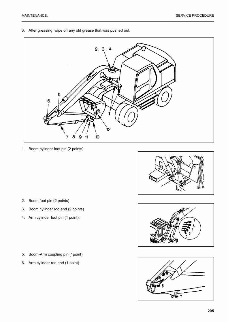
MAINTENANCE. SERVICE PROCEDURE
3. After greasing, wipe off any old grease that was pushed out.
1. Boom cylinder foot pin (2 points)
2. Boom foot pin (2 points)
3. Boom cylinder rod end (2 points)
4. Arm cylinder foot pin (1 point).
5. Boom-Arm coupling pin (1point)
6. Arm cylinder rod end (1 point)
205

SERVICE PROCEDURE MAINTENANCE.
7. Bucket cylinder foot pin (1 point)
8. Arm-Link coupling pin (1 point)
9. Arm-Bucket coupling pin (1 point)
10. Link coupling pin (1 point)
11. Bucket cylinder rod end (1 point)
12. Bucket-Link coupling pin (2 points)
13. Outrigger cylinder foot pin (2 or 4 points)
14. Outrigger cylinder rod end (2 or 4 points)
15. Outrigger leg pivot (2 or 4 points)
16. Outrigger foot pivot (2 or 4 points)
17. Propshaft.
206
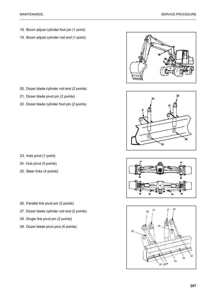
MAINTENANCE. SERVICE PROCEDURE
18. Boom adjust cylinder foot pin (1 point)
19. Boom adjust cylinder rod end (1 point)
20. Dozer blade cylinder rod end (2 points)
21. Dozer blade pivot pin (2 points)
22. Dozer blade cylinder foot pin (2 points)
23. Axle pivot (1 point)
24. Hub pivot (4 points)
25. Steer links (4 points)
26. Parallel link pivot pin (2 points)
27. Dozer blade cylinder rod end (2 points)
28. Single link pivot pin (2 points)
29. Dozer blade pivot pins (6 points).
207
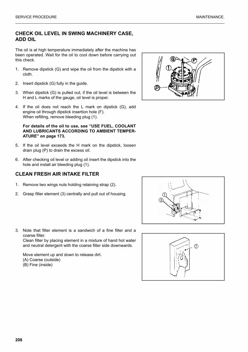
SERVICE PROCEDURE MAINTENANCE.
CHECK OIL LEVEL IN SWING MACHINERY CASE, ADD OIL
The oil is at high temperature immediately after the machine hasbeen operated. Wait for the oil to cool down before carrying outthis check.
1. Remove dipstick (G) and wipe the oil from the dipstick with acloth.
2. Insert dipstick (G) fully in the guide.
3. When dipstick (G) is pulled out, if the oil level is between theH and L marks of the gauge, oil level is proper.
4. If the oil does not reach the L mark on dipstick (G), addengine oil through dipstick insertion hole (F).When refilling, remove bleeding plug (1).
For details of the oil to use, see “USE FUEL, COOLANTAND LUBRICANTS ACCORDING TO AMBIENT TEMPER-ATURE” on page 173.
5. If the oil level exceeds the H mark on the dipstick, loosendrain plug (P) to drain the excess oil.
6. After checking oil level or adding oil insert the dipstick into thehole and install air bleeding plug (1).
CLEAN FRESH AIR INTAKE FILTER
1. Remove two wings nuts holding retaining strap (2).
2. Grasp filter element (3) centrally and pull out of housing.
3. Note that filter element is a sandwich of a fine filter and acoarse filter.Clean filter by placing element in a mixture of hand hot waterand neutral detergent with the coarse filter side downwards.
Move element up and down to release dirt.(A) Coarse (outside)(B) Fine (inside)
208

MAINTENANCE. SERVICE PROCEDURE
Rinse filter with clean water from the fine filter side.
4. Dry filter, compressed air may be used, but apply air from finefilter side.
5. Refit filter element ensuring coarse filter side is facing out-wards.
NOTICEThe normal cleaning interval is 100 hours, however if the
machine is used in a dusty environment, shorten this inter-val.
EVERY 250 HOURS SERVICE
CHECK OIL LEVEL IN WHEEL HUBS, ADD OIL
� Prepare a hexagonal wrench
1. Set so that plug (1) is at the horizontal position.
2. Remove plug.
3. If no oil emerges, turn hub so that hole is at the top and addoil.
4. Turn hub so that hole is horizontal.
5. Repeat steps 3 and 4.
For details of the oil to use see “USE FUEL, COOLANTAND LUBRICANTS ACCORDING TO AMBIENT TEMPER-ATURE” on page 173.
6. After checking, install plug (1).
209

SERVICE PROCEDURE MAINTENANCE.
CHECK OIL LEVEL IN AXLES, ADD OIL
1. Ensure axle is horizontal and remove plug (1).
2. If no oil emerges attach tube and funnel and add oil until oilemerges from the hole after removing tube.
3. Replace plug (1).
For details of the oil to use, see “USE FUEL, COOLANTAND LUBRICANTS ACCORDING TO AMBIENT TEMPER-ATURE” on page 173.
CHECK OIL LEVEL IN TRANSMISSION, ADD OIL
1. Remove level plug (2).
2. If oil emerges replace plug (2)
3. If no oil emerges remove plug (1) and add oil until oil emergesfrom plug hole (2).
4. Replace plugs.
For details of the oil to use, see “USE FUEL, COOLANTAND LUBRICANTS ACCORDING TO AMBIENT TEMPER-ATURE” on page 173.
210

MAINTENANCE. SERVICE PROCEDURE
CHECK LEVEL OF BATTERY ELECTROLYTE
WARNING
� To avoid gas explosions, do not bring fire or sparks nearthe battery.
� Battery electrolyte is dangerous. If it gets in your eyes oron your skin, wash it off with large amounts of water, andconsult a doctor.
Carry out this check before operating the machine.
1. Open the battery door on the left side of the machine.
2. Remove cap (1), and check that the electrolyte is at the spec-ified level (10 to 12 mm above the plate). If the electrolytelevel is low, add distilled water to the specified level.
If the battery electrolyte is spilled, have dilute sulphuric acidadded.
3. Clean the air hole in the battery cap, then tighten the capsecurely.
When adding distilled water in cold weather, add it before startingoperations in the morning to prevent the electrolyte from freezing.
LUBRICATE SWING CIRCLE (2 points)
1. Lower the work equipment to the ground.
2. Using a grease pump, pump in grease through the grease fit-tings shown by arrows.
3. After greasing, wipe off all the old grease that was pushedout.
BELTS, GENERAL
WARNING
Before working on the engine or electrical system, disonnectthe negative (ground) battery cable. Tag the cable and con-trols to warn against starting.
Replace badly worn, greasy or severely cracked belts immedi-ately. These conditions prevent the belt from functioning correctly.
Prior to installing new belts, make sure all pulley grooves areclean and not worn. If a pulley is damaged or if the grooves areworn, it should be replaced.
211

SERVICE PROCEDURE MAINTENANCE.
All pulley support bearings, shafts and brackets must be in work-ing order.
When replacing belts and pulleys, pulley alignment must bechecked with belts tensioned and brackets securely clamped. Amisalignment that can be detected by the naked eye is detrimen-tal to belt performance.
During belt installation, do not force the belts into the pulleygrooves by prying with a screwdriver on pry bar. This will damagethe belt side cords which will cause the belts to turn and result incomplete destruction of the belts in operation.
Belts on new machines and replacement belts lose their tensionas they seat into the pulley grooves. Check the tension of newbelts at 20 hour intervals until tension is stabilized and thereafter,every 250 hours. If the tension falls below the required minimum,the belt slips, and damages the belts and pulley grooves.
REMARKWhen operating in abrasive conditions, check tension every
100 hours.
Visually inspect the belts for intersecting cracks. Transverse(across the belt width) cracks are acceptable. Longitudinal (direc-tion of belt length) cracks that intersect with transverse cracks arenot acceptable. Replace the belt if it is frayed or has pieces ofmaterial missing.
CHECK FAN BELT TENSION, ADJUST CHECKING TENSION
The engine is equipped with an automatic belt tensioner thatmaintains correct tension on the drive belt. To check belt tensiona Gates type gauge must be used because of the wide drive belt.Proper tension should be 355 to 455 N.m gauge value.
If a Gates type gauge is not available, tension may be checked bybelt deflection. Press the belt with your finger at the longest spanand measure the deflection. Maximum deflection 9.5 to 12.7 mm.
212

MAINTENANCE. SERVICE PROCEDURE
ADJUSTING
With the automatic belt tensioner, no adjustment is required.
REPLACEMENT
To replace the drive belt, place a 3/8 in. drive rachet (2) in the 3/8in. square drive hole in the belt tensioner. Push the rachet “UP” toloosen the tensioner. Remove the old belt (1). Inspect belt ten-sioner. The tensioner pulley should spin freely with no roughspots detected under hand pressure. Install the new belt.
CHECK ALTERNATOR AND WATER PUMP BELT TENSION, ADJUST CHECKING TENSION
The engine is equipped with an automatic belt tensioner thatmaintains correct tension on the drive belt. To check belt tensiona “Gates” type gauge must be used because of the wide drivebelt. Proper tension should be 355 to 455 N.m gauge value.
If a “Gates” type gauge is not available, tension may be checkedby belt deflection. Press the belt with your finger at the longestspan and measure the deflection. Maximum deflection 9.5 to 12.7mm.
ADJUSTMENT
With the automatic belt tensioner, no adjustment is required.
REPLACEMENT
To replace the drive belt, place a 3/8 in. drive rachet in the 3/8 in.square drive hole in the belt tensioner. Push the rachet “UP” toloosen the tensioner. Remove the old belt. Inspect belt tensioner.The tensioner pulley should spin freely with no rough spotsdetected under hand pressure. Install the new belt.
NOTE: The belt tensioner is spring loaded and must be pivotedaway from the belt. Pivoting in the wrong direction canresult in damage to the belt tensioner.
213

SERVICE PROCEDURE MAINTENANCE.
CHECK AND ADJUST TENSION OF AIR CONDI-TIONER COMPRESSOR BELT
Testing
The belt should deflect 14-16 mm when pressed with a fingerforce of approx. 6 kg at a point midway between the crankshaftpulley and the compressor pulley.
Adjusting
1. Loosen 2 bolts (1) and 2 bolts (2), and move compressor (3)to adjust.
2. When the deflection is correct, tighten bolts (1) and (2) to holdthe compressor in position.
3. Check each pulley for damage, and check the V-groove andV-belt for wear. In particular, check that the V-belt is not con-tacting the bottom of the V-groove.
4. If the V-belt is streched and cannot be adjusted any further, orif there are any cuts or cracks, replace the V-belt.
5. After replacing the V-belt, adjust again after one hour of oper-ation.
AM096280A
14 – 16 mm
Crankshaft pulley
Compressor pulley
214
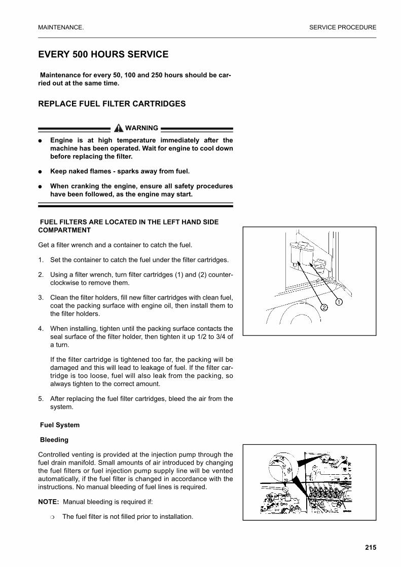
MAINTENANCE. SERVICE PROCEDURE
EVERY 500 HOURS SERVICE
Maintenance for every 50, 100 and 250 hours should be car-ried out at the same time.
REPLACE FUEL FILTER CARTRIDGES
WARNING
� Engine is at high temperature immediately after themachine has been operated. Wait for engine to cool downbefore replacing the filter.
� Keep naked flames - sparks away from fuel.
� When cranking the engine, ensure all safety procedureshave been followed, as the engine may start.
FUEL FILTERS ARE LOCATED IN THE LEFT HAND SIDE COMPARTMENT
Get a filter wrench and a container to catch the fuel.
1. Set the container to catch the fuel under the filter cartridges.
2. Using a filter wrench, turn filter cartridges (1) and (2) counter-clockwise to remove them.
3. Clean the filter holders, fill new filter cartridges with clean fuel,coat the packing surface with engine oil, then install them tothe filter holders.
4. When installing, tighten until the packing surface contacts theseal surface of the filter holder, then tighten it up 1/2 to 3/4 ofa turn.
If the filter cartridge is tightened too far, the packing will bedamaged and this will lead to leakage of fuel. If the filter car-tridge is too loose, fuel will also leak from the packing, soalways tighten to the correct amount.
5. After replacing the fuel filter cartridges, bleed the air from thesystem.
Fuel System
Bleeding
Controlled venting is provided at the injection pump through thefuel drain manifold. Small amounts of air introduced by changingthe fuel filters or fuel injection pump supply line will be ventedautomatically, if the fuel filter is changed in accordance with theinstructions. No manual bleeding of fuel lines is required.
NOTE: Manual bleeding is required if:
❍ The fuel filter is not filled prior to installation.
215

SERVICE PROCEDURE MAINTENANCE.
❍ Fuel injection pump is replaced.
❍ High pressure fuel line connections are loosened or fuellines replaced.
❍ Initial engine start up or start up after an extended periodof no engine operation.
❍ Vehicle fuel tank has been run until empty.
Low Pressure Lines and Fuel Filter(s)
Venting
1. Open the bleed screw
2. Operate the plunger on the lift pump until the fuel flowing fromthe fitting is free of air.
Tighten the bleed screw.Torque Value: 9 N•m
CAUTION
When using the starting motor to vent the system, do not engage it for more than 30 seconds at a time: Wait two (2) minutes between engagements.
WARNING
It is necessary to put the engine in the “Run” position. Be-cause the engine may start, be sure to follow all the safetyprecautions. Use the normal engine starting procedure.
216

MAINTENANCE. SERVICE PROCEDURE
High pressure Lines
Venting
WARNING
The pressure of the fuel in the line is sufficient to penetratethe skin and cause serious bodily harm.
1. Loosen the fittings at the injectors, and crank the engine toallow entrapped air to bleed from the lines. Tighten the fit-tings.
Re- Tighten Line FittingsTorque Value: 30 N•m
WARNING
Do not bleed a hot engine as this could cause fuel to spillonto a hot exhaust manifold creating a danger of fire.
2. Start the engine and vent one line at a time until the engineruns smoothly.
CHECK SWING PINION GREASE LEVEL, ADD GREASE
Prepare a scale.
1. Remove bolts (1) (2 bolts) on the top of the revolving frameand remove cover (A).
2. Check the colour of the grease. If it is milky white, it is neces-sary to change the grease. Please contact your Komatsu dis-tributor.
The total amount of grease is 33 L (29.7 kg).
3. Insert a rule into the grease and check that the depth of thegrease is at least 25 mm. Add more grease if necessary.
4. To add more grease replace cover (A) and (1) bolts (2 bolts),remove bolts (2) (2 bolts) on the top of the revolving frameand remove cover (B). Add more grease.
5. Replace cover (B) with bolts (2).
AM091710A
217

SERVICE PROCEDURE MAINTENANCE.
CHANGE OIL IN ENGINE OIL PAN, REPLACE ENGINE OIL FILTER CARTRIDGE
WARNING
The oil is at high temperature after the engine has been oper-ated, so never change the oil immediately after finishingoperations. Wait for the oil to cool down before changing it.
Prepare the following
� Container to catch drained oil: Min. 17 litres
� Refill capacity: 16 litres
� Filter wrench
1. Remove the inspection cover of the undercover directly underdrain valve (P) under the machine, then place a container tocatch the oil.
2. Remove cap from drain valve (P), fit drain hose from machinetoolkit and drain oil. After draining oil remove hose and refitcap.
3. Check the drained oil, and if there are excessive metal parti-cles or foreign material, please contact your distributor.
4. Tighten drain valve (P).
5. Using the filter wrench, turn filter cartridge (1) counterclock-wise to remove it. In particular, if this operation is carried out immediately afterstopping the engine, a large amount of oil will come out, sowait for 10 minutes before starting the operation.
6. Clean the filter holder.
REMARKConfirm that no remnants of old packing still adhere to the fil-
ter holder as this may result in oil leakage.
NOTICEDo not tighten filter or use any tools for installation be
cause this can damage the gasket and filter.
7. Fill the new filter with clean oil.
8. Install the new filter by applying a little engine oil to the sealand thread the filter on by hand by turning it clockwise untilhand tight.
9. After replacing the filter cartridge, add engine oil through oilfiller (F) until the oil level is between the H and L marks ondipstick (G).
For details of the oil to use, see “USE FUEL, COOLANTAND LUBRICANTS ACCORDING TO AMBIENT TEMPER-ATURE” on page 173.
218

MAINTENANCE. SERVICE PROCEDURE
NOTICEEven if the machine has not been operated for 500 hours,
the oil and filter cartridge must be replaced when themachine has been operated for 6 months.In the same way, even if the machine has not been operatedfor 6 months, the oil and filter cartidge must be replacedwhen the machine has been operated for 500 hours.
CLEAN AND INSPECT RADIATOR FINS, OIL COOLER FINS AND CONDENSER FINS (ONLY FOR MACHINES EQUIPPED WITH AIR-CONDITIONER)
WARNING
If compressed air, steam, or water hit your body directly,there is danger of injury. Always wear protective glasses,mask, and safety shoes.
1. Remove the engine hood and open rear door on the left sideof the machine. Loosen bolts (1) and remove the radiatorfront cover.
2. Blow off mud, dust or leaves clogging the radiator fins and oilcooler fins using compressed air.At the same time, clean the net in front of the oil cooler. Cleanthe condenser fins on machines equipped with the air condi-tioner. The condenser is located on the front of the radiator.Steam or water may be used instead of compressed air.
3. Check the rubber hose. Replace with a new one if the hose isfound to have cracks or to be hardened by ageing.Further, check hose clamps for looseness.
NOTICETo prevent damage to the fins, apply compressed air
from an appropriate distance. Damaged fins may cause
219

SERVICE PROCEDURE MAINTENANCE.
water leakage or overheating. In a dusty site, check the finsdaily, irrespective of the maintenance interval.
REPLACE HYDRAULIC TANK BREATHER ELE-MENT
WARNING
Wait for the oil to cool down before replacing the breatherelement. When removing the oil filler cap, turn it slowly torelease the internal pressure, then remove it carefully.
1. Remove the cap of oil filter (F).
2. Replace element (1) inside the cap with a new one.
REPLACE HYDRAULIC FILTER ELEMENT
WARNING
When removing the oil filler cap, turn it slowly to release theinternal pressure before removing it.
1. Remove the cap from oil filler (F), and release the internalpressure.
2. Loosen 4 bolts, then remove cover (1).When doing this, the cover may fly out under the force ofspring, so hold the cover down when removing the bolts.
3. After removing spring (2) and valve (3) take out element (4).
4. Clean the removed parts in diesel oil.
5. Install a new element in the place where old element (4) wasinstalled.
6. Set valve (3) and spring (2) on top of the element.
7. Set cover (1) in position, push it down by hand, and install thecover with the mounting bolts.
8. Screw in the oil filler cap and install the cover.
9. To bleed the air, start the engine according, see “STARTINGENGINE” on page 110. and run the engine at low idling for 10minutes.
220

MAINTENANCE. SERVICE PROCEDURE
10. Stop the engine.
REMARKOperate the machine after halting for more than 5 minutes to
eliminate bubbles in the oil inside the tank.
11. Check for oil leakage and wipe off any spilled oil.
When the hydraulic breaker is installed, the hydraulic oil deterio-rates earlier than in normal bucket digging work.
The first element replacement should be at 100 to 150 hours fornew machines. Thereafter, replace the element according to thetable on the right.
EVERY 1000 HOURS SERVICE
Maintenance for every 100, 250 and 500 hours should be car-ried out at the same time.
CHANGE OIL IN SWING MACHINERY CASE
WARNING
The oil is at high temperature immediately after the machinehas been operated. Wait for the oil to cool down before carry-ing out maintenance.
� Container to catch drained oil: Min. 2.5 l capacity
� Refill capacity: 2.5 l
1. Set an oil container under drain plug (P) under the machinebody.
2. Loosen drain valve (P) under the body, drain the oil, thentighten (98 - 185 Nm (10-19kgm)) the drain valve again.
AD31373D
Replacement intervalfor hydraulic oil
Breaker operation (ratio %)Hydraulic
FillerelementR
epla
cem
ent i
nter
val (
H)
(When using breaker only
(When notusing breaker)
221
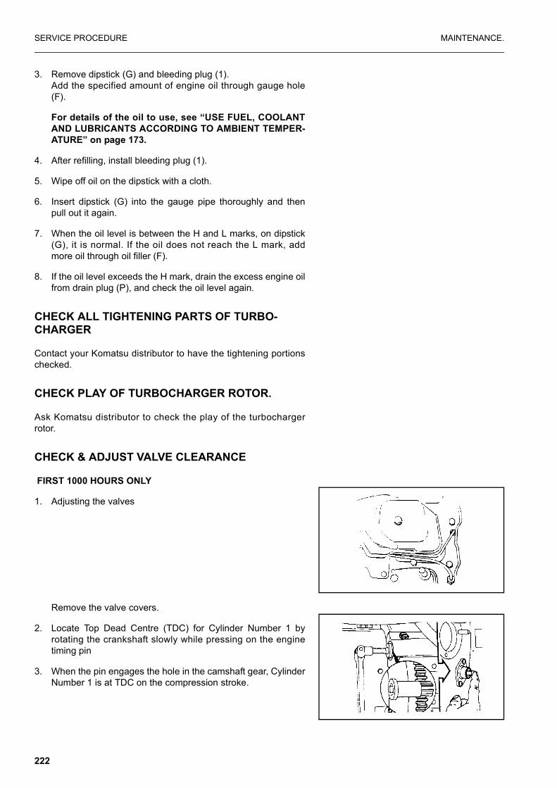
SERVICE PROCEDURE MAINTENANCE.
3. Remove dipstick (G) and bleeding plug (1).Add the specified amount of engine oil through gauge hole(F).
For details of the oil to use, see “USE FUEL, COOLANTAND LUBRICANTS ACCORDING TO AMBIENT TEMPER-ATURE” on page 173.
4. After refilling, install bleeding plug (1).
5. Wipe off oil on the dipstick with a cloth.
6. Insert dipstick (G) into the gauge pipe thoroughly and thenpull out it again.
7. When the oil level is between the H and L marks, on dipstick(G), it is normal. If the oil does not reach the L mark, addmore oil through oil filler (F).
8. If the oil level exceeds the H mark, drain the excess engine oilfrom drain plug (P), and check the oil level again.
CHECK ALL TIGHTENING PARTS OF TURBO-CHARGER
Contact your Komatsu distributor to have the tightening portionschecked.
CHECK PLAY OF TURBOCHARGER ROTOR.
Ask Komatsu distributor to check the play of the turbochargerrotor.
CHECK & ADJUST VALVE CLEARANCE
FIRST 1000 HOURS ONLY
1. Adjusting the valves
Remove the valve covers.
2. Locate Top Dead Centre (TDC) for Cylinder Number 1 byrotating the crankshaft slowly while pressing on the enginetiming pin
3. When the pin engages the hole in the camshaft gear, CylinderNumber 1 is at TDC on the compression stroke.
222

MAINTENANCE. SERVICE PROCEDURE
CAUTION
Be sure to disengage the pin after locating TDC.
Valve clearance intake: 0-254 mmexhaust: 0-508 mm
Check/set valves with engine cold - below 60°C
NOTE: The clearance is correct when some resitance is ‘felt’when the feeler gauge is slipped between the valve stemand the rocker lever.
With the engine in TDC position, check and adjust the followingvalve clearances.
Intake (I) cylinders: 1,2Exhaust (E) cylinders: 1,3
1 Camshaft gear
2 Engine timing pin
3 Gear housing
223

SERVICE PROCEDURE MAINTENANCE.
Tighten the lock nut to 24 N.m and re-check the valve lash
Mark the pulley and rotate the crankshaft 360° degrees. Be sure timing pin is sisengaged, before rotating.The timing pin will not engage in this position. With the engine inthis position, check and adjust the following valve clearances.
Intake (I) cylinders: 3,4Exhaust (E) cylinders: 2,4
Tighten the lock nut to 24 N.m and re-check the valve lash.Install the valve covers and tighten capscrews to 24 N.m
CHECK FAN BELT TENSIONER BEARING BELT AND FAN HUB
� Check the tensioner bearingWith the fan belt removed rotate fan hub.The tensioner pulley should spin freely with no rough spotsdefected under hand pressure.
� Check the tensioner bearing.
� Replace bearing if damaged.
� Check fan hub. With the drive belt removed, rotate fan hub.
NOTE: The fan hub should spin freely without excessive endplay.
� Check the fan hub bearing.
� Replace bearing if damaged.
CHECK FAN BELT TENSION
� Measure the belt deflection at the longest span of the belt.
� Maximum deflection: 9.5-12,7 mmIf tension is low (deflection is outside range): (see “Check fanbelt tensioner bearing, belt and fan hub.”)
� Check belt & replace if damaged.
� Check tensioner & replace if damaged.
224

MAINTENANCE. SERVICE PROCEDURE
EVERY 2000 HOURS SERVICE
Maintenance for every 100, 250, 500 and 1000 hours should be carried out at the same time.
CLEAN HYDRAULIC TANK STRAINER
WARNING
The oil is at high temperature immediately after the machinehas been operated. Wait for the oil to cool down beforechanging the oil. When removing the oil filler cap, turn itslowly to release the internal pressure, then remove it care-fully.
Prepare the following
� Container to catch drained oil: min. 117 l capacity
� Refill, capacity: 117 l
� Prepare a handle for the socket wrench set.
1. Loosen 4 bolts, then remove cover (1).When doing this, the cover may fly out under the force ofspring (2), so push the cover down when removing the bolts.
2. Pull up the top of rod (3), and remove spring and strainer (4).
3. Remove the dirt stuck to strainer (4), then wash it in clean die-sel oil or flushing oil. If strainer (4) is damaged, replace it witha new one.
4. Refit strainer (4) by inserting it into tank projecting part (5).
5. Install cover (1) with bolts.
CLEAN, CHECK TURBOCHARGER
Contact your Komatsu distributor for cleaning or inspection.
CHECK ALTERNATOR, STARTING MOTOR
The brush may be worn, or the bearing may have run out ofgrease, so contact your Komatsu distributor for inspection orrepair. If the engine is started frequently, carry out inspectionevery 1000 hours.
225

SERVICE PROCEDURE MAINTENANCE.
CHECK VIBRATION DAMPER
Check the index lines (A) on the damper hub (B) and the inertiamember (C). If the lines are more than 1.59 mm out of alignment,replace the damper.
CHANGE OIL IN AXLES
1. Remove plugs (1) and (2) to drain oil.
2. Replace plug (2).
3. Attach tube and funnel to plug (1) hole and add oil until oilemerges when tube is removed.
4. Replace plug (1).
Vibration damper
226

MAINTENANCE. SERVICE PROCEDURE
CHANGE OIL IN HUBS
1. Position hub with plug (1) at bottom and remove plug (1).
2. When all oil has drained out, rotate hub until plug hole is atthe top.
3. Add oil (2.5 l each hub, front axle, 2.7 l each hub, rear axle)and rotate hub until filling hole is horizontal.
4. If oil emerges, allow excess to drain off and replace plug.
5. If no oil emerges, rotate hub until plug hole is at the top andadd oil.
6. Rotate until hole is horizontal.
7. Repeat steps 4,5 + 6.
8. Replace plug.
CHANGE OIL IN TRANSMISSION ASSEMBLY
TRANSMISSION
1. Remove plugs (1), (2) + (3) and allow oil to drain out.
2. Replace plug (3).
3. Add oil (approx. 1 l) until oil emerges from plug (2) hole.
4. Replace plugs (1) + (2).
CLUTCH
1. Remove plugs (4), (5) & (6) and allow oil to drain out.
2. Replace plugs (5) & (6).
3. Add oil (measure 0.5 l)
4. Replace plug (4).
CHANGE ANTIFREEZE
Follow the procedure of “CLEAN INSIDE OF COOLINGSYSTEM” on page 189 for draining and refilling the cool-ing system.
CHECK AND ADJUST VALVE CLEARANCE
See section “CHECK & ADJUST VALVE CLEARANCE” onpage 222 for procedure.
Fill port
Drain ports
227

SERVICE PROCEDURE MAINTENANCE.
EVERY 4000 HOURS SERVICE
Maintenance for every 100, 250, 500, 1000 and 2000 hours should be carried out at the same time.
CHECK WATER PUMP
Check that there is oil leakage, water leakage, or clogging of thedrain hole. If any abnormality is found, contact your Komatsu dis-tributor for disassembly and repair or replacement.
EVERY 5000 HOURS SERVICEMaintenance for every 100, 250, 500 and 1000 hours should becarried out at the same time.
CHANGE OIL IN HYDRAULIC TANK
WARNING
The oil is at high temperature immediately after the machinehas been operated. Wait for the oil to cool down beforechanging the oil. When removing the oil filler cap, turn itslowly to release the internal pressure, then remove it care-fully.
Prepare the following
� Container to catch drained oil: min. 117 l capacity
� Refill, capacity: 117 l
� Prepare a handle for the socket wrench set.
1. Swing the upper structure so that the drain plug under thehydraulic tank overhangs the undercarriage.
228

MAINTENANCE. SERVICE PROCEDURE
2. Retract the arm and bucket cylinders to the stroke end, thenlower the boom and put the bucket teeth in contact with theground.
3. Lock the control lever pad safety lock lever and stop theengine.
4. Remove the cover over the hydraulic tank and remove thecap of oil filler (F).
5. Set the oil container under the drain plug under the machine.Using the handle, remove drain plug (P) and drain the oil.Check the O-ring installed to plug (P), and if it is.damaged,replace the O-ring. After draining the oil, tighten drain plug(P). Tightening torque: 69 ± 10 Nm (7 ± 1 kgm).
When removing drain plug (P), be careful not to get oil on your-self.
6. Add the specified amount of engine oil through oil filler port(F) Check that the oil level is between H and L on the sightgauge.
For type of oil to be used, see “USE FUEL, COOLANTAND LUBRICANTS ACCORDING TO AMBIENT TEMPER-ATURE” on page 173.
NOTICEWhen the hydraulic breaker is installed, the hydraulic oil
deteriorates earlier than in normal bucket digging work.Therefore replace the hydraulic oil according to the table atthe right.
7. After replacing hydraulic oil or replacing filter element andstrainer, bleed air from the circuit according to the followingprocedure.
AD31373D
Replacement intervalfor hydraulic oil
Breaker operation (ratio %)Hydraulic
Fillerelement
Rep
lace
men
t int
erva
l (H
)
(When using breaker only
(When notusing breaker)
229
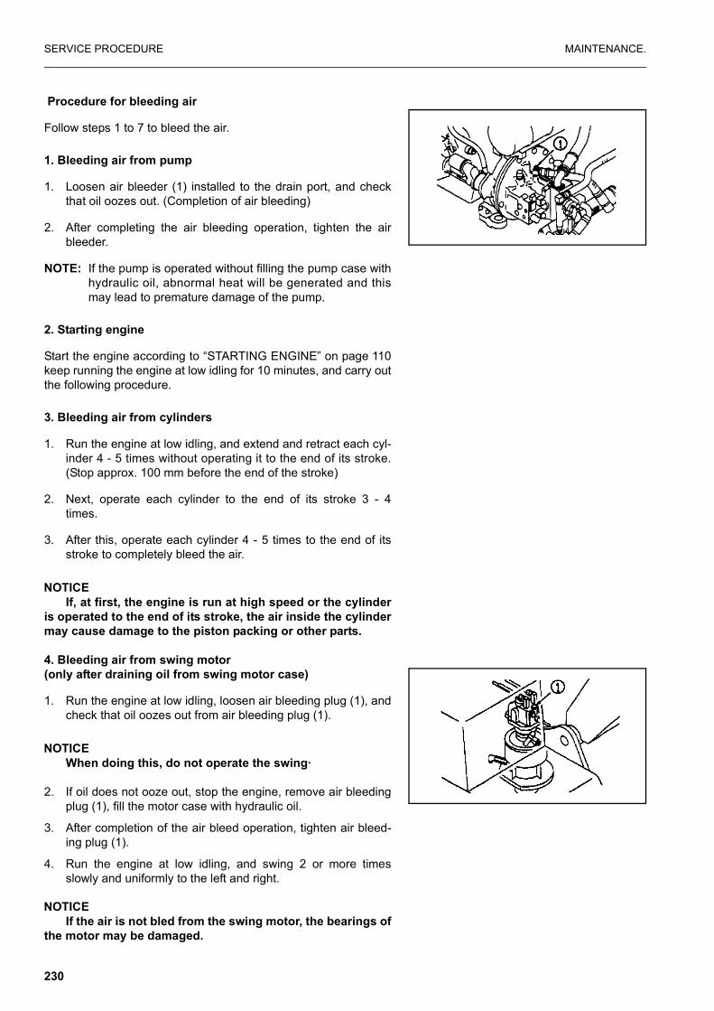
SERVICE PROCEDURE MAINTENANCE.
Procedure for bleeding air
Follow steps 1 to 7 to bleed the air.
1. Bleeding air from pump
1. Loosen air bleeder (1) installed to the drain port, and checkthat oil oozes out. (Completion of air bleeding)
2. After completing the air bleeding operation, tighten the airbleeder.
NOTE: If the pump is operated without filling the pump case withhydraulic oil, abnormal heat will be generated and thismay lead to premature damage of the pump.
2. Starting engine
Start the engine according to “STARTING ENGINE” on page 110keep running the engine at low idling for 10 minutes, and carry outthe following procedure.
3. Bleeding air from cylinders
1. Run the engine at low idling, and extend and retract each cyl-inder 4 - 5 times without operating it to the end of its stroke.(Stop approx. 100 mm before the end of the stroke)
2. Next, operate each cylinder to the end of its stroke 3 - 4times.
3. After this, operate each cylinder 4 - 5 times to the end of itsstroke to completely bleed the air.
NOTICEIf, at first, the engine is run at high speed or the cylinder
is operated to the end of its stroke, the air inside the cylindermay cause damage to the piston packing or other parts.
4. Bleeding air from swing motor(only after draining oil from swing motor case)
1. Run the engine at low idling, loosen air bleeding plug (1), andcheck that oil oozes out from air bleeding plug (1).
NOTICEWhen doing this, do not operate the swing·
2. If oil does not ooze out, stop the engine, remove air bleedingplug (1), fill the motor case with hydraulic oil.
3. After completion of the air bleed operation, tighten air bleed-ing plug (1).
4. Run the engine at low idling, and swing 2 or more timesslowly and uniformly to the left and right.
NOTICEIf the air is not bled from the swing motor, the bearings of
the motor may be damaged.
230

SPECIFICATIONS.
231

SPECIFICATIONS SPECIFICATIONS.
SPECIFICATIONS
* Weight will vary depending on specification
** 20 km/h specification version.
WEIGHT
� Operation weight (without operator * 13100 kg
PERFORMANCE
� Bucket capacity (standard bucket) SAE/CECE 0.44 m³/0.40 m³
� With of opening(standard bucket) 833 mm
(with side cutter) 954 mm
� Travel speed
Low speed 3.5 km/h / 2.7 km/h**
middle speed 10 km/h / 8 km/h**
High speed 30 km/h / 20 km/h**
� Swing speed 12.5 rpm
ENGINE
� Model Komatsu SA4D102E-1 diesel engine
� Flywheel horsepower (NET) 76 kW (102 HP)/2250 rpm
� Starting motor 24 V 5.5 kW
� Alternator 24 V 45 A
� Battery 12 V 95 Ah x 2 pieces
232

SPECIFICATIONS. SPECIFICATIONS
1 - PIECE BOOM
233

SPECIFICATIONS SPECIFICATIONS.
2 - PIECE BOOM
234

SPECIFICATIONS. SPECIFICATIONS
WORKING RANGE: ONE PIECE BOOM
Arm length mm (Tt/In) 2100 2500
A Max.digging height 8660 8900
B Max.dumping height 6290 6530
C Max digging depth 4730 5130
D Max.vertical wall digging 4175 4560
E Max. digging depth of cut for 8’ level 4495 4925
F Max. digging reach 7895 8265
F’ Max digging reach at ground level 7690 8070
H Min. swing radius 2320 2400.
235

SPECIFICATIONS SPECIFICATIONS.
WORKING RANGE: TWO PIECE BOOM
Arm length mm (Tt/In) 2100 2500
A Max.digging height 8930 9190
B Max.dumping height 6540 6905
C Max digging depth 5010 5411
D Max.vertlcal wall digging 3978 4365
E Max. digging depth of cut for 8’ level 4779 5202
F Max. digging reach 8142 8518
F’ Max digging reach at ground level 7945 8331
H Min. swing radius 2605 2650
236

OPTIONS, ATTACHMENTS
237

GENERAL PRECAUTIONS OPTIONS, ATTACHMENTS
GENERAL PRECAUTIONS
PRECAUTIONS RELATED TO SAFETYIf attachments or options other than those authorized by Komatsuare installed, this will not only affect the life of the machine, butwill also cause problems with safety.
When installing attachments not listed in this Operation and Main-tenance Manual, please contact your Komatsu distributor first.
If you do not contact Komatsu, we cannot accept any responsibil-ity for any accident or failure.
WARNING
Precautions for removal and installation operationsWhen removing or installing attachments, obey the following precautions and take care to ensure safety during the opera-tion.
� Carry out the removal and installation operations on aflat, firm ground surface.
� When the operation is carried out by two or more work-ers, determine signals and follow these during the opera-tion.
� When carrying heavy objects (more than 25 kg), use acrane.
� When removing heavy parts, always support the partbefore removing it. When lifting such heavy parts with a crane, always paycareful attention to the position of the centre of gravity.
� It is dangerous to carry out operations with the load keptsuspended. Always set the load on a stand, and checkthat it is safe.
� When removing or installing attachments, make sure thatthey are in a stable condition and will not fall over.
� Never go under a load suspended from a crane.Always stand in a position that is safe even if the loadshould fall.
NOTICEQualifications are required to operate a crane. Never
allow the crane to be operated by unqualified person.For details of the removal and installation operations, pleasecontact your Komatsu distributor.
238

OPTIONS, ATTACHMENTS GENERAL PRECAUTIONS
PRECAUTIONS WHEN INSTALLING ATTACHMENTS
WARNING
� Long work equipment reduces the stability of the chas-sis, so if the swing is operated on a slope, or when goingdown a steep hill, the machine may lose its balance andoverturn. The following operations are particularly dan-gerous, so never operate the machine in these ways.
� Going downhill with the work equipment raised
� Traveling across slopes
� Swinging the upper structure on slopes
� If heavy work equipment is installed, the overrun of theswing becomes greater (the distance from the pointwhere the operator operates the control levers to stopthe swing to the point where the upper structure stopscompletely), so there is danger of mistaking the distanceand hitting something.Always operate so that there is an ample margin to thestopping point. Furthermore, the hydraulic drift also becomes largerwhen the work equipment is stopped in mid-air, it willgradually move down under its own weight).
� Always follow the correct procedure when installing theboom and arm. If the correct procedure is not followed,this may lead to serious damage or injury, so please con-sult your Komatsu distributor before carrying out instal-lation.
� If long work equipment is installed, the working rangewill suddenly become larger, so there is danger of mis-taking the distance and hitting something.Always operate the work equipment so that there isample space from any obstacles in the area
INCORRECT
CORRECT
INCORRECT CORRECTPlatform
239

HANDLING BUCKET WITH HOOK OPTIONS, ATTACHMENTS
HANDLING BUCKET WITH HOOK
CHECKING FOR DAMAGE TO BUCKET WITH HOOKCheck that there is no damage to the hook, stopper, or hookmount. If any abnormality is found, please contract your Komatsudistributor.
PROHIBITED OPERATIONSThe standard work equipment must not be used for lifting loads. Ifthis machine is to be used for lifting loads, it is necessary to installthe special bucket with hook.
PRECAUTIONS DURING OPERATIONS� When carrying out lifting operations, reduce the engine speed
and use the lifting operation mode.
� Depending on the posture of the work equipment, there isdanger that the wire or load may slip off the hook. Always becareful to maintain the correct hook angle to prevent this fromhappening.
� Never steer the machine while lifting a load.
� If the bucket with hook is turned and used for operations, itwill hit the arm during dumping operations, so be carefulwhen using it.
� The loads must never exceed those specified in the liftingcapacity chart when carrying out lifting operations.
� If you wish to install a hook in the future, please contact yourKomatsu distributor.
AL069260A
CORRECT
AL069270A
INCORRECT
240
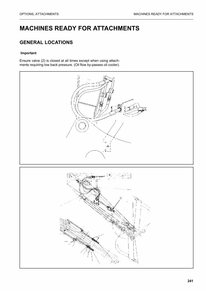
OPTIONS, ATTACHMENTS MACHINES READY FOR ATTACHMENTS
MACHINES READY FOR ATTACHMENTS
GENERAL LOCATIONS
Important
Ensure valve (2) is closed at all times except when using attach-ments requiring low back pressure. (Oil flow by-passes oil cooler).
241

MACHINES READY FOR ATTACHMENTS OPTIONS, ATTACHMENTS
1. STOP VALVE (1)
This valve stops the flow of the hydraulic oil.
(1) FREE: Hydraulic oil flows.
(2) LOCK: Hydraulic oil stops.
When removing or installing attachments, set this valve to theLOCK position.
2. SELECTOR VALVE (2)
This switches the flow of the hydraulic oil.
Position (1): When breaker is used
Position (2): When general attachment is used (crusher, etc.)
3. CONTROL PEDAL (3)
This is used to operate the attachment.
Pedal for two line attachment (with auto deceleration mechanism)
The breaker is operated with right pedal (1).
4. ACCUMULATOR (FOR CONTROL CIRCUIT) (4)
WARNING
The accumulator is charged with high-pressure nitrogen gas,and it is extremely dangerous if it is handled mistakenly.
For details of handling, see “HANDLING ACCUMULA-TOR” on page 246.
This is installed to release any remaining pressure in the attach-ment circuit after the engine is stopped. Normally, do not touch it.
A To/from main valve
B 1 way flow to tank (breaker)
C To tank
D 2 way flow position (normal)
E From boom piping
242

OPTIONS, ATTACHMENTS MACHINES READY FOR ATTACHMENTS
HANDLING THE CLAMSHELL BUCKET
This bucket is used for digging and loading in side-ditches or confined spaces.
How to install clamshell bucket
1. Clamshell cylinder head
2. Clamshell cylinder bottom
3. Rotate left
4. Rotate right
Ensure valve (A) (both sides) is closed and valve (B) is open(both sides)
How to operate
Open and close
Move the right working equipment lever to operate clamshell
3. Open
4. Close
Rotate
243
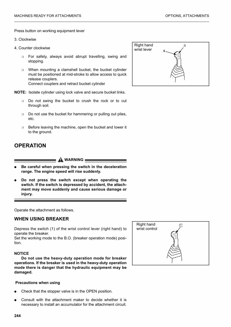
MACHINES READY FOR ATTACHMENTS OPTIONS, ATTACHMENTS
Press button on working equipment lever
3. Clockwise
4. Counter clockwise
❍ For safety, always avoid abrupt travelling, swing andstopping.
❍ When mounting a clamshell bucket, the bucket cylindermust be positioned at mid-stroke to allow access to quickrelease couplers.Connect couplers and retract bucket cylinder
NOTE: Isolate cylinder using lock valve and secure bucket links.
❍ Do not swing the bucket to crush the rock or to cutthrough soil.
❍ Do not use the bucket for hammering or pulling out piles,etc.
❍ Before leaving the machine, open the bucket and lower itto the ground.
OPERATION
WARNING
� Be careful when pressing the switch in the decelerationrange. The engine speed will rise suddenly.
� Do not press the switch except when operating theswitch. If the switch is depressed by accident, the attach-ment may move suddenly and cause serious damage orinjury.
Operate the attachment as follows.
WHEN USING BREAKER
Depress the switch (1) of the wrist control lever (right hand) tooperate the breaker. Set the working mode to the B.O. (breaker operation mode) posi-tion.
NOTICEDo not use the heavy-duty operation mode for breaker
operations. If the breaker is used in the heavy-duty operationmode there is danger that the hydraulic equipment may bedamaged.
Precautions when using
� Check that the stopper valve is in the OPEN position.
� Consult with the attachment maker to decide whether it isnecessary to install an accumulator for the attachment circuit.
Right hand wrist lever
Right handwrist control
244

OPTIONS, ATTACHMENTS MACHINES READY FOR ATTACHMENTS
� For details of other precautions when handling the breaker,read and use correctly the instruction manual provided by thebreaker manufacturer.
� When using the breaker, the hydraulic oil deteriorates morerapidly than for normal operations, so change the hydraulic oiland replace the element at a shorter interval.
For details, see “MAINTENANCE WHEN USING HYDRAU-LIC BREAKER” on page 186.
Open
245

MACHINES READY FOR ATTACHMENTS OPTIONS, ATTACHMENTS
HANDLING ACCUMULATOR
WARNING
On machines equipped with an accumulator, for a short time after the engine is stopped, if the work equipment control lever is moved to the LOWER position, the work equipment will move down under its own weight.
After stopping the engine, always place the control lever pad safety lock in the LOCK position and lock the attachment control pedal with the lock pin.
The accumulator is filled with high-pressure nitrogen gas, and it is extremely dangerous if it is handled in the wrong way. Always observe the following precautions.
� Never make any hole in the accumulator or expose it toflame or fire.
� Do not weld anything to the accumulator.
� When disposing of the accumulator, it is necessary torelease the gas from the accumulator, so please contactyour Komatsu distributor.
This machine is equipped with the accumulators in the controland brake circuit. The accumulator is a device to store the pres-sure in the control and brake circuit, and when installed, the brakeand control circuit can be operated for a short time even after theengine is stopped. Therefore, if the control lever is moved in thedirection to lower the work equipment, it is possible for the workequipment to move under its own weight. Also it is possible tostop the machine.
The accumulators are installed in the position shown in the dia-gram on the right and below.
246

OPTIONS, ATTACHMENTS MACHINES READY FOR ATTACHMENTS
METHOD FOR RELEASING PRESSURE IN CON-TROL CIRCUIT OF MACHINES EQUIPPED WITH ACCUMULATOR
1. Lower the work equipment to the ground. Close any attach-ment such as the crusher.
2. Stop the engine.
3. Set the lock control lever pad safety lock completely in theFREE position, operate the work equipment control lever andattachment control pedal fully to the front, rear, left, and right,to release the pressure in the control circuit.
4. Set the lock control lever pad safety lock completely in theLOCK position, then lock the control levers and attachmentcontrol pedal. Note that this does not completely release thepressure, so when removing the accumulator in the controlcircuit, loosen the connections slowly and do not stand in thedirection where the oil spurs out.
LONG-TERM STORAGEIf the machine is not to be used for a long time, do as follows.
� Set the stop valve in the LOCK condition.
� Install a blind plug to the valve.
� Set the selector valve to the position for general attachmentssuch as the crusher.
If there is no breaker or general attachment installed, operatingthe pedal may cause overheating.
SPECIFICATIONS
Hydraulic specifications
� Oil flow
� Cracking pressure of safety valveWhen using breaker: 17200 kPa (175 kg/cm²).
Working mode
Clamshell rotation Breaker
60l /min 206l /min.
247

INTRODUCTION OF ATTACHMENTS AND EXTENDING MACHINE SERVICE LIFE OPTIONS, ATTACHMENTS
INTRODUCTION OF ATTACHMENTS AND EXTENDING MACHINE SERVICE LIFE
This section describes the necessary precautions to be observedwhen operating a hydraulic excavator equipped with an attach-ment.
NOTICESelect the attachment most suited to the machine body.
� The machine models to which attachments can be mounted vary. For selection of attachment and machine model, consult your Komatsu distributor.
HYDRAULIC BREAKER MAIN FIELDS OF APPLICATION
� Crushed rock
� Demolition work
� Road construction
This attachment can be used for a wide range of work includingdemolition of buildings, breaking up of road surfaces, tunnel work,breaking up slag, rock crushing, and breaking operations in quar-ries.
Keep the chisel pushed perpendicularly against the impact sur-face when carrying out breaking operations.
When applying impact, push the chisel against the impact surfaceand operate so that the chassis rises approx. 5 cm off the ground.Do not let the machine come further off the ground than neces-sary.
AL069750A
AL069760A
90
90
248

OPTIONS, ATTACHMENTS INTRODUCTION OF ATTACHMENTS AND EXTENDING MACHINE SERVICE LIFE
When applying continuous impact to the same impact surface, ifthe chisel does not penetrate or break the surface within 1minute, change the point of impact and carry out breaking opera-tions closer to the edge.
The direction of penetration of the chisel and the direction of thebreaker body will gradually move out of line with each other, soalways adjust the bucket cylinder to keep them aligned.
Always keep the chisel pressed against the impact surface prop-erly to prevent using the impact force when there is no resistance.
MISTAKEN METHODS OF USE
To ensure that the machine has a long life, and to ensure thatoperations are carried out in safety, do not operate the machine inany of the following ways.
� Do not operate the cylinder to the end of its stroke.Always leave approx. 5 cm to spare.
Using the mount to gather in pieces of rock
Operations using the swing force
AL069780A
AL069800A
AL069810A
249
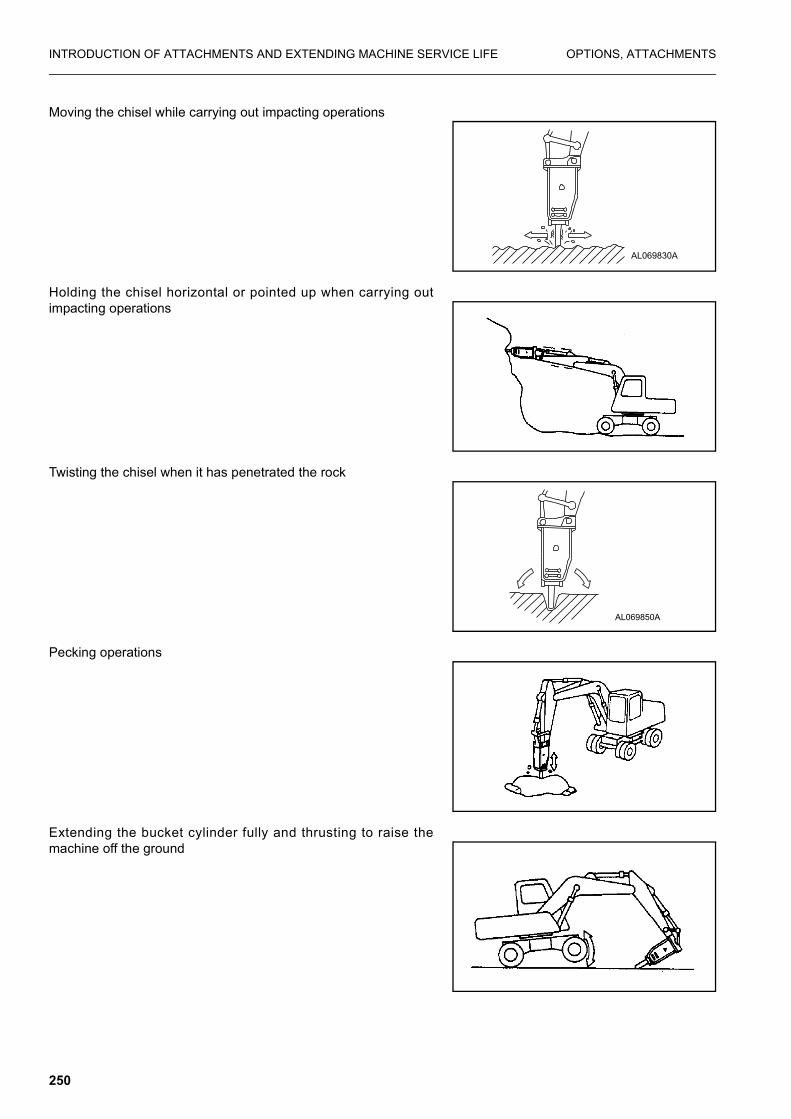
INTRODUCTION OF ATTACHMENTS AND EXTENDING MACHINE SERVICE LIFE OPTIONS, ATTACHMENTS
Moving the chisel while carrying out impacting operations
Holding the chisel horizontal or pointed up when carrying outimpacting operations
Twisting the chisel when it has penetrated the rock
Pecking operations
Extending the bucket cylinder fully and thrusting to raise themachine off the ground
AL069830A
AL069850A
250

OPTIONS, ATTACHMENTS INTRODUCTION OF ATTACHMENTS AND EXTENDING MACHINE SERVICE LIFE
POWER RIPPER MAIN FIELDS OF APPLICATIONS
� Road repair work
� Demolition work
This attachment can be used for a wide range of work includingpeeling off and crushing pavement roads, demolishing woodenhouses and buildings, and crushing foundation and roadbeds.
MISTAKEN METHODS OF USE
To ensure that the machine has a long life, and to ensure thatoperations are carried out in safety, do not operate the machine inany of the following ways.
� Do not operate the cylinder to the end of its stroke.Always leave approx. 5 cm to spare.
Impact operations using attachment
Impact operations using swing force
Overloading work equipment during lifting and loading operations
AM092190A
251

INTRODUCTION OF ATTACHMENTS AND EXTENDING MACHINE SERVICE LIFE OPTIONS, ATTACHMENTS
Operations using attachment to grip at an angle.
FORK GRAB MAIN FIELDS OF APPLICATION
� Disposing of industrial waste
� Disposing of demolition waste
This can be used for a wide range of work including collecting orloading demolition waste materials and debris, timber, grass.
MISTAKEN METHODS OF USE
To ensure that the machine has a long life, and to ensure thatoperations are carried out in safety, do not operate the machine inany of the following ways.
� Do not operate the cylinder to the end of its stroke.Always leave approx. 5 cm to spare.
Operations using the swing force
Operations using one side of work equipment
AM092240A
AM092250A
AM092260A
252

OPTIONS, ATTACHMENTS INTRODUCTION OF ATTACHMENTS AND EXTENDING MACHINE SERVICE LIFE
Pushing fork into ground surface to jack up and change directionof machine
Impact operation with no load.
GRAPPLE BUCKET MAIN FIELDS OF APPLICATION
� Demolition
� Disposing of industrial waste
� Forestry
This bucket is widely used for demolition including breaking-upwork, grading and digging, clean-up work after natural disasters,dumping industrial waste, and forestry work, etc.
MISTAKEN METHODS OF USE
To ensure that the machine has a long life, and to ensure thatoperations are carried out in safety, do not operate the machine inany of the following ways.
� Do not operate the cylinder to the end of its stroke.Always leave approx. 5 cm to spare.
Operations using the swing force
AM092280A
AM092290A
253

INTRODUCTION OF ATTACHMENTS AND EXTENDING MACHINE SERVICE LIFE OPTIONS, ATTACHMENTS
Grabbing a object using buckets on only one side
Closing the sub-bucket with the boom and arm fully extended.
Impact operation with no load.
SCRAP GRAPPLE MAIN FIELDS OF APPLICATION
� Disposal of rock or debris
This attachment is mounted to the arm end and used to grasprock, debris etc. by opening and closing the claws (3 to 5) corre-sponding to the extension and retraction of the hydraulic cylinder.
MISTAKEN METHODS OF USE
To ensure that the machine has a long life, and to ensure thatoperations are carried out in safety, do not operate the machine inany of the following ways.
AM092310A
AM092340A
254

OPTIONS, ATTACHMENTS INTRODUCTION OF ATTACHMENTS AND EXTENDING MACHINE SERVICE LIFE
� Do not operate the cylinder to the end of its stroke.Always leave approx. 5 cm to spare.
Operations using the swing force
Operations using one side of work equipment
Catching and dragging with claw end
Gouging.
AM092360A
255
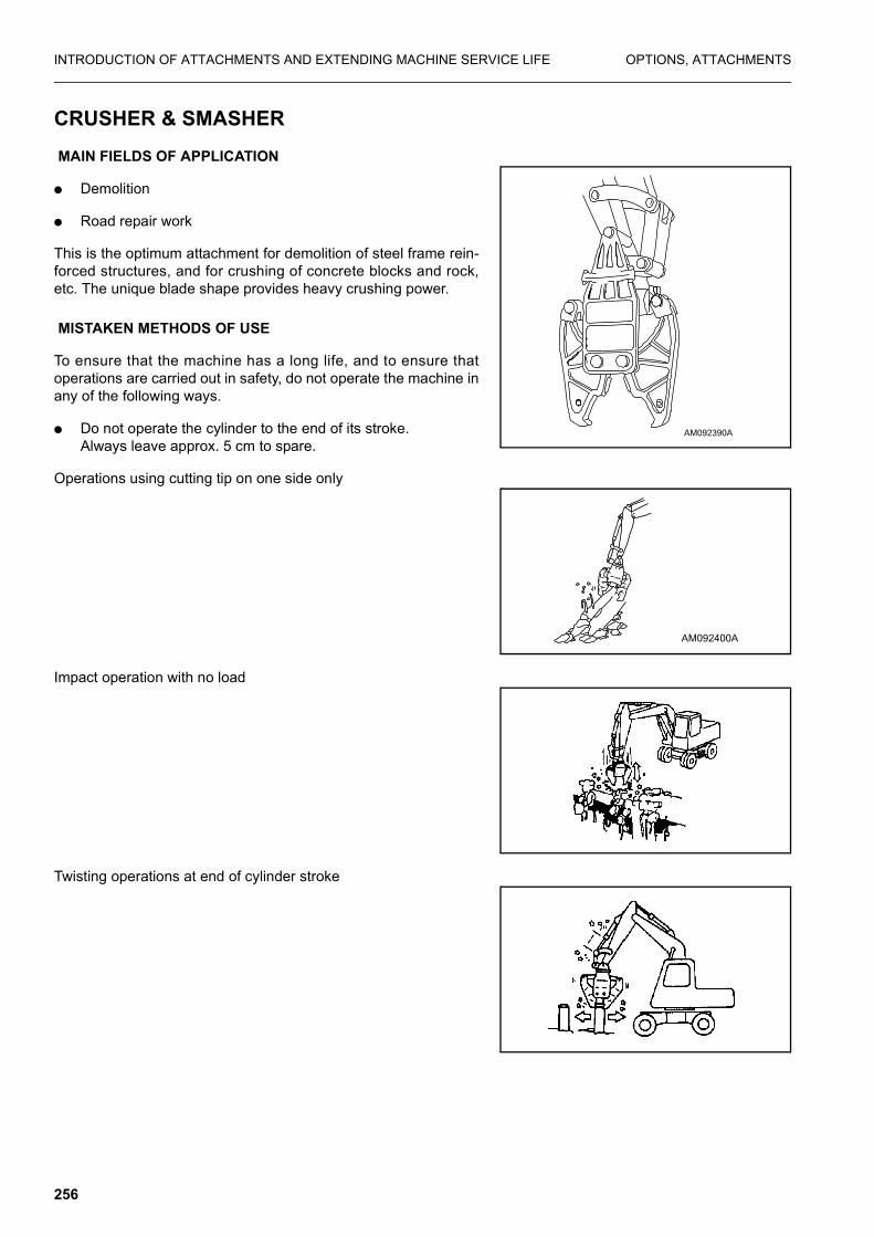
INTRODUCTION OF ATTACHMENTS AND EXTENDING MACHINE SERVICE LIFE OPTIONS, ATTACHMENTS
CRUSHER & SMASHER MAIN FIELDS OF APPLICATION
� Demolition
� Road repair work
This is the optimum attachment for demolition of steel frame rein-forced structures, and for crushing of concrete blocks and rock,etc. The unique blade shape provides heavy crushing power.
MISTAKEN METHODS OF USE
To ensure that the machine has a long life, and to ensure thatoperations are carried out in safety, do not operate the machine inany of the following ways.
� Do not operate the cylinder to the end of its stroke.Always leave approx. 5 cm to spare.
Operations using cutting tip on one side only
Impact operation with no load
Twisting operations at end of cylinder stroke
AM092390A
AM092400A
256

OPTIONS, ATTACHMENTS INTRODUCTION OF ATTACHMENTS AND EXTENDING MACHINE SERVICE LIFE
Sudden gripping and breaking operations.
HYDRAULIC PILE DRIVER MAIN FIELDS OF APPLICATION
� Foundation work
� River work
� Water supply and sewerage
This is a piling machine employing the hydraulic power source ofthe excavator. The machine features a long arm and a chuck unitThis facilitates operations such as driving and movable by 360°orners, vertical driving e removing long piles, driving in piles atcorners, vertical driving etc.
MISTAKEN METHODS OF USE
To ensure that the machine has a long life, and to ensure thatoperations are carried out in safety; do not operate the machine inany of the following ways.
� Do not operate the cylinder to the end of its stroke.Always leave approx. 5 cm to spare.
Forward or swing motion while grasping a pile
Lifting more than two piles at the same time
AM092430A
AM092440A
257

INTRODUCTION OF ATTACHMENTS AND EXTENDING MACHINE SERVICE LIFE OPTIONS, ATTACHMENTS
Work other than standard works
Loading or unloading a machine equipped with hydraulic piledriver.
HYDRAULIC EXCAVATOR WITH MULTIPURPOSE CRANE MAIN FIELDS OF APPLICATION
� Site preparation
� Water supply and sewerage
� River work
� Agricultural, civil engineering work
Crane operation can be carried out without removing the bucket.This machine is used for laying U section gutters and hume pipesfor water supply and sewerage as well as river and canal work,agricultural, civil engineering work and site preparation.
MISTAKEN METHODS OF USE
To ensure that the machine has a long life, and to ensure thatoperations are carried out in safety, do not operate the machine inany of the following ways.
� Do not operate the cylinder to the end of its stroke.Always leave approx. 5 cm to spare.
Abrupt lever operation
Traveling with a suspended load
AM092470A
AM092490A
258

OPTIONS, ATTACHMENTS INTRODUCTION OF ATTACHMENTS AND EXTENDING MACHINE SERVICE LIFE
Operating other work equipment during crane operation
Excessive lengthening of wire rope.
259
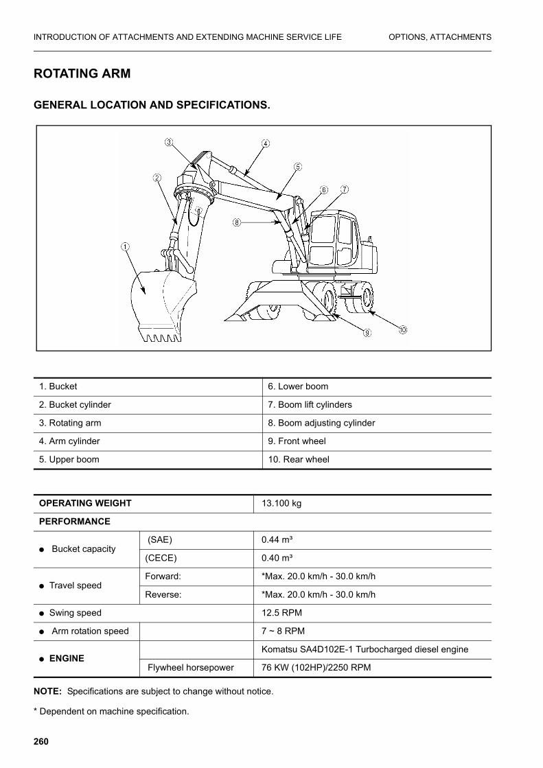
INTRODUCTION OF ATTACHMENTS AND EXTENDING MACHINE SERVICE LIFE OPTIONS, ATTACHMENTS
ROTATING ARM
GENERAL LOCATION AND SPECIFICATIONS.
NOTE: Specifications are subject to change without notice.
* Dependent on machine specification.
1. Bucket 6. Lower boom
2. Bucket cylinder 7. Boom lift cylinders
3. Rotating arm 8. Boom adjusting cylinder
4. Arm cylinder 9. Front wheel
5. Upper boom 10. Rear wheel
OPERATING WEIGHT 13.100 kg
PERFORMANCE
� Bucket capacity (SAE) 0.44 m³
(CECE) 0.40 m³
� Travel speed Forward: *Max. 20.0 km/h - 30.0 km/h
Reverse: *Max. 20.0 km/h - 30.0 km/h
� Swing speed 12.5 RPM
� Arm rotation speed 7 ~ 8 RPM
� ENGINE Komatsu SA4D102E-1 Turbocharged diesel engine
Flywheel horsepower 76 KW (102HP)/2250 RPM
260

OPTIONS, ATTACHMENTS INTRODUCTION OF ATTACHMENTS AND EXTENDING MACHINE SERVICE LIFE
GENERAL VIEW OF CONTROLS
LEFT WORK EQUIPMENT CONTROL LEVER (with auto-deceleration device)
WARNING
If any lever is operated when in the deceleration range, theengine speed will suddenly increase, so be careful whenoperating the levers.
This lever is used to operate the arm and upper structure.
1. Control lever pad safety lock 4. Knob button
2. Left work equipment control lever. 5. Indicators
3. Right work equipment control lever 6. Two piece boom pedal
AM089560A
Arm operation Swing operation
(A) Arm OUT (C) Swing to right
(B) Arm IN (D) Swing to left
N (Neutral)
261
INTRODUCTION OF ATTACHMENTS AND EXTENDING MACHINE SERVICE LIFE OPTIONS, ATTACHMENTS
When the lever in this position, the upper structure and the armwill be retained in the position in which they stop.
RIGHT WORK EQUIPMENT CONTROL LEVER (with auto-deceleration device)
WARNING
If an lever is operated when in the deceleration range, theengine speed will suddenly increase, so be careful whenoperating the levers.
This lever is used to operate the boom and bucket.
When the lever in this position, the boom and the bucket will beretained in the position in which they stop.
For levers (2), (3) and (4), the engine speed changes as followsbecause of the auto-deceleration mechanism.
� When the travel lever and work equipment control levers areat neutral, even if the fuel control dial is above the mid-rangeposition, the engine speed will drop to a mid-range speed. Ifany of the levers are operated, the engine speed will rise tothe speed set by the fuel control dial.
� If all control levers are set to neutral, the engine speed willdrop by approx. 100 rpm, and after approx. 4 seconds, theengine speed will drop to the deceleration speed (approx.1400 rpm).
ARM ROTATION CONTROL
The switches on the front of the right control levers control armrotation.
(1) Press the left button to rotate the arm anticlockwise facing theground.
(2) Press the right button to rotate the arm clockwise facing theground.
When neither switch is pressed the arm is stopped and held inposition.
AM089570A
Boom operation Bucket operation
(1) RAISE (3) DUMP
(2) LOWER (4) CURL
N (Neutral)
262

OPTIONS, ATTACHMENTS INTRODUCTION OF ATTACHMENTS AND EXTENDING MACHINE SERVICE LIFE
UPPER BOOM CONTROL PEDAL
This is used to operate the upper boom.
NEUTRAL: The upper boom is stopped and held in the sameposition.
CAUTION
Do not rest your food on the pedal unless using the pedal.
PEDAL LOCK FOR BOOM ADJUST
1. With the pedal in the neutral position screw in the pin to lockthe pedal.
2. Screw out the pin to unlock the pedal.
CAUTION
When the machine is stopped, when leaving the machine or when carrying out maintenance, always lock the boom adjustand arm rotation pedal.
EXCAVATOR’S WORK
In addition to the following, it is possible to further increase therange of applications by using various attachments.
BACK HOE WORK
A back hoe is suitable for excavation at a position lower themachine.It is possible to effectively move the arm through 30° inthe direction towards the machine and 45° in the direction awayfrom the machine, making for efficient work.
SHOVEL WORK
A shovel is suitable for excavating at a position higher than themachine.
LOADING WORK
About half of the time spent during excavating and loading work istaken up by swinging. Maximum work efficiency can be attainedby carrying out work is such a way that the swinging angle is keptas small as possible in accordance with the terrain.
(1)RAISE: Pedal pushed forward
(2) LOWER: Pedal pushed back
263

INTRODUCTION OF ATTACHMENTS AND EXTENDING MACHINE SERVICE LIFE OPTIONS, ATTACHMENTS
SPECIAL OPERATIONS
The rotating arm and 2-piece boom facilitate the following specialoperations.
PIT EXCAVATION FOR FOUNDATIONS OF BUILDINGS
Shafts with vertical walls can be excavated in all directions andsoil can be removed from around sheet piles.
SIDE DITCHING
The direction of the bucket teeth can be altered to facilitate theexcavation of parallel sided ditches.
OPERATION ON SLOPES
Vertical ditches can be dug on sloping surfaces.
DITCH DIGGING
Combination of rotating arm and upper boom make possible theprecise digging of offset ditch.
STATIONARY DIGGING
The excavation of trenches for main and branch water supply anddrainage pipes can be done without changing the machines posi-tion.
LIFTING SPOIL
The rotating arm enables working from all directions. Even if thereis a structure between the excavator and the bucket the work canbe done without hitting it.
BOX DIGGING
Perfect corners can be dug without having to change position ofexcavators.
SCRAPING
With bucket reversed the excavator can scrape faces upward.
REPLACEMENT OF BUCKET
Stop the machine on a firm, flat surface. When performing workwith another person, make clear signals to each other and workcarefully for safety’s sake.
1. Select a flat surface and stabilize the bucket.
2. After removing the stop bolt and nut for each pin, extract pinsA and B.
� After removing the pins, make sure that they do not becomecontaminated with sand or mud and that the seals of bushingon both sides do not become damaged.
AM090950A
Bucket cylinder
Arm
Link
264

OPTIONS, ATTACHMENTS INTRODUCTION OF ATTACHMENTS AND EXTENDING MACHINE SERVICE LIFE
CAUTION
Bucket size & bucket weightDo not fit a bucket larger than those listed overleaf for com-bination of undercarriage attachments, material to be exca-vated. Fitting of lager bucket will cause machine to tip over.
3. Couple the arm to hole (1), then connect the link to hole (2)
4. After mounting the stop bolt and nut for each pin, applygrease toeach pin.c.
265

INTRODUCTION OF ATTACHMENTS AND EXTENDING MACHINE SERVICE LIFE OPTIONS, ATTACHMENTS
HANDLING THE TRAPEZOIDAL BUCKET (If equipped)
This bucket is used in sloped ditch digging work.
The three different ditch inclination can be obtained by changingthe angle of the attached plate.
The angles available are 45°, 40° and 38°.
Shape of ditch by 45° bucket
Shape of ditch 40° bucket
45° ditch hole45°, 40°, 38°ditch hole
40° ditch hole
38° ditch hole38°, 40° ditch hole
266

OPTIONS, ATTACHMENTS INTRODUCTION OF ATTACHMENTS AND EXTENDING MACHINE SERVICE LIFE
Shape of ditch 38° bucket
How to perform excavation
Operate the boom, the arm and the bucket to make the line A ofthe side-plate of the bucket vertical.
To check this position guide plate B is installed beside the bucketpins.
Hold this plate horizontal when digging.
TRAVELLING POSTURE
Before starting to travel, be sure to pull in and lock the outriggers,and or raise the dozer blade.
Before travelling on public roads, the work equipment should bepositioned as follows:
1. Remove the bucket or attachment (refer to section see“REPLACEMENT OF BUCKET” on page 264.)
2. Position the upper structure so that it is facing the front of theundercarriage (the oscillation lock cylinders can be seen) andinsert the swing lock pin.
3. Fit link plate and spacers (Fig. 1)
267

INTRODUCTION OF ATTACHMENTS AND EXTENDING MACHINE SERVICE LIFE OPTIONS, ATTACHMENTS
4. Fully retract the bucket cylinder.
5. Align arrows & on swing circle. (Fig. 2)
6. Retract the arm cylinder approximately half-way. (Fig. 2)
7. Fully retract first and second boom cylinders.
8. Carefully lower the arm down onto the undercarriage. (Fig. 3)
9. Disable the work equipment levers by disengaging ppc lockswitch.
10. Screw in the lock pin on the Boom Adjust and Arm Rotatepedals.
11. Close manual lock valves.
1) For the bucket cylinder, located on the arm.
2) For the arm cylinder, located on the first boom.
After setting the machine in the travel posture, confirm that itsheight is below 4 m and that the distance between the centre ofthe steering wheel and the front of the work equipment is lessthan 3.5 m. Before moving off, lock all machine cover and toolboxdoors to prevent accidents.
MAINTENANCE REQUIREMENT
The following maintenance should be carried out in addition tothat in the PW130ES-6K Operation & Maintenance Manual.
NO ITEM SERVICE PAGE
EVERY 100 HOURS SERVICE
1 Arm rotation machinery case Check and supply page 269
EVERY 250 HOURS SERVICE
2 Arm rotation circle Lubricate 1 point page 269
EVERY 500 HOURS SERVICE
3 Arm rotation machinery case Check and supply page 270
EVERY 1000 HOURS SERVICE
4 Arm rotation machinery case Change oil page 270
268

OPTIONS, ATTACHMENTS INTRODUCTION OF ATTACHMENTS AND EXTENDING MACHINE SERVICE LIFE
EVERY 100 HOURS SERVICE
1. Arm rotation machinery case
1. Set the arm horizontal.
2. Remove plug (1)and check whether final drive case is filledwith oil to lower edge of plughole. If oil level is below thispoint, refill with SAE 90 gear oil through plug hole.(see“EVERY 1000 HOURS SERVICE” on page 270.)
� Tightening torque: 56 kgm
� The type of lubricant used depends on the ambient tempera-ture.
Select according to the table see “USE FUEL, COOLANTAND LUBRICANTS ACCORDING TO AMBIENT TEMPER-ATURE” on page 173.
EVERY 250 HOURS SERVICE
2. Arm rotation circle
LUBRICATING
Apply grease to the grease fittings shown by the arrows (3points).
269

INTRODUCTION OF ATTACHMENTS AND EXTENDING MACHINE SERVICE LIFE OPTIONS, ATTACHMENTS
EVERY 500 HOURS SERVICE
Maintenance for every 100 and 250 hours service should be carried out at the same time.
3. ARM ROTATION MACHINERY CASE
1. Disconnect hoses(1), (2) and (3) from the swing motor.
2. Plug the ends of the hoses and the ports in the motor.
3. Remove 12 bolts (4) from the swing motor and lift off.
4. Refill the grease bath with grease.
5. Replace the swing motor an and tighten the 12 bolts(Apply liquid gasket LG-6 to the mating faces and bolt holes).
6. Reconnect the hoses (1), (2) and (3) to the swing motor.
EVERY 1000 HOURS SERVICE
Maintenance for every 250 and 500 hours service should be carried out at the same time.
4. ARM ROTATION MACHINERY CASE
1. Remove plug (1), drain the oil.
2. Add 1.6 liters of SAE 90 Gear Oil through the plug hole.
3. After adding the oil, check that it is at the specified level(Refer to See "EVERY 100 HOURS SERVICE").
4. Replace the plug and retighten.
* Tightening torque: 56 kgm
270