PW Underwood Installation - Pro Warm · 2 support 01268 567019 Thank you for investing in our...
16
INSTALLATION MANUAL INSTALLATION MANUAL Ideal for most wood/ laminate floors Easy to install Fully compliant to latest regulations CE approved Suitable for most wooden/laminate floors (always check with floor manufacturer) LIFETIME LIFETIME WARRANTY
Transcript of PW Underwood Installation - Pro Warm · 2 support 01268 567019 Thank you for investing in our...

INST
ALL
ATIO
N M
AN
UA
L
INSTALLATION MANUAL
Ideal for most wood/laminate fl oors
Easy to install
Fully compliant tolatest regulations
CE approved
Suitable for mostwooden/laminate fl oors
(always check with fl oor manufacturer)
LIFETIMELIFETIMEWARRANTY

2support 01268 567019
Thank you for investing in our industryleading ProWarm™ underwood fl oor heating system
THIS INSTRUCTION MANUAL MUST BE READ ENTIRELY BEFORE COMMENCING ANY INSTALLATIONThis instruction manual contains important information regarding the safe installation and operation
of your heating mat/s.
These installation instructions are not intended to replace or supersede the installation instructions
provided by the manufacturers of your laminate/engineered/wooden fl oor but to supplement them.
Both sets of installation instructions should be complied with, (always check with the fl oor
manufacturer if you are in any doubt that our heating mat/s are suitable).
Our mats are extremely strong but care must be taken when installing them, please follow the step
by step installation guide to ensure a carefree installation.
leading ProWarm™ underwood floor heating systemThank you for investing in our industry
LIFETIMELIFETIMEWARRANTY

3www.prowarm.com
Product specifi cations and details 4
Important information 5
Controlling your system 6
Professional electrical installation 6
Contents of heating kit and items required for system installation 7
Testing 7
Installation instructions 8-13
Warranty 14-15
CONTENTS
CE approved systemsOur heating cables are CE approved, certifi ed and manufactured to the highest standards using state of the art Tefl on coated cables. All our cables are designed to be 17th Edition Part P compliant and the instructions we supply with them include as much information as possible to ensure that all installations comply with them (please contact us if you are in any doubt).
4support 01268 567019
Prod
uct s
peci
fi cat
ions
and
det
ails
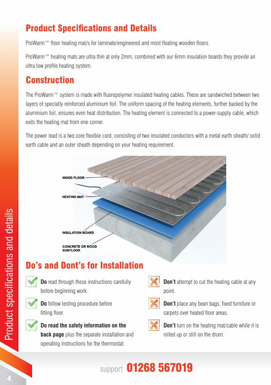
Product Specifi cations and Details
ProWarm™ fl oor heating mat/s for laminate/engineered and most fl oating wooden fl oors.
ProWarm™ heating mats are ultra thin at only 2mm, combined with our 6mm insulation boards they provide an
ultra low profi le heating system.
Construction
The ProWarm™ system is made with fl uoropolymer insulated heating cables. These are sandwiched between two
layers of specially reinforced aluminium foil. The uniform spacing of the heating elements, further backed by the
aluminium foil, ensures even heat distribution. The heating element is connected to a power-supply cable, which
exits the heating mat from one corner.
The power lead is a two core fl exible cord, consisting of two insulated conductors with a metal earth sheath/ solid
earth cable and an outer sheath depending on your heating requirement.
Do read through these instructions carefully
before beginning work.
Do follow testing procedure before
fi tting fl oor.
Do read the safety information on the
back page plus the separate installation and
operating instructions for the thermostat.
Don’t attempt to cut the heating cable at any
point.
Don’t place any bean bags, fi xed furniture or
carpets over heated fl oor areas.
Don’t turn on the heating mat/cable while it is
rolled up or still on the drum.
Do’s and Dont’s for Installation
5www.prowarm.com
Important Information: ■ ProWarm™ aluminium heating mat/s are designed for installation directly underneath engineered wood
or laminate fl oors, (Suitable ProWarm™ insulation MUST BE USED).
■ Aluminium heating mat/s are not designed for installation under ceramic tile, natural stone or similar
hard fl oor coverings; and MUST NOT be installed under nailed hardwood fl ooring. (please confi rm
suitability with us if you are in any doubt).
Contact us on [email protected] for more information.
■ COMPATIBLE WOOD LAMINATES & ENGINEERED BOARDS.Most modern wood laminate fl oors are compatible with our system, but fl oors that have metallic strips as part of their locking systems are NOT compatible as these metallic strips may damage the aluminium heating
mat/s. Also laminates that have an insulation pad already attached to the laminate are NOT compatible.
■ Check with your fl ooring supplier as to suitability for use with underfl oor heating. Max fl oor temp is generally 27°C. We do not recommend using wood fl oors thicker than 18mm, the system may still work but could cause problems over time including reduced effi ciency.
■ We want your installation to be trouble-free. If you are confronted with a problem you cannot solve, please do not hesitate to contact us on: 01268 567019
■ Aluminium heating mat/s MUST be connected to the electrical system through an RCD protected circuit and suitably rated fuse/MCB. Ensure that the circuits that supply power to your mats are RCD protected, or, if possible, a dedicated RCD is incorporated in each circuit supplying power to your mats.
This requirement is critical to the safe operation of the aluminium heating mat/s.
■ Aluminium heating mat/s MUST NOT be installed under cabinets or other fi ttings or furniture that will be permanently installed and attached to the fl oor. Built in cabinets and other furniture with solid bases must not be placed over the mats. Rugs and bean bags or any item which has a tog value of more than 2.5 should never
be placed on top of the fl oor as they can cause thermal blocking, and in extreme cases may lead to the cable
overheating causing a possible fi re hazard.
■ Aluminium heating mat/s MUST NOT be installed on top of other in-fl oor radiant heating systems (for example hydronic or in-screed systems) UNLESS the other system is permanently disconnected in such a way that it cannot be inadvertently switched on while the aluminium heating mat/s are also in use.
■ Similarly, aluminium heating mat/s MUST NOT be installed on fl oors where radiant ceiling heating mats are used in the room directly below where the aluminium heating mat/s are installed.
■ Aluminium heating mat/s MUST NOT be installed in thinset cement, or in direct contact with acement or concrete sub-fl oor or slab. There must always be a ProWarm™ approved insulation beneath the aluminium heating mat/s.
Impo
rtan
t inf
orm
atio
n

6support 01268 567019
Cont
rollin
g Yo
ur S
yste
m /
Prof
essi
onal
Ele
ctric
al In
stal
latio
nControlling Your System:
ProWarm™ heating systems can be controlled using any of our programmable thermostats using a fl oor
sensoring probe.
All thermostats are supplied with a fl oor sensor that allows you to set your heater to the exact temperature
you desire.
Our sophisticated units also allow you to set the time your heating turns on - for example one may choose to
have a warm bedroom fl oor fi rst thing in the morning upon waking, the fl oor does not need to remain warm during
the day, but can be programmed to come on again for a few hours around bedtime.
Most wood laminate manufacturers specify that their fl oors should not be subjected to temperatures in excess
of 28°C. The only reliable way to achieve this is to install a temperature sensor In the fl oor directly under the
aluminium heating mat/s, placed under the wood or laminate. Check with your laminate/engineered wood
manufacturer to see what their recommendations are for installing electric radiant heating under their fl oors.
Professional Electrical Installation:
Caution: Due to the new requirements of the Part P Regulations, only a qualifi ed person who is familiar with
the construction and operation of the apparatus and the hazards involved shall make the fi nal connections to the
electricity supply and test the installation.
The installation of electrical systems present risk of fi re and electrical shock which can result in personal injury.
Caution should always be taken to guard against each such risk. Only a qualifi ed electrician should connect and
test (as per the Commissioning Record Form) the aluminium heating mat/s to the thermostat and / or to the
electrical supply circuit.
All such connections MUST be in accordance with BS7671 17th Edition Part P wiring regulations.
Note: When installing thermostats in bathrooms they should always be located
outside the room and use the fl oor probe supplied, always check with a qualifi ed
electrician that all electrics are in safe and suitable zones.
IMPORTANT
7www.prowarm.com
Cont
ents
of h
eatin
g ki
t & it
ems
for s
yste
m in
stal
latio
n / T
estin
g
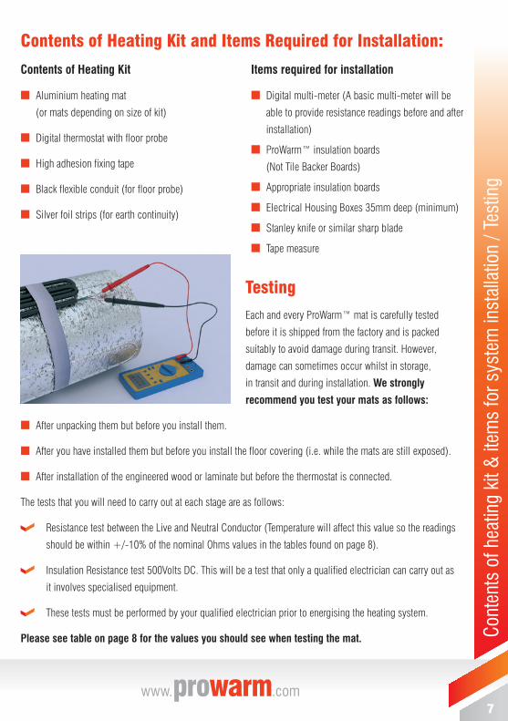
Testing
Each and every ProWarm™ mat is carefully tested
before it is shipped from the factory and is packed
suitably to avoid damage during transit. However,
damage can sometimes occur whilst in storage,
in transit and during installation. We strongly
recommend you test your mats as follows:
■ After unpacking them but before you install them.
■ After you have installed them but before you install the fl oor covering (i.e. while the mats are still exposed).
■ After installation of the engineered wood or laminate but before the thermostat is connected.
The tests that you will need to carry out at each stage are as follows:
Resistance test between the Live and Neutral Conductor (Temperature will affect this value so the readings
should be within +/-10% of the nominal Ohms values in the tables found on page 8).
Insulation Resistance test 500Volts DC. This will be a test that only a qualifi ed electrician can carry out as
it involves specialised equipment.
These tests must be performed by your qualifi ed electrician prior to energising the heating system.
Please see table on page 8 for the values you should see when testing the mat.
Contents of Heating Kit and Items Required for Installation:
Contents of Heating Kit
■ Aluminium heating mat
(or mats depending on size of kit)
■ Digital thermostat with fl oor probe
■ High adhesion fi xing tape
■ Black fl exible conduit (for fl oor probe)
■ Silver foil strips (for earth continuity)
Items required for installation
■ Digital multi-meter (A basic multi-meter will be
able to provide resistance readings before and after
installation)
■ ProWarm™ insulation boards
(Not Tile Backer Boards)
■ Appropriate insulation boards
■ Electrical Housing Boxes 35mm deep (minimum)
■ Stanley knife or similar sharp blade
■ Tape measure
8support 01268 567019
Inst
alla
tion
inst
ruct
ions
STE
P 1
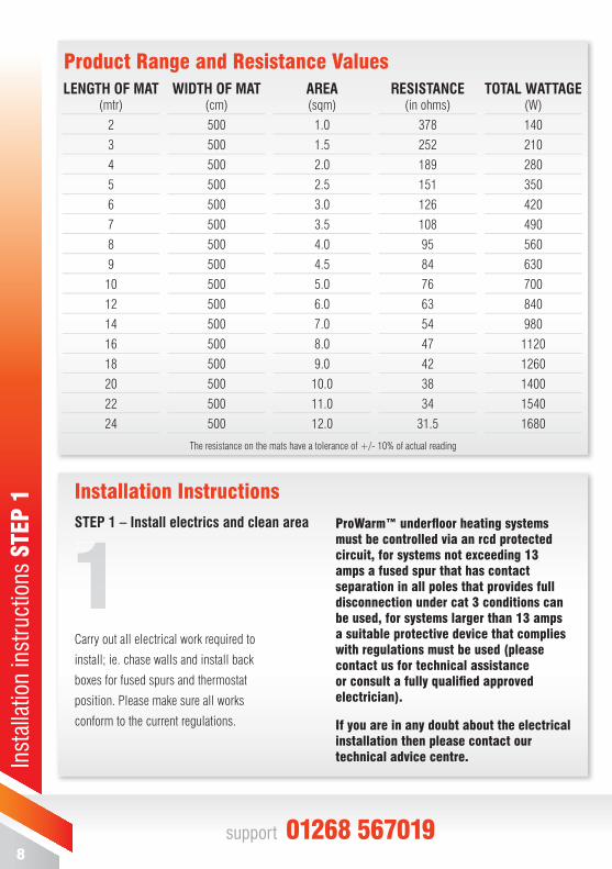
Product Range and Resistance Values
Installation InstructionsSTEP 1 – Install electrics and clean area
LENGTH OF MAT (mtr)
2
3
4
5
6
7
8
9
10
12
14
16
18
20
22
24
WIDTH OF MAT (cm)
500
500
500
500
500
500
500
500
500
500
500
500
500
500
500
500
AREA(sqm)
1.0
1.5
2.0
2.5
3.0
3.5
4.0
4.5
5.0
6.0
7.0
8.0
9.0
10.0
11.0
12.0
RESISTANCE(in ohms)
378
252
189
151
126
108
95
84
76
63
54
47
42
38
34
31.5
TOTAL WATTAGE(W)
140
210
280
350
420
490
560
630
700
840
980
1120
1260
1400
1540
1680
Carry out all electrical work required to
install; ie. chase walls and install back
boxes for fused spurs and thermostat
position. Please make sure all works
conform to the current regulations.
The resistance on the mats have a tolerance of +/- 10% of actual reading
ProWarm™ underfl oor heating systems must be controlled via an rcd protected circuit, for systems not exceeding 13 amps a fused spur that has contact separation in all poles that provides full disconnection under cat 3 conditions can be used, for systems larger than 13 amps a suitable protective device that complies with regulations must be used (please contact us for technical assistance or consult a fully qualifi ed approved electrician).
If you are in any doubt about the electrical installation then please contact our technical advice centre.
9www.prowarm.com
Inst
alla
tion
inst
ruct
ions
STE
P 2
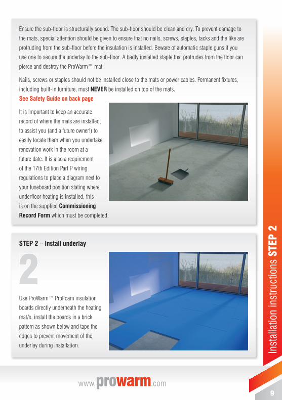
STEP 2 – Install underlay
Use ProWarm™ ProFoam insulation
boards directly underneath the heating
mat/s, install the boards in a brick
pattern as shown below and tape the
edges to prevent movement of the
underlay during installation.
Ensure the sub-fl oor is structurally sound. The sub-fl oor should be clean and dry. To prevent damage to
the mats, special attention should be given to ensure that no nails, screws, staples, tacks and the like are
protruding from the sub-fl oor before the insulation is installed. Beware of automatic staple guns if you
use one to secure the underlay to the sub-fl oor. A badly installed staple that protrudes from the fl oor can
pierce and destroy the ProWarm™ mat.
Nails, screws or staples should not be installed close to the mats or power cables. Permanent fi xtures,
including built-in furniture, must NEVER be installed on top of the mats.
See Safety Guide on back page
It is important to keep an accurate
record of where the mats are installed,
to assist you (and a future owner!) to
easily locate them when you undertake
renovation work in the room at a
future date. It is also a requirement
of the 17th Edition Part P wiring
regulations to place a diagram next to
your fuseboard position stating where
underfl oor heating is installed, this
is on the supplied Commissioning
Record Form which must be completed.
10support 01268 567019
Inst
alla
tion
inst
ruct
ions
STE
P 3
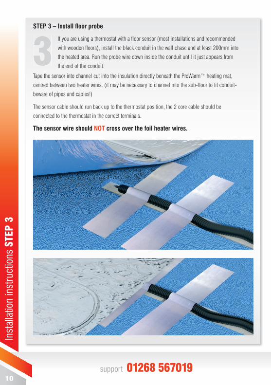
STEP 3 – Install fl oor probe
If you are using a thermostat with a fl oor sensor (most installations and recommended
with wooden fl oors), install the black conduit in the wall chase and at least 200mm into
the heated area. Run the probe wire down inside the conduit until it just appears from
the end of the conduit.
Tape the sensor into channel cut into the insulation directly beneath the ProWarm™ heating mat,
centred between two heater wires. (it may be necessary to channel into the sub-fl oor to fi t conduit-
beware of pipes and cables!)
The sensor cable should run back up to the thermostat position, the 2 core cable should be
connected to the thermostat in the correct terminals.
The sensor wire should NOT cross over the foil heater wires.
11www.prowarm.com
Inst
alla
tion
inst
ruct
ions
STE
P 4
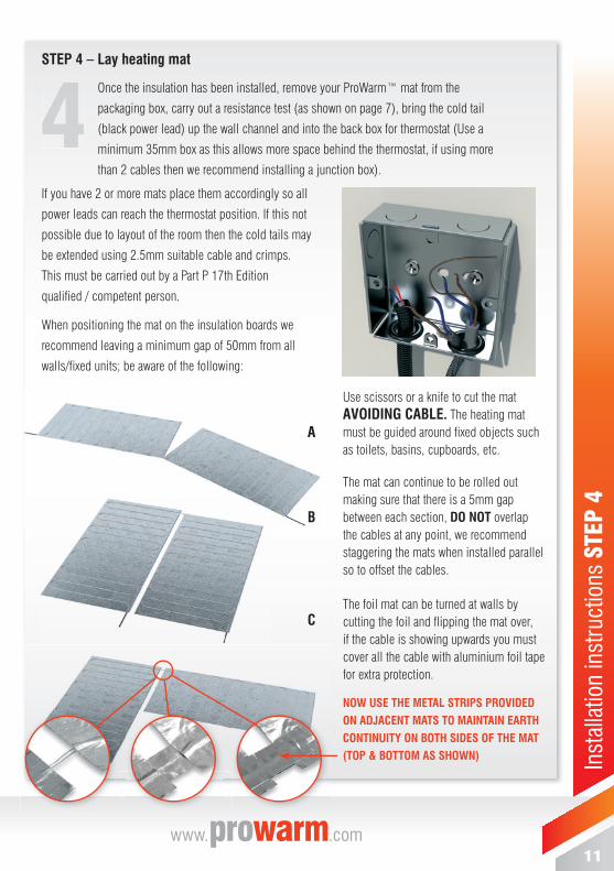
STEP 4 – Lay heating mat
Once the insulation has been installed, remove your ProWarm™ mat from the
packaging box, carry out a resistance test (as shown on page 7), bring the cold tail
(black power lead) up the wall channel and into the back box for thermostat (Use a
minimum 35mm box as this allows more space behind the thermostat, if using more
than 2 cables then we recommend installing a junction box).
If you have 2 or more mats place them accordingly so all
power leads can reach the thermostat position. If this not
possible due to layout of the room then the cold tails may
be extended using 2.5mm suitable cable and crimps.
This must be carried out by a Part P 17th Edition
qualifi ed / competent person.
When positioning the mat on the insulation boards we
recommend leaving a minimum gap of 50mm from all
walls/fi xed units; be aware of the following:
Use scissors or a knife to cut the mat AVOIDING CABLE. The heating mat must be guided around fi xed objects such as toilets, basins, cupboards, etc.
The mat can continue to be rolled out making sure that there is a 5mm gap between each section, DO NOT overlap the cables at any point, we recommend staggering the mats when installed parallel so to offset the cables.
The foil mat can be turned at walls by cutting the foil and fl ipping the mat over,if the cable is showing upwards you must cover all the cable with aluminium foil tape for extra protection.
NOW USE THE METAL STRIPS PROVIDED ON ADJACENT MATS TO MAINTAIN EARTH CONTINUITY ON BOTH SIDES OF THE MAT(TOP & BOTTOM AS SHOWN)
A
B
C
12support 01268 567019
Inst
alla
tion
inst
ruct
ions
STE
P 4
cont
’d
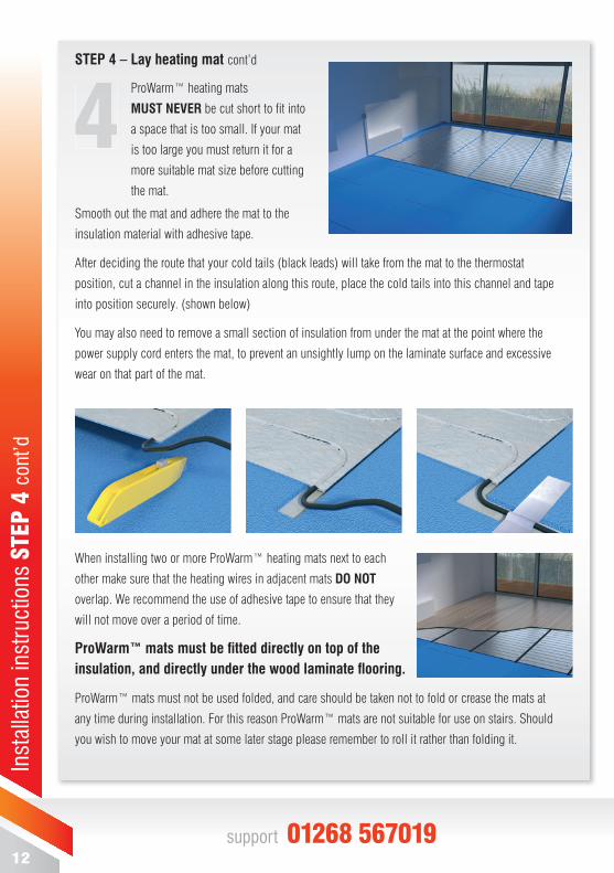
STEP 4 – Lay heating mat cont’d
ProWarm™ heating mats
MUST NEVER be cut short to fi t into
a space that is too small. If your mat
is too large you must return it for a
more suitable mat size before cutting
the mat.
Smooth out the mat and adhere the mat to the
insulation material with adhesive tape.
After deciding the route that your cold tails (black leads) will take from the mat to the thermostat
position, cut a channel in the insulation along this route, place the cold tails into this channel and tape
into position securely. (shown below)
You may also need to remove a small section of insulation from under the mat at the point where the
power supply cord enters the mat, to prevent an unsightly lump on the laminate surface and excessive
wear on that part of the mat.
When installing two or more ProWarm™ heating mats next to each
other make sure that the heating wires in adjacent mats DO NOT
overlap. We recommend the use of adhesive tape to ensure that they
will not move over a period of time.
ProWarm™ mats must be fi tted directly on top of the insulation, and directly under the wood laminate fl ooring.
ProWarm™ mats must not be used folded, and care should be taken not to fold or crease the mats at
any time during installation. For this reason ProWarm™ mats are not suitable for use on stairs. Should
you wish to move your mat at some later stage please remember to roll it rather than folding it.
13www.prowarm.com
Inst
alla
tion
inst
ruct
ions
STE
P 5
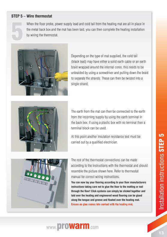
STEP 5 – Wire thermostat
When the fl oor probe, power supply lead and cold tail from the heating mat are all in place in
the metal back box and the mat has been laid, you can then complete the heating installation
by wiring the thermostat.
Depending on the type of mat supplied, the cold tail
(black lead) may have either a solid earth cable or an earth
braid wrapped around the internal cores, this needs to be
unbraided by using a screwdriver and pulling down the braid
to separate the strands. These can then be twisted into a
single strand.
The earth from the mat can then be connected to the earth
from the incoming supply by using the earth terminal in
the back box. If using a plastic box with no terminal then a
terminal block can be used.
At this point another insulation resistance test must be
carried out by a qualifi ed electrician.
The rest of the thermostat connections can be made
according to the instructions with the thermostat and should
resemble the picture shown here. Refer to thermostat
manual for correct wiring instructions.You can now lay your fl ooring according to your fl oor manufacturers
instructions taking care not to glue the fl oor to the matting or nail
through the fl oor! Click systems can simply be clicked together and
laid over the heating and engineered wood fl ooring can be glued
along the tongue and groove and fl oated over the heating mat.
Ensure no glue comes into contact with the heating mat.

14
Life
time
War
rant
y
LIFETIMELIFETIMEWARRANTYLIFETITI
Need Help installing your underfl oor heating?
We can recommend approved electrical contractors who can install your heating from start to fi nish
Call us on 01268 567019 and we will be happy to help.
ProWarm™ fl oor heating mats come with a full lifetime warranty.
The warranty does not cover installations made by unauthorized persons or faults caused by incorrect design by others / misuse / damage caused by others / damage in transit / incorrect installation and any other subsequent damage that may occur. Replacement will be fully chargeable if the damage is because of any of the above reasons.
Please visit website for full terms and conditions.www.ProWarm.com

15
Life
time
War
rant
y
CableSafe™ Guarantee
ProWarm™ is the only company that offers you a no quibble exchange on a damaged cable!
If you damage your heating cable during installation then on receipt of the damaged cable/mat we will send you a new one of the same size free of charge. Only one cable/mat per Invoice.
This amazing free peace-of-mind insurance is only offered by ProWarm™ - No waiting for a repair engineer to come out and no
more expensive mistakes - as soon as we receive yourreturned cable/mat we will send you a new one on next
working day delivery.
Please visit website for full terms and conditions.www.ProWarm.comWarm.com
GUA R A N TEE
CABLESAFEGUUUAAAAA RRR AAA NNN TTTEE
GGGUUUEEEEEE
s.
www.prowarm.com

Unit 12, Carnival Park, Carnival Way, Basildon, Essex, SS14 3WN
T: 01268 567019www. .com
SAFETY GUIDELINES
IMPORTANT
This installation manual has been designed for your safety. For a successful installation please make sure you have understood the guidelines and adhered to all the instructions
Flat bottomed furniture MUST NOT BE placed over areas where the heating mat/cable is installed as this can restrict airfl ow to the fl oor, causing thermal
blocking, and in extreme cases may lead to the
cable overheating causing a possible fi re hazard. This also includes rugs, bean bags, or any item which has a tog value greater than 2.5.
The supplied Commissioning MUST BE completed, including the fl oor plan sketch, to indicate heated areas, which must be permanently fi xed in or near the distribution/fuse board as required by the 17th Edition BS7671 amendment 3
FLAT BASED FURNITURE
MATTRESSES
BEAN BAGS
ANIMAL BEDS
RUGS