PVS 305SA User's Manual -...
56
PVS 305SA PoleVault ® Switcher 68-1576-01 Rev. A 02 10
Transcript of PVS 305SA User's Manual -...

PVS 305SAPoleVault® Switcher
68-1576-01 Rev. A
02 10
This symbol is intended to alert the user of important operating and maintenance (servicing) instructions in the literature provided with the equipment.
This symbol is intended to alert the user of the presence of uninsulated dangerous voltage within the product’s enclosure that may present a risk of electric shock.
CautionRead Instructions • Read and understand all safety and operating instructions before using the equipment.
Retain Instructions • The safety instructions should be kept for future reference.
Follow Warnings • Follow all warnings and instructions marked on the equipment or in the user information.
Avoid Attachments • Do not use tools or attachments that are not recommended by the equipment manufacturer because they may be hazardous.
WarningPower sources • This equipment should be operated only from the power source indicated on the product. This
equipment is intended to be used with a main power system with a grounded (neutral) conductor. The third (grounding) pin is a safety feature, do not attempt to bypass or disable it.
Power disconnection • To remove power from the equipment safely, remove all power cords from the rear of the equipment, or the desktop power module (if detachable), or from the power source receptacle (wall plug).
Power cord protection • Power cords should be routed so that they are not likely to be stepped on or pinched by items placed upon or against them.
Servicing • Refer all servicing to qualified service personnel. There are no user-serviceable parts inside. To prevent the risk of shock, do not attempt to service this equipment yourself because opening or removing covers may expose you to dangerous voltage or other hazards.
Slots and openings • If the equipment has slots or holes in the enclosure, these are provided to prevent overheating of sensitive components inside. These openings must never be blocked by other objects.
Lithium battery • There is a danger of explosion if battery is incorrectly replaced. Replace it only with the same or equivalent type recommended by the manufacturer. Dispose of used batteries according to the manufacturer’s instructions.
Ce symbole sert à avertir l’utilisateur que la documentation fournie avec le matériel contient des instructions importantes concernant l’exploitation et la maintenance (réparation).
Ce symbole sert à avertir l’utilisateur de la présence dans le boîtier de l’appareil de tensions dangereuses non isolées posant des risques d’électrocution.
AttentionLire les instructions• Prendre connaissance de toutes les consignes de sécurité et d’exploitation avant
d’utiliser le matériel.
Conserver les instructions• Ranger les consignes de sécurité afin de pouvoir les consulter à l’avenir.
Respecter les avertissements • Observer tous les avertissements et consignes marqués sur le matériel ou présentés dans la documentation utilisateur.
Eviter les pièces de fixation • Ne pas utiliser de pièces de fixation ni d’outils non recommandés par le fabricant du matériel car cela risquerait de poser certains dangers.
AvertissementAlimentations• Ne faire fonctionner ce matériel qu’avec la source d’alimentation indiquée sur l’appareil. Ce
matériel doit être utilisé avec une alimentation principale comportant un fil de terre (neutre). Le troisième contact (de mise à la terre) constitue un dispositif de sécurité : n’essayez pas de la contourner ni de la désactiver.
Déconnexion de l’alimentation• Pour mettre le matériel hors tension sans danger, déconnectez tous les cordons d’alimentation de l’arrière de l’appareil ou du module d’alimentation de bureau (s’il est amovible) ou encore de la prise secteur.
Protection du cordon d’alimentation • Acheminer les cordons d’alimentation de manière à ce que personne ne risque de marcher dessus et à ce qu’ils ne soient pas écrasés ou pincés par des objets.
Réparation-maintenance • Faire exécuter toutes les interventions de réparation-maintenance par un technicien qualifié. Aucun des éléments internes ne peut être réparé par l’utilisateur. Afin d’éviter tout danger d’électrocution, l’utilisateur ne doit pas essayer de procéder lui-même à ces opérations car l’ouverture ou le retrait des couvercles risquent de l’exposer à de hautes tensions et autres dangers.
Fentes et orifices • Si le boîtier de l’appareil comporte des fentes ou des orifices, ceux-ci servent à empêcher les composants internes sensibles de surchauffer. Ces ouvertures ne doivent jamais être bloquées par des objets.
Lithium Batterie • Il a danger d’explosion s’ll y a remplacment incorrect de la batterie. Remplacer uniquement avec une batterie du meme type ou d’un ype equivalent recommande par le constructeur. Mettre au reut les batteries usagees conformement aux instructions du fabricant.
Safety Instructions • English
Consignes de Sécurité • Français
Sicherheitsanleitungen • DeutschDieses Symbol soll dem Benutzer in der im Lieferumfang enthaltenen Dokumentation besonders wichtige Hinweise zur Bedienung und Wartung (Instandhaltung) geben.
Dieses Symbol soll den Benutzer darauf aufmerksam machen, daß im Inneren des Gehäuses dieses Produktes gefährliche Spannungen, die nicht isoliert sind und die einen elektrischen Schock verursachen können, herrschen.
AchtungLesen der Anleitungen • Bevor Sie das Gerät zum ersten Mal verwenden, sollten Sie alle Sicherheits-und
Bedienungsanleitungen genau durchlesen und verstehen.
Aufbewahren der Anleitungen • Die Hinweise zur elektrischen Sicherheit des Produktes sollten Sie aufbewahren, damit Sie im Bedarfsfall darauf zurückgreifen können.
Befolgen der Warnhinweise • Befolgen Sie alle Warnhinweise und Anleitungen auf dem Gerät oder in der Benutzerdokumentation.
Keine Zusatzgeräte • Verwenden Sie keine Werkzeuge oder Zusatzgeräte, die nicht ausdrücklich vom Hersteller empfohlen wurden, da diese eine Gefahrenquelle darstellen können.
VorsichtStromquellen • Dieses Gerät sollte nur über die auf dem Produkt angegebene Stromquelle betrieben werden.
Dieses Gerät wurde für eine Verwendung mit einer Hauptstromleitung mit einem geerdeten (neutralen) Leiter konzipiert. Der dritte Kontakt ist für einen Erdanschluß, und stellt eine Sicherheitsfunktion dar. Diese sollte nicht umgangen oder außer Betrieb gesetzt werden.
Stromunterbrechung • Um das Gerät auf sichere Weise vom Netz zu trennen, sollten Sie alle Netzkabel aus der Rückseite des Gerätes, aus der externen Stomversorgung (falls dies möglich ist) oder aus der Wandsteckdose ziehen.
Schutz des Netzkabels • Netzkabel sollten stets so verlegt werden, daß sie nicht im Weg liegen und niemand darauf treten kann oder Objekte darauf- oder unmittelbar dagegengestellt werden können.
Wartung • Alle Wartungsmaßnahmen sollten nur von qualifiziertem Servicepersonal durchgeführt werden. Die internen Komponenten des Gerätes sind wartungsfrei. Zur Vermeidung eines elektrischen Schocks versuchen Sie in keinem Fall, dieses Gerät selbst öffnen, da beim Entfernen der Abdeckungen die Gefahr eines elektrischen Schlags und/oder andere Gefahren bestehen.
Schlitze und Öffnungen • Wenn das Gerät Schlitze oder Löcher im Gehäuse aufweist, dienen diese zur Vermeidung einer Überhitzung der empfindlichen Teile im Inneren. Diese Öffnungen dürfen niemals von anderen Objekten blockiert werden.
Litium-Batterie • Explosionsgefahr, falls die Batterie nicht richtig ersetzt wird. Ersetzen Sie verbrauchte Batterien nur durch den gleichen oder einen vergleichbaren Batterietyp, der auch vom Hersteller empfohlen wird. Entsorgen Sie verbrauchte Batterien bitte gemäß den Herstelleranweisungen.
Este símbolo se utiliza para advertir al usuario sobre instrucciones importantes de operación y mantenimiento (o cambio de partes) que se desean destacar en el contenido de la documentación suministrada con los equipos.
Este símbolo se utiliza para advertir al usuario sobre la presencia de elementos con voltaje peligroso sin protección aislante, que puedan encontrarse dentro de la caja o alojamiento del producto, y que puedan representar riesgo de electrocución.
PrecaucionLeer las instrucciones • Leer y analizar todas las instrucciones de operación y seguridad, antes de usar el
equipo.
Conservar las instrucciones • Conservar las instrucciones de seguridad para futura consulta.
Obedecer las advertencias • Todas las advertencias e instrucciones marcadas en el equipo o en la documentación del usuario, deben ser obedecidas.
Evitar el uso de accesorios • No usar herramientas o accesorios que no sean especificamente recomendados por el fabricante, ya que podrian implicar riesgos.
AdvertenciaAlimentación eléctrica • Este equipo debe conectarse únicamente a la fuente/tipo de alimentación eléctrica
indicada en el mismo. La alimentación eléctrica de este equipo debe provenir de un sistema de distribución general con conductor neutro a tierra. La tercera pata (puesta a tierra) es una medida de seguridad, no puentearia ni eliminaria.
Desconexión de alimentación eléctrica • Para desconectar con seguridad la acometida de alimentación eléctrica al equipo, desenchufar todos los cables de alimentación en el panel trasero del equipo, o desenchufar el módulo de alimentación (si fuera independiente), o desenchufar el cable del receptáculo de la pared.
Protección del cables de alimentación • Los cables de alimentación eléctrica se deben instalar en lugares donde no sean pisados ni apretados por objetos que se puedan apoyar sobre ellos.
Reparaciones/mantenimiento • Solicitar siempre los servicios técnicos de personal calificado. En el interior no hay partes a las que el usuario deba acceder. Para evitar riesgo de electrocución, no intentar personalmente la reparación/mantenimiento de este equipo, ya que al abrir o extraer las tapas puede quedar expuesto a voltajes peligrosos u otros riesgos.
Ranuras y aberturas • Si el equipo posee ranuras o orificios en su caja/alojamiento, es para evitar el sobrecalientamiento de componentes internos sensibles. Estas aberturas nunca se deben obstruir con otros objetos.
Batería de litio • Existe riesgo de explosión si esta batería se coloca en la posición incorrecta. Cambiar esta batería únicamente con el mismo tipo (o su equivalente) recomendado por el fabricante. Desachar las baterías usadas siguiendo las instrucciones del fabricante.
Instrucciones de seguridad • Español
Precautions
安全须知 • 中文这个符号提示用户该设备用户手册中有重要的操作和维护说明。
这个符号警告用户该设备机壳内有暴露的危险电压,有触电危险。
注意阅读说明书 • 用户使用该设备前必须阅读并理解所有安全和使用说明。
保存说明书 • 用户应保存安全说明书以备将来使用。
遵守警告 • 用户应遵守产品和用户指南上的所有安全和操作说明。
避免追加 • 不要使用该产品厂商没有推荐的工具或追加设备,以避免危险。
警告电源 • 该设备只能使用产品上标明的电源。 设备必须使用有地线的供电系统供电。 第三条线
(地线)是安全设施,不能不用或跳过 。
拔掉电源 • 为安全地从设备拔掉电源,请拔掉所有设备后或桌面电源的电源线,或任何接到市电系统的电源线。
电源线保护 • 妥善布线, 避免被踩踏,或重物挤压。
维护 • 所有维修必须由认证的维修人员进行。 设备内部没有用户可以更换的零件。为避免出现触电危险不要自己试图打开设备盖子维修该设备。
通风孔 • 有些设备机壳上有通风槽或孔,它们是用来防止机内敏感元件过热。 不要用任何东西挡住通风孔。
锂电池 • 不正确的更换电池会有爆炸的危险。必须使用与厂家推荐的相同或相近型号的电池。按照生产厂的建议处理废弃电池。

FCC Class B NoticeThis equipment has been tested and found to comply with the limits for a Class B digital device, pursuant to part 15 of the FCC Rules. These limits are designed to provide reasonable protection against harmful interference in a residential installation. This equipment generates, uses and can radiate radio frequency energy and, if not installed and used in accordance with the instructions, may cause harmful interference to radio communications. However, there is no guarantee that the interference will not occur in a particular installation. If this equipment does cause harmful interference to radio or television reception, which can be determined by turning the equipment off and on, the user is encouraged to try to correct the interference by one or more of the following measures:
• Reorient or relocate the receiving antenna.• Increase the separation between the equipment and receiver.• Connect the equipment into an outlet on a circuit different from that to which the receiver is connected.• Consult the dealer or an experienced radio/TV technician for help.
N Thisunitwastestedwithshieldedcablesontheperipheraldevices.Shieldedcablesmustbeusedwiththeunittoensurecompliance.

iPVS 305SA Switcher • Table of Contents
Table of Contents
PREL
IMIN
ARY
PREL
IMIN
ARY
Chapter One • Introduction .......................................................................................................1-1
About this Manual .....................................................................................................................1-2
About the PVS 305SA ...............................................................................................................1-2TP cable advantages� .................................................................................................................1-2Features� ......................................................................................................................................1-3
Application Diagram ................................................................................................................1-4
Chapter Two • Installation ..........................................................................................................2-1
UL/Safety Requirements .........................................................................................................2-2Important s�afety ins�tructions� ..................................................................................................2-2
Mounting the Switcher ..........................................................................................................2-3Mounting directly onto the plate us�ing s�crews�. ...................................................................2-3Mounting onto the plate us�ing brackets�. .............................................................................2-4Wall mounting the PoleVault s�witcher ..................................................................................2-5
Rear Panel Features and Cabling ....................................................................................2-6A/V input connections� ..............................................................................................................2-6A/V output connections� ...........................................................................................................2-8VoiceLift connection (optional)� ..............................................................................................2-8Aux audio input ........................................................................................................................2-8Paging s�ens�or connector (optional)� .......................................................................................2-8DC Volume/Mute Control .........................................................................................................2-8Switcher control ........................................................................................................................2-9Speaker output ........................................................................................................................2-11Line out audio output ............................................................................................................2-11Power s�upply connector .........................................................................................................2-11
Labeling the A/V Inputs ........................................................................................................2-12Labeling and connecting the A/V input cables� ...................................................................2-12Labeling the PVT Decora® face plates� ..................................................................................2-13
Final Setup ....................................................................................................................................2-13
Chapter Three • Operation and Setup ...............................................................................3-1
Front Panel Features and Operation .............................................................................3-2Front panel operation ..............................................................................................................3-3Configuration ............................................................................................................................3-3
Resetting the Switcher ...........................................................................................................3-3
Executive Mode (Front Panel Security Lockout)� .....................................................3-4
Setting Up and Optimizing the Audio ...........................................................................3-4Steps� for optimizing the audio ...............................................................................................3-4Gain control ...............................................................................................................................3-5
Individual channel input s�ens�itivity control .......................................................................3-5Front panel input s�ens�itivity adjus�tment ...........................................................................3-5Amplifier level control .......................................................................................................3-6

ii PVS 305SA Switcher • Table of Contents
Table of Contents, cont’d
PREL
IMIN
ARY
PREL
IMIN
ARY
Bas�s�, treble, and loudnes�s� control ..........................................................................................3-6VoiceLift® level adjus�tment ......................................................................................................3-6Paging s�ens�itivity adjus�tment .................................................................................................3-6
Chapter Four • Serial Communication ..............................................................................4-1
RS-232 Programmer’s Guide ................................................................................................4-2Hos�t-to-PVS communications� ..................................................................................................4-2
PVS-initiated mes�s�ages� ........................................................................................................4-2Error res�pons�es� ....................................................................................................................4-3Us�ing the command/res�pons�e tables�..................................................................................4-3Symbol definitions� ...............................................................................................................4-3Factory defaults� ...................................................................................................................4-5
Command/res�pons�e table for SIS™ commands� ......................................................................4-6Command/res�pons�e table for SIS commands� (continued)� ..................................................4-8
Updating Firmware .................................................................................................................4-10
Chapter Five • Software Configuration ...........................................................................5-1
Configuring the Switcher ....................................................................................................5-2Ins�talling the MediaLink® Switcher Configuration program ..............................................5-2
From the DVD ......................................................................................................................5-2From the Web s�ite ...............................................................................................................5-2
Ins�talling the Global Configurator .........................................................................................5-3From the DVD ......................................................................................................................5-3
Appendix A • Reference Information ............................................................................... A-1
Specifications — PVS 305SA ............................................................................................... A-2
Part Numbers, Cables, and Accessories ....................................................................... A-5Included parts� ........................................................................................................................... A-5Cables� ......................................................................................................................................... A-5
Appendix B • Speaker Configuration ................................................................................B-2Terminating the s�peaker cable ................................................................................................B-2
Wiring Information ...................................................................................................................B-3Signal cables�...............................................................................................................................B-3Aux audio input cables� ...................................................................................................... B-3Line out audio cables�................................................................................................................B-3Switcher control cables� ............................................................................................................B-3Cabling the s�witcher .................................................................................................................B-4
Alltrademarksmentionedinthismanualarethepropertiesoftheirrespectiveowners.

PVS 305SA
1Chapter One
Introduction
About this� Manual
About the PVS 305SA
Application Diagram
PVS 305SA Switcher • Introduction1-2
Introduction
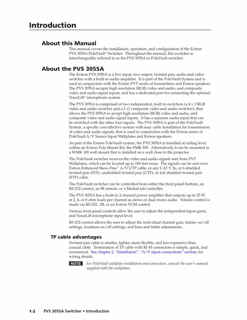
About this ManualThis manual covers the installation, operation, and configuration of the Extron PVS 305SA PoleVault® Switcher. Throughout the manual, this switcher is interchangeably referred to as the PVS 305SA or PoleVault switcher.
About the PVS 305SAThe Extron PVS 305SA is a five input, two output, twisted pair, audio and video switcher with a built-in audio amplifier. It is part of the PoleVault System and is used in conjunction with the Extron PVT series of transmitters and Extron speakers. The PVS 305SA accepts high resolution (RGB) video and audio, and composite video and audio signal inputs, and has a dedicated port for connecting the optional VoiceLift® microphone system.
The PVS 305SA is comprised of two independent, built in switchers (a 4 x 1 RGB video and audio switcher and a 2 x1 composite video and audio switcher), that allows the PVS 305SA to accept high resolution (RGB) video and audio, and composite video and audio signal inputs. It has a separate audio input that can be switched with the other four inputs. The PVS 305SA is part of the PoleVault System, a specific cost effective system with easy cable installation for transmission of video and audio signals, that is used in conjunction with the Extron series of PoleVault A/V Source Input Wallplates and Extron speakers.
As part of the Extron PoleVault system, the PVS 305SA is installed at ceiling level within an Extron Pole Mount Kit, the PMK 550. Alternatively it can be mounted in a WMK 100 wall mount that is installed on a wall close to the projector.
The PoleVault switcher receives the video and audio signals sent from PVT Wallplates, which can be located up to 100 feet away. The signals can be sent over Extron Enhanced Skew-Free™ A/V UTP cable, or any CAT 5, 5e, or 6 shielded twisted pair (STP), unsheilded twisted pair (UTP), or foil shielded twisted pair (FTP) cable.
The PoleVault switcher can be controlled from either the front panel buttons, anRS-232 control, an IR remote, or a MediaLink controller.
The PVS 305SA has a built-in 2-channel power amplifier that outputs up to 25 W at 2, 4, or 8 ohm loads per channel as stereo or dual mono audio. Volume control is made via RS-232 , IR, or an Extron VCM control.
Various front panel controls allow the user to adjust the independent input gains, and VoiceLift microphone input level.
RS-232 control allows the user to adjust the individual channel gain, limiter on/off settings, loudness on/off settings, and bass and treble adjustments.
TP cable advantagesTwisted pair cable is smaller, lighter, more flexible, and less expensive than coaxial cable. Termination of TP cable with RJ-45 connectors is simple, quick, and economical. See chapter 2, “Installation”, “A/V input connections” section, for wiring details.
N ForPoleVaultwallplateinstallationandconnection,consulttheuser’smanualsuppliedwiththewallplates.

1-3PVS 305SA Switcher • Introduction
FeaturesTwisted pair inputs — The PoleVault switcher accepts two independent, high
resolution RGB video and audio signals, and two configurable inputs for either composite video or high resolution RGB signals, and audio signals, transmitted on twisted pair cable from a source up to 100 ft away.
Video output — The PoleVault switcher can switch between four inputs (either four RGB or two RGB and two composite).
VoiceLift input — The PoleVault switcher can mix a mono line level audio input from the VoiceLift microphone system with the audio input from the video/audio source.
Amplified Audio output — The PoleVault switcher allows user selectable stereo or dual mono, 2/4/8 ohm audio outputs through the integrated audio amplifier.
Line Out output — The PoleVault switcher allows for the connection of a recording or listening device for audio output.
Paging System support — The PoleVault switcher allows for the connecting of a public address paging system sensor which when activated, mutes the PoleVault switcher’s program for the duration of the PA broadcast.
Executive Mode — To prevent unauthorized access the PoleVault switcher panel can be locked (executive mode) via the front panel or RS-232. An LED on the front panel indicates executive mode status.
Control and configuration — Firmware updates to the PVS 305SA can be made via a front panel config port. The PoleVault switcher can also be configured via RS-232 and controlled via the front panel, RS-232, or wired IR.
Other features include:
• User selectable switching of input and status indication LED
• Rear panel mounted captive screw connector for RS-232, MLC, or IR control
• Rear panel mounted captive screw connector for external volume control
• Energy efficient design offers Extron exclusive Auto Power Save and Standby modes designed to lower energy usage and reduce costs.

Introduction, cont’d
PVS 305SA Switcher • Introduction1-4
Application Diagram
PVS 305SA
POLEVAULT SWITCHER
INPUT SELECTION
1
2
PEAK
NORMALSIGNAL
CONFIG
3
4
5
AUX AUDIOAUDIO LEVEL ADJUST
PAGINGSENSOR
SENSITIVITY
VOICELIFT
MIC
PEAK
NORMALSIGNAL
INPUT
Ceiling Mounted Paging Speaker
Extron Priority Page Sensor(Optional Accessory)
FromPA System
ToPoleVault Switcher
ExtronPMK 550Easy Installation Pole Mount Kit
RS-232to Projector
RS-232 to Switcher
AssistiveListeningSystem
IREmitter
UTP Cable(CAT 5/5E/6)
ExtronPCM 340Projector DropCeiling Mount
Slotted Projector Mount Pole
ExtronUPB 25Universal ProjectorMounting Bracket
ExtronSPK 18 - 35'Cable
ExtronPVS 305SAPoleVault® Switcher
ExtronFF 120Flat Field Ceiling Speakers - 1 Pair
ExtronPVT RGB D PlusVGA & Audio InputWallplate
ExtronPVT CV DComposite Video& Audio InputWallplate
DVD/VCR Combo
PC
ExtronPVT CV DComposite Video& Audio InputWallplate
ExtronVoiceLift Microphoneand Charging Station(Optional Accessory)
ExtronVoiceLift® Receiver(Optional Accessory)
Camera
Computer w/Podcasting Software
ExtronPVT RGB DVGA & Audio Input Wallplate
Document Camera
COMPUTER IN
AUDIO IN Extron MLC 104 IP PlusMediaLink® Controller
CONFIG
DISPLAY
VOLUME
MLC 104 IP PLUS
ON
VCR
DVD
PC
OFF
1
2
3
4
L
SG
AUDIO IN
VIDEO IN
IR OUT
R
COMPUTER IN
AUDIOINAUDIOOUT
MONITOR OUT
SG
IR OUT
L
SG
AUDIO IN
VIDEO IN
IR OUT
R
Extron
PWR
CH
AR
GE
OFF
/MU
TE
/CH
GO
N
Extron
Extron
PWR
CH
AR
GE
OFF
/MU
TE
/CH
GO
N
TCP/IPNetwork
Figure 1-1 — PVS 305SA in a typical PoleVault system installation, with optional accessories

PVS 305SAPVS 305SA
2Chapter Two
Installation
UL/Safety Requirements�
Mounting the Switcher
Rear Panel Features� and Cabling
Speaker Configuration
Labeling the A/V Inputs�
Final Setup

PVS 305SA Switcher • Installation2-2
Installation
PREL
IMIN
ARY
UL/Safety RequirementsThe Underwriters Laboratories (UL) requirements listed below pertain to the safe installation and operation of this switcher.
Important safety instructions1. Read these instructions.
2. Keep these instructions.
3. Heed all warnings.
4. Follow all instructions.
5. Do not use this apparatus near water.
6. Clean only with a dry cloth.
7. Do not block any ventilation openings. Install in accordance with the manufacturer’s instructions.
8. Do not install near any heat sources such as radiators, heat registers, stoves, or other apparatus (including amplifiers) that produce heat.
9. Do not defeat the safety purpose of the polarized or grounding type plug. A polarized plug has two blades with one wider than the other. A grounding type plug has two blades and a third grounding prong. The wide blade or the third prong are provided for your safety. If the provided plug does not fit into your outlet, consult an electrician for replacement of the obsolete outlet.
10. Protect the power cord from being walked on or pinched particularly at plugs, convenience receptacles, and the point where they exit from the apparatus.
11. Only use attachments/accessories specified by the manufacturer.
12. Use only with the cart, stand, tripod, bracket, or table specified by the manufacturer or sold with the apparatus. When a cart is used, use caution when moving the cart/apparatus combination to avoid injury from tip-over.
13. Unplug this apparatus during lightning storms or when unused for long periods of time.
14. Refer all servicing to qualified service personnel. Servicing is required when the apparatus has been damaged in any way, such as power-supply cord or plug is damaged, liquid has been spilled or objects have fallen into the apparatus, the apparatus has been exposed to rain or moisture, does not operate normally, or has been dropped.
.

2-3PVS 305SA Switcher • Installation
PREL
IMIN
ARY
Mounting the SwitcherThe PVS 305SA switcher and the power supply can be mounted in the Extron PMK 550 (Pole Mount Kit) that is installed above the projector. The low profile of the PMK 550 allows it to be installed in tight spaces.
N TherearetwomodelsofthePMK550andeachmountsthePoleVaultswitcherdifferently;onedirectlytotheplate,theotherusingmountingbrackets.
If there is a need to mount the PoleVault switcher on the PMK 550, follow the appropriate method.
Mounting directly onto the plate using screws.1. Remove the cover securing screws and slide the two plastic covers away from
the mounting plate (see figure 2-1).
Remove retaining screws (4) and slide the covers away.
Figure 2-1 — Remove the PMK 550 covers
2. Invert the mounting plate and the PoleVault switcher (so the top is against the plate) and attach the PoleVault switcher to the plate with the two supplied screws (see figure 2-2).
3. Use the supplied hook-and-loop strips to secure the power supply to the plate.
PoleVaultSwitcher
Power Supply
Figure 2-2 — PVS 305SA and power supply attached to PMK 550 plate

PVS 305SA Switcher • Installation2-4
Installation
PREL
IMIN
ARY
Mounting onto the plate using brackets.N ThismethodallowsmountingandremovalofthePoleVaultswitcherwithout
removingthePMK550fromthepole.
1. Remove the cover securing screws and slide the two plastic covers away from the mounting plate.
2. Install both brackets into the slot (see figure 2-3).
PVS 305SA
POLEVAULT SWITCHER
INPUT SELECTION
1
2
PEAK
NORMALSIGNAL
CONFIG
3
4
5
AUX AUDIOAUDIO LEVEL ADJUST
PAGINGSENSOR
SENSITIVITY
VOICELIFT
MIC
PEAK
NORMALSIGNAL
INPUT
Mounting Brackets
Rotate toinstall.
Use 2 mounting holes onopposite corners.
(2) 4-40 x 3/16"Screws
Figure 2-3 — Fit the brackets in the slot and attach the switcher
3. Slide the PoleVault switcher onto the brackets. Secure it in place by its base using the supplied screws.
4. Use the supplied hook-and-loop strips to secure the power supply to the plate.
With the switcher and power supply secure on the plate:
1. Loosen the screws on the pipe collar and slide the plate up the projector pole.
2. Tighten the screws around the collar, ensuring that at least three screws are in contact with the pole.
3. If installing the full PoleVault system, continue installing the rest of the hardware, devices and cabling, referring where applicable to the instructions in thePoleVaultSystemInstallationManual (online at www.extron.com).
4. Connect the twisted pair, audio, control, and power cables (see “Rear Panel Features and Cabling” in this chapter for details).
5. Replace the covers of the PMK 550.

2-5PVS 305SA Switcher • Installation
PREL
IMIN
ARY
Wall mounting the PoleVault switcherUsing the Extron WMK 100 Wall Mounting Kit, the PoleVault switcher can be mounted on a wall near a flat screen display or short throw projector.
1. Following the instructions supplied with the WMK 100, prepare the wall and temporarily mount the base plate on the wall at the desired location.
2. Run the signal cables from the PoleVault input wallplates, control device, and the speakers to the WMK 100 location. Cables can be routed behind the walls, or through a surface raceway.
3. Remove the WMK 100 base plate from the wall, and with the switcher’s rear ports facing the cable access hole, align the two corner holes in the base of the switcher with the two outermost device mounting holes in the WMK 100 base plate. Secure with the supplied 440 x ¼ inch screws.
4. Use the supplied hook-and-loop straps to attach the power supply above the electrical outlet cutout. Rout the cables to the electrical outlet and switcher.
5. Re-attach the plate to the wall and secure firmly.
6. Connect the cables from the PoleVault transmitters, control device(MediaLink Controller), speakers, and optional accessories (VoiceLift, Page Sensor Kit) to the rear ports of the switcher.
7. Run VGA and composite video ouput cables from the switcher to the output display device through the wall or, where fitted, the raceway.
8. Connect the power supply to the switcher and plug it in to the outlet.
N IftheelectricaloutletisoutsidetheWMK,passtheIECpowercableoutthroughoneoftheracewayknockouts.
9. After completion of cabling, place the cover over the installed plate, and secure at each corner with the provided 6-32 button head screws.
N Ensureanycablesexitingthebox(e.g.,todisplaydeviceandexternalelectricaloutlet)passthrougharacewayknockout.
PV
S 3
05
SA
PO
LE
VA
ULT
SW
ITC
HE
RIN
PU
T S
EL
EC
TIO
N
12
PE
AK
NO
RM
AL
SIG
NA
LC
ON
FIG
34
5
AU
X A
UD
IO
AU
DIO
LE
VE
L A
DJ
US
TP
AG
ING
SE
NS
OR
SE
NS
ITIV
ITY
VO
ICE
LIF
T
MIC
PE
AK
NO
RM
AL
SIG
NA
L
INP
UT
Figure 2-4 — Cable the device and attach the cover
10. Switch on the display device, control device, signal sources and adjust and configure the system as needed.
For full PoleVault System configuration and setup details, refer to the PoleVaultSystemInstallationManual, or the MLC104PlusSeriesReferenceManual, both available online at www.extron.com.
PVS 305SA Switcher • Installation2-6
Installation
PREL
IMIN
ARY
Rear Panel Features and Cabling
L RL R
L R
AUX AUDIOINPUT 5
LINE OUT
VOICELIFTRECEIVER
PAGINGSENSOR
DO NOTGROUND
OR SHORTSPEAKEROUTPUTS
1B RGB
1A RGB
2B RGB
2A RGB
3B RGB/VIDEO
4B RGB/VIDEO
3A RGB 4A RGB
INPUTS
RS-232 MLC/IR
2/4/8Ohms
CLASS 2 WIRING
AMPLIFIED AUDIO OUT
VOL/MUTE
Tx Rx IR 12V10V 50mA
POWER
US
LISTED
17TTAUDIO/VIDEOAPPARATUS
®
RGB VIDEOOUTPUTS
CONTROL
N15779
12V5A MAX
PVT RGB DPVT RGB D Plus Inputs
(1-4, A and B)
Power SupplyConnector
PVT CV D Inputs(3 and 4)
RGBOutput
VideoOutput
SpeakerOutput
Aux AudioInput
MLC Control Port
VoiceLiftReceiver Port
LineoutOutput
Volume/MuteControl Port
Paging SensorPort
2A RGB1A RGB
1B RGB 2B RGB
4A RGB3A RGB
RGBVIDEO
6
87
1 105
93 412 2
11
3B RGBVIDEO 4B
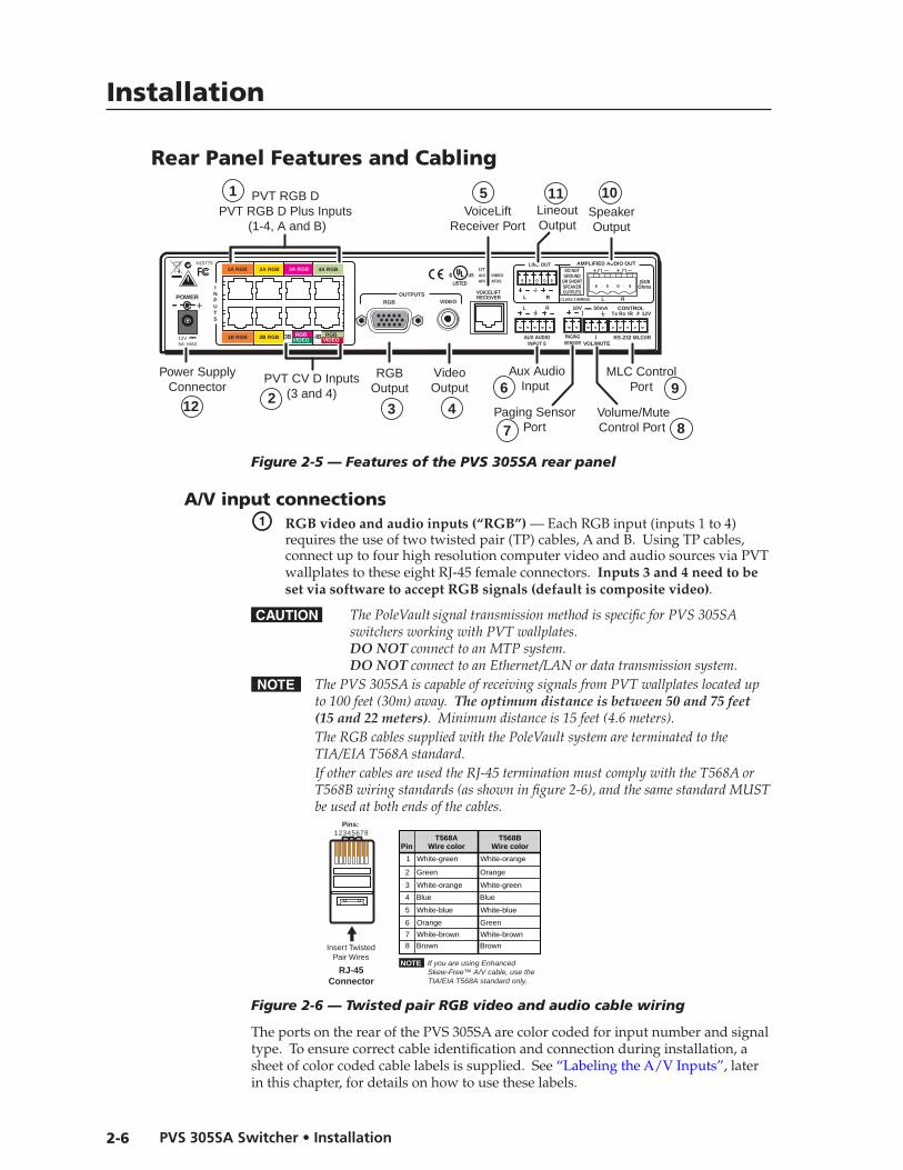
Figure 2-5 — Features of the PVS 305SA rear panel
A/V input connectionsa RGB video and audio inputs (“RGB”) — Each RGB input (inputs 1 to 4)
requires the use of two twisted pair (TP) cables, A and B. Using TP cables, connect up to four high resolution computer video and audio sources via PVT wallplates to these eight RJ-45 female connectors. Inputs 3 and 4 need to be set via software to accept RGB signals (default is composite video).
C ThePoleVaultsignaltransmissionmethodisspecificforPVS305SAswitchersworkingwithPVTwallplates.DO NOTconnecttoanMTPsystem.DO NOTconnecttoanEthernet/LANordatatransmissionsystem.
N ThePVS305SAiscapableofreceivingsignalsfromPVTwallplateslocatedupto100feet(30m)away.The optimum distance is between 50 and 75 feet (15 and 22 meters).Minimumdistanceis15feet(4.6meters).
TheRGBcablessuppliedwiththePoleVaultsystemareterminatedtotheTIA/EIAT568Astandard.
IfothercablesareusedtheRJ-45terminationmustcomplywiththeT568AorT568Bwiringstandards(asshowninfigure2-6),andthesamestandardMUSTbeusedatbothendsofthecables.
12345678
RJ-45Connector
Insert TwistedPair Wires
Pins:
Pin
1
2
3
4
5
6
7
8
Wire color
White-green
Green
White-orange
Blue
White-blue
Orange
White-brown
Brown
Wire colorT568A T568B
White-orange
Orange
White-green
Blue
White-blue
Green
White-brown
Brown
NOTE If you are using Enhanced Skew-Free™ A/V cable, use the TIA/EIA T568A standard only.
Figure 2-6 — Twisted pair RGB video and audio cable wiring
The ports on the rear of the PVS 305SA are color coded for input number and signal type. To ensure correct cable identification and connection during installation, a sheet of color coded cable labels is supplied. See “Labeling the A/V Inputs”, later in this chapter, for details on how to use these labels.

2-7PVS 305SA Switcher • Installation
When connecting the TP cables to the PVS 305SA, take care not to cross-connect the cables; connect input cable 1A to the RJ-45 port labeled 1A, and input cable 1B to the RJ-45 port labeled 1B. Likewise, connect input cables 2A, 3A, or 4A to its corresponding numbered A port, and cable B to its B port (see figure 2-7).
PVT RGB DInput #2
RGB BOUT
Rear Panel
RGB AOUT
INPUTS
RGB
RGB Input Connectors onRear Panel of PVS 305SA
Cable from PVT Output A
Cable from PVT Output B
Cable from PVT Output A
Cable from PVT Output B
1A 2A
1B 2B
N15779
POWER
12V5A MAX
PVT RGB DInput #1
RGB BOUT
Rear Panel
RGB AOUT
Figure 2-7 — Connect RGB wallplate output cables to the switcher RGB inputs.
b Composite video and audio inputs (”Video”) — Each composite video input needs one TP cable. Using TP cable, connect up to two composite video and audio sources via PVT wallplates to these two RJ-45 female connectors labeled 3 and 4; each one is for video and audio combined.
N These ports can also be configured via RS-232 for RGB video input. Default is for composite video.
WhenconnectingtheTPcablestotheswitcher,takecaretoconnectinput3’scabletotheRJ-45portlabeled3,andinput4’scabletotheRJ-45portlabeled4(seefigure2-8).
ThoughtheseportscanalsobeusedforRGBsignals,donotconnectanRGBcable(cableA)tothetopportswhenconnectingcompositevideoinputstothelowerports.
Seethenoteonpage2-6aboutcablesandcabletermination.
PVT CV DInput #3
PVT CV DInput #4
Rear Panel Rear Panel
Composite Video InputConnectors on
Rear Panel of PVS 305SA
Composite VideoCable from PVT Output
3A RGB 4A RGB
RGBVIDEO
RGBVIDEO3B 4B
Figure 2-8 — Connect the composite video wallplate output cables to the switcher video inputs.
3A RGB 4A RGB
RGBVIDEO
RGBVIDEO3B 4B

Installation, cont’d
PVS 305SA Switcher • Installation2-8
PREL
IMIN
ARY
A/V output connectionsc RGB video output — Connect a VGA cable to this female
15-pin HD connector and to the projector RGB input.
d Composite (video) output — Connect an RCA cable to this female RCA jack and to the projector composite input.
VoiceLift connection (optional)�e VoiceLift receiver connector — Connect an optional Extron VoiceLift IR
receiver to this RJ-45 connector for integration of a VoiceLift Microphone system.
N TheExtronVoiceLiftMicrophoneisanoptionalaccessorywhichmustbepurchasedseparately.ToinstalltheVoiceLiftMicrophonesystem,refertothe“VoiceLift Installation Guide”,suppliedwiththedevice.
Aux audio inputf Aux audio input — Input 5 is a dedicated audio only input for an auxiliary,
stereo, line-level audio signal from an audio output source such as audio from a DVI/HDMI device or an MP3 player. Connect a cable from the source to this 5-pole captive screw connector. It can be wired as balanced or unbalanced. See appendix B for wiring details.
Paging sensor connection (optional)�
g Paging system sensor input — Connect the optional Extron Priority Page Sensor to this port to enable audio interrupts during paging system use.
N Enabletheswitcher’spagingsensorport,usingGlobal ConfiguratorortheMediaLink® Switchers (MLS) and PoleVault Switchers (PVS) control software,availableatwww.extron.com.
TheExtronPriorityPageSensorKit(part#70-619-01)isanoptionalaccessorywhichmustbepurchasedseparately.
DC Volume/Mute Control
h DC Volume control port (Vol/Mute) — This port is used to connect an Extron external volume control module, such as a VCM 100 to the PVS 305SA. The range is 0 to 10 V, where 0 V is mute and 10 V is maximum volume. When connected, the external volume control module is the sole volume controller.
N DonotcontrolthePVSvolumeviaRS-232ifthisportisconnectedtoaVCM100.IfaVCM100iscontrollingthevolume,anMediaLinkController(MLC)shouldnotbeconnectedtotheMLC/IR/RS-232port.
Connect the supplied blue, male, 3-pole captive screw connector to this port, wiring the connector as shown in figure 2-9.
VOL/
MU
TE10
V
MUTEVOLUME
VCM 100 MAAP
DC VOL
VOL/MUTE10 V
10 V
Ground
VCM 100 MAAP front and rear panels
PVS 305SADC Volume port
Variable voltage or mute
Figure 2-9 — Wiring a VCM 100 MAAP to the DC volume port
2-9PVS 305SA Switcher • Installation
Switcher control
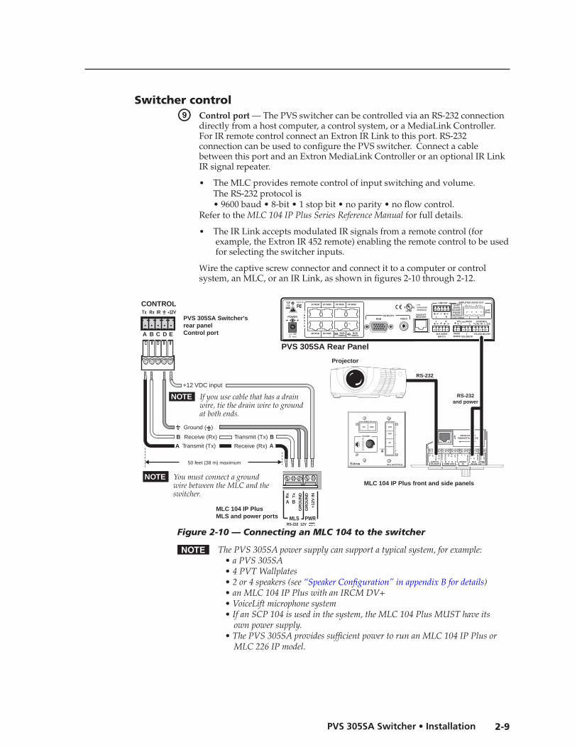
i Control port — The PVS switcher can be controlled via an RS -232 connection directly from a host computer, a control system, or a MediaLink Controller. For IR remote control connect an Extron IR Link to this port. RS-232 connection can be used to configure the PVS switcher. Connect a cable between this port and an Extron MediaLink Controller or an optional IR Link IR signal repeater.
• The MLC provides remote control of input switching and volume. The RS-232 protocol is • 9600 baud • 8-bit • 1 stop bit • no parity • no flow control. Refer to the MLC104IPPlusSeriesReferenceManualfor full details.
• The IR Link accepts modulated IR signals from a remote control (for example, the Extron IR 452 remote) enabling the remote control to be used for selecting the switcher inputs.
Wire the captive screw connector and connect it to a computer or control system, an MLC, or an IR Link, as shown in figures 2-10 through 2-12.
MLC 104 IP Plus front and side panels
2 3
GR
OU
ND1
IR IN
GR
OU
ND
IR O
UT
CM
SCP
GROU
ND
GROU
NDTx Rx
DISPLAYRS-232/IR
LAN PRESS TAB WITH
TWEEKER TO REMOVE
A B
MLS PWRRS-232 12V
DIGITALI/O
A B C D ECOMM LINK
+V O
UT
GR
OU
ND
TxRx
+12V
IN
CONFIG
DISPLAY
VOLUME
MLC 104 IP PLUS
ON VCR
DVD
PC
OFF 1
2
3
4
CONTROL
A B C
PVS 305SA Switcher'srear panelControl port
NOTE You must connect a ground wire between the MLC and the switcher.
MLC 104 IP Plus MLS and power ports
NOTE If you use cable that has a drain wire, tie the drain wire to ground at both ends.
D E
Tx Rx IR +12 V
RS-232 12VMLS PWR
A B
Rx
Tx
GR
OU
ND
GR
OU
ND
+12V
IN
Ground ( )
Transmit (Tx)
B Receive (Rx)
A
Transmit (Tx)
Receive (Rx)
B
A
+12 VDC input
50 feet (38 m) maximum
PVS 305SA Rear Panel
L RL R
L R
AUX AUDIOINPUT 5
LINE OUT
VOICELIFTRECEIVER
PAGINGSENSOR
DO NOTGROUND
OR SHORTSPEAKEROUTPUTS
1B RGB
1A RGB
2B RGB
2A RGB
RGBVIDEO
RGBVIDEO
3A RGB 4A RGB
INPUTS
RS-232 MLC/IR
2/4/8Ohms
CLASS 2 WIRING
AMPLIFIED AUDIO OUT
VOL/MUTE
Tx Rx IR 12V10V 50mA
POWER
US
LISTED
17TTAUDIO/VIDEOAPPARATUS
®
RGB VIDEOOUTPUTS
CONTROL
N15779
12V5A MAX
RS-232
RS-232and power
Projector
4B3B
Figure 2-10 — Connecting an MLC 104 to the switcher
N ThePVS305SApowersupplycansupportatypicalsystem,forexample: • aPVS305SA •4PVTWallplates •2or4speakers(see“SpeakerConfiguration”inappendixBfordetails) •anMLC104IPPluswithanIRCMDV+ •VoiceLiftmicrophonesystem • IfanSCP104isusedinthesystem,theMLC104PlusMUSThaveits ownpowersupply. • ThePVS305SAprovidessufficientpowertorunanMLC104IPPlusor MLC226IPmodel.

Installation, cont’d
PVS 305SA Switcher • Installation2-10
PREL
IMIN
ARY
PVS 305SA Rear Panel
L RL R
L R
AUX AUDIOINPUT 5
LINE OUT
VOICELIFTRECEIVER
PAGINGSENSOR
DO NOTGROUND
OR SHORTSPEAKEROUTPUTS
1B RGB
1A RGB
2B RGB
2A RGB
RGBVIDEO
RGBVIDEO
3A RGB 4A RGB
INPUTS
RS-232 MLC/IR
2/4/8Ohms
CLASS 2 WIRING
AMPLIFIED AUDIO OUT
VOL/MUTE
Tx Rx IR 12V10V 50mA
POWER
US
LISTED
17TTAUDIO/VIDEOAPPARATUS
®
RGB VIDEOOUTPUTS
CONTROL
N15779
12V5A MAX
4B3B
RS-232 portof a computer orcontrol system
PVS 305SA Switcherrear panelControl port
NOTE If you use cable that has a drain wire, tie the drain wire to ground at both ends.
Tx Rx IR +12V
A B C D E
CONTROL
Host Computer
Control System
or
Transmit (Tx)
Receive (Rx)
3
2
Ground ( )
Transmit (Tx)
B Receive (Rx)
A
NOTE Connect a ground wire between the switcher and the computer or control system.
Figure 2-11 — Connecting a computer or control system
CONTROLTx Rx IR +12V PVS 305SA
Switcherrear panelControl port
IR Linkport
A B C D E
150 feet (45.7 m) maximum
+12 VDCGround ( )
IR
A B C D E
IR (IR Link)C D
IR Link front and rear panels
IR 452SIGNAL
DV
D
PVS 305SA Rear Panel
L RL R
L R
AUX AUDIOINPUT 5
LINE OUT
VOICELIFTRECEIVER
PAGINGSENSOR
DO NOTGROUND
OR SHORTSPEAKEROUTPUTS
1B RGB
1A RGB
2B RGB
2A RGB
RGBVIDEO
RGBVIDEO
3A RGB 4A RGB
INPUTS
RS-232 MLC/IR
2/4/8Ohms
CLASS 2 WIRING
AMPLIFIED AUDIO OUT
VOL/MUTE
Tx Rx IR 12V10V 50mA
POWER
US
LISTED
17TTAUDIO/VIDEOAPPARATUS
®
RGB VIDEOOUTPUTS
CONTROL
N15779
12V5A MAX
4B3B
Figure 2-12 — Connecting an IR Link to the switcher

2-11PVS 305SA Switcher • Installation
Speaker output
j Amplified audio out — Connect one speaker to each channel marked “L” and “R” (left and right) using the supplied black 4-pin 5 mm connector. Wire the red cable to positive and the black cable to negative. Each channel is rated for 25 W at 2, 4, or 8 ohm loads.
If using more than one speaker per channel, connect them in parallel.Refer to appendix B, “Speaker Configuration” section, for details on speaker configuration.
C Do not tie both L and R outputs to each other and/or to groundasitmayshorttheoutputsanddamagetheamplifier.
N Thespeakersetupcoverstwoindividualspeakersof8ohmimpedanceortwopairsofspeakersinparallel,whereeachchanneldrivesamaximumoutputloadof2ohms.
Line out audio output
k Line out audio port — This port is used for connecting an Extron external amplifier, recording, podcasting, or assisted listening devices. It can be configured via RS-232 for fixed or variable audio output (default is variable). It can be wired for balanced or unbalanced signals. See appendix B for wiring details.
Power supply connectorl DC power connector — When all other cables have been connected, plug
the round power jack from the 12 VDC power source into this connector to power the switcher, the PVT wallplates, the MediaLink controller and, where installed, the VoiceLift receiver. One of the five front panel input button LED is lit when the PVS 305SA is receiving power.
N Useonlythesupplied12V,5Apowersupplyforthisswitcher.
ThePVS305SApowersupplycansupportatypicalsystem:forexample,aPVS305SA,4PVTWallplates,2or4speakers,anMLC104IPPluswithanIRCMDV+,andaVoiceLiftMicrophonesystem.
IfanSCP104isusedinthesystem,theMLC104IPPlusMUSThaveitsownpowersupply.
L R
2/4/8 OhmsAMPLIFIED OUTPUTS
L R
LINE OUT

Installation, cont’d
PVS 305SA Switcher • Installation2-12
PREL
IMIN
ARY
Labeling the A/V Inputs
Labeling and connecting the A/V input cablesThe RGB and composite video input ports on the rear of the PVS 305SA are color coded to aid easy identification of the input signal type. A sheet of corresponding colored labels is supplied for the installer to label the cables running from the PVT Wallplates to the switcher. Once the labels are attached to the cables, the signal type transmitted on any cable can clearly be identified, enabling correct cable connection during installation.
To label the cables,
1. Peel off the label corresponding to the cable’s signal type (see the table below) and affix it close to one end of the cable.
N Alignandpressthecoloredsectionofthelabeltothecablefirst,thenwraptheclearsectionaroundthecable,allowingthesignaltypenametobeeasilyread.
Figure 2-12 — Wrap the label around the cable, colored part first.
2. Repeat step 1 for the other end of the cable, using the same label type.
3. Using the correct label type, repeat steps 1 and 2 as necessary for all signal cables that are to be connected to the PVS 305SA.
4. Connect the colored coded cable to the corresponding color coded port (see table below).
L RL R
L R
AUX AUDIOINPUT 5
LINE OUT
VOICELIFTRECEIVER
PAGINGSENSOR
DO NOTGROUND
OR SHORTSPEAKEROUTPUTS
1B RGB
1A RGB
2B RGB
2A RGB
3B RGB/VIDEO
4B RGB/VIDEO
3A RGB 4A RGB
INPUTS
RS-232 MLC/IR
2/4/8Ohms
CLASS 2 WIRING
AMPLIFIED AUDIO OUT
VOL/MUTE
Tx Rx IR 12V10V 50mA
POWER
US
LISTED
17TTAUDIO/VIDEOAPPARATUS
®
RGB VIDEOOUTPUTS
CONTROL
N15779
12V5A MAX
1B RGB 2B RGB RGBVIDEO3B RGB
VIDEO 4B
RGB #1A
VIDEO #4
2A RGB1A RGB 4A RGB3A RGB
RGB #1B
Figure 2-13 — Connect the cables to the relevant input port.
Cable Input Signal Input Port # Background Color Text color
RGB (cable A) 1A Orange Black
RGB (cable B) 1B Orange Black
RGB (cable A) 2A Yellow Black
RGB (cable B) 2B Yellow Black
RGB (cable A) 3A Magenta White
RGB (cable B) 3B Magenta White
RGB (cable A) 4A Pale Green Black
RGB (cable B) 4B Pale Green Black
Video 3B Green White
Video 4B Red White
RGB #1A

2-13PVS 305SA Switcher • Installation
Labeling the PVT Decora face platesTo help identify the input number and type of signal that any PVT Decora wallplate sends to the PVS switcher when the wallplate is installed, a series of small labels are supplied. A label identifying the transmitted signal type should be affixed to each Decora face plate (top or bottom) where it can easily be seen after installation. This aids the user to connect a device corresponding to the plate transmission signal type, allowing correct input switching at the PVS 305SA.
Final SetupWith an MLC 104 IP Plus as a standard MLC controller in the PoleVault system package, your final PVS 305SA switcher setup should look similar to the figure below.
Ensure all connections are correctly made and secure.
N RefertothePoleVault Installation GuideandMLC 104 Plus Series Setup GuideforfullMLCinstallation,configuration,andoperatingdetails.
FF 120Speakers
L RL R
L R
AUX AUDIOINPUT 5
LINE OUT
VOICELIFTRECEIVER
PAGINGSENSOR
DO NOTGROUND
OR SHORTSPEAKEROUTPUTS
1B RGB
1A RGB
2B RGB
2A RGB
3B RGB/VIDEO
4B RGB/VIDEO
3A RGB 4A RGB
INPUTS
RS-232 MLC/IR
2/4/8Ohms
CLASS 2 WIRING
AMPLIFIED AUDIO OUT
VOL/MUTE
Tx Rx IR 12V10V 50mA
POWER
US
LISTED
17TTAUDIO/VIDEOAPPARATUS
®
RGB VIDEOOUTPUTS
CONTROL
N15779
12V5A MAX
2A RGB1A RGB
1B RGB 2B RGB
4A RGB3A RGB
RGBVIDEO3B RGB
VIDEO 4B
DVD Player
PVT RGB D
PVT RGB D
COMPUTER IN
AUDIO IN
PVT CV D
AUDIO IN
L R
VIDEO IN
IR OUT
S G
MLC 104 IP Plus
RS-232 RS-232
Projector
+V G
SCP
+12V
OUT
PWR
SNS
GR
OU
ND
GR
OU
ND
GR
OU
ND
GROU
ND
GROU
NDTx Rx
HOST/CONFIG
LAN PRESS TAB WITH
TWEEKER TO REMOVE
A BA B E
SCPCOMM
MLSRS-232
PWR12V
PROJECTORRS-232/IR
Tx/IR R
x TxRx
+12V
IN
Laptop
PC
COMPUTER IN
AUDIO IN
Figure 2-14 — MLC 104 IP Plus controller and other typical devices connected to the PVS switcher.
RGB IN #1

PVS 305SA
3Chapter Three
Operation and Setup
Front Panel Features� and Operation
Setting Switcher Modes�
Auto Switching
Setting Up and Optimizing the Audio
Res�etting the Switcher
Executive Mode (Front Panel Security Lockout)�

PVS 305SA Switcher • Operation and Setup3-2
Operation and Setup
PREL
IMIN
ARY
Front Panel Features and Operation PVS 305SA
POLEVAULT SWITCHERINPUT SELECTION
1 2PEAK
NORMAL
SIGNAL
CONFIG
3 4 5
AUX AUDIO
AUDIO LEVEL ADJUSTPAGINGSENSOR
SENSITIVITYVOICELIFT
MICPEAK
NORMAL
SIGNAL
INPUT
21 64 53
Figure 3-1 — Front panel features
a Configuration port — This 2.5 mm port (jack) can be used to configure the PVS 305SA during setup via RS-232. Use the optional 2.5 mm configuration cable, part # 70-335-01 (see figure 3-2), for connection to your PC’s serial port.
6 feet
5
1
9
6
Sleeve (Gnd)
Ring
Tip
9-pin D Connection TRS Plug
Pin 2 Computer's RX line Tip Pin 3 Computer's TX line Ring Pin 5 Computer's signal ground Sleeve
Figure 3-2 — Front 2.5 mm port configuration cable (part # 70-335-01)
N Extronrecommendsusingthisporttouploadfirmwarewherenecessary.
b Video input selection buttons and indicator LEDs — Press one of these buttons to select the desired audio and video input. The corresponding green LED lights and remains lit while the input is selected. These buttons are also used to configure the switcher.
c Aux audio input button and LED — Input 5 is a dedicated audio only input for an auxiliary, stereo, line-level audio signal from an audio output source such as a DVI/HDMI device or an MP3 player. The green LED lights and remains lit while the input is selected.
d Input audio adjustment knob and LEDs — Use this knob to adjust the input levels through 43 positions in 1 dB steps (-18 to +24 dB, default 0). The LEDs indicate level set (see page 3-5 for details).
e VoiceLift MIC adjustment knob and LEDs — Use this knob to adjust the microphone levels through 43 positions in 1 dB steps (-18 to +24 dB, default 0). The LEDs indicate level set (see page 3-6 for details). This input is not affected by volume adjustment, bass, treble and loudness control via RS-232 or MediaLink®
control.
f Page Sensitivity adjustment knob — Use this knob to make adjustments to the sensitivity of the paging system, where installed (see page 3-6 for details).

3-3PVS 305SA Switcher • Operation and Setup
PREL
IMIN
ARY
Front panel operationN Seethefrontpanelimage(figure3-1)forthelocationofinputbuttons,adjustment
knobs,LEDs,andconfigurationport.
• To change inputs, select an input button, 1 through 4 (video and audio), or 5 (audio only).
• To adjust audio input levels, rotate the Input adjustment knob through 43 positions in 1 dB steps (-18 to +24 dB, default 0).
• To adjust VoiceLift microphone levels, rotate the MIC adjustment knob through 43 positions in 1dB steps (-18 to +24 dB, default 0).
N FrontpanelLEDsindicateinputandmiclevels(seeimageatright).Oninitialswitcherpower-uptheamplifierlevelisautomaticallyadjustedto50%.
• To adjust paging sensitivity, rotate the Paging knob clockwise to increase and counter-clockwise to decrease sensitivity.
ConfigurationThe PVS 305SA switcher can be controlled by a MediaLink Controller (MLC) or by an RS-232 device acting through the MLC. Alternatively, the switcher can be set up and controlled via a host computer or other device (such as a control system) attached to the switcher’s rear panel RS-232/MLC/IR port. The control device (host) can use either the Extron Simple Instruction Set (SIS™) commands, the Global Configurator (GC) program for Windows, or the MediaLink Switchers (MLS) and PoleVault Switchers (PVS) control software,available at www.extron.com.
Firmware updates can be made via the front panel configuration port before installation (connect a2.5mmconfigurationcable,part#70-335-01, to the serial port on the front panel). After installation they can be made through a IP link via the MediaLink Controller connected to the PVS 305SA’s rear RS-232 port.
N Refertochapter4 forafulllistoftherelevantSIScommands.
Inputs 3 and 4 can be configured for signal type (RGB or composite video) via RS-232 and SIS commands. The default is composite video.
Resetting the SwitcherThe switcher can be reset to the factory defaults via the front panel or RS-232.
To reset the switcher via the front panel, follow these steps.
1. Unplug the switcher from the power source.
2. Press and hold input selection button 1 while reapplying power to the switcher. All input selection LEDs blink for 1 second during switcher reset.
For details on RS-232 control, see chapter 4, “Serial Communication”.
PEAK
NORMAL
SIGNAL Signal threshold;raise input gain.
Level has beenproperly adjusted.
Level set too high,lower input gain.

Operation and Setup, cont’d
PVS 305SA Switcher • Operation and Setup3-4
PREL
IMIN
ARY
Executive Mode (Front Panel Security Lockout)�To prevent accidental or unauthorized changes to settings, the PVS switcher has a front panel security lockout (executive mode) that limits users’ access to front panel controls. When the executive mode is active, all functions are locked. To turn executive mode on or off via the front panel:
1. Press and hold input selection buttons 1 and 4 simultaneously for 4 seconds (see figure 3-2). All the input LEDs light.
2. Release the buttons. The LEDs extinguish except for the currently selected input. The switcher has enabled or disabled the executive mode.
Press and hold buttons 1 and 4 simultaneously for 4 seconds.
AUX AUDIO
INPUT SELECTION
1 2 3 4 5
All input LEDs light. to indicate that Release the buttons. The LEDs extinguish except for the currently selected input.Executive mode has been enabled/disabled.
INPUT SELECTION
1 2 3 4 5
Figure 3-3 — Setting the executive mode via the front panel
This mode can also be turned on or off through RS-232 control. For details on RS-232 control, see chapter 4, “Serial Communication”.
Setting Up and Optimizing the AudioThe following steps ensure optimal sound is achieved by configuring the switcher. For each step, refer to the sections indicated for more information.
Steps for optimizing the audio1. Ensure all the settings are at default. These are the settings the PVS has upon
initial power up. The default settings are as shown below.
• Volume is set at 50%.• Bass and treble are set at 0.• Amplifier level is set to 50%.• Loudness control is set to Off.
N Amplifierlevelandvolumelevelarenotthesameadjustments.VolumecanonlybeadjustedbyRS-232orwithapotentiometerconnectedtotherearpanelportlabeled“DCVol”.AmplifierlevelcanonlybeadjustedviaRS-232orcontrolsoftware.
2. Ensure that the PVT transmitters are connected to the PVS and that there is an audio input source present at each of the transmitters. Refer to the transmitters’ user’s manual for installation/connection information.
3. Ensure a set of speakers are connected to the PVS 305SA. See appendix B, “Speaker Configuration” section, for details.
4. Slowly adjust the volume to 100% via RS-232, by having the MLC increase the volume, or by a potentiometer connected to the DC Volume port on the rear panel. If an MLC 104 IP Plus is connected to the PVS, simply rotate the volume knob clockwise until it is at full volume.
5. Adjust the input sensitivity for one input through the front panel or byRS-232 control software to a level just below where audio input is peaking. See the sections “Individual channel input sensitivity control” and “Front panel input sensitivity control”, later in this chapter, for details. Repeat for all five inputs.
N Adjustinginputsensitivityforallinputsensuresthatallinputsareatthesamelevel,andatthehighestlevelpossiblebeforepeakingoccurs.Step5ensuresthatwhenthevolumeisat100%theaudiosignalwillnotbedistorted(clipped).
3-5PVS 305SA Switcher • Operation and Setup
PREL
IMIN
ARY
6. When adjustments to all five inputs’ sensitivity settings have been made, then adjust the amplifier level (via RS-232 only). Increase or decrease the amplifier level very slowly, if needed.
N Ifthevolumeisat100%throughtheMLCandtheoutputonthespeakersistooloud,reducingtheamplevelviaRS-232controlsoftwareisrecommended.Thisensuresthatthevolumewillnotbetooloud,evenwhensetat100%.
7. Fine tune the audio by making adjustments to the bass, treble, and loudness until the desired settings are reached. See “Bass, treble, and loudness control” later in this chapter.
Gain control
Individual channel input sensitivity controlIndividual channel input gain control adjustments are made by rotating the adjustment knob for the selected input button. The adjustment range is -18 dB to +24 dB, with the default set at 0 dB.N Adjustinginputsensitivityforallinputsensuresthatallinputsareatthesame
levelandatthehighestlevelpossiblebeforeclippingoccurs. Individualchannelinputgainlevelseitheraddstoorsubtractsfromtheoverall
(global)poweramplifiergainlevelperchannel.
Front panel input sensitivity adjustmentN Uponinitialpowerupoftheswitcher,theamplifierlevelisautomatically
adjustedto50%.
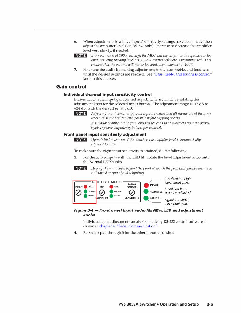
To make sure the right input sensitivity is attained, do the following:
1. For the active input (with the LED lit), rotate the level adjustment knob until the Normal LED blinks.
N HavingtheaudiolevelbeyondthepointatwhichthepeakLEDflashesresultsinadistortedoutputsignal(clipping).
PEAK
NORMAL
SIGNAL
AUDIO LEVEL ADJUSTPAGINGSENSOR
SENSITIVITYVOICELIFT
MICPEAK
NORMAL
SIGNAL
INPUTPEAK
NORMAL
SIGNALSignal threshold;raise input gain.
Level has beenproperly adjusted.
Level set too high,lower input gain.
Figure 3-4 — Front panel Input audio Min/Max LED and adjustment knobs
Individual gain adjustment can also be made by RS-232 control software as shown in chapter 4, “Serial Communication”.
4. Repeat steps 1 through 3 for the other inputs as desired.
Operation and Setup, cont’d
PVS 305SA Switcher • Operation and Setup3-6
PREL
IMIN
ARY
Amplifier level control Amplifier level control is adjusted via RS-232 or control software only. See chapter 4, “Serial Communication”, for details on RS-232 control.
Bass, treble, and loudness controlFor optimum audio quality, the audio input levels and the bass, treble, and loudness controls must all be set up properly. Input audio levels may need to be adjusted depending on the variation of the output levels from different source devices.
N Bydefaulttheselevelsaresetfortheconsumerproductlevelof-10dBV.
Bass and treble should be adjusted once the input and output levels have been adjusted. These are adjusted by RS-232 control only, with a range from -10 dB to +10 dB. By default the bass and treble have been set at 0 dB. See chapter 4, “Serial Communication”, for details on RS-232 control.
The loudness on/off (default off) switch function is also controlled by RS-232.
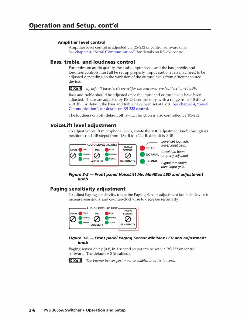
VoiceLift level adjustmentTo adjust VoiceLift microphone levels, rotate the MIC adjustment knob through 43 positions (in 1 dB steps) from -18 dB to +24 dB, default is 0 dB.
PEAK
NORMAL
SIGNAL
AUDIO LEVEL ADJUSTPAGINGSENSOR
SENSITIVITYVOICELIFT
MICPEAK
NORMAL
SIGNAL
INPUTPEAK
NORMAL
SIGNALSignal threshold;raise input gain.
Level has beenproperly adjusted.
Level set too high,lower input gain.
Figure 3-5 — Front panel VoiceLift Mic Min/Max LED and adjustment knob
Paging sensitivity adjustmentTo adjust Paging sensitivity, rotate the Paging Sensor adjustment knob clockwise to increase sensitivity and counter-clockwise to decrease sensitivity.
PEAK
NORMAL
SIGNAL
AUDIO LEVEL ADJUSTPAGINGSENSOR
SENSITIVITYVOICELIFT
MICPEAK
NORMAL
SIGNAL
INPUTPEAK
NORMAL
SIGNALSignal threshold;raise input gain.
Level has beenproperly adjusted.
Level set too high,lower input gain.
Figure 3-6 — Front panel Paging Sensor Min/Max LED and adjustment knob
Paging sensor delay (0-8, in 1 second steps) can be set via RS-232 or control software. The default = 0 (disabled).
N ThePagingSensorportmustbeenabledinordertowork.

PVS 305SA
4Chapter Four
Serial Communication
RS-232 Programmer’s� Guide
Updating Firmware

PVS 305SA • Serial Communication4-2
Serial Communication
PREL
IMIN
ARY
PREL
IMIN
ARY
The PVS 305SA switcher can be remotely set up and controlled via a host computer or other device (such as a control system) attached to the rear panel Control port. Alternatively, the switcher can be controlled by an MediaLink Controller (MLC) (connected to the same port) or by an RS-232 device acting through the MLC. The control device (host) can use either the Extron Simple Instruction Set (SIS™) commands or the Global Configurator program for Windows. For details on use and setup of a system that includes a MLC, refer to the MediaLink Controller user’s manual.Switcher protocol:• 9600 baud • 1 stop bit • no parity • no flow control
Control connector pin assignments:
N Configurationcanalsobecompletedbyconnectinga2.5mmstereominicable(part#70-335-01)tothe2.5mmjack(port)onthefrontpanel.ThisporthasthesameprotocolastheRS-232connectorontherearpanel.
6 feet
5
1
9
6
Sleeve (Gnd)
Ring
Tip
9-pin D Connection TRS Plug
Pin 2 Computer's RX line Tip Pin 3 Computer's TX line Ring Pin 5 Computer's signal ground Sleeve
Figure 3-1 — Pinout diagram for 2.5 mm mini cable TRS plug when connecting to the front panel Config port
N FirmwareupdatescanbemadeonlyviathefrontpanelConfigport.
RS-232 Programmer’s Guide
Host-to-PVS communicationsSIS commands consist of one or more characters per field. No special characters are required to begin or end a command sequence. When the PVS switcher determines that a command is valid, it executes the command and sends a response to the host device. All responses from the switcher to the host end with a carriage return and a line feed (CR/LF = ]), which signals the end of the response character string. A string is one or more characters.
PVS-initiated messagesWhen a local event such as a front panel selection or adjustment takes place, the PVS responds by sending a message to the host. No response is required from the host. The PVS-initiated messages are listed here (underlined).
© Copyright 2009, Extron Electronics, PVS 305SA, V1.xx
The PVS sends the copyright message when it first powers on. V1.xx is the firmware version number.
CONTROLTx Rx IR +12V
A B C ED
(A) Transmit (Tx)(B) Receive (Rx)(C) IR in
(E) +12 VDC out(D) Ground ( )

4-3PVS 305SA • Serial Communication
PREL
IMIN
ARY
PREL
IMIN
ARY
Error responsesWhen the PVS switcher receives a valid SIS command, it executes the command and sends a response to the host device. If the PVS is unable to execute the command because the command is invalid or it contains invalid parameters, it returns an error response to the host.
The error response codes and their descriptions are as follows:
E01 – Invalid input channel number (too large) E06 – Invalid channel change E10 – Invalid command E13 – Invalid value (too large) E14 – Invalid command for this configuration
Using the command/response tablesThe command/response tables in this chapter list valid command ASCII codes, the PVS’s responses to the host, and a description of the command’s function or the results of executing the command. Upper and lower case characters may be used interchangeably in the command field unless otherwise specified (setting gain/attenuation, for example).
The ASCII to hexadecimal (HEX) conversion table below is for use with the command/response tables.
ASCII to HEX Conversion Table
•
ASCII to Hex conversion table
Symbol definitions] = CR/LF (carriage return/line feed) (hex 0D 0A)} = CR (carriage return)
E = Escape key
X! = Specific input number (0 through 5 and 7)0 = all output mute, both audio and video 1 and 2 = RGB inputs (also 1 and 2 in RGB/VGA group) 3 and 4 = RGB or composite video inputs 5 = Auxiliary audio only (not applicable with audio and video breakaway commands). Not a switchable input. 7 = IR receiver microphone audio (not applicable with audio and video breakaway commands). Not a switchable input. 8 = IR receiver auxiliary audio (not applicable with audio and video breakaway commands). Not a switchable input.
X@ = Status 1 = Dual mono 2 = Stereo
Serial Communication, cont’d
PVS 305SA • Serial Communication4-4
PREL
IMIN
ARY
PREL
IMIN
ARY
X# = Status, 0 = off/disable (default) 1 = on/enable
= Signal detection threshold 0 = off (signal level too low to detect) 1 = on (a signal of a least -20 dBv [-18 dBu] is present)
= Normal range 0 = off (input level is too low) 1 = on (input is in the right range)
= Peak level 0 = off (audio input is set up correctly) 1 = on (the level or gain is too high, audio clips/distorts. Output equipment could be damaged. Adjust the input level so that only the Normal LED is blinking. The Peak LED should not turn on)
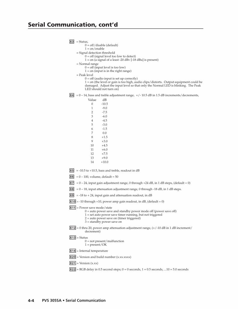
X$ = 0 – 14, bass and treble adjustment range, +/- 10.5 dB in 1.5 dB increments/decrements,
Value dB0 -10.51 -9.02 -7.53 -6.04 -4.55 -3.06 -1.57 0.08 +1.59 +3.010 +4.511 +6.012 +7.513 +9.014 +10.0
X% = -10.5 to +10.5, bass and treble, readout in dB
X^ = 0 – 100, volume, default = 50
X& = 0 – 24, input gain adjustment range, 0 through +24 dB, in 1 dB steps, (default = 0)
X* = 0 – 18, input attenuation adjustment range, 0 through -18 dB, in 1 dB steps.
X( = -18 to + 24, input gain and attenuation readout, in dB
X1) = -10 through +10, power amp gain readout, in dB, (default = 0)
X1! = Power save mode/state 0 = auto power save and standby power mode off (power save off) 1 = set auto power save timer running, but not triggered 2 = auto power save on (timer triggered) 3 = standby power save on
X1@ = 0 thru 20, power amp attenuation adjustment range, (+/-10 dB in 1 dB increment/decrement)
X1# = Status0 = not present/malfunction 1 = present/OK
X1$ = Internal temperature
X2) = Version and build number (x.xx.xxxx)
X2! = Version (x.xx)
X2@ = RGB delay in 0.5 second steps; 0 = 0 seconds, 1 = 0.5 seconds, ...10 = 5.0 seconds

4-5PVS 305SA • Serial Communication
PREL
IMIN
ARY
PREL
IMIN
ARY
X2# = Video type (inputs 3 and 4 only)1 = Composite video (default) 2 = RGB
X2$ = Video signal status0 = Video signal not detected 1 = Video signal present
X2% = 0 to 15, mic talk-over threshold level range, default 6
X2^ = 0 to 30, program ducking level in talk over mode, default = 15
X2& = Lineout status1 = variable 2 = fixed 3 = independent separate mono Left channel fixed and mono Right channel variable
X2( = 0-8, paging delay in 1 second steps, (default = 0, disabled)0 = 0 second (disabled), 1 = 1.0 seconds, 2 = 2.0 seconds...8 = 8.0 seconds
X3^ = Pass through mode0 = not in pass-through mode (default) 1 = in pass-through mode
Factory defaultsInput audio gain X& = 0
Power amp gain X1) = 0
Volume X^ = 50
Bass level X$ = 7
Treble level X$ = 7
Power mode X1! = 1
Audio output X@ = 1
Loudness X# = 0
VoiceLift input gain X& = 0
Video type X2# = 1
Audio mute X# = 0
VoiceLift receiver aux input X# = 0
Front panel executive mode X# = 0
RGB delay X2@ = 0
Mic talk-over threshold X2% = 6
Program audio ducking X2^ = 15
Lineout mode X2& = 1
High pass filter X# = 0
Paging sensor delay X2( = 0
Pass-through mode X3^ = 0
Serial Communication, cont’d
PVS 305SA • Serial Communication4-6
PREL
IMIN
ARY
PREL
IMIN
ARY
Command ASCII command(host to processor)�
Response(processor to host)�
Additional description
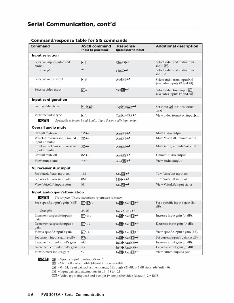
Input selection
Select an input (video and audio)
X!! ChnX!] Select video and audio from input X!.
Example: 2! Chn2] Select video and audio from input 2
Select an audio input X!$ AudX!] Select audio from input X! (excludes inputs #7 and #8)
Select a video input X!& VidX!] Select video from input X! (excludes inputs #7 and #8)
Input configuration
Set the video type X!*X2#\ TypX!=X2#] Set input X! to video format X2#.
View the video type X!\ TypX!=X2#] View video format on input X!.
N Applicabletoinputs3and4only.Input5isanaudioinputonly.
Overall audio mute
Overall mute on 1Z} AmtX#] Mute audio output.
VoiceLift receiver input muted, input unmuted
2Z} AmtX#] Mute VoiceLift, unmute input
Input muted, VoiceLift receiver input unmuted
3Z} AmtX#] Mute input, unmute VoiceLift
Overall mute off 0Z} AmtX#] Unmute audio output.
View mute status Z} AmtX#] View audio output.
VL receiver Aux input
Set VoiceLift aux input on 1M MixX#] Turn VoiceLift input on.
Set VoiceLift aux input off 0M MixX#] Turn VoiceLift input off.
View VoiceLift input status M MixX#] View VoiceLift input status.
Input audio gain/attenuation
N Thesetgain(G)andattenuation(g)arecasesensitive.
Set a specific input’s gain (+dB) X!*X&G InX!•AudX(] Set a specific input’s gain (in dB).
Example: 2*12G In2•Aud12]Increment a specific input’s gain
X!*+G InX!•AudX(] Increase input gain (in dB).
Decrement a specific input’s gain
X!*-G InX!•AudX(] Decrease input gain (in dB).
View a specific input’s gain X!*G InX!•AudX(] View specific input’s gain (dB).
Set current input’s gain (+dB) X&G InX!•AudX(] Set current input’s gain (in dB).
Increment current input’s gain +G InX!•AudX(] Increase input gain (in dB).
Decrement current input’s gain -G InX!•AudX(] Decrease input gain (in dB).
View current input’s gain G InX!•AudX(] View current input’s gain.
Command/response table for SIS commands
N X! = Specific input number, 0-5 and 7 X# = Status: 0 = off/disable (default), 1 = on/enableX& = 0 – 24, input gain adjustment range, 0 through +24 dB, in 1 dB steps, (default = 0)X( = Input gain and attenuation, in dB, -18 to +24X2# = Video types (inputs 3 and 4 only): 1= composite video (default), 2 = RGB

4-7PVS 305SA • Serial Communication
PREL
IMIN
ARY
PREL
IMIN
ARY
Command ASCII command(host to processor)�
Response(processor to host)�
Additional description
Set a specific input’s attenuation (-dB)
X!*X*g InX!•AudX(] Set a specific input’s attenuation.
Increment a specific input’s attenuation
X!*+g InX!•AudX(] Increase input attenuation.
Decrement a specific input’s attenuation
X!*-g InX!•AudX(] Decrease input attenuation.
View a specific input’s attenuation
X!*g InX!•AudX(] View specific input attenuation.
Set current input’s attenuation (-dB)
X*g InX!•AudX(] Set a specific input’s attenuation.
Increment current input’s attenuation
+g InX!•AudX(] Increase input attenuation.
Decrement current input’s attenuation
-g InX!•AudX(] Decrease input attenuation.
View current input’s attenuation
g InX!•AudX(] View specific input attenuation.
Volume adjustment
Specify volume/variable X^V VolX^] Set a specific volume.
Increment volume +V VolX^] Increase value.
Decrement volume -V VolX^] Decrease value.
View value V VolX^] Show volume.
Bass adjustmentSpecify bass level X$< Bas=X%] Set a specific bass level.
Increment bass level +< Bas=X%] Increase value.
Decrement bass level -< Bas=X%] Decrease value.
View bass level < Bas=X%] Show bass level.
Treble adjustmentSpecify treble level X$> Trb=X%] Set a specific treble level.
Increment treble level +> Trb=X%] Increase value.
Decrement treble level -> Trb=X%] Decrease value.
View treble level > Trb=X%] Show treble level.
N Trebleandbassarestrictlyglobalcommands.TheyonlyadjusttheTPinputs,captivescrewaudioinput,andVoiceLiftreceiverauxprogramaudiosignals.TheydonotadjusttheVoiceLiftreceivermicrophoneaudiosignal.
Front panel lockout modeLock 1X ExeX#] Lock out front panel.
Unlock 0X ExeX#] Unlock front panel.
View lock status X ExeX#] Show lock status.
N X! = Specific input number, 0-5 and 7 X# = Status: 0 = off/disable (default), 1 = on/enableX$ = Bass and treble adjustment range; 0-14, in 1.5 dB increments, e.g., 0 = -10.5,...5 = -3.0,...14 = +10.5 dB X% = Bass and treble reading: - 10.5 to +10.5 dBX^ = Volume, 0-100 (default = 50)X* = 0 – 18, input attenuation adjustment range, 0 through -18 dB, in 1 dB stepsX( = Input gain and attenuation, in dB, -18 to +24

Serial Communication, cont’d
PVS 305SA • Serial Communication4-8
PREL
IMIN
ARY
PREL
IMIN
ARY
Command ASCII command(host to processor)�
Response(processor to host)�
Additional description
Information requestQuery firmware version Q VerX2!]Query firmware and build # *Q VerX2)]Request part # N N60-986-01]Request general information I (or 0I) VidX!•AudX!•VolX!]Request model name 1I PVS 305SA]
System reset (to factory default)�Switcher reset EzXXX} ZapXXX] Reset switcher to factory
defaults.
Firmware uploadUpload EUPLOAD} Go]
Upl]Begins upload. Upload successful.
N Thiscommandiscasesensitiveandmustbeinputasuppercasecharacters.
Status commandsView internal temperature (°C) 20S Sts20*X1$]View switchable signal, normal, and peak status
1S SigX#NormX#ClipX#]
View VL reciever Mic input signal, normal, and peak status
4S SigX#NormX#ClipX#]
View all video status LS Frq=X2$*X2$*X2$*X2$]View VCM present status 40S Sts40*X1#]View paging sensor status 42S Sts42*X#]
Auto and standby power save modesDisable power save E0PSAV} PsavX1!] Turns off auto power save
mode and sets timer to 0.Start auto power save timer E1PSAV} PsavX1!] Timer starts count but is not
triggered.Force auto power save E2PSAV} PsavX1!] Turns on auto power save.
Force standby power mode on E3PSAV} PsavX1!] Turns on standby mode.
Query power save mode EPSAV} PsavX1!] View power mode status.
N Bydefaulttheswitchergoesintoautopowersavemodewhenthereisnoactivesignalfor30minutes.Anunsolicitedresponseissentoutwhentheswitchergoesintooroutofautopowersavemode.
Pass-through modeConfigure pass-through mode E1CD} CpnX3^] Allow pass-through mode.
Terminate pass-through mode E0CD} CpnX3^] Stop pass-through mode.
View pass-through mode ECD} CpnX3^] View pass-through mode status.
N X! = Specific input number, 0-5 and 7 X# = Status: 0 = off/disable (default), 1 = on/enableX1! = Power save mode/state; 0 = auto power save and standby, 1 = auto power save running not triggered, 2 = power save on (timer triggered), 3 = standby power save on X1# = Status, 0 = not present/malfunction, 1 = present/OKX1$ = Internal temperature (degrees C)X2) = Version and build number (x.xx.xxxx)X2! = Input gain and attenuation, in dB, -18 to +24X2$ = Video signal status: 0 = video signal not detected, 1 = video signal not presentX3^ = Pass through mode: 0 = not in pass-through mode (default), 1 = in pass-through mode
Command/response table for SIS commands (continued)�
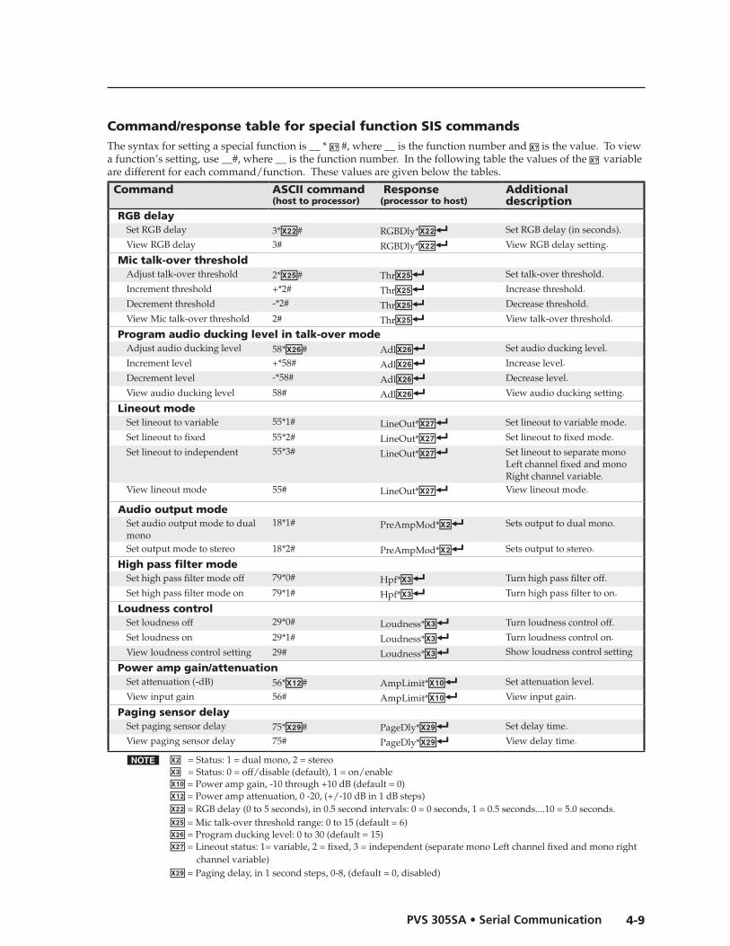
4-9PVS 305SA • Serial Communication
PREL
IMIN
ARY
PREL
IMIN
ARY
N X@ = Status: 1 = dual mono, 2 = stereoX# = Status: 0 = off/disable (default), 1 = on/enableX1) = Power amp gain, -10 through +10 dB (default = 0)X1@ = Power amp attenuation, 0 -20, (+/-10 dB in 1 dB steps)X2@ = RGB delay (0 to 5 seconds), in 0.5 second intervals: 0 = 0 seconds, 1 = 0.5 seconds....10 = 5.0 seconds. X2% = Mic talk-over threshold range: 0 to 15 (default = 6)X2^ = Program ducking level: 0 to 30 (default = 15) X2& = Lineout status: 1= variable, 2 = fixed, 3 = independent (separate mono Left channel fixed and mono right channel variable) X2( = Paging delay, in 1 second steps, 0-8, (default = 0, disabled)
Command/response table for special function SIS commandsThe syntax for setting a special function is __ * X? #, where __ is the function number and X? is the value. To viewa function’s setting, use __#, where __ is the function number. In the following table the values of the X? variable are different for each command/function. These values are given below the tables.
Command ASCII command(host to processor)�
Response(processor to host)�
Additional description
RGB delaySet RGB delay 3*X2@# RGBDly*X2@] Set RGB delay (in seconds).
View RGB delay 3# RGBDly*X2@] View RGB delay setting.
Mic talk-over thresholdAdjust talk-over threshold 2*X2%# ThrX2%] Set talk-over threshold.
Increment threshold +*2# ThrX2%] Increase threshold.
Decrement threshold -*2# ThrX2%] Decrease threshold.
View Mic talk-over threshold 2# ThrX2%] View talk-over threshold.
Program audio ducking level in talk-over modeAdjust audio ducking level 58*X2^# AdlX2^] Set audio ducking level.
Increment level +*58# AdlX2^] Increase level.
Decrement level -*58# AdlX2^] Decrease level.
View audio ducking level 58# AdlX2^] View audio ducking setting.
Lineout modeSet lineout to variable 55*1# LineOut*X2&] Set lineout to variable mode.
Set lineout to fixed 55*2# LineOut*X2&] Set lineout to fixed mode.
Set lineout to independent 55*3# LineOut*X2&] Set lineout to separate mono Left channel fixed and mono Right channel variable.
View lineout mode 55# LineOut*X2&] View lineout mode.
Audio output modeSet audio output mode to dual mono
18*1# PreAmpMod*X@] Sets output to dual mono.
Set output mode to stereo 18*2# PreAmpMod*X@] Sets output to stereo.
High pass filter modeSet high pass filter mode off 79*0# Hpf*X#] Turn high pass filter off.
Set high pass filter mode on 79*1# Hpf*X#] Turn high pass filter to on.
Loudness controlSet loudness off 29*0# Loudness*X#] Turn loudness control off.
Set loudness on 29*1# Loudness*X#] Turn loudness control on.
View loudness control setting 29# Loudness*X#] Show loudness control setting
Power amp gain/attenuationSet attenuation (-dB) 56*X1@# AmpLimit*X1)] Set attenuation level.
View input gain 56# AmpLimit*X1)] View input gain.
Paging sensor delaySet paging sensor delay 75*X2(# PageDly*X2(] Set delay time.
View paging sensor delay 75# PageDly*X2(] View delay time.

Serial Communication, cont’d
PVS 305SA • Serial Communication4-10
PREL
IMIN
ARY
PREL
IMIN
ARY
Updating FirmwareIf the need arises, you can update the PVS 305SA firmware without taking the unit out of service. Follow the directions below.
Check the Extron Web site (www.extron.com) for firmware-related documents, instructions, patch files, and new firmware files before loading new firmware into the switcher. Extron recommends that you read the firmware release notes (available from the Web site www.extron.com) before beginning the firmware update.
This procedure must be performed using a PC, with the PC’s RS-232 port directly cabled to the PVS’s front panel Config port.
N Eachtimeyoureplaceexistingfirmware,theswitcherisresettothefactorydefaultsettings.
1. Visit the Extron Web site (www.extron.com) and download the Firmware Loader file (FWLoader.exe) to your PC. Write down the filename and location for later use.
2. Locate (on the Extron Web site) the appropriate (PVS 305SA) firmware file you want to update. It has a filename ending in .s19 (PVS305SA_Vxxx.s19), where Vxxx indicates the version number (x.xx). Download the firmware from the Web site. The program automatically stores the firmware file on the PC in C:\Program Files\Extron Electronics\Firmware (a folder specific to that file type). Write down the filename and location for later use.
C Thefirmwareupdatefilemusthaveafilenameextensionof.s19.Ifthefiledoesnothavethatextension,itcouldcausetheunittostopfunctioning.
3. Connect a 2.5 mm configuration cable (Extron part # 70-335-01) between the front panel Config port of the PVS and the serial (RS-232) port of the PC, and power up the PVS and PC. See chapter 3, “Operation and Setup”, “Front Panel Features and Operation” section, for details.
4. On the PC, select Start > All Programs > Extron Electronics > Firmware Loader (folder)> Firmware Loader and start the program.
5. Select the Comm port and Baud rate. Click OK. The PVS 305SA should be detected automatically.
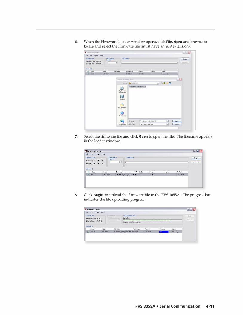
4-11PVS 305SA • Serial Communication
PREL
IMIN
ARY
PREL
IMIN
ARY
6. When the Firmware Loader window opens, click File, Open and browse to locate and select the firmware file (must have an .s19 extension).
7. Select the firmware file and click Open to open the file. The filename appears in the loader window.
8. Click Begin to upload the firmware file to the PVS 305SA. The progress bar indicates the file uploading progress.
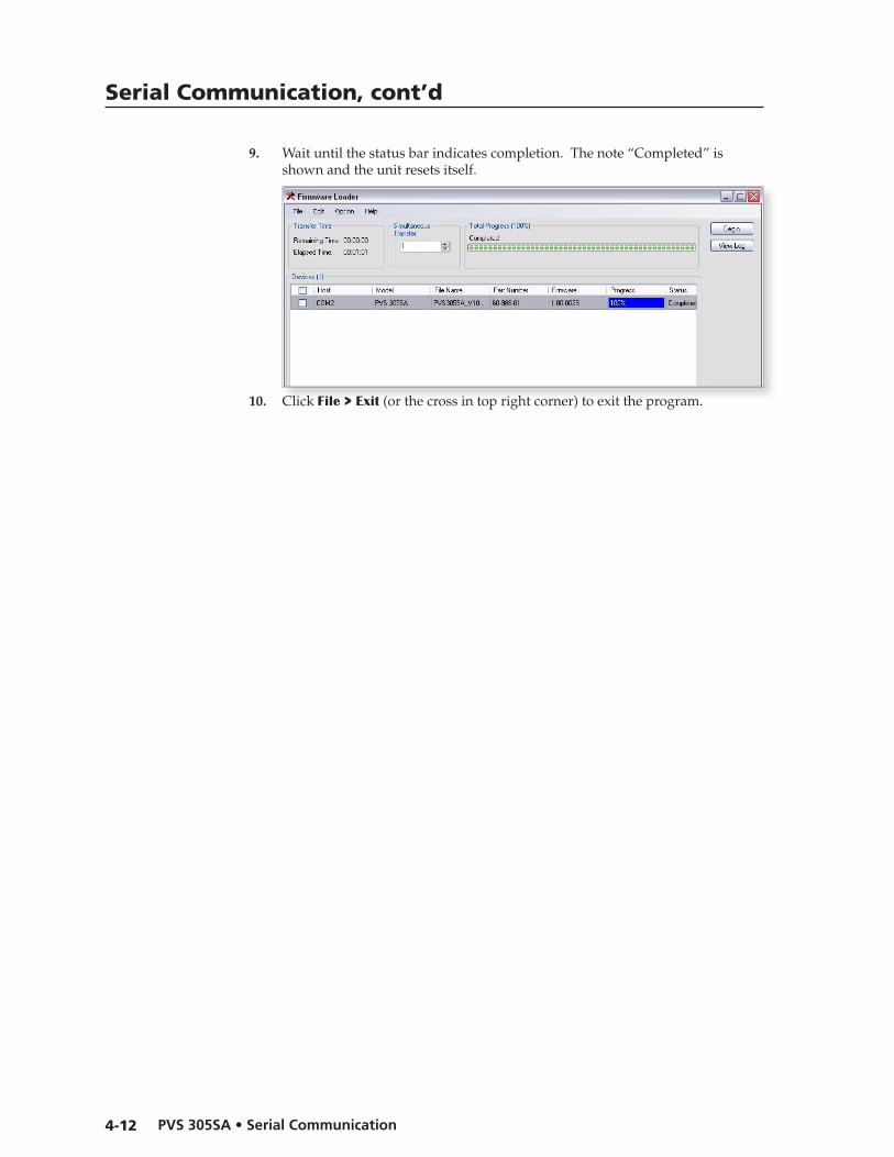
Serial Communication, cont’d
PVS 305SA • Serial Communication4-12
PREL
IMIN
ARY
PREL
IMIN
ARY
9. Wait until the status bar indicates completion. The note “Completed” is shown and the unit resets itself.
10. Click File > Exit (or the cross in top right corner) to exit the program.
PVS 305SA
5Chapter Five
Software Configuration
Configuring the Switcher

PVS 305SA Switcher • Software Configuration5-2
Software Configuration
Configuring the Switcher The PVS 305SA PoleVault Switcher can be configured using an Extron software program, either the MLS Switcher Configuration Program or the Global Configurator. These can be installed from the supplied Extron DVD, or downloaded from the Extron Web site (www.extron.com).
Installing the MediaLink Switcher Configuration programFrom the DVD
1. Insert the DVD in the appropriate drive of the PC or laptop that is connected to the switcher through the MediaLink Controller (MLC 104 IP Plus). Run the DVD and install the Extron MediaLink Switcher Configuration program.
2. Ensure the PC and the MLC 104 IP Plus are connected to the LAN and launch the MLS Configuration utility. Select the connection format (RS-232 or TCP/IP), or select the emulation mode.
N Ifthisisnotpossible,connecta2.5mmTRSconfigurationcable(part#70-335-01)tothePCandtothefrontpanelconfigurationportoftheMLC104IPPlus.
AnofflineemulationofthePVS305SAcanaidinbecomingfamiliarwiththePVS305SAbeforeconfiguringanactiveunit.
3. Once the program is running click on Help, Contents (or press F1), and follow the instructions.
From the Web site1. From the PC or laptop connected to the switcher via the MediaLink Controller
(MLC 104 IP Plus), navigate to the Extron Web site (www.extron.com).
2. On the home page click the Download tab, and at the Download Center, click on Software at the left side of the page.
3. Navigate to the MLS configuration software listing and click Download.

5-3PVS 305SA Switcher • Software Configuration
Software Configuration, cont’d
4. Complete the on-screen form and download the .exe file to the PC.
5. Launch the .exe installation wizard. Follow the on-screen prompts and install the software on the PC. This also installs a desktop icon (see image at right).
6. With the switcher connected to the PC, either through an RS-232 or LAN connection via the MediaLink Controller, click on the desktop icon to launch the MLS Configuration Utility.
7. Alternatively, select the offline emulation mode to emulate the PVS 305SA settings without connecting to the switcher.
N TheRS-232connectiontotheswitcheriseitherserialdirectorthroughtheMediaLinkController.Selectasappropriate.
8. Once the program is running and the connection is made, click on Help, Contents (or press F1), and follow the instructions.
Installing the Global Configurator
From the DVD1. Insert the DVD in the appropriate drive of the PC or laptop that is connected
to the switcher through the MediaLink Controller (MLC 104 IP Plus). Run the DVD and install the Extron Global Configurator program.
2. Once the program is installed, click on the desktop icon to open the program and select the desired start option. Click OK.
N Ifunsurewhichoptiontoselect,theViewGlobalConfiguratorHelpFileoptionopenstheHelpfile,whichisastepbystepguidetousingGlobalConfigurator.
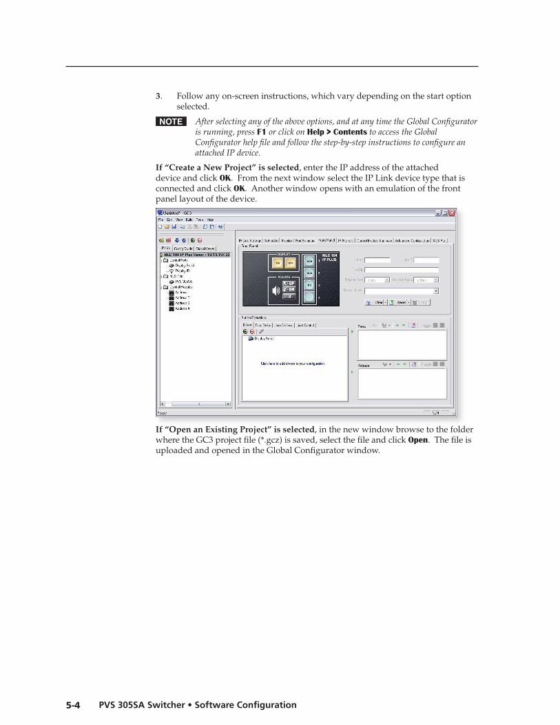
PVS 305SA Switcher • Software Configuration5-4
3. Follow any on-screen instructions, which vary depending on the start option selected.
N Afterselectinganyoftheaboveoptions,andatanytimetheGlobalConfiguratorisrunning,pressF1orclickonHelp > ContentstoaccesstheGlobalConfiguratorhelpfileandfollowthestep-by-stepinstructionstoconfigureanattachedIPdevice.
If “Create a New Project” is selected, enter the IP address of the attached device and click OK. From the next window select the IP Link device type that is connected and click OK. Another window opens with an emulation of the front panel layout of the device.
If “Open an Existing Project” is selected, in the new window browse to the folder where the GC3 project file (*.gcz) is saved, select the file and click Open. The file is uploaded and opened in the Global Configurator window.
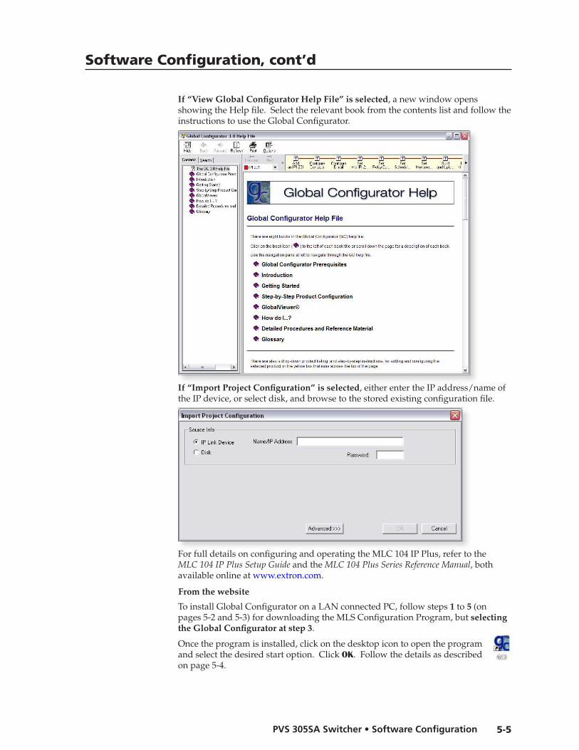
5-5PVS 305SA Switcher • Software Configuration
Software Configuration, cont’d
If “View Global Configurator Help File” is selected, a new window opens showing the Help file. Select the relevant book from the contents list and follow the instructions to use the Global Configurator.
If “Import Project Configuration” is selected, either enter the IP address/name of the IP device, or select disk, and browse to the stored existing configuration file.
For full details on configuring and operating the MLC 104 IP Plus, refer to the MLC104IPPlusSetupGuide and theMLC104PlusSeriesReferenceManual, both available online at www.extron.com.
From the website
To install Global Configurator on a LAN connected PC, follow steps 1 to 5 (on pages 5-2 and 5-3) for downloading the MLS Configuration Program, but selecting the Global Configurator at step 3.
Once the program is installed, click on the desktop icon to open the program and select the desired start option. Click OK. Follow the details as described on page 5-4.

PVS 305SA
AAppendix A
Reference Information
Specifications�
Part Numbers�, Cables�, and Acces�s�ories�

PVS 305SA Switcher • Reference Information
Reference Information
A-2
SpecificationsVideo
Gain ................................................. Unity (as a system including Extron PVT Series wallplates)Bandwidth
RGB ..................................... 200 MHz (-3 dB) @ 50' (15 m) of cableComposite video ............... 100 MHz (-3 dB)
Differential phase error ................ Composite video: 0.25° at 3.58 MHz and 4.43 MHzDifferential gain error ................... Composite video: 0.15% at 3.58 MHz and 4.43 MHzCrosstalk ......................................... -70 dB @ 5 MHzSwitching speed ............................ 1 ms (max.) from front panel, 1-2 s from remote panelCMRR .............................................. -90 dB @ 100 Hz, -70 dB @ 10 MHz
Video inputNumber/signal type ..................... Inputs 1 and 2: VGA-UXGA RGBHV, RGBS
Inputs 3 and 4 (configurable): VGA-UXGA RGBHV, RGBS, or composite videoConnectors ..................................... 4 pairs female RJ-45Nominal level ................................ As a system including Extron PVT Series wallplates:
1 Vp-p for composite video (including sync) 0.7 Vp-p for RGB
Minimum/maximum levels ........ Analog (as a system including Extron PVT Series wallplates)RGB ..................................... 0.3 V to 1.5 Vp-p with no offsetComposite video ............... 0.4 V to 2.0 Vp-p with no offset
Impedance ...................................... 75 ohms (as a system including Extron PVT Series wallplates)Horizontal frequency .................... 15 kHz to 145 kHzVertical frequency .......................... 30 Hz to 170 HzReturn loss ...................................... Composite video: <-40 dB @ 5 MHzDC offset (max. allowable)........... 1.0 V
Video outputNumber/signal type ..................... 1 VGA-UXGA RGBHV, RGBS (follows input type)
1 composite videoConnectors ..................................... 1 female 15-pin HD
1 female RCANominal level ................................ As a system including Extron PVT Series wallplates:
1 Vp-p for composite video (including sync) 0.7 Vp-p for RGB
Minimum/maximum levelsRGB ..................................... 0.3 V to 1.5 Vp-p (follows input)Composite video ............... 0.4 V to 2.0 Vp-p (follows input)
Impedance ...................................... 75 ohmsReturn loss ...................................... <-40 dB @ 5 MHzDC offset
RGB ..................................... ±5 mV, max., with input at 0 offsetComposite video ............... ±20.5 mV with input at 0 offset
SyncInput type ....................................... RGBHV, RGBS (RGB input)Output type .................................... RGBHV, RGBS (RGB output, follows input)Standards ........................................ NTSC 3.58, NTSC 4.43, PAL, SECAM (for composite video inputs and
output)Input level ...................................... 2.0 V to 5.5 Vp-p
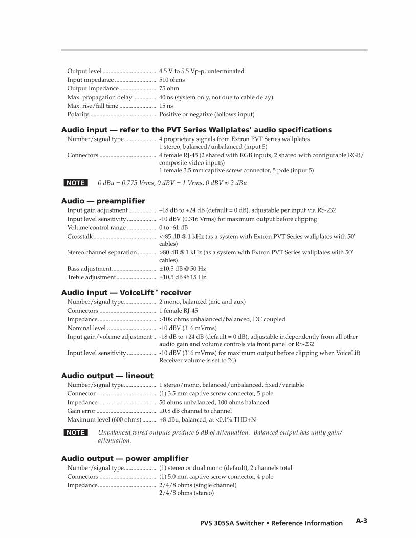
PVS 305SA Switcher • Reference Information
A-3
Output level ................................... 4.5 V to 5.5 Vp-p, unterminatedInput impedance ........................... 510 ohmsOutput impedance ........................ 75 ohmMax. propagation delay ............... 40 ns (system only, not due to cable delay)Max. rise/fall time ........................ 15 nsPolarity............................................ Positive or negative (follows input)
Audio input — refer to the PVT Series Wallplates' audio specificationsNumber/signal type ..................... 4 proprietary signals from Extron PVT Series wallplates
1 stereo, balanced/unbalanced (input 5)Connectors ..................................... 4 female RJ-45 (2 shared with RGB inputs, 2 shared with configurable RGB/
composite video inputs) 1 female 3.5 mm captive screw connector, 5 pole (input 5)
N 0dBu=0.775Vrms,0dBV=1Vrms,0dBV≈2dBu
Audio — preamplifierInput gain adjustment .................. –18 dB to +24 dB (default = 0 dB), adjustable per input via RS-232Input level sensitivity ................... -10 dBV (0.316 Vrms) for maximum output before clippingVolume control range ................... 0 to -61 dBCrosstalk ......................................... <-85 dB @ 1 kHz (as a system with Extron PVT Series wallplates with 50'
cables)Stereo channel separation ............ >80 dB @ 1 kHz (as a system with Extron PVT Series wallplates with 50'
cables)Bass adjustment ............................. ±10.5 dB @ 50 HzTreble adjustment .......................... ±10.5 dB @ 15 Hz
Audio input — VoiceLift™ receiverNumber/signal type ..................... 2 mono, balanced (mic and aux)Connectors ..................................... 1 female RJ-45Impedance ...................................... >10k ohms unbalanced/balanced, DC coupledNominal level ................................ -10 dBV (316 mVrms)Input gain/volume adjustment .. -18 dB to +24 dB (default = 0 dB), adjustable independently from all other
audio gain and volume controls via front panel or RS-232Input level sensitivity ................... -10 dBV (316 mVrms) for maximum output before clipping when VoiceLift
Receiver volume is set to 24)
Audio output — lineoutNumber/signal type ..................... 1 stereo/mono, balanced/unbalanced, fixed/variableConnector ....................................... (1) 3.5 mm captive screw connector, 5 poleImpedance ...................................... 50 ohms unbalanced, 100 ohms balancedGain error ....................................... ±0.8 dB channel to channelMaximum level (600 ohms) ......... +8 dBu, balanced, at <0.1% THD+N
N Unbalancedwiredoutputsproduce6dBofattenuation.Balancedoutputhasunitygain/attenuation.
Audio output — power amplifierNumber/signal type ..................... (1) stereo or dual mono (default), 2 channels totalConnectors ..................................... (1) 5.0 mm captive screw connector, 4 poleImpedance ...................................... 2/4/8 ohms (single channel)
2/4/8 ohms (stereo)

Reference Information, cont’d
PVS 305SA Switcher • Reference InformationA-4
Amplifier type ............................... Class DGain/volume adjustment ............ -10 dB to +10 dB (default = 0 dB), adjustable in 1 dB stepsFrequency response ...................... 20 Hz to 20 kHz, -1 dB/+3.5 dB @ 1 watt output, 8 ohm loadTHD + Noise .................................. 0.2% @ 1 kHz at nominal level (1 watt, 8 ohm load)S/N .................................................. >67 dB, 20 Hz to 20 kHz at maximum output (unweighted), 8 ohms (as a
system with Extron PVT Series wallplates with 50' cables)Continuous power output with a full load @ 20 Hz to 20 kHz, 1% THD
At 2, 4, or 8 ohms ............... 25 watts (rms) per channel (1 watt tolerance)Damping factor .............................. >75 (8 ohm load)
Control/remote — switcherSerial host control ports ............... 2 bidirectional RS-232: 1 rear panel 3.5 mm captive screw connector, 5 pole
(shared with IR control); 1 front panel 2.5 mm stereo mini jackBaud rate and protocol ................. 9600 baud, 8 data bits, 1 stop bit, no paritySerial control pin configurations . Captive screw connector: A = TX, B = RX, C = IR receive, D = GND, E = 12 VDC
2.5 mm mini stereo jack: tip = TX, ring = RX, sleeve = GNDDC volume control port ............... (1) 3.5 mm captive screw connector, 3 poleDC volume control pin configurations
1 = +10 VDC, 2 = volume/mute (variable voltage), 3 = GNDVolume control voltage range ..... 0 V (mute) to 10 V (maximum volume)Paging sensor connector .............. (1) 3.5 mm captive screw connector, 2 poleProgram control ............................. Extron control/configuration program for Windows®
Extron Simple Instruction Set (SIS™)
GeneralExternal power supply ................. 100 VAC to 240 VAC, 50-60 Hz, external; to 12 VDC, 5 A, regulatedPower input requirements ........... 12 VDC, 5 ATemperature/humidity ................ Storage: -40 to +158 °F (-40 to +70 °C) / 10% to 90%, noncondensing
Operating: +32 to +122 °F (0 to +50 °C) / 10% to 90%, noncondensingCooling ........................................... Convection, vents on sidesMounting
Rack mount ........................ Yes, with optional 1U rack shelfFurniture mount ................ Yes, with optional mini under-desk mounting kitPole mount ......................... Yes, with optional pole mounting kit
Enclosure type ............................... MetalEnclosure dimensions ................... 1.7" H x 8.7" W x 3.0" D (1U high, half rack wide)
(approximately 4.3 cm H x 22.1 cm W x 7.6 cm D)Product weight .............................. 2.5 lbs (1.1 kg), plus power supply (0.9 lbs [0.4 kg])Shipping weight ............................ 5 lbs (2.3 kg)Vibration ......................................... ISTA 1A in carton (International Safe Transit Association)Regulatory compliance
Safety ................................... CE, c-UL, ULUL rated for use in plenum airspaces: meets UL 2043 for heat and smoke release, excluding the power supply; meets UL 60065 for safety.
EMI/EMC .......................... CE, C-tick, FCC Class B, ICES, VCCIEnvironmental ................... Complies with the appropriate requirements of RoHS, WEEE
MTBF ............................................... 30,000 hoursWarranty ......................................... 3 years parts and labor
N Allnominallevelsareat±10%.
N Specificationsaresubjecttochangewithoutnotice.

PVS 305SA Switcher • Reference Information
A-5
Part Numbers, Cables, and Accessories
Included parts
Included part Replacement part number
PVS 305SA 60-986-01
US style IEC power cord
Power supply
PVS305SASetupGuide
CablesN Forsignalcablerequirements,pleasecheckthelatestExtroncatalogorvisit
www.extron.comforacomprehensivelist.ThecablelistedbelowisforfrontpanelRS-232use.
Accessory Part number
CFG 9-pin D female to 2.5 mm TRS configuration cable 70-335-01

PVS 305SA
BAppendix B
Speaker Configuration
Wiring Information

PVS 305SA Switcher • Appendix B
Appendix B
B-2
Terminating the speaker cableTo terminate the cable, strip the end of the cable 0.2 inch (5 mm) and secure the wires into the supplied 4-pole captive screw connector.
Speaker ConfigurationWhen setting up a speaker configuration, the correct speaker impedance loading must be observed.
N Bydefault,theamplifierissetfordualmonooutput.UsetheExtronsoftwareorSIS(Extron SpecialInstructionSet)commandstochangethesettingtostereoifdesired.
PVS SwitcherRear Panel
Speaker 1 Speaker 2
L R
4/8Ohms
AMPLIFIED OUTPUTS
4-pole CaptiveScrew Connector
Audio outputto speakers
8 Ohm LoadStereo R–
Stereo R+
Stereo L–
L R
8 OhmsAMPLIFIED OUTPUTS
Stereo L+
Stereo or dual mono output using parallel speaker wiring
Stereo output Dual mono output
8 Ohm Load
L R
8 OhmsAMPLIFIED OUTPUTS
Mono –
Mono +
Mono –
Mono +
4 Ohm Total Load4 Ohm Total Load
Two 8 ohm speakers wired in parallel equal a 4 ohm load.
L R
2/4/8 OhmsAMPLIFIED OUTPUTS
Mono –or
Stereo R-
8ohms
8 ohms
Mono +or
Stereo R+
Mono –or
Stereo L-
Mono +or
Stereo L+
8ohms
8 ohms
Speaker wire color To PVS 305SA terminal (Left and Right)
Red Positive (+)
Black Negative (-)
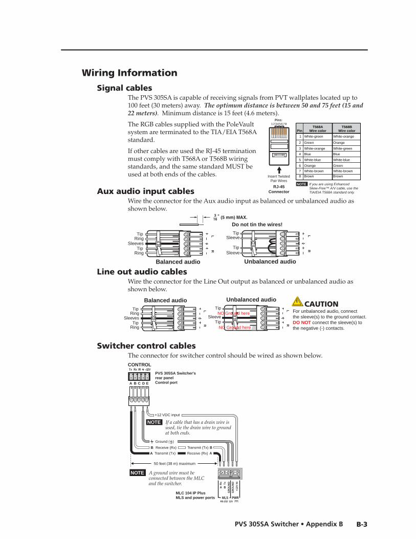
PVS 305SA Switcher • Appendix B
B-3
Wiring Information
Signal cablesThe PVS 305SA is capable of receiving signals from PVT wallplates located up to 100 feet (30 meters) away. The optimum distance is between 50 and 75 feet (15 and 22 meters). Minimum distance is 15 feet (4.6 meters).
The RGB cables supplied with the PoleVault system are terminated to the TIA/EIA T568A standard.
If other cables are used the RJ-45 termination must comply with T568A or T568B wiring standards, and the same standard MUST be used at both ends of the cables.
Aux audio input cablesWire the connector for the Aux audio input as balanced or unbalanced audio as shown below.
Balanced audio
TipRing
TipRing
LR
Sleeves
Do not tin the wires!
Unbalanced audio
TipSleeve
SleeveTip
LR
Line out audio cablesWire the connector for the Line Out output as balanced or unbalanced audio as shown below.
Balanced audioTip
Ring
TipRing
LR
Sleeves
Unbalanced audioTip
SleeveTip
LR
CAUTIONFor unbalanced audio, connectthe sleeve(s) to the ground contact. DO NOT connect the sleeve(s) tothe negative (-) contacts.NO Ground here
NO Ground here
Switcher control cablesThe connector for switcher control should be wired as shown below.CONTROL
A B C
PVS 305SA Switcher'srear panelControl port
NOTE A ground wire must be connected between the MLC and the switcher.
MLC 104 IP Plus MLS and power ports
NOTE If a cable that has a drain wire is used, tie the drain wire to ground at both ends.
D E
Tx Rx IR +12 V
RS-232 12VMLS PWR
A B
Rx
Tx
GR
OU
ND
GR
OU
ND
+12V
IN
Ground ( )
Transmit (Tx)
B Receive (Rx)
A
Transmit (Tx)
Receive (Rx)
B
A
+12 VDC input
50 feet (38 m) maximum
12345678
RJ-45Connector
Insert TwistedPair Wires
Pins:
Pin
1
2
3
4
5
6
7
8
Wire color
White-green
Green
White-orange
Blue
White-blue
Orange
White-brown
Brown
Wire colorT568A T568B
White-orange
Orange
White-green
Blue
White-blue
Green
White-brown
Brown
NOTE If you are using Enhanced Skew-Free™ A/V cable, use the TIA/EIA T568A standard only.
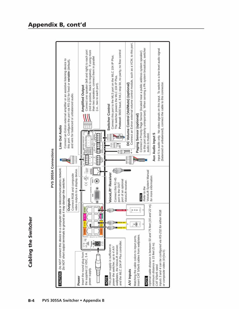
Appendix B, cont’d
PVS 305SA Switcher • Appendix BB-4
LR
LR
LR
AU
X A
UD
IOIN
PU
T 5
LIN
E O
UT
VOIC
ELI
FTR
EC
EIV
ER
PAGI
NGSE
NSOR
DO N
OTGR
OUND
OR S
HORT
SPEA
KER
OUTP
UTS
1B R
GB
1A R
GB
2B R
GB
2A R
GB
3B R
GB
/VID
EO
4B R
GB
/VID
EO
3A R
GB
4A R
GB
I N P U T S
RS
-232
ML
C/IR
2/4/
8O
hms
CLA
SS
2 W
IRIN
G
AM
PL
IFIE
D A
UD
IO O
UT
VO
L/M
UT
E
Tx
Rx
IR12
V10
V50
mA
PO
WE
R
US
LIST
ED
17TT
AU
DIO
/VID
EOA
PPA
RAT
US
®
RG
BV
IDE
OO
UT
PU
TS
CO
NT
RO
L
N15
779
12V
5A M
AX
Con
nect
this
por
t to
the
MLS
por
t on
the
MLC
104
IP P
lus.
The
sw
itche
r po
wer
s th
e M
LC 1
04 IP
Plu
s.
Inse
rt th
e ro
und
plug
from
the
supp
lied
12 V
DC
, 5 A
pow
er s
uppl
y.
Po
wer
Con
nect
RG
B a
nd c
ompo
site
vi
deo
outp
uts
to a
dis
play
dev
ice.
N Opt
imal
cab
le d
ista
nce
is b
etw
een
50 a
nd 7
5 fe
et (
15 a
nd 2
2 m
),m
inim
um d
ista
nce
is 1
5 fe
et (
5 m
). C
AT 5
/5e/
6 ra
ted.
In
puts
3 a
nd 4
can
be
conf
igur
ed v
ia R
S-2
32 fo
r ei
ther
RG
Bor
com
posi
te v
ideo
(d
efau
lt).
C
Do
NO
T c
onne
ct th
is d
evic
e to
a c
ompu
ter
data
or
tele
com
mun
icat
ions
net
wor
k.
Do
NO
T s
hort
out
put t
erm
inal
s to
gro
und
as it
may
dam
age
the
switc
her.
Sw
itch
er C
on
tro
l
Pro
toco
l: 9
600
baud
, 8 b
it,1
stop
bit,
no
parit
y, n
o flo
w c
ontr
ol
Con
nect
one
spe
aker
(le
ft an
d rig
ht)
to e
ach
port
(red
to p
ositi
ve, b
lack
to n
egat
ive)
. If
usin
g m
ore
than
two
spea
kers
, con
nect
them
in p
aral
lel
(i.e.
, tw
o to
eac
h po
rt).
Am
plif
ied
Ou
tpu
t
10V
Con
nect
a P
riorit
y P
age
Sen
sor
(loca
ted
near
a p
ublic
add
ress
sys
tem
spe
aker
) to
this
por
t (po
larit
y un
impo
rtan
t).
Whe
n se
nsin
g a
PA s
yste
m b
road
cast
, sw
itche
r au
dio
is m
uted
.
Pag
ing
Sen
sor
(op
tio
nal
)
N Thi
s po
wer
sup
ply
is s
uffic
ient
topo
wer
the
switc
her,
up to
4 A
/V
wal
lpla
tes,
the
Voi
ceLi
ft re
ceiv
er,
and
the
MLC
104
IP P
lus
cont
rolle
r.
4B VIDEO
Mat
chin
g th
e ca
ble
colo
rs to
inpu
t por
ts,
inse
rt C
AT 5
/5e/
6 ca
bles
from
wal
lpla
tes.
AU
DIO
IN L R
VID
EO
IN
A/V
Inp
uts
2A RGB
2B RGB
CO
MP
UT
ER
IN
AU
DIO
IN
Con
nect
an
Ext
ron
exte
rnal
am
plifi
er o
r an
ass
istiv
e lis
teni
ng d
evic
e to
th
is p
ort.
Con
figur
e th
e po
rt v
ia R
S-2
32 fo
r fix
ed o
r va
riab
le (
defa
ult)
,an
d w
ire fo
r ba
lanc
ed o
r un
bala
nced
aud
io.
Con
nect
an
Ext
ron
exte
rnal
vol
ume
cont
rol m
odul
e, s
uch
as a
VC
M, t
o th
is p
ort.
DC
Vo
lum
e C
on
tro
l (Vo
l/Mu
te)
(op
tio
nal
)
N15
779
VOIC
US
LIST
ED
17TT
AU
DA
PP®
Con
nect
this
RJ-
45po
rt to
the
OU
T
port
of a
n op
tiona
lV
oice
Lift
rece
iver
.
Voic
eLif
t® R
ecei
ver
N Ref
er to
the
Voi
ceLi
ft S
yste
m M
anua
lfo
r m
ore
info
rmat
ion.
Inpu
t 5 is
aud
io o
nly.
No
vide
o si
gnal
s on
this
inpu
t. T
o sw
itch
to a
line
-leve
l aud
io s
igna
l(b
alan
ced
or u
nbal
ance
d), c
onne
ct th
e ca
ble
to th
is c
onne
ctor
.
Au
x A
ud
io In
pu
t 5
Lin
e O
ut
Au
dio
1A R
GB
2A R
GB
3A R
GB
4A R
GB
2A R
GB
1A R
GB
4A R
GB
3A R
GB
1B R
GB
2B R
GB
3B R
GB
/VID
EO
4B R
GB
/VID
EO
1B R
GB
2B R
GB
RG
BV
IDE
O3B
RG
BV
IDE
O4B
PV
S 3
05S
A C
on
nec
tio
ns
Ou
tpu
ts
Cab
lin
g t
he S
wit
cher
Extron WarrantyExtron® Electronics warrants this product against defects in materials and workmanship for a period of three years from the date of purchase. In the event of malfunction during the warranty period attributable directly to faulty workmanship and/or materials, Extron Electronics will, at its option, repair or replace said products or components, to whatever extent it shall deem necessary to restore said product to proper operating condition, provided that it is returned within the warranty period, with proof of purchase and description of malfunction to:
USA, Canada, South America, and Central America: Extron Electronics1001 East Ball Road Anaheim, CA 92805 U.S.A.
Japan: Extron Electronics, Japan Kyodo Building, 16 Ichibancho Chiyoda-ku, Tokyo 102-0082 Japan
Europe, Africa, and the Middle East: Extron Europe Hanzeboulevard 10 3825 PH Amersfoort The Netherlands
China: Extron China 686 Ronghua Road Songjiang District Shanghai 201611 China
Asia: Extron Asia 135 Joo Seng Road, #04-01 PM Industrial Bldg. Singapore 368363 Singapore
Middle East: Extron Middle East Dubai Airport Free Zone F12, PO Box 293666 United Arab Emirates, Dubai
This Limited Warranty does not apply if the fault has been caused by misuse, improper handling care, electrical or mechanical abuse, abnormal operating conditions, or any modifications that were not authorized by Extron, being made to the product.
If it has been determined that the product is defective, please call Extron and ask for an Applications Engineer at (714) 491-1500 (USA), 31.33.453.4040 (Europe), 65.383.4400 (Asia), or 81.3.3511.7655 (Japan) to receive an RA# (Return Authorization number). This will begin the repair process as quickly as possible.
Units must be returned insured, with shipping charges prepaid. If not insured, you assume the risk of loss or damage during shipment. Returned units must include the serial number and a description of the problem, as well as the name of the person to contact in case there are any questions.
Extron Electronics makes no further warranties either expressed or implied with respect to the product and its quality, performance, merchantability, or fitness for any particular use. In no event will Extron Electronics be liable for direct, indirect, or consequential damages resulting from any defect in this product even if Extron Electronics has been advised of such damage.
Please note that laws vary from state to state and country to country, and that some provisions of this warranty may not apply to you.

Extron USA - West Headquarters
+800.633.9876Inside USA / Canada Only
+1.714.491.1500+1.714.491.1517 FAX
Extron USA - East
+800.633.9876Inside USA / Canada Only
+1.919.863.1794+1.919.863.1797 FAX
Extron Europe
+800.3987.6673Inside Europe Only
+31.33.453.4040+31.33.453.4050 FAX
Extron Asia
+800.7339.8766Inside Asia Only
+65.6383.4400+65.6383.4664 FAX
Extron Japan
+81.3.3511.7655+81.3.3511.7656 FAX
Extron China
+400.883.1568Inside China Only
+86.21.3760.1568+86.21.3760.1566 FAX
Extron Middle East
+971.4.2991800+971.4.2991880 FAX
© 2010 Extron Electronics. All rights reserved.