PVC/Nylon and XLPE Insulated Tray Cables - Nexans Cable s pass UL 1685 and IEEE 383 vertical tray...
30
ULTREX ® PVC/Nylon and XLPE Insulated Tray Cables
-
Upload
duongnguyet -
Category
Documents
-
view
216 -
download
1
Transcript of PVC/Nylon and XLPE Insulated Tray Cables - Nexans Cable s pass UL 1685 and IEEE 383 vertical tray...

ULTREX®PVC/Nylon and XLPE Insulated Tray Cables

1-866-663-9267
1
UL Type TC, 600 VoltPower and Control Cables
Introduction . . . . . . . . . . . . . . . . . . . . . . . . . . . . . . . . . . . . . . . . . 2 ULTREX ® VN
PVC/Nylon Insulated, PVC Jacketed
Applications and Description . . . . . . . . . . . . . . . . . . . . . . . . . . . . . 318 AWG Unshielded . . . . . . . . . . . . . . . . . . . . . . . . . . . . . . . . . . 418 AWG Shielded . . . . . . . . . . . . . . . . . . . . . . . . . . . . . . . . . . . . 516 AWG Unshielded . . . . . . . . . . . . . . . . . . . . . . . . . . . . . . . . . . 616 AWG Shielded . . . . . . . . . . . . . . . . . . . . . . . . . . . . . . . . . . . . 714 AWG Unshielded . . . . . . . . . . . . . . . . . . . . . . . . . . . . . . . . . . 814 AWG Shielded . . . . . . . . . . . . . . . . . . . . . . . . . . . . . . . . . . . . 912 AWG Unshielded . . . . . . . . . . . . . . . . . . . . . . . . . . . . . . . . . 1012 AWG Shielded . . . . . . . . . . . . . . . . . . . . . . . . . . . . . . . . . . . 1110 AWG Unshielded . . . . . . . . . . . . . . . . . . . . . . . . . . . . . . . . . 1210 AWG Shielded . . . . . . . . . . . . . . . . . . . . . . . . . . . . . . . . . . . 133 Conductors with Ground . . . . . . . . . . . . . . . . . . . . . . . . . . . . . 144 Conductors with Ground . . . . . . . . . . . . . . . . . . . . . . . . . . . . . 15Dupont — Construction . . . . . . . . . . . . . . . . . . . . . . . . . . . . . . . . 16Dupont Composite Construction . . . . . . . . . . . . . . . . . . . . . . . . . . 17Dow Composite Construction. . . . . . . . . . . . . . . . . . . . . . . . . . . . 18Composite Cables . . . . . . . . . . . . . . . . . . . . . . . . . . . . . . . . . . . 19
ULTREX ® XL - XLTC
XLP Insulated, PVC Jacketed
Applications and Description . . . . . . . . . . . . . . . . . . . . . . . . . . . . 2014 AWG Unshielded . . . . . . . . . . . . . . . . . . . . . . . . . . . . . . . . . 2112 AWG Unshielded . . . . . . . . . . . . . . . . . . . . . . . . . . . . . . . . . 2210 AWG Unshielded . . . . . . . . . . . . . . . . . . . . . . . . . . . . . . . . . 233 Conductors with Ground . . . . . . . . . . . . . . . . . . . . . . . . . . . . . 244 Conductors with Ground . . . . . . . . . . . . . . . . . . . . . . . . . . . . . 25
Conductor or Phase Identification . . . . . . . . . . . . . . . . . . . . . . 26 Notices. . . . . . . . . . . . . . . . . . . . . . . . . . . . . . . . . . . . . . . . . . . . 27
ULTREX ® Tray Cables®
®
®

1-866-663-9267
2
Introduction
Nexans brings energy to life through an extensive range of cables and cabling solutions that deliver impeccable performance for our customers worldwide. With more than a century of experience in cable manufacturing, you can rely on the quality of Nexans’ products. Our teams are committed to a partnership approach that supports customers in four main business areas: Power transmission and distribution (Submarine and Land), Energy resources (Oil & Gas, Mining and Renewables), Transportation (Road, Rail, Air, Sea) and Building (Commercial, Residential, Industrial and Data Centers).
Nexans’ strategy is founded on continuous innovation in products, solutions and services, employee development, customer training and the introduction of safe, low-environmental-impact industrial processes. In 2013, Nexans became the first cable manufacturer to create a Foundation to introduce sustained initiatives for access to energy for disadvantaged communities worldwide.
This catalog has been prepared for the convenience of those using electrical conductors in industrial applications. The information included in the many tabulations will be of particular value to the architect, engineer, electrician, and layperson alike. For your convenience, we have referenced applicable Articles and Tables from the NEC.
All the cables in this catalog are LEAD FREE. This indicates that the Nexans cable components have less than 300 ppm of lead, which is well below the 1000 ppm level indicated in RoHS (restriction of hazardous substances) regulations and below the level requiring labeling by California Proposition #65.

1-866-663-9267
3
Applications
Nexans 600 V ULTREX® VN Tray Cables are listed as type TC or TC-ER under UL 1277 Electrical Power and Control Cables. These cables may be installed in wet or dry locations; in cable trays, raceways and open air; and are suitable for exposure to weather, direct burial and for Class I, Div. 2 (also Zone 2) and Class II, Div. 2 hazardous locations per NEC. Cables with 3 or more conductors are UL listed for exposed runs (ER) when installed in accordance with NEC Article 336.10(7).
Construction
Conductor: bare, annealed copper conforming to ASTM B3 and Class B stranded in accordance to ASTM B8, from 18 AWG to 500 kcmil. Compressed copper for 14 AWG through 500 kcmil.
Insulation: flame-retardant PVC/Nylon type THHN/THWN-2 per UL 83 for sizes 14 AWG to 500 kcmil and type TFN per UL 66 for 18 AWG and 16 AWG.
Assembly :Non-shielded: cables with 3 or more conductors are cabled in concentric layers with interstices filled with suitable fillers, as required. Two-conductor cables are supplied in a flat/parallel configuration. Ground wires are sized as required by UL 1277 (refer to the applicable product tables for the standard sizes provided). Sizes 14 AWG to 6 AWG have an insulated green ground wire. Sizes 4 AWG and larger have a bare ground wire. Where necessary, a binder tape of synthetic material assembles the core in a tight circular configuration.Shielded : cabled in concentric layers with interstices filled with suitable fillers as required. A helically wrapped aluminum tape, with synthetic backing, gives 100% shielding. A tinned copper drain wire is placed in contact with the aluminum side of the tape, to lower the resistance and to assist in the termination of the shield.
PVC/Nylon Type TC or TC-ER 600 VoltPower and Control CableTemperature rating of 90 °C dry / wet rated
Jacket: UL listed sunlight and moisture resistant, black, flame retardant polyvinyl
chloride (PVC) material meeting the requirements of UL 1277. A Nylon ripcord is included for ease of jacket removal. Jacket surface is printed with required UL / NEC code information and sequential footage markings.
Sample Print Legend: NEXANS-C ULTREX-VN 600V TC-ER 3/C-12AWG THHN/THWN-2 SUN RES DIR BUR (UL) ROHS MFG DATE
Conductor Identification(See page 26 of this catalog)
18 AWG to 10 AWG: Color coded per Method #1-E2 per ICEA S-73-532
8 AWG to 500 kcmil: black with number coding per Method 4 of ICEA S-73-532
Composite
Power:Black with number coding per Method 4 of ICEA S-73-532Control:Color coded per Method #1-E2 per ICEA S-73-532
Specifications
• Meets UL 1277: Power and Control Tray Cables with Optional Fiber Members.
• Meets UL 83: Thermoplastic-Insulated Wires and Cables for 14 AWG and larger.• Meets UL 66: Fixture Wire for 18 AWG
and 16 AWG.• Meets ICEA S-95-658, NEMA Publication
No. WC-70: Non-Shielded Power Cables rated 2000 volts or Less for the Distribution of Electrical Energy.
• Dupont constructions meet Dupont Engineering Specification SE33.4B: “600-Volt Multiconductor Type TC Cable; THWN-THHN or TFN Insulated and with Vinyl Jacket”
Product Features
• UL approved cables Type TC or TC-ER, 600 V. • UL approved insulated conductors.• Cables pass UL 1685 and IEEE 383 vertical
tray fire tests at 70,000 BTU/hr.• Cables are UL listed to IEEE 1202 and FT4
70,000 BTU/hr flame test.
• For use in power, lighting, control and signalcircuits.
• Can be used within industrial establishmentswhere serviced by qualified personnel and not subject to physical damage.
• Can operate at continuous temperatures of 90°°C dry and wet.
• Can be used In Class I Division 2 and Class II Division 2 Hazardous Locations and Intrinsically Safe applications as permitted by NEC Articles 392, 501, 502, 503, and 505.*
• As indicated in UL 1277: The overall jackets of these cables are a “gas/vapor tight continuous sheath” as discussed in NEC Article 501.15(D) & (E).*
• For use in cable trays, raceways, conduits, or for aerial applications where installed with a messenger.
• For Direct Burial applications.• Cables of 2 or more conductors (plus a
ground conductor) are UL listed for Exposed Run (ER) per NEC Article 336.10(7):1) Cables sized from 18 AWG to 6 AWG
have an insulated ground conductor.2) Cables sized 4 AWG and larger have a
bare ground conductor.• As permitted in NEC Article 725 for Class
• As permitted for non-power-limited alarmcircuits as defined in NEC Article 760.
• Lead free and RoHS compliant• Sunlight and moisture resistant
Options
The following constructions can be provided on special orders: • Cables sized 4 AWG and larger with an
insulated ground conductor• Dow Construction• DuPont Construction• Composite Cable Construction• Insulated or bare ground wires• Different conductor methods
* Use in hazardous locations: Please note that no investigation of these cables has been performed regarding the transmission of gases or vapors through the core. When these cables are used in hazardous locations they should be sealed properly as required by the NEC.
ULTREX ® VN®
°
• Cold bend of –25°C per UL 1277.
1 circuits.
1-866-663-9267
4
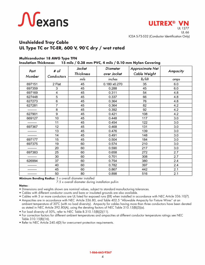
Unshielded Tray CableUL Type TC or TC-ER, 600 V, 90 C dry / wet rated
Multiconductor 18 AWG Type TFNInsulation Thickness: 15 mils / 0.38 mm PVC, 4 mils / 0.10 mm Nylon Covering
Mininum Bending Radius: 5 x overall diameter installed 7.5 x overall diameter during installation pull-in.Notes : • Dimensions and weights shown are nominal values, subject to standard manufacturing tolerances. • Cables with different conductor counts and bare or insulated grounds are also available.• Cables with 3 or more conductors are UL listed for exposed runs (ER) when installed in accordance with NEC Article 336.10(7).• Ampacities are in accordance with NEC Article 336.80, and Table 402.5 “Allowable Ampacity for Fixture Wires” at an
ambient temperature of 30°C (with no load diversity). Ampacity for cables having more than three conductors have been derated as stated in NEC Article 392.80(A), using the derating factors of NEC Table 310.15(B)(3)(a).
• For load diversity of 50%, refer to NEC Table B.310.15(B)(2)(11). • For correction factors for different ambient temperatures and ampacities at different conductor temperature ratings see NEC Table 310.15(B)(16).
• Refer to NEC Article 240.4(D) for overcurrent protection requirements.
ULTREX® VNUL 1277
UL 66 ICEA S-73-532 (Conductor Identification Only)
®
°
°
Jacket
Thickness
Diameter
over Jacket
Approximate Net
Cable WeightAmpacity
mils inches lb/kft amps697151 2 Flat 45 0.180 x0.270 35 6.0697359 3 45 0.288 45 6.0697169 4 45 0.311 54 4.8627448 5 45 0.337 66 4.8627273 6 45 0.364 76 4.8627281 7 45 0.364 82 4.2-------- 8 45 0.392 92 4.2627901 9 45 0.421 108 4.2669127 10 45 0.448 117 3.0-------- 11 45 0.454 122 3.0697367 12 45 0.468 131 3.0-------- 13 45 0.476 139 3.0-------- 14 45 0.491 148 3.0697177 15 45 0.504 184 3.0697375 19 60 0.574 210 3.0-------- 20 60 0.590 217 3.0697383 25 60 0.658 272 2.7-------- 30 60 0.701 308 2.7626994 37 60 0.754 380 2.4-------- 40 60 0.782 397 2.4-------- 45 60 0.867 442 2.1-------- 50 80 0.898 516 2.1
Part
Number
# of
Conductors

1-866-663-9267
5
UL 1277 UL 66
Mininum Bending Radius: 5 x overall diameter installed 7.5 x overall diameter during installation pull-in.
Notes : • Dimensions and weights shown are nominal values, subject to standard manufacturing tolerances. • Cables with different conductor counts and bare or insulated grounds are also available.• Cables with 3 or more conductors are UL listed for exposed runs (ER) when installed in accordance with NEC Article 336.10(7). • Ampacities are in accordance with NEC Article 336.80, and Table 402.5 “Allowable Ampacity for Fixture Wires” at an
ambient temperature of 30°C (with no load diversity). Ampacity for cables having more than three conductors have been derated as stated in NEC Article 392.80(A), using the derating factors of NEC Table 310.15(B)(3)(a).
• For load diversity of 50%, refer to NEC Table B.310.15(B)(2)(11).• For correction factors for different ambient temperatures and ampacities at different conductor temperature ratings see NEC Table 310.15(B)(16).
• Refer to NEC Article 240.4(D) for overcurrent protection requirements.
Shielded Tray CableUL Type TC or TC-ER, 600 V, 90 C dry / wet rated
Multiconductor 18 AWG Type TFNInsulation Thickness: 15 mils / 0.38 mm PVC, 4 mils / 0.10 mm Nylon CoveringDrain Wire: 20 AWG (7w) Tinned Copper
ULTREX® VN®
°
°
ICEA S-73-532 (Conductor Identification Only)
Jacket
Thickness
Diameter
over Jacket
Approximate Net
Cable WeightAmpacity
mils inches lb/kft amps697409 2 45 0.280 38 6.0697417 3 45 0.294 49 6.0627059 4 45 0.317 58 4.8-------- 5 45 0.343 73 4.8627067 6 45 0.370 82 4.8674689 7 45 0.370 87 4.2627521 8 45 0.404 98 4.2-------- 9 45 0.433 112 4.2674697 10 45 0.460 127 3.0-------- 11 45 0.466 130 3.0697458 12 45 0.480 136 3.0-------- 13 45 0.488 144 3.0-------- 14 45 0.503 153 3.0-------- 15 45 0.516 165 3.0-------- 19 60 0.586 215 3.0-------- 20 60 0.602 272 3.0675751 25 60 0.670 280 2.7-------- 30 60 0.713 318 2.7-------- 37 60 0.766 390 2.4-------- 40 60 0.794 407 2.4-------- 45 80 0.879 452 2.1-------- 50 80 0.910 526 2.1
Part
Number
# of
Conductors

1-866-663-9267
6
UL 1277 UL 66
Mininum Bending Radius: 5 x overall diameter installed 7.5 x overall diameter during installation pull-in.
Notes : • Dimensions and weights shown are nominal values, subject to standard manufacturing tolerances. • Cables with different conductor counts and bare or insulated grounds are also available.• Cables with 3 or more conductors are UL listed for exposed runs (ER) when installed in accordance with NEC Article 336.10(7). • Ampacities are in accordance with NEC Article 336.80, and Table 402.5 “Allowable Ampacity for Fixture Wires” at an
ambient temperature of 30°C (with no load diversity). Ampacity for cables having more than three conductors have been derated as stated in NEC Article 392.80(A), using the derating factors of NEC Table 310.15(B)(3)(a).
• For load diversity of 50%, refer to NEC Table B.310.15(B)(2)(11). • For correction factors for different ambient temperatures and ampacities at different conductor temperature ratings see NEC
Table 310.15(B)(16).• Refer to NEC Article 240.4(D) for overcurrent protection requirements.
Unshielded Tray CableUL Type TC or TC-ER, 600 V, 90 C dry / wet rated
Multiconductor 16 AWG Type TFNInsulation Thickness: 15 mils / 0.38 mm PVC, 4 mils / 0.10 mm Nylon Covering
ULTREX VN®
°
°
ICEA S-73-532 (Conductor Identification Only)
Jacket
Thickness
Diameter
over Jacket
Approximate Net
Cable WeightAmpacity
mils inches lb/kft amps697045 2 Flat 45 0.190 x0.290 45 8.0697052 3 45 0.306 59 8.0631010 4 45 0.330 71 6.4697342 5 45 0.360 86 6.4697060 6 45 0.390 100 6.4697078 7 45 0.390 110 5.6697086 8 45 0.425 128 5.6697094 9 45 0.452 141 5.6697102 10 45 0.480 157 4.0-------- 11 45 0.486 165 4.0697110 12 45 0.505 179 4.0-------- 13 45 0.510 205 4.0-------- 14 60 0.556 219 4.0671784 15 60 0.570 232 4.0697128 16 60 0.594 240 4.0697136 19 60 0.610 283 4.0627463 20 60 0.640 300 4.0697144 25 60 0.715 367 3.6697896 30 60 0.765 430 3.6697664 37 80 0.864 548 3.2-------- 40 80 0.893 584 3.2-------- 45 80 0.943 649 2.8627471 50 80 0.980 689 2.8
Part
Number
# of
Conductors

1-866-663-9267
7
UL 1277 UL 66
Mininum Bending Radius: 5 x overall diameter installed 7.5 x overall diameter during installation pull-in.
Notes : • Dimensions and weights shown are nominal values, subject to standard manufacturing tolerances. • Cables with different conductor counts and bare or insulated grounds are also available.• Cables with 3 or more conductors are UL listed for exposed runs (ER) when installed in accordance with NEC Article 336.10(7). • Ampacities are in accordance with NEC Article 336.80, and Table 402.5 “Allowable Ampacity for Fixture Wires” at an
ambient temperature of 30°C (with no load diversity). Ampacity for cables having more than three conductors have been derated as stated in NEC Article 392.80(A), using the derating factors of NEC Table 310.15(B)(3)(a).
• For load diversity of 50%, refer to NEC Table B.310.15(B)(2)(11). • For correction factors for different ambient temperatures and ampacities at different conductor temperature ratings see NEC
Table 310.15(B)(16).• Refer to NEC Article 240.4(D) for overcurrent protection requirements.
Shielded Tray CableUL Type TC or TC-ER, 600 V, 90 C dry / wet rated
Multiconductor 16 AWG Type TFN Insulation Thickness: 15 mils / 0.38 mm PVC, 4 mils / 0.10 mm Nylon CoveringDrain Wire: 18 AWG (7w) Tinned Copper
ULTREX® VN®
°
°
ICEA S-73-532 (Conductor Identification Only)
Jacket
Thickness
Diameter
over Jacket
Approximate Net
Cable WeightAmpacity
mils inches lb/kft amps697466 2 45 0.298 51 8.0627091 3 45 0.314 67 8.0627083 4 45 0.339 80 6.4631127 5 45 0.368 96 6.4687491 6 45 0.398 111 6.4631135 7 45 0.398 120 5.6-------- 8 45 0.435 136 5.6-------- 9 45 0.467 149 5.6-------- 10 45 0.497 165 4.0-------- 11 45 0.504 173 4.0697441 12 60 0.549 187 4.0-------- 13 60 0.558 213 4.0-------- 14 60 0.575 229 4.0-------- 15 60 0.589 242 4.0627109 19 60 0.634 301 4.0-------- 20 60 0.652 310 4.0-------- 25 60 0.727 377 3.6-------- 30 60 0.775 440 3.6-------- 37 80 0.885 568 3.2-------- 40 80 0.905 604 3.2-------- 45 80 0.955 669 2.8-------- 50 80 0.989 743 2.8
Part
Number
# of
Conductors

1-866-663-9267
8
UL 1277 UL 83
Mininum Bending Radius: 5 x overall diameter installed 7.5 x overall diameter during installation pull-in.Notes : • Dimensions and weights shown are nominal values, subject to standard manufacturing tolerances. • Cables with different conductor counts and bare or insulated grounds are also available.• Cables with 3 or more conductors are UL listed for exposed runs (ER) when installed in accordance with NEC Article 336.10(7). • Ampacities are in accordance with NEC Table 310.15(B)(16) for conductors in a raceway or direct buried at 30°C ambient
temperature and 90°C rated conductors. Ampacities for cables having more than three conductors have been derated per NEC
• For load diversity of 50%, refer to NEC Table B.310.15(B)(2)(11). • For correction factors for different ambient temperatures and ampacities at different conductor temperature ratings see NEC
Table 310.15(B)(16).• NEC Article 240.4(D) requires that overcurrent protection not exceed 15 amperes for 14 AWG copper conducts after any
correction factors for ambient temperature and number of conductors have been applied. Exceptions to this may be covered in NEC Article 240.4(E) through (G).
(1) Where the 4th conductor is the neutral of a balanced 3 phase system.
Unshielded Tray CableUL Type TC or TC-ER, 600 V, 90 C dry / wet rated
Multiconductor 14 AWG Type THHN/THWN-2Insulation Thickness: 15 mils / 0.38 mm PVC, 4 mils / 0.10 mm Nylon Covering
ULTREX® VN®
°
°°
Table 310.15(B)(3)(a).
ICEA S-73-532 (Conductor Identification Only)
Jacket
Thickness
Diameter over
Jacket
Approximate Net
Cable WeightAmpacity
mils inches lb/kft amps696815 2 Flat 45 .205 x .315 58 25.0696823 3 45 0.336 77 25.0696831 4 45 0.365 96 20.0/25.0(1)
696849 5 45 0.397 117 20.0667055 6 45 0.431 137 20.0696807 7 45 0.431 152 17.5676700 8 45 0.466 175 17.5696856 9 45 0.502 195 17.5696864 10 60 0.566 232 12.5-------- 11 60 0.574 250 12.5696872 12 60 0.591 266 12.5-------- 13 60 0.601 287 12.5-------- 14 60 0.620 307 12.5-------- 15 60 0.636 326 12.5631002 16 60 0.653 343 12.5696880 19 60 0.687 396 12.5696898 20 60 0.707 417 12.5696906 25 60 0.792 518 11.3627299 30 80 0.886 638 11.3696914 37 80 0.953 774 10.0-------- 40 80 0.988 833 10.0-------- 45 80 1.05 928 8.8697326 50 80 1.08 972 8.8
Part
Number
# of
Conductors
1-866-663-9267
9
UL 1277 UL 83
Mininum Bending Radius: 5 x overall diameter installed 7.5 x overall diameter during installation pull-in.Notes : • Dimensions and weights shown are nominal values, subject to standard manufacturing tolerances. • Cables with different conductor counts and bare or insulated grounds are also available.• Cables with 3 or more conductors are UL listed for exposed runs (ER) when installed in accordance with NEC Article 336.10(7). • Ampacities are in accordance with NEC Table 310.15(B)(16) for conductors in a raceway or direct buried at 30°C ambient
temperature and 90°C rated conductors. Ampacities for cables having more than three conductors have been derated per NEC Table 310.15(B)(3)(a).
• For load diversity of 50%, refer to NEC Table B.310.15(B)(2)(11). • For correction factors for different ambient temperatures and ampacities at different conductor temperature ratings see NEC
Table 310.15(B)(16).• NEC Article 240.4(D) requires that overcurrent protection not exceed 15 amperes for 14 AWG copper conductors after any
correction factors for ambient temperature and number of conductors have been applied. Exceptions to this may be covered in NEC Article 240.4(E) through (G).(1) Where the 4th conductor is the neutral of a balanced 3 phase system.
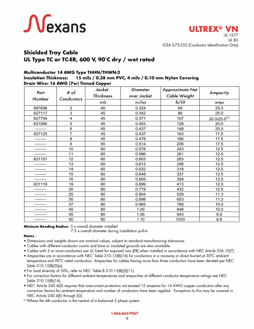
Shielded Tray CableUL Type TC or TC-ER, 600 V, 90 C dry / wet rated
Multiconductor 14 AWG Type THHN/THWN-2Insulation Thickness: 15 mils / 0.38 mm PVC, 4 mils / 0.10 mm Nylon CoveringDrain Wire: 16 AWG (7w) Tinned Copper
ULTREX® VN®
°
°°
ICEA S-73-532 (Conductor Identification Only)
Jacket
Thickness
Diameter
over Jacket
Approximate Net
Cable WeightAmpacity
mils inches lb/kft amps697698 2 45 0.324 69 25.0627117 3 45 0.342 86 25.0627794 4 45 0.371 107 20.0/25.0(1)
631085 5 45 0.403 128 20.0-------- 6 45 0.437 148 20.0627125 7 45 0.437 163 17.5-------- 8 45 0.478 186 17.5-------- 9 60 0.514 206 17.5-------- 10 60 0.578 243 12.5-------- 11 60 0.586 261 12.5631101 12 60 0.603 283 12.5-------- 13 60 0.613 298 12.5-------- 14 60 0.632 318 12.5-------- 15 60 0.648 337 12.5-------- 16 60 0.665 358 12.5631119 19 60 0.699 413 12.5-------- 20 60 0.719 432 12.5-------- 25 60 0.804 529 11.3-------- 30 80 0.898 653 11.3-------- 37 80 0.965 789 10.0-------- 40 80 1.00 848 10.0-------- 45 80 1.06 943 8.8-------- 50 80 1.10 1033 8.8
Part
Number
# of
Conductors

1-866-663-9267
10
UL 1277 UL 83
Mininum Bending Radius: 5 x overall diameter installed 7.5 x overall diameter during installation pull-in.Notes : • Dimensions and weights shown are nominal values, subject to standard manufacturing tolerances. • Cables with different conductor counts and bare or insulated grounds are also available.• Cables with 3 or more conductors are UL listed for exposed runs (ER) when installed in accordance with NEC Article 336.10(7). • Ampacities are in accordance with NEC Table 310.15(B)(16) for conductors in a raceway or direct buried at 30°C ambient
temperature and 90°C rated conductors. Ampacities for cables having more than three conductors have been derated per NEC Table 310.15(B)(3)(a).
• For load diversity of 50%, refer to NEC Table B.310.15(B)(2)(11). • For correction factors for different ambient temperatures and ampacities at different conductor temperature ratings see NEC Table 310.15(B)(16).
• NEC Article 240.4(D) requires that overcurrent protection not exceed 20 amperes for 12 AWG copper conductors after any correction factors for ambient temperature and number of conductors have been applied. Exceptions to this may be covered in NEC Article 240.4(E) through (G).
(1) Where the 4th conductor is the neutral of a balanced 3 phase system.
Unshielded Tray CableUL Type TC or TC-ER, 600 V, 90 C dry / wet rated
Multiconductor 12 AWG Type THHN/THWN-2Insulation Thickness: 15 mils / 0.38 mm PVC, 4 mils / 0.10 mm Nylon Covering
ULTREX® VN®
°
°°
ICEA S-73-532 (Conductor Identification Only)
Jacket
Thickness
Diameter over
Jacket
Approximate Net
Cable WeightAmpacity
mils inches lb/kft amps696955 2 Flat 45 .225 x .359 77 30.0696963 3 45 0.376 105 30.0696971 4 45 0.408 126 24.0/30.0(1)
697292 5 45 0.448 166 24.0------- 6 45 0.488 196 24.0
697300 7 45 0.488 215 21.0------- 8 45 0.559 253 21.0
696989 9 60 0.601 296 21.0696997 10 60 0.641 328 15.0------- 11 60 0.650 357 15.0
697003 12 60 0.670 376 15.0------- 13 60 0.682 414 15.0------- 14 60 0.704 443 15.0------- 15 60 0.723 470 15.0
697001 16 60 0.742 490 15.0697318 19 60 0.782 573 15.0697029 20 60 0.806 582 15.0697037 25 80 0.945 778 13.5688770 30 80 1.01 915 13.5627455 37 80 1.09 1107 12.0------- 40 80 1.13 1216 12.0------- 45 80 1.19 1358 10.5------- 50 80 1.24 1497 10.5
Part Number# of
Conductors

1-866-663-9267
11
UL 1277 UL 83
Mininum Bending Radius: 5 x overall diameter installed 7.5 x overall diameter during installation pull-in.Notes : • Dimensions and weights shown are nominal values, subject to standard manufacturing tolerances. • Cables with different conductor counts and bare or insulated grounds are also available.• Cables with 3 or more conductors are UL listed for exposed runs (ER) when installed in accordance with NEC Article 336.10(7). • Ampacities are in accordance with NEC Table 310.15(B)(16) for conductors in a raceway or direct buried at 30°C ambient
temperature and 90°C rated conductors. Ampacities for cables having more than three conductors have been derated per NEC NEC Table 310.15(B)(3)(a).
• For load diversity of 50%, refer to NEC Table B.310.15(B)(2)(11). • For correction factors for different ambient temperatures and ampacities at different conductor temperature ratings see NEC
Table 310.15(B)(16).• NEC Article 240.4(D) requires that overcurrent protection not exceed 20 amperes for 12 AWG copper conductors after any
correction factors for ambient temperature and number of conductors have been applied. Exceptions to this may be covered in NEC Article 240.4(E) through (G).
(1) Where the 4th conductor is the neutral of a balanced 3 phase system.
Shielded Tray CableUL Type TC or TC-ER, 600 V, 90 C dry / wet rated
Multiconductor 12 AWG Type THHN/THWN-2Insulation Thickness: 15 mils / 0.38 mm PVC, 4 mils / 0.10 mm Nylon CoveringDrain Wire: 16 AWG (7w) Tinned Copper
ULTREX® VN®
°
°°
ICEA S-73-532 (Conductor Identification Only)
Jacket
Thickness
Diameter
over Jacket
Approximate Net
Cable WeightAmpacity
mils inches lb/kft amps631044 2 45 0.368 89 30.0627539 3 45 0.388 117 30.0631051 4 45 0.423 147 24.0/30.0(1)
690032 5 45 0.460 183 24.0------- 6 45 0.500 208 24.0
631069 7 45 0.500 227 21.0------- 8 60 0.572 265 21.0
688929 9 60 0.614 316 21.0------- 10 60 0.654 345 15.0------- 11 60 0.663 369 15.0
631077 12 60 0.683 400 15.0------- 13 60 0.695 426 15.0------- 14 60 0.717 455 15.0------- 15 60 0.736 482 15.0------- 16 60 0.755 502 15.0------- 19 60 0.795 585 15.0------- 20 60 0.819 627 15.0------- 25 80 0.958 790 13.5------- 30 80 1.02 927 13.5------- 37 80 1.10 1119 12.0------- 40 80 1.14 1228 12.0------- 45 80 1.21 1370 10.5------- 50 80 1.25 1509 10.5
Part
Number
# of
Conductors

1-866-663-9267
12
UL 1277 UL 83
Mininum Bending Radius: 5 x overall diameter installed 7.5 x overall diameter during installation pull-in.Notes : • Dimensions and weights shown are nominal values, subject to standard manufacturing tolerances. • Cables with different conductor counts and bare or insulated grounds are also available.• Cables with 3 or more conductors are UL listed for exposed runs (ER) when installed in accordance with NEC Article 336.10(7). • Ampacities are in accordance with NEC Table 310.15(B)(16) for conductors in a raceway or direct buried at 30°C ambient temperature and 90°C rated conductors. conductors. Ampacities for cables having more than three conductors have been deratedper NEC Table 310.15(B)(3)(a).
• For load diversity of 50%, refer to NEC Table B.310.15(B)(2)(11). • For correction factors for different ambient temperatures and ampacities at different conductor temperature ratings see NEC
Table 310.15(B)(16).• NEC Article 240.4(D) requires that overcurrent protection not exceed 30 amperes for 10 AWG copper conductors after any
correction factors for ambient temperature and number of conductors have been applied. Exceptions to this may be covered in NEC Article 240.4(E) through (G).
(1) Where the 4th conductor is the neutral of a balanced 3 phase system.
Unshielded Tray CableUL Type TC or TC-ER, 600 V, 90 C dry / wet rated
Multiconductor 10 AWG Type THHN/THWN-2Insulation Thickness: 20 mils / 0.51 mm PVC, 4 mils / 0.10 mm Nylon Covering
ULTREX® VN®
°
°°
ICEA S-73-532 (Conductor Identification Only)
Jacket
Thickness
Diameter
over Jacket
Approximate Net
Cable WeightAmpacity
mils inches lb/kft amps696922 2 Flat 45 0.260 x 0.428 112 40696930 3 45 0.448 159 40697284 4 45 0.490 200 32/40(1)
688309 5 60 0.568 263 32------- 6 60 0.617 324 32
696948 7 60 0.617 346 28------- 8 60 0.668 397 28
627646 9 60 0.721 459 28------- 10 60 0.770 488 20------- 11 60 0.782 530 20
627257 12 60 0.807 572 20------- 13 80 0.862 646 20------- 14 80 0.890 735 20------- 15 80 0.913 780 20------- 16 80 0.938 795 20------- 19 80 0.987 914 20------- 20 80 1.02 954 20------- 25 80 1.14 1178 18------- 30 80 1.22 1394 18------- 37 80 1.32 1693 16------- 40 80 1.37 1824 16------- 45 80 1.45 2040 14------- 50 80 1.51 2253 14
Part
Number
# of
Conductors

1-866-663-9267
13
UL 1277 UL 83
Mininum Bending Radius: 5 x overall diameter installed 7.5 x overall diameter during installation pull-in.Notes : • Dimensions and weights shown are nominal values, subject to standard manufacturing tolerances. • Cables with different conductor counts and bare or insulated grounds are also available. • Cables with 3 or more conductors are UL listed for exposed runs (ER) when installed in accordance with NEC Article 336.10(7). • Ampacities are in accordance with NEC Table 310.15(B)(16) for conductors in a raceway or direct buried at 30°C ambient
temperature and 90°C rated conductors. Ampacities for cables having more than three conductors have been derated per NECTable 310.15(B)(3)(a).
• For load diversity of 50%, refer to NEC Table B.310.15(B)(2)(11). • For correction factors for different ambient temperatures and ampacities at different conductor temperature ratings see NEC
Table 310.15(B)(16).• NEC Article 240.4(D) requires that overcurrent protection not exceed 30 amperes for 10 AWG copper conductors after any
correction factors for ambient temperature and number of conductors have been applied. Exceptions to this may be covered in NEC Article 240.4(E) through (G).
(1) Where the 4th conductor is the neutral of a balanced 3 phase system.
Shielded Tray CableUL Type TC or TC-ER, 600 V, 90 C dry / wet rated
Multiconductor 10 AWG Type THHN/THWN-2Insulation Thickness: 20 mils / 0.51 mm PVC, 4 mils / 0.10 mm Nylon CoveringDrain Wire: 16 AWG (7w) Tinned Copper
ULTREX® VN®
°
°°
ICEA S-73-532 (Conductor Identification Only)
Jacket
Thickness
Diameter
over Jacket
Approximate Net
Cable WeightAmpacity
mils inches lb/kft amps631028 2 45 0.428 127 40------- 3 45 0.454 169 40
631036 4 45 0.496 207 32/40(1)
690057 5 60 0.574 278 32------- 6 60 0.623 322 32------- 7 60 0.623 363 28------- 8 60 0.683 409 28------- 9 60 0.736 456 28------- 10 60 0.785 503 20------- 11 60 0.797 545 20
689679 12 80 0.862 625 20------- 13 80 0.877 661 20------- 14 80 0.905 750 20------- 15 80 0.928 795 20------- 16 80 0.953 848 20------- 19 80 1.02 925 20------- 20 80 1.03 970 20------- 25 80 1.16 1190 18------- 30 80 1.24 1410 18------- 37 80 1.33 1710 16------- 40 80 1.38 1840 16------- 45 80 1.47 2055 14------- 50 80 1.52 2270 14
Part
Number
# of
Conductors
1-866-663-9267
14
UL 1277 UL 83
ICEA S-95-658
* DOW construction cables.
Mininum Bending Radius: 5 x overall diameter installed Bend Radius : 7.5 x overall diameter during installation pull-in.Notes : • Dimensions and weights shown are nominal values, subject to standard manufacturing tolerances. • Cables with different conductor counts and bare or insulated grounds are also available. • Cables are UL listed for exposed runs (ER) when installed in accordance with NEC Article 336.10(7). • Ampacities are in accordance with NEC Table 310.15(B)(16) for conductors in a raceway or direct buried at 30°C ambient
temperature and 90°C rated conductors. • For correction factors for different ambient temperatures and ampacities at different conductor temperature ratings see NEC Table 310.15(B)(16).
(1) NEC Article 240.4(D) requires that overcurrent protection not exceed 15 amperes for 14 AWG, 20 amperes for 12 AWG,and 30 amperes for 10 AWG copper conductors after any correction factors for ambient temperature and number of conductors have been applied. Exceptions to this may be covered in NEC Article 240.4(E) through (G).
* DOW construction means:• Control conductors are color coded – E2 (See chart page 26)• Power conductors are black with numbers – M4 (See chart page 26)• fillers where applicable
ULTREX® VN
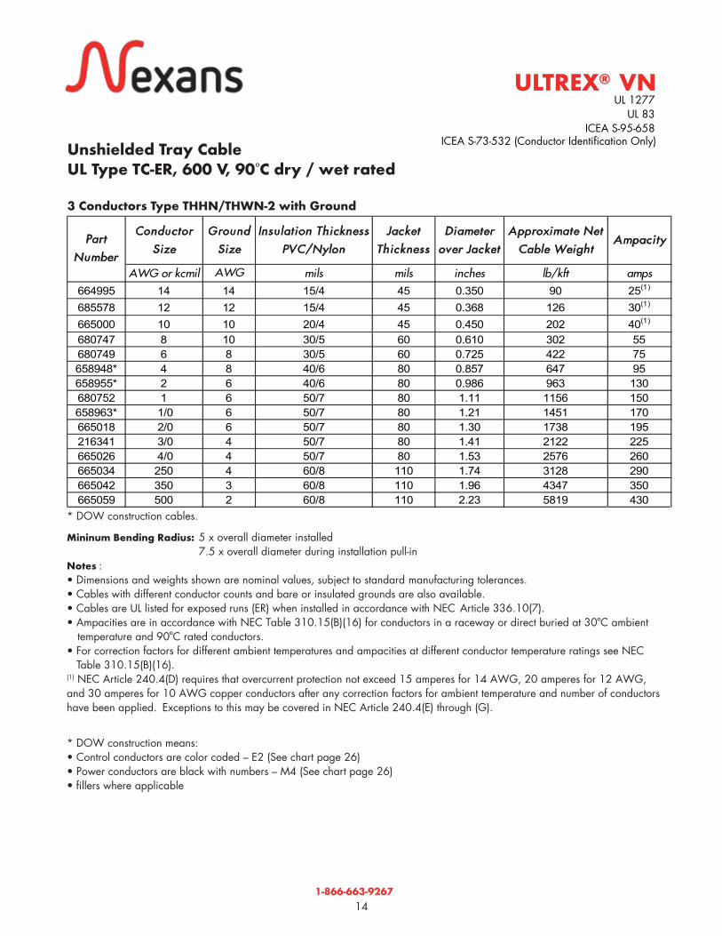
Unshielded Tray CableUL Type TC-ER, 600 V, 90 C dry / wet rated
3 Conductors Type THHN/THWN-2 with Ground
®
°°
°
ICEA S-73-532 (Conductor Identification Only)
Conductor
Size
Ground
Size
Insulat ion Thickness
PVC/Nylon
Jacket
Thickness
Diameter
over Jacket
Approximate Net
Cable WeightAmpacity
AWG or kcmil AWG mils mils inches lb/kft amps664995 14 14 15/4 45 0.350 90 25(1)
685578 12 12 15/4 45 0.368 126 30(1)
665000 10 10 20/4 45 0.450 202 40(1)
680747 8 10 30/5 60 0.610 302 55680749 6 8 30/5 60 0.725 422 75658948* 4 8 40/6 80 0.857 647 95658955* 2 6 40/6 80 0.986 963 130680752 1 6 50/7 80 1.11 1156 150658963* 1/0 6 50/7 80 1.21 1451 170665018 2/0 6 50/7 80 1.30 1738 195216341 3/0 4 50/7 80 1.41 2122 225665026 4/0 4 50/7 80 1.53 2576 260665034 250 4 60/8 110 1.74 3128 290665042 350 3 60/8 110 1.96 4347 350665059 500 2 60/8 110 2.23 5819 430
Part
Number

1-866-663-9267
15
* DOW construction cables
Mininum Bending Radius : 5 x overall diameter installed 7.5 x overall diameter during installation pull-in.
Notes:• Dimensions and weights shown are nominal values, subject to standard manufacturing tolerances. • Cables with different conductor counts and bare or insulated grounds are also available. • Cables are UL listed for exposed runs (ER) when installed in accordance with NEC Article 336.10(7). • Ampacities are in accordance with NEC Table 310.15(B)(16) for conductors in a raceway or direct buried at 30°C ambient
temperature and 90°C rated conductors. Ampacities for cables having more than three conductors have been derated per NEC Table 310.15(B)(3)(a).
• For correction factors for different ambient temperatures and ampacities at different conductor temperature ratings see NEC Table 310.15(B)(16).
(1) Where the 4th conductor is the neutral of a balanced 3 phase system.
* DOW construction means:• Control conductors are color coded – E2 (See chart page 26)• Power conductors are black with numbers – M4 (See chart page 26)• where applicable
Unshielded Tray CableUL Type TC-ER, 600 V, 90 C dry / wet rated
4 Conductors Type THHN/THWN-2 with Ground
ULTREX® VNUL 1277
UL 83 ICEA S-95-658
®
°
°°
ICEA S-73-532 (Conductor Identification Only)
Conductor
Size
Ground
Size
Insu lation Thickness
PVC/Nylon
Jacket
Thickness
Diameter
over Jacket
Approximate Net
Cable Weight
AWG or kcmil AWG mils mils inches lb/kft amps amps(1)
680748 8 10 30/5 60 0.661 353 44 55680750 6 8 30/5 60 0.796 516 60 75697581 4 8 40/6 80 0.957 804 76 95680754 2 6 40/6 80 1.10 1108 104 130------- 1 6 50/7 80 1.25 1519 120 150
680753 1/0 6 50/7 80 1.31 1811 136 170669143* 2/0 6 50/7 80 1.45 2288 156 195
------- 3/0 4 50/7 80 1.58 2756 180 225669275 4/0 4 50/7 110 1.77 3437 208 260------- 250 4 60/8 110 1.94 4046 232 290
669283* 350 3 60/8 110 2.18 5480 280 350669291* 500 2 60/8 110 2.49 7574 344 430
AmpacityPar t
Number
1-866-663-9267
16
ULTREX® VN
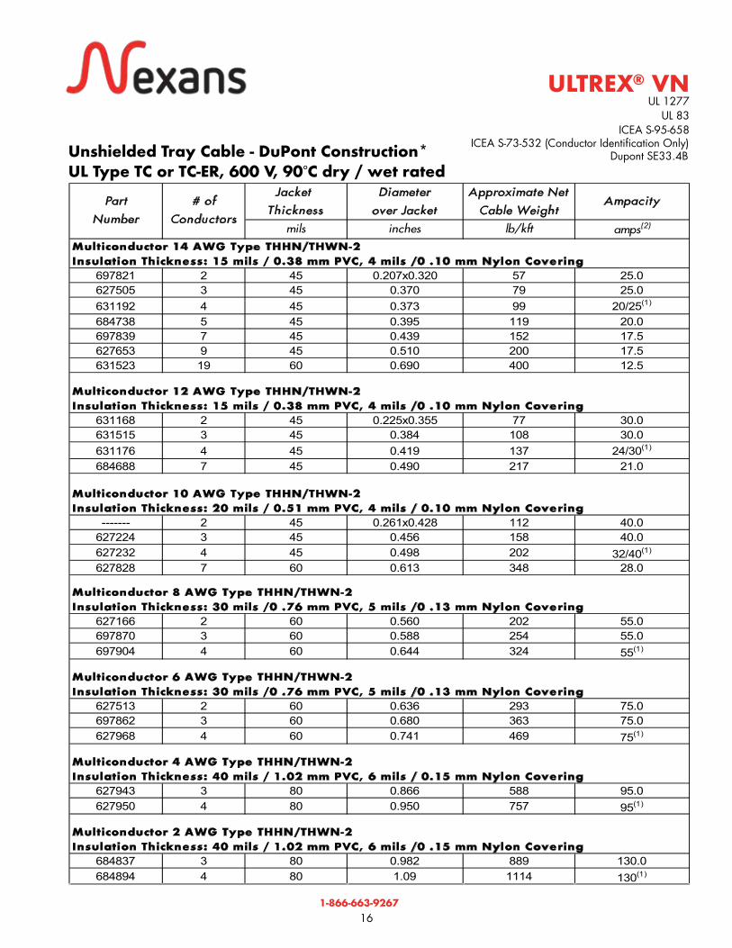
Unshielded Tray Cable - DuPont Construction*UL Type TC or TC-ER, 600 V, 90 C dry / wet rated
UL 1277 UL 83
ICEA S-95-658 ICEA S-73-532 (Conductor Identification Only) Dupont SE33.4B
®
°Jacket
Thickness
Diameter
over Jacket
Approximate Net
Cable WeightAmpacity
mils inches lb/kft amps(2)
Multiconductor 14 AWG Type THHN/THWN-2
Insulation Thickness: 15 mils / 0.38 mm PVC, 4 mils /0 .10 mm Nylon Covering
697821 2 45 0.207x0.320 57 25.0627505 3 45 0.370 79 25.0631192 4 45 0.373 99 20/25(1)
684738 5 45 0.395 119 20.0697839 7 45 0.439 152 17.5627653 9 45 0.510 200 17.5631523 19 60 0.690 400 12.5
Multiconductor 12 AWG Type THHN/THWN-2
Insulation Thickness: 15 mils / 0.38 mm PVC, 4 mils /0 .10 mm Nylon Covering
631168 2 45 0.225x0.355 77 30.0631515 3 45 0.384 108 30.0631176 4 45 0.419 137 24/30(1)
684688 7 45 0.490 217 21.0
Multiconductor 10 AWG Type THHN/THWN-2
Insulation Thickness: 20 mils / 0.51 mm PVC, 4 mils / 0.10 mm Nylon Covering
------- 2 45 0.261x0.428 112 40.0627224 3 45 0.456 158 40.0627232 4 45 0.498 202 32/40(1)
627828 7 60 0.613 348 28.0
Multiconductor 8 AWG Type THHN/THWN-2
Insulation Thickness: 30 mils /0 .76 mm PVC, 5 mils /0 .13 mm Nylon Covering
627166 2 60 0.560 202 55.0697870 3 60 0.588 254 55.0697904 4 60 0.644 324 55(1)
Multiconductor 6 AWG Type THHN/THWN-2
Insulation Thickness: 30 mils /0 .76 mm PVC, 5 mils /0 .13 mm Nylon Covering
627513 2 60 0.636 293 75.0697862 3 60 0.680 363 75.0627968 4 60 0.741 469 75(1)
Multiconductor 4 AWG Type THHN/THWN-2
Insulation Thickness: 40 mils / 1.02 mm PVC, 6 mils / 0.15 mm Nylon Covering
627943 3 80 0.866 588 95.0627950 4 80 0.950 757 95(1)
Multiconductor 2 AWG Type THHN/THWN-2
Insulation Thickness: 40 mils / 1.02 mm PVC, 6 mils /0 .15 mm Nylon Covering
684837 3 80 0.982 889 130.0684894 4 80 1.09 1114 130(1)
Part
Number
# of
Conductors

1-866-663-9267
17
ULTREX® VN
Composite Conductors Type THHN/THWN-2 with Insulated Ground
Composite - 4 Control Conductors with 3 Power Conductors and 1 Insulated Ground
Mininum Bending Radius : 5 x overall diameter installed 7.5 x overall diameter during installation pull-in.
Notes for DuPont Constructions:• Dimensions and weights shown are nominal values, subject to standard manufacturing tolerances. • Cables with 3 or more conductors are UL listed for exposed runs (ER) when installed in accordance with NEC Article 336.10(7). (1) Where the 4th conductor is the neutral of a balanced 3 phase system.(2) Conductor ampacities are in accordance with NEC Table 310.15(B)(16) for conductors in a raceway or direct buried at 30°C
ambient temperature and 90°C rated conductors. Ampacities for cables having more than three conductors have been derated.per NEC Table 310.15(B)(3)(a).
• For correction factors for different ambient temperatures and ampacitities at different conductor temperature ratings see NEC Table 310.15(B)(16).
• NEC Article 240.4(D) requires that overcurrent protection not exceed 15 amperes for 14 AWG, 20 amperes for 12 AWG, and 30 amperes for 10 AWG copper conductors after any correction factors for ambient temperature and number of conductors have been applied. Exceptions to this may be covered in NEC Article 240.4(E) through (G).
*Dupont construction means:• Conductor black insulation with white print – numbered conductors (Method 4). See chart on page 26.• Nylon – where applicable• Mylar tape around core
Unshielded Tray Cable - DuPont Construction* - (continued)UL Type TC or TC-ER, 600 V, 90 C dry / wet rated
UL 1277 UL 83
ICEA S-95-658
Dupont SE33.4B
®
°
°°
ICEA S-73-532 (Conductor Identification Only)
Control
Size
Insulat ion
Thickness
PVC/Nylon
Power
Size
Insulat ion
Thickness
PVC/Nylon
Ground
Size
Jacket
Thickness
Diameter
Over
Jacket
Approximate
Net Cable
Weight
Control
Ampacity
Power
Ampacity
AWG mils AWG mils AWG mils inches lb/kft amps amps 697813 14 45 12 45 12 60 0.515 220 17.5 21.0697805 14 45 10 45 10 60 0.575 288 17.5 28.0
Part
Number

1-866-663-9267
18
Composite Conductors Type THHN/THWN-2 with Ground Composite - 4 Control Conductors with 3 Power Conductors and 1 Ground
Mininum Bending Radius: 5 x overall diameter installed 7.5 x overall diameter during installation pull-in.
Notes :• Dimensions and weights shown are nominal values, subject to standard manufacturing tolerances. • Cables are UL listed for exposed runs (ER) when installed in accordance with NEC Article 336.10(7).• Ampacities are in accordance with NEC Table 310.15(B)(16) for conductors in a raceway or direct buried at 30°C ambient
temperature and 90°C rated conductors. Ampacities for cables having more than three conductors have been derated per NEC Table 310.15(B)(16).
• For correction factors for different ambient temperatures and ampacitities at different conductor temperature ratings see NEC Table 310.15(B)(16).
• NEC Article 240.4(D) requires that overcurrent protection not exceed 15 amperes for 14 AWG, 20 amperes for 12 AWG, and 30 amperes for 10 AWG copper conductors after any correction factors for ambient temperature and number of conductorshave been applied. Exceptions to this may be covered in NEC Article 240.4(E) through (G).
*DOW construction means:• Control conductors are color coded – E2 (See chart page 26)• Power conductors are black with numbers – M4 (See chart page 26)• Fillers where applicable
ULTREX® VN
Unshielded Tray Cable - Dow Construction*UL Type TC -ER, 600 V, 90°C dry / wet rated
UL 1277 UL 83
ICEA S-95-658
®
°°
ICEA S-73-532 (Conductor Identification Only)
Control
Size
Insulat ion
Thickness
PVC/Nylon
Power
Size
Insulat ion
Thickness
PVC/Nylon
Ground
Size
Jacket
Thickness
Diameter
Over
Jacket
Approximate
Net Cable
Weight
Control
Ampacity
Power
Ampacity
AWG mils AWG mils AWG mils inches lb/kft amps amps 680759 14 15/4 12 15/4 12 60 0.515 205 17.5 21.0658872 14 15/4 10 15/4 10 60 0.575 286 17.5 28.0658880 14 15/4 8 30/4 10 60 0.675 380 17.5 55.0658898 14 15/4 6 30/4 8 60 0.750 502 17.5 75.0658906 14 15/4 4 40/6 8 80 0.905 727 17.5 95.0658914 14 15/4 2 40/6 6 80 1.01 1029 17.5 130.0
Part
Number

1-866-663-9267
19
Notes : • Dimensions and weights shown are nominal values, subject to standard manufacturing tolerances. • Cables are UL listed for exposed runs (ER) when installed in accordance with NEC Article 336.10(7). • Cables with different conductor counts and bare or insulated grounds are also available. • Ampacities are in accordance with NEC Table 310.15(B)(16) for conductors in a raceway or direct buried at 30°C ambient
temperature and 90°C rated conductors. Ampacities for cables having more than three conductors have been derated per NEC Table 310.15(B)(3)(a).
• For correction factors for different ambient temperatures and ampacities at different conductor temperature ratings see NEC Table 310.15(B)(16).
• NEC Article 240.4(D) requires that overcurrent protection not exceed 20 amperes for 12 AWG, and 30 amperes for 10 AWG copper conductors after any correction factors for ambient temperature and number of conductors have been applied. Exceptions to this may be covered in NEC Article 240.4(E) through (G).
Color codes:• Power and Control conductors are black with number coding per Method 4 of ICEA S-73-532.
Unshielded Tray CableUL Type TC -ER, 600 V, 90°C dry / wet rated
Composite Conductors Type THHN/THWN-2 with GroundComposite - 4 Control Conductors with 3 Power Conductors and 1 Ground
ULTREX® VNUL 1277
UL 83 ICEA S-95-658
®
°°
Mininum Bending Radius: 5 x overall diameter installed7.5 x overall diameter during installation pull-in
ICEA S-73-532 (Conductor Identification Only)
Control
Size
Insulat ion
Thickness
PVC/Nylon
Power
Size
Insulat ion
Thickness
PVC/Nylon
Ground
Size
Jacket
Thickness
Diameter
Over
Jacket
Approximate
Net Cable
Weight
Control
Ampacity
Power
Ampacity
AWG mils AWG mils AWG mils inches lb/kft amps amps 684126 12 15/4 10 20/4 10 60 0.585 320 21 28627042 12 15/4 8 30/5 10 60 0.675 405 21 55627810 12 15/4 6 30/5 8 60 0.720 530 21 75697680 12 15/4 4 40/6 6 80 0.890 760 21 95682773 12 15/4 2 40/6 6 80 1.02 1061 21 130
Part
Number

1-866-663-9267
20
Applications
Nexans 600 V ULTREX® XL Tray Cables are listed as type TC or TC-ER under UL 1277 Electrical Power and Control Cables. These cables may be installed in wet or dry locations; in cable trays, raceways and open air; and are suitable for exposure to weather, direct burial and for Class I, Div. 2 (also Zone 2) and Class II, Div. 2 hazardous locations per NEC. Cables with 3 or more conductors are UL listed for exposed runs (ER) when installed in accordance with NEC Article 336.10(7).
Construction
Conductor: bare, annealed copper conforming to ASTM B3 and Class B stranded in accordance with ASTM B8, from 14 AWG to 500 kcmil.
Insulation: flame-retardant cross-linked polyethylene meeting the requirements for XHHW-2 per UL 44 and the requirements of ICEA S-95-658 for XLPE insulation as standard. Sizes 14 AWG to 8 AWG are VW-1, and sizes 6 AWG and larger are not VW-1.
Assembly: conductors are cabled in concentric layers with interstices filled with suitable fillers, as required. Ground wires are sized as required by UL 1277 (refer to the applicable product tables for the standard sizes provided). Sizes 14 AWG to 6 AWG have an insulated green ground wire. Sizes 4 AWG and larger have a bare ground wire. A binder tape of synthetic material assembles the core in a tight circular configuration.
Jacket: UL listed sunlight and moisture resistant, sequentially length marked, black, flame retardant polyvinyl chloride (PVC) material meeting the requirements of UL 1277.
Sample Print Legend: (mon/year) NEXANS ULTREX-XL 3/C 250 kcmil - 4 AWG GRD CU TYPE TC-ER XHHW-2 (UL) E64956 F SUN RES DIR BUR 600V
Conductor Identification(See page 26 of this catalog)
14 AWG to 10 AWG:2–37 conductors: Color coded per Method #1-E2 per ICEA S-73-532 38 and More Conductors: Black with number coding per Method 4 of ICEA S-73-532
8 AWG to 500 kcmil: black with number coding per Method 4 of ICEA S-73-532
Specifications
• Meets UL 1277: Power and Control Tray
Cables with Optional Fiber Members. • Meets UL 44: Thermoset-Insulated Wires
and Cables.• Meets ICEA S-95-658, NEMA Publication
No. WC-70: Nonshielded Power Cables Rated 2000 Volts or Less for the Distribution of Electrical Energy.
Product features
• UL approved cables Type TC or TC-ER,
600 V.• UL approved insulated conductors.• Cables pass UL 1685 and IEEE 383
vertical tray fire tests at 70,000 BTU/hr.• All cables pass IEEE 1202
and FT4 70,000 BTU/hr flame test.
• All cables pass ICEA T-29-520 210,000
BTU/hr flame test.• For use in power, lighting, control and
signal circuits.• Can be used within industrial
establishments where serviced by qualified personnel and not subject to physical damage.
• Continuous operation temperatures of
90°C dry and wet.
• Can be used In Class I Division 2 andClass II Division 2 Hazardous Locations and Intrinsically Safe applications as permitted by NEC Articles 392, 501, 502, 503, and 505.*
XLPE/PVC Type TC or TC-ER 600 VoltPower and Control CableTemperature rating of 90°C dry / wet rated
• As indicated in UL 1277: The overall jackets of these cables are a “gas/vapor tight continuous sheath” as discussed in NEC Article 501.15(D) & (E).*
• For use in cable trays, raceways, conduits, or for aerial applications where installed with a messenger.
• For Direct Burial applications.• Cables of 2 or more conductors (plus
a ground conductor) are UL listed for Exposed Run (ER) per NEC Article 336.10(7): 1) Cables sized from 14 AWG to 6 AWG
have an insulated ground conductor.2) Cables sized 4 AWG and larger have
a bare ground conductor.• As permitted in NEC Articles 336.10 and
725 for Class 1 circuits. • As permitted for non-power-limited
alarm circuits as defined in NEC Articles 336.10 and 760.27.
• Lead free and RoHS compliant• Sunlight and moisture resistant
Options
The following constructions can be provided on special orders: • Cables sized 4 AWG and larger with an
insulated ground conductor• Aluminum alloy conductors in sizes 12
AWG to 1000 kcmil • Insulated or bare ground wires • Different conductor methods • Shields of aluminum/mylar tape (with or
without a tinned copper drain wire)• Composite constructions of different sized
conductors.• 2000 volt rated cables with RHH/RHW-2
insulated conductors.
* Use in hazardous locations: Please note that no investigation of these cables has been performed regarding the transmission of gases or vapors through the core. When these cables are used in hazardous locations they should be sealed properly as required by the NEC.
ULTREX® XL ®
°°
• Cold bend of –25°C per UL 1277

1-866-663-9267
21
UL 1277UL 44
ICEA S-73-532 (Conductor Identification Only)
Notes: • Dimensions and weights shown are nominal values, subject to standard manufacturing tolerances. • Cables with different conductor counts and bare or insulated grounds are also available. • Cables with 3 or more conductors are UL listed for exposed runs (ER) when installed in accordance with NEC Article 336. 10(7). • Ampacities are in accordance with NEC Table 310.15(B)(16) for conductors in raceway or direct buried at 30°C ambient
temperature and 90°C rated conductors. Ampacities for cables having more than three conductors have been derated per NEC Table 310.15(B)(3)(a).
•For load diversity of 50%, refer to NEC Table B.310.15(B)(2)(11). • For correction factors for different ambient temperatures and ampacities at different conductor temperature raitings see NEC
Table 310.15(B)(16).• NEC Article 240.4(D) requires that overcurrent protection not exceed 15 amperes for 14 AWG copper conductors after any
correction factors for ambient temperature and number of conductors have been applied. Exceptions to this may be covered in NEC 2008 Article 240.4(E) through (G).
(1) Where the 4th conductor is the neutral of a balanced 3 phase system.
Unshielded Tray CableUL Type TC or TC-ER, 600 V, 90°C dry / wet rated
Multiconductor 14 AWG Type XHHW-2Insulation Thickness: 30 mils / 0.76 mm
®ULTREX XL ®
°°
Mininum Bending Radius: 5 x overall diameter installed7.5 x overall diameter during installation pull-in
Jacket
Thickness
Diameter
over Jacket
Approximate Net
Cable WeightAmpacity
mils inches lb/kft amps603092 2 45 0.385 73 25.0603043 3 45 0.405 95 25.0603118 4 45 0.445 119 20.0/25.0(1)
602995 5 45 0.485 144 20.0------ 6 45 0.525 169 20.0
602862 7 45 0.525 187 17.5------ 8 60 0.600 214 17.5
602920 9 60 0.645 238 17.5------ 10 60 0.685 262 12.5------ 11 60 0.695 282 12.5
602888 12 60 0.715 303 12.5------ 13 60 0.730 323 12.5------ 14 60 0.755 345 12.5
620385 15 60 0.770 366 12.5603126 19 60 0.855 451 12.5
------ 20 60 0.865 471 12.5603134 25 80 1.01 615 11.3
------ 30 80 1.08 720 11.3------ 35 80 1.14 823 10.0
602953 37 80 1.18 866 10.0------ 40 80 1.20 927 10.0------ 45 80 1.27 1031 8.8------ 50 80 1.32 1132 8.8
Part
Number
# of
Conductors

1-866-663-9267
22
Minimum Bending Radius: 5 x overall diameter installed 7.5 x overall diameter during installation pull-in.Notes : • Dimensions and weights shown are nominal values, subject to standard manufacturing tolerances. • Cables with different conductor counts and bare or insulated grounds are also available. • Cables with 3 or more conductors are UL listed for exposed runs (ER) when installed in accordance with NEC Article 336.10(7). • Ampacities are in accordance with NEC Table 310.15(B)(16) for conductors in raceway or direct buried at 30°C ambient
temperature and 90°C rated conductors. Ampacities for cables having more than three conductors have been derated per NEC Table 310.15(B)(3)(a).
• For load diversity of 50%, refer to NEC Table B.310.15(B)(2)(11).• For correction factors for different ambient temperatures and ampacities at different conductor temperature raitings see NEC
Table 310.15(B)(16).• NEC Article 240.4(D) requires that overcurrent protection not exceed 20 amperes for 12 AWG copper conductors after any
correction factors for ambient temperature and number of conductors have been applied. Exceptions to this may be covered inNEC Article 240.4(E) through (G).
1) Where the 4th conductor is the neutral of a balanced 3 phase system.
Unshielded Tray CableUL Type TC or TC-ER, 600 V, 90°C dry / wet rated
Multiconductor 12 AWG Type XHHW-2Insulation Thickness: 30 mils / 0.76 mm
®
UL 1277 UL 44
ULTREX XL®
°°
ICEA S-73-532 (Conductor Identification Only)
Jacket
Thickness
Diameter
over Jacket
Approximate Net
Cable WeightAmpacity
mils inches lb/kft amps620377 2 45 0.420 94 30.0602847 3 45 0.445 126 30.0603050 4 45 0.485 160 24.0/30.0(1)
603001 5 45 0.535 194 24.0------ 6 60 0.610 246 24.0
602870 7 60 0.610 273 21.0------ 8 60 0.660 290 21.0
603027 9 60 0.710 341 21.0------ 10 60 0.755 356 15.0------ 11 60 0.770 385 15.0
602896 12 60 0.795 416 15.0------ 13 60 0.810 445 15.0------ 14 60 0.835 476 15.0
620393 15 60 0.860 506 15.0602938 19 80 0.955 655 15.0
------ 20 80 1.00 691 15.0603142 25 80 1.12 847 13.5
------ 30 80 1.19 995 13.5------ 35 80 1.27 1142 12.0------ 37 80 1.27 1275 12.0------ 40 80 1.34 1289 12.0------ 45 80 1.41 1438 10.5------ 50 80 1.47 1582 10.5
Part
Number
# of
Conductors

1-866-663-9267
23
Minimum Bending Radius: 5 x overall diameter installed 7.5 x overall diameter during installation pull-in.Notes : • Dimensions and weights shown are nominal values, subject to standard manufacturing tolerances. • Cables with different conductor counts and bare or insulated grounds are also available. • Cables with 3 or more conductors are UL listed for exposed runs (ER) when installed in accordance with NEC Article 336.10(7). • Ampacities are in accordance with NEC Table 310.15(B)(16) for conductors in raceway or direct buried at 30°C ambient
temperature and 90°C rated conductors. Ampacities for cables having more than three conductors have been derated per NEC Table 310.15(B)(3)(a) .
• For load diversity of 50%, refer to NEC Table B.310.15(B)(2)(11).• For correction factors for different ambient temperatures and ampacities at different conductor temperature raitings see NEC Table 310.15(B)(16).
• NEC Article 240.4(D) requires that overcurrent protection not exceed 30 amperes for 10 AWG copper after any correction factors for ambient temperature and number of conductors have been applied. Exceptions to this may be covered in NEC Article 240.4(E) through (G).
(1) Where the 4th conductor is the neutral of a balanced 3 phase system.
Unshielded Tray CableUL Type TC or TC-ER, 600 V, 90°C dry / wet rated
Multiconductor 10 AWG Type XHHW-2Insulation Thickness: 30 mils / 0.76 mm
®
UL 1277 UL 44
ULTREX XL ®
°°
ICEA S-73-532 (Conductor Identification Only)
Jacket
Thickness
Diameter
over Jacket
Approximate Net
Cable WeightAmpacity
mils inches lb/kft amps603159 2 45 0.470 128 40603167 3 45 0.495 174 40603076 4 45 0.545 223 32/40(1)
603175 5 60 0.630 290 32------ 6 60 0.685 341 32
603183 7 60 0.685 382 28------ 8 60 0.740 408 28
603191 9 60 0.800 479 28------ 10 60 0.855 505 20------ 11 80 0.910 581 20------ 12 80 0.935 626 20------ 13 80 0.950 670 20------ 14 80 0.980 715 20------ 15 80 1.01 760 20------ 20 80 1.13 983 20------ 25 80 1.26 1209 18------ 30 80 1.35 1427 18------ 35 80 1.43 1644 16------ 40 80 1.51 1861 16------ 45 80 1.61 2082 14------ 50 80 1.67 2296 14
Part
Number
# of
Conductors

1-866-663-9267
24
Notes : • Dimensions and weights shown are nominal values. They are subject to standard manufacturing tolerances. • Cables with different conductor counts and bare or insulated grounds are also available. • Cables are UL listed for exposed runs (ER) when installed in accordance with NEC Article 336.10(7). • Ampacities are in accordance with NEC Table 310.15(B)(16) for conductors in a raceway or direct buried at 30°C ambient
temperature and 90°C rated conductors.• For correction factors for different ambient temperatures and ampacities at different conductor temperature ratings see NEC Table 310.15(B)(16).
(1) NEC Article 240.4(D) requires that overcurrent protection not exceed 20 amperes for 12 AWG, and 30 amperes for 10 AWG copper conductors after any correction factors for ambient temperature and number of conductors have been applied.
Exceptions to this may be covered in NEC Article 240240.4(E) through (G).
Unshielded Tray CableUL Type TC-ER, 600 V, 90°C dry / wet rated
3 Conductors Type XHHW-2 with Ground
®
UL 1277 UL 44
ICEA S-95-658
ULTREX XL ®
°°
Minimum Bending Radius: 5 x overall diameter installed 7.5 x overall diameter during installation pull-in
ICEA S-73-532 (Conductor Identification Only)
Conductor
Size
Ground
Size
Insulat ion Thickness
PVC/Nylon
Jacket
Thickness
Diameter
over Jacket
Approximate Net
Cable WeightAmpacity
AWG or kcmil AWG mils mils inches lb/kft amps
611517 12 12 30 45 1.14 145 30(1)
295196 10 10 30 45 1.14 205 45(1)
306829 8 10 45 60 1.52 323 55306845 6 8 45 60 1.52 451 75306860 4 8 45 60 1.52 595 95
------ 3 6 45 80 2.03 824 110306886 2 6 45 80 2.03 922 130
------ 1 6 55 80 2.03 1200 150306894 1/0 6 55 80 2.03 1358 170306910 2/0 6 55 80 2.03 1663 195
------ 3/0 4 55 80 2.03 2156 225306928 4/0 4 55 80 2.03 2506 260619114 250 4 65 80 2.03 2941 290
------ 300 3 65 110 2.79 3394 320619338 350 3 65 110 2.79 4103 350
------ 400 3 65 110 2.79 4818 380619148 500 2 65 110 2.79 5670 430
Part
Number
1-866-663-9267
25
.
Notes : • Dimensions and weights shown are nominal values, subject to standard manufacturing tolerances. • Cables with different conductor counts and bare or insulated grounds are also available. • Cables are UL listed for exposed runs (ER) when installed in accordance with NEC Article 336.10(7). • Ampacities are in accordance with NEC Table 310.15(B)(16) for conductors in raceway or direct buried at 30°C ambient
temperature and 90°C rated conductors, where the fourth conductor is the neutral of a balanced 3 phase, 4 wire system. • For correction factors for different ambient temperature ratings and ampacities at different conductor temperatures see NEC Table 310.15(B)(16).
(1) NEC Article 240.4(D) requires that overcurrent protection not exceed 30 amperes for 10 AWG copper conductors after anycorrection factors for ambient temperature and number of conductors have been applied. Exceptions to this may be covered in NEC Article 240.4(E) through (G).
Unshielded Tray CableUL Type TC-ER, 600 V, 90°C dry / wet rated
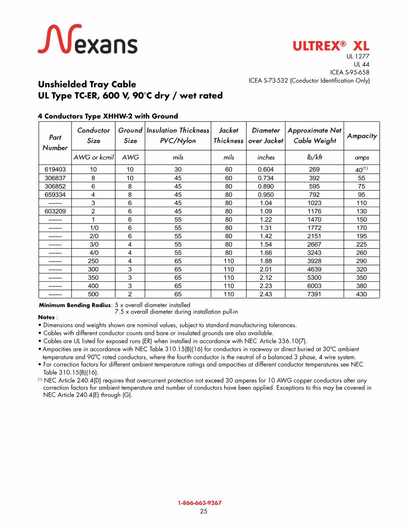
4 Conductors Type XHHW-2 with Ground
®
UL 1277 UL 44
ICEA S-95-658
ULTREX XL®
°°
Minimum Bending Radius: 5 x overall diameter installed 7.5 x overall diameter during installation pull-in
ICEA S-73-532 (Conductor Identification Only)
Conductor
Size
Ground
Size
Insulat ion Thickness
PVC/Nylon
Jacket
Thickness
Diameter
over Jacket
Approximate Net
Cable WeightAmpacity
AWG or kcmil AWG mils mils inches lb/kft amps
619403 10 10 30 60 0.604 269 40(1)
306837 8 10 45 60 0.734 392 55306852 6 8 45 80 0.890 595 75659334 4 8 45 80 0.950 792 95
------ 3 6 45 80 1.04 1023 110603209 2 6 45 80 1.09 1176 130
------ 1 6 55 80 1.22 1470 150------ 1/0 6 55 80 1.31 1772 170------ 2/0 6 55 80 1.42 2151 195------ 3/0 4 55 80 1.54 2667 225------ 4/0 4 55 80 1.66 3243 260------ 250 4 65 110 1.88 3928 290------ 300 3 65 110 2.01 4639 320------ 350 3 65 110 2.12 5300 350------ 400 3 65 110 2.23 6003 380------ 500 2 65 110 2.43 7391 430
Part
Number

1-866-663-9267
26
Conductor Printing Details Conductor Printing Details
1st “1-ONE-1” 4th “4-FOUR-4” 2nd “2-TWO-2” 5th “5-FIVE-5” 3rd “3-THREE-3” 6th “6-SIX-6”
Per ICEA S-73-532-E3.1 Method 1 and Table E2 (formerly K2)Colored Insulation with/without Colored Stripe
Conductor Insulation Stripe Conductor Insulation Stripe
1st BLACK — 19th ORANGE Blue 2nd RED — 20th YELLOW Blue 3rd BLUE — 21st BROWN Blue 4th ORANGE — 22nd BLACK Orange 5th YELLOW — 23rd RED Orange 6th BROWN — 24th BLUE Orange 7th RED Black 25th YELLOW Orange 8th BLUE Black 26th BROWN Orange 9th ORANGE Black 27th BLACK Yellow 10th YELLOW Black 28th RED Yellow 11th BROWN Black 29th BLUE Yellow 12th BLACK Red 30th ORANGE Yellow 13th BLUE Red 31st BROWN Yellow 14th ORANGE Red 32nd BLACK Brown 15th YELLOW Red 33rd RED Brown 16th BROWN Red 34th BLUE Brown 17th BLACK Blue 35th ORANGE Brown 18th RED Blue 36th YELLOW Brown
Note : The color code repeats at #1 “BLACK” as the 37th conductor (for cables with more than 36 conductors) for ULTREX-VN.
Per ICEA S-73-532-E3.4 Method 4Number Code
Conductor or Phase Identification

1-866-663-9267
27
WARNING
FLAMMABLENon-metallic covering of electrical cables will burn and under certain conditions may transmit fire when ignited.
TOXICBurning non-metallic coverings may emit acid gases, which are highly toxic, and may generate dense smoke.
CORROSIVEEmission of acid gases may corrode metal in the vicinity, such as sensitive instruments and reinforcing rod in concrete.
NOTICE
Nexans has endeavored to ensure the accuracy of the data in this publication, however we cannot be liable for the consequences of errors or omissions. All data is subject to change without notice. The installer and/or user assumes all liability for the consequences of the installation and/or use of any of our products in contravention of any applicable law, regulation or code.
1-866-663-9267
28
wire and cable
A t t h e c o r e o f p e r f o r m a n c e

09/2
016