PVB Piston Pumps - – Oleohidraulica ... · PVB Piston Pumps † Same Day Shipments of Units or...
33
PVB Piston Pumps • Same Day Shipments of Units or Part Orders • Interchangeable Parts • Fully Tested
-
Upload
hoangkhuong -
Category
Documents
-
view
220 -
download
1
Transcript of PVB Piston Pumps - – Oleohidraulica ... · PVB Piston Pumps † Same Day Shipments of Units or...

PVB Piston Pumps
• Same Day Shipments of Units or Part Orders
• Interchangeable Parts
• Fully Tested

Contents
Basic characteristics 3. . . . . . . . . . . . . . . . . . . . . . . . . . . . . . . . . . . . . . . . . . . . . . . . . . . . . . . . . . . . . . . . . . . . . . . . . . . . . . . . . . . . . . . . .
General Description 3. . . . . . . . . . . . . . . . . . . . . . . . . . . . . . . . . . . . . . . . . . . . . . . . . . . . . . . . . . . . . . . . . . . . . . . . . . . . . . . . . . . . . . . . . .
Functional symbols 3. . . . . . . . . . . . . . . . . . . . . . . . . . . . . . . . . . . . . . . . . . . . . . . . . . . . . . . . . . . . . . . . . . . . . . . . . . . . . . . . . . . . . . . . . .
Model Codes 4. . . . . . . . . . . . . . . . . . . . . . . . . . . . . . . . . . . . . . . . . . . . . . . . . . . . . . . . . . . . . . . . . . . . . . . . . . . . . . . . . . . . . . . . . . . . . . .
Operating data 5. . . . . . . . . . . . . . . . . . . . . . . . . . . . . . . . . . . . . . . . . . . . . . . . . . . . . . . . . . . . . . . . . . . . . . . . . . . . . . . . . . . . . . . . . . . . . .
Minimum Inlet Pressure Curves 5–6. . . . . . . . . . . . . . . . . . . . . . . . . . . . . . . . . . . . . . . . . . . . . . . . . . . . . . . . . . . . . . . . . . . . . . . . . . . . .
Performance data @ 1500 r/min drive speed:
PFB5, PFB10, PFB20 7 . . . . . . . . . . . . . . . . . . . . . . . . . . . . . . . . . . . . . . . . . . . . . . . . . . . . . . . . . . . . . . . . . . . . . . . . . . . . . . . . . . .
PVB5, PVB6, PVB10 8 . . . . . . . . . . . . . . . . . . . . . . . . . . . . . . . . . . . . . . . . . . . . . . . . . . . . . . . . . . . . . . . . . . . . . . . . . . . . . . . . . . . .
PVB15, PVB20, PVB29 9 . . . . . . . . . . . . . . . . . . . . . . . . . . . . . . . . . . . . . . . . . . . . . . . . . . . . . . . . . . . . . . . . . . . . . . . . . . .
PVB45,PVB90 10 . . . . . . . . . . . . . . . . . . . . . . . . . . . . . . . . . . . . . . . . . . . . . . . . . . . . . . . . . . . . . . . . . . . . . . . . . . . . . . . . . . .
Performance data @ 1800 r/min drive speed:
PFB5, PFB10, PFB20 11 . . . . . . . . . . . . . . . . . . . . . . . . . . . . . . . . . . . . . . . . . . . . . . . . . . . . . . . . . . . . . . . . . . . . . . . . . . .
PVB5, PVB6, PVB10 12 . . . . . . . . . . . . . . . . . . . . . . . . . . . . . . . . . . . . . . . . . . . . . . . . . . . . . . . . . . . . . . . . . . . . . . . . . . . . . .
PVB15, PVB20, PVB29 13 . . . . . . . . . . . . . . . . . . . . . . . . . . . . . . . . . . . . . . . . . . . . . . . . . . . . . . . . . . . . . . . . . . . . . . . . . .
PVB45, PVB90 14 . . . . . . . . . . . . . . . . . . . . . . . . . . . . . . . . . . . . . . . . . . . . . . . . . . . . . . . . . . . . . . . . . . . . . . . . . . . . . . . . . . . .
Control data for PVB pumps 15 . . . . . . . . . . . . . . . . . . . . . . . . . . . . . . . . . . . . . . . . . . . . . . . . . . . . . . . . . . . . . . . . . . . . . . . . . . . . . . .
Noise levels 16. . . . . . . . . . . . . . . . . . . . . . . . . . . . . . . . . . . . . . . . . . . . . . . . . . . . . . . . . . . . . . . . . . . . . . . . . . . . . . . . . . . . . . . . . . . . . . .
Installation data
PFB5 SAE flange mounting 17 . . . . . . . . . . . . . . . . . . . . . . . . . . . . . . . . . . . . . . . . . . . . . . . . . . . . . . . . . . . . . . . . . . . . . . . . . . . .
PFB10 SAE flange mounting 18 . . . . . . . . . . . . . . . . . . . . . . . . . . . . . . . . . . . . . . . . . . . . . . . . . . . . . . . . . . . . . . . . . . . . . . . . . . .
PFB20 SAE flange mounting 19 . . . . . . . . . . . . . . . . . . . . . . . . . . . . . . . . . . . . . . . . . . . . . . . . . . . . . . . . . . . . . . . . . . . . . . . . . . .
PVB5/6 SAE flange mounting C & CM pressure compensator controls 20 . . . . . . . . . . . . . . . . . . . . . . . . . . . . . . . . . . . . . . .
PVB5/6 side ported thru shaft 21 . . . . . . . . . . . . . . . . . . . . . . . . . . . . . . . . . . . . . . . . . . . . . . . . . . . . . . . . . . . . . . . . . . . . . . .
PVB10/15 SAE flange mounting C & CM pressure compensator control 22 . . . . . . . . . . . . . . . . . . . . . . . . . . . . . . . . . . . . . .
PVB10/15 side ported thru shaft 23 . . . . . . . . . . . . . . . . . . . . . . . . . . . . . . . . . . . . . . . . . . . . . . . . . . . . . . . . . . . . . . . . . . . . . . . .
PVB5/6 & PVB10/15 M lever control, & H handwheel control 24 . . . . . . . . . . . . . . . . . . . . . . . . . . . . . . . . . . . . . . . . . . . .
PVB20/29 SAE flange mounting C & CM pressure compensator control 25 . . . . . . . . . . . . . . . . . . . . . . . . . . . . . . . . . . . . .
PVB20/29 side ported thru shaft 26 . . . . . . . . . . . . . . . . . . . . . . . . . . . . . . . . . . . . . . . . . . . . . . . . . . . . . . . . . . . . . . . . . . . . . . .
PVB45 flanged mounted 27 . . . . . . . . . . . . . . . . . . . . . . . . . . . . . . . . . . . . . . . . . . . . . . . . . . . . . . . . . . . . . . . . . . . . . . . . . . . . . .
PVB45 foot mounted 28 . . . . . . . . . . . . . . . . . . . . . . . . . . . . . . . . . . . . . . . . . . . . . . . . . . . . . . . . . . . . . . . . . . . . . . . . . . . . . . . . . .
PVB90 29 . . . . . . . . . . . . . . . . . . . . . . . . . . . . . . . . . . . . . . . . . . . . . . . . . . . . . . . . . . . . . . . . . . . . . . . . . . . . . . . . . . . . . . . . . . . . . .
PVB5/6, PVB10/15 & PVB20/29 CC & CMC press. compensator and adj. max. displacement stop 30. . . . . .
PVB5 – 29 CG Remote control compensator, CVP Load sensing & –S30 drain port option 31 . . . . . . . . . . . . . . . . . . . . .
PVB5/6, PVB10/15, PVB20/29 DIN/ISO models 32 . . . . . . . . . . . . . . . . . . . . . . . . . . . . . . . . . . . . . . . . . . . . . . . . . . . . . .
Installation data 33. . . . . . . . . . . . . . . . . . . . . . . . . . . . . . . . . . . . . . . . . . . . . . . . . . . . . . . . . . . . . . . . . . . . . . . . . . . . . . . . . . . . . . . . . . . .
. . . . . .

Basic CharacteristicsType Axial piston pumps. . . . . . . . . . . . . Operating pressure up to 210 bar. . . . .
(3000 psi)Displacement 10,5 to 197,5 cm3/r. . . . .
(0.64 to 12 in3/r)Drive speed up to 3600 r/min. . . . . . . . .
General DescriptionVariable displacement
models make up this range of axialpiston pumps. Their high performanceratings and efficiencies are achievedwith a variety of hydraulic fluids. Fixeddisplacement models are noted for theirvolumetric and mechanical efficiencies.Variable displacement models canclosely match pressure and/or flowdemand with a control selected from:
Pressure compensator with or without a remote control facility.Pressure compensator with adjustable displacement control.Load sensing compensator.Mechanical (lever) control.Handwheel control
Typical SectionVariable displacement model with compensator control “C” or “CM”
Functional Symbols
With handwheel,or lever.
With pressurecompensator (C or CM)(simplified symbol)
With CVP load sensingand pressure limiter
PVBVariable displacementmodels
With pressure compensatorarranged for remote controlC(M)G (detailed symbol)
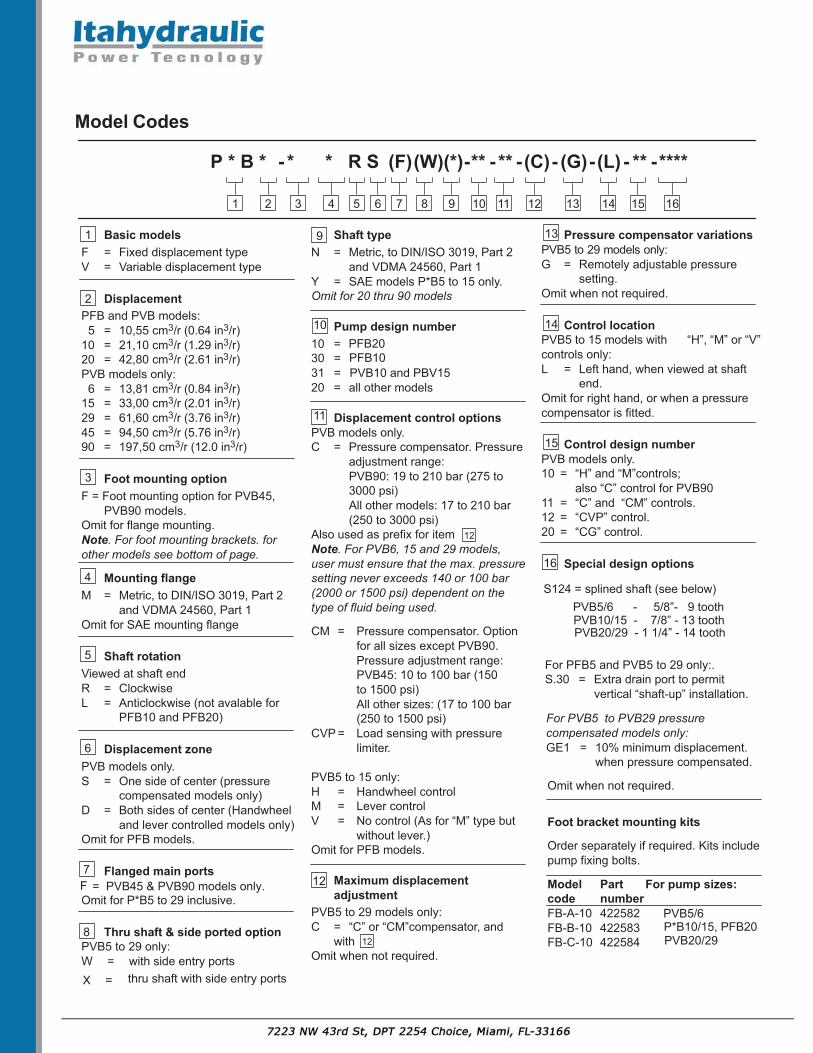
Model Codes
Basic modelsF = Fixed displacement typeV = Variable displacement type
DisplacementPFB and PVB models:
5 = 10,55 cm3/r (0.64 in3/r)10 = 21,10 cm3/r (1.29 in3/r)20 = 42,80 cm3/r (2.61 in3/r)PVB models only:
6 = 13,81 cm3/r (0.84 in3/r)15 = 33,00 cm3/r (2.01 in3/r)29 = 61,60 cm3/r (3.76 in3/r)45 = 94,50 cm3/r (5.76 in3/r)90 = 197,50 cm3/r (12.0 in3/r)
Foot mounting optionF = Foot mounting option for PVB45,
PVB90 models.Omit for flange mounting.Note. For foot mounting brackets. forother models see bottom of page.
Mounting flange M = Metric, to DIN/ISO 3019, Part 2
and VDMA 24560, Part 1Omit for SAE mounting flange
Shaft rotationViewed at shaft endR = ClockwiseL = Anticlockwise (not avalable for
PFB10 and PFB20)
Displacement zonePVB models only.S = One side of center (pressure
compensated models only)D = Both sides of center (Handwheel
and lever controlled models only)Omit for PFB models.
Flanged main portsFOmit for P*B5 to 29 inclusive.
Thru shaft & side ported optionPVB5 to 29 only:W = with side entry ports
1
P * B * * * R S (C)- (G) (L)
1 32 4 145 11
2
3
4
5
6
7
6 7
(*)
8
-**
9
- **
10
- -
12
-
13
- ** -****
16
Shaft typeN = Metric, to DIN/ISO 3019, Part 2
and VDMA 24560, Part 1Y = SAE models P*B5 to 15 only.Omit for 20 thru 90 models
Pump design number10 =30 =31 =20 = all other models
Displacement control optionsPVB models only.C = Pressure compensator. Pressure
adjustment range:PVB90: 19 to 210 bar (275 to 3000 psi)All other models: 17 to 210 bar (250 to 3000 psi)
Also used as prefix for itemNote. For PVB6, 15 and 29 models, user must ensure that the max. pressuresetting never exceeds 140 or 100 bar(2000 or 1500 psi) dependent on thetype of fluid being used.
CM = Pressure compensator. Option for all sizes except PVB90.Pressure adjustment range:PVB45: 10 to 100 bar (150 to 1500 psi)All other sizes: (17 to 100 bar (250 to 1500 psi)
CVP = Load sensing with pressure limiter.
PVB5 to 15 only:H = Handwheel controlM = Lever controlV = No control (As for “M” type but
without lever.)Omit for PFB models.
Maximum displacementadjustment
PVB5 to 29 models only:C = “C” or “CM”compensator, and
withOmit when not required.
12
9
10
11
Pressure compensator variationsPVB5 to 29 models only:G = Remotely adjustable pressure
setting.Omit when not required.
Control locationPVB5 to 15 models with “H”, “M” or “V”controls only:L = Left hand, when viewed at shaft
end.Omit for right hand, or when a pressurecompensator is fitted.
Control design numberPVB models only.10 = “H” and “M”controls;
also “C” control for PVB9011 = “C” and “CM” controls.12 = “CVP” control.20 = “CG” control.
Special design options
For PFB5 and PVB5 to 29 only:.S.30 = Extra drain port to permit
vertical “shaft-up” installation.
For PVB5 to PVB29 pressurecompensated models only:GE1 = 10% minimum displacement.
when pressure compensated.
Omit when not required.
Foot bracket mounting kits
Order separately if required. Kits includepump fixing bolts.
Model Part For pump sizes:code numberFB-A-10 422582FB-B-10 422583FB-C-10 42258412
12
13
14
15
16
(F)
8
(W)
15
X = thru shaft with side entry ports
= PVB45 & PVB90 models only.
PVB5/6P*B10/15, PFB20 PVB20/29
PFB20PFB10PVB10 and PBV15
S124 = splined shaft (see below)PVB5/6 - 5/8”- 9 toothPVB10/15 - 7/8” - 13 toothPVB20/29 - 1 1/4” - 14 tooth

Operating Data
Pressure and Speed Limits
Anti-wear Water-in– Water- Anti–wear Water Water-in–
hydraulic oil glycol hydraulic glycol oil
oil emulsion oil emulsion
(40%/60%) (40%/60%)
PFB5 10,55 (0.64) 3600 210 (3000)PFB10 21,10 (1.29) 3200 1800 1800 210 (3000) 175 (2500) 175 (2500)PFB20 42,80 (2.61) 2400 175(2500)
PVB5 10,55 (0.64) 210 (3000) 140 (2000) 140 (2000)PVB6 13,81 (0.84) 140 (2000) 100 (1500) 100 (1500)PVB10 21,10 (1.29) 210 (3000) 140 (2000) 140 (2000)PVB15 33,00 (2.01) 1800 1800 1800 140 (2000) 100 (1500) 100 (1500)PVB20 42,80 (2.61) 210 (3000) 140 (2000) 140 (2000)PVB29 61,60 (3.76) 140 (2000) 100 (1500) 100 (1500)PVB45 94,50 (5.76) 210 (3000) 140 (2000) 140 (2000)
PVB90 197,50 (12.0) 1800 1200 1200 210 (3000) 140 (2000) 140 (2000)
Maximum Inlet Pressure
All pumps except PVB5/6/10/15 with H, M or V controls 1,0 bar (15 psi). . . . . . . . . . . . . PVB5/6/10/15 with H, M or V controls As “Max. outlet pressure” above. . . . . . . . . . . . . .
for appropriate size.
Case Drain Pressure
See “Installation data” section, on page A.33.
Minimum Inlet Pressure
See following graphs.Based on oil viscosity of 21 cSt (102 SUS) and at 50 C (120 F).
0,6
0,8
1,0
1,2
1,4
1,6
1,8barpsi
10
20
30
15
25
Ab
so
lute
pressu
re
Su
perch
arg
e p
ressu
re
0,6
0,8bar
0,2
0,4
0
1200 24001800 36003000
Drive speed, r/min
PFB5 and PVB5
psi
10
0
5
Vacuum:170 m bar(5 Hg)
60000,6
0,8
1,0
1,2
1,4
1,6
1,8barpsi
10
20
30
15
25
Ab
so
lute
pressu
re
Su
perch
arg
e p
ressu
re
0,6
0,8bar
0,2
0,4
0
1200 240018003200
3000
Drive speed, r/min
psi
10
0
5
Vacuum:170 m bar(5 Hg)
6000
PVB6
Maximum shaft
speed (r/min)
Maximum outlet
pressure, bar (psi)
Basic model
designation
Geometric
displacement,
cm3/r (in3/r)
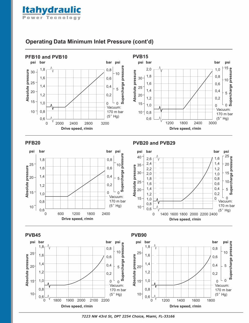
Operating Data Minimum Inlet Pressure (cont’d)
0,6
0,8
2,0
1,0
1,2
1,4
1,6
1,8
barpsi
10
20
30
15
25
Abs
olut
e pr
essu
re
Supe
rcha
rge
pres
sure
0,6
0,8
1,0
bar
0,2
0,4
0
3000Drive speed, r/min
PVB15psi
10
15
0
5
Vacuum:170 m bar(5 Hg)0,6
0,8
1,0
1,2
1,4
1,6
1,8
barpsi
10
20
30
15
25
Abs
olut
e pr
essu
re
Supe
rcha
rge
pres
sure
0,6
0,8
bar
0,2
0,4
0
2000 28002400 3200Drive speed, r/min
PFB10 and PVB10psi
10
0
5
Vacuum:170 m bar(5 Hg)
0,6
0,8
1,0
1,2
1,4
1,6
1,8
barpsi
10
20
15
25
Abs
olut
e pr
essu
re
Supe
rcha
rge
pres
sure
0,6
0,8
bar
0,2
0,4
0
0 600 1200 1800 2400Drive speed, r/min
PFB20psi
10
0
5
Vacuum:170 m bar(5 Hg)
0
0,60,8
2,0
1,01,21,41,61,8
2,22,42,6
barpsi
10
20
30
40
15
25
35
Abs
olut
e pr
essu
re
Supe
rcha
rge
pres
sure
0,60,81,01,21,41,6
bar
0,20,4
0
0 1600 2000 2400Drive speed, r/min
PVB20 and PVB29psi
10
20
15
25
0
5
Vacuum:170 m bar(5 Hg)
1800 22001400
1800 24001200
0,6
0,8
1,0
1,2
1,4
1,6
1,8barpsi
10
20
15
25
Abs
olut
e pr
essu
re
Supe
rcha
rge
pres
sure
0,6
0,8
bar
0,2
0,4
0
Drive speed, r/min
PVB45psi
10
0
5
Vacuum:170 m bar(5 Hg)
1800 22002000 2100190000,6
0,8
1,0
1,2
1,4
1,6
1,8barpsi
10
20
15
25
Abs
olut
e pr
essu
re
Supe
rcha
rge
pres
sure
0,6
0,8
bar
0,2
0,4
0
1200 1400 1800Drive speed, r/min
PVB90psi
10
0
5
Vacuum:170 m bar(5 Hg)
16000

0
200
400
0
60
20
40
60080
800
12345
0
20
0
10
5
15
With oil at 21cSt (102 SUS) and at 49 C (120 F): Atmospheric inlet
DeliveryEfficiency, %
0
20
40
60
80
100
00
Torque
5
10
100
200
300
400
0
10
20
L/min kW Nm lbf inhp
Input power
US gpm
10
5
0 0
10
20
30
40
Efficiency, %
0
20
40
60
80
100
Delivery
L/minUS gpm kW hp
Input power Torque
Nm lbf in
15
10
5
0
PFB10
15
5
25
PFB20
0
500
1000
1500
2000
0
10
20
30
Efficiency, %
0
20
40
60
80
100
Delivery
L/minUS gpm kW hp
Input power
15
10
5
0
20
Torque
Nm lbf in
0
50
100
150
200
250
246
810
0
20
40
0
10
30
0
10
20
204060
80
0
Outlet pressure0 500 1000 1500 2000 2500 3000 psi
0 100 210 bar50 150
Outlet pressure0 500 1000 1500 2000 2500 3000 psi
0 100 210 bar50 150
Outlet pressure0 500 1000 1500 2000 2500 psi
0 100 175 bar50 150
For data at drive speed of 1800 r/min, see pages A.11 toA.14
Performance Data at 1500 r/min Drive Speed
PFB5

With oil at 21cSt (102 SUS) and at 49 C (120 F): Atmospheric inlet
DeliveryEfficiency, %
0
20
40
60
80
100
00
Torque
5
10
100
200
300
400
0
0
10
20
30
L/min kW Nm lbf inhp
Input power
US gpm
10
5
0 0
10
20
30
40
Efficiency, %0
20
40
60
80
100
Delivery
L/minUS gpm
0
kW hp
Input power
5
0Torque
Nm lbf in
Efficiency, %
0
20
40
60
80
100
Delivery
L/minUS gpm kW hp
Input power Torque
Nm lbf in
15
10
5
20
PVB5
12345
1
2
1 = Delivery with compensator setting of 100 bar (1500 psi)2 = Delivery with compensator setting of 200 bar (3000 psi)
0
20
0
10
5
15
PVB6
2
4
6
1 = Delivery with compensator setting of 70 bar (1000 psi)2 = Delivery with compensator setting of 100 bar (1500 psi)3 = Delivery with compensator setting of 140 bar (2000 psi)
23
1
0
2
4
6
8
0
100
200
300
0
10
20
30
150
250
50
4
1
2
3
6
20
10
5
15
25
PVB10
2
46
1 = Delivery with compensator setting of 100 bar (1500 psi)2 = Delivery with compensator setting of 200 bar (3000 psi)
810
1
2
0
200
400
0
60
20
40
60080
800
15
5
25
0
20
40
0
10
30
Outlet pressure0 500 1000 1500 2000 2500 3000 psi
0 100 210 bar50 150
Outlet pressure0 500 1000 1500 2000 2500 3000 psi
0 100 210 bar50 150
Outlet pressure0 500 1000 1500 2000 psi
0 0 10 bar50 140
Performance Data at 1500 r/min Drive Speed (cont’d)
0
For data at drive speed of 1800 r/min, see pages A.11 to A.14

1
2
With oil at 21cSt (102 SUS) and at 49 C (120 F): Atmospheric inlet
PVB15
DeliveryEfficiency, %00
20
40
60
80
100
Torque
1 = Delivery with compensator setting of 50 bar (750 psi)2 = Delivery with compensator setting of 100 bar (1500 psi)
10
5
15
PVB20
PVB29
00
101 3
3 = Delivery with compensator setting of 175 bar (2500 psi)4 = Delivery with compensator setting of 200 bar (3000 psi)
24
20
500
1000
1500
1 = Delivery with compensator setting of 35 bar (500 psi)2 = Delivery with compensator setting of 100 bar (1500 psi)
0
105
152025
0
500
1000
1500
132
4
2000
2000
0
10
20
30
0
10
20
30
L/min kW Nm lbf inhp
Input power
US gpm
20
40
60
0
Efficiency, %
0
20
40
60
80
100
Delivery
L/minUS gpm
20
406080
0
kW hp
Input power
15
10
5
0
20
Torque
Nm lbf in
0
50
100
150
200
250
Efficiency, %
0
20
40
60
80
100
Delivery
L/minUS gpm kW hp
Input power Torque
Nm lbf in
40
80
0
100
60
20
15
10
5
0
20
0
50
100
150
200
250
Outlet pressure0 500 1000 1500 2000 2500 3000 psi
0 100 210 bar50 150
Outlet pressure0 500 1000 1500 2000 psi
0 0 10 bar50 140
Outlet pressure0 500 1000 1500 2000 psi
0 0 10 bar50 140
3 = Delivery with compensator setting of 175 bar (2500 psi)4 = Delivery with compensator setting of 200 bar (3000 psi)
1 = Delivery with compensator setting of 35 bar (500 psi)2 = Delivery with compensator setting of 100 bar (1500 psi)
00
6
10
100200
3004005008
0 0
60
20
40
60070080800
4
2
6 8
14
24
Performance Data at 1500 r/min Drive Speed (cont’d)
For data at drive speed of 1800 r/min, see pages A.11 to A.14

With oil at 21cSt (102 SUS) and at 49 C (120 F): Atmospheric inlet
0 0
1000
2000
0
Efficiency, %
0
20
40
60
80
100
Delivery
L/minUS gpm kW hp
Input power Torque
Nm lbf in
50
0
100
0
20
0
100
200
PVB45
10203040
20
40
60
300
4003000
40150
0 0
2000
0
Efficiency, %0
20
40
60
80
100
Delivery
L/minUS gpm kW hp
Input power Torque
Nm lbf in
100
0
200
0
25
0
200
PVB90
204060 400
400030080
255075100125
175
50
75
100
125
6000
8000
600
800
1000
1 2
1 = Delivery with compensator setting of 100 bar (1500 psi)2 = Delivery with compensator setting of 200 bar (3000 psi)
1 2
1 = Delivery with compensator setting of 100 bar (1500 psi)2 = Delivery with compensator setting of 200 bar (3000 psi)
Outlet pressure0 500 1000 1500 2000 2500 3000 psi
0 100 210 bar50 150
Outlet pressure0 500 1000 1500 2000 2500 3000 psi
0 100 210 bar50 150
8060
150
Performance Data at 1500 r/min Drive Speed (cont’d)
For data at drive speed of 1800 r/min, see pages A.11 to A.14

0
200
400
0
60
20
40
60080
800
123456
0
20
0
105
15
25
With oil at 21cSt (102 SUS) and at 49 C (120 F): Atmospheric inlet
DeliveryEfficiency, %
0
20
40
60
80
100
00
Torque
5
10
15
100
200
300
400
0
10
20
30
L/min kW Nm lbf inhp
Input power
US gpm
10
5
0 0
10
20
30
40
Efficiency, %
0
20
40
60
80
100
Delivery
L/minUS gpm kW hp
Input power Torque
Nm lbf in
15
10
5
0
20
25
PFB5
PFB10
15
5
25
35
PFB20
0
500
1000
1500
2000
0
10
20
30
Efficiency, %
0
20
40
60
80
100
Delivery
L/minUS gpm kW hp
Input power
15
10
5
0
20
25
Torque
Nm lbf in
0
50
100
150
200
250
2468
10
0
20
40
0
12
10
30
50
0
10
20
20406080
0
Outlet pressure0 500 1000 1500 2000 2500 3000 psi
0 100 210 bar50 150
Outlet pressure0 500 1000 1500 2000 2500 3000 psi
0 100 210 bar50 150
Outlet pressure0 500 1000 1500 2000 2500 psi
0 100 175 bar50 150
For data at drive speed of 1500 r/min, see pages A.7 to A.10

With oil at 21cSt (102 SUS) and at 49 C (120 F): Atmospheric inlet
DeliveryEfficiency, %
0
20
40
60
80
100
00
Torque
5
10
15
100
200
300
400
0
0
10
20
30
L/min kW Nm lbf inhp
Input power
US gpm
10
5
0 0
10
20
30
40
Efficiency, %0
20
40
60
80
100
Delivery
L/minUS gpm
0
kW hp
Input power
5
0Torque
Nm lbf in
Efficiency, %
0
20
40
60
80
100
Delivery
L/minUS gpm kW hp
Input power Torque
Nm lbf in
15
10
5
20
25
PVB5
123456
1
2
1 = Delivery with compensator setting of 100 bar (1500 psi)2 = Delivery with compensator setting of 200 bar (3000 psi)
0
20
0
105
15
25
PVB6
2
4
6
1 = Delivery with compensator setting of 70 bar (1000 psi)2 = Delivery with compensator setting of 100 bar (1500 psi)3 = Delivery with compensator setting of 140 bar (2000 psi)
8
23
1
0
2
4
6
8
0
100
200
300
0
10
20
30
150
250
50
4
123
6
20
10
5
15
25
30
PVB10
246
1 = Delivery with compensator setting of 100 bar (1500 psi)2 = Delivery with compensator setting of 200 bar (3000 psi)
810
1
2
0
200
400
0
60
20
40
60080
800
15
5
25
35
0
20
40
0
12
10
30
50
Outlet pressure0 500 1000 1500 2000 2500 3000 psi
0 100 210 bar50 150
Outlet pressure0 500 1000 1500 2000 2500 3000 psi
0 100 210 bar50 150
Outlet pressure0 500 1000 1500 2000 psi
0 0 10 bar50 140
107
Performance Data at 1800 r/min Drive Speed (cont’d)
0
For data at drive speed of 1500 r/min, see pages A.7 to A.10

1
2
With oil at 21cSt (102 SUS) and at 49 C (120 F): Atmospheric inlet
PVB15
DeliveryEfficiency, %00
20
40
60
80
100
Torque
1 = Delivery with compensator setting of 50 bar (750 psi)2 = Delivery with compensator setting of 100 bar (1500 psi)
10
5
15
20
PVB20
PVB29
00
101 3
3 = Delivery with compensator setting of 175 bar (2500 psi)4 = Delivery with compensator setting of 200 bar (3000 psi)
24
20
500
1000
1500
1 = Delivery with compensator setting of 35 bar (500 psi)2 = Delivery with compensator setting of 100 bar (1500 psi)
0
105
15202530
0
500
1000
1500
132
4
2000
2000
0
10
20
30
0
10
20
30
L/min kW Nm lbf inhp
Input power
US gpm
20
40
60
80
0
Efficiency, %
0
20
40
60
80
100
Delivery
L/minUS gpm
20406080
0
kW hp
Input power
15
10
5
0
20
25
Torque
Nm lbf in
0
50
100
150
200
250
Efficiency, %
0
20
40
60
80
100
Delivery
L/minUS gpm kW hp
Input power Torque
Nm lbf in
40
80
0
100120
60
20
15
10
5
0
20
25
0
50
100
150
200
250
Outlet pressure0 500 1000 1500 2000 2500 3000 psi
0 100 210 bar50 150
Outlet pressure0 500 1000 1500 2000 psi
0 0 10 bar50 140
Outlet pressure0 500 1000 1500 2000 psi
0 0 10 bar50 140
3 = Delivery with compensator setting of 175 bar (2500 psi)4 = Delivery with compensator setting of 200 bar (3000 psi)
1 = Delivery with compensator setting of 35 bar (500 psi)2 = Delivery with compensator setting of 100 bar (1500 psi)
00
6
10
16
100200
30040050010
8
0 0
60
20
40
60070080800
42
6 8
14
24
Performance Data at 1800 r/min Drive Speed (cont’d)
For data at drive speed of 1500 r/min, see pages A.7 to A.10
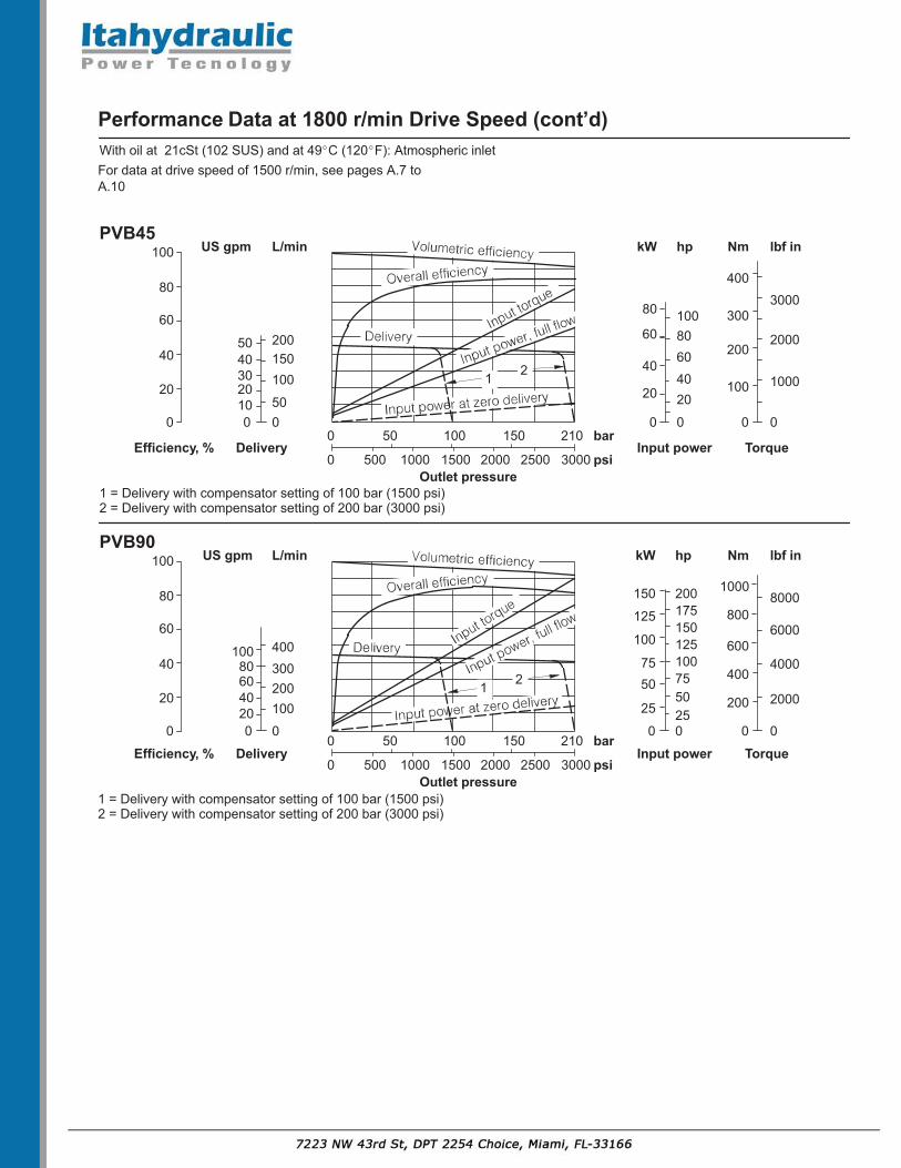
With oil at 21cSt (102 SUS) and at 49 C (120 F): Atmospheric inlet
0 0
1000
2000
0
Efficiency, %
0
20
40
60
80
100
Delivery
L/minUS gpm kW hp
Input power Torque
Nm lbf in
500
100
0
20
0
100
200
PVB45
1020304050
204060
300
4003000
40150200
0 0
2000
0
Efficiency, %0
20
40
60
80
100
Delivery
L/minUS gpm kW hp
Input power Torque
Nm lbf in
100
0
200
0
25
0
200
PVB90
204060 400
4000300400
80100
255075100125
175200
5075
100
125
150
6000
8000
600
800
1000
1 2
1 = Delivery with compensator setting of 100 bar (1500 psi)2 = Delivery with compensator setting of 200 bar (3000 psi)
1 2
1 = Delivery with compensator setting of 100 bar (1500 psi)2 = Delivery with compensator setting of 200 bar (3000 psi)
Outlet pressure0 500 1000 1500 2000 2500 3000 psi
0 100 210 bar50 150
Outlet pressure0 500 1000 1500 2000 2500 3000 psi
0 100 210 bar50 150
80100
60
80
150
Performance Data at 1800 r/min Drive Speed (cont’d)
For data at drive speed of 1500 r/min, see pages A.7 toA.10

Control Data for PVB Pumps
Controls available as indicated in “ModelCode” section.
“C” and “CM” Pressure
Compensators
Automatically adjusts pump delivery atpre-adjusted pressure to match systemdemand. Delivery can decrease rapidlyfrom maximum to zero through apressure gradient typically 4 to 6 bar (60to 90 psi) with normal circuit volumes.
For pressure adjustment ranges see“Model Code”.Note:
1. When using PVB6, 15 or 29 pumpswith “C” type compensators ther usermust ensure that the maximumpressure setting never exceeds 140or 100 bar (2000 or 1500 psi)dependent on the type of fluid beingused.
Caution. It is possible tomechanically adjust thecompensator up to 210 bar(3000 psi).
2. It is recommended that, as for othertypes of positive pump, a relief valveshould be fitted externally asprotection against overloads. Wherea relatively large amount of fluid isdirectly subject to compensatorpressure, it may be possible to omitthe relief valve.
“CC” and “CMC” Pressure
Compensators with Adjustable Max.
Displacement Stop
The pressure compensator sectionperforms as described above. Theadjustable stop allows the maximumpump delivery to be adjusted between25 to 100%. To assist priming, adjust thestop setting to provide at least 40% ofthe maximum displacement.
“CG” Pressure Compensator,
Remotely Controlled
Same as the “C” compensator, butarranged for remote pressureadjustment by suitable pilot controls.One or more pilot relief valves (e.g.C-175-*) and/or pilot directional valves,in series or in parallel, can provide manyvaried remote pilot systems.
“CV” Load Sensing Compensator,
Remotely Controlled
Automatically matches pump delivery tosystem demand at a pressureapproximately 17 bar (250 psi) aboveload pressure. This pressure differencecan be created by:– a variable flow restrictor (non-
compensated flow control) or thespool opening of a directional controlvalve.
Both forms can be used with fixed andvariable speed pump drives. In the lattercase a fixed restrictor can provide pre-set, near-constant pump flowindependent of drive speed, providedthat the speed exceeds that which givesthe required flow at full displacement. Anexternal pressure limiter must be addedto prevent overloading the pump; see“Functional Symbols” page A.3.
The matching of pump pressure anddelivery to system demands providespower matching and conservation byminimizing system power wastage.
“H” Handwheel Control
Provides manual variation or selection ofpump delivery. The control can beoperated on both sides of centerpermitting bi-directional flowcharacteristics.Approximate change of displacementper one turn of handwheel is:PVB5 2,6 cm3 (0.16 in3)PVB6 3,4 cm3 (0.21 in3)PVB10 5,2 cm3 (0.32 in3)
8,2 cm3 (0.5 in3)
“M” Lever Control
Provides mechanical or manual variationof pump delivery in approximateproportion to the angular movement fromthe center position. This control may beoperated on both sides of centerpermitting bi-directional flowcharacteristics. The pintle-mounted levercontrol must be secured by suitablelinkage to maintain desired settings;both extremes of pintle travel are limitedby internal stops to approx. 17.5 fromcenter.
Control torques (approx. at 1500 r/min).
(33 lbf in at 3000 psi)PVB6 2,7 Nm @ 138 bar
(24 lbf in at 2000 psi)
(66 lbf in at 1000 psi)
Note: Torque varies with pressure andspeed.
“GE1” Minimum Displacement
Control
Option for C(M)(C) and CG(C)compensators to limit the minimumdisplacement, in the fully compensatedmode, to nominally 10% of fulldisplacement.
Hydraulic Fluids
All pumps can be used with anti-wearhydraulic oils, water glycols andwater-in-oil (invert) emulsions. It ispossible to use these pumps with highwater base fluids (e.g. 5%/95%oil-in-water emulsion) at pressures up to70 bar (1000 psi).
The extreme operating viscosity rangeis from 220 to 13 cSt (1020 to70 SUS)for all pumps (except where 5%/95%emulsions are used). Therecommended running range is 54 to13 cSt. (245 to 70 SUS)
The viscosity of 5%/95% emulsions isnear-constant at about 1 or 2 cSt(<35 SUS).
7,5 Nm @ 70 barPVB10, PVB15
PVB5 3,8 Nm @ 210 bar
PVB15

Temperature LimitsMinimum ambient –20 C (–4 F). . . . . . . Maximum ambient. +70 C (+158 F). .
Fluid TemperaturesMineral Water-Mineraloil
Water-containing
Mininmum –20 C +10 C(–4 F) (+50 F)
Maximum* +80 C +54 C(+176 F) (+129 F)
* To obtain maximum service life from bothfluid and hydraulic system, 65 C (150 F)normally is the maximum temperature exceptfor water-containing fluids. Whatever theactual temperature range, ensure thatviscosities stay within the limits specified in“Hydraulic Fluids” section.
Drive Requirements:- Direction of RotationClockwise or anti-clockwise (viewed atshaft end) to order; see also “ModelCode”, and “Installation Dimensions”sections.
- Drive MethodsDirect co-axial drive through a suitableflexible coupling is preferred. If anindirect drive is to be used.
Filtration Requirements20/18/14 or ISO 18/14..
Noise Levels* Typical values equivalent to NFPA
Noise level – dB(A)*
Speed r/min Pressure bar (psi) Stroke PVB5 PVB6 PVB10 PVB15 PVB20 PVB29Full flow 51 52 54 58 – –
35 (500) Cutoff 51 51 44 47 – –Full flow 54 55 56 60 – –
70 (1000) Cutoff 52 54 49 54 – –1000 Full flow 56 57 60 62 – –
140 (2000) Cutoff 58 56 55 59 – –Full flow 60 – 61 – – –
210 (3000) Cutoff 59 – 59 – – –Full flow 50 51 55 60 – –
35 (500) Cutoff 52 51 48 51 – –Full flow 54 55 57 61 74 70
70 (1000) Cutoff 56 57 51 54 – –1200 Full flow 59 59 60 63 74 73
140 (2000) Cutoff 59 60 54 58 69 76Full flow 60 – 62 – 78 –
210 (3000) Cutoff 61 – 56 – – –Full flow 54 54 58 63 – –
35 (500) Cutoff 52 52 51 52 – –Full flow 58 58 60 64 – –
70 (1000) Cutoff 57 57 55 55 – –1500 Full flow 61 62 62 66 – –
140 (2000) Cutoff 62 59 62 59 – –Full flow 64 – 65 –– – –
210 (3000) Cutoff 62 – 63 –– – –Full flow 57 58 61 64 – –
35 (500) Cutoff 55 57 55 56 – –Full flow 60 61 63 67 76 77
70 (1000) Cutoff 59 58 59 60 – –1800 Full flow 63 66 65 69 81 81
140 (2000) Cutoff 62 63 62 64 75 81Full flow 64 – 67 – 81 –
210 (3000) Cutoff 64 – 65 – – –

Inlet/outlet ports:11/16 -12 UNF-2B thread for SAE O-ring fittings.
43,7(1.72)
A B
79,2(3.125)
127,0(5.0)152,4(6.0)
135 (5.3)
69,8(2.75)
106,4(4.19)
34(1.34)
12,7(0.5)
4 holes3/8 –16 UNC-2B thread(foot bracket)
4 holes Ø11,1(0.437 dia)
2 holesØ11,1 (0.437 dia)(pump flange)
Ø130(5.12 dia)
Case drain port 9/16 -18 UNF-2B forSAE O-ring fittings: 2 ports
Ø82,55/82,50(3.250/3.248 dia)
142,2 (5.6)85,9(3.4)
44,5(1.75)
Ø19,05/19,02(0.750/0.749 dia)
Key: 4,8 (0.19) Squarex 25,4 (1.0) long
12,7(0.5)
12,7(0.5)
32,5(1.28)59,4
(2.34)
50,8 (2.0)
12,7(0.5)
6,4(0.25)
57,2(2.25)
21,13/21,00(0.832/0.827)
PFB5 SAE Flange Mounting
Detail of shaft, key
and locating diameter
Optional foot bracket, shown in dashedoutline; kit FB-A-10 comprises footbracket and two pump fixing bolts.Order separately, if required.
View on rear end of pump
Installation Dimensions in mm (inches)
3rd angleprojection
Ø95,3(3.75 dia)
ROTATION
OUT IN
ROTATION
OUT
NI
98,6(3.9)
43,7(1.72)
47,3(1.86)
7,6(0.3)
103,1(4.06)
Alternatedrain port

View on rear end of pump
PFB10 SAE Flange Mounting
Ø101,60/101,55(4.000/3.998 dia)
Key:6,35 (0.25) Square 9,5
(0.375)
25,12/24,87(0.989/0.979)
2 holes in pump flange:Ø14,3 (0.563 dia)
B
Ø22,22/22,20(0.875/0.874 dia)
Case drain port 3/4 -16 UNF-2B for SAEO-ring fittings: 2 ports
45,7(1.80)
146(5.75)177,8(7.0)
Ø174,8(6.88 dia)
Ø120,6(4.75 dia)
Pump
type
A
PFB-*-30 44,4(1.75)
PFB10-*Y-30 58,7(2.31)
A B
62,0(2.44)
62,7 (2.47)
Inlet/outlet ports:15/8 -12 UNF-2B thread for SAE O-ring fittings.
ROTATION
OUT IN
114,3(4.5)
133,3 (5.25)
C
87,9(3.46)12,7(0.5)
A
D
E 50,8(2.0)
12,7(0.5)
98,6(3.9)
92,1
180,8(7.12)
4 holes:Ø11,2 (0.44 dia)
B
213,9(8.42)228,1(8.98)
C
33,3(1.31)47,6(1.87)
D*
26,9(1.06)41,1(1.62)
E*
59,4(2.34)73,7(2.9)
Detail of shaft, key
and locating diameter
Optional foot bracket, shown in dashedoutline; kit FB-B-10 comprises footbracket and two pump fixing bolts.Order separately, if required.
12,7(0.5) Alternative drain
port
Installation Dimensions in mm (inches)
*Omit for foot bracket models)

View on rear end of pump
PFB20 SAE Flange Mounting
Ø101,60/101,55(4.000/3.998 dia)
Key:7,9 (0.31) Square
35,33/35,08(1.391/1.381)
2 holesØ14,3 (0.56 dia)
130,0(5.12)
14,2(0.56)
262,9(10.32)
58,7(2.31)
Ø31,75/31,70(1.250/1.248 dia)
Case drain port 3/4 -16 UNF-2Bfor SAE O-ring fittings: 2 ports
43,7(1.72)
178,0(7.0)
Ø120,6(4.75 dia)
Shaft
rotation
Inlet
port
Outlet
port
RH B ALH A B
A B
82,5(3.25)
152,4 (6.0)73,2
(2.88)
Inlet/outlet ports (see table):15/8 -12 UNF-2B thread for SAE O-ring fittings.
146,0(5.75)171,4(6.75)
4 holesØ11,1(0.437 dia)
181,0(7.13)
92,1(3.63)
41,0(1.61)
50,8(2.0)
12,7(0.5)
12,7(0.5)
146,0(5.75)
47,8(1.88) 9,5
(0.375)
98,3(3.87)
73,6(2.9)
92,7(3.65)
144,3(5.7)
7,8(0.31)
Detail of shaft, key
and locating diameter
Optional foot bracket, shown in dashedoutline; kit FB-B-10 comprises footbracket and two pump fixing bolts.Order separately, if required.
Ø174,8(6.9 dia)
Alternativedrain port
R.H. Shaft Rotation
Installation Dimensions in mm (inches)

Compensator position for:R.H. rotation modelsL.H. rotation models
Caution: While pump is operating donot back compensator adjustmentscrew out beyond dimension shown.
Alternate drainport
Inlet/outlet ports (see table):11/16 -12 UNF-2B thread for SAE O-ring fittings.
38,1(1.50)
A B
79,4(3.125)
127,0(5.0)152,4(6.0)
135 (5.3) Heightof foot bracket
69,8(2.75)
106,4(4.19)
33,5(1.32)
12,7(0.5)
4 holes3/8 –16 UNC-2B thread(foot bracket)
4 holes Ø11,1(0.437 dia)
2 holesØ11,1 (0.437 dia)(pump flange)
Ø130(5.12 dia)
Case drain port 9/16 -18 UNF-2B forSAE O-ring fittings: 2 ports
Ø82,55/82,50(3.250/3.248 dia)
177 (6.9)
162,8 (6.41)
108,7 (4.23)69,8
(2.75)
44,4(1.75)
Ø19,05/19,02(0.750/0.749 dia)
Key: 4,8 (0.19) Squarex 25,4 (1.0) long
12,7(0.5)
50,8 (2.0)
12,7(0.5)
93 (3.7)
163,5 (6.44)
6,4(0.25)
84,8(3.34)
28,4(1.12)
79,2(3.12)
52,3(2.06)
135,9(5.35)
57,2(2.25)
Shaft
rotation
Inlet
port
Outlet
port
RH A BLH B A
21,13/21,00(0.832/0.827)
PVB5/6 SAE Flange Mounting:
Pressure Compensator Control - “C” and “CM”
View on rear end of pump
Detail of shaft, key
and locating diameter
Optional foot bracket, shown in dashedoutline; kit FB-A-10 comprises footbracket and two pump fixing bolts.Order separately, if required.
59,4(2.34)
R47,8(1.9 rad)
R20,6(0.8 rad)
R.H. Shaft
Rotation
Installation Dimensions in mm (inches)See also “Control Data” section, pageA.15.

PVB5/6 Thru-Shaft Models (with Side Ports)
177,0(6.97)
213,4(8.40)
153,2(6.03)
Ø15,82/15,8(0.623/0.622 dia)
17,91/17,78(0.705/0.700)
29,5(1.16)
165,1(6.50)
73,15(2.88)
51,3(2.02)
BA
Inlet port for RH rotation models;Outlet port for LH rotation models:15/16 -12 UN-2B thread for SAE O-ring fittings.
Outlet port for RH rotation models;Inlet port for LH rotation models:15/16 -12 UN-2B thread for SAE O-ring fittings.
4,77/4,75 (0.188/0.187)square key both ends
For other dimensions and installationdata see page A.20.
Maximum output torque is 40 Nm (354lbf in), less unput torque at systempressure, see performance curves:At 1500 r/min drive speed, page A.8.At 1800 r/min drive speed, page A.12.
Installation Dimensions in mm (inches)
153,2(6.03)
165,1(6.50)
BA
Inlet port for RH rotation models;Outlet port for LH rotation models:15/16 -12 UN-2B thread for SAE O-ring fittings.
Outlet port for RH rotation models;Inlet port for LH rotation models:15/16 -12 UN-2B thread for SAE O-ring fittings.
PVB5/6 (with Side Ports only)

12,7 (0.5)
Alternative drain port
28,4(1.12)
View on rear end of pump
PVB10/15 SAE Flange Mounting
Pressure Compensator Control - “C” and “CM”
Ø101,60/101,55(4.000/3.998 dia)
Key: 6,4 (0.25) Squarex 22,3 (0.88) long 9,5
(0.375)
25,12/24,87(0.989/0.979)
2 holesØ14,3(0.563 dia)
123,7(4.87)
74,7(2.94)
207,8(8.18)
12,7(0.5)
193,8(7.63)
58,7(2.31)
Ø22,22/22,20(0.875/0.874 dia)
47,8(1.88)
Case drain port .750-16 UNF-2B forSAE O-ring fittings: 2 ports
Compensator position for:R.H. rotation modelsL.H. rotation models
45,7(1.80)
146(5.75)187
(7.36)
Ø174,8(6.88 dia)
Ø120,6(4.75 dia)
Caution: While pump is operating donot back compensator adjustmentscrew out beyond dimension shown.
Shaft
rotation
Inlet
port
Outlet
port
RH A BLH B A
A B
66,5(2.62)
23,9(0.94)
84,8(3.34)
137,1(5.4) max
89,3(3.5) max
52,3 (2.1)
28,4 (1.12)
82,5 (3.25)
65 (2.56)
Inlet/outlet ports (see table):1.625-12 UN-2B thread for SAE O-ring fittings.
98,6(3.9)
92,1(3.63)
174,6(6.9)
12,7(0.5)
4 holesØ11,2 (0.44 dia)
41,1(1.62)
73,7(2.9)
50,8 (2.0)
Detail of shaft, key
and locating diameter
Optional foot bracket, shown in dashedoutline; kit FB-B-10 comprises footbracket and two pump fixing bolts.Order separately, if required.
189,0(7.44)
See also “Control Data” section, pageA.15.
Installation Dimensions in mm (inches)
R.H. Shaft
Rotation
.500-13 UNC-2Bthd. 4 holes

PVB10/15 Thru-Shaft Models (with Side Ports)
Ø19,05/19,02(0.750/0.749 dia)
21,13/21,00(0.832/0.827)
4,79/4,76 (0.1885/0.1875)square key x 25,4 (1.0) long
31,75 (1.25)
For other dimensions and installationdata see page A.22.
90,4(3.56)
65,3(2.57)
174,5(6.87)
308,8(12.16)
BA
Inlet port for RH rotation models;Outlet port for LH rotation models:15/8 -12 UN-2B thread for SAE O-ring fittings.
Outlet port for RH rotation models;Inlet port for LH rotation models:15/8 -12 UN-2B thread for SAE O-ring fittings.
196,9(7.75)
Maximum output torque is 83 Nm (735 lbfin), less unput torque at system pressure,see performance curves:At 1500 r/min drive speed, pages A.8 &A.9.At 1800 r/min drive speed, page A.12 &A.13.
174,5(6.87)
BA
Inlet port for RH rotation models;Outlet port for LH rotation models:
15/8
-12 UN-2B thread for SAE O-ring fittings.
Outlet port for RH rotation models;Inlet port for LH rotation models:15/8 -12 UN-2B thread for SAE O-ring fittings.
196,9(7.75)
PVB10/15 (with Side Ports only)

A B
Shaftrotation
Leverposition
Outletport
RH 1 A2 B
PVB5/6 and PVB10/15 Manual/Mechanical Controls
127(5.0)
76,2 (3.0)
35
R 9,7(0.38 rad)
6,4(0.25)
15,7(0.62)
A
B
Ø17,40/17,27(0.685/0.680 dia)
Ø6,4(0.25 dia)
2 n o i t i s o P1 n o i t i s o P
LH 1 B2 A No Control - “V”
Lever Control - “M” and No Control - “V”
Handwheel Control - “H”
Pumptype
A B
PVB5/6 153(6.02)
68,9(2.7)
PVB10/15 204(8.04)
99,9(3.93)
A B
Ø57,2(2.25 dia)15,7
(0.62)
37,3 (1.47)
65,7(2.6)
Position 1
Position 2
Max. flow adjustment.Adjust and lockto limit max. flow.
A
B
CR24
(0.95 rad)Ø6,3(2.25 dia)
62 (2.5 )max.
43,7(1.72 )
35,3 (1.39)
Caution!Loosen lock screw before
turning handle.Re-tighten afteradjusting flow.
Units with this control may be operated onboth sides of center permitting bi-directionalfluid flow characteristics.
Pumptype
A B
PVB5/6(7.87)
129(5.08)
PVB10/15(9.84)
140(5.51)
C
70,6(2.78)93,5(3.68)
Shaftrotation
Handwheelrotation from zero
Outletport
RH Clockwise ACounter-clockwise B
LH BA
Pointerposition1212
ClockwiseCounter-clockwise
Lever may be set atany position in 360circle. Ensure clampbolt is fully tightened.
Units with this control may be operated onboth sides of center permitting bi-directionalfluid flow characteristics.
200
250

Alternative drain port
28,4(1.12)
View on rear end of pump
PVB20/29 SAE Flange Mounting
Pressure Compensator Control - “C” and “CM”
Ø127,00/126,95(5.000/4.998 dia)
Key: 7,9 (0.31) Squarex 31,7 (1.25) long
35,33/35,08(1.391/1.381)
2 holesØ17,5 (0.69 dia)
123,4(4.86)84,8
(3.44)
295,0(11.62)
15,7(0.62)
221,7(8.73)
58,9(2.32)
Ø31,75/31,70(1.250/1.248 dia)
47,7(1.88)
Case drain port .750-16 UNF-2Bfor SAE O-ring fittings: 2 ports
53,8(2.1)
181,0(7.125)
226,0(8.9)
Ø146,0(5.75 dia)
Caution: While pump is operating donot back compensator adjustmentscrew out beyond dimension shown.
Shaft
rotation
Inlet
port
Outlet
port
RH A BLH B A
A B
82,5(3.25)
41,1 (1.62)
84,8 (3.34)
66,5 (2.62)95,2 (3.75)
59,2 (2.3)
Inlet/outlet ports (see table):1.625-12 UNF-2B thread for SAE O-ring fittings.
234,9(9.25)265,2(10.5)
50,8(2.0)
4 holesØ17,5(0.69 dia)
215,9(8.5)
109,5(4.31)
39,9(1.6)
19,0(0.75) 76,2 (3.0)
17,3 (0.68)
128,5(5.1)
50,8(2.0)
15,7(0.62)
189,0(7.44)
Detail of shaft, key
and locating diameter
Optional foot bracket, shown in dashedoutline; kit FB-C-10 comprises footbracket and two pump fixing bolts.Order separately, if required.
Ø212,8(8.38 dia)
See also “Control Data” section, pageA.15.
Installation Dimensions in mm (inches)
R.H. Shaft
Rotation
9,5(0.37)

PVB20/29 Thru-Shaft Models (with Side Ports)
For other dimensions and installationdata see page A.25.
306,1(12.05)
35,7(1.406)
Ø25,37/25,35(0.999/0.998 dia)
29,96(1.14)
Key: 6,35 (0.25) squarex 25,4 (1.0) long
69,85(2.75)
365,25(14.38)
235,7(9.28)
277,1(10.91)
.500-13 UNC-2B thread 8 placesfor 11/2 SAE 4-bolt flange
Ø38,1(1.50 dia)
111,2(4.38)
148,8(5.86)
260,0(10.24)
58,9 (2.32) min.
93,2(3.67)
85,3(3.36)
A
B
Port A:Inlet port for RH rotation models.Outlet port for LH rotation models.
Port B:Outlet port for RH rotation models.Inlet port for LH rotation models.
Maximum output torque is 159 Nm(1408 lbf in), less unput torque atsystem pressure, see performancecurves:
At 1500 r/min drive speed, page A.9At 1800 r/min drive speed, page A.13
35,7(1.406)
69,85(2.75)
235,7(9.28)
277,1(10.91)
.500-13 UNC-2B thread 8 placesfor 11/2 SAE 4-bolt flange
Ø38,1(1.50 dia)
148,8(5.86)
260,0(10.24)
93,2(3.67)
85,3(3.36)
A
B
Port A:Inlet port for RH rotation models.Outlet port for LH rotation models.
Port B:Outlet port for RH rotation models.Inlet port for LH rotation models.
PVB20/29 (with Side Ports only)

PVB45 Flange-Mounted Model
15,75(0.62)
290(11.42)
OUT
IN
407,0(16.0)
299,0(11.77)
81,79(3.22)
66,67 (2.625)
308,0(12.13)
141,0(5,55)
161,6(6,34)square
Ø152,4/152,35(6,000/5.998 dia)
Ø44,45/44,40(1.750/1.748 dia)
49,43(1.945/1.935)
200,2 (7,88)square
View on shaft end of pump View on rear end of pump
Key11,1 (0.437) square
4 slots 19,8 (0.78) wide formounting bolts. (Use of backingwashers is recommended)
127,0(5.0)
42,9 (1.688)
77,8(3.062)
101,6(4.0)
To suit SAE 4-bolt port flanges:8 holes .500–13 UNC 2B threadx 27,0 (1.06) deep
2 ports Ø50,8(2.0 dia)
Alternative drain port.
CAUTION:While pump is operating do not
back compensator adjusterscrew out beyond thisdimension.
35,0(1.38)
Direction ofshaft rotation
.3750-16 UNC 2B thread x12,0 (0.47) deep for liftingeye-bolt.
38,1 (1.5)
Drain connection: 1.0625-12 UNF 2Bthread for SAE O-ring fittings (2 ports).
Compensator adjuster: 38,1 (1.5) A/F hex.
145,3(5.72)
187,4(7.38)
110,3(4.34)
312 4(12.3)
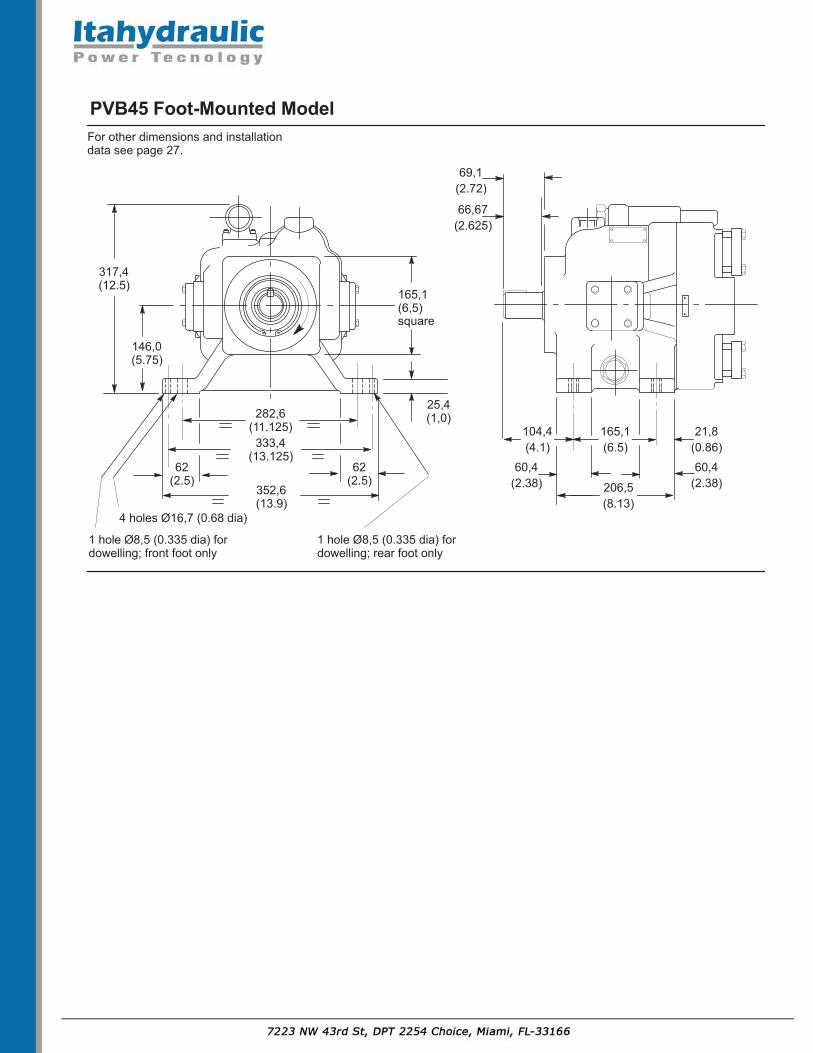
PVB45 Foot-Mounted Model
317,4(12.5)
66,67(2.625)
146,0(5.75)
165,1(6,5)square
69,1(2.72)
352,6(13.9)
333,4(13.125)
282,6(11.125)
62(2.5)
62(2.5)
25,4(1,0)
104,4(4.1)
165,1(6.5)
206,5(8.13)
60,4(2.38)
60,4(2.38)
21,8(0.86)
1 hole Ø8,5 (0.335 dia) fordowelling; rear foot only
4 holes Ø16,7 (0.68 dia)
1 hole Ø8,5 (0.335 dia) fordowelling; front foot only
For other dimensions and installationdata see page 27.

PVB90
190,5(7.5)
365(14.4)
329(12.95)
351,5(13.84)
139,7(5,5)
Ø152,4/152,35(6,000/5.998 dia)
Ø44,45/44,40(1.750/1.748 dia)
49,40/49,15(1.945/1.935)
200(7,9)
square
View on shaft end of pump
View on rear end of pump
Key 11,1 (0.437) squarex 44,5 (1.75) long
139,7(5.5)
50,8(2.0)
To suit SAE 4-bolt port flanges:8 holes .500-13 UNC 2B thread x 27,0 (1.06) deep
2 portsØ60,4 (2.4 dia)
Drain connection:1.3125-12 UN 2B thread for SAEO-ring fittings (2 ports).
CAUTION:While pump is operating do not
back compensatoradjuster screw out beyondthis dimension.
35,0(1.38)
68,25(2.69)
156,5(6.16)
396,7(15.62)
163,8(10.24)
167,6(10.48)
Ø228,6 (9.0 dia) 4 holes Ø20,6 (0.81 dia) at 45 fromvertical/ horizontal center lines.
Compensator adjuster: 38,1 (1.5) A/F hex.
393,7(15.5)438,1
(17.25)
88,9(5.5)
111,2 (4.38)
12,7(0.5)
38,1(1.5)
215,9(8.5)
79,2(3.12)
130,0(5.12) 260,3
(10.25)187,5(7.38)
4 holes Ø16,7 (0.66 dia)
Shaftrotation
Inletport
Outletport
RH A BLH B A
Location of tappings for liftingeye-bolts,: 2 at shaft end; 1 at rear:.3750-16 UNC 2B thread x 12,0 (0.47)deep.
Foot mounting option (designated byModel Code = “F”) is shown in dottedoutline. An alternative base mountingfacility is provided by four tapped holesin the bottom face of the pump - seepage A.30.
center line todrain port
63,5(2.5)
127,0 (5.0)
A B
Drain connection:1.3125-12 UN 2B thread
130,2(5.125)
212,7(8.375)
4 holes tapped .6250-12UNC-2B x 28 (1.1) deep
Shaft endof pump
Detail of tappings in base of pump.

Caution: While pump is operating donot back compensator adjustmentscrew out beyond dimension shown.
A B
A Fully extended
EFB
D CG
17,3(0.68)
Adjusting rodMinimum delivery position (screw flushwith nut); do not adjust below flush. Note.
Compensator position for:PVB5/6-*RSY (RH rotation models) andPVB10/15 -*LSY (LH rotation models)
Note.Compensator position for:PVB5/6-*LSY (LH rotation models) andPVB10/15 -*RSY (RH rotation models)PVB20/29 -**SY (RH and LH rotation models)
28,4(1.12)
Pumptype
A B
PVB5/6 233(9.17)
195(7.68)
PVB10/15 266(10.47)
226(8.9)
C D
50(1.97)
22,9(0.9)
52,3(2.06)
25,1(0.99)
E
76,2(3.0)118(4.65)
F G
94,4(3.72)
94,4(3.72)
70,8(2.79)
90,2(3.55)
PVB5/6, PVB 10/15 and PVB20/29 with Pressure Compensatorand Adjustable Maximum Displacement Stop:Control Types “CC” and “CMC”
28,4(1.12)
H
H
_
23,8(0.94)
PVB20/29 294(11.56)
254(10.0)
66,5(2.62)
41,9(1.65)
_ 53,3(2.1)
104,4(4.11)
41,1(1.62)
For general dimensions andinstallation data of these pumps,see pages A.20, A.22 and A.25
23.9(0.94A/F

45,0(1.77)
.4375-20UNF-2B thread for SAE“CG” control models, connect toexternal valve.Note. Do not operate pump withthis port plugged.
Location as shown for:PVB5/6 LH rotation models,PVB10/15 RH rotation models andPVB20/29 LH and RH rotation models.
Location as shown in dotted outline for:PVB5/6 RH rotation models andPVB10/15 LH rotation models.
Caution: Effective compensator setting will be compensator control setting
plus remote relief valve setting.
Adjustment procedure1. Turn remote pressure control
(such as C-175) anti-clockwise to minimum setting.
2. Turn compensator adjustment plugto desired minimum pressure - 17 bar (250 psi) or higher.
3. Full pressure range can now be obtained with remote pressure control.
Type “GEVS”
Ø35 (1.4 dia)
40,69(1.6)
“CVP” Load Sensing with Pressure Limiter
55,0(2.17)
45,5(1.8)
22,0(0.87)
19,0 (0.75)
Ø28,5(1.12 dia)
Load sensing control port:.4375-20 UNF-2B threadfor SAE O-ring fittings.
Location as shown for:PVB5/6 LH rotation models,PVB10/15 RH rotation models andPVB20/29 LH and RH rotation models.
to mountingface PVB5/6 191 (7.51). . . . . . . . . . . . . .
PVB10/15 222 (8.75). . . . . . . . . . . PVB20/29 250 (9.84). . . . . . . . . . .
74,6(2.94)
43(1.7)
A
Pumptype
APort tapping
PFB5 .562518UNF-2B
PVB5/6
Additional drain port
.5625 18UNF-2BPVB10/15 29,3 (1.15).7500 16UNF-2BPVB20/29 38,9 (1.53).7500 16UNF-2B
Vertical “Shaft-up” Installation - “S30” Drain PortOption for PVB5 to 29
PVB5 to 29 with “CG” Remote Control of Compensator
28,7 (3.85)
19 (0.75)

109,0(4.29)
2 holesØ11,3 (0.44 dia)
44,5 (1.75)
Ø80,0(3.15 dia)
PVB5/6; PVB10/15; PVB20/29 – DIN/ISO Models
7,24 (0.285)
Ø20,0(0.787 dia)
22,5 (0.886)
Key: 6,0 (0.236) squarex 22,5 (0.89) long
2 holesØ14,25(0.56 dia)
140(5.51)
52,5 (2.07)
Ø100,0(3.937 dia)
9,24 (0.364)
Ø25,0(0.984 dia)
28,0 (1.1)
Key: 8,0 (0.315) squarex 28,0 (1.1) long
36,0(1.42)
42,0 (1.65)
2 holesØ18,25 (0.72 dia)
180,0(7.08)
68,9 (2.71)
Ø125,0(4.92 dia)
9,24 (0.364)
Ø32,0(1.26 dia)
35,0 (1.38)
Key: 10,0 (0.39) squarex 35,0 (1.38) long
58,0(2.28)
For dimensions/data not shown refer to corresponding SAE models.
PVB5/6 – Pressure Compensated Control – “C” and “CM”
PVB10/15 – Pressure Compensated Control – “C” and “CM”
PVB20/29 – Pressure Compensated Control – “C” and “CM”
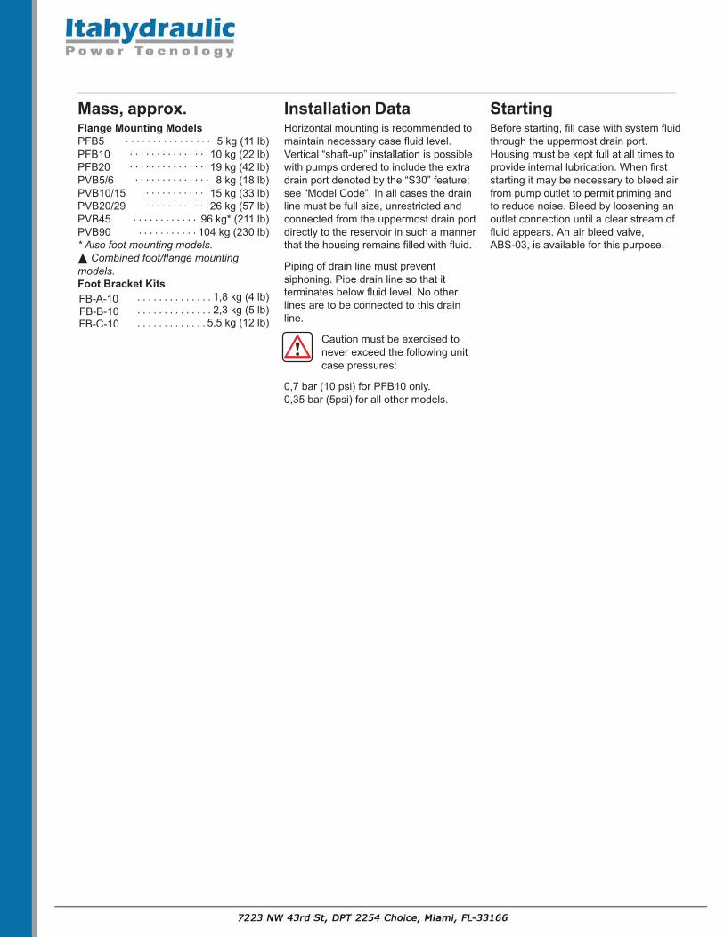
Mass, approx.
Flange Mounting Models
PFB5 5 kg (11 lb). . . . . . . . . . . . . . . . PFB10 10 kg (22 lb). . . . . . . . . . . . . . PFB20 19 kg (42 lb). . . . . . . . . . . . . . PVB5/6 8 kg (18 lb). . . . . . . . . . . . . . PVB10/15 15 kg (33 lb). . . . . . . . . . . PVB20/29 26 kg (57 lb). . . . . . . . . . . PVB45 96 kg* (211 lb). . . . . . . . . . . . PVB90 104 kg (230 lb). . . . . . . . . . . * Also foot mounting models.
Combined foot/flange mountingmodels.Foot Bracket Kits
FB-A-10 1,8 kg (4 lb) . . . . . . . . . . . . . . FB-B-10 2,3 kg (5 lb) . . . . . . . . . . . . . . FB-C-10 5,5 kg (12 lb) . . . . . . . . . . . . .
Installation Data
Horizontal mounting is recommended tomaintain necessary case fluid level.Vertical “shaft-up” installation is possiblewith pumps ordered to include the extradrain port denoted by the “S30” feature;see “Model Code”. In all cases the drainline must be full size, unrestricted andconnected from the uppermost drain portdirectly to the reservoir in such a mannerthat the housing remains filled with fluid.
Piping of drain line must preventsiphoning. Pipe drain line so that itterminates below fluid level. No otherlines are to be connected to this drainline.
Caution must be exercised tonever exceed the following unitcase pressures:
0,7 bar (10 psi) for PFB10 only.0,35 bar (5psi) for all other models.
Starting
Before starting, fill case with system fluidthrough the uppermost drain port.Housing must be kept full at all times toprovide internal lubrication. When firststarting it may be necessary to bleed airfrom pump outlet to permit priming andto reduce noise. Bleed by loosening anoutlet connection until a clear stream offluid appears. An air bleed valve,ABS-03, is available for this purpose.