PV016 PV020 PV023 PV032 PV040 PV046 - kstci.com.t · PDF...
24
KINGSTONE COMPONENT INC. is the world’s premier supplier of motion and control systems and solutions, with sales and manufacturing facilities throughout the world. For product information and details of your nearest KINGSTONE sales office, visit us at http://www.kstci.com.tw/ or [email protected] or +886 2 8732-8566 Catalog KSTCI © Copyright 2007 KINGSTONE COMPONENT INC. All rights reserved. PV016、PV020、PV023、PV032、PV040、PV046
Transcript of PV016 PV020 PV023 PV032 PV040 PV046 - kstci.com.t · PDF...

KINGSTONE COMPONENT INC. is the world’s premier supplier of motion and control systems and solutions, with salesand manufacturing facilities throughout the world. For product information and details of your nearest KINGSTONE salesoffice, visit us at http://www.kstci.com.tw/ or [email protected] or +886 2 8732-8566 Catalog KSTCI © Copyright 2007 KINGSTONE COMPONENT INC. All rights reserved.
PV016、PV020、PV023、PV032、PV040、PV046

Axial Piston PumpSeries PV
� Parker HannifinPump and Motor DivisionChemnitz, Germany
Catalogue HY30-3�45/UK
Contents Page
Introduction and general Information ..............................................................3
Technical Data ................................................................................................3
Technical Features .........................................................................................3
Ordering Code .............................................................................................4-5
Noise Levels ...................................................................................................6
Efficiency and Case Drain Flows .................................................................7-8
Dimensions ................................................................................................9-1�
Mounting kits ................................................................................................13
Pump combinations
Thru Drive, Shaft Load Limitations .....................................................14
Compensators
Compensator Dimensions ..................................................................15
Pressure Compensators ...............................................................16-17
Power Compensators .........................................................................18
Power Compensators .........................................................................19
Electrohydraulic p/Q control ...............................................................�0
Electronic Module PQDXXA (digital) ..................................................�1
Control Module Programming ............................................................��

Axial Piston PumpSeries PV
3 Parker HannifinPump and Motor DivisionChemnitz, Germany
Catalogue HY30-3�45/UK
With thru drive for single and multiple pumpsSwash plate type for open circuit
Introduction
Technical Features• Low noise level• Fast response
(eg. PV046: upstroke <70ms, downstroke <40ms)• Service-friendly• High self-priming speed• Compact design• Thru drive for 100% nominal torque
Technical DataSize PV016 PV020 PV023 PV032 PV040 PV046Max. Displacement [cm3/rev.] 16 �0 �3 3� 40 46 Output flow at 1500 min-1 [l/min] �4 30 34,5 48 60 69 Nominal pressure pN [bar] 350 350 350 350 350 350 Max. pressure pmax 1) [bar] 4�0 4�0 4�0 4�0 4�0 4�0 Max. Case drain pressure [bar] � � � � � � Min. Inlet pressure [bar] 0,8 0,8 0,8 0,8 0,8 0,8 Max. Inlet pressure [bar] 16 16 16 16 16 16 Input power at 1500 min-1 and 350 bar [kW] 15,5 19,5 ��,5 31 39 45 Max speed �) [min-1] 3000 3000 3000 �800 �800 �800 Moment of inertia [kgm�] 0,0017 0,0017 0,0017 0,0043 0,0043 0,0043 Weight [kg] 19 19 19 30 30 30
1) Maximum �0% of the working cycle.�) The maximum speed ratings are shown for an inlet pressure of 1 bar (absolute) and for a fluid viscosity of
ν= 30 mm�/s
General InformationFluid recommendationsPremium quality hydraulic mineral fluid are recommen-ded, like HLP oils to DIN 515��, part �.
ViscosityThe normal operating viscosity should range between 16 and 100 mm�/s (cSt). Max. start-up viscosity is 800 mm�/s (cSt).
SealsNBR (nitrile) seals are used for operation with hydraulic fluids based on mineral oil. For synthetic fluids, such as phosphoric acid esters, Flourocarbon seal are required.
FiltrationFor maximum pump and system component functio-nability and life, the system should be protected from contamination by effective filtration.Fluid cleanliness should be in accordance with ISO classification ISO 4406:1999. The quality of filter ele-ments should be in accordance with ISO standards.Minimum requirement for filtration rate x (mm);General hydraulic systems for satisfactory operation: Class �0/18/15, according to ISO 4406:1999Hydraulic systems with maximised component life and functionability:Class 18/16/13, according to ISO 4406:1999

Axial Piston PumpSeries PV
4 Parker HannifinPump and Motor DivisionChemnitz, Germany
Catalogue HY30-3�45/UKOrdering Code
metr. ISO3019/2
code thru drive option
no thru drive adapter
T single pump, pre- pared for thru drive
with thru drive adapter
Y3) SAE AA, Ø 50.8 mm
A SAE A, Ø 8�.55 mm
B SAE B, Ø 101.6 mm
C4) SAE C, Ø 1�7 mm
G metric, Ø 63 mm
H metric, Ø 80 mm
J metric, Ø 100 mm
K4) metric, Ø 1�5 mm
code mounting interface shaft
K 4-hole flange cylindric, key L 4-hole flange splined, DIN 5480
code variation
1 standard
P Vaxial piston
pump variable
displacement high
pressureversion
compensatorpumpsize and
displacement
coupling code
compensator
see next page
variation threadscode
design series:
not requiredon order
code rotation
R clockwise
mounting interface
thru drivecode
code ports1) threads�)
1 BSPP metrisch
code thru drive coupling option
1 single pump, no coupling H with coupling �5 x 1,5 x 15, DIN 5480
J with coupling 3� x 1,5 x �0, DIN 5480
Y with SAE coupling 9T-16/3� DP
A with SAE coupling 11T-16/3� DP
B with SAE coupling 13T-16/3� DP
C with SAE coupling 15T-16/3� DP
D with SAE coupling 14T-1�/�4 DP
1) refers to drain, gage and flushing port,�) refers to all mounting threads
rotation
code material
N NBR (nitrile)
bold letters = preferred program
1R 1seals
N
code displacement
016 16 cm³/rev 020 20 cm³/rev 023 23 cm³/rev 032 32 cm³/rev 040 40 cm³/rev 046 46 cm³/rev
See dimensional drawing for details3) only for PV016 - PV0�3 4) only for PV03� and larger

Axial Piston PumpSeries PV
5 Parker HannifinPump and Motor DivisionChemnitz, Germany
Catalogue HY30-3�45/UKOrdering Code
displacement code compensator style power control
016 032 nominal power at 1.500 rev/min 023 046
B 3 kW
C 4 kW
D 5,5 kW E 7,5 kW G 11 kW H 15 kW K 18,5 kW M �� kW S 30 kW
function
L power control C power control and load sensing
compensator version
C integrated, adjustable pressure compensation
1 topside NG6 / CETOP 3 interface
compensatornot required on orderpump
P Vcompensator design series:
code compensator style
electro hydraulic control
F P V closed loop displacement control only, no pressure compensation
function
U P closed loop proportional displacement control with pressure compensation
compensator version
R remote pressure compensation, NG6 /CETOP 3 interface for pilot valves
D version UPR, with proportional pilot valve type PVACPPU..35 mounted
G version UPD, with pressure sensor for closed loop pressure and power control
Note:
Compensator differential ∆p is factory pre-set to:
remote comepnsators, power control 15 ± 1 bar
load sensing comp. (not power control) 10 ± 1 bar (codes ...MF*)
code compensator style
0 0 1 no compensator
compensator version
M M standard pressure compensator, no control port
M R remote pressure compensator, control port on compensator body side
M F flow (load sensing) compensator, load sensing port on compensator body side
compensator variation
C standard variation, no topside interface for pilot valves
1 topside NG6 /CETOP 3 interface for pilot valves
Axial Piston PumpSeries PV
6 Parker HannifinPump and Motor DivisionChemnitz, Germany
Catalogue HY30-3�45/UK
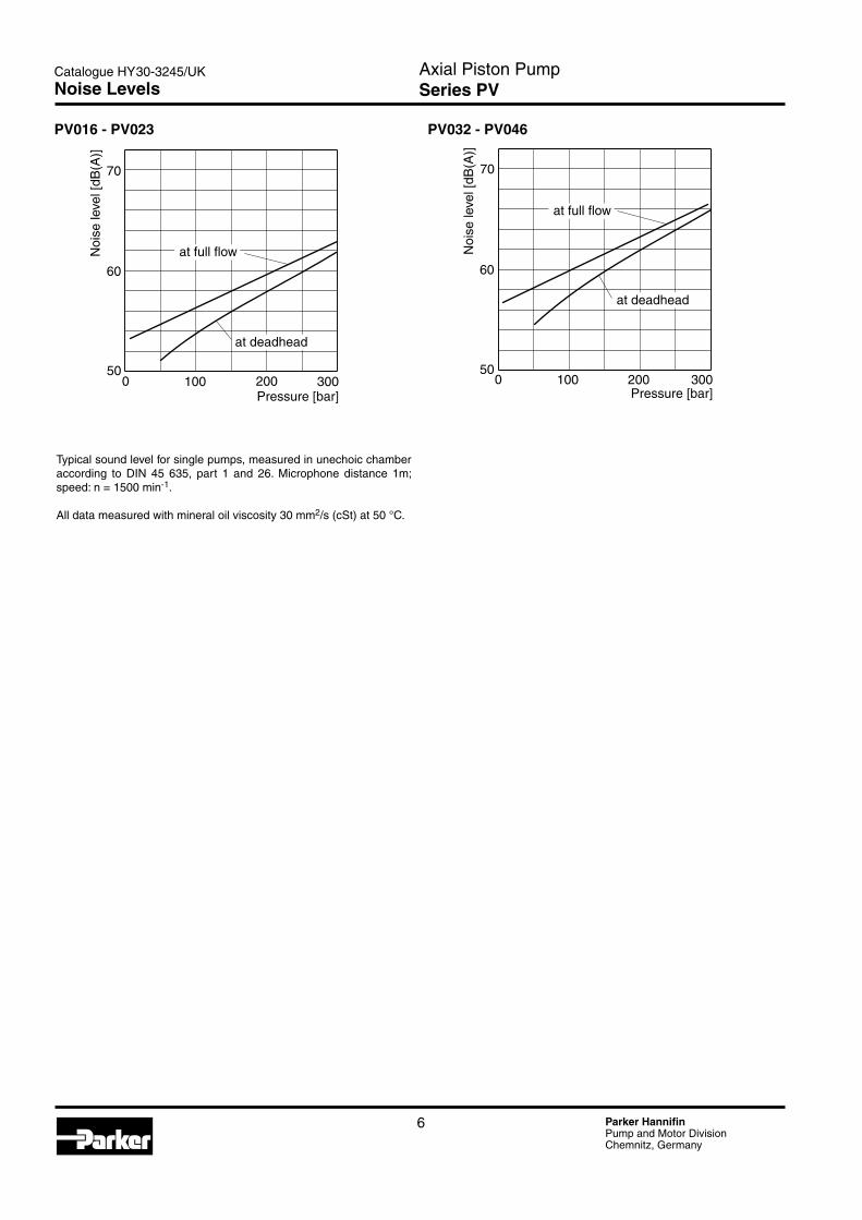
PV032 - PV046
Typical sound level for single pumps, measured in unechoic chamber according to DIN 45 635, part 1 and �6. Microphone distance 1m; speed: n = 1500 min-1.
All data measured with mineral oil viscosity 30 mm�/s (cSt) at 50 °C.
Noise Levels
PV016 - PV023

Axial Piston PumpSeries PV
7 Parker HannifinPump and Motor DivisionChemnitz, Germany
Catalogue HY30-3�45/UK
4
0
8
12
16
20
0 100 200 3000
20
40
60
80
100
0
5
10
15
20
25
Pressure [bar]E
ffici
ency
[%] (
over
all,
v olu
met
r ic)
Inpu
t pow
er [k
W]
Out
put f
low
[l/m
in]
vol. efficiency
overall e ncff eici y
output flow
input power at full flow
input power at deadhead
PV020
5
0
10
15
20
25
0 100 200 3000
20
40
60
80
100
0
6
12
18
24
30
Pressure [bar]
Effi
cien
cy [%
] (ov
eral
l, v o
lum
etric
)
Inpu
t pow
er [k
W]
Out
put f
low
[l/m
in]
overall nefficie cy
output flow, vol. efficiency
input power at full flow
input power at deadhead
PV023
5
0
10
15
20
25
0 100 200 3000
20
40
60
80
100
0
8
16
24
32
40
Pressure [bar]
Effi
cien
cy [%
] (ov
eral
l, v o
lum
etric
)
Inpu
t pow
er [k
W]
Out
put f
low
[l/m
in]
vol. efficiency
o everall effici ncyoutput flow
input
power
atful
l flow
input power at deadhead
Efficiency and case drain flows PV016, PV020, PV023The efficiency and power graphs are measured at an input speed of n = 1500 min-1, a temperature of 50 °C and a fluid viscosity of 30 mm�/s.
Case drain flow and compensator control flow leave via the drain port of the pump. To the values shown are to be added 1 to 1.� l/min , if at pilot operated compensa-tors the control flow of the pressure pilot valve also goes through the pump.
Please note: The values shown below are only valid for static operation. Under dynamic conditions and at rapid compensation of the pump the volume displaced by the servo piston also leaves the case drain port. This dynamic control flow can reach up to 40 l/min! Therefore the case drain line is to lead to the reservoir at full size and without restrictions as short and direct as possible.
Case drain flows PV016-023
Efficiency, power consumptionPV016
Efficiency and Case Drain Flows
Axial Piston PumpSeries PV
8 Parker HannifinPump and Motor DivisionChemnitz, Germany
Catalogue HY30-3�45/UK
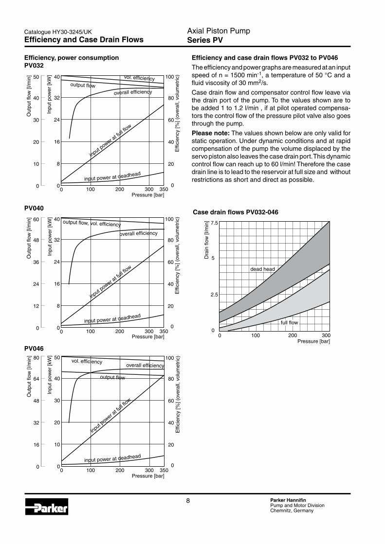
Efficiency and case drain flows PV032 to PV046The efficiency and power graphs are measured at an input speed of n = 1500 min-1, a temperature of 50 °C and a fluid viscosity of 30 mm�/s.
Case drain flow and compensator control flow leave via the drain port of the pump. To the values shown are to be added 1 to 1.� l/min , if at pilot operated compensa-tors the control flow of the pressure pilot valve also goes through the pump.
Please note: The values shown below are only valid for static operation. Under dynamic conditions and at rapid compensation of the pump the volume displaced by the servo piston also leaves the case drain port. This dynamic control flow can reach up to 60 l/min! Therefore the case drain line is to lead to the reservoir at full size and without restrictions as short and direct as possible.
Case drain flows PV032-046
Efficiency, power consumptionPV032
PV040
PV046
Efficiency and Case Drain Flows
Axial Piston PumpSeries PV
9 Parker HannifinPump and Motor DivisionChemnitz, Germany
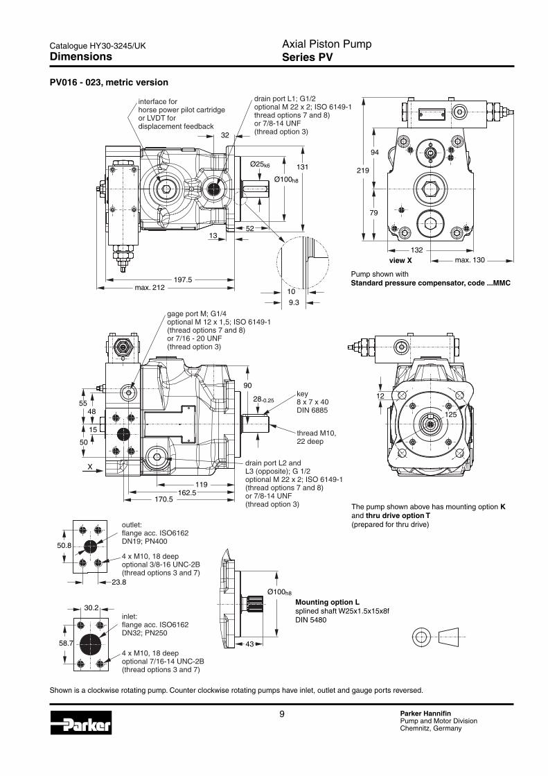
Catalogue HY30-3�45/UKDimensions
4 x M10, 18 deepoptional 7/16-14 UNC-2B(thread options 3 and 7)
shown here is rotation R (clockwise), with rotation L (counter-clockwise)inlet and outlet ports are on opposite side
outlet:flange acc. ISO6162DN19; PN400
inlet:flange acc. ISO6162DN32; PN250
4 x M10, 18 deepoptional 3/8-16 UNC-2B(thread options 3 and 7)
key8 x 7 x 40DIN 6885
thread M10,22 deep
drain port L2 andL3 (opposite); G 1/2optional M 22 x 2; ISO 6149-1(thread options 7 and 8)or 7/8-14 UNF(thread option 3)
drain port L1; G1/2optional M 22 x 2; ISO 6149-1thread options 7 and 8)or 7/8-14 UNF(thread option 3)
interface forhorse power pilot cartridgeor LVDT fordisplacement feedback
gage port M; G1/4optional M 12 x 1,5; ISO 6149-1(thread options 7 and 8)or 7/16 - 20 UNF(thread option 3)
197.5max. 212
1352
Ø25k6
Ø100h8
131
32
10
9.3
94
219
79
132max. 130view X
Pump shown withStandard pressure compensator, code ...MMC
The pump shown above has mounting option Kand thru drive option T(prepared for thru drive)
12
125
5548
15
50
X
119162.5
170.5
50.8
23.8
30.2
58.7 43
Mounting option Lsplined shaft W25x1.5x15x8fDIN 5480
Ø100h8
90
28-0.25
PV016 - 023, metric version
Shown is a clockwise rotating pump. Counter clockwise rotating pumps have inlet, outlet and gauge ports reversed.

Axial Piston PumpSeries PV
10 Parker HannifinPump and Motor DivisionChemnitz, Germany
Catalogue HY30-3�45/UK
A
HB
2747
224.5
197.5
G
E
DF
C
Thru drive:splined shaft13T-16/32 DP,flat root, side fit
Dimensions
Thru drive adaptors are available with the following dimensions
Drawing Dimension
Thru drive optionA B C D E F G Remark
Y 50,8 8 - - - 8� M8 SAE AA �-Bolt
A 8�,55 10 - - - 106 M10 SAE A �-Bolt
B 101,6 10,5 1�7 89,8 M1� - - SAE B 4-Bolt
G 63 8,5 85 60,1 M8 100 M8 �/4-Bolt
H 80 8,5 103 7�,8 M8 109 M10 �/4-Bolt
J 100 10,5 1�5 88,4 M10 - - 4-Bolt
Variation with thru drive

Axial Piston PumpSeries PV
11 Parker HannifinPump and Motor DivisionChemnitz, Germany
Catalogue HY30-3�45/UK
PV032 - 046, metric version
Shown is a clockwise rotating pump. Counter clockwise rotating pumps have inlet, outlet and gauge ports reversed.
Dimensions
68
10
9
16
227max 248
Ø125h8
Ø125h8
Ø32k6
149
36,5
138185
197
7160
50
57,2
69,9
27,8
35,7
35-0,25
99
160
14
112,5
97
255,5
160max 130
47
X
PVCMMCN Serie 45Code AM 350bar
interface for power pilot cartridge or LVDT for displacement feedback
drain port L1; G3/4optional M�7 x �; ISO 6149-1(thread options 7 and 8)or 1 1/16-1� UNF(thread option 3)
view X
Pump shown with standard pressure comp., code ...MMCgage port M; G1/4optional M1� x 1,5; ISO 6149-1(thread options 7 and 8)or 7/16 - �0 UNF(thread option 3)
drain ports L� and L3 (opposite); G3/4optopnal M�7 x �: ISO 6149-1(thread options 7 and 8)or 1 1/16 - 1� UNF(thread option 3)
thread M10,�� deep
key10 x 8 x 56DIN 6885
mounting optional Lsplined shaft W3�x1,5x�0x8fDIN 5480
Outlet:flange acc. ISO 616�DN�5; PN400
4 x M1�, �1 deepoptional 7/16-14 UNC-�B(thread options 3 and 7)
Inlet:flange acc. ISO 616�DN38; PN�00
4 x M1�, 18 deepoptional 1/�-13 UNC-�B(thread options 3 and 7)
mounting option K

Axial Piston PumpSeries PV
1� Parker HannifinPump and Motor DivisionChemnitz, Germany
Catalogue HY30-3�45/UK
Dimension H and available couplings see page 1�.At threads options 3 and 7 the dimensions E and G are UNC - �B threads.
Variation with thru drive
Dimensions
227
LL1
L2B
A
D
F
DF
E
G
G
Thru drive:splined shaftW�5x1,5x15x8fDIN 5480
Thru drive adaptors are available with the following dimensions
Drawing Dimension
Thru drive optionA B C D E F G Remark
A 8�,55 8 - - - 106 M10 SAE A �-Bolt
B 101,6 11 1�7 89,8 M1� 146 M1� SAE B �/4-Bolt
C 1�7 13,5 161,9 114,5 M1� - - SAE C 4-Bolt
G 63 8,5 85 60,1 M8 100 M8 �/4-Bolt
H 80 8,5 103 7�,8 M8 109 M10 �/4-Bolt
J 100 10,5 1�5 88,4 M10 140 M1� �/4-Bolt
K 1�5 10,5 160 113,1 M1� - - 4-Bolt

Axial Piston PumpSeries PV
13 Parker HannifinPump and Motor DivisionChemnitz, Germany
Catalogue HY30-3�45/UK
Code Second pump, SAE
T Prepared for thru drive option (plugged) Y SAE AA, diameter 50.8 mm A SAE A, diameter 8�.55 mm B SAE B, diameter 101.6 mm C SAE C, diameter 1�7,mm D SAE D, diameter 15�.4 mm E SAE E, diameter 165.1 mm
Second pump, metric
G Diameter 63 mm H Diameter 80 mm J Diameter 100 mm K Diameter 1�5 mm L Diameter 160 mm M Diameter �00 mm
Design series
(see name plate)
SealsSecond pump Thread
PVMK
Axial piston pump
series PV
BG
Size
Code Seals
N NBR V FPM E EPR
front pump second pump
metric,splined
keyed shaft,(only up to Ø 18,metric)
SAE,splined
30 84
69
91
85 87
92
Mounting kit
Code Thread
M Metric S SAE
PVMK
Axial piston pump
series PV
BG
SizeMounting kit
Coupling
Mounting kits for multiple pumps, for second pump option
Mounting kits for multiple pumps, couplings
Kit contains positions 30, 69, 84, 85 and 87, see drawing below.
Code Coupling for metric, splined shaft DIN 5480
01 N�5 x 1.5 x 15 0� N3� x 1.5 x �0 03 N40 x 1.5 x �5 04 N50 x � x �4 05 N60 x � x �8
Coupling for SAE splined shaft flat root, side fit
11 9T 16/3� 1� 11T 16/3� 13 13T 16/3� 14 15T 16/3� 15 14T 1�/�4 16 17T 1�/�4 17 13T 8/16 18 15T 8/16
Coupling + adaptor for keyed shaft
�0 Diameter 1� mm �1 Diameter 16 mm �� Diameter 18 mm
Kit contains positions 91 (and 9� for keyed shaft).
Design series
(see name plate)
K
Code Pump size
1 Pump size 1: PV016 - PV0�8 � Pump size �: PV03� - PV046, PV076 3 Pump size 3: PV063, PV080 - PV100 4 Pump size 4: PV140 - PV180 5 Pump size 5: PV�70
Code Pump size
1 Pump size 1: PV016 - PV0�8 � Pump size �: PV03� - PV046, PV076 3 Pump size 3: PV063, PV080 - PV100 4 Pump size 4: PV140 - PV180 5 Pump size 5: PV�70
Kits
Axial Piston PumpSeries PV
14 Parker HannifinPump and Motor DivisionChemnitz, Germany
Catalogue HY30-3�45/UK
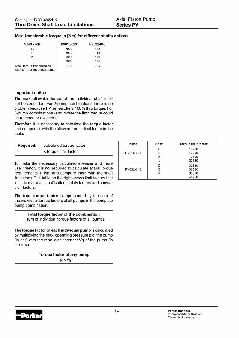
Pump Shaft Torque limit factor
D 17700 PV016-0�3 E 17700 K 17700 L �0130
D 3�680 PV03�-046 E 36380 K 33810 L 40�50
Shaft code PV016-023 PV032-046
D 300 550 E 300 610 K 300 570 L 405 675
Max. torque transmission 140 �75 cap. for rear mounted pump
Important noticeThe max. allowable torque of the individual shaft must not be exceeded. For �-pump combinations there is no problem because PV series offers 100% thru torque. For 3-pump combinations (and more) the limit torque could be reached or exceeded.
Therefore it is necessary to calculate the torque factor and compare it with the allowed torque limit factor in the table.
Required: calculated torque factor
< torque limit factor
To make the necessary calculations easier and more user friendly it is not required to calculate actual torque requirements in Nm and compare them with the shaft limitations. The table on the right shows limit factors that include material specification, safety factors and conver-sion factors.
Max. transferable torque in [Nm] for different shafts options
Total torque factor of the combination= sum of individual torque factors of all pumps
Torque factor of any pump = p x Vg
The total torque factor is represented by the sum of the individual torque factors of all pumps in the complete pump combination.
The torque factor of each individual pump is calculated by multiplying the max. operating pressure p of the pump (in bar) with the max. displacement Vg of the pump (in cm³/rev).
Thru Drive, Shaft Load Limitations

Axial Piston PumpSeries PV
15 Parker HannifinPump and Motor DivisionChemnitz, Germany
Catalogue HY30-3�45/UK
max. 17243.4
88.5
4641
24
45
49.5
P
T
A
Dimensions standard pressure compensator, code MMC
Dimensions remote pressure and load sensing compensator, code MR1 and MF1
max. 17243.4
88.5
41
24
45
69.5
P
P
T
T
A
Code “MM1“ has NG06/CETOP 3 interface topside as shown below.
Codes “MRC“ and “MFC“ have same dimensions, but no valve interface on top.
Dimensions power pilot cartridge
Compensator Dimensions
Axial Piston PumpSeries PV
16 Parker HannifinPump and Motor DivisionChemnitz, Germany
Catalogue HY30-3�45/UK
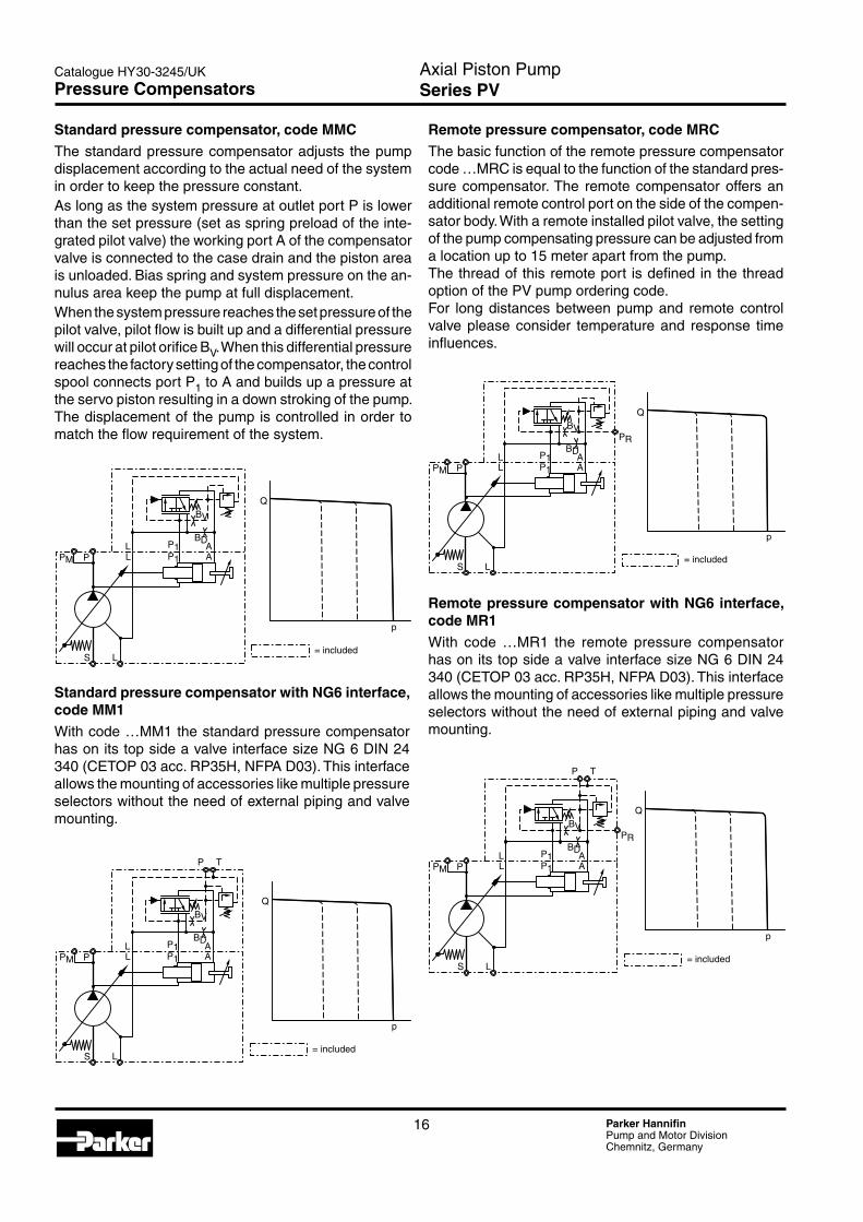
Standard pressure compensator, code MMCThe standard pressure compensator adjusts the pump displacement according to the actual need of the system in order to keep the pressure constant.As long as the system pressure at outlet port P is lower than the set pressure (set as spring preload of the inte-grated pilot valve) the working port A of the compensator valve is connected to the case drain and the piston area is unloaded. Bias spring and system pressure on the an-nulus area keep the pump at full displacement.When the system pressure reaches the set pressure of the pilot valve, pilot flow is built up and a differential pressure will occur at pilot orifice BV. When this differential pressure reaches the factory setting of the compensator, the control spool connects port P1 to A and builds up a pressure at the servo piston resulting in a down stroking of the pump. The displacement of the pump is controlled in order to match the flow requirement of the system.
Standard pressure compensator with NG6 interface, code MM1With code …MM1 the standard pressure compensator has on its top side a valve interface size NG 6 DIN �4 340 (CETOP 03 acc. RP35H, NFPA D03). This interface allows the mounting of accessories like multiple pressure selectors without the need of external piping and valve mounting.
Pressure Compensators
Remote pressure compensator with NG6 interface, code MR1With code …MR1 the remote pressure compensator has on its top side a valve interface size NG 6 DIN �4 340 (CETOP 03 acc. RP35H, NFPA D03). This interface allows the mounting of accessories like multiple pressure selectors without the need of external piping and valve mounting.
Remote pressure compensator, code MRCThe basic function of the remote pressure compensator code …MRC is equal to the function of the standard pres-sure compensator. The remote compensator offers an additional remote control port on the side of the compen-sator body. With a remote installed pilot valve, the setting of the pump compensating pressure can be adjusted from a location up to 15 meter apart from the pump.The thread of this remote port is defined in the thread option of the PV pump ordering code.For long distances between pump and remote control valve please consider temperature and response time influences.

Axial Piston PumpSeries PV
17 Parker HannifinPump and Motor DivisionChemnitz, Germany
Catalogue HY30-3�45/UK
Load sensing compensator code MFCThe pilot pressure of the load sensing compensator is taken from a load sensing port in the hydraulic system. This port is located downstream of a throttle valve (manu-ally or electronically operated). The pump compensator differential pressure is factory set to 10 bar.When the main stream throttle valve is set to a position, that creates the 10 bar pressure drop at a lower flow, than the pump nominal flow, the load sensing compensator will reduce the pump displacement accordingly to avoid power losses in the circuit. When the main stream throttle valve is closed, the pump will be compensated to stand-by operation at a pump outlet pressure of 10 bar.If the system pressure exceeds the setting of the inte-grated pilot valve, the pilot valve will create an additional pressure drop at the pilot orifice BV. This will lead to a pressure compensation of the pump in order not to exceed the set pressure.
Load sensing compensator NG6 interface, code MF1With code …MF1 the load sensing compensator has on its top side a valve interface size NG 6 DIN �4 340 (CETOP 03 acc. RP35H, NFPA D03). This interface allows the mounting of accessories like multiple pressure selectors without the need of external piping and valve mounting.
Pressure Compensators
Axial Piston PumpSeries PV
18 Parker HannifinPump and Motor DivisionChemnitz, Germany
Catalogue HY30-3�45/UKPower Compensators
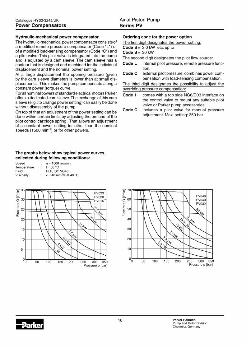
Hydraulic-mechanical power compensatorThe hydraulic-mechanical power compensator consists of a modified remote pressure compensator (Code *L*) or of a modified load-sensing compensator (Code *C*) and a pilot valve. This pilot valve is integrated into the pump and is adjusted by a cam sleeve. The cam sleeve has a contour that is designed and machined for the individual displacement and the nominal power setting.At a large displacement the opening pressure (given by the cam sleeve diameter) is lower than at small dis-placements. This makes the pump compensate along a constant power (torque) curve.For all nominal powers of standard electrical motors Parker offers a dedicated cam sleeve. The exchange of this cam sleeve (e. g.: to change power setting) can easily be done without disassembly of the pump.On top of that an adjustment of the power setting can be done within certain limits by adjusting the preload of the pilot control cartridge spring . That allows an adjustment of a constant power setting for other than the nominal speeds (1500 min-1) or for other powers.
Ordering code for the power optionThe first digit designates the power setting:Code B = 3.0 kW etc. up toCode S = 30 kW The second digit designates the pilot flow source:Code L internal pilot pressure, remote pressure func-
tion.Code C external pilot pressure, combines power com-
pensation with load-sensing compensation.The third digit designates the possibility to adjust the overriding pressure compensation:
Code 1 comes with a top side NG6/D03 interface on the control valve to mount any suitable pilot valve or Parker pump accessories.
Code C includes a pilot valve for manual pressure adjustment. Max. setting: 350 bar.
The graphs below show typical power curves, collected during following conditions:Speed : n = 1500 rev/minTemperature : t = 50 °CFluid : HLP, ISO VG46Viscosity : ν = 46 mm�/s at 40 °C
10
35
0
5
15
20
30
25
0 100 30050 150 250200 350
7.5 kW
PV023PV020PV016
Pressure p [bar]
Flo
w r
ate
Q [l
/min
]
18.5 kW
4 kW
5.5 kW
15 kW
3 kW
11 kW
20
70
0
10
30
40
60
50
0 100 30050 150 250200 350
PV046PV040PV032
Pressure p [bar]
Flo
w r
ate
Q [l
/min
]
5.5 kW
7.5 kW
11 kW
15 kW
22 kW
30 kW
18.5 kW

Axial Piston PumpSeries PV
19 Parker HannifinPump and Motor DivisionChemnitz, Germany
Catalogue HY30-3�45/UK
Power compensator code *LCThe control function of the power compensator is as described in the standard compensator section. The pump will start to compensate, when the pilot valve(s), integrated into compensator and pump, create a differential pressure of 15 bar at the pilot orifice BV. In addition to the standard pressure compensator the power option has an additional pilot valve in the pump housing. The pressure setting of this valve is controlled by a power feedback sleeve connected to the servo piston. At full displacement, the pressure setting is low and the pump will start to compensate at a lower pressure. The more the pump compensates, the more the feedback sleeve is moved by the down stroking servo piston. According to the contour of this sleeve, the pressure setting of the power pilot valve is raised. That gives a constant power requirement for the pump drive. At low pressures the pump can provide a high flow output, at high pressures the flow output has to be lowered, to avoid overloading of the drive motor. The contour of the power feedback sleeve is designed, to match the desired constant power curve (see following page). For each nominal setting a different contour sleeve is available. The last ordering code digit (*) defines the required setting (see ordering code pages).
Power compensator code *CCIn code …CC. the power compensator has an additional load sensing port. As for the load sensing compensator, code …FC the pilot pressure is not supplied internally, but from a load sensing port in the hydraulic system.Please note: in this case the load sensing pressure differential is set to 15 bar in order to meet the constant power curve, which is laid out for a 15 bar pilot pressure differential.With this feature the pump can be flow controlled by the main stream throttle valve, pressure controlled by the integrated pilot valve in the compensator and power controlled by the integrated pilot valve and contour sleeve in the pump housing.Both power compensator versions: code …LC* and code …CC* can be ordered also with the top side interface for accessories (codes …L1* resp. …C1*), with a built on directional control valve for electrical unloading (codes …LW* resp. …CW*) and with a built on proportional pilot valve for electronic setting of the max. compensating pressure (codes …LD* resp. …CD*).
Power Compensators
Axial Piston PumpSeries PV
�0 Parker HannifinPump and Motor DivisionChemnitz, Germany
Catalogue HY30-3�45/UK
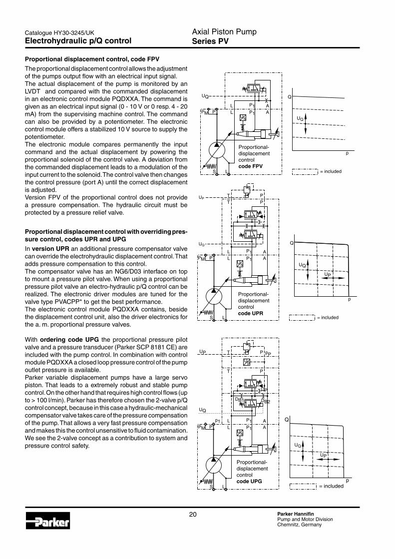
Proportional displacement control, code FPV
The proportional displacement control allows the adjustment of the pumps output flow with an electrical input signal.The actual displacement of the pump is monitored by an LVDT and compared with the commanded displacement in an electronic control module PQDXXA. The command is given as an electrical input signal (0 - 10 V or 0 resp. 4 - �0 mA) from the supervising machine control. The command can also be provided by a potentiometer. The electronic control module offers a stabilized 10 V source to supply the potentiometer.The electronic module compares permanently the input command and the actual displacement by powering the proportional solenoid of the control valve. A deviation from the commanded displacement leads to a modulation of the input current to the solenoid. The control valve then changes the control pressure (port A) until the correct displacement is adjusted.Version FPV of the proportional control does not provide a pressure compensation. The hydraulic circuit must be protected by a pressure relief valve.
Proportional displacement control with overriding pres-sure control, codes UPR and UPG
In version UPR an additional pressure compensator valve can override the electrohydraulic displacement control. That adds pressure compensation to this control.The compensator valve has an NG6/D03 interface on top to mount a pressure pilot valve. When using a proportional pressure pilot valve an electro-hydraulic p/Q control can be realized. The electronic driver modules are tuned for the valve type PVACPP* to get the best performance. The electronic control module PQDXXA contains, beside the displacement control unit, also the driver electronics for the a. m. proportional pressure valves.
With ordering code UPG the proportional pressure pilot valve and a pressure transducer (Parker SCP 8181 CE) are included with the pump control. In combination with control module PQDXXA a closed loop pressure control of the pump outlet pressure is available.Parker variable displacement pumps have a large servo piston. That leads to a extremely robust and stable pump control. On the other hand that requires high control flows (up to > 100 l/min). Parker has therefore chosen the �-valve p/Q control concept, because in this case a hydraulic-mechanical compensator valve takes care of the pressure compensation of the pump. That allows a very fast pressure compensation and makes this the control unsensitive to fluid contamination. We see the �-valve concept as a contribution to system and pressure control safety.
p
Q
UP
UQ
T P
P L
S L
AP1PMsU
L
T
A
P
P1
UP
UQ
= included
P L
S L
AP1PMs
p
U
U
L
T
A
P
P1
T P
DB1 DB2
DP
p1
pP
UP
UQ
UP
UQ
Q
p= included
P L
S L
AP1PMsU
L AP1
UQ
p
Q
UQ
= included
Proportional- displacementcontrolcode FPV
Proportional- displacementcontrolcode UPR
Proportional- displacementcontrolcode UPG
Electrohydraulic p/Q control

Axial Piston PumpSeries PV
�1 Parker HannifinPump and Motor DivisionChemnitz, Germany
Catalogue HY30-3�45/UK
The digital control module code PQDXXA-Z00 is designed for rail mounting.
Ordering code
OptionFor all frame sizes series PV
Digital control module for p/Q
control
Version A
Features• Digital control circuit• Parameter setting via RS-�3� interface• All settings (ramps, MIN/MAX, control parameters) can
be stored digitally and recalled from a PC to duplicate settings to other modules
• Ramp time up to 60 seconds• Compatible to the relevant european EMC specificati-
ons• Easy to use PC based setup software• Covers all displacements from 16 to �70 cm³/rev
• Covers all functions: displacement control, displace-ment control with open loop pressure control, displace-ment control with closed loop pressure control and displacement control with closed loop pressure control and electronic power limitation.
Technical data
Mounting style Snap-on mounting for EN500�� railBody material PolycarbonateInflammation class V�...V0 acc. UL 94Mounting position anyEnv. temperature range [°C] -�0...+55Protection class IP �0 acc. DIN 40 050Weight [g] 160Duty ratio [%] 100Supply voltage [V] 18...30VDC, ripple <5% eff.Rush in current [A] �� for 0.� msCurrent consumption [A] < 4 for p/Q control ; < � for Q-controlResolution [%] 0.0�5 (power 0.1)Interface RS�3�C, 9600 baud, 3.5 mm cinchEMC EN 50 081-�, EN 50 08�-�Connctors Screw terminals 0.�...�.5 mm², plug in styleCables [mm²] 1.5 (AWG 16) overall braid shield, for supply and solenoid connection 0.5 mm² (AWG �0) overall braid shield, for sensor and command signal connectionsMax. cable length [m] 50
PQD XX A
For programming the module via PC, an interface cable is needed, please order separately.
Please order the “interface cable to PC“
separately.Ordering code: PQDX-
XA-KABEL
Z00
Electronic Module PQDXXA (digital)
Axial Piston PumpSeries PV
�� Parker HannifinPump and Motor DivisionChemnitz, Germany
Catalogue HY30-3�45/UK
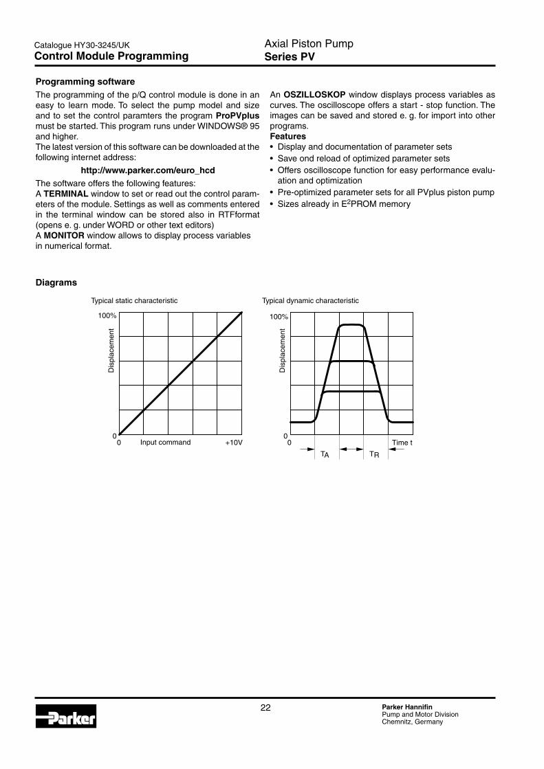
Programming softwareThe programming of the p/Q control module is done in an easy to learn mode. To select the pump model and size and to set the control paramters the program ProPVplus must be started. This program runs under WINDOWS® 95 and higher.The latest version of this software can be downloaded at the following internet address:
http://www.parker.com/euro_hcd
The software offers the following features:A TERMINAL window to set or read out the control param-eters of the module. Settings as well as comments entered in the terminal window can be stored also in RTFformat (opens e. g. under WORD or other text editors)A MONITOR window allows to display process variablesin numerical format.
Diagrams
An OSZILLOSKOP window displays process variables as curves. The oscilloscope offers a start - stop function. The images can be saved and stored e. g. for import into other programs.Features• Display and documentation of parameter sets• Save ond reload of optimized parameter sets• Offers oscilloscope function for easy performance evalu-
ation and optimization• Pre-optimized parameter sets for all PVplus piston pump• Sizes already in E�PROM memory
Control Module Programming

Axial Piston PumpSeries PV
�3 Parker HannifinPump and Motor DivisionChemnitz, Germany
Catalogue HY30-3�45/UK
Offer of SalePlease contact your Parker representation for a detailed ”Offer of Sale”.
FAILURE OR IMPROPER SELECTION OR IMPROPER USE OF THE PRODUCTS AND/OR SYSTEMS DESCRIBED HEREIN OR RELATED ITEMS CAN CAUSE DEATH, PERSONAL INJURY AND PROPERTY DAMAGE.
This document and other information from Parker Hannifin Corporation, its subsidiaries and authorized distributors provide product and/or system options for further investigation by users having technical expertise. It is important that you analyze all aspects of your application, including consequences of any failure, and review the information concerning the product or sys-tem in the current product catalogue. Due to the variety of operating conditions and applications for these products or systems, the user, through its own analysis and testing, is solely responsible for making the final selection of the products and systems and assuring that all performance, safety and warning requirements of the application are met.
The products described herein, including without limitation, product features, specifications, designs, availability and pricing, are subject to change by Parker Hannifin Corporation and its subsidiaries at any time without notice.
WARNING!
YOUR LOCAL REPRESENTATIVE 當地銷售及服務代理
SALES AND SERVICE LOCATIONSWORLDWIDE
FOR INFORMATION ABOUT SALES AND SERVICE LOCATIONS PLEASE CONTACT 產 品及服務聯繫資訊
http://www.kstci.com.tw/ [email protected] http://www.intracalzoni.com/ [email protected]
●柱塞泵 ●葉片泵 ●齒輪泵 ●柱塞馬達 ●擺線馬達 ●液壓密封件 ●電磁閥●比例閥●伺服閥 ●插式閥
●篩檢程式 ●蓄能器 ●液壓缸 ●伺服缸●動力單元 ●成套設備 ●液壓管件 ●液壓接頭 ●機電整合系統…
● Pumps & Motors ● Hydraulic Valves ● Hydraulic Seals ● Electrohydraulic Valves● DIN Cartridge Valves● Threaded Cartridge Valves ● Filtration/Fluid Analysis ● Accumulators ● Cylinders ● Power Units
● Compact Hydraulics ● Tube Fittings ● Rotary Actuators ● System Integrators...
Copyright @ KINGSTONE COMPONENT INC. 金聖泰實業 TEL:+886 2 8732-8566 FAX:+886 2 8732-8577