PV Grid Tie Inverter Solis 4G Single Phase Inverter3.3 Keypad 3.4 LCD 4. Installation ... The...
24
2016, Ningbo Ginlong Technologies Co., Ltd. C PV Grid Tie Inverter Installation and Operation Manual Solis 4G Single Phase Inverter Ver 1.1 Solis-1P1K-4G, Solis-1P1.5K-4G, Solis-1P2K-4G, Solis-1P2.5K4-4G, Solis-1P3K-4G, Solis-1P3.6K-4G, Solis-1P4K-4G, Solis-1P4.6K-4G,Solis-1P5K-4G Ningbo Ginlong Technologies Co., Ltd. No. 57 Jintong Road, Binhai Industrial Park, Xiangshan, Ningbo, Zhejiang, 315712, P.R.China. Tel: +86 (0)574 6578 1806 Fax: +86 (0)574 6578 1606 If you encounter any problem on the inverter, please find out the inverter S/N and contact us, we will try to respond to your question ASAP.
Transcript of PV Grid Tie Inverter Solis 4G Single Phase Inverter3.3 Keypad 3.4 LCD 4. Installation ... The...
2016, Ningbo Ginlong Technologies Co., Ltd.C
PV Grid Tie Inverter
Installation and Operation Manual
Solis 4G Single Phase Inverter
Ver 1.1
Solis-1P1K-4G, Solis-1P1.5K-4G, Solis-1P2K-4G, Solis-1P2.5K4-4G, Solis-1P3K-4G, Solis-1P3.6K-4G, Solis-1P4K-4G, Solis-1P4.6K-4G,Solis-1P5K-4G
Ningbo Ginlong Technologies Co., Ltd.
No. 57 Jintong Road, Binhai Industrial Park, Xiangshan, Ningbo,
Zhejiang, 315712, P.R.China.
Tel: +86 (0)574 6578 1806
Fax: +86 (0)574 6578 1606
If you encounter any problem on the inverter, please find out the inverter S/N
and contact us, we will try to respond to your question ASAP.
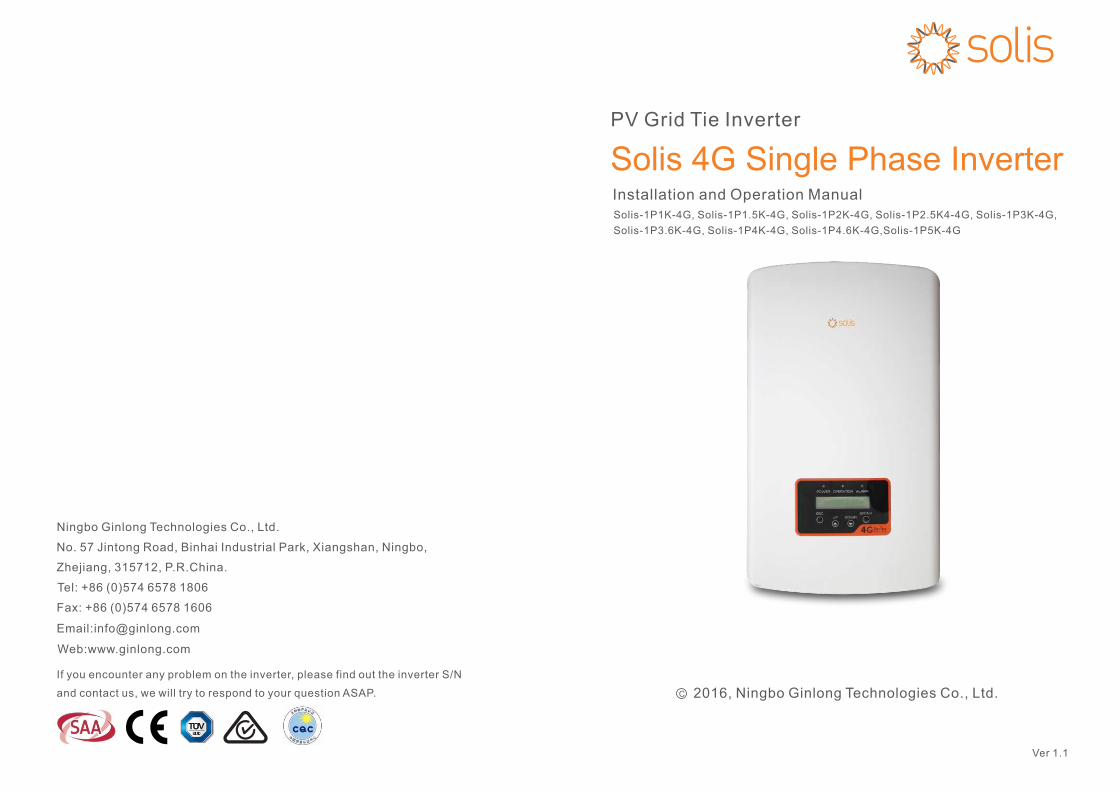
1. Introduction
2. Safety Instructions 2.1 Safety Symbols2.2 General Safety Instructions
2.3 Notice For Use3. Overview
3.1 Front Panel Display3.2 LED Status Indicator Lights3.3 Keypad
3.4 LCD4. Installation
4.1 Select Location for the Inverter4.2 Mounting the Inverter
4.3 Electrical Connections
Contents
.1.
3
555677788991113
………………………
………………………………………
………………………………………………
………………………………
………………………
……………………………………………
…………………………………………………
………………………………………………
…………………
…………………………………
……………………………
6. Operation 24………………………………………………
5. Start & Stop
5.1 Start the Inverter5.2 Stop the Inverter
232323
………………………………………
………………………………
…………………………………
………………………………………………
……………………………………
………………………………………
1.1 Product Description 3…………………………………
1.2 Packaging 4…………………………………………
4.3.1 Connect PV side of inverter 13………………
4.3.2 Connect grid side of inverter 16………………
4.3.3 External ground connection 18………………
4.3.4 Max. overcurrent protection device (OCPD) 19…
4.3.5 Inverter monitoring connection 19……………
4.3.8 DRED port connections4.3.7 CT connections 21……………………………
21…………………
4.3.6 Electrical connection diagram 20…………
1. Introduction
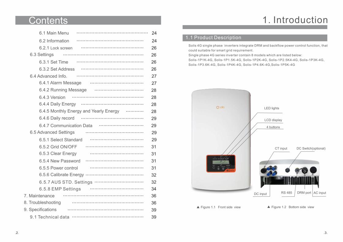
1.1 Product Description
Figure 1.1 Front side view
.3.
Solis 4G single phase inverters integrate DRM and backflow power control function, thatcould suitable for smart grid requirement.Single phase 4G series inverter contain 8 models which are listed below:Solis-1P1K-4G, Solis-1P1.5K-4G, Solis-1P2K-4G, Solis-1P2.5K4-4G, Solis-1P3K-4G, Solis-1P3.6K-4G, Solis-1P4K-4G, Solis-1P4.6K-4G,Solis-1P5K-4G
Figure 1.2 Bottom side view
DC Switch(optional)
DC input AC inputRS 485
LCD display
4 buttons
LED lights
6.3 Settings
6.3.1 Set Time6.3.2 Set Address
6.4 Advanced Info.6.4.1 Alarm Message
Contents
.2.
2626262727
………………………………………………
………………………………………
……………………………………
………………………………………
………………………………
6.4.3 Version6.4.4 Daily Energy6.4.5 Monthly Energy and Yearly Energy
6.5 Advanced Settings
6.5.1 Select Standard6.5.2 Grid ON/OFF
7. Maintenance8. Troubleshooting9. Specifications
282828
292931
363639
…………………………………………
……………………………………
…………
…………………………………
………………………………
…………………………………
………………………………………………
…………………………………………
……………………………………………
6.4.2 Running Message 28……………………………
32……………………………
6.5.3 Clear Energy
6.5.4 New Password3131
………………………………
…………………………………
6.2.1 Lock screen 26……………………………………
9.1 Technical data 39…………………………………………
6.4.6 Daily record
6.4.7 Communication Data2929
……………………………………
…………………………
6.5.5 Power control6.5.6 Calibrate Energy
3132
………………………………
…………………………………
6.2 Information 24………………………………………
CT input
DRM port
6.1 Main Menu 24…………………………………………
6.5.7 AUS STD. Settings34………………………………6.5.8 EMP Settings
2.Safety Instructions
2.2 General Safety Instructions
WARNING: Electrical installations must be done in accordance with the local and national electrical safety standards.
.5.
CAUTION: CAUTION, RISK OF ELECTRIC SHOCK symbol indicates important safety instructions, which if not correctly followed, could result in electric shock.
CAUTION: CAUTION, HOT SURFACE symbol indicates safety instructions, which if not correctly followed, could result in burns.
NOTE: NOTE symbol indicates important safety instructions, which if not correctly followed, could result in some damage or the destruction of the inverter.
2.1 Safety Symbols
Safety symbols used in this manual, which highlight potential safety risks and important
safety information, are listed as follows:
WARNING: WARNING symbol indicates important safety instructions, which if not correctly followed, could result in serious injury or death.
Improper use may result in potential electric shock hazards or burns. This manual
contains important instructions that should be followed during installation and
maintenance. Please read these instructions carefully before use and keep them for
future reference.
WARNING:Please don’t connect PV array positive(+) or negative(-) to ground, it could
cause serious damage to the inverter.
1. Introduction
.4.
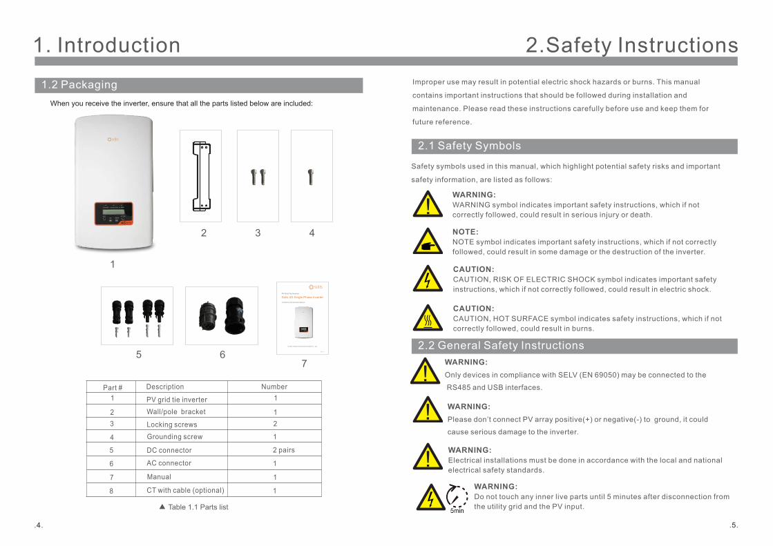
1.2 Packaging
Part #1
Description
PV grid tie inverter
2 Wall/pole bracket 3 Locking screws
4
1
7
32 4
5
Number1
12
2 pairs
When you receive the inverter, ensure that all the parts listed below are included:
Table 1.1 Parts list
Grounding screw 1
2016, Ningbo Ginlong Technologies Co., Ltd.C
PV Grid Tie Inverter
Installation and Operation Manual
Solis 4G Single Phase Inverter
Ver 1.05
AC connector6 1
6
Manual7 1
DC connector
CT with cable (optional)8 1
WARNING:Only devices in compliance with SELV (EN 69050) may be connected to the
RS485 and USB interfaces.
WARNING: Do not touch any inner live parts until 5 minutes after disconnection fromthe utility grid and the PV input.
3. Overview
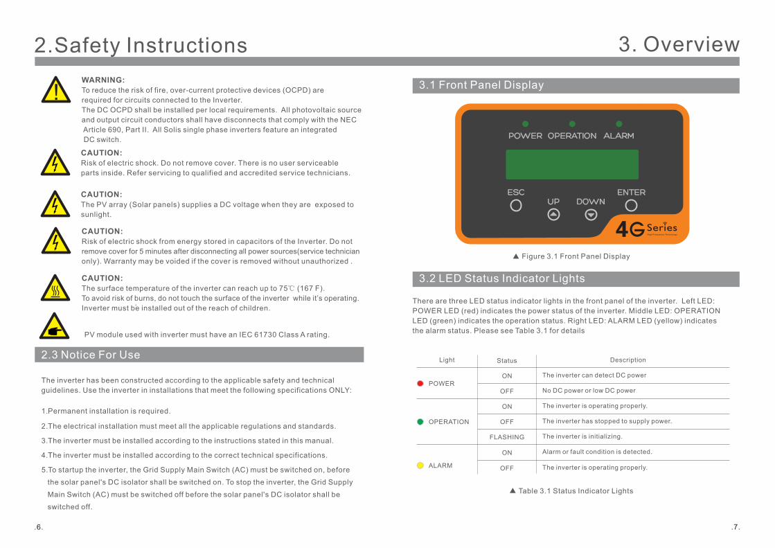
3.1 Front Panel Display
Figure 3.1 Front Panel Display
3.2 LED Status Indicator Lights
There are three LED status indicator lights in the front panel of the inverter. Left LED: POWER LED (red) indicates the power status of the inverter. Middle LED: OPERATIONLED (green) indicates the operation status. Right LED: ALARM LED (yellow) indicates the alarm status. Please see Table 3.1 for details
Description
The inverter can detect DC power
No DC power or low DC power
The inverter is operating properly.
The inverter has stopped to supply power.
The inverter is initializing.
Alarm or fault condition is detected.
The inverter is operating properly.
Status
ON
OFF
ON
OFF
OFF
ON
FLASHING
Light
POWER
OPERATION
ALARM
Table 3.1 Status Indicator Lights
.7.
2.Safety Instructions
2.3 Notice For Use
The inverter has been constructed according to the applicable safety and technical guidelines. Use the inverter in installations that meet the following specifications ONLY:
1. Permanent installation is required.
2. The electrical installation must meet all the applicable regulations and standards.
3. The inverter must be installed according to the instructions stated in this manual.
4. The inverter must be installed according to the correct technical specifications.
5. To startup the inverter, the Grid Supply Main Switch (AC) must be switched on, before
the solar panel's DC isolator shall be switched on. To stop the inverter, the Grid Supply
Main Switch (AC) must be switched off before the solar panel's DC isolator shall be
switched off.
.6.
CAUTION: The PV array (Solar panels) supplies a DC voltage when they are exposed to sunlight.
CAUTION: Risk of electric shock from energy stored in capacitors of the Inverter. Do not remove cover for 5 minutes after disconnecting all power sources(service technicianonly). Warranty may be voided if the cover is removed without unauthorized .
CAUTION: The surface temperature of the inverter can reach up to 75℃ (167 F).To avoid risk of burns, do not touch the surface of the inverter while it’s operating. Inverter must be installed out of the reach of children.
WARNING: To reduce the risk of fire, over-current protective devices (OCPD) are required for circuits connected to the Inverter. The DC OCPD shall be installed per local requirements. All photovoltaic source and output circuit conductors shall have disconnects that comply with the NEC Article 690, Part II. All Solis single phase inverters feature an integrated DC switch.
CAUTION: Risk of electric shock. Do not remove cover. There is no user serviceable parts inside. Refer servicing to qualified and accredited service technicians.
PV module used with inverter must have an IEC 61730 Class A rating.
4. Installation
4.1 Select a Location for the Inverter
.9.
3.3 Keypad
3.4 LCD
There are four keys in the front panel of the Inverter(from left to right):
ESC, UP, DOWN and ENTER keys. The keypad is used for:
Scrolling through the displayed options (the UP and DOWN keys);
Access to modify the adjustable settings (the ESC and ENTER keys).
3. Overview
The two-line Liquid Crystal Display (LCD) is located on the front panel of the Inverter,
which shows the following information:
Inverter operation status and data;
Service messages for operator;
Alarm messages and fault indications.
.8.
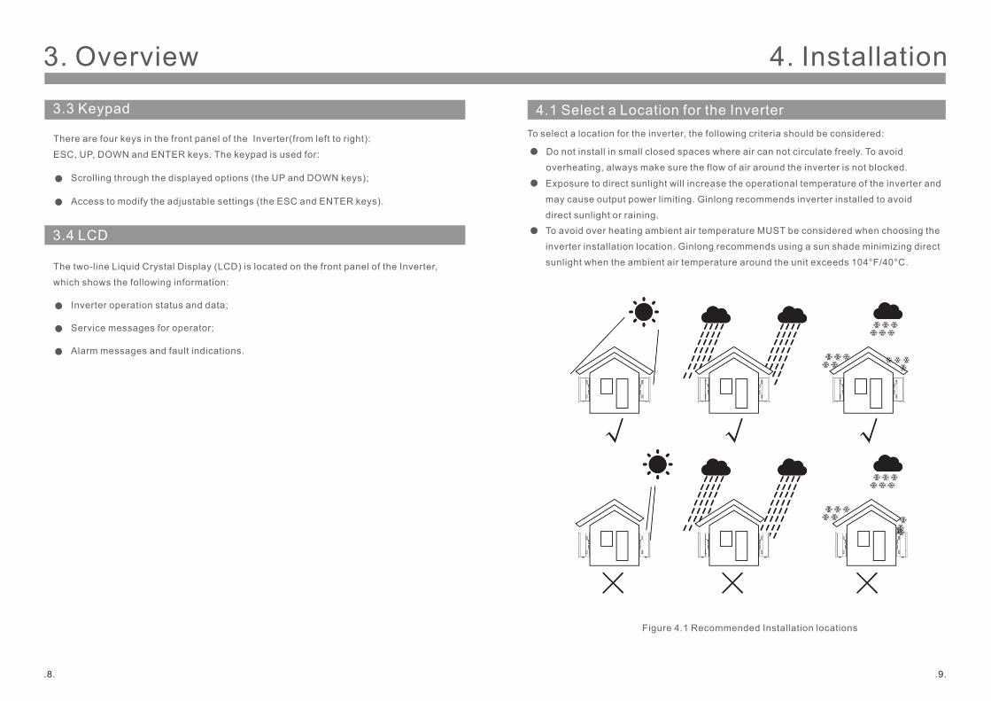
To select a location for the inverter, the following criteria should be considered:
To avoid over heating ambient air temperature MUST be considered when choosing the
inverter installation location. Ginlong recommends using a sun shade minimizing direct
sunlight when the ambient air temperature around the unit exceeds 104°F/40°C.
Do not install in small closed spaces where air can not circulate freely. To avoid
overheating, always make sure the flow of air around the inverter is not blocked.
Exposure to direct sunlight will increase the operational temperature of the inverter and
may cause output power limiting. Ginlong recommends inverter installed to avoid
direct sunlight or raining.
Figure 4.1 Recommended Installation locations
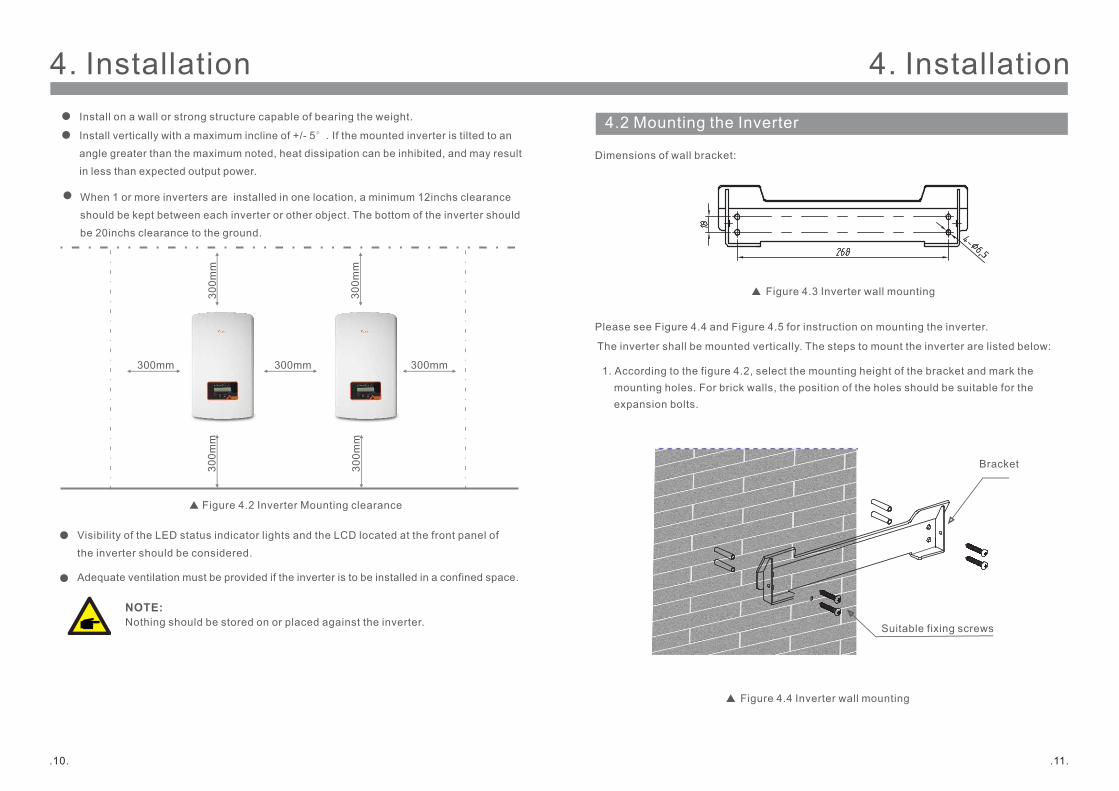
When 1 or more inverters are installed in one location, a minimum 12inchs clearance
should be kept between each inverter or other object. The bottom of the inverter should
be 20inchs clearance to the ground.
Visibility of the LED status indicator lights and the LCD located at the front panel of
the inverter should be considered.
Adequate ventilation must be provided if the inverter is to be installed in a confined space.
NOTE: Nothing should be stored on or placed against the inverter.
300mm
300m
m
300m
m300mm 300mm
300m
m
300m
m
Figure 4.2 Inverter Mounting clearance
Install on a wall or strong structure capable of bearing the weight.
Install vertically with a maximum incline of +/- 5°.If the mounted inverter is tilted to an
angle greater than the maximum noted, heat dissipation can be inhibited, and may result
in less than expected output power.
4. Installation4. Installation
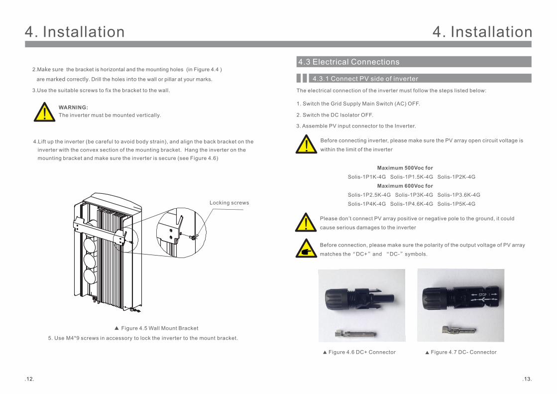
Dimensions of wall bracket:
Please see Figure 4.4 and Figure 4.5 for instruction on mounting the inverter.
Figure 4.3 Inverter wall mounting
.10. .11.
4.2 Mounting the Inverter
The inverter shall be mounted vertically. The steps to mount the inverter are listed below:
Suitable fixing screws
Bracket
1. According to the figure 4.2, select the mounting height of the bracket and mark the mounting holes. For brick walls, the position of the holes should be suitable for the expansion bolts.
Figure 4.4 Inverter wall mounting
.13.
4. Installation4. Installation
.12.
WARNING:The inverter must be mounted vertically.
4. Lift up the inverter (be careful to avoid body strain), and align the back bracket on the inverter with the convex section of the mounting bracket. Hang the inverter on the mounting bracket and make sure the inverter is secure (see Figure 4.6)
4.3 Electrical Connections
4.3.1 Connect PV side of inverter
The electrical connection of the inverter must follow the steps listed below:
1. Switch the Grid Supply Main Switch (AC) OFF.
2. Switch the DC Isolator OFF.
3. Assemble PV input connector to the Inverter.
Before connecting inverter, please make sure the PV array open circuit voltage is
within the limit of the inverter
2.Make sure the bracket is horizontal and the mounting holes (in Figure 4.4 )
are marked correctly. Drill the holes into the wall or pillar at your marks.
3. Use the suitable screws to fix the bracket to the wall.
Figure 4.5 Wall Mount Bracket
5. Use M4*9 screws in accessory to lock the inverter to the mount bracket.
Locking screws
Before connection, please make sure the polarity of the output voltage of PV array
matches the“DC+”and “DC-”symbols.
Maximum 500Voc forSolis-1P1K-4G Solis-1P1.5K-4G Solis-1P2K-4G
Maximum 600Voc forSolis-1P2.5K-4G Solis-1P3K-4G Solis-1P3.6K-4G
Solis-1P4K-4G Solis-1P4.6K-4G Solis-1P5K-4G
Please don’t connect PV array positive or negative pole to the ground, it could
cause serious damages to the inverter
Figure 4.6 DC+ Connector Figure 4.7 DC- Connector
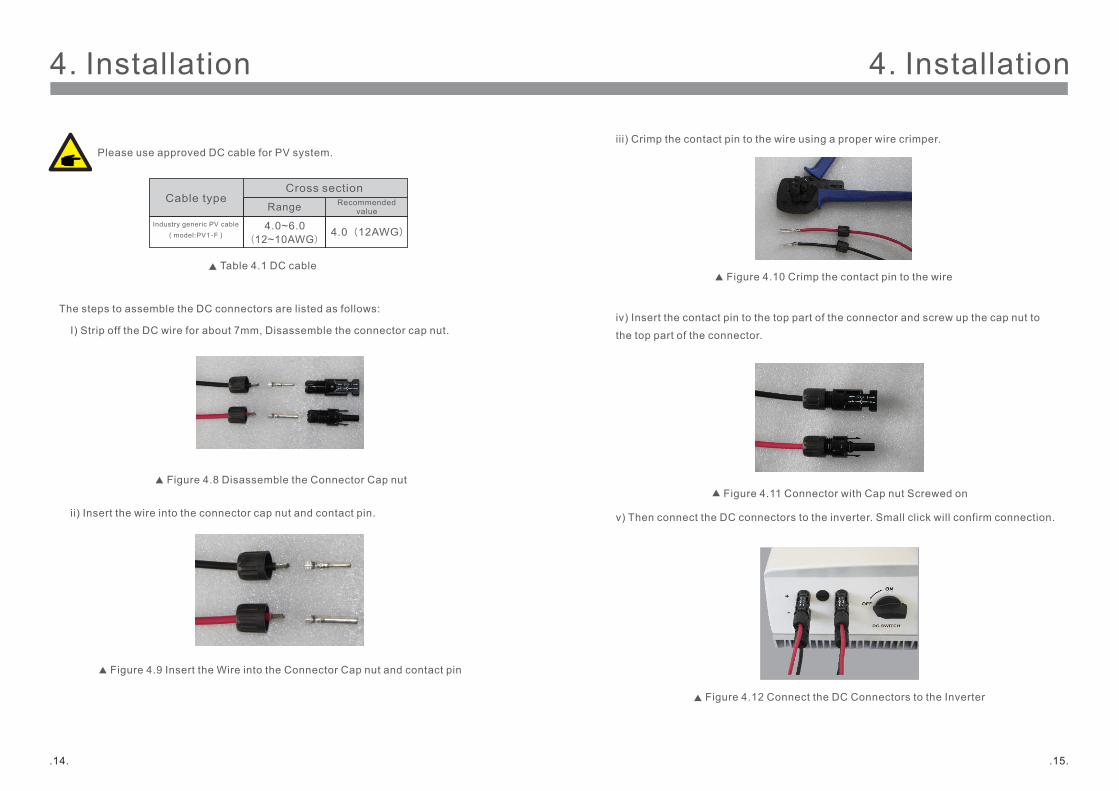
iii) Crimp the contact pin to the wire using a proper wire crimper.
Figure 4.10 Crimp the contact pin to the wire
iv) Insert the contact pin to the top part of the connector and screw up the cap nut to
the top part of the connector.
4. Installation
The steps to assemble the DC connectors are listed as follows:
I) Strip off the DC wire for about 7mm, Disassemble the connector cap nut.
ii) Insert the wire into the connector cap nut and contact pin.
Figure 4.8 Disassemble the Connector Cap nut
Figure 4.9 Insert the Wire into the Connector Cap nut and contact pin
4. Installation
.15..14.
Please use approved DC cable for PV system.
Cable type
4.0~6.0
Cross section
RangeIndustry generic PV cable
(model:PV1-F)
Recommended value
4.0(12AWG)(12~10AWG)
Table 4.1 DC cable
Figure 4.11 Connector with Cap nut Screwed on
Figure 4.12 Connect the DC Connectors to the Inverter
v) Then connect the DC connectors to the inverter. Small click will confirm connection.
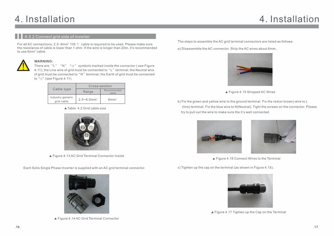
Figure 4.14 AC Grid Terminal Connector
Figure 4.13 AC Grid Terminal Connector Inside
The steps to assemble the AC grid terminal connectors are listed as follows:
a) Disassemble the AC connector. Strip the AC wires about 6mm,
Figure 4.15 Stripped AC Wires
4. Installation
Each Solis Single Phase Inverter is supplied with an AC grid terminal connector.
There are symbols marked inside the connector ( see Figure4.11), the Line wire of grid must be connected to“L”terminal; the Neutral wireof grid must be connected to“N”terminal; the Earth of grid must be connectedto“ ”(see Figure 4.11).
For all AC connections, 2.5- 6mm 105 ℃ cable is required to be used. Please make sure 2
the resistance of cable is lower than 1 ohm. If the wire is longer than 20m, it's recommended to use 6mm cable.2
WARNING:
4. Installation
Cable type
2.5~6.0mm²
Cross section
Range
Industry generic grid cable
Recommended value
6mm²
Table 4.2 Grid cable size
4.3.2 Connect grid side of inverter
.17..16.
c) Tighten up the cap on the terminal (as shown in Figure 4.15).
Figure 4.17 Tighten up the Cap on the Terminal
b) Fix the green and yellow wire to the ground terminal. Fix the red(or brown) wire to L
(line) terminal. Fix the blue wire to N(Neutral). Tight the screws on the connector. Please
try to pull out the wire to make sure the it’s well connected.
Figure 4.16 Connect Wires to the Terminal
4. Installation
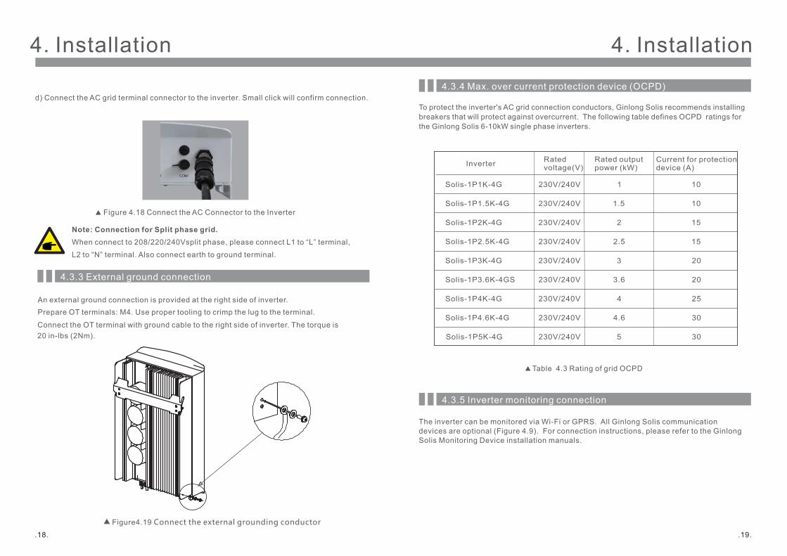
d) Connect the AC grid terminal connector to the inverter. Small click will confirm connection.
Figure 4.18 Connect the AC Connector to the Inverter
4. Installation
Note: Connection for Split phase grid.When connect to 208/220/240Vsplit phase, please connect L1 to “L” terminal,
L2 to “N” terminal. Also connect earth to ground terminal.
4.3.3 External ground connection
An external ground connection is provided at the right side of inverter. Prepare OT terminals: M4. Use proper tooling to crimp the lug to the terminal. Connect the OT terminal with ground cable to the right side of inverter. The torque is 20 in-lbs (2Nm).
Figure4.19 Connect the external grounding conductor
.19..18.
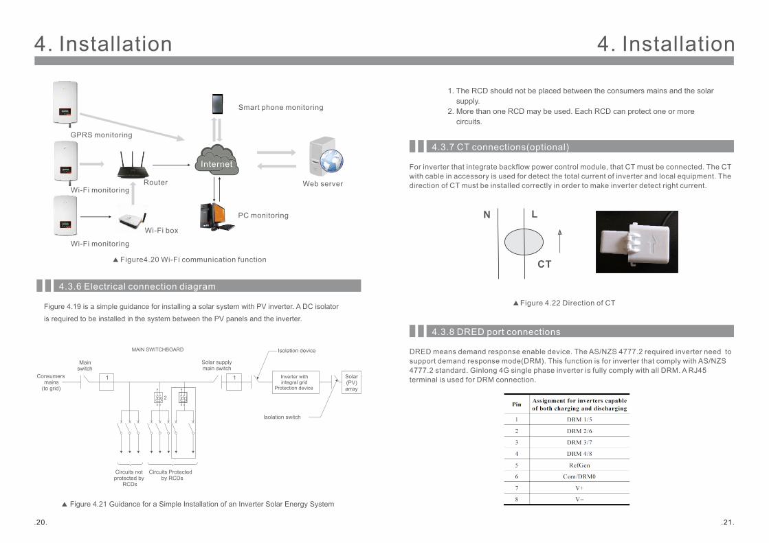
The inverter can be monitored via Wi-Fi or GPRS. All Ginlong Solis communicationdevices are optional (Figure 4.9). For connection instructions, please refer to the GinlongSolis Monitoring Device installation manuals.
To protect the inverter's AC grid connection conductors, Ginlong Solis recommends installing breakers that will protect against overcurrent. The following table defines OCPD ratings for the Ginlong Solis 6-10kW single phase inverters.
Inverter
Solis-1P1K-4G
Rated voltage(V)
230V/240V
Rated output power (kW)
Current for protection device (A)
1
1.5
2
2.5
3.6
4
10
3
Solis-1P4K-4G
Solis-1P3.6K-4GS
Solis-1P3K-4G
Solis-1P2.5K-4G
Solis-1P2K-4G
Solis-1P1.5K-4G
4.6Solis-1P4.6K-4G 30
25
20
20
15
15
10
4.3.4 Max. over current protection device (OCPD)
Table 4.3 Rating of grid OCPD
5Solis-1P5K-4G 30
230V/240V
230V/240V
230V/240V
230V/240V
230V/240V
230V/240V
230V/240V
230V/240V
4.3.5 Inverter monitoring connection
4. Installation4. Installation
Figure4.20 Wi-Fi communication function
Internet
GPRS monitoring
Wi-Fi monitoring
Smart phone monitoring
PC monitoring
Web serverRouter
Wi-Fi monitoring
Wi-Fi box
4.3.6 Electrical connection diagram
.21..20.
Figure 4.19 is a simple guidance for installing a solar system with PV inverter. A DC isolator
is required to be installed in the system between the PV panels and the inverter.
Figure 4.21 Guidance for a Simple Installation of an Inverter Solar Energy System
Isolation switch
Solar supply main switch
Consumersmains
(to grid)
Mainswitch
MAIN SWITCHBOARD
Circuits notprotected by
RCDs
Circuits Protectedby RCDs
Isolation device
Inverter withintegral grid
Protection device
Solar(PV)array
11
2
1. The RCD should not be placed between the consumers mains and the solar supply.2. More than one RCD may be used. Each RCD can protect one or more circuits.
4.3.7 CT connections(optional)
For inverter that integrate backflow power control module, that CT must be connected. The CT with cable in accessory is used for detect the total current of inverter and local equipment. The direction of CT must be installed correctly in order to make inverter detect right current.
N L
CT
Figure 4.22 Direction of CT
4.3.8 DRED port connections
DRED means demand response enable device. The AS/NZS 4777.2 required inverter need to support demand response mode(DRM). This function is for inverter that comply with AS/NZS4777.2 standard. Ginlong 4G single phase inverter is fully comply with all DRM. A RJ45 terminal is used for DRM connection.
4. InstallationNOTE: Ginlong 4G inverter is designed to provide 12V power for DRED.
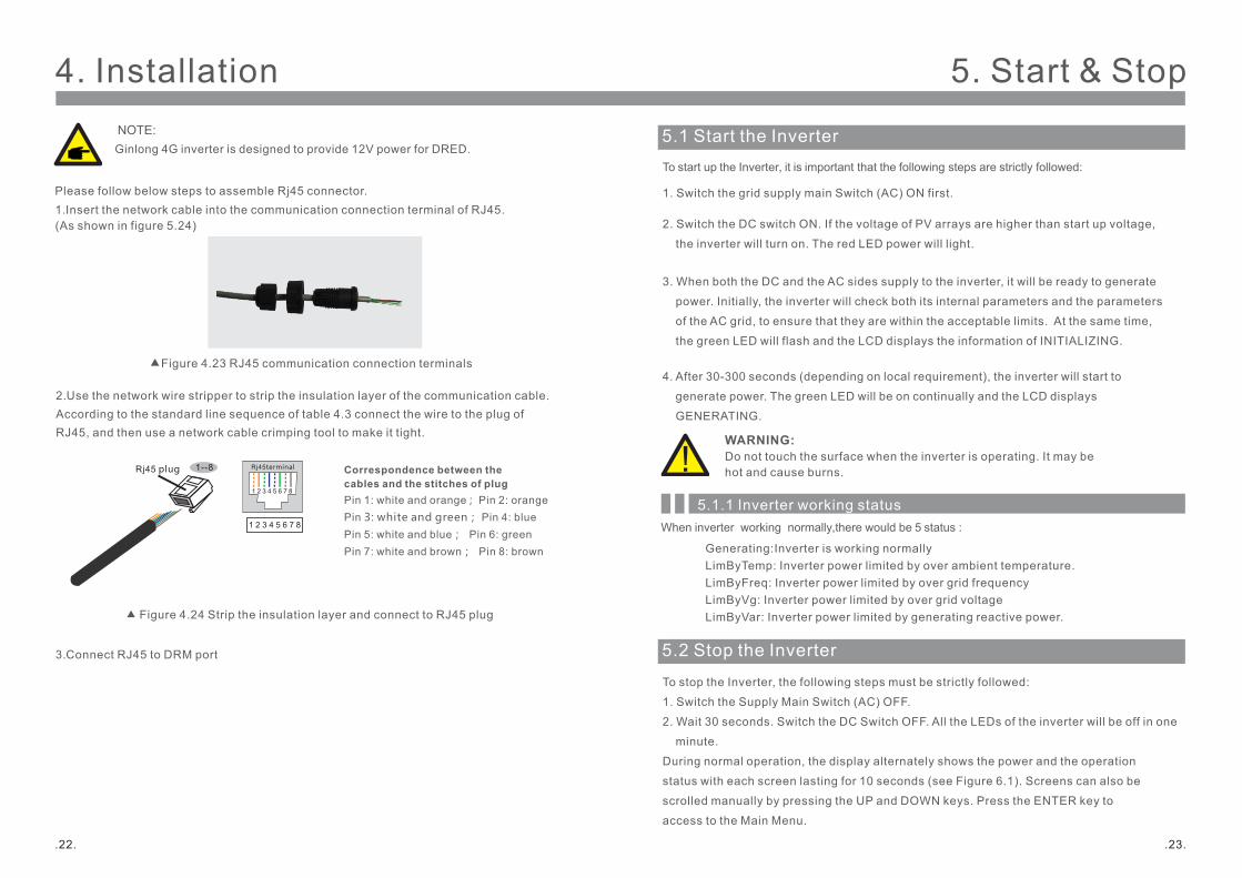
Please follow below steps to assemble Rj45 connector. 1. Insert the network cable into the communication connection terminal of RJ45. (As shown in figure 5.24)
Figure 4.23 RJ45 communication connection terminals
2. Use the network wire stripper to strip the insulation layer of the communication cable. According to the standard line sequence of table 4.3 connect the wire to the plug of RJ45, and then use a network cable crimping tool to make it tight.
3. Connect RJ45 to DRM port
Figure 4.24 Strip the insulation layer and connect to RJ45 plug
Correspondence between the cables and the stitches of plugPin 1: white and orange ; Pin 2: orangePin 3: white and green; Pin 4: bluePin 5: white and blue; Pin 6: greenPin 7: white and brown; Pin 8: brown
1--8Rj45 plug Rj45terminal
1 2 3 4 5 6 7 8
1 2 3 4 5 6 7 8
.23..22.
5.1 Start the InverterTo start up the Inverter, it is important that the following steps are strictly followed:
1. Switch the grid supply main Switch (AC) ON first.
2. Switch the DC switch ON. If the voltage of PV arrays are higher than start up voltage,
the inverter will turn on. The red LED power will light.
3. When both the DC and the AC sides supply to the inverter, it will be ready to generate
power. Initially, the inverter will check both its internal parameters and the parameters
of the AC grid, to ensure that they are within the acceptable limits. At the same time,
the green LED will flash and the LCD displays the information of INITIALIZING.
4. After 30-300 seconds (depending on local requirement), the inverter will start to
generate power. The green LED will be on continually and the LCD displays
GENERATING.
WARNING: Do not touch the surface when the inverter is operating. It may be hot and cause burns.
5.2 Stop the Inverter
To stop the Inverter, the following steps must be strictly followed:
1. Switch the Supply Main Switch (AC) OFF.
2. Wait 30 seconds. Switch the DC Switch OFF. All the LEDs of the inverter will be off in one
minute.
During normal operation, the display alternately shows the power and the operation
status with each screen lasting for 10 seconds (see Figure 6.1). Screens can also be
scrolled manually by pressing the UP and DOWN keys. Press the ENTER key to
access to the Main Menu.
5. Start & Stop
5.1.1 Inverter working status
Generating:Inverter is working normallyLimByTemp: Inverter power limited by over ambient temperature.LimByFreq: Inverter power limited by over grid frequencyLimByVg: Inverter power limited by over grid voltageLimByVar: Inverter power limited by generating reactive power.
When inverter working normally,there would be 5 status :
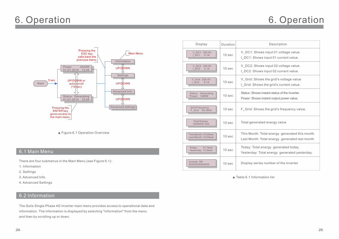
6.1 Main Menu
Figure 6.1 Operation Overview
5 secStart
Power 3424W01-01-2014 12:04
Status: Generating01-01-2014 12:04
Information
Settings
Advanced Info.
Advanced settings
UP/DOWN
UP/DOWN
UP/DOWN
UP/DOWN orauto-scroll
(10 sec)
Pressing theENTER key
gives access tothe main menu.
Pressing theESC key
calls back theprevious menu.
Main Menu
There are four submenus in the Main Menu (see Figure 6.1):
1. Information
2. Settings
3. Advanced Info.
4. Advanced Settings
6.2 Information
The Solis Single Phase 4G Inverter main menu provides access to operational data and
information. The information is displayed by selecting "Information" from the menu
and then by scrolling up or down.
6. Operation
.25..24.
6. Operation
V_DC1 350.8VI_DC1 5.1A
V_Grid 230.4VI_Grid 8.1A
Status: GeneratingPower: 1488W
Grid FrequencyF_Grid 60.06Hz
Total Energy0258458 kwh
This Month: 0123kwhLast Month: 0123kwh
Today: 15.1kwh Yesterday: 13.5kwh
10 sec
10 sec
10 sec
10 sec
10 sec
10 sec
10 sec
V_DC1: Shows input 01 voltage value.
I_DC1: Shows input 01 current value.
V_Grid: Shows the grid's voltage value
I_Grid: Shows the grid's current value.
Status: Shows instant status of the Inverter.
Power: Shows instant output power value.
F_Grid: Shows the grid's frequency value.
Total generated energy value
This Month: Total energy generated this month.
Last Month: Total energy generated last month.
Today: Total energy generated today.
Yesterday: Total energy generated yesterday.
Display Duration Description
Table 6.1 Information list
Inverter SN00000000000000 10 sec Display series number of the inverter
V_DC2 350.8VI_DC2 5.1A 10 sec
V_DC2: Shows input 02 voltage value.
I_DC2: Shows input 02 current value.
6. Operation
.27..26.
6. Operation
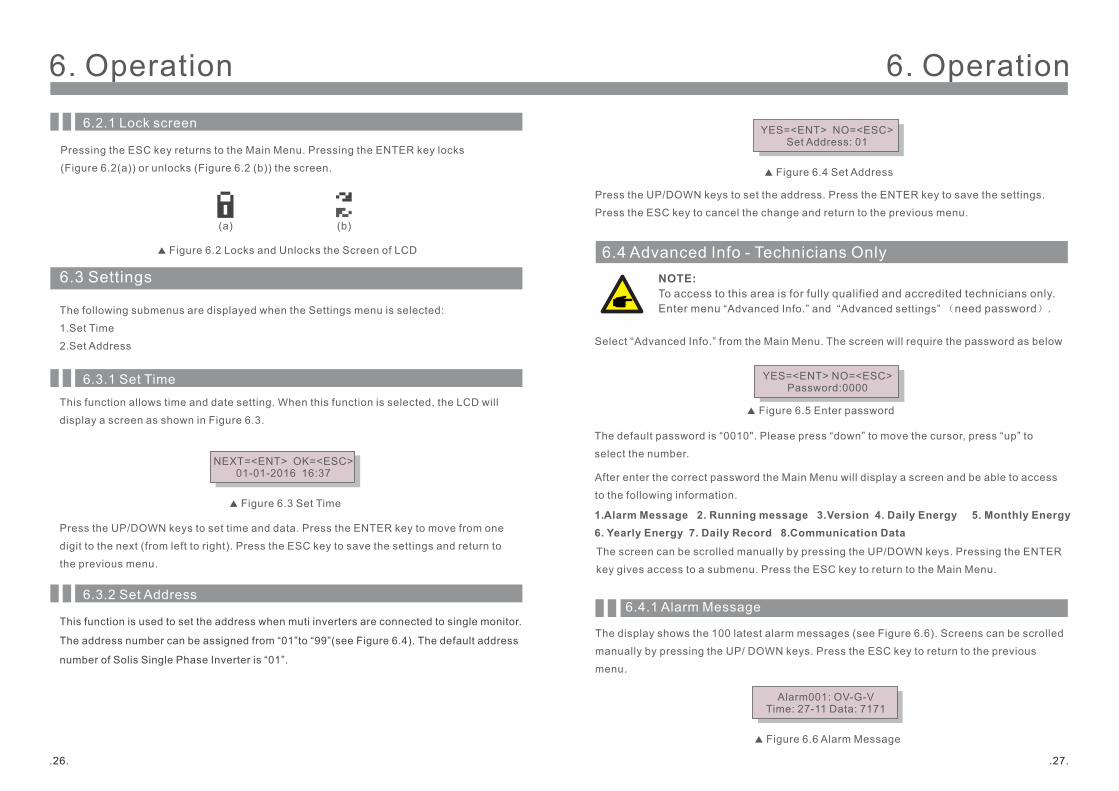
6.3 Settings
The following submenus are displayed when the Settings menu is selected:
1. Set Time
2. Set Address
6.3.1 Set TimeThis function allows time and date setting. When this function is selected, the LCD will
display a screen as shown in Figure 6.3.
NEXT=<ENT> OK=<ESC>01-01-2016 16:37
Figure 6.3 Set Time
Press the UP/DOWN keys to set time and data. Press the ENTER key to move from one
digit to the next (from left to right). Press the ESC key to save the settings and return to
the previous menu.
Figure 6.2 Locks and Unlocks the Screen of LCD
(b)(a)
Pressing the ESC key returns to the Main Menu. Pressing the ENTER key locks
(Figure 6.2(a)) or unlocks (Figure 6.2 (b)) the screen.
5.2 Stop the Inverter
6.2.1 Lock screen
6.3.2 Set Address
This function is used to set the address when muti inverters are connected to single monitor.
The address number can be assigned from “01”to “99”(see Figure 6.4). The default address
number of Solis Single Phase Inverter is “01”.
6.4 Advanced Info - Technicians Only
After enter the correct password the Main Menu will display a screen and be able to access
to the following information.
1. Alarm Message 2. Running message 3.Version 4. Daily Energy 5. Monthly Energy 6. Yearly Energy 7. Daily Record 8. Communication Data
The screen can be scrolled manually by pressing the UP/DOWN keys. Pressing the ENTER
key gives access to a submenu. Press the ESC key to return to the Main Menu.
6.4.1 Alarm Message
The display shows the latest alarm messages (see Figure 6.6). Screens can be scrolled 100
manually by pressing the UP/ DOWN keys. Press the ESC key to return to the previous
menu.
Alarm001: OV-G-VTime: 27-11 Data: 7171
Figure 6.6 Alarm Message
NOTE: To access to this area is for fully qualified and accredited technicians only. Enter menu “Advanced Info.” and “Advanced settings” (need password).
YES=<ENT> NO=<ESC>Password:0000
Figure 6.5 Enter password
Select “Advanced Info.” from the Main Menu. The screen will require the password as below
The default password is “0010". Please press “down” to move the cursor, press “up” to
select the number.
YES=<ENT> NO=<ESC>Set Address: 01
Figure 6.4 Set Address
Press the UP/DOWN keys to set the address. Press the ENTER key to save the settings.
Press the ESC key to cancel the change and return to the previous menu.
6. Operation
.29..28.
6. Operation
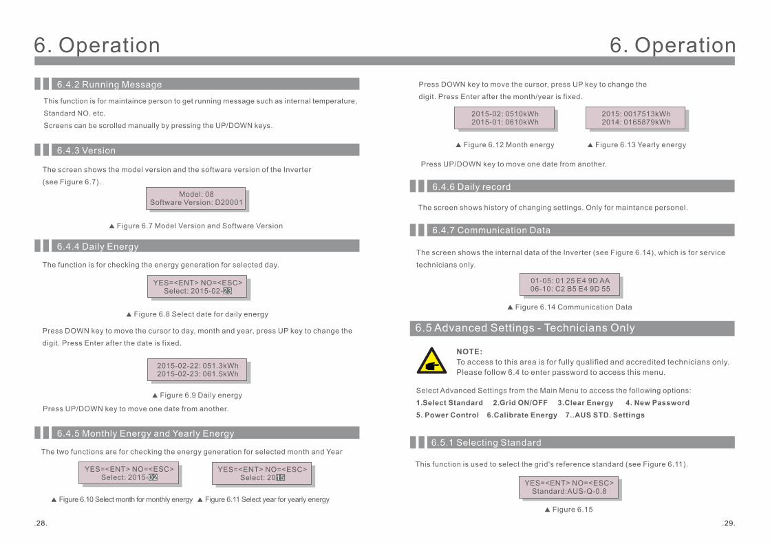
6.4.2 Running Message
6.4.3 Version
The screen shows the model version and the software version of the Inverter
(see Figure 6.7).
Model: 08Software Version: D20001
Figure 6.7 Model Version and Software Version
This function is for maintaince person to get running message such as internal temperature,
Standard NO. etc.
Screens can be scrolled manually by pressing the UP/DOWN keys.
6.4.4 Daily Energy
The function is for checking the energy generation for selected day.
Press DOWN key to move the cursor to day, month and year, press UP key to change the
digit. Press Enter after the date is fixed.
2015-02-22: 051.3kWh2015-02-23: 061.5kWh
Press UP/DOWN key to move one date from another.
6.4.5 Monthly Energy and Yearly Energy
The two functions are for checking the energy generation for selected month and Year
Figure 6.8 Select date for daily energy
Figure 6.9 Daily energy
Figure 6.10 Select month for monthly energy Figure 6.11 Select year for yearly energy
YES=<ENT> NO=<ESC>Select: 2015-02-23
YES=<ENT> NO=<ESC>Select: 2015-02
YES=<ENT> NO=<ESC>Select: 2015
6.4.7 Communication Data
The screen shows the internal data of the Inverter (see Figure 6.14), which is for service
technicians only.
01-05: 01 25 E4 9D AA06-10: C2 B5 E4 9D 55
Figure 6.14 Communication Data
Press DOWN key to move the cursor, press UP key to change the
digit. Press Enter after the month/year is fixed.
2015-02: 0510kWh2015-01: 0610kWh
Press UP/DOWN key to move one date from another.
2015: 0017513kWh2014: 0165879kWh
Figure 6.12 Month energy Figure 6.13 Yearly energy
6.4.6 Daily record
The screen shows history of changing settings. Only for maintance personel.
This function is used to select the grid's reference standard (see Figure 6.11).
YES=<ENT> NO=<ESC>Standard:AUS-Q-0.8
Figure 6.15
6.5.1 Selecting Standard
6.5 Advanced Settings - Technicians Only
Select Advanced Settings from the Main Menu to access the following options:
1. Select Standard 2. Grid ON/OFF 3.Clear Energy 4. New Password 5. Power Control 6.Calibrate Energy 7..AUS STD. Settings
NOTE: To access to this area is for fully qualified and accredited technicians only.Please follow 6.4 to enter password to access this menu.
6. Operation
.31.
6. Operation
.30.
NOTE: This function is for technicians use only.
Press the UP/DOWN keys to select the standard (AS4777, VDE4105, VDE0126, UL-240V-A,
UL-208V-A, UL-240V, UL-208V, MEX-CFE, G83/2 (for 1-3.6kW models), G59/3 (for 4-5kW
models), EN50438 DK, EN50438 IE, EN50438 NL and “User-Def” function). Press the
ENTER key to confirm the setting. Press the ESC key to cancel changes and returns to
previous menu.
Selecting the “User-Def” menu will access to the following submenu (see Figure 6.16),
Figure 6.16
Below is the setting range for “User-Def”. Using this function, the limits can be changed
manually.
NOTE:The " User-Def" function can be only used by the service engineer and must be allowed by the local energy supplier.
OV-G-V1: 220---290V OV-G-F1: 50.2-53Hz(60.2-64Hz)
OV-G-V1-T: 0.1---9S OV-G-F1-T: 0.1---9S
OV-G-V2: 220---290V OV-G-F2: 50.2-53Hz(60.2-64Hz)
OV-G-V2-T: 0.1---1S OV-G-F2-T: 0.1---9S
UN-G-V1: 90---210V UN-G-F1: 47-49.5Hz(56-59.8Hz)
UN-G-V1-T: 0.1---9S UN-G-F1-T: 0.1---9S
UN-G-V2: 90---210V UN-G-F2: 47-49Hz(56-59.8Hz)
UN-G-V2-T: 0.1---1S UN-G-F2-T: 0.1---9S
OV-G-V1: 260V OV-G-V1-T: 1S
Press the UP/DOWN keys to scroll through items. Press the ENTER key to edit the
highlighted item. Press the UP/DOWN keys again to change the setting. Press the ENTER
key to save the setting. Press the ESC key to cancel changes and returns to the previous
menu.
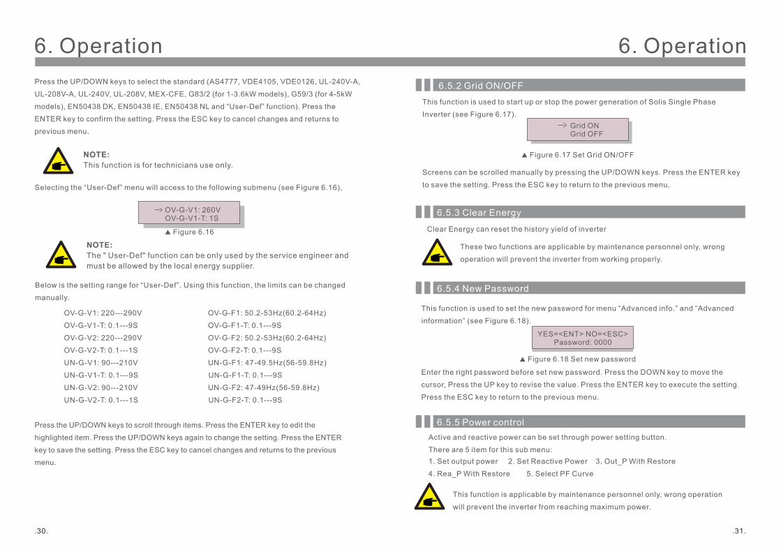
6.5.2 Grid ON/OFFThis function is used to start up or stop the power generation of Solis Single Phase
Inverter (see Figure 6.17). Grid ON
Grid OFF
Figure 6.17 Set Grid ON/OFF
Screens can be scrolled manually by pressing the UP/DOWN keys. Press the ENTER key
to save the setting. Press the ESC key to return to the previous menu.
This function is used to set the new password for menu “Advanced info.” and “Advanced
information” (see Figure 6.18).
Enter the right password before set new password. Press the DOWN key to move the
cursor, Press the UP key to revise the value. Press the ENTER key to execute the setting.
Press the ESC key to return to the previous menu.
6.5.4 New Password
Figure 6.18 Set new password
YES=<ENT> NO=<ESC>Password: 0000
6.5.3 Clear Energy
Clear Energy can reset the history yield of inverter
These two functions are applicable by maintenance personnel only, wrong
operation will prevent the inverter from working properly.
6.5.5 Power controlActive and reactive power can be set through power setting button.
There are 5 item for this sub menu:1. Set output power 2. Set Reactive Power 3. Out_P With Restore
4. Rea_P With Restore 5. Select PF Curve
This function is applicable by maintenance personnel only, wrong operation
will prevent the inverter from reaching maximum power.
6. Operation6. Operation
Maintenance or replacement could clear or cause a different value of total energy. Use this
function could allow user to revise the value of total energy to the same value as before. If
the monitoring website is used the data will be synchronous with this setting automatically.
(see Figure 6.19).
Press the DOWN key to move the cursor, Press the UP key to revise the value. Press the
ENTER key to execute the setting. Press the ESC key to return to the previous menu.
6.5.6 Calibrate Energy
Figure 6.19 Calibrate energy
YES=<ENT> NO=<ESC>Energy:0000000kWh
.33..32.
6.5.7 AUS STD. Settings
This sub menu is enabled when the grid standard is set to AS4777. To comply with New AUS/
NZ 4777.2, Ginlong Solis 4G inverter could set different work mode to work with different
grid requirement.
There are 5 work mode in working mode submenu.
1. Fixed PF 2. Reac. Power 3. Power-PF 4. Volt-Watt 5. Volt-Var.
There are 4 setting under AUS STD settings.
1. Working mode 2. Power Rate limit 3. Freq. Derate set 4. 10mins OV-G-V set.
1. Fixed PFSet PF (-0.8, +0.8), Default 1, Resolution 0.01
2. Reac. PowerSet reacive power (0, 60%), Default 0, Resolution 1%
The parameter in each model could be set as below:
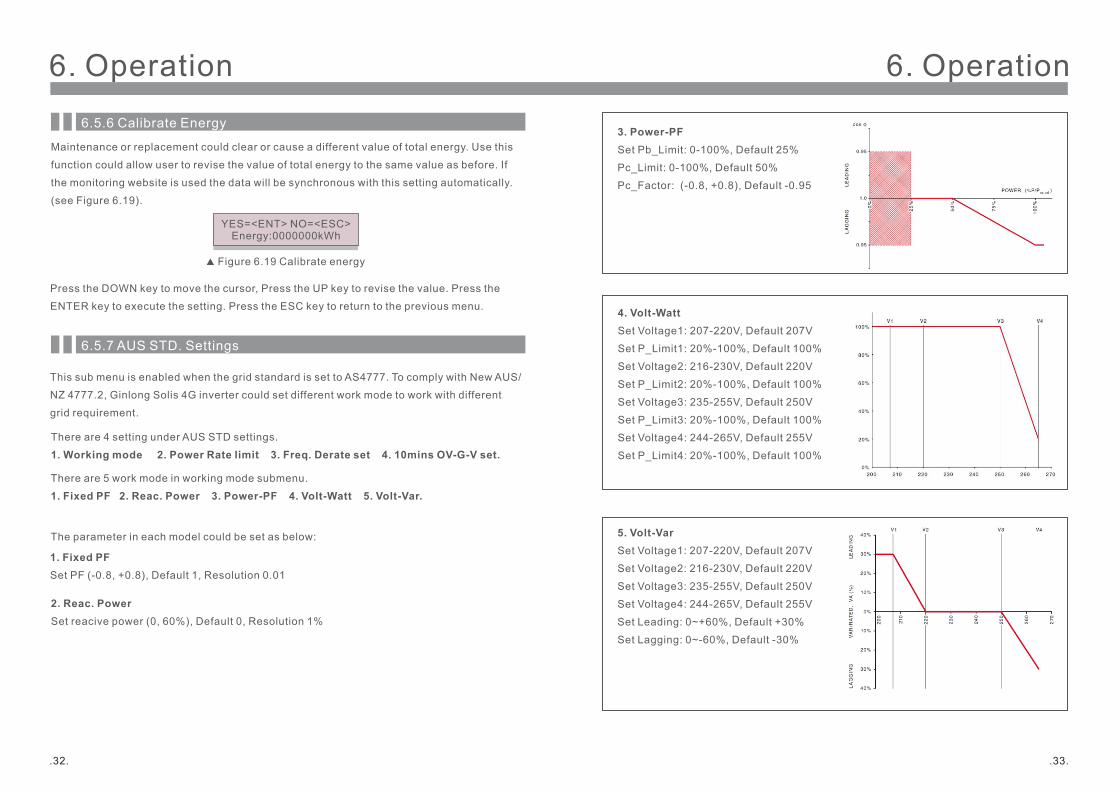
4. Volt-WattSet Voltage1: 207-220V, Default 207V
Set P_Limit1: 20%-100%, Default 100%
Set Voltage2: 216-230V, Default 220V
Set P_Limit2: 20%-100%, Default 100%
Set Voltage3: 235-255V, Default 250V
Set P_Limit3: 20%-100%, Default 100%
Set Voltage4: 244-265V, Default 255V
Set P_Limit4: 20%-100%, Default 100%
5. Volt-VarSet Voltage1: 207-220V, Default 207V
Set Voltage2: 216-230V, Default 220V
Set Voltage3: 235-255V, Default 250V
Set Voltage4: 244-265V, Default 255V
Set Leading: 0~+60%, Default +30%
Set Lagging: 0~-60%, Default -30%
3. Power-PFSet Pb_Limit: 0-100%, Default 25%
Pc_Limit: 0-100%, Default 50%
Pc_Factor: (-0.8, +0.8), Default -0.95
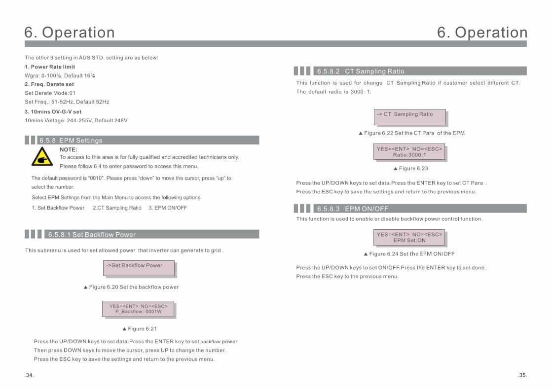
6. Operation6. OperationThe other 3 setting in AUS STD. setting are as below:
1. Power Rate limitWgra: 0-100%, Default 16%2. Freq. Derate setSet Derate Mode:01
Set Freq.: 51-52Hz, Default 52Hz
3. 10mins OV-G-V set10mins Voltage: 244-255V, Default 248V
.35..34.
6.5.8 EPM Settings
Select EPM Settings from the Main Menu to access the following options:
1. Set Backflow Power 2.CT Sampling Ratio 3. EPM ON/OFF
NOTE: To access to this area is for fully qualified and accredited technicians only.
Please follow 6.4 to enter password to access this menu.
The default password is “0010". Please press “down” to move the cursor, press “up” to
select the number.
6.5.8.1 Set Backflow Power
This submenu is used for set allowed power that inverter can generate to grid .
->Set Backflow Power
Figure 6. Set the power 20 backflow
Figure 6.21
YES=<ENT> NO=<ESC>P_Backflow:-0001W
Press the UP/DOWN keys to set data.Press the ENTER key to set backflow power
Then press DOWN keys to move the cursor, press UP to change the number.
Press the ESC key to save the settings and return to the previous menu.
6.5.8.2 CT Sampling Ratio
This function is used for change CT Sampling Ratio if customer select different CT.
The default radio is 3000:1.
-> CT Sampling Ratio
Figure 6.22 Set the CT Para of the EPM
Figure 6.23
YES=<ENT> NO=<ESC>Ratio:3000:1
Press the UP/DOWN keys to set data.Press the ENTER key to set CT Para .
Press the ESC key to save the settings and return to the previous menu.
6.5.8.3 EPM ON/OFF
Figure 6.24 Set the EPM ON/OFF
YES=<ENT> NO=<ESC>EPM Set:ON
Press the UP/DOWN keys to set ON/OFF.Press the ENTER key to set done .
Press the ESC key to the previous menu.
This function is used to enable or disable backflow power control function.
.37..36.
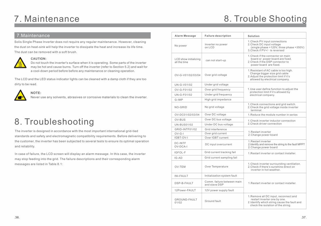
7. Maintenance
8. TroubleshootingThe inverter is designed in accordance with the most important international grid-tied
standards and safety and electromagnetic compatibility requirements. Before delivering to
the customer, the inverter has been subjected to several tests to ensure its optimal operation
and reliability.
In case of failure, the LCD screen will display an alarm message. In this case, the inverter
may stop feeding into the grid. The failure descriptions and their corresponding alarm
messages are listed in Table 8.1:
Solis Single Phase Inverter does not require any regular maintenance. However, cleaning
the dust on heat-sink will help the inverter to dissipate the heat and increase its life time.
The dust can be removed with a soft brush.
CAUTION: Do not touch the inverter's surface when it is operating. Some parts of the inverter may be hot and cause burns. Turn off the inverter (refer to Section 5.2) and wait for a cool-down period before before any maintenance or cleaning operation.
The LCD and the LED status indicator lights can be cleaned with a damp cloth if they are too
dirty to be read.
NOTE: Never use any solvents, abrasives or corrosive materials to clean the inverter.
7.Maintenance
8. Trouble Shooting
Alarm Message
OV-G-V01/02/03/04
OV-G-F01/02
UN-G-F01/02
G-IMP
NO-GRID
OV-DC01/02/03/04
OV-BUS
UN-BUS01/02
GRID-INTF01/02
INI-FAULT
OV-TEM
GROUND-FAULT01/02
Failure description
Over grid voltage
Under grid voltage
Over grid frequency
Under grid frequency
High grid impedance
No grid voltage
Over DC voltage
Over DC bus voltage
Under DC bus voltage
Grid interference
Initialization system fault
Over Temperature
Ground fault
Solution
1.Resistant of AC cable is too high. Change bigger size grid cable2.Adjust the protection limit if it’s allowed by electrical company.
1.Check connections and grid switch.2.Check the grid voltage inside inverter terminal.
1.Reduce the module number in series
1.Restart inverter2.Change power board
1.Check PV input connections2.Check DC input voltage (single phase >120V, three phase >350V)3.Check if PV+/- is reversed
Inverter no power on LCDNo power
LCD show initializing all the time
can not start-up1.Check if the connector on main board or power board are fixed.2.Check if the DSP connector to power board are fixed.
1.Check inverter surrounding ventilation.2.Check if there’s sunshine direct on inverter in hot weather.
1.Remove all DC input, reconnect and restart inverter one by one.2.Identify which string cause the fault and check the isolation of the string.
1.Use user define function to adjust the protection limit if it’s allowed by electrical company.
1.Check inverter inductor connection2.Check driver connection
1.Restart inverter or contact installer.
UN-G-V01/02
DC-INTF DC input overcurrent1.Restart inverter2.Identify and remove the string to the fault MPPT 2.Change power board
IGFOL-F Grid current tracking fail
OV-G-I Over grid current
OV-DCA-I
IGBT-OV-I Over IGBT current
12Power-FAULT 12V power supply fault
1.Restart inverter or contact installer.
IG-AD Grid current sampling fail
DSP-B-FAULT Comm. failure between main and slave DSP
8. Trouble Shooting
.39..38.
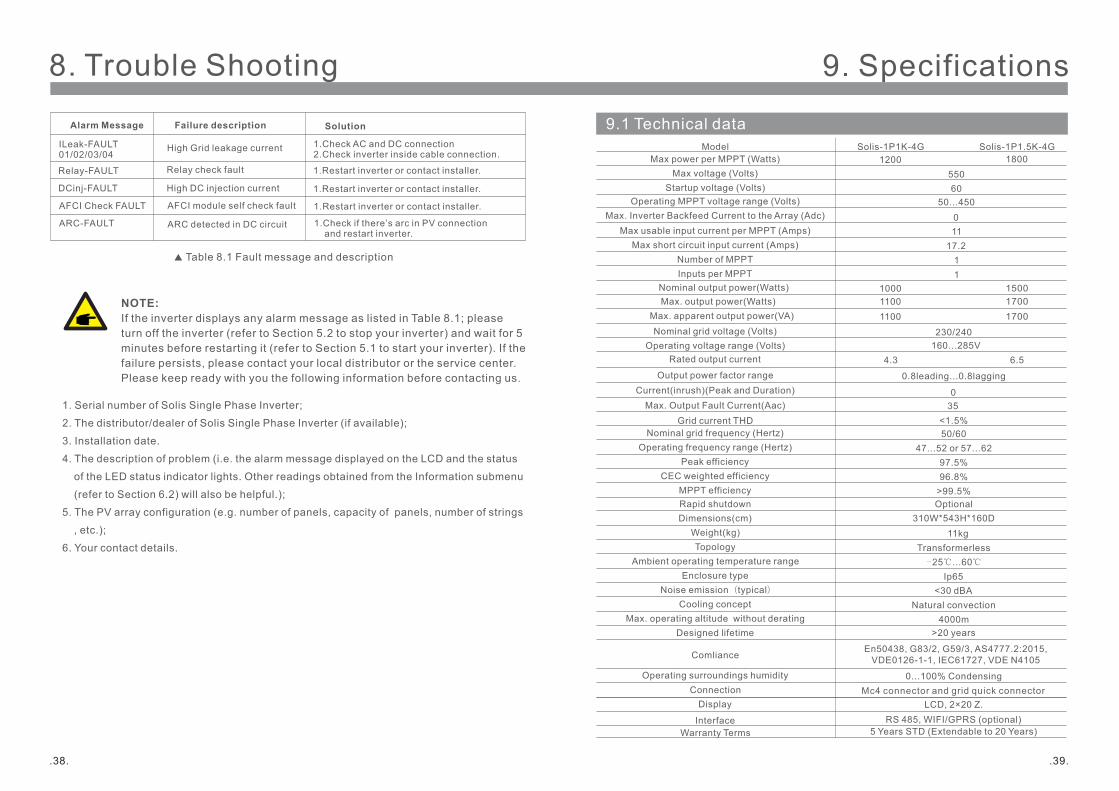
NOTE: If the inverter displays any alarm message as listed in Table 8.1; please turn off the inverter (refer to Section 5.2 to stop your inverter) and wait for 5 minutes before restarting it (refer to Section 5.1 to start your inverter). If the failure persists, please contact your local distributor or the service center. Please keep ready with you the following information before contacting us.
1. Serial number of Solis Single Phase Inverter;
2. The distributor/dealer of Solis Single Phase Inverter (if available);
3. Installation date.
4. The description of problem (i.e. the alarm message displayed on the LCD and the status
of the LED status indicator lights. Other readings obtained from the Information submenu
(refer to Section 6.2) will also be helpful.);
5. The PV array configuration (e.g. number of panels, capacity of panels, number of strings
, etc.);
6. Your contact details.
ILeak-FAULT01/02/03/04
Relay-FAULT
DCinj-FAULT
High Grid leakage current
Relay check fault
High DC injection current
AFCI Check FAULT AFCI module self check fault
1.Check AC and DC connection2.Check inverter inside cable connection.
1.Restart inverter or contact installer.
1.Restart inverter or contact installer.
1.Restart inverter or contact installer.
ARC-FAULT ARC detected in DC circuit 1.Check if there’s arc in PV connection and restart inverter.
Table 8.1 Fault message and description
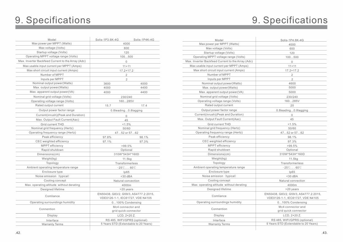
Alarm Message Failure description Solution 9.1 Technical data
Max voltage (Volts)Startup voltage (Volts)
Operating MPPT voltage range (Volts)
Max usable input current per MPPT (Amps) Max short circuit input current (Amps)
Number of MPPT
Nominal output power(Watts)
Nominal grid voltage (Volts)
Rated output current
Output power factor range
Grid current THDNominal grid frequency (Hertz)
Operating frequency range (Hertz)Peak efficiency
CEC weighted efficiencyMPPT efficiency
Max power per MPPT (Watts)
Operating voltage range (Volts)
Rapid shutdown
Model
Dimensions(cm)Weight(kg)Topology
Ambient operating temperature rangeEnclosure type
Noise emission(typical)Cooling concept
Max. operating altitude without deratingDesigned lifetime
Connection
Comliance
Operating surroundings humidity
310W*543H*160DOptional
Solis-1P1K-4G1200
550
50...450
1117.2
1
1000
230/240160...285V
4.3
0.8leading...0.8lagging
<1.5% 50/60
47...52 or 57...6297.5%96.8%
>99.5%
11kgTransformerless
Ip65<30 dBA
Natural convection4000m
>20 years
0...100% CondensingMc4 connector and grid quick connector
Solis-1P1.5K-4G
60
1500
6.5
Inputs per MPPT 1
-25℃...60℃
Display
InterfaceWarranty Terms
LCD, 2×20 Z.RS 485, WIFI/GPRS (optional)
5 Years STD (Extendable to 20 Years)
Max. output power(Watts) 1100 1700
En50438, G83/2, G59/3, AS4777.2:2015, VDE0126-1-1, IEC61727, VDE N4105
1800
Max. Inverter Backfeed Current to the Array (Adc)
Current(inrush)(Peak and Duration)Max. Output Fault Current(Aac)
0
035
Max. apparent output power(VA) 1100 1700
.41..40.
47...52 or 57...62
Max voltage (Volts)Startup voltage (Volts)
Operating MPPT voltage range (Volts)
Max usable input current per MPPT (Amps) Max short circuit input current (Amps)
Number of MPPT
Nominal grid voltage (Volts)
Rated output current
Output power factor range
Grid current THDNominal grid frequency (Hertz)
Operating frequency range (Hertz)Peak efficiency
CEC weighted efficiencyMPPT efficiency
Max power per MPPT (Watts)
Operating voltage range (Volts)
Rapid shutdown
Model
Dimensions(cm)Weight(kg)Topology
Ambient operating temperature rangeEnclosure type
Noise emission(typical)Cooling concept
Max. operating altitude without deratingDesigned lifetime
Connention
Comliance
Operating surroundings humidity
310W*543H*160DOptional
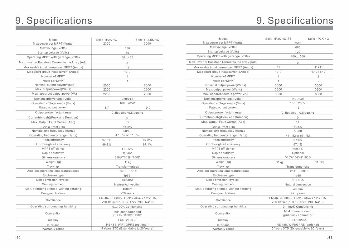
Solis-1P2K-4G3000
550
50...450
1117.2
1
2000
230/240160...285V
8.7
0.8leading~0.8lagging
<1.5% 50/60
97.5%96.8%
>99.5%
11kgTransformerless
Ip65<30 dBA
Natural convection4000m
>20 years
0...100% Condensing
Mc4 connector and grid quick connector
Solis-1P2.5K-4G
60
2500
10.9
Inputs per MPPT 1
-25℃...60℃
Display
InterfaceWarranty Terms
LCD, 2×20 Z.RS 485, WIFI/GPRS (optional)
5 Years STD (Extendable to 20 Years)
2200 2800
EN50438, G83/2, G59/3, AS4777.2:2015, VDE0126-1-1, IEC61727, VDE N4105
2300
97.8%97.1%
Current(inrush)(Peak and Duration)Max. Output Fault Current(Aac)
Max. Inverter Backfeed Current to the Array (Adc)
035
0
Max voltage (Volts)Startup voltage (Volts)
Operating MPPT voltage range (Volts)
Max usable input current per MPPT (Amps) Max short circuit input current (Amps)
Number of MPPT
Nominal grid voltage (Volts)
Rated output current
Output power factor range
Grid current THDNominal grid frequency (Hertz)
Operating frequency range (Hertz)Peak efficiency
CEC weighted efficiencyMPPT efficiency
Max power per MPPT (Watts)
Operating voltage range (Volts)
Rapid shutdown
Model
Dimensions(cm)Weight(kg)Topology
Ambient operating temperature rangeEnclosure type
Noise emission(typical)Cooling concept
Max. operating altitude without deratingDesigned lifetime
Connention
Comliance
Operating surroundings humidity
310W*543H*160DOptional
Solis-1P3K-4G
600
100....500
11+1117.2+17.2
2
3000
230/240160...285V
0.8leading...0.8lagging
<1.5% 50/60
97.8%97.1%
>99.5%
11kgTransformerless
Ip65<30 dBA
Natural convection4000m
>20 years
0...100% CondensingMc4 connector and
grid quick connector
Solis-1P3K-4G-ST
120
3000
13
Inputs per MPPT 2
-25℃...60℃
Display
InterfaceWarranty Terms
LCD, 2×20 Z.RS 485, WIFI/GPRS (optional)
5 Years STD (Extendable to 20 Years)
33003300
3500
11 17.2
11
47...52 or 57...62
Max. Inverter Backfeed Current to the Array (Adc)
Current(inrush)(Peak and Duration)Max. Output Fault Current(Aac)
045
0
11.5kg
Nominal output power(Watts) Max. output power(Watts)
Max. apparent output power(VA)
Nominal output power(Watts) Max. output power(Watts)
Max. apparent output power(VA) 2200 2800 33003300
EN50438, G83/2, G59/3, AS4777.2:2015, VDE0126-1-1, IEC61727, VDE N4105
.43..42.
Max voltage (Volts)Startup voltage (Volts)
Operating MPPT voltage range (Volts)
Max usable input current per MPPT (Amps) Max short circuit input current (Amps)
Number of MPPT
Nominal grid voltage (Volts)
Rated output current
Output power factor range
Grid current THDNominal grid frequency (Hertz)
Operating frequency range (Hertz)Peak efficiency
CEC weighted efficiencyMPPT efficiency
Max power per MPPT (Watts)
Operating voltage range (Volts)
Rapid shutdown
Model
Dimensions(cm)Weight(kg)
TopologyAmbient operating temperature range
Enclosure typeNoise emission(typical)
Cooling conceptMax. operating altitude without derating
Designed lifetime
Connention
Comliance
Operating surroundings humidity
310W*543H*160DOptional
Solis-1P3.6K-4G4000600
100...500
11+1117.2+17.2
2
3600
230/240160...285V
15.7
0.8leading...0.8lagging
<1.5% 50/60
47...52 or 57...6298.1%97.3%
>99.5%
Transformerless
Ip65<30 dBA
Natural convection4000m
>20 years
0...100% CondensingMc4 connector and
grid quick connector
Solis-1P4K-4G
120
4000
17.4
Inputs per MPPT 2
-25℃...60℃
Display
InterfaceWarranty Terms
LCD, 2×20 Z.RS 485, WIFI/GPRS (optional)
5 Years STD (Extendable to 20 Years)
4000 4400
97.8%97.1%
Max. Inverter Backfeed Current to the Array (Adc)
Current(inrush)(Peak and Duration)Max. Output Fault Current(Aac)
045
0
Max voltage (Volts)Startup voltage (Volts)
Operating MPPT voltage range (Volts)
Max usable input current per MPPT (Amps) Max short circuit input current (Amps)
Number of MPPT
Nominal grid voltage (Volts)
Rated output current
Output power factor range
Grid current THDNominal grid frequency (Hertz)
Operating frequency range (Hertz)Peak efficiency
CEC weighted efficiencyMPPT efficiency
Max power per MPPT (Watts)
Operating voltage range (Volts)
Rapid shutdown
Model
Dimensions(cm)Weight(kg)Topology
Ambient operating temperature rangeEnclosure type
Noise emission(typical)Cooling concept
Max. operating altitude without deratingDesigned lifetime
Connention
Comliance
Operating surroundings humidity
310W*543H*160DOptional
4000600
100...500
11+1117.2+17.2
2
230/240160...285V
0.8leading...0.8lagging
<1.5% 50/60
47...52 or 57...6298.1%97.3%
>99.5%
11.5kgTransformerless
Ip65<30 dBA
Natural convection4000m
>20 years
0...100% CondensingMc4 connector and
grid quick connector
120
4600Inputs per MPPT 2
-25℃...60℃
Display
InterfaceWarranty Terms
LCD, 2×20 Z.RS 485, WIFI/GPRS (optional)
5 Years STD (Extendable to 20 Years)
5000
Solis-1P4.6K-4G
20
Max. Inverter Backfeed Current to the Array (Adc)
Current(inrush)(Peak and Duration)Max. Output Fault Current(Aac)
045
0
11.5kg
Nominal output power(Watts) Max. output power(Watts)
Max. apparent output power(VA)
Nominal output power(Watts) Max. output power(Watts)
Max. apparent output power(VA) 4000 4400 5000
EN50438, G83/2, G59/3, AS4777.2:2015, VDE0126-1-1, IEC61727, VDE N4105
EN50438, G83/2, G59/3, AS4777.2:2015, VDE0126-1-1, IEC61727, VDE N4105
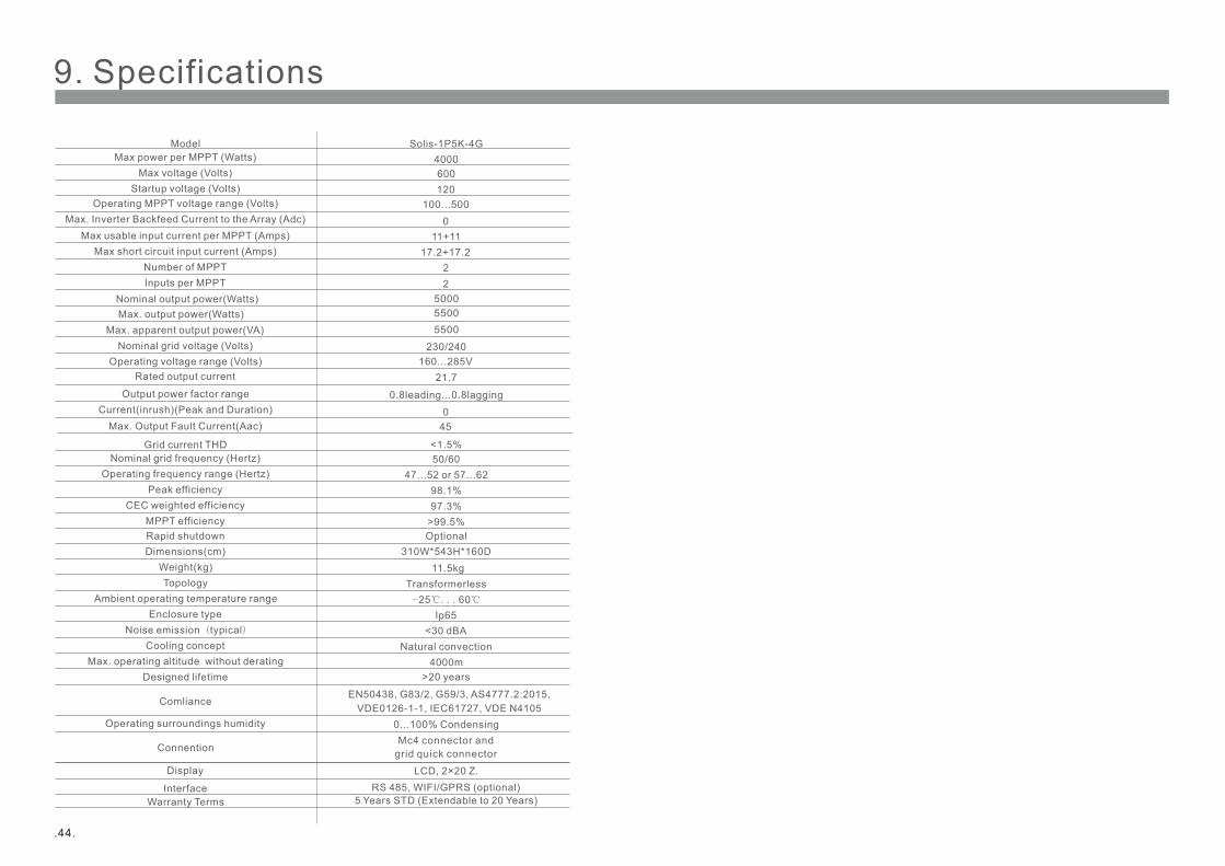
.44.
Max voltage (Volts)Startup voltage (Volts)
Operating MPPT voltage range (Volts)
Max usable input current per MPPT (Amps) Max short circuit input current (Amps)
Number of MPPT
Nominal grid voltage (Volts)
Rated output current
Output power factor range
Grid current THDNominal grid frequency (Hertz)
Operating frequency range (Hertz)Peak efficiency
CEC weighted efficiencyMPPT efficiency
Max power per MPPT (Watts)
Operating voltage range (Volts)
Rapid shutdown
Model
Dimensions(cm)Weight(kg)Topology
Ambient operating temperature rangeEnclosure type
Noise emission(typical)Cooling concept
Max. operating altitude without deratingDesigned lifetime
Connention
Comliance
Operating surroundings humidity
310W*543H*160DOptional
600
100...500
11+1117.2+17.2
2
230/240160...285V
0.8leading...0.8lagging
<1.5% 50/60
47...52 or 57...6298.1%97.3%
>99.5%
11.5kgTransformerless
Ip65<30 dBA
Natural convection4000m
>20 years
0...100% CondensingMc4 connector and
grid quick connector
Solis-1P5K-4G
120
21.7
Inputs per MPPT 2
-25℃...60℃
Display
InterfaceWarranty Terms
LCD, 2×20 Z.RS 485, WIFI/GPRS (optional)
5 Years STD (Extendable to 20 Years)
5500
4000
Max. Inverter Backfeed Current to the Array (Adc)
Current(inrush)(Peak and Duration)Max. Output Fault Current(Aac)
045
0
5000Nominal output power(Watts) Max. output power(Watts)
Max. apparent output power(VA) 5500
EN50438, G83/2, G59/3, AS4777.2:2015, VDE0126-1-1, IEC61727, VDE N4105