
PV-250 Vital Plug-In AC Vane Relay · The relay is factory calibrated to operate across a wide...
38
SM 4574C 1000 Technology Drive, Pittsburgh, PA 15219 645 Russell Street, Batesburg, SC 29006 Installation, Operation, and Maintenance PV-250 Vital Plug-In AC Vane Relay for Track Circuit Applications STS USA Part Numbers N342555- 003 803 903 THIS MANUAL SUPERCEDES SM-4574-C DATED FEBRUARY 1985
Transcript of PV-250 Vital Plug-In AC Vane Relay · The relay is factory calibrated to operate across a wide...

SM 4574C 1000 Technology Drive, Pittsburgh, PA 15219 645 Russell Street, Batesburg, SC 29006
Installation, Operation, and Maintenance
PV-250 Vital Plug-In AC Vane Relay
for Track Circuit Applications
STS USA Part Numbers N342555- 003 803 903
THIS MANUAL SUPERCEDES SM-4574-C DATED FEBRUARY 1985

PV-250 Vital Plug-In AC Vane Relay
Copyright 2019 SM 5924 Rev. 2, March 2019

PV-250 Vital Plug-In AC Vane Relay
Copyright 2019 SM 4574-C Rev. 2 March 2019 i
Proprietary Notice This document and its contents are the property of Hitachi Rail STS USA, Inc. (formerly known as Union Switch & Signal Inc., and hereinafter referred to as "STS USA"). This document is furnished to you on the following conditions: 1.) That no proprietary or intellectual property right or interest of STS USA is given or waived in supplying this document and its contents to you; and, 2.) That this document and its contents are not to be used or treated in any manner inconsistent with the rights of STS USA, or to its detriment, and are not to be copied, reproduced, disclosed or transferred to others, or improperly disposed of without the prior written consent of STS USA.
Important Notice STS USA constantly strives to improve our products and keep our customers apprised of changes in technology. Following the recommendations contained in the attached service manual will provide our customers with optimum operational reliability. The data contained herein purports solely to describe the product, and does not create any warranties. Within the scope of the attached manual, it is impossible to take into account every eventuality that may arise with technical equipment in service. Please consult an STS USA local sales representative in the event of any irregularities with our product. STS USA expressly disclaims liability resulting from any improper handling or use of our equipment, even if these instructions contain no specific indication in this respect. We strongly recommend that only approved STS USA spare parts are used as replacements.
Copyright© 2019, Hitachi Rail STS USA, Inc. 1000 Technology Drive, Pittsburgh, PA USA 15219-3120
645 Russell Street, Batesburg, SC 29006 sts.hitachirail.com All rights reserved.

PV-250 Vital Plug-In AC Vane Relay
Copyright 2019 SM 4574-C Rev. 2 March 2019 ii
Revision History REV. ISSUE DATE REVISION DESCRIPTION
0 May, 1986 Original Issue 1 November, 1986 Revised 2 March 2019 Hitachi Rail STS Branding

PV-250 Vital Plug-In AC Vane Relay
Copyright 2019 SM 4574-C Rev. 2 March 2019 iii
Table of Contents 1. GENERAL INFORMATION ............................................................................................................... 1-1
1.1. Introduction ............................................................................................................................... 1-1 1.2. Description ................................................................................................................................ 1-1
1.2.1. General ......................................................................................................................... 1-1 1.2.2. Coils .............................................................................................................................. 1-1 1.2.3. Contacts ........................................................................................................................ 1-1
1.3. SPECIFICATIONS .................................................................................................................... 1-2 1.3.1. Electrical ....................................................................................................................... 1-2 1.3.2. Mechanical .................................................................................................................... 1-2 1.3.3. Mechanical .................................................................................................................... 1-2
2. INSTALLATION ................................................................................................................................. 2-1 2.1. GENERAL ................................................................................................................................. 2-1
2.1.1. Care In Handling ........................................................................................................... 2-1 2.2. MOUNTINGBASE ..................................................................................................................... 2-1 2.3. RELAY INDEXING .................................................................................................................... 2-1 2.4. RECEPTACLE CONTACT SPRINGS ...................................................................................... 2-2
2.4.1. Old Style Base Only ...................................................................................................... 2-2 2.4.2. Improved One Piece Base Only ................................................................................... 2-3 2.4.3. Installing Wires In Receptacle Contact Springs ............................................................ 2-4
2.5. RELAY INSERTION ................................................................................................................. 2-4 3. FIELD MAINTENANCE ..................................................................................................................... 3-1
3.1. INTRODUCTION ...................................................................................................................... 3-1 3.2. PERIODIC PERFORMANCE TEST ......................................................................................... 3-1
3.2.1. Cleaning ........................................................................................................................ 3-1 3.2.2. Service Requirements .................................................................................................. 3-1
3.2.2.1. General........................................................................................................... 3-1 3.2.2.2. In-Service Test ............................................................................................... 3-1 3.2.2.3. Test Procedures ............................................................................................. 3-1
4. SHOP MAINTENANCE ..................................................................................................................... 4-1 4.1. INTRODUCTION ...................................................................................................................... 4-1 4.2. CLEANING AND INSPECTION ................................................................................................ 4-1
4.2.1. Cleaning Relay Contacts .............................................................................................. 4-1 4.2.1.1. General........................................................................................................... 4-1 4.2.1.2. Contact Cleaning Procedure .......................................................................... 4-2
4.2.2. Cleaning Relay Contacts (Alternate) ............................................................................ 4-3 4.2.2.1. Contacts That Are Severely Burned .............................................................. 4-3 4.2.2.2. Contacts With Heavy Tarnish, Slightly Rough or Pitted ................................. 4-3 4.2.2.3. Contacts With Surface Film or Oxidation (Not Pitted) .................................... 4-3
4.3. CHECK-OUT PROCEDURE (Performance Test) .................................................................... 4-3 4.4. REPAIRS AND REPLACEMENT ............................................................................................. 4-4
4.4.1. Recommended Tools and Test Equipment .................................................................. 4-4 4.4.2. Disassembly .................................................................................................................. 4-4
4.4.2.1. Vane Assembly Removal ............................................................................... 4-4 4.4.3. Reassembly .................................................................................................................. 4-5

PV-250 Vital Plug-In AC Vane Relay
Copyright 2019 SM 4574-C Rev. 2 March 2019 iv
4.4.3.1. Installing Vane Assembly ............................................................................... 4-5 4.4.3.2. Installing Operating Arms ............................................................................... 4-5
4.4.4. General Parts Replacement ......................................................................................... 4-7 4.4.4.1. Replacing Contact Block ................................................................................ 4-7
4.5. ADJUSTMENTS ....................................................................................................................... 4-7 4.5.1. Recommended Tools .................................................................................................... 4-8 4.5.2. Contact Adjustments ..................................................................................................... 4-8
4.5.2.1. Initial Contact Adjustment .............................................................................. 4-8 4.5.2.2. Final Contact Adjustments ............................................................................. 4-8
4.5.3. Counterweight Adjustment ............................................................................................ 4-9 4.6. CALIBRATION ........................................................................................................................ 4-10
4.6.1. Recommended Test Equipment ................................................................................. 4-10 4.6.2. Procedure ................................................................................................................... 4-10
4.7. CALIBRATION REQUIREMENTS .......................................................................................... 4-12 4.7.1. Test for Balanced Magnetic Circuit ............................................................................. 4-12 4.7.2. In-Service Test ............................................................................................................ 4-12 4.7.3. Contact Resistance ..................................................................................................... 4-13
APPENDIX-A. PARTS LIST ................................................................................................................ A-1
List of Figures Figure 2-1. Typical Plug-In Relay and Mounting Base .............................................................................. 2-2 Figure 2-2. Receptacle Contact Spring Installed ....................................................................................... 2-3 Figure 4-1. Adjustment of Heel Spring Clips .............................................................................................. 4-6 Figure 4-2. Method of Closing in of Lower Heel Spring Clips .................................................................... 4-6 Figure 4-3. Application of Bending Tools ................................................................................................... 4-7 Figure 4-4. Adjustable Torque Arm ............................................................................................................ 4-9 Figure 4-5. AC Vane Relay Test Circuit ................................................................................................... 4-11 Figure A-1. PV-250 Relay Assembly .........................................................................................................A-3 Figure A-2. Vane Assembly .......................................................................................................................A-4 Figure A-3. Old Style Mounting Base .........................................................................................................A-6 Figure A-4. Improved Mounting Base ........................................................................................................A-8
List of Tables Table 4-1. Test Operating Values ................................................................................................... 4-12 Table 4-2. Operating Values at Ideal Phase Relations ................................................................... 4-12

PV-250 Vital Plug-In AC Vane Relay
Copyright 2019 SM 4574-C Rev. 2 March 2019 1-1
1. GENERAL INFORMATION 1.1. Introduction This manual covers the PV-250 plug-in AC vane relay used for track circuit applications. Since the relay is a two element AC vane type, it must be provided with the appropriate equipment to provide the adequate phase displacement between the local and control (track windings). The earlier and later designed relays have the same operating characteristics and fit into the same mounting base. The design of the PV-250 relay conforms to all applicable AAR specifications. 1.2. Description 1.2.1. General The relay is factory calibrated to operate across a wide environmental range. All moving parts are enclosed in a sturdy, transparent, dust and moisture resistant cover. To ensure the relay is inserted in its proper mounting base all relays have indexing pins. Relays lock securely in the plug-in position 1.2.2. Coils This relay uses single wound coils for the control and local elements that present the impedance to meet the specifications of paragraph 1.3.1. 1.2.3. Contacts Contacts of the PV-250 relay are standard low voltage silver-to-silver impregnated carbon front and silver-to-silver back. See Figure A-1 (in the appendix) for a pictorial representation of the contact assembly.

PV-250 Vital Plug-In AC Vane Relay
Copyright 2019 SM 4574-C Rev. 2 March 2019 1-2
1.3. SPECIFICATIONS The following paragraphs provide the electrical and mechanical specifications of the PV-250 relays covered in this manual. 1.3.1. Electrical Relay electrical specifications are tabulated below:
Operating Values at Ideal Phase Relations Part Number P. U. +/- 5% Full Stroke Min.
D. A. % of P. U.
Local With
Front Testing
Without Front
Testing Contacts Amps Volts Amps Volts Voltage/Hz N342555- 003 803, 903 2F, 2B 0.28 0.70 0.327 0.82 90 115/60
Contacts: standard low voltage silver-to-silver impregnated carbon fronts, and silver-to-silver backs.
Contact Assignments: Type Number F 2, 3 B 7, 8 The above values are based on ideal phase relations, track volts lead line volts 90° and track amperes lead line volts 24°.
1.3.2. Mechanical The following mechanical specifications are common to all PV-250 relays covered in this manual. 1.3.3. Mechanical The following mechanical specifications are common to all PV-250V relays covered in this manual.
Dimensions Height 7-1/16" (17.93 cm) Width 4-15/16" (12.54 cm) Depth 8-3/8" (21.27 cm)
Temperature -40°F (-40°C) to +185°F (85°C)
Indexing Relay part number determines indexing plate required. (Refer to Section 2.3)
Weight 8.0 Lbs. (3.63 Kg.)
Mounting Base Mounting Base N386458 (Old Style) – 37 oz. Mounting Base N438689 (New Style) – 28 oz.
Mounting Base Dimensions
Height 7-15/16" (20.16 cm) Width 4-15/16" (12.54 cm) Depth 2-7/16" (6.19 cm) (Old-Style Base) Depth 1-25/32" (4.52 cm) (Improved Base)

PV-250 Vital Plug-In AC Vane Relay
Copyright 2019 SM 4574-C Rev. 2 March 2019 2-1
2. INSTALLATION 2.1. GENERAL Relays plug directly into a mounting base which is secured to a rack. The only installation instructions required are for the mounting base. 2.1.1. Care In Handling It is very important that these vane relays be handled carefully in order that no undue stresses are applied to the vane structure, which might throw the vane out of adjustment. A piece of twine, which firmly holds the vane, is applied to the relay when it leaves the factory. The twine must be removed when the relay is placed in service. 2.2. MOUNTINGBASE Secure the mounting base directly to the rack using the hardware furnished. All wiring terminates at the rear of the mounting base to solderless terminals (contact receptacles). Mounting base details are shown in the appendix. 2.3. RELAY INDEXING Relays are factory equipped with indexing pins to prevent insertion of an incorrect relay into a mounting base. Each relay is accompanied by an indexing plate which is applied to the mounting base at the time of initial installation. A typical plug-in relay with indexing pins and base with corresponding indexing plate is shown in Figure 2-1. The following data defines the indexing that has been established for relays covered by this manual:
a. The index code always consists of four figures (such as 0001, 0002, or 0101) and is used for both the relay and the indexing plate on the mounting base.
b. The index code for each relay can be determined from the relay part number and its suffix which is marked on the name plate attached to the front of the relay. The first two digits of the index code are the last two digits of the part number, and the second two digits of the index code are the last two digits of the suffix. The index number thus obtained should agree with the placement of the indexing pins in the numbered vertical rows on the back of the relay starting with the top pin and reading down.
c. The index code for each mounting base is determined by the placement of the holes in the numbered vertical rows of the large white nylon indexing plate which is affixed to the front of the mounting base. This indexing plate should not be removed from the mounting base unless it is damaged or the indexing is to be purposely changed to accommodate a relay of a different part number. Discard the indexing plate which comes in a bag tied to the handle of all new relays unless it is needed for replacement or damaged indexing plate or for application to a new mounting base.

PV-250 Vital Plug-In AC Vane Relay
Copyright 2019 SM 4574-C Rev. 2 March 2019 2-2
WARNING
Never drill new holes in a base indexing plate which will permit application of relays with different part numbers or change indexing pins on the back of a relay unless it is being converted to a new part number. Otherwise, a hazard will be created which may compromise safety circuit functions.
Figure 2-1. Typical Plug-In Relay and Mounting Base 2.4. RECEPTACLE CONTACT SPRINGS 2.4.1. Old Style Base Only The N386458 mounting base will normally be equipped with the required quantity of J680165 solderless receptacle contact springs, and will accommodate one or two #14 or #16wires. It can, however, be equipped with receptacle contact springs for one or two #10 or #12 wires (J680181), or for one or two #18 or #20 wires (J680179). Make certain which type of solderless receptacle contact springs accompany the mounting base before proceeding with their installation.
INDEXING PINS (4)
MOUNTING BASE
INDEXING PLATE
FLAT PIN CONTACTS
MODULE
4C5.
0002
.00

PV-250 Vital Plug-In AC Vane Relay
Copyright 2019 SM 4574-C Rev. 2 March 2019 2-3
2.4.2. Improved One Piece Base Only The new one piece mounting base with hardware includes a full complement of receptacle contact springs (M451142-2702) to accommodate one or two #14-#16 wires, mounting fasteners, and tags. It can, however, be equipped with receptacle contact springs for one or two #l0-#12 wires (M451142-2703), or for one or two #18-#20 (M451142-2701). Make certain which type of solderless receptacle contact springs accompany the mounting base before proceeding with their installation. Each solderless receptacle contact springs should be inspected for physical damage before proceeding with installation. The following is recommended when installing solderless receptacle contact springs after crimping wire:
a. Receptacle contact springs must be inserted into the base with the lock side down or lanced tab up (refer to Figure 2-2).
b. Make certain that the lanced tab is slightly compressed as the receptacle contact spring is inserted along the top of the cavity. The lanced tab could have been bent during handling, and therefore would not provide the required contact pressure after the relay is inserted. If the lanced tab does not touch, pull it up slightly using fingers or a suitable tool.
c. After insertion, pull firmly on the wire make certain the receptacle contact spring is locked in the cavity.
Figure 2-2. Receptacle Contact Spring Installed
RECEPTACLE
SPRINGCONTACT
RECEPTACLE
SPRINGCONTACT
LOCK SIDE LOCK SIDE
OLD MOUNTING BASE IMPROVED MOUNTING BASE4C5.
0003
.00

PV-250 Vital Plug-In AC Vane Relay
Copyright 2019 SM 4574-C Rev. 2 March 2019 2-4
2.4.3. Installing Wires In Receptacle Contact Springs Use the following procedure to ensure a good electrical and mechanical connection between the conductor wire and the receptacle contact spring. The following table identifies the correct crimping tool to be used when installing wires in receptacle contact spring.
Crimping Tool
Wire Size
Old Style Receptacl
e C t t S i
Improved Base
Receptacle
(Amp Type)
J397138 J397139 J397188
#10/#12 AWG #14/#16 AWG #18/#20 AWG
J680181 J680165 (Std) J680179
M451142-2703 M451142-2702 M451142-2701
a. Strip 3/16 in. (0.187 in. or 0.47 cm.) of insulation from the end of the wire. b. Place the receptacle contact spring into the jaws of the proper crimping tool.
When using only one terminal, of any wire size, use the shortest terminal. c. Partially close the crimping tool jaws against the receptacle contact spring to hold
it in place. (Do not crush the receptacle contact spring barrel at this time.) d. Insert the stripped end of wire all the way into the receptacle contact spring
barrel. Squeeze the tool handles until crimping is completed and the jaws release. When using both terminals, it is more convenient to attach the first wire to the longest terminal.
e. Remove the crimped receptacle contact spring from the tool and inspect the connection. Make certain that the wire is flush with the crimped barrel and that there are no loose strands of wire.
2.5. RELAY INSERTION Orient the relay to the mounting base with the name plate right side up; then plug the relay into the base. The relay should be pushed firmly against the mounting base while depressing the latch rod. After the relay is completely seated in the base, release the latch rod and pull on the handle to ensure that the relay has locked in place.

PV-250 Vital Plug-In AC Vane Relay
Copyright 2019 SM 4574-C Rev. 2 March 2019 3-1
3. FIELD MAINTENANCE 3.1. INTRODUCTION This section provides the necessary periodic preventive maintenance procedures which must be performed to ensure continuous, continuous, proper, and efficient operation of the PV-250 style relays covered in this manual. Field maintenance covers periodic inspections and performance tests. 3.2. PERIODIC PERFORMANCE TEST 3.2.1. Cleaning Before inspecting and testing the relay, if necessary use a soft cloth to clean the exterior to remove any dirt or dust that may have collected. A safe cleaning solution of alcohol and water or common laundry detergent may be used for removal of accumulated, dirt, grease, etc. 3.2.2. Service Requirements 3.2.2.1. General
All vital relays must be inspected and tested at least every two (2) years. The tests and inspections are to include: pick-up current, drop-away current, timing of slow operating and timing relays; and visual inspection of contacts for damage or misalignment, corrosion or other contamination of parts, loose parts inside of the cover, broken seal, and cracked or broken cover. Relays not passing the above stated tests and inspections must be replaced and not returned to service until the operating characteristics and conditions are in accordance with STS USA specifications. 3.2.2.2. In-Service Test
It is recommended that track relays in service be removed from service for shop repairs when the drop-away value falls below 80% of the actual pick-up value (refer to Table 4-1 for calibration values). 3.2.2.3. Test Procedures
Test the operating characteristics of the PV-250 style relays as described in Section 4.6 in this manual.

PV-250 Vital Plug-In AC Vane Relay
Copyright 2019 SM 4574-C Rev. 2 March 2019 3-2

PV-250 Vital Plug-In AC Vane Relay
Copyright 2019 SM 4574-C Rev. 2 March 2019 4-1
4. SHOP MAINTENANCE 4.1. INTRODUCTION This section provides the information necessary to perform shop level repairs of the PV-250 style relays covered in this manual. In general, relays arriving at the shop for repair have been checked in the field and have been found to perform unacceptably or have been physically damaged. 4.2. CLEANING AND INSPECTION Before inspecting the relay and initiating repairs, use a soft cloth to clean the exterior carefully to remove any dirt or dust that may have collected. A safe cleaning solution of alcohol and water may be used for removal of accumulated dirt, grease, etc. Inspect the relay exterior for signs of physical damage, such as cracked or broken cover, cracked or damaged housing, and damaged and or missing contact block terminals and indexing pins. If severe external damage is found, a careful inspection of the interior components should be made for obvious physical damage. Proceed with relay contact cleaning, using the following recommended cleaning materials:
Recommended Cleaning Materials Order Reference Cleaning Tool N378099 Extra sleeving for recovering three metal strips J772330 #4/0 Metallographic paper sheet 9" x 14" J035215 Burnishing Tool J397187 Distilled Water --
4.2.1. Cleaning Relay Contacts This section covers recommended methods for the preparation and cleaning of relay contacts. After contacts have been dressed and/or after adjustments have been made to meet calibration requirements, the contacts should be cleaned in accordance with the procedure given in paragraph 4.2.1.1 and 4.2.1.2. Due to the possible unavailability of the sleeving (J772330) for the cleaning tool (N378099), an alternate contact cleaning procedure is presented in Paragraph 4.2.2.
CAUTION
If it is desired to, use an aerosol spray for cleaning relay contacts, only Virgin Freon TF (available from Miller Stephenson chemical company as MS-180 or MS-230 contact Re-Nu Freon TF) is approved by STS USA.
4.2.1.1. General
a. Preliminary Information

PV-250 Vital Plug-In AC Vane Relay
Copyright 2019 SM 4574-C Rev. 2 March 2019 4-2
The cleaning tool should be used to clean no more than 12 front and 12 back contacts, after which they should be washed before re-use. The cleaning tool should be cleaned using a mild soap or detergent and water, rinsing thoroughly and allowing to dry.
NOTE
In the final cleaning procedures outlined in the following sections, it is recommended that all silver contacts be cleaned first and then all silver impregnated carbon contacts in order not to contaminate the silver tips with residue that might adhere to the cleaning tool from cleaning the silver impregnated carbon contacts.
b. New Sleeving To apply new sleeving to the cleaning tool, heat-seal one end by placing in a flame and pinching quickly with pliers. Stretch the sleeving over the cleaning tool and cut off excess material 1/8" beyond the end of the tool. Keeping the material stretched, heat-seal the second end. Wash the tool before using if it does not appear to be perfectly clean.
4.2.1.2. Contact Cleaning Procedure
a. Apply distilled water (dispensed from a clean closed container) to a clean cleaning tool, and wash the back contact tip members while applying pressure by holding the contacts closed. Wipe the contacts with at least six short strokes of the tool.
b. Immediately after the washing, the contacts should be wiped dry using a second clean, lint-free cleaning tool. This "dry wipe" removes or loosens any residue, such as dust, which was left from step ‘a’. Wipe the contacts with at least six short strokes of the tool.
c. Apply more distilled water to the same tool and wipe the front contacts. Immediately wipe these contacts dry with the same dry cleaning tool as was previously used.
d. Immediately blow the contacts with filtered compressed air to remove any loose dust.
e. The washing and drying tools should then be washed before re-use. f. If the contact resistance is still too high, burnish the contacts with metallographic
paper cut in strips 1/2 inch wide and repeat steps ‘a’ to ‘d’ to remove the dust formed.
g. If the contacts are burned or pitted and the operation per step ‘f’ does not successfully reduce the contact resistance, burnish the contacts in the direction of slide with burnishing tool J397187. Follow with metallographic paper and repeat steps ‘a’ to ‘d’ to remove the dust formed.

PV-250 Vital Plug-In AC Vane Relay
Copyright 2019 SM 4574-C Rev. 2 March 2019 4-3
4.2.2. Cleaning Relay Contacts (Alternate) Recommended Cleaning Materials A relay contact cleaning kit, part number X14516146-0901, is available that consists of the following three items, or which may be ordered individually:
Burnishing Tool, P.K. Neuses Co. No. 3-316 J397187 (pkg of 5) Burnishing Tool, P.K. Neuses Co. N318 (Heavy Duty) J397187-001 (pkg of 5 Paper Strip, strips cut from 67 pound white
Springhill Vellum Bristol Paper J7930914 (pkg. of 50) Also recommended (commercially available): Emery Paper, Wet or Dry, 600 Grit, cut in strips Freon TF, Miller Stephenson MS180
NOTE
When using the paper strip, clean the back contacts first, then the front contacts last. Discard the paper strips when dirty.
4.2.2.1. Contacts That Are Severely Burned
a. Using a 600 grit emery paper strip folded with the grit side out so that both contacts can be burnished simultaneously, stroke the contacts in the direction of contact wipe.
b. Using the burnishing tool, stroke the contacts several times in the direction of contact wipe.
c. Place the paper strip between the open contacts, then close the contacts and withdraw the paper strip.
d. Repeat steps "c" several times if necessary. e. Using the Freon TF spray, give the contacts a degreasing/wash. f. Place the paper strip between the open contacts, then close the contacts and
withdraw the paper strip. g. Repeat steps "f" several times if necessary.
4.2.2.2. Contacts With Heavy Tarnish, Slightly Rough or Pitted
Perform the procedure in paragraph 4.2.2.1, Steps "b" to "g" 4.2.2.3. Contacts With Surface Film or Oxidation (Not Pitted)
Perform the procedure in paragraph 4.2.2.1, Steps "f" to "g". 4.3. CHECK-OUT PROCEDURE (Performance Test) Perform calibration in accordance with paragraph 4.6.

PV-250 Vital Plug-In AC Vane Relay
Copyright 2019 SM 4574-C Rev. 2 March 2019 4-4
4.4. REPAIRS AND REPLACEMENT Since the contacts are the major wearing parts in this relay, in in most cases the relay can be restored to proper operation by dressing and readjusting them. 4.4.1. Recommended Tools and Test Equipment
Screw Driver –Torque Measuring Thickness Gauges -0.001 -0.058 in.
4.4.2. Disassembly Dismantle the relay only to the degree necessary to complete repairs. Refer to the parts list appendix for part information and location of parts. In general, to dismantle the plug-in relay, proceed with the following sequence
a. Remove relay cover seal. b. Carefully remove plastic cover. c. Remove the vane assembly as required. d. Remove contact block as required. e. Remove Local/Control Field as required.
4.4.2.1. Vane Assembly Removal
Remove the bottom roller stop by bending the left bracket, looking at the relay, about ¼" to the left. The brackets should not be moved forward or to the rear. Disengage the contact operating arms from the clips on the heel contact springs by pulling the arms forward at the lower ends. Remove all bushings and pins from these arms. Remove the counterweight nuts from the front end of the vane assembly and loosen the lock nuts from the trunnion screws. To remove the vane, place the relay on its mounting surface with the contacts forward. A piece of paper may be inserted in the air gap on each side of the vane to protect it from being scratched by the pole pieces during removal. Turn the trunnion screws out until they are flush with the inside surface of the support casting. Remove the trunnion lock nuts from the shaft. Lower the shaft until the vane edge rests on the machined slot of the contact blocks. With the operating arms held clear of the heel springs, move the shaft forward and up until the upper back contact heel springs (No. 4 and 5 can be pushed in back of the shaft. Then rotate the counterweight stud toward the contacts and side the hub out between the heel springs and the roller stop guide. This will require a slight deflection of the upper front heel contact springs. The crank pins and contact operating arms can then be removed after the vane is out of the relay. The foregoing procedure applies to a six-front, four-back relay with a machined slot in the contact blocks to accept the vane and machined slots in the relay frame to allow the trunnion screws to be backed out flush with the inside surface of the support casting. Relays with fewer contacts and having said machined slots, such as the two-front two-back relay, follow the same general procedure except that removal of the vane past the contacts is more readily accomplished.

PV-250 Vital Plug-In AC Vane Relay
Copyright 2019 SM 4574-C Rev. 2 March 2019 4-5
A limited number of early production relays did not have the machined slots in the contact blocks and the relay frame. Also, a limited number had the machined slot in the contact block but not in the relay frame. In order to remove the vane from a relay with no machined slots, it is necessary to remove the contact blocks entirely and lower the support casting sufficiently to allow the trunnion screws to clear the relay frame. Relays with only the machined slot in the contact blocks require that the support casting be lowered sufficiently to allow removal of the trunnion screws. The support casting should then be put back in place and the vane removed as formerly described in detail. If it is necessary to remove the fields from the supporting bracket, care must be used in reassembling to make sure that the air gap is between 0.080 inch and 0.085 inch. 4.4.3. Reassembly Reassembly is accomplished generally in the reverse order of disassembly. Do not over-tighten or force parts when reassembling a relay. The following paragraphs provide additional instructions to be followed during reassembly of this relay. Upon completion of reassembly, calibrate the relay as directed in paragraph 4.6. 4.4.3.1. Installing Vane Assembly
The pivots and trunnion bearings should be checked for excessive wear and should be wiped clean with a dry, lintless cloth before reassembling the vane. The reverse procedure to that for removal should be used. The contact operating arms and crank pins should be assembled on the vane cranks first, and then the vane should be inserted. At least one of the trunnion screw lock nuts should be started on the trunnion screws in advance, but it may be found necessary to slide the other nut on one end of the vane shaft in order to bring it into position. Care must be used in tightening the trunnion screws so as not to damage the pivots. These screws should be adjusted so as to center the vane in the air gap and to provide 0.010" to 0.016" end play of the vane shaft and then should be locked in position with the lock nuts. The stroke of the vane is established by adjusting the roller stop brackets to permit maximum travel of the vane. In either extreme position of the vane permitted by the roller stops (rollers at the top of the slot) the buffer clips on the vane should be 3/32 inch from the cores. This provides for maximum travel of the vane and avoids any possibility of the clips ever becoming wedged in the air gap. A check should be made that the heads of the crank pins have at least 1/16" clearance from the lock nuts on the trunnion screws when the pin and vane shaft are shifted so as to make this clearance minimum and the pins securely locked at the split ends so that this clearance cannot be reduced. The operating arms must swing free without any tendency to bind. 4.4.3.2. Installing Operating Arms
Operating arms should be checked to see that warpage does not exceed 0.010". The operating pins and bushings should be assembled and pushed into the clips on the heel contact springs. The lower clips should have moderate tension to hold the bushings in place once they are assembled.
PV-250 Vital Plug-In AC Vane Relay
Copyright 2019 SM 4574-C Rev. 2 March 2019 4-6
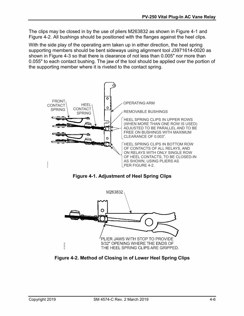
The clips may be closed in by the use of pliers M263832 as shown in Figure 4-1 and Figure 4-2. All bushings should be positioned with the flanges against the heel clips. With the side play of the operating arm taken up in either direction, the heel spring supporting members should be bent sideways using alignment tool J3971614-0020 as shown in Figure 4-3 so that there is clearance of not less than 0.005" nor more than 0.055" to each contact bushing. The jaw of the tool should be applied over the portion of the supporting member where it is riveted to the contact spring.
Figure 4-1. Adjustment of Heel Spring Clips
Figure 4-2. Method of Closing in of Lower Heel Spring Clips
FRONTCONTACT
SPRINGHEEL
CONTACT SPRING
OPERATING ARM
REMOVABLE BUSHINGS
HEEL SPRING CLIPS IN UPPER ROWS(WHEN MORE THAN ONE ROW IS USED)ADJUSTED TO BE PARALLEL TO BEFREE ON BUSHINGS WITH MAXIMUMCLEARANCE OF 0.003”.
AND
HEEL SPRING CLIPS IN BOTTOM ROWOF CONTACTS OF ALL RELAYS, ANDON RELAYS WITH ONLY SINGLE ROWOF HEEL CONTACTS, TO BE CLOSED-INAS SHOWN, USING PLIERS ASPER FIGURE 4-2.
4C5.
0024
.00

PV-250 Vital Plug-In AC Vane Relay
Copyright 2019 SM 4574-C Rev. 2 March 2019 4-7
Figure 4-3. Application of Bending Tools 4.4.4. General Parts Replacement 4.4.4.1. Replacing Contact Block
If the contact block is to be replaced by another, remove the old block, then use a small punch to remove the small dowel pins. Attach the new block with the four screws. Run a #42 drill (0.0935 Dia.) through the dowel pin holes into the epoxy contact block for a total depth of 9/16" + 1/32 - 0.
NOTE
Replacement contact blocks MUST be of the same general design.
Carefully install the dowel pins, tapping in until they are flush with the aluminum surface. If it is necessary to install a used contact block from another relay, remove only one of the dowel pins from the aluminum frame. Carefully press the block on the remaining pin and fasten in place with the screws. One dowel pin will adequately hold the block in place. Install the contact block mounting screws and torque them to 10 ± 2 inch pounds. Do not over-tighten or force parts when reassembling a relay. Upon completion of reassembly, calibrate the relay as directed in paragraph 4.6. 4.5. ADJUSTMENTS All adjustments of contacts should be made by bending the brass support member with the bending tool applied between the rivets that fasten the contact spring to it. Because
3 WAY BENDINGTOOL
N451151-2401
ALIGNMENT TOOLJ397164-0020
4C5.
0026
.00

PV-250 Vital Plug-In AC Vane Relay
Copyright 2019 SM 4574-C Rev. 2 March 2019 4-8
of the effect of the weight of the contact tips, all checks of contact adjustment should be made with the relay in the normal upright position. 4.5.1. Recommended Tools
Gap Gauge - 0.001" to 0.060" Gram Scale - 0 to 30 grams Pliers (Heel Clip) - M263832 Bending Tool - J397164-0020 Bending Tool - N1451151-2401 Adjustable Torque Arm - N171156
4.5.2. Contact Adjustments 4.5.2.1. Initial Contact Adjustment
a. Front and Back Contacts All front and back contact springs should be adjusted to have an initial pressure of 20 grams (10 grams each tip). On the back contact springs, a gram scale applied at the center of the contact tip should just barely move the flexible bronze spring away from the curved stop member. The stop member should be bent if necessary, not the spring, in obtaining this adjustment. In order to make this check on the front contact springs, using the scale, the spring assembly will have to be checked in the inverted position and the pressure should be 18 grams (9 grams each tip), to compensate for the weight of the contact tip. The contact buttons of the bifurcated springs should close at the same instant.
b. Heel Contacts The design of heel contact provides a flexible hinge arrangement with a rigid assembly on the outer part of the member. The thin center spring should be straight and the projection on the upper and lower pressure plates should both bear against the thin center spring. This heel spring assembly should deflect through its full motion with very slight pressure from the operating arm. The heel spring has to be handled carefully in order not to distort the thin center member. The heel springs should be adjusted so that with the relay held with the base horizontal and the contact springs pointing downward the heel spring will take a free position when not connected to the operating arm without appreciable bias either toward the front or back contacts.
4.5.2.2. Final Contact Adjustments
The front and back contact springs should be lined up with their associated heel springs using alignment tool J397164-0020 as explained for the heel contact springs. The normal contact adjustment provides 0.031" compression of the front contacts with the vane just touching the upper roller stop, 0.025" compression of the back contacts when the vane just touches the lower roller stop, and 0.025" opening of the back contacts with the fronts just barely closed. These adjustments can be obtained by using

PV-250 Vital Plug-In AC Vane Relay
Copyright 2019 SM 4574-C Rev. 2 March 2019 4-9
the proper section of 3-way bending tool N451151-21401 applied as shown in Figure 4-3. Set the front contacts to have 0.055" opening with the vane resting against the lower roller stop, then adjust the back contacts so that they have 0.025" opening with the fronts just barely closed. When the vane is up against the upper roller stop, the opening of the back contacts should check approximately 0.055", and as a further check, each front contact spring should have approximately 0.012" opening from its stop spring. When the vane is touching the lower roller stop, each back contact spring should similarly have approximately 0.010" opening from its stop spring. 4.5.3. Counterweight Adjustment The values for vane torque given in Table 4-1 refer to the counterweight torque needed to just balance the vane so that the front contacts just barely close when the relay is in the normal mounted position without current in the windings and the case is tapped lightly. Unless the adjustment of the counterweight nut or the heel contact springs has been changed, or the operating values are not met, this check will not ordinarily have to be made. In general, it is permissible for the torque to be more than the value shown, provided the operating values are correct. A torque arm Figure 4-4, when used, should be slipped on the vane shaft of the relay with the opening of the slot at the bottom, as shown, and held in place by turning the arm which is threaded on the end, until it is tight against the vane shaft. The small weight on the arm should then be moved to give the desired counterweight, and the counterweight nuts on the relay adjusted so that the front contacts of the relay will just make with the torque arm in a horizontal position. This can be most easily determined by tapping the relay case lightly.
Figure 4-4. Adjustable Torque Arm The notches on the arm are spaced so as to provide the counterweights ordinarily used. With the small weight in the notch nearest the vane shaft a counterweight of 100 inch-grains is indicated; in the second notch 125 inch-grains; in further 25 inch-grain steps to 300 inch-grains and 50 inch-grain steps to 600 inch-grains, except an extra notch at 375 inch-grains. Adjust the counterweight nuts on the vane so that a torque as specified in Table 4-1 is required to just close the front contacts. This torque should be measured with the relay

PV-250 Vital Plug-In AC Vane Relay
Copyright 2019 SM 4574-C Rev. 2 March 2019 4-10
in its normal operating position and with all operating arms connected to the heel contacts, using an adjustable torque arm. At least 1/16" clearance should exist between the end of the counterweight screw and the main support casting. The counterweight lock nut shall be securely locked and the end of the screw spread slightly so as to prevent the nuts backing off. 4.6. CALIBRATION 4.6.1. Recommended Test Equipment
Variable autotransformer (Variac) - 115 V @ 1.0 Amp. AC Ammeter AC Voltmeter Resistor - variable, 0-250 ohms, 50 watts SPST Switch
4.6.2. Procedure NOTE
When performing Shop Calibration, set the local voltage as specified to within ± 1%.
Connect the circuit shown in Figure 4-5. a. Set switch Sl to the Off position. b. Set Variac output control to minimum output setting. c. Adjust value of variable resistor R to 250 ohms for the track circuit relay test (or
at full output of Variac, adjust resistor so that the current flowing is 10% above Full-Stroke value).
d. Connect circuit to 115V, ± 1%, AC, 60 Hz line. e. Set switch S1 to the On position. f. Slowly adjust the Variac control to increase the output until the front contacts just
close and note the value indicated on the AC Ammeter. This is the Pick-up value and should be within ± 5%ofthe value specified in Table 4-1.
g. Again, slowly increase the output until the vane just touches the top roller and note the value indicated on the AC ammeter. This is the Full Stroke value and should be within +5% of that specified in Table 4-1.
h. Slowly adjust the Variac control to decrease the output until the front contacts open and note the value indicated on the AC ammeter. This is the Minimum Drop-Away and should not be less than the percentage (specified in Table 4-1) of actual pick-up value measured in Step f.

PV-250 Vital Plug-In AC Vane Relay
Copyright 2019 SM 4574-C Rev. 2 March 2019 4-11
Figure 4-5. AC Vane Relay Test Circuit
115 VAC60 Hz
(ISOLATEDLINE)
ON OFF
S1
T1 R
A
V
C2- C1+
L- L+
RELAYUNDERTEST4C
5.00
30.0
0

PV-250 Vital Plug-In AC Vane Relay
Copyright 2019 SM 4574-C Rev. 2 March 2019 4-12
Table 4-1. Test Operating Values
Torque Inch-
Grams
Nominal Pick-Up Nominal Full Stroke Minimum Drop-
Away & of Actual Pick-Up
Volts Amps Volts Amps Shop Field
400 0.79 0.315 0.925 0.37 90 80
The above values are 13% higher than ideal and apply to test from single phase supply with resistance in series with track winding. Calibration for current values is preferable.
Table 4-2. Operating Values at Ideal Phase Relations
Nominal Pick-Up
Nominal Full Stroke
Minimum Drop-Away % of Actual Pick-Up
Volts Amps Volts Amps
0.70 0.28 0.82 0.327 90
The above values are based on ideal phase relations, track volts lead line volts 90° and track amperes lead line volts 24°. 4.7. CALIBRATION REQUIREMENTS 4.7.1. Test for Balanced Magnetic Circuit With the relay standing on its back so that the vane hangs down with front and back contacts open, apply normal voltage and frequency to the local winding. There should not be any appreciable movement of the vane, particularly no tendency to close the front contacts. 4.7.2. In-Service Test Calibration requirements will be met when the relay calibration values are the same as those given in Table 4-1 of this manual. After any shop adjustments are made, check the calibration values (paragraph 4.6) and if they are not within the values given in Table 4-1 of this manual the relay should not be placed in service.

PV-250 Vital Plug-In AC Vane Relay
Copyright 2019 SM 4574-C Rev. 2 March 2019 4-13
4.7.3. Contact Resistance Resistance of front contacts should be measured with the armature in its full-stroke position, and resistance of back contacts should be measured with the armature fully released. Cleaned contact resistance should not exceed the following values.
Type of Contacts Front Contacts Back Contacts Silver-to-Silver Impregnated Carbon 0.09 0.18 Silver-to-Silver ---- 0.03
Contact surfaces should not be disturbed unless there is evidence of severe pitting from excessive loading or an accidental short through the contacts. When contacts must be dressed, refer to paragraph 4.2.1 or 4.2.2.

PV-250 Vital Plug-In AC Vane Relay
Copyright 2019 SM 4574-C Rev. 2 March 2019 4-14

PV-250 Vital Plug-In AC Vane Relay
Copyright 2019 SM 4574-C Rev. 2 March 2019 A-1
APPENDIX-A. PARTS LIST
PARTS LIST FOR PV-250 RELAYS (N3142555-003; -803; -903)
(See Figure A-1) ITEM DESCRIPTION PART NUMBER
1 Relay Frame M376046 2 Rod, Latch M375913 3 Knob, Round, Knurled, 6-32, 5/8" Dia. J770536 4 Nut, 1/8 Hvy. M395496 5 Latch, Machined M321728 6 Pin, Roll Sst. J048716 7 Spring, Plated M321861 8 Pin Roll Elastic Stop Nut J487087 9 Screw, 8-32 x 7/16" L J5220402-001 10 Bottom Cover (Used On -003, -903) J776304-0001 10 Bottom Cover (Used On -803) J776597 11 Screw, 8-32 x 7/16 Fil. Hd. SS. J522042 12 Gasket, Rubber J047081 13 Screw, #8-32 x ¼ Rd. Stl. T. Pl. J052639 14 Handle, Pull Aluminum J561111 15 Washer, #10, Int. Tooth Ph. Bz. N. Pl. J047710 16 Screw, #10-32 x 3/8 Pan. Hd. J525277 17 Calibration TAG S002036 17A Adhesive Film 791665 18 Wire-Seal, #22 AWG, 2 Ply A043013 19 Seal-Security, Gray J079351 20 Plate, Name M437859 21 Screw, #4-40 x 3/16, Rd. Stl. (F) Tp J525024 22 Bracket, Support M375890 23 Screw, #10-32 X ½" Fl. Stl. Tp J052091 24 Field Control N251093 25 Field Local N251094 26 Vane N386457 27 Screw, Trunnion N124889 28 Bushing M232934 29 Bushing M283459 30 Roller M069693 31 Bracket Upper Roller M397483 32 Bracket Lower Roller M161753 33 Plate Clip M090506 34 Bracket, Lock M109074 35 Rivet, #10 X 5/16" Rd. Ph. Bz. J049813 36 Pin M381128 37 Washer, Tension T.P. J047714 38 Pin M381129 39 Pin M232031 40 Pin M232935 41 Block, Terminal (Used On -803, -903) M433457 41 Block, Terminal (Used -003) M386480 42 SCREW, 8-32 x 7/16 Rd. Hd. St. J725106 43 Pin, Indexing Elastic Stop Nut J487090 44 Parts Bag N349711-5503 45 Block Contact, See Note A N386455-0001 46 Block Contact, See Note A N386456-0001

PV-250 Vital Plug-In AC Vane Relay
Copyright 2019 SM 4574-C Rev. 2 March 2019 A-2
ITEM DESCRIPTION PART NUMBER 47 Screw, 8-32 x 7/8" Rd. Hd. Stl. Tp. J7052603 48 Arm, Operating N390324 49 Counterweight M451175-0302 50 Counterweight, Locknut M029956 51 Top Cover/Testing Device (Used On -003) N384546 51 Top Cover, Lexan (Used On -803, -903) J776598 Screw #6-32 X ¼" Fil. Hd. J052485 Washer Arc. Spr. Std. J475114 Term. Pre. Insul. Dia. G J730077 NOTE A
When reordering contact blocks, be sure to include the "-0001" suffix with the part number. This assures proper processing of the contacts for optimum performance in these relays.

PV-250 Vital Plug-In AC Vane Relay
Copyright 2019 SM 4574-C Rev. 2 March 2019 A-3
Figure A-1. PV-250 Relay Assembly
PARTS LIST FOR VANE (N386457)

PV-250 Vital Plug-In AC Vane Relay
Copyright 2019 SM 4574-C Rev. 2 March 2019 A-4
(See Figure A-2) ITEM DESCRIPTION PART NUMBER
1 Vane Crank N387970 2 Vane M231734 3 Clips Buffer M130658 4 Rivets #19 x 5/16 Rd. Hd. Ph. Bz. J049804 5 Washer M091997 6 Rivets #11 x 5/16 Rd. Hd. Ph. Bz. J049812
Figure A-2. Vane Assembly

PV-250 Vital Plug-In AC Vane Relay
Copyright 2019 SM 4574-C Rev. 2 March 2019 A-5
PARTS LIST FOR OLD STYLE MOUNTING BASE (N3861458) (See Figure A-3)
ITEM DESCRIPTION PART NUMBER 1 Mounting Base Complete – See Note B M386458 2 Mounting Base Only N386458-009 3 Tag J075828 4 Contact Receptacle Solderless #10 to #12 Wire J680181 4 Contact Receptacle Solderless #14 to #16 Wire J680165 4 Contact Receptacle Solderless #18 to #20 Wire J680179 5 Meter Test Plug M322965
6 Insulated test Plug (For operating any coil or contact circuits and for removing receptacle springs) J077931
NOTE B When mounting base complete is ordered, a plastic bag 4-1/8" x 5-1/2" of parts is included in the inner carton with the mounting base and instruction prints.
Bag Contains:
(Req'd. Quantity)
(2) tags (4) #4-40 x 3/16" rd. hd. Screws (4) ¼" Steel Plate Washers
* (4) ¼" -20 x 1-1/4" Rd. Hd. Stl. Screws * (4) Washers * (4) ¼" Steel Lock Washers * (4) 1/$ -20 Steel Hex Nuts
And
Contact receptacles (solderless J680165 for #14 to #16 wire. If other wire size is used, request the proper part number as shown in Item 4 when ordering base complete. (i.e. N386458 except using contact receptacles, solderlessJ6801801.
Asterisk (*) items are for attaching mounting base to the rack.

PV-250 Vital Plug-In AC Vane Relay
Copyright 2019 SM 4574-C Rev. 2 March 2019 A-6
Figure A-3. Old Style Mounting Base PARTS LIST FOR NEW IMPROVED MOUNTING BASE (N438689-003)
APP
LY R
ECEP
TAC
LE S
PRIN
GS
LO
CK
ING
SID
E D
OW
N
7-15/16
7-5/16
4-15
/16
19/3
25/
162-
1/2
1-27
/32
3-3/
4
5/16
1-27
/32
2-1/
219
/32
3
3
2
56
4
4C5.0104.00

PV-250 Vital Plug-In AC Vane Relay
Copyright 2019 SM 4574-C Rev. 2 March 2019 A-7
(See Figure A-4) ITEM DESCRIPTION PART NUMBER
1 Base Only J780054 2 Strike J792848 3 Nut J480280 4 Receptacle Contact Spring, Solderless #10 to #12 Wire M451142-2703 4 Receptacle Contact Spring, #14 to #16 Wire M451142-2702 4 Receptacle Contact Spring, #18 to #20 Wire M451142-2701 5 Tag J705951 6 Screw, ¼-20 x 1-1/4 Rd. Hd. J052667 Lock Washer ,1/4 Stl. J047775 Plate Washer ,1/4 Stl. J047501 Nut ¼-20. Hex. Stl. J048002 NOTE B
When mounting base complete is ordered, a bag of parts is included that contains:
(2) Tags (Item 5) *(4) Screws (Item 6) *(4) Lock Washers (Item7) *(4) Plate Washers (Item 8) *(4) Nuts (Item 9)
And (Req'd. Quantity) Receptacles contact springs (M451142-2702 for #14 to #16 wire. If other wire size is needed, request the proper part number as shown in Item 4 when ordering base complete. (i.e. N438689-003 except using contact receptacle contact springs, solderless M451142-2703.)
(*) These items are for attaching mounting base to the rack.

PV-250 Vital Plug-In AC Vane Relay
Copyright 2019 SM 4574-C Rev. 2 March 2019 A-8
Figure A-4. Improved Mounting Base
VIEW
"A"
LOC
KIN
G S
IDE
OF
STR
IKE
APP
LY R
EC
EPTA
CLE
SPR
ING
S L
OC
KIN
G S
IDE
DO
WN
FRO
NT
7-15/16
7-5/16
LOC
KIN
G S
IDE
OF
STR
IKE
4-15
/16
19/3
22-
1/2
1-27
/32
3-3/
4
5/165/161-
27/3
22-
1/2
19/3
2
5
4
4C5.0023.00
2
1
2
67
89
3 5

PV-250 Vital Plug-In AC Vane Relay
Copyright 2019 SM 4574-C Rev. 2 March 2019 A-9

PV-250 Vital Plug-In AC Vane Relay
Copyright 2019 SM 4574-C Rev. 2 March 2019 A-10
End of Manual