Putting 40/100GbE to the Test - Spirent Communications
36
A Light Reading Webinar Putting 40/100G To The Test Wednesday, October 28, 2009 Hosted by Andy Bray Independent Analyst Sponsored by:
Transcript of Putting 40/100GbE to the Test - Spirent Communications
A Light Reading Webinar
Putting 40/100G To The Test
Wednesday, October 28, 2009
Hosted by
Andy Bray Independent Analyst
Sponsored by:
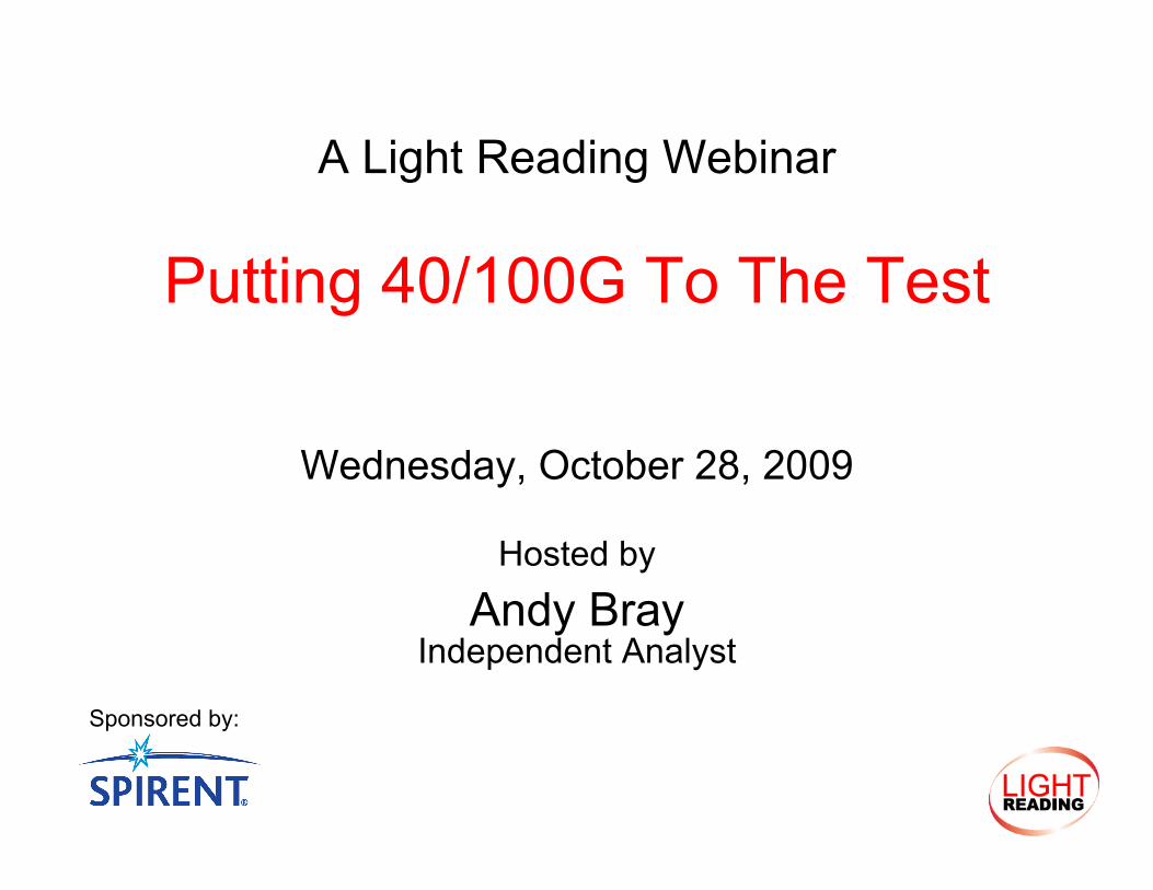
Spirent Communication is a…. • Global test vendor with solutions for the lab and
into live networks • Next Generation Technology coverage from Data
Centers, Virtualization, 3G/4G Wireless Technologies, Mobile Backhaul, Satellite/Positioning and 40/100G Ethernet
Michael Lynge • Ethernet Testing Evangelist • Data Communications Test Industry for over 15
years • Over the last 9 years at Spirent, has been the
Product Manager of SmartBits, AX/4000, Avalanche and Spirent TestCenter products families
About Spirent Communications
http://www.spirent.com
• One company (3Com) - Three Brands • $1.3B networking specialist • H3C high-end networking brand launched in May 2009 • #2 in global enterprise switch (ports) and routers (units) market share • #1 in China, securing over 30% of the Fortune 1000
• David Law • Engineering Consultant at 3Com / H3C • Specification, development of Ethernet products since 1989 • IEEE 802.3 Ethernet Working Group • Editor for the IEEE 802.3u 100BASE-T Repeater Sub Task Force, • Chair of the IEEE 802.3z 1Gb/s Ethernet Mgt Sub Task Force • Editor of the IEEE 802.3ae 10Gb/s Ethernet Mgt Sub Task Force • Vice-Chair of the IEEE 802.3 Ethernet Working Group from 1996 until 2008
• Presently the Chair of the IEEE 802.3 Ethernet Working Group
About H3C http://www.h3cnetworks.com
• Market • 40/100G Ethernet Basics • How It Works • Validating That It Works • Summary • Q&A
Agenda

Market
40/100G Drivers
• Computing • Driven by key technologies
• Internal bus and memory performance • System throughput doubles approximately every 2 yrs
• Core networking • Driven by cumulative effect of more users, bandwidth, applications • Wide area, ISPs, IXs
• Increase number of users • Increase in bandwidth available
• xDSL, xPON, Cable, 3G • Increase number of applications
• YouTube, Facebook, Netflix • Enterprise
• Aggregation of multiple computing systems • Core throughput doubles approximately every 18 months
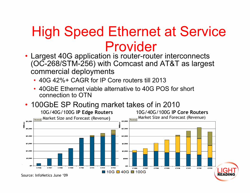
High Speed Ethernet at Service Provider
• Largest 40G application is router-router interconnects (OC-268/STM-256) with Comcast and AT&T as largest commercial deployments • 40G 42%+ CAGR for IP Core routers till 2013 • 40GbE Ethernet viable alternative to 40G POS for short
connection to OTN • 100GbE SP Routing market takes of in 2010
10G/40G/100G IP Edge Routers Market Size and Forecast (Revenue)
10G/40G/100G IP Core Routers Market Size and Forecast (Revenue)
Source: InfoNetics June ‘09
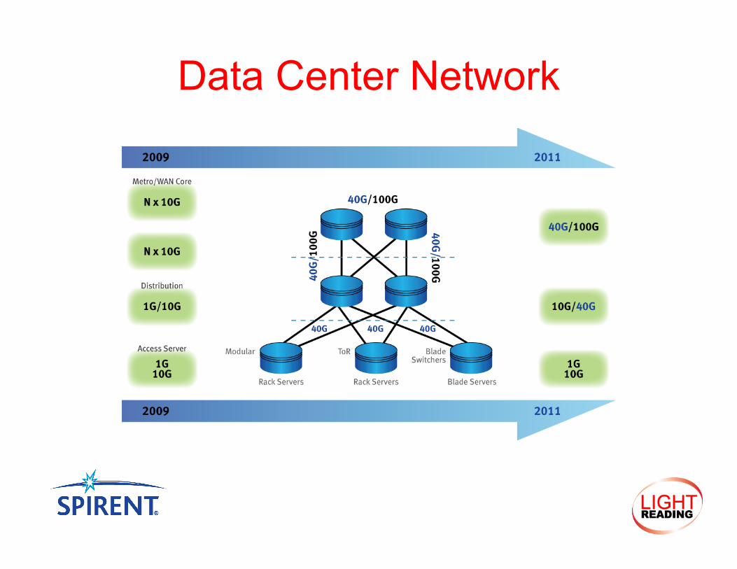
Data Center Network
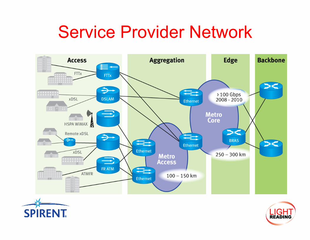
Service Provider Network

Validation
• Each element has to be characterized and then the system as whole
• Different Types of Test • Conformance • Functional • Performance
• Different Levels of Focus
Device System Data plane End-to-end capability Control plane Network Impairment Backplane Convergence Times
Prioritization Resiliency
But first we need to understand the technology
IEEE P802.3ba 40/100G Ethernet Basics
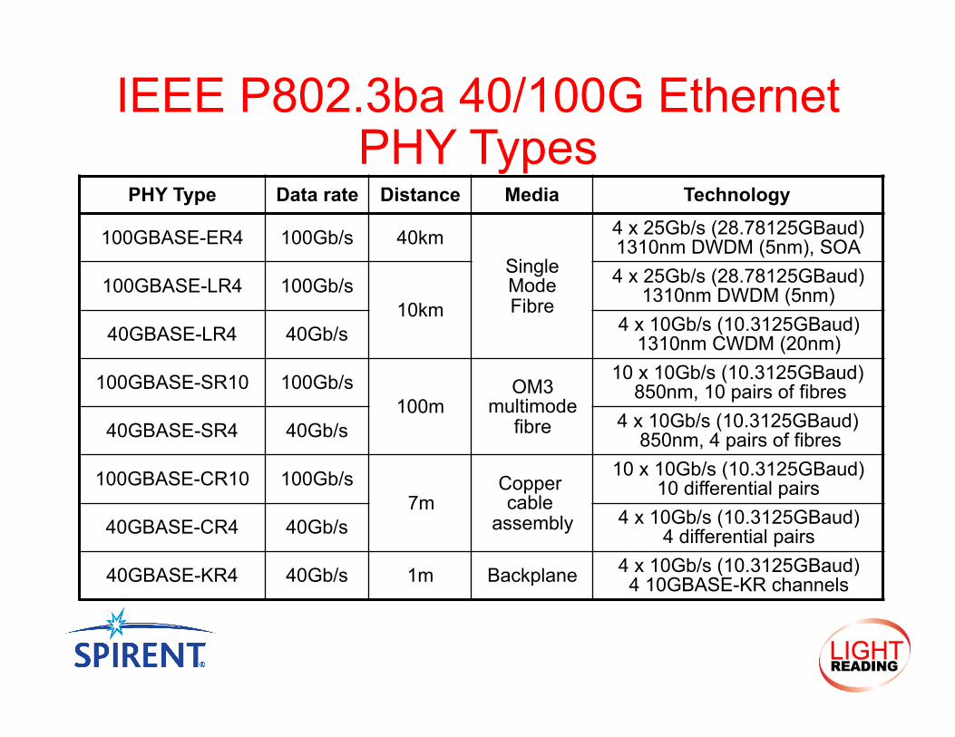
IEEE P802.3ba 40/100G Ethernet PHY Types
PHY Type Data rate Distance Media Technology
100GBASE-ER4 100Gb/s 40km Single Mode Fibre
4 x 25Gb/s (28.78125GBaud) 1310nm DWDM (5nm), SOA
100GBASE-LR4 100Gb/s 10km
4 x 25Gb/s (28.78125GBaud) 1310nm DWDM (5nm)
40GBASE-LR4 40Gb/s 4 x 10Gb/s (10.3125GBaud) 1310nm CWDM (20nm)
100GBASE-SR10 100Gb/s 100m
OM3 multimode
fibre
10 x 10Gb/s (10.3125GBaud) 850nm, 10 pairs of fibres
40GBASE-SR4 40Gb/s 4 x 10Gb/s (10.3125GBaud) 850nm, 4 pairs of fibres
100GBASE-CR10 100Gb/s 7m
Copper cable
assembly
10 x 10Gb/s (10.3125GBaud) 10 differential pairs
40GBASE-CR4 40Gb/s 4 x 10Gb/s (10.3125GBaud) 4 differential pairs
40GBASE-KR4 40Gb/s 1m Backplane 4 x 10Gb/s (10.3125GBaud) 4 10GBASE-KR channels
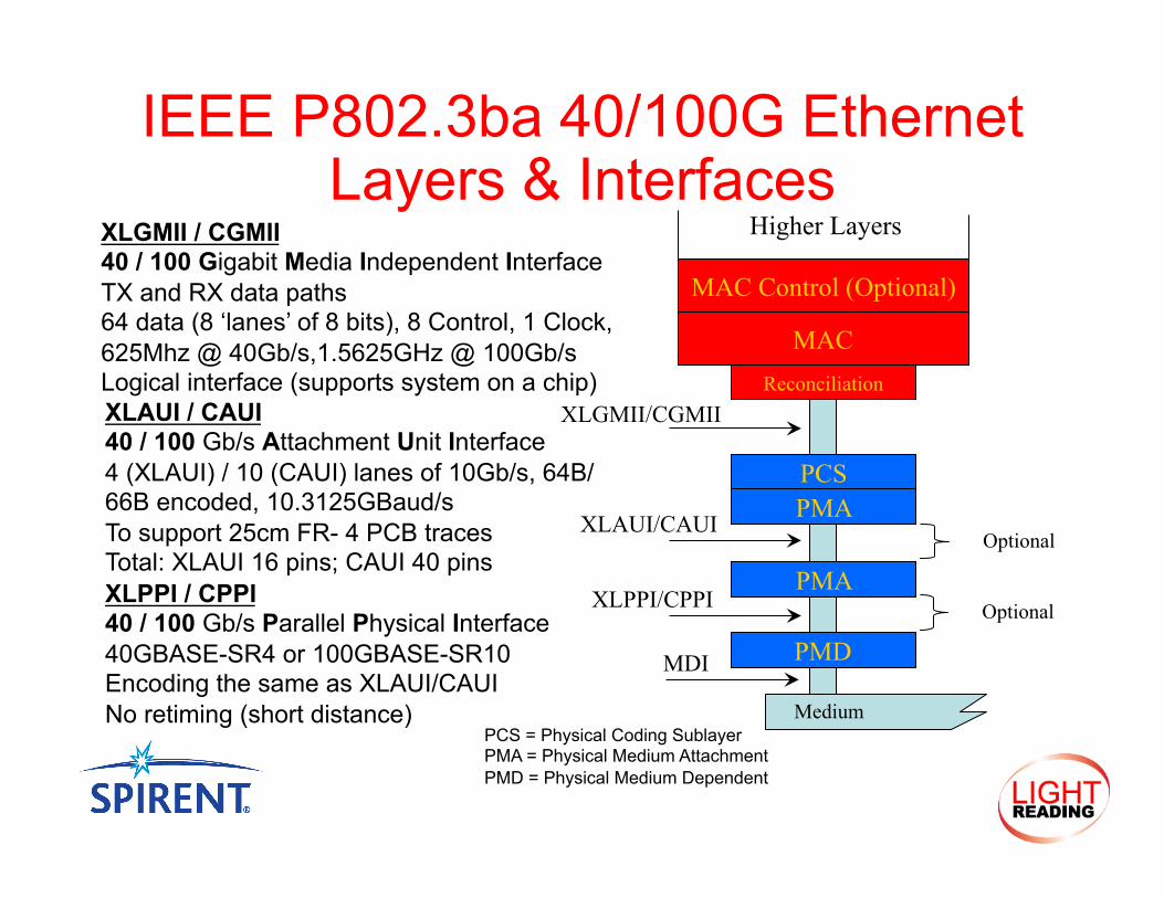
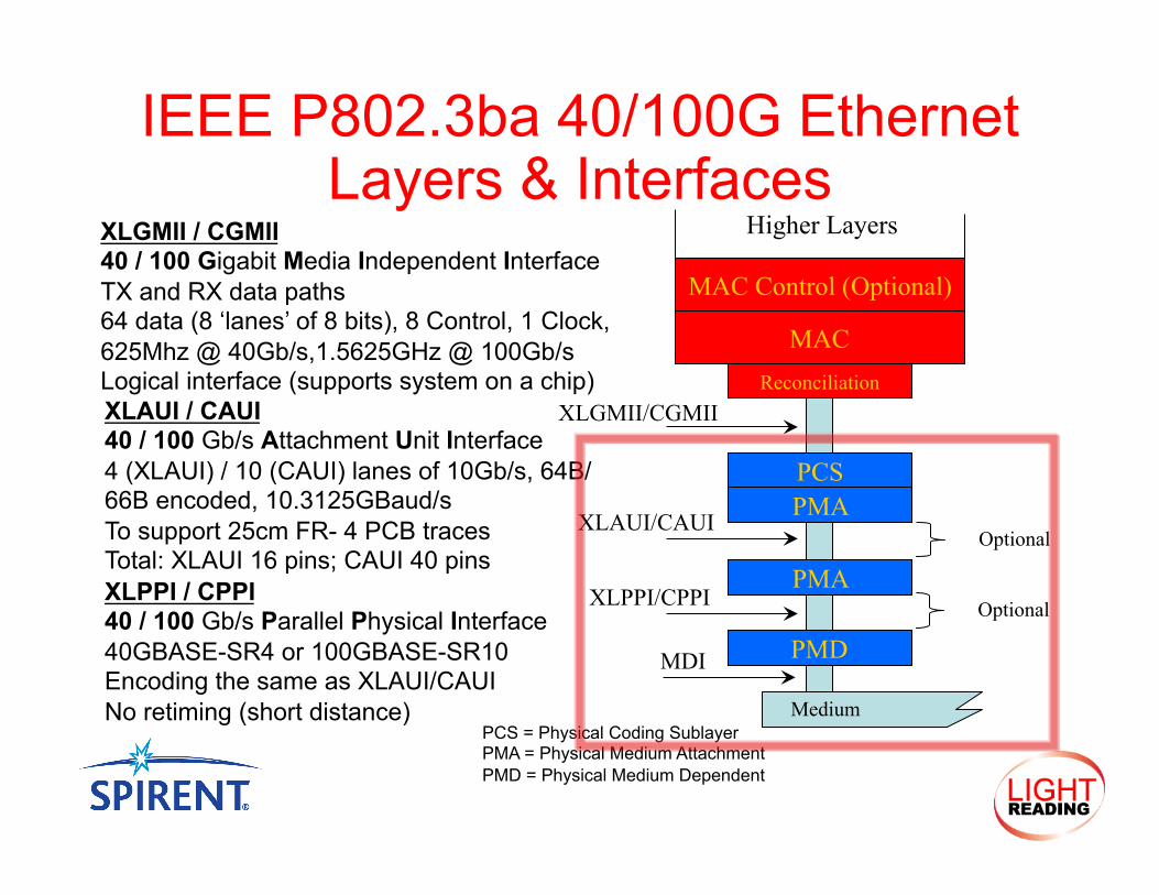
IEEE P802.3ba 40/100G Ethernet Layers & Interfaces
PCS PMA
PMD
PMA
Reconciliation
MAC
MAC Control (Optional)
Higher Layers
Optional
XLGMII / CGMII 40 / 100 Gigabit Media Independent Interface TX and RX data paths 64 data (8 ‘lanes’ of 8 bits), 8 Control, 1 Clock, 625Mhz @ 40Gb/s,1.5625GHz @ 100Gb/s Logical interface (supports system on a chip)
Medium
XLGMII/CGMII
XLAUI/CAUI
XLAUI / CAUI 40 / 100 Gb/s Attachment Unit Interface 4 (XLAUI) / 10 (CAUI) lanes of 10Gb/s, 64B/66B encoded, 10.3125GBaud/s To support 25cm FR- 4 PCB traces Total: XLAUI 16 pins; CAUI 40 pins
PCS = Physical Coding Sublayer PMA = Physical Medium Attachment PMD = Physical Medium Dependent
XLPPI/CPPI XLPPI / CPPI 40 / 100 Gb/s Parallel Physical Interface 40GBASE-SR4 or 100GBASE-SR10 Encoding the same as XLAUI/CAUI No retiming (short distance)
Optional
MDI
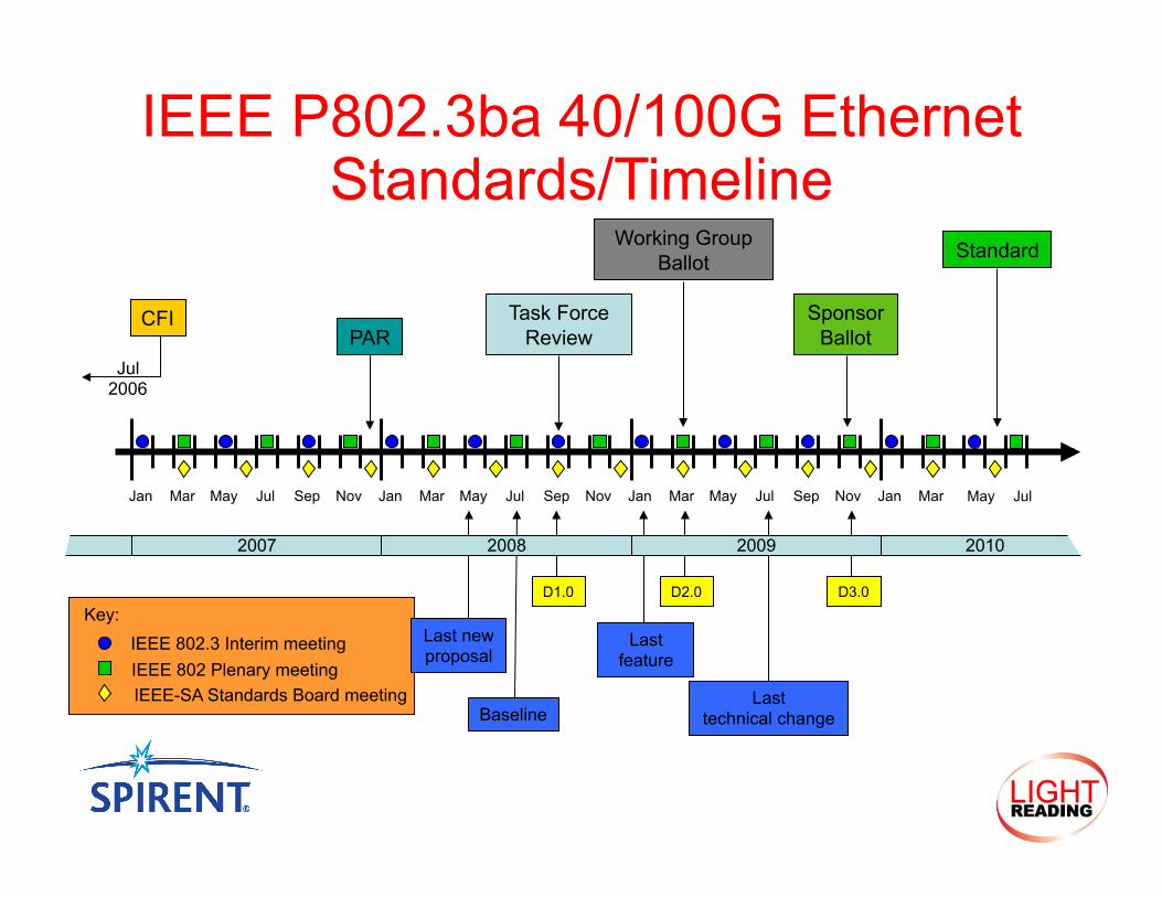
IEEE P802.3ba 40/100G Ethernet Standards/Timeline
D2.0
Jan Mar May Jul Sep Nov Jan Mar May Jul Sep Nov Jan Mar May Jul Sep Nov Jan
IEEE 802.3 Interim meeting IEEE 802 Plenary meeting IEEE-SA Standards Board meeting
Key:
Mar
CFI PAR
Task Force Review
Working Group Ballot
Sponsor Ballot
Standard
Last new proposal
2007 2008 2009 2010
Last feature
Last technical change Baseline
D1.0 D3.0
May Jul
Jul 2006
What timeframe do you think 40/100G Ethernet will start to be adopted or deployed? • Pre standard (2009-mid 2010) • Late 2010 • Early 2011 • After mid to late 2011 • Even later still
Poll Question #1
How It Works
IEEE P802.3ba 40/100G Ethernet Layers & Interfaces
PCS PMA
PMD
PMA
Reconciliation
MAC
MAC Control (Optional)
Higher Layers
Optional
XLGMII / CGMII 40 / 100 Gigabit Media Independent Interface TX and RX data paths 64 data (8 ‘lanes’ of 8 bits), 8 Control, 1 Clock, 625Mhz @ 40Gb/s,1.5625GHz @ 100Gb/s Logical interface (supports system on a chip)
Medium
XLGMII/CGMII
XLAUI/CAUI
XLAUI / CAUI 40 / 100 Gb/s Attachment Unit Interface 4 (XLAUI) / 10 (CAUI) lanes of 10Gb/s, 64B/66B encoded, 10.3125GBaud/s To support 25cm FR- 4 PCB traces Total: XLAUI 16 pins; CAUI 40 pins
PCS = Physical Coding Sublayer PMA = Physical Medium Attachment PMD = Physical Medium Dependent
XLPPI/CPPI XLPPI / CPPI 40 / 100 Gb/s Parallel Physical Interface 40GBASE-SR4 or 100GBASE-SR10 Encoding the same as XLAUI/CAUI No retiming (short distance)
Optional
MDI
• Serial 40Gb/s Ethernet support some way off • Not included in initial 40Gb/s PHY set • Work on project proposal starts at November 2009 meeting
• Serial 100Gb/s Ethernet operation further in the future • Technology demonstrations just taking place
• IEEE P802.3ba PHYs therefore lane based • Encoding termed Multi-Lane Distribution (MLD) • Logical lanes called PCS lanes (PCSL)
• IEEE P802.3ba PCS designed to support future PHYs • Don’t want a new PHY to require a new PCS • This is what happened for some of the 10Gb/s PHYs
IEEE P802.3ba 40/100G Ethernet Physical Coding Sublayer (PCS)
• Based on 10GBASE-R 64B/66B PCS • Data striped round robin across lanes 66 bit blocks at a time • Periodic alignment blocks are added to allow deskew
• Allows random ordering of lanes across link • Rate of marker insertion low, every 16383 blocks
• Accommodated in normal IPG • Support multiple PCSL widths with the same PCS layer
• PMA maps n lane interface to m lane interface • PMA is simple bit level muxing
• Does not know or care about PCS coding • Alignment performed at RX PCS • Compensation for ‘fixed’ skew performing at RX PCS
• Compensation for ‘dynamic’ skew performed at each sublayer
Multi-Lane Distribution (MLD)
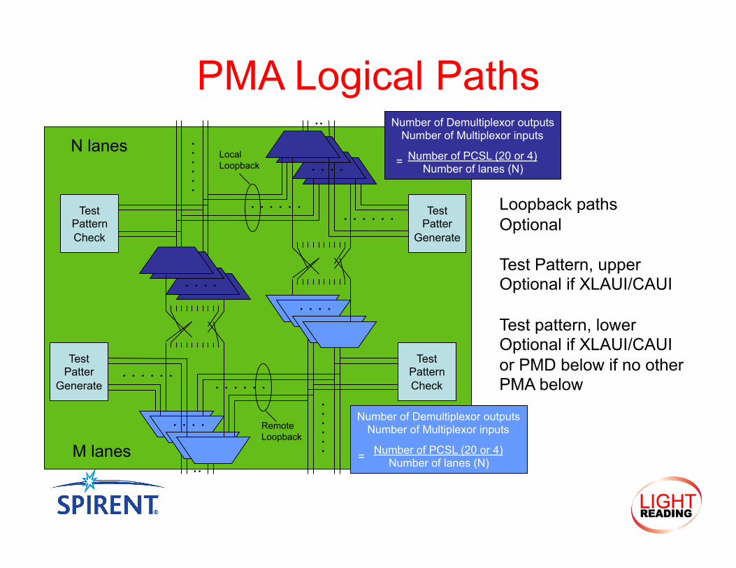
PMA Logical Paths
M lanes
Number of Demultiplexor outputs Number of Multiplexor inputs
Number of PCSL (20 or 4) Number of lanes (N)
=
Test Patter
Generate . . . . . .
. . . .
. . . . . .
. . . .
. . . . . .
Test Pattern Check
Remote Loopback
..
Test Patter
Generate
. . . . . .
. . . .
. . . . . .
. . . .
. . .
. . .
Test
Pattern Check
Local Loopback
..
N lanes
Number of Demultiplexor outputs Number of Multiplexor inputs
Number of PCSL (20 or 4) Number of lanes (N) =
Loopback paths Optional
Test Pattern, upper Optional if XLAUI/CAUI
Test pattern, lower Optional if XLAUI/CAUI or PMD below if no other PMA below
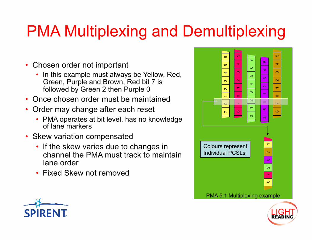
PMA Multiplexing and Demultiplexing
• Chosen order not important • In this example must always be Yellow, Red,
Green, Purple and Brown, Red bit 7 is followed by Green 2 then Purple 0
• Once chosen order must be maintained • Order may change after each reset
• PMA operates at bit level, has no knowledge of lane markers
• Skew variation compensated • If the skew varies due to changes in
channel the PMA must track to maintain lane order
• Fixed Skew not removed
3 2
1 0
5 4 3
2 1
0 5
4
3 2
1 0
5 4
3 2
1 0
5 4
6 7
7 6
6 7
5 4
3 2
1 0
5 4
7 6
0 7
2 0
7 1 Colours represent
Individual PCSLs
PMA 5:1 Multiplexing example
Are you planning on implementing 40G or 100G Ethernet?
• 40G • 100G • 40G and 100G • No plans
Poll Question #2

Validating That It Works
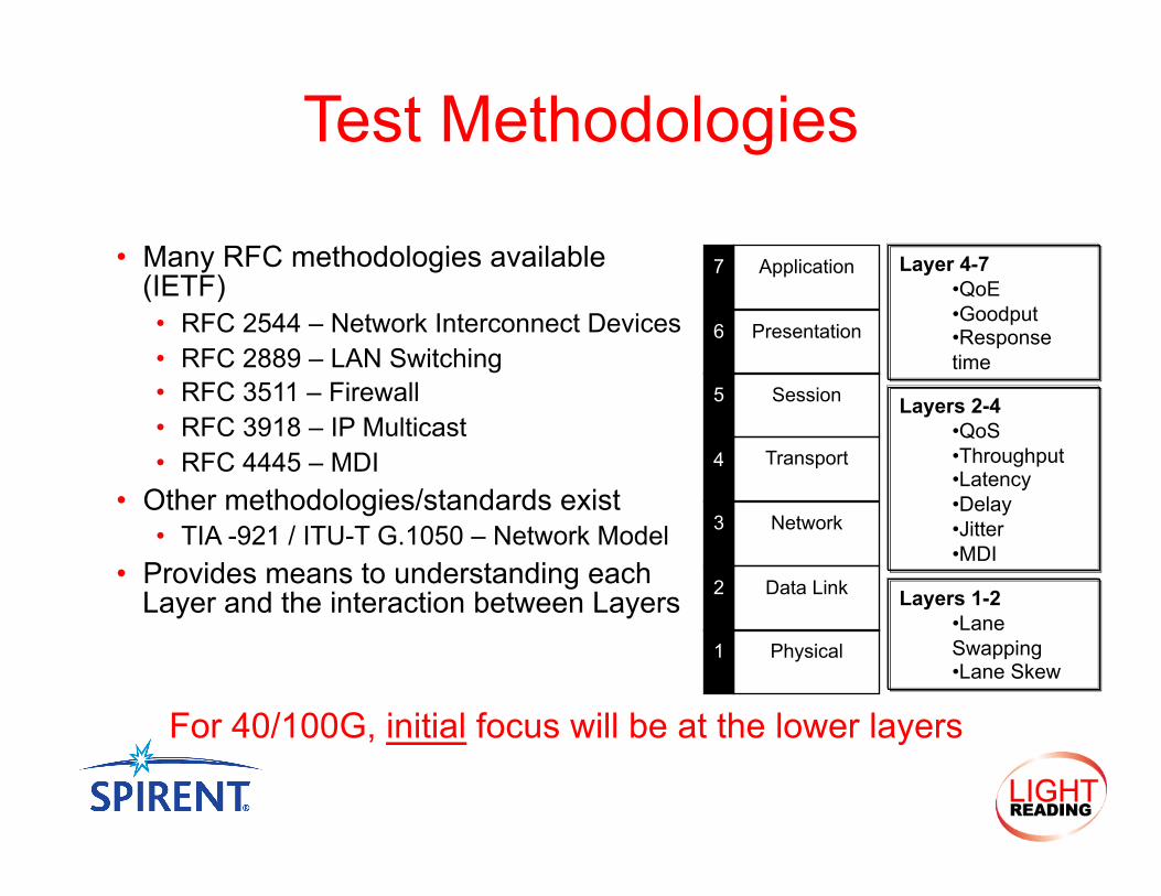
• Many RFC methodologies available (IETF) • RFC 2544 – Network Interconnect Devices • RFC 2889 – LAN Switching • RFC 3511 – Firewall • RFC 3918 – IP Multicast • RFC 4445 – MDI
• Other methodologies/standards exist • TIA -921 / ITU-T G.1050 – Network Model
• Provides means to understanding each Layer and the interaction between Layers
Test Methodologies
Layers 1-2 • Lane Swapping • Lane Skew
Layers 2-4 • QoS • Throughput • Latency • Delay • Jitter • MDI
Layer 4-7 • QoE • Goodput • Response time
Physical
Data Link
Network
Transport
Session
Presentation
Application
1
2
3
4
5
6
7
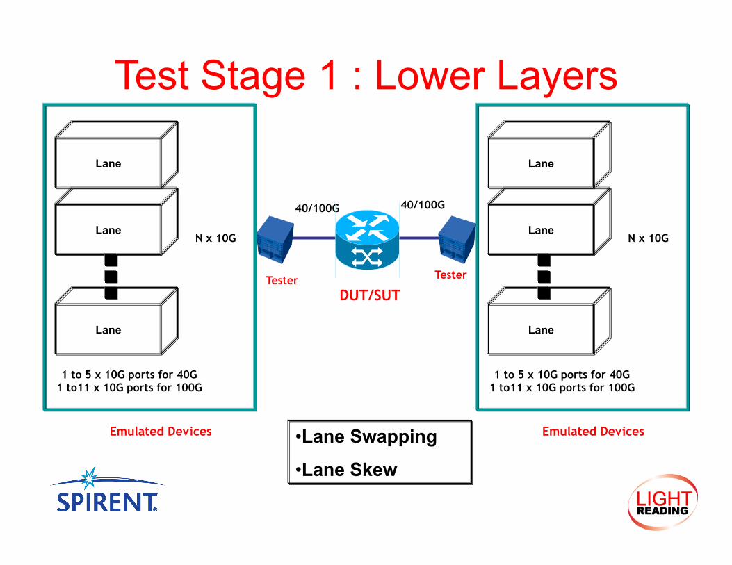
For 40/100G, initial focus will be at the lower layers
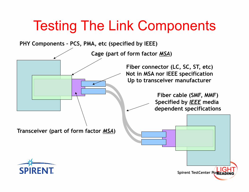
Spirent TestCenter Port
Cage (part of form factor MSA)
Transceiver (part of form factor MSA)
Fiber connector (LC, SC, ST, etc) Not in MSA nor IEEE specification Up to transceiver manufacturer
Fiber cable (SMF, MMF) Specified by IEEE media dependent specifications
PHY Components – PCS, PMA, etc (specified by IEEE)
Testing The Link Components
40/100G 40/100G
Test Stage 1 : Lower Layers
• Lane Swapping
• Lane Skew
DUT/SUT Tester Tester
Emulated Devices Emulated Devices
1 to 5 x 10G ports for 40G 1 to11 x 10G ports for 100G
N x 10G Lane
Lane
Lane
1 to 5 x 10G ports for 40G 1 to11 x 10G ports for 100G
N x 10G Lane
Lane
Lane
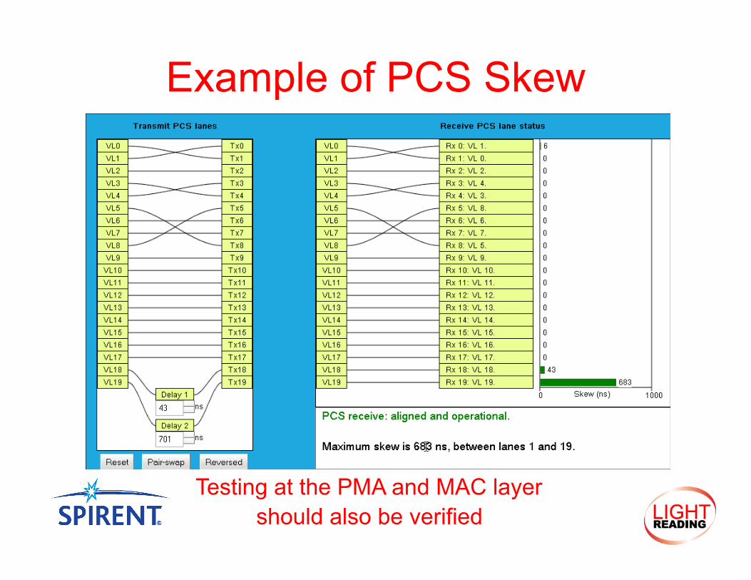
Example of PCS Skew
Testing at the PMA and MAC layer should also be verified
40/100G 40/100G
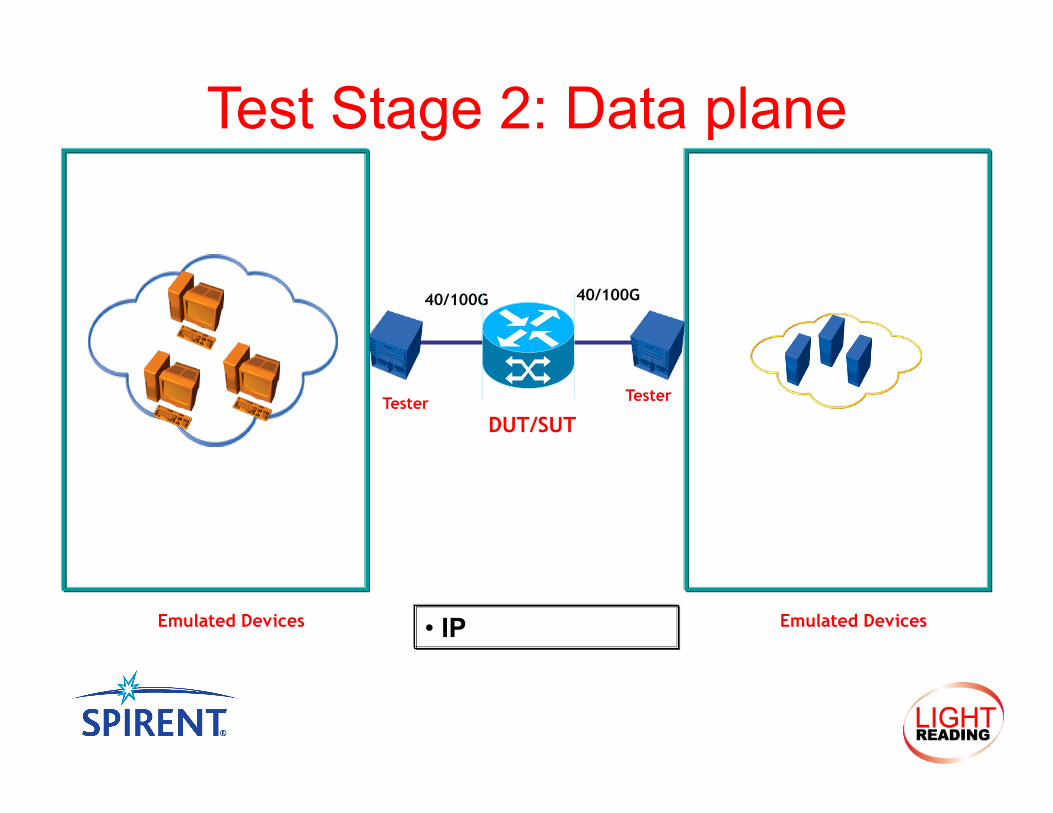
Test Stage 2: Data plane
• IP
DUT/SUT Tester Tester
Emulated Devices Emulated Devices
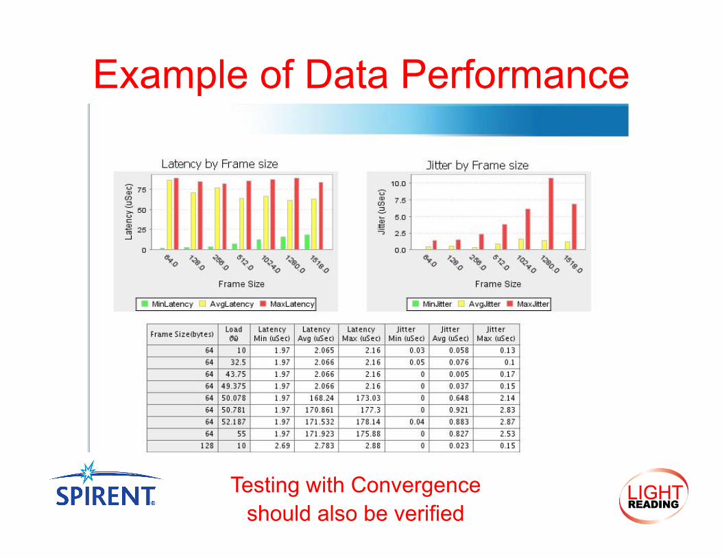
Example of Data Performance
Testing with Convergence should also be verified
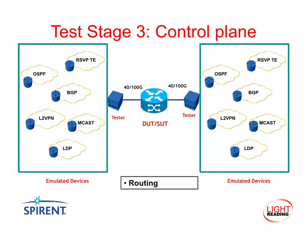
40/100G 40/100G
Test Stage 3: Control plane
• Routing
DUT/SUT Tester Tester
Emulated Devices
OSPF
RSVP TE
BGP
L2VPN MCAST
LDP
Emulated Devices
OSPF
RSVP TE
BGP
L2VPN MCAST
LDP
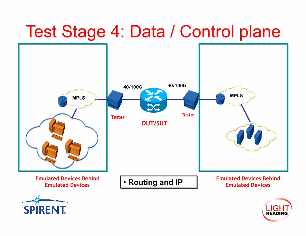
40/100G 40/100G
Test Stage 4: Data / Control plane
• Routing and IP
DUT/SUT Tester Tester
Emulated Devices Behind Emulated Devices
MPLS
Emulated Devices Behind Emulated Devices
MPLS
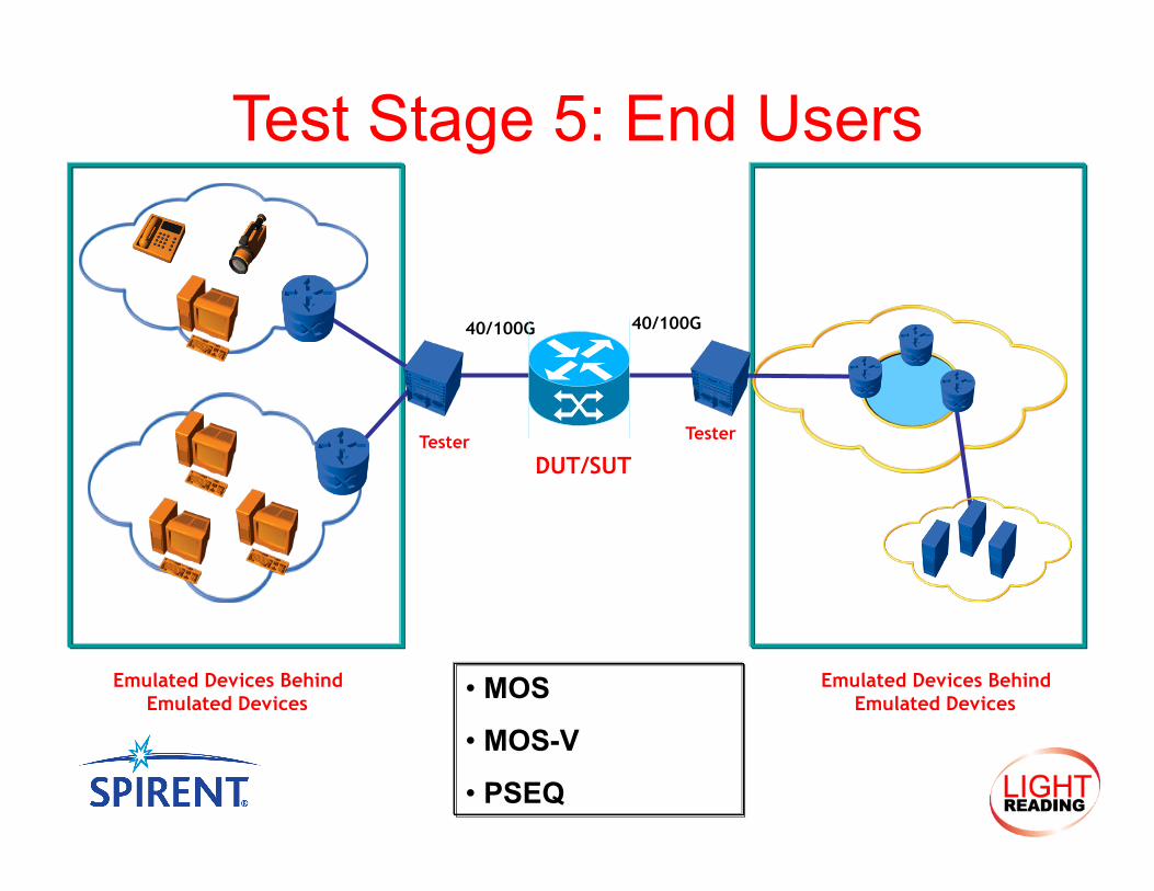
40/100G 40/100G
Test Stage 5: End Users
• MOS
• MOS-V
• PSEQ
DUT/SUT Tester Tester
Emulated Devices Behind Emulated Devices
Emulated Devices Behind Emulated Devices
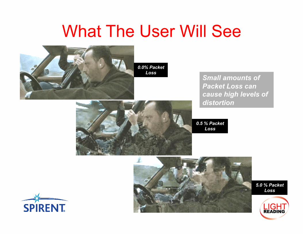
What The User Will See
0.0% Packet Loss
0.5 % Packet Loss
5.0 % Packet Loss
Small amounts of Packet Loss can cause high levels of distortion
What equipment in the network will your organization probably invest in first for 40/100G support?
• Top-of-rack • Edge Routers • Core Routers • Other
Poll Question #3
• 40/100G is the next major advancement for Ethernet offering large amount of bandwidth
• Creates new challenges on multiple levels • Lower layers are the first hurtle • Upper layer will be next
• End goal is improving services such as Video • Validate that the system is ready
Summary
Q&A
www.spirent.com www.h3cnetworks.com