Put your final answers on this sheet and attach any...
5
EE 230 Name__________________________________________ Exam 2 – Nov. 5, 2015 Put your final answers on this sheet and attach any additional sheets behind. You must include your work to get full credit. Problem 1 A comparator transfer characteristic is shown at right. Sketch a circuit that would produce this characteristic. Be sure to specify the details of your circuit: V REF , R a , R b , and the output saturation levels. Note: There are many possible values of R a and R b , but the ratio R a /R b is specific. R a = ____________________ R b = ___________________ V REF = ____________________ V L+ = _________________________ V L– = __________________________ –8 V +8 V +6 V +2 V v i v o
Transcript of Put your final answers on this sheet and attach any...
EE 230 Name__________________________________________Exam 2 – Nov. 5, 2015
Put your final answers on this sheet and attach any additional sheets behind. You must include your work to get full credit.
Problem 1
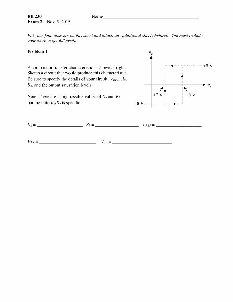
A comparator transfer characteristic is shown at right. Sketch a circuit that would produce this characteristic. Be sure to specify the details of your circuit: VREF, Ra, Rb, and the output saturation levels. Note: There are many possible values of Ra and Rb, but the ratio Ra/Rb is specific.
Ra = ____________________ Rb = ___________________ VREF = ____________________VL+ = _________________________ VL– = __________________________
–8 V
+8 V
+6 V+2 V
vi
vo

EE 230 Name__________________________________________Exam 2 – Nov. 5, 2015
Put your final answers on this sheet and attach any additional sheets behind. You must include your work to get full credit.
Problem 2
For the oscillator circuit shown at right, determine the Ra, Rb, and R and the high and low output limits for the op amp that will give the output and capacitor waveforms shown below.
Note: There are many possible values of Ra and Rb, but the ratio Ra/Rb is specific.
Ra = ____________________ Rb = _____________________ R = ____________________VL+ = _________________________ VL– = __________________________
10 V
vo
THTH = TL = 0.5 ms
TL0 V
7.5 V
vc
2.5 Vtt
+–+
–VREF
= 5 V
Ra
Rb
RC 0.47 µF
vo
vc

EE 230 Name__________________________________________Exam 2 – Nov. 5, 2015
Problem 3
Two identical non-inverting op-amp circuits are cascaded, as shown below. The op-amps each have gain-bandwidth of 1 MHz. What will be the corner frequency of the cascaded amp? (Recall: Corner frequency is the point at which the magnitude of the transfer function of the cascaded system is down by the square-root of 2 from its low-frequency value.)
f1 = _________________________________________
+–
4 k!1 k!
+–
4 k!1 k!
vivo
EE 230 Name__________________________________________Exam 2 – Nov. 5, 2015
Problem 4
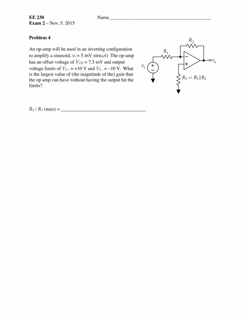
An op-amp will be used in an inverting configuration to amplify a sinusoid, vi = 5 mV sin(ωt) The op-amp has an offset voltage of VOS = 7.5 mV and output voltage limits of VL+ = +10 V and VL– = –10 V. What is the largest value of (the magnitude of the) gain that the op amp can have without having the output hit the limits?
R2 / R1 (max) = ___________________________________
+–
+–
vi
R1
R2
vo
R3 = R1�R2

EE 230 Name__________________________________________Exam 2 – Nov. 5, 2015
Possibly useful information
Op amp non-ideal effects:
Bias current and offset voltage add DC voltage to the output.
Gain-bandwidth limitation: closed-loop Go·fcl = GBW of op amp
slew rate: for sinusoidal output:
Comparators:
Non-inverting:
Inverting:
Non-linear oscillators:
Non-inverting:
Inverting:
First-order filters:
low-pass:
high-pass:
vo =
�R2 � R3 � R2R3
R1
�Ibias +
�1+
R2R1
�Vos
SR =dvodt
��max ωVA < SR
VTL = VREF
�1+
RaRb
��
�RaRb
�VL+ ; VTH = VREF
�1+
RaRb
��
�RaRb
�VL�
VTL =VREF + Ra
Rb VL�
1+ RaRb
; VTH =VREF + Ra
Rb VL+
1+ RaRb
TL = RC�VTH � VTL��VL�
��
�TH = RC
�VTH � VTL
VL+
�
TL = RC ln
�VL� � VTHVL� � VTL
�TH = RC ln
�VL+ � VTLVL+ � VTH
�
Tlp (s) = Goωo
s + ωo=
Go1+ s
ωo
; Tlp (jω) =Go
1+ jωωo
;��Tlp
�� =Go�
1+�
ωωo
�2
Thp (s) = Gos
s + ωo=
Go1+ ωo
s; Thp (jω) =
Go1+ ωo
jω;��Thp
�� =Go�
1+�ωoω
�2